EP3653749B1 - Cvi/cvd matrix densification process and apparatus - Google Patents
Cvi/cvd matrix densification process and apparatusDownload PDFInfo
- Publication number
- EP3653749B1 EP3653749B1EP19208990.2AEP19208990AEP3653749B1EP 3653749 B1EP3653749 B1EP 3653749B1EP 19208990 AEP19208990 AEP 19208990AEP 3653749 B1EP3653749 B1EP 3653749B1
- Authority
- EP
- European Patent Office
- Prior art keywords
- inlet
- gas
- cvi
- reactor
- chamber
- Prior art date
- Legal status (The legal status is an assumption and is not a legal conclusion. Google has not performed a legal analysis and makes no representation as to the accuracy of the status listed.)
- Active
Links
Images


Classifications
- C—CHEMISTRY; METALLURGY
- C23—COATING METALLIC MATERIAL; COATING MATERIAL WITH METALLIC MATERIAL; CHEMICAL SURFACE TREATMENT; DIFFUSION TREATMENT OF METALLIC MATERIAL; COATING BY VACUUM EVAPORATION, BY SPUTTERING, BY ION IMPLANTATION OR BY CHEMICAL VAPOUR DEPOSITION, IN GENERAL; INHIBITING CORROSION OF METALLIC MATERIAL OR INCRUSTATION IN GENERAL
- C23C—COATING METALLIC MATERIAL; COATING MATERIAL WITH METALLIC MATERIAL; SURFACE TREATMENT OF METALLIC MATERIAL BY DIFFUSION INTO THE SURFACE, BY CHEMICAL CONVERSION OR SUBSTITUTION; COATING BY VACUUM EVAPORATION, BY SPUTTERING, BY ION IMPLANTATION OR BY CHEMICAL VAPOUR DEPOSITION, IN GENERAL
- C23C16/00—Chemical coating by decomposition of gaseous compounds, without leaving reaction products of surface material in the coating, i.e. chemical vapour deposition [CVD] processes
- C23C16/44—Chemical coating by decomposition of gaseous compounds, without leaving reaction products of surface material in the coating, i.e. chemical vapour deposition [CVD] processes characterised by the method of coating
- C23C16/455—Chemical coating by decomposition of gaseous compounds, without leaving reaction products of surface material in the coating, i.e. chemical vapour deposition [CVD] processes characterised by the method of coating characterised by the method used for introducing gases into reaction chamber or for modifying gas flows in reaction chamber
- C23C16/45512—Premixing before introduction in the reaction chamber
- C—CHEMISTRY; METALLURGY
- C23—COATING METALLIC MATERIAL; COATING MATERIAL WITH METALLIC MATERIAL; CHEMICAL SURFACE TREATMENT; DIFFUSION TREATMENT OF METALLIC MATERIAL; COATING BY VACUUM EVAPORATION, BY SPUTTERING, BY ION IMPLANTATION OR BY CHEMICAL VAPOUR DEPOSITION, IN GENERAL; INHIBITING CORROSION OF METALLIC MATERIAL OR INCRUSTATION IN GENERAL
- C23C—COATING METALLIC MATERIAL; COATING MATERIAL WITH METALLIC MATERIAL; SURFACE TREATMENT OF METALLIC MATERIAL BY DIFFUSION INTO THE SURFACE, BY CHEMICAL CONVERSION OR SUBSTITUTION; COATING BY VACUUM EVAPORATION, BY SPUTTERING, BY ION IMPLANTATION OR BY CHEMICAL VAPOUR DEPOSITION, IN GENERAL
- C23C16/00—Chemical coating by decomposition of gaseous compounds, without leaving reaction products of surface material in the coating, i.e. chemical vapour deposition [CVD] processes
- C23C16/04—Coating on selected surface areas, e.g. using masks
- C23C16/045—Coating cavities or hollow spaces, e.g. interior of tubes; Infiltration of porous substrates
- C—CHEMISTRY; METALLURGY
- C23—COATING METALLIC MATERIAL; COATING MATERIAL WITH METALLIC MATERIAL; CHEMICAL SURFACE TREATMENT; DIFFUSION TREATMENT OF METALLIC MATERIAL; COATING BY VACUUM EVAPORATION, BY SPUTTERING, BY ION IMPLANTATION OR BY CHEMICAL VAPOUR DEPOSITION, IN GENERAL; INHIBITING CORROSION OF METALLIC MATERIAL OR INCRUSTATION IN GENERAL
- C23C—COATING METALLIC MATERIAL; COATING MATERIAL WITH METALLIC MATERIAL; SURFACE TREATMENT OF METALLIC MATERIAL BY DIFFUSION INTO THE SURFACE, BY CHEMICAL CONVERSION OR SUBSTITUTION; COATING BY VACUUM EVAPORATION, BY SPUTTERING, BY ION IMPLANTATION OR BY CHEMICAL VAPOUR DEPOSITION, IN GENERAL
- C23C16/00—Chemical coating by decomposition of gaseous compounds, without leaving reaction products of surface material in the coating, i.e. chemical vapour deposition [CVD] processes
- C23C16/44—Chemical coating by decomposition of gaseous compounds, without leaving reaction products of surface material in the coating, i.e. chemical vapour deposition [CVD] processes characterised by the method of coating
- C23C16/4412—Details relating to the exhausts, e.g. pumps, filters, scrubbers, particle traps
- C—CHEMISTRY; METALLURGY
- C23—COATING METALLIC MATERIAL; COATING MATERIAL WITH METALLIC MATERIAL; CHEMICAL SURFACE TREATMENT; DIFFUSION TREATMENT OF METALLIC MATERIAL; COATING BY VACUUM EVAPORATION, BY SPUTTERING, BY ION IMPLANTATION OR BY CHEMICAL VAPOUR DEPOSITION, IN GENERAL; INHIBITING CORROSION OF METALLIC MATERIAL OR INCRUSTATION IN GENERAL
- C23C—COATING METALLIC MATERIAL; COATING MATERIAL WITH METALLIC MATERIAL; SURFACE TREATMENT OF METALLIC MATERIAL BY DIFFUSION INTO THE SURFACE, BY CHEMICAL CONVERSION OR SUBSTITUTION; COATING BY VACUUM EVAPORATION, BY SPUTTERING, BY ION IMPLANTATION OR BY CHEMICAL VAPOUR DEPOSITION, IN GENERAL
- C23C16/00—Chemical coating by decomposition of gaseous compounds, without leaving reaction products of surface material in the coating, i.e. chemical vapour deposition [CVD] processes
- C23C16/44—Chemical coating by decomposition of gaseous compounds, without leaving reaction products of surface material in the coating, i.e. chemical vapour deposition [CVD] processes characterised by the method of coating
- C23C16/455—Chemical coating by decomposition of gaseous compounds, without leaving reaction products of surface material in the coating, i.e. chemical vapour deposition [CVD] processes characterised by the method of coating characterised by the method used for introducing gases into reaction chamber or for modifying gas flows in reaction chamber
- C23C16/45523—Pulsed gas flow or change of composition over time
- C—CHEMISTRY; METALLURGY
- C23—COATING METALLIC MATERIAL; COATING MATERIAL WITH METALLIC MATERIAL; CHEMICAL SURFACE TREATMENT; DIFFUSION TREATMENT OF METALLIC MATERIAL; COATING BY VACUUM EVAPORATION, BY SPUTTERING, BY ION IMPLANTATION OR BY CHEMICAL VAPOUR DEPOSITION, IN GENERAL; INHIBITING CORROSION OF METALLIC MATERIAL OR INCRUSTATION IN GENERAL
- C23C—COATING METALLIC MATERIAL; COATING MATERIAL WITH METALLIC MATERIAL; SURFACE TREATMENT OF METALLIC MATERIAL BY DIFFUSION INTO THE SURFACE, BY CHEMICAL CONVERSION OR SUBSTITUTION; COATING BY VACUUM EVAPORATION, BY SPUTTERING, BY ION IMPLANTATION OR BY CHEMICAL VAPOUR DEPOSITION, IN GENERAL
- C23C16/00—Chemical coating by decomposition of gaseous compounds, without leaving reaction products of surface material in the coating, i.e. chemical vapour deposition [CVD] processes
- C23C16/44—Chemical coating by decomposition of gaseous compounds, without leaving reaction products of surface material in the coating, i.e. chemical vapour deposition [CVD] processes characterised by the method of coating
- C23C16/455—Chemical coating by decomposition of gaseous compounds, without leaving reaction products of surface material in the coating, i.e. chemical vapour deposition [CVD] processes characterised by the method of coating characterised by the method used for introducing gases into reaction chamber or for modifying gas flows in reaction chamber
- C23C16/45561—Gas plumbing upstream of the reaction chamber
- C—CHEMISTRY; METALLURGY
- C23—COATING METALLIC MATERIAL; COATING MATERIAL WITH METALLIC MATERIAL; CHEMICAL SURFACE TREATMENT; DIFFUSION TREATMENT OF METALLIC MATERIAL; COATING BY VACUUM EVAPORATION, BY SPUTTERING, BY ION IMPLANTATION OR BY CHEMICAL VAPOUR DEPOSITION, IN GENERAL; INHIBITING CORROSION OF METALLIC MATERIAL OR INCRUSTATION IN GENERAL
- C23C—COATING METALLIC MATERIAL; COATING MATERIAL WITH METALLIC MATERIAL; SURFACE TREATMENT OF METALLIC MATERIAL BY DIFFUSION INTO THE SURFACE, BY CHEMICAL CONVERSION OR SUBSTITUTION; COATING BY VACUUM EVAPORATION, BY SPUTTERING, BY ION IMPLANTATION OR BY CHEMICAL VAPOUR DEPOSITION, IN GENERAL
- C23C16/00—Chemical coating by decomposition of gaseous compounds, without leaving reaction products of surface material in the coating, i.e. chemical vapour deposition [CVD] processes
- C23C16/44—Chemical coating by decomposition of gaseous compounds, without leaving reaction products of surface material in the coating, i.e. chemical vapour deposition [CVD] processes characterised by the method of coating
- C23C16/52—Controlling or regulating the coating process
Definitions
- the present disclosureis generally related to chemical vapor infiltration and deposition (CVI/CVD) and more specifically related to a CVI/CVD reactor and process capable of promoting uniform deposition and densification.
- CVI/CVDchemical vapor infiltration and deposition
- CVI/CVDis a known process for making composite structures including ceramic matrix composites.
- a reactant gas or gas mixturepasses around a stack of heated porous structures (e.g., fibrous preforms) in an isobaric reactor chamber.
- Current CVI/CVD reactorsprovide the reactant gas through an inlet at one end of the reactor chamber and remove gas through an outlet at an opposite end of the reactor chamber.
- the reactant gasdiffuses into one or more porous structures positioned in the reactor chamber and undergoes a reaction to form a matrix material.
- the precursor gasesare consumed by porous structures or portions of a porous structure positioned nearest the gas inlet, making less reactant gas available for porous structures or portions of a porous structure nearest the outlet of the reactor.
- a CVI/CVD reactor and processis needed that can promote uniformity in matrix densification while reducing or eliminating inefficiencies in manufacturing resulting from the need to rearrange porous structures to account for non-uniform gas distribution in the reactor.
- CVI/CVDchemical vapor infiltration and deposition
- CVI/CVDchemical vapor infiltration and deposition
- CVI/CVDChemical vapor infiltration and deposition
- CMCceramic matrix composite
- reactant gasis provided to a reactor chamber through an inlet at one end of the reactor chamber and is exhausted through an outlet at an opposite end of the reactor chamber.
- the reactant gasdiffuses into one or more porous structures positioned in the reactor chamber and undergoes a reaction to form a ceramic matrix.
- the precursor gasesare consumed by porous structures or portions of a porous structure positioned nearest the inlet, making less reactant gas available for porous structures or portions of a porous structure nearest the outlet of the reactor.
- reactant gasis alternatively fed to inlets at opposite ends of the reactor to reverse gas flow within the reactor, such that porous structures located farthest from the gas inlet in one mode of operation are located closest to the gas inlet in another mode of operation. Alternating gas feed in this manner promotes uniform infiltration and matrix densification by increasing the availability of reactant gas throughout the reactor.
- FIG. 1is a schematic view of CVI/CVD assembly 10, illustrating the direction of gas flow through the reactor in a first mode of operation.
- FIG. 2is a schematic view of CVI/CVD assembly 10, illustrating the direction of gas flow through the reactor in a second mode of operation.
- CVI/CVD assembly 10includes reactor 12, having gas inlets 14, 16, gas outlets 18, 20, reaction chamber 22, and completion beds 24, 26. Chamber 22 can be subdivided into a plurality of levels or sub-chambers 28-32, defined between gas distributor plates 34-39.
- CVI/CVD assembly 10further includes heat source 46, reactant gas source 48, purge gas source 50, a plurality of gas lines 52, 54, 56, 58, 60, 62 fluidly connected to reactor 12 and operable via valves 64, 66, 68, 70, 72, 74, 75, and vacuum pump 76 fluidly connected to reactor 12.
- CVI/CVD assembly 10can include controller 78, which can be communicatively coupled to heat source 46, valves 64-75, vacuum pump 76, and other components of CVI/CVD assembly 10 to facilitate operation of CVI/CVD assembly 10.
- CVI/CVD reactor 12can be an isobaric reactor configured to house one or more substrates 80 and to facilitate chemical vapor infiltration of a reactant gas into substrates 80 and/or deposition of a reactant gas onto substrates 80.
- Substrate 80can be a porous structure, such as a fibrous preform made of carbon (C) or silicon carbide (SiC) fibers.
- CVIcan be used for the manufacture of CMC components in which a fibrous preform is densified with a refractory matrix.
- CMCsexamples include C/C composites, C/SiC composites, SiC/SiC composites, alumina (Al 2 O 3 )/Al 2 O 3 composites, and the like, where the first compound makes up the fibrous preform and the second compound forms the matrix.
- CVIcan be used to apply interphase coatings (e.g., boron nitride) to fibers prior to matrix densification.
- CVDmay be used to deposit a coating on a non-porous structure or preform.
- CVI/CVD assembly 10 and the disclosed methodcan replace conventional isobaric CVI/CVD assemblies and methods of manufacture where uniform infiltration and deposition is an issue, and that the disclosed CVI/CVD assembly 10 and method is not limited to the manufacture of CMCs.
- substrates 80can be stacked inside CVI/CVD reaction chamber 22, separated by spacers 82.
- Spacers 82can be porous structures capable of separating adjacent substrates 80 within a stack, while allowing gas to flow between adjacent substrates 80, into substrates 80, and onto external surfaces of substrates 80.
- Chamber 22can be divided into multiple levels or sub-chambers 28-32, defined between distributor plates 34-39.
- a plurality of substrates 80can be divided among three levels 29, 30, and 31, defined between distributor plates 35, 36, and 37.
- Distributor plates 35, 36, and 37can be used to provide support (e.g., shelves) for multiple substrates 80 within chamber 22 and to facilitate reactant gas redistribution among levels 29, 30, and 31.
- Gas distributor plates 34-39can be perforated or otherwise porous members that allow for diffusion or flow of reactant gas between chambers 28-32.
- Gas distributor plates 34-39can be oriented parallel to top and bottom walls of reactor 12 to divide reactor 12 into levels or sub-chambers oriented in a stacked arrangement from the top to the bottom of reactor 12 or between gas inlet 14 and gas outlet 18. While FIGS.
- FIG. 1 and 2illustrate substrates 80 being divided among three levels or sub-chambers 29, 30, and 31, it will be understood by one of ordinary skill in the art that the number of levels as well as the height of each level can be increased or decreased depending on the application.
- Distributor plates 35-38can rest on adjustable supports on an inner wall of chamber 22 or be secured in a manner that allows for the removal, addition, or relocation of distributor plates as needed.
- the effectiveness of CVI/CVD assembly 10 and disclosed methodcan be limited primarily by the consumption of reactant gas by substrates 80 located closest to the gas inlet 14, 16 in use, and thereby availability of reactant gas for substrates 80 separated from the gas inlet 14, 16 in use by other substrates 80.
- Isobaric CVIis a relatively slow process, but can be used to densify a large number of preforms 80 at a time.
- the disclosed CVI/CVD assembly 10 and methodcan be used to uniformly densify a large number of fibrous preforms 80 at a time while reducing or eliminating the need to rearrange fibrous preforms 80 within reactor 12. While particularly suited to the process of densifying multiple fibrous preforms 80 simultaneously, it will be understood by one of ordinary skill in the art that the disclosed CVI/CVD assembly 10 and method can also be used to densify a small number of fibrous preforms 80 or a single fibrous preform 80.
- Reactant gascan enter CVI/CVD reactor 12 through one of gas inlets 14 and 16.
- the reactant gascan be a gaseous ceramic precursor, for example, methyl trichlorosilane (MTS) and hydrogen (H 2 ), which diffuses into porous preforms 80 and reacts to form SiC.
- MTSmethyl trichlorosilane
- H 2hydrogen
- the SiCis deposited inside the pores of preforms 80 thereby densifying preforms 80.
- Reactant gascan flow from gas inlet 14 toward gas outlet 18 or from gas inlet 16 toward gas outlet 20, depending on the mode of operation.
- Reactant gascan surround preforms 80 and diffuse into preform pores.
- Heat source 46can apply radiative or thermal energy to heat reactor chambers of reactor 12 to induce a chemical reaction.
- Heat source 46can be any heat source and can be provided to reactor 12 in any configuration known in the art.
- reactant gasmay be heated by a preheater prior to entering reactor 12 as known in the art.
- reactor 12can be an isothermal reactor, such that reaction chamber 22 is kept at a uniform temperature.
- reactor 12can have a thermal gradient.
- a temperature gradientcan enhance gas diffusivity and the rate of chemical reaction can increase with increasing temperature.
- the temperaturecan be greatest in the level 31, 29 located farthest from the open inlet 14, 16 to push the reaction where less reactant gas is available.
- the thermal gradientcan be reversed in conjunction with the reversal of the flow of reactant gas to facilitate uniform densification of preforms 80.
- reactant gascan enter CVI/CVD reactor 12 through inlet 14 and flow toward gas outlet 18.
- the direction of gas flowcan be reversed in a second mode of operation, such that reactant gas enters CVI/CVD reactor 12 through gas inlet 16 (located opposite of gas inlet 14 in reactor 12) and flows toward gas outlet 20 (located opposite of gas outlet 18 in reactor 12).
- gas inlet 14can be located at the top of reactor 12 with gas outlet located on the bottom of reactor 12
- gas inlet 16can be located at the bottom of reactor 12 with gas outlet 20 located on the top of reactor 12.
- gas inlets 12 and 14 and gas outlets 16 and 18can be located on opposite walls of reactor 12 or can be otherwise disposed to direct gas flow through reactor 12 in opposite directions. As shown in FIGS. 1 and 2 , gas inlets 14, 16 and gas outlets 18, 20 can be generally centrally located on top and bottom ends of reactor 12. In some embodiments, gas inlet 14 can be provided by a fluid conduit 54 that extends through a chamber of gas outlet 20 and into gas mixing chamber 28 of reactor 12. Likewise, gas inlet 16 can be provided by a fluid conduit 56 that extends through a chamber of gas outlet 18 and into gas mixing chamber 32 of reactor 12. Mixing chambers 28 and 32, defined between distributor plates 34 and 35 and 38 and 39, respectively, allow reactant gases to heat up and mix before reaching substrates 80.
- the reactant gas flow directioncan be reversed multiple times during a CVI/CVD process to promote uniform matrix densification of preforms 80.
- the number of times gas flow is reversedcan vary by application and depend on reaction rate and preform geometry.
- gas flowcan be reversed 4 to 20 times during a CVI/CVD process lasting hundreds of hours. Modeling and simulation can be used to predict densification and determine how frequently gas flow should be reversed to promote uniform densification of preforms 80.
- Reactant gascan be supplied to gas inlets 14, 16 by one or more gas sources 48. Multiple gas sources can feed gas inlets 14, 16 to avoid mixing reactant gases prior to entry into reactor 12. As illustrated in FIGS. 1 and 2 , reactant gas can be supplied to gas inlets 14, 16 via gas line 52, equipped with valve 64 with mass flow controller 88 for regulating a flow rate of the reactant gas. Additional inlet valves 66, 68 on gas lines 54, 56 to inlets 14, 16, respectively, can be used to open and close gas inlets 14, 16.
- gas lines 52, 54, and 56can each comprise multiple conduits with multiple independent valves 64, 66, 68 for separate delivery of reactant gases as may be necessary to prevent reaction of the reactant gas prior to delivery to reactor 12.
- Gas lines 52, 54, 56can comprise pipes, conduits, or other suitable devices for delivering fluid.
- the multiple conduitscan be bundled, without mixing the gases, in a single inlet pipe 14, 16 that extends into reactor 12.
- valve 66controls the opening and closing of gas inlet 14 while valve 68 controls the opening and closing of gas inlet 16.
- valves 64, 66, and 68can be controlled manually or automatically via controller 78 according to preprogrammed parameters and schedule.
- gas inlet 14is open, allowing reactant gas to flow into reactor 12 toward gas outlet 18, which is also open (gas flow direction shown by arrows).
- Gas inlet 16 and gas outlet 20are in a closed position during the first mode of operation.
- Reactant gascan enter reactor 12 in mixing chamber 28, defined between distributor plates 34 and 35, which are oriented parallel to the top wall of reactor 12.
- Reactant gascan fill mixing chamber 28 and enter reactor chamber 22 through a plurality of perforations or openings in distributor plate 35.
- Mixing chamber 28can facilitate mixing and heating of reactant gas and uniform gas distribution across reaction chamber 22 to promote uniform densification of preforms 80.
- Vacuum pump 76can be fluidly connected to gas outlet 18 and can draw reactant gas from reactor 12 through gas outlet 18. The flow of reactant gas toward gas outlet 18 limits flow of reactant gas through distributor plate 34 and completion bed 24 located adjacent to gas inlet 14.
- reaction chamber 22is equipped with three levels or sub-chambers 29, 30, 31, with level 29 located nearest gas inlet 14, level 31 located nearest gas inlet 16, and level 30 positioned between levels 29 and 31.
- Preforms in centrally-located level 30can be densified to a lesser degree than preforms 80 in level 29, which is positioned nearest to gas inlet 14 and mixing chamber 28.
- the direction of gas flowis reversed in a second mode of operation, which increases the amount of reactant gas available in level 31 of reaction chamber 22.
- gas inlet 16is open allowing reactant gas to flow into reactor 12 from the bottom of reactor 12 toward gas outlet 20 at the top of reactor 12 (gas flow direction shown by arrows), which is opposite the direction of gas flow in the first mode of operation.
- Gas inlet 14 and gas outlet 18are in a closed position during the second mode of operation.
- reactant gascan enter reactor 12 in mixing chamber 32 defined between distributor plates 38 and 39.
- Reactant gascan fill mixing chamber 32 and enter reaction chamber 22 through a plurality of perforations or openings in distributor plate 38.
- Mixing chamber 32can facilitate mixing and heating of reactant gas and uniform gas distribution across reaction chamber 22 to promote uniform densification of preforms 80.
- Vacuum pump 76can be fluidly connected to gas outlet 20 and can draw reactant gas from reactor 12 through gas outlet 20.
- the flow of reactant gas toward gas outlet 20can limit the flow of reactant gas through distributor plate 39 and completion bed 26 located adjacent to gas inlet 16.
- preforms located in levels 30 and 31are densified to a greater extent than preforms located in level 29 in the second mode of operation.
- preforms in centrally-located level 30can be densified to a lesser extent than the preforms in the levels closest to the gas inlet in use, but can be densified to a greater extent than the preforms located farthest from the gas inlet in use, such that densification of all preforms 80 within all levels 29, 30, 31 can be substantially uniform.
- Vacuum pump 76can be used to draw reactant gas flow from gas inlet 14, 16 toward the respective gas outlet 18, 20 in both the first and second modes of operation.
- a vacuumcan be applied to reactor 12 in a manner that maintains isobaric conditions or constant pressure within reactor 12.
- Vacuum pump 76can be fluidly connected to outlet 18 via gas line 60 and can be fluidly connected to gas outlet 20 via gas line 58.
- Gas lines 58, 60can comprise pipes, conduits, or other suitable devices for delivering fluid.
- Valves 70 and 72can be used to open and close gas outlets 18 and 20, respectively. In alternative embodiments, a single valve can be used to open and close both gas outlets 18 and 20.
- Pressure transducer 83can measure a pressure in outlet gas lines 58, 60.
- Valve 74 located on gas line 60can be used to adjust the vacuum to control the pressure inside reactor 12.
- valves 70, 72, 74can be manually or automatically controlled via controller 78 according to preprogrammed parameters and schedule.
- completion beds 24, 26, respectivelyare positioned adjacent to gas outlets 18, 20 and can extend fully across reactor 12 to separate mixing chambers 28, 32 from gas outlets 18, 20, respectively, such that any gas exiting reactor 12 must pass through one of completion beds 24, 26.
- Completion beds 24, 26can be defined between a reactor wall and distributor plate 34, 39. Distributor plates 34, 39 allow gases to diffuse or flow into completion beds 24, 26 and into gas outlets 18, 20.
- completion bed 24is defined between distributor plate 34 and a top wall of reactor 12, which opens to gas outlet 20.
- Completion bed 26is defined between distributor plate 39 and a bottom wall of reactor 12, which opens to gas outlet 18.
- An inert gascan be delivered to reactor 12 prior to a CVI/CVD process to remove atmospheric air from reactor 12 and after a CVI/CVD process to remove reactant gas remaining in reactor 12.
- Inert gascan be delivered to reactor 12 from purge gas source 50 via gas line 62 and gas inlet 12 or 14.
- Valve 75 with mass flow controller 90can be used to control the flow of purge gas into reactor 12.
- Vacuum pump 76can be used to draw purge gas though reactor 12 and out through one of outlets 18, 20.
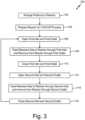
- FIG. 3illustrates method 100 of performing CVI/CVD.
- Preforms or substrates 80can be arranged in reactor 12 and reactor 12 can be sealed closed (step 102).
- preforms 80can be arranged in stacks separated by spacers 82 and can be arranged in one or more reaction chamber levels 29, 20, 31.
- CVI/CVD assembly 10can be further prepared for operation in step 104 (e.g., an inert gas can be delivered to reactor 12 to purge reactor 12 of ambient air, and reactor 12 can be heated and vacuumed to CVI process conditions).
- inlet gas valve 66 and outlet gas valve 72can be opened to allow flow of reactant gas through reactor 12 (step 106).
- Reactant gascan be fed to reactor 12 from reactant gas source 48 via gas line 54 and gas inlet 14, and vacuum pump 76 can be used to draw gas from reactor 12 through completion bed 26 to complete reaction of any unreacted gas, and to draw exhaust gas from completion bed 26 out of reactor 12 via gas outlet 18 (step 108).
- gas inlet 14 and gas outlet 18can be closed via valves 66 and 72, respectively (step 110) and gas inlet 16 and gas outlet 20 can be opened via valves 68 and 70, respectively (step 112). This reverses gas flow within reactor 12, causing reactant gas to flow from gas inlet 16 toward gas outlet 20 in a second mode of operation (step 114).
- vacuum pump 76can be used to draw gas from reactor 12 through completion bed 24 to complete reaction of any unreacted gas, and to draw exhaust gas from completion bed 24 out of reactor 12 through gas outlet 20.
- gas inlet 16 and gas outlet 20can be closed (step 116) and steps 106 through 108 can be repeated to again reverse the direction of flow of reactant gas through reactor 12.
- Steps 106 through 116can be repeated multiple times throughout the CVI/CVD process to promote uniform densification of preforms 80.
- inert gascan be fed to reactor 12 via gas inlet 14 or 16 to purge reactor 12 of unreacted precursor gas.
- CVI/CVD assembly 10 and the disclosed methodprovide an efficient means for providing uniform matrix densification of fibrous preforms.
- CVI/CVD assembly 10can improve uniformity in matrix densification while eliminating the need to shut down the CVI/CVD process to rearrange fibrous preforms within reactor 12. This can reduce operation time and production costs.
- any relative terms or terms of degree used hereinsuch as “substantially”, “essentially”, “generally”, “approximately” and the like, should be interpreted in accordance with and subject to any applicable definitions or limits expressly stated herein.
- any relative terms or terms of degree used hereinshould be interpreted to broadly encompass any relevant disclosed embodiments as well as such ranges or variations as would be understood by a person of ordinary skill in the art in view of the entirety of the present disclosure, such as to encompass ordinary manufacturing tolerance variations, incidental alignment variations, transient alignment or shape variations induced by thermal, rotational or vibrational operational conditions, and the like.
- any relative terms or terms of degree used hereinshould be interpreted to encompass a range that expressly includes the designated quality, characteristic, parameter or value, without variation, as if no qualifying relative term or term of degree were utilized in the given disclosure or recitation.
Landscapes
- Chemical & Material Sciences (AREA)
- General Chemical & Material Sciences (AREA)
- Chemical Kinetics & Catalysis (AREA)
- Engineering & Computer Science (AREA)
- Materials Engineering (AREA)
- Mechanical Engineering (AREA)
- Metallurgy (AREA)
- Organic Chemistry (AREA)
- Chemical Vapour Deposition (AREA)
Description
- The present disclosure is generally related to chemical vapor infiltration and deposition (CVI/CVD) and more specifically related to a CVI/CVD reactor and process capable of promoting uniform deposition and densification.
- CVI/CVD is a known process for making composite structures including ceramic matrix composites. In conventional CVI/CVD processes, a reactant gas or gas mixture passes around a stack of heated porous structures (e.g., fibrous preforms) in an isobaric reactor chamber. Current CVI/CVD reactors provide the reactant gas through an inlet at one end of the reactor chamber and remove gas through an outlet at an opposite end of the reactor chamber. The reactant gas diffuses into one or more porous structures positioned in the reactor chamber and undergoes a reaction to form a matrix material. The precursor gases are consumed by porous structures or portions of a porous structure positioned nearest the gas inlet, making less reactant gas available for porous structures or portions of a porous structure nearest the outlet of the reactor. This can lead to non-uniform matrix densification within a single porous structure or between multiple porous structures based on their location within the reactor chamber. To promote uniform infiltration and matrix densification, the CVI/CVD reactor is shut down and the porous structures are rearranged within the reactor chamber. Such rearrangement may be required multiple times during the CVI/CVD process to improve density uniformity.
US2009/061643A1 ,FR1524507A EP3211120A1 andUS2006/196419A1 disclose processes of the prior art. - A CVI/CVD reactor and process is needed that can promote uniformity in matrix densification while reducing or eliminating inefficiencies in manufacturing resulting from the need to rearrange porous structures to account for non-uniform gas distribution in the reactor.
- From one aspect, there is provided a chemical vapor infiltration and deposition (CVI/CVD) reactor according to claim 1.
- From another aspect, there is provided a chemical vapor infiltration and deposition (CVI/CVD) process according to claim 9.
- The present summary is provided only by way of example, and not limitation. Other aspects and embodiments of the present disclosure will be appreciated in view of the entirety of the present disclosure, including the entire text, claims, and accompanying figures.
FIG. 1 is a schematic view of a chemical vapor deposition/chemical vapor infiltration (CVI/CVD) reactor illustrating the direction of gas flow through the reactor in a first mode of operation.FIG. 2 is a schematic view of the CVI/CVD reactor ofFIG. 1 illustrating the direction of gas flow through the reactor in a second mode of operation.FIG. 3 illustrates a process of performing CVI/CVD.- While the above-identified figures set forth one or more embodiments of the present disclosure, other embodiments are also contemplated, as noted in the discussion. In all cases, this disclosure presents the invention by way of representation and not limitation. It should be understood that numerous other modifications and embodiments can be devised by those skilled in the art, which fall within the scope and spirit of the principles of the invention. The figures may not be drawn to scale, and applications and embodiments of the present invention may include features and components not specifically shown in the drawings.
- Chemical vapor infiltration and deposition (CVI/CVD) can be used to produce ceramic matrix composite (CMC) components suited for high temperature applications including use in gas turbine engines. In conventional isobaric CVI/CVD reactors, reactant gas is provided to a reactor chamber through an inlet at one end of the reactor chamber and is exhausted through an outlet at an opposite end of the reactor chamber. The reactant gas diffuses into one or more porous structures positioned in the reactor chamber and undergoes a reaction to form a ceramic matrix. The precursor gases are consumed by porous structures or portions of a porous structure positioned nearest the inlet, making less reactant gas available for porous structures or portions of a porous structure nearest the outlet of the reactor. This can lead to non-uniform matrix densification within a single porous structure or between multiple porous structures based on their location within the reactor chamber. In the CVI/CVD process and apparatus of the present disclosure, reactant gas is alternatively fed to inlets at opposite ends of the reactor to reverse gas flow within the reactor, such that porous structures located farthest from the gas inlet in one mode of operation are located closest to the gas inlet in another mode of operation. Alternating gas feed in this manner promotes uniform infiltration and matrix densification by increasing the availability of reactant gas throughout the reactor.
FIG. 1 is a schematic view of CVI/CVD assembly 10, illustrating the direction of gas flow through the reactor in a first mode of operation.FIG. 2 is a schematic view of CVI/CVD assembly 10, illustrating the direction of gas flow through the reactor in a second mode of operation. CVI/CVD assembly 10 includesreactor 12, havinggas inlets gas outlets reaction chamber 22, andcompletion beds Chamber 22 can be subdivided into a plurality of levels or sub-chambers 28-32, defined between gas distributor plates 34-39. CVI/CVD assembly 10 further includesheat source 46,reactant gas source 48,purge gas source 50, a plurality ofgas lines reactor 12 and operable viavalves vacuum pump 76 fluidly connected toreactor 12. In some embodiments, CVI/CVD assembly 10 can includecontroller 78, which can be communicatively coupled toheat source 46, valves 64-75,vacuum pump 76, and other components of CVI/CVD assembly 10 to facilitate operation of CVI/CVD assembly 10.- CVI/
CVD reactor 12 can be an isobaric reactor configured to house one ormore substrates 80 and to facilitate chemical vapor infiltration of a reactant gas intosubstrates 80 and/or deposition of a reactant gas ontosubstrates 80.Substrate 80 can be a porous structure, such as a fibrous preform made of carbon (C) or silicon carbide (SiC) fibers. CVI can be used for the manufacture of CMC components in which a fibrous preform is densified with a refractory matrix. Examples of CMCs include C/C composites, C/SiC composites, SiC/SiC composites, alumina (Al2O3)/Al2O3 composites, and the like, where the first compound makes up the fibrous preform and the second compound forms the matrix. In some embodiments, CVI can be used to apply interphase coatings (e.g., boron nitride) to fibers prior to matrix densification. In some embodiments, CVD may be used to deposit a coating on a non-porous structure or preform. While the present disclosure is generally directed to the manufacture of CMC components, it will be understood by one of ordinary skill in the art that CVI/CVD assembly 10 and the disclosed method can replace conventional isobaric CVI/CVD assemblies and methods of manufacture where uniform infiltration and deposition is an issue, and that the disclosed CVI/CVD assembly 10 and method is not limited to the manufacture of CMCs. - As illustrated in
FIGS. 1 and2 ,substrates 80 can be stacked inside CVI/CVD reaction chamber 22, separated byspacers 82.Spacers 82 can be porous structures capable of separatingadjacent substrates 80 within a stack, while allowing gas to flow betweenadjacent substrates 80, intosubstrates 80, and onto external surfaces ofsubstrates 80.Chamber 22 can be divided into multiple levels or sub-chambers 28-32, defined between distributor plates 34-39. As illustrated inFIGS. 1 and2 , a plurality ofsubstrates 80 can be divided among threelevels distributor plates Distributor plates multiple substrates 80 withinchamber 22 and to facilitate reactant gas redistribution amonglevels reactor 12 to dividereactor 12 into levels or sub-chambers oriented in a stacked arrangement from the top to the bottom ofreactor 12 or betweengas inlet 14 andgas outlet 18. WhileFIGS. 1 and2 illustrate substrates 80 being divided among three levels orsub-chambers chamber 22 or be secured in a manner that allows for the removal, addition, or relocation of distributor plates as needed. As will become evident, the effectiveness of CVI/CVD assembly 10 and disclosed method can be limited primarily by the consumption of reactant gas bysubstrates 80 located closest to thegas inlet substrates 80 separated from thegas inlet other substrates 80. Isobaric CVI is a relatively slow process, but can be used to densify a large number ofpreforms 80 at a time. The disclosed CVI/CVD assembly 10 and method can be used to uniformly densify a large number offibrous preforms 80 at a time while reducing or eliminating the need to rearrangefibrous preforms 80 withinreactor 12. While particularly suited to the process of densifyingmultiple fibrous preforms 80 simultaneously, it will be understood by one of ordinary skill in the art that the disclosed CVI/CVD assembly 10 and method can also be used to densify a small number offibrous preforms 80 or a singlefibrous preform 80. - Reactant gas can enter CVI/
CVD reactor 12 through one ofgas inlets porous preforms 80 and reacts to form SiC. The SiC is deposited inside the pores ofpreforms 80 thereby densifyingpreforms 80. Reactant gas can flow fromgas inlet 14 towardgas outlet 18 or fromgas inlet 16 towardgas outlet 20, depending on the mode of operation. Reactant gas can surroundpreforms 80 and diffuse into preform pores. Factors effecting deposition of precursor gas infibrous preforms 80 can include concentration, flow direction, flow rate, and residence time of reactant gas inreactor 12; temperature, pressure, geometry, and location offibrous preforms 80; geometry ofreactor 12; and the like. Heatsource 46 can apply radiative or thermal energy to heat reactor chambers ofreactor 12 to induce a chemical reaction. Heatsource 46 can be any heat source and can be provided toreactor 12 in any configuration known in the art. In some embodiments, reactant gas may be heated by a preheater prior to enteringreactor 12 as known in the art. In some embodiments,reactor 12 can be an isothermal reactor, such thatreaction chamber 22 is kept at a uniform temperature. In alternative embodiments,reactor 12 can have a thermal gradient. A temperature gradient can enhance gas diffusivity and the rate of chemical reaction can increase with increasing temperature. The temperature can be greatest in thelevel open inlet preforms 80. - During a first mode of operation, reactant gas can enter CVI/
CVD reactor 12 throughinlet 14 and flow towardgas outlet 18. To promote uniform densification or coating ofpreforms 80, the direction of gas flow can be reversed in a second mode of operation, such that reactant gas enters CVI/CVD reactor 12 through gas inlet 16 (located opposite ofgas inlet 14 in reactor 12) and flows toward gas outlet 20 (located opposite ofgas outlet 18 in reactor 12). In some embodiments,gas inlet 14 can be located at the top ofreactor 12 with gas outlet located on the bottom ofreactor 12, andgas inlet 16 can be located at the bottom ofreactor 12 withgas outlet 20 located on the top ofreactor 12. In other embodiments,gas inlets gas outlets reactor 12 or can be otherwise disposed to direct gas flow throughreactor 12 in opposite directions. As shown inFIGS. 1 and2 ,gas inlets gas outlets reactor 12. In some embodiments,gas inlet 14 can be provided by afluid conduit 54 that extends through a chamber ofgas outlet 20 and intogas mixing chamber 28 ofreactor 12. Likewise,gas inlet 16 can be provided by afluid conduit 56 that extends through a chamber ofgas outlet 18 and intogas mixing chamber 32 ofreactor 12. Mixingchambers distributor plates substrates 80. The reactant gas flow direction can be reversed multiple times during a CVI/CVD process to promote uniform matrix densification ofpreforms 80. The number of times gas flow is reversed can vary by application and depend on reaction rate and preform geometry. In a non-limiting embodiment, gas flow can be reversed 4 to 20 times during a CVI/CVD process lasting hundreds of hours. Modeling and simulation can be used to predict densification and determine how frequently gas flow should be reversed to promote uniform densification ofpreforms 80. - Reactant gas can be supplied to
gas inlets more gas sources 48. Multiple gas sources can feedgas inlets reactor 12. As illustrated inFIGS. 1 and2 , reactant gas can be supplied togas inlets gas line 52, equipped withvalve 64 withmass flow controller 88 for regulating a flow rate of the reactant gas.Additional inlet valves gas lines inlets close gas inlets gas lines independent valves reactor 12.Gas lines single inlet pipe reactor 12. As illustrated inFIGS. 1 and2 ,valve 66 controls the opening and closing ofgas inlet 14 whilevalve 68 controls the opening and closing ofgas inlet 16. In alternative embodiments, a single valve may be used to control gas flow fromgas line 52 togas inlets gas inlet gas inlets valves controller 78 according to preprogrammed parameters and schedule. - In the first mode of operation (illustrated in
FIG. 1 ),gas inlet 14 is open, allowing reactant gas to flow intoreactor 12 towardgas outlet 18, which is also open (gas flow direction shown by arrows).Gas inlet 16 andgas outlet 20 are in a closed position during the first mode of operation. Reactant gas can enterreactor 12 in mixingchamber 28, defined betweendistributor plates reactor 12. Reactant gas can fill mixingchamber 28 and enterreactor chamber 22 through a plurality of perforations or openings indistributor plate 35. Mixingchamber 28 can facilitate mixing and heating of reactant gas and uniform gas distribution acrossreaction chamber 22 to promote uniform densification ofpreforms 80.Vacuum pump 76 can be fluidly connected togas outlet 18 and can draw reactant gas fromreactor 12 throughgas outlet 18. The flow of reactant gas towardgas outlet 18 limits flow of reactant gas throughdistributor plate 34 andcompletion bed 24 located adjacent togas inlet 14. As illustrated inFIGS. 1 and2 ,reaction chamber 22 is equipped with three levels or sub-chambers 29, 30, 31, withlevel 29 located nearestgas inlet 14,level 31 located nearestgas inlet 16, andlevel 30 positioned betweenlevels reactor 12 fromgas inlet 14, it is consumed by preforms 80 with more reactant gas being consumed by the preforms located inlevels gas inlet 14, and with less reactant gas available for densifying the preforms inlevel 31 positioned farthest fromgas inlet 14. Preforms in centrally-locatedlevel 30 can be densified to a lesser degree than preforms 80 inlevel 29, which is positioned nearest togas inlet 14 and mixingchamber 28. To promote uniform densification, the direction of gas flow is reversed in a second mode of operation, which increases the amount of reactant gas available inlevel 31 ofreaction chamber 22. - As illustrated in
FIG. 2 , during the second mode of operation,gas inlet 16 is open allowing reactant gas to flow intoreactor 12 from the bottom ofreactor 12 towardgas outlet 20 at the top of reactor 12 (gas flow direction shown by arrows), which is opposite the direction of gas flow in the first mode of operation.Gas inlet 14 andgas outlet 18 are in a closed position during the second mode of operation. In the second mode of operation, reactant gas can enterreactor 12 in mixingchamber 32 defined betweendistributor plates chamber 32 and enterreaction chamber 22 through a plurality of perforations or openings indistributor plate 38. Mixingchamber 32 can facilitate mixing and heating of reactant gas and uniform gas distribution acrossreaction chamber 22 to promote uniform densification ofpreforms 80.Vacuum pump 76 can be fluidly connected togas outlet 20 and can draw reactant gas fromreactor 12 throughgas outlet 20. The flow of reactant gas towardgas outlet 20 can limit the flow of reactant gas throughdistributor plate 39 andcompletion bed 26 located adjacent togas inlet 16. As reactant gas flows throughreactor 12 frominlet 16 towardoutlet 20, it is consumed by preforms 80 with more reactant gas being consumed by the preforms located inlevels gas inlet 16, and with less reactant gas available for densifying the preforms inlevel 29 positioned farthest fromgas inlet 16. As such, preforms located inlevels level 29 in the second mode of operation. In both the first mode and the second mode of operation, preforms in centrally-locatedlevel 30 can be densified to a lesser extent than the preforms in the levels closest to the gas inlet in use, but can be densified to a greater extent than the preforms located farthest from the gas inlet in use, such that densification of all preforms 80 within alllevels Vacuum pump 76 can be used to draw reactant gas flow fromgas inlet respective gas outlet reactor 12 in a manner that maintains isobaric conditions or constant pressure withinreactor 12.Vacuum pump 76 can be fluidly connected tooutlet 18 viagas line 60 and can be fluidly connected togas outlet 20 viagas line 58.Gas lines Valves close gas outlets gas outlets Pressure transducer 83 can measure a pressure inoutlet gas lines Valve 74 located ongas line 60 can be used to adjust the vacuum to control the pressure insidereactor 12. In some embodiments,valves controller 78 according to preprogrammed parameters and schedule.- Before exiting CVI/
CVD reactor 12 throughgas outlets completion beds FIGS. 1 and2 ,completion beds gas outlets reactor 12 to separate mixingchambers gas outlets gas exiting reactor 12 must pass through one ofcompletion beds Completion beds distributor plate Distributor plates completion beds gas outlets FIGS. 1 and2 ,completion bed 24 is defined betweendistributor plate 34 and a top wall ofreactor 12, which opens togas outlet 20.Completion bed 26 is defined betweendistributor plate 39 and a bottom wall ofreactor 12, which opens togas outlet 18. - An inert gas can be delivered to
reactor 12 prior to a CVI/CVD process to remove atmospheric air fromreactor 12 and after a CVI/CVD process to remove reactant gas remaining inreactor 12. Inert gas can be delivered toreactor 12 frompurge gas source 50 viagas line 62 andgas inlet Valve 75 withmass flow controller 90 can be used to control the flow of purge gas intoreactor 12.Vacuum pump 76 can be used to draw purge gas thoughreactor 12 and out through one ofoutlets FIG. 3 illustratesmethod 100 of performing CVI/CVD. Preforms orsubstrates 80 can be arranged inreactor 12 andreactor 12 can be sealed closed (step 102). As previously disclosed, preforms 80 can be arranged in stacks separated byspacers 82 and can be arranged in one or morereaction chamber levels CVD assembly 10 can be further prepared for operation in step 104 (e.g., an inert gas can be delivered toreactor 12 to purgereactor 12 of ambient air, andreactor 12 can be heated and vacuumed to CVI process conditions). In the first mode of operation,inlet gas valve 66 andoutlet gas valve 72 can be opened to allow flow of reactant gas through reactor 12 (step 106). Reactant gas can be fed toreactor 12 fromreactant gas source 48 viagas line 54 andgas inlet 14, andvacuum pump 76 can be used to draw gas fromreactor 12 throughcompletion bed 26 to complete reaction of any unreacted gas, and to draw exhaust gas fromcompletion bed 26 out ofreactor 12 via gas outlet 18 (step 108). After a period of densification,gas inlet 14 andgas outlet 18 can be closed viavalves gas inlet 16 andgas outlet 20 can be opened viavalves reactor 12, causing reactant gas to flow fromgas inlet 16 towardgas outlet 20 in a second mode of operation (step 114). In the second mode of operation,vacuum pump 76 can be used to draw gas fromreactor 12 throughcompletion bed 24 to complete reaction of any unreacted gas, and to draw exhaust gas fromcompletion bed 24 out ofreactor 12 throughgas outlet 20. After a period of densification,gas inlet 16 andgas outlet 20 can be closed (step 116) and steps 106 through 108 can be repeated to again reverse the direction of flow of reactant gas throughreactor 12.Steps 106 through 116 can be repeated multiple times throughout the CVI/CVD process to promote uniform densification ofpreforms 80. Following completion of the CVI/CVD process, inert gas can be fed toreactor 12 viagas inlet reactor 12 of unreacted precursor gas.- CVI/
CVD assembly 10 and the disclosed method provide an efficient means for providing uniform matrix densification of fibrous preforms. By alternating reactant gas flow throughreactor 12, CVI/CVD assembly 10 can improve uniformity in matrix densification while eliminating the need to shut down the CVI/CVD process to rearrange fibrous preforms withinreactor 12. This can reduce operation time and production costs. - Any relative terms or terms of degree used herein, such as "substantially", "essentially", "generally", "approximately" and the like, should be interpreted in accordance with and subject to any applicable definitions or limits expressly stated herein. In all instances, any relative terms or terms of degree used herein should be interpreted to broadly encompass any relevant disclosed embodiments as well as such ranges or variations as would be understood by a person of ordinary skill in the art in view of the entirety of the present disclosure, such as to encompass ordinary manufacturing tolerance variations, incidental alignment variations, transient alignment or shape variations induced by thermal, rotational or vibrational operational conditions, and the like. Moreover, any relative terms or terms of degree used herein should be interpreted to encompass a range that expressly includes the designated quality, characteristic, parameter or value, without variation, as if no qualifying relative term or term of degree were utilized in the given disclosure or recitation.
- While the invention has been described with reference to an exemplary embodiment(s), it will be understood by those skilled in the art that various changes may be made and equivalents may be substituted for elements thereof without departing from the scope of the invention. In addition, many modifications may be made to adapt a particular situation or material to the teachings of the invention without departing from the essential scope thereof. Therefore, it is intended that the invention not be limited to the particular embodiment(s) disclosed, but that the invention will include all embodiments falling within the scope of the appended claims.
Claims (14)
- A chemical vapor infiltration and deposition (CVI/CVD) reactor assembly (10) comprising:a CVI/CVD reactor (12) comprising:a first inlet (14) at a first end of the CVI/CVD reactor (12);a second inlet (16) at a second end of the CVI/CVD reactor (12) opposite the first end;a first outlet (18) at the second end;a second outlet (20) at the first end; anda chamber (22) in fluid communication with the first and second inlets (14, 16) and first and second outlets (18, 20) and configured to hold a substrate (80); anda reactant gas feed source (48) interchangeably and fluidly connected to the first and second inlets (14, 16) by first and second valved gas lines (54, 56), respectively;characterised bythe chamber (22) further comprising:a first completion bed (24) at the first end configured to provide surface area for completing reaction of unreacted reactant gas; anda second completion bed (26) at the second end configured to provide surface area for completing reaction of unreacted reactant gas.
- The CVI/CVD reactor assembly of claim 1, wherein the chamber (22) further comprises a plurality of gas distributor plates (34, 35, 36, 37, 38, 39), wherein the gas distributor plates (34...39) divide the chamber (22) between the first end and the second end into a plurality of sub-chambers (28, 29, 30, 31, 32), and the plurality of sub-chambers (28... 32) comprises:a first mixing chamber (28) formed adjacent to the first completion bed (24);a second mixing chamber (32) formed adjacent to the second completion bed (26); anda central reactor chamber (29, 30, 31) formed between the first and second mixing chambers (28, 32);wherein the first inlet (14) opens to the first mixing chamber (28) and wherein the second inlet (16) opens to the second mixing chamber (32).
- The CVI/CVD reactor assembly of claim 2, wherein the central reactor chamber is configured to hold the substrate (80).
- The CVI/CVD reactor assembly of claim 2 or 3, wherein the substrate (80) is a fibrous preform and wherein the central reactor chamber is configured to hold a plurality of fibrous preforms arranged in a stacked formation.
- The CVI/CVD reactor assembly of claim 2, 3 or 4, wherein the central reactor chamber comprises a plurality of reactor sub-chambers (29, 30, 31) formed between the first and second mixing chambers (28, 32) and separated by gas distributor plates (35...38).
- The CVI/CVD reactor assembly of any preceding claim, further comprising:a first inlet valve (66) configured to open and close the first inlet (14) to reactant gas flow;a second inlet valve (68) configured to open and close the second inlet (16) to reactant gas flow;a first outlet valve (72) configured to open and close the first outlet (18) to exhaust gas flow;a second outlet valve (70) configured to open and close the second outlet (20) to exhaust gas flow; and, optionallya vacuum pump (76) fluidly connected to the first and second outlets (18, 20).
- The CVI/CVD reactor assembly of claim 6, further comprising a controller (78) commutatively connected to the inlet and outlet valves (66, 68, 72, 70) that is configured to switch operation between a first mode of operation and a second mode of operation in an alternating manner, wherein the first mode comprises supplying gas to the chamber (22) through the first inlet (14) and exhausting gas from the chamber (22) through the first outlet (18), and wherein the second mode of operation comprises supplying gas to the chamber (22) through the second inlet (16) and exhausting gas from the chamber (22) through the second outlet (20).
- The CVI/CVD reactor assembly of claim 7, wherein the first outlet (18) is adjacent to the second completion bed (26) and the second outlet (20) is located adjacent to the first completion bed (24), and optionally, the first and second inlets (14, 16) comprise first and second inlet conduits, respectively, wherein the first inlet conduit extends through the first completion bed (24) and the second inlet conduit extends through the second completion bed (26) such that the first and second inlet conduits are closed to the first and second completion beds (24, 26), respectively.
- A chemical vapor infiltration and deposition (CVI/CVD) process comprising:supplying a reactant gas to a CVI/CVD reactor chamber (22) through a first inlet (14) located at a first end of the reactor chamber (22);removing a first exhaust gas from the reactor chamber (22) through a first outlet (18) located at a second end of the reactor chamber (22) opposite the first end;supplying the reactant gas to the reactor chamber (22) through a second inlet (16) located at the second end of the reactor chamber (22); andremoving a second exhaust gas from the reactor chamber (22) through a second outlet (20) at the first end of the reactor chamber (22);characterised bysupplying the reactant gas through the first inlet (14) and the second inlet (16) is conducted in an alternating fashion to densify a plurality of porous structures (80) in the reactor chamber (22); and in thatthe process further comprises:flowing the reactant gas through a first completion bed (26) adjacent to the first outlet (18) to produce the first exhaust gas; andflowing the reactant gas through a second completion bed (24) adjacent to the second outlet (20) to produce the second exhaust gas.
- The CVI/CVD process of claim 9, wherein:supplying the reactant gas through the first inlet (14) predominantly densifies a first plurality of porous structures (80) in the reactor chamber (22);supplying the reactant gas through the second inlet (16) predominantly densifies a second plurality of porous structures (80) in the reactor chamber (22);the first and second pluralities of porous structures (80) are arranged in a stacked formation between the first inlet (14) and the second inlet (16) with the first plurality of porous structures (80) located nearer the first inlet (14) than the second inlet (16) and with the second plurality of porous structures (80) located nearer the second inlet (16) than the first inlet (14); andthe positions of the first plurality of porous structures (80) and the second plurality of porous structures (80) within the reactor chamber (22) remain substantially constant through the CVI/CVD process.
- The CVI/CVD process of claim 9 or 10, wherein supplying the reactant gas to the CVI/CVD reactor chamber (22) comprises:opening a first inlet valve (66) fluidly connecting the first inlet (14) to a reactant gas source (48); andopening a second inlet valve (68) fluidly connecting the second inlet (16) to the reactant gas source (48);wherein the first and second inlet valves (66, 68) are opened alternatively, such that only one of the first or second inlet valves (66, 68) is open at any given time of the CVI/CVD process.
- The CVI/CVD process of claim 11, wherein removing the first and second exhaust gases from the reactor chamber (22) comprises:opening a first outlet valve (72) fluidly connecting the first outlet (18) to a vacuum pump (76); andopening a second outlet valve (70) fluidly connecting the second outlet (20) to the vacuum pump (76);wherein the first and second outlet valves (72, 70) are opened alternatively and wherein the first outlet valve (72) is open when the first inlet valve (66) is open and wherein the second outlet valve (70) is open when the second inlet valve (68) is open, such that only one of the first or second outlet valves (72, 70) is open at any given time of the CVI/CVD process.
- The CVI/CVD process of any of claims 9-12, wherein the reactor chamber comprises a plurality of sub-chambers (28, 29, 30, 31, 32), including a first mixing chamber (28) formed adjacent to the first completion bed (24), a second mixing chamber (32) formed adjacent to the second completion bed (26), and a central reactor chamber (29, 30, 31) formed between the first and second mixing chambers (28, 32) and holding the plurality of porous structures, wherein the plurality of sub-chambers are divided by a plurality of distributor plates (34, 35, 36, 37, 38, 39); and
wherein supplying a reactant gas to the first and second inlets comprises feeding a plurality of gases through the first and second inlets to the first and second mixing chambers, respectively, to allow the plurality of gases to mix before entering the central reactor chamber. - The CVI/CVD process of any of claims 9-13, further comprising densifying the plurality of porous structures under isobaric conditions.
Applications Claiming Priority (1)
| Application Number | Priority Date | Filing Date | Title |
|---|---|---|---|
| US16/192,286US10837109B2 (en) | 2018-11-15 | 2018-11-15 | CVI/CVD matrix densification process and apparatus |
Publications (2)
| Publication Number | Publication Date |
|---|---|
| EP3653749A1 EP3653749A1 (en) | 2020-05-20 |
| EP3653749B1true EP3653749B1 (en) | 2023-12-27 |
Family
ID=68581485
Family Applications (1)
| Application Number | Title | Priority Date | Filing Date |
|---|---|---|---|
| EP19208990.2AActiveEP3653749B1 (en) | 2018-11-15 | 2019-11-13 | Cvi/cvd matrix densification process and apparatus |
Country Status (2)
| Country | Link |
|---|---|
| US (1) | US10837109B2 (en) |
| EP (1) | EP3653749B1 (en) |
Families Citing this family (7)
| Publication number | Priority date | Publication date | Assignee | Title |
|---|---|---|---|---|
| FR3107283B1 (en)* | 2020-02-19 | 2024-05-17 | Safran Ceram | Conformer for gas phase infiltration |
| FR3129954B1 (en)* | 2021-12-06 | 2023-12-15 | Safran Ceram | Double reaction chamber gas phase chemical infiltration plant |
| FR3132719A1 (en)* | 2022-02-17 | 2023-08-18 | Safran Ceramics | Removable tooling for gas phase infiltration |
| TW202424242A (en)* | 2022-08-23 | 2024-06-16 | 荷蘭商Asm Ip私人控股有限公司 | Substrate processing apparatus |
| US20240141479A1 (en)* | 2022-10-31 | 2024-05-02 | Rtx Corporation | Acoustic wave assisted chemical vapor iinfiltration |
| CN117510236A (en)* | 2023-11-29 | 2024-02-06 | 保定市北方特种气体有限公司 | Method for preparing silicon carbide coating from methylsilane |
| WO2025171270A1 (en)* | 2024-02-09 | 2025-08-14 | Rtx Corporation | Chemical vapor infiltration gas inlet injector plate |
Family Cites Families (26)
| Publication number | Priority date | Publication date | Assignee | Title |
|---|---|---|---|---|
| FR1524507A (en) | 1966-05-11 | 1968-05-10 | Ass Elect Ind | Treatment of semiconductor lamellae by passing a gaseous agent |
| EP0192143B1 (en)* | 1985-02-09 | 1996-01-10 | Asahi Kasei Kogyo Kabushiki Kaisha | Permeable polymer membrane for desiccation of gas |
| FR2594119B1 (en)* | 1986-02-10 | 1988-06-03 | Europ Propulsion | INSTALLATION FOR CHEMICAL VAPOR INFILTRATION OF A REFRACTORY MATERIAL OTHER THAN CARBON |
| US4863798A (en)* | 1988-07-21 | 1989-09-05 | Refractory Composites, Inc. | Refractory composite material and method of making such material |
| ATE215518T1 (en) | 1994-11-16 | 2002-04-15 | Goodrich Co B F | DEVICE FOR PRESSURE FIELD CVD/CVI, METHOD AND PRODUCT |
| DE19646094C2 (en)* | 1996-11-08 | 1999-03-18 | Sintec Keramik Gmbh | Process for chemical gas phase infiltration of refractory substances, in particular carbon and silicon carbide, and use of the process |
| US6669988B2 (en)* | 2001-08-20 | 2003-12-30 | Goodrich Corporation | Hardware assembly for CVI/CVD processes |
| US6352430B1 (en)* | 1998-10-23 | 2002-03-05 | Goodrich Corporation | Method and apparatus for cooling a CVI/CVD furnace |
| US6143078A (en)* | 1998-11-13 | 2000-11-07 | Applied Materials, Inc. | Gas distribution system for a CVD processing chamber |
| FR2818291B1 (en)* | 2000-12-19 | 2003-11-07 | Snecma Moteurs | DENSIFICATION OF HOLLOW POROUS SUBSTRATES BY CHEMICAL STEAM INFILTRATION |
| FR2821859B1 (en)* | 2001-03-06 | 2004-05-14 | Snecma Moteurs | PROCESS FOR THE DENSIFICATION BY CHEMICAL VAPOR INFILTRATION OF POROUS SUBSTRATES HAVING A CENTRAL PASSAGE |
| US6758909B2 (en) | 2001-06-05 | 2004-07-06 | Honeywell International Inc. | Gas port sealing for CVD/CVI furnace hearth plates |
| GB0327169D0 (en)* | 2003-11-21 | 2003-12-24 | Statoil Asa | Method |
| FR2882064B1 (en)* | 2005-02-17 | 2007-05-11 | Snecma Propulsion Solide Sa | PROCESS FOR THE DENSIFICATION OF THIN POROUS SUBSTRATES BY CHEMICAL VAPOR PHASE INFILTRATION AND DEVICE FOR LOADING SUCH SUBSTRATES |
| US7608151B2 (en) | 2005-03-07 | 2009-10-27 | Sub-One Technology, Inc. | Method and system for coating sections of internal surfaces |
| JP4727266B2 (en) | 2005-03-22 | 2011-07-20 | 東京エレクトロン株式会社 | Substrate processing method and recording medium |
| DE102005045582B3 (en)* | 2005-09-23 | 2007-03-29 | Fraunhofer-Gesellschaft zur Förderung der angewandten Forschung e.V. | Apparatus and method for continuous vapor deposition under atmospheric pressure and their use |
| US7959973B2 (en)* | 2006-11-29 | 2011-06-14 | Honeywell International Inc. | Pressure swing CVI/CVD |
| JP5911507B2 (en)* | 2010-12-16 | 2016-04-27 | 日立造船株式会社 | Plasma or ozone generation system and plasma or ozone generation method |
| US9726025B2 (en)* | 2013-03-15 | 2017-08-08 | Rolls-Royce Corporation | Ceramic matrix composite |
| DE102015001808A1 (en)* | 2015-02-11 | 2016-08-11 | GM Global Technology Operations LLC (n. d. Ges. d. Staates Delaware) | Roof segment for a vehicle and method for providing a roof segment |
| US9963779B2 (en) | 2016-02-29 | 2018-05-08 | Goodrich Corporation | Methods for modifying pressure differential in a chemical vapor process |
| US20170348876A1 (en)* | 2016-05-31 | 2017-12-07 | General Electric Company | Thin ply high temperature composites |
| CA2974387A1 (en)* | 2016-08-30 | 2018-02-28 | Rolls-Royce Corporation | Swirled flow chemical vapor deposition |
| US20190092699A1 (en)* | 2017-09-25 | 2019-03-28 | General Electric Company | Method for manufacturing ceramic matrix composite |
| US10683572B2 (en)* | 2018-10-15 | 2020-06-16 | Goodrich Corporation | Silane recirculation for rapid carbon/silicon carbide or silicon carbide/silicon carbide ceramic matrix composites |
- 2018
- 2018-11-15USUS16/192,286patent/US10837109B2/enactiveActive
- 2019
- 2019-11-13EPEP19208990.2Apatent/EP3653749B1/enactiveActive
Also Published As
| Publication number | Publication date |
|---|---|
| EP3653749A1 (en) | 2020-05-20 |
| US20200157679A1 (en) | 2020-05-21 |
| US10837109B2 (en) | 2020-11-17 |
Similar Documents
| Publication | Publication Date | Title |
|---|---|---|
| EP3653749B1 (en) | Cvi/cvd matrix densification process and apparatus | |
| JP4960264B2 (en) | Method for densifying thin porous substrate by chemical vapor infiltration and loading device for the substrate | |
| JP4426302B2 (en) | Method and apparatus for densifying porous substrates by chemical vapor infiltration | |
| US10233540B2 (en) | Device for loading porous substrates of three-dimensional shape in order to be densified by directed flow chemical vapor infiltration | |
| JP2021174988A (en) | Injector configured for arrangement within reactor of vertical furnace, and vertical furnace | |
| EP3109342B1 (en) | Method for producing heat-resistant composite material | |
| US10392696B2 (en) | Chemical vapour infiltration apparatus having a high loading capacity | |
| US12325670B2 (en) | Doped silicon carbide ceramic matrix composite | |
| MXPA04011025A (en) | Gas preheater. | |
| US10731252B2 (en) | Apparatus and method for coating specimens | |
| CN115151679A (en) | vapor infiltration consolidation | |
| KR20240146328A (en) | A silicon carbide deposition system by chemical vapor deposition comprising internal pressure control system | |
| WO2025171268A1 (en) | Multi level injector for chemical vapor infiltration reactor | |
| KR20250040574A (en) | Substrate processing device, substrate processing method, semiconductor device manufacturing method and program | |
| TW202214900A (en) | Gas inlet element of a cvd reactor with two infeed points | |
| WO2025171270A1 (en) | Chemical vapor infiltration gas inlet injector plate | |
| HK1073869A (en) | Method and installation for densifying porous substrate by gas-phase chemical infiltration |
Legal Events
| Date | Code | Title | Description |
|---|---|---|---|
| PUAI | Public reference made under article 153(3) epc to a published international application that has entered the european phase | Free format text:ORIGINAL CODE: 0009012 | |
| STAA | Information on the status of an ep patent application or granted ep patent | Free format text:STATUS: THE APPLICATION HAS BEEN PUBLISHED | |
| AK | Designated contracting states | Kind code of ref document:A1 Designated state(s):AL AT BE BG CH CY CZ DE DK EE ES FI FR GB GR HR HU IE IS IT LI LT LU LV MC MK MT NL NO PL PT RO RS SE SI SK SM TR | |
| AX | Request for extension of the european patent | Extension state:BA ME | |
| STAA | Information on the status of an ep patent application or granted ep patent | Free format text:STATUS: REQUEST FOR EXAMINATION WAS MADE | |
| 17P | Request for examination filed | Effective date:20201117 | |
| RBV | Designated contracting states (corrected) | Designated state(s):AL AT BE BG CH CY CZ DE DK EE ES FI FR GB GR HR HU IE IS IT LI LT LU LV MC MK MT NL NO PL PT RO RS SE SI SK SM TR | |
| RAP1 | Party data changed (applicant data changed or rights of an application transferred) | Owner name:RAYTHEON TECHNOLOGIES CORPORATION | |
| GRAP | Despatch of communication of intention to grant a patent | Free format text:ORIGINAL CODE: EPIDOSNIGR1 | |
| STAA | Information on the status of an ep patent application or granted ep patent | Free format text:STATUS: GRANT OF PATENT IS INTENDED | |
| RIC1 | Information provided on ipc code assigned before grant | Ipc:C23C 16/455 20060101ALI20230616BHEP Ipc:C23C 16/44 20060101ALI20230616BHEP Ipc:C23C 16/04 20060101AFI20230616BHEP | |
| INTG | Intention to grant announced | Effective date:20230704 | |
| RIN1 | Information on inventor provided before grant (corrected) | Inventor name:CHAN, CRISTAL Inventor name:SHE, YING | |
| RAP3 | Party data changed (applicant data changed or rights of an application transferred) | Owner name:RTX CORPORATION | |
| GRAS | Grant fee paid | Free format text:ORIGINAL CODE: EPIDOSNIGR3 | |
| GRAA | (expected) grant | Free format text:ORIGINAL CODE: 0009210 | |
| STAA | Information on the status of an ep patent application or granted ep patent | Free format text:STATUS: THE PATENT HAS BEEN GRANTED | |
| AK | Designated contracting states | Kind code of ref document:B1 Designated state(s):AL AT BE BG CH CY CZ DE DK EE ES FI FR GB GR HR HU IE IS IT LI LT LU LV MC MK MT NL NO PL PT RO RS SE SI SK SM TR | |
| REG | Reference to a national code | Ref country code:GB Ref legal event code:FG4D | |
| REG | Reference to a national code | Ref country code:CH Ref legal event code:EP | |
| REG | Reference to a national code | Ref country code:DE Ref legal event code:R096 Ref document number:602019043935 Country of ref document:DE | |
| REG | Reference to a national code | Ref country code:IE Ref legal event code:FG4D | |
| PG25 | Lapsed in a contracting state [announced via postgrant information from national office to epo] | Ref country code:GR Free format text:LAPSE BECAUSE OF FAILURE TO SUBMIT A TRANSLATION OF THE DESCRIPTION OR TO PAY THE FEE WITHIN THE PRESCRIBED TIME-LIMIT Effective date:20240328 | |
| REG | Reference to a national code | Ref country code:LT Ref legal event code:MG9D | |
| PG25 | Lapsed in a contracting state [announced via postgrant information from national office to epo] | Ref country code:LT Free format text:LAPSE BECAUSE OF FAILURE TO SUBMIT A TRANSLATION OF THE DESCRIPTION OR TO PAY THE FEE WITHIN THE PRESCRIBED TIME-LIMIT Effective date:20231227 | |
| PG25 | Lapsed in a contracting state [announced via postgrant information from national office to epo] | Ref country code:ES Free format text:LAPSE BECAUSE OF FAILURE TO SUBMIT A TRANSLATION OF THE DESCRIPTION OR TO PAY THE FEE WITHIN THE PRESCRIBED TIME-LIMIT Effective date:20231227 | |
| PG25 | Lapsed in a contracting state [announced via postgrant information from national office to epo] | Ref country code:LT Free format text:LAPSE BECAUSE OF FAILURE TO SUBMIT A TRANSLATION OF THE DESCRIPTION OR TO PAY THE FEE WITHIN THE PRESCRIBED TIME-LIMIT Effective date:20231227 Ref country code:GR Free format text:LAPSE BECAUSE OF FAILURE TO SUBMIT A TRANSLATION OF THE DESCRIPTION OR TO PAY THE FEE WITHIN THE PRESCRIBED TIME-LIMIT Effective date:20240328 Ref country code:FI Free format text:LAPSE BECAUSE OF FAILURE TO SUBMIT A TRANSLATION OF THE DESCRIPTION OR TO PAY THE FEE WITHIN THE PRESCRIBED TIME-LIMIT Effective date:20231227 Ref country code:ES Free format text:LAPSE BECAUSE OF FAILURE TO SUBMIT A TRANSLATION OF THE DESCRIPTION OR TO PAY THE FEE WITHIN THE PRESCRIBED TIME-LIMIT Effective date:20231227 Ref country code:BG Free format text:LAPSE BECAUSE OF FAILURE TO SUBMIT A TRANSLATION OF THE DESCRIPTION OR TO PAY THE FEE WITHIN THE PRESCRIBED TIME-LIMIT Effective date:20240327 | |
| REG | Reference to a national code | Ref country code:NL Ref legal event code:MP Effective date:20231227 | |
| REG | Reference to a national code | Ref country code:AT Ref legal event code:MK05 Ref document number:1644581 Country of ref document:AT Kind code of ref document:T Effective date:20231227 | |
| PG25 | Lapsed in a contracting state [announced via postgrant information from national office to epo] | Ref country code:NL Free format text:LAPSE BECAUSE OF FAILURE TO SUBMIT A TRANSLATION OF THE DESCRIPTION OR TO PAY THE FEE WITHIN THE PRESCRIBED TIME-LIMIT Effective date:20231227 | |
| PG25 | Lapsed in a contracting state [announced via postgrant information from national office to epo] | Ref country code:SE Free format text:LAPSE BECAUSE OF FAILURE TO SUBMIT A TRANSLATION OF THE DESCRIPTION OR TO PAY THE FEE WITHIN THE PRESCRIBED TIME-LIMIT Effective date:20231227 Ref country code:RS Free format text:LAPSE BECAUSE OF FAILURE TO SUBMIT A TRANSLATION OF THE DESCRIPTION OR TO PAY THE FEE WITHIN THE PRESCRIBED TIME-LIMIT Effective date:20231227 Ref country code:NO Free format text:LAPSE BECAUSE OF FAILURE TO SUBMIT A TRANSLATION OF THE DESCRIPTION OR TO PAY THE FEE WITHIN THE PRESCRIBED TIME-LIMIT Effective date:20240327 Ref country code:NL Free format text:LAPSE BECAUSE OF FAILURE TO SUBMIT A TRANSLATION OF THE DESCRIPTION OR TO PAY THE FEE WITHIN THE PRESCRIBED TIME-LIMIT Effective date:20231227 Ref country code:LV Free format text:LAPSE BECAUSE OF FAILURE TO SUBMIT A TRANSLATION OF THE DESCRIPTION OR TO PAY THE FEE WITHIN THE PRESCRIBED TIME-LIMIT Effective date:20231227 Ref country code:HR Free format text:LAPSE BECAUSE OF FAILURE TO SUBMIT A TRANSLATION OF THE DESCRIPTION OR TO PAY THE FEE WITHIN THE PRESCRIBED TIME-LIMIT Effective date:20231227 | |
| PG25 | Lapsed in a contracting state [announced via postgrant information from national office to epo] | Ref country code:IS Free format text:LAPSE BECAUSE OF FAILURE TO SUBMIT A TRANSLATION OF THE DESCRIPTION OR TO PAY THE FEE WITHIN THE PRESCRIBED TIME-LIMIT Effective date:20240427 | |
| PG25 | Lapsed in a contracting state [announced via postgrant information from national office to epo] | Ref country code:AT Free format text:LAPSE BECAUSE OF FAILURE TO SUBMIT A TRANSLATION OF THE DESCRIPTION OR TO PAY THE FEE WITHIN THE PRESCRIBED TIME-LIMIT Effective date:20231227 Ref country code:CZ Free format text:LAPSE BECAUSE OF FAILURE TO SUBMIT A TRANSLATION OF THE DESCRIPTION OR TO PAY THE FEE WITHIN THE PRESCRIBED TIME-LIMIT Effective date:20231227 | |
| PG25 | Lapsed in a contracting state [announced via postgrant information from national office to epo] | Ref country code:SK Free format text:LAPSE BECAUSE OF FAILURE TO SUBMIT A TRANSLATION OF THE DESCRIPTION OR TO PAY THE FEE WITHIN THE PRESCRIBED TIME-LIMIT Effective date:20231227 | |
| PG25 | Lapsed in a contracting state [announced via postgrant information from national office to epo] | Ref country code:SM Free format text:LAPSE BECAUSE OF FAILURE TO SUBMIT A TRANSLATION OF THE DESCRIPTION OR TO PAY THE FEE WITHIN THE PRESCRIBED TIME-LIMIT Effective date:20231227 Ref country code:SK Free format text:LAPSE BECAUSE OF FAILURE TO SUBMIT A TRANSLATION OF THE DESCRIPTION OR TO PAY THE FEE WITHIN THE PRESCRIBED TIME-LIMIT Effective date:20231227 Ref country code:RO Free format text:LAPSE BECAUSE OF FAILURE TO SUBMIT A TRANSLATION OF THE DESCRIPTION OR TO PAY THE FEE WITHIN THE PRESCRIBED TIME-LIMIT Effective date:20231227 Ref country code:IT Free format text:LAPSE BECAUSE OF FAILURE TO SUBMIT A TRANSLATION OF THE DESCRIPTION OR TO PAY THE FEE WITHIN THE PRESCRIBED TIME-LIMIT Effective date:20231227 Ref country code:IS Free format text:LAPSE BECAUSE OF FAILURE TO SUBMIT A TRANSLATION OF THE DESCRIPTION OR TO PAY THE FEE WITHIN THE PRESCRIBED TIME-LIMIT Effective date:20240427 Ref country code:EE Free format text:LAPSE BECAUSE OF FAILURE TO SUBMIT A TRANSLATION OF THE DESCRIPTION OR TO PAY THE FEE WITHIN THE PRESCRIBED TIME-LIMIT Effective date:20231227 Ref country code:CZ Free format text:LAPSE BECAUSE OF FAILURE TO SUBMIT A TRANSLATION OF THE DESCRIPTION OR TO PAY THE FEE WITHIN THE PRESCRIBED TIME-LIMIT Effective date:20231227 Ref country code:AT Free format text:LAPSE BECAUSE OF FAILURE TO SUBMIT A TRANSLATION OF THE DESCRIPTION OR TO PAY THE FEE WITHIN THE PRESCRIBED TIME-LIMIT Effective date:20231227 | |
| PG25 | Lapsed in a contracting state [announced via postgrant information from national office to epo] | Ref country code:PL Free format text:LAPSE BECAUSE OF FAILURE TO SUBMIT A TRANSLATION OF THE DESCRIPTION OR TO PAY THE FEE WITHIN THE PRESCRIBED TIME-LIMIT Effective date:20231227 Ref country code:PT Free format text:LAPSE BECAUSE OF FAILURE TO SUBMIT A TRANSLATION OF THE DESCRIPTION OR TO PAY THE FEE WITHIN THE PRESCRIBED TIME-LIMIT Effective date:20240429 | |
| PG25 | Lapsed in a contracting state [announced via postgrant information from national office to epo] | Ref country code:PT Free format text:LAPSE BECAUSE OF FAILURE TO SUBMIT A TRANSLATION OF THE DESCRIPTION OR TO PAY THE FEE WITHIN THE PRESCRIBED TIME-LIMIT Effective date:20240429 Ref country code:PL Free format text:LAPSE BECAUSE OF FAILURE TO SUBMIT A TRANSLATION OF THE DESCRIPTION OR TO PAY THE FEE WITHIN THE PRESCRIBED TIME-LIMIT Effective date:20231227 | |
| REG | Reference to a national code | Ref country code:DE Ref legal event code:R097 Ref document number:602019043935 Country of ref document:DE | |
| PG25 | Lapsed in a contracting state [announced via postgrant information from national office to epo] | Ref country code:DK Free format text:LAPSE BECAUSE OF FAILURE TO SUBMIT A TRANSLATION OF THE DESCRIPTION OR TO PAY THE FEE WITHIN THE PRESCRIBED TIME-LIMIT Effective date:20231227 | |
| PG25 | Lapsed in a contracting state [announced via postgrant information from national office to epo] | Ref country code:DK Free format text:LAPSE BECAUSE OF FAILURE TO SUBMIT A TRANSLATION OF THE DESCRIPTION OR TO PAY THE FEE WITHIN THE PRESCRIBED TIME-LIMIT Effective date:20231227 | |
| PLBE | No opposition filed within time limit | Free format text:ORIGINAL CODE: 0009261 | |
| STAA | Information on the status of an ep patent application or granted ep patent | Free format text:STATUS: NO OPPOSITION FILED WITHIN TIME LIMIT | |
| 26N | No opposition filed | Effective date:20240930 | |
| PGFP | Annual fee paid to national office [announced via postgrant information from national office to epo] | Ref country code:DE Payment date:20241022 Year of fee payment:6 | |
| PGFP | Annual fee paid to national office [announced via postgrant information from national office to epo] | Ref country code:GB Payment date:20241023 Year of fee payment:6 | |
| PGFP | Annual fee paid to national office [announced via postgrant information from national office to epo] | Ref country code:FR Payment date:20241022 Year of fee payment:6 | |
| PG25 | Lapsed in a contracting state [announced via postgrant information from national office to epo] | Ref country code:SI Free format text:LAPSE BECAUSE OF FAILURE TO SUBMIT A TRANSLATION OF THE DESCRIPTION OR TO PAY THE FEE WITHIN THE PRESCRIBED TIME-LIMIT Effective date:20231227 | |
| REG | Reference to a national code | Ref country code:CH Ref legal event code:PL | |
| PG25 | Lapsed in a contracting state [announced via postgrant information from national office to epo] | Ref country code:MC Free format text:LAPSE BECAUSE OF FAILURE TO SUBMIT A TRANSLATION OF THE DESCRIPTION OR TO PAY THE FEE WITHIN THE PRESCRIBED TIME-LIMIT Effective date:20231227 | |
| PG25 | Lapsed in a contracting state [announced via postgrant information from national office to epo] | Ref country code:LU Free format text:LAPSE BECAUSE OF NON-PAYMENT OF DUE FEES Effective date:20241113 | |
| REG | Reference to a national code | Ref country code:CH Ref legal event code:PL | |
| PG25 | Lapsed in a contracting state [announced via postgrant information from national office to epo] | Ref country code:CH Free format text:LAPSE BECAUSE OF NON-PAYMENT OF DUE FEES Effective date:20241130 | |
| REG | Reference to a national code | Ref country code:BE Ref legal event code:MM Effective date:20241130 |