EP3653141B1 - Shock wave device with polarity switching - Google Patents
Shock wave device with polarity switchingDownload PDFInfo
- Publication number
- EP3653141B1 EP3653141B1EP20150366.1AEP20150366AEP3653141B1EP 3653141 B1EP3653141 B1EP 3653141B1EP 20150366 AEP20150366 AEP 20150366AEP 3653141 B1EP3653141 B1EP 3653141B1
- Authority
- EP
- European Patent Office
- Prior art keywords
- electrode
- pulses
- voltage
- shock wave
- current flow
- Prior art date
- Legal status (The legal status is an assumption and is not a legal conclusion. Google has not performed a legal analysis and makes no representation as to the accuracy of the status listed.)
- Active
Links
Images


Classifications
- A—HUMAN NECESSITIES
- A61—MEDICAL OR VETERINARY SCIENCE; HYGIENE
- A61B—DIAGNOSIS; SURGERY; IDENTIFICATION
- A61B17/00—Surgical instruments, devices or methods
- A61B17/22—Implements for squeezing-off ulcers or the like on inner organs of the body; Implements for scraping-out cavities of body organs, e.g. bones; for invasive removal or destruction of calculus using mechanical vibrations; for removing obstructions in blood vessels, not otherwise provided for
- A61B17/22004—Implements for squeezing-off ulcers or the like on inner organs of the body; Implements for scraping-out cavities of body organs, e.g. bones; for invasive removal or destruction of calculus using mechanical vibrations; for removing obstructions in blood vessels, not otherwise provided for using mechanical vibrations, e.g. ultrasonic shock waves
- A61B17/22012—Implements for squeezing-off ulcers or the like on inner organs of the body; Implements for scraping-out cavities of body organs, e.g. bones; for invasive removal or destruction of calculus using mechanical vibrations; for removing obstructions in blood vessels, not otherwise provided for using mechanical vibrations, e.g. ultrasonic shock waves in direct contact with, or very close to, the obstruction or concrement
- A61B17/2202—Implements for squeezing-off ulcers or the like on inner organs of the body; Implements for scraping-out cavities of body organs, e.g. bones; for invasive removal or destruction of calculus using mechanical vibrations; for removing obstructions in blood vessels, not otherwise provided for using mechanical vibrations, e.g. ultrasonic shock waves in direct contact with, or very close to, the obstruction or concrement the ultrasound transducer being inside patient's body at the distal end of the catheter
- A—HUMAN NECESSITIES
- A61—MEDICAL OR VETERINARY SCIENCE; HYGIENE
- A61B—DIAGNOSIS; SURGERY; IDENTIFICATION
- A61B17/00—Surgical instruments, devices or methods
- A61B17/22—Implements for squeezing-off ulcers or the like on inner organs of the body; Implements for scraping-out cavities of body organs, e.g. bones; for invasive removal or destruction of calculus using mechanical vibrations; for removing obstructions in blood vessels, not otherwise provided for
- A61B17/22004—Implements for squeezing-off ulcers or the like on inner organs of the body; Implements for scraping-out cavities of body organs, e.g. bones; for invasive removal or destruction of calculus using mechanical vibrations; for removing obstructions in blood vessels, not otherwise provided for using mechanical vibrations, e.g. ultrasonic shock waves
- A61B17/22012—Implements for squeezing-off ulcers or the like on inner organs of the body; Implements for scraping-out cavities of body organs, e.g. bones; for invasive removal or destruction of calculus using mechanical vibrations; for removing obstructions in blood vessels, not otherwise provided for using mechanical vibrations, e.g. ultrasonic shock waves in direct contact with, or very close to, the obstruction or concrement
- A61B17/22022—Implements for squeezing-off ulcers or the like on inner organs of the body; Implements for scraping-out cavities of body organs, e.g. bones; for invasive removal or destruction of calculus using mechanical vibrations; for removing obstructions in blood vessels, not otherwise provided for using mechanical vibrations, e.g. ultrasonic shock waves in direct contact with, or very close to, the obstruction or concrement using electric discharge
- A—HUMAN NECESSITIES
- A61—MEDICAL OR VETERINARY SCIENCE; HYGIENE
- A61B—DIAGNOSIS; SURGERY; IDENTIFICATION
- A61B17/00—Surgical instruments, devices or methods
- A61B17/22—Implements for squeezing-off ulcers or the like on inner organs of the body; Implements for scraping-out cavities of body organs, e.g. bones; for invasive removal or destruction of calculus using mechanical vibrations; for removing obstructions in blood vessels, not otherwise provided for
- A61B17/22004—Implements for squeezing-off ulcers or the like on inner organs of the body; Implements for scraping-out cavities of body organs, e.g. bones; for invasive removal or destruction of calculus using mechanical vibrations; for removing obstructions in blood vessels, not otherwise provided for using mechanical vibrations, e.g. ultrasonic shock waves
- A61B17/22029—Means for measuring shock waves
- E—FIXED CONSTRUCTIONS
- E06—DOORS, WINDOWS, SHUTTERS, OR ROLLER BLINDS IN GENERAL; LADDERS
- E06B—FIXED OR MOVABLE CLOSURES FOR OPENINGS IN BUILDINGS, VEHICLES, FENCES OR LIKE ENCLOSURES IN GENERAL, e.g. DOORS, WINDOWS, BLINDS, GATES
- E06B9/00—Screening or protective devices for wall or similar openings, with or without operating or securing mechanisms; Closures of similar construction
- E06B9/02—Shutters, movable grilles, or other safety closing devices, e.g. against burglary
- E06B9/08—Roll-type closures
- E06B9/11—Roller shutters
- E06B9/17—Parts or details of roller shutters, e.g. suspension devices, shutter boxes, wicket doors, ventilation openings
- E06B9/17007—Shutter boxes; Details or component parts thereof
- E06B9/17023—Shutter boxes; Details or component parts thereof made of more than two pieces
- E—FIXED CONSTRUCTIONS
- E06—DOORS, WINDOWS, SHUTTERS, OR ROLLER BLINDS IN GENERAL; LADDERS
- E06B—FIXED OR MOVABLE CLOSURES FOR OPENINGS IN BUILDINGS, VEHICLES, FENCES OR LIKE ENCLOSURES IN GENERAL, e.g. DOORS, WINDOWS, BLINDS, GATES
- E06B9/00—Screening or protective devices for wall or similar openings, with or without operating or securing mechanisms; Closures of similar construction
- E06B9/02—Shutters, movable grilles, or other safety closing devices, e.g. against burglary
- E06B9/08—Roll-type closures
- E06B9/11—Roller shutters
- E06B9/17—Parts or details of roller shutters, e.g. suspension devices, shutter boxes, wicket doors, ventilation openings
- E06B9/174—Bearings specially adapted therefor
- E—FIXED CONSTRUCTIONS
- E06—DOORS, WINDOWS, SHUTTERS, OR ROLLER BLINDS IN GENERAL; LADDERS
- E06B—FIXED OR MOVABLE CLOSURES FOR OPENINGS IN BUILDINGS, VEHICLES, FENCES OR LIKE ENCLOSURES IN GENERAL, e.g. DOORS, WINDOWS, BLINDS, GATES
- E06B9/00—Screening or protective devices for wall or similar openings, with or without operating or securing mechanisms; Closures of similar construction
- E06B9/24—Screens or other constructions affording protection against light, especially against sunshine; Similar screens for privacy or appearance; Slat blinds
- E06B9/40—Roller blinds
- E06B9/42—Parts or details of roller blinds, e.g. suspension devices, blind boxes
- E06B9/50—Bearings specially adapted therefor
- A—HUMAN NECESSITIES
- A61—MEDICAL OR VETERINARY SCIENCE; HYGIENE
- A61B—DIAGNOSIS; SURGERY; IDENTIFICATION
- A61B17/00—Surgical instruments, devices or methods
- A61B2017/00017—Electrical control of surgical instruments
- A61B2017/00137—Details of operation mode
- A61B2017/00154—Details of operation mode pulsed
- A61B2017/00172—Pulse trains, bursts, intermittent continuous operation
- A—HUMAN NECESSITIES
- A61—MEDICAL OR VETERINARY SCIENCE; HYGIENE
- A61B—DIAGNOSIS; SURGERY; IDENTIFICATION
- A61B17/00—Surgical instruments, devices or methods
- A61B2017/00017—Electrical control of surgical instruments
- A61B2017/00137—Details of operation mode
- A61B2017/00154—Details of operation mode pulsed
- A61B2017/00181—Means for setting or varying the pulse energy
- A61B2017/0019—Means for setting or varying the pulse width
- A—HUMAN NECESSITIES
- A61—MEDICAL OR VETERINARY SCIENCE; HYGIENE
- A61B—DIAGNOSIS; SURGERY; IDENTIFICATION
- A61B17/00—Surgical instruments, devices or methods
- A61B2017/00367—Details of actuation of instruments, e.g. relations between pushing buttons, or the like, and activation of the tool, working tip, or the like
- A61B2017/00411—Details of actuation of instruments, e.g. relations between pushing buttons, or the like, and activation of the tool, working tip, or the like actuated by application of energy from an energy source outside the body
- A—HUMAN NECESSITIES
- A61—MEDICAL OR VETERINARY SCIENCE; HYGIENE
- A61B—DIAGNOSIS; SURGERY; IDENTIFICATION
- A61B17/00—Surgical instruments, devices or methods
- A61B17/22—Implements for squeezing-off ulcers or the like on inner organs of the body; Implements for scraping-out cavities of body organs, e.g. bones; for invasive removal or destruction of calculus using mechanical vibrations; for removing obstructions in blood vessels, not otherwise provided for
- A61B2017/22001—Angioplasty, e.g. PCTA
- A—HUMAN NECESSITIES
- A61—MEDICAL OR VETERINARY SCIENCE; HYGIENE
- A61B—DIAGNOSIS; SURGERY; IDENTIFICATION
- A61B17/00—Surgical instruments, devices or methods
- A61B17/22—Implements for squeezing-off ulcers or the like on inner organs of the body; Implements for scraping-out cavities of body organs, e.g. bones; for invasive removal or destruction of calculus using mechanical vibrations; for removing obstructions in blood vessels, not otherwise provided for
- A61B17/22004—Implements for squeezing-off ulcers or the like on inner organs of the body; Implements for scraping-out cavities of body organs, e.g. bones; for invasive removal or destruction of calculus using mechanical vibrations; for removing obstructions in blood vessels, not otherwise provided for using mechanical vibrations, e.g. ultrasonic shock waves
- A61B17/22012—Implements for squeezing-off ulcers or the like on inner organs of the body; Implements for scraping-out cavities of body organs, e.g. bones; for invasive removal or destruction of calculus using mechanical vibrations; for removing obstructions in blood vessels, not otherwise provided for using mechanical vibrations, e.g. ultrasonic shock waves in direct contact with, or very close to, the obstruction or concrement
- A61B17/2202—Implements for squeezing-off ulcers or the like on inner organs of the body; Implements for scraping-out cavities of body organs, e.g. bones; for invasive removal or destruction of calculus using mechanical vibrations; for removing obstructions in blood vessels, not otherwise provided for using mechanical vibrations, e.g. ultrasonic shock waves in direct contact with, or very close to, the obstruction or concrement the ultrasound transducer being inside patient's body at the distal end of the catheter
- A61B2017/22021—Implements for squeezing-off ulcers or the like on inner organs of the body; Implements for scraping-out cavities of body organs, e.g. bones; for invasive removal or destruction of calculus using mechanical vibrations; for removing obstructions in blood vessels, not otherwise provided for using mechanical vibrations, e.g. ultrasonic shock waves in direct contact with, or very close to, the obstruction or concrement the ultrasound transducer being inside patient's body at the distal end of the catheter electric leads passing through the catheter
- A—HUMAN NECESSITIES
- A61—MEDICAL OR VETERINARY SCIENCE; HYGIENE
- A61B—DIAGNOSIS; SURGERY; IDENTIFICATION
- A61B17/00—Surgical instruments, devices or methods
- A61B17/22—Implements for squeezing-off ulcers or the like on inner organs of the body; Implements for scraping-out cavities of body organs, e.g. bones; for invasive removal or destruction of calculus using mechanical vibrations; for removing obstructions in blood vessels, not otherwise provided for
- A61B17/22004—Implements for squeezing-off ulcers or the like on inner organs of the body; Implements for scraping-out cavities of body organs, e.g. bones; for invasive removal or destruction of calculus using mechanical vibrations; for removing obstructions in blood vessels, not otherwise provided for using mechanical vibrations, e.g. ultrasonic shock waves
- A61B17/22012—Implements for squeezing-off ulcers or the like on inner organs of the body; Implements for scraping-out cavities of body organs, e.g. bones; for invasive removal or destruction of calculus using mechanical vibrations; for removing obstructions in blood vessels, not otherwise provided for using mechanical vibrations, e.g. ultrasonic shock waves in direct contact with, or very close to, the obstruction or concrement
- A61B2017/22025—Implements for squeezing-off ulcers or the like on inner organs of the body; Implements for scraping-out cavities of body organs, e.g. bones; for invasive removal or destruction of calculus using mechanical vibrations; for removing obstructions in blood vessels, not otherwise provided for using mechanical vibrations, e.g. ultrasonic shock waves in direct contact with, or very close to, the obstruction or concrement applying a shock wave
- A—HUMAN NECESSITIES
- A61—MEDICAL OR VETERINARY SCIENCE; HYGIENE
- A61B—DIAGNOSIS; SURGERY; IDENTIFICATION
- A61B17/00—Surgical instruments, devices or methods
- A61B17/22—Implements for squeezing-off ulcers or the like on inner organs of the body; Implements for scraping-out cavities of body organs, e.g. bones; for invasive removal or destruction of calculus using mechanical vibrations; for removing obstructions in blood vessels, not otherwise provided for
- A61B2017/22051—Implements for squeezing-off ulcers or the like on inner organs of the body; Implements for scraping-out cavities of body organs, e.g. bones; for invasive removal or destruction of calculus using mechanical vibrations; for removing obstructions in blood vessels, not otherwise provided for with an inflatable part, e.g. balloon, for positioning, blocking, or immobilisation
- A61B2017/22062—Implements for squeezing-off ulcers or the like on inner organs of the body; Implements for scraping-out cavities of body organs, e.g. bones; for invasive removal or destruction of calculus using mechanical vibrations; for removing obstructions in blood vessels, not otherwise provided for with an inflatable part, e.g. balloon, for positioning, blocking, or immobilisation to be filled with liquid
- A—HUMAN NECESSITIES
- A61—MEDICAL OR VETERINARY SCIENCE; HYGIENE
- A61B—DIAGNOSIS; SURGERY; IDENTIFICATION
- A61B17/00—Surgical instruments, devices or methods
- A61B17/22—Implements for squeezing-off ulcers or the like on inner organs of the body; Implements for scraping-out cavities of body organs, e.g. bones; for invasive removal or destruction of calculus using mechanical vibrations; for removing obstructions in blood vessels, not otherwise provided for
- A61B2017/22051—Implements for squeezing-off ulcers or the like on inner organs of the body; Implements for scraping-out cavities of body organs, e.g. bones; for invasive removal or destruction of calculus using mechanical vibrations; for removing obstructions in blood vessels, not otherwise provided for with an inflatable part, e.g. balloon, for positioning, blocking, or immobilisation
- A61B2017/22065—Functions of balloons
- A61B2017/22068—Centering
- A—HUMAN NECESSITIES
- A61—MEDICAL OR VETERINARY SCIENCE; HYGIENE
- A61B—DIAGNOSIS; SURGERY; IDENTIFICATION
- A61B17/00—Surgical instruments, devices or methods
- A61B17/22—Implements for squeezing-off ulcers or the like on inner organs of the body; Implements for scraping-out cavities of body organs, e.g. bones; for invasive removal or destruction of calculus using mechanical vibrations; for removing obstructions in blood vessels, not otherwise provided for
- A61B2017/22097—Valve removal in veins
- A—HUMAN NECESSITIES
- A61—MEDICAL OR VETERINARY SCIENCE; HYGIENE
- A61B—DIAGNOSIS; SURGERY; IDENTIFICATION
- A61B17/00—Surgical instruments, devices or methods
- A61B17/22—Implements for squeezing-off ulcers or the like on inner organs of the body; Implements for scraping-out cavities of body organs, e.g. bones; for invasive removal or destruction of calculus using mechanical vibrations; for removing obstructions in blood vessels, not otherwise provided for
- A61B2017/22098—Decalcification of valves
- E—FIXED CONSTRUCTIONS
- E06—DOORS, WINDOWS, SHUTTERS, OR ROLLER BLINDS IN GENERAL; LADDERS
- E06B—FIXED OR MOVABLE CLOSURES FOR OPENINGS IN BUILDINGS, VEHICLES, FENCES OR LIKE ENCLOSURES IN GENERAL, e.g. DOORS, WINDOWS, BLINDS, GATES
- E06B9/00—Screening or protective devices for wall or similar openings, with or without operating or securing mechanisms; Closures of similar construction
- E06B9/52—Devices affording protection against insects, e.g. fly screens; Mesh windows for other purposes
- E06B9/54—Roller fly screens
Definitions
- the current inventionrelates to devices for producing shock waves.
- the devicesmay be used for angioplasty and/or valvuloplasty procedures
- angioplasty balloonsare used to open calcified lesions in the wall of an artery.
- the inflation pressurestores a tremendous amount of energy in the balloon until the calcified lesion breaks or cracks. That stored energy is then released and may stress and injure the wall of the blood vessel.
- Electrohydraulic lithotripsyhas been typically used for breaking calcified deposits or "stones" in the urinary or biliary track.
- Lithotripsy electrodesmay similarly be useful for breaking calcified plaques in the wall of a vascular structure.
- Shock waves generated by lithotripsy electrodesmay be used to selectively fracture a calcified lesion to help prevent sudden stress and injury to the vessel or valve wall when it is dilated using a balloon. It may therefore be useful to find improved ways to form shock waves in a balloon.
- European patent application with publication number EP0082508discloses a calculus disintegrating apparatus comprising a first and second electrode which are arranged at the distal end of a probe inserted into a coeliac cavity, and discharge energy sources connected to the first and second electrodes to impress DC impulse voltage across them.
- US patent number US5,540,682discloses an electrosurgery apparatus having a processor that generates a data stream output representing characteristics of the electrosurgery pulses to be generated.
- the data stream outputcomprises digitally-represented values indicative respectively of the width of each pulse, the duration of a first period during which pulses are to be generated, the duration of a second period during which pulses are not to be generated, the duration of a third period during which pulses are to be generated and the duration of a fourth period during which pulses are not to be generated.
- US patent number US9,011,463discloses an apparatus including a balloon adapted to be placed adjacent a calcified region of a body.
- the balloonis inflatable with a liquid.
- the apparatusfurther includes a shock wave generator within the balloon that produces shock waves that propagate through the liquid for impinging upon the calcified region adjacent the balloon.
- the shock wave generatorincludes a plurality of shock wave sources distributed within the balloon.
- a shock wave device described herecomprises an axially extending elongate member.
- the elongate membercomprises a first electrode pair comprising a first electrode and a second electrode.
- the electrode pairmay be positioned within a conductive fluid.
- a controlleris may coupled to the first electrode pair and is configured to deliver a series of individual pulses to the first electrode pair such that each of the pulses creates a shock wave in the conductive fluid.
- the controllercauses current to flow through the electrode pair in a first direction for some of the pulses in the series and in a second direction opposite the first direction for the remaining pulses in the series. In some variations, the current may flow in the second direction for between twenty five percent and fifty percent of the pulses in the series.
- the shock wave devices and exemplary methods described hereinmay help facilitate the uniform and consistent delivery of energy to the electrodes, which may enhance the durability and performance of the electrodes.
- the controllermay cause the current to flow in the second direction for between one third and half of the pulses in the series. In other variations, the controller may cause the current to flow in the second direction for at least about half of the pulses in the series.
- the controllercomprises a voltage polarity switch to switch a polarity of the electrodes between positive and negative.
- the electrodesmay have opposite polarities.
- a first surface area of a first conductive region of the first electrodeis smaller than a second surface area of a second conductive region of the second electrode.
- the controllercomprises a voltage source.
- a first wiremay connect the first electrode to a first terminal of the voltage source, and a second wire may connect the second electrode to a second terminal of the voltage source.
- the first terminalis positive and the second terminal is negative in the first direction of current flow, and the first terminal is negative and the second terminal is positive in the second direction.
- a second electrode pairis provided and the controller may further comprise a multiplexer configured to selectively deliver the series of pulses to the first electrode pair and the second electrode pair.
- the devicemay further comprise a fluid enclosure surrounding the electrode pair.
- the fluid enclosuremay comprise a balloon surrounding a portion of the elongate member.
- the balloonmay be configured to be filled with a conductive fluid, and the first electrode pair may be enclosed within and spaced from the balloon.
- the shock wave devices described herecomprise an axially extending elongate member.
- the elongate membercomprises a first electrode assembly comprising a first electrode pair and a second electrode pair.
- the first electrode assemblymay be positioned within a conductive fluid.
- a controlleris coupled to the first electrode assembly and configured to deliver a series of individual pulses to the first electrode assembly such that each of the pulses creates a shock wave in the conductive fluid.
- the controllercauses current to flow through the electrode assembly in a first direction for some of the pulses in the series and in a second direction opposite the first direction for the remaining pulses in the series. In some instances, the current flows in the second direction for between twenty five percent and fifty percent of the pulses in the series.
- the first electrode assemblymay comprise a first electrode, a second electrode, and a common electrode.
- the first electrode pairmay comprise the first electrode and the common electrode and the second electrode pair may comprise the second electrode and the common electrode.
- the controllermay comprise a voltage polarity switch to switch a polarity of the first electrode and the second electrode between positive and negative.
- the first electrode and the second electrodemay have opposite polarities.
- a first surface area of a first conductive region of the first electrode and a second surface area of a second conductive region of the second electrodemay be different than a third surface area of a third conductive region of the common electrode.
- the controllermay comprise a voltage source where a first wire may connect the first electrode to a first terminal of the voltage source, and a second wire may connect the second electrode to a second terminal of the voltage source.
- the controllermay comprise a voltage source where a first wire may connect the first electrode to a first terminal of the voltage source, a second wire may connect the second electrode to a second terminal of the voltage source, and a third wire may connect the common electrode to a third terminal of the voltage source.
- a second electrode assemblymay be coupled in series to the first electrode assembly.
- the controllermay comprise a voltage source where a first wire may connect the first electrode assembly to a first terminal of the voltage source, a second wire may connect the first electrode assembly to the second electrode assembly, and a third wire may connect the second electrode assembly to a second terminal of the voltage source.
- the devicemay comprise a second electrode assembly.
- the controllermay further comprise a multiplexer that selectively delivers the series of pulses to the first electrode assembly and the second electrode assembly.
- the devicemay further comprise a fluid enclosure surrounding the first electrode assembly.
- the fluid enclosuremay comprise a balloon surrounding a portion of the elongate member.
- the balloonmay be configured to be filled with a conductive fluid, and the first electrode assembly may be enclosed within and spaced from the balloon.
- exemplary methods of forming shock waves described heremay comprise advancing a shock wave device into a blood vessel.
- the shock wave devicemay comprise an axially extending elongate member.
- the elongate membermay comprise a first electrode pair comprising a first electrode and a second electrode.
- the first electrode pairmay be positioned within a conductive fluid.
- a series of individual pulsesmay be delivered to the first electrode pair to create shock waves in the conductive fluid to cause current to flow through the electrode pair in a first direction for some of the pulses in the series and in a second direction opposite the first direction for the remaining pulses in the series.
- the currentmay flow in the second direction for between twenty five percent and fifty percent of the pulses in the series.
- the currentmay flow in the second direction for between one third and half of the pulses in the series. In other variations, the current may flow in the second direction for at least about half of the pulses in the series.
- a voltage pulse widthmay be measured to monitor a condition of the shock wave device. In some of these variations, the percentage of pulses that cause current to flow in the second direction may be adjusted according to the measured voltage pulse width.
- shock wave electrodesare provided along an axially extending elongate member (e.g., catheter) and may be attached to a source of high voltage pulses, ranging from 0.1 kV to 10 kV for various pulse durations.
- the electrodesmay be surrounded by an enclosure carrying a conductive fluid (e.g., saline).
- the enclosuremay comprise a balloon surrounding a portion of the elongate member and configured to be filled with a conductive fluid, where the electrodes may be enclosed within and spaced from the balloon walls.
- a controllermay be coupled to the first electrode pair to deliver a series of energy pulses to produce shock waves.
- the shock waves generatedmay disrupt calcified obstructions in an artery or a valve.
- One mechanism for shock wave formationis described below.
- a high voltageis applied across a pair of electrodes located within the conductive fluid, a plasma arc may form between them, giving rise to a steam bubble in the fluid.
- a first shock wavemay occur when the steam bubble first forms and a second shock wave may occur as the steam bubble collapses.
- Shock wavesmay be mechanically conducted through the fluid to apply mechanical force or pressure to break apart any calcified plaques on, or in, the vasculature walls.
- the size, rate of expansion, and collapse of the bubblemay vary based on the magnitude and duration of the voltage pulse.
- the timing and size of the bubble, along with the sonic output and propagation direction of the resultant shock wavesdepend at least in part on the location, geometry, size, condition, and distances between the electrodes (electrode gap distance). For example, an increase in electrode gap distance decreases the corresponding sonic output.
- the size and arrangement of the electrodesmay also impact the types of vascular structures that may be accessed and treated by a shock wave device.
- Shock wave electrodesmay be made of materials that can withstand high voltage levels and intense mechanical forces (e.g., about 300-3000 psi or 20-200 ATM (about 2000 - 20000 kPa) in a few microseconds) that may be generated during use.
- the electrodesmay be made of stainless steel, tungsten, nickel, iron, steel, and the like.
- Shock wave electrodesmay experience a high rate of wear and erosion with every pulse applied due to the necessarily high current (e.g., hundreds of amps) flowing through the fluid, heat generated by the plasma arc, and mechanical shock wave forces.
- the devices, systems, and methods described hereinmay help to reduce the rate of electrode wear to enhance electrode durability and shock wave consistency.
- the longevity of an electrode pairmay depend on at least one of the following: polarity of a voltage pulse, length of a voltage pulse, magnitude of a voltage pulse, material properties, fluid conductivity, electrode gap distance between conductive regions of each of the electrodes in an electrode pair, and/or the surface area of the conductive region(s) of the electrodes in the pair.
- a longer pulsemay increase the wear/erosion of an electrode pair as compared to a shorter pulse.
- the electrode with the smaller conductive regionmay be more susceptible to erosion than the electrode with a larger conductive region. That is, the electrode with the smaller conductive region may erode at a greater rate than the electrode with the larger conductive region.
- the devices and methods described hereinmay help to even out the rate of erosion between the electrodes in an electrode pair, so that the electrodes erode at approximately the same rate. This may enhance the durability of the overall electrode pair, and may also facilitate uniform energy delivery to the electrode pair over a greater number of pulses.
- a shock wave devicegenerates the strongest shock waves when the electrodes are dissimilar in size where the smaller electrode has a positive polarity and the larger electrode has a negative polarity.
- this combination of size and polaritymay shorten the lifetime of the electrode pair.
- the problem of a short lifespanmay not be a simple matter of increasing electrode size since the size of a shock wave device and electrodes may be limited by the size of the vasculature through which it is advanced.
- voltage polarity switchingas described in further detail below, may facilitate electrode longevity while maintaining electrode size such that the electrode can be navigated through vasculature. Additionally or alternatively, voltage polarity switching may facilitate a reduction in electrode size with a similar electrode longevity relative to a non-polarity switching device.
- a shock wave devicemay comprise a plurality of spaced apart electrode pairs connected in series.
- the shock waves generated by the electrode pairsmay vary in strength even if the size and shape of the electrode pairs are the same.
- identical electrode pairs in series positioned 180 degrees apart from each othermay form shock waves of varying strength from opposing sides of the device. This difference may be negligible for any single pulse.
- one side of the shock wave devicemay be more effective at cracking calcium deposits than the other side of the device.
- Voltage polarity switchingas described in further detail below, may facilitate the uniformity of shock wave intensity formed in different electrode pairs.
- a controllermay cause current to flow through an electrode pair in a first direction for some pulses and in a second direction that is opposite to the first direction for other pulses.
- the direction of current flowmay vary pulse to pulse or every second pulse, and is not particularly limited.
- the pulsesare outputted discretely such that there is an interval of time between pulses when current does not flow through a shock wave device. The duration of the interval of time may be pre-selected according to, for example, a desired rate or frequency of shock wave generation.
- each pulsehas a single direction of current flow and does not switch within the pulse. For instance, a voltage polarity switch may switch only when current is not flowing to the shock wave device (i.e., the voltage polarity switch may only occur in the interval between voltage pulses, and not during a voltage pulse).
- the direction of current flowmay vary randomly for each pulse so long as the total number of pulses maintain a predetermined current flow direction ratio. For example, for a set of 50 pulses being split evenly in the first direction and the second direction, the direction of current flow need not switch every pulse. As an illustrative example, 20 pulses in the first direction may be followed by 10 pulses in the second direction, then 3 pulses in the first direction, 15 pulses in the second direction, and 2 pulses in the first direction. Accordingly, while the total number of pulses is split evenly between the first and second direction, the number of switches in current flow does not necessarily correspond to the current flow ratio direction.
- a single pulsemay be provided in the second direction with the remaining pulses in the first direction, and vice-versa. This allows the electrode pair to produce shock waves with a greater number of pulses before failure relative to an electrode pair receiving pulses with a constant polarity. Durability may thus be improved by distributing the electrode wear of the positive pulse over both electrodes.
- the currentmay flow in a first direction for about half of the pulses in the series and in the second, opposite direction for about the other half of the pulses in the series.
- each electrodeis set to be the positive terminal for about half of the pulses, thereby distributing the number of high erosion positive pulses experienced by any one of the electrodes about equally between the electrodes in the pair.
- the direction of current flowmay be switched one or more times.
- the electrode pair longevitymay be about doubled relative to electrodes having a single direction of current flow, allowing more shock waves to be formed and/or the electrode pair to be formed smaller relative to electrodes having a single direction of current flow. Therefore, the shock wave devices described herein may be particularly useful in small arteries such as coronary arteries.
- a shock wave devicecomprising a plurality of electrode pairs having pulses with current flow in both directions may facilitate the uniformity of shock wave intensity generated by the electrode pairs.
- shock wave devicesfor angioplasty and/or valvuloplasty procedures.
- the devices and methods described heremay use one or more devices or elements described in U.S. Patent No. 8,888,788 and titled “LOW PROFILE ELECTRODES FOR AN ANGIOPLASTY SHOCK WAVE CATHETER," and/or one or more devices or elements described in U.S. Patent No. 9,011,463 and titled “SHOCK WAVE BALLOON CATHETER WITH MULTIPLE SHOCK WAVE SOURCES,”.
- FIG. 1Ais a block diagram of a controller 120 coupled to an electrode assembly 100.
- Electrode assembly 100may comprise a first electrode 102, a second electrode 104, and a third electrode 106.
- the first electrode 102may be connected to a first voltage output terminal V01 of a voltage source of the controller 120 by first wire 108
- the third electrode 106may be connected to a second voltage output terminal V02 of a voltage source of the controller 120 by a second wire 110
- the second or common electrode 104may be provided in series between the first electrode 102 and third electrode 106.
- a first plasma arcmay form between the first electrode 102 and the second electrode 104 (i.e., a first electrode pair), and a second plasma arc may form between the second electrode 104 and the third electrode 106 (i.e., a second electrode pair).
- the first and second electrode pairsare connected in series, where the second electrode 104 is shared between the first and second electrode pairs.
- electrode assembly 100is described above as comprising three electrodes that form two electrode pairs, some variations of an electrode assembly may comprise two electrodes that form one electrode pair.
- a first direction of current flow 112 of an energy pulsemay be delivered to the electrode assembly 100 by a voltage source 122 of the controller 120.
- the controller 120may cause other pulses delivered to the electrode assembly 100 to have a second direction 116 of current flow that is the opposite direction of the first direction 112.
- the controller 120may select a direction of current flow, and thus the voltage polarity of the electrodes, for each pulse delivered to the electrode assembly 100.
- the controller 120may comprise a voltage polarity switch 124 to switch a polarity of the electrodes 102, 106 between positive and negative where the electrodes 102, 106 have opposite polarities.
- the controllermay cause current to flow through the electrode pair in a first direction for some of the pulses in the series and in a second direction opposite the first direction for the remaining pulses in the series.
- a first direction of current flowmay be provided for at least one of the pulses.
- a first direction of current flowmay be provided for at least about 5% of the pulses.
- a first direction of current flowmay be provided for at least about 10% of the pulses.
- a first direction of current flowmay be provided for at least about 15% of the pulses.
- a first direction of current flowmay be provided for at least about 20% of the pulses.
- a first direction of current flowmay be provided for at least about 25% of the pulses. In another variation, a first direction of current flow may be provided for at least about 30% of the pulses. In yet another variation, a first direction of current flow may be provided for at least about a third of the pulses. In another variation, a first direction of current flow may be provided for at least about 40% of the pulses. In another variation, a first direction of current flow may be provided for at least about 45% of the pulses. In still another variation, a first direction of current flow may be provided for at least about half of the pulses.
- the ratio of current flow of the pulses in the first direction to the second directionmay be about 1:6. In another variation, the ratio of current flow of the pulses in the first direction to the second direction may be about 5:6. In another variation, the ratio of current flow of the pulses in the first direction to the second direction may be about 1:8. In another variation, the ratio of current flow of the pulses in the first direction to the second direction may be about 3:8. In another variation, the ratio of current flow of the pulses in the first direction to the second direction may be about 5:8. In another variation, the ratio of current flow of the pulses in the first direction to the second direction may be about 7:8.
- the ratio of current flow of the pulses in the first direction to the second directionmay be about 1:9. In another variation, the ratio of current flow of the pulses in the first direction to the second direction may be about 2:9. In another variation, the ratio of current flow of the pulses in the first direction to the second direction may be about 4:9. In another variation, the ratio of current flow of the pulses in the first direction to the second direction may be about 5:9. In another variation, the ratio of current flow of the pulses in the first direction to the second direction may be about 7:9. In another variation, the ratio of current flow of the pulses in the first direction to the second direction may be about 8:9. In another variation, the ratio of current flow of the pulses in the first direction to the second direction may be about 1:12. In another variation, the ratio of current flow of the pulses in the first direction to the second direction may be about 1:16. In another variation, the ratio of current flow of the pulses in the first direction to the second direction may be about 1:32.
- the controllermay provide current delivery in a first direction for every pulse except for one pulse provided in the second direction, and vice versa.
- the number of pulses in each direction of current flow(e.g., ratio of current flow of first direction to second direction) may be determined based on a desired longevity of the shock wave device, shock wave uniformity, shock wave energy, and so forth.
- a first direction of current flow provided for about half of the pulsesmay maximize the longevity of the shock wave device.
- the number of transitions between current flow directionsis not particularly limited.
- the direction of current flowmay be switched according to the ratio of pulses in the first direction to the second direction.
- the direction of current flowmay transition every pulse when there are an equal number of positive and negative pulses.
- the direction of current flowmay also vary randomly for each pulse so long as the total number of pulses maintains a predetermined ratio of current flow direction. Accordingly, the direction of current flow need not switch for every pulse even if the number of pulses in each direction is equal.
- alternating on average the direction of current flow of the pulsesmay about double the durability of the smaller electrodes, and thus the lifetime of the electrode assembly.
- shock waves output from different electrode pairsmay facilitate uniformity of shock wave forces between the shock wave sites on average as polarity switching allows each electrode pair to receive the positive pulse. This allows more predictable results with a higher average shock wave strength delivered at each shock wave site.
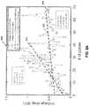
- FIG. 9Bis an illustrative graph of energy delivered as a function of pulse number for a static (constant polarity) shock wave device and a switching (alternating polarity) shock wave device.
- the electrical energy delivered by the polarity-switching shock wave deviceis higher on average per pulse and decays less than the energy delivered to the constant polarity device.
- the electrical energy deliveredmay be positively correlated with shock wave strength.
- the second electrode 104 illustrated in FIGS. 1B and 1Cmay have a cylindrical or ring shape, similar to that depicted in FIG. 6C as discussed in further detail below.
- FIGS. 1B and 1Cdepict a flattened second electrode 104 to illustrate the different voltage polarities that may be applied to the electrode assembly 100.
- the controller 120may output one or more positive pulses in a first direction 112 of current flow where the first wire 108 is coupled to a positive terminal of a voltage source 122 of the controller 120 and the first electrode 102, and the second wire 110 is coupled to a negative terminal of a voltage source of the controller 120 and the third electrode 106.
- the application of the voltage pulsecreates a plasma in the fluid that extends across the electrode pairs and permits conduction of the current.
- the currentthen flows from the first electrode 102 to second electrode 104, and then to third electrode 106.
- Plasma formationthus creates two electrode pairs connected in series.
- the positive terminal first electrode 102may experience a higher rate of wear than the negative terminal third electrode 106 when receiving a positive pulse from the controller 120.
- a negative terminal first electrode 102may deplete less material than the positive terminal third electrode 106 when receiving a negative pulse in a second direction 116 of current flow from a voltage source 122 of the controller 120.
- the controller 120may cause a current to flow in a first direction 112 for some of the pulses ( FIG. 1B ) and in a second direction 116 opposite the first direction 112 for the other pulses ( FIG. 1C ).
- the electrode assembly 100may form a greater number of shock waves with improved consistency before one or both of the smaller electrodes (102, 106) are depleted and the electrode assembly 100 fails.
- the first electrode 102 and the third electrode 106will have opposite voltage polarities no matter the direction of current flow. Therefore, the strength of the shock waves formed by the first electrode pair and the second electrode pair will differ for every pulse.
- the conductive region of the first electrode 102 and the third electrode 106may be smaller than the conductive region of the second electrode 104. Accordingly, the first electrode pair receiving the positive pulse 112 ( FIG. 1B ) may generate a stronger shock wave than the second electrode pair. Similarly, the first electrode pair receiving the negative pulse 116 may generate a weaker shock wave than the second electrode pair.
- the average shock wave strength output by the first electrode pair and the second electrode pairmay be more uniform to reduce variability. This may provide more consistent and predictable treatment by the shock wave device such that a practitioner may not need to align the shock wave device in vasculature based on differences shock wave strength between electrode pairs.
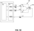
- FIG. IDis a block diagram of another variation of a controller 120 coupled to the electrode assembly 100.
- the electrode assembly 100may comprise a first electrode 102, second electrode 104, and a third electrode 106.
- the first electrode 102 and second or common electrode 104form a first electrode pair, and the third electrode 106 and the second electrode 104 form a second electrode pair.
- a first direction of current flow 112 of an energy pulsemay be delivered to the electrode assembly 100 by a voltage source 122 of the controller 120.
- the controller 120may cause other pulses delivered to the electrode assembly 100 to have a second direction of current flow 116 opposite the first direction 112 through the electrode assembly 100.
- the voltage polarity switch 124 of the controller 120may select a direction of current flow, and thus the voltage polarity of the electrodes, for each pulse delivered to the electrode assembly 100.
- the first electrode 102may be connected to a first voltage output terminal V01 of a voltage source 122 of the controller 120 by first wire 108
- the third electrode 106may be connected to a second voltage output terminal V02 of a voltage source 122 of the controller 120 by a second wire 110
- the second electrode 104may be connected to a third voltage output terminal V03 (ground channel) of a voltage source 122 of the controller 120 by a third wire 114.
- the first voltage output terminal VO1 and the second voltage output terminal VO2may be positive channels while the third voltage output terminal VO3 may be a negative channel for some of the pulses.
- the controller 120may also set the first voltage output terminal VO1 and the second voltage output terminal VO2 to be negative channels while the third voltage output terminal VO3 may be a positive channel for the remaining pulses.
- first and/or second voltage output terminals VO1, VO2current may flow in the first direction 112 or the second direction 116 over the first wire 108 and/or second wire 110 to respective first electrode 102 and third electrode 106.
- the voltage source 122 of controller 120may apply a positive or negative pulse on output terminal VO1 such that the potential difference between the first electrode 102 and the second electrode 104 is large enough to form a plasma arc between them, generating a bubble that gives rise to a shock wave.
- the voltage source of the controller 120may simultaneously or sequentially apply a positive or negative energy pulse on output terminal VO2 such that the potential difference between the third electrode 106 and the second electrode 104 is large enough to form a plasma arc between them, generating a bubble that gives rise to a different shock wave.
- a first shock wave formed between the first electrode 102 and the second electrode 104 and a second shock wave formed between the third electrode 106 and the second electrode 104may be formed simultaneously.
- the shock waves generated by the first and second electrodes pairsmay propagate in opposite directions, extending outward from the sides of a shock wave device.
- the current that traverses the bubble from the first electrode 102 and/or the third electrode 106 to the second electrode 104may return via third wire 114 to voltage output terminal VO3 (which may be a ground channel).
- Voltage output terminals VO1 and VO2may be independently addressed (e.g., voltage and current may be applied to one output but not necessarily the other), or may not be independently addressed (e.g., activating one output necessarily activates the other).
- FIG. 2Ais a block diagram of a controller 220 coupled to the first and second electrode assemblies 200, 250.
- the first electrode 202 and the first common electrode 206form a first electrode pair that may generate a first shock wave
- the second electrode 204 and the first common electrode 206form a second electrode pair that may generate a second shock wave.
- the third electrode 252 and the second common electrode 256form a third electrode pair that may generate a third shock wave
- the fourth electrode 254 and the second common electrode 256form a fourth electrode pair that may generate a fourth shock wave.
- the first, second, third, and fourth electrode pairsmay be connected in a series configuration and receive a series of pulses.
- a first direction of current flow 214 of some of the pulses in the seriesmay be delivered to the first and second electrode assemblies 200, 250 by a voltage source 222 of the controller 220.
- the controller 220may cause the remaining pulses in the series that are delivered to the first and second electrode assemblies 200, 250 to have a second direction 216 of current flow through the electrode assemblies 200, 250.
- a voltage polarity switch 224 of the controller 220may select a direction of current flow, and thus the voltage polarity of the electrodes, for each pulse delivered to the electrode assemblies 200, 250.
- the voltage polarity switch 224may switch a polarity of the first electrode 202 and fourth electrode 254 between positive and negative, where the first electrode 202 and fourth electrode 254 have opposite polarities.
- the controllermay cause current to flow through the electrode pair in a first direction for some of the pulses in the series and in a second direction opposite the first direction for the remaining pulses in the series.
- a first direction of current flowmay be provided for at least one of the pulses.
- a first direction of current flowmay be provided for at least about 5% of the pulses.
- a first direction of current flowmay be provided for at least about 10% of the pulses.
- a first direction of current flowmay be provided for at least about 15% of the pulses.
- a first direction of current flowmay be provided for at least about 20% of the pulses.
- a first direction of current flowmay be provided for at least about 25% of the pulses. In another variation, a first direction of current flow may be provided for at least about 30% of the pulses. In yet another variation, a first direction of current flow may be provided for at least about a third of the pulses. In another variation, a first direction of current flow may be provided for at least about 40% of the pulses. In another variation, a first direction of current flow may be provided for at least about 45% of the pulses. In still another variation, a first direction of current flow may be provided for at least about half of the pulses.
- the ratio of current flow of the pulses in the first direction to the second directionmay be about 1:6. In another variation, the ratio of current flow of the pulses in the first direction to the second direction may be about 5:6. In another variation, the ratio of current flow of the pulses in the first direction to the second direction may be about 1:8. In another variation, the ratio of current flow of the pulses in the first direction to the second direction may be about 3:8. In another variation, the ratio of current flow of the pulses in the first direction to the second direction may be about 5:8. In another variation, the ratio of current flow of the pulses in the first direction to the second direction may be about 7:8.
- the ratio of current flow of the pulses in the first direction to the second directionmay be about 1:9. In another variation, the ratio of current flow of the pulses in the first direction to the second direction may be about 2:9. In another variation, the ratio of current flow of the pulses in the first direction to the second direction may be about 4:9. In another variation, the ratio of current flow of the pulses in the first direction to the second direction may be about 5:9. In another variation, the ratio of current flow of the pulses in the first direction to the second direction may be about 7:9. In another variation, the ratio of current flow of the pulses in the first direction to the second direction may be about 8:9. In another variation, the ratio of current flow of the pulses in the first direction to the second direction may be about 1:12. In another variation, the ratio of current flow of the pulses in the first direction to the second direction may be about 1:16. In another variation, the ratio of current flow of the pulses in the first direction to the second direction may be about 1:32.
- the number of pulses in each direction of current flowmay be determined based on a desired longevity of the shock wave device, shock wave uniformity, shock wave energy, material properties, electrode gap distance, fluid conductivity, and so forth.
- the direction of current flowmay be switched according to the ratio of pulses in the first direction to the second direction.
- the direction of current flowmay vary randomly for each pulse so long as the total number of pulses maintains a predetermined ratio of current flow direction.
- shock waves output from the first through fourth electrode pairsmay have more uniform strength on average as polarity switching allows each electrode pair to receive positive pulses. This allows more predictable results, with a greater amount of electrical energy delivered to each electrode pair, which may facilitate the generation of stronger shock waves.
- a shock wave devicemay be able to more uniformly apply mechanical forces/pressures regardless of its orientation within the vasculature.
- the first and second common electrodes 206, 256 illustrated in FIG. 2Amay in some variations have a cylindrical or ring shape, similar to that depicted in FIG. 6C as discussed in further detail below.
- FIG. 2Bdepicts flattened first and second common electrodes 206, 256 to illustrate the different voltage polarities that may be applied to the first and second electrode assemblies 200, 250.
- a voltage source 222 of the controller 220may output one or more pulses where the first wire 208 is coupled to a positive terminal VO1 of controller 220 and the third wire 212 is coupled to a negative terminal VO2 of controller 220.
- the second electrode 204may be connected to the third electrode 252 via a second wire 210 (e.g., an interconnect wire).
- the first and second electrode assemblies 200, 250receive a positive pulse where the first and third electrode pairs generate stronger shock waves than the second and fourth electrode pairs.
- a voltage source 222 of the controller 220may output one or more pulses where the first wire 208 is coupled to a negative terminal VO1 of controller 220 and the third wire 212 is coupled to a positive terminal VO2 of controller 220.
- the first and second electrode assemblies 200, 250receive a negative pulse where the second and fourth electrode pairs generate the stronger shock waves. Therefore, in order to distribute the wear between the electrodes of the first and second electrode assemblies 200, 250 more evenly, the voltage polarity switch 224 of the controller 220 may cause a current to flow in a first direction for some of the pulses in a series of pulses and in a second direction opposite the first direction for the remaining pulses in the series.
- the electrode assemblies 200, 250may form a greater number of shock waves before one or more of the smaller inner electrodes (202, 204, 252, 254) are depleted, as well as more uniform shock waves propagated on average from the electrode assemblies (200, 250).
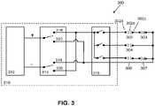
- FIG. 3is an illustrative block diagram of a variation of a shock wave system 300 comprising a first electrode assembly 302, a second electrode assembly 303, a third electrode assembly 304, fourth electrode assembly 306, and fifth electrode assembly 307.
- the first electrode assembly 302may comprise a first electrode 302a, second electrode 302b, and a third electrode 302c having a structure analogous to first electrode 102, second electrode 104, and third electrode 106, respectively, as depicted in FIGS. 1A and 1B .
- the conductive surface areas of the first electrode 302a and third electrode 302cmay be smaller relative to the conductive surface areas of the second electrode 302b.
- the larger electrode 302bmay comprise individual electrodes connected by, for example, an interconnect wire.
- the second through fifth electrode assemblies 303, 304, 306, and 307may comprise a similar configuration of electrodes as first electrode assembly 302.
- the first and second electrode assemblies 302 and 303are connected in series.
- the fourth and fifth electrode assemblies 306, 307are connected in series.
- the electrode assemblies 302, 303, 304, 306, and 307are switchably connected in parallel to a controller 310.
- the controller 310may comprise a voltage source 312 to deliver pulses to the electrode assemblies 302, 303, 304, 306, and 307.
- a multiplexer 316 of the controller 310may selectively activate first and second electrode assemblies 302 and 303, third electrode assembly 304, and fourth and fifth electrode assemblies 306 and 307.
- the multiplexer 316may be configured to selectively connect the voltage source 312 across the parallel electrode assembly lines individually, one at a time, or in any combination.
- the controller 310may further comprise a voltage polarity switch 314 configured to provide a first direction of current flow corresponding to a first switch position 318 and a second direction of current flow opposite the first direction, the second direction corresponding to a second switch position 320.
- the voltage source 312outputs a predetermined voltage pulse to the voltage polarity switch 314.
- a direction of current flowis selected between a first direction of current flow and a second direction opposite the first direction.
- the multiplexer 316may receive the energy pulse in either the first direction or the second direction, and then selectively deliver a series of pulses, having the current flow direction selected by the voltage polarity switch 314, to the electrode assemblies 302, 303, 304, 306, and 307 as illustrated in the timing diagram of FIG. 4 .
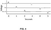
- FIG. 4is an illustrative timing diagram of a variation of a shock wave system 300 for selectively coupling electrodes to a power source with a selectively delivered direction of current.
- the controller 310may activate the different sets of electrode assemblies sequentially (e.g., one at a time) at a first voltage polarity and then activate the different sets of electrode assemblies sequentially at a second voltage polarity. This reserves all of the high voltage for each shock wave source to thus form shock waves of maximum strength to be applied to the calcium deposits all along the vasculature.
- the voltage polarity of an electrode assemblymay vary pulse to pulse, every second pulse, every third pulse, and is not particularly limited.
- the voltage polaritymay vary randomly. For example, for a set of 50 pulses being split evenly between a first voltage polarity (e.g., positive pulse) and a second voltage polarity (e.g., negative pulse), the voltage polarity need not switch every pulse.
- 8 pulses at the first voltage polaritymay be followed by 5 pulses at the second voltage polarity, then 7 pulses at the first voltage polarity, 5 pulses at the second voltage polarity, 10 pulses at the first voltage polarity, and 15 pulses at the second voltage polarity. Accordingly, while the total number of pulses is split evenly between the first and second voltage polarities, the number of switches in polarity does not necessarily depend on the current flow ratio.
- a multiplexermay be coupled to one or more of the electrode assemblies 302, 303, 304, 306, and 307, as depicted in FIG. 3 .
- any of the voltage polarity switching sequences discussed hereinmay be incorporated with the multiplexer 316.
- the selection of voltage polaritymay be independent of the electrode assembly selected by a multiplexer. Alternating polarity and timing may provide the dual benefits of distributing positive pulse wear over multiple electrodes and increasing rest time for the electrode assemblies.
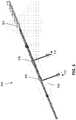
- FIG. 5depicts the distal portions of a shock wave device having two electrode assemblies 506, 508.
- FIG. 5depicts the distal portions of a shock wave device having two electrode assemblies 506, 508.
- FIG. 5depicts one variation of a shock wave device 500 comprising an elongate member 502, a first electrode assembly 506 at a first location along the length of the elongate member 502, a second electrode assembly 508 at a second location along the length of the elongate member 502, and optionally, an enclosure 504 configured to be fillable with a conductive fluid to sealably enclose the first and second electrode assemblies 506, 508.
- the enclosuremay comprise a membrane and/or a balloon may be made of an electrically insulating material that may be non-compliant (e.g., PET, etc.), semi-compliant (e.g., PBAX, nylon, PEBA, polyethylene, etc.), and/or compliant (e.g., polyurethane, silicone, etc.).
- the enclosure 504may enclose any number of electrode assemblies.
- the shock wave device 500may comprise a fluid lumen (not shown) that is in communication with a fluid source that introduces a conductive fluid into the enclosure 506.
- a voltage source(not shown) having a first terminal 510 and a second terminal 512 may be coupled to the shock wave device 500.
- the polarity of the terminals 510, 512may vary per pulse or in a predetermined sequence.
- An energy pulsemay be applied to the electrode pairs 506, 508, thereby generating one or more shock waves that may propagate through the fluid to impinge on a calcified obstruction.
- the shock wave device 500 in FIG. 5is depicted as having two electrode pairs 506, 508, it should be understood that other variations may have a different number of electrode pairs (e.g., 3, 4, 5, 6 or more electrode pairs).
- the electrode assemblies 506, 508each may comprise two inner electrodes that are positioned circumferentially opposite each other, an insulating sheath with two openings aligned over the two inner electrodes, and an outer common electrode with two openings that are coaxially aligned with the two openings of the insulating sheath.
- FIGS. 6A-6Cillustrate one variation of an electrode assembly in this configuration including two inner electrodes and an outer common electrode.
- Each of the electrode assemblies 506, 508may be configured to generate a pair of directed shock waves, where the shock waves resulting from a high voltage pulse to the first inner electrode propagate in a direction that is opposite to the direction of the shock waves resulting from a high voltage pulse to the second inner electrode.
- the electrode assemblies 506, 508may generate shock waves that propagate outward from different locations around the circumference of elongate member 502.
- the electrode assembly 506may generate shock waves that propagate from the left and right longitudinal side of the elongate member, while the electrode assembly 508 may generate shock waves that propagate from the top and bottom longitudinal side of the elongate member 502.
- the electrode assembly 506may generate a pair of shock waves that propagate outward from positions at 0 degrees and 180 degrees around the circumference of the elongate member 502, while the electrode assembly 508 may generate a pair of shock waves that propagate outward from positions at 60 degrees and 240 degrees around the circumference of the elongate member.
- electrode assemblies 506, 508may each generate a pair of shock waves that propagate outward at the same locations around the circumference of the elongate member, but from different locations along the length of the elongate member.
- one or more radiopaque marker bandsmay be provided along the length of the elongate member to allow a practitioner to identify the location and/or orientation of the shock wave device 500 as it is inserted through the vasculature of a patient.
- shock wave devices with a plurality of electrode assemblies distributed along the length of a cathetermay be suitable for use in angioplasty procedures to break up calcified plaques that may be located along a length of a vessel.
- Shock wave devices with a plurality of electrode assemblies along the length of a curved elongate membermay be suitable for use in valvuloplasty procedures to break up calcified plaques that may be located around the circumference of a valve (e.g., at or around the leaflets of a valve).
- FIG. 2A and the simplified layout of FIG. 2Bcorrespond electrically to FIG. 5 embodiment, when the electrode assemblies 506, 508 each include two electrode pairs as shown in FIG. 6 .
- FIGS. 6A-6Bdepict top and bottom views, respectively, of one variation of a shock wave device having an electrode assembly 600 that may be configured to generate shock waves in opposite directions.
- FIG. 6Ais a top view of the electrode assembly 600 where the first inner electrode 602 is depicted
- FIG. 6Bis a bottom view of the electrode assembly 600 where the second inner electrode 604 is depicted.
- the first and second inner electrodesshare a common electrode 606 and are located circumferentially opposite each other (i.e., 180 degrees apart).
- the first electrode 602may be connected to a first voltage output terminal VO1 of a voltage source of a controller (not shown in FIGS.
- first wire 608 and the second electrode 604may be connected to a second voltage output terminal V02 of a voltage source of the controller by a second wire 610.
- the first electrode 602 and the common electrode 606form a first electrode pair that may generate a first shock wave that propagates outwards in a first shock wave direction
- the second electrode 604 and the common electrode 606form a second electrode pair that may generate a second shock wave that propagates outwards in a second shock wave direction that is opposite to the first shock wave direction.
- a positive pulse provided in a first current direction 616current flows from the first electrode pair to the second electrode pair.
- a negative pulse provided in a second current direction 618 opposite the first current direction 616current flows from the second electrode pair to the first electrode pair.
- a difference in surface area of conductive regions within an electrode pairmay be provided to generate larger shock waves.
- the surface area of the edges of the first electrode 602 and the second electrode 604may serve as conductive regions, and may be the portions of the electrodes which are most likely to wear due to high energy pulses.
- An electrode such as the common electrode 606may form two conductive regions for each of the first and second electrodes 602, 604 having different surface areas.
- a surface area of a conductive region of the first electrode 602 and second electrode 604may be smaller in surface area relative to the common electrode 606. Therefore, the longevity of the electrode assembly 600 may depend on the rate of depletion of the smaller electrodes 602, 604.
- the degree of erosion and wearmay be determined by measuring one or more of voltage drop, voltage pulse width, low voltage analogs of voltage pulse width, and/or any signals that indicate (or are correlated with) the duration of a high-voltage pulse across an electrode pair.
- FIG. 6Cdepicts a perspective view of the outer common electrode 606.
- first opening 612may be located directly across from second opening 614.
- the outer common electrode 606may have the second opening 614 coaxially aligned over the second inner electrode, and the first inner electrode 604 may be coaxially aligned with the first opening 612 of the outer common electrode 606.
- This configurationmay generate a first shock wave that propagates outwards in a first direction and a second shock wave that propagates outwards in a second direction that is opposite to the first direction.
- the wires 608, 610may be electrically insulated along their length (e.g., by an insulating coating or sheath made of, for example, polyimide, PEBA, PET, FEP, PTFE, etc.) except for one or more regions where the electrically conductive core of the wire is exposed to contact a portion of the inner and/or outer electrode.
- the wires 608, 610may be made of any conductive material, for example, free oxygen copper or copper or silver.
- FIGS. 7A-7Bdepict top and bottom views of one variation of a shock wave device having a first electrode assembly 700 and a second electrode assembly 750 that may be configured to generate shock waves along a length of the shock wave device.
- the electrode assemblies 700, 750may be connected in series with respect to each other such that activating a first electrode assembly 700 also activates a second electrode assembly 750.
- reducing the number of wires that extend along the length of the elongate membermay allow the elongate member to bend and flex more freely as it is advanced through the vasculature of a patient (e.g., may allow for a tighter turning radius).
- FIG. 7Ais a top view of the electrode assemblies 700, 750 where the first inner electrode 706 and the fourth inner electrode 754 are depicted.
- FIG. 7Bis a bottom view of the electrode assemblies 700, 750 where the second inner electrode 704 and the third inner electrode 752 are depicted.
- the first and second inner electrodes 702, 704share a first common electrode 706 and are located circumferentially opposite each other (i.e., 180 degrees apart).
- the third and fourth inner electrodes 752, 754share a second common electrode 756 and are also located circumferentially opposite each other.
- the inner electrodes and electrode assembliesmay be offset from each other in some other manner as described above.
- the first electrode 702 and the first common electrode 706form a first electrode pair that may generate a first shock wave that propagates outwards in a first direction
- the second electrode 704 and the first common electrode 706form a second electrode pair that may generate a second shock wave that propagates outwards in a second direction
- the third electrode 752 and the second common electrode 756form a third electrode pair that may generate a third shock wave that propagates outwards in a third direction
- the fourth electrode 754 and the second common electrode 756form a fourth electrode pair that may generate a fourth shock wave that propagates outwards in a fourth direction.
- the first and second electrode assemblies 700, 750 in FIGS. 7A-7Bmay be connected in series.
- the first electrode 702may be connected to a first voltage output terminal V01 of a voltage source of a controller (not shown in FIGS. 7A-7B ) by a first wire 708.
- the second electrode 704may be connected to the third electrode 752 via a second wire 710 (e.g., an interconnect wire).
- the fourth electrode 754may be connected to a second voltage output terminal V02 of the voltage source of the controller by a third wire 712. Therefore, for a positive pulse provided in a first current direction 714, current flows (in ascending order) from the first electrode pair to the fourth electrode pair.
- each of the first through fourth electrodes 702, 704, 752, 754may be smaller in size relative to the first and second common electrodes 706, 756.
- sizemay refer to the total size of the electrode and/or a surface area of a conductive region of the electrode. Therefore, the longevity of the electrode assemblies 700, 750 may depend on the rate of depletion of the smaller electrodes 702, 704, 752, 754.
- shock wave devices described hereinmay be provided in a shock wave system suitable for use in an angioplasty or valvuloplasty procedure.
- a shock wave systemmay include a shock wave device, catheter, a high voltage pulse generator (e.g., voltage source), and/or an enclosure configured to be fillable with a conductive fluid.
- the cathetermay have a guide wire lumen therethrough.
- the high voltage pulse generatormay be a 0.1 kV to 10 kV pulsed power supply, for example, a 2 kV to 6 kV pulsed supply.
- shock wave devices described hereinmay be used in an angioplasty and/or valvuloplasty procedure.
- the methods described heremay include advancing a guide wire from an entry site on a patient (e.g., an artery in the groin area of the leg) to a target region of a vessel (e.g., a region having calcified plaques that need to be broken up.
- a shock wave devicemay comprise an axially extending elongate member with a guide wire lumen, an electrode pair comprising a first electrode and a second electrode and/or an electrode assembly provided along a length of the elongate member.
- the electrode pair and/or electrode assemblymay be any of the electrodes described herein.
- a balloonmay be collapsed over the elongate member while the device is advanced through the vasculature.
- the location of the shock wave devicemay be determined by x-ray imaging and/or fluoroscopy.
- the balloonmay be filled with a conductive fluid (e.g., saline and/or saline mixed with an image contrast agent).
- a series of pulsesmay be delivered to the first electrode pair and/or electrode assembly to create shock waves that may break up calcified plaque, for example.
- a first direction of current flowmay be provided for at least one of the pulses.
- a first direction of current flowmay be provided for at least about 5% of the pulses.
- a first direction of current flowmay be provided for at least about 10% of the pulses.
- a first direction of current flowmay be provided for at least about 15% of the pulses.
- a first direction of current flowmay be provided for at least about 20% of the pulses.
- a first direction of current flowmay be provided for at least about 25% of the pulses. In another variation, a first direction of current flow may be provided for at least about 30% of the pulses. In yet another variation, a first direction of current flow may be provided for at least about a third of the pulses. In another variation, a first direction of current flow may be provided for at least about 40% of the pulses. In another variation, a first direction of current flow may be provided for at least about 45% of the pulses. In still another variation, a first direction of current flow may be provided for at least about half of the pulses.
- the ratio of current flow of the pulses in the first direction to the second directionmay be about 1:6. In another variation, the ratio of current flow of the pulses in the first direction to the second direction may be about 5:6. In another variation, the ratio of current flow of the pulses in the first direction to the second direction may be about 1:8. In another variation, the ratio of current flow of the pulses in the first direction to the second direction may be about 3:8. In another variation, the ratio of current flow of the pulses in the first direction to the second direction may be about 5:8. In another variation, the ratio of current flow of the pulses in the first direction to the second direction may be about 7:8.
- the ratio of current flow of the pulses in the first direction to the second directionmay be about 1:9. In another variation, the ratio of current flow of the pulses in the first direction to the second direction may be about 2:9. In another variation, the ratio of current flow of the pulses in the first direction to the second direction may be about 4:9. In another variation, the ratio of current flow of the pulses in the first direction to the second direction may be about 5:9. In another variation, the ratio of current flow of the pulses in the first direction to the second direction may be about 7:9. In another variation, the ratio of current flow of the pulses in the first direction to the second direction may be about 8:9. In another variation, the ratio of current flow of the pulses in the first direction to the second direction may be about 1:12.
- the ratio of current flow of the pulses in the first direction to the second directionmay be about 1:16. In another variation, the ratio of current flow of the pulses in the first direction to the second direction may be about 1:32.
- the number of pulses in each direction of current flow(e.g., ratio of current flow of first direction to second direction) may be determined based on a desired longevity of the shock wave device, shock wave uniformity, shock wave energy, and so forth.
- the number of transitions of current flow directionsis not particularly limited.
- the direction of current flowmay be switched according to the ratio of pulses in the first direction to the second direction.
- the direction of current flowmay vary randomly for each pulse so long as the total number of pulses maintains a predetermined ratio of current flow direction. Accordingly, the current flow direction need not switch for every pulse even if the number of pulses in each direction is equal. Alternating on average the direction of current flow of the pulses may about double the durability of the smaller electrodes, and thus the lifetime of the electrode assembly. Even when the electrodes in an electrode pair are of equal size, alternating the direction of current flow so that each electrode receives about the same number of positive pulses will distribute the wear over two electrodes so as to about double the electrode pair durability.
- shock waves output from different electrode pairsmay have more uniform strength on average as polarity switching allows each electrode pair to receive the positive pulse. This allows more predictable shock waves with less variance in shock wave strength.
- the progress of the plaque break-upmay be monitored by x-ray and/or fluoroscopy.
- the shockwave devicemay be moved along the length of the vessel if the calcified region is longer than the length of the elongate member with the electrode assemblies, and/or if the calcified region is too far away from the electrode assemblies to receive the full force of the generated shock waves.
- the shockwave devicemay be stepped along the length of a calcified vessel region to sequentially break up the plaque.
- Voltage and current measurementsmay be taken at the load (in this case, the electrode assembly) to determine the condition of the shock wave device as the pulses are delivered. As discussed in further detail below, measurements including voltage drop, voltage pulse width, and current flow may be used to determine a condition/longevity of the shock wave device.
- polarity switching of the pulsesmay be based on the condition of the electrodes in a shock wave device.
- the direction of current flow of pulses in a seriesmay be determined using measurements correlated to voltage drop, such as voltage pulse width, which may be correlated to the condition of the electrodes. For instance, a first voltage pulse width across the electrode pair may be measured for a first direction of current flow and a second voltage pulse width across the electrode pair may be measured for a second direction of current flow. A difference (if any) between the first voltage pulse width and the second voltage pulse width may indicate a difference in electrode wear. In some cases, differences in the degree of electrode erosion between the electrodes in a pair may lead to a shorter lifespan of the overall shock wave device. By switching the direction of current flow based on the measured voltage pulse widths to balance the wear between the first and second electrodes, the lifetime of a shock wave device may be prolonged.
- the direction of current flow for pulses in a seriesmay be selected according to the measured voltage pulse widths. For instance, the direction of current flow may be selected such that a difference between the voltage pulse width across the electrode pair when the current flows in a first direction and the voltage pulse width when the current flows in a second direction are within a predetermined threshold. In other variations, the direction of current flow may be selected such that the voltage pulse width across the electrode pair when the current flows in a first direction is substantially equal to the voltage pulse width across the electrode pair when the current flows in a second direction.
- the ratio of current flow of the pulses in a first direction to a second (opposite) directionmay be determined at least in part by the measured voltage pulse width. For example, if the measured voltage pulse width in the first direction of current flow (i.e., first polarity) meets or exceeds a predetermined threshold, the controller may determine that the first electrode of the electrode pair has a greater degree of erosion than the second electrode of the electrode pair. The controller may then adjust the polarity ratio so that the second direction of current flow (i.e., second polarity) is increased relative to the first direction of current flow. This may help reduce or stabilize the erosion rate of the first electrode so that the overall electrode pair may be more durable (e.g., longer lifespan) as compared to a shock wave system where the polarity is not switched and/or polarity ratio is not adjusted.
- the electrode assemblies of the shock wave devicemay be connected in series, and may be activated simultaneously and/or sequentially, as described above.
- a pair of electrode assembliesmay be connected in series and activated simultaneously or sequentially.
- the balloonmay be inflated further or deflated, and the shock wave device and guide wire may be withdrawn from the patient. Wear of the shock wave device may be evaluated through visual inspection by microscopy.
- test resultsare provided for electrodes to compare electrical energy delivery to a set of electrodes receiving using a constant polarity (static device) for every pulse and alternating polarity as described above (switching device). Electrical current, voltage, energy measurements, and visual inspection as a function of pulses were taken of an 8 gap copper coil emitter to determine erosion, electrode integrity, and electrode lifetime.
- the shock wave deviceswere pulsed at 0.5 Hz or slower with a pulse width of about 6 ⁇ s.
- FIG. 8Ais an illustrative graph of voltage drop (kV) as a function of pulse number. Voltage drop is defined as the difference between the highest and lowest voltage prior to current flow (representing voltage losses which are correlated to electrode wear). As shown in FIG. 8A , voltage drop increases as a function of pulse number. However, static energy delivery has a much larger rate of voltage drop compared to switching energy delivery indicating more electrode wear. FIG. 8A illustrates the rate of voltage drop (slope a) having a linear best fit (R). From the linear best fits, the voltage losses represented by the voltage drop (kV) increase at a much faster rate 800 for static energy compared to the rate 802 for switching energy. It should be noted that the static shock wave device fails 804 at about 40 pulses before the switching shock wave device fails at about 70 pulses.
- FIGS. 8B and 8Care illustrative graphs comparing voltage drop as a function of pulse width for a non-switching electrode assembly and a switching electrode assembly, respectively.
- line 808represents the high correlation fit between voltage drop and pulse width for a non-switching shock wave device.
- line 810illustrates a high correlation fit between voltage drop and pulse width for a polarity switching shock wave device.
- the width of each pulse(e.g., voltage, current) is defined herein as the first time and the last time the pulse reaches 20% of the maximum voltage peak value. Similar to voltage drop (kV), the voltage pulse width increases as a function of pulse number and is an indicator of electrode degradation. In other words, measurement of voltage pulse width may be used as a proxy for voltage drop to monitor the condition (e.g., degradation) of an electrode pair. That is, the longer the measured voltage pulse width, the more the electrode with the positive polarity has eroded or degraded. Alternatively, measurement of an internal signal that indicates the onset and offset of a high voltage pulse across an electrode pair may be used to monitor the condition of the electrodes. For example, the internal signal may be a trigger TTL output signal of the high voltage pulse generator.
- FIG. 9Ais an illustrative graph of pulse number as a function of voltage polarity.
- FIG. 9Bis an illustrative graph of energy delivered as a function of pulse number. Since more pulses may be provided to a switching device than a static device, the lifetime of the switching device may be about double that of the static device. In FIG. 9B , it is apparent that the number of pulses and the average amount of energy delivered by the switching device is significantly more than the static device due to polarity switching. For instance, the static device provides about 40 pulses before static device failure 900 while the switching device provides about 70 pulses before switching device failure 902.
- the test resultsindicate that switching current flow direction may increase the lifetime and energy delivered of an 8 gap shock wave device over a constant current flow direction 8 gap shock wave device.
- Visual inspectionalso shows biased wear of the electrodes when a single direction of current flow is applied compared to alternating current flow.
- Experimental testinghas shown that the voltage pulse width is directly proportional to energy voltage drop prior to current flow. Therefore, a static device has more voltage loss compared to a switching device.
- the voltage pulse widthmay be used as a metrology tool to monitor the lifetime and/or condition of a shock wave device from pulse to pulse. Thus, switching the direction of current flow may improve the efficiency and/or consistency of shock waves output by a shock wave device.
Landscapes
- Health & Medical Sciences (AREA)
- Engineering & Computer Science (AREA)
- Life Sciences & Earth Sciences (AREA)
- Surgery (AREA)
- Biomedical Technology (AREA)
- Medical Informatics (AREA)
- Orthopedic Medicine & Surgery (AREA)
- Vascular Medicine (AREA)
- Nuclear Medicine, Radiotherapy & Molecular Imaging (AREA)
- Mechanical Engineering (AREA)
- Veterinary Medicine (AREA)
- Public Health (AREA)
- General Health & Medical Sciences (AREA)
- Molecular Biology (AREA)
- Heart & Thoracic Surgery (AREA)
- Animal Behavior & Ethology (AREA)
- Structural Engineering (AREA)
- Civil Engineering (AREA)
- Architecture (AREA)
- Plasma Technology (AREA)
- Surgical Instruments (AREA)
Description
- The current invention relates to devices for producing shock waves. The devices may be used for angioplasty and/or valvuloplasty procedures
- Currently, angioplasty balloons are used to open calcified lesions in the wall of an artery. However, as an angioplasty balloon is inflated to expand the lesion in the vascular wall, the inflation pressure stores a tremendous amount of energy in the balloon until the calcified lesion breaks or cracks. That stored energy is then released and may stress and injure the wall of the blood vessel.
- Electrohydraulic lithotripsy has been typically used for breaking calcified deposits or "stones" in the urinary or biliary track. Lithotripsy electrodes may similarly be useful for breaking calcified plaques in the wall of a vascular structure. Shock waves generated by lithotripsy electrodes may be used to selectively fracture a calcified lesion to help prevent sudden stress and injury to the vessel or valve wall when it is dilated using a balloon. It may therefore be useful to find improved ways to form shock waves in a balloon.
- European patent application with publication number
EP0082508 discloses a calculus disintegrating apparatus comprising a first and second electrode which are arranged at the distal end of a probe inserted into a coeliac cavity, and discharge energy sources connected to the first and second electrodes to impress DC impulse voltage across them. - US patent number
US5,540,682 discloses an electrosurgery apparatus having a processor that generates a data stream output representing characteristics of the electrosurgery pulses to be generated. The data stream output comprises digitally-represented values indicative respectively of the width of each pulse, the duration of a first period during which pulses are to be generated, the duration of a second period during which pulses are not to be generated, the duration of a third period during which pulses are to be generated and the duration of a fourth period during which pulses are not to be generated. - US patent number
US9,011,463 - The invention relates to a shock wave device as specified in
independent claim 1. Further embodiments are defined in the dependent claims. Described here are devices and exemplary methods for forming a shock wave in an angioplasty or valvuloplasty procedure. Generally, a shock wave device described here comprises an axially extending elongate member. The elongate member comprises a first electrode pair comprising a first electrode and a second electrode. The electrode pair may be positioned within a conductive fluid. A controller is may coupled to the first electrode pair and is configured to deliver a series of individual pulses to the first electrode pair such that each of the pulses creates a shock wave in the conductive fluid. The controller causes current to flow through the electrode pair in a first direction for some of the pulses in the series and in a second direction opposite the first direction for the remaining pulses in the series. In some variations, the current may flow in the second direction for between twenty five percent and fifty percent of the pulses in the series. The shock wave devices and exemplary methods described herein may help facilitate the uniform and consistent delivery of energy to the electrodes, which may enhance the durability and performance of the electrodes. - In some variations, the controller may cause the current to flow in the second direction for between one third and half of the pulses in the series. In other variations, the controller may cause the current to flow in the second direction for at least about half of the pulses in the series.
- In some variations, the controller comprises a voltage polarity switch to switch a polarity of the electrodes between positive and negative. The electrodes may have opposite polarities. In other variations, a first surface area of a first conductive region of the first electrode is smaller than a second surface area of a second conductive region of the second electrode.
- In some variations, the controller comprises a voltage source. A first wire may connect the first electrode to a first terminal of the voltage source, and a second wire may connect the second electrode to a second terminal of the voltage source. In some instances, the first terminal is positive and the second terminal is negative in the first direction of current flow, and the first terminal is negative and the second terminal is positive in the second direction.
- In some variations, a second electrode pair is provided and the controller may further comprise a multiplexer configured to selectively deliver the series of pulses to the first electrode pair and the second electrode pair. In other variations, the device may further comprise a fluid enclosure surrounding the electrode pair. The fluid enclosure may comprise a balloon surrounding a portion of the elongate member. The balloon may be configured to be filled with a conductive fluid, and the first electrode pair may be enclosed within and spaced from the balloon.
- In yet other variations, the shock wave devices described here comprise an axially extending elongate member. The elongate member comprises a first electrode assembly comprising a first electrode pair and a second electrode pair. The first electrode assembly may be positioned within a conductive fluid. A controller is coupled to the first electrode assembly and configured to deliver a series of individual pulses to the first electrode assembly such that each of the pulses creates a shock wave in the conductive fluid. The controller causes current to flow through the electrode assembly in a first direction for some of the pulses in the series and in a second direction opposite the first direction for the remaining pulses in the series. In some instances, the current flows in the second direction for between twenty five percent and fifty percent of the pulses in the series.
- In some variations, the first electrode assembly may comprise a first electrode, a second electrode, and a common electrode. The first electrode pair may comprise the first electrode and the common electrode and the second electrode pair may comprise the second electrode and the common electrode. In some instances, the controller may comprise a voltage polarity switch to switch a polarity of the first electrode and the second electrode between positive and negative. The first electrode and the second electrode may have opposite polarities. In other instances, a first surface area of a first conductive region of the first electrode and a second surface area of a second conductive region of the second electrode may be different than a third surface area of a third conductive region of the common electrode. In some instances, the controller may comprise a voltage source where a first wire may connect the first electrode to a first terminal of the voltage source, and a second wire may connect the second electrode to a second terminal of the voltage source. In other instances, the controller may comprise a voltage source where a first wire may connect the first electrode to a first terminal of the voltage source, a second wire may connect the second electrode to a second terminal of the voltage source, and a third wire may connect the common electrode to a third terminal of the voltage source.
- In some variations, a second electrode assembly may be coupled in series to the first electrode assembly. In some instances, the controller may comprise a voltage source where a first wire may connect the first electrode assembly to a first terminal of the voltage source, a second wire may connect the first electrode assembly to the second electrode assembly, and a third wire may connect the second electrode assembly to a second terminal of the voltage source.
- In other variations, the device may comprise a second electrode assembly. The controller may further comprise a multiplexer that selectively delivers the series of pulses to the first electrode assembly and the second electrode assembly. In yet other variations, the device may further comprise a fluid enclosure surrounding the first electrode assembly. The fluid enclosure may comprise a balloon surrounding a portion of the elongate member. The balloon may be configured to be filled with a conductive fluid, and the first electrode assembly may be enclosed within and spaced from the balloon.
- In some variations, exemplary methods of forming shock waves described here may comprise advancing a shock wave device into a blood vessel. The shock wave device may comprise an axially extending elongate member. The elongate member may comprise a first electrode pair comprising a first electrode and a second electrode. The first electrode pair may be positioned within a conductive fluid. A series of individual pulses may be delivered to the first electrode pair to create shock waves in the conductive fluid to cause current to flow through the electrode pair in a first direction for some of the pulses in the series and in a second direction opposite the first direction for the remaining pulses in the series. In some variations, the current may flow in the second direction for between twenty five percent and fifty percent of the pulses in the series.
- In some variations, the current may flow in the second direction for between one third and half of the pulses in the series. In other variations, the current may flow in the second direction for at least about half of the pulses in the series. In some variations, a voltage pulse width may be measured to monitor a condition of the shock wave device. In some of these variations, the percentage of pulses that cause current to flow in the second direction may be adjusted according to the measured voltage pulse width.
FIGS. 1A-1D are illustrative depictions of a variation of an electrode assembly.FIGS. 1A and1D are block diagrams of variations of a controller coupled to an electrode assembly.FIGS. 1B and 1C are illustrative depictions of variations of a flattened electrode assembly.FIGS. 2A-2B are illustrative depictions of a variation of a series of electrode assemblies.FIG. 2A is a block diagram of a variation of a controller coupled to the series of electrode assemblies.FIG. 2B is an illustrative depiction of a variation of flattened electrode assemblies.FIG. 3 is an illustrative block diagram of a variation of a shock wave system comprising electrode assemblies, a controller, and a voltage source.FIG. 4 is an illustrative timing diagram of a variation of a shock wave system.FIG. 5 is a perspective view of another variation of a shock wave device.FIGS. 6A-6C are illustrative depictions of another variation of an electrode assembly.FIG. 6A is a top view andFIG. 6B is a bottom view of a variation of the electrode assembly.FIG. 6C is a perspective view of a variation of a common electrode.FIGS. 7A-7B are illustrative depictions of a variation of a series of electrode assemblies.FIG. 7A is a top view andFIG. 7B is a bottom view of a variation of the series of electrode assemblies.FIG. 8A is an illustrative graph comparing the voltage drop as a function of pulse number between switching and non-switching energy pulses.FIGS. 8B and 8C are illustrative graphs comparing voltage drop as a function of pulse width for a non-switching electrode assembly and a switching electrode assembly, respectively.FIG. 9A is an illustrative graph of pulse number as a function of voltage polarity.FIG. 9B is an illustrative graph of energy delivered at the electrode assembly as a function of pulse number between switching and non-switching energy pulses.- Described herein are devices and systems that comprise one or more shock wave electrodes that may be suitable for use in angioplasty and/or valvuloplasty procedures. Generally, shock wave electrodes are provided along an axially extending elongate member (e.g., catheter) and may be attached to a source of high voltage pulses, ranging from 0.1 kV to 10 kV for various pulse durations. In some variations, the electrodes may be surrounded by an enclosure carrying a conductive fluid (e.g., saline). In some variations, the enclosure may comprise a balloon surrounding a portion of the elongate member and configured to be filled with a conductive fluid, where the electrodes may be enclosed within and spaced from the balloon walls.
- A controller may be coupled to the first electrode pair to deliver a series of energy pulses to produce shock waves. The shock waves generated may disrupt calcified obstructions in an artery or a valve. One mechanism for shock wave formation is described below. When a high voltage is applied across a pair of electrodes located within the conductive fluid, a plasma arc may form between them, giving rise to a steam bubble in the fluid. A first shock wave may occur when the steam bubble first forms and a second shock wave may occur as the steam bubble collapses. Shock waves may be mechanically conducted through the fluid to apply mechanical force or pressure to break apart any calcified plaques on, or in, the vasculature walls.
- The size, rate of expansion, and collapse of the bubble (and therefore, the magnitude, duration, and distribution of the mechanical force) may vary based on the magnitude and duration of the voltage pulse. Furthermore, the timing and size of the bubble, along with the sonic output and propagation direction of the resultant shock waves, depend at least in part on the location, geometry, size, condition, and distances between the electrodes (electrode gap distance). For example, an increase in electrode gap distance decreases the corresponding sonic output. The size and arrangement of the electrodes may also impact the types of vascular structures that may be accessed and treated by a shock wave device. Shock wave electrodes may be made of materials that can withstand high voltage levels and intense mechanical forces (e.g., about 300-3000 psi or 20-200 ATM (about 2000 - 20000 kPa) in a few microseconds) that may be generated during use. For example, the electrodes may be made of stainless steel, tungsten, nickel, iron, steel, and the like.
- Generally, current flowing between a pair of electrodes in a conductive fluid causes movement of metal from the positive terminal to the negative terminal, eventually depleting the positive terminal electrode of material, and may be referred to as one-sided erosion when a direction of current flow is fixed. Shock wave electrodes may experience a high rate of wear and erosion with every pulse applied due to the necessarily high current (e.g., hundreds of amps) flowing through the fluid, heat generated by the plasma arc, and mechanical shock wave forces.
- The devices, systems, and methods described herein may help to reduce the rate of electrode wear to enhance electrode durability and shock wave consistency. The longevity of an electrode pair may depend on at least one of the following: polarity of a voltage pulse, length of a voltage pulse, magnitude of a voltage pulse, material properties, fluid conductivity, electrode gap distance between conductive regions of each of the electrodes in an electrode pair, and/or the surface area of the conductive region(s) of the electrodes in the pair. A longer pulse may increase the wear/erosion of an electrode pair as compared to a shorter pulse. In some variations where the electrode pair has different sized electrodes where one electrode has a smaller conductive region surface area than the other electrode, the electrode with the smaller conductive region may be more susceptible to erosion than the electrode with a larger conductive region. That is, the electrode with the smaller conductive region may erode at a greater rate than the electrode with the larger conductive region. The devices and methods described herein may help to even out the rate of erosion between the electrodes in an electrode pair, so that the electrodes erode at approximately the same rate. This may enhance the durability of the overall electrode pair, and may also facilitate uniform energy delivery to the electrode pair over a greater number of pulses.
- It should be appreciated that a shock wave device generates the strongest shock waves when the electrodes are dissimilar in size where the smaller electrode has a positive polarity and the larger electrode has a negative polarity. Thus, while an electrode pair having a small, positive terminal electrode and a large, negative terminal electrode may form the strongest shock wave, this combination of size and polarity may shorten the lifetime of the electrode pair. The problem of a short lifespan may not be a simple matter of increasing electrode size since the size of a shock wave device and electrodes may be limited by the size of the vasculature through which it is advanced. However, voltage polarity switching, as described in further detail below, may facilitate electrode longevity while maintaining electrode size such that the electrode can be navigated through vasculature. Additionally or alternatively, voltage polarity switching may facilitate a reduction in electrode size with a similar electrode longevity relative to a non-polarity switching device.
- Furthermore, the devices, systems, and methods described herein may facilitate the uniformity of shock wave intensity formed at different sites along a shock wave device. In some variations, a shock wave device may comprise a plurality of spaced apart electrode pairs connected in series. The shock waves generated by the electrode pairs may vary in strength even if the size and shape of the electrode pairs are the same. For instance, identical electrode pairs in series positioned 180 degrees apart from each other may form shock waves of varying strength from opposing sides of the device. This difference may be negligible for any single pulse. However, over a series of pulses, one side of the shock wave device may be more effective at cracking calcium deposits than the other side of the device. Voltage polarity switching, as described in further detail below, may facilitate the uniformity of shock wave intensity formed in different electrode pairs.
- For example, a controller may cause current to flow through an electrode pair in a first direction for some pulses and in a second direction that is opposite to the first direction for other pulses. As an example, the direction of current flow may vary pulse to pulse or every second pulse, and is not particularly limited. It should be noted that the pulses are outputted discretely such that there is an interval of time between pulses when current does not flow through a shock wave device. The duration of the interval of time may be pre-selected according to, for example, a desired rate or frequency of shock wave generation. Furthermore, each pulse has a single direction of current flow and does not switch within the pulse. For instance, a voltage polarity switch may switch only when current is not flowing to the shock wave device (i.e., the voltage polarity switch may only occur in the interval between voltage pulses, and not during a voltage pulse).
- Furthermore, the direction of current flow may vary randomly for each pulse so long as the total number of pulses maintain a predetermined current flow direction ratio. For example, for a set of 50 pulses being split evenly in the first direction and the second direction, the direction of current flow need not switch every pulse. As an illustrative example, 20 pulses in the first direction may be followed by 10 pulses in the second direction, then 3 pulses in the first direction, 15 pulses in the second direction, and 2 pulses in the first direction. Accordingly, while the total number of pulses is split evenly between the first and second direction, the number of switches in current flow does not necessarily correspond to the current flow ratio direction.
- In some variations, a single pulse may be provided in the second direction with the remaining pulses in the first direction, and vice-versa. This allows the electrode pair to produce shock waves with a greater number of pulses before failure relative to an electrode pair receiving pulses with a constant polarity. Durability may thus be improved by distributing the electrode wear of the positive pulse over both electrodes.
- In one variation, the current may flow in a first direction for about half of the pulses in the series and in the second, opposite direction for about the other half of the pulses in the series. In doing so, each electrode is set to be the positive terminal for about half of the pulses, thereby distributing the number of high erosion positive pulses experienced by any one of the electrodes about equally between the electrodes in the pair. The direction of current flow may be switched one or more times. In some cases, the electrode pair longevity may be about doubled relative to electrodes having a single direction of current flow, allowing more shock waves to be formed and/or the electrode pair to be formed smaller relative to electrodes having a single direction of current flow. Therefore, the shock wave devices described herein may be particularly useful in small arteries such as coronary arteries. Moreover, a shock wave device comprising a plurality of electrode pairs having pulses with current flow in both directions may facilitate the uniformity of shock wave intensity generated by the electrode pairs.
- Generally described here are shock wave devices for angioplasty and/or valvuloplasty procedures. The devices and methods described here may use one or more devices or elements described in
U.S. Patent No. 8,888,788 and titled "LOW PROFILE ELECTRODES FOR AN ANGIOPLASTY SHOCK WAVE CATHETER," and/or one or more devices or elements described inU.S. Patent No. 9,011,463 FIG. 1A is a block diagram of acontroller 120 coupled to anelectrode assembly 100.Electrode assembly 100 may comprise afirst electrode 102, asecond electrode 104, and athird electrode 106. Thefirst electrode 102 may be connected to a first voltage output terminal V01 of a voltage source of thecontroller 120 byfirst wire 108, thethird electrode 106 may be connected to a second voltage output terminal V02 of a voltage source of thecontroller 120 by asecond wire 110, and the second orcommon electrode 104 may be provided in series between thefirst electrode 102 andthird electrode 106. Upon application of a sufficient voltage pulse, a first plasma arc may form between thefirst electrode 102 and the second electrode 104 (i.e., a first electrode pair), and a second plasma arc may form between thesecond electrode 104 and the third electrode 106 (i.e., a second electrode pair). The first and second electrode pairs are connected in series, where thesecond electrode 104 is shared between the first and second electrode pairs. Althoughelectrode assembly 100 is described above as comprising three electrodes that form two electrode pairs, some variations of an electrode assembly may comprise two electrodes that form one electrode pair.- A first direction of
current flow 112 of an energy pulse may be delivered to theelectrode assembly 100 by avoltage source 122 of thecontroller 120. Thecontroller 120 may cause other pulses delivered to theelectrode assembly 100 to have asecond direction 116 of current flow that is the opposite direction of thefirst direction 112. Thecontroller 120 may select a direction of current flow, and thus the voltage polarity of the electrodes, for each pulse delivered to theelectrode assembly 100. In order to select a direction of current flow, thecontroller 120 may comprise avoltage polarity switch 124 to switch a polarity of theelectrodes electrodes - In some variations, for a series of pulses, the controller may cause current to flow through the electrode pair in a first direction for some of the pulses in the series and in a second direction opposite the first direction for the remaining pulses in the series. In one variation, a first direction of current flow may be provided for at least one of the pulses. In another variation, a first direction of current flow may be provided for at least about 5% of the pulses. In another variation, a first direction of current flow may be provided for at least about 10% of the pulses. In another variation, a first direction of current flow may be provided for at least about 15% of the pulses. In another variation, a first direction of current flow may be provided for at least about 20% of the pulses. In another variation, a first direction of current flow may be provided for at least about 25% of the pulses. In another variation, a first direction of current flow may be provided for at least about 30% of the pulses. In yet another variation, a first direction of current flow may be provided for at least about a third of the pulses. In another variation, a first direction of current flow may be provided for at least about 40% of the pulses. In another variation, a first direction of current flow may be provided for at least about 45% of the pulses. In still another variation, a first direction of current flow may be provided for at least about half of the pulses.
- In still other variations, the ratio of current flow of the pulses in the first direction to the second direction may be about 1:6. In another variation, the ratio of current flow of the pulses in the first direction to the second direction may be about 5:6. In another variation, the ratio of current flow of the pulses in the first direction to the second direction may be about 1:8. In another variation, the ratio of current flow of the pulses in the first direction to the second direction may be about 3:8. In another variation, the ratio of current flow of the pulses in the first direction to the second direction may be about 5:8. In another variation, the ratio of current flow of the pulses in the first direction to the second direction may be about 7:8. In another variation, the ratio of current flow of the pulses in the first direction to the second direction may be about 1:9. In another variation, the ratio of current flow of the pulses in the first direction to the second direction may be about 2:9. In another variation, the ratio of current flow of the pulses in the first direction to the second direction may be about 4:9. In another variation, the ratio of current flow of the pulses in the first direction to the second direction may be about 5:9. In another variation, the ratio of current flow of the pulses in the first direction to the second direction may be about 7:9. In another variation, the ratio of current flow of the pulses in the first direction to the second direction may be about 8:9. In another variation, the ratio of current flow of the pulses in the first direction to the second direction may be about 1:12. In another variation, the ratio of current flow of the pulses in the first direction to the second direction may be about 1:16. In another variation, the ratio of current flow of the pulses in the first direction to the second direction may be about 1:32.
- It should be appreciated that these examples are non-limiting. For example, the controller may provide current delivery in a first direction for every pulse except for one pulse provided in the second direction, and vice versa. The number of pulses in each direction of current flow (e.g., ratio of current flow of first direction to second direction) may be determined based on a desired longevity of the shock wave device, shock wave uniformity, shock wave energy, and so forth. In some variations, a first direction of current flow provided for about half of the pulses may maximize the longevity of the shock wave device.
- The number of transitions between current flow directions is not particularly limited. In some instances, the direction of current flow may be switched according to the ratio of pulses in the first direction to the second direction. For example, the direction of current flow may transition every pulse when there are an equal number of positive and negative pulses. However, the direction of current flow may also vary randomly for each pulse so long as the total number of pulses maintains a predetermined ratio of current flow direction. Accordingly, the direction of current flow need not switch for every pulse even if the number of pulses in each direction is equal. As another example, alternating on average the direction of current flow of the pulses may about double the durability of the smaller electrodes, and thus the lifetime of the electrode assembly. Even when the electrodes in an electrode pair are of equal size, alternating the direction of current flow so that each electrode receives about the same number of positive pulses will distribute the wear over two electrodes so as to about double the durability of the electrode pair relative to electrodes receiving a single direction of current. It should be noted that polarity switching of any number of pulses aids durability (e.g., the number of shock waves the electrode generates before electrode failure).
- Moreover, shock waves output from different electrode pairs may facilitate uniformity of shock wave forces between the shock wave sites on average as polarity switching allows each electrode pair to receive the positive pulse. This allows more predictable results with a higher average shock wave strength delivered at each shock wave site. For example,
FIG. 9B is an illustrative graph of energy delivered as a function of pulse number for a static (constant polarity) shock wave device and a switching (alternating polarity) shock wave device. InFIG. 9B , the electrical energy delivered by the polarity-switching shock wave device is higher on average per pulse and decays less than the energy delivered to the constant polarity device. The electrical energy delivered may be positively correlated with shock wave strength. - Next, the
second electrode 104 illustrated inFIGS. 1B and 1C may have a cylindrical or ring shape, similar to that depicted inFIG. 6C as discussed in further detail below. However, for the ease of explanation,FIGS. 1B and 1C depict a flattenedsecond electrode 104 to illustrate the different voltage polarities that may be applied to theelectrode assembly 100. InFIG. 1B , thecontroller 120 may output one or more positive pulses in afirst direction 112 of current flow where thefirst wire 108 is coupled to a positive terminal of avoltage source 122 of thecontroller 120 and thefirst electrode 102, and thesecond wire 110 is coupled to a negative terminal of a voltage source of thecontroller 120 and thethird electrode 106. In use, the application of the voltage pulse creates a plasma in the fluid that extends across the electrode pairs and permits conduction of the current. The current then flows from thefirst electrode 102 tosecond electrode 104, and then tothird electrode 106. Plasma formation thus creates two electrode pairs connected in series. As discussed above, the positive terminalfirst electrode 102 may experience a higher rate of wear than the negative terminalthird electrode 106 when receiving a positive pulse from thecontroller 120. - Conversely, in
FIG. 1C , a negative terminalfirst electrode 102 may deplete less material than the positive terminalthird electrode 106 when receiving a negative pulse in asecond direction 116 of current flow from avoltage source 122 of thecontroller 120. In order to distribute the wear between thefirst electrode 102 andthird electrode 106 more evenly, thecontroller 120 may cause a current to flow in afirst direction 112 for some of the pulses (FIG. 1B ) and in asecond direction 116 opposite thefirst direction 112 for the other pulses (FIG. 1C ). As a consequence, theelectrode assembly 100 may form a greater number of shock waves with improved consistency before one or both of the smaller electrodes (102, 106) are depleted and theelectrode assembly 100 fails. - Furthermore, as shown in
FIGS. 1B and 1C , thefirst electrode 102 and thethird electrode 106 will have opposite voltage polarities no matter the direction of current flow. Therefore, the strength of the shock waves formed by the first electrode pair and the second electrode pair will differ for every pulse. In the illustrated embodiment, the conductive region of thefirst electrode 102 and thethird electrode 106 may be smaller than the conductive region of thesecond electrode 104. Accordingly, the first electrode pair receiving the positive pulse 112 (FIG. 1B ) may generate a stronger shock wave than the second electrode pair. Similarly, the first electrode pair receiving thenegative pulse 116 may generate a weaker shock wave than the second electrode pair. - However, by alternating positive and negative pulses to the
electrode assembly 100, the average shock wave strength output by the first electrode pair and the second electrode pair may be more uniform to reduce variability. This may provide more consistent and predictable treatment by the shock wave device such that a practitioner may not need to align the shock wave device in vasculature based on differences shock wave strength between electrode pairs. - FIG. ID is a block diagram of another variation of a
controller 120 coupled to theelectrode assembly 100. Theelectrode assembly 100 may comprise afirst electrode 102,second electrode 104, and athird electrode 106. Thefirst electrode 102 and second orcommon electrode 104 form a first electrode pair, and thethird electrode 106 and thesecond electrode 104 form a second electrode pair. A first direction ofcurrent flow 112 of an energy pulse may be delivered to theelectrode assembly 100 by avoltage source 122 of thecontroller 120. Thecontroller 120 may cause other pulses delivered to theelectrode assembly 100 to have a second direction ofcurrent flow 116 opposite thefirst direction 112 through theelectrode assembly 100. Thevoltage polarity switch 124 of thecontroller 120 may select a direction of current flow, and thus the voltage polarity of the electrodes, for each pulse delivered to theelectrode assembly 100. - In
FIG. 1D , thefirst electrode 102 may be connected to a first voltage output terminal V01 of avoltage source 122 of thecontroller 120 byfirst wire 108, thethird electrode 106 may be connected to a second voltage output terminal V02 of avoltage source 122 of thecontroller 120 by asecond wire 110, and thesecond electrode 104 may be connected to a third voltage output terminal V03 (ground channel) of avoltage source 122 of thecontroller 120 by athird wire 114. In some variations, the first voltage output terminal VO1 and the second voltage output terminal VO2 may be positive channels while the third voltage output terminal VO3 may be a negative channel for some of the pulses. Thecontroller 120 may also set the first voltage output terminal VO1 and the second voltage output terminal VO2 to be negative channels while the third voltage output terminal VO3 may be a positive channel for the remaining pulses. - During a high voltage pulse on the first and/or second voltage output terminals VO1, VO2, current may flow in the
first direction 112 or thesecond direction 116 over thefirst wire 108 and/orsecond wire 110 to respectivefirst electrode 102 andthird electrode 106. Thevoltage source 122 ofcontroller 120 may apply a positive or negative pulse on output terminal VO1 such that the potential difference between thefirst electrode 102 and thesecond electrode 104 is large enough to form a plasma arc between them, generating a bubble that gives rise to a shock wave. Similarly, the voltage source of thecontroller 120 may simultaneously or sequentially apply a positive or negative energy pulse on output terminal VO2 such that the potential difference between thethird electrode 106 and thesecond electrode 104 is large enough to form a plasma arc between them, generating a bubble that gives rise to a different shock wave. In some variations, when energy pulses are applied to output terminals V01 and V02 simultaneously, a first shock wave formed between thefirst electrode 102 and thesecond electrode 104 and a second shock wave formed between thethird electrode 106 and thesecond electrode 104 may be formed simultaneously. - Where the
first electrode 102 andthird electrode 106 are located circumferentially opposite to each other (e.g., 180 degrees apart from each other around the circumference of the elongate member), the shock waves generated by the first and second electrodes pairs may propagate in opposite directions, extending outward from the sides of a shock wave device. The current that traverses the bubble from thefirst electrode 102 and/or thethird electrode 106 to thesecond electrode 104 may return viathird wire 114 to voltage output terminal VO3 (which may be a ground channel). Voltage output terminals VO1 and VO2 may be independently addressed (e.g., voltage and current may be applied to one output but not necessarily the other), or may not be independently addressed (e.g., activating one output necessarily activates the other). - In another variation,
FIG. 2A is a block diagram of acontroller 220 coupled to the first andsecond electrode assemblies first electrode 202 and the firstcommon electrode 206 form a first electrode pair that may generate a first shock wave, and thesecond electrode 204 and the firstcommon electrode 206 form a second electrode pair that may generate a second shock wave. Likewise, thethird electrode 252 and the secondcommon electrode 256 form a third electrode pair that may generate a third shock wave, and thefourth electrode 254 and the secondcommon electrode 256 form a fourth electrode pair that may generate a fourth shock wave. - The first, second, third, and fourth electrode pairs may be connected in a series configuration and receive a series of pulses. A first direction of
current flow 214 of some of the pulses in the series may be delivered to the first andsecond electrode assemblies voltage source 222 of thecontroller 220. Thecontroller 220 may cause the remaining pulses in the series that are delivered to the first andsecond electrode assemblies second direction 216 of current flow through theelectrode assemblies voltage polarity switch 224 of thecontroller 220 may select a direction of current flow, and thus the voltage polarity of the electrodes, for each pulse delivered to theelectrode assemblies voltage polarity switch 224 may switch a polarity of thefirst electrode 202 andfourth electrode 254 between positive and negative, where thefirst electrode 202 andfourth electrode 254 have opposite polarities. - In some variations, for a series of pulses, the controller may cause current to flow through the electrode pair in a first direction for some of the pulses in the series and in a second direction opposite the first direction for the remaining pulses in the series. In one variation, a first direction of current flow may be provided for at least one of the pulses. In another variation, a first direction of current flow may be provided for at least about 5% of the pulses. In another variation, a first direction of current flow may be provided for at least about 10% of the pulses. In another variation, a first direction of current flow may be provided for at least about 15% of the pulses. In another variation, a first direction of current flow may be provided for at least about 20% of the pulses. In another variation, a first direction of current flow may be provided for at least about 25% of the pulses. In another variation, a first direction of current flow may be provided for at least about 30% of the pulses. In yet another variation, a first direction of current flow may be provided for at least about a third of the pulses. In another variation, a first direction of current flow may be provided for at least about 40% of the pulses. In another variation, a first direction of current flow may be provided for at least about 45% of the pulses. In still another variation, a first direction of current flow may be provided for at least about half of the pulses.
- In still other variations, the ratio of current flow of the pulses in the first direction to the second direction may be about 1:6. In another variation, the ratio of current flow of the pulses in the first direction to the second direction may be about 5:6. In another variation, the ratio of current flow of the pulses in the first direction to the second direction may be about 1:8. In another variation, the ratio of current flow of the pulses in the first direction to the second direction may be about 3:8. In another variation, the ratio of current flow of the pulses in the first direction to the second direction may be about 5:8. In another variation, the ratio of current flow of the pulses in the first direction to the second direction may be about 7:8. In another variation, the ratio of current flow of the pulses in the first direction to the second direction may be about 1:9. In another variation, the ratio of current flow of the pulses in the first direction to the second direction may be about 2:9. In another variation, the ratio of current flow of the pulses in the first direction to the second direction may be about 4:9. In another variation, the ratio of current flow of the pulses in the first direction to the second direction may be about 5:9. In another variation, the ratio of current flow of the pulses in the first direction to the second direction may be about 7:9. In another variation, the ratio of current flow of the pulses in the first direction to the second direction may be about 8:9. In another variation, the ratio of current flow of the pulses in the first direction to the second direction may be about 1:12. In another variation, the ratio of current flow of the pulses in the first direction to the second direction may be about 1:16. In another variation, the ratio of current flow of the pulses in the first direction to the second direction may be about 1:32.
- In some variations, the number of pulses in each direction of current flow (e.g., ratio of current flow of first direction to second direction) may be determined based on a desired longevity of the shock wave device, shock wave uniformity, shock wave energy, material properties, electrode gap distance, fluid conductivity, and so forth. In some instances, the direction of current flow may be switched according to the ratio of pulses in the first direction to the second direction. In other instances, the direction of current flow may vary randomly for each pulse so long as the total number of pulses maintains a predetermined ratio of current flow direction.
- Furthermore, shock waves output from the first through fourth electrode pairs may have more uniform strength on average as polarity switching allows each electrode pair to receive positive pulses. This allows more predictable results, with a greater amount of electrical energy delivered to each electrode pair, which may facilitate the generation of stronger shock waves. Thus, a shock wave device may be able to more uniformly apply mechanical forces/pressures regardless of its orientation within the vasculature.
- The first and second
common electrodes FIG. 2A may in some variations have a cylindrical or ring shape, similar to that depicted inFIG. 6C as discussed in further detail below. However, for the ease of explanation,FIG. 2B depicts flattened first and secondcommon electrodes second electrode assemblies voltage source 222 of thecontroller 220 may output one or more pulses where thefirst wire 208 is coupled to a positive terminal VO1 ofcontroller 220 and thethird wire 212 is coupled to a negative terminal VO2 ofcontroller 220. Thesecond electrode 204 may be connected to thethird electrode 252 via a second wire 210 (e.g., an interconnect wire). In this configuration, the first andsecond electrode assemblies - Conversely, a
voltage source 222 of thecontroller 220 may output one or more pulses where thefirst wire 208 is coupled to a negative terminal VO1 ofcontroller 220 and thethird wire 212 is coupled to a positive terminal VO2 ofcontroller 220. In this configuration, the first andsecond electrode assemblies second electrode assemblies voltage polarity switch 224 of thecontroller 220 may cause a current to flow in a first direction for some of the pulses in a series of pulses and in a second direction opposite the first direction for the remaining pulses in the series. As a consequence, theelectrode assemblies FIG. 3 is an illustrative block diagram of a variation of ashock wave system 300 comprising afirst electrode assembly 302, asecond electrode assembly 303, athird electrode assembly 304,fourth electrode assembly 306, andfifth electrode assembly 307. Thefirst electrode assembly 302 may comprise afirst electrode 302a,second electrode 302b, and athird electrode 302c having a structure analogous tofirst electrode 102,second electrode 104, andthird electrode 106, respectively, as depicted inFIGS. 1A and 1B . As denoted symbolically inFIG. 3 , the conductive surface areas of thefirst electrode 302a andthird electrode 302c may be smaller relative to the conductive surface areas of thesecond electrode 302b. In other variations, thelarger electrode 302b may comprise individual electrodes connected by, for example, an interconnect wire. The second throughfifth electrode assemblies first electrode assembly 302.- The first and
second electrode assemblies fifth electrode assemblies FIG. 3 , theelectrode assemblies controller 310. Thecontroller 310 may comprise avoltage source 312 to deliver pulses to theelectrode assemblies multiplexer 316 of thecontroller 310 may selectively activate first andsecond electrode assemblies third electrode assembly 304, and fourth andfifth electrode assemblies multiplexer 316 may be configured to selectively connect thevoltage source 312 across the parallel electrode assembly lines individually, one at a time, or in any combination. Thecontroller 310 may further comprise avoltage polarity switch 314 configured to provide a first direction of current flow corresponding to afirst switch position 318 and a second direction of current flow opposite the first direction, the second direction corresponding to asecond switch position 320. - For example, the
voltage source 312 outputs a predetermined voltage pulse to thevoltage polarity switch 314. In theswitch 314, a direction of current flow is selected between a first direction of current flow and a second direction opposite the first direction. Themultiplexer 316 may receive the energy pulse in either the first direction or the second direction, and then selectively deliver a series of pulses, having the current flow direction selected by thevoltage polarity switch 314, to theelectrode assemblies FIG. 4 . FIG. 4 is an illustrative timing diagram of a variation of ashock wave system 300 for selectively coupling electrodes to a power source with a selectively delivered direction of current. For example, thecontroller 310 may activate the different sets of electrode assemblies sequentially (e.g., one at a time) at a first voltage polarity and then activate the different sets of electrode assemblies sequentially at a second voltage polarity. This reserves all of the high voltage for each shock wave source to thus form shock waves of maximum strength to be applied to the calcium deposits all along the vasculature. Reversing the polarity in the subsequent pulse for each of theelectrode assemblies - In some variations, a multiplexer may be coupled to one or more of the
electrode assemblies FIG. 3 . For example, any of the voltage polarity switching sequences discussed herein may be incorporated with themultiplexer 316. In some variations, the selection of voltage polarity may be independent of the electrode assembly selected by a multiplexer. Alternating polarity and timing may provide the dual benefits of distributing positive pulse wear over multiple electrodes and increasing rest time for the electrode assemblies. - The polarity switching and multiplexing described above may be applied to any of the shock wave devices described herein, including the illustrative variations of
FIGS. 5-7B as described in detail below. In one variation, a shockwave device having a plurality of electrode assemblies is described. In particular,FIG. 5 depicts the distal portions of a shock wave device having twoelectrode assemblies FIG. 5 depicts one variation of ashock wave device 500 comprising anelongate member 502, afirst electrode assembly 506 at a first location along the length of theelongate member 502, asecond electrode assembly 508 at a second location along the length of theelongate member 502, and optionally, anenclosure 504 configured to be fillable with a conductive fluid to sealably enclose the first andsecond electrode assemblies enclosure 504 may enclose any number of electrode assemblies. - The
shock wave device 500 may comprise a fluid lumen (not shown) that is in communication with a fluid source that introduces a conductive fluid into theenclosure 506. A voltage source (not shown) having afirst terminal 510 and asecond terminal 512 may be coupled to theshock wave device 500. As discussed above, the polarity of theterminals shock wave device 500 inFIG. 5 is depicted as having two electrode pairs 506, 508, it should be understood that other variations may have a different number of electrode pairs (e.g., 3, 4, 5, 6 or more electrode pairs). - In some variations, the
electrode assemblies FIGS. 6A-6C illustrate one variation of an electrode assembly in this configuration including two inner electrodes and an outer common electrode. Each of theelectrode assemblies electrode assemblies elongate member 502. For example, theelectrode assembly 506 may generate shock waves that propagate from the left and right longitudinal side of the elongate member, while theelectrode assembly 508 may generate shock waves that propagate from the top and bottom longitudinal side of theelongate member 502. - In other variations, the
electrode assembly 506 may generate a pair of shock waves that propagate outward from positions at 0 degrees and 180 degrees around the circumference of theelongate member 502, while theelectrode assembly 508 may generate a pair of shock waves that propagate outward from positions at 60 degrees and 240 degrees around the circumference of the elongate member. In still other variations,electrode assemblies shock wave device 500 as it is inserted through the vasculature of a patient. - It should be appreciated that shock wave devices with a plurality of electrode assemblies distributed along the length of a catheter may be suitable for use in angioplasty procedures to break up calcified plaques that may be located along a length of a vessel. Shock wave devices with a plurality of electrode assemblies along the length of a curved elongate member may be suitable for use in valvuloplasty procedures to break up calcified plaques that may be located around the circumference of a valve (e.g., at or around the leaflets of a valve). It should be noted that the circuit diagram of
FIG. 2A and the simplified layout ofFIG. 2B correspond electrically toFIG. 5 embodiment, when theelectrode assemblies FIG. 6 . FIGS. 6A-6B depict top and bottom views, respectively, of one variation of a shock wave device having anelectrode assembly 600 that may be configured to generate shock waves in opposite directions.FIG. 6A is a top view of theelectrode assembly 600 where the firstinner electrode 602 is depicted andFIG. 6B is a bottom view of theelectrode assembly 600 where the secondinner electrode 604 is depicted. The first and second inner electrodes share acommon electrode 606 and are located circumferentially opposite each other (i.e., 180 degrees apart). Thefirst electrode 602 may be connected to a first voltage output terminal VO1 of a voltage source of a controller (not shown inFIGS. 6A-6B ) by afirst wire 608 and thesecond electrode 604 may be connected to a second voltage output terminal V02 of a voltage source of the controller by asecond wire 610. Thefirst electrode 602 and thecommon electrode 606 form a first electrode pair that may generate a first shock wave that propagates outwards in a first shock wave direction, and thesecond electrode 604 and thecommon electrode 606 form a second electrode pair that may generate a second shock wave that propagates outwards in a second shock wave direction that is opposite to the first shock wave direction. For a positive pulse provided in a firstcurrent direction 616, current flows from the first electrode pair to the second electrode pair. Likewise, for a negative pulse provided in a secondcurrent direction 618 opposite the firstcurrent direction 616, current flows from the second electrode pair to the first electrode pair.- A difference in surface area of conductive regions within an electrode pair may be provided to generate larger shock waves. For instance, the surface area of the edges of the
first electrode 602 and thesecond electrode 604 may serve as conductive regions, and may be the portions of the electrodes which are most likely to wear due to high energy pulses. An electrode such as thecommon electrode 606 may form two conductive regions for each of the first andsecond electrodes first electrode 602 andsecond electrode 604 may be smaller in surface area relative to thecommon electrode 606. Therefore, the longevity of theelectrode assembly 600 may depend on the rate of depletion of thesmaller electrodes - As energy pulses are applied to the electrodes pairs to form shock waves, erosion of electrode material from the inner and outer electrodes may increase a distance between the electrodes in the electrode pair until a plasma arc is no longer to likely form. At this point, the electrode pair has failed and reached the end of its lifespan. As discussed in further detail below, the degree of erosion and wear may be determined by measuring one or more of voltage drop, voltage pulse width, low voltage analogs of voltage pulse width, and/or any signals that indicate (or are correlated with) the duration of a high-voltage pulse across an electrode pair.
FIG. 6C depicts a perspective view of the outercommon electrode 606. As depicted there,first opening 612 may be located directly across fromsecond opening 614. The outercommon electrode 606 may have thesecond opening 614 coaxially aligned over the second inner electrode, and the firstinner electrode 604 may be coaxially aligned with thefirst opening 612 of the outercommon electrode 606. This configuration may generate a first shock wave that propagates outwards in a first direction and a second shock wave that propagates outwards in a second direction that is opposite to the first direction.- Turning back to
FIGS. 6A and 6B , thewires wires FIGS. 7A-7B depict top and bottom views of one variation of a shock wave device having afirst electrode assembly 700 and asecond electrode assembly 750 that may be configured to generate shock waves along a length of the shock wave device. Theelectrode assemblies first electrode assembly 700 also activates asecond electrode assembly 750. In some variations, it may be desirable to have multiple shock wave sources without as many wires and using fewer terminals on a controller. For example, connecting two electrode assemblies in series may allow the shock wave device to simultaneously generate up to four different shock waves using just two voltage output terminals (e.g., one positive channel and one negative channel). In addition, reducing the number of wires that extend along the length of the elongate member may allow the elongate member to bend and flex more freely as it is advanced through the vasculature of a patient (e.g., may allow for a tighter turning radius).FIG. 7A is a top view of theelectrode assemblies inner electrode 706 and the fourthinner electrode 754 are depicted.FIG. 7B is a bottom view of theelectrode assemblies inner electrode 704 and the thirdinner electrode 752 are depicted. The first and secondinner electrodes common electrode 706 and are located circumferentially opposite each other (i.e., 180 degrees apart). The third and fourthinner electrodes common electrode 756 and are also located circumferentially opposite each other. Alternatively, the inner electrodes and electrode assemblies may be offset from each other in some other manner as described above.- The
first electrode 702 and the firstcommon electrode 706 form a first electrode pair that may generate a first shock wave that propagates outwards in a first direction, and thesecond electrode 704 and the firstcommon electrode 706 form a second electrode pair that may generate a second shock wave that propagates outwards in a second direction. Likewise, thethird electrode 752 and the secondcommon electrode 756 form a third electrode pair that may generate a third shock wave that propagates outwards in a third direction, and thefourth electrode 754 and the secondcommon electrode 756 form a fourth electrode pair that may generate a fourth shock wave that propagates outwards in a fourth direction. - The first and
second electrode assemblies FIGS. 7A-7B may be connected in series. Thefirst electrode 702 may be connected to a first voltage output terminal V01 of a voltage source of a controller (not shown inFIGS. 7A-7B ) by afirst wire 708. Thesecond electrode 704 may be connected to thethird electrode 752 via a second wire 710 (e.g., an interconnect wire). Thefourth electrode 754 may be connected to a second voltage output terminal V02 of the voltage source of the controller by athird wire 712. Therefore, for a positive pulse provided in a firstcurrent direction 714, current flows (in ascending order) from the first electrode pair to the fourth electrode pair. Likewise, for a negative pulse provided in a secondcurrent direction 716 opposite the firstcurrent direction 714, current flows (in descending order) from the fourth electrode pair to the first electrode pair. Each of the first throughfourth electrodes common electrodes electrode assemblies smaller electrodes - Any of the shock wave devices described herein may be provided in a shock wave system suitable for use in an angioplasty or valvuloplasty procedure. A shock wave system (not shown) may include a shock wave device, catheter, a high voltage pulse generator (e.g., voltage source), and/or an enclosure configured to be fillable with a conductive fluid. The catheter may have a guide wire lumen therethrough. In some variations, the high voltage pulse generator may be a 0.1 kV to 10 kV pulsed power supply, for example, a 2 kV to 6 kV pulsed supply.
- Generally described here are exemplary methods, which do not form part of the invention, for forming shock waves. Any of the shock wave devices described herein may be used in an angioplasty and/or valvuloplasty procedure. The methods described here may include advancing a guide wire from an entry site on a patient (e.g., an artery in the groin area of the leg) to a target region of a vessel (e.g., a region having calcified plaques that need to be broken up. A shock wave device may comprise an axially extending elongate member with a guide wire lumen, an electrode pair comprising a first electrode and a second electrode and/or an electrode assembly provided along a length of the elongate member. The electrode pair and/or electrode assembly may be any of the electrodes described herein.
- In some variations, a balloon may be collapsed over the elongate member while the device is advanced through the vasculature. In some variations, the location of the shock wave device may be determined by x-ray imaging and/or fluoroscopy. When the shock wave device reaches the target region, the balloon may be filled with a conductive fluid (e.g., saline and/or saline mixed with an image contrast agent). A series of pulses may be delivered to the first electrode pair and/or electrode assembly to create shock waves that may break up calcified plaque, for example.
- In some variations, current flows through the electrode pair and/or electrode assembly in a first direction for some of the pulses in the series and in a second direction that is opposite the first direction for the remaining pulses in the series. In one variation, a first direction of current flow may be provided for at least one of the pulses. In another variation, a first direction of current flow may be provided for at least about 5% of the pulses. In another variation, a first direction of current flow may be provided for at least about 10% of the pulses. In another variation, a first direction of current flow may be provided for at least about 15% of the pulses. In another variation, a first direction of current flow may be provided for at least about 20% of the pulses. In another variation, a first direction of current flow may be provided for at least about 25% of the pulses. In another variation, a first direction of current flow may be provided for at least about 30% of the pulses. In yet another variation, a first direction of current flow may be provided for at least about a third of the pulses. In another variation, a first direction of current flow may be provided for at least about 40% of the pulses. In another variation, a first direction of current flow may be provided for at least about 45% of the pulses. In still another variation, a first direction of current flow may be provided for at least about half of the pulses.
- In still other variations, the ratio of current flow of the pulses in the first direction to the second direction may be about 1:6. In another variation, the ratio of current flow of the pulses in the first direction to the second direction may be about 5:6. In another variation, the ratio of current flow of the pulses in the first direction to the second direction may be about 1:8. In another variation, the ratio of current flow of the pulses in the first direction to the second direction may be about 3:8. In another variation, the ratio of current flow of the pulses in the first direction to the second direction may be about 5:8. In another variation, the ratio of current flow of the pulses in the first direction to the second direction may be about 7:8. In another variation, the ratio of current flow of the pulses in the first direction to the second direction may be about 1:9. In another variation, the ratio of current flow of the pulses in the first direction to the second direction may be about 2:9. In another variation, the ratio of current flow of the pulses in the first direction to the second direction may be about 4:9. In another variation, the ratio of current flow of the pulses in the first direction to the second direction may be about 5:9. In another variation, the ratio of current flow of the pulses in the first direction to the second direction may be about 7:9. In another variation, the ratio of current flow of the pulses in the first direction to the second direction may be about 8:9. In another variation, the ratio of current flow of the pulses in the first direction to the second direction may be about 1:12. In another variation, the ratio of current flow of the pulses in the first direction to the second direction may be about 1:16. In another variation, the ratio of current flow of the pulses in the first direction to the second direction may be about 1:32. The number of pulses in each direction of current flow (e.g., ratio of current flow of first direction to second direction) may be determined based on a desired longevity of the shock wave device, shock wave uniformity, shock wave energy, and so forth.
- The number of transitions of current flow directions is not particularly limited. In some instances, the direction of current flow may be switched according to the ratio of pulses in the first direction to the second direction. In other instances, the direction of current flow may vary randomly for each pulse so long as the total number of pulses maintains a predetermined ratio of current flow direction. Accordingly, the current flow direction need not switch for every pulse even if the number of pulses in each direction is equal. Alternating on average the direction of current flow of the pulses may about double the durability of the smaller electrodes, and thus the lifetime of the electrode assembly. Even when the electrodes in an electrode pair are of equal size, alternating the direction of current flow so that each electrode receives about the same number of positive pulses will distribute the wear over two electrodes so as to about double the electrode pair durability.
- Furthermore, shock waves output from different electrode pairs may have more uniform strength on average as polarity switching allows each electrode pair to receive the positive pulse. This allows more predictable shock waves with less variance in shock wave strength.
- The progress of the plaque break-up may be monitored by x-ray and/or fluoroscopy. The shockwave device may be moved along the length of the vessel if the calcified region is longer than the length of the elongate member with the electrode assemblies, and/or if the calcified region is too far away from the electrode assemblies to receive the full force of the generated shock waves. For example, the shockwave device may be stepped along the length of a calcified vessel region to sequentially break up the plaque.
- Voltage and current measurements may be taken at the load (in this case, the electrode assembly) to determine the condition of the shock wave device as the pulses are delivered. As discussed in further detail below, measurements including voltage drop, voltage pulse width, and current flow may be used to determine a condition/longevity of the shock wave device.
- In some variations, polarity switching of the pulses may be based on the condition of the electrodes in a shock wave device. For example, the direction of current flow of pulses in a series may be determined using measurements correlated to voltage drop, such as voltage pulse width, which may be correlated to the condition of the electrodes. For instance, a first voltage pulse width across the electrode pair may be measured for a first direction of current flow and a second voltage pulse width across the electrode pair may be measured for a second direction of current flow. A difference (if any) between the first voltage pulse width and the second voltage pulse width may indicate a difference in electrode wear. In some cases, differences in the degree of electrode erosion between the electrodes in a pair may lead to a shorter lifespan of the overall shock wave device. By switching the direction of current flow based on the measured voltage pulse widths to balance the wear between the first and second electrodes, the lifetime of a shock wave device may be prolonged.
- In some variations, the direction of current flow for pulses in a series (e.g., the polarity of each of the voltage pulses in a series) may be selected according to the measured voltage pulse widths. For instance, the direction of current flow may be selected such that a difference between the voltage pulse width across the electrode pair when the current flows in a first direction and the voltage pulse width when the current flows in a second direction are within a predetermined threshold. In other variations, the direction of current flow may be selected such that the voltage pulse width across the electrode pair when the current flows in a first direction is substantially equal to the voltage pulse width across the electrode pair when the current flows in a second direction. The ratio of current flow of the pulses in a first direction to a second (opposite) direction (i.e., polarity ratio) may be determined at least in part by the measured voltage pulse width. For example, if the measured voltage pulse width in the first direction of current flow (i.e., first polarity) meets or exceeds a predetermined threshold, the controller may determine that the first electrode of the electrode pair has a greater degree of erosion than the second electrode of the electrode pair. The controller may then adjust the polarity ratio so that the second direction of current flow (i.e., second polarity) is increased relative to the first direction of current flow. This may help reduce or stabilize the erosion rate of the first electrode so that the overall electrode pair may be more durable (e.g., longer lifespan) as compared to a shock wave system where the polarity is not switched and/or polarity ratio is not adjusted.
- The electrode assemblies of the shock wave device may be connected in series, and may be activated simultaneously and/or sequentially, as described above. For example, a pair of electrode assemblies may be connected in series and activated simultaneously or sequentially.
- Once the calcified region has been sufficiently treated, the balloon may be inflated further or deflated, and the shock wave device and guide wire may be withdrawn from the patient. Wear of the shock wave device may be evaluated through visual inspection by microscopy.
- In the following examples, test results are provided for electrodes to compare electrical energy delivery to a set of electrodes receiving using a constant polarity (static device) for every pulse and alternating polarity as described above (switching device). Electrical current, voltage, energy measurements, and visual inspection as a function of pulses were taken of an 8 gap copper coil emitter to determine erosion, electrode integrity, and electrode lifetime.
- After pulsing the devices, bright field microscopy evaluation was performed to visually inspect the wear of the electrodes. It was determined that the positive terminals in the static device had more consumed conductor than the negative terminals. The switching device had more even wear than the static device. In
FIGS. 8 and9A-9B discussed below, the shock wave devices were pulsed at 0.5 Hz or slower with a pulse width of about 6 µs. FIG. 8A is an illustrative graph of voltage drop (kV) as a function of pulse number. Voltage drop is defined as the difference between the highest and lowest voltage prior to current flow (representing voltage losses which are correlated to electrode wear). As shown inFIG. 8A , voltage drop increases as a function of pulse number. However, static energy delivery has a much larger rate of voltage drop compared to switching energy delivery indicating more electrode wear.FIG. 8A illustrates the rate of voltage drop (slope a) having a linear best fit (R). From the linear best fits, the voltage losses represented by the voltage drop (kV) increase at a muchfaster rate 800 for static energy compared to therate 802 for switching energy. It should be noted that the static shock wave device fails 804 at about 40 pulses before the switching shock wave device fails at about 70 pulses.- Although voltage drop is plotted in
FIG. 8A , voltage pulse width correlates strongly with voltage drop such that measurements of voltage pulse width may be used to monitor the lifetime and/or condition of a shock wave device from pulse to pulse. For example,FIGS. 8B and 8C are illustrative graphs comparing voltage drop as a function of pulse width for a non-switching electrode assembly and a switching electrode assembly, respectively. InFIG. 8B ,line 808 represents the high correlation fit between voltage drop and pulse width for a non-switching shock wave device. Similarly,line 810 illustrates a high correlation fit between voltage drop and pulse width for a polarity switching shock wave device. The width of each pulse (e.g., voltage, current) is defined herein as the first time and the last time the pulse reaches 20% of the maximum voltage peak value. Similar to voltage drop (kV), the voltage pulse width increases as a function of pulse number and is an indicator of electrode degradation. In other words, measurement of voltage pulse width may be used as a proxy for voltage drop to monitor the condition (e.g., degradation) of an electrode pair. That is, the longer the measured voltage pulse width, the more the electrode with the positive polarity has eroded or degraded. Alternatively, measurement of an internal signal that indicates the onset and offset of a high voltage pulse across an electrode pair may be used to monitor the condition of the electrodes. For example, the internal signal may be a trigger TTL output signal of the high voltage pulse generator. FIG. 9A is an illustrative graph of pulse number as a function of voltage polarity. As discussed above,FIG. 9B is an illustrative graph of energy delivered as a function of pulse number. Since more pulses may be provided to a switching device than a static device, the lifetime of the switching device may be about double that of the static device. InFIG. 9B , it is apparent that the number of pulses and the average amount of energy delivered by the switching device is significantly more than the static device due to polarity switching. For instance, the static device provides about 40 pulses beforestatic device failure 900 while the switching device provides about 70 pulses before switchingdevice failure 902.- The test results indicate that switching current flow direction may increase the lifetime and energy delivered of an 8 gap shock wave device over a constant current flow direction 8 gap shock wave device. Visual inspection also shows biased wear of the electrodes when a single direction of current flow is applied compared to alternating current flow. Experimental testing has shown that the voltage pulse width is directly proportional to energy voltage drop prior to current flow. Therefore, a static device has more voltage loss compared to a switching device. The voltage pulse width may be used as a metrology tool to monitor the lifetime and/or condition of a shock wave device from pulse to pulse. Thus, switching the direction of current flow may improve the efficiency and/or consistency of shock waves output by a shock wave device.
- It will be understood that the foregoing is only illustrative of the principles of the invention, and that various modifications, alterations and combinations can be made by those skilled in the art without departing from the scope of the invention. Any of the variations of the various shock wave devices disclosed herein can include features described by any other shock wave devices or combination of devices disclosed. Accordingly, it is not intended that the invention be limited, except as by the appended claims. For all of the variations described above, the steps of the methods need not be performed sequentially.
Claims (9)
- A shock wave device (500) comprising:an axially extending elongate member (502) configured to be advanced through a blood vessel to treat a calcified lesion;a first electrode assembly (100) comprising a first electrode pair and a second electrode pair, wherein the first electrode assembly (100) is carried by the elongate member and positioned within a conductive fluid; anda controller (120) coupled to the first electrode assembly (100), wherein the controller (120) is configured to deliver a series of individual voltage pulses to the first electrode assembly (100) such that each of the voltage pulses creates a shock wave in the conductive fluid to treat the calcified lesion, wherein the controller includes a voltage source (122) having a constant polarity followed by a voltage polarity switch for switching the polarity of the voltage source (120) and causing current to flow through the electrode assembly (100) in a first direction for some of the pulses in the series and in a second direction opposite the first direction for the remaining pulses in the series and wherein the voltage polarity switch only operates between the delivery of individual voltage pulses so each voltage pulse delivered to the electrode assembly has a single direction of current flow wherein a first electrode (102, 106) in each of the first and second electrode pairs is coupled to the voltage polarity switch and wherein the second electrode (104) in the first electrode pair is coupled to the second electrode of the second electrode pair and wherein the first electrode (102, 106) in each of the first and second electrode pairs has a surface area smaller than a surface area of the associated second electrode (104) in the first and second electrode pairs.
- The device of claim 1 wherein the voltage polarity switch causes the current to flow in the second direction for between twenty five percent and fifty percent of the pulses in the series.
- The device of claim 1 wherein a first wire (108) connects the first electrode of the first electrode pair to a first terminal of the voltage polarity switch, and a second wire (110) connects the first electrode (106) of the second electrode pair to a second terminal of the voltage polarity switch.
- The device of claim 1 further comprising a second electrode assembly coupled in series to the first electrode assembly, the second electrode assembly including a third electrode pair and a fourth electrode pair.
- The device of claim 1 further comprising a second electrode assembly, wherein the controller comprises a multiplexer (316) configured to selectively deliver the series of pulses to the first electrode assembly and the second electrode assembly.
- The device of any of claims 1 to 5 further comprising a fluid enclosure (504) surrounding the first electrode assembly.
- The device of claim 6 wherein the fluid enclosure comprises a balloon surrounding a portion of the elongate member, wherein the balloon is configured to be filled with the conductive fluid, and wherein the first electrode assembly is enclosed within and spaced from the balloon.
- The device of claim 1 wherein a first electrode (252) in the third electrode pair is connected to the first electrode (106, 204) of the second electrode pair, and a first electrode (254) in the fourth electrode pair is coupled to the voltage polarity switch and wherein the second electrode (256) of the third electrode pair is coupled to the second electrode of the fourth electrode pair and wherein the first electrode (252, 254) in each of the third and fourth electrode pairs has a surface area smaller than a surface area of the associated second electrodes (256) in the third and fourth electrode pairs.
- The device of claim 8 wherein a first wire (208) connects the first electrode of the first electrode pair to a first terminal of the voltage polarity switch, a second wire (210) connects the first electrode (106, 204) of the second electrode pair to the first electrode (252) of the third electrode pair, and a third wire (212) connects the first electrode (254) of the fourth electrode pair to a second terminal of the voltage polarity switch.
Priority Applications (1)
| Application Number | Priority Date | Filing Date | Title |
|---|---|---|---|
| EP22165393.4AEP4042955B1 (en) | 2016-04-25 | 2017-02-01 | Shock wave device with polarity switching |
Applications Claiming Priority (3)
| Application Number | Priority Date | Filing Date | Title |
|---|---|---|---|
| US15/138,147US10226265B2 (en) | 2016-04-25 | 2016-04-25 | Shock wave device with polarity switching |
| PCT/US2017/016066WO2017189068A1 (en) | 2016-04-25 | 2017-02-01 | Shock wave device with polarity switching |
| EP17705528.2AEP3448275B1 (en) | 2016-04-25 | 2017-02-01 | Shock wave device with polarity switching |
Related Parent Applications (2)
| Application Number | Title | Priority Date | Filing Date |
|---|---|---|---|
| EP17705528.2ADivisionEP3448275B1 (en) | 2016-04-25 | 2017-02-01 | Shock wave device with polarity switching |
| EP17705528.2ADivision-IntoEP3448275B1 (en) | 2016-04-25 | 2017-02-01 | Shock wave device with polarity switching |
Related Child Applications (1)
| Application Number | Title | Priority Date | Filing Date |
|---|---|---|---|
| EP22165393.4ADivisionEP4042955B1 (en) | 2016-04-25 | 2017-02-01 | Shock wave device with polarity switching |
Publications (2)
| Publication Number | Publication Date |
|---|---|
| EP3653141A1 EP3653141A1 (en) | 2020-05-20 |
| EP3653141B1true EP3653141B1 (en) | 2022-05-04 |
Family
ID=58046769
Family Applications (3)
| Application Number | Title | Priority Date | Filing Date |
|---|---|---|---|
| EP22165393.4AActiveEP4042955B1 (en) | 2016-04-25 | 2017-02-01 | Shock wave device with polarity switching |
| EP20150366.1AActiveEP3653141B1 (en) | 2016-04-25 | 2017-02-01 | Shock wave device with polarity switching |
| EP17705528.2AActiveEP3448275B1 (en) | 2016-04-25 | 2017-02-01 | Shock wave device with polarity switching |
Family Applications Before (1)
| Application Number | Title | Priority Date | Filing Date |
|---|---|---|---|
| EP22165393.4AActiveEP4042955B1 (en) | 2016-04-25 | 2017-02-01 | Shock wave device with polarity switching |
Family Applications After (1)
| Application Number | Title | Priority Date | Filing Date |
|---|---|---|---|
| EP17705528.2AActiveEP3448275B1 (en) | 2016-04-25 | 2017-02-01 | Shock wave device with polarity switching |
Country Status (6)
| Country | Link |
|---|---|
| US (2) | US10226265B2 (en) |
| EP (3) | EP4042955B1 (en) |
| JP (2) | JP7016815B2 (en) |
| CN (2) | CN114366240B (en) |
| ES (2) | ES2994350T3 (en) |
| WO (1) | WO2017189068A1 (en) |
Families Citing this family (64)
| Publication number | Priority date | Publication date | Assignee | Title |
|---|---|---|---|---|
| US9554815B2 (en) | 2012-08-08 | 2017-01-31 | Shockwave Medical, Inc. | Shockwave valvuloplasty with multiple balloons |
| US10226265B2 (en)* | 2016-04-25 | 2019-03-12 | Shockwave Medical, Inc. | Shock wave device with polarity switching |
| AU2017339980B2 (en) | 2016-10-06 | 2022-08-18 | Shockwave Medical, Inc. | Aortic leaflet repair using shock wave applicators |
| US10966737B2 (en) | 2017-06-19 | 2021-04-06 | Shockwave Medical, Inc. | Device and method for generating forward directed shock waves |
| US10765440B2 (en)* | 2017-11-14 | 2020-09-08 | Sonic Vascular, Inc. | Focused intraluminal lithectomy catheter device and methods |
| US11103262B2 (en) | 2018-03-14 | 2021-08-31 | Boston Scientific Scimed, Inc. | Balloon-based intravascular ultrasound system for treatment of vascular lesions |
| US11819229B2 (en) | 2019-06-19 | 2023-11-21 | Boston Scientific Scimed, Inc. | Balloon surface photoacoustic pressure wave generation to disrupt vascular lesions |
| EP3809988B1 (en) | 2018-06-21 | 2023-06-07 | Shockwave Medical, Inc. | System for treating occlusions in body lumens |
| WO2020086361A1 (en) | 2018-10-24 | 2020-04-30 | Boston Scientific Scimed, Inc. | Photoacoustic pressure wave generation for intravascular calcification disruption |
| US11826092B2 (en) | 2018-10-25 | 2023-11-28 | Medtronic Vascular, Inc. | Cavitation guidewire |
| US11266425B2 (en) | 2018-10-25 | 2022-03-08 | Medtronic Vascular, Inc. | Cavitation catheter |
| CN111184553B (en)* | 2019-04-29 | 2023-05-09 | 谱创医疗科技(上海)有限公司 | High coverage low profile electrode assembly for angioplasty impact waveguides |
| CN110811761B (en)* | 2019-05-17 | 2021-01-22 | 谱创医疗科技(上海)有限公司 | Shock wave generation system applied to angioplasty |
| US12402946B2 (en) | 2019-06-19 | 2025-09-02 | Boston Scientific Scimed, Inc. | Breakdown of laser pulse energy for breakup of vascular calcium |
| US11717139B2 (en) | 2019-06-19 | 2023-08-08 | Bolt Medical, Inc. | Plasma creation via nonaqueous optical breakdown of laser pulse energy for breakup of vascular calcium |
| US11660427B2 (en) | 2019-06-24 | 2023-05-30 | Boston Scientific Scimed, Inc. | Superheating system for inertial impulse generation to disrupt vascular lesions |
| US12280223B2 (en) | 2019-06-26 | 2025-04-22 | Boston Scientific Scimed, Inc. | Focusing element for plasma system to disrupt vascular lesions |
| WO2021061523A1 (en) | 2019-09-24 | 2021-04-01 | Shockwave Medical, Inc. | System for treating thrombus in body lumens |
| WO2021061451A1 (en) | 2019-09-24 | 2021-04-01 | Shockwave Medical, Inc. | Lesion crossing shock wave catheter |
| US11583339B2 (en) | 2019-10-31 | 2023-02-21 | Bolt Medical, Inc. | Asymmetrical balloon for intravascular lithotripsy device and method |
| US12102384B2 (en) | 2019-11-13 | 2024-10-01 | Bolt Medical, Inc. | Dynamic intravascular lithotripsy device with movable energy guide |
| US12274497B2 (en) | 2019-12-18 | 2025-04-15 | Bolt Medical, Inc. | Multiplexer for laser-driven intravascular lithotripsy device |
| US11672599B2 (en) | 2020-03-09 | 2023-06-13 | Bolt Medical, Inc. | Acoustic performance monitoring system and method within intravascular lithotripsy device |
| US20210290286A1 (en) | 2020-03-18 | 2021-09-23 | Bolt Medical, Inc. | Optical analyzer assembly and method for intravascular lithotripsy device |
| US11707323B2 (en) | 2020-04-03 | 2023-07-25 | Bolt Medical, Inc. | Electrical analyzer assembly for intravascular lithotripsy device |
| US12295654B2 (en) | 2020-06-03 | 2025-05-13 | Boston Scientific Scimed, Inc. | System and method for maintaining balloon integrity within intravascular lithotripsy device with plasma generator |
| US12207870B2 (en) | 2020-06-15 | 2025-01-28 | Boston Scientific Scimed, Inc. | Spectroscopic tissue identification for balloon intravascular lithotripsy guidance |
| US11992232B2 (en) | 2020-10-27 | 2024-05-28 | Shockwave Medical, Inc. | System for treating thrombus in body lumens |
| US12016610B2 (en) | 2020-12-11 | 2024-06-25 | Bolt Medical, Inc. | Catheter system for valvuloplasty procedure |
| US12232755B2 (en) | 2020-12-11 | 2025-02-25 | Shockwave Medical, Inc. | Lesion crossing shock wave catheter |
| MX2023006886A (en) | 2020-12-11 | 2023-07-18 | Shockwave Medical Inc | Lesion crossing shock wave catheter. |
| WO2022127506A1 (en)* | 2020-12-16 | 2022-06-23 | 深圳市赛禾医疗技术有限公司 | Pressure wave generating apparatus and medical device |
| US11672585B2 (en) | 2021-01-12 | 2023-06-13 | Bolt Medical, Inc. | Balloon assembly for valvuloplasty catheter system |
| EP4277548B1 (en) | 2021-01-12 | 2025-06-04 | Bolt Medical, Inc. | Balloon assembly for valvuloplasty catheter system |
| CN114869401B (en)* | 2021-02-05 | 2023-09-22 | 沛嘉医疗科技(苏州)有限公司 | Shock wave device |
| US11944331B2 (en) | 2021-02-26 | 2024-04-02 | Fastwave Medical Inc. | Intravascular lithotripsy |
| US11911056B2 (en) | 2021-02-26 | 2024-02-27 | Fastwave Medical Inc. | Intravascular lithotripsy |
| US11484327B2 (en) | 2021-02-26 | 2022-11-01 | Fastwave Medical Inc. | Intravascular lithotripsy |
| US11648057B2 (en) | 2021-05-10 | 2023-05-16 | Bolt Medical, Inc. | Optical analyzer assembly with safety shutdown system for intravascular lithotripsy device |
| US11806075B2 (en) | 2021-06-07 | 2023-11-07 | Bolt Medical, Inc. | Active alignment system and method for laser optical coupling |
| CN113349882B (en)* | 2021-06-23 | 2022-12-06 | 苏州中荟医疗科技有限公司 | Shock wave generating system |
| CN113648048A (en)* | 2021-07-15 | 2021-11-16 | 深圳市赛禾医疗技术有限公司 | Shock wave balloon catheter system with controllable discharge |
| US12089861B2 (en) | 2021-08-05 | 2024-09-17 | Nextern Innovation, Llc | Intravascular lithotripsy system and device |
| US11957369B2 (en) | 2021-08-05 | 2024-04-16 | Nextern Innovation, Llc | Intravascular lithotripsy systems and methods |
| US20230040190A1 (en)* | 2021-08-05 | 2023-02-09 | Nextern Innovation, Llc | Systems, devices and methods for generating subsonic pressure waves in intravascular lithotripsy |
| US11801066B2 (en) | 2021-08-05 | 2023-10-31 | Nextern Innovation, Llc | Systems, devices and methods for selection of arc location within a lithoplasty balloon spark gap |
| US11877761B2 (en) | 2021-08-05 | 2024-01-23 | Nextern Innovation, Llc | Systems, devices and methods for monitoring voltage and current and controlling voltage of voltage pulse generators |
| US11896248B2 (en) | 2021-08-05 | 2024-02-13 | Nextern Innovation, Llc | Systems, devices and methods for generating subsonic pressure waves in intravascular lithotripsy |
| US12023098B2 (en) | 2021-10-05 | 2024-07-02 | Shockwave Medical, Inc. | Lesion crossing shock wave catheter |
| CR20240179A (en)* | 2021-10-19 | 2024-06-12 | Shockwave Medical Inc | Intravascular lithotripsy catheter with interfering shock waves |
| US12377018B2 (en) | 2021-10-27 | 2025-08-05 | Curative Sound, LLC | Handheld focused extracorporeal shock wave therapy device, kit, and method |
| US20230165598A1 (en) | 2021-11-30 | 2023-06-01 | Shockwave Medical, Inc. | Electrode design for directional lithotripsy catheters |
| US11839391B2 (en) | 2021-12-14 | 2023-12-12 | Bolt Medical, Inc. | Optical emitter housing assembly for intravascular lithotripsy device |
| AU2023280407A1 (en) | 2022-06-01 | 2024-11-07 | Fastwave Medical Inc. | Intravascular lithotripsy |
| US12193738B2 (en) | 2022-06-01 | 2025-01-14 | Fastwave Medical Inc. | Intravascular lithotripsy |
| CN115778485B (en)* | 2022-12-02 | 2023-11-07 | 鑫易舟(上海)医疗器械有限公司 | Shock wave generating device, shock wave generating system and method |
| US12035932B1 (en) | 2023-04-21 | 2024-07-16 | Shockwave Medical, Inc. | Intravascular lithotripsy catheter with slotted emitter bands |
| CN117338373B (en)* | 2023-09-14 | 2024-08-20 | 深圳高性能医疗器械国家研究院有限公司 | Shock wave balloon catheter excitation method and shock wave balloon catheter system |
| US12426904B2 (en) | 2023-11-17 | 2025-09-30 | Shockwave Medical, Inc. | Intravascular lithotripsy catheter with oscillating impactor |
| US12402899B2 (en)* | 2023-11-30 | 2025-09-02 | Shockwave Medical, Inc. | Systems, devices, and methods for generating shock waves in a forward direction |
| WO2025171173A1 (en) | 2024-02-08 | 2025-08-14 | IV-X Medical, LLC | Intravascular lithotripsy system |
| US12433620B2 (en) | 2024-02-23 | 2025-10-07 | Shockwave Medical, Inc. | Locus emitter shock wave catheter devices with increased longevity and higher sonic output |
| US12178458B1 (en) | 2024-05-16 | 2024-12-31 | Shockwave Medical, Inc. | Guidewireless shock wave catheters |
| CN118662191B (en)* | 2024-08-22 | 2025-01-03 | 苏州中荟医疗科技有限公司 | A shock wave guide system |
Family Cites Families (152)
| Publication number | Priority date | Publication date | Assignee | Title |
|---|---|---|---|---|
| US3413976A (en) | 1963-07-29 | 1968-12-03 | G Elektrotekhnichesky Zd Vef | Arrangement for removal of concretions from urinary tract |
| AT309663B (en) | 1971-05-14 | 1973-08-27 | Phil Heinz Schmidt Kloiber Dr | Device for destroying stones in the bladder, ureter, kidney and the like. like |
| US3902499A (en) | 1974-01-02 | 1975-09-02 | Hoffman Saul | Stone disintegrator |
| US4027674A (en) | 1975-06-06 | 1977-06-07 | Tessler Arthur N | Method and device for removing concretions within human ducts |
| US4900303A (en) | 1978-03-10 | 1990-02-13 | Lemelson Jerome H | Dispensing catheter and method |
| DE3038445A1 (en) | 1980-10-11 | 1982-05-27 | Dornier Gmbh, 7990 Friedrichshafen | Pressure wave generator for diagnosis and therapy - has spark gap in inflatable balloon at end of catheter |
| US4535771A (en)* | 1981-12-22 | 1985-08-20 | Olympus Optical Co., Ltd. | Calculus disintegrating apparatus |
| JPS58114749A (en)* | 1981-12-26 | 1983-07-08 | オリンパス光学工業株式会社 | Electric stone crushing apparatus |
| US4685458A (en) | 1984-03-01 | 1987-08-11 | Vaser, Inc. | Angioplasty catheter and method for use thereof |
| US4671254A (en) | 1985-03-01 | 1987-06-09 | Memorial Hospital For Cancer And Allied Diseases | Non-surgical method for suppression of tumor growth |
| US5176675A (en) | 1985-04-24 | 1993-01-05 | The General Hospital Corporation | Use of lasers to break down objects for removal from within the body |
| US4799482A (en) | 1985-10-18 | 1989-01-24 | Olympus Optical Co., Ltd. | Stone disintegrator apparatus |
| DE3543881C1 (en) | 1985-12-12 | 1987-03-26 | Dornier Medizintechnik | Underwater electrode for non-contact lithotripsy |
| JPS62275446A (en) | 1986-05-21 | 1987-11-30 | オリンパス光学工業株式会社 | Discharge stone crushing apparatus |
| US4662126A (en) | 1986-05-23 | 1987-05-05 | Fike Corporation | Vibration resistant explosion control vent |
| US4813418A (en) | 1987-02-02 | 1989-03-21 | Staodynamics, Inc. | Nerve fiber stimulation using symmetrical biphasic waveform applied through plural equally active electrodes |
| WO1989011311A1 (en) | 1988-05-18 | 1989-11-30 | Kasevich Associates, Inc. | Microwave balloon angioplasty |
| EP0355177A1 (en) | 1988-08-17 | 1990-02-28 | Siemens Aktiengesellschaft | Apparatus for the contactless desintegration of concrements in a living thing body |
| US4955377A (en) | 1988-10-28 | 1990-09-11 | Lennox Charles D | Device and method for heating tissue in a patient's body |
| US5425735A (en) | 1989-02-22 | 1995-06-20 | Psi Medical Products, Inc. | Shielded tip catheter for lithotripsy |
| US5246447A (en) | 1989-02-22 | 1993-09-21 | Physical Sciences, Inc. | Impact lithotripsy |
| US5281231A (en) | 1989-02-22 | 1994-01-25 | Physical Sciences, Inc. | Impact lithotrypsy |
| US5078717A (en) | 1989-04-13 | 1992-01-07 | Everest Medical Corporation | Ablation catheter with selectively deployable electrodes |
| DE3937904C2 (en) | 1989-11-15 | 1994-05-11 | Dornier Medizintechnik | Improvement of the ignition behavior on an underwater spark gap |
| US5002085A (en) | 1990-02-12 | 1991-03-26 | Bs&B Safety Systems, Inc. | Low pressure non-fragmenting rupture disks |
| US5057103A (en) | 1990-05-01 | 1991-10-15 | Davis Emsley A | Compressive intramedullary nail |
| US5364393A (en) | 1990-07-02 | 1994-11-15 | Heart Technology, Inc. | Tissue dissipative recanalization catheter |
| US5103804A (en) | 1990-07-03 | 1992-04-14 | Boston Scientific Corporation | Expandable tip hemostatic probes and the like |
| US5152767A (en) | 1990-11-23 | 1992-10-06 | Northgate Technologies, Inc. | Invasive lithotripter with focused shockwave |
| US5324255A (en) | 1991-01-11 | 1994-06-28 | Baxter International Inc. | Angioplasty and ablative devices having onboard ultrasound components and devices and methods for utilizing ultrasound to treat or prevent vasopasm |
| US5152768A (en)* | 1991-02-26 | 1992-10-06 | Bhatta Krishna M | Electrohydraulic lithotripsy |
| US5395335A (en) | 1991-05-24 | 1995-03-07 | Jang; G. David | Universal mode vascular catheter system |
| CA2120516A1 (en) | 1991-10-03 | 1993-04-15 | Ralph De La Torre | Apparatus and method for vasodilation |
| US6406486B1 (en) | 1991-10-03 | 2002-06-18 | The General Hospital Corporation | Apparatus and method for vasodilation |
| US6179824B1 (en) | 1993-05-10 | 2001-01-30 | Arthrocare Corporation | System and methods for electrosurgical restenosis of body lumens |
| EP0571306A1 (en) | 1992-05-22 | 1993-11-24 | LASER MEDICAL TECHNOLOGY, Inc. | Apparatus and method for removal of deposits from the walls of body passages |
| US5362309A (en) | 1992-09-14 | 1994-11-08 | Coraje, Inc. | Apparatus and method for enhanced intravascular phonophoresis including dissolution of intravascular blockage and concomitant inhibition of restenosis |
| JPH06125915A (en) | 1992-10-21 | 1994-05-10 | Inter Noba Kk | Catheter type medical instrument |
| DE69417465T2 (en) | 1993-02-05 | 1999-07-22 | The Joe W. And Dorothy Dorsett Brown Foundation, New Orleans | Ultrasound balloon catheter for angioplasty |
| US5321715A (en) | 1993-05-04 | 1994-06-14 | Coherent, Inc. | Laser pulse format for penetrating an absorbing fluid |
| CA2118886C (en) | 1993-05-07 | 1998-12-08 | Dennis Vigil | Method and apparatus for dilatation of a stenotic vessel |
| US5417208A (en) | 1993-10-12 | 1995-05-23 | Arrow International Investment Corp. | Electrode-carrying catheter and method of making same |
| GB9400954D0 (en)* | 1994-01-19 | 1994-03-16 | Smiths Industries Plc | Electrosurgery apparatus |
| US8025661B2 (en) | 1994-09-09 | 2011-09-27 | Cardiofocus, Inc. | Coaxial catheter instruments for ablation with radiant energy |
| US5603731A (en) | 1994-11-21 | 1997-02-18 | Whitney; Douglass G. | Method and apparatus for thwarting thrombosis |
| DE19504261A1 (en) | 1995-02-09 | 1996-09-12 | Krieg Gunther | Angioplasty catheter for dilating and / or opening blood vessels |
| US5582578A (en) | 1995-08-01 | 1996-12-10 | Duke University | Method for the comminution of concretions |
| US20020045890A1 (en) | 1996-04-24 | 2002-04-18 | The Regents Of The University O F California | Opto-acoustic thrombolysis |
| JP3640110B2 (en)* | 1996-08-27 | 2005-04-20 | 松下電工株式会社 | Low frequency treatment device |
| US5846218A (en) | 1996-09-05 | 1998-12-08 | Pharmasonics, Inc. | Balloon catheters having ultrasonically driven interface surfaces and methods for their use |
| US6352535B1 (en) | 1997-09-25 | 2002-03-05 | Nanoptics, Inc. | Method and a device for electro microsurgery in a physiological liquid environment |
| US6083232A (en) | 1996-09-27 | 2000-07-04 | Advanced Cardivascular Systems, Inc. | Vibrating stent for opening calcified lesions |
| DE19718513C5 (en) | 1997-05-02 | 2010-06-02 | Sanuwave, Inc., | Device for generating acoustic shock waves, in particular for medical use |
| US6024740A (en) | 1997-07-08 | 2000-02-15 | The Regents Of The University Of California | Circumferential ablation device assembly |
| US5931805A (en) | 1997-06-02 | 1999-08-03 | Pharmasonics, Inc. | Catheters comprising bending transducers and methods for their use |
| US6500174B1 (en) | 1997-07-08 | 2002-12-31 | Atrionix, Inc. | Circumferential ablation device assembly and methods of use and manufacture providing an ablative circumferential band along an expandable member |
| ATE433306T1 (en) | 1997-07-08 | 2009-06-15 | Univ California | DEVICE FOR CIRCUMFERENTIAL ABLATION |
| CA2306867A1 (en) | 1997-10-21 | 1999-04-29 | The Regents Of The University Of California | Photoacoustic removal of occlusions from blood vessels |
| EP0911804B1 (en) | 1997-10-24 | 2007-05-09 | MTS Europe GmbH | Method for the automatic adjustment of the distance between the electrodes of a spark gap in electrohydraulic shock wave generators |
| US6755821B1 (en) | 1998-12-08 | 2004-06-29 | Cardiocavitational Systems, Inc. | System and method for stimulation and/or enhancement of myocardial angiogenesis |
| US6210408B1 (en) | 1999-02-24 | 2001-04-03 | Scimed Life Systems, Inc. | Guide wire system for RF recanalization of vascular blockages |
| US6277138B1 (en) | 1999-08-17 | 2001-08-21 | Scion Cardio-Vascular, Inc. | Filter for embolic material mounted on expandable frame |
| US6398792B1 (en) | 1999-06-21 | 2002-06-04 | O'connor Lawrence | Angioplasty catheter with transducer using balloon for focusing of ultrasonic energy and method for use |
| DE19929112A1 (en) | 1999-06-24 | 2001-01-11 | Ferton Holding Sa | Medical instrument for the treatment of biological tissue and method for transmitting pressure waves |
| US6524251B2 (en) | 1999-10-05 | 2003-02-25 | Omnisonics Medical Technologies, Inc. | Ultrasonic device for tissue ablation and sheath for use therewith |
| US20040097996A1 (en) | 1999-10-05 | 2004-05-20 | Omnisonics Medical Technologies, Inc. | Apparatus and method of removing occlusions using an ultrasonic medical device operating in a transverse mode |
| US6652547B2 (en) | 1999-10-05 | 2003-11-25 | Omnisonics Medical Technologies, Inc. | Apparatus and method of removing occlusions using ultrasonic medical device operating in a transverse mode |
| US6371971B1 (en) | 1999-11-15 | 2002-04-16 | Scimed Life Systems, Inc. | Guidewire filter and methods of use |
| US6589253B1 (en) | 1999-12-30 | 2003-07-08 | Advanced Cardiovascular Systems, Inc. | Ultrasonic angioplasty transmission wire |
| US20010044596A1 (en) | 2000-05-10 | 2001-11-22 | Ali Jaafar | Apparatus and method for treatment of vascular restenosis by electroporation |
| US7744595B2 (en) | 2000-08-01 | 2010-06-29 | Arqos Surgical, Inc. | Voltage threshold ablation apparatus |
| US6367203B1 (en) | 2000-09-11 | 2002-04-09 | Oklahoma Safety Equipment Co., Inc. | Rupture panel |
| US6638246B1 (en) | 2000-11-28 | 2003-10-28 | Scimed Life Systems, Inc. | Medical device for delivery of a biologically active material to a lumen |
| US6514203B2 (en) | 2001-02-12 | 2003-02-04 | Sonata Technologies Ltd. | Method for ultrasonic coronary thrombolysis |
| US6607003B1 (en) | 2001-04-23 | 2003-08-19 | Oklahoma Safety Equipment Co, | Gasket-lined rupture panel |
| US6666828B2 (en) | 2001-06-29 | 2003-12-23 | Medtronic, Inc. | Catheter system having disposable balloon |
| US7674258B2 (en) | 2002-09-24 | 2010-03-09 | Endoscopic Technologies, Inc. (ESTECH, Inc.) | Electrophysiology electrode having multiple power connections and electrophysiology devices including the same |
| US6740081B2 (en) | 2002-01-25 | 2004-05-25 | Applied Medical Resources Corporation | Electrosurgery with improved control apparatus and method |
| US7087061B2 (en) | 2002-03-12 | 2006-08-08 | Lithotech Medical Ltd | Method for intracorporeal lithotripsy fragmentation and apparatus for its implementation |
| US6989009B2 (en) | 2002-04-19 | 2006-01-24 | Scimed Life Systems, Inc. | Cryo balloon |
| US7829029B2 (en) | 2002-05-29 | 2010-11-09 | NanoVibronix, Inv. | Acoustic add-on device for biofilm prevention in urinary catheter |
| US7153315B2 (en) | 2002-06-11 | 2006-12-26 | Boston Scientific Scimed, Inc. | Catheter balloon with ultrasonic microscalpel blades |
| US6866662B2 (en) | 2002-07-23 | 2005-03-15 | Biosense Webster, Inc. | Ablation catheter having stabilizing array |
| JP2004081374A (en) | 2002-08-26 | 2004-03-18 | Dairin Kk | Instrument for removing sediment in tubular organ |
| US20040097963A1 (en) | 2002-11-19 | 2004-05-20 | Seddon J. Michael | Method and apparatus for disintegrating urinary tract stones |
| US20040162508A1 (en) | 2003-02-19 | 2004-08-19 | Walter Uebelacker | Shock wave therapy method and device |
| DE10311659B4 (en) | 2003-03-14 | 2006-12-21 | Sws Shock Wave Systems Ag | Apparatus and method for optimized electrohydraulic pressure pulse generation |
| US7628785B2 (en) | 2003-06-13 | 2009-12-08 | Piezo Technologies | Endoscopic medical treatment involving acoustic ablation |
| US7559904B2 (en)* | 2003-07-17 | 2009-07-14 | Moshe Ein-Gal | Shockwave generating system |
| US7247269B2 (en) | 2003-07-21 | 2007-07-24 | Biosense Webster, Inc. | Method for making a spiral array ultrasound transducer |
| JP4072580B2 (en) | 2003-09-25 | 2008-04-09 | ケイセイ医科工業株式会社 | Thrombectomy catheter |
| US20070282301A1 (en) | 2004-02-26 | 2007-12-06 | Segalescu Victor A | Dilatation Balloon Catheter Including External Means For Endoluminal Therapy And For Drug Activation |
| US7754047B2 (en) | 2004-04-08 | 2010-07-13 | Boston Scientific Scimed, Inc. | Cutting balloon catheter and method for blade mounting |
| US7720521B2 (en) | 2004-04-21 | 2010-05-18 | Acclarent, Inc. | Methods and devices for performing procedures within the ear, nose, throat and paranasal sinuses |
| WO2006006169A2 (en) | 2004-07-14 | 2006-01-19 | By-Pass, Inc. | Material delivery system |
| US20060184076A1 (en) | 2004-12-01 | 2006-08-17 | Gill Robert P | Ultrasonic device and method for treating stones within the body |
| US20060241524A1 (en) | 2005-03-11 | 2006-10-26 | Qi Yu | Intravascular ultrasound catheter device and method for ablating atheroma |
| EP1714642A1 (en) | 2005-04-18 | 2006-10-25 | Bracco Research S.A. | Pharmaceutical composition comprising gas-filled microcapsules for ultrasound mediated delivery |
| US8162859B2 (en) | 2005-06-09 | 2012-04-24 | General Patent , LLC | Shock wave treatment device and method of use |
| US20070088380A1 (en) | 2005-10-14 | 2007-04-19 | Endocross Ltd. | Balloon catheter system for treating vascular occlusions |
| US20070239082A1 (en) | 2006-01-27 | 2007-10-11 | General Patent, Llc | Shock Wave Treatment Device |
| US20070239253A1 (en) | 2006-04-06 | 2007-10-11 | Jagger Karl A | Oscillation assisted drug elution apparatus and method |
| US20070255270A1 (en) | 2006-04-27 | 2007-11-01 | Medtronic Vascular, Inc. | Intraluminal guidance system using bioelectric impedance |
| US20080097251A1 (en) | 2006-06-15 | 2008-04-24 | Eilaz Babaev | Method and apparatus for treating vascular obstructions |
| CN101505668A (en) | 2006-06-20 | 2009-08-12 | 奥尔特克斯公司 | Prosthetic valve implant site preparation techniques |
| EP2076198A4 (en) | 2006-10-18 | 2009-12-09 | Minnow Medical Inc | Inducing desirable temperature effects on body tissue |
| CA2703345C (en) | 2007-10-22 | 2016-04-12 | Endocross Ltd. | Balloons and balloon catheter systems for treating vascular occlusions |
| US8053699B2 (en)* | 2007-11-27 | 2011-11-08 | General Electric Company | Electrical pulse circuit |
| WO2009121017A1 (en) | 2008-03-27 | 2009-10-01 | The Regents Of The University Of California | Balloon catheter for reducing restenosis via irreversible electroporation |
| SG188921A1 (en) | 2008-04-08 | 2013-04-30 | Univ Arizona | Assemblies and methods for reducing warp and bow of a flexible substrate during semiconductor processing |
| US8900166B2 (en)* | 2008-04-14 | 2014-12-02 | Avner Spector | Automatic adjustable voltage to stabilize pressure for shockwave medical therapy device |
| US20100036294A1 (en) | 2008-05-07 | 2010-02-11 | Robert Mantell | Radially-Firing Electrohydraulic Lithotripsy Probe |
| US7873404B1 (en) | 2008-05-29 | 2011-01-18 | Seth Caplan | Method for performing angioplasty and angiography with a single catheter |
| WO2009152352A2 (en) | 2008-06-13 | 2009-12-17 | Aspen Medtech, Inc. | Shockwave balloon catheter system |
| US20130030431A1 (en) | 2008-06-13 | 2013-01-31 | Adams John M | Shock wave balloon catheter system with off center shock wave generator |
| US9072534B2 (en) | 2008-06-13 | 2015-07-07 | Shockwave Medical, Inc. | Non-cavitation shockwave balloon catheter system |
| US20100016862A1 (en) | 2008-07-16 | 2010-01-21 | Daniel Hawkins | Method of providing embolic protection and shockwave angioplasty therapy to a vessel |
| JP5588978B2 (en) | 2008-07-27 | 2014-09-10 | ピー・アイ−アール スクエアド エル・ティー・ディー | Fracture of calcification in heart valve |
| US9180280B2 (en) | 2008-11-04 | 2015-11-10 | Shockwave Medical, Inc. | Drug delivery shockwave balloon catheter system |
| US9044618B2 (en) | 2008-11-05 | 2015-06-02 | Shockwave Medical, Inc. | Shockwave valvuloplasty catheter system |
| JP5293234B2 (en)* | 2009-02-03 | 2013-09-18 | セイコーエプソン株式会社 | Discharge lamp driving device and driving method, light source device, projector |
| EP3228350B1 (en) | 2009-04-22 | 2025-09-24 | Nevro Corporation | Device for selective high frequency spinal cord modulation for inhibiting pain with reduced side effects, and associated systems and methods |
| DK3117784T3 (en) | 2009-07-08 | 2019-04-08 | Sanuwave Inc | USE OF INTRACORPORAL PRESSURE SHOCK WAVES IN MEDICINE |
| US9743980B2 (en) | 2010-02-24 | 2017-08-29 | Safepass Vascular Ltd | Method and system for assisting a wire guide to cross occluded ducts |
| WO2011126580A2 (en) | 2010-04-09 | 2011-10-13 | Minnow Medical, Inc. | Power generating and control apparatus for the treatment of tissue |
| US9192790B2 (en) | 2010-04-14 | 2015-11-24 | Boston Scientific Scimed, Inc. | Focused ultrasonic renal denervation |
| AU2011252976A1 (en) | 2010-05-12 | 2012-11-08 | Shifamed Holdings, Llc | Low profile electrode assembly |
| US9833373B2 (en) | 2010-08-27 | 2017-12-05 | Les Solutions Médicales Soundbite Inc. | Mechanical wave generator and method thereof |
| US20120116289A1 (en) | 2010-11-09 | 2012-05-10 | Daniel Hawkins | Shockwave valvuloplasty device with guidewire and debris basket |
| US20120203255A1 (en) | 2011-02-04 | 2012-08-09 | Daniel Hawkins | High pressure balloon shockwave catheter and method |
| US9314620B2 (en)* | 2011-02-28 | 2016-04-19 | Ethicon Endo-Surgery, Inc. | Electrical ablation devices and methods |
| US9358065B2 (en)* | 2011-06-23 | 2016-06-07 | Covidien Lp | Shaped electrode bipolar resection apparatus, system and methods of use |
| CN202113127U (en)* | 2011-06-15 | 2012-01-18 | 湛江经济技术开发区海滨医疗器械有限公司 | Ultrasonic lithotripsy apparatus |
| US20130030430A1 (en)* | 2011-07-29 | 2013-01-31 | Stewart Mark T | Intracardiac tools and methods for delivery of electroporation therapies |
| BR112014009634A2 (en) | 2011-10-19 | 2017-05-09 | Mercator Medsystems Inc | preparation and therapeutic agent |
| US8574247B2 (en) | 2011-11-08 | 2013-11-05 | Shockwave Medical, Inc. | Shock wave valvuloplasty device with moveable shock wave generator |
| US8574248B2 (en) | 2011-12-12 | 2013-11-05 | Kassab Kughn Endovascular Devices | Catheter system with balloon-mounted plaque-modifying elements |
| CA2857050A1 (en)* | 2011-12-13 | 2013-06-20 | Lazure Scientific, Inc. | Control and delivery of electric fields via an electrode array |
| US9642673B2 (en) | 2012-06-27 | 2017-05-09 | Shockwave Medical, Inc. | Shock wave balloon catheter with multiple shock wave sources |
| CN102765785A (en) | 2012-07-16 | 2012-11-07 | 广州埔玛电气有限公司 | Device and method for sterilizing and disinfecting wastewater by pulsed liquid-phase discharge plasma |
| US9545290B2 (en)* | 2012-07-30 | 2017-01-17 | Ethicon Endo-Surgery, Inc. | Needle probe guide |
| CA2881184C (en) | 2012-08-06 | 2019-06-04 | Shockwave Medical, Inc. | Shockwave catheter |
| AU2013300176B2 (en) | 2012-08-06 | 2017-08-17 | Shockwave Medical, Inc. | Low profile electrodes for an angioplasty shock wave catheter |
| US9554815B2 (en) | 2012-08-08 | 2017-01-31 | Shockwave Medical, Inc. | Shockwave valvuloplasty with multiple balloons |
| US9237984B2 (en) | 2012-08-10 | 2016-01-19 | Shockwave Medical, Inc. | Shockwave nerve therapy system and method |
| US9138249B2 (en) | 2012-08-17 | 2015-09-22 | Shockwave Medical, Inc. | Shock wave catheter system with arc preconditioning |
| US9522012B2 (en) | 2012-09-13 | 2016-12-20 | Shockwave Medical, Inc. | Shockwave catheter system with energy control |
| US9333000B2 (en) | 2012-09-13 | 2016-05-10 | Shockwave Medical, Inc. | Shockwave catheter system with energy control |
| US9559594B2 (en)* | 2013-06-24 | 2017-01-31 | Covidien Lp | Dead-time optimization of resonant inverters |
| US9867629B2 (en) | 2013-07-31 | 2018-01-16 | Shockwave Medical, Inc. | Angioplasty balloon |
| US9730715B2 (en) | 2014-05-08 | 2017-08-15 | Shockwave Medical, Inc. | Shock wave guide wire |
| US10226265B2 (en)* | 2016-04-25 | 2019-03-12 | Shockwave Medical, Inc. | Shock wave device with polarity switching |
- 2016
- 2016-04-25USUS15/138,147patent/US10226265B2/enactiveActive
- 2017
- 2017-02-01EPEP22165393.4Apatent/EP4042955B1/enactiveActive
- 2017-02-01ESES22165393Tpatent/ES2994350T3/enactiveActive
- 2017-02-01CNCN202210118562.0Apatent/CN114366240B/enactiveActive
- 2017-02-01JPJP2018555589Apatent/JP7016815B2/enactiveActive
- 2017-02-01ESES20150366Tpatent/ES2914851T3/enactiveActive
- 2017-02-01EPEP20150366.1Apatent/EP3653141B1/enactiveActive
- 2017-02-01CNCN201780025574.6Apatent/CN109069167B/enactiveActive
- 2017-02-01EPEP17705528.2Apatent/EP3448275B1/enactiveActive
- 2017-02-01WOPCT/US2017/016066patent/WO2017189068A1/ennot_activeCeased
- 2019
- 2019-01-29USUS16/261,391patent/US11026707B2/enactiveActive
- 2022
- 2022-01-26JPJP2022010039Apatent/JP2022058759A/enactivePending
Also Published As
| Publication number | Publication date |
|---|---|
| CN109069167A (en) | 2018-12-21 |
| WO2017189068A1 (en) | 2017-11-02 |
| EP4042955C0 (en) | 2024-10-09 |
| ES2914851T3 (en) | 2022-06-17 |
| ES2994350T3 (en) | 2025-01-22 |
| JP7016815B2 (en) | 2022-02-07 |
| EP4042955A1 (en) | 2022-08-17 |
| US20170303946A1 (en) | 2017-10-26 |
| US20190175198A1 (en) | 2019-06-13 |
| EP3653141A1 (en) | 2020-05-20 |
| CN109069167B (en) | 2022-03-04 |
| JP2022058759A (en) | 2022-04-12 |
| CN114366240A (en) | 2022-04-19 |
| CN114366240B (en) | 2025-02-28 |
| EP3448275A1 (en) | 2019-03-06 |
| EP4042955B1 (en) | 2024-10-09 |
| JP2019514505A (en) | 2019-06-06 |
| US11026707B2 (en) | 2021-06-08 |
| EP3448275B1 (en) | 2020-03-25 |
| US10226265B2 (en) | 2019-03-12 |
Similar Documents
| Publication | Publication Date | Title |
|---|---|---|
| US11026707B2 (en) | Shock wave device with polarity switching | |
| US12114923B2 (en) | Shock wave balloon catheter with multiple shock wave sources | |
| EP3960099B1 (en) | Device for generating forward directed shock waves | |
| JP2024527638A (en) | Lithoplasty balloon systems, devices and methods having multiple spark distance electrode pairs | |
| US12089861B2 (en) | Intravascular lithotripsy system and device | |
| US20230040190A1 (en) | Systems, devices and methods for generating subsonic pressure waves in intravascular lithotripsy | |
| US20230044926A1 (en) | Methods, systems and devices for generating subsonic pressure waves in intravascular lithotripsy | |
| US20240197350A1 (en) | Intravascular lithotripsy systems, devices and methods | |
| US11801066B2 (en) | Systems, devices and methods for selection of arc location within a lithoplasty balloon spark gap | |
| US20230037716A1 (en) | Systems, devices and methods for generating subsonic pressure waves in intravascular lithotripsy | |
| US11877761B2 (en) | Systems, devices and methods for monitoring voltage and current and controlling voltage of voltage pulse generators | |
| CN118076305A (en) | Intravascular lithotripsy balloon systems, devices and methods | |
| US20240307081A1 (en) | Intravascular lithoplasty balloon systems, devices and methods |
Legal Events
| Date | Code | Title | Description |
|---|---|---|---|
| PUAI | Public reference made under article 153(3) epc to a published international application that has entered the european phase | Free format text:ORIGINAL CODE: 0009012 | |
| STAA | Information on the status of an ep patent application or granted ep patent | Free format text:STATUS: THE APPLICATION HAS BEEN PUBLISHED | |
| AC | Divisional application: reference to earlier application | Ref document number:3448275 Country of ref document:EP Kind code of ref document:P | |
| AK | Designated contracting states | Kind code of ref document:A1 Designated state(s):AL AT BE BG CH CY CZ DE DK EE ES FI FR GB GR HR HU IE IS IT LI LT LU LV MC MK MT NL NO PL PT RO RS SE SI SK SM TR | |
| STAA | Information on the status of an ep patent application or granted ep patent | Free format text:STATUS: REQUEST FOR EXAMINATION WAS MADE | |
| 17P | Request for examination filed | Effective date:20200814 | |
| RBV | Designated contracting states (corrected) | Designated state(s):AL AT BE BG CH CY CZ DE DK EE ES FI FR GB GR HR HU IE IS IT LI LT LU LV MC MK MT NL NO PL PT RO RS SE SI SK SM TR | |
| RAP3 | Party data changed (applicant data changed or rights of an application transferred) | Owner name:SHOCKWAVE MEDICAL, INC. | |
| GRAP | Despatch of communication of intention to grant a patent | Free format text:ORIGINAL CODE: EPIDOSNIGR1 | |
| STAA | Information on the status of an ep patent application or granted ep patent | Free format text:STATUS: GRANT OF PATENT IS INTENDED | |
| RIC1 | Information provided on ipc code assigned before grant | Ipc:A61B 17/00 20060101ALN20220111BHEP Ipc:A61B 17/22 20060101AFI20220111BHEP | |
| INTG | Intention to grant announced | Effective date:20220216 | |
| GRAS | Grant fee paid | Free format text:ORIGINAL CODE: EPIDOSNIGR3 | |
| GRAA | (expected) grant | Free format text:ORIGINAL CODE: 0009210 | |
| STAA | Information on the status of an ep patent application or granted ep patent | Free format text:STATUS: THE PATENT HAS BEEN GRANTED | |
| RIN1 | Information on inventor provided before grant (corrected) | Inventor name:SAAIBI, CAMILO PEREZ Inventor name:KU, VINCENT WENCHUNG | |
| AC | Divisional application: reference to earlier application | Ref document number:3448275 Country of ref document:EP Kind code of ref document:P | |
| AK | Designated contracting states | Kind code of ref document:B1 Designated state(s):AL AT BE BG CH CY CZ DE DK EE ES FI FR GB GR HR HU IE IS IT LI LT LU LV MC MK MT NL NO PL PT RO RS SE SI SK SM TR | |
| REG | Reference to a national code | Ref country code:GB Ref legal event code:FG4D | |
| REG | Reference to a national code | Ref country code:CH Ref legal event code:EP | |
| REG | Reference to a national code | Ref country code:AT Ref legal event code:REF Ref document number:1488187 Country of ref document:AT Kind code of ref document:T Effective date:20220515 | |
| REG | Reference to a national code | Ref country code:IE Ref legal event code:FG4D Ref country code:DE Ref legal event code:R096 Ref document number:602017057198 Country of ref document:DE | |
| REG | Reference to a national code | Ref country code:ES Ref legal event code:FG2A Ref document number:2914851 Country of ref document:ES Kind code of ref document:T3 Effective date:20220617 | |
| REG | Reference to a national code | Ref country code:LT Ref legal event code:MG9D | |
| REG | Reference to a national code | Ref country code:NL Ref legal event code:MP Effective date:20220504 | |
| REG | Reference to a national code | Ref country code:AT Ref legal event code:MK05 Ref document number:1488187 Country of ref document:AT Kind code of ref document:T Effective date:20220504 | |
| PG25 | Lapsed in a contracting state [announced via postgrant information from national office to epo] | Ref country code:SE Free format text:LAPSE BECAUSE OF FAILURE TO SUBMIT A TRANSLATION OF THE DESCRIPTION OR TO PAY THE FEE WITHIN THE PRESCRIBED TIME-LIMIT Effective date:20220504 Ref country code:PT Free format text:LAPSE BECAUSE OF FAILURE TO SUBMIT A TRANSLATION OF THE DESCRIPTION OR TO PAY THE FEE WITHIN THE PRESCRIBED TIME-LIMIT Effective date:20220905 Ref country code:NO Free format text:LAPSE BECAUSE OF FAILURE TO SUBMIT A TRANSLATION OF THE DESCRIPTION OR TO PAY THE FEE WITHIN THE PRESCRIBED TIME-LIMIT Effective date:20220804 Ref country code:NL Free format text:LAPSE BECAUSE OF FAILURE TO SUBMIT A TRANSLATION OF THE DESCRIPTION OR TO PAY THE FEE WITHIN THE PRESCRIBED TIME-LIMIT Effective date:20220504 Ref country code:LT Free format text:LAPSE BECAUSE OF FAILURE TO SUBMIT A TRANSLATION OF THE DESCRIPTION OR TO PAY THE FEE WITHIN THE PRESCRIBED TIME-LIMIT Effective date:20220504 Ref country code:HR Free format text:LAPSE BECAUSE OF FAILURE TO SUBMIT A TRANSLATION OF THE DESCRIPTION OR TO PAY THE FEE WITHIN THE PRESCRIBED TIME-LIMIT Effective date:20220504 Ref country code:GR Free format text:LAPSE BECAUSE OF FAILURE TO SUBMIT A TRANSLATION OF THE DESCRIPTION OR TO PAY THE FEE WITHIN THE PRESCRIBED TIME-LIMIT Effective date:20220805 Ref country code:FI Free format text:LAPSE BECAUSE OF FAILURE TO SUBMIT A TRANSLATION OF THE DESCRIPTION OR TO PAY THE FEE WITHIN THE PRESCRIBED TIME-LIMIT Effective date:20220504 Ref country code:BG Free format text:LAPSE BECAUSE OF FAILURE TO SUBMIT A TRANSLATION OF THE DESCRIPTION OR TO PAY THE FEE WITHIN THE PRESCRIBED TIME-LIMIT Effective date:20220804 Ref country code:AT Free format text:LAPSE BECAUSE OF FAILURE TO SUBMIT A TRANSLATION OF THE DESCRIPTION OR TO PAY THE FEE WITHIN THE PRESCRIBED TIME-LIMIT Effective date:20220504 | |
| PG25 | Lapsed in a contracting state [announced via postgrant information from national office to epo] | Ref country code:RS Free format text:LAPSE BECAUSE OF FAILURE TO SUBMIT A TRANSLATION OF THE DESCRIPTION OR TO PAY THE FEE WITHIN THE PRESCRIBED TIME-LIMIT Effective date:20220504 Ref country code:PL Free format text:LAPSE BECAUSE OF FAILURE TO SUBMIT A TRANSLATION OF THE DESCRIPTION OR TO PAY THE FEE WITHIN THE PRESCRIBED TIME-LIMIT Effective date:20220504 Ref country code:LV Free format text:LAPSE BECAUSE OF FAILURE TO SUBMIT A TRANSLATION OF THE DESCRIPTION OR TO PAY THE FEE WITHIN THE PRESCRIBED TIME-LIMIT Effective date:20220504 Ref country code:IS Free format text:LAPSE BECAUSE OF FAILURE TO SUBMIT A TRANSLATION OF THE DESCRIPTION OR TO PAY THE FEE WITHIN THE PRESCRIBED TIME-LIMIT Effective date:20220904 | |
| PG25 | Lapsed in a contracting state [announced via postgrant information from national office to epo] | Ref country code:SM Free format text:LAPSE BECAUSE OF FAILURE TO SUBMIT A TRANSLATION OF THE DESCRIPTION OR TO PAY THE FEE WITHIN THE PRESCRIBED TIME-LIMIT Effective date:20220504 Ref country code:SK Free format text:LAPSE BECAUSE OF FAILURE TO SUBMIT A TRANSLATION OF THE DESCRIPTION OR TO PAY THE FEE WITHIN THE PRESCRIBED TIME-LIMIT Effective date:20220504 Ref country code:RO Free format text:LAPSE BECAUSE OF FAILURE TO SUBMIT A TRANSLATION OF THE DESCRIPTION OR TO PAY THE FEE WITHIN THE PRESCRIBED TIME-LIMIT Effective date:20220504 Ref country code:EE Free format text:LAPSE BECAUSE OF FAILURE TO SUBMIT A TRANSLATION OF THE DESCRIPTION OR TO PAY THE FEE WITHIN THE PRESCRIBED TIME-LIMIT Effective date:20220504 Ref country code:DK Free format text:LAPSE BECAUSE OF FAILURE TO SUBMIT A TRANSLATION OF THE DESCRIPTION OR TO PAY THE FEE WITHIN THE PRESCRIBED TIME-LIMIT Effective date:20220504 Ref country code:CZ Free format text:LAPSE BECAUSE OF FAILURE TO SUBMIT A TRANSLATION OF THE DESCRIPTION OR TO PAY THE FEE WITHIN THE PRESCRIBED TIME-LIMIT Effective date:20220504 | |
| REG | Reference to a national code | Ref country code:DE Ref legal event code:R097 Ref document number:602017057198 Country of ref document:DE | |
| PLBE | No opposition filed within time limit | Free format text:ORIGINAL CODE: 0009261 | |
| STAA | Information on the status of an ep patent application or granted ep patent | Free format text:STATUS: NO OPPOSITION FILED WITHIN TIME LIMIT | |
| PG25 | Lapsed in a contracting state [announced via postgrant information from national office to epo] | Ref country code:AL Free format text:LAPSE BECAUSE OF FAILURE TO SUBMIT A TRANSLATION OF THE DESCRIPTION OR TO PAY THE FEE WITHIN THE PRESCRIBED TIME-LIMIT Effective date:20220504 | |
| 26N | No opposition filed | Effective date:20230207 | |
| PG25 | Lapsed in a contracting state [announced via postgrant information from national office to epo] | Ref country code:SI Free format text:LAPSE BECAUSE OF FAILURE TO SUBMIT A TRANSLATION OF THE DESCRIPTION OR TO PAY THE FEE WITHIN THE PRESCRIBED TIME-LIMIT Effective date:20220504 | |
| P01 | Opt-out of the competence of the unified patent court (upc) registered | Effective date:20230530 | |
| PG25 | Lapsed in a contracting state [announced via postgrant information from national office to epo] | Ref country code:MC Free format text:LAPSE BECAUSE OF FAILURE TO SUBMIT A TRANSLATION OF THE DESCRIPTION OR TO PAY THE FEE WITHIN THE PRESCRIBED TIME-LIMIT Effective date:20220504 | |
| REG | Reference to a national code | Ref country code:CH Ref legal event code:PL | |
| REG | Reference to a national code | Ref country code:BE Ref legal event code:MM Effective date:20230228 | |
| PG25 | Lapsed in a contracting state [announced via postgrant information from national office to epo] | Ref country code:LU Free format text:LAPSE BECAUSE OF NON-PAYMENT OF DUE FEES Effective date:20230201 Ref country code:LI Free format text:LAPSE BECAUSE OF NON-PAYMENT OF DUE FEES Effective date:20230228 Ref country code:CH Free format text:LAPSE BECAUSE OF NON-PAYMENT OF DUE FEES Effective date:20230228 | |
| REG | Reference to a national code | Ref country code:IE Ref legal event code:MM4A | |
| PG25 | Lapsed in a contracting state [announced via postgrant information from national office to epo] | Ref country code:IE Free format text:LAPSE BECAUSE OF NON-PAYMENT OF DUE FEES Effective date:20230201 | |
| PG25 | Lapsed in a contracting state [announced via postgrant information from national office to epo] | Ref country code:BE Free format text:LAPSE BECAUSE OF NON-PAYMENT OF DUE FEES Effective date:20230228 | |
| PG25 | Lapsed in a contracting state [announced via postgrant information from national office to epo] | Ref country code:BG Free format text:LAPSE BECAUSE OF FAILURE TO SUBMIT A TRANSLATION OF THE DESCRIPTION OR TO PAY THE FEE WITHIN THE PRESCRIBED TIME-LIMIT Effective date:20220504 | |
| PG25 | Lapsed in a contracting state [announced via postgrant information from national office to epo] | Ref country code:BG Free format text:LAPSE BECAUSE OF FAILURE TO SUBMIT A TRANSLATION OF THE DESCRIPTION OR TO PAY THE FEE WITHIN THE PRESCRIBED TIME-LIMIT Effective date:20220504 | |
| PGFP | Annual fee paid to national office [announced via postgrant information from national office to epo] | Ref country code:GB Payment date:20241212 Year of fee payment:9 | |
| PGFP | Annual fee paid to national office [announced via postgrant information from national office to epo] | Ref country code:FR Payment date:20241209 Year of fee payment:9 | |
| PGFP | Annual fee paid to national office [announced via postgrant information from national office to epo] | Ref country code:DE Payment date:20241210 Year of fee payment:9 | |
| PGFP | Annual fee paid to national office [announced via postgrant information from national office to epo] | Ref country code:ES Payment date:20250305 Year of fee payment:9 | |
| PGFP | Annual fee paid to national office [announced via postgrant information from national office to epo] | Ref country code:IT Payment date:20250110 Year of fee payment:9 | |
| PG25 | Lapsed in a contracting state [announced via postgrant information from national office to epo] | Ref country code:CY Free format text:LAPSE BECAUSE OF FAILURE TO SUBMIT A TRANSLATION OF THE DESCRIPTION OR TO PAY THE FEE WITHIN THE PRESCRIBED TIME-LIMIT; INVALID AB INITIO Effective date:20170201 | |
| PG25 | Lapsed in a contracting state [announced via postgrant information from national office to epo] | Ref country code:HU Free format text:LAPSE BECAUSE OF FAILURE TO SUBMIT A TRANSLATION OF THE DESCRIPTION OR TO PAY THE FEE WITHIN THE PRESCRIBED TIME-LIMIT; INVALID AB INITIO Effective date:20170201 |