EP3650825B1 - Operational force measurement of a mechanical component - Google Patents
Operational force measurement of a mechanical componentDownload PDFInfo
- Publication number
- EP3650825B1 EP3650825B1EP18205415.5AEP18205415AEP3650825B1EP 3650825 B1EP3650825 B1EP 3650825B1EP 18205415 AEP18205415 AEP 18205415AEP 3650825 B1EP3650825 B1EP 3650825B1
- Authority
- EP
- European Patent Office
- Prior art keywords
- piezoelectric coefficient
- strain
- web
- coefficient axis
- measuring sensors
- Prior art date
- Legal status (The legal status is an assumption and is not a legal conclusion. Google has not performed a legal analysis and makes no representation as to the accuracy of the status listed.)
- Active
Links
- 238000005259measurementMethods0.000titledescription35
- 238000000034methodMethods0.000claimsdescription12
- 239000000463materialSubstances0.000claimsdescription10
- 238000005476solderingMethods0.000claimsdescription5
- 229910000639Spring steelInorganic materials0.000claimsdescription4
- 229910000881Cu alloyInorganic materials0.000claimsdescription3
- 239000000919ceramicSubstances0.000claims1
- 238000013461designMethods0.000description8
- 230000000694effectsEffects0.000description7
- 229910000679solderInorganic materials0.000description6
- 238000009826distributionMethods0.000description5
- 239000011888foilSubstances0.000description5
- 239000002184metalSubstances0.000description4
- 229910052751metalInorganic materials0.000description4
- 238000004026adhesive bondingMethods0.000description2
- 230000001419dependent effectEffects0.000description2
- 238000010586diagramMethods0.000description2
- 238000004049embossingMethods0.000description2
- 238000005516engineering processMethods0.000description2
- 238000001914filtrationMethods0.000description2
- 239000011521glassSubstances0.000description2
- 238000005304joiningMethods0.000description2
- 239000002655kraft paperSubstances0.000description2
- 238000012986modificationMethods0.000description2
- 230000004048modificationEffects0.000description2
- 238000009420retrofittingMethods0.000description2
- 230000035945sensitivityEffects0.000description2
- 230000011664signalingEffects0.000description2
- RYGMFSIKBFXOCR-UHFFFAOYSA-NCopperChemical compound[Cu]RYGMFSIKBFXOCR-UHFFFAOYSA-N0.000description1
- XUIMIQQOPSSXEZ-UHFFFAOYSA-NSiliconChemical compound[Si]XUIMIQQOPSSXEZ-UHFFFAOYSA-N0.000description1
- 239000000853adhesiveSubstances0.000description1
- 230000001070adhesive effectEffects0.000description1
- 238000005452bendingMethods0.000description1
- 230000015572biosynthetic processEffects0.000description1
- 238000010276constructionMethods0.000description1
- 229910052802copperInorganic materials0.000description1
- 239000010949copperSubstances0.000description1
- 230000003247decreasing effectEffects0.000description1
- 238000011161developmentMethods0.000description1
- 230000018109developmental processEffects0.000description1
- 230000002349favourable effectEffects0.000description1
- 238000009434installationMethods0.000description1
- 230000007774longtermEffects0.000description1
- 238000003754machiningMethods0.000description1
- 238000004519manufacturing processMethods0.000description1
- 150000002736metal compoundsChemical class0.000description1
- 238000003801millingMethods0.000description1
- 238000012544monitoring processMethods0.000description1
- 230000036316preloadEffects0.000description1
- 230000000717retained effectEffects0.000description1
- 230000008054signal transmissionEffects0.000description1
- 229910052710siliconInorganic materials0.000description1
- 239000010703siliconSubstances0.000description1
- 238000004088simulationMethods0.000description1
Images


Classifications
- G—PHYSICS
- G01—MEASURING; TESTING
- G01L—MEASURING FORCE, STRESS, TORQUE, WORK, MECHANICAL POWER, MECHANICAL EFFICIENCY, OR FLUID PRESSURE
- G01L5/00—Apparatus for, or methods of, measuring force, work, mechanical power, or torque, specially adapted for specific purposes
- G01L5/16—Apparatus for, or methods of, measuring force, work, mechanical power, or torque, specially adapted for specific purposes for measuring several components of force
- G01L5/161—Apparatus for, or methods of, measuring force, work, mechanical power, or torque, specially adapted for specific purposes for measuring several components of force using variations in ohmic resistance
- G01L5/162—Apparatus for, or methods of, measuring force, work, mechanical power, or torque, specially adapted for specific purposes for measuring several components of force using variations in ohmic resistance of piezoresistors
- G—PHYSICS
- G01—MEASURING; TESTING
- G01L—MEASURING FORCE, STRESS, TORQUE, WORK, MECHANICAL POWER, MECHANICAL EFFICIENCY, OR FLUID PRESSURE
- G01L1/00—Measuring force or stress, in general
- G01L1/20—Measuring force or stress, in general by measuring variations in ohmic resistance of solid materials or of electrically-conductive fluids; by making use of electrokinetic cells, i.e. liquid-containing cells wherein an electrical potential is produced or varied upon the application of stress
- G01L1/22—Measuring force or stress, in general by measuring variations in ohmic resistance of solid materials or of electrically-conductive fluids; by making use of electrokinetic cells, i.e. liquid-containing cells wherein an electrical potential is produced or varied upon the application of stress using resistance strain gauges
- G01L1/2206—Special supports with preselected places to mount the resistance strain gauges; Mounting of supports
- G—PHYSICS
- G01—MEASURING; TESTING
- G01L—MEASURING FORCE, STRESS, TORQUE, WORK, MECHANICAL POWER, MECHANICAL EFFICIENCY, OR FLUID PRESSURE
- G01L5/00—Apparatus for, or methods of, measuring force, work, mechanical power, or torque, specially adapted for specific purposes
- G01L5/24—Apparatus for, or methods of, measuring force, work, mechanical power, or torque, specially adapted for specific purposes for determining value of torque or twisting moment for tightening a nut or other member which is similarly stressed
Definitions
- the inventionrelates to the operating force measurement in a mechanical component, a strain measuring sensor, which comprises at least one strain gauge (DMS) arranged in a plane and with a piezo coefficient axis, is used to detect the force perpendicular to the plane and along a mounting surface its longitudinal sides exposed, elongated web is arranged, which extends parallel to the plane, and the strain measurement sensor is firmly connected to the web.
- DMSstrain gauge
- Foil strain gaugesare used there to measure a torsional force in a bolt or the like.
- the foil strain gaugeslie in a field delimited by two parallel longitudinal slots.
- Two groups of foil strain gaugesare formed in the field. Within each group, the foil strain gauges are parallel to one another and the groups are at right angles to one another and at a 45 ° angle to the two longitudinal slots.
- a similar force measurementcan be found in the US-A-4079624 .
- Mechanical componentsare often subjected to a force, the main direction of which is perpendicular to a plane, but which overall can be tilted with respect to the plane.
- a particularly catchy example of thisare machine elements and, in this case, screws in particular.
- the load condition of a screwis characterized by the pretensioning force with which the screw head presses on the base and the operating force dependent on the operating condition.
- the main direction of the resulting forceruns perpendicular to a plane to which the screw bolt axis is perpendicular. This can be shown in a so-called stress diagram.
- the diagramonly takes into account a one-dimensional load on the connection along the main direction. This type of consideration is also used for dimensioning.
- the mechanical componentcan be very difficult to reach.
- One exampleare machine elements in wind power rotors, which are obviously only accessible with considerable effort.
- the at least one force component deviating from the main directioncreates a two-dimensional stress distribution in the plane perpendicular to the main direction. It was therefore considered to arrange a strain measuring sensor for the measurement in a flat mounting surface that is parallel to the plane. The mounting surface is deformed by the force acting. This leads to a two-dimensional field of tension in the mounting surface.
- Silicon strain gaugesare known for such strain measurement sensors, which are arranged in the strain measurement sensor as a full bridge, half bridge or quarter bridge. They are smaller and more sensitive than conventional metal-foil strain gauges. It is particularly advantageous to integrate a full bridge made up of four square Si measuring resistors in a chip. This strain measuring sensor has, for example, an area of 0.25 mm 2 and a thickness of 0.015 mm. The effect of the piezoresistive constants for the longitudinal load and the transverse load results in a full bridge with four measuring resistors arranged at right angles to one another. In a uniaxial stress state, two resistances are increased and two are decreased.
- a position of the strain measuring sensoris therefore necessary at which the greatest possible difference between the mechanical tension in the x and y directions is present in the mounting surface.
- the strain measuring sensormust then be positioned very precisely on the mounting surface, for example a screw head, since it must be in the point of maximum laterally anisotropic deformation. Otherwise transverse voltages would act, which would falsify the signal and make it unusable.
- the optimal positioningis difficult to determine, for example by means of simulations. It depends both on the direction of the force component to be measured and on the geometry of the mechanical component. In the example of the screw, this point is usually in a zone of the surface which is arranged above the bolt edge of the screw bolt. The positioning therefore depends on the size of the screw head. Depending on the dimensions and configuration of the mechanical component, for example machine element, and the direction of the force component to be measured, a different position of the strain measuring sensor is therefore required.
- the high-precision alignment of the strain measuring sensorthat is required as a result increases the production effort considerably and also makes retrofitting to mechanical components already in use, for example machine elements such as screws, impossible. The latter also applies to a force measurement by interposing a pressure measuring body, as is the case, for example, in FIG DE 69311479 T2 or the DE 10217283 A1 is described.
- the inventionis therefore based on the object of designing the force measurement on a mechanical component, e.g. a machine element such as a screw, in such a way that the accuracy with which the strain sensor must be positioned is reduced and at the same time also retrofitting on elements already in use becomes possible.
- the aimis to find a solution that can be used as universally as possible.
- the inventionprovides, on the one hand, a mechanical component, for example a machine element, which is designed to measure an operating force.
- a mechanical componentfor example a machine element, which is designed to measure an operating force.
- On a mounting surface of the mechanical componenta longitudinally extending web that is exposed along its longitudinal sides is arranged.
- the webthus has a longitudinal direction defined by the longitudinal sides.
- the web heightis optionally at least 100 ⁇ m and the web width is optionally a maximum of 2 mm.
- the weblies in a plane that defines the plane of the two-dimensional stress field. As a rule, the mounting surface also extends along this plane.
- a strain measurement sensoris attached to the bar, which comprises at least two bridge-connected Si strain gauges (DMS).
- the attachmentcan be done by gluing or soldering; In principle, cohesive connection techniques are preferred. Non-positive connection technology is optionally possible.
- a half bridgeis present, and when using four strain gages in a square shape, there is a full bridge. Every strain gage has two coefficient axes at right angles to each other, on which a coefficient of a piezoresistive effect has a local maximum. The coefficients of the two axes differ in the sign and possibly in the maximum amount.
- the axis with the positive piezo coefficientis commonly referred to as the longitudinal axis and the other as the transverse axis.
- the strain measurement sensoris aligned to the web in such a way that the coefficient axis (or one of the two axes) lies parallel to the longitudinal direction of the web.
- One piezo coefficient axislies parallel to the web direction, the other at right angles to it.
- one half of the strain gaugeslies with its longitudinal axis parallel to the longitudinal direction, the other half with its transverse axis.
- the strain measuring sensorSince the web is exposed laterally, that is to say is not connected to the surrounding material on its longitudinal sides in the transverse direction to the web, the strain measuring sensor only detects expansions along the longitudinal direction of the web.
- the three-dimensional alignment of the webdefined by the orientation of the longitudinal direction and the position of the plane, filters the stress direction, which is detected by the strain measuring sensor located on the web.
- the webhas the effect of extracting a direction on the mounting surface from a two-dimensional stress distribution. Its three-dimensional alignment thus defines the direction of the force component to be measured. If you use several bars, the excellent function of known measuring bridges can be retained even when using individual strain gauges.
- the cross-sensitivity present in conventional Si-based strain measurement sensorslies transversely to the longitudinal direction of the web and therefore does not lead to a signal of a disruptive scope.
- a measurement signalis obtained that only relates to the stress in the longitudinal direction of the web.
- Caredoes not have to be taken to carry out an exact positioning in a place where no transverse stresses occur; d. H. the strain measuring sensor no longer has to be brought into an area in which strain occurs, if possible, only in one direction and not across it.
- the selection of the direction along which the elongation and thus the deformation is measuredis determined exclusively by the plane and longitudinal direction of the web and is therefore independent of the position.
- the planeis preferably aligned perpendicular to the main direction of the operating force to be measured.
- An exposed webis understood here to mean an elongated, generally cuboid-shaped material volume, the longitudinal edges of which are not connected to adjacent material.
- a web height of 100 ⁇ mis sufficient to suppress expansion across the web's longitudinal direction.
- a thickness range of 100-500 ⁇ mis particularly preferred, and a thickness range of 200-300 ⁇ m is very particularly preferred.
- the web lengthis preferably at least 1 cm. Values over 2 cm are usually not required.
- the aspect ratio (length / width)is preferably at least 2 or 5 or 10 or 20.
- the webcan be designed as a cuboid volume area which is firmly connected to the mounting surface, for example an upper side of the machine element.
- the bridgefor example, longitudinal slots in the mounting surface, where the depth of the longitudinal slots defines the web height, embossing or machining can be considered.
- a mounting platewhich has the web. This can be done by making the aforementioned longitudinal slots in the mounting plate. These slots can extend into the mounting plate as incisions. Of course, it is also possible for the longitudinal slots to be made in the mounting plate as through cuts.
- the mounting plateis already web-shaped.
- the strain measuring sensoris firmly connected to the mounting plate by a joining process, for example using a solder.
- the mounting plateis in turn firmly connected to the mounting surface.
- spring steel or a copper alloycome into consideration as the material for the mounting plate.
- the lattermakes it particularly easy to solder the mounting plate to the mounting surface.
- the mounting platecan also be glued on.
- a mounting plateopens up a further aspect of the invention, namely to provide a measuring device with which mechanical components that have already been installed can be retrofitted or standard components are upgraded with regard to a measurement of the operating force.
- the only requirementis that there is a suitable mounting surface that extends along the plane mentioned.
- the exact location of the mounting locationplays no or only a very subordinate role, since, unlike with a direct placement of the strain gauge, the directional filtering effect of the web on / in the mounting plate is very insensitive to the mounting position.
- the webautomatically ensures the required x / y anisotropy, i.e. H. for the measurement of the elongation exclusively along the longitudinal direction of the web.
- a method for measuring an operating force in a mechanical componentis also provided.
- a longitudinally extended web that is exposed along its long sidesis provided on a mounting surface of the mechanical component, which has web dimensions in the stated orders of magnitude and on which the strain measurement sensor is non-positively attached in the orientation already mentioned.
- a mounting plateis provided which has the properties mentioned and the strain measurement sensor mentioned. The mounting plate is connected to the mounting surface, for example with a force fit or material fit (soldered or glued).
- the method and the mechanical component as well as the measuring devicemake it possible to measure the operating force currently. For example, a pre-tensioning force can be recorded. In this way, incorrect loading or even failure of a mechanical component, e.g. a screw shaking loose, can be detected at an early stage.
- a mechanical componente.g. a screw shaking loose
- At least two strain gaugesare provided on webs that are at an angle to one another, preferably at a 90 ° angle.
- the inventive concepthas the advantage that there is no need to intervene in the force flow of a mechanical component. Exact knowledge of the force or voltage curve is no longer necessary in order to measure an operating force in a certain direction.
- the fastening methods usedcan use long-term stable joining processes, such as glass frits or metal solders. Installation is simple and the design is robust. It is very particularly preferred that a single sensor can be used for a wide variety of mechanical components.
- the mechanical componente.g. a screw connection, can be monitored for life.
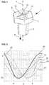
- Fig. 1shows schematically a screw 1 with a screw head 2 and a screw bolt 3.
- the screw bolt 3extends along a bolt axis 4, which is perpendicular to an upper side 6 and parallel to it, in the perspective view of FIG Fig. 1 underside of screw head 2 that does not appear.
- the design of a screw connectionis based on a force load on the screw 1 which runs exclusively along the bolt axis 4. In the present case, however, the screw is loaded in a direction of force 8 which runs obliquely to the bolt axis 4.
- an axial componente.g. B. the preload force, which is the main direction of force, there is also a transverse force.
- the main direction of forceruns perpendicular to a plane which, in turn, is perpendicular to the bolt axis 4.
- a stress distribution 10is created in the plane in the screw head 2, symbolized by contour lines of equal stress, which run asymmetrically to mutually perpendicular main axes 12, 14, which define an x / y coordinate system of the screw head 2 plane.
- the stress distribution 10would be completely symmetrical both to the x main axis 12 and to the y main axis 14.
- Fig. 2shows a section through the stress distribution 10, which is shown here in a plane which is perpendicular to the bolt axis and is positioned on the surface of the screw head.
- the stress in MPais plotted on the vertical axis and the lateral coordinate on the transverse axis.
- the zero value of the lateral coordinatecorresponds to the position of the bolt axis 4.
- the zero value of the tensioncorresponds to a tension-free state without bending of the top 6.
- Negative tension valuesindicate that the tension in the representation of the Fig. 1 acts downwards, that is to say acts on the screw head 2 in a deformation which results in a depression on the upper side 6.
- Fig. 2shows different curves that correspond to different stress states.
- the curvesrelate to the stress curve along the x main axis 12.
- the screw 1 under considerationis subjected to a pretensioning force along the bolt axis 4.
- Some curvesshow a state in which a transverse force directed parallel to the plane also acts on the underside of the bolt 3.
- Curves 24 and 22show the application of a force of 10% of the pretensioning force, curve 22 showing the x component and curve 24 showing the y component of the mechanical stress. Curves 23 and 24 show the application of a force of 10% of the pre-tensioning force in the positive y-direction.
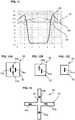
- a measuring device 25is provided for the screw 1, which is shown in FIG Fig. 3 in one embodiment in plan view of the screw head 2 and in Fig. 4 in a sectional view along the line AA of Fig. 3 is shown.
- the measuring device 25comprises a mounting plate 26, which is firmly attached to the top side 6 of the screw head 2, which serves as the mounting surface.
- the mounting plate 26has a strain measurement sensor 28 with at least two strain gauges, preferably four strain gauges arranged as a full bridge (as described above).
- the individual resistor (s)is / are electrically contacted via contact pads, which are not designated further. Details of the possible arrangements are based on the Fig. 12-13 still explained.
- Each strain measuring sensor 28is located on a web 30 which is delimited from the remaining material of the mounting plate 26 by incisions 32 or (not shown) severing cuts in such a way that the web is exposed on its long sides.
- the incisions 32 or severing cutsare summarized here under the term “longitudinal cuts”. They have the effect that a tension that acts transversely to the longitudinal extension of the web 30, which is referred to here as the longitudinal direction, puts the material of the mounting plate 26 under tension and, if necessary, deforms it, but not the web 30 transversely to its longitudinal extension.
- the longitudinal direction of the web and the plane in which the mounting surface is locateddetermine the three-dimensional direction of the web.
- Fig. 3shows two strain measuring sensors 28, 28 'on webs 30, 30' lying at right angles to one another. Accordingly, they also measure the elongation along longitudinal directions at right angles to one another. This biaxiality is optional.
- Each Si-DMSis a single resistor that has two piezoresistive coefficient axes along which the coefficient of the piezoresistive effect has a local maximum in magnitude; the Si-DMS have two coefficient axes that are at right angles to each other. They are commonly referred to as longitudinal and transverse axes, with the coefficient being positive in the longitudinal axis and negative in the transverse axis.
- the Si strain gaugesare arranged in such a way that one of the two coefficient axes lies along the longitudinal direction for each individual resistance.
- the cross-sensitivityusually present in strain gauges (ie the coefficient axis perpendicular to the longitudinal direction) no longer plays a role and does not lead to a signal.
- the three-dimensional direction of the (or each) web 30thus selects the direction along which the strain measuring sensor 28 measures the tension in the mounting plate 26 and, since this is firmly connected to the top 6 of the screw head 2, also in the screw head 2. It is no longer relevant whether the strain measuring sensor lies exactly on the bolt axis 4. Different voltage curves that, like Fig. 2 shows that the x-direction and y-direction could lead to the same voltage curve, are clearly separated. This also makes it easy to determine the direction vector of the operating force acting on the screw if at least two webs 30, 30 ', which do not extend in the same longitudinal direction, and strain sensors 28, 28' are used.
- strain measurement sensors 28it is also not necessary for the strain measurement sensors 28 to be arranged at points on the screw head 2 at which, due to the stress pattern, there is an anisotropy in the x or. y-direction would set.
- the filtering of the directionis achieved by the formation of the web 30; the three-dimensional direction of the web defines the direction filtered with regard to the stress measurement.
- An individual adjustment of the position of the strain measuring sensor on the screw head 2is no longer necessary. In this way, with a uniform and standardized measuring device 25, with different geometries, the operating force can be measured reliably in a precisely defined and easily selectable direction.
- the drastically reduced adjustment requirementalso allows the device 25 to be retrofitted on screw heads that have already been installed.
- Fig. 5which is also a sectional view similar to the Fig. 4 is.
- Fig. 6shows schematically a perspective view of the associated screw 1.
- recesses 36which can be created, for example, by embossing or milling the top 6 of the screw head 2, at least one free-standing web 30 is created on the top, on which the strain sensor 28 is then attached will. Alternatively, would Longitudinal slots in the top of the screw head form the web 30, which is then also free in the mechanical sense.
- FIG. 6shows two webs in a cross-shaped configuration, ie the web 30 is crossed by a further web 38, e.g. B. under 90 °.
- the crossed longitudinal directionsmake it possible to clearly select the x and y directions.
- a strain gaugecan be arranged on each web 30 on one side of the bolt axis 4, and another on the opposite side. The same applies to the web 38. This allows a bridge connection of the strain gauges, which is known to be extremely advantageous in terms of signaling.
- the cross-like design of the webs 30can also be achieved by a corresponding arrangement of the incisions 32 in a structure with a mounting plate 26.
- Fig. 7shows, already to design the mounting plate 26 in the shape of a cross and thus to provide the webs 30, 38 on which the strain measuring sensors 28 and 40 can then be arranged.
- a strain gaugeto each cross arm and to switch these four strain gauges as a full bridge. The arrangement is based on Fig. 13 explained in more detail.
- the use of a measuring device 25 with an independent mounting plate 26allows the measuring device to be completely preconfigured.
- the strain measuring sensor 28, its electrical supply and contacting as well as the signal transmission, which can be done by radio, for example,can already be prepared on the mounting plate 26.
- the mounting plate 26can be fastened by adhesive bonding or a soldering process, in particular using a metal solder 34 (cf. Fig. 4 ) take place. It is essential for the fastening that it transfers the stresses present in the screw head 2 to the mounting plate 26. The same applies in the event that the strain measuring sensor 28 is applied directly to a correspondingly designed top side 6 of the screw head 2. If the longitudinal cuts 32 are designed as severing cuts, it must be ensured that a metal solder does not completely fill the longitudinal cuts. This is easy to ensure by means of suitable soldering parameters and the width of the longitudinal cuts 32. If spring steel or a copper-containing metal compound is used for the mounting plate 26, the use of a metal solder is particularly simple. In general, soldering methods, glass frits or adhesives are possible for fastening the strain measuring sensor 28 on the web 30.
- the web height His chosen so that the desired anisotropy, i.e. insensitivity to transverse stresses, is achieved.
- a value of 100 ⁇ mis usually sufficient. Particularly preferred is a value from 100 to 500 ⁇ m, very particularly preferred is from 200 to 300 ⁇ m.
- the web height His automatically given by the thickness of the mounting plate 26.
- the height of the cross-shaped mounting plate 26is the web height H fixed.
- the lengthis preferably at least 2x, 5x, 10x or 20x the width and is more preferably not less than 1 cm.
- Fig. 8a disk-shaped element 41 on which the strain measuring sensor 28 is applied.
- the element 41has a mounting surface 42 on which a web 30 is formed by incisions 32.
- a strain measuring sensor 28is attached to the web 30.
- the web 30extends along a longitudinal direction 44, here referred to as the x-direction.
- the corresponding coordinate systemis in Fig. 8 entered and provides that the z-direction is perpendicular to a plane along which the web 30 extends.
- the y-directionis perpendicular to the longitudinal extension of the web 30, so that x and y span the plane of the mounting surface 42 in which the web 30 extends.
- Fig. 9shows a sectional view which clearly shows that the web 30 is formed by incisions 32 which extend along the x-direction.
- the orientation of the element 41 in Fig. 9corresponds to the Fig. 8 .
- FIG. 8shows a modification in that the web 30 is delimited by cuts that cut through a thin element 43. Whether incisions or cuts are used is freely selectable and can be determined depending on the application.
- Fig. 11shows the mechanical stresses detected by the Si strain measurement sensor 28, exemplarily in the unit MPa on the ordinate, compared to a position on the web 30.
- Curve 45shows the stress along the y-direction, which is given for an embodiment without incisions or cuts 32 would be.
- Curve 46shows the corresponding stresses in the x direction. As can be seen, the tensions are hardly distinguishable. This is due to the fact that conventional strain measuring sensors 28 are largely spatially isotropic with regard to the sensitivity to stresses.
- Curve 48shows the stress in the y direction for the
- Curve 50shows the stress in the x direction.
- the coefficient axes of the strain gauges in the strain measuring sensor 28all extend parallel or right-angled to the longitudinal direction 44 of the web 30.
- the stressescan be clearly distinguished, since when the strain measuring sensor 28 is positioned between the locations "2" and "4", those on the abscissa in Fig. 11 are plotted, the stress in the y-direction is significantly less than in the x-direction.
- the strain measuring sensor 28thus unambiguously measures the stress in the x-direction and has virtually no cross-sensitivity to stresses in the y-direction.
- the strain measuring sensor 28 fastened on the web 30measures only along a preferred direction, namely the direction 44, which is achieved by the longitudinal extension of the web exposure. In the Fig. 8- 11 this is purely for the sake of example the x-direction.
- a mounting surface 42as in Fig. 8 , 9 or 10 shown, can be provided universally. It is possible to provide them on an existing machine element or mechanical component. It is equally possible to subsequently attach a correspondingly configured component that provides the mounting surface 42 in order to measure mechanical stresses in the desired direction on an already installed component.
- the direction in which the mechanical stresses are measuredis defined by the longitudinal direction 44 of the web 30.
- the term "element"is to be understood only as an example. It can be any section in a component or a structure for which the operating force is to be measured that extends essentially (but not necessarily exclusively) along the z-direction.
- the mounting surface 42can be located inside a component that has a chamber that provides the mounting surface 42. The chamber can in particular be provided in a machine element that is loaded and for which the force is to be measured. A nut, washer, or screw would be examples.
- Figures 12A-12Bshow different configurations of the strain measurement sensor with different numbers or arrangements of strain gauges 54a-d.
- the strain measurement sensor 28is designed as a chip 52 on which Si strain gauges are formed.
- the web widthis twice the chip width; the web height is at least 0.2 times the chip width.
- the use of a chip 52is optional and the arrangements of the strain gauges 54a-d in FIGS Figures 12A-12B are also possible with individual strain gauges.
- the strain gauge sensor 28includes four strain gauges 54a-d.
- the large double arrows of the strain gauges 54a, cshow how their longitudinal axis lies.
- the thin arrows of the strain gauges 54b, dshow the direction of the transverse axis, and the cross lines illustrate that the longitudinal axes of the strain gauges 54b, d extend along the cross lines. Due to their inherent sensitivity, the strain gauges react along the transverse axis also on expansions, but with an inverted signal sign compared to expansions along the longitudinal axis.
- the strain gauges 54a-dare connected in a full bridge, as is known in the prior art. In this way, the signals advantageously add up both in the direction of the arrows drawn in and across it in the event of an expansion.
- the strain measurement sensor 28is therefore largely isotropically sensitive and generates a signal in the event of expansions along the longitudinal direction of the arrows and in the event of expansions that are exactly at right angles thereto.
- the strain measuring sensor 28is arranged on the web 30 in such a way that the coordinate axes of the strain gauges 54a-d are parallel to the longitudinal direction of the web 30. This is achieved in that the strain measurement sensor 28 is either arranged in such a way that the double arrows according to FIG Figure 12A extend parallel to the longitudinal direction or lie exactly at right angles to it.
- Figure 12Bshows a variant in which two strain gauges 54a, b are connected as a half bridge in the strain measurement sensor 28, which is again embodied as a chip 52 by way of example. This is simpler in terms of structure, but not as favorable in terms of signaling as the full bridge of the Figure 12A . Otherwise, this applies to the structure of the Figure 12A Said accordingly.
- Fig. 13shows the configuration with strain gauges 54a-d, which form a strain measurement sensor 28, on a cross-shaped web structure with a web 30 and a wide web 38 at right angles to it.
- the websintersect here; but this is not absolutely necessary.
- Analogous to the structure of the Figure 12Alie two strain gauges 54a, c with their longitudinal axes along the longitudinal direction of one web (here the web 30) and the other two strain gauges 54b, d with their transverse axes along the web direction of the other web (here the web 38).
- the four strain gauges 54a-dare in turn connected in a full bridge, so that an increased signal results, but without a resolution of the direction.
- the crosspieces with crossed longitudinal directionsmake it possible to measure in two orthogonal directions and thus to determine a force vector that has a component in the z-direction.
Landscapes
- Physics & Mathematics (AREA)
- General Physics & Mathematics (AREA)
- Force Measurement Appropriate To Specific Purposes (AREA)
- Measurement Of Force In General (AREA)
Description
Translated fromGermanDie Erfindung bezieht sich auf die Betriebskraftmessung bei einem mechanischen Bauelement, wobei ein Dehnungsmesssensor, der mindestens einen in einer Ebene angeordnete Dehnungsmessstreifen (DMS) mit einer Piezokoeffizientenachse umfasst, zum Einsatz kommt, um die Kraft senkrecht zur Ebene zu erfassen und auf einer Montagefläche ein entlang seiner Längsseiten freigestellter, länglicher Steg angeordnet ist, der sich parallel zu der Ebene erstreckt, und der Dehnungsmesssensor fest mit dem Steg verbunden ist.The invention relates to the operating force measurement in a mechanical component, a strain measuring sensor, which comprises at least one strain gauge (DMS) arranged in a plane and with a piezo coefficient axis, is used to detect the force perpendicular to the plane and along a mounting surface its longitudinal sides exposed, elongated web is arranged, which extends parallel to the plane, and the strain measurement sensor is firmly connected to the web.
Eine solche Betriebskraftmessung ist aus der
Mechanische Bauelemente werden häufig mit einer Kraft beaufschlagt, deren Hauptrichtung senkrecht zu einer Ebene steht, die aber insgesamt gegenüber der Ebene verkippt sein kann. Ein besonderes eingängiges Beispiel hierfür sind Maschinenelemente und hier insbesondere Schrauben. Der Belastungszustand einer Schraube ist durch die Vorspannkraft, mit der der Schraubenkopf auf die Unterlage drückt, und die betriebszustandsabhängige Betriebskraft charakterisiert. Die Hauptrichtung der sich in Summe ergebenden Kraft verläuft senkrecht zu einer Ebene, zu der die Schraubenbolzenachse senkrecht steht. Dies kann in einem sogenannten Verspannungsschaubild dargestellt werden. Das Schaubild berücksichtigt nur eine eindimensionale Belastung der Verbindung längs der Hauptrichtung. Zur Dimensionierung wird ebenfalls diese Art der Betrachtung herangezogen. Bei regelgerechter Belastung der Schraube, also bei Belastung ausschließlich entlang der Hauptrichtung, d.h. Längsrichtung des Schraubenbolzens, ist diese Dimensionierung auch sehr zuverlässig. Ein Versagen der Verbindung tritt oft dann auf, wenn die Schraube nicht mehr ausschließlich in der Hauptrichtung belastet wird und damit der aktuelle Betriebszustand von den Bedingungen abweicht, welche für die Auslegung maßgeblich waren. Eine Ursache für eine nicht-auslegungsgemäße Belastung ist oft Überlast oder der Verlust einiger Schrauben eines Verbundes.Mechanical components are often subjected to a force, the main direction of which is perpendicular to a plane, but which overall can be tilted with respect to the plane. A particularly catchy example of this are machine elements and, in this case, screws in particular. The load condition of a screw is characterized by the pretensioning force with which the screw head presses on the base and the operating force dependent on the operating condition. The main direction of the resulting force runs perpendicular to a plane to which the screw bolt axis is perpendicular. This can be shown in a so-called stress diagram. The diagram only takes into account a one-dimensional load on the connection along the main direction. This type of consideration is also used for dimensioning. With regular loading of the screw, that is to say with loading exclusively along the main direction, ie the longitudinal direction of the screw bolt, this dimensioning is also very reliable. A failure of the connection often occurs when the screw is no longer loaded exclusively in the main direction and the current operating state thus deviates from the conditions that were decisive for the design. One cause of a load that was not designed in accordance with the design is often overload or the loss of some screws in a connection.
Es stellt sich in diesem Fall die Problematik, eine Kraftmessung auszuführen, welche an einem mechanischen Bauelement mind. eine von der Hauptrichtung abweichende Kraftkomponente erfasst. Eine Schraube steht natürlich nur exemplarisch für ein mechanisches Bauelement, bei dem sich diese Frage stellt. Ein ganz anderes Gebiet wäre z.B. die Überwachung eines Bauwerkträgers.In this case, the problem arises of performing a force measurement which detects at least one force component deviating from the main direction on a mechanical component. Of course, a screw is only an example of a mechanical component in which this question arises. A completely different area would be, for example, the monitoring of a building girder.
Je nach Applikationsgebiet kann das mechanische Bauelement nur sehr schwer erreichbar sein. Ein Beispiel sind Maschinenelemente bei Windkraftrotoren, die ersichtlich nur mit erheblichem Aufwand zugänglich sind.Depending on the area of application, the mechanical component can be very difficult to reach. One example are machine elements in wind power rotors, which are obviously only accessible with considerable effort.
Die mind. eine von der Hauptrichtung abweichende Kraftkomponente erzeugt eine zweidimensionale Spannungsverteilung in der zur Hauptrichtung senkrechten Ebene. Es wurde deshalb überlegt, zur Messung einen Dehnungsmesssensor in einer ebenen Montagefläche anzuordnen, die parallel zur Ebene liegt. Durch die wirkende Kraft verformt sich die Montagefläche. Dies führt zu einem zweidimensionalen Spannungsfeld in der Montagefläche.The at least one force component deviating from the main direction creates a two-dimensional stress distribution in the plane perpendicular to the main direction. It was therefore considered to arrange a strain measuring sensor for the measurement in a flat mounting surface that is parallel to the plane. The mounting surface is deformed by the force acting. This leads to a two-dimensional field of tension in the mounting surface.
Bekannt für solche Dehnungsmesssensoren sind Silizium-DMS, die im Dehnungsmesssensor als Vollbrücke, Halbbrücke oder Viertelbrücke angeordnet sind. Sie sind kleiner und sensitiver als konventionelle Metall-Folien-DMS. Besonders vorteilhaft ist es, eine Vollbrücke aus vier in quadratischer Form liegende Si-Messwiderständen in einen Chip zu integrieren. Dieser Dehnungsmesssensor besitzt beispielweise eine Fläche von 0,25 mm2 und eine Dicke von 0,015 mm. Durch die Wirkung der piezoresistiven Konstanten für die Längsbelastung und die Querbelastung ergibt sich bei vier rechtwinklig zueinander angeordneten Messwiderständen eine Vollbrücke. In einem einachsigen Spannungszustand werden zwei Widerstände vergrößert und zwei vermindert. Zur Messung der Verformung der Oberfläche infolge der Vorspannkraft, bzw. der Betriebskraft, ist deshalb eine Position des Dehnungsmesssensors notwendig, an der in der Montagefläche eine möglichst große Differenz zwischen der mechanischen Spannung in x-und y-Richtung vorliegt. Der Dehnungsmesssensor muss damit dann ganz präzise auf der Montagefläche, z.B. einem Schraubenkopf, positioniert werden, da er in der Stelle der maximalen lateral anisotropen Verformung liegen muss. Ansonsten würden Querspannungen wirken, die das Signal verfälschen und unbrauchbar machen würden.Silicon strain gauges are known for such strain measurement sensors, which are arranged in the strain measurement sensor as a full bridge, half bridge or quarter bridge. They are smaller and more sensitive than conventional metal-foil strain gauges. It is particularly advantageous to integrate a full bridge made up of four square Si measuring resistors in a chip. This strain measuring sensor has, for example, an area of 0.25 mm2 and a thickness of 0.015 mm. The effect of the piezoresistive constants for the longitudinal load and the transverse load results in a full bridge with four measuring resistors arranged at right angles to one another. In a uniaxial stress state, two resistances are increased and two are decreased. To measure the deformation of the surface as a result of the pretensioning force or the operating force, a position of the strain measuring sensor is therefore necessary at which the greatest possible difference between the mechanical tension in the x and y directions is present in the mounting surface. The strain measuring sensor must then be positioned very precisely on the mounting surface, for example a screw head, since it must be in the point of maximum laterally anisotropic deformation. Otherwise transverse voltages would act, which would falsify the signal and make it unusable.
Die optimale Positionierung ist nur aufwendig, z.B. durch Simulationen, zu ermitteln. Sie hängt sowohl von der Richtung der zu messenden Kraftkomponente als auch von der Geometrie des mechanischen Bauelements ab. Diese Stelle liegt beim Beispielfall der Schraube in der Regel in einer Zone der Oberfläche, die über der Bolzenkante des Schraubenbolzens angeordnet ist. Die Positionierung ist deshalb hiervon der Schraubenkopfgröße abhängig. Je nach Abmessung und Ausgestaltung des mechanischen Bauelements, z.B. Maschinenelement, und der Richtung der zu messenden Kraftkomponente ist damit eine andere Position des Dehnungsmesssensors erforderlich. Die dadurch nötige hochpräzise Ausrichtung des Dehnungsmesssensors erhöht den Fertigungsaufwand beträchtlich und macht darüber hinaus eine Nachrüstung an bereits im Einsatz befindlichen mechanischen Bauelementen, z.B. Maschinenelementen wie Schrauben, unmöglich. Letzteres gilt auch für eine Kraftmessung durch Zwischenlegen eines Druckmesskörpers, wie es z.B. in der
Der Erfindung liegt deshalb die Aufgabe zugrunde, die Kraftmessung an einem mechanischen Bauelement, z.B. einem Maschinenelement wie einer Schraube, so auszugestalten, dass die Genauigkeit, mit der der Dehnungsmesssensor positioniert werden muss, reduziert ist und zugleich auch eine Nachrüstung an bereits im Einsatz befindlichen Elemente möglich wird. Dabei strebt man eine Lösung an, die möglichst universell verwendet werden kann.The invention is therefore based on the object of designing the force measurement on a mechanical component, e.g. a machine element such as a screw, in such a way that the accuracy with which the strain sensor must be positioned is reduced and at the same time also retrofitting on elements already in use becomes possible. The aim is to find a solution that can be used as universally as possible.
Die Erfindung ist in den unabhängigen Ansprüchen 1, 9 und 13 gekennzeichnet. Die abhängigen Ansprüche betreffen bevorzugte Weiterbildungen der Erfindung.The invention is characterized in
Die Erfindung stellt zum einen ein mechanisches Bauelement, z.B. ein Maschinenelement, bereit, das zur Messung einer Betriebskraft ausgebildet ist. An einer Montagefläche des mechanischen Bauelements ist ein längserstreckter und entlang seiner Längsseiten freigestellter Steg angeordnet. Der Steg hat somit eine durch die Längsseiten definierte Längsrichtung. Die Steghöhe beträgt optional mindestens 100 µm und die Stegbreite optional maximal 2 mm. Der Steg liegt in einer Ebene, die die Ebene des zweidimensionalen Spannungsfelds festlegt. I.d.R. erstreckt sich die Montagefläche auch längs dieser Ebene.The invention provides, on the one hand, a mechanical component, for example a machine element, which is designed to measure an operating force. On a mounting surface of the mechanical component, a longitudinally extending web that is exposed along its longitudinal sides is arranged. The web thus has a longitudinal direction defined by the longitudinal sides. The web height is optionally at least 100 µm and the web width is optionally a maximum of 2 mm. The web lies in a plane that defines the plane of the two-dimensional stress field. As a rule, the mounting surface also extends along this plane.
Auf dem Steg ist ein Dehnungsmesssensor befestigt, der mind. zwei brückenverschaltete Si-Dehnungsmesstreifen (DMS) umfasst. Die Befestigung kann durch Kleben oder Löten erfolgen; grundsätzlich sind stoffschlüssige Verbindungstechniken bevorzugt. Kraftschlüssige Verbindungstechnik ist optional möglich. Bei der Verwendung von zwei rechtwinklig zueinander angeordneten DMS liegt eine Halbbrücke und bei vierin quadratischer Form vorgesehenen DMS eine Vollbrücke vor. Jeder DMS hat zwei zueinander rechtwinklig liegende Koeffizientenachsen, auf der ein Koeffizient eines piezoresistiven Effekts ein lokales Betragsmaximum hat. Die Koeffizienten der beiden Achsen unterscheiden sich im Vorzeichen und u.U. im Betragsmaximum. Die Achse mit positivem Piezokoeffizienten wird gemeinhin als Längsachse bezeichnet, die andere als Querachse. Der Dehnungsmesssensors ist zum Steg so ausgerichtet, dass die Koeffizientenachse (bzw. eine der beiden Achsen) parallel zur der Längsrichtung des Stegs liegt. Eine Piezokoeffizientenachsen liegt eine parallel der Stegrichtung, die andere quer dazu. Bei der Halb- oder Vollbrücke liegt die eine Hälfte der DMS liegt mit ihrer Längsachse parallel zur Längsrichtung, die andere mit ihrer Querachse.A strain measurement sensor is attached to the bar, which comprises at least two bridge-connected Si strain gauges (DMS). The attachment can be done by gluing or soldering; In principle, cohesive connection techniques are preferred. Non-positive connection technology is optionally possible. When using two strain gauges arranged at right angles to one another, a half bridge is present, and when using four strain gages in a square shape, there is a full bridge. Every strain gage has two coefficient axes at right angles to each other, on which a coefficient of a piezoresistive effect has a local maximum. The coefficients of the two axes differ in the sign and possibly in the maximum amount. The axis with the positive piezo coefficient is commonly referred to as the longitudinal axis and the other as the transverse axis. The strain measurement sensor is aligned to the web in such a way that the coefficient axis (or one of the two axes) lies parallel to the longitudinal direction of the web. One piezo coefficient axis lies parallel to the web direction, the other at right angles to it. In the case of a half or full bridge, one half of the strain gauges lies with its longitudinal axis parallel to the longitudinal direction, the other half with its transverse axis.
Da der Steg seitlich freigestellt ist, also an seinen Längsseiten in Querrichtung zum Steg mit umgebendem Material nicht verbunden ist, erfasst der Dehnungsmesssensor nur Dehnungen längs der Steglängsrichtung. Die durch Orientierung der Längsrichtung und Lage der Ebene definierte dreidimensionale Ausrichtung des Steges filtert die Spannungsrichtung, welche vom Dehnungsmesssensor erfasst wird, der sich auf dem Steg befindet. Der Steg hat die Wirkung, dass er an der Montagefläche aus einer zweidimensionalen Spannungsverteilung eine Richtung extrahiert. Seine dreidimensionale Ausrichtung legt damit die Richtung der zu messenden Kraftkomponente fest. Verwendet man mehrere Stege, lässt sich die herausragende Funktion bekannter Messbrücken auch bei der Verwendung einzelner DMS beibehalten.Since the web is exposed laterally, that is to say is not connected to the surrounding material on its longitudinal sides in the transverse direction to the web, the strain measuring sensor only detects expansions along the longitudinal direction of the web. The three-dimensional alignment of the web, defined by the orientation of the longitudinal direction and the position of the plane, filters the stress direction, which is detected by the strain measuring sensor located on the web. The web has the effect of extracting a direction on the mounting surface from a two-dimensional stress distribution. Its three-dimensional alignment thus defines the direction of the force component to be measured. If you use several bars, the excellent function of known measuring bridges can be retained even when using individual strain gauges.
Die bei üblichen Si-basierten Dehnungsmesssensoren vorhandene Querempfindlichkeit (d.h. die andere Piezokoeffizientenachse) liegt quer zur Steglängsrichtung und führt deshalb zu keinem Signal in störendem Umfang. Auch in einem homogenen (isotropen) Spannungsfeld, d.h. bei gleicher mechanischer Spannung in Richtung x und y, erhält man so ein Messsignal, das sich nur auf die Spannung in Steglängsrichtung bezieht. Auf diese Weise ist die genaue Positionierung am mechanischen Bauelement unkritisch. Es muss nicht darauf geachtet werden, eine exakte Positionierung an einem Ort vorzunehmen, an dem keine Querspannungen auftreten; d. h. der Dehnungsmesssensor muss nicht mehr in einen Bereich gebracht werden, in dem eine Dehnung möglichst nur in einer Richtung und nicht quer dazu auftritt. Die Auswahl der Richtung, entlang der die Dehnung und damit die Verformung gemessen wird, wird ausschließlich durch die Ebene und Längsrichtung des Stegs festgelegt und ist damit positionierungsunabhängig. Die Ebene wird bevorzugt senkrecht zur Hauptrichtung der zu messenden Betriebskraft ausgerichtet.The cross-sensitivity present in conventional Si-based strain measurement sensors (i.e. the other piezo coefficient axis) lies transversely to the longitudinal direction of the web and therefore does not lead to a signal of a disruptive scope. Even in a homogeneous (isotropic) stress field, i.e. with the same mechanical stress in the x and y directions, a measurement signal is obtained that only relates to the stress in the longitudinal direction of the web. In this way, the exact positioning on the mechanical component is not critical. Care does not have to be taken to carry out an exact positioning in a place where no transverse stresses occur; d. H. the strain measuring sensor no longer has to be brought into an area in which strain occurs, if possible, only in one direction and not across it. The selection of the direction along which the elongation and thus the deformation is measured is determined exclusively by the plane and longitudinal direction of the web and is therefore independent of the position. The plane is preferably aligned perpendicular to the main direction of the operating force to be measured.
Wie der Steg freigestellt ist, ist nicht weiter relevant. Unter einem freigestellten Steg wird hier ein längserstrecktes, in der Regel quaderförmiges Materialvolumen verstanden, dessen Längskanten nicht mit benachbartem Material verbunden sind. Eine Steghöhe von 100 µm genügt für die Unterdrückung von Dehnungen quer zur Steglängsrichtung bereits. Besonders bevorzugt ist ein Dickenbereich von 100-500 µm, ganz besonders bevorzugt ein Dickenbereich von 200-300 µm. Die Steglänge liegt bevorzugt bei mind. 1 cm. Werte über 2 cm sind meist nicht erforderlich. Das Aspektverhältnis (Länge/Breite) liegt bevorzugt bei mind. 2 oder 5 oder 10 oder 20.How the bridge is exposed is no longer relevant. An exposed web is understood here to mean an elongated, generally cuboid-shaped material volume, the longitudinal edges of which are not connected to adjacent material. A web height of 100 µm is sufficient to suppress expansion across the web's longitudinal direction. A thickness range of 100-500 μm is particularly preferred, and a thickness range of 200-300 μm is very particularly preferred. The web length is preferably at least 1 cm. Values over 2 cm are usually not required. The aspect ratio (length / width) is preferably at least 2 or 5 or 10 or 20.
Der Steg kann als quaderförmiger Volumenbereich ausgebildet sein, der mit der Montagefläche, z.B. einer Oberseite des Maschinenelementes fest verbunden ist. Z.B. ist es möglich, den Steg am mechanischen Bauelement herauszuarbeiten, so dass er integral mit diesem verbunden ist. Hierzu kommen z.B. Längsschlitze in der Montagefläche, wobei die Tiefe der Längsschlitze die Steghöhe definiert, eine Prägung oder eine spanenden Bearbeitung in Frage. Gleichermaßen und besonders bevorzugt ist es möglich, eine Montageplatte einzusetzen, welche den Steg aufweist. Dies kann dadurch erfolgen, indem in die genannten Längsschlitze in Montageplatte eingebracht werden. Diese Schlitze können als Einschnitte in die Montageplatte hineinreichen. Natürlich ist es auch möglich, dass die Längsschlitze als Durchgangsschnitte in die Montageplatte eingebracht werden. Alternativ ist die Montageplatte bereits stegförmig. Der Dehnungsmesssensor wird mit der Montageplatte durch ein Fügeverfahren fest verbunden, beispielsweise unter Verwendung eines Lots. Die Montageplatte wird ihrerseits mit der Montagefläche fest verbunden.The web can be designed as a cuboid volume area which is firmly connected to the mounting surface, for example an upper side of the machine element. For example, it is possible to use the bridge to work out on the mechanical component so that it is integrally connected to it. For this purpose, for example, longitudinal slots in the mounting surface, where the depth of the longitudinal slots defines the web height, embossing or machining can be considered. It is equally and particularly preferably possible to use a mounting plate which has the web. This can be done by making the aforementioned longitudinal slots in the mounting plate. These slots can extend into the mounting plate as incisions. Of course, it is also possible for the longitudinal slots to be made in the mounting plate as through cuts. Alternatively, the mounting plate is already web-shaped. The strain measuring sensor is firmly connected to the mounting plate by a joining process, for example using a solder. The mounting plate is in turn firmly connected to the mounting surface.
Für die Montageplatte kommt als Material insbesondere Federstahl oder eine Kupferlegierung in Frage. Letztere erlaubt es besonders einfach, die Montageplatte mit der Montagefläche zu verlöten. Grundsätzlich kann die Montageplatte auch aufgeklebt werden.In particular, spring steel or a copper alloy come into consideration as the material for the mounting plate. The latter makes it particularly easy to solder the mounting plate to the mounting surface. In principle, the mounting plate can also be glued on.
Die Verwendung einer Montageplatte eröffnet einen weiteren Aspekt der Erfindung, nämlich eine Messvorrichtung vorzusehen, mit der bereits verbaute mechanische Bauelemente nachgerüstet werden oder Standardbauteile hinsichtlich einer Messung der Betriebskraft aufgerüstet werden. Die einzige Anforderung ist dabei lediglich, dass eine geeignete Montagefläche vorhanden ist, die sich längs der erwähnten Ebene erstreckt.t. Die exakte Lage des Montageortes spielt hingegen keine oder nur eine sehr untergeordnete Rolle, da anders als bei einer direkten Platzierung des Dehnungsmesssensors durch die richtungsfilternder Wirkung des Steges auf/in der Montageplatte eine sehr große Unempfindlichkeit hinsichtlich der Montageposition gegeben ist. Der Steg sorgt automatisch für die erforderliche x/y-Anisotropie, d. h. für die Messung der Dehnung ausschließlich entlang der Längsrichtung des Steges.The use of a mounting plate opens up a further aspect of the invention, namely to provide a measuring device with which mechanical components that have already been installed can be retrofitted or standard components are upgraded with regard to a measurement of the operating force. The only requirement is that there is a suitable mounting surface that extends along the plane mentioned. The exact location of the mounting location, on the other hand, plays no or only a very subordinate role, since, unlike with a direct placement of the strain gauge, the directional filtering effect of the web on / in the mounting plate is very insensitive to the mounting position. The web automatically ensures the required x / y anisotropy, i.e. H. for the measurement of the elongation exclusively along the longitudinal direction of the web.
Erfindungsgemäß ist weiter ein Verfahren zur Messung einer Betriebskraft bei einem mechanischen Bauelement vorgesehen. Analog zum erläuterten mechanische Bauelement und zur erläuterten Messvorrichtung, wird an einer Montagefläche des mechanische Bauelements ein längserstreckter und entlang seiner Längsseiten freigestellter Steg vorgesehen, der Stegabmessungen in den genannten Größenordnungen hat und auf dem der Dehnungsmesssensor kraftschlüssig in der bereits genannten Ausrichtung befestigt wird. Hinsichtlich der Verbindungstechnik gilt das zuvor gesagte. Mit einem derartigen Verfahren kann auch eine Messung an einem bereits verbauten mechanischen Bauelement durchgeführt werden. Es wird eine Montageplatte bereitgestellt, welche die genannten Eigenschaften und den genannten Dehnungsmesssensor hat. Die Montageplatte wird mit der Montagefläche verbunden, z.B. kraft- oder stoffschlüssig (gelötet oder geklebt).According to the invention, a method for measuring an operating force in a mechanical component is also provided. Analogous to the explained mechanical component and to the explained measuring device, a longitudinally extended web that is exposed along its long sides is provided on a mounting surface of the mechanical component, which has web dimensions in the stated orders of magnitude and on which the strain measurement sensor is non-positively attached in the orientation already mentioned. With regard to the connection technology, what has been said above applies. Such a method can also be used to carry out a measurement on a mechanical component that has already been installed. A mounting plate is provided which has the properties mentioned and the strain measurement sensor mentioned. The mounting plate is connected to the mounting surface, for example with a force fit or material fit (soldered or glued).
Das Verfahren und das mechanische Bauelement sowie die Messvorrichtung erlauben es, die Betriebskraft aktuell zu messen. So kann z.B. eine Vorspannkraft erfasst werden. Auf diese Weise lässt sich eine Fehlbelastung oder gar Versagen eines mechanischen Bauelements, z.B. ein Losrütteln einer Schraube frühzeitig erkennen.The method and the mechanical component as well as the measuring device make it possible to measure the operating force currently. For example, a pre-tensioning force can be recorded. In this way, incorrect loading or even failure of a mechanical component, e.g. a screw shaking loose, can be detected at an early stage.
Für eine mehrdimensionale Krafterfassung ist es vorgesehen, mindestens zwei Dehnungsmessstreifen auf Stegen vorzusehen, die in einem Winkel zueinander liegen, bevorzugt im 90°--Winkel.For a multi-dimensional force measurement, provision is made for at least two strain gauges to be provided on webs that are at an angle to one another, preferably at a 90 ° angle.
Das erfindungsgemäße Konzept hat den Vorteil, dass kein Eingriff in den Kraftfluss eines mechanischen Bauelements genommen werden muss. Genaue Kenntnis über den Kraft- oder Spannungsverlauf ist nicht mehr nötig, um eine Betriebskraft in bestimmter Richtung zu messen. Die verwendeten Befestigungsmethoden können langzeitstabile Fügeverfahren, wie Glasfritten oder Metalllote einsetzen. Die Montage ist einfach und die Ausführung robust. Ganz besonders bevorzugt ist es, dass ein einziger Sensor für verschiedenste mechanische Bauelemente verwendet werden kann. Das mechanische Bauelement, z.B. eine Schraubenverbindung kann lebenslang überwacht werden.The inventive concept has the advantage that there is no need to intervene in the force flow of a mechanical component. Exact knowledge of the force or voltage curve is no longer necessary in order to measure an operating force in a certain direction. The fastening methods used can use long-term stable joining processes, such as glass frits or metal solders. Installation is simple and the design is robust. It is very particularly preferred that a single sensor can be used for a wide variety of mechanical components. The mechanical component, e.g. a screw connection, can be monitored for life.
Es versteht sich, dass die vorstehend genannten und die nachstehend noch zu erläuternden Merkmale nicht nur in den angegebenen Kombinationen, sondern auch in anderen Kombinationen oder in Alleinstellung einsetzbar sind, ohne den Rahmen der vorliegenden Erfindung zu verlassen.It goes without saying that the features mentioned above and those yet to be explained below can be used not only in the specified combinations, but also in other combinations or on their own, without departing from the scope of the present invention.
Nachfolgend wird die Erfindung anhand von Ausführungsbeispielen unter Bezugnahme auf die beigefügten Zeichnungen, die ebenfalls erfindungswesentliche Merkmale offenbaren, noch näher erläutert. Diese Ausführungsbeispiele dienen lediglich der Veranschaulichung und sind nicht als einschränkend auszulegen. Sie beziehen sich rein exemplarisch auf eine Schraube als mechanisches Bauelement. Weiter ist eine Beschreibung eines Ausführungsbeispiels mit einer Vielzahl von Elementen oder Komponenten nicht dahingehend auszulegen, dass alle diese Elemente oder Komponenten zur Implementierung notwendig sind. Vielmehr können andere Ausführungsbeispiele auch alternative Elemente und Komponenten, weniger Elemente oder Komponenten oder zusätzliche Elemente oder Komponenten enthalten. Elemente oder Komponenten verschiedener Ausführungsbespiele können miteinander kombiniert werden, sofern nichts anderes angegeben ist. Modifikationen und Abwandlungen, welche für eines der Ausführungsbeispiele beschrieben werden, können auch auf andere Ausführungsbeispiele anwendbar sein. Zur Vermeidung von Wiederholungen werden gleiche oder einander entsprechende Elemente in verschiedenen Figuren mit gleichen Bezugszeichen bezeichnet und nicht mehrmals erläutert. Von den Figuren zeigen:
- Fig. 1
- eine Schemadarstellung einer Schraube mit einem Schraubenkopf zur Erläuterung eines nicht-axialen Belastungszustandes der Schraube,
- Fig. 2
- eine Erläuterung der Spannungsverhältnisse beim Betrieb der Schraube der
Fig. 1 in einer Schraubenverbindung mit wechselnder Richtung der belastenden Kraft, - Fig. 3
- eine schematische Draufsicht auf den Schraubenkopf mit einer Messvorrichtung zum Messen der Spannungsverhältnisse in der Schraube,
- Fig. 4
- eine Schnittdarstellung entlang der Linie A-A der
Fig. 3 , - Fig. 5
- eine Schnittdarstellung ähnlich der
Fig. 4 für eine alternative Ausführungsform der Spannungsmessung, bei der Teile der Messvorrichtung durch den Schraubenkopf ausgebildet sind, - Fig. 6 eine
- schematische Perspektivdarstellung einer Schraube gemäß der Ausführungsform der
Fig. 5 , - Fig. 7 eine
- Perspektivdarstellung einer Schraube mit einer gegenüber den
Fig. 3 und 4 abgewandelten Messvorrichtung, - Fig. 8 eine
- Schemadarstellung eines Elementes zur Messung der Spannungsverhältnisse, die sich durch eine Kraft ergeben, welche längs einer z-Achse wirkt, die in
Fig. 8 eingetragen ist, - Fig. 9
- eine Schnittdarstellung des Elementes der
Fig. 8 , - Fig. 10
- eine Schnittdarstellung ähnlich der
Fig. 9 für ein abgewandeltes Element, - Fig. 11
- mechanische Spannungen im Element der
Fig. 8 ,9 oder 10 verglichen mit mechanischen Spannungen eines Elementes, - Fig. 12A-12C
- verschiedene Ausgestaltungen eines Chips als Dehnungsmesssensor mit Dehnungsmesstreifen in Vollbrücke (
Fig. 12A ), Halbbrücke (Fig. 12B ) und Viertelbrücke (Fig. 12C ) und - Fig. 13
- eine kreuzförmige Anordnung aus zwei Stegen mit vier Dehnungsmessstreifen in Vollbrückenverschaltung.
- Fig. 1
- a schematic representation of a screw with a screw head to explain a non-axial load condition of the screw,
- Fig. 2
- an explanation of the tension conditions during the operation of the screw of the
Fig. 1 in a screw connection with alternating direction of the loading force, - Fig. 3
- a schematic top view of the screw head with a measuring device for measuring the stress conditions in the screw,
- Fig. 4
- a sectional view along the line AA of
Fig. 3 , - Fig. 5
- a sectional view similar to that
Fig. 4 for an alternative embodiment of the voltage measurement, in which parts of the measuring device are formed by the screw head, - Fig. 6 a
- schematic perspective illustration of a screw according to the embodiment of FIG
Fig. 5 , - Fig. 7 a
- Perspective view of a screw with one opposite the
Figs. 3 and 4 modified measuring device, - Fig. 8 a
- Schematic representation of an element for measuring the stress ratios that result from a force that acts along a z-axis that appears in
Fig. 8 is registered, - Fig. 9
- a sectional view of the element of
Fig. 8 , - Fig. 10
- a sectional view similar to that
Fig. 9 for a modified element, - Fig. 11
- mechanical stresses in the element of
Fig. 8 ,9 or 10 compared to the mechanical stresses of an element, - Figures 12A-12C
- various designs of a chip as a strain measurement sensor with strain gauges in a full bridge (
Figure 12A ), Half bridge (Figure 12B ) and quarter bridge (Figure 12C ) and - Fig. 13
- a cross-shaped arrangement of two bars with four strain gauges in full bridge connection.
Keine Querkraft liegt in den Kurven 16 und 18 vor, welche die Komponenten der mechanischen Spannung in Richtung x und y (Sigma(x), Sigma(y)) zeigen. Wie zu sehen ist, ist der Spannungsverlauf völlig symmetrisch zur Bolzenachse 4, die dem Nullwert auf der Querachse entspricht.There is no transverse force in
Die Kurven 24 und 22 zeigen das Angreifen einer Kraft von 10% der Vorspannkraft, wobei die Kurve 22 die x-Komponente und die Kurve 24 die y-Komponente der mechanischen Spannung zeigen. Die Kurven 23 und 24 zeigen das Angreifen einer Kraft von 10% der Vorspannkraft hin zur positiven y-Richtung.
Um diese Spannungszustände messen zu können, ist für die Schraube 1 eine Messvorrichtung 25 vorgesehen, die in
In dieser Ausführungsform umfasst die Messvorrichtung 25 eine Montageplatte 26, welche auf die als Montagefläche dienende Oberseite 6 des Schraubenkopfs 2 fest aufgebracht ist. Die Montageplatte 26 hat einen Dehnungsmesssensor 28, mit mind. zwei DMS, bevorzugt vier als Vollbrücke angeordneten DMS (wie oben beschrieben). Der Einzelwiderstand/die Einzelwiderstände ist/sind über nicht weiter bezeichnete Kontaktpads elektrisch kontaktiert. Details der möglichen Anordnungen werden anhand der
Jeder Dehnungsmesssensor 28 befindet sich auf einem Steg 30, der durch Einschnitte 32 oder (nicht gezeigte) Durchtrennungsschnitte vom restlichen Material der Montageplatte 26 so abgegrenzt wird, dass der Steg an seinen Längsseiten freigestellt ist. Die Einschnitte 32 oder Durchtrennungsschnitte werden hier unter dem Begriff "Längsschnitte" zusammengefasst. Sie haben die Wirkung, dass eine Spannung, die quer zur Längserstreckung des Steges 30, die hier als Längsrichtung bezeichnet wird, wirkt, zwar das Material der Montageplatte 26 unter Spannung setzt und ggf. verformt, nicht jedoch den Steg 30 quer zur seiner Längserstreckung. Die Längsrichtung des Steges und die Ebene, in der die Montagefläche liegt, legen die dreidimensionale Richtung des Steges fest. Sie definieren damit zugleich eine Filterrichtung, denn nur in dieser dreidimensionale Richtung misst der auf dem Steg fest montierte Dehnungsmesssensor 28 Spannungen.
Jeder Si-DMS ist ein Einzelwiderstand, der zwei piezoresistive Koeffizientenachsen aufweist, entlang der der Koeffizient des piezoresistiven Effekts im Betrag ein lokales Maximum hat; die Si-DMS haben zwei zueinander rechtwinklig liegende Koeffizientenachsen. Sie werden üblicherweise als Längs- und Querachsen bezeichnet, wobei der Koeffizient in Längsachse positiv, in Querachse negativ ist. In der Halb- oder Viertelbrücke sind die Si-DMS so angeordnet, dass für jeden Einzelwiderstand eine der zwei Koeffizientenachsen entlang der Längsrichtung liegt. Die bei Dehnungsmessstreifen i.d.R. vorhandene Querempfindlichkeit (d.h. die senkrecht zur Längsrichtung liegende Koeffizientenachse) spielt keine Rolle mehr und führt nicht zu einem Signal.Each Si-DMS is a single resistor that has two piezoresistive coefficient axes along which the coefficient of the piezoresistive effect has a local maximum in magnitude; the Si-DMS have two coefficient axes that are at right angles to each other. They are commonly referred to as longitudinal and transverse axes, with the coefficient being positive in the longitudinal axis and negative in the transverse axis. In the half or quarter bridge, the Si strain gauges are arranged in such a way that one of the two coefficient axes lies along the longitudinal direction for each individual resistance. The cross-sensitivity usually present in strain gauges (ie the coefficient axis perpendicular to the longitudinal direction) no longer plays a role and does not lead to a signal.
Die dreidimensionale Richtung des (bzw. jedes) Steges 30 selektiert damit die Richtung, entlang der der Dehnungsmesssensor 28 die Spannung in der Montageplatte 26 und, da diese fest mit der Oberseite 6 des Schraubenkopfes 2 verbunden ist, auch im Schraubenkopf 2 misst. Es ist nicht mehr relevant, ob der Dehnungsmesssensor exakt auf der Bolzenachse 4 liegt. Unterschiedliche Spannungsverläufe, die, wie
Auch ist es nicht erforderlich, dass die Dehnungsmesssensoren 28 an Stellen auf dem Schraubenkopf 2 angeordnet sind, an denen sich aufgrund des Spannungsbildes eine Anisotropie in x-bzw. y-Richtung einstellen würde. Die Filterung der Richtung wird durch die Ausbildung des Steges 30 erreicht; die dreidimensionale Richtung des Steges legt die hinsichtlich der Spannungsmessung gefilterte Richtung fest. Eine individuelle Anpassung der Lage der Dehnungsmesssensor auf den Schraubenkopf 2 ist nicht mehr erforderlich. Auf diese Weise kann mit einer einheitlichen und standardisierten Messvorrichtung 25 bei unterschiedlichen Geometrien zuverlässig die Betriebskraft in einer genau festgelegten und einfach zu wählenden Richtung gemessen werden. Auch erlaubt die drastisch reduzierte Justieranforderung es, die Vorrichtung 25 an Schraubenköpfen nachzurüsten, die bereits verbaut sind.It is also not necessary for the
Wesentlich für die Wirkung der Ausführungsform der
Natürlich kann die kreuzartige Ausbildung der Stege 30 auch durch entsprechende Anordnung der Einschnitte 32 in einem Aufbau mit Montageplatte 26 erreicht werden. Gleichermaßen ist es möglich, wie
Die Verwendung einer Messvorrichtung 25 mit eigenständiger Montageplatte 26 erlaubt es, die Messvorrichtung bereits vollständig vorzukonfigurieren. D. h. den Dehnungsmesssensor 28, seine elektrische Versorgung und Kontaktierung sowie auch die Signalübertragung, die beispielsweise per Funk erfolgen kann, können auf der Montageplatte 26 bereits vorbereitet werden.The use of a measuring
Die Befestigung der Montageplatte 26 kann durch eine Klebung oder ein Lötverfahren, insbesondere unter Verwendung eines Metalllots 34 (vgl.
Die Steghöhe H ist so gewählt, dass die gewünscht Anisotropie, also Unempfindlichkeit auf Querspannungen erreicht ist. Ein Wert von 100 µm genügt in der Regel. Besonders bevorzugt ist ein Wert von 100 bis 500 µm, ganz besonders bevorzugt ist von 200 bis 300 µm. Im Fall eines Durchtrennungsschnitts ist die Steghöhe H automatisch durch die Dicke der Montageplatte 26 gegeben. Gleiches gilt für die Bauweise der
Zur Verdeutlichung des Prinzips, mit dem die Ausführungsformen Kräfte messen, zeigt
Ausführungsform der
Die Verwendung des freigestellten, länglichen Stegs 30, beispielsweise durch Einschnitte oder Durchschnitte 32, erlaubt somit die an und für sich Dehnungsmesssensor innewohnende Isotropie aufzuheben und eine klare Vorzugsrichtung für die Messung zu erzielen. Der auf dem Steg 30 befestigte Dehnungsmesssensor 28 misst nur entlang einer Vorzugsrichtung, nämlich der Richtung 44, welche durch die Längserstreckung der Stegfreistellung erreicht ist. In den
Eine Montagefläche 42, wie in
Die Stege mit gekreuzten Längsrichtungen erlauben es in zwei orthogonalen Richtungen zu messen und so einen Kraftvektor zu ermitteln, der eine Komponente in z-Richtung hat.The crosspieces with crossed longitudinal directions make it possible to measure in two orthogonal directions and thus to determine a force vector that has a component in the z-direction.
Claims (15)
- Mechanical component, in particular machine element (2), on which at least two longitudinally extending strain measuring sensors (28, 40) are attached for measuring an operating force on a mounting surface (6, 42) and on the mounting surface (6, 42) there is arranged at least one elongated web (30), which is detached along its longitudinal sides and extends parallel to a plane in which the mounting surface (6, 42) lies,
characterized in that- the at least two strain measuring sensors (28, 40) are connected to form a bridge and respectively take the form of an Si strain gauge (54a-d), which has a first piezoelectric coefficient axis and, substantially perpendicular thereto, a second piezoelectric coefficient axis,- a number of elongated webs (30, 38), which extend in different longitudinal directions, are arranged on the mounting surface (6), one of the strain measuring sensors (28, 40) being securely connected to each web (30, 38), and- each of the strain measuring sensors (28, 40) is aligned with the respective web (30, 38), to which it is connected, such that-- for one of the strain measuring sensors (28), the first piezoelectric coefficient axis runs along the longitudinal sides of the respective web (30) and the second piezoelectric coefficient axis runs transversely thereto and-- for the other of the strain measuring sensors (40), the second piezoelectric coefficient axis runs along the longitudinal sides of the respective web (38) and the first piezoelectric coefficient axis runs transversely thereto. - Mechanical component according to Claim 1,characterized in that four strain gauges (54a-d), connected to form a full bridge, are provided, the first piezoelectric coefficient axis is a longitudinal piezoelectric coefficient axis and the second piezoelectric coefficient axis is a transverse piezoelectric coefficient axis, andin that two of the strain gauges (54a-d) lie with their longitudinal piezoelectric coefficient axis parallel to the longitudinal sides of the respective web (30, 38) and the other two of the Si strain gauges (54a-d) lie with their transverse piezoelectric coefficient axis parallel to the longitudinal sides of the respective web (30, 38).
- Mechanical component according to Claim 1 or 2,characterized in that a mounting plate (4), which forms or has the webs (30, 38), is attached on the mounting surface (6).
- Mechanical component according to Claim 3,characterized in that the strain measuring sensors (28, 40) are soldered to the mounting plate (4) and the mounting plate (4) is adhesively attached or soldered to the upper side (6) of a screw head (2).
- Mechanical component according to either of Claims 3 and 4,characterized in that the mounting plate (4) comprises a material which is adapted to the material of the mounting surface with regard to the mechanical elasticity and strength properties, in particular is spring steel, a copper alloy or ceramic.
- Mechanical component according to one of the above claims,characterized in that the webs (30, 38) are respectively formed by incisions (8) or longitudinal slits that are incorporated in the mounting surface (6, 42) or the mounting plate (4), orin that the webs (30, 38) are respectively formed as an integral projection, which projects from the mounting surface (6).
- Mechanical component according to one of the above claims,characterized in that the webs (30, 38) cross one another.
- Mechanical component according to Claim 7,characterized in that three webs (30), the different longitudinal directions of which lie at an angle of 100-140 degrees to one another, are arranged orin that two webs (30), the different longitudinal directions of which lie at an angle of 80-100 degrees to one another, are arranged on a screw head (2).
- Measuring device for measuring an operating force in the case of a mechanical component, for example a machine element, the measuring device having at least two longitudinally extending strain measuring sensors (28, 40) and at least one elongated web (30, 38), which is detached along its longitudinal sides,
characterized in that- the at least two strain measuring sensors (28, 40) are connected to form a bridge and respectively take the form of an Si strain gauge (54a-d), which has a first piezoelectric coefficient axis and, substantially perpendicular thereto, a second piezoelectric coefficient axis,- the measuring device also has a mounting plate (4), which is designed for secure connection to a mounting surface (6) of the mechanical component (2) and which has a number of elongated webs (30, 38), which extend in different longitudinal directions along the mounting plate (4) and are respectively formed as detached along their longitudinal sides, one of the strain measuring sensors (28, 40) being securely connected to each web (30, 38), and- each of the strain measuring sensors (30, 38) being aligned with the respective web (30, 38), to which it is connected, such that-- for one of the strain measuring sensors (28), the first piezoelectric coefficient axis runs along the longitudinal sides of the web (30) and the second piezoelectric coefficient axis runs transversely thereto and-- for the other of the strain measuring sensors (40), the second piezoelectric coefficient axis runs along the longitudinal sides of the respective web (38) and the first piezoelectric coefficient axis runs transversely thereto. - Measuring device according to Claim 9,characterized in that four strain gauges (54a-d), connected to form a full bridge, are provided, the first piezoelectric coefficient axis is a longitudinal piezoelectric coefficient axis and the second piezoelectric coefficient axis is a transverse piezoelectric coefficient axis, andin that two of the strain gauges (54a-d) lie with their longitudinal piezoelectric coefficient axis parallel to the longitudinal sides of the respective web (30, 38) and the other two of the Si strain gauges (54a-d) lie with their transverse piezoelectric coefficient axis parallel to the longitudinal sides of the respective web (30, 38).
- Measuring device according to Claim 9 or 10,characterized in that the mounting plate (4) is formed for adhesively attaching or soldering onto the mounting surface (6), the mounting plate (4) optionally comprising spring steel or a copper alloy as the material.
- Measuring device according to one of Claims 9 to 11,characterized in that the webs (30, 38) cross one another.
- Method for measuring an operating force in the case of a mechanical component, for example a machine element, at least two longitudinally extending strain measuring sensors (28, 40) being used and at least one elongated web (30), which is detached along its longitudinal sides and extends on the or parallel to a plane in which the mounting surface (6, 42) lies, being provided on a mounting surface (6, 42) of the mechanical component (2),characterized in that- the at least two strain measuring sensors (28, 40) are connected to form a bridge and respectively take the form of an Si strain gauge (54a-d), which has a first piezoelectric coefficient axis and, substantially perpendicular thereto, a second piezoelectric coefficient axis,- a number of elongated webs (30, 38), which extend in different longitudinal directions, are arranged on the mounting surface (6), one of the strain measuring sensors (28, 40) being securely connected to each web (30, 38), and- each of the strain measuring sensors (30, 38) is aligned with the respective web (30, 38), to which it is connected, such that-- for one of the strain measuring sensors (28), the first piezoelectric coefficient axis runs along the longitudinal sides of the respective web (30) and the second piezoelectric coefficient axis runs transversely thereto and-- for the other of the strain measuring sensors (40), the second piezoelectric coefficient axis runs along the longitudinal sides of the respective web (38) and the first piezoelectric coefficient axis runs transversely thereto.
- Method according to Claim 13,characterized in that a mounting plate (4), which has the webs (30, 38), preferably as a result of longitudinal slits (32) incorporated in the mounting plate (4), is provided for measuring on an already installed mechanical component (2), and the mounting plate (4) with strain measuring sensors (28, 40) fastened on the webs (30) is securely connected to the mechanical component (2).
- Method according to Claim 13 or 14,characterized in that the direction of the operating force is determined.
Priority Applications (1)
| Application Number | Priority Date | Filing Date | Title |
|---|---|---|---|
| EP18205415.5AEP3650825B1 (en) | 2018-11-09 | 2018-11-09 | Operational force measurement of a mechanical component |
Applications Claiming Priority (1)
| Application Number | Priority Date | Filing Date | Title |
|---|---|---|---|
| EP18205415.5AEP3650825B1 (en) | 2018-11-09 | 2018-11-09 | Operational force measurement of a mechanical component |
Publications (2)
| Publication Number | Publication Date |
|---|---|
| EP3650825A1 EP3650825A1 (en) | 2020-05-13 |
| EP3650825B1true EP3650825B1 (en) | 2021-11-03 |
Family
ID=64270711
Family Applications (1)
| Application Number | Title | Priority Date | Filing Date |
|---|---|---|---|
| EP18205415.5AActiveEP3650825B1 (en) | 2018-11-09 | 2018-11-09 | Operational force measurement of a mechanical component |
Country Status (1)
| Country | Link |
|---|---|
| EP (1) | EP3650825B1 (en) |
Citations (1)
| Publication number | Priority date | Publication date | Assignee | Title |
|---|---|---|---|---|
| US4079624A (en)* | 1976-12-29 | 1978-03-21 | Kulite Semiconductor Products, Inc. | Load washer transducer assembly |
Family Cites Families (3)
| Publication number | Priority date | Publication date | Assignee | Title |
|---|---|---|---|---|
| FR2696215B1 (en) | 1992-09-25 | 1994-12-02 | Serge Bras | Assembly element and assembly method and machine. |
| DE19842231C1 (en)* | 1998-09-15 | 2000-07-06 | Test Gmbh | Measuring device for determining the total tightening torque, the head friction torque and the preload force of a tightened screw connection |
| DE10217283B4 (en) | 2002-04-12 | 2005-10-13 | Fraunhofer-Gesellschaft zur Förderung der angewandten Forschung e.V. | Device for setting and checking the clamping force of screwed connections |
- 2018
- 2018-11-09EPEP18205415.5Apatent/EP3650825B1/enactiveActive
Patent Citations (1)
| Publication number | Priority date | Publication date | Assignee | Title |
|---|---|---|---|---|
| US4079624A (en)* | 1976-12-29 | 1978-03-21 | Kulite Semiconductor Products, Inc. | Load washer transducer assembly |
Also Published As
| Publication number | Publication date |
|---|---|
| EP3650825A1 (en) | 2020-05-13 |
Similar Documents
| Publication | Publication Date | Title |
|---|---|---|
| EP2549253B1 (en) | Measuring body, force sensor and measuring assembly for measuring forces | |
| AT503816A4 (en) | PIEZOELECTRIC SENSOR | |
| WO2011039566A1 (en) | Measuring device allowing detection of deformations | |
| WO2004070334A1 (en) | Measuring sensor comprising a pre-stressing device | |
| CH682108A5 (en) | ||
| EP3894814A1 (en) | Arrangement for determining the deflection of a component, and method for producing such an arrangement | |
| EP0459947A2 (en) | Bar tension measuring system in for example injection moulding machines | |
| DE10217284B4 (en) | Device for controlling screw connections | |
| DE10154231A1 (en) | Seat occupant sensing unit for automobile, has strain gauge, accommodated between bearing area and main section, which senses elastic deformation of arm due to presence of occupant in vehicle seat | |
| DE3834089A1 (en) | FORCE SENSOR | |
| DE10221219B4 (en) | pressure sensor | |
| EP2554964B1 (en) | Pressure and temperature measuring device | |
| EP3650825B1 (en) | Operational force measurement of a mechanical component | |
| DE3438498C2 (en) | ||
| DE102005034765A1 (en) | Device for measuring a torque in a torque tool and torque tool for detecting an applied torque | |
| WO2006136182A1 (en) | Pressure sensor | |
| EP0483912B1 (en) | Disk-shaped shear force sensor for a load cell | |
| DE102010012701B4 (en) | Micro-force sensor | |
| DE102004033925B4 (en) | Torque transducer | |
| DE102011106392A1 (en) | Device for measuring force on a measuring body | |
| DE10127230A1 (en) | Pressure sensing device | |
| DE8915981U1 (en) | Plate-shaped sensor element and pressure, force or acceleration sensor equipped with it | |
| DE102020129183A1 (en) | Pressure measuring device and method for manufacturing a pressure measuring device | |
| DE102011105539B4 (en) | Device for converting a force into an electrical signal, in particular piezoresistive force sensor | |
| AT523510B1 (en) | Structured, piezoelectric sensor element |
Legal Events
| Date | Code | Title | Description |
|---|---|---|---|
| PUAI | Public reference made under article 153(3) epc to a published international application that has entered the european phase | Free format text:ORIGINAL CODE: 0009012 | |
| STAA | Information on the status of an ep patent application or granted ep patent | Free format text:STATUS: THE APPLICATION HAS BEEN PUBLISHED | |
| AK | Designated contracting states | Kind code of ref document:A1 Designated state(s):AL AT BE BG CH CY CZ DE DK EE ES FI FR GB GR HR HU IE IS IT LI LT LU LV MC MK MT NL NO PL PT RO RS SE SI SK SM TR | |
| AX | Request for extension of the european patent | Extension state:BA ME | |
| STAA | Information on the status of an ep patent application or granted ep patent | Free format text:STATUS: REQUEST FOR EXAMINATION WAS MADE | |
| 17P | Request for examination filed | Effective date:20201113 | |
| RBV | Designated contracting states (corrected) | Designated state(s):AL AT BE BG CH CY CZ DE DK EE ES FI FR GB GR HR HU IE IS IT LI LT LU LV MC MK MT NL NO PL PT RO RS SE SI SK SM TR | |
| GRAP | Despatch of communication of intention to grant a patent | Free format text:ORIGINAL CODE: EPIDOSNIGR1 | |
| STAA | Information on the status of an ep patent application or granted ep patent | Free format text:STATUS: GRANT OF PATENT IS INTENDED | |
| INTG | Intention to grant announced | Effective date:20210525 | |
| GRAS | Grant fee paid | Free format text:ORIGINAL CODE: EPIDOSNIGR3 | |
| GRAA | (expected) grant | Free format text:ORIGINAL CODE: 0009210 | |
| STAA | Information on the status of an ep patent application or granted ep patent | Free format text:STATUS: THE PATENT HAS BEEN GRANTED | |
| AK | Designated contracting states | Kind code of ref document:B1 Designated state(s):AL AT BE BG CH CY CZ DE DK EE ES FI FR GB GR HR HU IE IS IT LI LT LU LV MC MK MT NL NO PL PT RO RS SE SI SK SM TR | |
| REG | Reference to a national code | Ref country code:GB Ref legal event code:FG4D Free format text:NOT ENGLISH | |
| REG | Reference to a national code | Ref country code:AT Ref legal event code:REF Ref document number:1444370 Country of ref document:AT Kind code of ref document:T Effective date:20211115 Ref country code:CH Ref legal event code:EP | |
| REG | Reference to a national code | Ref country code:DE Ref legal event code:R096 Ref document number:502018007667 Country of ref document:DE | |
| REG | Reference to a national code | Ref country code:IE Ref legal event code:FG4D Free format text:LANGUAGE OF EP DOCUMENT: GERMAN | |
| REG | Reference to a national code | Ref country code:LT Ref legal event code:MG9D | |
| REG | Reference to a national code | Ref country code:NL Ref legal event code:MP Effective date:20211103 | |
| PG25 | Lapsed in a contracting state [announced via postgrant information from national office to epo] | Ref country code:RS Free format text:LAPSE BECAUSE OF FAILURE TO SUBMIT A TRANSLATION OF THE DESCRIPTION OR TO PAY THE FEE WITHIN THE PRESCRIBED TIME-LIMIT Effective date:20211103 Ref country code:LT Free format text:LAPSE BECAUSE OF FAILURE TO SUBMIT A TRANSLATION OF THE DESCRIPTION OR TO PAY THE FEE WITHIN THE PRESCRIBED TIME-LIMIT Effective date:20211103 Ref country code:FI Free format text:LAPSE BECAUSE OF FAILURE TO SUBMIT A TRANSLATION OF THE DESCRIPTION OR TO PAY THE FEE WITHIN THE PRESCRIBED TIME-LIMIT Effective date:20211103 Ref country code:BG Free format text:LAPSE BECAUSE OF FAILURE TO SUBMIT A TRANSLATION OF THE DESCRIPTION OR TO PAY THE FEE WITHIN THE PRESCRIBED TIME-LIMIT Effective date:20220203 | |
| PG25 | Lapsed in a contracting state [announced via postgrant information from national office to epo] | Ref country code:IS Free format text:LAPSE BECAUSE OF FAILURE TO SUBMIT A TRANSLATION OF THE DESCRIPTION OR TO PAY THE FEE WITHIN THE PRESCRIBED TIME-LIMIT Effective date:20220303 Ref country code:SE Free format text:LAPSE BECAUSE OF FAILURE TO SUBMIT A TRANSLATION OF THE DESCRIPTION OR TO PAY THE FEE WITHIN THE PRESCRIBED TIME-LIMIT Effective date:20211103 Ref country code:PT Free format text:LAPSE BECAUSE OF FAILURE TO SUBMIT A TRANSLATION OF THE DESCRIPTION OR TO PAY THE FEE WITHIN THE PRESCRIBED TIME-LIMIT Effective date:20220303 Ref country code:PL Free format text:LAPSE BECAUSE OF FAILURE TO SUBMIT A TRANSLATION OF THE DESCRIPTION OR TO PAY THE FEE WITHIN THE PRESCRIBED TIME-LIMIT Effective date:20211103 Ref country code:NO Free format text:LAPSE BECAUSE OF FAILURE TO SUBMIT A TRANSLATION OF THE DESCRIPTION OR TO PAY THE FEE WITHIN THE PRESCRIBED TIME-LIMIT Effective date:20220203 Ref country code:NL Free format text:LAPSE BECAUSE OF FAILURE TO SUBMIT A TRANSLATION OF THE DESCRIPTION OR TO PAY THE FEE WITHIN THE PRESCRIBED TIME-LIMIT Effective date:20211103 Ref country code:LV Free format text:LAPSE BECAUSE OF FAILURE TO SUBMIT A TRANSLATION OF THE DESCRIPTION OR TO PAY THE FEE WITHIN THE PRESCRIBED TIME-LIMIT Effective date:20211103 Ref country code:HR Free format text:LAPSE BECAUSE OF FAILURE TO SUBMIT A TRANSLATION OF THE DESCRIPTION OR TO PAY THE FEE WITHIN THE PRESCRIBED TIME-LIMIT Effective date:20211103 Ref country code:GR Free format text:LAPSE BECAUSE OF FAILURE TO SUBMIT A TRANSLATION OF THE DESCRIPTION OR TO PAY THE FEE WITHIN THE PRESCRIBED TIME-LIMIT Effective date:20220204 Ref country code:ES Free format text:LAPSE BECAUSE OF FAILURE TO SUBMIT A TRANSLATION OF THE DESCRIPTION OR TO PAY THE FEE WITHIN THE PRESCRIBED TIME-LIMIT Effective date:20211103 | |
| REG | Reference to a national code | Ref country code:CH Ref legal event code:PL | |
| PG25 | Lapsed in a contracting state [announced via postgrant information from national office to epo] | Ref country code:SM Free format text:LAPSE BECAUSE OF FAILURE TO SUBMIT A TRANSLATION OF THE DESCRIPTION OR TO PAY THE FEE WITHIN THE PRESCRIBED TIME-LIMIT Effective date:20211103 Ref country code:SK Free format text:LAPSE BECAUSE OF FAILURE TO SUBMIT A TRANSLATION OF THE DESCRIPTION OR TO PAY THE FEE WITHIN THE PRESCRIBED TIME-LIMIT Effective date:20211103 Ref country code:RO Free format text:LAPSE BECAUSE OF FAILURE TO SUBMIT A TRANSLATION OF THE DESCRIPTION OR TO PAY THE FEE WITHIN THE PRESCRIBED TIME-LIMIT Effective date:20211103 Ref country code:LU Free format text:LAPSE BECAUSE OF NON-PAYMENT OF DUE FEES Effective date:20211109 Ref country code:EE Free format text:LAPSE BECAUSE OF FAILURE TO SUBMIT A TRANSLATION OF THE DESCRIPTION OR TO PAY THE FEE WITHIN THE PRESCRIBED TIME-LIMIT Effective date:20211103 Ref country code:DK Free format text:LAPSE BECAUSE OF FAILURE TO SUBMIT A TRANSLATION OF THE DESCRIPTION OR TO PAY THE FEE WITHIN THE PRESCRIBED TIME-LIMIT Effective date:20211103 Ref country code:CZ Free format text:LAPSE BECAUSE OF FAILURE TO SUBMIT A TRANSLATION OF THE DESCRIPTION OR TO PAY THE FEE WITHIN THE PRESCRIBED TIME-LIMIT Effective date:20211103 Ref country code:BE Free format text:LAPSE BECAUSE OF NON-PAYMENT OF DUE FEES Effective date:20211130 | |
| REG | Reference to a national code | Ref country code:BE Ref legal event code:MM Effective date:20211130 | |
| REG | Reference to a national code | Ref country code:DE Ref legal event code:R097 Ref document number:502018007667 Country of ref document:DE | |
| PG25 | Lapsed in a contracting state [announced via postgrant information from national office to epo] | Ref country code:MC Free format text:LAPSE BECAUSE OF FAILURE TO SUBMIT A TRANSLATION OF THE DESCRIPTION OR TO PAY THE FEE WITHIN THE PRESCRIBED TIME-LIMIT Effective date:20211103 Ref country code:CH Free format text:LAPSE BECAUSE OF NON-PAYMENT OF DUE FEES Effective date:20211130 Ref country code:LI Free format text:LAPSE BECAUSE OF NON-PAYMENT OF DUE FEES Effective date:20211130 | |
| PLBE | No opposition filed within time limit | Free format text:ORIGINAL CODE: 0009261 | |
| STAA | Information on the status of an ep patent application or granted ep patent | Free format text:STATUS: NO OPPOSITION FILED WITHIN TIME LIMIT | |
| 26N | No opposition filed | Effective date:20220804 | |
| PG25 | Lapsed in a contracting state [announced via postgrant information from national office to epo] | Ref country code:IE Free format text:LAPSE BECAUSE OF NON-PAYMENT OF DUE FEES Effective date:20211109 Ref country code:AL Free format text:LAPSE BECAUSE OF FAILURE TO SUBMIT A TRANSLATION OF THE DESCRIPTION OR TO PAY THE FEE WITHIN THE PRESCRIBED TIME-LIMIT Effective date:20211103 | |
| PG25 | Lapsed in a contracting state [announced via postgrant information from national office to epo] | Ref country code:SI Free format text:LAPSE BECAUSE OF FAILURE TO SUBMIT A TRANSLATION OF THE DESCRIPTION OR TO PAY THE FEE WITHIN THE PRESCRIBED TIME-LIMIT Effective date:20211103 Ref country code:FR Free format text:LAPSE BECAUSE OF NON-PAYMENT OF DUE FEES Effective date:20220103 | |
| PG25 | Lapsed in a contracting state [announced via postgrant information from national office to epo] | Ref country code:IT Free format text:LAPSE BECAUSE OF FAILURE TO SUBMIT A TRANSLATION OF THE DESCRIPTION OR TO PAY THE FEE WITHIN THE PRESCRIBED TIME-LIMIT Effective date:20211103 | |
| P01 | Opt-out of the competence of the unified patent court (upc) registered | Effective date:20230524 | |
| PG25 | Lapsed in a contracting state [announced via postgrant information from national office to epo] | Ref country code:CY Free format text:LAPSE BECAUSE OF FAILURE TO SUBMIT A TRANSLATION OF THE DESCRIPTION OR TO PAY THE FEE WITHIN THE PRESCRIBED TIME-LIMIT Effective date:20211103 | |
| GBPC | Gb: european patent ceased through non-payment of renewal fee | Effective date:20221109 | |
| PG25 | Lapsed in a contracting state [announced via postgrant information from national office to epo] | Ref country code:HU Free format text:LAPSE BECAUSE OF FAILURE TO SUBMIT A TRANSLATION OF THE DESCRIPTION OR TO PAY THE FEE WITHIN THE PRESCRIBED TIME-LIMIT; INVALID AB INITIO Effective date:20181109 | |
| PG25 | Lapsed in a contracting state [announced via postgrant information from national office to epo] | Ref country code:GB Free format text:LAPSE BECAUSE OF NON-PAYMENT OF DUE FEES Effective date:20221109 | |
| PG25 | Lapsed in a contracting state [announced via postgrant information from national office to epo] | Ref country code:MK Free format text:LAPSE BECAUSE OF FAILURE TO SUBMIT A TRANSLATION OF THE DESCRIPTION OR TO PAY THE FEE WITHIN THE PRESCRIBED TIME-LIMIT Effective date:20211103 | |
| PG25 | Lapsed in a contracting state [announced via postgrant information from national office to epo] | Ref country code:MT Free format text:LAPSE BECAUSE OF FAILURE TO SUBMIT A TRANSLATION OF THE DESCRIPTION OR TO PAY THE FEE WITHIN THE PRESCRIBED TIME-LIMIT Effective date:20211103 | |
| PGFP | Annual fee paid to national office [announced via postgrant information from national office to epo] | Ref country code:DE Payment date:20241111 Year of fee payment:7 | |
| REG | Reference to a national code | Ref country code:AT Ref legal event code:MM01 Ref document number:1444370 Country of ref document:AT Kind code of ref document:T Effective date:20231109 | |
| PG25 | Lapsed in a contracting state [announced via postgrant information from national office to epo] | Ref country code:AT Free format text:LAPSE BECAUSE OF NON-PAYMENT OF DUE FEES Effective date:20231109 | |
| PG25 | Lapsed in a contracting state [announced via postgrant information from national office to epo] | Ref country code:AT Free format text:LAPSE BECAUSE OF NON-PAYMENT OF DUE FEES Effective date:20231109 |