EP3650059B1 - Infusion adapter for drug transfer assembly - Google Patents
Infusion adapter for drug transfer assemblyDownload PDFInfo
- Publication number
- EP3650059B1 EP3650059B1EP19207718.8AEP19207718AEP3650059B1EP 3650059 B1EP3650059 B1EP 3650059B1EP 19207718 AEP19207718 AEP 19207718AEP 3650059 B1EP3650059 B1EP 3650059B1
- Authority
- EP
- European Patent Office
- Prior art keywords
- infusion
- port
- adapter
- connection portion
- fluid container
- Prior art date
- Legal status (The legal status is an assumption and is not a legal conclusion. Google has not performed a legal analysis and makes no representation as to the accuracy of the status listed.)
- Active
Links
- 238000001802infusionMethods0.000titleclaimsdescription77
- 239000003814drugSubstances0.000titleclaimsdescription29
- 229940079593drugDrugs0.000titleclaimsdescription29
- 238000012546transferMethods0.000titledescription6
- 239000012530fluidSubstances0.000claimsdescription48
- 239000003978infusion fluidSubstances0.000claimsdescription43
- 238000002347injectionMethods0.000claimsdescription32
- 239000007924injectionSubstances0.000claimsdescription32
- 238000001990intravenous administrationMethods0.000claimsdescription30
- 230000004888barrier functionEffects0.000claimsdescription11
- 238000004891communicationMethods0.000claimsdescription11
- 230000037361pathwayEffects0.000claims1
- 238000002483medicationMethods0.000description8
- 238000011282treatmentMethods0.000description8
- 238000002642intravenous therapyMethods0.000description4
- 239000000126substanceSubstances0.000description3
- 206010028980NeoplasmDiseases0.000description2
- 239000003242anti bacterial agentSubstances0.000description2
- 229940088710antibiotic agentDrugs0.000description2
- 201000011510cancerDiseases0.000description2
- 238000000034methodMethods0.000description2
- 238000012986modificationMethods0.000description2
- 230000004048modificationEffects0.000description2
- 230000000149penetrating effectEffects0.000description2
- 238000007920subcutaneous administrationMethods0.000description2
- 238000002560therapeutic procedureMethods0.000description2
- 230000006978adaptationEffects0.000description1
- 239000000853adhesiveSubstances0.000description1
- 230000001070adhesive effectEffects0.000description1
- 230000001419dependent effectEffects0.000description1
- 239000003085diluting agentSubstances0.000description1
- 230000009969flowable effectEffects0.000description1
- 239000007788liquidSubstances0.000description1
- 230000000474nursing effectEffects0.000description1
- 239000011295pitchSubstances0.000description1
- 239000000843powderSubstances0.000description1
- 239000002002slurrySubstances0.000description1
- 238000012421spikingMethods0.000description1
Images


Classifications
- A—HUMAN NECESSITIES
- A61—MEDICAL OR VETERINARY SCIENCE; HYGIENE
- A61M—DEVICES FOR INTRODUCING MEDIA INTO, OR ONTO, THE BODY; DEVICES FOR TRANSDUCING BODY MEDIA OR FOR TAKING MEDIA FROM THE BODY; DEVICES FOR PRODUCING OR ENDING SLEEP OR STUPOR
- A61M5/00—Devices for bringing media into the body in a subcutaneous, intra-vascular or intramuscular way; Accessories therefor, e.g. filling or cleaning devices, arm-rests
- A61M5/14—Infusion devices, e.g. infusing by gravity; Blood infusion; Accessories therefor
- A61M5/162—Needle sets, i.e. connections by puncture between reservoir and tube ; Connections between reservoir and tube
- A—HUMAN NECESSITIES
- A61—MEDICAL OR VETERINARY SCIENCE; HYGIENE
- A61M—DEVICES FOR INTRODUCING MEDIA INTO, OR ONTO, THE BODY; DEVICES FOR TRANSDUCING BODY MEDIA OR FOR TAKING MEDIA FROM THE BODY; DEVICES FOR PRODUCING OR ENDING SLEEP OR STUPOR
- A61M5/00—Devices for bringing media into the body in a subcutaneous, intra-vascular or intramuscular way; Accessories therefor, e.g. filling or cleaning devices, arm-rests
- A61M5/14—Infusion devices, e.g. infusing by gravity; Blood infusion; Accessories therefor
- A61M5/1407—Infusion of two or more substances
- A61M5/1408—Infusion of two or more substances in parallel, e.g. manifolds, sequencing valves
- A—HUMAN NECESSITIES
- A61—MEDICAL OR VETERINARY SCIENCE; HYGIENE
- A61M—DEVICES FOR INTRODUCING MEDIA INTO, OR ONTO, THE BODY; DEVICES FOR TRANSDUCING BODY MEDIA OR FOR TAKING MEDIA FROM THE BODY; DEVICES FOR PRODUCING OR ENDING SLEEP OR STUPOR
- A61M39/00—Tubes, tube connectors, tube couplings, valves, access sites or the like, specially adapted for medical use
- A61M39/10—Tube connectors; Tube couplings
- A61M2039/1077—Adapters, e.g. couplings adapting a connector to one or several other connectors
- Y—GENERAL TAGGING OF NEW TECHNOLOGICAL DEVELOPMENTS; GENERAL TAGGING OF CROSS-SECTIONAL TECHNOLOGIES SPANNING OVER SEVERAL SECTIONS OF THE IPC; TECHNICAL SUBJECTS COVERED BY FORMER USPC CROSS-REFERENCE ART COLLECTIONS [XRACs] AND DIGESTS
- Y10—TECHNICAL SUBJECTS COVERED BY FORMER USPC
- Y10T—TECHNICAL SUBJECTS COVERED BY FORMER US CLASSIFICATION
- Y10T137/00—Fluid handling
- Y10T137/9029—With coupling
Definitions
- the present disclosurerelates generally to a drug transfer assembly. More particularly, the present disclosure relates to an anchor component for securely connecting an infusion adapter to an intravenous bag for a drug transfer procedure.
- Intravenous therapy applicationsallow patients to receive infusion and medication treatment.
- therapymay include the administration of medications by IV using intravenous and subcutaneous or hypodermis routes, i.e., into the bloodstream and under the skin.
- medical treatments that intravenous therapy applications may provide to a patientinclude antibiotics, pain management medications, cancer treatments, and similar medications.
- Medicationsmay be packaged as "pre-filled” devices, wherein a syringe assembly is pre-filled with medication prior to being packaged and delivered to a patient.
- Pre-filled deviceseliminate the need for a user to fill the device prior to injection.
- Certain drugs or medicationsare preferably provided in powder or dry form (such as a lyophilized form), and require reconstitution prior to administration.
- Lyophilized drugstypically are supplied in a freeze-dried form that needs to be mixed with a diluent to reconstitute the substance into a form that is suitable for injection.
- drugsmay be provided as multipart systems that require mixing prior to administration.
- one or more liquid components, such as flowable slurries, and one or more dry components, such as powdered or granular componentsmay be provided in separate containers that require mixing prior to administration.
- a patientmay be provided with an intravenous system that includes intravenous tubing and a connector that is adapted to receive an injector and/or syringe assembly containing a required medication.
- intravenous systemthat includes intravenous tubing and a connector that is adapted to receive an injector and/or syringe assembly containing a required medication.
- a patient or a medical practitioneris able to connect a syringe assembly to the connector and then inject a medication intravenously into the patient via the injector and/or syringe assembly, the connector, and the intravenous tubing.
- US 2003/191445 A1discloses the mixing of medical fluids, wherein a barb member engages with an outer surface of a transfer port of a fluid container.
- an infusion adapter for connection with an infusion fluid containerincludes a connection portion including an anchor component for connecting to an injection port of the infusion fluid container, and a first port adapted for connection with a syringe assembly containing a medication fluid.
- the first portis in fluid communication with the connection portion.
- the anchor componentis configured to securely connect the infusion adapter to the infusion fluid container to substantially prevent disconnection of the infusion adapter from the infusion fluid container once the infusion adapter is connected to the infusion fluid container.
- the infusion adaptermay further include a second port adapted for connection with an intravenous line adapted for connection to a bloodstream of a patient with the second port in fluid communication with the connection portion.
- the anchor componentmay be a helical thread.
- the helical threadmay extend about an entire length of the connection portion.
- the helical threadmay only extend one revolution circumferentially around the connection portion.
- the anchor componentmay reduce a force required by a user to pierce a fluid barrier member of the injection port of the infusion fluid container.
- the connection portionmay define first and second fluid channels with the first channel in fluid communication with the first port and the second channel in fluid communication with the second port.
- the connection portionmay be a spike having a puncturing point.
- the helical threadmay be configured to self-tap a corresponding thread within a portion of the infusion fluid container when the connection portion is received by the infusion fluid container.
- an adapter for connection with a containerin another embodiment, includes a connection portion configured to be connected to a first container with the connection portion including a helical thread.
- the adapterfurther includes at least one port adapted to be connected to a second container with the connection portion configured to be in fluid communication with the at least one port.
- the connection portion and the helical threadare configured to be received by a portion of the first container with the helical thread configured to securely connect the connection portion to the first container once the connection portion is connected to the first container.
- the helical threadmay extend about an entire length of the connection portion.
- the helical threadmay only extend one revolution circumferentially around the connection portion.
- the helical threadmay reduce a force required by a user to pierce a fluid barrier member of the first container.
- the at least one portmay include first and second ports with the first port configured to be connected with the second container and the second port configured to be connected with a third container.
- the connection portionmay define first and second fluid channels with the first channel in fluid communication with the first port and the second channel in fluid communication with the second port.
- the connection portionmay be a spike having a puncturing point.
- the helical threadmay be configured to self-tap a corresponding thread within a portion of the first container when the connection portion is received by the first container.
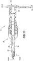
- an infusion adapter 10includes a connection portion 12 located at a first end 14, a first port 16 located at a first port end 18, and a second port 20 located at a second port end 22.
- Connection portion 12includes an anchor component 24 and a fluid channel 26 and a fluid channel 32, although only a single channel arrangement may also be utilized.
- First port 16includes a first port fluid channel 28 and second port 20 includes a second port fluid channel 30.
- the fluid channel 26 of connection portion 12is in fluid communication with first port fluid channel 28 of first port 16 such that a fluid may flow into infusion adapter 10 at first port 16, travel through first port fluid channel 28 to fluid channel 26 of connection portion 12 and out first end 14 of infusion adapter 10.
- connection portion 12is in fluid communication with second port fluid channel 30 of second port 20 such that a fluid may flow into infusion adapter 10 at first end 14 of connection portion 12, travel through fluid channel 32 to second port fluid channel 30 and out second port 20 of infusion adapter 10.
- infusion adapter 10may comprise a generally Y-shape. Further, it is contemplated that infusion adapter 10 may be made available in a variety of shapes and sizes as long as first port 16 is spaced a distance from second port 20 so that first port 16 may be connected to a syringe assembly containing a medication fluid and second port 20 may be connected to an intravenous line that is adapted for connection to a bloodstream of a patient as will be described in more detail below.
- infusion adapter 10may comprise a generally T-shape.
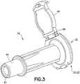
- infusion adapter 10may include an intravenous line connector 34 ( FIG. 3 ) that is removably connectable to a main body 36 ( FIG. 4 ) of infusion adapter 10.
- main body 36includes an intravenous line connector receiving end 38 having a first connection portion 40 as shown in FIG. 4 .
- intravenous line connector 34includes a main body receiving end 42 having a second connection portion 44 as shown in FIG. 3 .
- intravenous line connector 34includes an end cap 46 that is pivotable via a hinge portion 48 between an open position ( FIG. 3 ) to a closed position.
- Intravenous line connector 34may be connected to main body 36 by positioning main body receiving end 42 of intravenous line connector 34 into engagement with intravenous line connector receiving end 38 of main body 36.
- intravenous line connector 34may be secured to main body 36 by positioning second connection portion 44 of intravenous line connector 34 into engagement with first connection portion 40 of main body 36, and threadingly engaging first connection portion 40 and second connection portion 44.
- second connection portion 44 of intravenous line connector 34may be secured to first connection portion 40 of main body 36 using a press-fit, locking tapers, interference fit, snap-fit, ball detent, locking tabs, spring loaded locking mechanism, latch, adhesive, or other similar mechanism. In this manner, intravenous line connector 34 is locked to main body 36, i.e., significant relative movement between intravenous line connector 34 and main body 36 is prevented.
- intravenous line connector 34 and main body 36may be integrally formed.
- connection portion 12 of infusion adapter 10includes anchor component 24 and a puncturing point 60 disposed adjacent first end 14.
- anchor component 24includes a helical thread 50 which forms a threaded spike 52.
- the helical thread 50extends radially outward from the connection portion 12 and extends about the full length of the connection portion 12.
- the helical thread 50has two flank portions and a crest portion that is flat, although any other suitable thread form may be utilized.
- the starting and ending point of the helical thread 50may be tapered to form a gradual beginning and end to the helical thread 50. As shown in FIG.
- the helical thread 50extends circumferentially once around the connection portion 12 (360 degrees or one revolution), although any other suitable thread pitches may be utilized.
- the anchor component 24may include one or more helical threads 50.
- the helical thread 50allows for anchor component 24 to engage and interface the interior walls of an injection port 104 when connecting infusion adapter 10 to an infusion fluid container 102.
- the thread 50may self-tap and cut its own thread in the interior walls of injection port 104. In this manner, connection portion 12 of infusion adapter 10 is locked and anchored within injection port 104, i .
- threaded spike 52 of connection portion 12 of infusion adapter 10may threadingly engage corresponding threads located on the interior walls of injection port 104 of infusion fluid container 102.
- anchor component 24provides a means for connecting first end 14 of infusion adapter 10 to an injection port 104 of an infusion fluid container 102.
- the anchor component 24 of connection portion 12With the anchor component 24 of connection portion 12 connected to injection port 104 of the infusion fluid container 102, the anchor component 24 securely connects infusion adapter 10 to the infusion fluid container 102 such that disconnection of infusion adapter 10 from the infusion fluid container 102 is prevented.
- anchor component 24 of connection portion 12anchors infusion adapter 10 to injection port 104 of infusion fluid container 102, i.e., significant relative movement between infusion adapter 10 and injection port 104 of infusion fluid container 102 is prevented.
- anchor component 24prevents inadvertent and accidental removal of infusion adapter 10 from infusion fluid container 102 and provides a leakproof connection between infusion adapter 10 and infusion fluid container 102 during a drug transfer procedure. Furthermore, anchor component 24 reduces the spiking force required to pierce a fluid barrier member 106 of injection port 104 of the infusion fluid container 102.
- the connection portion 12engages the injection port 104 and is rotated such that the helical thread 50 engages the interior surface of the injection port 104 thereby providing a mechanical advantage to pierce the fluid barrier member 106 and to fully insert the connection portion 12 within the injection port 104.
- Infusion fluid container 102may also include a second port 108 and second fluid barrier 110.
- infusion adapter 10comprises a PhaSeal adapter which is compatible with a Becton Dickinson ("BD") PhaSeal TM System available from Becton, Dickinson and Company of Franklin Lakes, New Jersey.
- BDBecton Dickinson
- PhaSeal TM Systemavailable from Becton, Dickinson and Company of Franklin Lakes, New Jersey.
- intravenous therapy applicationsallow patients to receive infusion and medication treatment.
- therapymay include the administration of medications by IV using intravenous and subcutaneous or hypodermis routes, i.e., into the bloodstream and under the skin.
- medical treatments that intravenous therapy applications may provide to a patientinclude antibiotics, pain management medications, cancer treatments, and similar medications.
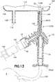
- a patientmay be provided with a fluid transfer system 100 that includes intravenous tubing 120 and a connector or injector adapter member 130 that is adapted to receive an injector and/or syringe assembly 140 containing a required medication fluid 142.
- anchor component 24 of infusion adapter 10in accordance with the present disclosure locks and anchors connection portion 12 of infusion adapter 10 within injection port 104, i.e., significant relative movement between infusion adapter 10 and injection port 104 of infusion fluid container 102 is prevented and disconnection of infusion adapter 10 from the infusion fluid container 102 is prevented as previously discussed.
- infusion adapter 10With infusion adapter 10 securely connected to injection port 104 of infusion fluid container 102 via anchor component 24, a patient or a medical practitioner is able to connect syringe assembly 140 to first port 16 of infusion adapter 10.
- a medical practitioneris able to connect syringe assembly 140 to first port 16 of infusion adapter 10 via connector 130 as shown in FIG. 13 .
- Connector 130could be a piercing member protection connector in accordance with the connector and protection device described in U.S. Patent Number 8,075,550, filed July 1, 2008 , entitled “Piercing Member Protection Device", the entire disclosure of which is hereby expressly incorporated herein by reference.
- a medication fluid 142 contained in syringe assembly 140can be injected into the infusion fluid container 102 via infusion adapter 10.
- the syringe assembly 140 and connector 130may then be disconnected from infusion adapter 10 and the infusion fluid container 102 may then be sent to nursing and is ready to be administered to a patient.
- an intravenous line or intravenous tubing 120may be connected to second port 20 of infusion adapter 10 as shown in FIG. 13 .
- the other end of the intravenous tubing 120is connected to a bloodstream of a patient P as shown in FIG. 13 . In this manner, a medication may be administered to the patient intravenously.
Landscapes
- Health & Medical Sciences (AREA)
- Vascular Medicine (AREA)
- Engineering & Computer Science (AREA)
- Anesthesiology (AREA)
- Biomedical Technology (AREA)
- Heart & Thoracic Surgery (AREA)
- Hematology (AREA)
- Life Sciences & Earth Sciences (AREA)
- Animal Behavior & Ethology (AREA)
- General Health & Medical Sciences (AREA)
- Public Health (AREA)
- Veterinary Medicine (AREA)
- Infusion, Injection, And Reservoir Apparatuses (AREA)
Description
- The present disclosure relates generally to a drug transfer assembly. More particularly, the present disclosure relates to an anchor component for securely connecting an infusion adapter to an intravenous bag for a drug transfer procedure.
- Intravenous therapy applications allow patients to receive infusion and medication treatment. For example, therapy may include the administration of medications by IV using intravenous and subcutaneous or hypodermis routes,i.e., into the bloodstream and under the skin. Examples of medical treatments that intravenous therapy applications may provide to a patient include antibiotics, pain management medications, cancer treatments, and similar medications.
- Medications may be packaged as "pre-filled" devices, wherein a syringe assembly is pre-filled with medication prior to being packaged and delivered to a patient. "Pre-filled" devices eliminate the need for a user to fill the device prior to injection.
- Certain drugs or medications are preferably provided in powder or dry form (such as a lyophilized form), and require reconstitution prior to administration. Lyophilized drugs, for example, typically are supplied in a freeze-dried form that needs to be mixed with a diluent to reconstitute the substance into a form that is suitable for injection. In addition, drugs may be provided as multipart systems that require mixing prior to administration. For example, one or more liquid components, such as flowable slurries, and one or more dry components, such as powdered or granular components, may be provided in separate containers that require mixing prior to administration.
- A patient may be provided with an intravenous system that includes intravenous tubing and a connector that is adapted to receive an injector and/or syringe assembly containing a required medication. In this manner, when a treatment is needed, a patient or a medical practitioner is able to connect a syringe assembly to the connector and then inject a medication intravenously into the patient via the injector and/or syringe assembly, the connector, and the intravenous tubing.
- When performing infusion, it is often necessary to inject a drug or other medical substance into the infusion fluid inside an infusion bag or other infusion fluid container. This is often done by means of penetrating a septum or other fluid barrier of an injection port on the infusion bag or on the infusion fluid line with a needle of a syringe filled with the medical fluid in question. However, it has been found that an unsecure connection between the syringe and the injection port of the infusion bag may cause problems such as accidental or inadvertent disconnection of the syringe from the infusion bag, pollution of the working environment because of leakage, and high forces required to pierce a fluid barrier of the injection port of the infusion bag.
US 2003/191445 A1 discloses the mixing of medical fluids, wherein a barb member engages with an outer surface of a transfer port of a fluid container.- The invention is defined by the subject-matter of claim 1. Further embodiments are defined in the dependent claims. In one embodiment, an infusion adapter for connection with an infusion fluid container includes a connection portion including an anchor component for connecting to an injection port of the infusion fluid container, and a first port adapted for connection with a syringe assembly containing a medication fluid. The first port is in fluid communication with the connection portion. The anchor component is configured to securely connect the infusion adapter to the infusion fluid container to substantially prevent disconnection of the infusion adapter from the infusion fluid container once the infusion adapter is connected to the infusion fluid container.
- The infusion adapter may further include a second port adapted for connection with an intravenous line adapted for connection to a bloodstream of a patient with the second port in fluid communication with the connection portion. The anchor component may be a helical thread. The helical thread may extend about an entire length of the connection portion. The helical thread may only extend one revolution circumferentially around the connection portion. The anchor component may reduce a force required by a user to pierce a fluid barrier member of the injection port of the infusion fluid container. The connection portion may define first and second fluid channels with the first channel in fluid communication with the first port and the second channel in fluid communication with the second port. The connection portion may be a spike having a puncturing point. The helical thread may be configured to self-tap a corresponding thread within a portion of the infusion fluid container when the connection portion is received by the infusion fluid container.
- In another embodiment, an adapter for connection with a container includes a connection portion configured to be connected to a first container with the connection portion including a helical thread. The adapter further includes at least one port adapted to be connected to a second container with the connection portion configured to be in fluid communication with the at least one port. The connection portion and the helical thread are configured to be received by a portion of the first container with the helical thread configured to securely connect the connection portion to the first container once the connection portion is connected to the first container.
- The helical thread may extend about an entire length of the connection portion. The helical thread may only extend one revolution circumferentially around the connection portion. The helical thread may reduce a force required by a user to pierce a fluid barrier member of the first container. The at least one port may include first and second ports with the first port configured to be connected with the second container and the second port configured to be connected with a third container. The connection portion may define first and second fluid channels with the first channel in fluid communication with the first port and the second channel in fluid communication with the second port. The connection portion may be a spike having a puncturing point. The helical thread may be configured to self-tap a corresponding thread within a portion of the first container when the connection portion is received by the first container.
- The above-mentioned and other features and advantages of this disclosure, and the manner of attaining them, will become more apparent and the disclosure itself will be better understood by reference to the following descriptions of embodiments of the disclosure taken in conjunction with the accompanying drawings, wherein:
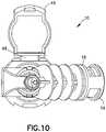
FIG. 1 is a perspective view of an infusion adapter in accordance with an embodiment of the present invention.FIG. 2 is another perspective view of the infusion adapter ofFIG. 1 in accordance with an embodiment of the present invention.FIG. 3 is a perspective view of an intravenous line connector of the infusion adapter ofFIG. 1 in accordance with an embodiment of the present invention.FIG. 4 is a perspective view of a main body of the infusion adapter ofFIG. 1 with the intravenous line connector ofFIG. 3 removed in accordance with an embodiment of the present invention.FIG. 5 is a side view of the infusion adapter ofFIG. 1 in accordance with an embodiment of the present invention.FIG. 6 is a top view of the infusion adapter ofFIG. 1 in accordance with an embodiment of the present invention.FIG. 7 is a rear view of the infusion adapter ofFIG. 1 in accordance with an embodiment of the present invention.FIG. 8 is a bottom view of the infusion adapter ofFIG. 1 in accordance with an embodiment of the present invention.FIG. 9 is a side view of the infusion adapter ofFIG. 1 in accordance with an embodiment of the present invention.FIG. 10 is a front view of the infusion adapter ofFIG. 1 in accordance with an embodiment of the present invention.FIG. 11 is a cross-sectional view taken along line11-11 of the infusion adapter ofFIG. 5 in accordance with an embodiment of the present invention.FIG. 12 is a cross-sectional view of the infusion adapter ofFIG. 1 with an anchor component of the connection portion of the infusion adapter anchored and securely connected to an injection port of an infusion fluid container in accordance with an embodiment of the present invention.FIG. 13 is a cross-sectional view of the infusion adapter ofFIG. 1 with an anchor component of the connection portion of the infusion adapter anchored and securely connected to an injection port of an infusion fluid container, with a syringe assembly containing a medication fluid connected to a first port of the infusion adapter via a connector, and with an intravenous line connected to a second port of the infusion adapter, the intravenous line connected at an opposite end to a bloodstream of a patient in accordance with an embodiment of the present invention.- Corresponding reference characters indicate corresponding parts throughout the several views. The exemplifications set out herein illustrate exemplary embodiments of the disclosure, and such exemplifications are not to be construed as limiting the scope of the disclosure in any manner.
- The following description is provided to enable those skilled in the art to make and use the described embodiments contemplated for carrying out the invention. Various modifications, equivalents, variations, and alternatives, however, will remain readily apparent to those skilled in the art. Any and all such modifications, variations, equivalents, and alternatives are intended to fall within the spirit and scope of the present invention.
- For purposes of the description hereinafter, the terms "upper", "lower", "right", "left", "vertical", "horizontal", "top", "bottom", "lateral", "longitudinal", and derivatives thereof shall relate to the invention as it is oriented in the drawing figures. However, it is to be understood that the invention may assume various alternative variations, except where expressly specified to the contrary. It is also to be understood that the specific devices illustrated in the attached drawings, and described in the following specification, are simply exemplary embodiments of the invention. Hence, specific dimensions and other physical characteristics related to the embodiments disclosed herein are not to be considered as limiting.
- Referring to
FIGS. 1-13 , aninfusion adapter 10 includes a connection portion12 located at a first end14, afirst port 16 located at afirst port end 18, and a second port20 located at a second port end22. Connection portion12 includes ananchor component 24 and afluid channel 26 and afluid channel 32, although only a single channel arrangement may also be utilized.First port 16 includes a firstport fluid channel 28 and second port20 includes a secondport fluid channel 30. As shown more clearly inFIGS. 12 and13 , thefluid channel 26 of connection portion12 is in fluid communication with firstport fluid channel 28 offirst port 16 such that a fluid may flow intoinfusion adapter 10 atfirst port 16, travel through firstport fluid channel 28 tofluid channel 26 of connection portion12 and out first end14 ofinfusion adapter 10. Thefluid channel 32 of connection portion12 is in fluid communication with secondport fluid channel 30 of second port20 such that a fluid may flow intoinfusion adapter 10 at first end14 of connection portion12, travel throughfluid channel 32 to secondport fluid channel 30 and out second port20 ofinfusion adapter 10. - Referring to
FIGS. 1-13 , in one embodiment,infusion adapter 10 may comprise a generally Y-shape. Further, it is contemplated thatinfusion adapter 10 may be made available in a variety of shapes and sizes as long asfirst port 16 is spaced a distance from second port20 so thatfirst port 16 may be connected to a syringe assembly containing a medication fluid and second port20 may be connected to an intravenous line that is adapted for connection to a bloodstream of a patient as will be described in more detail below. For example, in another embodiment,infusion adapter 10 may comprise a generally T-shape. - Referring to
FIGS. 3 and4 , in one embodiment,infusion adapter 10 may include an intravenous line connector34 (FIG. 3 ) that is removably connectable to a main body36 (FIG. 4 ) ofinfusion adapter 10. In such an embodiment,main body 36 includes an intravenous lineconnector receiving end 38 having afirst connection portion 40 as shown inFIG. 4 . Additionally,intravenous line connector 34 includes a mainbody receiving end 42 having asecond connection portion 44 as shown inFIG. 3 . Referring toFIG. 3 ,intravenous line connector 34 includes anend cap 46 that is pivotable via ahinge portion 48 between an open position(FIG. 3 ) to a closed position. Intravenous line connector 34 may be connected tomain body 36 by positioning mainbody receiving end 42 ofintravenous line connector 34 into engagement with intravenous lineconnector receiving end 38 ofmain body 36. In one embodiment,intravenous line connector 34 may be secured tomain body 36 by positioningsecond connection portion 44 ofintravenous line connector 34 into engagement withfirst connection portion 40 ofmain body 36, and threadingly engagingfirst connection portion 40 andsecond connection portion 44. In other embodiments,second connection portion 44 ofintravenous line connector 34 may be secured tofirst connection portion 40 ofmain body 36 using a press-fit, locking tapers, interference fit, snap-fit, ball detent, locking tabs, spring loaded locking mechanism, latch, adhesive, or other similar mechanism. In this manner,intravenous line connector 34 is locked tomain body 36,i.e., significant relative movement betweenintravenous line connector 34 andmain body 36 is prevented. In alternate embodiments,intravenous line connector 34 andmain body 36 may be integrally formed.- Referring to
FIGS. 1-13 , connection portion12 ofinfusion adapter 10 includesanchor component 24 and a puncturing point60 disposed adjacent first end14. In one embodiment,anchor component 24 includes ahelical thread 50 which forms a threaded spike52. Thehelical thread 50 extends radially outward from the connection portion12 and extends about the full length of the connection portion12. Thehelical thread 50 has two flank portions and a crest portion that is flat, although any other suitable thread form may be utilized. The starting and ending point of thehelical thread 50 may be tapered to form a gradual beginning and end to thehelical thread 50. As shown inFIG. 1 , thehelical thread 50 extends circumferentially once around the connection portion12 (360 degrees or one revolution), although any other suitable thread pitches may be utilized. Further, although a singlehelical thread 50 is utilized, theanchor component 24 may include one or morehelical threads 50. Thehelical thread 50 allows foranchor component 24 to engage and interface the interior walls of aninjection port 104 when connectinginfusion adapter 10 to an infusionfluid container 102. In one embodiment, thethread 50 may self-tap and cut its own thread in the interior walls ofinjection port 104. In this manner, connection portion12 ofinfusion adapter 10 is locked and anchored withininjection port 104,i.e., significant relative movement betweeninfusion adapter 10 andinjection port 104 of infusionfluid container 102 is prevented and disconnection ofinfusion adapter 10 from the infusionfluid container 102 is prevented. In an alternative embodiment, threaded spike52 of connection portion12 ofinfusion adapter 10 may threadingly engage corresponding threads located on the interior walls ofinjection port 104 of infusionfluid container 102. - Referring to
FIGS. 12 and13 ,anchor component 24 provides a means for connecting first end14 ofinfusion adapter 10 to aninjection port 104 of an infusionfluid container 102. With theanchor component 24 of connection portion12 connected toinjection port 104 of the infusionfluid container 102, theanchor component 24 securely connectsinfusion adapter 10 to the infusionfluid container 102 such that disconnection ofinfusion adapter 10 from the infusionfluid container 102 is prevented. Additionally,anchor component 24 of connection portion12anchors infusion adapter 10 toinjection port 104 of infusionfluid container 102,i.e., significant relative movement betweeninfusion adapter 10 andinjection port 104 of infusionfluid container 102 is prevented. In this manner,anchor component 24 prevents inadvertent and accidental removal ofinfusion adapter 10 from infusionfluid container 102 and provides a leakproof connection betweeninfusion adapter 10 and infusionfluid container 102 during a drug transfer procedure. Furthermore,anchor component 24 reduces the spiking force required to pierce afluid barrier member 106 ofinjection port 104 of the infusionfluid container 102. In particular, the connection portion12 engages theinjection port 104 and is rotated such that thehelical thread 50 engages the interior surface of theinjection port 104 thereby providing a mechanical advantage to pierce thefluid barrier member 106 and to fully insert the connection portion12 within theinjection port 104.Infusion fluid container 102 may also include asecond port 108 and secondfluid barrier 110. - In one embodiment,
infusion adapter 10 comprises a PhaSeal adapter which is compatible with a Becton Dickinson ("BD") PhaSeal™ System available from Becton, Dickinson and Company of Franklin Lakes, New Jersey. - As previously discussed, intravenous therapy applications allow patients to receive infusion and medication treatment. For example, therapy may include the administration of medications by IV using intravenous and subcutaneous or hypodermis routes,i.e., into the bloodstream and under the skin. Examples of medical treatments that intravenous therapy applications may provide to a patient include antibiotics, pain management medications, cancer treatments, and similar medications.
- Referring to
FIG. 13 , a patient may be provided with afluid transfer system 100 that includesintravenous tubing 120 and a connector orinjector adapter member 130 that is adapted to receive an injector and/orsyringe assembly 140 containing a requiredmedication fluid 142. - When performing infusion, it is often necessary to inject a drug or other medical substance into an infusion fluid located inside an infusion bag or other infusion
fluid container 102. This is often done by means of penetrating a septum orfluid barrier member 106 of aninjection port 104 on the infusionfluid container 102. - Referring to
FIGS. 12 and13 , when a treatment is needed, a patient or a medical practitioner is able to spike or piercefluid barrier member 106 ofinjection port 104 of infusionfluid container 102 with puncturing point60 andanchor component 24 of connection portion12 ofinfusion adapter 10. Advantageously,anchor component 24 ofinfusion adapter 10 in accordance with the present disclosure locks and anchors connection portion12 ofinfusion adapter 10 withininjection port 104,i.e., significant relative movement betweeninfusion adapter 10 andinjection port 104 of infusionfluid container 102 is prevented and disconnection ofinfusion adapter 10 from the infusionfluid container 102 is prevented as previously discussed. - With
infusion adapter 10 securely connected toinjection port 104 of infusionfluid container 102 viaanchor component 24, a patient or a medical practitioner is able to connectsyringe assembly 140 tofirst port 16 ofinfusion adapter 10. In one embodiment, a medical practitioner is able to connectsyringe assembly 140 tofirst port 16 ofinfusion adapter 10 viaconnector 130 as shown inFIG. 13 .Connector 130 could be a piercing member protection connector in accordance with the connector and protection device described inU.S. Patent Number 8,075,550, filed July 1, 2008 , entitled "Piercing Member Protection Device", the entire disclosure of which is hereby expressly incorporated herein by reference. - With
syringe assembly 140 connected tofirst port 16, amedication fluid 142 contained insyringe assembly 140 can be injected into the infusionfluid container 102 viainfusion adapter 10. Thesyringe assembly 140 andconnector 130 may then be disconnected frominfusion adapter 10 and the infusionfluid container 102 may then be sent to nursing and is ready to be administered to a patient. For example, an intravenous line orintravenous tubing 120 may be connected to second port20 ofinfusion adapter 10 as shown inFIG. 13 . The other end of theintravenous tubing 120 is connected to a bloodstream of a patientP as shown inFIG. 13 . In this manner, a medication may be administered to the patient intravenously. - While this disclosure has been described as having exemplary designs, the present disclosure can be further modified within the spirit and scope of this disclosure. This application is therefore intended to cover any variations, uses, or adaptations of the disclosure using its general principles. Further, this application is intended to cover such departures from the present disclosure as come within known or customary practice in the art to which this disclosure pertains and which fall within the limits of the appended claims.
Claims (5)
- An infusion adapter (10) for connection with an infusion fluid container (102), the infusion adapter (10) comprising:a connection portion (12) including an anchor component (24) for connecting to an injection port (104) of the infusion fluid container (102), the connection portion (12) comprising a spike (52) extending from a proximal end to a puncturing point and the anchor component (24) further comprising a helical thread (50) extending radially outward from the spike (52);a first port (16) adapted for connection with a syringe assembly containing a medication fluid, the first port (16) in fluid communication with the connection portion (12) via a first passageway extending from the first port (16) to a distal opening positioned adjacent to the puncturing point of the spike (52); anda second port (20) adapted for connection with an intravenous line, the second port (20) in fluid communication with the connection portion (12) via a second passageway extending from the second port (20) to a distal opening, the distal opening of the second passageway axially spaced from the distal opening of the first passageway,wherein the distal openings of the first passageway and the second passageway are radially opposed at the distal end of the spike (52),wherein the helical thread (50) of the spike (52) is configured to interfere with the injection port (104) of the infusion fluid container (102) to substantially prevent disconnection of the infusion adapter (10) from the infusion fluid container (102) once the infusion adapter (10) is connected to the infusion fluid container (102),characterized in that a circumferential path of the helical thread (50) extends axially from the proximal end of the spike (52) to the puncturing point of the spike (52).
- The infusion adapter (10) of claim 1, wherein the helical thread (50) only extends one revolution circumferentially around the connection portion (12).
- The infusion adapter (10) of any of claims 1-2, wherein the anchor component (24) reduces a force required by a user to pierce a fluid barrier member (106) of the injection port (104) of the infusion fluid container (102) due to the rotational movement of the helical thread (50).
- The infusion adapter (10) of any of claims 1-3, wherein the helical thread (50) is configured to self-tap a corresponding pathway within an internal diameter of the injection port (104) when the spike (52) is inserted into the injection port (104).
- The infusion adapter (10) of any of claims 1-4, wherein the helical thread (50) reduces a force required by a user to pierce a fluid barrier member (106) of the infusion fluid container (102).
Applications Claiming Priority (3)
| Application Number | Priority Date | Filing Date | Title |
|---|---|---|---|
| US201261731902P | 2012-11-30 | 2012-11-30 | |
| EP13811302.2AEP2925385B1 (en) | 2012-11-30 | 2013-11-27 | Infusion adapter for drug transfer assembly |
| PCT/US2013/072122WO2014085517A1 (en) | 2012-11-30 | 2013-11-27 | Infusion adapter for drug transfer assembly |
Related Parent Applications (2)
| Application Number | Title | Priority Date | Filing Date |
|---|---|---|---|
| EP13811302.2ADivision-IntoEP2925385B1 (en) | 2012-11-30 | 2013-11-27 | Infusion adapter for drug transfer assembly |
| EP13811302.2ADivisionEP2925385B1 (en) | 2012-11-30 | 2013-11-27 | Infusion adapter for drug transfer assembly |
Publications (2)
| Publication Number | Publication Date |
|---|---|
| EP3650059A1 EP3650059A1 (en) | 2020-05-13 |
| EP3650059B1true EP3650059B1 (en) | 2022-07-27 |
Family
ID=50824258
Family Applications (2)
| Application Number | Title | Priority Date | Filing Date |
|---|---|---|---|
| EP19207718.8AActiveEP3650059B1 (en) | 2012-11-30 | 2013-11-27 | Infusion adapter for drug transfer assembly |
| EP13811302.2AActiveEP2925385B1 (en) | 2012-11-30 | 2013-11-27 | Infusion adapter for drug transfer assembly |
Family Applications After (1)
| Application Number | Title | Priority Date | Filing Date |
|---|---|---|---|
| EP13811302.2AActiveEP2925385B1 (en) | 2012-11-30 | 2013-11-27 | Infusion adapter for drug transfer assembly |
Country Status (10)
| Country | Link |
|---|---|
| US (2) | US9550024B2 (en) |
| EP (2) | EP3650059B1 (en) |
| JP (1) | JP6113859B2 (en) |
| CN (2) | CN107929858B (en) |
| AU (1) | AU2013352251B2 (en) |
| CA (1) | CA2892760C (en) |
| ES (2) | ES2927733T3 (en) |
| IL (2) | IL238950B (en) |
| MX (2) | MX374107B (en) |
| WO (1) | WO2014085517A1 (en) |
Families Citing this family (59)
| Publication number | Priority date | Publication date | Assignee | Title |
|---|---|---|---|---|
| IL201323A0 (en) | 2009-10-01 | 2010-05-31 | Medimop Medical Projects Ltd | Fluid transfer device for assembling a vial with pre-attached female connector |
| IL202070A0 (en) | 2009-11-12 | 2010-06-16 | Medimop Medical Projects Ltd | Inline liquid drug medical device |
| IL209290A0 (en) | 2010-11-14 | 2011-01-31 | Medimop Medical Projects Ltd | Inline liquid drug medical device having rotary flow control member |
| IL215699A0 (en) | 2011-10-11 | 2011-12-29 | Medimop Medical Projects Ltd | Liquid drug reconstitution assemblage for use with iv bag and drug vial |
| USD720451S1 (en) | 2012-02-13 | 2014-12-30 | Medimop Medical Projects Ltd. | Liquid drug transfer assembly |
| USD737436S1 (en) | 2012-02-13 | 2015-08-25 | Medimop Medical Projects Ltd. | Liquid drug reconstitution assembly |
| IL219065A0 (en) | 2012-04-05 | 2012-07-31 | Medimop Medical Projects Ltd | Fluid transfer device with manual operated cartridge release arrangement |
| IL221634A0 (en) | 2012-08-26 | 2012-12-31 | Medimop Medical Projects Ltd | Universal drug vial adapter |
| IL221635A0 (en) | 2012-08-26 | 2012-12-31 | Medimop Medical Projects Ltd | Drug vial mixing and transfer device for use with iv bag and drug vial |
| DK2872100T3 (en) | 2012-09-13 | 2017-07-10 | Medimop Medical Projects Ltd | Telescopic female adapter for drug ampoule |
| USD734868S1 (en) | 2012-11-27 | 2015-07-21 | Medimop Medical Projects Ltd. | Drug vial adapter with downwardly depending stopper |
| IL225734A0 (en) | 2013-04-14 | 2013-09-30 | Medimop Medical Projects Ltd | Ready-to-use drug vial assemblages including drug vial and drug vial closure having fluid transfer member, and drug vial closure therefor |
| CN105228676B (en) | 2013-05-10 | 2018-01-05 | 麦迪麦珀医疗工程有限公司 | Include the medical treatment device of the vial adapter with inline dry kit |
| DE212014000169U1 (en) | 2013-08-07 | 2016-03-14 | Medimop Medical Projects Ltd. | Fluid transfer devices for use with infusion fluid containers |
| USD767124S1 (en) | 2013-08-07 | 2016-09-20 | Medimop Medical Projects Ltd. | Liquid transfer device with integral vial adapter |
| USD765837S1 (en) | 2013-08-07 | 2016-09-06 | Medimop Medical Projects Ltd. | Liquid transfer device with integral vial adapter |
| US10207074B2 (en) | 2013-09-04 | 2019-02-19 | Fisher & Paykel Healthcare Limited | Float retention arrangement for humidification chamber |
| USD734456S1 (en)* | 2014-02-03 | 2015-07-14 | Nordson Corporation | Hub for a medical applicator |
| USD794183S1 (en) | 2014-03-19 | 2017-08-08 | Medimop Medical Projects Ltd. | Dual ended liquid transfer spike |
| USD757933S1 (en) | 2014-09-11 | 2016-05-31 | Medimop Medical Projects Ltd. | Dual vial adapter assemblage |
| JP6358724B2 (en) | 2015-01-05 | 2018-07-18 | ウエスト・ファーマ.サービシーズ・イスラエル,リミテッド | Dual vial adapter assembly with easy removable pill adapter to ensure accurate use |
| US11278664B2 (en) | 2015-01-09 | 2022-03-22 | Becton Dickinson and Company Limited | Infusion adapter |
| WO2017009822A1 (en) | 2015-07-16 | 2017-01-19 | Medimop Medical Projects Ltd | Liquid drug transfer devices for secure telescopic snap fit on injection vials |
| USD801522S1 (en) | 2015-11-09 | 2017-10-31 | Medimop Medical Projects Ltd. | Fluid transfer assembly |
| CN115721558A (en) | 2015-11-25 | 2023-03-03 | 西部制药服务以色列有限公司 | Dual vial adapter assembly comprising a drug vial adapter having a self-sealing inlet valve |
| US11344220B2 (en) | 2016-05-13 | 2022-05-31 | Becton, Dickinson And Company | Invasive medical device cover with magnet |
| IL245800A0 (en) | 2016-05-24 | 2016-08-31 | West Pharma Services Il Ltd | Dual vial adapter assemblages including identical twin vial adapters |
| IL245803A0 (en) | 2016-05-24 | 2016-08-31 | West Pharma Services Il Ltd | Dual vial adapter assemblages including vented drug vial adapter and vented liquid vial adapter |
| IL246073A0 (en) | 2016-06-06 | 2016-08-31 | West Pharma Services Il Ltd | Fluid transfer devices for use with drug pump cartridge having slidable driving plunger |
| IL247376A0 (en) | 2016-08-21 | 2016-12-29 | Medimop Medical Projects Ltd | Syringe assembly |
| US10032552B2 (en)* | 2016-08-30 | 2018-07-24 | Becton, Dickinson And Company | Cover for tissue penetrating device with integrated magnets and magnetic shielding |
| USD832430S1 (en) | 2016-11-15 | 2018-10-30 | West Pharma. Services IL, Ltd. | Dual vial adapter assemblage |
| IL249408A0 (en) | 2016-12-06 | 2017-03-30 | Medimop Medical Projects Ltd | Liquid transfer device for use with infusion liquid container and pincers-like hand tool for use therewith for releasing intact drug vial therefrom |
| EP3568117B1 (en) | 2017-01-12 | 2021-03-03 | Becton Dickinson and Company Limited | Closed system stress resistant membrane |
| DE102017205188A1 (en) | 2017-03-28 | 2018-10-04 | B. Braun Melsungen Ag | Safety device for securing an infusion device |
| IL251458A0 (en) | 2017-03-29 | 2017-06-29 | Medimop Medical Projects Ltd | User actuated liquid drug transfer devices for use in ready-to-use (rtu) liquid drug transfer assemblages |
| IL254802A0 (en) | 2017-09-29 | 2017-12-31 | Medimop Medical Projects Ltd | Dual vial adapter assemblages with twin vented female vial adapters |
| USD894378S1 (en)* | 2017-11-03 | 2020-08-25 | Medline Industries, Inc. | Enteral feeding valve |
| KR101973972B1 (en)* | 2017-11-27 | 2019-04-30 | 주식회사한빛엠디 | Drip Chamber of Injection Set |
| USD888945S1 (en) | 2018-04-04 | 2020-06-30 | Becton Dickinson and Company Limited | Medical connector |
| USD873996S1 (en) | 2018-04-04 | 2020-01-28 | Becton Dickinson and Company Limited | Medical syringe adapter |
| USD877900S1 (en) | 2018-04-04 | 2020-03-10 | Becton Dickinson and Company Limited | Medical infusion adapter |
| USD908872S1 (en) | 2018-04-04 | 2021-01-26 | Becton Dickinson and Company Limited | Medical vial access device |
| JP1630477S (en) | 2018-07-06 | 2019-05-07 | ||
| USD923812S1 (en) | 2019-01-16 | 2021-06-29 | West Pharma. Services IL, Ltd. | Medication mixing apparatus |
| JP1648075S (en) | 2019-01-17 | 2019-12-16 | ||
| JP7209849B2 (en) | 2019-01-18 | 2023-01-20 | ウェスト・ファーマ・サービシーズ・アイエル・リミテッド | Liquid transfer device for use with IV bottles |
| US11918542B2 (en) | 2019-01-31 | 2024-03-05 | West Pharma. Services IL, Ltd. | Liquid transfer device |
| WO2020168175A1 (en)* | 2019-02-15 | 2020-08-20 | Yukon Medical, Llc | Transfer device for use with infusion liquid container |
| US20200282134A1 (en)* | 2019-03-04 | 2020-09-10 | Carefusion 303, Inc. | Iv spike for use with non-iso compliant iv container |
| US11266779B2 (en)* | 2019-03-04 | 2022-03-08 | Carefusion 303, Inc. | IV set spike with enhanced removal force |
| JP7284289B2 (en) | 2019-04-09 | 2023-05-30 | ウェスト ファーマ サービシーズ イスラエル リミテッド | Infusion device with integrated syringe |
| KR20240122586A (en) | 2019-04-30 | 2024-08-12 | 웨스트 파마. 서비시즈 일, 리미티드 | Liquid transfer device with dual lumen iv spike |
| US12280238B2 (en) | 2019-11-26 | 2025-04-22 | Emory University | IV administration system configured to prevent self-inflicted injury |
| USD956958S1 (en)* | 2020-07-13 | 2022-07-05 | West Pharma. Services IL, Ltd. | Liquid transfer device |
| US11690787B2 (en) | 2020-08-25 | 2023-07-04 | Becton, Dickinson And Company | Drug transfer adapter |
| US20220296873A1 (en)* | 2021-03-22 | 2022-09-22 | David Liu | Connector assembly for use in medical fluid lines |
| USD970727S1 (en) | 2022-07-27 | 2022-11-22 | Omar Hassad | Intravenous Y-shaped adapter |
| US20250269107A1 (en)* | 2024-02-22 | 2025-08-28 | Becton, Dickinson And Company | System for Infusion of Hazardous Drugs |
Family Cites Families (19)
| Publication number | Priority date | Publication date | Assignee | Title |
|---|---|---|---|---|
| US3755697A (en) | 1971-11-26 | 1973-08-28 | Hewlett Packard Co | Light-emitting diode driver |
| US3822700A (en)* | 1973-03-16 | 1974-07-09 | M Pennington | Intravenous solution dispenser |
| GB8709535D0 (en)* | 1987-04-22 | 1987-05-28 | Finsbury Instr Ltd | Acetabulum |
| US5755697A (en)* | 1995-11-22 | 1998-05-26 | Jones; Calvin E. | Self-tunneling, self-securing percutaneous catheterization device and method of use thereof |
| AU2003213816B2 (en)* | 2002-03-08 | 2008-06-05 | Vicentra B.V. | Low profile, pivotal connection infusion assembly |
| US7744581B2 (en)* | 2002-04-08 | 2010-06-29 | Carmel Pharma Ab | Device and method for mixing medical fluids |
| ATE387931T1 (en)* | 2002-07-09 | 2008-03-15 | Carmel Pharma Ab | DEVICE FOR INJECTING MEDICAL SUBSTANCES |
| WO2004004806A1 (en) | 2002-07-09 | 2004-01-15 | Carmel Pharma Ab | A coupling component for transmitting medical substances |
| SE523001C2 (en)* | 2002-07-09 | 2004-03-23 | Carmel Pharma Ab | Coupling component for transmitting medical substances, comprises connecting mechanism for releasable connection to second coupling component having further channel for creating coupling, where connecting mechanism is thread |
| DE20302788U1 (en)* | 2003-02-20 | 2004-06-24 | Nietzke, Mathias | Tubing system for an infusion bottle, comprises connecting sites in the form of insertion and insertion-rotating connections with fixing locks or blocking elements, especially clamps |
| US7740288B2 (en)* | 2005-05-09 | 2010-06-22 | Northgate Technologies Inc. | High-flow luer lock connector for a luer lock connection |
| JP2007236438A (en) | 2006-03-06 | 2007-09-20 | Jms Co Ltd | Medical bottle needle |
| GB0620059D0 (en)* | 2006-10-10 | 2006-11-22 | Ucb Sa | Therapeutic agents |
| US8075550B2 (en) | 2008-07-01 | 2011-12-13 | Carmel Pharma Ab | Piercing member protection device |
| BRPI0918416A2 (en)* | 2008-09-12 | 2018-07-24 | Nestec Sa | container closure |
| GB0816704D0 (en)* | 2008-09-12 | 2008-10-22 | Link Ltd B | Medical device |
| ES2441411T3 (en) | 2008-12-15 | 2014-02-04 | Carmel Pharma Ab | Connection arrangement and procedure for connecting a medical device to the connection arrangement |
| CN201370846Y (en)* | 2009-03-26 | 2009-12-30 | 邹莉 | Spiral type bottle stopper puncture needle |
| US8366658B2 (en)* | 2010-05-06 | 2013-02-05 | Becton, Dickinson And Company | Systems and methods for providing a closed venting hazardous drug IV set |
- 2013
- 2013-11-27EPEP19207718.8Apatent/EP3650059B1/enactiveActive
- 2013-11-27CNCN201711289546.3Apatent/CN107929858B/enactiveActive
- 2013-11-27MXMX2015006503Apatent/MX374107B/enactiveIP Right Grant
- 2013-11-27CNCN201380069060.2Apatent/CN104884103B/enactiveActive
- 2013-11-27ESES19207718Tpatent/ES2927733T3/enactiveActive
- 2013-11-27ESES13811302Tpatent/ES2778867T3/enactiveActive
- 2013-11-27JPJP2015545207Apatent/JP6113859B2/enactiveActive
- 2013-11-27EPEP13811302.2Apatent/EP2925385B1/enactiveActive
- 2013-11-27AUAU2013352251Apatent/AU2013352251B2/enactiveActive
- 2013-11-27CACA2892760Apatent/CA2892760C/enactiveActive
- 2013-11-27WOPCT/US2013/072122patent/WO2014085517A1/enactiveApplication Filing
- 2013-11-27USUS14/091,506patent/US9550024B2/enactiveActive
- 2015
- 2015-05-21ILIL238950Apatent/IL238950B/enactiveIP Right Grant
- 2015-05-22MXMX2020007189Apatent/MX2020007189A/enunknown
- 2016
- 2016-12-12USUS15/375,949patent/US10149937B2/enactiveActive
- 2020
- 2020-08-03ILIL276468Apatent/IL276468B/enunknown
Also Published As
| Publication number | Publication date |
|---|---|
| IL238950B (en) | 2020-09-30 |
| JP6113859B2 (en) | 2017-04-12 |
| CN107929858A (en) | 2018-04-20 |
| US9550024B2 (en) | 2017-01-24 |
| MX2015006503A (en) | 2016-02-16 |
| WO2014085517A1 (en) | 2014-06-05 |
| EP2925385A1 (en) | 2015-10-07 |
| MX2020007189A (en) | 2020-08-31 |
| US20140150911A1 (en) | 2014-06-05 |
| CN104884103A (en) | 2015-09-02 |
| CN104884103B (en) | 2018-01-02 |
| US10149937B2 (en) | 2018-12-11 |
| IL276468A (en) | 2020-09-30 |
| EP2925385B1 (en) | 2020-01-01 |
| MX374107B (en) | 2025-03-05 |
| ES2927733T3 (en) | 2022-11-10 |
| CN107929858B (en) | 2021-03-12 |
| ES2778867T3 (en) | 2020-08-12 |
| US20170087297A1 (en) | 2017-03-30 |
| AU2013352251A1 (en) | 2015-06-11 |
| CA2892760A1 (en) | 2014-06-05 |
| JP2015536212A (en) | 2015-12-21 |
| AU2013352251B2 (en) | 2016-11-03 |
| IL238950A0 (en) | 2015-07-30 |
| CA2892760C (en) | 2017-07-11 |
| EP3650059A1 (en) | 2020-05-13 |
| IL276468B (en) | 2021-08-31 |
Similar Documents
| Publication | Publication Date | Title |
|---|---|---|
| US10149937B2 (en) | Infusion adapter for drug transfer assembly | |
| US11911593B2 (en) | Infusion adapter | |
| US8905994B1 (en) | Valve assembly for use with liquid container and drug vial | |
| US20040260266A1 (en) | Method and device for transferring fluid | |
| US20120046618A1 (en) | Needle and syringe | |
| EP2895234A1 (en) | Adapter cap for drug transfer assembly |
Legal Events
| Date | Code | Title | Description |
|---|---|---|---|
| PUAI | Public reference made under article 153(3) epc to a published international application that has entered the european phase | Free format text:ORIGINAL CODE: 0009012 | |
| STAA | Information on the status of an ep patent application or granted ep patent | Free format text:STATUS: THE APPLICATION HAS BEEN PUBLISHED | |
| AC | Divisional application: reference to earlier application | Ref document number:2925385 Country of ref document:EP Kind code of ref document:P | |
| AK | Designated contracting states | Kind code of ref document:A1 Designated state(s):AL AT BE BG CH CY CZ DE DK EE ES FI FR GB GR HR HU IE IS IT LI LT LU LV MC MK MT NL NO PL PT RO RS SE SI SK SM TR | |
| STAA | Information on the status of an ep patent application or granted ep patent | Free format text:STATUS: REQUEST FOR EXAMINATION WAS MADE | |
| 17P | Request for examination filed | Effective date:20201104 | |
| RBV | Designated contracting states (corrected) | Designated state(s):AL AT BE BG CH CY CZ DE DK EE ES FI FR GB GR HR HU IE IS IT LI LT LU LV MC MK MT NL NO PL PT RO RS SE SI SK SM TR | |
| GRAP | Despatch of communication of intention to grant a patent | Free format text:ORIGINAL CODE: EPIDOSNIGR1 | |
| STAA | Information on the status of an ep patent application or granted ep patent | Free format text:STATUS: GRANT OF PATENT IS INTENDED | |
| INTG | Intention to grant announced | Effective date:20220224 | |
| GRAS | Grant fee paid | Free format text:ORIGINAL CODE: EPIDOSNIGR3 | |
| GRAA | (expected) grant | Free format text:ORIGINAL CODE: 0009210 | |
| STAA | Information on the status of an ep patent application or granted ep patent | Free format text:STATUS: THE PATENT HAS BEEN GRANTED | |
| AC | Divisional application: reference to earlier application | Ref document number:2925385 Country of ref document:EP Kind code of ref document:P | |
| AK | Designated contracting states | Kind code of ref document:B1 Designated state(s):AL AT BE BG CH CY CZ DE DK EE ES FI FR GB GR HR HU IE IS IT LI LT LU LV MC MK MT NL NO PL PT RO RS SE SI SK SM TR | |
| REG | Reference to a national code | Ref country code:CH Ref legal event code:EP | |
| REG | Reference to a national code | Ref country code:AT Ref legal event code:REF Ref document number:1506651 Country of ref document:AT Kind code of ref document:T Effective date:20220815 | |
| REG | Reference to a national code | Ref country code:DE Ref legal event code:R096 Ref document number:602013082196 Country of ref document:DE | |
| REG | Reference to a national code | Ref country code:IE Ref legal event code:FG4D | |
| REG | Reference to a national code | Ref country code:LT Ref legal event code:MG9D | |
| REG | Reference to a national code | Ref country code:NL Ref legal event code:MP Effective date:20220727 | |
| PG25 | Lapsed in a contracting state [announced via postgrant information from national office to epo] | Ref country code:SE Free format text:LAPSE BECAUSE OF FAILURE TO SUBMIT A TRANSLATION OF THE DESCRIPTION OR TO PAY THE FEE WITHIN THE PRESCRIBED TIME-LIMIT Effective date:20220727 Ref country code:RS Free format text:LAPSE BECAUSE OF FAILURE TO SUBMIT A TRANSLATION OF THE DESCRIPTION OR TO PAY THE FEE WITHIN THE PRESCRIBED TIME-LIMIT Effective date:20220727 Ref country code:PT Free format text:LAPSE BECAUSE OF FAILURE TO SUBMIT A TRANSLATION OF THE DESCRIPTION OR TO PAY THE FEE WITHIN THE PRESCRIBED TIME-LIMIT Effective date:20221128 Ref country code:NO Free format text:LAPSE BECAUSE OF FAILURE TO SUBMIT A TRANSLATION OF THE DESCRIPTION OR TO PAY THE FEE WITHIN THE PRESCRIBED TIME-LIMIT Effective date:20221027 Ref country code:NL Free format text:LAPSE BECAUSE OF FAILURE TO SUBMIT A TRANSLATION OF THE DESCRIPTION OR TO PAY THE FEE WITHIN THE PRESCRIBED TIME-LIMIT Effective date:20220727 Ref country code:LV Free format text:LAPSE BECAUSE OF FAILURE TO SUBMIT A TRANSLATION OF THE DESCRIPTION OR TO PAY THE FEE WITHIN THE PRESCRIBED TIME-LIMIT Effective date:20220727 Ref country code:LT Free format text:LAPSE BECAUSE OF FAILURE TO SUBMIT A TRANSLATION OF THE DESCRIPTION OR TO PAY THE FEE WITHIN THE PRESCRIBED TIME-LIMIT Effective date:20220727 Ref country code:FI Free format text:LAPSE BECAUSE OF FAILURE TO SUBMIT A TRANSLATION OF THE DESCRIPTION OR TO PAY THE FEE WITHIN THE PRESCRIBED TIME-LIMIT Effective date:20220727 | |
| REG | Reference to a national code | Ref country code:AT Ref legal event code:MK05 Ref document number:1506651 Country of ref document:AT Kind code of ref document:T Effective date:20220727 | |
| PG25 | Lapsed in a contracting state [announced via postgrant information from national office to epo] | Ref country code:PL Free format text:LAPSE BECAUSE OF FAILURE TO SUBMIT A TRANSLATION OF THE DESCRIPTION OR TO PAY THE FEE WITHIN THE PRESCRIBED TIME-LIMIT Effective date:20220727 Ref country code:IS Free format text:LAPSE BECAUSE OF FAILURE TO SUBMIT A TRANSLATION OF THE DESCRIPTION OR TO PAY THE FEE WITHIN THE PRESCRIBED TIME-LIMIT Effective date:20221127 Ref country code:HR Free format text:LAPSE BECAUSE OF FAILURE TO SUBMIT A TRANSLATION OF THE DESCRIPTION OR TO PAY THE FEE WITHIN THE PRESCRIBED TIME-LIMIT Effective date:20220727 Ref country code:GR Free format text:LAPSE BECAUSE OF FAILURE TO SUBMIT A TRANSLATION OF THE DESCRIPTION OR TO PAY THE FEE WITHIN THE PRESCRIBED TIME-LIMIT Effective date:20221028 | |
| PG25 | Lapsed in a contracting state [announced via postgrant information from national office to epo] | Ref country code:SM Free format text:LAPSE BECAUSE OF FAILURE TO SUBMIT A TRANSLATION OF THE DESCRIPTION OR TO PAY THE FEE WITHIN THE PRESCRIBED TIME-LIMIT Effective date:20220727 Ref country code:RO Free format text:LAPSE BECAUSE OF FAILURE TO SUBMIT A TRANSLATION OF THE DESCRIPTION OR TO PAY THE FEE WITHIN THE PRESCRIBED TIME-LIMIT Effective date:20220727 Ref country code:DK Free format text:LAPSE BECAUSE OF FAILURE TO SUBMIT A TRANSLATION OF THE DESCRIPTION OR TO PAY THE FEE WITHIN THE PRESCRIBED TIME-LIMIT Effective date:20220727 Ref country code:CZ Free format text:LAPSE BECAUSE OF FAILURE TO SUBMIT A TRANSLATION OF THE DESCRIPTION OR TO PAY THE FEE WITHIN THE PRESCRIBED TIME-LIMIT Effective date:20220727 Ref country code:AT Free format text:LAPSE BECAUSE OF FAILURE TO SUBMIT A TRANSLATION OF THE DESCRIPTION OR TO PAY THE FEE WITHIN THE PRESCRIBED TIME-LIMIT Effective date:20220727 | |
| REG | Reference to a national code | Ref country code:DE Ref legal event code:R097 Ref document number:602013082196 Country of ref document:DE | |
| PG25 | Lapsed in a contracting state [announced via postgrant information from national office to epo] | Ref country code:SK Free format text:LAPSE BECAUSE OF FAILURE TO SUBMIT A TRANSLATION OF THE DESCRIPTION OR TO PAY THE FEE WITHIN THE PRESCRIBED TIME-LIMIT Effective date:20220727 Ref country code:EE Free format text:LAPSE BECAUSE OF FAILURE TO SUBMIT A TRANSLATION OF THE DESCRIPTION OR TO PAY THE FEE WITHIN THE PRESCRIBED TIME-LIMIT Effective date:20220727 | |
| PLBE | No opposition filed within time limit | Free format text:ORIGINAL CODE: 0009261 | |
| STAA | Information on the status of an ep patent application or granted ep patent | Free format text:STATUS: NO OPPOSITION FILED WITHIN TIME LIMIT | |
| PG25 | Lapsed in a contracting state [announced via postgrant information from national office to epo] | Ref country code:MC Free format text:LAPSE BECAUSE OF FAILURE TO SUBMIT A TRANSLATION OF THE DESCRIPTION OR TO PAY THE FEE WITHIN THE PRESCRIBED TIME-LIMIT Effective date:20220727 Ref country code:AL Free format text:LAPSE BECAUSE OF FAILURE TO SUBMIT A TRANSLATION OF THE DESCRIPTION OR TO PAY THE FEE WITHIN THE PRESCRIBED TIME-LIMIT Effective date:20220727 | |
| REG | Reference to a national code | Ref country code:CH Ref legal event code:PL | |
| 26N | No opposition filed | Effective date:20230502 | |
| REG | Reference to a national code | Ref country code:BE Ref legal event code:MM Effective date:20221130 | |
| PG25 | Lapsed in a contracting state [announced via postgrant information from national office to epo] | Ref country code:LI Free format text:LAPSE BECAUSE OF NON-PAYMENT OF DUE FEES Effective date:20221130 Ref country code:CH Free format text:LAPSE BECAUSE OF NON-PAYMENT OF DUE FEES Effective date:20221130 | |
| PG25 | Lapsed in a contracting state [announced via postgrant information from national office to epo] | Ref country code:SI Free format text:LAPSE BECAUSE OF FAILURE TO SUBMIT A TRANSLATION OF THE DESCRIPTION OR TO PAY THE FEE WITHIN THE PRESCRIBED TIME-LIMIT Effective date:20220727 Ref country code:LU Free format text:LAPSE BECAUSE OF NON-PAYMENT OF DUE FEES Effective date:20221127 | |
| PG25 | Lapsed in a contracting state [announced via postgrant information from national office to epo] | Ref country code:IE Free format text:LAPSE BECAUSE OF NON-PAYMENT OF DUE FEES Effective date:20221127 | |
| PG25 | Lapsed in a contracting state [announced via postgrant information from national office to epo] | Ref country code:BE Free format text:LAPSE BECAUSE OF NON-PAYMENT OF DUE FEES Effective date:20221130 | |
| PG25 | Lapsed in a contracting state [announced via postgrant information from national office to epo] | Ref country code:HU Free format text:LAPSE BECAUSE OF FAILURE TO SUBMIT A TRANSLATION OF THE DESCRIPTION OR TO PAY THE FEE WITHIN THE PRESCRIBED TIME-LIMIT; INVALID AB INITIO Effective date:20131127 | |
| PG25 | Lapsed in a contracting state [announced via postgrant information from national office to epo] | Ref country code:CY Free format text:LAPSE BECAUSE OF FAILURE TO SUBMIT A TRANSLATION OF THE DESCRIPTION OR TO PAY THE FEE WITHIN THE PRESCRIBED TIME-LIMIT Effective date:20220727 | |
| PG25 | Lapsed in a contracting state [announced via postgrant information from national office to epo] | Ref country code:MK Free format text:LAPSE BECAUSE OF FAILURE TO SUBMIT A TRANSLATION OF THE DESCRIPTION OR TO PAY THE FEE WITHIN THE PRESCRIBED TIME-LIMIT Effective date:20220727 | |
| PG25 | Lapsed in a contracting state [announced via postgrant information from national office to epo] | Ref country code:BG Free format text:LAPSE BECAUSE OF FAILURE TO SUBMIT A TRANSLATION OF THE DESCRIPTION OR TO PAY THE FEE WITHIN THE PRESCRIBED TIME-LIMIT Effective date:20220727 | |
| PG25 | Lapsed in a contracting state [announced via postgrant information from national office to epo] | Ref country code:MT Free format text:LAPSE BECAUSE OF FAILURE TO SUBMIT A TRANSLATION OF THE DESCRIPTION OR TO PAY THE FEE WITHIN THE PRESCRIBED TIME-LIMIT Effective date:20220727 | |
| PGFP | Annual fee paid to national office [announced via postgrant information from national office to epo] | Ref country code:DE Payment date:20241022 Year of fee payment:12 | |
| PGFP | Annual fee paid to national office [announced via postgrant information from national office to epo] | Ref country code:GB Payment date:20241023 Year of fee payment:12 | |
| PGFP | Annual fee paid to national office [announced via postgrant information from national office to epo] | Ref country code:FR Payment date:20241022 Year of fee payment:12 | |
| PGFP | Annual fee paid to national office [announced via postgrant information from national office to epo] | Ref country code:IT Payment date:20241022 Year of fee payment:12 Ref country code:ES Payment date:20241202 Year of fee payment:12 |