EP3648881B1 - Reactor system with unequal reactor assembly operating pressures - Google Patents
Reactor system with unequal reactor assembly operating pressuresDownload PDFInfo
- Publication number
- EP3648881B1 EP3648881B1EP18840907.2AEP18840907AEP3648881B1EP 3648881 B1EP3648881 B1EP 3648881B1EP 18840907 AEP18840907 AEP 18840907AEP 3648881 B1EP3648881 B1EP 3648881B1
- Authority
- EP
- European Patent Office
- Prior art keywords
- pressure
- valve
- solid particles
- reactor
- nonmechanical
- Prior art date
- Legal status (The legal status is an assumption and is not a legal conclusion. Google has not performed a legal analysis and makes no representation as to the accuracy of the status listed.)
- Active
Links
Images


Classifications
- B—PERFORMING OPERATIONS; TRANSPORTING
- B01—PHYSICAL OR CHEMICAL PROCESSES OR APPARATUS IN GENERAL
- B01J—CHEMICAL OR PHYSICAL PROCESSES, e.g. CATALYSIS OR COLLOID CHEMISTRY; THEIR RELEVANT APPARATUS
- B01J8/00—Chemical or physical processes in general, conducted in the presence of fluids and solid particles; Apparatus for such processes
- B01J8/0015—Feeding of the particles in the reactor; Evacuation of the particles out of the reactor
- B01J8/0035—Periodical feeding or evacuation
- B—PERFORMING OPERATIONS; TRANSPORTING
- B01—PHYSICAL OR CHEMICAL PROCESSES OR APPARATUS IN GENERAL
- B01D—SEPARATION
- B01D53/00—Separation of gases or vapours; Recovering vapours of volatile solvents from gases; Chemical or biological purification of waste gases, e.g. engine exhaust gases, smoke, fumes, flue gases, aerosols
- B01D53/02—Separation of gases or vapours; Recovering vapours of volatile solvents from gases; Chemical or biological purification of waste gases, e.g. engine exhaust gases, smoke, fumes, flue gases, aerosols by adsorption, e.g. preparative gas chromatography
- B01D53/04—Separation of gases or vapours; Recovering vapours of volatile solvents from gases; Chemical or biological purification of waste gases, e.g. engine exhaust gases, smoke, fumes, flue gases, aerosols by adsorption, e.g. preparative gas chromatography with stationary adsorbents
- B01D53/047—Pressure swing adsorption
- B—PERFORMING OPERATIONS; TRANSPORTING
- B01—PHYSICAL OR CHEMICAL PROCESSES OR APPARATUS IN GENERAL
- B01J—CHEMICAL OR PHYSICAL PROCESSES, e.g. CATALYSIS OR COLLOID CHEMISTRY; THEIR RELEVANT APPARATUS
- B01J8/00—Chemical or physical processes in general, conducted in the presence of fluids and solid particles; Apparatus for such processes
- B01J8/0015—Feeding of the particles in the reactor; Evacuation of the particles out of the reactor
- B01J8/003—Feeding of the particles in the reactor; Evacuation of the particles out of the reactor in a downward flow
- B—PERFORMING OPERATIONS; TRANSPORTING
- B01—PHYSICAL OR CHEMICAL PROCESSES OR APPARATUS IN GENERAL
- B01J—CHEMICAL OR PHYSICAL PROCESSES, e.g. CATALYSIS OR COLLOID CHEMISTRY; THEIR RELEVANT APPARATUS
- B01J8/00—Chemical or physical processes in general, conducted in the presence of fluids and solid particles; Apparatus for such processes
- B01J8/005—Separating solid material from the gas/liquid stream
- B—PERFORMING OPERATIONS; TRANSPORTING
- B01—PHYSICAL OR CHEMICAL PROCESSES OR APPARATUS IN GENERAL
- B01J—CHEMICAL OR PHYSICAL PROCESSES, e.g. CATALYSIS OR COLLOID CHEMISTRY; THEIR RELEVANT APPARATUS
- B01J8/00—Chemical or physical processes in general, conducted in the presence of fluids and solid particles; Apparatus for such processes
- B01J8/02—Chemical or physical processes in general, conducted in the presence of fluids and solid particles; Apparatus for such processes with stationary particles, e.g. in fixed beds
- B01J8/04—Chemical or physical processes in general, conducted in the presence of fluids and solid particles; Apparatus for such processes with stationary particles, e.g. in fixed beds the fluid passing successively through two or more beds
- B01J8/0492—Feeding reactive fluids
- B—PERFORMING OPERATIONS; TRANSPORTING
- B01—PHYSICAL OR CHEMICAL PROCESSES OR APPARATUS IN GENERAL
- B01J—CHEMICAL OR PHYSICAL PROCESSES, e.g. CATALYSIS OR COLLOID CHEMISTRY; THEIR RELEVANT APPARATUS
- B01J8/00—Chemical or physical processes in general, conducted in the presence of fluids and solid particles; Apparatus for such processes
- B01J8/08—Chemical or physical processes in general, conducted in the presence of fluids and solid particles; Apparatus for such processes with moving particles
- B01J8/085—Feeding reactive fluids
- B—PERFORMING OPERATIONS; TRANSPORTING
- B01—PHYSICAL OR CHEMICAL PROCESSES OR APPARATUS IN GENERAL
- B01J—CHEMICAL OR PHYSICAL PROCESSES, e.g. CATALYSIS OR COLLOID CHEMISTRY; THEIR RELEVANT APPARATUS
- B01J8/00—Chemical or physical processes in general, conducted in the presence of fluids and solid particles; Apparatus for such processes
- B01J8/18—Chemical or physical processes in general, conducted in the presence of fluids and solid particles; Apparatus for such processes with fluidised particles
- B01J8/1818—Feeding of the fluidising gas
- B01J8/1827—Feeding of the fluidising gas the fluidising gas being a reactant
- B—PERFORMING OPERATIONS; TRANSPORTING
- B01—PHYSICAL OR CHEMICAL PROCESSES OR APPARATUS IN GENERAL
- B01J—CHEMICAL OR PHYSICAL PROCESSES, e.g. CATALYSIS OR COLLOID CHEMISTRY; THEIR RELEVANT APPARATUS
- B01J8/00—Chemical or physical processes in general, conducted in the presence of fluids and solid particles; Apparatus for such processes
- B01J8/18—Chemical or physical processes in general, conducted in the presence of fluids and solid particles; Apparatus for such processes with fluidised particles
- B01J8/1872—Details of the fluidised bed reactor
- B—PERFORMING OPERATIONS; TRANSPORTING
- B01—PHYSICAL OR CHEMICAL PROCESSES OR APPARATUS IN GENERAL
- B01J—CHEMICAL OR PHYSICAL PROCESSES, e.g. CATALYSIS OR COLLOID CHEMISTRY; THEIR RELEVANT APPARATUS
- B01J8/00—Chemical or physical processes in general, conducted in the presence of fluids and solid particles; Apparatus for such processes
- B01J8/18—Chemical or physical processes in general, conducted in the presence of fluids and solid particles; Apparatus for such processes with fluidised particles
- B01J8/24—Chemical or physical processes in general, conducted in the presence of fluids and solid particles; Apparatus for such processes with fluidised particles according to "fluidised-bed" technique
- B01J8/26—Chemical or physical processes in general, conducted in the presence of fluids and solid particles; Apparatus for such processes with fluidised particles according to "fluidised-bed" technique with two or more fluidised beds, e.g. reactor and regeneration installations
- C—CHEMISTRY; METALLURGY
- C01—INORGANIC CHEMISTRY
- C01B—NON-METALLIC ELEMENTS; COMPOUNDS THEREOF; METALLOIDS OR COMPOUNDS THEREOF NOT COVERED BY SUBCLASS C01C
- C01B3/00—Hydrogen; Gaseous mixtures containing hydrogen; Separation of hydrogen from mixtures containing it; Purification of hydrogen
- C01B3/02—Production of hydrogen or of gaseous mixtures containing a substantial proportion of hydrogen
- C01B3/06—Production of hydrogen or of gaseous mixtures containing a substantial proportion of hydrogen by reaction of inorganic compounds containing electro-positively bound hydrogen, e.g. water, acids, bases, ammonia, with inorganic reducing agents
- C01B3/12—Production of hydrogen or of gaseous mixtures containing a substantial proportion of hydrogen by reaction of inorganic compounds containing electro-positively bound hydrogen, e.g. water, acids, bases, ammonia, with inorganic reducing agents by reaction of water vapour with carbon monoxide
- C01B3/16—Production of hydrogen or of gaseous mixtures containing a substantial proportion of hydrogen by reaction of inorganic compounds containing electro-positively bound hydrogen, e.g. water, acids, bases, ammonia, with inorganic reducing agents by reaction of water vapour with carbon monoxide using catalysts
- C—CHEMISTRY; METALLURGY
- C01—INORGANIC CHEMISTRY
- C01B—NON-METALLIC ELEMENTS; COMPOUNDS THEREOF; METALLOIDS OR COMPOUNDS THEREOF NOT COVERED BY SUBCLASS C01C
- C01B3/00—Hydrogen; Gaseous mixtures containing hydrogen; Separation of hydrogen from mixtures containing it; Purification of hydrogen
- C01B3/02—Production of hydrogen or of gaseous mixtures containing a substantial proportion of hydrogen
- C01B3/32—Production of hydrogen or of gaseous mixtures containing a substantial proportion of hydrogen by reaction of gaseous or liquid organic compounds with gasifying agents, e.g. water, carbon dioxide, air
- C01B3/34—Production of hydrogen or of gaseous mixtures containing a substantial proportion of hydrogen by reaction of gaseous or liquid organic compounds with gasifying agents, e.g. water, carbon dioxide, air by reaction of hydrocarbons with gasifying agents
- C01B3/344—Production of hydrogen or of gaseous mixtures containing a substantial proportion of hydrogen by reaction of gaseous or liquid organic compounds with gasifying agents, e.g. water, carbon dioxide, air by reaction of hydrocarbons with gasifying agents using non-catalytic solid particles
- C—CHEMISTRY; METALLURGY
- C01—INORGANIC CHEMISTRY
- C01B—NON-METALLIC ELEMENTS; COMPOUNDS THEREOF; METALLOIDS OR COMPOUNDS THEREOF NOT COVERED BY SUBCLASS C01C
- C01B3/00—Hydrogen; Gaseous mixtures containing hydrogen; Separation of hydrogen from mixtures containing it; Purification of hydrogen
- C01B3/02—Production of hydrogen or of gaseous mixtures containing a substantial proportion of hydrogen
- C01B3/32—Production of hydrogen or of gaseous mixtures containing a substantial proportion of hydrogen by reaction of gaseous or liquid organic compounds with gasifying agents, e.g. water, carbon dioxide, air
- C01B3/34—Production of hydrogen or of gaseous mixtures containing a substantial proportion of hydrogen by reaction of gaseous or liquid organic compounds with gasifying agents, e.g. water, carbon dioxide, air by reaction of hydrocarbons with gasifying agents
- C01B3/38—Production of hydrogen or of gaseous mixtures containing a substantial proportion of hydrogen by reaction of gaseous or liquid organic compounds with gasifying agents, e.g. water, carbon dioxide, air by reaction of hydrocarbons with gasifying agents using catalysts
- C01B3/42—Production of hydrogen or of gaseous mixtures containing a substantial proportion of hydrogen by reaction of gaseous or liquid organic compounds with gasifying agents, e.g. water, carbon dioxide, air by reaction of hydrocarbons with gasifying agents using catalysts using moving solid particles
- C—CHEMISTRY; METALLURGY
- C01—INORGANIC CHEMISTRY
- C01B—NON-METALLIC ELEMENTS; COMPOUNDS THEREOF; METALLOIDS OR COMPOUNDS THEREOF NOT COVERED BY SUBCLASS C01C
- C01B3/00—Hydrogen; Gaseous mixtures containing hydrogen; Separation of hydrogen from mixtures containing it; Purification of hydrogen
- C01B3/02—Production of hydrogen or of gaseous mixtures containing a substantial proportion of hydrogen
- C01B3/32—Production of hydrogen or of gaseous mixtures containing a substantial proportion of hydrogen by reaction of gaseous or liquid organic compounds with gasifying agents, e.g. water, carbon dioxide, air
- C01B3/34—Production of hydrogen or of gaseous mixtures containing a substantial proportion of hydrogen by reaction of gaseous or liquid organic compounds with gasifying agents, e.g. water, carbon dioxide, air by reaction of hydrocarbons with gasifying agents
- C01B3/48—Production of hydrogen or of gaseous mixtures containing a substantial proportion of hydrogen by reaction of gaseous or liquid organic compounds with gasifying agents, e.g. water, carbon dioxide, air by reaction of hydrocarbons with gasifying agents followed by reaction of water vapour with carbon monoxide
- C—CHEMISTRY; METALLURGY
- C01—INORGANIC CHEMISTRY
- C01B—NON-METALLIC ELEMENTS; COMPOUNDS THEREOF; METALLOIDS OR COMPOUNDS THEREOF NOT COVERED BY SUBCLASS C01C
- C01B3/00—Hydrogen; Gaseous mixtures containing hydrogen; Separation of hydrogen from mixtures containing it; Purification of hydrogen
- C01B3/50—Separation of hydrogen or hydrogen containing gases from gaseous mixtures, e.g. purification
- C01B3/56—Separation of hydrogen or hydrogen containing gases from gaseous mixtures, e.g. purification by contacting with solids; Regeneration of used solids
- B—PERFORMING OPERATIONS; TRANSPORTING
- B01—PHYSICAL OR CHEMICAL PROCESSES OR APPARATUS IN GENERAL
- B01D—SEPARATION
- B01D2253/00—Adsorbents used in seperation treatment of gases and vapours
- B01D2253/10—Inorganic adsorbents
- B01D2253/102—Carbon
- B—PERFORMING OPERATIONS; TRANSPORTING
- B01—PHYSICAL OR CHEMICAL PROCESSES OR APPARATUS IN GENERAL
- B01D—SEPARATION
- B01D2253/00—Adsorbents used in seperation treatment of gases and vapours
- B01D2253/10—Inorganic adsorbents
- B01D2253/104—Alumina
- B—PERFORMING OPERATIONS; TRANSPORTING
- B01—PHYSICAL OR CHEMICAL PROCESSES OR APPARATUS IN GENERAL
- B01D—SEPARATION
- B01D2253/00—Adsorbents used in seperation treatment of gases and vapours
- B01D2253/10—Inorganic adsorbents
- B01D2253/106—Silica or silicates
- B01D2253/108—Zeolites
- B—PERFORMING OPERATIONS; TRANSPORTING
- B01—PHYSICAL OR CHEMICAL PROCESSES OR APPARATUS IN GENERAL
- B01D—SEPARATION
- B01D2253/00—Adsorbents used in seperation treatment of gases and vapours
- B01D2253/10—Inorganic adsorbents
- B01D2253/116—Molecular sieves other than zeolites
- B—PERFORMING OPERATIONS; TRANSPORTING
- B01—PHYSICAL OR CHEMICAL PROCESSES OR APPARATUS IN GENERAL
- B01D—SEPARATION
- B01D2256/00—Main component in the product gas stream after treatment
- B01D2256/10—Nitrogen
- B—PERFORMING OPERATIONS; TRANSPORTING
- B01—PHYSICAL OR CHEMICAL PROCESSES OR APPARATUS IN GENERAL
- B01D—SEPARATION
- B01D2256/00—Main component in the product gas stream after treatment
- B01D2256/16—Hydrogen
- B—PERFORMING OPERATIONS; TRANSPORTING
- B01—PHYSICAL OR CHEMICAL PROCESSES OR APPARATUS IN GENERAL
- B01D—SEPARATION
- B01D2257/00—Components to be removed
- B01D2257/10—Single element gases other than halogens
- B01D2257/104—Oxygen
- B—PERFORMING OPERATIONS; TRANSPORTING
- B01—PHYSICAL OR CHEMICAL PROCESSES OR APPARATUS IN GENERAL
- B01D—SEPARATION
- B01D2257/00—Components to be removed
- B01D2257/30—Sulfur compounds
- B01D2257/304—Hydrogen sulfide
- B—PERFORMING OPERATIONS; TRANSPORTING
- B01—PHYSICAL OR CHEMICAL PROCESSES OR APPARATUS IN GENERAL
- B01D—SEPARATION
- B01D2257/00—Components to be removed
- B01D2257/50—Carbon oxides
- B01D2257/502—Carbon monoxide
- B—PERFORMING OPERATIONS; TRANSPORTING
- B01—PHYSICAL OR CHEMICAL PROCESSES OR APPARATUS IN GENERAL
- B01D—SEPARATION
- B01D2257/00—Components to be removed
- B01D2257/50—Carbon oxides
- B01D2257/504—Carbon dioxide
- B—PERFORMING OPERATIONS; TRANSPORTING
- B01—PHYSICAL OR CHEMICAL PROCESSES OR APPARATUS IN GENERAL
- B01J—CHEMICAL OR PHYSICAL PROCESSES, e.g. CATALYSIS OR COLLOID CHEMISTRY; THEIR RELEVANT APPARATUS
- B01J2208/00—Processes carried out in the presence of solid particles; Reactors therefor
- B01J2208/00743—Feeding or discharging of solids
- B01J2208/00769—Details of feeding or discharging
- B01J2208/00778—Kinetic energy reducing devices in the flow channel
- C—CHEMISTRY; METALLURGY
- C01—INORGANIC CHEMISTRY
- C01B—NON-METALLIC ELEMENTS; COMPOUNDS THEREOF; METALLOIDS OR COMPOUNDS THEREOF NOT COVERED BY SUBCLASS C01C
- C01B2203/00—Integrated processes for the production of hydrogen or synthesis gas
- C01B2203/02—Processes for making hydrogen or synthesis gas
- C01B2203/025—Processes for making hydrogen or synthesis gas containing a partial oxidation step
- C01B2203/0255—Processes for making hydrogen or synthesis gas containing a partial oxidation step containing a non-catalytic partial oxidation step
- C—CHEMISTRY; METALLURGY
- C01—INORGANIC CHEMISTRY
- C01B—NON-METALLIC ELEMENTS; COMPOUNDS THEREOF; METALLOIDS OR COMPOUNDS THEREOF NOT COVERED BY SUBCLASS C01C
- C01B2203/00—Integrated processes for the production of hydrogen or synthesis gas
- C01B2203/02—Processes for making hydrogen or synthesis gas
- C01B2203/0283—Processes for making hydrogen or synthesis gas containing a CO-shift step, i.e. a water gas shift step
- C—CHEMISTRY; METALLURGY
- C01—INORGANIC CHEMISTRY
- C01B—NON-METALLIC ELEMENTS; COMPOUNDS THEREOF; METALLOIDS OR COMPOUNDS THEREOF NOT COVERED BY SUBCLASS C01C
- C01B2203/00—Integrated processes for the production of hydrogen or synthesis gas
- C01B2203/04—Integrated processes for the production of hydrogen or synthesis gas containing a purification step for the hydrogen or the synthesis gas
- C01B2203/042—Purification by adsorption on solids
- C—CHEMISTRY; METALLURGY
- C01—INORGANIC CHEMISTRY
- C01B—NON-METALLIC ELEMENTS; COMPOUNDS THEREOF; METALLOIDS OR COMPOUNDS THEREOF NOT COVERED BY SUBCLASS C01C
- C01B2203/00—Integrated processes for the production of hydrogen or synthesis gas
- C01B2203/04—Integrated processes for the production of hydrogen or synthesis gas containing a purification step for the hydrogen or the synthesis gas
- C01B2203/0465—Composition of the impurity
- C01B2203/047—Composition of the impurity the impurity being carbon monoxide
- C—CHEMISTRY; METALLURGY
- C01—INORGANIC CHEMISTRY
- C01B—NON-METALLIC ELEMENTS; COMPOUNDS THEREOF; METALLOIDS OR COMPOUNDS THEREOF NOT COVERED BY SUBCLASS C01C
- C01B2203/00—Integrated processes for the production of hydrogen or synthesis gas
- C01B2203/04—Integrated processes for the production of hydrogen or synthesis gas containing a purification step for the hydrogen or the synthesis gas
- C01B2203/0465—Composition of the impurity
- C01B2203/0475—Composition of the impurity the impurity being carbon dioxide
- Y—GENERAL TAGGING OF NEW TECHNOLOGICAL DEVELOPMENTS; GENERAL TAGGING OF CROSS-SECTIONAL TECHNOLOGIES SPANNING OVER SEVERAL SECTIONS OF THE IPC; TECHNICAL SUBJECTS COVERED BY FORMER USPC CROSS-REFERENCE ART COLLECTIONS [XRACs] AND DIGESTS
- Y02—TECHNOLOGIES OR APPLICATIONS FOR MITIGATION OR ADAPTATION AGAINST CLIMATE CHANGE
- Y02C—CAPTURE, STORAGE, SEQUESTRATION OR DISPOSAL OF GREENHOUSE GASES [GHG]
- Y02C20/00—Capture or disposal of greenhouse gases
- Y02C20/40—Capture or disposal of greenhouse gases of CO2
- Y—GENERAL TAGGING OF NEW TECHNOLOGICAL DEVELOPMENTS; GENERAL TAGGING OF CROSS-SECTIONAL TECHNOLOGIES SPANNING OVER SEVERAL SECTIONS OF THE IPC; TECHNICAL SUBJECTS COVERED BY FORMER USPC CROSS-REFERENCE ART COLLECTIONS [XRACs] AND DIGESTS
- Y02—TECHNOLOGIES OR APPLICATIONS FOR MITIGATION OR ADAPTATION AGAINST CLIMATE CHANGE
- Y02P—CLIMATE CHANGE MITIGATION TECHNOLOGIES IN THE PRODUCTION OR PROCESSING OF GOODS
- Y02P20/00—Technologies relating to chemical industry
- Y02P20/151—Reduction of greenhouse gas [GHG] emissions, e.g. CO2
- Y—GENERAL TAGGING OF NEW TECHNOLOGICAL DEVELOPMENTS; GENERAL TAGGING OF CROSS-SECTIONAL TECHNOLOGIES SPANNING OVER SEVERAL SECTIONS OF THE IPC; TECHNICAL SUBJECTS COVERED BY FORMER USPC CROSS-REFERENCE ART COLLECTIONS [XRACs] AND DIGESTS
- Y02—TECHNOLOGIES OR APPLICATIONS FOR MITIGATION OR ADAPTATION AGAINST CLIMATE CHANGE
- Y02P—CLIMATE CHANGE MITIGATION TECHNOLOGIES IN THE PRODUCTION OR PROCESSING OF GOODS
- Y02P20/00—Technologies relating to chemical industry
- Y02P20/50—Improvements relating to the production of bulk chemicals
- Y02P20/52—Improvements relating to the production of bulk chemicals using catalysts, e.g. selective catalysts
Definitions
- the present disclosurerelates to systems and methods for reactor systems involving solid particles circulating between reactor assemblies. More particularly, the present disclosure relates to reactor systems in which two or more reactors operate at unequal pressures.
- typical syngas supply pressure requirementsare 30 atm when integrating a methane-to-syngas chemical looping system in a Fischer-Tropsch based gas-to-liquids plant. If the methane to syngas system operates at 30 atm, significant air compression energy is required for re-oxidizing the reduced metal-oxide at 30 atm in order to maintain solids circulation.
- a chemical looping system operating at 1 atmrequires a syngas compressor to compress the syngas produced from 1 atm to 30 atm. At intermediate pressures between 1 atm and 30 atm, a combination of syngas compressors and air compressors are necessary for operating previously implemented chemical looping systems.
- compressors and/or expanderscan cumulatively cost 40 % - 70% of the total reactor system capital cost.
- the Ohio State coal direct chemical looping (CDCL) systemhad an energy penalty of 10.6% relative to a baseline supercritical plant with no CO 2 capture. Around half of this energy penalty came from compressing the CO 2 in the reducer reactor outlet from near atmospheric pressure to -150 atm, typical for sequestration requirements.
- the cost of a CO 2 compressor for the CDCL applicationis -80% that of the CDCL reducer reactor.
- the compression costsplay a significant role in determining the overall economics and energy efficiency.
- US 2014/034134 A1discloses an apparatus with first and second reactors, with a stripping zone that forms a nonmechanical seal between them, the stripping zone adapted to prevent process gas from the first reactor passing through to the second reactor. Additional nonmechanical seals may be included between the second reactor and a third reactor.
- US 2016/016137 A1discloses an apparatus with first and second reactors, which may be connected by a nonmechanical seal operable to prevent the transfer of gas from the first reactor to the second reactor.
- EP 2406545 A2discloses an apparatus with first and second reactors, which may be separated by nonmechanical seals for regulation of gas and solid flow between the reactors.
- WO 2014/152814 A1discloses an apparatus with first and second reactors, which are separated by nonmechanical seals for regulation of gas flow between the reactors.
- the present applicationdiscloses reactor systems and methods for operating reactor systems. Specifically, the present application discloses reactor systems, comprising (a) a first reactor assembly, which comprises one or more first reactor assembly reactors, each configured to operate at a pressure P1, wherein the first reactor assembly is configured to receive first solid particles at the pressure P1, convert the first solid particles at the pressure P1 to second solid particles at the pressure P1, and discharge the second solid particles at the pressure P1, (b) a first pressure transition assembly in fluid communication with the first reactor assembly and a second reactor assembly, wherein the first pressure transition assembly is configured to receive the second solid particles at the pressure P1, transition the pressure surrounding the second solid particles from the pressure P1 to a pressure P2 that is different from the pressure P1, and discharge the second solid particles at the pressure P2, (c) the second reactor assembly, which comprises one or more second reactor assembly reactors, each configured to operate at the pressure P2, wherein the second reactor assembly is configured to receive the second solid particles at the pressure P2, convert the second solid particles at the pressure P2 to third solid particles at the pressure P2, and
- the first pressure transition assembly of the reactor systems of the present disclosureincludes a first nonmechanical valve, a first mechanical valve, a second nonmechanical valve and a second mechanical valve.
- the first nonmechanical valveis positioned between and in fluid communication with the first reactor assembly and the first mechanical valve.
- the first mechanical valveis operable in an open and a closed position.
- the second nonmechanical valveis positioned between and in fluid communication with the first mechanical valve and the second mechanical valve.
- the second mechanical valveis operable in an open and closed position.
- the second nonmechanical valvefurther includes a gas inlet for receiving pressurized inert gas that is operable in an open and closed position, and a second nonmechanical valve gas outlet for releasing pressurized gas that is operable in an open and closed position.
- the first pressure transition assembly of the reactor systems of the present disclosurefurther may comprise at least one additional nonmechanical valve in fluid communication with and positioned between the first reactor assembly and the first nonmechanical valve, the first nonmechanical valve and the first mechanical valve, the first mechanical valve and the second nonmechanical valve, the second nonmechanical valve and the second mechanical valve, and the second mechanical valve and the second reactor assembly.
- the first pressure transition assembly of the reactor systems of the present disclosuremay operate in (a) a first mode wherein the pressure within the first and second nonmechanical valves is P1, the first mechanical valve is in a closed position, and a first plurality of the second solid particles at the pressure P1 are received by the first nonmechanical valve in a manner that prevents the first plurality of the second solid particles at the pressure P1 from coming into direct contact with the first mechanical valve, (b) a second mode wherein the first mechanical valve is in an open position, the second mechanical valve is in a closed position, the second nonmechanical valve gas inlet is in a closed position, and the second nonmechanical valve gas outlet is in a closed position, wherein the first nonmechanical valve is configured to discharge the first plurality of the second solid particles at the pressure P1 through the first mechanical valve and into the second nonmechanical valve, wherein subsequently the second nonmechanical valve receives the first plurality of the second solid particles at the pressure P1 in a manner that prevents the first plurality of the second solid particles at the pressure P1 from directly contacting
- the second pressure transition assembly of the reactor systems of the present disclosuremay include a third nonmechanical valve, a third mechanical valve, a fourth nonmechanical valve and a fourth mechanical valve.
- the third nonmechanical valvemay be positioned between and in fluid communication with the second reactor assembly and the third mechanical valve.
- the third mechanical valvemay be operable in an open and a closed position.
- the fourth nonmechanical valvemay be positioned between and in fluid communication with the third mechanical valve and the fourth mechanical valve.
- the fourth mechanical valvemay be operable in an open and closed position.
- the fourth nonmechanical valvefurther may include a fourth nonmechanical valve gas inlet for receiving pressurized inert gas that is operable in an open and closed position, and a fourth nonmechanical valve gas outlet for releasing pressurized gas that is operable in an open and closed position.
- the second pressure transition assembly of the reactor systems of the present disclosurefurther may comprise at least one additional nonmechanical valve in fluid communication with and positioned between the second reactor assembly and the third nonmechanical valve, the third nonmechanical valve and the third mechanical valve, the third mechanical valve and the fourth nonmechanical valve, and the fourth nonmechanical valve and the fourth mechanical valve.
- the second pressure transition assembly of the reactor systems of the present disclosurefurther may operate in (a) a first mode wherein the pressure within the third and fourth nonmechanical valves is P2, the third mechanical valve is in a closed position, and a first plurality of the third solid particles at the pressure P2 are received by the third nonmechanical valve in a manner that prevents the first plurality of the third solid particles at the pressure P2 from coming into direct contact with the third mechanical valve, (b) a second mode wherein the third mechanical valve is in an open position, the fourth mechanical valve is in a closed position, the fourth nonmechanical valve gas inlet is in a closed position, and the fourth nonmechanical valve gas outlet is in a closed position, wherein the third nonmechanical valve is configured to discharge the first plurality of the third solid particles at the pressure P2 through the third mechanical valve and into the fourth nonmechanical valve, wherein subsequently the fourth nonmechanical valve receives the first plurality of the third solid particles at the pressure P2 in a manner that prevents the first plurality of the third solid particles at the pressure P2 from coming into
- the present disclosurealso provides methods for operating reactor systems. Specifically, the methods of the present disclosure comprise (a) providing first solid particles at a pressure P1 to a first reactor assembly, (b) operating the first reactor assembly at the pressure P1, the first reactor assembly including one or more first reactor assembly reactors each configured to operate at the pressure P1, (c) in the first reactor assembly, converting the first solid particles at the pressure P1 to second solid particles at the pressure P1, (d) providing the second solid particles at the pressure P1 to a first pressure transition assembly, (e) in the first pressure transition assembly, transitioning the pressure surrounding the second solid particles from the pressure P1 to a pressure P2 that is different from the pressure P1, (f) discharging the second solid particles at the pressure P2 from the first pressure transition assembly, and providing the second solid particles at the pressure P2 to a second reactor assembly, (g) operating the second reactor assembly at the pressure P2, the second reactor assembly including one or more second reactor assembly reactors each configured to operate at the pressure P2, (h) in the second reactor assembly, converting the second solid particles
- the first pressure transition assembly of the methods of the present disclosureinclude a first nonmechanical valve, a first mechanical valve, a second nonmechanical valve and a second mechanical valve, wherein the first nonmechanical valve is positioned between and in fluid communication with the first reactor assembly and the first mechanical valve, the first mechanical valve is operable in an open and a closed position, wherein the first nonmechanical valve comprises one or more inert gas inlets configured to receive inert gas and operable in an open and closed position, the inert gas used as a flow gas to aid solid particle flow through the first nonmechanical valve, the second nonmechanical valve is positioned between and in fluid communication with the first mechanical valve and the second mechanical valve, and the second mechanical valve is operable in an open and closed position, wherein the second nonmechanical valve comprises one or more inert gas inlets configured to receive inert gas and operable in an open and closed position, the inert gas used as a flow gas to aid solid particle flow through the second nonmechanical valve, and wherein the second nonmechanical valve further comprises a second nonmechanical valve gas inlet for
- the second pressure transition assembly of the methods of the present disclosuremay include a third nonmechanical valve, a third mechanical valve, a fourth nonmechanical valve and a fourth mechanical valve, wherein the third nonmechanical valve is positioned between and in fluid communication with the second reactor assembly and the third mechanical valve, the third mechanical valve is operable in an open and a closed position, the fourth nonmechanical valve is positioned between and in fluid communication with the third mechanical valve and the fourth mechanical valve, and the fourth mechanical valve is operable in an open and closed position, and wherein the fourth nonmechanical valve further includes a fourth nonmechanical valve gas inlet for receiving pressurized inert gas that is operable in an open and closed position, and a fourth nonmechanical valve gas outlet for releasing pressurized gas that is operable in an open and closed position, and the methods further may comprise the following steps in sequential order: (a) receiving at the third nonmechanical valve a first plurality of the third solid particles at the pressure P2 when the third mechanical valve is in the closed position and the pressure within the third nonmechanical valve is P2, wherein the first plurality of
- the first reactor assemblyis configured to operate at a pressure P1, wherein the first reactor assembly is configured to receive first solid particles at a pressure P1, convert the first solid particles at the pressure P1 to second solid particles at the pressure P1, and discharge the second solid particles at the pressure P1.
- the first pressure transition assemblyis in fluid communication with the first reactor assembly and the second reactor assembly, and is configured to receive the second solid particles at the pressure P1, transition the pressure surrounding the second solid particles from the pressure P1 to a pressure P2 that is different from the pressure P1, and discharge the second solid particles at the pressure P2.
- the second reactor assemblycomprises one or more second reactor assembly reactors, each configured to operate at the pressure P2, wherein the second reactor assembly is configured to receive the second solid particles at the pressure P2, convert the second solid particles at the pressure P2 to third solid particles at the pressure P2, and discharge the third solid particles at the pressure P2.
- the second pressure transition assemblyis in fluid communication with the second reactor assembly and the first reactor assembly, and is configured to receive third solid particles at the pressure P2, transition the pressure surrounding the third solid particles from the pressure P2 to a pressure P3 that is different from the pressure P2, and discharge the third solid particles at the pressure P3 from the second pressure transition assembly.
- the systems and methods disclosed hereindo not require the use high energy consumption compressors to alter the pressures of reactor feedstock streams or reactor product streams.
- the reactor systems disclosed hereininclude pressure transition assemblies, disposed between adjacent reactor assemblies, that allow for the increase and decrease of pressure of solid particles flowing through the reactor assemblies without the uise of compressors, so that reactor feedstock streams and reactor product streams can enter and leave the reactor system's reactors at a desired pressure without having to utilize compressors (or compressors with significantly smaller pressure and/or capacity demand). This allows for substantial decreases in the energy required to operate the reactor system, and substantial increases in the overall efficiency of the reactor system. Eliminating compressors for compressing or reactor feedstock and/or product streams may reduce the cost investment by as much as 70% or more, and may reduce the energy penalty for power generation with CO 2 capture to as low as 4%.
- the modifier "about” used in connection with a quantityis inclusive of the stated value and has the meaning dictated by the context (for example, it includes at least the degree of error associated with the measurement of the particular quantity).
- the modifier “about”should also be considered as disclosing the range defined by the absolute values of the two endpoints. For example, the expression “from about 2 to about 4" also discloses the range “from 2 to 4.”
- the term “about”may refer to plus or minus 10% of the indicated number. For example, “about 10%” may indicate a range of 9% to 11%, and “about 1" may mean from 0.9-1.1. Other meanings of "about” may be apparent from the context, such as rounding off, so, for example "about 1” may also mean from 0.5 to 1.4.
- ambient pressurerefers to the pressure of the external environment at the location at which the system and/or the process of the present disclosure is operated.
- the ambient pressureis typically atmospheric pressure
- each intervening number there between with the same degree of precisionis explicitly contemplated.
- the numbers 7 and 8are contemplated in addition to 6 and 9, and for the range 6.0-7.0, the number 6.0, 6.1, 6.2, 6.3, 6.4, 6.5, 6.6, 6.7, 6.8, 6.9, and 7.0 are explicitly contemplated.
- a pressure rangeis described as being between ambient pressure and another pressure, a pressure that is ambient pressure is expressly contemplated.
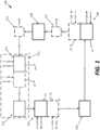
- FIG. 1is a schematic diagram of an exemplary reactor system 100.
- Reactor system 100is configured to move solid particles in a loop through a plurality of reactor assemblies, where the solid particles chemically, physically, and/or chemically and physically react with feedstock (e.g., gaseous, liquid and/or solid feedstocks) received by reactors in the reactor system and produce products that are discharged by reactors in the reactor system.
- feedstocke.g., gaseous, liquid and/or solid feedstocks
- Reactor system 100enables operating adjacent reactor assemblies at different pressures, and receiving feedstock streams and/or discharging product streams at those same pressures without the use of high energy consumption compressor units to increase the pressure of feedstock streams received by the reactor system or product streams discharged by those reactor assemblies.
- Reactor system 100may include at least a first reactor assembly 102, a first pressure transition assembly 104, a second reactor assembly 106, and second pressure transition assembly 108.
- Reactor system 100optionally may include other components, including, but not limited to a gas-solids separation unit 110, and/or one or more (up to z) pairs 112 of additional reactor assemblies and pressure transition assemblies (e.g., a third reactor assembly 113 and third pressure transition assembly 114).
- the first reactor assembly 102may comprise one or more first reactor assembly reactors, each configured to operate at a pressure P1, where the first reactor assembly is configured to receive first solid particles at the pressure P1, convert the first solid particles at the pressure P1 to second solid particles at the pressure P1, and discharge the second solid particles at the pressure P1.
- the first reactor assembly 102may include a first reactor assembly reactor 116 and optionally w number of additional first reactor assembly reactors 118, each configured to operate at a pressure P1.
- the first reactor assembly 102may receive first solid particles at the pressure P1 120, whereupon the first solid particles at the pressure P1 may be converted by the first reactor assembly reactor 116 and optionally the w number of first reactor assembly reactors 118 to second solid particles at the pressure P1 122, which are discharged from the first reactor assembly 102.
- each reactor in the first reactor assembly 102includes a solids inlet configured to receive solid particles and a solids outlet configured to discharge solid particle from the reactor.
- each reactor in the first reactor assembly 102independently may include a reactor feedstock inlet configured to receive feedstock 124, and/or a reactor product outlet configured to discharge product 126.
- Feedstock received by a reactor in the first reactor assemblymay chemically and/or physically react with solid particles within that reactor to convert the particles to particles having alternative chemical or physical compositions and/or to form a product that may be discharged from the reactor through a reactor product outlet.
- a net result of the various chemical and/or physical reactions between feedstock 124 and solid particles within the first reactor assembly reactors 116 and 118is to convert the first particles at the pressure P1 120 to the second particles at the pressure P2 122.
- the first pressure transition assembly 104is in fluid communication with the first reactor assembly 102 and the second reactor assembly 106, and is configured to receive the second solid particles at the pressure P1 122, transition the pressure surrounding the second solid particles from the pressure P1 to a pressure P2 that is different from the pressure P1, and discharge the second solid particles at the pressure P2 128.
- the pressure P2is different from the pressure P1. For example, in some embodiments, the pressure P2 is less than pressure P1.
- the second reactor assembly 106may comprise one or more second reactor assembly reactors, each configured to operate at the pressure P2, where the second reactor assembly is configured to receive the second solid particles at the pressure P2 128, convert the second solid particles at the pressure P2 to third solid particles at the pressure P2, and discharge the second third particles at the pressure P2 130.
- the second reactor assembly 106may include a second reactor assembly reactor 132 and optionally x number of additional second reactor assembly reactors 134, each configured to operate at a pressure P2.
- the second reactor assembly 106may receive second solid particles at the pressure P2 128, whereupon the second solid particles at the pressure P2 may be converted by the second reactor assembly reactor 132 and optionally the x number of second reactor assembly reactors 134 to third solid particles at the pressure P2 130, which are discharged from the second reactor assembly 106.
- each reactor in the second reactor assembly 106includes a solids inlet configured to receive solid particles and a solids outlet configured to discharge solid particle from the reactor.
- each reactor in the second reactor assembly 106independently may include a reactor feedstock inlet configured to receive feedstock 136, and/or a reactor product outlet configured to discharge product 138.
- Feedstock received by a reactor in the second reactor assemblymay chemically and/or physically react with solid particles within that reactor to convert the particles to particles having alternative chemical or physical compositions and/or to form a product that may be discharged from the reactor through a reactor product outlet.
- a net result of the various chemical and/or physical reactions between feedstock 136 and solid particles within the second reactor assembly reactors 132 and 134is to convert the second particles at the pressure P2 128 to the third particles at the pressure P2 130.
- the second pressure transition assembly 108is in fluid communication with the first reactor assembly 102 and the second reactor assembly 106, and is configured to receive the third solid particles at the pressure P2 130, transition the pressure surrounding the third solid particles from the pressure P2 to a pressure P3 that is different from the pressure P2, and discharge the third solid particles at the pressure P3 140.
- the pressure P3is the same as the pressure P1, such that the second pressure transition assembly 108 is configured to transition the pressure surrounding the third solid particles from the pressure P2 to the pressure P1 and discharge the third solid particles at the pressure P1 from the second pressure transition assembly, and wherein the third solid particles at the pressure P1 are the first solid particles at the pressure P1 received by the first reactor assembly.
- the reactor system 100may not include any reactor assembly 112 or pressure transition assembly 114 (i.e., n may be equal to 0).
- the reactor system 100optionally may include a gas-solids separation unit 110 between and in fluid communication with the second reactor assembly 106 and the first reactor assembly 102.
- the gas-solids separation unit 110may include a separation unit solids inlet configured to receive the third solid particles at either the pressure P2 130 or the pressure P3 140, a separation unit gas outlet configured to discharge gas surrounding the third particles from the gas-solids separation unit 144, and a separation unit solids outlet configured to discharge the third particles at either the pressure P2 130 or the pressure P3 140, respectively, from the gas-solids separation unit.
- the reactor system 100optionally may include one or more (up to z) pairs 112 of additional reactor assemblies and pressure transition assemblies.
- the n pairsare configured to receive the third particles at the pressure P3 140, and discharge the first particles at the pressure P1 120.
- the z pairs of additional reactor assembliescollectively function to chemically and/or physically convert the third particles to the first particles
- the n number of pressure transition assembliescollectively function to transition the pressure surrounding the particles from the pressure P3 to the pressure P1.
- the reactor system 100may include a third reactor assembly 113, which comprises one or more third reactor assembly reactors, each configured to operate at the pressure P3, wherein the third reactor assembly is configured to receive the third solid particles at the pressure P3, convert the third solid particles at the pressure P3 to the first solid particles at the pressure P3, and discharge the first solid particles at the pressure P3.
- third reactor assembly 113may include a third reactor assembly reactor 150 and optionally y number of additional third reactor assembly reactors 152, each configured to operate at the pressure P3.
- the third reactor assembly 113may receive the third solid particles at the pressure P3 140, whereupon the third solid particles at the pressure P3 may be converted by the third reactor assembly reactor 150 and optionally the y number of third reactor assembly reactors 152 to the first solid particles at the pressure P3 154, which are discharged from the third reactor assembly 113.
- each reactor in the third reactor assembly 113includes a solids inlet configured to receive solid particles and a solids outlet configured to discharge solid particle from the reactor.
- each reactor in the third reactor assembly 113independently may include a reactor feedstock inlet configured to receive feedstock 156, and/or a reactor product outlet configured to discharge product 158.
- Feedstock received by a reactor in the third reactor assemblymay chemically and/or physically react with solid particles within that reactor to convert the particles to particles having alternative chemical or physical compositions and/or to form a product that may be discharged from the reactor through a reactor product outlet.
- a net result of the various chemical and/or physical reactions between feedstock 156 and solid particles within the third reactor assembly reactors 150 and 152is to convert the third particles at the pressure P3 140 to the first particles at the pressure P3 154.
- the third pressure transition assembly 114is in fluid communication with the third reactor assembly 113 and the first reactor assembly 102, and is configured to receive the first solid particles at the pressure P3 154, transition the pressure surrounding the first solid particles from the pressure P3 to the pressure P1, and discharge the first solid particles at the pressure P1 120.
- the z pairs 112 of additional reactor assemblies and pressure transition assembliesmay include any desired number n of pairs 112.
- Each pairmay function to chemically and/or physically convert the particles received by the pair to particles having alternative chemical and/or physical compositions that are subsequently discharged by the pair.
- Each pairalso functions to transition the pressure surrounding the particles from one pressure to another.
- each of the various pressure transition assemblies 104, 108, and 114may be configured to either discharge solid particles at a constant and continuous flow rate or in batches during steady state operation.
- FIG. 2is a schematic diagram of an exemplary pressure transition assembly system 200 that may be used for any or all of pressure transition assemblies 104, 108 and 114.
- Pressure transition assembly 200is configured to receive solid particles at a first pressure P m 201, transition the pressure surrounding the particles to a second different pressure P n , and discharge the particles at the second pressure P n 215.
- Each pressure transition assemblyincludes at least a first assembly 202 comprising a first nonmechanical valve 204, a first mechanical valve 206, a second nonmechanical valve 208, and a second mechanical valve 210, wherein the first nonmechanical valve 204 is positioned between and in fluid communication with the upstream reactor assembly (not shown) and the first mechanical valve 206, the first mechanical valve 206 is operable in an open and a closed position, the second nonmechanical valve 208 is positioned between and in fluid communication with the first mechanical valve 206 and the second mechanical valve 210, and the second mechanical valve 210 is operable in an open and closed position, and wherein the second nonmechanical valve 208 further includes a second nonmechanical valve gas inlet 216 for receiving pressurized inert gas 207, where the inlet 216 is operable in an open and closed position, and a second nonmechanical valve gas outlet 218 for releasing pressurized gas 209, where the outlet 218 is operable in an open and closed position.
- Each assembly 202optionally may include at least one additional nonmechanical valve in fluid communication with and positioned between: (a) the upstream reactor assembly and the first nonmechanical valve, (b) the first nonmechanical valve and the first mechanical valve, (c) the first mechanical valve and the second nonmechanical valve, the second nonmechanical valve and the second mechanical valve, and the second mechanical valve and the downstream reactor assembly.
- at least one additional nonmechanical valvein fluid communication with and positioned between: (a) the upstream reactor assembly and the first nonmechanical valve, (b) the first nonmechanical valve and the first mechanical valve, (c) the first mechanical valve and the second nonmechanical valve, the second nonmechanical valve and the second mechanical valve, and the second mechanical valve and the downstream reactor assembly.
- the first nonmechanical assembly 202optionally may include a plurality m of first nonmechanical valves 204 in series, a plurality n of second nonmechanical valves 208 in series, a third nonmechanical valve 212 positioned between and in fluid communication with the second mechanical valve 210 and a downstream reactor assembly (not shown), or a plurality o of third nonmechanical valves 212 in series.
- pressure transition assembly 200may include a plurality m of assemblies 202 in series. In some embodiments, pressure transition assembly 200 also may include a plurality of assemblies 202 in parallel, where each of the plurality of assemblies 202 may be configured the same or differently from each other.
- each nonmechanical valve in the pressure transition assemblyis similarly sized.
- the flow rate of solid particles through the nonmechanical valvesis similar.
- a nonmechanical valvesuch as nonmechanical valve 204, 208 and/or 212, is an assembly that includes a solids inlet for receiving solid particles, a solids outlet for discharging solid particles, various conduits, at least one retaining portion, and one or more inlets for receiving flow gases, where the assembly enables selective control of the flow of solids through the nonmechanical valve.
- Exemplary nonmechanical valvesare shown in FIGS. 3-8 and are described in more detail below.
- the mechanical valves 206 and 210are selectively actuatable valves that can be actuated between an open position and a closed position.
- the mechanical valvesmay be operated manually or using a controller .
- Mechanical valvesare well known in the art, and include such valves as solenoid valves, air or electricity actuated control valves, ball valves, gate valves, butterfly valves, check valves, and the like. The particular type of mechanical valve may be selected based on its tolerance to the operating conditions of the reactor system.
- Each pressure transition assembly of the present disclosuremay comprise one or more flow gas inlets, each configured to provide a flow gas to move particles within the transition assemblies through various portions of the transition assemblies.
- Flow gases for moving particles through reactor systemsare well known in the art, and include, for example, aeration gases and lubrication gases for moving particles through the reactor system.
- Flow gasesalso may include purge gases for purging particles from nonmechanical as well as mechanical valves. Purging gases are particularly important for purging particles from mechanical valves so as to prevent the particles for damaging the mechanical valves when they are actuated between open and closed positions.
- Flow gasesmay include, but are not limited to, inert gases that do not react with the particles in the reactor system, such as nitrogen, or in some embodiments steam.
- Flow gasesmay be introduced into the pressure transition assembly through flow gas inlets that, for example, may be controlled with flow gas inlet valves that may be selectively actuated, such as with a control assembly.
- Flow gas inletsmay be provided at one or more locations in nonmechanical valves and conduits between nonmechanical valves. Flow gas inlets are shown in FIGS. 3-8 and are described in more detail below.
- the source of flow gasesmay be storage tanks containing the inert gas, where the pressure of the inert gas passing through the flow gas inlet is regulated by a regulator.
- nonmechanical valve 208receives solid particles from nonmechanical valve 204 via valve 206.
- Nonmechanical valve 208also includes a gas inlet 216 configured to receive pressurized inert gas 207, where the gas inlet 216 is operable in an open position and in a closed position.
- Nonmechanical valve 208also includes gas outlet 218 configured to release pressurized gas 209, where the gas outlet 218 is operable in an open position and a closed position.
- Pressure transition assembly 202includes various operational modes.
- a first modethe pressure within nonmechanical valve 204 and nonmechanical valve 208 is P m .
- a first plurality of solid particles at the pressure P mare received by the nonmechanical valve 204 in a manner that prevents the first plurality of the solid particles at the pressure P m from coming into direct contact with the valve 206.
- Nonmechanical valve 204is configured to discharge (e.g., with the use of flow gases) the first plurality of the solid particles at the pressure P m through the valve 206 and into nonmechanical valve 208, where nonmechanical valve 208 subsequently receives the first plurality of the solid particles at the pressure P m in a manner that prevents the first plurality of the solid particles at the pressure P m from directly contacting the mechanical valve 206 or the mechanical valve 208.
- the mechanical valve 206 and mechanical valve 210are in the closed position, and either the nonmechanical valve gas inlet 216 is in the closed position and the nonmechanical valve gas outlet 218 is in the open position, or the nonmechanical valve gas inlet 216 is in the open position and the nonmechanical valve gas outlet 218 is in the closed position.
- the pressure transition assemblyis being used to increase the pressure surrounding the first plurality of solid particles (i.e., if P n is greater than P m )
- the nonmechanical valve gas inlet 216is in the open position and the nonmechanical valve gas outlet 218 is in the closed position.
- the pressure transition assemblyis being used to decrease the pressure surrounding the first plurality of solid particles (i.e., if P m is greater than P n )
- the nonmechanical valve gas inlet 216is in the closed position and the nonmechanical valve gas outlet 218 is in the open position.
- the pressure surrounding the first plurality of solid particles in nonmechanical valve 208is transitioned from the pressure P n to the pressure P m .
- nonmechanical valve 208is configured to discharge the first plurality of solid particles at the pressure P n from nonmechanical valve 208 and through valve 210. These particles are either discharged from the pressure transition assembly in a batch as solid particles at pressure P n 215, or they are received by optional nonmechanical valve 212.
- mechanical valve 206 and mechanical valve 210are each in the closed position, and either nonmechanical valve gas inlet 216 is in the open position, and nonmechanical valve gas outlet 218 is in the closed position, or nonmechanical valve gas inlet 216 is in the closed position, and nonmechanical valve gas outlet 218 is in the open position.
- the configuration of the inlet and outlet in the fifth modewill be opposite from the configuration used in the third mode so as to transition the pressure within the second nonmechanical valve from the pressure P n back to the pressure P m so as to prepare the nonmechanical valve 208 to receive the next batch of particles at the pressure P m .
- At least one pressure transition assemblywill cause the pressure surrounding the particles moving through the pressure transition assembly to decrease, and at least one other pressure transition assembly will cause the pressure surrounding the particles moving through the pressure transition assembly to increase.
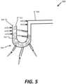
- FIGS. 3-8are schematic depictions of exemplary nonmechanical valves usable in reactor system 100 and pressure transition assembly system 200.
- Each nonmechanical valve 300 shown in FIGS. 3-8includes a solids inlet 304 for receiving solid particles, a retaining portion 306, and solids outlet 308 for discharging solid particles.
- Solid particles 302are shown schematically in the nonmechanical valves and arrows 312 show, generally, the flow of solid particles 302 through the nonmechanical valves.
- Example nonmechanical valves 300include, but are not limited to, devices such as L-valves, J-valves, Loop seal valves, reversed V-valves, H-valves, or the like where inert gas is provided to aid solids flow.
- Each nonmechanical valvealso includes one or more inert gas inlets 310 configured to receive inert gas 314 and operable in an open and closed position.
- Inert gas 314can be used as a flow gas and/or lubrication gas to aid in solid particles 302 flow through the nonmechanical valves.
- Example inert gasesinclude N 2 , CO 2 , He, and the like (depending on the type of particles flowing through the reactor system).
- Each nonmechanical valveis configured such that the valve retains a plurality of particles in the retaining portion in a manner that prevents the particles from directly contacting upstream and/or downstream mechanical valves when those mechanical valves are in the closed position.
- This configurationis critical for preventing the high temperature solid particles 302 from coming into contact with the mechanical valves, which rapidly deteriorate when exposed to high temperature particles for extended periods of time.
- FIG. 9shows example method 400 for operating a reactor system. Reactor systems described and contemplated herein can be utilized to perform the operations of method 400.
- Method 400begins by providing first solid particles at a pressure P1 to a first reactor assembly (operation 402).
- the first reactor assemblyis operated at pressure P1 (operation 406).
- the first reactor assemblyincludes one or more first reactor assembly reactors each configured to operate at the pressure P1.
- first solid particles at the pressure P1are converted to second solid particles at the pressure P1 (operation 410).
- a first reactor feedstockis provided to a first reactor in the first reactor assembly.
- the first reactor feedstockchemically and/or physically reacts with the first solid particles to form the second solid particles at the pressure P1 and a first reactor product.
- the first reactor productis discharged from the first reactor.
- the second solid particles at the pressure P1are provided to a first pressure transition assembly (operation 414).
- the first pressure transition assemblytransitions the pressure surrounding the second solid particles from the pressure P1 to a pressure P2 (operation 418).
- Pressure P2is different from the pressure P1.
- the second solid particles at the pressure P2are discharged from the first pressure transition assembly and provided to a second reactor assembly (operation 422).
- the second reactor assemblyis operated at the pressure P2 (operation 426).
- the second reactor assemblyincludes one or more second reactor assembly reactors each configured to operate at the pressure P2.
- the second solid particles at the pressure P2are converted to third solid particles at the pressure P2 (operation 430).
- a second reactor feedstockis provided to a second reactor in the second reactor assembly.
- the second reactor feedstockchemically and/or physically reacts with the second solid particles to form the third solid particles at the pressure P2 and, in some instances, a second reactor product.
- the second reactor productis discharged from the second reactor.
- the third solid particles at the pressure P2are provided to a second pressure transition assembly (operation 434).
- the second pressure transition assemblytransitions the pressure surrounding the third solid particles from the pressure P2 to a pressure P3 (operation 438). Pressure P3 is different from the pressure P2. Then the third solid particles at the pressure P3 are discharged from the second pressure transition assembly (operation 442).
- the pressure P3is the same as the pressure P1.
- operation 438includes transitioning the pressure surrounding the third solid particles from the pressure P2 to the pressure P1.
- Operation 442then further includes discharging third solid particles at the pressure P1 and providing those particles to the first reactor assembly.
- the third solid particles at either the pressure P2 or the pressure P3are provided to a gas-solids separation unit in fluid communication with the second reactor assembly and the first reactor assembly. Then, gas surrounding the third solid particles is discharged from the gas-solids separation unit. Additionally, the third solid particles at either the pressure P2 or the pressure P3 is discharged from the gas-solids separation unit.
- method 400includes providing the third solid particles at the pressure P3 to a third reactor assembly.
- method 400includes operating the third reactor assembly at the pressure P3, where the third reactor assembly includes one or more third reactor assembly reactors each configured to operate at the pressure P3.
- Feedstock received by a reactor in the third reactor assemblymay chemically and/or physically react with solid particles within that reactor to convert the particles to particles having alternative chemical or physical compositions and/or to form a product that may be discharged from the reactor through a reactor product outlet. That is, the third reactor assembly converts the third solid particles at pressure P3 to first solid particles at pressure P3.
- a third reactor assemblyprovides solid particles at the pressure P3 to a third pressure transition assembly.
- the third pressure transition assemblyis in communication with the third reactor assembly and the first reactor assembly.
- the third pressure transition assemblytransitions the pressure surrounding the first solid particles from the pressure P3 to the pressure P1. Then, the third pressure transition assembly discharges the first solid particles at the pressure P1.
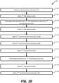
- FIG. 10shows example method 418 for operating a first pressure transition assembly during example method 400.
- Pressure transition assemblies described and contemplated herein, with particular reference to FIG. 2 and corresponding discussion above,can be utilized to perform the operations of method 418.
- the discussion belowreferences various components described above with reference to FIG. 2 .
- example method 418includes operations for transitioning a pressure surrounding solid particles in a pressure transition assembly.
- example method 418is used to lower pressure surrounding solid particles from a pressure P1 to a pressure P2.
- Method 418begins by receiving second solid particles at pressure P1 (operation 502).
- the first mechanical valveis in the closed position and the pressure within the first nonmechanical valve is P1.
- Receiving solid particles at pressure P1 (operation 502)is performed in a manner that prevents the solid particles at the pressure P1 from coming into direct contact with the first mechanical valve when the first mechanical valve is in the closed position.
- the first mechanical valveis opened (operation 504). Opening the first mechanical valve occurs when the pressure within the first nonmechanical valve is P1, the second mechanical valve is in the closed position, the second nonmechanical valve gas inlet is in the closed position and the second nonmechanical valve gas outlet is in the closed position.
- Operation 510can also include monitoring a pressure within the second nonmechanical valve.
- the second nonmechanical valve gas outletis closed (operation 512).
- the second mechanical valveis opened (operation 514) and the solid particles at pressure P2 are discharged from the second nonmechanical valve (operation 516).
- the second mechanical valveis closed (operation 518). Then the pressure within the second nonmechanical valve is transitioned from the pressure P2 to the pressure P1 by opening the nonmechanical valve gas inlet (operation 520).
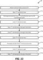
- FIG. 11shows example method 438 for operating a second pressure transition assembly during example method 400.
- Pressure transition assemblies described and contemplated herein, with particular reference to FIG. 2 and corresponding discussion above,can be utilized to perform the operations of method 438.
- the discussion belowreferences various components described above with reference to FIG. 2 .
- example method 438includes operations for transitioning a pressure surrounding solid particles in a pressure transition assembly.
- Example method 438can be used to raise or lower a pressure surrounding solid particles from a pressure P2 to a pressure P3.
- Method 438begins by receiving second solid particles at pressure P2 (operation 550).
- the third mechanical valveis in the closed position and the pressure within the third nonmechanical valve is P2.
- Receiving third solid particles at pressure P2 (operation 550)is performed in a manner that prevents the third solid particles at the pressure P2 from coming into direct contact with the third mechanical valve when the third mechanical valve is in the closed position.
- the third mechanical valveis opened (operation 552). Opening the third mechanical valve occurs when the pressure within the third nonmechanical valve is P2, the fourth mechanical valve is in the closed position, the fourth nonmechanical valve gas inlet is in the closed position and the fourth nonmechanical valve gas outlet is in the closed position.
- Pressureis transitioned by opening the fourth nonmechanical valve gas outlet or inlet (operation 558). That is, to increase the pressure in the fourth nonmechanical valve, the fourth nonmechanical valve gas inlet is opened. Conversely, to decrease the pressure in the fourth nonmechanical valve, the fourth nonmechanical valve gas outlet is opened. Operation 558 can also include monitoring a pressure within the fourth nonmechanical valve.
- the fourth mechanical valveis closed (operation 566). Then the pressure within the fourth nonmechanical valve is transitioned from the pressure P3 to the pressure P2 by opening either the nonmechanical valve gas inlet or outlet (operation 568), depending upon which was opened and closed during operations 558 and 560.
- systems and methods described abovecan be applied to a variety of reactor system types, solid particle types, and operating conditions.
- systems and methods disclosed hereinfind application in chemical looping reactor systems, in product purification systems, and in reactive adsorption systems.
- Example configurations and applications of the systems and methods described aboveare provided below.
- Example flow schemes for the solid particles and gaseous components in one or more reactor assemblies in the reactor systeminclude: countercurrent or co-current moving bed, fluidized bed in any fluidization regimes, countercurrent or co-current fixed bed, and any combination of these reactors.
- Chemical looping reactor systemstypically include systems that perform reduction-oxidation and/or reaction-regeneration using catalytic or non-catalytic metal derivative materials such as metal-oxides, metal-carbides, metal-nitrides, metal-borides and metal-silicides.
- the first reactor assembly, the second reactor assembly, and the third reactor assemblycan include one or more of: reducer reactors, oxidizer reactors, and combustion reactors.
- Chemical looping reactor systemshave a wide range of energy applications including power generation, chemical synthesis, liquid fuel production, CO 2 utilization and solar energy conversion.
- Chemical looping reactor systemsutilize two reactor types to perform these reaction functions: the reducer/reactor and the combustor/regenerator. The separation of the reducer/reactor and the combustor/regenerator allows for increasingly pure product gas generation.
- each of these reactorscan be demonstrated using metal-oxides as example catalytic metal derivatives in a chemical looping system and methane as an example energy source.
- a chemical looping reducer reactoroxidizes methane to produce either partial (CO + H 2 ) or full (CO 2 + H 2 O) combustion products, depending on the metal-oxide and the desired downstream product.
- the methane oxidationoccurs utilizing the oxygen from the metal-oxide, which is reduced to a lower oxidation state.
- the oxygen-depleted metal-oxideis regenerated in the combustor reactor using air as the oxygen source.
- a third reactoris included between the reducer and the combustor reactor.
- the oxidizerpartially oxidizes the reduced metal-oxide from the reducer reactor using steam and/or CO 2 to produce H 2 and/or CO. This partially oxidized metal-oxide is re-oxidized using air in the combustor reactor.
- Product purificationincludes processes such as nitrogen production from air, CO 2 removal from hydrogen prior to use in ammonia production, removal of H 2 S from hydrogen in hydrotreating and hydrocracking units and CO 2 removal from biogas to increase methane content.
- the technology used in these processesis also known as the Pressure Swing Adsorption technology (PSA) and generally employs two or more reactors operated under different pressures for continuous operation.
- PSAPressure Swing Adsorption technology
- one reactoris operated at a higher pressure to enhance the adsorption of the desired gas whereas the other reactor is operated at a lower pressure to regenerate the adsorbent and recover the adsorbed gas.
- the process scheme selectedthere can be intermediate steps of delivery, purge and backfill in a pressure swing adsorption cycle.
- Reactive adsorption processesalso known as sorption enhanced recovery process (SERP) conducts reactions along with product separation in a single reactor.
- the reactorcontains a mixture of catalyst and adsorbent material which are homogeneously mixed.
- the reactantsare injected at a high pressure into the reactor where they are converted to products by the catalyst.
- the adsorbentadsorbs the products generated and shifts the reaction equilibrium towards forming more products which increases the reactant conversion and also the product purity.
- the adsorbed productsare then desorbed from the adsorbent at a lower pressure in the regenerator.
- the reactor and the regeneratorcan be operated in a fixed bed, moving bed or fluidized bed reactor configuration. The following are some example implementations.
- the above described systemscan be used for pure nitrogen production.
- the systemis operated with a plurality of particles comprising adsorbents like zeolite 5A, zeolite 13X and Carbon molecular sieves with a particle diameter ranging from 2 mm to 5 mm.
- adsorbentslike zeolite 5A, zeolite 13X and Carbon molecular sieves with a particle diameter ranging from 2 mm to 5 mm.
- one of the reactorsis operated under elevated pressure (e.g., 8 bara) for the adsorption of oxygen by adsorbent particles and thus pure nitrogen is obtained at the reactor outlet.
- the other reactoris operated at a lower pressure (e.g., 1 bara) for the desorption of oxygen from adsorbent particles.
- Both the reactorsare operated at temperature ranges between 35-40°C.
- the above described systemscan be used for CO x removal from hydrogen.
- Hydrogen produced from steam methane reformingcontains impurities of CO and CO 2 (CO x ) which need to be removed before the hydrogen being used for downstream processes.
- the systemis operated with a plurality of particles comprising adsorbents like zeolite 5A, activated carbon and zeolite 13X.
- one of the reactorsis operated under elevated pressure (e.g., 7 bara) for the adsorption of CO x impurities by adsorbent particles and thus hydrogen stream with a purity of 99.999% is obtained at the reactor outlet.
- the other reactoris operated at a lower pressure (e.g., 0.1 bara) for the desorption of CO x from adsorbent particles.
- Both the reactorsare operated at temperature ranges between 30-35°C.
- the above described systemcan be used for H 2 S removal from process gases.
- H 2 Sis removed from process gases and/or vent gases in oil refineries, coal gasification units and geothermal plants.
- the systemis operated with a plurality of particles comprising adsorbents like silicalite and alumina.
- one of the reactorsis operated under elevated pressure (e.g., 1.05-1.5 bara) for the adsorption of H2s from process gases by adsorbent particles.
- the other reactoris operated at a lower pressure (e.g., 0.05 - 0.3 bara) for the desorption of H 2 S from adsorbent particles.
- Both the reactorsare operated at temperature ranges between 10-50°C.
- Biogascontains about 30-40% CO 2 .
- the CO 2is removed from biogas using the system operated with a plurality of particles comprising adsorbents like molecular sieves, activated carbons, zeolites and titanosilicates.
- one of the reactorsis operated under elevated pressure (e.g., 4-10 bara) for the adsorption of CO 2 by adsorbent particles.
- the other reactoris operated at a lower pressure (e.g., 0.1 - 0.3 bara) for the desorption of CO 2 from adsorbent particles. Both the reactors are operated at temperature ranges between 25-50°C.
- the above described systemcan be used for reverse water gas shift reaction for the production of CO from CO 2 and H 2 .
- the systemis operated with a plurality of particles comprising a low-temperature shift catalyst and NaX zeolite adsorbent.
- one reactoris operated under elevated pressure (e.g. 4.8 bara) and temperature of about 250 °C for the generation of CO with a purity of >99% from CO2 and H2. is an equilibrium controlled reaction which can be carried out at 480 kPa and 250°C in presence of a low-temperature shift catalyst and NaX zeolite adsorbent.
- the other reactoris operated at a lower pressure, (e.g. 1.15 - 1.29 bara) for the regeneration of particles.
- the above described systemcan be used for butadiene production from 1-butene through dehydrogenation reactions.
- the systemis operated with a plurality of particles comprising a CrO 2 -alumina catalyst mixed with zeolite K-Y adsorbent.
- one reactoris operated under elevated pressure (e.g., 1.2 -2.5 bara) and temperature (e.g., 250 - 500 °C) for the generation of 1,3-butadience which is subsequently adsorbed in by the zeolite adsorbent.
- the adsorbed 1,3-butadieneis then desorbed from the adsorbent particles in the other reactor operated at a lower pressure (e.g., 1 bara), and the pure stream of 1,3-butadiene is produced.
- the systemcan also be used to produce benzene from cyclohexane and/or toluene from methyl-cyclohexane.
- the above described systemcan be used for isomerization of n-paraffins to isoparaffins for upgrading naphtha.
- the systemis operated with a plurality of particles comprising a Pd/H-faujasite catalyst and zeolite adsorbent.
- one reactoris operated under elevated pressure (e.g., 14 -20 bara) and temperature (e.g., 200 - 400 °C) for the generation of iso-pentane by partially converting n-pentane and the unconverted n-pentane is adsorbed in the zeolite adsorbent bed.
- the above described systemcan be used for hydrogen production from steam methane reforming.
- the systemis operated with a plurality of particles comprising a Ni-based catalyst and hydrotalcite-based CO 2 adsorbent.
- one reactoris operated under elevated pressure (e.g., 5 bara) and temperature (e.g., 450 °C) for the generation of hydrogen.
- the CO 2 generated during the reactoris adsorbed by the sorbent.
- the adsorbed CO 2is then desorbed from the adsorbent particles in the other reactor operated at a lower pressure (e.g., 1 bara) and at the same time, the particles are regenerated.
- reactorsoperating at different pressures.
- one or more compressor unitswere needed to compress reactor input streams and/or reactor outlet or product streams.
- an example co-current chemical looping systemoperates a reducer reactor and a combustor reactor at comparable pressure.
- Such a chemical looping system operating at comparable pressuresrequires the use of compressors and expanders when the desired downstream product is at higher pressures.
- the coal-direct chemical looping system for generating electricity from coaloperates at atmospheric pressure but requires a compressor to pressurize the CO 2 produced to 150 atm for sequestration.
- the energy penalty for this coal-direct chemical looping system with 90% CO 2 captureis 10% as compared to a baseline pulverized coal plant without CO 2 capture. Around half of this energy penalty ( ⁇ 5%) comes from CO 2 compression, the capital cost of which is -80% of the reducer reactor.
- a higher pressure operation of a coal direct chemical looping (CDCL) system following the chemical looping systemnecessitates the use of an air compressor to compress air for regeneration (i.e., reoxidation) of the redox active catalytic particles.
- CDCLcoal direct chemical looping
- the methane to syngas (MTS) chemical looping systemwhen integrated into a gas to liquids plant, is required to provide syngas at 30 atm for the Fischer-Tropsch reactors.
- MTS syngas generation technologyin a 50,000 bbl/day gas to liquids plant shows that 40% to 70% of the capital cost comes from the compression demands.
- the compression costsplay a significant role in determining the overall economics and energy efficiency.
- the instantly disclosed systems and methodsenable operating reactor assemblies at different pressures without the use of compressors for reactor input streams and/or reactor outlet or product streams.
- piping around valves and the valve body itselfcan be forcibly cooled.
- the heat exchange strategies and the cooling methodscan include, but are not limited to, gas cooling, liquid cooling, a combination of them, or the like.
- cooling portsare added to the pipes before and after the valve to allow cooling gas flow through the pipe.
- the working environment of the valveis kept cool.
- a heat exchangeris installed along a pipe section before and after the valve and heat is removed through the coolant flowing through the heat exchanger.
- An inert gas inletcan be added upstream of the valve to remove the debris from the valve area before closing the valve.
- inert gasis directed through the pipe at the valve area to move debris near the valve.
- a drainage pipecan be added to the pipe immediately after the valve, serving as the outlet of the inert gas.
- one reactor in the system or methodoperates at a pressure of about 2 atm to about 150 atm, or about 5 atm to about 150 atm, or about 10 atm to about 150 atm, e.g., about 2 atm, about 3 atm, about 4 atm, about 5 atm, about 6 atm, about 7 atm, about 8 atm, about 9 atm, about 10 atm, about 15 atm, about 20 atm, about 25 atm, about 30 atm, about 35 atm, about 40 atm, about 45 atm, about 50 atm, about 55 atm, about 60 atm, about 65 atm, about 70 atm, about 75 atm, about 80 atm, about 85 atm, about 90 atm, about 95 atm, about 100 atm, about 105 atm, about 110 atm, about 115 atm, about 120 atm, about 125 atm
- another reactor in the system or methode.g., the second reactor of a two-reactor system or method or the third reactor of a three-reactor system or method
- this reactorcan operate at ambient pressure.
- this reactorcan operate at a pressure that about 1 atm less, about 2 atm less, about 3 atm less, about 4 atm less, about 5 atm less, about 6 atm less, about 7 atm less, about 8 atm less, about 9 atm less, about 10 atm less, about 15 atm less, about 20 atm less, about 25 atm less, about 30 atm less, about 35 atm less, about 40 atm less, about 45 atm less, about 50 atm less, about 55 atm less, about 60 atm less, about 65 atm less, about 70 atm less, about 75 atm less, about 80 atm less, about 85 atm less, about 90 atm less, about 95 atm less, about 100 atm less, about 105 atm less, about 110 atm less, about 115 atm less, about 120 atm less, about 125 atm less, about 130 atm less, about 135atm less, about 140 atm less, or about 145atm less, compared to the higher-pressure reactor(s) of the
- particlesparticles
- solids particlesparticles
- metal oxide particlesmay be used interchangeably herein.
- the systems and methods described hereinuse a plurality of particles to chemically or physically react with feedstock.
- the particlesmay comprise a metal oxide to oxidize fuel, where the metal is selected from Fe, Co, Ni, Cu, Mo, Mn, Sn, Ru, and Rh, or any combination thereof.
- the metal oxidecomprises Fe 2 O 3 or a composite metal oxide such as FeO•TiO 2 or FeO•Al 2 O 3 .
- the metal oxidecycles through multiple oxidation states.
- the metal oxidemay cycle through oxidation states including a reduced metal (e.g., Fe), a reduced metal oxide (e.g., FeO), and an intermediate oxidation state metal oxide (e.g., Fe 3 O 4 ).
- the particlesmay be adsorbents made with very porous materials for their large specific surface areas. Typical adsorbents include but are not limited to activated carbon, silica gel, alumina, resin and zeolite.
- the particlesmay include one or more support materials.
- the one or more support materialscan be selected from metals, metal oxides, metal carbides, metal nitrates, and metal halides, wherein the metal is selected from Li, Be, B, Na, Mg, Al, Si, K, Ca, Sc, Ti, V, Cr, Mn, Co, Zn, Ga, Ge, Rb, Sr, Y, Zr, Nb, Mo, Cd, In, Sn, Sb, Cs, Ba, La, Ce, and Th.
- the one or more support materialsare selected from alumina, ceria, niobia, silica, tantalum oxide, tin oxide, and titania, or any combination thereof.
- the plurality of particlesmay further comprise a dopant, such as a dopant selected from Sc, Ti, V, Cr, Mn, Fe, Co, Ni, Cu, Zn, Y, Zr, Nb, Mo, Tc, Ru, Rh, Pd, Ag, Cd, Lu, Hf, Ta, W, Re, Os, Ir, Pt, and Au, or any combination thereof.
- the dopantmay be selected from Co, Ni, and Cu.
- the particles that may be used in the systems and methods described hereininclude particles described in International Patent Publication Nos. WO 2010/037011 , WO 2012/155059 , and WO 2014/160223 , and in U.S. Provisional Patent Application Nos. 62/519,376 (filed June 27, 2017 ) and 62/546,886 (filed August 17, 2017 ).
- a baseline US Department of Energy reportshows that the capital cost investment for a 50,000 barrel per day (bpd) gas to liquids plant is $86,000/bpd.
- a chemical looping syngas generation without the use of this inventionwas sized to yield a capital cost of the GTL plant of -$80,000/bpd.
Landscapes
- Chemical & Material Sciences (AREA)
- Chemical Kinetics & Catalysis (AREA)
- Organic Chemistry (AREA)
- Engineering & Computer Science (AREA)
- Combustion & Propulsion (AREA)
- Inorganic Chemistry (AREA)
- Health & Medical Sciences (AREA)
- General Health & Medical Sciences (AREA)
- Analytical Chemistry (AREA)
- General Chemical & Material Sciences (AREA)
- Oil, Petroleum & Natural Gas (AREA)
- Physical Or Chemical Processes And Apparatus (AREA)
Description
- The present disclosure relates to systems and methods for reactor systems involving solid particles circulating between reactor assemblies. More particularly, the present disclosure relates to reactor systems in which two or more reactors operate at unequal pressures.
- For most reaction systems, the choice of an operating pressure to produce desired product is a part of the system design. Operating pressure directly affects the system performance and economics. For example, in a methane to syngas chemical looping system, an increase in reducer reactor pressure from 1 atm to 10 atm increases the kinetics of methane conversion by a factor of '2'. However, an increase in the reducer pressure from 1 atm to 10 atm, leads to a decrease in the maximum thermodynamic equilibrium conversion of methane to syngas.
- In addition to affecting intrinsic parameters like thermodynamic equilibrium, reaction kinetics and net system heat balance, the choice of operating pressure affects the compression costs and energy consumption associated with a reactor system. For example, typical syngas supply pressure requirements are 30 atm when integrating a methane-to-syngas chemical looping system in a Fischer-Tropsch based gas-to-liquids plant. If the methane to syngas system operates at 30 atm, significant air compression energy is required for re-oxidizing the reduced metal-oxide at 30 atm in order to maintain solids circulation. Alternatively, a chemical looping system operating at 1 atm requires a syngas compressor to compress the syngas produced from 1 atm to 30 atm. At intermediate pressures between 1 atm and 30 atm, a combination of syngas compressors and air compressors are necessary for operating previously implemented chemical looping systems.
- Depending on the choice of operating pressure and the energy recovery scheme, compressors and/or expanders can cumulatively cost 40 % - 70% of the total reactor system capital cost. In another example, in a chemical looping combustion system with CO2 capture, the Ohio State coal direct chemical looping (CDCL) system had an energy penalty of 10.6% relative to a baseline supercritical plant with no CO2 capture. Around half of this energy penalty came from compressing the CO2 in the reducer reactor outlet from near atmospheric pressure to -150 atm, typical for sequestration requirements. The cost of a CO2 compressor for the CDCL application is -80% that of the CDCL reducer reactor. In general, for reactor systems designed to generate product at pressures higher than atmospheric pressure, the compression costs play a significant role in determining the overall economics and energy efficiency.
US 2014/034134 A1 discloses an apparatus with first and second reactors, with a stripping zone that forms a nonmechanical seal between them, the stripping zone adapted to prevent process gas from the first reactor passing through to the second reactor. Additional nonmechanical seals may be included between the second reactor and a third reactor.US 2016/016137 A1 discloses an apparatus with first and second reactors, which may be connected by a nonmechanical seal operable to prevent the transfer of gas from the first reactor to the second reactor.EP 2406545 A2 discloses an apparatus with first and second reactors, which may be separated by nonmechanical seals for regulation of gas and solid flow between the reactors.WO 2014/152814 A1 discloses an apparatus with first and second reactors, which are separated by nonmechanical seals for regulation of gas flow between the reactors. - The present application discloses reactor systems and methods for operating reactor systems. Specifically, the present application discloses reactor systems, comprising (a) a first reactor assembly, which comprises one or more first reactor assembly reactors, each configured to operate at a pressure P1, wherein the first reactor assembly is configured to receive first solid particles at the pressure P1, convert the first solid particles at the pressure P1 to second solid particles at the pressure P1, and discharge the second solid particles at the pressure P1, (b) a first pressure transition assembly in fluid communication with the first reactor assembly and a second reactor assembly, wherein the first pressure transition assembly is configured to receive the second solid particles at the pressure P1, transition the pressure surrounding the second solid particles from the pressure P1 to a pressure P2 that is different from the pressure P1, and discharge the second solid particles at the pressure P2, (c) the second reactor assembly, which comprises one or more second reactor assembly reactors, each configured to operate at the pressure P2, wherein the second reactor assembly is configured to receive the second solid particles at the pressure P2, convert the second solid particles at the pressure P2 to third solid particles at the pressure P2, and discharge the third solid particles at the pressure P2, and a second pressure transition assembly in fluid communication with the second reactor assembly and the first reactor assembly, the second pressure transition assembly configured to receive third solid particles at the pressure P2, transition the pressure surrounding the third solid particles from the pressure P2 to a pressure P3 that is different from the pressure P2, and discharge the third solid particles at the pressure P3 from the second pressure transition assembly.
- The first pressure transition assembly of the reactor systems of the present disclosure includes a first nonmechanical valve, a first mechanical valve, a second nonmechanical valve and a second mechanical valve. The first nonmechanical valve is positioned between and in fluid communication with the first reactor assembly and the first mechanical valve. The first mechanical valve is operable in an open and a closed position. The second nonmechanical valve is positioned between and in fluid communication with the first mechanical valve and the second mechanical valve. The second mechanical valve is operable in an open and closed position. The second nonmechanical valve further includes a gas inlet for receiving pressurized inert gas that is operable in an open and closed position, and a second nonmechanical valve gas outlet for releasing pressurized gas that is operable in an open and closed position.
- The first pressure transition assembly of the reactor systems of the present disclosure further may comprise at least one additional nonmechanical valve in fluid communication with and positioned between the first reactor assembly and the first nonmechanical valve, the first nonmechanical valve and the first mechanical valve, the first mechanical valve and the second nonmechanical valve, the second nonmechanical valve and the second mechanical valve, and the second mechanical valve and the second reactor assembly.
- The first pressure transition assembly of the reactor systems of the present disclosure may operate in (a) a first mode wherein the pressure within the first and second nonmechanical valves is P1, the first mechanical valve is in a closed position, and a first plurality of the second solid particles at the pressure P1 are received by the first nonmechanical valve in a manner that prevents the first plurality of the second solid particles at the pressure P1 from coming into direct contact with the first mechanical valve, (b) a second mode wherein the first mechanical valve is in an open position, the second mechanical valve is in a closed position, the second nonmechanical valve gas inlet is in a closed position, and the second nonmechanical valve gas outlet is in a closed position, wherein the first nonmechanical valve is configured to discharge the first plurality of the second solid particles at the pressure P1 through the first mechanical valve and into the second nonmechanical valve, wherein subsequently the second nonmechanical valve receives the first plurality of the second solid particles at the pressure P1 in a manner that prevents the first plurality of the second solid particles at the pressure P1 from directly contacting the first or second mechanical valves, (c) a third mode wherein the first and second mechanical valves are in the closed position, the second nonmechanical valve gas inlet is in the closed position, and the second nonmechanical valve gas outlet is in the open position, whereupon the pressure surrounding the first plurality of the second solid particles in the second nonmechanical valve is transitioned from the pressure P1 to the pressure P2, (d) a fourth mode, wherein the first mechanical valve is in the closed position, the second mechanical valve is in the open position, and the second nonmechanical valve gas inlet and second nonmechanical valve gas outlet are each in the closed position, whereupon the second nonmechanical valve is configured to discharge the first plurality of the second solid particles at the pressure P2 from the second nonmechanical valve and through the second mechanical valve, and (e) a fifth mode, wherein the first and second mechanical valves are each in the closed position, the second nonmechanical valve gas inlet is in the open position, and the second nonmechanical valve gas outlet is in the closed position, whereupon the pressure within the second nonmechanical valve transitions from the pressure P2 to the pressure P1.
- The second pressure transition assembly of the reactor systems of the present disclosure may include a third nonmechanical valve, a third mechanical valve, a fourth nonmechanical valve and a fourth mechanical valve. The third nonmechanical valve may be positioned between and in fluid communication with the second reactor assembly and the third mechanical valve. The third mechanical valve may be operable in an open and a closed position. The fourth nonmechanical valve may be positioned between and in fluid communication with the third mechanical valve and the fourth mechanical valve. The fourth mechanical valve may be operable in an open and closed position. The fourth nonmechanical valve further may include a fourth nonmechanical valve gas inlet for receiving pressurized inert gas that is operable in an open and closed position, and a fourth nonmechanical valve gas outlet for releasing pressurized gas that is operable in an open and closed position.
- The second pressure transition assembly of the reactor systems of the present disclosure further may comprise at least one additional nonmechanical valve in fluid communication with and positioned between the second reactor assembly and the third nonmechanical valve, the third nonmechanical valve and the third mechanical valve, the third mechanical valve and the fourth nonmechanical valve, and the fourth nonmechanical valve and the fourth mechanical valve.
- The second pressure transition assembly of the reactor systems of the present disclosure further may operate in (a) a first mode wherein the pressure within the third and fourth nonmechanical valves is P2, the third mechanical valve is in a closed position, and a first plurality of the third solid particles at the pressure P2 are received by the third nonmechanical valve in a manner that prevents the first plurality of the third solid particles at the pressure P2 from coming into direct contact with the third mechanical valve, (b) a second mode wherein the third mechanical valve is in an open position, the fourth mechanical valve is in a closed position, the fourth nonmechanical valve gas inlet is in a closed position, and the fourth nonmechanical valve gas outlet is in a closed position, wherein the third nonmechanical valve is configured to discharge the first plurality of the third solid particles at the pressure P2 through the third mechanical valve and into the fourth nonmechanical valve, wherein subsequently the fourth nonmechanical valve receives the first plurality of the third solid particles at the pressure P2 in a manner that prevents the first plurality of the third solid particles at the pressure P2 from coming into direct contact with the third or fourth mechanical valves, (c) a third mode wherein the third and fourth mechanical valves are in the closed position, and either the fourth nonmechanical valve gas outlet or the fourth nonmechanical valve gas inlet is in the open position, whereupon the pressure surrounding the first plurality of third solid particles in the fourth nonmechanical valve is transitioned from the pressure P2 to the pressure P3, (d) a fourth mode, wherein the third mechanical valve is in the closed position, the fourth mechanical valve is in the open position, and the fourth nonmechanical valve gas inlet and fourth nonmechanical valve gas outlet are each in the closed position, whereupon the fourth nonmechanical valve is configured to discharge the first plurality of the third solid particles at the pressure P3 from the fourth nonmechanical valve and through the fourth mechanical valve, and (e) a fifth mode, wherein the third and fourth mechanical valves are each in the closed position, and either the fourth nonmechanical valve gas inlet or the fourth nonmechanical valve gas outlet is in the open position, whereupon the pressure within the second nonmechanical valve transitions from the pressure P3 to the pressure P2.
- The present disclosure also provides methods for operating reactor systems. Specifically, the methods of the present disclosure comprise (a) providing first solid particles at a pressure P1 to a first reactor assembly, (b) operating the first reactor assembly at the pressure P1, the first reactor assembly including one or more first reactor assembly reactors each configured to operate at the pressure P1, (c) in the first reactor assembly, converting the first solid particles at the pressure P1 to second solid particles at the pressure P1, (d) providing the second solid particles at the pressure P1 to a first pressure transition assembly, (e) in the first pressure transition assembly, transitioning the pressure surrounding the second solid particles from the pressure P1 to a pressure P2 that is different from the pressure P1, (f) discharging the second solid particles at the pressure P2 from the first pressure transition assembly, and providing the second solid particles at the pressure P2 to a second reactor assembly, (g) operating the second reactor assembly at the pressure P2, the second reactor assembly including one or more second reactor assembly reactors each configured to operate at the pressure P2, (h) in the second reactor assembly, converting the second solid particles at the pressure P2 to third solid particles at the pressure P2, (i) providing the third solid particles at the pressure P2 to a second pressure transition assembly, (j) in the second pressure transition assembly, transitioning the pressure surrounding the third solid particles from the pressure P2 to a pressure P3 that is different from the pressure P2, and (k) discharging the third solid particles at the pressure P3 from the second pressure transition assembly.
- The first pressure transition assembly of the methods of the present disclosure include a first nonmechanical valve, a first mechanical valve, a second nonmechanical valve and a second mechanical valve, wherein the first nonmechanical valve is positioned between and in fluid communication with the first reactor assembly and the first mechanical valve, the first mechanical valve is operable in an open and a closed position, wherein the first nonmechanical valve comprises one or more inert gas inlets configured to receive inert gas and operable in an open and closed position, the inert gas used as a flow gas to aid solid particle flow through the first nonmechanical valve, the second nonmechanical valve is positioned between and in fluid communication with the first mechanical valve and the second mechanical valve, and the second mechanical valve is operable in an open and closed position, wherein the second nonmechanical valve comprises one or more inert gas inlets configured to receive inert gas and operable in an open and closed position, the inert gas used as a flow gas to aid solid particle flow through the second nonmechanical valve, and wherein the second nonmechanical valve further comprises a second nonmechanical valve gas inlet for receiving pressurized inert gas that is operable in an open and closed position, and a second nonmechanical valve gas outlet for releasing pressurized gas that is operable in an open and closed position and the the methods further comprise the following steps in sequential order: (a) receiving at the first nonmechanical valve a first plurality of the second solid particles at the pressure P1 when the first mechanical valve is in the closed position and the pressure within the first nonmechanical valve is P1, wherein the first plurality of the second solid particles at the pressure P1 is received in a manner that prevents the first plurality of the second solid particles at the pressure P1 from coming into direct contact with the first mechanical valve when the first mechanical valve is in the closed position, (b) opening the first mechanical valve when the pressure within the first nonmechanical valve is P1, the pressure within the second nonmechanical valve is P1, the second mechanical valve is in the closed position, the second nonmechanical valve gas inlet is in the closed position and the second nonmechanical valve gas outlet is in the closed position, (c) discharging the first plurality of the second solid particles at the pressure P1 from the first nonmechanical valve, through the first mechanical valve, and into the second nonmechanical valve, whereupon the second nonmechanical valve subsequently receives the first plurality of the second solid particles at the pressure P1 in a manner that prevents the first plurality of the second solid particles at the pressure P1 from directly contacting the first or second mechanical valves, (d) closing the first mechanical valve, (e) opening the second nonmechanical valve gas outlet and transitioning the pressure surrounding the first plurality of the second solid particles in the second nonmechanical valve from the pressure P1 to the pressure P2, (f) closing the second nonmechanical valve gas outlet, (g) opening the second mechanical valve, (h) discharging the first plurality of the second solid particles at the pressure P2 from the second nonmechanical valve and through the second mechanical valve, (i) closing the second mechanical valve, and (j) opening the second nonmechanical valve gas inlet and transitioning the pressure within the second nonmechanical valve from the pressure P2 to the pressure P1.
- The second pressure transition assembly of the methods of the present disclosure may include a third nonmechanical valve, a third mechanical valve, a fourth nonmechanical valve and a fourth mechanical valve, wherein the third nonmechanical valve is positioned between and in fluid communication with the second reactor assembly and the third mechanical valve, the third mechanical valve is operable in an open and a closed position, the fourth nonmechanical valve is positioned between and in fluid communication with the third mechanical valve and the fourth mechanical valve, and the fourth mechanical valve is operable in an open and closed position, and wherein the fourth nonmechanical valve further includes a fourth nonmechanical valve gas inlet for receiving pressurized inert gas that is operable in an open and closed position, and a fourth nonmechanical valve gas outlet for releasing pressurized gas that is operable in an open and closed position, and the methods further may comprise the following steps in sequential order: (a) receiving at the third nonmechanical valve a first plurality of the third solid particles at the pressure P2 when the third mechanical valve is in the closed position and the pressure within the third nonmechanical valve is P2, wherein the first plurality of the third solid particles at the pressure P2 is received in a manner that prevents the first plurality of the third solid particles at the pressure P2 from coming into direct contact with the third mechanical valve when the third mechanical valve is in the closed position, (b) opening the third mechanical valve when the pressure within the third nonmechanical valve is P2, the pressure within the fourth nonmechanical valve is P2, the fourth mechanical valve is in the closed position, the fourth nonmechanical valve gas inlet is in the closed position and the fourth nonmechanical valve gas outlet is in the closed position, (c) discharging the first plurality of the third solid particles at the pressure P2 from the third nonmechanical valve, through the third mechanical valve, and into the fourth nonmechanical valve, whereupon the fourth nonmechanical valve subsequently receives the first plurality of the third solid particles at the pressure P2 in a manner that prevents the first plurality of the second solid particles at the pressure P2 from directly contacting the third or fourth mechanical valves, (d) closing the third mechanical valve, (e) opening either the fourth nonmechanical valve gas inlet or the fourth nonmechanical valve gas outlet, and transitioning the pressure surrounding the first plurality of the third solid particles in the fourth nonmechanical valve from the pressure P2 to the pressure P3, (f) closing either the fourth nonmechanical valve gas inlet or the fourth nonmechanical valve gas outlet, (g) opening the fourth mechanical valve, (h) discharging the first plurality of the third solid particles at the pressure P3 from the fourth nonmechanical valve and through the fourth mechanical valve, (i) closing the fourth mechanical valve, and (j) opening either the fourth nonmechanical valve gas inlet or the fourth nonmechanical valve gas outlet, and transitioning the pressure within the fourth nonmechanical valve from the pressure P3 to the pressure P2.
- Other aspects of the reactor systems and methods for operating reactor systems are described in detail below, are shown in the drawings, and are defined by the claims.
FIG. 1 is a schematic diagram of an example reactor system.FIG. 2 is a schematic diagram of example pressure transition assembly system of the reactor system ofFIG. 1 .FIG. 3 is a schematic diagram of an exemplary nonmechanical valve used in the pressure transition assembly system ofFIG. 2 .FIG. 4 is another schematic diagram of an exemplary nonmechanical valve used in the pressure transition assembly system ofFIG. 2 .FIG. 5 is another schematic diagram of an exemplary nonmechanical valve used in the pressure transition assembly system ofFIG. 2 .FIG. 6 is another schematic diagram of an exemplary nonmechanical valve used in the pressure transition assembly system ofFIG. 2 .FIG. 7 is another schematic diagram of an exemplary nonmechanical valve used in the pressure transition assembly system ofFIG. 2 .FIG. 8 is another schematic diagram of an exemplary nonmechanical valve used in the pressure transition assembly system ofFIG. 2 .FIG. 9 is a flow chart showing an exemplary method for operating a reactor system according to the present disclosure.FIG. 10 is a flow chart showing an exemplary method for operating a first pressure transition assembly during the method ofFIG. 9 .FIG. 11 is a flow chart showing an exemplary method for operating a second pressure transition assembly during the method ofFIG. 9 .- Disclosed herein are looped reactor systems and methods for operating reactor systems that include a first reactor assembly, a first pressure transition assembly, a second reactor assembly and a second pressure transition assembly. The first reactor assembly is configured to operate at a pressure P1, wherein the first reactor assembly is configured to receive first solid particles at a pressure P1, convert the first solid particles at the pressure P1 to second solid particles at the pressure P1, and discharge the second solid particles at the pressure P1. The first pressure transition assembly is in fluid communication with the first reactor assembly and the second reactor assembly, and is configured to receive the second solid particles at the pressure P1, transition the pressure surrounding the second solid particles from the pressure P1 to a pressure P2 that is different from the pressure P1, and discharge the second solid particles at the pressure P2. The second reactor assembly comprises one or more second reactor assembly reactors, each configured to operate at the pressure P2, wherein the second reactor assembly is configured to receive the second solid particles at the pressure P2, convert the second solid particles at the pressure P2 to third solid particles at the pressure P2, and discharge the third solid particles at the pressure P2. The second pressure transition assembly is in fluid communication with the second reactor assembly and the first reactor assembly, and is configured to receive third solid particles at the pressure P2, transition the pressure surrounding the third solid particles from the pressure P2 to a pressure P3 that is different from the pressure P2, and discharge the third solid particles at the pressure P3 from the second pressure transition assembly.
- As discussed in more detail below, the systems and methods disclosed herein do not require the use high energy consumption compressors to alter the pressures of reactor feedstock streams or reactor product streams. Instead, the reactor systems disclosed herein include pressure transition assemblies, disposed between adjacent reactor assemblies, that allow for the increase and decrease of pressure of solid particles flowing through the reactor assemblies without the uise of compressors, so that reactor feedstock streams and reactor product streams can enter and leave the reactor system's reactors at a desired pressure without having to utilize compressors (or compressors with significantly smaller pressure and/or capacity demand). This allows for substantial decreases in the energy required to operate the reactor system, and substantial increases in the overall efficiency of the reactor system. Eliminating compressors for compressing or reactor feedstock and/or product streams may reduce the cost investment by as much as 70% or more, and may reduce the energy penalty for power generation with CO2 capture to as low as 4%.
- Unless otherwise defined, all technical and scientific terms used herein have the same meaning as commonly understood by one of ordinary skill in the art. In case of conflict, the present document, including definitions, will control. Example methods and materials are described below, although methods and materials similar or equivalent to those described herein can be used in practice or testing of the present disclosure.
- The modifier "about" used in connection with a quantity is inclusive of the stated value and has the meaning dictated by the context (for example, it includes at least the degree of error associated with the measurement of the particular quantity). The modifier "about" should also be considered as disclosing the range defined by the absolute values of the two endpoints. For example, the expression "from about 2 to about 4" also discloses the range "from 2 to 4." The term "about" may refer to plus or minus 10% of the indicated number. For example, "about 10%" may indicate a range of 9% to 11%, and "about 1" may mean from 0.9-1.1. Other meanings of "about" may be apparent from the context, such as rounding off, so, for example "about 1" may also mean from 0.5 to 1.4.
- As used herein, the term "ambient pressure" refers to the pressure of the external environment at the location at which the system and/or the process of the present disclosure is operated. The ambient pressure is typically atmospheric pressure
- Definitions of specific functional groups and chemical terms are described in more detail below. For purposes of this disclosure, the chemical elements are identified in accordance with the Periodic Table of the Elements, CAS version, Handbook of Chemistry and Physics, 75th Ed., inside cover, and specific functional groups are generally defined as described therein.
- For the recitation of numeric ranges herein, each intervening number there between with the same degree of precision is explicitly contemplated. For example, for the range of 6-9, the numbers 7 and 8 are contemplated in addition to 6 and 9, and for the range 6.0-7.0, the number 6.0, 6.1, 6.2, 6.3, 6.4, 6.5, 6.6, 6.7, 6.8, 6.9, and 7.0 are explicitly contemplated. For example, when a pressure range is described as being between ambient pressure and another pressure, a pressure that is ambient pressure is expressly contemplated.
FIG. 1 is a schematic diagram of anexemplary reactor system 100.Reactor system 100 is configured to move solid particles in a loop through a plurality of reactor assemblies, where the solid particles chemically, physically, and/or chemically and physically react with feedstock (e.g., gaseous, liquid and/or solid feedstocks) received by reactors in the reactor system and produce products that are discharged by reactors in the reactor system.Reactor system 100 enables operating adjacent reactor assemblies at different pressures, and receiving feedstock streams and/or discharging product streams at those same pressures without the use of high energy consumption compressor units to increase the pressure of feedstock streams received by the reactor system or product streams discharged by those reactor assemblies.Reactor system 100 may include at least afirst reactor assembly 102, a firstpressure transition assembly 104, asecond reactor assembly 106, and secondpressure transition assembly 108.Reactor system 100 optionally may include other components, including, but not limited to a gas-solids separation unit 110, and/or one or more (up to z) pairs 112 of additional reactor assemblies and pressure transition assemblies (e.g., athird reactor assembly 113 and third pressure transition assembly 114).- The
first reactor assembly 102 may comprise one or more first reactor assembly reactors, each configured to operate at a pressure P1, where the first reactor assembly is configured to receive first solid particles at the pressure P1, convert the first solid particles at the pressure P1 to second solid particles at the pressure P1, and discharge the second solid particles at the pressure P1. For example, thefirst reactor assembly 102 may include a firstreactor assembly reactor 116 and optionally w number of additional firstreactor assembly reactors 118, each configured to operate at a pressure P1. Thefirst reactor assembly 102 may receive first solid particles at thepressure P1 120, whereupon the first solid particles at the pressure P1 may be converted by the firstreactor assembly reactor 116 and optionally the w number of firstreactor assembly reactors 118 to second solid particles at thepressure P1 122, which are discharged from thefirst reactor assembly 102. Those skilled in the art will appreciate that each reactor in thefirst reactor assembly 102 includes a solids inlet configured to receive solid particles and a solids outlet configured to discharge solid particle from the reactor. In some embodiments, each reactor in thefirst reactor assembly 102 independently may include a reactor feedstock inlet configured to receivefeedstock 124, and/or a reactor product outlet configured to discharge product 126. Feedstock received by a reactor in the first reactor assembly may chemically and/or physically react with solid particles within that reactor to convert the particles to particles having alternative chemical or physical compositions and/or to form a product that may be discharged from the reactor through a reactor product outlet. Those skilled in the art further will appreciate that a net result of the various chemical and/or physical reactions betweenfeedstock 124 and solid particles within the firstreactor assembly reactors pressure P1 120 to the second particles at thepressure P2 122. - The first
pressure transition assembly 104 is in fluid communication with thefirst reactor assembly 102 and thesecond reactor assembly 106, and is configured to receive the second solid particles at thepressure P1 122, transition the pressure surrounding the second solid particles from the pressure P1 to a pressure P2 that is different from the pressure P1, and discharge the second solid particles at thepressure P2 128. The pressure P2 is different from the pressure P1. For example, in some embodiments, the pressure P2 is less than pressure P1. - The
second reactor assembly 106 may comprise one or more second reactor assembly reactors, each configured to operate at the pressure P2, where the second reactor assembly is configured to receive the second solid particles at thepressure P2 128, convert the second solid particles at the pressure P2 to third solid particles at the pressure P2, and discharge the second third particles at thepressure P2 130. For example, thesecond reactor assembly 106 may include a secondreactor assembly reactor 132 and optionally x number of additional secondreactor assembly reactors 134, each configured to operate at a pressure P2. Thesecond reactor assembly 106 may receive second solid particles at thepressure P2 128, whereupon the second solid particles at the pressure P2 may be converted by the secondreactor assembly reactor 132 and optionally the x number of secondreactor assembly reactors 134 to third solid particles at thepressure P2 130, which are discharged from thesecond reactor assembly 106. Those skilled in the art will appreciate that each reactor in thesecond reactor assembly 106 includes a solids inlet configured to receive solid particles and a solids outlet configured to discharge solid particle from the reactor. In some embodiments, each reactor in thesecond reactor assembly 106 independently may include a reactor feedstock inlet configured to receivefeedstock 136, and/or a reactor product outlet configured to dischargeproduct 138. Feedstock received by a reactor in the second reactor assembly may chemically and/or physically react with solid particles within that reactor to convert the particles to particles having alternative chemical or physical compositions and/or to form a product that may be discharged from the reactor through a reactor product outlet. Those skilled in the art further will appreciate that a net result of the various chemical and/or physical reactions betweenfeedstock 136 and solid particles within the secondreactor assembly reactors pressure P2 128 to the third particles at thepressure P2 130. - The second
pressure transition assembly 108 is in fluid communication with thefirst reactor assembly 102 and thesecond reactor assembly 106, and is configured to receive the third solid particles at thepressure P2 130, transition the pressure surrounding the third solid particles from the pressure P2 to a pressure P3 that is different from the pressure P2, and discharge the third solid particles at thepressure P3 140. In some embodiments, the pressure P3 is the same as the pressure P1, such that the secondpressure transition assembly 108 is configured to transition the pressure surrounding the third solid particles from the pressure P2 to the pressure P1 and discharge the third solid particles at the pressure P1 from the second pressure transition assembly, and wherein the third solid particles at the pressure P1 are the first solid particles at the pressure P1 received by the first reactor assembly. In such embodiments, thereactor system 100 may not include anyreactor assembly 112 or pressure transition assembly 114 (i.e., n may be equal to 0). - As noted above, the
reactor system 100 optionally may include a gas-solids separation unit 110 between and in fluid communication with thesecond reactor assembly 106 and thefirst reactor assembly 102. The gas-solids separation unit 110 may include a separation unit solids inlet configured to receive the third solid particles at either thepressure P2 130 or thepressure P3 140, a separation unit gas outlet configured to discharge gas surrounding the third particles from the gas-solids separation unit 144, and a separation unit solids outlet configured to discharge the third particles at either thepressure P2 130 or thepressure P3 140, respectively, from the gas-solids separation unit. - Also as noted above, the
reactor system 100 optionally may include one or more (up to z) pairs 112 of additional reactor assemblies and pressure transition assemblies. Then pairs are configured to receive the third particles at thepressure P3 140, and discharge the first particles at thepressure P1 120. To do this, the z pairs of additional reactor assemblies collectively function to chemically and/or physically convert the third particles to the first particles, and the n number of pressure transition assemblies collectively function to transition the pressure surrounding the particles from the pressure P3 to the pressure P1. - For example, the
reactor system 100 may include athird reactor assembly 113, which comprises one or more third reactor assembly reactors, each configured to operate at the pressure P3, wherein the third reactor assembly is configured to receive the third solid particles at the pressure P3, convert the third solid particles at the pressure P3 to the first solid particles at the pressure P3, and discharge the first solid particles at the pressure P3. Similar toreactor assemblies third reactor assembly 113 may include a thirdreactor assembly reactor 150 and optionally y number of additional thirdreactor assembly reactors 152, each configured to operate at the pressure P3. Thethird reactor assembly 113 may receive the third solid particles at thepressure P3 140, whereupon the third solid particles at the pressure P3 may be converted by the thirdreactor assembly reactor 150 and optionally the y number of thirdreactor assembly reactors 152 to the first solid particles at thepressure P3 154, which are discharged from thethird reactor assembly 113. Those skilled in the art will appreciate that each reactor in thethird reactor assembly 113 includes a solids inlet configured to receive solid particles and a solids outlet configured to discharge solid particle from the reactor. In some embodiments, each reactor in thethird reactor assembly 113 independently may include a reactor feedstock inlet configured to receive feedstock 156, and/or a reactor product outlet configured to dischargeproduct 158. Feedstock received by a reactor in the third reactor assembly may chemically and/or physically react with solid particles within that reactor to convert the particles to particles having alternative chemical or physical compositions and/or to form a product that may be discharged from the reactor through a reactor product outlet. Those skilled in the art further will appreciate that a net result of the various chemical and/or physical reactions between feedstock 156 and solid particles within the thirdreactor assembly reactors pressure P3 140 to the first particles at thepressure P3 154. - The third
pressure transition assembly 114 is in fluid communication with thethird reactor assembly 113 and thefirst reactor assembly 102, and is configured to receive the first solid particles at thepressure P3 154, transition the pressure surrounding the first solid particles from the pressure P3 to the pressure P1, and discharge the first solid particles at thepressure P1 120. - It should be readily apparent from
FIG. 1 that the z pairs 112 of additional reactor assemblies and pressure transition assemblies may include any desired number n ofpairs 112. Each pair may function to chemically and/or physically convert the particles received by the pair to particles having alternative chemical and/or physical compositions that are subsequently discharged by the pair. Each pair also functions to transition the pressure surrounding the particles from one pressure to another. - During steady state operation of the
reactor system 100, each of the variouspressure transition assemblies FIG. 2 is a schematic diagram of an exemplary pressuretransition assembly system 200 that may be used for any or all ofpressure transition assemblies Pressure transition assembly 200 is configured to receive solid particles at afirst pressure P m 201, transition the pressure surrounding the particles to a second different pressure Pn, and discharge the particles at thesecond pressure P n 215. Each pressure transition assembly includes at least afirst assembly 202 comprising a firstnonmechanical valve 204, a firstmechanical valve 206, a secondnonmechanical valve 208, and a secondmechanical valve 210, wherein the firstnonmechanical valve 204 is positioned between and in fluid communication with the upstream reactor assembly (not shown) and the firstmechanical valve 206, the firstmechanical valve 206 is operable in an open and a closed position, the secondnonmechanical valve 208 is positioned between and in fluid communication with the firstmechanical valve 206 and the secondmechanical valve 210, and the secondmechanical valve 210 is operable in an open and closed position, and wherein the secondnonmechanical valve 208 further includes a second nonmechanicalvalve gas inlet 216 for receiving pressurizedinert gas 207, where theinlet 216 is operable in an open and closed position, and a second nonmechanicalvalve gas outlet 218 for releasingpressurized gas 209, where theoutlet 218 is operable in an open and closed position.- Each
assembly 202 optionally may include at least one additional nonmechanical valve in fluid communication with and positioned between: (a) the upstream reactor assembly and the first nonmechanical valve, (b) the first nonmechanical valve and the first mechanical valve, (c) the first mechanical valve and the second nonmechanical valve, the second nonmechanical valve and the second mechanical valve, and the second mechanical valve and the downstream reactor assembly. For example, as shown inFIG. 2 , the firstnonmechanical assembly 202 optionally may include a pluralitym of firstnonmechanical valves 204 in series, a pluralityn of secondnonmechanical valves 208 in series, a thirdnonmechanical valve 212 positioned between and in fluid communication with the secondmechanical valve 210 and a downstream reactor assembly (not shown), or a pluralityo of thirdnonmechanical valves 212 in series. - In some embodiments,
pressure transition assembly 200 may include a pluralitym ofassemblies 202 in series. In some embodiments,pressure transition assembly 200 also may include a plurality ofassemblies 202 in parallel, where each of the plurality ofassemblies 202 may be configured the same or differently from each other. - In some embodiments, in order to reduce the volume and residence time of the nonmechanical valves, and in order to reduce the demand of solids particles used in the system and the heat loss from the nonmechanical valves, each nonmechanical valve in the pressure transition assembly is similarly sized. In some embodiments, the flow rate of solid particles through the nonmechanical valves is similar.
- Generally, a nonmechanical valve, such as
nonmechanical valve FIGS. 3-8 and are described in more detail below. - Generally, the
mechanical valves - Each pressure transition assembly of the present disclosure may comprise one or more flow gas inlets, each configured to provide a flow gas to move particles within the transition assemblies through various portions of the transition assemblies. Flow gases for moving particles through reactor systems are well known in the art, and include, for example, aeration gases and lubrication gases for moving particles through the reactor system. Flow gases also may include purge gases for purging particles from nonmechanical as well as mechanical valves. Purging gases are particularly important for purging particles from mechanical valves so as to prevent the particles for damaging the mechanical valves when they are actuated between open and closed positions. Flow gases may include, but are not limited to, inert gases that do not react with the particles in the reactor system, such as nitrogen, or in some embodiments steam. Flow gases may be introduced into the pressure transition assembly through flow gas inlets that, for example, may be controlled with flow gas inlet valves that may be selectively actuated, such as with a control assembly. Flow gas inlets may be provided at one or more locations in nonmechanical valves and conduits between nonmechanical valves. Flow gas inlets are shown in
FIGS. 3-8 and are described in more detail below. The source of flow gases may be storage tanks containing the inert gas, where the pressure of the inert gas passing through the flow gas inlet is regulated by a regulator. - The pressure surrounding the solid particles is transitioned from Pm to Pn within the second
nonmechanical valve 208 when the firstmechanical valve 206 and secondmechanical valve 210 are each in the closed position. As described in more detail below,nonmechanical valve 208 receives solid particles fromnonmechanical valve 204 viavalve 206.Nonmechanical valve 208 also includes agas inlet 216 configured to receive pressurizedinert gas 207, where thegas inlet 216 is operable in an open position and in a closed position.Nonmechanical valve 208 also includesgas outlet 218 configured to releasepressurized gas 209, where thegas outlet 218 is operable in an open position and a closed position. Pressure transition assembly 202 includes various operational modes. In a first mode, the pressure withinnonmechanical valve 204 andnonmechanical valve 208 is Pm. A first plurality of solid particles at the pressure Pm are received by thenonmechanical valve 204 in a manner that prevents the first plurality of the solid particles at the pressure Pm from coming into direct contact with thevalve 206.- In a second mode,
mechanical valve 206 is in an open position,mechanical valve 210 is in a closed position, the nonmechanicalvalve gas inlet 216 is in a closed position, and the nonmechanicalvalve gas outlet 218 is in a closed position.Nonmechanical valve 204 is configured to discharge (e.g., with the use of flow gases) the first plurality of the solid particles at the pressure Pm through thevalve 206 and intononmechanical valve 208, wherenonmechanical valve 208 subsequently receives the first plurality of the solid particles at the pressure Pm in a manner that prevents the first plurality of the solid particles at the pressure Pm from directly contacting themechanical valve 206 or themechanical valve 208. - In a third mode, the
mechanical valve 206 andmechanical valve 210 are in the closed position, and either the nonmechanicalvalve gas inlet 216 is in the closed position and the nonmechanicalvalve gas outlet 218 is in the open position, or the nonmechanicalvalve gas inlet 216 is in the open position and the nonmechanicalvalve gas outlet 218 is in the closed position. Specifically, if the pressure transition assembly is being used to increase the pressure surrounding the first plurality of solid particles (i.e., if Pn is greater than Pm), then the nonmechanicalvalve gas inlet 216 is in the open position and the nonmechanicalvalve gas outlet 218 is in the closed position. In contrast, if the pressure transition assembly is being used to decrease the pressure surrounding the first plurality of solid particles (i.e., if Pm is greater than Pn), then the nonmechanicalvalve gas inlet 216 is in the closed position and the nonmechanicalvalve gas outlet 218 is in the open position. During this third mode, the pressure surrounding the first plurality of solid particles innonmechanical valve 208 is transitioned from the pressure Pn to the pressure Pm. - In a fourth mode,
mechanical valve 206 is in a closed position,mechanical valve 210 is in the open position, nonmechanicalvalve gas inlet 216 is in the closed position, and nonmechanicalvalve gas outlet 218 is in the closed position. Then,nonmechanical valve 208 is configured to discharge the first plurality of solid particles at the pressure Pn fromnonmechanical valve 208 and throughvalve 210. These particles are either discharged from the pressure transition assembly in a batch as solid particles atpressure P n 215, or they are received by optionalnonmechanical valve 212. - In a fifth mode,
mechanical valve 206 andmechanical valve 210 are each in the closed position, and either nonmechanicalvalve gas inlet 216 is in the open position, and nonmechanicalvalve gas outlet 218 is in the closed position, or nonmechanicalvalve gas inlet 216 is in the closed position, and nonmechanicalvalve gas outlet 218 is in the open position. The configuration of the inlet and outlet in the fifth mode will be opposite from the configuration used in the third mode so as to transition the pressure within the second nonmechanical valve from the pressure Pn back to the pressure Pm so as to prepare thenonmechanical valve 208 to receive the next batch of particles at the pressure Pm. - It should be appreciated that, when using a plurality of pressure transition assemblies within a
reactor system 100, at least one pressure transition assembly will cause the pressure surrounding the particles moving through the pressure transition assembly to decrease, and at least one other pressure transition assembly will cause the pressure surrounding the particles moving through the pressure transition assembly to increase. FIGS. 3-8 are schematic depictions of exemplary nonmechanical valves usable inreactor system 100 and pressuretransition assembly system 200. Eachnonmechanical valve 300 shown inFIGS. 3-8 includes asolids inlet 304 for receiving solid particles, a retainingportion 306, andsolids outlet 308 for discharging solid particles.Solid particles 302 are shown schematically in the nonmechanical valves andarrows 312 show, generally, the flow ofsolid particles 302 through the nonmechanical valves. Examplenonmechanical valves 300 include, but are not limited to, devices such as L-valves, J-valves, Loop seal valves, reversed V-valves, H-valves, or the like where inert gas is provided to aid solids flow.- Each nonmechanical valve also includes one or more inert gas inlets 310 configured to receive
inert gas 314 and operable in an open and closed position.Inert gas 314 can be used as a flow gas and/or lubrication gas to aid insolid particles 302 flow through the nonmechanical valves. Example inert gases include N2, CO2, He, and the like (depending on the type of particles flowing through the reactor system). - Each nonmechanical valve is configured such that the valve retains a plurality of particles in the retaining portion in a manner that prevents the particles from directly contacting upstream and/or downstream mechanical valves when those mechanical valves are in the closed position. This configuration is critical for preventing the high temperature
solid particles 302 from coming into contact with the mechanical valves, which rapidly deteriorate when exposed to high temperature particles for extended periods of time. FIG. 9 showsexample method 400 for operating a reactor system. Reactor systems described and contemplated herein can be utilized to perform the operations ofmethod 400.Method 400 begins by providing first solid particles at a pressure P1 to a first reactor assembly (operation 402).- The first reactor assembly is operated at pressure P1 (operation 406). In various embodiments, the first reactor assembly includes one or more first reactor assembly reactors each configured to operate at the pressure P1. In the first reactor assembly, first solid particles at the pressure P1 are converted to second solid particles at the pressure P1 (operation 410).
- In some embodiments, a first reactor feedstock is provided to a first reactor in the first reactor assembly. Therein, the first reactor feedstock chemically and/or physically reacts with the first solid particles to form the second solid particles at the pressure P1 and a first reactor product. The first reactor product is discharged from the first reactor.
- Then the second solid particles at the pressure P1 are provided to a first pressure transition assembly (operation 414). The first pressure transition assembly transitions the pressure surrounding the second solid particles from the pressure P1 to a pressure P2 (operation 418). Pressure P2 is different from the pressure P1. Next, the second solid particles at the pressure P2 are discharged from the first pressure transition assembly and provided to a second reactor assembly (operation 422).
- The second reactor assembly is operated at the pressure P2 (operation 426). In various implementations, the second reactor assembly includes one or more second reactor assembly reactors each configured to operate at the pressure P2. In the second reactor assembly, the second solid particles at the pressure P2 are converted to third solid particles at the pressure P2 (operation 430).
- In some embodiments, a second reactor feedstock is provided to a second reactor in the second reactor assembly. Therein, the second reactor feedstock chemically and/or physically reacts with the second solid particles to form the third solid particles at the pressure P2 and, in some instances, a second reactor product. The second reactor product is discharged from the second reactor.
- Next, the third solid particles at the pressure P2 are provided to a second pressure transition assembly (operation 434). The second pressure transition assembly transitions the pressure surrounding the third solid particles from the pressure P2 to a pressure P3 (operation 438). Pressure P3 is different from the pressure P2. Then the third solid particles at the pressure P3 are discharged from the second pressure transition assembly (operation 442).
- In some embodiments, the pressure P3 is the same as the pressure P1. Then,
operation 438 includes transitioning the pressure surrounding the third solid particles from the pressure P2 to the pressure P1.Operation 442 then further includes discharging third solid particles at the pressure P1 and providing those particles to the first reactor assembly. - In some embodiments, the third solid particles at either the pressure P2 or the pressure P3 are provided to a gas-solids separation unit in fluid communication with the second reactor assembly and the first reactor assembly. Then, gas surrounding the third solid particles is discharged from the gas-solids separation unit. Additionally, the third solid particles at either the pressure P2 or the pressure P3 is discharged from the gas-solids separation unit.
- In some embodiments,
method 400 includes providing the third solid particles at the pressure P3 to a third reactor assembly. In such implementations,method 400 includes operating the third reactor assembly at the pressure P3, where the third reactor assembly includes one or more third reactor assembly reactors each configured to operate at the pressure P3. Feedstock received by a reactor in the third reactor assembly may chemically and/or physically react with solid particles within that reactor to convert the particles to particles having alternative chemical or physical compositions and/or to form a product that may be discharged from the reactor through a reactor product outlet. That is, the third reactor assembly converts the third solid particles at pressure P3 to first solid particles at pressure P3. - In some implementations, a third reactor assembly provides solid particles at the pressure P3 to a third pressure transition assembly. The third pressure transition assembly is in communication with the third reactor assembly and the first reactor assembly. The third pressure transition assembly transitions the pressure surrounding the first solid particles from the pressure P3 to the pressure P1. Then, the third pressure transition assembly discharges the first solid particles at the pressure P1.
FIG. 10 shows example method 418 for operating a first pressure transition assembly duringexample method 400. Pressure transition assemblies described and contemplated herein, with particular reference toFIG. 2 and corresponding discussion above, can be utilized to perform the operations ofmethod 418. The discussion below references various components described above with reference toFIG. 2 . Generally,example method 418 includes operations for transitioning a pressure surrounding solid particles in a pressure transition assembly. Typically,example method 418 is used to lower pressure surrounding solid particles from a pressure P1 to a pressure P2.Method 418 begins by receiving second solid particles at pressure P1 (operation 502). Duringoperation 502, the first mechanical valve is in the closed position and the pressure within the first nonmechanical valve is P1. Receiving solid particles at pressure P1 (operation 502) is performed in a manner that prevents the solid particles at the pressure P1 from coming into direct contact with the first mechanical valve when the first mechanical valve is in the closed position.- Next, the first mechanical valve is opened (operation 504). Opening the first mechanical valve occurs when the pressure within the first nonmechanical valve is P1, the second mechanical valve is in the closed position, the second nonmechanical valve gas inlet is in the closed position and the second nonmechanical valve gas outlet is in the closed position.
- Then solid particles are discharged from the first nonmechanical valve and into the second nonmechanical valve (operation 506). The solids particles pass through the first mechanical valve in a manner that prevents the solid particles at the pressure P1 from directly contacting the first or second mechanical valves. Next, the first mechanical valve is closed (operation 508). The second mechanical valve is also closed, as noted above.
- Pressure is transitioned by opening the second nonmechanical valve gas outlet (operation 510).
Operation 510 can also include monitoring a pressure within the second nonmechanical valve. When the pressure P2 is reached, the second nonmechanical valve gas outlet is closed (operation 512). Then the second mechanical valve is opened (operation 514) and the solid particles at pressure P2 are discharged from the second nonmechanical valve (operation 516). - After the solid particles at pressure P2 pass through the second mechanical valve (operation 516), the second mechanical valve is closed (operation 518). Then the pressure within the second nonmechanical valve is transitioned from the pressure P2 to the pressure P1 by opening the nonmechanical valve gas inlet (operation 520).
FIG. 11 shows example method 438 for operating a second pressure transition assembly duringexample method 400. Pressure transition assemblies described and contemplated herein, with particular reference toFIG. 2 and corresponding discussion above, can be utilized to perform the operations ofmethod 438. The discussion below references various components described above with reference toFIG. 2 . Generally,example method 438 includes operations for transitioning a pressure surrounding solid particles in a pressure transition assembly.Example method 438 can be used to raise or lower a pressure surrounding solid particles from a pressure P2 to a pressure P3.Method 438 begins by receiving second solid particles at pressure P2 (operation 550). Duringoperation 550, the third mechanical valve is in the closed position and the pressure within the third nonmechanical valve is P2. Receiving third solid particles at pressure P2 (operation 550) is performed in a manner that prevents the third solid particles at the pressure P2 from coming into direct contact with the third mechanical valve when the third mechanical valve is in the closed position.- Next, the third mechanical valve is opened (operation 552). Opening the third mechanical valve occurs when the pressure within the third nonmechanical valve is P2, the fourth mechanical valve is in the closed position, the fourth nonmechanical valve gas inlet is in the closed position and the fourth nonmechanical valve gas outlet is in the closed position.
- Then solid particles are discharged from the third nonmechanical valve and into the fourth nonmechanical valve (operation 554). The solids particles pass through the third mechanical valve in a manner that prevents the third solid particles at the pressure P2 from directly contacting the third or fourth mechanical valves. Next, the third mechanical valve is closed (operation 556). The fourth mechanical valve is also closed, as noted above.
- Pressure is transitioned by opening the fourth nonmechanical valve gas outlet or inlet (operation 558). That is, to increase the pressure in the fourth nonmechanical valve, the fourth nonmechanical valve gas inlet is opened. Conversely, to decrease the pressure in the fourth nonmechanical valve, the fourth nonmechanical valve gas outlet is opened.
Operation 558 can also include monitoring a pressure within the fourth nonmechanical valve. - When a pressure P3 is reached, depending upon the desired pressure change, either the second nonmechanical valve gas inlet or outlet is closed (operation 560). Then the fourth mechanical valve is opened (operation 562) and the solid particles at pressure P3 are discharged from the fourth nonmechanical valve (operation 564).
- After the solid particles at pressure P3 pass through the fourth mechanical valve (operation 564), the fourth mechanical valve is closed (operation 566). Then the pressure within the fourth nonmechanical valve is transitioned from the pressure P3 to the pressure P2 by opening either the nonmechanical valve gas inlet or outlet (operation 568), depending upon which was opened and closed during
operations - The systems and methods described above can be applied to a variety of reactor system types, solid particle types, and operating conditions. For instance, systems and methods disclosed herein find application in chemical looping reactor systems, in product purification systems, and in reactive adsorption systems. Example configurations and applications of the systems and methods described above are provided below.
- The reactor assemblies described in this disclosure can be configured to operate in a variety of flow schemes, depending upon the implementation. Example flow schemes for the solid particles and gaseous components in one or more reactor assemblies in the reactor system include: countercurrent or co-current moving bed, fluidized bed in any fluidization regimes, countercurrent or co-current fixed bed, and any combination of these reactors.
- Systems and methods disclosed and contemplated herein can be implemented as chemical looping reactor systems. Chemical looping reactor systems typically include systems that perform reduction-oxidation and/or reaction-regeneration using catalytic or non-catalytic metal derivative materials such as metal-oxides, metal-carbides, metal-nitrides, metal-borides and metal-silicides.1-2 In the context of the systems and methods described above, the first reactor assembly, the second reactor assembly, and the third reactor assembly can include one or more of: reducer reactors, oxidizer reactors, and combustion reactors.
- Chemical looping reactor systems have a wide range of energy applications including power generation, chemical synthesis, liquid fuel production, CO2 utilization and solar energy conversion.1-4 Chemical looping reactor systems utilize two reactor types to perform these reaction functions: the reducer/reactor and the combustor/regenerator. The separation of the reducer/reactor and the combustor/regenerator allows for increasingly pure product gas generation.
- The function of each of these reactors can be demonstrated using metal-oxides as example catalytic metal derivatives in a chemical looping system and methane as an example energy source. In this example, a chemical looping reducer reactor oxidizes methane to produce either partial (CO + H2) or full (CO2 + H2O) combustion products, depending on the metal-oxide and the desired downstream product. The methane oxidation occurs utilizing the oxygen from the metal-oxide, which is reduced to a lower oxidation state. The oxygen-depleted metal-oxide is regenerated in the combustor reactor using air as the oxygen source.
- In certain chemical looping applications, a third reactor, the oxidizer reactor, is included between the reducer and the combustor reactor. The oxidizer partially oxidizes the reduced metal-oxide from the reducer reactor using steam and/or CO2 to produce H2 and/or CO. This partially oxidized metal-oxide is re-oxidized using air in the combustor reactor. Several examples of chemical looping systems with four or five different reactor functions exist and as such, this disclosure applies to a chemical looping system containing 'n' distinct reactors and reactor functions.5
- Systems and methods disclosed and contemplated herein can be implemented as product purification systems and as reactive adsorption systems. Product purification includes processes such as nitrogen production from air, CO2 removal from hydrogen prior to use in ammonia production, removal of H2S from hydrogen in hydrotreating and hydrocracking units and CO2 removal from biogas to increase methane content. The technology used in these processes is also known as the Pressure Swing Adsorption technology (PSA) and generally employs two or more reactors operated under different pressures for continuous operation.
- In a two reactor system, one reactor is operated at a higher pressure to enhance the adsorption of the desired gas whereas the other reactor is operated at a lower pressure to regenerate the adsorbent and recover the adsorbed gas. Depending on the process scheme selected there can be intermediate steps of delivery, purge and backfill in a pressure swing adsorption cycle.
- Reactive adsorption processes, also known as sorption enhanced recovery process (SERP), conducts reactions along with product separation in a single reactor. The reactor contains a mixture of catalyst and adsorbent material which are homogeneously mixed. The reactants are injected at a high pressure into the reactor where they are converted to products by the catalyst. The adsorbent adsorbs the products generated and shifts the reaction equilibrium towards forming more products which increases the reactant conversion and also the product purity. The adsorbed products are then desorbed from the adsorbent at a lower pressure in the regenerator. The reactor and the regenerator can be operated in a fixed bed, moving bed or fluidized bed reactor configuration. The following are some example implementations.
- In one embodiment, the above described systems can be used for pure nitrogen production. The system is operated with a plurality of particles comprising adsorbents like zeolite 5A, zeolite 13X and Carbon molecular sieves with a particle diameter ranging from 2 mm to 5 mm. In a system with two reactors, one of the reactors is operated under elevated pressure (e.g., 8 bara) for the adsorption of oxygen by adsorbent particles and thus pure nitrogen is obtained at the reactor outlet. The other reactor is operated at a lower pressure (e.g., 1 bara) for the desorption of oxygen from adsorbent particles. Both the reactors are operated at temperature ranges between 35-40°C.
- In yet another embodiment, the above described systems can be used for COx removal from hydrogen. Hydrogen produced from steam methane reforming contains impurities of CO and CO2 (COx) which need to be removed before the hydrogen being used for downstream processes. The system is operated with a plurality of particles comprising adsorbents like zeolite 5A, activated carbon and zeolite 13X. In a system with two reactors, one of the reactors is operated under elevated pressure (e.g., 7 bara) for the adsorption of COx impurities by adsorbent particles and thus hydrogen stream with a purity of 99.999% is obtained at the reactor outlet. The other reactor is operated at a lower pressure (e.g., 0.1 bara) for the desorption of COx from adsorbent particles. Both the reactors are operated at temperature ranges between 30-35°C.
- In yet another embodiment, the above described system can be used for H2S removal from process gases. H2S is removed from process gases and/or vent gases in oil refineries, coal gasification units and geothermal plants. The system is operated with a plurality of particles comprising adsorbents like silicalite and alumina. In a system with two reactors, one of the reactors is operated under elevated pressure (e.g., 1.05-1.5 bara) for the adsorption of H2s from process gases by adsorbent particles. The other reactor is operated at a lower pressure (e.g., 0.05 - 0.3 bara) for the desorption of H2S from adsorbent particles. Both the reactors are operated at temperature ranges between 10-50°C.
- In yet another embodiment, the above described system can be used for Biogas upgrading. Biogas contains about 30-40% CO2. The CO2 is removed from biogas using the system operated with a plurality of particles comprising adsorbents like molecular sieves, activated carbons, zeolites and titanosilicates. In the system, one of the reactors is operated under elevated pressure (e.g., 4-10 bara) for the adsorption of CO2 by adsorbent particles. The other reactor is operated at a lower pressure (e.g., 0.1 - 0.3 bara) for the desorption of CO2 from adsorbent particles. Both the reactors are operated at temperature ranges between 25-50°C.
- In yet another embodiment, the above described system can be used for reverse water gas shift reaction for the production of CO from CO2 and H2. The system is operated with a plurality of particles comprising a low-temperature shift catalyst and NaX zeolite adsorbent. In the system, one reactor is operated under elevated pressure (e.g. 4.8 bara) and temperature of about 250 °C for the generation of CO with a purity of >99% from CO2 and H2. is an equilibrium controlled reaction which can be carried out at 480 kPa and 250°C in presence of a low-temperature shift catalyst and NaX zeolite adsorbent. The other reactor is operated at a lower pressure, (e.g. 1.15 - 1.29 bara) for the regeneration of particles.
- In yet another embodiment, the above described system can be used for butadiene production from 1-butene through dehydrogenation reactions. The system is operated with a plurality of particles comprising a CrO2-alumina catalyst mixed with zeolite K-Y adsorbent. In the system, one reactor is operated under elevated pressure (e.g., 1.2 -2.5 bara) and temperature (e.g., 250 - 500 °C) for the generation of 1,3-butadience which is subsequently adsorbed in by the zeolite adsorbent. The adsorbed 1,3-butadiene is then desorbed from the adsorbent particles in the other reactor operated at a lower pressure (e.g., 1 bara), and the pure stream of 1,3-butadiene is produced. The system can also be used to produce benzene from cyclohexane and/or toluene from methyl-cyclohexane.
- In yet another embodiment, the above described system can be used for isomerization of n-paraffins to isoparaffins for upgrading naphtha. The system is operated with a plurality of particles comprising a Pd/H-faujasite catalyst and zeolite adsorbent. In the system, one reactor is operated under elevated pressure (e.g., 14 -20 bara) and temperature (e.g., 200 - 400 °C) for the generation of iso-pentane by partially converting n-pentane and the unconverted n-pentane is adsorbed in the zeolite adsorbent bed. The adsorbed n-pentane is then desorbed from the adsorbent particles in the other reactor operated at a lower pressure (e.g., 1 bara).
In yet another embodiment, the above described system can be used for hydrogen production from steam methane reforming. The system is operated with a plurality of particles comprising a Ni-based catalyst and hydrotalcite-based CO2 adsorbent. In the system, one reactor is operated under elevated pressure (e.g., 5 bara) and temperature (e.g., 450 °C) for the generation of hydrogen. The CO2 generated during the reactor is adsorbed by the sorbent. The adsorbed CO2 is then desorbed from the adsorbent particles in the other reactor operated at a lower pressure (e.g., 1 bara) and at the same time, the particles are regenerated. - As discussed above, various prior implementations of reactor systems utilized reactors operating at different pressures. Typically, one or more compressor units were needed to compress reactor input streams and/or reactor outlet or product streams.
- For instance, an example co-current chemical looping system operates a reducer reactor and a combustor reactor at comparable pressure. Such a chemical looping system operating at comparable pressures requires the use of compressors and expanders when the desired downstream product is at higher pressures. In a chemical looping combustion application, the coal-direct chemical looping system for generating electricity from coal operates at atmospheric pressure but requires a compressor to pressurize the CO2 produced to 150 atm for sequestration. The energy penalty for this coal-direct chemical looping system with 90% CO2 capture is 10% as compared to a baseline pulverized coal plant without CO2 capture. Around half of this energy penalty (~5%) comes from CO2 compression, the capital cost of which is -80% of the reducer reactor. A higher pressure operation of a coal direct chemical looping (CDCL) system following the chemical looping system necessitates the use of an air compressor to compress air for regeneration (i.e., reoxidation) of the redox active catalytic particles. In both cases (higher pressure and atmospheric pressure), the requirement for the CDCL system to have a CO2 supply at 150 atm for sequestration results in an energy penalty due to compression and a comparable capital cost investment in compression.
- In a chemical looping gasification application, the methane to syngas (MTS) chemical looping system, when integrated into a gas to liquids plant, is required to provide syngas at 30 atm for the Fischer-Tropsch reactors. An economic analysis of this MTS syngas generation technology in a 50,000 bbl/day gas to liquids plant shows that 40% to 70% of the capital cost comes from the compression demands. Generally, in reactor systems that require the product at pressures higher than atmospheric pressure, the compression costs play a significant role in determining the overall economics and energy efficiency.
- In contrast, the instantly disclosed systems and methods enable operating reactor assemblies at different pressures without the use of compressors for reactor input streams and/or reactor outlet or product streams.
- In various implementations, piping around valves and the valve body itself can be forcibly cooled. The heat exchange strategies and the cooling methods can include, but are not limited to, gas cooling, liquid cooling, a combination of them, or the like. In an example implementation, cooling ports are added to the pipes before and after the valve to allow cooling gas flow through the pipe. Thus, the working environment of the valve is kept cool. In another configuration, a heat exchanger is installed along a pipe section before and after the valve and heat is removed through the coolant flowing through the heat exchanger.
- In some instances, debris of the solids particles may severely damage the mechanical valve, shortening the service time of the valve and increasing the maintenance and operation cost of the system. An inert gas inlet can be added upstream of the valve to remove the debris from the valve area before closing the valve.
- During an example operation, when a nonmechanical valve positioned upstream is shut off, inert gas is directed through the pipe at the valve area to move debris near the valve. To avoid any disturbance of the inert gas to the system, a drainage pipe can be added to the pipe immediately after the valve, serving as the outlet of the inert gas.
- In some embodiments, one reactor in the system or method (e.g., the first reactor of a two-reactor system or method or the first and second reactors of a three-reactor system or method) operates at a pressure of about 2 atm to about 150 atm, or about 5 atm to about 150 atm, or about 10 atm to about 150 atm, e.g., about 2 atm, about 3 atm, about 4 atm, about 5 atm, about 6 atm, about 7 atm, about 8 atm, about 9 atm, about 10 atm, about 15 atm, about 20 atm, about 25 atm, about 30 atm, about 35 atm, about 40 atm, about 45 atm, about 50 atm, about 55 atm, about 60 atm, about 65 atm, about 70 atm, about 75 atm, about 80 atm, about 85 atm, about 90 atm, about 95 atm, about 100 atm, about 105 atm, about 110 atm, about 115 atm, about 120 atm, about 125 atm, about 130 atm, about 135 atm, about 140 atm, about 145 atm, or about 150 atm.
- In some embodiments, another reactor in the system or method (e.g., the second reactor of a two-reactor system or method or the third reactor of a three-reactor system or method) operates at a pressure between ambient pressure and less than pressure of the higher-pressure reactor(s) of the system. For example, this reactor can operate at ambient pressure. In other embodiments, this reactor can operate at a pressure that about 1 atm less, about 2 atm less, about 3 atm less, about 4 atm less, about 5 atm less, about 6 atm less, about 7 atm less, about 8 atm less, about 9 atm less, about 10 atm less, about 15 atm less, about 20 atm less, about 25 atm less, about 30 atm less, about 35 atm less, about 40 atm less, about 45 atm less, about 50 atm less, about 55 atm less, about 60 atm less, about 65 atm less, about 70 atm less, about 75 atm less, about 80 atm less, about 85 atm less, about 90 atm less, about 95 atm less, about 100 atm less, about 105 atm less, about 110 atm less, about 115 atm less, about 120 atm less, about 125 atm less, about 130 atm less, about 135atm less, about 140 atm less, or about 145atm less, compared to the higher-pressure reactor(s) of the system or method.
- The terms "particles," "solids particles," and "metal oxide particles" may be used interchangeably herein.
- The systems and methods described herein use a plurality of particles to chemically or physically react with feedstock. For example, the particles may comprise a metal oxide to oxidize fuel, where the metal is selected from Fe, Co, Ni, Cu, Mo, Mn, Sn, Ru, and Rh, or any combination thereof. In some embodiments, the metal oxide comprises Fe2O3 or a composite metal oxide such as FeO•TiO2 or FeO•Al2O3. During the methods and in the systems described herein, the metal oxide cycles through multiple oxidation states. In some embodiments, the metal oxide may cycle through oxidation states including a reduced metal (e.g., Fe), a reduced metal oxide (e.g., FeO), and an intermediate oxidation state metal oxide (e.g., Fe3O4). As another example, the particles may be adsorbents made with very porous materials for their large specific surface areas. Typical adsorbents include but are not limited to activated carbon, silica gel, alumina, resin and zeolite.
- The particles may include one or more support materials. The one or more support materials can be selected from metals, metal oxides, metal carbides, metal nitrates, and metal halides, wherein the metal is selected from Li, Be, B, Na, Mg, Al, Si, K, Ca, Sc, Ti, V, Cr, Mn, Co, Zn, Ga, Ge, Rb, Sr, Y, Zr, Nb, Mo, Cd, In, Sn, Sb, Cs, Ba, La, Ce, and Th. In some embodiments, the one or more support materials are selected from alumina, ceria, niobia, silica, tantalum oxide, tin oxide, and titania, or any combination thereof.
- In some embodiments, the plurality of particles may further comprise a dopant, such as a dopant selected from Sc, Ti, V, Cr, Mn, Fe, Co, Ni, Cu, Zn, Y, Zr, Nb, Mo, Tc, Ru, Rh, Pd, Ag, Cd, Lu, Hf, Ta, W, Re, Os, Ir, Pt, and Au, or any combination thereof. In some embodiments, the dopant may be selected from Co, Ni, and Cu. The particles that may be used in the systems and methods described herein include particles described in International Patent Publication Nos.
WO 2010/037011 ,WO 2012/155059 , andWO 2014/160223 , and inU.S. Provisional Patent Application Nos. 62/519,376 (filed June 27, 2017 62/546,886 (filed August 17, 2017 - A baseline US Department of Energy report shows that the capital cost investment for a 50,000 barrel per day (bpd) gas to liquids plant is $86,000/bpd.Goellner, J. F., V. Shah, M. J. Turner, N. J. Kuehn, J. Littlefield, G. Cooney, and J. Marriott, "Analysis of Natural Gas-to Liquid Transportation Fuels via Fischer-Tropsch," United States Department of Energy/NETL, DOE/NETL-2013/1597, Pittsburgh, PA (2013). A chemical looping syngas generation without the use of this invention was sized to yield a capital cost of the GTL plant of -$80,000/bpd.Kathe, M., D. Xu, T.-L. Hsieh, J. Simpson, R. Statnick, A. Tong, and L.-S. Fan, "Chemical Looping Gasification for Hydrogen Enhanced Syngas Production with in-situ CO2 Capture," United States Department of Energy, OSTI: 1185194, (2015). This invention allows for the capital cost investment in the chemical looping system to be as low as $65,000/bpd (a reduction of ~25% total plant cost over the conventional system).
- 1.Fan, L.-S., L. Zeng, and S. Luo, "Chemical-Looping Technology Platform," AIChE Journal, 61(1), 2-22 (2015).
- 2. Fan, L.-S., "Chemical Looping Systems for Fossil Energy Conversions," John Wiley & Sons, Hoboken, NJ (2010).
- 3.Adanez, J., A. Abad, F. Garcia-Labiano, P. Gayan, and L. F. de Diego, "Progress in Chemical-Looping Combustion and Reforming Technologies," Progress in Energy and Combustion Science, 38, 215-282 (2012).
- 4.Ishida, M., D. Zheng, and T. Akehata, "Evaluation of a Chemical-Looping-Combustion Power-Generation System by Graphic Exergy Analysis," Energy, 12(2), 147-154 (1987).
- 5.
Fan, Liang-Shih, Mandar Kathe, William Wang, Elena Chung, and Andrew Tong. "Systems and methods for partial or complete oxidation of fuels." U.S. Patent Publication 2015/0238915 . - 6.Connell, D. P., L. Zeng, L.-S. Fan, D. A. Lewandowski, and R. M. Statnick, "Process Simulation of Iron-Based Chemical Looping Schemes with CO2 Capture for Hydrogen and Electricity Production from Coal," Presented at 29th Annual International Pittsburgh Coal Conference, Pittsburgh, PA, October 15-18 (2012).
- 7.Miller, D. C., J. T. Litynski, L. A. Brickett, B. D. Morreale, "Toward Transformational Carbon Capture," AIChE Journal, 62, 1-10 (2016).
- 8.Luo, S., L. Zeng, D. Xu, M. Kathe, E. Chung, N. Deshpande, L. Qin, A. Majumder, T.-L. Hsieh, A. Tong, Z. Sun, and L.-S. Fan, "Shale Gas-to-Syngas Chemical Looping Process for Stable Shale Gas Conversion to High Purity Syngas with H2:CO Ratio of 2:1," Energy and Environmental Science, 7(12), 4104-4117, (2014).
- 9.Kathe, M., D. Xu, T.-L. Hsieh, J. Simpson, R. Statnick, A. Tong, and L.-S. Fan, "Chemical Looping Gasification for Hydrogen Enhanced Syngas Production with in-situ CO2 Capture," United States Department of Energy, OSTI: 1185194, (2015).
Claims (15)
- A reactor system, comprising:a first reactor assembly, which comprises one or more first reactor assembly reactors, each configured to operate at a pressure P1, wherein the first reactor assembly is configured to receive first solid particles at the pressure P1, convert the first solid particles at the pressure P1 to second solid particles at the pressure P1, and discharge the second solid particles at the pressure P1;a first pressure transition assembly in fluid communication with the first reactor assembly anda second reactor assembly, the first pressure transition assembly comprising:a first nonmechanical valve, a first mechanical valve, a second nonmechanical valve and a second mechanical valve,wherein the first nonmechanical valve is positioned between and in fluid communication with the first reactor assembly and the first mechanical valve, the first mechanical valve is operable in an open and a closed position,wherein the first nonmechanical valve comprises one or more inert gas inlets configured to receive inert gas and operable in an open and closed position,the second nonmechanical valve is positioned between and in fluid communication with the first mechanical valve and the second mechanical valve, and the second mechanical valve is operable in an open and closed position,wherein the second nonmechanical valve comprises one or more inert gas inlets configured to receive inert gas and operable in an open and closed position, andwherein the second nonmechanical valve further comprises a second nonmechanical valve gas inlet for receiving pressurized inert gas that is operable in an open and closed position, and a second nonmechanical valve gas outlet for releasing pressurized gas that is operable in an open and closed position,wherein the first pressure transition assembly is configured to receive the second solid particles at the pressure P1, transition the pressure surrounding the second solid particles from the pressure P1 to a pressure P2 that is different from the pressure P1, and discharge the second solid particles at the pressure P2;the second reactor assembly, which comprises one or more second reactor assembly reactors, each configured to operate at the pressure P2, wherein the second reactor assembly is configured to receive the second solid particles at the pressure P2, convert the second solid particles at the pressure P2 to third solid particles at the pressure P2, and discharge the third solid particles at the pressure P2; anda second pressure transition assembly in fluid communication with the second reactor assembly and the first reactor assembly, the second pressure transition assembly configured to receive third solid particles at the pressure P2, transition the pressure surrounding the third solid particles from the pressure P2 to a pressure P3 that is different from the pressure P2, and discharge the third solid particles at the pressure P3 from the second pressure transition assembly.
- The reactor system of claim 1, wherein the first reactor assembly comprises a first reactor that includes:a first reactor inlet configured to receive a first reactor feedstock that chemically, physically, or chemically and physically reacts with solid particles within the first reactor to form the second solid particles at the pressure P1; anda first reactor solids outlet configured to discharge the second solid particles at the pressure P1,optionally wherein the first reactor feedstock chemically, physically, or chemically and physically reacts with solid particles within the first reactor to further form a first reactor product, and wherein the first reactor further comprises a first reactor product outlet configured to discharge the first reactor product at the pressure P1.
- The reactor system of claim 1, wherein the second reactor assembly comprises a second reactor that includes a second reactor solids outlet configured to discharge the third solid particles at the pressure P2,
optionally wherein:(i) the second reactor further includes a second reactor inlet configured to receive a second reactor feedstock that chemically, physically, or chemically and physically reacts with solid particles within the second reactor to form the third solid particles at the pressure P2; or(ii) the second reactor further includes a second reactor outlet configured to discharge a second reactor product at the pressure P2. - The reactor system of claim 1, wherein:(i) the pressure P3 is the same as the pressure P1, such that the second pressure transition assembly is configured to transition the pressure surrounding the third solid particles from the pressure P2 to the pressure P1 and discharge the third solid particles at the pressure P1 from the second pressure transition assembly, and wherein the third solid particles at the pressure P1 are the first solid particles at the pressure P1 received by the first reactor assembly; or(ii) the first solid particles are metal oxide particles, the second solid particles are reduced metal oxide particles, and the third solid particles are oxidized metal oxide particles.
- The reactor system according to any of claims 1-4, wherein P2 is less than P1.
- The reactor system of claim 1, further comprising:(i) a gas-solids separation unit between and in fluid communication with the second reactor assembly and the first reactor assembly, the gas-solids separation unit including a separation unit solids inlet configured to receive the third solid particles at either the pressure P2 or the pressure P3, a separation unit gas outlet configured to discharge gas surrounding the third particles from the gas-solids separation unit, and a separation unit solids outlet configured to discharge the third particles at either the pressure P2 or the pressure P3, respectively, from the gas-solids separation unit;
or(ii) a third reactor assembly, which comprises one or more third reactor assembly reactors, each configured to operate at the pressure P3, wherein the third reactor assembly is configured to receive the third solid particles at the pressure P3, convert the third solid particles at the pressure P3 to the first solid particles at the pressure P3, and discharge the first solid particles at the pressure P3; anda third pressure transition assembly in fluid communication with the third reactor assembly and the first reactor assembly, the third pressure transition assembly configured to receive the first solid particles at the pressure P3, transition the pressure surrounding the first solid particles from the pressure P3 to the pressure P1, and discharge the first solid particles at the pressure P1 from the third transition assembly. - The reactor system of claim 1, wherein:(i) the first pressure transition assembly further comprises at least one additional nonmechanical valve in fluid communication with and positioned between:the first reactor assembly and the first nonmechanical valve;the first nonmechanical valve and the first mechanical valve;the first mechanical valve and the second nonmechanical valve;the second nonmechanical valve and the second mechanical valve; andthe second mechanical valve and the second reactor assembly; or(ii) the first pressure transition assembly operates in:a first mode wherein the pressure within the first and second nonmechanical valves is P1, the first mechanical valve is in a closed position, and a first plurality of the second solid particles at the pressure P1 are received by the first nonmechanical valve in a manner that prevents the first plurality of the second solid particles at the pressure P1 from coming into direct contact with the first mechanical valve;a second mode wherein the first mechanical valve is in an open position, the second mechanical valve is in a closed position, the second nonmechanical valve gas inlet is in a closed position, and the second nonmechanical valve gas outlet is in a closed position, wherein the first nonmechanical valve is configured to discharge the first plurality of the second solid particles at the pressure P1 through the first mechanical valve and into the second nonmechanical valve, wherein subsequently the second nonmechanical valve receives the first plurality of the second solid particles at the pressure P1 in a manner that prevents the first plurality of the second solid particles at the pressure P1 from directly contacting the first or second mechanical valves;a third mode wherein the first and second mechanical valves are in the closed position, the second nonmechanical valve gas inlet is in the closed position, and the second nonmechanical valve gas outlet is in the open position, whereupon the pressure surrounding the first plurality of the second solid particles in the second nonmechanical valve is transitioned from the pressure P1 to the pressure P2;a fourth mode, wherein the first mechanical valve is in the closed position, the second mechanical valve is in the open position, and the second nonmechanical valve gas inlet and second nonmechanical valve gas outlet are each in the closed position, whereupon the second nonmechanical valve is configured to discharge the first plurality of the second solid particles at the pressure P2 from the second nonmechanical valve and through the second mechanical valve; anda fifth mode, wherein the first and second mechanical valves are each in the closed position, the second nonmechanical valve gas inlet is in the open position, and the second nonmechanical valve gas outlet is in the closed position, whereupon the pressure within the second nonmechanical valve transitions from the pressure P2 to the pressure P1.
- The reactor system of claim 1, wherein the second pressure transition assembly includes:a third nonmechanical valve, a third mechanical valve, a fourth nonmechanical valve and a fourth mechanical valve, wherein the third nonmechanical valve is positioned between and in fluid communication with the second reactor assembly and the third mechanical valve, the third mechanical valve is operable in an open and a closed position, the fourth nonmechanical valve is positioned between and in fluid communication with the third mechanical valve and the fourth mechanical valve, and the fourth mechanical valve is operable in an open and closed position, and wherein the fourth nonmechanical valve further includes a fourth nonmechanical valve gas inlet for receiving pressurized inert gas that is operable in an open and closed position, and a fourth nonmechanical valve gas outlet for releasing pressurized gas that is operable in an open and closed position, optionally wherein the second pressure transition assembly further comprises at least one additional nonmechanical valve in fluid communication with and positioned between:the second reactor assembly and the third nonmechanical valve;the third nonmechanical valve and the third mechanical valve;the third mechanical valve and the fourth nonmechanical valve; andthe fourth nonmechanical valve and the fourth mechanical valve, further optionally wherein the second pressure transition assembly operates in:a first mode wherein the pressure within the third and fourth nonmechanical valves is P2, the third mechanical valve is in a closed position, and a first plurality of the third solid particles at the pressure P2 are received by the third nonmechanical valve in a manner that prevents the first plurality of the third solid particles at the pressure P2 from coming into direct contact with the third mechanical valve;a second mode wherein the third mechanical valve is in an open position, the fourth mechanical valve is in a closed position, the fourth nonmechanical valve gas inlet is in a closed position, and the fourth nonmechanical valve gas outlet is in a closed position, wherein the third nonmechanical valve is configured to discharge the first plurality of the third solid particles at the pressure P2 through the third mechanical valve and into the fourth nonmechanical valve, wherein subsequently the fourth nonmechanical valve receives the first plurality of the third solid particles at the pressure P2 in a manner that prevents the first plurality of the third solid particles at the pressure P2 from coming into direct contact with the third or fourth mechanical valves;a third mode wherein the third and fourth mechanical valves are in the closed position, and either the fourth nonmechanical valve gas outlet or the fourth nonmechanical valve gas inlet is in the open position, whereupon the pressure surrounding the first plurality of third solid particles in the fourth nonmechanical valve is transitioned from the pressure P2 to the pressure P3;a fourth mode, wherein the third mechanical valve is in the closed position, the fourth mechanical valve is in the open position, and the fourth nonmechanical valve gas inlet and fourth nonmechanical valve gas outlet are each in the closed position, whereupon the fourth nonmechanical valve is configured to discharge the first plurality of the third solid particles at the pressure P3 from the fourth nonmechanical valve and through the fourth mechanical valve; anda fifth mode, wherein the third and fourth mechanical valves are each in the closed position, and either the fourth nonmechanical valve gas inlet or the fourth nonmechanical valve gas outlet is in the open position, whereupon the pressure within the second nonmechanical valve transitions from the pressure P3 to the pressure P2.
- The reactor system of claim 1, wherein:(i) each of the first and second pressure transition assemblies comprise one or more flow gas inlets, each configured to provide a flow gas to move particles within the transition assemblies through various portions of the transition assemblies; or(ii) the reactor system does not include a compressor unit to compress reactant gases entering the reactor system or product gases leaving the reactor system.
- A method for operating a reactor system, the method comprising:providing first solid particles at a pressure P1 to a first reactor assembly;operating the first reactor assembly at the pressure P 1, the first reactor assembly including one or more first reactor assembly reactors each configured to operate at the pressure P 1;in the first reactor assembly, converting the first solid particles at the pressure P1 to second solid particles at the pressure P 1;providing the second solid particles at the pressure P1 to a first pressure transition assembly, the first pressure transition assembly comprising:a first nonmechanical valve, a first mechanical valve, a second nonmechanical valve and a second mechanical valve,wherein the first nonmechanical valve is positioned between and in fluid communication with the first reactor assembly and the first mechanical valve, the first mechanical valve is operable in an open and a closed position,wherein the first nonmechanical valve comprises one or more inert gas inlets configured to receive inert gas and operable in an open and closed position, the inert gas used as a flow gas to aid solid particle flow through the first nonmechanical valve,the second nonmechanical valve is positioned between and in fluid communication with the first mechanical valve and the second mechanical valve, and the second mechanical valve is operable in an open and closed position,wherein the second nonmechanical valve comprises one or more inert gas inlets configured to receive inert gas and operable in an open and closed position, the inert gas used as a flow gas to aid solid particle flow through the second nonmechanical valve, andwherein the second nonmechanical valve further comprises a second nonmechanical valve gas inlet for receiving pressurized inert gas that is operable in an open and closed position, and a second nonmechanical valve gas outlet for releasing pressurized gas that is operable in an open and closed position;in the first pressure transition assembly, transitioning the pressure surrounding the second solid particles from the pressure P1 to a pressure P2 that is different from the pressure P1;discharging the second solid particles at the pressure P2 from the first pressure transition assembly, and providing the second solid particles at the pressure P2 to a second reactor assembly;operating the second reactor assembly at the pressure P2, the second reactor assembly including one or more second reactor assembly reactors each configured to operate at the pressure P2;in the second reactor assembly, converting the second solid particles at the pressure P2 to third solid particles at the pressure P2;providing the third solid particles at the pressure P2 to a second pressure transition assembly;in the second pressure transition assembly, transitioning the pressure surrounding the third solid particles from the pressure P2 to a pressure P3 that is different from the pressure P2; anddischarging the third solid particles at the pressure P3 from the second pressure transition assembly.
- The method of claim 10, wherein:(i) the method further comprises providing a first reactor feedstock to a first reactor in the first reactor assembly, the first reactor feedstock chemically and/or physically reacting with solid particles within the first reactor to form the second solid particles at the pressure P1, wherein the first reactor feedstock chemically, physically, or chemically and physically reacts with solid particles within the first reactor to further form a first reactor product; and
discharging the first reactor product at the pressure P1 from the first reactor;
or(ii) the method further comprises providing a second reactor feedstock to a second reactor in the second reactor assembly, the second reactor feedstock chemically and/or physically reacting with solid particles within the second reactor to form the third solid particles at the pressure P2;
or(iii) the method further comprises discharging a second reactor product at the pressure P2 from the second reactor
or(iv) the pressure P3 is the same as the pressure P1, such that the step of transitioning the pressure surrounding the third solid particles from the pressure P2 to a pressure P3 comprises transitioning the pressure surrounding the third solid particles from the pressure P2 to the pressure P1, and wherein the step of discharging the third solid particles at the pressure P3 from the second pressure transition assembly comprises discharging the third solid particles at the pressure P1 from the second pressure transition assembly, and wherein the third solid particles at the pressure P1 are the first solid particles at the pressure P1 provided to the first reactor assembly;
or(v) the method further comprises:providing the third solid particles at either the pressure P2 or the pressure P3 to a gas-solids separation unit in fluid communication with the second reactor assembly and the first reactor assembly;discharging gas surrounding the third solid particles from the gas-solids separation unit; anddischarging the third solid particles at either the pressure P2 or the pressure P3 from the gas-solids separation unit. - The method according to claim 10 or claim 11, further comprisingproviding the third solid particles at the pressure P3 to a third reactor assembly;operating the third reactor assembly at the pressure P3, the third reactor assembly including one or more third reactor assembly reactors each configured to operate at the pressure P3;in the third reactor assembly, converting the third solid particles at the pressure P3 to the first solid particles at the pressure P3;providing the first solid particles at the pressure P3 to a third pressure transition assembly;in the third pressure transition assembly, transitioning the pressure surrounding the first solid particles from the pressure P3 to the pressure P1; anddischarging the first solid particles at the pressure P1 from the third pressure transition assembly.
- The method of claim 10, the method further comprising the following steps in sequential order:receiving at the first nonmechanical valve a first plurality of the second solid particles at the pressure P1 when the first mechanical valve is in the closed position and the pressure within the first nonmechanical valve is P1, wherein the first plurality of the second solid particles at the pressure P1 is received in a manner that prevents the first plurality of the second solid particles at the pressure P1 from coming into direct contact with the first mechanical valve when the first mechanical valve is in the closed position;opening the first mechanical valve when the pressure within the first nonmechanical valve is P1, the pressure within the second nonmechanical valve is P1, the second mechanical valve is in the closed position, the second nonmechanical valve gas inlet is in the closed position and the second nonmechanical valve gas outlet is in the closed position;discharging the first plurality of the second solid particles at the pressure P1 from the first nonmechanical valve, through the first mechanical valve, and into the second nonmechanical valve, whereupon the second nonmechanical valve subsequently receives the first plurality of the second solid particles at the pressure P1 in a manner that prevents the first plurality of the second solid particles at the pressure P1 from directly contacting the first or second mechanical valves;closing the first mechanical valve;opening the second nonmechanical valve gas outlet and transitioning the pressure surrounding the first plurality of the second solid particles in the second nonmechanical valve from the pressure P1 to the pressure P2;closing the second nonmechanical valve gas outlet;opening the second mechanical valve;discharging the first plurality of the second solid particles at the pressure P2 from the second nonmechanical valve and through the second mechanical valve;closing the second mechanical valve;opening the second nonmechanical valve gas inlet and transitioning the pressure within the second nonmechanical valve from the pressure P2 to the pressure P1.
- The method of claim 10, wherein the second pressure transition assembly includes a third nonmechanical valve, a third mechanical valve, a fourth nonmechanical valve and a fourth mechanical valve, wherein the third nonmechanical valve is positioned between and in fluid communication with the second reactor assembly and the third mechanical valve, the third mechanical valve is operable in an open and a closed position, the fourth nonmechanical valve is positioned between and in fluid communication with the third mechanical valve and the fourth mechanical valve, and the fourth mechanical valve is operable in an open and closed position, and wherein the fourth nonmechanical valve further includes a fourth nonmechanical valve gas inlet for receiving pressurized inert gas that is operable in an open and closed position, and a fourth nonmechanical valve gas outlet for releasing pressurized gas that is operable in an open and closed position, the method further comprising the following steps in sequential order:receiving at the third nonmechanical valve a first plurality of the third solid particles at the pressure P2 when the third mechanical valve is in the closed position and the pressure within the third nonmechanical valve is P2, wherein the first plurality of the third solid particles at the pressure P2 is received in a manner that prevents the first plurality of the third solid particles at the pressure P2 from coming into direct contact with the third mechanical valve when the third mechanical valve is in the closed position;opening the third mechanical valve when the pressure within the third nonmechanical valve is P2, the pressure within the fourth nonmechanical valve is P2, the fourth mechanical valve is in the closed position, the fourth nonmechanical valve gas inlet is in the closed position and the fourth nonmechanical valve gas outlet is in the closed position;discharging the first plurality of the third solid particles at the pressure P2 from the third nonmechanical valve, through the third mechanical valve, and into the fourth nonmechanical valve, whereupon the fourth nonmechanical valve subsequently receives the first plurality of the third solid particles at the pressure P2 in a manner that prevents the first plurality of the second solid particles at the pressure P2 from directly contacting the third or fourth mechanical valves;closing the third mechanical valve;opening either the fourth nonmechanical valve gas inlet or the fourth nonmechanical valve gas outlet, and transitioning the pressure surrounding the first plurality of the third solid particles in the fourth nonmechanical valve from the pressure P2 to the pressure P3;closing either the fourth nonmechanical valve gas inlet or the fourth nonmechanical valve gas outlet;opening the fourth mechanical valve;discharging the first plurality of the third solid particles at the pressure P3 from the fourth nonmechanical valve and through the fourth mechanical valve;closing the fourth mechanical valve;opening either the fourth nonmechanical valve gas inlet or the fourth nonmechanical valve gas outlet, and transitioning the pressure within the fourth nonmechanical valve from the pressure P3 to the pressure P2.
- The method of claim 10, wherein:(i) the pressure P2 is less than the pressure P1; or(ii) the reactor system does not include a compressor unit to compress reactant gases entering the reactor system or product gases leaving the reactor system.
Applications Claiming Priority (4)
| Application Number | Priority Date | Filing Date | Title |
|---|---|---|---|
| US201762539374P | 2017-07-31 | 2017-07-31 | |
| US201762565565P | 2017-09-29 | 2017-09-29 | |
| US201762589144P | 2017-11-21 | 2017-11-21 | |
| PCT/US2018/044530WO2019027972A1 (en) | 2017-07-31 | 2018-07-31 | Reactor system with unequal reactor assembly operating pressures |
Publications (3)
| Publication Number | Publication Date |
|---|---|
| EP3648881A1 EP3648881A1 (en) | 2020-05-13 |
| EP3648881A4 EP3648881A4 (en) | 2021-01-13 |
| EP3648881B1true EP3648881B1 (en) | 2023-10-25 |
Family
ID=65233052
Family Applications (1)
| Application Number | Title | Priority Date | Filing Date |
|---|---|---|---|
| EP18840907.2AActiveEP3648881B1 (en) | 2017-07-31 | 2018-07-31 | Reactor system with unequal reactor assembly operating pressures |
Country Status (6)
| Country | Link |
|---|---|
| US (1) | US11090624B2 (en) |
| EP (1) | EP3648881B1 (en) |
| CN (1) | CN111065459B (en) |
| AU (1) | AU2018312361B2 (en) |
| CA (1) | CA3071395A1 (en) |
| WO (1) | WO2019027972A1 (en) |
Families Citing this family (10)
| Publication number | Priority date | Publication date | Assignee | Title |
|---|---|---|---|---|
| AU2010292310B2 (en) | 2009-09-08 | 2017-01-12 | The Ohio State University Research Foundation | Synthetic fuels and chemicals production with in-situ CO2 capture |
| US11413574B2 (en) | 2018-08-09 | 2022-08-16 | Ohio State Innovation Foundation | Systems, methods and materials for hydrogen sulfide conversion |
| CA3125491A1 (en) | 2019-01-17 | 2020-07-23 | Ohio State Innovation Foundation | Systems, methods and materials for stable phase syngas generation |
| CA3129146A1 (en) | 2019-04-09 | 2020-10-15 | Liang-Shih Fan | Alkene generation using metal sulfide particles |
| US12350651B2 (en) | 2019-08-19 | 2025-07-08 | Ohio State Innovation Foundation | Mesoporous support-immobilized metal oxide-based nanoparticles |
| EP4010107A4 (en) | 2019-09-03 | 2023-09-06 | Ohio State Innovation Foundation | Redox reaction facilitated carbon dioxide capture from flue gas and conversion to carbon monoxide |
| WO2021162751A1 (en)* | 2020-02-14 | 2021-08-19 | Ohio State Innovation Foundation | Chemical looping systems with at least two particle types |
| KR20230072223A (en)* | 2021-11-17 | 2023-05-24 | 주식회사 포스코 | Method for manufacturing hydrogen gas from ammonia by using pressure swing adsorption |
| US20250002336A1 (en)* | 2021-11-24 | 2025-01-02 | Ohio State Innovation Foundation | Systems and methods for redox energy recovery |
| IT202200022581A1 (en) | 2022-11-03 | 2024-05-03 | Remosa S R L | Double fluidized bed system with pressure differential |
Citations (1)
| Publication number | Priority date | Publication date | Assignee | Title |
|---|---|---|---|---|
| EP2406545B1 (en)* | 2008-09-26 | 2019-05-29 | The Ohio State University | Conversion of carbonaceous fuels into carbon free energy carriers |
Family Cites Families (260)
| Publication number | Priority date | Publication date | Assignee | Title |
|---|---|---|---|---|
| US2899374A (en) | 1959-08-11 | Methods and apparatus for handling particulate solids | ||
| US1658939A (en) | 1928-02-14 | Chaeles e | ||
| US971206A (en) | 1908-12-02 | 1910-09-27 | Corp Internationale Wasserstoff Ag | Process of producing hydrogen. |
| US1078686A (en) | 1910-07-16 | 1913-11-18 | Int Wasserstoff Ag | Process for the production of hydrogen. |
| US2198560A (en) | 1938-04-18 | 1940-04-23 | Kellogg M W Co | Method for the production of hydrogen |
| US2182747A (en) | 1938-04-18 | 1939-12-05 | Kellogg M W Co | Production of hydrogen by the high pressure iron process |
| US2449635A (en) | 1943-03-19 | 1948-09-21 | Standard Catalytic Co | Production of hydrogen |
| US2635947A (en) | 1948-07-02 | 1953-04-21 | Union Oil Co | Hydrogen process |
| US2694622A (en) | 1948-07-02 | 1954-11-16 | Union Oil Co | Hydrocarbon refining apparatus |
| US2614067A (en) | 1948-07-02 | 1952-10-14 | Union Oil Co | Refining process and apparatus |
| US2686819A (en) | 1949-09-01 | 1954-08-17 | Kellogg M W Co | Synthesis of methane |
| US2697686A (en) | 1951-04-26 | 1954-12-21 | Universal Oil Prod Co | Method for effecting the conversion of fluid reactant streams by contact with a moving bed of solid particles |
| US3031287A (en) | 1958-06-23 | 1962-04-24 | Homer E Benson | Process for manufacturing mixtures of hydrogen, carbon monoxide, and methane |
| US2979384A (en) | 1958-12-22 | 1961-04-11 | Parsons Co Ralph M | Process for production of hydrogen and sulfur |
| US3027238A (en) | 1959-12-07 | 1962-03-27 | Universal Oil Prod Co | Hydrogen manufacture |
| DE1248843B (en) | 1962-05-23 | |||
| FR1043603A (en) | 1963-02-20 | 1953-11-10 | Jumper in elastic material usable in files | |
| US3338667A (en) | 1963-12-02 | 1967-08-29 | Johns Manville | Recovery of silica, iron oxide and magnesium carbonate from the treatment of serpentine with ammonium bisulfate |
| US3421869A (en) | 1964-06-01 | 1969-01-14 | Con Gas Service Corp | Method for the production of a mixture of hydrogen and steam |
| US3442613A (en) | 1965-10-22 | 1969-05-06 | Braun & Co C F | Hydrocarbon reforming for production of a synthesis gas from which ammonia can be prepared |
| GB1150906A (en) | 1966-07-27 | 1969-05-07 | Mullard Ltd | Improvement relating to Screened Ferrite Elements |
| US3573224A (en) | 1967-11-14 | 1971-03-30 | Chemical Construction Corp | Production of hydrogen-rich synthesis gas |
| US3494858A (en) | 1967-11-17 | 1970-02-10 | Exxon Research Engineering Co | Two-stage countercurrent catalyst regenerator |
| US3442619A (en) | 1968-03-27 | 1969-05-06 | Consolidation Coal Co | Production of hydrogen via the steam-iron process utilizing dual solids recycle |
| US3442620A (en) | 1968-04-18 | 1969-05-06 | Consolidation Coal Co | Production of hydrogen via the steam-iron process |
| US3619142A (en) | 1969-02-11 | 1971-11-09 | Consolidation Coal Co | Continuous steam-iron process |
| US3726966A (en) | 1970-10-06 | 1973-04-10 | Phillips Petroleum Co | Barium promoted iron oxide for use as a catalyst in steam-iron process for producing hydrogen |
| NO127185B (en) | 1971-10-08 | 1973-05-21 | Elkem Spigerverket As | |
| US3801661A (en) | 1972-07-11 | 1974-04-02 | Dow Chemical Co | Selective process for the continuous dyhydrogenation of nonaromatic hydrocarbons |
| JPS5111032B2 (en) | 1973-10-29 | 1976-04-08 | ||
| US4017270A (en) | 1974-01-31 | 1977-04-12 | Kamyr, Inc. | Coal gasification process with improved procedures for continuously feeding lump coal under pressure |
| US4334959A (en) | 1974-03-07 | 1982-06-15 | Occidental Petroleum Corporation | Mixing method and apparatus |
| CA1050736A (en) | 1974-05-24 | 1979-03-20 | Occidental Petroleum Corporation | Mixing of particulate materials |
| US4075079A (en) | 1976-06-09 | 1978-02-21 | Exxon Research & Engineering Co. | Process for the production of hydrocarbons from coal |
| US4057402A (en) | 1976-06-28 | 1977-11-08 | Institute Of Gas Technology | Coal pretreatment and gasification process |
| US4151124A (en) | 1977-12-16 | 1979-04-24 | Institute Of Gas Technology | Sorbent composition and process for preparing it |
| US4155832A (en) | 1977-12-23 | 1979-05-22 | The United States Of America As Represented By The United States Department Of Energy | Hydrogenation process for solid carbonaceous materials |
| US4272399A (en) | 1979-09-21 | 1981-06-09 | Monsanto Company | Conversion of carbon-containing materials to synthesis gas |
| US4343624A (en) | 1979-12-10 | 1982-08-10 | Caterpillar Tractor Co. | Rotating fluidized bed hydrogen production system |
| US4318711A (en) | 1979-12-28 | 1982-03-09 | Atlantic Richfield Company | Converting low BTU gas to high BTU gas |
| US4325833A (en) | 1980-06-27 | 1982-04-20 | Chevron Research Company | Three-stage catalyst regeneration |
| JPS5836034B2 (en) | 1980-12-22 | 1983-08-06 | 重質油対策技術研究組合 | Method for producing reduced iron through pyrolysis of heavy oil |
| CA1134596A (en) | 1981-07-06 | 1982-11-02 | Leo A. Behie | Process for producing hydrogen from hydrogen sulphide in a gas fluidized bed reactor |
| US4348487A (en) | 1981-11-02 | 1982-09-07 | Exxon Research And Engineering Co. | Production of methanol via catalytic coal gasification |
| US4404086A (en) | 1981-12-21 | 1983-09-13 | Standard Oil Company (Indiana) | Radial flow retorting process with trays and downcomers |
| NL190510C (en) | 1983-02-17 | 1994-04-05 | Hoogovens Groep Bv | Gas mixer. |
| US4778585A (en) | 1983-07-14 | 1988-10-18 | Research Foundation Of The City Univ. Of Ny | Two-stage pyrolysis of coal for producing liquid hydrocarbon fuels |
| US4594140A (en) | 1984-04-04 | 1986-06-10 | Cheng Shang I | Integrated coal liquefaction, gasification and electricity production process |
| FR2563118B1 (en) | 1984-04-20 | 1987-04-30 | Creusot Loire | PROCESS AND PLANT FOR TREATING FLUIDIZED BED MATERIAL |
| US4861165A (en) | 1986-08-20 | 1989-08-29 | Beloit Corporation | Method of and means for hydrodynamic mixing |
| US4869207A (en) | 1987-07-13 | 1989-09-26 | A. Ahlstrom Corporation | Circulating fluidized bed reactor |
| FR2619023B1 (en) | 1987-08-07 | 1991-04-12 | Lamort E & M | PRESSURE MIXER INJECTOR |
| DE3727119A1 (en) | 1987-08-14 | 1989-02-23 | Didier Werke Ag | METHOD FOR PRODUCING CATALYSTS FOR REDUCING NITROGEN OXIDES FROM EXHAUST GASES OR FOR CHEMICAL AIR PURIFYING METHODS AND CATALYSTS MANUFACTURED BY THE METHOD |
| US5130106A (en) | 1988-12-28 | 1992-07-14 | Uop | Moving bed radial flow reactor for high gas flow |
| US4957523A (en)* | 1989-01-27 | 1990-09-18 | Pacific Consolidated Industries | High speed pressure swing adsorption liquid oxygen/liquid nitrogen generating plant |
| AU5635290A (en) | 1989-05-01 | 1990-11-29 | Ky Dangtran | Fluidized bed device for combustion of low-melting fuels |
| US5916529A (en) | 1989-07-19 | 1999-06-29 | Chevron U.S.A. Inc | Multistage moving-bed hydroprocessing reactor with separate catalyst addition and withdrawal systems for each stage, and method for hydroprocessing a hydrocarbon feed stream |
| JPH0368898A (en) | 1989-08-08 | 1991-03-25 | Nippon Nuclear Fuel Dev Co Ltd | Method of manufacturing nuclear fuel pellet |
| US4902586A (en) | 1989-08-28 | 1990-02-20 | International Fuel Cells Corporation | Once through molten carbonate fuel cell system |
| HU9201539D0 (en) | 1990-09-11 | 1992-08-28 | Kortec Ag | Method and device for gasifying gasifiable materials and/or transforming gas as well as heat exchanger of high temperature for executing said method |
| US5578498A (en) | 1991-05-22 | 1996-11-26 | Behringwerke Ag | Metal chelate containing compositions for use in chemiluminescent assays |
| US5365560A (en) | 1991-07-29 | 1994-11-15 | General Electric Company | Method and apparatus for acquiring a uniform distribution of radon data sufficiently dense to constitute a complete set for exact image reconstruction of an object irradiated by a cone beam source |
| JP3315719B2 (en) | 1992-06-03 | 2002-08-19 | 東京電力株式会社 | Chemical loop combustion power plant system |
| NZ248813A (en) | 1992-11-25 | 1995-06-27 | Eastman Kodak Co | Polymeric grinding media used in grinding pharmaceutical substances |
| US5827496A (en) | 1992-12-11 | 1998-10-27 | Energy And Environmental Research Corp. | Methods and systems for heat transfer by unmixed combustion |
| US5509362A (en) | 1992-12-11 | 1996-04-23 | Energy And Environmental Research Corporation | Method and apparatus for unmixed combustion as an alternative to fire |
| US5630368A (en) | 1993-05-24 | 1997-05-20 | The University Of Tennessee Research Corporation | Coal feed and injection system for a coal-fired firetube boiler |
| US5584615A (en)* | 1993-12-27 | 1996-12-17 | Uop | Pneumatic particulate transport with gravity assisted flow |
| US5456807A (en) | 1994-03-09 | 1995-10-10 | Gas Research Institute | Method and apparatus for treating nitrogen oxide-containing gas streams using a combined electrochemical-sorbent approach |
| US5529599A (en) | 1995-01-20 | 1996-06-25 | Calderon; Albert | Method for co-producing fuel and iron |
| KR100249936B1 (en) | 1995-01-20 | 2000-03-15 | 제이. 에이치. 블롬 | Method for desulfurising gas stream and absorber suitable for this method |
| DE19546476A1 (en) | 1995-12-13 | 1997-06-19 | Daimler Benz Ag | Catalyst, process for its manufacture and use thereof |
| DE19606657C1 (en) | 1996-02-23 | 1997-07-10 | Basf Ag | Process and device for cleaning gases |
| JPH09272815A (en) | 1996-04-02 | 1997-10-21 | Merck Japan Kk | Metal oxide composite fine particles and method for producing the same |
| TW406055B (en) | 1996-04-08 | 2000-09-21 | Air Prod & Chem | Integrated steam methane reforming process for producing carbon monoxide and hydrogen |
| US5858210A (en) | 1996-05-20 | 1999-01-12 | Uop Llc | Method for regulating particle transfer rates |
| US6007699A (en) | 1996-08-21 | 1999-12-28 | Energy And Environmental Research Corporation | Autothermal methods and systems for fuels conversion |
| JP3094093B2 (en) | 1997-03-11 | 2000-10-03 | 科学技術庁無機材質研究所長 | Method for immobilizing CO2 with alkaline earth silicate |
| DE19724286A1 (en) | 1997-06-09 | 1998-12-10 | Linde Ag | Process for removing nitrogen oxides from gases |
| US6025403A (en) | 1997-07-07 | 2000-02-15 | Mobil Oil Corporation | Process for heat integration of an autothermal reformer and cogeneration power plant |
| CN1242717A (en) | 1997-10-07 | 2000-01-26 | 日本钢管株式会社 | Catalyst for producing hydrogen or synthesis gas and method for producing hydrogen or synthesis gas |
| WO2000022690A1 (en) | 1998-10-14 | 2000-04-20 | Northwest Power Systems, Llc | Fuel processing system |
| US6187465B1 (en) | 1997-11-07 | 2001-02-13 | Terry R. Galloway | Process and system for converting carbonaceous feedstocks into energy without greenhouse gas emissions |
| US5958222A (en) | 1997-11-17 | 1999-09-28 | Uop Llc | Standpipe distributor for short time contact of hydrocarbon compounds with particles |
| US6348278B1 (en) | 1998-06-09 | 2002-02-19 | Mobil Oil Corporation | Method and system for supplying hydrogen for use in fuel cells |
| US6334895B1 (en) | 1998-07-20 | 2002-01-01 | The University Of Wyoming Research Corporation | System for producing manufactured materials from coal combustion ash |
| GB9819645D0 (en) | 1998-09-10 | 1998-11-04 | Bp Chem Int Ltd | Process |
| US6258330B1 (en) | 1998-11-10 | 2001-07-10 | International Fuel Cells, Llc | Inhibition of carbon deposition on fuel gas steam reformer walls |
| US6143203A (en) | 1999-04-13 | 2000-11-07 | The Boc Group, Inc. | Hydrocarbon partial oxidation process |
| AU4835800A (en) | 1999-05-07 | 2000-11-21 | Rentech, Inc. | Convertible methanol/fischer-tropsch plant and method |
| FI107758B (en) | 1999-11-10 | 2001-09-28 | Foster Wheeler Energia Oy | Reactor with circulating fluidized bed |
| US6790430B1 (en) | 1999-12-09 | 2004-09-14 | The Regents Of The University Of California | Hydrogen production from carbonaceous material |
| CA2340822C (en) | 2000-03-17 | 2010-08-03 | Snamprogetti S.P.A. | Process for the production of hydrogen |
| EP1136467A1 (en) | 2000-03-24 | 2001-09-26 | Aventis Animal Nutrition S.A. | Catalytic conversion of alkanes to alkenes |
| JP2001299744A (en) | 2000-04-18 | 2001-10-30 | Hitachi Medical Corp | Medical radiotomographic instrument |
| AU5836701A (en) | 2000-04-24 | 2001-11-07 | Shell Int Research | In situ recovery of hydrocarbons from a kerogen-containing formation |
| AU2001281329A1 (en) | 2000-07-25 | 2002-02-05 | Apollo Energy Systems, Incorporated | Ammonia cracker for production of hydrogen |
| US7247279B2 (en) | 2000-08-01 | 2007-07-24 | Enviroscrub Technologies Corporation | System for removal of pollutants from a gas stream |
| US6506351B1 (en) | 2000-08-11 | 2003-01-14 | The Boc Group, Inc. | Removal of nitrogen oxides from gas streams |
| US6509000B1 (en) | 2000-08-31 | 2003-01-21 | Council Of Scientific And Industrial Research | Low temperature process for the production of hydrogen |
| DE10047642A1 (en) | 2000-09-26 | 2002-04-11 | Basf Ag | Process for the dehydrogenation of hydrocarbons |
| US6444712B1 (en) | 2000-09-28 | 2002-09-03 | Exxonmobil Chemical Patents, Inc. | Methanol, olefin, and hydrocarbon synthesis process |
| WO2002058557A2 (en) | 2000-10-24 | 2002-08-01 | The Johns Hopkins University | Method and apparatus for multiple-projection, dual-energy x-ray absorptiometry scanning |
| US6412559B1 (en) | 2000-11-24 | 2002-07-02 | Alberta Research Council Inc. | Process for recovering methane and/or sequestering fluids |
| DE10063862A1 (en) | 2000-12-21 | 2002-07-11 | Solarworld Ag | Process for the production of high-purity, granular silicon |
| MXPA03007886A (en) | 2001-03-02 | 2004-10-15 | Mesofuel Inc | Ammonia-based hydrogen generation apparatus and method for using same. |
| US6663681B2 (en) | 2001-03-06 | 2003-12-16 | Alchemix Corporation | Method for the production of hydrogen and applications thereof |
| US6685754B2 (en) | 2001-03-06 | 2004-02-03 | Alchemix Corporation | Method for the production of hydrogen-containing gaseous mixtures |
| US6682714B2 (en) | 2001-03-06 | 2004-01-27 | Alchemix Corporation | Method for the production of hydrogen gas |
| WO2002085788A1 (en) | 2001-04-20 | 2002-10-31 | Shell Internationale Research Maatschappij B.V. | Process for mineral carbonation with carbon dioxide |
| US20020179887A1 (en) | 2001-05-01 | 2002-12-05 | Yongxian Zeng | Supported perovskite-type oxides and methods for preparation thereof |
| EP1262235A3 (en) | 2001-05-23 | 2003-04-16 | Rohm And Haas Company | Mixed-metal oxide catalysts containing molybdenum and vanadium and processes for preparing the same |
| JP4092090B2 (en) | 2001-06-26 | 2008-05-28 | 株式会社日本触媒 | Solid particle packed reactor and catalytic gas phase oxidation method using the reactor |
| US6568206B2 (en) | 2001-07-18 | 2003-05-27 | Air Products And Chemicals, Inc. | Cryogenic hydrogen and carbon monoxide production with membrane permeate expander |
| US6669917B2 (en) | 2001-07-31 | 2003-12-30 | General Electric Co. | Process for converting coal into fuel cell quality hydrogen and sequestration-ready carbon dioxide |
| US6494153B1 (en) | 2001-07-31 | 2002-12-17 | General Electric Co. | Unmixed combustion of coal with sulfur recycle |
| US6834623B2 (en) | 2001-08-07 | 2004-12-28 | Christopher T. Cheng | Portable hydrogen generation using metal emulsions |
| US6667022B2 (en) | 2001-08-14 | 2003-12-23 | General Electric Co. | Process for separating synthesis gas into fuel cell quality hydrogen and sequestration ready carbon dioxide |
| WO2003029390A1 (en) | 2001-09-28 | 2003-04-10 | Ebara Corporation | Process for reforming inflammable gas, apparatus for reforming inflammable gas and gasification apparatus |
| US6607704B2 (en) | 2001-10-18 | 2003-08-19 | Ford Global Technologies, Llc | Sulfur tolerant lean NOx trap |
| US6797253B2 (en) | 2001-11-26 | 2004-09-28 | General Electric Co. | Conversion of static sour natural gas to fuels and chemicals |
| FR2833005B1 (en) | 2001-11-30 | 2004-01-23 | Atofina | PROCESS FOR MANUFACTURING ACRYLIC ACID FROM PROPANE AND IN THE ABSENCE OF MOLECULAR OXYGEN |
| US6703343B2 (en) | 2001-12-18 | 2004-03-09 | Caterpillar Inc | Method of preparing doped oxide catalysts for lean NOx exhaust |
| US20030119658A1 (en) | 2001-12-21 | 2003-06-26 | Conocophillips Company | Recovery of rhenium from a spent catalyst via sublimation |
| DE10202127A1 (en) | 2002-01-22 | 2003-07-31 | Kataleuna Gmbh Catalysts | Spherical, highly active metal supported catalysts |
| US6747066B2 (en) | 2002-01-31 | 2004-06-08 | Conocophillips Company | Selective removal of oxygen from syngas |
| US20080031809A1 (en) | 2006-07-18 | 2008-02-07 | Norbeck Joseph M | Controlling the synthesis gas composition of a steam methane reformer |
| US20030162846A1 (en) | 2002-02-25 | 2003-08-28 | Wang Shoou-L | Process and apparatus for the production of synthesis gas |
| WO2003078309A1 (en) | 2002-03-13 | 2003-09-25 | Conocophillips Company | Controlled-pore catalyst structures and process for producing synthesis gas |
| US7244399B2 (en) | 2002-04-26 | 2007-07-17 | Foster Wheeler Energia Oy | Grid construction for a fluidized bed reactor |
| TWI225426B (en) | 2002-05-01 | 2004-12-21 | Rohm & Haas | Supported mixed metal oxide catalyst |
| EP1516853A1 (en) | 2002-06-26 | 2005-03-23 | Uchiya Thermostat Co., Ltd. | Method for producing hydrogen and apparatus for supplying hydrogen |
| US7012104B2 (en) | 2002-10-16 | 2006-03-14 | Conocophillips Company | Fischer-Tropsch processes and catalysts made from a material comprising boehmite |
| EP1551531A1 (en) | 2002-10-17 | 2005-07-13 | Mykrolis Corporation | Method for purifying carbon dioxide |
| US20040126293A1 (en) | 2002-10-23 | 2004-07-01 | Geerlings Jacobus Johannes Cornelis | Process for removal of carbon dioxide from flue gases |
| AU2003295465A1 (en) | 2002-11-11 | 2004-06-03 | Conocophillips Company | Stabilized alumina supports, catalysts made therefrom, and their use in partial oxidation |
| CA2448715C (en) | 2002-11-11 | 2011-07-05 | Nippon Telegraph And Telephone Corporation | Fuel cell power generating system with two fuel cells of different types and method of controlling the same |
| US7945021B2 (en) | 2002-12-18 | 2011-05-17 | Varian Medical Systems, Inc. | Multi-mode cone beam CT radiotherapy simulator and treatment machine with a flat panel imager |
| ITMI20030192A1 (en) | 2003-02-05 | 2004-08-06 | Eni Spa | CATALYTIC SYSTEM AND PRODUCTION PROCESS |
| US7067456B2 (en) | 2003-02-06 | 2006-06-27 | The Ohio State University | Sorbent for separation of carbon dioxide (CO2) from gas mixtures |
| WO2004076017A2 (en) | 2003-02-26 | 2004-09-10 | Questair Technologies Inc. | Hydrogen recycle for high temperature fuel cells |
| US20040213705A1 (en) | 2003-04-23 | 2004-10-28 | Blencoe James G. | Carbonation of metal silicates for long-term CO2 sequestration |
| US7604787B2 (en) | 2003-05-02 | 2009-10-20 | The Penn State Research Foundation | Process for sequestering carbon dioxide and sulfur dioxide |
| US7075532B2 (en) | 2003-05-23 | 2006-07-11 | International Business Machines Corporation | Robust tetrahedralization and triangulation method with applications in VLSI layout design and manufacturability |
| US7255840B2 (en) | 2003-06-26 | 2007-08-14 | Praxair Technology, Inc. | Autothermal reactor and method for production of synthesis gas |
| TW200519073A (en) | 2003-08-21 | 2005-06-16 | Pearson Technologies Inc | Process and apparatus for the production of useful products from carbonaceous feedstock |
| AU2003256141A1 (en) | 2003-08-22 | 2005-03-10 | Instituto Mexicano Del Petroleo | Method of viewing multiphase flows using electrical capacitance tomography |
| US7767191B2 (en) | 2003-12-11 | 2010-08-03 | The Ohio State University | Combustion looping using composite oxygen carriers |
| WO2005077818A1 (en) | 2004-02-06 | 2005-08-25 | David Tsay | Single stage membrane reactor for high purity hydrogen production |
| ITMI20040555A1 (en) | 2004-03-23 | 2004-06-23 | Eni Spa | PROCEDURE FOR THE PRODUCTION OF HYDROGEN AND THE CO-PRODUCTION OF CARBON DIOXIDE |
| US20050274648A1 (en) | 2004-04-21 | 2005-12-15 | Goldstein Stuart S | Method for revamping fixed-bed catalytic reformers |
| US7547419B2 (en) | 2004-06-16 | 2009-06-16 | United Technologies Corporation | Two phase injector for fluidized bed reactor |
| US20060021308A1 (en) | 2004-07-29 | 2006-02-02 | Merkel Gregory A | Mullite-aluminum titanate body and method for making same |
| US20060042565A1 (en) | 2004-08-26 | 2006-03-02 | Eaton Corporation | Integrated fuel injection system for on-board fuel reformer |
| US7223714B2 (en) | 2004-11-04 | 2007-05-29 | Exxonmobil Chemical Patents Inc. | Method of transferring catalyst in a reaction system |
| KR100655133B1 (en) | 2005-03-02 | 2006-12-08 | 아주대학교산학협력단 | Metal Oxide Catalyst for Nitric Oxide Removal |
| KR20070108269A (en) | 2005-03-29 | 2007-11-08 | 얀마 가부시키가이샤 | Exhaust gas purification device |
| US20110289845A1 (en) | 2005-04-12 | 2011-12-01 | Ze-Gen, Inc. | Method for controlling syngas production in a system with multiple feed materials using a molten metal bath |
| FR2889248B1 (en) | 2005-07-29 | 2007-09-07 | Inst Francais Du Petrole | NOVEL OXYDO-REDUCTIVE ACTIVE MASS FOR A LOOP OXYDO-REDUCTION PROCESS |
| US7842635B2 (en) | 2006-01-06 | 2010-11-30 | Headwaters Technology Innovation, Llc | Hydrocarbon-soluble, bimetallic catalyst precursors and methods for making same |
| CN101389734A (en) | 2006-01-12 | 2009-03-18 | 俄亥俄州立大学 | System and method for converting fuel |
| CN102390979A (en) | 2006-01-12 | 2012-03-28 | 俄亥俄州立大学 | Systems and methods of converting fuel |
| DE102006017614A1 (en) | 2006-04-12 | 2007-10-18 | J. Eberspächer GmbH & Co. KG | Fuel cell system and associated operating method |
| AU2007242514B2 (en) | 2006-04-24 | 2011-09-22 | University Of The Witwatersrand, Johannesburg | Improvement of carbon efficiencies in hydrocarbon production |
| NZ573217A (en) | 2006-05-05 | 2011-11-25 | Plascoenergy Ip Holdings S L Bilbao Schaffhausen Branch | A facility for conversion of carbonaceous feedstock into a reformulated syngas containing CO and H2 |
| WO2007134075A2 (en) | 2006-05-08 | 2007-11-22 | Alchemix Corporation | Method for the gasification of hydrocarbon feedstocks |
| WO2008019079A2 (en) | 2006-08-04 | 2008-02-14 | Zabolotny Ernest R | Gasification process |
| US7824574B2 (en) | 2006-09-21 | 2010-11-02 | Eltron Research & Development | Cyclic catalytic upgrading of chemical species using metal oxide materials |
| WO2008039783A2 (en) | 2006-09-25 | 2008-04-03 | The Ohio State University | Calcium looping process for high purity hydrogen production |
| US20080134666A1 (en) | 2006-12-11 | 2008-06-12 | Parag Prakash Kulkarni | Systems and Methods Using an Unmixed Fuel Processor |
| WO2008071215A1 (en) | 2006-12-14 | 2008-06-19 | Horst Grochowski | Method and device for scrubbing effluent gases from a sintering process for ores or other metal-containing materials in metal production |
| US7902416B2 (en) | 2006-12-28 | 2011-03-08 | Uop Llc | Fluidized bed reactor with back-mixing for dehydrogenation of light paraffins |
| WO2008082312A1 (en) | 2007-01-05 | 2008-07-10 | Sinvent As | Hydrogen production |
| NO328522B1 (en) | 2007-03-19 | 2010-03-08 | Statoil Asa | Hydrogen production process, hydrogen production plant, a water gas exchange reactor and a process for producing hydrogen from syngas. |
| US7840053B2 (en) | 2007-04-05 | 2010-11-23 | Liao Hstau Y | System and methods for tomography image reconstruction |
| CA2693117A1 (en) | 2007-06-14 | 2008-12-24 | Kansas State University Research Foundation | Fluidized bed precipitator |
| DE102007031635A1 (en) | 2007-07-06 | 2009-01-15 | Evonik Degussa Gmbh | Process for the preparation of metal oxide granules |
| AU2008275348A1 (en) | 2007-07-09 | 2009-01-15 | Range Fuels, Inc. | Methods and apparatus for producing syngas |
| KR100896455B1 (en)* | 2007-07-09 | 2009-05-14 | 한국에너지기술연구원 | Pressure swing adsorption apparatus and method for hydrogen purification using the same |
| US8926717B2 (en) | 2007-07-27 | 2015-01-06 | The Trustees Of Columbia University In The City Of New York | Methods and systems for producing synthetic fuel |
| US20090042070A1 (en) | 2007-08-08 | 2009-02-12 | The University Corporation, Inc. At California State University, Northridge | Barometric thermal trap and collection apparatus and method thereof for combining multiple exhaust streams into one |
| WO2009023515A2 (en)* | 2007-08-09 | 2009-02-19 | Eli Lilly And Company | Reactors and methods for processing reactants therein |
| AT505526B1 (en) | 2007-08-14 | 2010-09-15 | Univ Wien Tech | FLUID BED REACTOR SYSTEM |
| FR2923732B1 (en) | 2007-11-16 | 2011-03-04 | Nicolas Ugolin | METHOD USING PLASMA-COUPLED SOLAR THERMAL ENERGY TO PRODUCE LIQUID FUEL AND DIHYDROGEN FROM BIOMASS OR FOSSIL CHARCOAL (P-SL AND P-SH PROCESS) |
| FR2924035B1 (en) | 2007-11-23 | 2010-09-03 | Sebatien Roux | FORMULATION OF OXIDES, ITS OBTAINING AND ITS USE AS OXYGEN CARRIER IN A PROCESS FOR OXIDATION AND / OR DEOXIDATION OF A GASEOUS FLOW |
| US7880481B2 (en) | 2007-12-19 | 2011-02-01 | Infineon Technologies Ag | Capacitive sensor and measurement system |
| US8160730B2 (en) | 2008-03-03 | 2012-04-17 | Xinsheng Lou | Fuzzy logic control and optimization system |
| TWI461522B (en) | 2008-03-05 | 2014-11-21 | Thyssenkrupp Uhde Gmbh | Continuous fuel supply system for a coal gasification reactor |
| RU2568976C2 (en) | 2008-04-21 | 2015-11-20 | Свапсол Корп. | Conversion of hydrogen sulphide into hydrogen |
| FR2930733B1 (en) | 2008-04-30 | 2014-04-11 | Inst Francais Du Petrole | ACTIVE OXYDO-REDUCTION MASS AND CHEMICAL LOOP COMBUSTION METHOD |
| AU2009262073B2 (en) | 2008-06-27 | 2012-09-06 | Greatpoint Energy, Inc. | Four-train catalytic gasification systems for SNG production |
| US20110176988A1 (en) | 2008-09-17 | 2011-07-21 | Junji Okamura | Ammonia decomposition catalysts and their production processes, as well as ammonia treatment method |
| CN102159683B (en) | 2008-09-19 | 2014-10-01 | 格雷特波因特能源公司 | Processes for gasification of carbonaceous feedstock |
| FR2937119B1 (en) | 2008-10-15 | 2010-12-17 | Air Liquide | METHOD FOR GENERATING ENERGY AND CAPTURING CO 2 |
| US8790048B2 (en) | 2008-11-14 | 2014-07-29 | J-Power Entech, Inc. | Lock hopper |
| WO2010063923A2 (en) | 2008-12-02 | 2010-06-10 | Jean-Xavier Morin | Facility having thermochemical cycle for reactive fuel |
| US20100187159A1 (en) | 2009-01-28 | 2010-07-29 | Christopher Naunheimer | Moving Bed Hydrocarbon Conversion Process |
| EP3078632A1 (en) | 2009-01-21 | 2016-10-12 | Res Usa, Llc | Method for continuous dry reforming |
| JP2010167366A (en) | 2009-01-22 | 2010-08-05 | Ngk Insulators Ltd | Honeycomb catalytic article |
| FR2941689B1 (en) | 2009-01-30 | 2011-02-18 | Inst Francais Du Petrole | INTEGRATED OXIDATION, REDUCTION AND GASIFICATION PROCESS FOR THE PRODUCTION OF CHEMICAL LOOP SYNTHESIS GAS |
| KR20120010232A (en) | 2009-04-10 | 2012-02-02 | 유니버시티 오브 써던 캘리포니아 | How to make coal an environmentally friendly carbon dioxide neutral fuel and renewable carbon source |
| US20100275514A1 (en) | 2009-04-14 | 2010-11-04 | Packer Engineering, Inc. | Biomass gasification/pyrolysis system and process |
| FR2945034B1 (en) | 2009-04-29 | 2012-06-08 | Inst Francais Du Petrole | INTEGRATED METHOD OF GENERATING ENERGY AND / OR SYNTHESIS GAS BY IN SITU OXYGEN PRODUCTION, CHEMICAL LOOP COMBUSTION AND GASIFICATION |
| US8500868B2 (en) | 2009-05-01 | 2013-08-06 | Massachusetts Institute Of Technology | Systems and methods for the separation of carbon dioxide and water |
| US8202349B2 (en) | 2009-06-30 | 2012-06-19 | General Electric Company | Method and apparatus for removal of carbon dioxide from pre-combustion syngas |
| WO2011002793A1 (en) | 2009-06-30 | 2011-01-06 | The University Of Connecticut | Multiple excitation capacitance polling for enhanced electronic capacitance tomography |
| US8303696B2 (en) | 2009-07-10 | 2012-11-06 | Southern Company | Carbon dioxide absorber and regeneration assemblies useful for power plant flue gas |
| US8394240B2 (en) | 2009-07-14 | 2013-03-12 | C2O Technologies, Llc | Process for treating bituminous coal by removing volatile components |
| FR2948177B1 (en) | 2009-07-16 | 2011-08-05 | Inst Francais Du Petrole | CHEMICAL LOOP COMBUSTION PROCESS WITH INDEPENDENT CONTROL OF SOLIDS CIRCULATION |
| WO2011021161A2 (en) | 2009-08-18 | 2011-02-24 | Oron Zachar | Method and system for producing syngas |
| AU2010292310B2 (en) | 2009-09-08 | 2017-01-12 | The Ohio State University Research Foundation | Synthetic fuels and chemicals production with in-situ CO2 capture |
| CA2773458C (en) | 2009-09-08 | 2018-05-08 | The Ohio State University Research Foundation | Integration of reforming/water splitting and electrochemical systems for power generation with integrated carbon capture |
| US9873840B2 (en) | 2009-09-18 | 2018-01-23 | Wormser Energy Solutions, Inc. | Integrated gasification combined cycle plant with char preparation system |
| KR101029680B1 (en) | 2009-10-26 | 2011-04-15 | 상명대학교 산학협력단 | Storage and Decomposition of Dilute Nitrogen Oxides Using Mixed Metal Oxide Catalysts |
| US20110094226A1 (en) | 2009-10-28 | 2011-04-28 | Mchugh Lawrence F | Process and apparatus for high energy efficiency chemical looping combustion |
| US8356992B2 (en) | 2009-11-30 | 2013-01-22 | Chevron U.S.A. Inc. | Method and system for capturing carbon dioxide in an oxyfiring process where oxygen is supplied by regenerable metal oxide sorbents |
| US8961629B2 (en) | 2009-12-21 | 2015-02-24 | Southern Company Services, Inc. | Apparatus, components and operating methods for circulating fluidized bed transport gasifiers and reactors |
| US8761943B2 (en) | 2010-01-29 | 2014-06-24 | Alstom Technology Ltd | Control and optimization system and method for chemical looping processes |
| DE102010028816A1 (en) | 2010-05-10 | 2011-11-10 | Highterm Research Gmbh | Fluidized bed reactor useful for producing product gas from carbon-containing input materials via allothermal gasification comprises combustion chamber with first fluidized bed, reformer reactor with second fluidized bed and feeding device |
| CN102917784B (en) | 2010-05-28 | 2015-12-02 | 埃克森美孚化学专利公司 | Reactor with reactor header and integrated valve |
| FR2960869B1 (en) | 2010-06-02 | 2014-08-08 | Inst Francais Du Petrole | PROCESS AND PLANT FOR PRODUCING OXYGEN BY FLUIDIZED BED CHEMICAL LOOP |
| FR2960940B1 (en) | 2010-06-02 | 2015-08-07 | Inst Francais Du Petrole | CHEMICAL LOOP COMBUSTION PROCESS WITH A REACTION ZONE INTEGRATING A GAS-SOLID SEPARATION AREA AND INSTALLATION USING SUCH A METHOD |
| AT509586B8 (en) | 2010-06-11 | 2011-12-15 | Univ Wien Tech | IMPROVED SWITCH LAYER REACTOR SYSTEM |
| WO2012016582A1 (en) | 2010-08-02 | 2012-02-09 | Siemens Aktiengesellschaft | Chemical looping system |
| US8508238B2 (en) | 2010-08-12 | 2013-08-13 | General Electric Company | System and method for performing electrical impedance tomography |
| CA2754948A1 (en) | 2010-10-13 | 2012-04-13 | Song Sit | Chemical looping combustion |
| FR2966160B1 (en) | 2010-10-14 | 2013-11-15 | IFP Energies Nouvelles | CATALYTIC CRACKING METHOD FOR PROCESSING LOW CARBON CONRADSON LOADS COMPRISING THE RECYCLING OF A CUTTING CUTTING ACCORDING TO A NEW TECHNOLOGY |
| EP2450420A1 (en) | 2010-11-08 | 2012-05-09 | Shell Internationale Research Maatschappij B.V. | Multi stage process for producing hydrocarbons from syngas |
| CA2816800C (en) | 2010-11-08 | 2019-01-08 | The Ohio State University | Circulating fluidized bed with moving bed downcomers and gas sealing between reactors |
| KR20120064030A (en) | 2010-12-08 | 2012-06-18 | 에스케이이노베이션 주식회사 | Carbon dioxide free gasification |
| EP2515038A1 (en) | 2011-04-21 | 2012-10-24 | Nederlandse Organisatie voor toegepast -natuurwetenschappelijk onderzoek TNO | Fixed bed chemical looping combustion |
| AU2012253328B2 (en) | 2011-05-11 | 2017-05-25 | Ohio State Innovation Foundation | Systems for converting fuel |
| US9777920B2 (en) | 2011-05-11 | 2017-10-03 | Ohio State Innovation Foundation | Oxygen carrying materials |
| US8562928B2 (en) | 2011-09-21 | 2013-10-22 | Shell Oil Company | Process for producing hydrogen, sulfur and sulfur dioxide from hydrogen sulfide-containing gas streams |
| US9017627B2 (en) | 2011-09-21 | 2015-04-28 | Shell Oil Company | Process for removing hydrogen sulfide from very sour hydrocarbon gas streams using metal sulfide |
| WO2013040645A1 (en) | 2011-09-23 | 2013-03-28 | Newcastle Innovation Limited | Integrated chemical looping air separation in large-scale oxy-fuel plants |
| US9259168B2 (en) | 2011-10-04 | 2016-02-16 | The Ohio State University | Adaptive electrical capacitance volume tomography |
| US20130261355A1 (en)* | 2012-03-28 | 2013-10-03 | Kior, Inc. | Catalyst Compositions for Use in a Two-Stage Reactor Assembly Unit for the Thermolysis and Catalytic Conversion of Biomass |
| US20130255272A1 (en) | 2012-03-30 | 2013-10-03 | Alstom Technology Ltd. | Method for carbon capture in a gas turbine based power plant using chemical looping reactor system |
| WO2014032794A1 (en)* | 2012-08-29 | 2014-03-06 | Borealis Ag | Reactor assembly and method for polymerization of olefins |
| US9573118B2 (en) | 2012-11-08 | 2017-02-21 | Stamicarbon B.V. Acting Under The Name Of Mt Innovation Center | Catalyst for a sulphur recovery process with concurrent hydrogen production, method of making thereof and the sulphur recovery process with concurrent hydrogen production using the catalyst |
| KR101785816B1 (en) | 2012-11-30 | 2017-10-16 | 사우디 아라비안 오일 컴퍼니 | Staged Chemical Looping Process with Integrated Oxygen Generation |
| WO2014124011A1 (en) | 2013-02-05 | 2014-08-14 | Ohio State Innovation Foundation | Methods for fuel conversion |
| EP2969129A4 (en) | 2013-03-13 | 2016-11-02 | Ohio State Innovation Foundation | OXYGEN SUPPORT MATERIALS AND METHODS OF MAKING THE SAME |
| US20160030904A1 (en) | 2013-03-13 | 2016-02-04 | Ohio State Innovation Foundation | Distributing secondary solids in packed moving bed reactors |
| WO2014152914A1 (en)* | 2013-03-14 | 2014-09-25 | Ohio State Innovation Foundation | Systems and methods for converting carbonaceous fuels |
| WO2014152814A1 (en)* | 2013-03-14 | 2014-09-25 | Ohio State Innovation Foundation | Systems and devices for fuel conversion |
| US10086349B2 (en)* | 2013-03-15 | 2018-10-02 | Seerstone Llc | Reactors, systems, and methods for forming solid products |
| US9637696B2 (en)* | 2013-03-15 | 2017-05-02 | General Electric Company | Solids supply system and method for supplying solids |
| US9481837B2 (en) | 2013-03-15 | 2016-11-01 | The Babcock & Wilcox Company | Chemical looping processes for partial oxidation of carbonaceous fuels |
| EP2810709A1 (en) | 2013-06-06 | 2014-12-10 | Saudi Basic Industries Corporation | Catalyst composition for the production of syngas |
| CN103468322B (en) | 2013-07-25 | 2015-08-12 | 易高环保能源研究院有限公司 | A method for producing hydrogen-rich gas by steam gasification of solid organic matter |
| US8877150B1 (en) | 2013-07-26 | 2014-11-04 | The Ohio State University | Single-step process for the simultaneous removal of CO2, SOx and NOx from a gas mixture |
| WO2015131117A1 (en) | 2014-02-27 | 2015-09-03 | Ohio State Innovation Foundation | Systems and methods for partial or complete oxidation of fuels |
| US20150343416A1 (en) | 2014-06-03 | 2015-12-03 | Saudi Arabian Oil Company | Activation of Waste Metal Oxide as an Oxygen Carrier for Chemical Looping Combustion Applications |
| CN106714956B (en) | 2014-10-01 | 2020-03-06 | 国际壳牌研究有限公司 | System and method for providing feed material to a pressurization system |
| CN108472624B (en) | 2015-12-18 | 2022-03-18 | 3M创新有限公司 | Metal-containing adsorbents for nitrogen-containing compounds |
| NO20151775A1 (en) | 2015-12-22 | 2017-06-23 | Inst Energiteknik | Sustainable oxygen carriers for chemical looping combustion with oxygen uncoupling and methods for their manufacture |
| WO2017162427A1 (en) | 2016-03-22 | 2017-09-28 | Haldor Topsøe A/S | Sulfide-based alkane dehydrogenation catalysts |
| US10434471B2 (en) | 2017-04-17 | 2019-10-08 | Toyota Motor Engineering & Manufacturing North America, Inc. | Copper oxides supported on spinel oxides as catalysts for low temperature direct NOx decomposition |
- 2018
- 2018-07-31EPEP18840907.2Apatent/EP3648881B1/enactiveActive
- 2018-07-31CNCN201880058973.7Apatent/CN111065459B/enactiveActive
- 2018-07-31WOPCT/US2018/044530patent/WO2019027972A1/ennot_activeCeased
- 2018-07-31CACA3071395Apatent/CA3071395A1/enactivePending
- 2018-07-31USUS16/634,844patent/US11090624B2/enactiveActive
- 2018-07-31AUAU2018312361Apatent/AU2018312361B2/enactiveActive
Patent Citations (1)
| Publication number | Priority date | Publication date | Assignee | Title |
|---|---|---|---|---|
| EP2406545B1 (en)* | 2008-09-26 | 2019-05-29 | The Ohio State University | Conversion of carbonaceous fuels into carbon free energy carriers |
Also Published As
| Publication number | Publication date |
|---|---|
| US11090624B2 (en) | 2021-08-17 |
| AU2018312361A1 (en) | 2020-02-20 |
| CA3071395A1 (en) | 2019-02-07 |
| WO2019027972A1 (en) | 2019-02-07 |
| EP3648881A1 (en) | 2020-05-13 |
| US20200156032A1 (en) | 2020-05-21 |
| EP3648881A4 (en) | 2021-01-13 |
| CN111065459A (en) | 2020-04-24 |
| AU2018312361B2 (en) | 2021-11-18 |
| CN111065459B (en) | 2023-09-22 |
Similar Documents
| Publication | Publication Date | Title |
|---|---|---|
| EP3648881B1 (en) | Reactor system with unequal reactor assembly operating pressures | |
| US7988751B2 (en) | Method for producing hydrogen | |
| Zhu et al. | Two-train elevated-temperature pressure swing adsorption for high-purity hydrogen production | |
| AU2005316725B2 (en) | Apparatus and method for controlling compressor motor speed in a hydrogen generator | |
| KR102589171B1 (en) | Method and apparatus for production of hydrogen | |
| CN101102830B (en) | Apparatus and method for producing hydrogen | |
| KR20130088728A (en) | Purifying method and purifying apparatus for argon gas | |
| JP2021091582A (en) | Apparatus and method for recovering carbon dioxide | |
| AU2011203500B2 (en) | Apparatus and method for producing hydrogen | |
| HK1116122B (en) | Apparatus and method for producing hydrogen | |
| HK1130727A (en) | Apparatus and method for controlling compressor motor speed in a hydrogen generator | |
| HK1113474B (en) | Apparatus and method for producing hydrogen |
Legal Events
| Date | Code | Title | Description |
|---|---|---|---|
| STAA | Information on the status of an ep patent application or granted ep patent | Free format text:STATUS: THE INTERNATIONAL PUBLICATION HAS BEEN MADE | |
| PUAI | Public reference made under article 153(3) epc to a published international application that has entered the european phase | Free format text:ORIGINAL CODE: 0009012 | |
| STAA | Information on the status of an ep patent application or granted ep patent | Free format text:STATUS: REQUEST FOR EXAMINATION WAS MADE | |
| 17P | Request for examination filed | Effective date:20200207 | |
| AK | Designated contracting states | Kind code of ref document:A1 Designated state(s):AL AT BE BG CH CY CZ DE DK EE ES FI FR GB GR HR HU IE IS IT LI LT LU LV MC MK MT NL NO PL PT RO RS SE SI SK SM TR | |
| AX | Request for extension of the european patent | Extension state:BA ME | |
| DAV | Request for validation of the european patent (deleted) | ||
| DAX | Request for extension of the european patent (deleted) | ||
| A4 | Supplementary search report drawn up and despatched | Effective date:20201214 | |
| RIC1 | Information provided on ipc code assigned before grant | Ipc:B01J 29/04 20060101AFI20201208BHEP Ipc:B01J 29/82 20060101ALI20201208BHEP Ipc:B01J 14/00 20060101ALI20201208BHEP | |
| GRAP | Despatch of communication of intention to grant a patent | Free format text:ORIGINAL CODE: EPIDOSNIGR1 | |
| STAA | Information on the status of an ep patent application or granted ep patent | Free format text:STATUS: GRANT OF PATENT IS INTENDED | |
| INTG | Intention to grant announced | Effective date:20230508 | |
| P01 | Opt-out of the competence of the unified patent court (upc) registered | Effective date:20230512 | |
| GRAS | Grant fee paid | Free format text:ORIGINAL CODE: EPIDOSNIGR3 | |
| GRAA | (expected) grant | Free format text:ORIGINAL CODE: 0009210 | |
| STAA | Information on the status of an ep patent application or granted ep patent | Free format text:STATUS: THE PATENT HAS BEEN GRANTED | |
| AK | Designated contracting states | Kind code of ref document:B1 Designated state(s):AL AT BE BG CH CY CZ DE DK EE ES FI FR GB GR HR HU IE IS IT LI LT LU LV MC MK MT NL NO PL PT RO RS SE SI SK SM TR | |
| REG | Reference to a national code | Ref country code:GB Ref legal event code:FG4D | |
| REG | Reference to a national code | Ref country code:CH Ref legal event code:EP | |
| REG | Reference to a national code | Ref country code:DE Ref legal event code:R096 Ref document number:602018060106 Country of ref document:DE | |
| REG | Reference to a national code | Ref country code:IE Ref legal event code:FG4D | |
| REG | Reference to a national code | Ref country code:LT Ref legal event code:MG9D | |
| REG | Reference to a national code | Ref country code:NL Ref legal event code:MP Effective date:20231025 | |
| REG | Reference to a national code | Ref country code:AT Ref legal event code:MK05 Ref document number:1624134 Country of ref document:AT Kind code of ref document:T Effective date:20231025 | |
| PG25 | Lapsed in a contracting state [announced via postgrant information from national office to epo] | Ref country code:NL Free format text:LAPSE BECAUSE OF FAILURE TO SUBMIT A TRANSLATION OF THE DESCRIPTION OR TO PAY THE FEE WITHIN THE PRESCRIBED TIME-LIMIT Effective date:20231025 | |
| PG25 | Lapsed in a contracting state [announced via postgrant information from national office to epo] | Ref country code:GR Free format text:LAPSE BECAUSE OF FAILURE TO SUBMIT A TRANSLATION OF THE DESCRIPTION OR TO PAY THE FEE WITHIN THE PRESCRIBED TIME-LIMIT Effective date:20240126 | |
| PG25 | Lapsed in a contracting state [announced via postgrant information from national office to epo] | Ref country code:IS Free format text:LAPSE BECAUSE OF FAILURE TO SUBMIT A TRANSLATION OF THE DESCRIPTION OR TO PAY THE FEE WITHIN THE PRESCRIBED TIME-LIMIT Effective date:20240225 | |
| PG25 | Lapsed in a contracting state [announced via postgrant information from national office to epo] | Ref country code:LT Free format text:LAPSE BECAUSE OF FAILURE TO SUBMIT A TRANSLATION OF THE DESCRIPTION OR TO PAY THE FEE WITHIN THE PRESCRIBED TIME-LIMIT Effective date:20231025 | |
| PG25 | Lapsed in a contracting state [announced via postgrant information from national office to epo] | Ref country code:AT Free format text:LAPSE BECAUSE OF FAILURE TO SUBMIT A TRANSLATION OF THE DESCRIPTION OR TO PAY THE FEE WITHIN THE PRESCRIBED TIME-LIMIT Effective date:20231025 | |
| PG25 | Lapsed in a contracting state [announced via postgrant information from national office to epo] | Ref country code:ES Free format text:LAPSE BECAUSE OF FAILURE TO SUBMIT A TRANSLATION OF THE DESCRIPTION OR TO PAY THE FEE WITHIN THE PRESCRIBED TIME-LIMIT Effective date:20231025 | |
| PG25 | Lapsed in a contracting state [announced via postgrant information from national office to epo] | Ref country code:LT Free format text:LAPSE BECAUSE OF FAILURE TO SUBMIT A TRANSLATION OF THE DESCRIPTION OR TO PAY THE FEE WITHIN THE PRESCRIBED TIME-LIMIT Effective date:20231025 Ref country code:IS Free format text:LAPSE BECAUSE OF FAILURE TO SUBMIT A TRANSLATION OF THE DESCRIPTION OR TO PAY THE FEE WITHIN THE PRESCRIBED TIME-LIMIT Effective date:20240225 Ref country code:GR Free format text:LAPSE BECAUSE OF FAILURE TO SUBMIT A TRANSLATION OF THE DESCRIPTION OR TO PAY THE FEE WITHIN THE PRESCRIBED TIME-LIMIT Effective date:20240126 Ref country code:ES Free format text:LAPSE BECAUSE OF FAILURE TO SUBMIT A TRANSLATION OF THE DESCRIPTION OR TO PAY THE FEE WITHIN THE PRESCRIBED TIME-LIMIT Effective date:20231025 Ref country code:BG Free format text:LAPSE BECAUSE OF FAILURE TO SUBMIT A TRANSLATION OF THE DESCRIPTION OR TO PAY THE FEE WITHIN THE PRESCRIBED TIME-LIMIT Effective date:20240125 Ref country code:AT Free format text:LAPSE BECAUSE OF FAILURE TO SUBMIT A TRANSLATION OF THE DESCRIPTION OR TO PAY THE FEE WITHIN THE PRESCRIBED TIME-LIMIT Effective date:20231025 Ref country code:PT Free format text:LAPSE BECAUSE OF FAILURE TO SUBMIT A TRANSLATION OF THE DESCRIPTION OR TO PAY THE FEE WITHIN THE PRESCRIBED TIME-LIMIT Effective date:20240226 | |
| PG25 | Lapsed in a contracting state [announced via postgrant information from national office to epo] | Ref country code:SE Free format text:LAPSE BECAUSE OF FAILURE TO SUBMIT A TRANSLATION OF THE DESCRIPTION OR TO PAY THE FEE WITHIN THE PRESCRIBED TIME-LIMIT Effective date:20231025 Ref country code:RS Free format text:LAPSE BECAUSE OF FAILURE TO SUBMIT A TRANSLATION OF THE DESCRIPTION OR TO PAY THE FEE WITHIN THE PRESCRIBED TIME-LIMIT Effective date:20231025 Ref country code:PL Free format text:LAPSE BECAUSE OF FAILURE TO SUBMIT A TRANSLATION OF THE DESCRIPTION OR TO PAY THE FEE WITHIN THE PRESCRIBED TIME-LIMIT Effective date:20231025 Ref country code:NO Free format text:LAPSE BECAUSE OF FAILURE TO SUBMIT A TRANSLATION OF THE DESCRIPTION OR TO PAY THE FEE WITHIN THE PRESCRIBED TIME-LIMIT Effective date:20240125 Ref country code:LV Free format text:LAPSE BECAUSE OF FAILURE TO SUBMIT A TRANSLATION OF THE DESCRIPTION OR TO PAY THE FEE WITHIN THE PRESCRIBED TIME-LIMIT Effective date:20231025 Ref country code:HR Free format text:LAPSE BECAUSE OF FAILURE TO SUBMIT A TRANSLATION OF THE DESCRIPTION OR TO PAY THE FEE WITHIN THE PRESCRIBED TIME-LIMIT Effective date:20231025 | |
| PG25 | Lapsed in a contracting state [announced via postgrant information from national office to epo] | Ref country code:DK Free format text:LAPSE BECAUSE OF FAILURE TO SUBMIT A TRANSLATION OF THE DESCRIPTION OR TO PAY THE FEE WITHIN THE PRESCRIBED TIME-LIMIT Effective date:20231025 | |
| PG25 | Lapsed in a contracting state [announced via postgrant information from national office to epo] | Ref country code:CZ Free format text:LAPSE BECAUSE OF FAILURE TO SUBMIT A TRANSLATION OF THE DESCRIPTION OR TO PAY THE FEE WITHIN THE PRESCRIBED TIME-LIMIT Effective date:20231025 | |
| REG | Reference to a national code | Ref country code:DE Ref legal event code:R097 Ref document number:602018060106 Country of ref document:DE | |
| PG25 | Lapsed in a contracting state [announced via postgrant information from national office to epo] | Ref country code:SK Free format text:LAPSE BECAUSE OF FAILURE TO SUBMIT A TRANSLATION OF THE DESCRIPTION OR TO PAY THE FEE WITHIN THE PRESCRIBED TIME-LIMIT Effective date:20231025 | |
| PG25 | Lapsed in a contracting state [announced via postgrant information from national office to epo] | Ref country code:SM Free format text:LAPSE BECAUSE OF FAILURE TO SUBMIT A TRANSLATION OF THE DESCRIPTION OR TO PAY THE FEE WITHIN THE PRESCRIBED TIME-LIMIT Effective date:20231025 Ref country code:SK Free format text:LAPSE BECAUSE OF FAILURE TO SUBMIT A TRANSLATION OF THE DESCRIPTION OR TO PAY THE FEE WITHIN THE PRESCRIBED TIME-LIMIT Effective date:20231025 Ref country code:RO Free format text:LAPSE BECAUSE OF FAILURE TO SUBMIT A TRANSLATION OF THE DESCRIPTION OR TO PAY THE FEE WITHIN THE PRESCRIBED TIME-LIMIT Effective date:20231025 Ref country code:IT Free format text:LAPSE BECAUSE OF FAILURE TO SUBMIT A TRANSLATION OF THE DESCRIPTION OR TO PAY THE FEE WITHIN THE PRESCRIBED TIME-LIMIT Effective date:20231025 Ref country code:EE Free format text:LAPSE BECAUSE OF FAILURE TO SUBMIT A TRANSLATION OF THE DESCRIPTION OR TO PAY THE FEE WITHIN THE PRESCRIBED TIME-LIMIT Effective date:20231025 Ref country code:DK Free format text:LAPSE BECAUSE OF FAILURE TO SUBMIT A TRANSLATION OF THE DESCRIPTION OR TO PAY THE FEE WITHIN THE PRESCRIBED TIME-LIMIT Effective date:20231025 Ref country code:CZ Free format text:LAPSE BECAUSE OF FAILURE TO SUBMIT A TRANSLATION OF THE DESCRIPTION OR TO PAY THE FEE WITHIN THE PRESCRIBED TIME-LIMIT Effective date:20231025 | |
| PLBE | No opposition filed within time limit | Free format text:ORIGINAL CODE: 0009261 | |
| STAA | Information on the status of an ep patent application or granted ep patent | Free format text:STATUS: NO OPPOSITION FILED WITHIN TIME LIMIT | |
| 26N | No opposition filed | Effective date:20240726 | |
| PGFP | Annual fee paid to national office [announced via postgrant information from national office to epo] | Ref country code:DE Payment date:20240729 Year of fee payment:7 | |
| PGFP | Annual fee paid to national office [announced via postgrant information from national office to epo] | Ref country code:FR Payment date:20240725 Year of fee payment:7 | |
| PG25 | Lapsed in a contracting state [announced via postgrant information from national office to epo] | Ref country code:SI Free format text:LAPSE BECAUSE OF FAILURE TO SUBMIT A TRANSLATION OF THE DESCRIPTION OR TO PAY THE FEE WITHIN THE PRESCRIBED TIME-LIMIT Effective date:20231025 | |
| PG25 | Lapsed in a contracting state [announced via postgrant information from national office to epo] | Ref country code:SI Free format text:LAPSE BECAUSE OF FAILURE TO SUBMIT A TRANSLATION OF THE DESCRIPTION OR TO PAY THE FEE WITHIN THE PRESCRIBED TIME-LIMIT Effective date:20231025 | |
| PG25 | Lapsed in a contracting state [announced via postgrant information from national office to epo] | Ref country code:MC Free format text:LAPSE BECAUSE OF FAILURE TO SUBMIT A TRANSLATION OF THE DESCRIPTION OR TO PAY THE FEE WITHIN THE PRESCRIBED TIME-LIMIT Effective date:20231025 | |
| REG | Reference to a national code | Ref country code:CH Ref legal event code:PL | |
| PG25 | Lapsed in a contracting state [announced via postgrant information from national office to epo] | Ref country code:LU Free format text:LAPSE BECAUSE OF NON-PAYMENT OF DUE FEES Effective date:20240731 | |
| GBPC | Gb: european patent ceased through non-payment of renewal fee | Effective date:20240731 | |
| PG25 | Lapsed in a contracting state [announced via postgrant information from national office to epo] | Ref country code:LU Free format text:LAPSE BECAUSE OF NON-PAYMENT OF DUE FEES Effective date:20240731 | |
| PG25 | Lapsed in a contracting state [announced via postgrant information from national office to epo] | Ref country code:BE Free format text:LAPSE BECAUSE OF NON-PAYMENT OF DUE FEES Effective date:20240731 Ref country code:CH Free format text:LAPSE BECAUSE OF NON-PAYMENT OF DUE FEES Effective date:20240731 | |
| PG25 | Lapsed in a contracting state [announced via postgrant information from national office to epo] | Ref country code:GB Free format text:LAPSE BECAUSE OF NON-PAYMENT OF DUE FEES Effective date:20240731 | |
| REG | Reference to a national code | Ref country code:BE Ref legal event code:MM Effective date:20240731 | |
| PG25 | Lapsed in a contracting state [announced via postgrant information from national office to epo] | Ref country code:IE Free format text:LAPSE BECAUSE OF NON-PAYMENT OF DUE FEES Effective date:20240731 | |
| PG25 | Lapsed in a contracting state [announced via postgrant information from national office to epo] | Ref country code:FI Free format text:LAPSE BECAUSE OF FAILURE TO SUBMIT A TRANSLATION OF THE DESCRIPTION OR TO PAY THE FEE WITHIN THE PRESCRIBED TIME-LIMIT Effective date:20231025 |