EP3648677B1 - Device for delivering grafts at a surgical site - Google Patents
Device for delivering grafts at a surgical siteDownload PDFInfo
- Publication number
- EP3648677B1 EP3648677B1EP18827775.0AEP18827775AEP3648677B1EP 3648677 B1EP3648677 B1EP 3648677B1EP 18827775 AEP18827775 AEP 18827775AEP 3648677 B1EP3648677 B1EP 3648677B1
- Authority
- EP
- European Patent Office
- Prior art keywords
- graft
- flexible arms
- actuator
- attachment
- flexible
- Prior art date
- Legal status (The legal status is an assumption and is not a legal conclusion. Google has not performed a legal analysis and makes no representation as to the accuracy of the status listed.)
- Active
Links
Images


Classifications
- A—HUMAN NECESSITIES
- A61—MEDICAL OR VETERINARY SCIENCE; HYGIENE
- A61F—FILTERS IMPLANTABLE INTO BLOOD VESSELS; PROSTHESES; DEVICES PROVIDING PATENCY TO, OR PREVENTING COLLAPSING OF, TUBULAR STRUCTURES OF THE BODY, e.g. STENTS; ORTHOPAEDIC, NURSING OR CONTRACEPTIVE DEVICES; FOMENTATION; TREATMENT OR PROTECTION OF EYES OR EARS; BANDAGES, DRESSINGS OR ABSORBENT PADS; FIRST-AID KITS
- A61F2/00—Filters implantable into blood vessels; Prostheses, i.e. artificial substitutes or replacements for parts of the body; Appliances for connecting them with the body; Devices providing patency to, or preventing collapsing of, tubular structures of the body, e.g. stents
- A61F2/0063—Implantable repair or support meshes, e.g. hernia meshes
- A—HUMAN NECESSITIES
- A61—MEDICAL OR VETERINARY SCIENCE; HYGIENE
- A61B—DIAGNOSIS; SURGERY; IDENTIFICATION
- A61B17/00—Surgical instruments, devices or methods
- A61B17/34—Trocars; Puncturing needles
- A61B17/3468—Trocars; Puncturing needles for implanting or removing devices, e.g. prostheses, implants, seeds, wires
- A—HUMAN NECESSITIES
- A61—MEDICAL OR VETERINARY SCIENCE; HYGIENE
- A61B—DIAGNOSIS; SURGERY; IDENTIFICATION
- A61B17/00—Surgical instruments, devices or methods
- A61B17/0057—Implements for plugging an opening in the wall of a hollow or tubular organ, e.g. for sealing a vessel puncture or closing a cardiac septal defect
- A—HUMAN NECESSITIES
- A61—MEDICAL OR VETERINARY SCIENCE; HYGIENE
- A61B—DIAGNOSIS; SURGERY; IDENTIFICATION
- A61B17/00—Surgical instruments, devices or methods
- A61B17/00234—Surgical instruments, devices or methods for minimally invasive surgery
- A61B2017/00292—Surgical instruments, devices or methods for minimally invasive surgery mounted on or guided by flexible, e.g. catheter-like, means
- A61B2017/003—Steerable
- A61B2017/00305—Constructional details of the flexible means
- A—HUMAN NECESSITIES
- A61—MEDICAL OR VETERINARY SCIENCE; HYGIENE
- A61B—DIAGNOSIS; SURGERY; IDENTIFICATION
- A61B17/00—Surgical instruments, devices or methods
- A61B17/00234—Surgical instruments, devices or methods for minimally invasive surgery
- A61B2017/00292—Surgical instruments, devices or methods for minimally invasive surgery mounted on or guided by flexible, e.g. catheter-like, means
- A61B2017/003—Steerable
- A61B2017/00318—Steering mechanisms
- A61B2017/00323—Cables or rods
- A—HUMAN NECESSITIES
- A61—MEDICAL OR VETERINARY SCIENCE; HYGIENE
- A61B—DIAGNOSIS; SURGERY; IDENTIFICATION
- A61B17/00—Surgical instruments, devices or methods
- A61B17/00234—Surgical instruments, devices or methods for minimally invasive surgery
- A61B2017/00292—Surgical instruments, devices or methods for minimally invasive surgery mounted on or guided by flexible, e.g. catheter-like, means
- A61B2017/00336—Surgical instruments, devices or methods for minimally invasive surgery mounted on or guided by flexible, e.g. catheter-like, means with a protective sleeve, e.g. retractable or slidable
- A—HUMAN NECESSITIES
- A61—MEDICAL OR VETERINARY SCIENCE; HYGIENE
- A61B—DIAGNOSIS; SURGERY; IDENTIFICATION
- A61B17/00—Surgical instruments, devices or methods
- A61B2017/00367—Details of actuation of instruments, e.g. relations between pushing buttons, or the like, and activation of the tool, working tip, or the like
- A—HUMAN NECESSITIES
- A61—MEDICAL OR VETERINARY SCIENCE; HYGIENE
- A61B—DIAGNOSIS; SURGERY; IDENTIFICATION
- A61B17/00—Surgical instruments, devices or methods
- A61B2017/0042—Surgical instruments, devices or methods with special provisions for gripping
- A—HUMAN NECESSITIES
- A61—MEDICAL OR VETERINARY SCIENCE; HYGIENE
- A61B—DIAGNOSIS; SURGERY; IDENTIFICATION
- A61B90/00—Instruments, implements or accessories specially adapted for surgery or diagnosis and not covered by any of the groups A61B1/00 - A61B50/00, e.g. for luxation treatment or for protecting wound edges
- A61B90/03—Automatic limiting or abutting means, e.g. for safety
- A61B2090/037—Automatic limiting or abutting means, e.g. for safety with a frangible part, e.g. by reduced diameter
- A—HUMAN NECESSITIES
- A61—MEDICAL OR VETERINARY SCIENCE; HYGIENE
- A61F—FILTERS IMPLANTABLE INTO BLOOD VESSELS; PROSTHESES; DEVICES PROVIDING PATENCY TO, OR PREVENTING COLLAPSING OF, TUBULAR STRUCTURES OF THE BODY, e.g. STENTS; ORTHOPAEDIC, NURSING OR CONTRACEPTIVE DEVICES; FOMENTATION; TREATMENT OR PROTECTION OF EYES OR EARS; BANDAGES, DRESSINGS OR ABSORBENT PADS; FIRST-AID KITS
- A61F2/00—Filters implantable into blood vessels; Prostheses, i.e. artificial substitutes or replacements for parts of the body; Appliances for connecting them with the body; Devices providing patency to, or preventing collapsing of, tubular structures of the body, e.g. stents
- A61F2/0063—Implantable repair or support meshes, e.g. hernia meshes
- A61F2002/0072—Delivery tools therefor
- A—HUMAN NECESSITIES
- A61—MEDICAL OR VETERINARY SCIENCE; HYGIENE
- A61F—FILTERS IMPLANTABLE INTO BLOOD VESSELS; PROSTHESES; DEVICES PROVIDING PATENCY TO, OR PREVENTING COLLAPSING OF, TUBULAR STRUCTURES OF THE BODY, e.g. STENTS; ORTHOPAEDIC, NURSING OR CONTRACEPTIVE DEVICES; FOMENTATION; TREATMENT OR PROTECTION OF EYES OR EARS; BANDAGES, DRESSINGS OR ABSORBENT PADS; FIRST-AID KITS
- A61F2210/00—Particular material properties of prostheses classified in groups A61F2/00 - A61F2/26 or A61F2/82 or A61F9/00 or A61F11/00 or subgroups thereof
- A61F2210/0014—Particular material properties of prostheses classified in groups A61F2/00 - A61F2/26 or A61F2/82 or A61F9/00 or A61F11/00 or subgroups thereof using shape memory or superelastic materials, e.g. nitinol
- A—HUMAN NECESSITIES
- A61—MEDICAL OR VETERINARY SCIENCE; HYGIENE
- A61F—FILTERS IMPLANTABLE INTO BLOOD VESSELS; PROSTHESES; DEVICES PROVIDING PATENCY TO, OR PREVENTING COLLAPSING OF, TUBULAR STRUCTURES OF THE BODY, e.g. STENTS; ORTHOPAEDIC, NURSING OR CONTRACEPTIVE DEVICES; FOMENTATION; TREATMENT OR PROTECTION OF EYES OR EARS; BANDAGES, DRESSINGS OR ABSORBENT PADS; FIRST-AID KITS
- A61F2250/00—Special features of prostheses classified in groups A61F2/00 - A61F2/26 or A61F2/82 or A61F9/00 or A61F11/00 or subgroups thereof
- A61F2250/0004—Special features of prostheses classified in groups A61F2/00 - A61F2/26 or A61F2/82 or A61F9/00 or A61F11/00 or subgroups thereof adjustable
- A61F2250/0007—Special features of prostheses classified in groups A61F2/00 - A61F2/26 or A61F2/82 or A61F9/00 or A61F11/00 or subgroups thereof adjustable for adjusting length
- A—HUMAN NECESSITIES
- A61—MEDICAL OR VETERINARY SCIENCE; HYGIENE
- A61F—FILTERS IMPLANTABLE INTO BLOOD VESSELS; PROSTHESES; DEVICES PROVIDING PATENCY TO, OR PREVENTING COLLAPSING OF, TUBULAR STRUCTURES OF THE BODY, e.g. STENTS; ORTHOPAEDIC, NURSING OR CONTRACEPTIVE DEVICES; FOMENTATION; TREATMENT OR PROTECTION OF EYES OR EARS; BANDAGES, DRESSINGS OR ABSORBENT PADS; FIRST-AID KITS
- A61F2250/00—Special features of prostheses classified in groups A61F2/00 - A61F2/26 or A61F2/82 or A61F9/00 or A61F11/00 or subgroups thereof
- A61F2250/0014—Special features of prostheses classified in groups A61F2/00 - A61F2/26 or A61F2/82 or A61F9/00 or A61F11/00 or subgroups thereof having different values of a given property or geometrical feature, e.g. mechanical property or material property, at different locations within the same prosthesis
- A61F2250/0037—Special features of prostheses classified in groups A61F2/00 - A61F2/26 or A61F2/82 or A61F9/00 or A61F11/00 or subgroups thereof having different values of a given property or geometrical feature, e.g. mechanical property or material property, at different locations within the same prosthesis differing in height or in length
Definitions
- Biological grafts and synthetic meshare used to repair anatomical defects, such as hernias. Delivery of the mesh or graft into body cavities either requires invasive surgery, or heretofore unsatisfactory laparoscopic methods.
- Herniasare structural defects most commonly involving the musculofascial tissues of the abdominal and pelvic regions within the human body. Most hernias eventually require surgical repair. Surgical repair of ventral incisional hernias may be accomplished via an "open method.” This method involves making a sizable incision directly over the tissue defect, separating the contents of the hernia away from the musculofascial defect, and repairing the defect primarily using sutures, or more commonly, sewing a graft to the defect edge in tension-free manner. This is done in an effort to minimize the recurrence of hernia formation which may occur with some frequency.
- the recurrencemay be due to multiple factors including general health of the patient, surgical technique, and types of mesh or graft utilized. Overall, this traditional method is effective, but also often involves more pain, long periods of disability following the surgery, higher perioperative infection rates, and an established hernia recurrence rate.
- ventral incisional herniasmay be repaired using the "laparoscopic method.”
- this methodhas its own set of major shortcomings principally related to higher degree of difficulty in performing this procedure.
- One of the major challengesinvolve graft introduction into the abdominal cavity.
- a graftis rolled tightly into a cylindrical configuration and subsequently, pushed/pulled through the trocar which can be both time consuming and frustrating, especially when a larger graft is needed to cover the defect. This maneuver can also damage the graft during the delivery due to excessive force used or needed during the delivery process.
- Some surgeonsalso elect to place multiple sutures within the periphery of the graft for transfascial securement. This is often done prior to introduction of the graft.
- US 2013/012966 A1discloses a device for delivering a synthetic mesh or graft for anatomical repair at the defect site, with the synthetic mesh or graft in position for attachment to repair the defect.
- a plurality of spaced apart, flexible fingersis connected to the synthetic mesh or graft.
- the flexible fingersare initially in a position that is generally parallel to a direction of travel of the actuator.
- the actuatormoves the plurality of flexible fingers from the initial to form a radial array, which opens or extends the synthetic mesh or graft.
- the synthetic mesh or graftmay then be secured in place.
- the present inventionis a device for delivering a synthetic mesh or graft for anatomical repair at a defect site.
- the inventionis defined in claim 1. Further embodiments are defined in the dependent claims. No surgical methods form part of the invention.
- a plurality of flexible armsis connected to the synthetic mesh or graft. Grasping jaws are individually controlled at or near a proximal end of the device for connection of the graft and release of the graft at the surgical site.
- the flexible arms, with graft attachedare positioned through a surgical incision to the defect site.
- An actuatorpositions the flexible arms to assume a radial array at the surgical site, unfolding and spreading the graft for attachment.
- the length of each flexible armis individually adjustable to adapt to the size and shape of the graft selected for installation at the defect site to repair the defect.
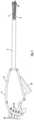
- Fig. 1shows an embodiment of a delivery device for delivering a graft or synthetic mesh for attachment to tissue.
- the term "graft"is used herein to indicate either a graft formed of biological material, or a synthetic mesh.
- the graftis connected to a plurality of flexible arms 4.
- the flexible arms as shown in Fig. 1extend from in a tube or shaft 6.
- the flexible armsare shown as being generally parallel to a central axis of the shaft. Since the flexible arms are flexible, some bending of the flexible arms means that they may not be strictly parallel, but are generally parallel, to the axis of travel of the rack 22 of the actuator while the flexible arms are in the position shown in Fig. 1 .
- Fig. 1 and Fig. 2show the device for delivery of graft for attachment to tissue, according to an embodiment, prior to deployment of the graft.
- Control wires 10are actuated to pull against sleeves 8 that surround a portion of the flexible arms 4.
- the control wiresextend through the shaft but may be external to the flexible arms as shown in Fig. 1 and Fig. 2 , or they may be internal to the flexible arms.
- the control wiresare connected to the sleeves at or near a distal end of the sleeves and control wires.
- each of the plurality of control wiresis associated with one of the plurality of the flexible arms. Upon actuation, the control wires pull against the sleeves at the point of attachment to the sleeves.
- control wiresare preferred to be nitinol wires, but the control wires may be formed of other metals, or plastics, textile materials or polymers, or similar materials having sufficient strength and flexibility.
- proximalis closest to the operator of the device and “distal” will typically be away from the operator and toward the patient when the device is in use.
- the actuator construct shown in Fig. 4A and Fig. 4 Bpulls the control wires 10, moving the flexible arms 4 to form a radial array ( Fig. 2 ). This action unfolds the graft to a spread and generally planar position.
- the flexible armsmay be positioned at an angle of somewhat more than 90° from the axis of travel of the actuator, or the central axis of the shaft.
- Fig. 14shows the flexible arms as positioned at an angle of more than 90° from the central axis of the shaft. In some embodiments, this angle could be up to 120° from the generally parallel position of the flexible arms shown in Fig. 1 .
- the actuatormay be designed to allow the operator to set the desired angle. In some embodiments, the angle may be at least 100° and perhaps more, so that the edges, or periphery, of the graft are pulled against the defect of the patient for subsequent securing or suturing of the graft.
- the devicemay comprise a housing 16 having a trigger or actuator lever 18.
- the housingmay form a housing for the mechanism of the invention, including the actuator construct for the control wires 10.
- At the distal end of the deviceis the plurality of spaced-apart flexible arms 4 that terminate at the connectors for the graft, which may be grasping jaws 24.
- the flexible arms 4are preferred to be formed of a flexible cable.
- the cablemay be a hollow cable formed of coiled or spirally-wound material which is capable of repetitive flexing and bending.
- the cablemay comprise stainless steel suitable for use in surgical applications.
- the cablesare sufficiently flexible to form the radial array shown in Fig. 2 when a force is applied by the control wires to the sleeves 8, but return to a flaccid condition as shown in Fig. 1 as the control wires cease pulling the flexible arms to the radial array.
- the flexible armsare preferred to be flexible along their entire length, without having preformed bends or angles that may tend to dictate a path of travel as the flexible arms are withdrawn from the surgical site.
- the flexible cables used with the sleeves (that are also flexible) and the control wiresallow the cables to follow the anatomical structure or host tissue, or a trocar, as a path of travel as the flexible arms are pulled away from the graft.
- the sleevesmay also be formed of hollow cable that is constructed and arranged to surround the flexible arms as shown in the drawing figures. Rigid members, rather than flexible cables, may tend to resist removal, due to anatomical structure or host tissue interfering with the path of travel.
- the flexible arms and the sleevesare preferred to have shape memory that allows them to return to about the shape shown in Fig. 1 or Fig 14A when the control wires are not actuated to apply a force upon the flexible arms,
- the embodiment as shown in Figs. 1 and 2has four (4) flexible arms 4. At least three (3), and preferably four (4) or more, flexible arms are employed. The flexible arms must be able to deploy and spread out the graft for attachment to tissue as shown in Fig. 14C .
- the flexible armsare formed in a radial array by force applied by the plurality of control wires 10.
- One control wireis associated with each flexible arm.
- the control wirespull against the sleeves 8 and the flexible arms to form the radial array.
- Fig. 2As shown in Fig. 1 , the flexible arms are substantially parallel to each other as they extend from shaft 6 of housing 16. No substantial tension is applied to the control wires in this configuration.
- the device with graft attachedmay be inserted into the surgical site incision in this configuration.
- control wires 10are actuated to pull against the sleeves 8, forming the flexible arms 4 into a radial array.
- the graft 2is positioned on the flexible arms and the graft expanded for attachment by movement of the flexible arms into the radial array.
- control wiresare actuated simultaneously by the actuator construct contained in housing 16.
- An actuation lever 18engages and rotates the ideal gear 22.
- the ideal gear 22moves the rack gear 20 upwardly, applying a pulling pressure to the control wires 10 to form the flexible arms into the radial array.
- the ideal gear and the rack gearform a rack and pinion construct.
- Latch 26has interlocking members that engage with each other to hold the flexible arms in the radial array when the rack gear reaches its fully upward position.
- the interlocking memberseach comprises hook that interlocks with the corresponding hook.
- the graftis thereby held in a positon for surgical attachment.
- a flexible arm release lever 28pushes an interlocking member of the latch away from an interlocking member that may be formed on the rack gear 20 to release the control wires. With no tension or pulling force on the control wires, the flexible arms return to generally the position of Fig. 1 . With tension released on the control wires, the flexible arms may be withdrawn through a trocar and/or surgical incision.
- connectors 24are positioned at or near the end of the flexible arms and are used to hold the graft for deployment.
- the connectorsclose upon the graft 2 to hold the graft.
- the connectorsmay be in the form of grasping jaws 24 in one embodiment that are actuated to close and open by pulling and releasing a connector strand, which may be a wire activation cable, or pull wire 56.
- a connector actuator construct as shown in Fig. 7 , Fig. 8 and Fig. 10communicates with the pull wire to open and close the connectors or grasping jaws for attachment and release of the graft.
- the connector actuatorcomprises a shuttle 40 in a preferred embodiment that ends with a control button 30 that extends from an end of the housing.
- the control buttonmay be unitary with the shuttle, since depressing the control button ( Fig. 8 ) moves the shuttle to open the connectors or grasping jaws.
- each control button and shuttleis associated with one flexible arm 4 and its associated grasping jaw.
- Each control buttonis associated with one grasping jaw. Actuating, or depressing, a control button associated with a grasping jaw causes it to open.
- the control buttonsare formed to individually lock the grasping jaws in an open position when the control button in depressed ( Fig. 3 ).
- Fig. 5is a top, sectioned view of the housing 16, showing two compartments, with one compartment on each side. The compartments may be separated by a divider 34.
- the lower compartment of the housingwhen viewing Fig. 5 , contains the mechanism of Fig. 4A and Fig.4B and applies a force to sleeves 8 by control wires 10. This mechanism actuates the flexible arms 4 to pull the flexible arms into the radial array, or release the flexible arms.
- the upper side of the housing as shown in Fig. 5has a cavity 36 to store a portion of the flexible arms as the length of the flexible arms is adjusted for the specific application of a graft.
- the length of the flexible arms 4may be adjusted by manually pulling or pushing the flexible arms into or out of the housing 16.
- Cavity 36 of the housingstores excess length of the flexible arms.
- the length adjustment featureis useful to adjust the size of the arm array to the dimensions, and particularly the perimeter, of the graft, so that the radial array of the device fits the graft and pulls the graft tight, but not tight enough to deform the flexible arms of the radial array.
- a frictional braking device 38( Fig.
- the frictional braking deviceapplies friction to each flexible arm that is sufficient to allow a length of each of the flexible arms to be pushed into or pulled from the housing, while preventing unwanted withdrawal or insertion of the flexible arms relative to the housing.
- the frictional braking devicemay be opposing sheets of vinyl, rubber, or similar compressible materials through which the flexible arms pass, and which applies a frictional force on the flexible arms.
- the frictional braking devicehas openings or conduits equal in number to the number of flexible arms.
- a cover of the housingmay have protrusion(s) or boss(es) 72 formed thereon that applies pressure to deform the braking device and conduits for the application of frictional pressure to the flexible arms.
- the length of the portion of the flexible arms that extend from the distal end of the devicemay be altered while still providing a workable mechanism for forming the radial array irrespective of the length of each flexible arm that is chosen.
- Separate mechanismsare provided for controlling the length of the flexible arms and opening and closing of the grasping jaws on one side of the housing 16 and the actuation of the sleeves to form the radial array on the other side of the housing.
- the graft 2is attached about its perimeter to each of the flexible arms 4.
- the graftis attached at spaced apart intervals so that the graft is formed in a radial array when the control wires are actuated.
- a portion of the graftis inserted between each open connector, which is a grasping jaw 24 in the embodiment shown. After insertion of a portion of the graft into the open grasping jaw, the grasping jaw is closed by releasing tension on the connector strand to hold the graft.
- the control buttons 30are released from their locked positions by one or more release buttons 32.
- Fig. 10A, 10BIn a preferred embodiment, the grasping jaws 24 each have a separate control button 30 and release button 32 so that the grasping jaws can each be independently opened and closed.
- Fig. 7shows housing 16 with flexible arms 4 attached to the grasping jaws 24, and extending from the cavity 36 of the housing and though shaft 6. This construct communicates with control buttons 30 to open the grasping jaws, which are normally closed. Anchor sites 46 for the flexible arms 4 are shown.
- Fig. 8is enlarged to show the detail of a preferred structure of the anchor sites.
- Shuttle 40communicates with an associated control button 30 (not shown in this figure).
- a set screw 42connects pull wire 56 to the shuttle.
- a compression spring 44tensions the control wire to hold the grasping jaw closed.
- An anchoring collar 46 for the flexible armis provided.
- Depressing release button 32( Fig. 10B ) allows the shuttle to be pushed proximally to compress the spring 44 and close the grasping jaws by providing tension on the pull wire.
- Fig. 9shows detail of an embodiment of the grasping jaws 24.
- the grasping jawsmay have an upper tooth 48 and a lower tooth 50 as shown, each of which pivot about a pivot pin 52.
- the upper tooth and the lower toothmay be housed in the jaw housing 54.
- a pair of pull wires 56that may be internal to the flexible arm 4 contract to open and close.
- the grasping jawsare preferred to be normally closed. Springs 44 apply tension to the pull wires so that the grasping jaws are closed until the shuttle 40 via control buttons 30 push the springs forward to relieve tension on the pull wires.
- Figs. 10A, 10Bshow the interaction between an embodiment of the shuttle 40 and release button 32.
- the shuttleis pushed forward by pressing control button 30. This action depresses spring 44 and opens the grasping jaw.
- An end of release button 32engages an opening in the shuttle due to shape memory properties of the release button, locking the shuttle in place with the grasping jaw open.
- Depressing release button 32disengages the end of the release button.
- Spring 44causes the shuttle to move from the position of Fig. 10A to the position of Fig. 10B .
- Expanded spring 44applies tension to the pull wires 56 to close the grasping jaws 24.
- a release button 32is provided for each flexible arm and associated grasping jaw.
- a bridgecould be provided so that the grasping jaws may be universally closed at once. After the grasping jaws are closed on the graft 2, the graft is held in place by the grasping jaws 24. After surgical attachment of the graft, the control buttons are actuated to release the graft from the grasping jaws.
- the control wires 10are also released from tension by the actuator construct, and the device is removed through the surgical site incision.
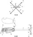
- Fig.12demonstrates the graft being attached to the device.
- the grasper jawsare opened using the control buttons 30.
- the graftis connected at four (4) points to the flexible arms using the grasper jaws and generally about the perimeter of the graft.
- the grasper jawsare closed on the graft to hold the graft.
- the actuatoris used to place the flexible arms in an orientation with the flexible arms generally parallel to each other for insertion through a trocar and into the surgical site.
- a sheath 64 for facilitating insertion of the flexible arms and graft into the trocar and to the surgical siteis shown.
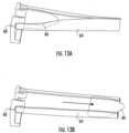
- Figs.13A-13DThe sheath in this embodiment is a split tube that may be transparent or translucent.
- the sheathis preferred to be tapered, or have a frusto-conical shape that tapers or progressively reduces in diameter from left to right when viewed as in the drawing figures.
- a stand 68holds an end of the sheath open at the split.
- a bullet shaped tool 66 having a diameter that is larger than the middle of the sheathmay be used to slide from the end of the sheath that is adjacent to the stand and along the sheath to the opposite end, forcing the sheath to open about the split.
- Fig. 13BA bullet shaped tool 66 having a diameter that is larger than the middle of the sheath may be used to slide from the end of the sheath that is adjacent to the stand and along the sheath to the opposite end, forcing the shea
- the sheathis open at the split to a width that permits insertion of the flexible arms and the graft.
- the sheath, attached to the device,is placed into the sheath through the split.
- the sheath and the deviceare removed from the stand for insertion into a trocar.
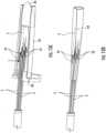
- Figs. 11A , 14Ashow a seal 62 mounted to the shaft 6.
- the sealengages the trocar and the shaft to form a seal, inhibiting gasses from escaping the belly of the patient.
- Fig. 14BAn O-ring may be present about a circumference 70 of the seal to improve sealing.
- a section of graft 2 of appropriate size to repair the subject herniais selected and/or formed.
- Fig 12The graft may be formed (of various biological materials or, synthetic materials, including, but not limited to polypropylene or polytetrafluoroethylene (PTFE).
- the graftis connected near its perimeter to the connectors near the distal ends of the flexible arms.
- Each flexible armis preferred to have a connector, such as grasping jaws 24.
- the activation lever 18is in the position shown in Fig. 1 , with the flexible arms positioned generally parallel to the axis of travel of the actuator.
- the graftis held by the flexible arms and folded.
- the graftis preferred to be covered by the sheath 64 for insertion into the trocar.
- An incision in tissue 84 of the patientis made at the approximate center of the defect.
- a trocar 82is present within the incision.
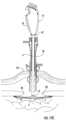
- Figs. 14A-CThe flexible arms of the device in a generally parallel orientation are inserted through the approximate center of the defect.
- Fig 14AThe sheath 64 facilitates insertion of the graft 2 into the trocar, and protects the graft as it moves through the trocar to the surgical site.
- Fig 14B.
- the actuatorsuch as the gear train of Fig 4A , is actuated causing the actuator to pull the control wires 10, the flexible arms 4 and associated graft to the position shown in Fig. 14 .
- the graftis pulled up against the tissue by means of the handle of the device to cover the hernia defect 80.
- Graft attachment to the tissuemay be provided by known methods of attachment of grafts at surgical sites such as hernia defects. The procedure may be monitored by use of a laparoscope for proper positioning, and securing, of the graft.
- the graftis formed to generally a planar form when the flexible arms form the radial array.
- the flexible armsmay move through an arc that is more than 90°. Therefore, the surface of the graft may be somewhat curved or non-planar, so that the edges or periphery of the graft is pushed against the tissue and secured to the tissue to cover the defect. However, the graft is still considered to be in a generally planar position.
- the flexible armsreturn to the position shown in Fig. 1 , Fig. 14A .
- the devicemay now be removed by pulling it upwardly through the trocar and away from the incision.
- the flexible armsby being flexible along their length, with no preformed angles, kinks or similar geometry, are sufficiently flexible to follow a path of retreat from the fully extended position of Fig. 2 to the position shown in Fig. 1 , without disrupting the sutured graft, while also being sufficiently rigid to support the graft for positioning and securement at the defect site.
Landscapes
- Health & Medical Sciences (AREA)
- Life Sciences & Earth Sciences (AREA)
- Public Health (AREA)
- General Health & Medical Sciences (AREA)
- Veterinary Medicine (AREA)
- Engineering & Computer Science (AREA)
- Biomedical Technology (AREA)
- Heart & Thoracic Surgery (AREA)
- Animal Behavior & Ethology (AREA)
- Surgery (AREA)
- Cardiology (AREA)
- Oral & Maxillofacial Surgery (AREA)
- Transplantation (AREA)
- Vascular Medicine (AREA)
- Molecular Biology (AREA)
- Medical Informatics (AREA)
- Pathology (AREA)
- Nuclear Medicine, Radiotherapy & Molecular Imaging (AREA)
- Surgical Instruments (AREA)
Description
- Biological grafts and synthetic mesh are used to repair anatomical defects, such as hernias. Delivery of the mesh or graft into body cavities either requires invasive surgery, or heretofore unsatisfactory laparoscopic methods.
- Hernias are structural defects most commonly involving the musculofascial tissues of the abdominal and pelvic regions within the human body. Most hernias eventually require surgical repair. Surgical repair of ventral incisional hernias may be accomplished via an "open method." This method involves making a sizable incision directly over the tissue defect, separating the contents of the hernia away from the musculofascial defect, and repairing the defect primarily using sutures, or more commonly, sewing a graft to the defect edge in tension-free manner. This is done in an effort to minimize the recurrence of hernia formation which may occur with some frequency. The recurrence may be due to multiple factors including general health of the patient, surgical technique, and types of mesh or graft utilized. Overall, this traditional method is effective, but also often involves more pain, long periods of disability following the surgery, higher perioperative infection rates, and an established hernia recurrence rate.
- Alternatively, ventral incisional hernias may be repaired using the "laparoscopic method." However, this method has its own set of major shortcomings principally related to higher degree of difficulty in performing this procedure. One of the major challenges involve graft introduction into the abdominal cavity. Typically, a graft is rolled tightly into a cylindrical configuration and subsequently, pushed/pulled through the trocar which can be both time consuming and frustrating, especially when a larger graft is needed to cover the defect. This maneuver can also damage the graft during the delivery due to excessive force used or needed during the delivery process. Some surgeons also elect to place multiple sutures within the periphery of the graft for transfascial securement. This is often done prior to introduction of the graft. Once delivered into the abdominal cavity, the rolled graft/suture combination is unrolled, sutures isolated into respective corresponding abdominal quadrants, and the graft is centered over the defect prior to fixation. These steps are often very challenging and frustrating to accomplish in an efficient manner due to the pliable property of the graft and sutures which is a desired characteristic.
US 2013/012966 A1 discloses a device for delivering a synthetic mesh or graft for anatomical repair at the defect site, with the synthetic mesh or graft in position for attachment to repair the defect. A plurality of spaced apart, flexible fingers is connected to the synthetic mesh or graft. The flexible fingers are initially in a position that is generally parallel to a direction of travel of the actuator. The actuator moves the plurality of flexible fingers from the initial to form a radial array, which opens or extends the synthetic mesh or graft. The synthetic mesh or graft may then be secured in place. US 2014/107675 A1 ,US 2017/172551 A1 ,US 2005/256532 A1 ,US 2010/069930 A1 , andUS 5 405 360 A disclose similar devices.- The present invention is a device for delivering a synthetic mesh or graft for anatomical repair at a defect site. The invention is defined in
claim 1. Further embodiments are defined in the dependent claims. No surgical methods form part of the invention. A plurality of flexible arms is connected to the synthetic mesh or graft. Grasping jaws are individually controlled at or near a proximal end of the device for connection of the graft and release of the graft at the surgical site. The flexible arms, with graft attached are positioned through a surgical incision to the defect site. An actuator positions the flexible arms to assume a radial array at the surgical site, unfolding and spreading the graft for attachment. The length of each flexible arm is individually adjustable to adapt to the size and shape of the graft selected for installation at the defect site to repair the defect. Fig. 1 is a side elevation of an embodiment of the invention.Fig. 2 shows the embodiment ofFig. 1 with theflexible arms 4 in a deployed position.Fig. 3 shows flexible arms of the embodiment ofFig. 1 with thegrasping jaws 24 at an end of each flexible arm in an open position for receiving a graft.Fig. 4A is a sectioned view in an embodiment similar to that ofFig. 1 showing the actuation mechanism for extending and retracting the flexible arms with the flexible arms extended.Fig. 4B is a sectioned view of the embodiment of the invention shown inFig. 4A with the flexible arms retracted.Fig. 5 is a sectioned view of an embodiment of the invention showing actuators inhousing 16.Fig. 6A is an elevation of an embodiment of the invention taken from a proximal end of the invention.Fig. 6B demonstrates a cover for the housing removed from the device.Fig. 7 is an elevation of one side of an embodiment of the invention with the cover removed fromhousing 16.Fig. 8 is an enlarged isolation of a portion of the actuators for graspingjaws 24.Fig. 9 is an isolation of an embodiment of agrasping jaw 24.Fig. 10A andFig 10B are isolations of a portion of the actuator for the grasping jaws sectioned to demonstrate the action ofrelease button 32.Fig. 11A shows the device according to an embodiment of the invention with a graft affixed to it.Fig. 11B is a side sectioned view of a seal that slidably attaches to a shaft of the device for sealing a trocar.Fig. 12 demonstrates attachment of the graft to the embodiment of the device as shown in the drawing figures.Fig. 13A shows a sheath that covers the graft to facilitate insertion of the graft and a portion of the device through a trocar and into the surgical site.Fig. 13B demonstrates a step of opening of a split in the sheath for insertion of the device with graft into the sheath.Fig. 13C shows the step of positioning the device with graft into the sheath.Fig. 13D shows the device with graft in the sheath and surrounding the sheath.Figs. 14A-14C demonstrate deployment of the graft through a trocar and into the surgical site using the device according to an embodiment of the device.- Turning now to the drawing figures,
Fig. 1 shows an embodiment of a delivery device for delivering a graft or synthetic mesh for attachment to tissue. The term "graft" is used herein to indicate either a graft formed of biological material, or a synthetic mesh. The graft is connected to a plurality offlexible arms 4. The flexible arms as shown inFig. 1 extend from in a tube orshaft 6. The flexible arms are shown as being generally parallel to a central axis of the shaft. Since the flexible arms are flexible, some bending of the flexible arms means that they may not be strictly parallel, but are generally parallel, to the axis of travel of therack 22 of the actuator while the flexible arms are in the position shown inFig. 1 . Fig. 1 andFig. 2 show the device for delivery of graft for attachment to tissue, according to an embodiment, prior to deployment of the graft.Control wires 10 are actuated to pull againstsleeves 8 that surround a portion of theflexible arms 4. The control wires extend through the shaft but may be external to the flexible arms as shown inFig. 1 andFig. 2 , or they may be internal to the flexible arms. The control wires are connected to the sleeves at or near a distal end of the sleeves and control wires. In a preferred embodiment, each of the plurality of control wires is associated with one of the plurality of the flexible arms. Upon actuation, the control wires pull against the sleeves at the point of attachment to the sleeves. The force of the control wires acting on the sleeves pulls the flexible arms from the position shown inFig. 1 and into a radial array as demonstrated inFig. 2 . The control wires are preferred to be nitinol wires, but the control wires may be formed of other metals, or plastics, textile materials or polymers, or similar materials having sufficient strength and flexibility.- As used herein, "proximal" is closest to the operator of the device and "distal" will typically be away from the operator and toward the patient when the device is in use.
- The actuator construct shown in
Fig. 4A andFig. 4 B pulls thecontrol wires 10, moving theflexible arms 4 to form a radial array (Fig. 2 ). This action unfolds the graft to a spread and generally planar position. In a preferred embodiment, when the travel of theactuator lever 18 is fully exhausted, the flexible arms may be positioned at an angle of somewhat more than 90° from the axis of travel of the actuator, or the central axis of the shaft.Fig. 14 shows the flexible arms as positioned at an angle of more than 90° from the central axis of the shaft. In some embodiments, this angle could be up to 120° from the generally parallel position of the flexible arms shown inFig. 1 . The actuator may be designed to allow the operator to set the desired angle. In some embodiments, the angle may be at least 100° and perhaps more, so that the edges, or periphery, of the graft are pulled against the defect of the patient for subsequent securing or suturing of the graft. - According to one embodiment of the invention, the device may comprise a
housing 16 having a trigger oractuator lever 18. The housing may form a housing for the mechanism of the invention, including the actuator construct for thecontrol wires 10. At the distal end of the device is the plurality of spaced-apartflexible arms 4 that terminate at the connectors for the graft, which may be graspingjaws 24. - The
flexible arms 4 are preferred to be formed of a flexible cable. The cable may be a hollow cable formed of coiled or spirally-wound material which is capable of repetitive flexing and bending. The cable may comprise stainless steel suitable for use in surgical applications. The cables are sufficiently flexible to form the radial array shown inFig. 2 when a force is applied by the control wires to thesleeves 8, but return to a flaccid condition as shown inFig. 1 as the control wires cease pulling the flexible arms to the radial array. The flexible arms are preferred to be flexible along their entire length, without having preformed bends or angles that may tend to dictate a path of travel as the flexible arms are withdrawn from the surgical site. The flexible cables used with the sleeves (that are also flexible) and the control wires allow the cables to follow the anatomical structure or host tissue, or a trocar, as a path of travel as the flexible arms are pulled away from the graft. The sleeves may also be formed of hollow cable that is constructed and arranged to surround the flexible arms as shown in the drawing figures. Rigid members, rather than flexible cables, may tend to resist removal, due to anatomical structure or host tissue interfering with the path of travel. The flexible arms and the sleeves are preferred to have shape memory that allows them to return to about the shape shown inFig. 1 orFig 14A when the control wires are not actuated to apply a force upon the flexible arms, - The embodiment as shown in
Figs. 1 and2 has four (4)flexible arms 4. At least three (3), and preferably four (4) or more, flexible arms are employed. The flexible arms must be able to deploy and spread out the graft for attachment to tissue as shown inFig. 14C . - The flexible arms are formed in a radial array by force applied by the plurality of
control wires 10. One control wire is associated with each flexible arm. The control wires pull against thesleeves 8 and the flexible arms to form the radial array.Fig. 2 . As shown inFig. 1 , the flexible arms are substantially parallel to each other as they extend fromshaft 6 ofhousing 16. No substantial tension is applied to the control wires in this configuration. The device with graft attached may be inserted into the surgical site incision in this configuration. - In
Fig. 2 , thecontrol wires 10 are actuated to pull against thesleeves 8, forming theflexible arms 4 into a radial array. In use, thegraft 2 is positioned on the flexible arms and the graft expanded for attachment by movement of the flexible arms into the radial array. - In an embodiment as shown in
Figs. 4A and4B , the control wires are actuated simultaneously by the actuator construct contained inhousing 16. Anactuation lever 18 engages and rotates theideal gear 22. Theideal gear 22 moves therack gear 20 upwardly, applying a pulling pressure to thecontrol wires 10 to form the flexible arms into the radial array. The ideal gear and the rack gear form a rack and pinion construct. Latch 26 has interlocking members that engage with each other to hold the flexible arms in the radial array when the rack gear reaches its fully upward position. The interlocking members each comprises hook that interlocks with the corresponding hook. The graft is thereby held in a positon for surgical attachment. A flexiblearm release lever 28 pushes an interlocking member of the latch away from an interlocking member that may be formed on therack gear 20 to release the control wires. With no tension or pulling force on the control wires, the flexible arms return to generally the position ofFig. 1 . With tension released on the control wires, the flexible arms may be withdrawn through a trocar and/or surgical incision.- In the embodiment of the device shown in
Figs. 1 through3 ,connectors 24 are positioned at or near the end of the flexible arms and are used to hold the graft for deployment. The connectors close upon thegraft 2 to hold the graft. The connectors may be in the form of graspingjaws 24 in one embodiment that are actuated to close and open by pulling and releasing a connector strand, which may be a wire activation cable, or pullwire 56. A connector actuator construct as shown inFig. 7 ,Fig. 8 andFig. 10 communicates with the pull wire to open and close the connectors or grasping jaws for attachment and release of the graft. The connector actuator comprises ashuttle 40 in a preferred embodiment that ends with acontrol button 30 that extends from an end of the housing. The control button may be unitary with the shuttle, since depressing the control button (Fig. 8 ) moves the shuttle to open the connectors or grasping jaws. In this embodiment, each control button and shuttle is associated with oneflexible arm 4 and its associated grasping jaw. Each control button is associated with one grasping jaw. Actuating, or depressing, a control button associated with a grasping jaw causes it to open. Preferably, the control buttons are formed to individually lock the grasping jaws in an open position when the control button in depressed (Fig. 3 ). Fig. 5 is a top, sectioned view of thehousing 16, showing two compartments, with one compartment on each side. The compartments may be separated by adivider 34. The lower compartment of the housing, when viewingFig. 5 , contains the mechanism ofFig. 4A andFig.4B and applies a force tosleeves 8 bycontrol wires 10. This mechanism actuates theflexible arms 4 to pull the flexible arms into the radial array, or release the flexible arms.- The upper side of the housing as shown in
Fig. 5 has acavity 36 to store a portion of the flexible arms as the length of the flexible arms is adjusted for the specific application of a graft. The length of theflexible arms 4 may be adjusted by manually pulling or pushing the flexible arms into or out of thehousing 16.Cavity 36 of the housing stores excess length of the flexible arms. The length adjustment feature is useful to adjust the size of the arm array to the dimensions, and particularly the perimeter, of the graft, so that the radial array of the device fits the graft and pulls the graft tight, but not tight enough to deform the flexible arms of the radial array. A frictional braking device38 (Fig. 6B ) is preferred to be positioned near the entry/exit of thecavity 36 of the housing to apply friction to the flexible arms. The frictional braking device applies friction to each flexible arm that is sufficient to allow a length of each of the flexible arms to be pushed into or pulled from the housing, while preventing unwanted withdrawal or insertion of the flexible arms relative to the housing. The frictional braking device may be opposing sheets of vinyl, rubber, or similar compressible materials through which the flexible arms pass, and which applies a frictional force on the flexible arms. In a preferred embodiment, the frictional braking device has openings or conduits equal in number to the number of flexible arms. Each flexible arm engages one of the conduits and the conduit applies a frictional force to the flexible arm to retard but not prevent movement of the flexible arm into and out of the cavity as described. A cover of the housing may have protrusion(s) or boss(es)72 formed thereon that applies pressure to deform the braking device and conduits for the application of frictional pressure to the flexible arms. - By the
control wires 10 acting on the sleeves, with theflexible arms 4 being slidable relative to thesleeves 8, the length of the portion of the flexible arms that extend from the distal end of the device may be altered while still providing a workable mechanism for forming the radial array irrespective of the length of each flexible arm that is chosen. Separate mechanisms are provided for controlling the length of the flexible arms and opening and closing of the grasping jaws on one side of thehousing 16 and the actuation of the sleeves to form the radial array on the other side of the housing. - The
graft 2 is attached about its perimeter to each of theflexible arms 4. The graft is attached at spaced apart intervals so that the graft is formed in a radial array when the control wires are actuated. A portion of the graft is inserted between each open connector, which is a graspingjaw 24 in the embodiment shown. After insertion of a portion of the graft into the open grasping jaw, the grasping jaw is closed by releasing tension on the connector strand to hold the graft. Thecontrol buttons 30 are released from their locked positions by one ormore release buttons 32.Fig. 10A, 10B . In a preferred embodiment, the graspingjaws 24 each have aseparate control button 30 andrelease button 32 so that the grasping jaws can each be independently opened and closed. Fig. 7 showshousing 16 withflexible arms 4 attached to the graspingjaws 24, and extending from thecavity 36 of the housing and thoughshaft 6. This construct communicates withcontrol buttons 30 to open the grasping jaws, which are normally closed.Anchor sites 46 for theflexible arms 4 are shown.Fig. 8 is enlarged to show the detail of a preferred structure of the anchor sites.Shuttle 40 communicates with an associated control button30 (not shown in this figure). Aset screw 42 connectspull wire 56 to the shuttle. Acompression spring 44 tensions the control wire to hold the grasping jaw closed. Ananchoring collar 46 for the flexible arm is provided. Depressing release button32 (Fig. 10B ) allows the shuttle to be pushed proximally to compress thespring 44 and close the grasping jaws by providing tension on the pull wire.Fig. 9 shows detail of an embodiment of the graspingjaws 24. The grasping jaws may have anupper tooth 48 and alower tooth 50 as shown, each of which pivot about apivot pin 52. The upper tooth and the lower tooth may be housed in thejaw housing 54. A pair ofpull wires 56 that may be internal to theflexible arm 4 contract to open and close. The grasping jaws are preferred to be normally closed.Springs 44 apply tension to the pull wires so that the grasping jaws are closed until theshuttle 40 viacontrol buttons 30 push the springs forward to relieve tension on the pull wires.Figs. 10A, 10B show the interaction between an embodiment of theshuttle 40 andrelease button 32. As shown inFig. 10A , the shuttle is pushed forward by pressingcontrol button 30. This action depressesspring 44 and opens the grasping jaw. An end ofrelease button 32 engages an opening in the shuttle due to shape memory properties of the release button, locking the shuttle in place with the grasping jaw open.- Depressing
release button 32 disengages the end of the release button.Spring 44 causes the shuttle to move from the position ofFig. 10A to the position ofFig. 10B .Expanded spring 44 applies tension to thepull wires 56 to close the graspingjaws 24. In the embodiment shown, arelease button 32 is provided for each flexible arm and associated grasping jaw. However, a bridge could be provided so that the grasping jaws may be universally closed at once. After the grasping jaws are closed on thegraft 2, the graft is held in place by the graspingjaws 24. After surgical attachment of the graft, the control buttons are actuated to release the graft from the grasping jaws. Thecontrol wires 10 are also released from tension by the actuator construct, and the device is removed through the surgical site incision. Fig.12 demonstrates the graft being attached to the device. The grasper jaws are opened using thecontrol buttons 30. In this embodiment, the graft is connected at four (4) points to the flexible arms using the grasper jaws and generally about the perimeter of the graft. The grasper jaws are closed on the graft to hold the graft. The actuator is used to place the flexible arms in an orientation with the flexible arms generally parallel to each other for insertion through a trocar and into the surgical site.- A
sheath 64 for facilitating insertion of the flexible arms and graft into the trocar and to the surgical site is shown.Figs.13A-13D . The sheath in this embodiment is a split tube that may be transparent or translucent. The sheath is preferred to be tapered, or have a frusto-conical shape that tapers or progressively reduces in diameter from left to right when viewed as in the drawing figures. Astand 68 holds an end of the sheath open at the split. A bullet shapedtool 66 having a diameter that is larger than the middle of the sheath may be used to slide from the end of the sheath that is adjacent to the stand and along the sheath to the opposite end, forcing the sheath to open about the split.Fig. 13B . The sheath is open at the split to a width that permits insertion of the flexible arms and the graft. The sheath, attached to the device, is placed into the sheath through the split. The sheath and the device are removed from the stand for insertion into a trocar. Figs. 11A ,14A show aseal 62 mounted to theshaft 6. The seal engages the trocar and the shaft to form a seal, inhibiting gasses from escaping the belly of the patient.Fig. 14B . An O-ring may be present about acircumference 70 of the seal to improve sealing.- In use, according to one embodiment, a section of
graft 2 of appropriate size to repair the subject hernia is selected and/or formed.Fig 12 . The graft may be formed (of various biological materials or, synthetic materials, including, but not limited to polypropylene or polytetrafluoroethylene (PTFE). The graft is connected near its perimeter to the connectors near the distal ends of the flexible arms. Each flexible arm is preferred to have a connector, such as graspingjaws 24. Theactivation lever 18 is in the position shown inFig. 1 , with the flexible arms positioned generally parallel to the axis of travel of the actuator. The graft is held by the flexible arms and folded. The graft is preferred to be covered by thesheath 64 for insertion into the trocar. - An incision in
tissue 84 of the patient is made at the approximate center of the defect. Preferably, atrocar 82 is present within the incision.Figs. 14A-C. The flexible arms of the device in a generally parallel orientation are inserted through the approximate center of the defect.Fig 14A . Thesheath 64 facilitates insertion of thegraft 2 into the trocar, and protects the graft as it moves through the trocar to the surgical site.Fig 14B . After the distal end of the device with graft attached travels through the trocar, and sufficient clearance through thedefect 80 is obtained, the actuator, such as the gear train ofFig 4A , is actuated causing the actuator to pull thecontrol wires 10, theflexible arms 4 and associated graft to the position shown inFig. 14 . The graft is pulled up against the tissue by means of the handle of the device to cover thehernia defect 80. Graft attachment to the tissue may be provided by known methods of attachment of grafts at surgical sites such as hernia defects. The procedure may be monitored by use of a laparoscope for proper positioning, and securing, of the graft. - The graft is formed to generally a planar form when the flexible arms form the radial array. As noted, the flexible arms may move through an arc that is more than 90°. Therefore, the surface of the graft may be somewhat curved or non-planar, so that the edges or periphery of the graft is pushed against the tissue and secured to the tissue to cover the defect. However, the graft is still considered to be in a generally planar position.
- After the
connectors 24 are released from the graft as described above, tension is released from thecontrol wires 10. The flexible arms return to the position shown inFig. 1 ,Fig. 14A . The device may now be removed by pulling it upwardly through the trocar and away from the incision. The flexible arms, by being flexible along their length, with no preformed angles, kinks or similar geometry, are sufficiently flexible to follow a path of retreat from the fully extended position ofFig. 2 to the position shown inFig. 1 , without disrupting the sutured graft, while also being sufficiently rigid to support the graft for positioning and securement at the defect site.
Claims (14)
- A device for delivery of a graft (2) for attachment to tissue, comprising:a plurality of flexible arms (4) and a plurality of sleeves (8), wherein each sleeve of the plurality of sleeves surrounds a portion of one of the flexible arms of the plurality of flexible arms;an actuator (18) , wherein movement of the actuator moves the plurality of sleeves and each sleeve of the plurality of sleeves moves the flexible arm it surrounds, and movement of the actuator forms the plurality of arms into a radial array;wherein each of the flexible arms is slidable relative to the sleeve that surrounds it so that a length of a portion of each of the flexible arms that extends distally from the sleeve that surrounds it is adjustable;wherein the plurality of sleeves (8) are in communication with the actuator (18), and move in response to movement of the actuator.
- A device for delivery of a graft for attachment to tissue as claimed in claim 1 wherein the communication between the actuator and the sleeves is by control wires (10) connected to the sleeves for actuated pulling thereof.
- A device for delivery of a graft for attachment to tissue as claimed in claim 1 or claim 2, further comprising a brake, wherein each of the plurality of flexible arms frictionally engages the brake.
- A device for delivery of a graft for attachment to tissue as claimed in claim 3, wherein the brake comprises a plurality of channels formed therein, and each of the plurality of flexible arms frictionally engages a channel of the plurality of channels of the brake.
- A device for delivery of a graft for attachment to tissue as claimed in any of the preceding claims, wherein a portion of each of the flexible arms is slidable into a chamber of a housing (16), and wherein the actuator is contained in the housing.
- A device for delivery of a graft for attachment to tissue as claimed in any of the preceding claims comprising three of said flexible arms, wherein each flexible arm comprises a connector (24) at a distal end of each flexible arm, and wherein each connector is constructed to open and close, and each connector is constructed to close on a graft, and the flexible arms hold the graft in the radial array when the actuator pulls the plurality of flexible arms into the radial array.
- A device for delivery of a graft for attachment to tissue as claimed in Claim 6 wherein each connector of each flexible arm is constructed to open and close separately from every other connector.
- A device for delivery of a graft for attachment to tissue as claimed in claim 7 wherein the housing in which the actuator is contained comprises three connector actuators, and closing of each flexible arm is actuated by a corresponding connector actuator of the three connector actuators.
- A device for delivery of a graft for attachment to tissue as claimed in claim 8 wherein the housing comprises a release actuator (32), wherein the release actuator actuates tension on a connector linkage and causes the connector to close.
- A device for delivery of a graft for attachment to tissue as claimed in any of the preceding claims, wherein the actuator comprises a rack and pinion.
- A device for delivery of a graft for attachment to tissue as claimed in claim 10 wherein the rack and pinion is arranged so that rotation of the pinion by a lever actuates movement of the rack, wherein the rack communicates with the flexible arms and wherein movement of the rack forms the flexible arms into a radial array.
- A device for delivery of a graft for attachment to tissue as claimed in any of the preceding claims, further comprising a sheath having a longitudinal split along a length thereof, and wherein a distal end of the flexible arms and a graft connected to the flexible arms are positioned within the sheath and the sheath surrounds the graft.
- A device for delivery of a graft for attachment to tissue as claimed in claim 12 comprising three of said flexible arms, wherein the sheath which surrounds the graft is constructed and arranged to insert into a trocar, wherein each flexible arm comprises a connector at a distal end of each flexible arm, and wherein each connector is constructed to open and close on a graft.
- A device as claimed in any of the preceding claims wherein the actuator is adapted to position the flexible arms to assume a radial array at the surgical site, so as to unfold and spread the graft (2) for attachment, the length of each flexible arm being individually adjustable so as to adapt to the size and shape of the graft selected for installation at the surgical site.
Applications Claiming Priority (2)
| Application Number | Priority Date | Filing Date | Title |
|---|---|---|---|
| US201762529262P | 2017-07-06 | 2017-07-06 | |
| PCT/US2018/041147WO2019010454A1 (en) | 2017-07-06 | 2018-07-06 | Device for delivering grafts at a surgical site and method |
Publications (3)
| Publication Number | Publication Date |
|---|---|
| EP3648677A1 EP3648677A1 (en) | 2020-05-13 |
| EP3648677A4 EP3648677A4 (en) | 2021-01-27 |
| EP3648677B1true EP3648677B1 (en) | 2025-02-26 |
Family
ID=64904381
Family Applications (1)
| Application Number | Title | Priority Date | Filing Date |
|---|---|---|---|
| EP18827775.0AActiveEP3648677B1 (en) | 2017-07-06 | 2018-07-06 | Device for delivering grafts at a surgical site |
Country Status (4)
| Country | Link |
|---|---|
| US (2) | US10898310B2 (en) |
| EP (1) | EP3648677B1 (en) |
| CA (1) | CA3068972A1 (en) |
| WO (1) | WO2019010454A1 (en) |
Families Citing this family (1)
| Publication number | Priority date | Publication date | Assignee | Title |
|---|---|---|---|---|
| US11090145B2 (en)* | 2017-07-06 | 2021-08-17 | Park Surgical Innovations, Llc | Device for delivering grafts at a surgical site and method |
Family Cites Families (52)
| Publication number | Priority date | Publication date | Assignee | Title |
|---|---|---|---|---|
| US5147316A (en) | 1990-11-19 | 1992-09-15 | Castillenti Thomas A | Laparoscopic trocar with self-locking port sleeve |
| US5234443A (en)* | 1991-07-26 | 1993-08-10 | The Regents Of The University Of California | Endoscopic knot tying apparatus and methods |
| CA2089999A1 (en) | 1992-02-24 | 1993-08-25 | H. Jonathan Tovey | Resilient arm mesh deployer |
| US5395367A (en)* | 1992-07-29 | 1995-03-07 | Wilk; Peter J. | Laparoscopic instrument with bendable shaft and removable actuator |
| US5312391A (en)* | 1992-07-29 | 1994-05-17 | Wilk Peter J | Laparoscopic instrument assembly |
| US5379754A (en) | 1992-07-30 | 1995-01-10 | United States Surgical Corporation | Method using approximating apparatus for hernia repair |
| US6036699A (en)* | 1992-12-10 | 2000-03-14 | Perclose, Inc. | Device and method for suturing tissue |
| US5755713A (en)* | 1996-06-03 | 1998-05-26 | Bilof; Michael L. | Laparoscopic instrument assembly including a plurality of instruments |
| US5957939A (en) | 1997-07-31 | 1999-09-28 | Imagyn Medical Technologies, Inc. | Medical device for deploying surgical fabrics |
| US6669735B1 (en) | 1998-07-31 | 2003-12-30 | Davol, Inc. | Prosthesis for surgical treatment of hernia |
| EP1224918A3 (en) | 1999-05-10 | 2002-12-18 | endoVia Medical Inc. | Surgical instrument |
| US7615076B2 (en) | 1999-10-20 | 2009-11-10 | Anulex Technologies, Inc. | Method and apparatus for the treatment of the intervertebral disc annulus |
| US6425924B1 (en) | 2000-03-31 | 2002-07-30 | Ethicon, Inc. | Hernia repair prosthesis |
| US6478803B1 (en) | 2000-05-19 | 2002-11-12 | Genzyme Corporation | Device for delivery of surgical materials |
| AU2002322374B2 (en) | 2001-06-29 | 2006-10-26 | Intuitive Surgical, Inc. | Platform link wrist mechanism |
| TR200202198A2 (en) | 2002-09-13 | 2004-04-21 | Zafer Malazgirt | Patch-plug used to repair large trocar holes after laparoscopic surgery |
| US20040199052A1 (en) | 2003-04-01 | 2004-10-07 | Scimed Life Systems, Inc. | Endoscopic imaging system |
| EP1617766B1 (en) | 2003-04-22 | 2015-08-05 | Patrick Leahy | A device for use in parietal surgery |
| US8100824B2 (en) | 2003-05-23 | 2012-01-24 | Intuitive Surgical Operations, Inc. | Tool with articulation lock |
| WO2005016389A2 (en) | 2003-08-04 | 2005-02-24 | Kelly Jackson | Medical instruments and methods for using the same |
| US20050256532A1 (en)* | 2004-05-12 | 2005-11-17 | Asha Nayak | Cardiovascular defect patch device and method |
| US7931661B2 (en) | 2004-06-14 | 2011-04-26 | Usgi Medical, Inc. | Apparatus and methods for performing transluminal gastrointestinal procedures |
| US7662112B2 (en) | 2005-05-13 | 2010-02-16 | Kci Licensing, Inc. | Medical measuring device and method |
| WO2007030676A2 (en) | 2005-09-09 | 2007-03-15 | University Of South Florida | Laparoscopic hernia mesh spreader |
| US20090254103A1 (en) | 2006-03-29 | 2009-10-08 | Deutsch Harvey L | Method and device for cavity obliteration |
| US8518024B2 (en)* | 2006-04-24 | 2013-08-27 | Transenterix, Inc. | System and method for multi-instrument surgical access using a single access port |
| US20080071343A1 (en)* | 2006-09-15 | 2008-03-20 | Kevin John Mayberry | Multi-segmented graft deployment system |
| EP2099385B1 (en) | 2006-11-27 | 2021-02-24 | Davol Inc. | A device especially useful for hernia repair surgeries |
| US7947054B2 (en) | 2007-02-14 | 2011-05-24 | EasyLab Ltd. | Mesh deployment apparatus |
| US8303615B2 (en) | 2007-03-12 | 2012-11-06 | Bayer Healthcare Llc | Lancet-eject mechanism |
| US8808314B2 (en) | 2008-02-18 | 2014-08-19 | Covidien Lp | Device and method for deploying and attaching an implant to a biological tissue |
| US8968355B2 (en) | 2008-08-04 | 2015-03-03 | Covidien Lp | Articulating surgical device |
| WO2010033189A1 (en)* | 2008-09-16 | 2010-03-25 | VentralFix, Inc. | Method and apparatus for minimally invasive delivery, tensioned deployment and fixation of secondary material prosthetic devices in patient body tissue, including hernia repair within the patient's herniation site |
| US20100130850A1 (en) | 2008-11-25 | 2010-05-27 | Pakter Robert L | Flexible Core Surgical Device |
| US9011414B2 (en)* | 2009-04-04 | 2015-04-21 | Adam Judd Hansen | Systems and methods for hernia repair |
| US8641699B2 (en) | 2009-04-04 | 2014-02-04 | Adam J. Hansen | Systems and methods for hernia repair |
| US20110015491A1 (en)* | 2009-07-16 | 2011-01-20 | Sundaram Ravikumar | Surgical access device with moveable device port |
| WO2011137224A1 (en) | 2010-04-29 | 2011-11-03 | Danny Azriel Sherwinter | Systems and methods for facilitating closure of bodily openings |
| JP5851499B2 (en)* | 2010-06-25 | 2016-02-03 | マツィエイ ジェイ. チェトゥラキス, | Single-port laparoscopic access with laterally spaced virtual insertion points |
| US20120078244A1 (en)* | 2010-09-24 | 2012-03-29 | Worrell Barry C | Control features for articulating surgical device |
| TWM414932U (en) | 2011-01-21 | 2011-11-01 | xiang-de Zeng | Slewing structure for handheld endoscope |
| KR101259701B1 (en) | 2011-03-24 | 2013-05-06 | 정창욱 | Instrument for Minimally Invasive Surgery Having Curved Shaft |
| US9339365B2 (en)* | 2011-07-07 | 2016-05-17 | David D. Park | Device and method for delivering grafts |
| US20130012958A1 (en) | 2011-07-08 | 2013-01-10 | Stanislaw Marczyk | Surgical Device with Articulation and Wrist Rotation |
| EP2734121A2 (en) | 2011-07-11 | 2014-05-28 | Agile Endosurgery, Inc. | Articulated surgical tool |
| US8616460B2 (en) | 2011-07-13 | 2013-12-31 | Eastman Kodak Company | Method for providing dynamic optical illusion images |
| US9211134B2 (en) | 2012-04-09 | 2015-12-15 | Carefusion 2200, Inc. | Wrist assembly for articulating laparoscopic surgical instruments |
| US20140148828A1 (en)* | 2012-11-28 | 2014-05-29 | Usgi Medical, Inc. | Apparatus and methods for forming and securing gastrointestinal tissue folds |
| US20140276914A1 (en)* | 2013-03-14 | 2014-09-18 | Gyrus ACMI. Inc., d.b.a. Olympus Surgical Technologies America | Vaginal cuff closure tool and method |
| JP6110935B2 (en)* | 2013-03-29 | 2017-04-05 | 富士フイルム株式会社 | Surgical device and mantle |
| US20150119851A1 (en)* | 2013-10-30 | 2015-04-30 | Nordson Corporation | Instrument and method for delivery, deployment, and tamponade of hemostats and methods of assembling an instrument therefor |
| US20170172551A1 (en)* | 2015-12-18 | 2017-06-22 | Rao Innovations Llc. | Fascia Closure Tool |
- 2018
- 2018-07-06EPEP18827775.0Apatent/EP3648677B1/enactiveActive
- 2018-07-06USUS16/029,447patent/US10898310B2/enactiveActive
- 2018-07-06WOPCT/US2018/041147patent/WO2019010454A1/ennot_activeCeased
- 2018-07-06CACA3068972Apatent/CA3068972A1/enactivePending
- 2021
- 2021-01-25USUS17/157,504patent/US20210153996A1/enactivePending
Also Published As
| Publication number | Publication date |
|---|---|
| EP3648677A1 (en) | 2020-05-13 |
| WO2019010454A1 (en) | 2019-01-10 |
| US20190008622A1 (en) | 2019-01-10 |
| US20210153996A1 (en) | 2021-05-27 |
| EP3648677A4 (en) | 2021-01-27 |
| CA3068972A1 (en) | 2019-01-10 |
| US10898310B2 (en) | 2021-01-26 |
Similar Documents
| Publication | Publication Date | Title |
|---|---|---|
| JP7198876B2 (en) | Systems, devices and related methods for retracting tissue | |
| US20220240925A1 (en) | Minimally-invasive tissue suturing device | |
| EP1706043B1 (en) | Devices for tissue invagination | |
| JP4782421B2 (en) | Device for fastening tissue layers | |
| EP1819266B1 (en) | Remote tissue retraction device | |
| US7156857B2 (en) | Endoscopic instruments | |
| EP3795115A1 (en) | Device for delivering grafts at a surgical site | |
| US10925638B2 (en) | Device and method for delivering grafts | |
| EP2558023A2 (en) | Surgical spreadable sheet delivery and positioning system and method | |
| US11446023B2 (en) | Helical tissue anchor device and delivery system | |
| CA2803845A1 (en) | Tissue retractor assembly | |
| KR20190133719A (en) | Apparatus and method for tissue retraction | |
| JP2024504400A (en) | Repositionable clip with extension | |
| US20210153996A1 (en) | Device for delivering grafts at a surgical site and method | |
| US20180296200A1 (en) | Methods and devices for manipulating and fastening tissue | |
| EP2774547B1 (en) | Device for manipulating and fastening tissue | |
| US20230036602A1 (en) | Methods and devices for manipulating and fastening tissue | |
| US20240138836A1 (en) | Surgical clip and deployment system | |
| WO2025170737A1 (en) | Repositionable over-the-scope clip | |
| MXPA96004364A (en) | Method and apparatus for introducing a prote |
Legal Events
| Date | Code | Title | Description |
|---|---|---|---|
| STAA | Information on the status of an ep patent application or granted ep patent | Free format text:STATUS: THE INTERNATIONAL PUBLICATION HAS BEEN MADE | |
| PUAI | Public reference made under article 153(3) epc to a published international application that has entered the european phase | Free format text:ORIGINAL CODE: 0009012 | |
| STAA | Information on the status of an ep patent application or granted ep patent | Free format text:STATUS: REQUEST FOR EXAMINATION WAS MADE | |
| 17P | Request for examination filed | Effective date:20200121 | |
| AK | Designated contracting states | Kind code of ref document:A1 Designated state(s):AL AT BE BG CH CY CZ DE DK EE ES FI FR GB GR HR HU IE IS IT LI LT LU LV MC MK MT NL NO PL PT RO RS SE SI SK SM TR | |
| AX | Request for extension of the european patent | Extension state:BA ME | |
| DAV | Request for validation of the european patent (deleted) | ||
| DAX | Request for extension of the european patent (deleted) | ||
| A4 | Supplementary search report drawn up and despatched | Effective date:20210112 | |
| RIC1 | Information provided on ipc code assigned before grant | Ipc:A61F 2/00 20060101ALI20201221BHEP Ipc:A61F 2/90 20130101ALI20201221BHEP Ipc:A61B 17/00 20060101AFI20201221BHEP Ipc:A61B 90/00 20160101ALI20201221BHEP Ipc:A61B 17/03 20060101ALI20201221BHEP Ipc:A61B 17/34 20060101ALI20201221BHEP | |
| STAA | Information on the status of an ep patent application or granted ep patent | Free format text:STATUS: EXAMINATION IS IN PROGRESS | |
| 17Q | First examination report despatched | Effective date:20220808 | |
| REG | Reference to a national code | Free format text:PREVIOUS MAIN CLASS: A61B0017000000 Ref country code:DE Ref legal event code:R079 Ref document number:602018079652 Country of ref document:DE Free format text:PREVIOUS MAIN CLASS: A61B0017000000 Ipc:A61B0017340000 | |
| GRAP | Despatch of communication of intention to grant a patent | Free format text:ORIGINAL CODE: EPIDOSNIGR1 | |
| STAA | Information on the status of an ep patent application or granted ep patent | Free format text:STATUS: GRANT OF PATENT IS INTENDED | |
| RIC1 | Information provided on ipc code assigned before grant | Ipc:A61F 2/00 20060101ALN20240820BHEP Ipc:A61B 90/00 20160101ALN20240820BHEP Ipc:A61B 17/00 20060101ALN20240820BHEP Ipc:A61B 17/34 20060101AFI20240820BHEP | |
| INTG | Intention to grant announced | Effective date:20240920 | |
| RIN1 | Information on inventor provided before grant (corrected) | Inventor name:HARGENS, TANNER Inventor name:SMITH, BYRON F. Inventor name:HANCOCK, ASHLEY B. Inventor name:PARK, DAVID D. | |
| GRAS | Grant fee paid | Free format text:ORIGINAL CODE: EPIDOSNIGR3 | |
| GRAA | (expected) grant | Free format text:ORIGINAL CODE: 0009210 | |
| STAA | Information on the status of an ep patent application or granted ep patent | Free format text:STATUS: THE PATENT HAS BEEN GRANTED | |
| AK | Designated contracting states | Kind code of ref document:B1 Designated state(s):AL AT BE BG CH CY CZ DE DK EE ES FI FR GB GR HR HU IE IS IT LI LT LU LV MC MK MT NL NO PL PT RO RS SE SI SK SM TR | |
| REG | Reference to a national code | Ref country code:GB Ref legal event code:FG4D | |
| REG | Reference to a national code | Ref country code:CH Ref legal event code:EP | |
| REG | Reference to a national code | Ref country code:DE Ref legal event code:R096 Ref document number:602018079652 Country of ref document:DE | |
| REG | Reference to a national code | Ref country code:IE Ref legal event code:FG4D | |
| REG | Reference to a national code | Ref country code:NL Ref legal event code:MP Effective date:20250226 | |
| PG25 | Lapsed in a contracting state [announced via postgrant information from national office to epo] | Ref country code:RS Free format text:LAPSE BECAUSE OF FAILURE TO SUBMIT A TRANSLATION OF THE DESCRIPTION OR TO PAY THE FEE WITHIN THE PRESCRIBED TIME-LIMIT Effective date:20250526 | |
| PG25 | Lapsed in a contracting state [announced via postgrant information from national office to epo] | Ref country code:FI Free format text:LAPSE BECAUSE OF FAILURE TO SUBMIT A TRANSLATION OF THE DESCRIPTION OR TO PAY THE FEE WITHIN THE PRESCRIBED TIME-LIMIT Effective date:20250226 | |
| PG25 | Lapsed in a contracting state [announced via postgrant information from national office to epo] | Ref country code:PL Free format text:LAPSE BECAUSE OF FAILURE TO SUBMIT A TRANSLATION OF THE DESCRIPTION OR TO PAY THE FEE WITHIN THE PRESCRIBED TIME-LIMIT Effective date:20250226 | |
| PG25 | Lapsed in a contracting state [announced via postgrant information from national office to epo] | Ref country code:ES Free format text:LAPSE BECAUSE OF FAILURE TO SUBMIT A TRANSLATION OF THE DESCRIPTION OR TO PAY THE FEE WITHIN THE PRESCRIBED TIME-LIMIT Effective date:20250226 | |
| REG | Reference to a national code | Ref country code:LT Ref legal event code:MG9D | |
| PG25 | Lapsed in a contracting state [announced via postgrant information from national office to epo] | Ref country code:NO Free format text:LAPSE BECAUSE OF FAILURE TO SUBMIT A TRANSLATION OF THE DESCRIPTION OR TO PAY THE FEE WITHIN THE PRESCRIBED TIME-LIMIT Effective date:20250526 Ref country code:IS Free format text:LAPSE BECAUSE OF FAILURE TO SUBMIT A TRANSLATION OF THE DESCRIPTION OR TO PAY THE FEE WITHIN THE PRESCRIBED TIME-LIMIT Effective date:20250626 | |
| PG25 | Lapsed in a contracting state [announced via postgrant information from national office to epo] | Ref country code:NL Free format text:LAPSE BECAUSE OF FAILURE TO SUBMIT A TRANSLATION OF THE DESCRIPTION OR TO PAY THE FEE WITHIN THE PRESCRIBED TIME-LIMIT Effective date:20250226 | |
| PG25 | Lapsed in a contracting state [announced via postgrant information from national office to epo] | Ref country code:HR Free format text:LAPSE BECAUSE OF FAILURE TO SUBMIT A TRANSLATION OF THE DESCRIPTION OR TO PAY THE FEE WITHIN THE PRESCRIBED TIME-LIMIT Effective date:20250226 | |
| PG25 | Lapsed in a contracting state [announced via postgrant information from national office to epo] | Ref country code:LV Free format text:LAPSE BECAUSE OF FAILURE TO SUBMIT A TRANSLATION OF THE DESCRIPTION OR TO PAY THE FEE WITHIN THE PRESCRIBED TIME-LIMIT Effective date:20250226 Ref country code:PT Free format text:LAPSE BECAUSE OF FAILURE TO SUBMIT A TRANSLATION OF THE DESCRIPTION OR TO PAY THE FEE WITHIN THE PRESCRIBED TIME-LIMIT Effective date:20250626 | |
| PG25 | Lapsed in a contracting state [announced via postgrant information from national office to epo] | Ref country code:BG Free format text:LAPSE BECAUSE OF FAILURE TO SUBMIT A TRANSLATION OF THE DESCRIPTION OR TO PAY THE FEE WITHIN THE PRESCRIBED TIME-LIMIT Effective date:20250226 Ref country code:GR Free format text:LAPSE BECAUSE OF FAILURE TO SUBMIT A TRANSLATION OF THE DESCRIPTION OR TO PAY THE FEE WITHIN THE PRESCRIBED TIME-LIMIT Effective date:20250527 | |
| REG | Reference to a national code | Ref country code:AT Ref legal event code:MK05 Ref document number:1769887 Country of ref document:AT Kind code of ref document:T Effective date:20250226 | |
| PG25 | Lapsed in a contracting state [announced via postgrant information from national office to epo] | Ref country code:SE Free format text:LAPSE BECAUSE OF FAILURE TO SUBMIT A TRANSLATION OF THE DESCRIPTION OR TO PAY THE FEE WITHIN THE PRESCRIBED TIME-LIMIT Effective date:20250226 | |
| PG25 | Lapsed in a contracting state [announced via postgrant information from national office to epo] | Ref country code:SM Free format text:LAPSE BECAUSE OF FAILURE TO SUBMIT A TRANSLATION OF THE DESCRIPTION OR TO PAY THE FEE WITHIN THE PRESCRIBED TIME-LIMIT Effective date:20250226 |