EP3646917B1 - Catheter system - Google Patents
Catheter systemDownload PDFInfo
- Publication number
- EP3646917B1 EP3646917B1EP19200302.8AEP19200302AEP3646917B1EP 3646917 B1EP3646917 B1EP 3646917B1EP 19200302 AEP19200302 AEP 19200302AEP 3646917 B1EP3646917 B1EP 3646917B1
- Authority
- EP
- European Patent Office
- Prior art keywords
- guide wire
- cassette
- drive mechanism
- axial
- channel
- Prior art date
- Legal status (The legal status is an assumption and is not a legal conclusion. Google has not performed a legal analysis and makes no representation as to the accuracy of the status listed.)
- Active
Links
Images


Classifications
- A—HUMAN NECESSITIES
- A61—MEDICAL OR VETERINARY SCIENCE; HYGIENE
- A61M—DEVICES FOR INTRODUCING MEDIA INTO, OR ONTO, THE BODY; DEVICES FOR TRANSDUCING BODY MEDIA OR FOR TAKING MEDIA FROM THE BODY; DEVICES FOR PRODUCING OR ENDING SLEEP OR STUPOR
- A61M25/00—Catheters; Hollow probes
- A61M25/01—Introducing, guiding, advancing, emplacing or holding catheters
- A61M25/0105—Steering means as part of the catheter or advancing means; Markers for positioning
- A61M25/0133—Tip steering devices
- A61M25/0147—Tip steering devices with movable mechanical means, e.g. pull wires
- A—HUMAN NECESSITIES
- A61—MEDICAL OR VETERINARY SCIENCE; HYGIENE
- A61M—DEVICES FOR INTRODUCING MEDIA INTO, OR ONTO, THE BODY; DEVICES FOR TRANSDUCING BODY MEDIA OR FOR TAKING MEDIA FROM THE BODY; DEVICES FOR PRODUCING OR ENDING SLEEP OR STUPOR
- A61M25/00—Catheters; Hollow probes
- A61M25/01—Introducing, guiding, advancing, emplacing or holding catheters
- A61M25/0105—Steering means as part of the catheter or advancing means; Markers for positioning
- A61M25/0113—Mechanical advancing means, e.g. catheter dispensers
- A—HUMAN NECESSITIES
- A61—MEDICAL OR VETERINARY SCIENCE; HYGIENE
- A61B—DIAGNOSIS; SURGERY; IDENTIFICATION
- A61B17/00—Surgical instruments, devices or methods
- A61B17/00234—Surgical instruments, devices or methods for minimally invasive surgery
- A—HUMAN NECESSITIES
- A61—MEDICAL OR VETERINARY SCIENCE; HYGIENE
- A61B—DIAGNOSIS; SURGERY; IDENTIFICATION
- A61B34/00—Computer-aided surgery; Manipulators or robots specially adapted for use in surgery
- A61B34/30—Surgical robots
- A—HUMAN NECESSITIES
- A61—MEDICAL OR VETERINARY SCIENCE; HYGIENE
- A61B—DIAGNOSIS; SURGERY; IDENTIFICATION
- A61B90/00—Instruments, implements or accessories specially adapted for surgery or diagnosis and not covered by any of the groups A61B1/00 - A61B50/00, e.g. for luxation treatment or for protecting wound edges
- A61B90/90—Identification means for patients or instruments, e.g. tags
- A61B90/98—Identification means for patients or instruments, e.g. tags using electromagnetic means, e.g. transponders
- A—HUMAN NECESSITIES
- A61—MEDICAL OR VETERINARY SCIENCE; HYGIENE
- A61M—DEVICES FOR INTRODUCING MEDIA INTO, OR ONTO, THE BODY; DEVICES FOR TRANSDUCING BODY MEDIA OR FOR TAKING MEDIA FROM THE BODY; DEVICES FOR PRODUCING OR ENDING SLEEP OR STUPOR
- A61M25/00—Catheters; Hollow probes
- A61M25/01—Introducing, guiding, advancing, emplacing or holding catheters
- A61M25/09—Guide wires
- A61M25/09041—Mechanisms for insertion of guide wires
- A—HUMAN NECESSITIES
- A61—MEDICAL OR VETERINARY SCIENCE; HYGIENE
- A61B—DIAGNOSIS; SURGERY; IDENTIFICATION
- A61B17/00—Surgical instruments, devices or methods
- A61B17/00234—Surgical instruments, devices or methods for minimally invasive surgery
- A61B2017/00292—Surgical instruments, devices or methods for minimally invasive surgery mounted on or guided by flexible, e.g. catheter-like, means
- A61B2017/003—Steerable
- A61B2017/00318—Steering mechanisms
- A61B2017/00323—Cables or rods
- A—HUMAN NECESSITIES
- A61—MEDICAL OR VETERINARY SCIENCE; HYGIENE
- A61B—DIAGNOSIS; SURGERY; IDENTIFICATION
- A61B17/00—Surgical instruments, devices or methods
- A61B2017/00477—Coupling
- A—HUMAN NECESSITIES
- A61—MEDICAL OR VETERINARY SCIENCE; HYGIENE
- A61B—DIAGNOSIS; SURGERY; IDENTIFICATION
- A61B34/00—Computer-aided surgery; Manipulators or robots specially adapted for use in surgery
- A61B34/30—Surgical robots
- A61B2034/301—Surgical robots for introducing or steering flexible instruments inserted into the body, e.g. catheters or endoscopes
Definitions
- An exemplary diagnostic procedure performed before performing a PCImay include a number of steps. Starting in the femoral artery, a 0.038 guide wire is run over the top of the aortic arch. A diagnostic catheter is advanced over the 0.038 guide wire after which the 0.038 guide wire is removed allowing the diagnostic catheter (DC) to return to its preformed shape enabling the DC to access either the left or the right ostium of the aorta. A contrast media is injected through the DC and the heart is x-rayed to identify the existence and location of any lesion. A y-connector may be secured to the end of the DC outside of the patient.
- Document US2006/041245 A1describes a system for moving an elongate medical device having at least one drive element for engaging and moving an elongate medical device.
- the systemprovides for moving the separate inner and outer elements of a telescoping medical device.
- the systemalso provides for the rotation of a rotatable distal element on a rotatable medical device or the rotation of extension element in a telescoping medical device.
- the remotely controllable robotic apparatuscomprises means in the form of an arm for the positioning, aiming and correct orientation with respect to the patient's body of a device which supports at least one portion of the catheter and which comprises remotely controllable actuators for transmitting to the said catheter at least a longitudinal movement of advance or withdrawal and/or a rightward or leftward rotary movement about its longitudinal axis, these actuators consisting of sets of opposing wheels or rollers parallel to each other, or equivalent means such as belts, connected to remotely controllable rotation means and positioned in such a way as to transmit the aforesaid movements to the catheter.
- cassette 24further includes a first axial drive mechanism 48 for driving a guide wire 50 along its longitudinal axis, a second axial drive mechanism 52 for driving a working catheter 54 along its longitudinal axis, a first rotational drive mechanism 56 enabling guide wire 50 to rotate while still permitting guide wire 50 to be independently moved along its longitudinal axis.
- Working catheter 54may be embodied as a balloon, stent on a delivery catheter, a stent with a balloon, or any other therapeutic or diagnostic catheter device; these embodiments are collectively referred to as working catheter 54.
- first axial drive mechanism 48 and first rotational drive mechanism 56are positioned substantially in series along a longitudinal axis 60 of cassette 24.
- second axial drive mechanism 52is positioned at an angle to first axial drive mechanism 48.
- guide wire 50 and working catheter 54must be loaded into the drive mechanisms in cassette 24.
- the useropens cover 44.
- an engagement-disengagement mechanismis activated, causing the drive mechanisms to automatically adjust for quick access.
- the drive mechanismsare in position for loading guide wire 50 and working catheter 54.
- the engagement-disengagement mechanismis activated, causing the drive mechanisms to automatically adjust, releasably engaging guide wire 50 and working catheter 54.
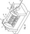
- FIG. 14an element 208 is illustrated that represents the path that guide wire 50 would extend through when the rotating assembly is in the load and unload position. When the rotating assembly is in the load and unload position the path represented by element 208 is in alignment with guide wire slits 84 in supporting blocks 92 and 94 that are illustrated in FIG. 9 .
- the rollers within the engagement surfaces of the four pairs of rollers 102, 104, 106, 108move toward one another to apply sufficient pressure to rotate guide wire 50 upon rotation of rotational drive mechanism 96 while still permitting guide wire 50 to be independently moved along its longitudinal axis by axial drive mechanism 48.
- the rotation of guide wire 50results from the torque imparted on guide wire 50 because of the frictional forces between four pairs of rollers 102, 104, 106, and 108 during rotation of rotational drive mechanism 96.
- the rollers in the pairs of rollers 102-108are free to rotate about their vertical axis allowing a guide wire 50 to move axially.
- y-connector 160is connected to a proximal end of guide catheter 144.
- Guide catheter 144has a central bore.
- Guide wire 50 and working catheter 54pass through y-connector 160 into central bore 174 of guide catheter 144 upon exiting cassette 24 through opening 172.
- guide catheter 144runs substantially parallel to rod 164 from y-connector 160 to guide catheter support 26, where it is releasably secured.
- Guide catheter support 26facilitates movement of guide wire 50 and working catheter 54 within central bore 174 of guide catheter 144, by helping to keep guide catheter 144 straight.
- Working catheter 54is placed in working catheter channel 138 between pair of rollers 136 of second axial drive mechanism 52. After positioning guide wire 50 and working catheter 54, cover 44 of cassette 24 is closed, again activating the engagement-disengagement mechanism. Robotic vascular catheter system 10 is loaded, drive mechanisms having releasably engaged guide wire 50 and working catheter 54.
- Each of the capstan socketsis configured to receive one of the capstans of motor drive base 302.
- base plate 318includes a hole or aperture aligned with each of the capstan sockets 310, 312, and 314 to allow each capstan to engage with the appropriate capstan socket.
- the engagement between the capstans and capstan socketsallows the transfer of energy (e.g., rotational movement) generated by one or more actuators (e.g., motors) located within motor drive base 302 to each of the drive mechanisms (discussed below) within cassette 300.
- a single actuatorprovides energy to each of the drive mechanisms.
- the positioning of the capstans and capstan socketshelps the user to align cassette 300 relative to motor drive base 302 by allowing cassette 300 to be mounted to motor drive base 302 only when all three capstan sockets are aligned with the proper capstan.
- Encoder assembly 454includes magnetic coupling 480 that engages a magnetic encoder located within motor drive base 302.
- the magnetic encoderis configured to measure an aspect (e.g., speed, position, acceleration, etc.) of axial movement of the working catheter.
- shaft 464rotates causing magnetic coupling 480 to rotate.
- the rotation of magnetic coupling 480causes rotation of the magnetic encoder within motor drive base 302.
- the magnetic encoder within motor drive base 302is able to provide a measurement of the amount of axial movement experienced by the working catheter during a procedure.
- This informationmay be used for a variety of purposes. For example, this information may be displayed to a user at workstation 14, may be used in a calculation of or estimated position of the working catheter within the vascular system of a patient, may trigger an alert or alarm indicating a problem with working catheter advancement, etc.
- FIG. 21shows a top view of axial drive assembly 324 in the "loading" configuration with handle 358 (shown in broken lines) rotated such that it is generally parallel to guide wire channel 364.
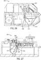
- FIG. 22shows a top view of axial drive assembly 324 in the "loaded” or “use” configuration with handle 358 rotated such that it is generally perpendicular to guide wire channel 364.
- handle 358is moved from the position of FIG. 22 to the position of FIG. 21 , the engagement surfaces of both guide wire axial drive mechanism 350 and working catheter axial drive mechanism 352 are moved away from each other increasing the space between the pairs of wheels in the drive mechanisms. This provides sufficient space between the wheels of each drive mechanism to allow the user to place guide wire 301 and working catheter 303 into the channels between the wheels.
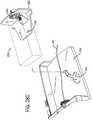
- collar 516extends through and is supported by journal 388 such that rear shaft 514 rotates within collar 516 as rotational drive mechanism 380 is rotated.
- Collar 516rests within a recess or slot formed within journal 388.
- rear shaft 514may be in direct contact with journal 388 such that rear shaft 514 rotates within the recess or slot of journal 388 as rotational drive mechanism 380 is rotated.
- Guide wire channel 390extends the length of chassis 382 through both front shaft 512 and rear shaft 514.
Landscapes
- Health & Medical Sciences (AREA)
- Life Sciences & Earth Sciences (AREA)
- Engineering & Computer Science (AREA)
- Animal Behavior & Ethology (AREA)
- Veterinary Medicine (AREA)
- Public Health (AREA)
- Biomedical Technology (AREA)
- Heart & Thoracic Surgery (AREA)
- General Health & Medical Sciences (AREA)
- Surgery (AREA)
- Anesthesiology (AREA)
- Pulmonology (AREA)
- Biophysics (AREA)
- Hematology (AREA)
- Medical Informatics (AREA)
- Molecular Biology (AREA)
- Nuclear Medicine, Radiotherapy & Molecular Imaging (AREA)
- Physics & Mathematics (AREA)
- Pathology (AREA)
- Oral & Maxillofacial Surgery (AREA)
- Electromagnetism (AREA)
- Robotics (AREA)
- Mechanical Engineering (AREA)
- Media Introduction/Drainage Providing Device (AREA)
Description
- The present invention relates generally to the field of robotic catheter systems for performing interventional procedures. One interventional procedure used to treat patients with diseased, often obstructed, heart arteries, is a percutaneous coronary intervention ("PCI").
- Before performing an interventional procedure with the disclosed invention, a diagnostic procedure is typically performed. An exemplary diagnostic procedure performed before performing a PCI may include a number of steps. Starting in the femoral artery, a 0.038 guide wire is run over the top of the aortic arch. A diagnostic catheter is advanced over the 0.038 guide wire after which the 0.038 guide wire is removed allowing the diagnostic catheter (DC) to return to its preformed shape enabling the DC to access either the left or the right ostium of the aorta. A contrast media is injected through the DC and the heart is x-rayed to identify the existence and location of any lesion. A y-connector may be secured to the end of the DC outside of the patient. The y-connector provides a means for introducing the contrast media or medication. The y-connector employs a one way valve both at the y-connector leg and the free open end. The 0.038 guide is then reinserted into the DC advanced over the top of the aortic arch, and the diagnostic catheter is removed. When the diagnostic is completed the 0.038 guide wire may be left in place for use in a PCI procedure.
- Document
US2006/041245 A1 describes a system for moving an elongate medical device having at least one drive element for engaging and moving an elongate medical device. The system provides for moving the separate inner and outer elements of a telescoping medical device. The system also provides for the rotation of a rotatable distal element on a rotatable medical device or the rotation of extension element in a telescoping medical device. - Document
US2007/239120 A1 shows a method of performing a medical procedure on a patient comprises conveying control signals from a remote controller to a drive unit, intravenously introducing the catheter into a heart of the patient (e.g., via the vena cava into the right atrium), and creating a puncture within a wall between two chambers (e.g., the left and right atria) of the heart. The method further comprises creating a puncture within a wall between two chambers of the heart, and operating the drive unit in accordance with the control signals to advance a working catheter within the guide catheter through the puncture. - Document
EP 1 442 720 A1 describes a remotely controllable robotic apparatus for the maneuvering of flexible catheters in the human cardiovascular system. The remotely controllable robotic apparatus comprises means in the form of an arm for the positioning, aiming and correct orientation with respect to the patient's body of a device which supports at least one portion of the catheter and which comprises remotely controllable actuators for transmitting to the said catheter at least a longitudinal movement of advance or withdrawal and/or a rightward or leftward rotary movement about its longitudinal axis, these actuators consisting of sets of opposing wheels or rollers parallel to each other, or equivalent means such as belts, connected to remotely controllable rotation means and positioned in such a way as to transmit the aforesaid movements to the catheter. - According to the invention, there is provided a robotic catheter system, the system comprising: a motor drive base comprising one or more drive motors located in the motor drive base; and a cassette configured to couple to the motor drive base, the cassette including a cassette housing, the cassette housing including a front end, a rear end, a first channel and a second channel, wherein the cassette includes: a first pair of engagement surfaces configured to releasably engage and impart axial movement to a guide wire retained in the first channel, wherein the guide wire extends out of a rear of the cassette housing and exits a front end of the cassette housing; and a second pair of engagement surfaces configured to releasably engage and impart axial movement to a catheter device retained in the second channel; wherein the catheter device exits the front end of the cassette housing over the guidewire; wherein the second channel is arranged at an angle with respect to the first channel.
- Disclosed is also a cassette for use with a robotic catheter system to couple to a base. The cassette includes a housing, a first axial drive mechanism supported by the housing configured to releasably engage and drive a guide wire along a longitudinal axis of the guide wire, and a second axial drive mechanism supported by the housing configured to releasably engage and drive a working catheter along a longitudinal axis of the working catheter. The cassette also includes a rotational drive mechanism supported by the housing configured to rotate the guide wire about its longitudinal axis. The rotational drive mechanism includes an engagement structure configured to releasably engage the guide wire, the engagement structure is configured to apply sufficient force to rotate the guide wire about its longitudinal axis while permitting the guide wire to be moved axially by the first drive mechanism. The first axial drive mechanism, the second axial drive mechanism, and the rotational drive mechanism are configured to be operatively coupled to at least one actuator that provides energy to drive the guide wire, to drive the working catheter, and to rotate the guide wire.
- Further is disclosed a robotic vascular catheter system comprising a user interface, a motor controller, a cassette base including a motor coupler at least one motor coupled to the motor coupler. A cassette is removably mounted to the cassette base and operatively coupled to the motor coupler. The cassette including a first axial drive mechanism configured to releasably engage and drive a guide wire along its longitudinal axis through a guide catheter. The cassette also including a second axial drive mechanism is configured to releasably engage and drive a working catheter along its longitudinal axis through a guide catheter. The cassette further including a first rotational drive mechanism is configured to releasably engage and rotate the guide wire about its longitudinal axis. The first rotational drive mechanism has a first grip surface and a second grip surface configured to releasably engage the guide wire. The first grip surface and the second grip surface configured to apply sufficient force to the guide wire to rotate the guide wire upon rotation of the rotational drive mechanism while still permitting the guide wire to be independently moved along its longitudinal axis by the first axial drive mechanism.
- Even further is disclosed a catheter drive cassette configured to couple to a motor drive base. The cassette includes a housing; a first axial drive mechanism is supported by the housing and configured to releasably engage and drive a guide wire along its longitudinal axis. A second axial drive mechanism is supported by the housing and configured to releasably engage and drive a working catheter along its longitudinal axis. A first rotational drive mechanism is configured to rotate the guide wire about its longitudinal axis. The first rotational drive mechanism includes a rotating structure configured to releasably engage the guide wire. The rotating structure is configured to apply sufficient force to rotate the guide wire about its longitudinal axis upon rotation of the rotating structure while still permitting the guide wire to be moved axially by the first axial drive mechanism. The first and second axial drive mechanisms and the rotational drive mechanism are connectable to a drive being external to the cassette.
- In the present specification, anything denoted embodiment or aspect and which does not fall under the scope of the appended claims shall be understood as illustrative examples. In particular is no method claimed.
FIG. 1 is a perspective view of the robotic vascular catheter system.FIG. 2 is a perspective view of the bedside system.FIG. 2a is the bedside system ofFIG. 2 with the cassette lid in an open position.FIG. 3 is a perspective view of the bedside system with the cassette removed from the motor drive base.FIG. 3A is a perspective view of the bottom of the cassette removed from the motor drive base.FIG. 4 is a view of a heart.FIG. 5 is a view illustrating the guide catheter, the guide wire, and the balloon catheter within the heart.FIG. 6 is a top view of the cassette.FIG. 7 is a cross section of the cassette when the y-connector is secure taken generally along line 7-7.FIG. 8 is a cross section of the cassette as shown inFIG. 7 when the y-connector is released.FIG. 9 is a perspective view of a portion of the cassette illustrating the rotational and axial drive systems.FIG. 10 is a cross sectional view of the axial drive system.FIG. 11 is a cross sectional view of the rotational drive taken generally about line 11-11 ofFIG. 6 .FIG. 12 is an alternative embodiment of a cassette system.FIG. 13 is a perspective view of a portion of the cassette with a guiding catheter support shown inFIG. 3 .FIG. 14 is a perspective view of a portion of the cassette with one embodiment of a rotating assembly.FIG. 15 is a perspective view of a bedside system showing another embodiment of a cassette prior to being attached to the motor drive base.FIG. 16 is a perspective view of a bedside system showing the cassette ofFIG. 15 following attachment to the motor drive base.FIG. 17 is a perspective view of a cassette in the "loading" configuration.FIG. 18 is a perspective view of a cassette in the "loaded" or "use" configuration.FIG. 19 is an exploded perspective view of an axial drive assembly of a cassette.FIG. 20 is a bottom perspective view of a cassette showing the base plate removed.FIG. 21 is a top view showing the axial drive assembly in the "disengaged" position.FIG. 22 is a top view showing the axial drive assembly in the "engaged" position.FIG. 23A is a top perspective view of a rotational drive assembly of a cassette showing the engagement structure in broken lines beneath the chassis.FIG. 23B is a top perspective view of a rotational drive assembly with the chassis shown in broken lines.FIG. 24 is a top view of the rotational drive assembly in the "engaged" position.FIG. 25 is a top view of the rotational drive assembly in the "disengaged" position.FIG. 26 is a sectional view of the rotational drive assembly taken generally along line 26-26 inFIG. 18 .FIG. 27 is a sectional view of the axial drive assembly taken generally along line 27-27 inFIG. 18 .FIG. 28A shows a rotational drive assembly coupled to a base plate of a cassette.FIG. 28B shows depression of a release button to disconnect the rotational drive assembly from the base plate of the cassette.FIG. 28C shows removal of the rotational drive assembly from the base plate of the cassette leaving the guide wire in place.- Referring to
FIG. 1 , a roboticvascular catheter system 10 is used for performing interventional procedures, including performing a percutaneous coronary intervention ("PCI"). Discussion will proceed assuming a PCI is being performed. It should be noted, however, one skilled in the art would recognize that, although the system described is configured to perform a PCI, it is capable of performing a number of interventional procedures with minor adjustments. For more complex procedures, more than one roboticvascular catheter system 10 may be used. - Robotic
vascular catheter system 10 comprises abedside system 12 andworkstation 14. Thebedside system 12 comprises a motor controller, an articulatingarm 18, anarm support 20, amotor drive base 22, acassette 24, and aguide catheter support 26. Guide catheter support may be part of the cassette or alternatively may be a separate component that can be mounted to the cassette.Bedside system 12 is in communication withworkstation 14, allowing signals generated by user inputs toworkstation 14 to be transmitted tobedside system 12, controlling the various functions of besidesystem 12.Bedside system 12 also may provide feedback signals toworkstation 14.Bedside system 12 may be connected toworkstation 14 with a wireless connection means (not shown), with cable connectors (not shown), or with any other means capable of allowing signals generated by user inputs toworkstation 14 to be transmitted to besidesystem 12. Workstation 14 is capable of being remotely located, enabling roboticvascular catheter system 10 users to perform procedures outside the radiation zone, for instance, in either a procedure room or a separate control room. One benefit of remotely locatingworkstation 14 is that the need to wear heavy lead garments may be eliminated. This reduces orthopedic occupational hazards, including, but not limited to, spinal injuries and general strain on the body of the operator. A second benefit of remotely locatingworkstation 14 is that the dangers associated with radiation exposure are reduced. A third benefit of remotely locatingworkstation 14 is that it allows users to multitask outside the procedure room during downtime.Bedside system 12 may be coupled to a standard table side bar (not shown) of a patient'sbed 28 by lockingbedside system 12 relative to apatient 30. The front ofbedside system 12, and correspondinglycassette 24, is the end nearest the head ofpatient 30 when a procedure is being performed. The back ofbedside system 12 is the end opposite the front. Coupling the bedside system to the bed or proximate the patient may be achieved using methods known in the art, including boltingbedside system 12 to the standard table side bar or using any other means sufficient to lockbedside system 12 relative topatient 30 and/or the bed. Ideallybedside system 12 is secured in a manner that is quick and easily to install.Bedside system 12 may be permanently coupled to the standard table side bar throughout numerous procedures, in oneembodiment cassette 24 is replaced for different patients and/or different PCI procedures. However,bedside system 12 may be removably coupled to a bed for movement from one bed to another.Cassette 24 is designed for a single use; it is disposable and should be replaced after each use.Cassette 24 may include a frangible component (not shown) that breaks off whencassette 24 is removed frommotor drive base 22 to help ensure thatcassette 24 is used for no more than a single use. Other mechanical means may be used to ensure a single use. For example, a portion of the cassette may be moved or manipulated in a way that does not permit the use of the cassette in another PCI procedure. Alternatively,cassette 24 may include an RFID (radio frequency identification) system (not shown) to identify when a cassette has been used. The cassette may include an RFID tag or other means of providing descriptive information identifying the type of cassette, particular features as well as a unique identifier for the particular cassette to distinguish it from any other cassette. Other components or systems capable of helping ensure thatcassette 24 is used for no more than a single use may also be alternatively used. The fact thatcassette 24 is designed for a single use has a number of benefits, including, but not limited to, helping maintain a sterility of roboticvascular catheter system 10 components and prevent patient-to-patient transmission of infections. The RFID system may permit the removal of the cassette for a short defined period of time, to enable resetting of the cassette, if it should fail to be securely attached in the first instance. The system could recognize the unique cassette by its unique identification from the RFID signal and allow the same cassette to be reintroduced only within a very short window of time that would suggest the cassette was being repositioned and not being used for another patient. It is also possible that the cassette may formed from materials that can be sterilized and reused, or certain components may be replaced that come into contact with bodily fluids.FIG. 2 illustrates a preferred embodiment of roboticvascular catheter system 10. Articulatingarm 18 is coupled to and protrudes outward fromarm support 20.Motor drive base 22 is coupled to articulatingarm 18.Cassette 24 is coupled to the top ofmotor drive base 22.- Articulating
arm 18 is configured to be locked into infinite positions relative topatient 30. In a preferred embodiment, articulatingarm 18 includes afirst knuckle 32 and asecond knuckle 34.First knuckle 32 enables articulatingarm 18 to pivot about a vertical axis and or a horizontal axis.Second knuckle 34 enables articulatingarm 18 to pivot up and down or about a horizontal axis. Articulatingarm 18 may have multiple degrees of freedom to positioncassette 24 in any orientation relative to the patient for proper positioning. Once the user has adjusted articulatingarm 18, articulatingarm 18 is locked into place by an articulating arm locking mechanism, preventing unwanted movement during the procedure. Articulating arm locking mechanism may be locked and unlocked mechanically, using a solenoid, or using any other mechanism capable of locking articulatingarm 18, along withmotor drive base 22 andcassette 24, relative topatient 30. - Referring to
FIG. 3 ,bedside system 12 illustrated inFIG. 2 is shown beforecassette 24 is attached tomotor drive base 22.Motor drive base 22 includes ahousing 38 and a plurality ofcapstans 40.Capstans 40 extend vertically to facilitate alignment withcassette 24 when couplingmotor drive base 22 andcassette 24.Cassette 24 includes ahousing 42, acover 44 pivotally attached tohousing 42, and a plurality ofcapstan sockets 46 corresponding tocapstans 40 onmotor drive base 22 to facilitate alignment withmotor drive base 22 when couplingcassette 24 andmotor drive base 22. In one embodiment capstans 40 extend generally upward and are matingly received incapstan sockets 46 that are located on the bottom surface ofcassette 24. This permitscassette 24 to be placed ontomotor drive base 22 in a generally downwardly direction. It is contemplated thatmotor drive base 22 andcassette 24 will be at an angle relative to a horizontal plane in an operative position to direct the guide catheter, guide wire and working catheter in a downwardly sloping direction toward the patient. Capstans 40 andcapstan sockets 46 are one embodiment of a motor coupler, coupling the motors to axial and rotation drive mechanisms in the cassette. Thecapstans 40 andcapstan sockets 46 may have gearing to allow a rotational force to be transmitted from motors located in themotor drive base 22 to the axial and rotational drive mechanisms within the cassette. While the capstans and capstan sockets allow the cassette to be placed downwardly onto the motor drive base, other motor couplers that can couple the motors to the drive mechanisms are also contemplated. In one embodiment the motors are located in themotor drive base 22. However, themotor drive base 22 may also be used to transmit force from motors located away from the motor drive base that are operatively coupled to the motor drive base with a mechanical linkage such as a cable or other mechanical coupler. It is also contemplated that the mechanical linkage could directly connect the motors to the capstan sockets so that themotor drive base 22 provides support for thecassette 24 and permits coupling of the cassette capstan sockets to the motors. - As illustrated in
FIG. 2A , cover 44 may be opened to provide access to the mechanisms withincassette 24 to help facilitate loading and unloading of the guide wire and catheter instruments within thecassette 24.Cover 44 may include a wall member used to help positively locate the guide wire within the transmission mechanisms as described more fully below.Cover 44 may be secured by a hinge or other pivot enabling members. Alternatively, cover 44 may be secured in an up down arrangement. The movement ofcover 44 from a closed to open position may cause the release of the guide wire or other catheter instruments from the transmission mechanisms. - Before coupling
cassette 24 tomotor drive base 22, a sterile, plastic cover (not shown) is draped over articulatingarm 18 andmotor drive base 22. The sterile, plastic cover includes pre-cut holes (not shown) that correspond to capstans 40 onmotor drive base 22. The sterile, plastic cover shields the sterilized components of roboticvascular catheter system 10 from the unsterilized components, includingmotor drive base 22, articulatingarm 18, andarm support 20.Cassette 24 is sterile before use. Oncecassette 24 has been coupled tomotor drive base 22 and used, it is disposed of and replaced with another sterile, single-use cassette. - Referring to
FIGS. 6 - 9 ,cassette 24 further includes a firstaxial drive mechanism 48 for driving aguide wire 50 along its longitudinal axis, a secondaxial drive mechanism 52 for driving a workingcatheter 54 along its longitudinal axis, a firstrotational drive mechanism 56 enablingguide wire 50 to rotate while still permittingguide wire 50 to be independently moved along its longitudinal axis. Workingcatheter 54 may be embodied as a balloon, stent on a delivery catheter, a stent with a balloon, or any other therapeutic or diagnostic catheter device; these embodiments are collectively referred to as workingcatheter 54. In one embodiment firstaxial drive mechanism 48 and firstrotational drive mechanism 56 are positioned substantially in series along alongitudinal axis 60 ofcassette 24. In one embodiment, secondaxial drive mechanism 52 is positioned at an angle to firstaxial drive mechanism 48. - After coupling
cassette 24 tomotor drive base 22 and before using roboticvascular catheter system 10 for a procedure,guide wire 50 and workingcatheter 54 must be loaded into the drive mechanisms incassette 24. To loadcassette 24, the user openscover 44. Upon openingcover 44, an engagement-disengagement mechanism is activated, causing the drive mechanisms to automatically adjust for quick access. Whencassette 24 is in open cover position, the drive mechanisms are in position for loadingguide wire 50 and workingcatheter 54. Upon closingcover 44, the engagement-disengagement mechanism is activated, causing the drive mechanisms to automatically adjust, releasably engagingguide wire 50 and workingcatheter 54. Alternatively, it may be possible to engage and/or disengageguide wire 50 whencover 44 is in an open position. Whencassette 24 is in closed cover position, the drive mechanisms apply sufficient pressure to guidewire 50 and workingcatheter 54 to be able to drive them. In a preferred embodiment, cover 44 is formed from a clear, translucent material to permit viewing of the drive mechanisms whilecover 44 is closed, in closed cover position. Though, one of skill in the art would recognize that a variety of other materials are suitable. It may also be possible to disengage the drive mechanisms with a mechanical switch or electromechanical device with or without first opening the cover. Disengagement of the drive mechanisms will result in the surfaces of the pinch rollers of the axial drive mechanisms and the engagement surfaces of the rotational drive mechanism moving away from one another to allow easy removal and insertion of the guide wire and working catheter. At least one of the pinch rollers is supported by at least one disengagement mechanism that physically moves the pinch roller surfaces away from one another. Similarly, the engagement surfaces of the rotational drive mechanism are also operatively connected to a disengagement mechanism to physically move the engagement surfaces of the rotational drive mechanism away from one another. The pinch rollers are in a disengagement position when the pinch roller surfaces are positioned apart from one another. Cassette 24 further includes a system to self-test the cassette upon loading (not shown). The system for self-testing cassette loading may be activated by an operator atworkstation 14. Alternatively, the system may automatically initiate a self-test of the cassette upon closing ofcover 44 to test each of the drive mechanisms. Feedback from the motors toworkstation 14 could confirm proper seating of the cassette within the base. In addition to testing that each of the motors are properly secured to the cassette, each transmission mechanism may be activated to move the guide wire and/or working catheter a predetermined distance or rotation and then measure the distance actually moved or rotated by use of sensors. If the movement conforms to the predetermined parameters the system is shown to be working and operational. When the detected movement of the guide wire and/or working catheter does not conform to set parameters the system will show an error message.Cassette 24 is designed with ergonomic considerations in mind, handle 64 enables easy manipulation and movement of the cassette and cassette base by an operator to position the system relative to the patient.Cover 44 may include alatch 210 located on the inside surface of the cover or in within the housing of the cassette to holdguide wire 50 during exchanges or when manipulating more than one wire.Catheter system 10 may include system for inflating workingcatheter 54, and a system for injecting a contrast media. Specifically,work station 14 may include a control mechanism for remotely controlling a pump for the injection of a contrast media.- Referring to
FIG. 9 cassette 24 is shown withoutcover 44 and withouthousing 42.Cassette 24 includes abase plate 70 that supports firstaxial drive mechanism 48 and firstrotational drive mechanism 56.Axial drive mechanism 48 androtational drive mechanism 56 are positioned and secured consecutively/in series along a longitudinal axis ofbase plate 70. Firstaxial drive mechanism 48 is shown positioned closer to the back end ofcassette 24, behind firstrotational drive mechanism 56. It should be noted, however, that firstrotational drive mechanism 56 may be positioned behind firstaxial drive mechanism 48. It is believed that positioningrotational drive mechanism 56 closer to the patient provides for increased control of rotation of the guide wire, since any pressure and/or friction from the rollers inaxial drive mechanism 48 is located distal the patient. - Referring to
FIG. 9 and10 , firstaxial drive mechanism 48 includes afirst roller 72 and asecond roller 74 working in cooperation to driveguide wire 50 in an axial direction.First roller 72 is spring biased towardsecond roller 74 with sufficient force to provide movement to guidewire 50 upon rotation ofrollers guide wire 50 about its axis. In one embodimentfirst roller 72 has a first engagement surface andsecond roller 74 includes a second engagement surface.Guide wire 50 is removably placed between the first and second engagement surfaces of the first andsecond rollers second rollers guide wire 50 to effectively permit translation of the guide wire along its longitudinal axis upon rotation of at least one of the rollers. Second roller 74 is driven by a drive gear orroller 76 via abelt 78. Sufficient tension is applied to belt 78 via atension member 80. However,second roller 74 may be driven directly from one of thecapstans 40 inmotor drive base 22.- In alternative embodiments, pair of
rollers guide wire 50 along its longitudinal axis. - Further referring to
FIGS. 6 ,9 and11 , firstrotational drive mechanism 56 includes a first rotational drivemechanism supporting block 92, a second rotational drivemechanism supporting block 94, and arotational drive mechanism 96.Rotational drive mechanism 96 includes aplate 100, four pairs ofrollers roller fasteners roller axles longitudinal axis 128, and a pair ofcylindrical protrusions 130 that extend through and are supported in a bore in each of supportingblocks cylindrical protrusions rotational drive mechanism 96, extending outward from either end ofrotational drive mechanism 96 along itslongitudinal axis 128. First rotational drivemechanism supporting block 92 and second rotational drivemechanism supporting block 94 are transverse tolongitudinal axis 128 ofbase plate 70 and are spaced out along the longitudinal axis of base plate 70 a distance sufficient to accommodaterotational drive mechanism 96 between them.Rotational drive mechanism 96 is suspended and secured between first rotational drivemechanism supporting block 92 and second rotational drivemechanism supporting block 94 overbase plate 70 by pair ofcylindrical protrusions guide wire 50 to extend. Referring toFIG. 14 the elements ofrotational drive mechanism 96 may be supported on arotating assembly 206 that rotates between supportingblocks - Each supporting
block longitudinal axis 128 ofrotational drive mechanism 96. Each of the four pairs ofrollers rotational drive mechanism 96. Four pairs ofrollers roller fasteners axles roller fasteners rollers axles FIG. 14 anelement 208 is illustrated that represents the path that guidewire 50 would extend through when the rotating assembly is in the load and unload position. When the rotating assembly is in the load and unload position the path represented byelement 208 is in alignment with guide wire slits 84 in supportingblocks FIG. 9 . - When
cover 44 ofcassette 24 is in the closed position, a rotational drive mechanism locator may be used to assist in the positioning ofguide wire 50 downward toward the longitudinal axis ofrotational drive mechanism 96 to help locate and maintainguide wire 50 between the four pairs ofrollers Guide wire 50 is releasably engaged between four pairs ofrollers rotational drive mechanism 56. When roboticvascular catheter system 10 is used during a procedure, the rollers within the engagement surfaces of the four pairs ofrollers guide wire 50 upon rotation ofrotational drive mechanism 96 while still permittingguide wire 50 to be independently moved along its longitudinal axis byaxial drive mechanism 48. The rotation ofguide wire 50 results from the torque imparted onguide wire 50 because of the frictional forces between four pairs ofrollers rotational drive mechanism 96. The rollers in the pairs of rollers 102-108 are free to rotate about their vertical axis allowing aguide wire 50 to move axially. The pressure between each pair of rollers is sufficient to impart a rotation to aguide wire 50 located therebetween when the entire rotational drive mechanism is rotated. The rollers may be moved away from one another to permit easy insertion and removal ofguide wire 50 to load and unload the guide wire within the rotational drive mechanism. One set of the rollers may be moved away from the other set of rollers whencover 44 is in the open position and allowed to move back toward the other set of rollers whencover 44 is in a closed position. In order to easily remove or insertguide wire 50 intorotational drive mechanism 96 between the rollers avertical path 98 must align with guide wire slit 84. Whencover 44 is opened, the rotational drive mechanism rotates to a load/unload position in whichvertical path 98 is aligned with guide wire slit 84 thereby allowing easy insertion and/or removal ofguide wire 50 from the rotational drive mechanism. Alternatively, the rollers do not move away from one another but allow for manual insertion and removal ofguide wire 50 between the rollers. The manual insertion may be permitted by the flexibility of the rollers themselves or by permitting one of the spring biased rollers to move away from the second in the pair of rollers to allow insertion ofguide wire 50. - Alternative embodiments of four pairs of
rollers rollers guide wire 50 upon rotation ofrotational drive mechanism 96 while still permittingguide wire 50 to be independently moved along its longitudinal axis. Similarly, four pairs ofrollers guide wire 50 upon rotation ofrotational drive mechanism 96 while still permittingguide wire 50 to be independently moved along its longitudinal axis. In another embodiment rotational drive mechanism may include two engagement surfaces that may or may not rotate in the axial direction of the longitudinal axis of the guide wire. - When
cover 44 ofcassette 24 is in open cover position, firstaxial drive mechanism 48 and firstrotational drive mechanism 56 are positioned such to facilitateloading guide wire 50 and workingcatheter 54. In the insertion and removal position, guide wire slits 84 in supportingblocks guide wire path 98 ofrotational drive mechanism 96 are substantially aligned. Similarly, pair ofrollers axial drive mechanism 48 and four pairs ofrollers rotational drive mechanism 56 are substantially aligned. This enablesguide wire 50 to extend through both firstaxial drive mechanism 48 and firstrotational drive mechanism 56. As discussed above, each of the pair of rollers in the axial drive mechanism and rotational drive mechanism may move apart to facilitate easy insertion and removal ofguide wire 50 whencover 44 is in the open position. - Further referring to
FIG. 6 secondaxial drive mechanism 52 comprises a pair ofrollers 136, and a workingcatheter channel 138. Pair ofrollers 136 releasably engage workingcatheter 54 in workingcatheter channel 138. Whencassette 24 is in open cover position, secondaxial drive mechanism 52 is positioned such to facilitateloading working catheter 54 between pair ofrollers 136. Whencover 44 ofcassette 24 is closed, workingcatheter 54 is loaded and releasably engaged between pair ofrollers 136. Alternate embodiments of secondaxial drive mechanism 52 include, but are not limited to, an embodiment wherein pair ofrollers 136 comprises a roller and an anvil or a roller and any grip surface wherein the pressure between that grip surface and a roller is sufficient to drive workingcatheter 54 along its longitudinal axis. Other axial drive mechanisms are also contemplated and may be used. - Referring to
FIG. 1 workstation 14 comprises auser interface 142.User interface 142 enables a user to enter commands controlling the axial motion ofguide wire 50 via firstaxial drive mechanism 48, the axial motion of workingcatheter 54 via secondaxial drive mechanism 52, and the rotational motion ofguide wire 50 via firstrotational drive mechanism 56. In an alternative embodiment of roboticvascular catheter system 10, the user would additionally be capable of controlling aguide catheter 144 fromworkstation 14, in an axial and/or rotational manner. - In a preferred embodiment,
user interface 142 includes afirst screen 146 and asecond screen 148.First screen 146 andsecond screen 148 are configured to present information and images potentially useful to a user of roboticvascular catheter system 10.User interface 142 further includes atouch screen 150, having a pair ofjoysticks 152 having variable speed control, afirst jog button 154 for 1 mm jogs, and asecond jog button 156 for 5 mm jogs.First jog button 154 andsecond jog button 156 have continuous jog capability. Depression of the jog buttons will move the guide wire 50 a set distance forward. Jog buttons may be used for movement ofguide wire 50 and/or workingcatheter 54. Rotational Jog button may be set to rotate a pre-set degree or it may be set to rotate a selected degree. Another button may be used to accelerate the speed of theguide wire 50 or provide a multiplier so that the variable speed control reacts in a heightened manner. For example if movement of a joystick a set distance results in the movement of the guide wire at a set speed in normal operation, the guide wire would move at a multiple of the set speed by depressing the button to accelerate the speed. - In alternative embodiments,
user interface 142 may have various configurations. For instance,touch screen 150 may be integrated with x-ray or other imaging data. In fact, a variety of data and controls may be integrated on a single screen, including, but not limited to, contrast media insertion control, balloon inflation control, image processing control(s), hemodynamic data, etc. Alternative joystick configurations include, but are not limited to separate joysticks may be provided for each drive mechanism, rather than two joysticks for controlling all drive mechanisms. - Robotic
vascular catheter system 10 may further incorporate a number of safety features and conveniences (not shown). For instance, roboticvascular catheter system 10 may be capable of providing a mechanism for a user to manually override it during a procedure. In the event, that the operator must manually align the rotational drive mechanism to remove theguide wire 50, it is contemplated that the rotational drive mechanism can be moved to a load unload position so that the engagement surfaces in the rotational drive mechanism are separated and in line with the slits in rotational drive mechanism supports. Additionally,workstation 14 may incorporate a system allowing a user to voice-activate controls, a feature which could be overridden by an emergency stop. There may also be a force limitation mechanism. Roboticvascular catheter system 10 could have a pre-determined limit to the amount of force that could be placed onguide wire 50. If the motors were to apply a force greater than the pre-determined amount, a clutch act to disengage the wheels from the motors. For example if any of the drive mechanisms were to become stuck and unable to rotate a clutch mechanism would act to allow the motors to rotate without causing damage to the stuck drive mechanism or the motor itself. - Another possible feature is a slippage-detecting mechanism. Such a mechanism would provide a continuous check between the desired and actual movements of
guide wire 50 or workingcatheter 54 and rollers, pair ofrollers axial drive mechanism 48 and four pairs ofrollers rotational drive mechanism 56. This mechanism could provide warnings when a given threshold has been crossed. This threshold may remain constant throughout a procedure or may vary depending on the location of system components in the heart. In one embodiment, an ancillary encoder (not shown) may be used to give the exact location ofguide wire 50, in terms of both axial and rotational movement, and workingcatheter 54, in terms of axial movement, during a procedure. Pair ofrollers rollers idler rollers 158 that check the movement of the roboticvascular catheter system 10, comparing the movement of the rollers to motor movement. Note that these features and conveniences are exemplary and should not be read to be exhaustive. - Referring to
FIGS. 3 ,7 ,8 and13 in apreferred embodiment cassette 24 further includes acoupling mechanism 162 for securing a y-connector 160 attached to aguide catheter 144 and a guide catheter support arm, shown as arod 164.Coupling mechanism 162 releasably secures y-connector 160. Y-connector 160 connects to guidecatheter 144. Y-connector 160 further provides a means for administering drugs to a patient during the PCI procedure. In one embodiment, roboticvascular catheter system 10 provides a user the ability to remotely control drug administration through y-connector 160.Guide catheter 144 may be able to pivot about its longitudinal axis independent of y-connector 160. The y-connector includes three legs. A first leg is attached to theguide catheter 144. A second leg is angled away from the longitudinal axis of the guide catheter to permit introduction of a contrast agent or medicine. A one way valve prohibits bodily fluid from exiting the second leg. A third leg extends away from the guide catheter and allows insertion of a working catheter and guide wire through the y-connector. The third leg also includes a one way valve that permits insertion and removal of the working catheter and guide wire but prohibits bodily fluids from exiting the third leg. - A
rod 164 is coupled tocassette 24 at a point along the front end ofcassette 24 and supports guidecatheter support 26 at its other end.Rod 164 is adjustable, and capable of translating away fromcassette 24 and back towardscassette 24 and moving independently ofcassette 24, to help position guidecatheter 24 using methods known in the art. In alternative embodiments,rod 164 may take on any number of configurations capable of supportingguide catheter support 26 and guidecatheter 144. For example, guiderod 164 may include telescoping segments. Guide catheter support 26, shown as a spring-loaded clamp, provides support forguide catheter 144.Guide catheter support 26 is at a point between the front end ofcassette 24 andpatient 30 during a procedure. In this position, guidecatheter support 26 helps prevent unwanted movement of theguide catheter 144 and its contents, affording greater accuracy when performing a procedure.- Referring to
FIG. 6 , whenguide wire 50 and workingcatheter 54 have been loaded in roboticvascular catheter system 10, cover 44 ofcassette 24 is closedguide wire 50 extends out of the back end ofcassette 24 through an opening inhousing 42. Moving toward the front end ofcassette 24,guide wire 50 passes through firstaxial drive mechanism 48, through firstrotational drive mechanism 56, and then converges with workingcatheter 54 at aconvergence zone 166. Workingcatheter 54 enterscassette 24 through aslot 168 in the side ofhousing 42. Before converging withguide wire 50 atconvergence zone 166, workingcatheter 54 first passes through secondaxial drive mechanism 52. Workingcatheter 54 includes a hollow over the wire portion, which guidewire 50 passes into atconvergence zone 166. Workingcatheter 54 withguide wire 50 in its over the wire portion exits the front end ofcassette 24 through anopening 172.Cassette 24 may include a channel configured to constrain the working catheter along a predefined path from a first point where the longitudinal axis of the working catheter and the longitudinal axis of the guide wire are not coaxial to a point where the longitudinal axis of the working catheter and the longitudinal axis of the guiding catheter are co-axial. The path is located within the housing and may include a groove or other physical means to form at least a portion of the path. - Further referring to
FIG. 6 , y-connector 160 is connected to a proximal end ofguide catheter 144.Guide catheter 144 has a central bore.Guide wire 50 and workingcatheter 54 pass through y-connector 160 intocentral bore 174 ofguide catheter 144 upon exitingcassette 24 throughopening 172. In a preferred embodiment, guidecatheter 144 runs substantially parallel torod 164 from y-connector 160 to guidecatheter support 26, where it is releasably secured.Guide catheter support 26 facilitates movement ofguide wire 50 and workingcatheter 54 withincentral bore 174 ofguide catheter 144, by helping to keepguide catheter 144 straight. - Y-
connector 160 is releasably secured tocassette 24 bycoupling mechanism 162, shown in a preferred embodiment as a spring-biased clamp inFIGS. 7 and 8 .Coupling mechanism 162 includes aframe 176, ahandle 178, and at least onespring 180.Frame 176 includes a receivingportion 182 against which y-connector 160 is secured. Handle 178 includes alever arm 184 and acapture portion 186.Capture portion 186 applies sufficient pressure to secure y-connector 160 against receivingportion 182 offrame 176 whenlever arm 184 is not depressed. Handle 178 pivots about apivot point 188.Springs 180 exert an upward force onlever arm 184 at a distance frompivot point 188, biasingcapture portion 186 ofhandle 178 toward receivingportion 182 offrame 176. Referring toFIG. 8 , whenlever arm 184 is depressed, springs 180 are also compressed.Capture portion 186 ofhandle 178 pivots aboutpivot point 188, moving away from y-connector 160 and receivingportion 182 and releasing y-connector 160. Referring back toFIG. 7 , whenhandle 178 is releasedlever arm 184 is again forced upward, pivoting aboutpivot point 188.Capture portion 186 moves in toward receivingportion 182 and y-connector 160, releasably securing y-connector 160. - The exemplary procedure begins after a diagnostic procedure has been completed, leaving a diagnostic guide wire (not shown) in a heart 190 (shown in
FIG. 4 ),heart 190 including anaorta 192 and anaortic arch 194. Before using roboticvascular catheter system 10,guide catheter 144 is run up intoaorta 192 over the diagnostic guide wire, the diagnostic guide wire is removed, and guidecatheter 144 is positioned into either aright ostium 196 opening to the right coronary artery or aleft ostium 198 opening to the circumflex or left anterior descending arteries, depending where alesion 200 is located. The shape ofguide catheter 144 varies based on which ostium it is to enter. As discussed above,bedside system 12 is likely already fixed to patient'sbed 28. - For the purposes of clarity, steps for advancing
guide catheter 50 and workingcatheter 54 andloading bedside system 12 will be discussed separately and in turn. One of skill in the art would recognize that a number of the steps in the discussion are interchangeable without deviating significantly from the example method. Guide catheter 144 is attached to y-connector 160. A y-connector introducer (not shown) is placed into y-connector 160.Guide wire 50 is advanced through the y-connector introducer intoguide catheter 144 and then removed. Workingcatheter 54 is loaded ontoguide wire 50. Workingcatheter 54 is then manually advanced up intoguide catheter 144 overguide wire 50 until it is near the free end ofguide wire 50.Cassette 24 is coupled tomotor drive base 22 over the sterile, plastic cover. Articulatingarm 18 is locked relative topatient 30 and cover 44 ofcassette 24 is opened, activating engagement-disengagement mechanism, which causes the drive mechanisms to position for loadingguide wire 50 and workingcatheter 54.Guide wire 50 is positioned intoguide wire path 98 between four pairs ofrollers rotational drive mechanism 56, and into guide wire slit 84 and pair ofrollers axial drive mechanism 48. The back end ofguide wire 50 extends outwardly through the back ofhousing 42 and may contain a guide wire holder or support to contain the length of guide wire not being used within the patient. Workingcatheter 54 is placed in workingcatheter channel 138 between pair ofrollers 136 of secondaxial drive mechanism 52. After positioningguide wire 50 and workingcatheter 54, cover 44 ofcassette 24 is closed, again activating the engagement-disengagement mechanism. Roboticvascular catheter system 10 is loaded, drive mechanisms having releasably engagedguide wire 50 and workingcatheter 54.- Y-
connector 160 is releasably secured tocassette 24 by depressinghandle 178, placing y-connector 160 betweenframe 176 and handle 178. In this manner guidecatheter 144 is releasably secured to thecassette 24. - The user operates the controls at
workstation 14. In the above-discussed preferred embodiment ofworkstation 14,touch screen 150, a pair ofjoysticks 152, afirst jog button 154, and asecond jog button 156 are operated to direct the motion ofguide wire 50 and workingcatheter 54. As shown inFIG. 5 ,guide wire 50 is typically moved and then followed by workingcatheter 54 untilguide wire 50 is moved acrosslesion 200. Onceguide wire 50 has crossedlesion 200, workingcatheter 54 is driven across, often fine tuning the position usingfirst jog button 154,second jog button 156, or a combination of both. - Referring to
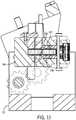
FIG. 12 , an alternativeaxial drive 212 member may be used. For example pinch rollers may be replaced with a two belt mechanism. - Referring to
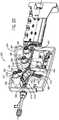
FIG. 13 ,cassette 24 includes aguide catheter support 202. Y-connector coupling mechanism is supported byguide catheter support 202. In an alternative embodiment, guidecatheter support 202 may include asled 204 that can be moved in a fore aft direction so that the guide catheter may be moved in a direction along its longitudinal axis.Cassette 24 may also include a drive mechanism to rotatesled 204 such that the guide catheter is rotated about its longitudinal axis, and a drive mechanism to movesled 204 in the fore aft direction such that the guide catheter may be moved along the longitudinal axis of the guide wire. The drive mechanisms used to movesled 204 may be located in themotor drive base 22 and move thesled 204 relative tocassette 24, so thatsled 204 may be moved independently of the guide wire and/or working catheter. - Referring now to
FIGS. 15 through 28C , another exemplary embodiment of a cassette for use with a robotic catheter system is shown. Similar to the embodiment discussed above,cassette 300 may be equipped with aguide wire 301 and a workingcatheter 303 to allow a user to perform a catheterizationprocedure utilizing cassette 300. In this embodiment,bedside system 12 includes acassette 300 configured to be mounted to amotor drive base 302.FIG. 15 shows a bottom perspective view ofcassette 300 prior to mounting tomotor drive base 302.Motor drive base 302 includes afirst capstan 304, asecond capstan 306, and athird capstan 308, andcassette 300 includes afirst capstan socket 310, asecond capstan socket 312, and athird capstan socket 314.Cassette 300 includes ahousing 316, andhousing 316 includes abase plate 318. - Each of the capstan sockets is configured to receive one of the capstans of
motor drive base 302. In the embodiment shown,base plate 318 includes a hole or aperture aligned with each of thecapstan sockets motor drive base 302 to each of the drive mechanisms (discussed below) withincassette 300. In one embodiment, a single actuator provides energy to each of the drive mechanisms. In another embodiment, there is an actuator that drivescapstan 304, an actuator that drivescapstan 306, and an actuator that drivescapstan 308. Further, the positioning of the capstans and capstan sockets helps the user to aligncassette 300 relative tomotor drive base 302 by allowingcassette 300 to be mounted tomotor drive base 302 only when all three capstan sockets are aligned with the proper capstan. - In one embodiment, the motors that drive
capstans motor drive base 302. In another embodiment, the motors that drivecapstans base 302 connected tocassette 300 via an appropriate transmission device (e.g., shaft, cable, etc.). In yet another embodiment,cassette 300 includes motors located within the housing ofcassette 300. In another embodiment,cassette 300 does not includecapstan sockets cassette 300 via alternating or rotating magnets or magnetic fields located withinmotor drive base 302. - In the embodiment shown,
cassette 300 also includes aguide catheter support 311 that supportsguide catheter 317 at a position spaced fromcassette 300. As shown, guidecatheter support 311 is attached tocassette 300 by arod 313.Rod 313 and guidecatheter support 311 are strong enough to supportguide catheter 317 without buckling.Guide catheter support 311 supports guidecatheter 317 at a position spaced from the cassette, between the patient and the cassette to prevent buckling, bending, etc. of the portion ofguide catheter 317 between the cassette and the patient. - Referring to
FIG. 16 ,cassette 300 is shown mounted tomotor drive base 302. As shown inFIG. 16 ,cassette 300 includes anouter cassette cover 320 that may be attached tohousing 316. When attached tohousing 316,outer cassette cover 320 is positioned over and covers each of the drive mechanisms ofcassette 300. By covering the drive assemblies ofcassette 300,outer cassette cover 320 acts to prevent accidental contact with the drive mechanisms ofcassette 300 while in use. - Referring to
FIG. 17 ,cassette 300 is shown in the "loading" configuration withouter cassette cover 320 removed.Cassette 300 includes a y-connector support assembly 322, anaxial drive assembly 324, and arotational drive assembly 326. Generally, the various portions ofcassette 300 are placed in the loading configuration to allow the user to load or install a guide wire and/or working catheter intocassette 300. Further, in the exemplary embodiment shown, y-connector support assembly 322 is located in front ofaxial drive assembly 324, andaxial drive assembly 324 is located in front ofrotational drive assembly 326 withincassette 300. - Y-
connector support assembly 322 includes achassis 328 and a y-connector restraint 330.Base plate 318 includes asupport arm 332 that supports y-connector support assembly 322.Chassis 328 is coupled to the front ofsupport arm 332 viapin connection 334. - A central groove or
depression 336 extends the length ofchassis 328. Y-connector 338 rests withincentral groove 336 ofchassis 328. Y-connector 338 includes afirst leg 340, asecond leg 342, and athird leg 344.First leg 340 is configured to attach to a guide catheter such that the central lumen of the y-connector is in fluid communication with the central lumen of the guide catheter.Second leg 342 is angled away from the longitudinal axis of y-connector 338.Second leg 342 of y-connector 338 allows introduction of a contrast agent or medicine into the lumen of the guide catheter. A one way valve prohibits bodily fluid from exitingsecond leg 342.Third leg 344 extends away from the guide catheter towardaxial drive assembly 324. In use,guide wire 301 and workingcatheter 303 are inserted intothird leg 344 of y-connector 338 viaopening 346 and may be advanced through y-connector 338 into the lumen of the guide catheter. The third leg also includes a one way valve that permits insertion and removal of the working catheter and guide wire but prohibits bodily fluids from exitingthird leg 344. Chassis 328 is rotatable about an axis defined bypin connection 334 to allowchassis 328 to be placed in the "loading position" shown inFIG. 17 . In the loading position,chassis 328 is positioned at about a 45 degree angle, shown byangle line 315, relative to supportarm 332.Chassis 328 is moved to the "loading position" to provide easier access to opening 346 of thethird leg 344 allowing the user to feedguide wire 301 and workingcatheter 303 into y-connector 338.- Y-
connector support assembly 322 includes y-connector restraint 330. Y-connector restraint 330 is configured to releasably engage y-connector 338. In the engaged position shown inFIG. 17 ,engagement arm 348 of y-connector restraint 330 engages or presses y-connector 338 intocentral groove 336 to securely hold y-connector 338. Y-connector restraint 330 may be moved to a disengaged position to release y-connector 338 fromchassis 328. Cassette 300 also includes anaxial drive assembly 324.Axial drive assembly 324 includes a first axial drive mechanism, shown as guide wireaxial drive mechanism 350, and a second axial drive mechanism, shown as working catheteraxial drive mechanism 352.Axial drive assembly 324 also includes atop deck 354, acover 356, and a latch or handle 358.- Generally, guide wire
axial drive mechanism 350 is configured to releasably engage and drive (e.g., to impart motion to)guide wire 301 along its longitudinal axis. In this manner, guide wireaxial drive mechanism 350 provides for advancement and/or retraction ofguide wire 301. Working catheteraxial drive mechanism 352 is configured to releasably engage and drive (e.g., to impart motion to) workingcatheter 303 along its longitudinal axis. In this manner, working catheteraxial drive mechanism 352 provides for advancement and/or retraction of workingcatheter 303. Top deck 354 is mounted to acentral portion 360 ofbase plate 318.Top deck 354 includes aguide wire channel 364 and a workingcatheter channel 366.Guide wire channel 364 is positioned generally perpendicular to the top surface oftop deck 354 and runs the length oftop deck 354 in the longitudinal direction. Workingcatheter channel 366 is positioned generally perpendicular to the top surface oftop deck 354 and is located at an angle relative to guidewire channel 364. A plurality oftabs 368 extend vertically from the top surface oftop deck 354 alongguide wire channel 364.- In
FIG. 17 ,cover 356 is shown in the open position. Handle 358 is moved to a position generally parallel to the longitudinal axis ofcassette 300 to allowcover 356 to move to the open position. Cover 356 is mounted totop deck 354 via hinges 370.Cassette 300 includes a restraint structure that acts to restrain movement of the guide wire whencover 356 is in the closed position. As shown, the restraint structure includes a plurality oftabs 372 extending from the lower surface ofcover 356.Tabs 372 are positioned such that whencover 356 is closed,tabs 372 are positioned within a portion ofguide wire channel 364 betweentabs 368 such thattabs 372 restrain movement ofguide wire 301 in a vertical direction (i.e., restrains movement of the guide wire in a direction perpendicular to the top surface of top deck 354). - When
cover 356 is in the open position, both guide wireaxial drive mechanism 350 and working catheteraxial drive mechanism 352 are exposed allowing the user to loadcassette 300 with a guide wire and working catheter. Withcover 356 open,guide wire 301 is loaded intoaxial drive assembly 324 by placing the guide wire intoguide wire channel 364.Tabs 368 facilitate the placement ofguide wire 301 by aiding the user in aligning the guide wire withguide wire channel 364. In addition, workingcatheter 303 is loaded intoaxial drive assembly 324 by placing the working catheter into workingcatheter channel 366. As will be described in more detail below, once the guide wire and working catheter are positioned withinguide wire channel 364 and workingcatheter channel 366, respectively, engagement surfaces of guide wireaxial drive mechanism 350 and working catheteraxial drive mechanism 352 are brought into engagement with the guide wire and working catheter respectively. - Both
top deck 354 andcentral portion 360 ofbase plate 318 are shaped to define arecess 374. Workingcatheter channel 366 includes anopening 376 located withinrecess 374.Recess 374 allows opening 376 to be closer to y-connector 338 and also closer to the entry incision allowing workingcatheter 303 to be advanced farther into the patient's vascular system than if opening 376 were located further away from y-connector 338 or the entry incision. As can be seen inFIG. 16 , workingcatheter 303 includes ahub 305 at its proximal end that is too large to fit throughopening 376. Thus, the closer that opening 376 is to y-connector 338 and to the entry incision the further workingcatheter 303 can be advanced into the patient's vascular system. Cassette 300 also includes arotational drive assembly 326.Rotational drive assembly 326 includes a rotational drive mechanism, shown as guide wirerotational drive mechanism 380, acover 384, and ajournal 388. Guide wirerotational drive mechanism 380 includes achassis 382 and anengagement structure 386.Rotational drive assembly 326 is configured to causeguide wire 301 to rotate about its longitudinal axis.Engagement structure 386 is configured to releasably engageguide wire 301 and to apply sufficient force to guidewire 301 such thatguide wire 301 is allowed to rotate about its longitudinal axis while permittingguide wire 301 to be moved axially by guide wireaxial drive mechanism 350.- In the embodiment shown,
rotational drive assembly 326 is supported withinhousing 316 such thatrotation drive assembly 326 is permitted to rotate withinhousing 316.Engagement structure 386 applies sufficient force to guidewire 301 that the rotation ofrotation drive assembly 326 causes guidewire 301 to rotate about its longitudinal axis asrotational drive assembly 326 rotates. Chassis 382 includes aguide wire channel 390.Guide wire channel 390 is positioned generally perpendicular to the top surface ofchassis 382 and runs the length ofchassis 382 in the longitudinal direction. A plurality oftabs 392 extend vertically from the top surface ofchassis 382 alongguide wire channel 390. InFIG. 17 ,cover 384 is shown in the open position. Cover 384 is mounted tochassis 382 viahinge 394.Cassette 300 includes a restraint structure that acts to restrain movement of the guide wire whencover 384 is in the closed position. As shown, the restraint structure includes a plurality oftabs 396 extending from the lower surface ofcover 384. The top surface ofchassis 382 includes a plurality ofrecesses 398 configured to receivetabs 396 whencover 384 is in the closed position.Tabs 396 are positioned such that whencover 384 is closed,tabs 396 are positioned overguide wire channel 390 such thattabs 396 preventguide wire 301 from falling out of guide wire channel 390 (i.e., restrains movement of the guide wire in a direction perpendicular to the top surface of chassis 382). In addition, the sidewalls ofguide wire channel 390 and the engagement surfaces ofwheels guide wire 301 in other directions perpendicular to the longitudinal axis ofguide wire 301. Thus,tabs 392 and guidewire channel 390hold guide wire 301 withinchannel 390 during rotation ofrotational drive assembly 326.- When
cover 384 is in the open position,guide wire channel 390 is exposed allowing the user to loadcassette 300 with a guide wire. Withcover 384 open,guide wire 301 is loaded intorotational drive assembly 326 by placing the guide wire intoguide wire channel 390.Tabs 392 facilitate the placement ofguide wire 301 by aiding the user in aligning the guide wire withguide wire channel 390. As will be described in more detail below, onceguide wire 301 is positioned withinguide wire channel 390 engagement surfaces ofengagement structure 386 are brought into engagement with the guide wire. In one embodiment, when the user activates controls (e.g., controls located at workstation 14) toopen cover 384,rotational drive assembly 326 is automatically rotated such thatguide wire channel 390 is facing generally upward to allow for easy loading or removal ofguide wire 301. - In one embodiment,
cassette 300 is a modular cassette that allows various components ofcassette 300 to be removed and/or switched out with other components. In an exemplary embodiment, a user may wish to control the guide wire usingbedside system 12 and to control the working catheter manually. In this embodiment, a user may mount only guide wireaxial drive mechanism 350 androtational drive assembly 326 withinhousing 316 ofcassette 300. In another exemplary embodiment, a user may wish to control the working catheter usingbedside system 12 and to control the guide wire manually. In this embodiment, a user may mount only workingcatheter drive mechanism 352 withinhousing 316 ofcassette 300. In another embodiment,cassette 300 may include additional locations for mounting drive mechanisms for any type of additional catheter devices that may be used during a procedure. For example, a user may be able to couple drive mechanisms tocassette 300 to control the movement and/or control of an intravascular ultrasound catheter. - Referring to
FIG. 18 ,cassette 300 is shown in the "loaded" or "use" position. In the "loaded" position, y-connector support assembly 322 is rotated downward such that y-connector 338 is aligned withguide wire channel 364 ofaxial drive assembly 324. The axial alignment allowsguide wire 301 and workingcatheter 303 to be moved into and/or out of y-connector 338 via operation of guide wireaxial drive mechanism 350 and working catheteraxial drive mechanism 352. Cover 356 is shown in the closed position overlying both the guide wireaxial drive mechanism 350 and the working catheteraxial drive mechanism 352. As shown, cover 356 also coversguide wire channel 364 and workingcatheter channel 366. As such, cover 356 acts to prevent interference with the various components ofaxial drive assembly 324 during use. - After
cover 356 is moved to the closed position, handle 358 is rotated approximately 90 degrees such that a portion ofhandle 358 is positioned overcover 356. As will be discussed in greater detail below, rotation ofhandle 358 to the closed position shown inFIG. 18 causes the engagement surface of the guide wireaxial drive mechanism 350 and of the working catheteraxial drive mechanism 352 to move together engaging the guide wire and working catheter, respectively. - In addition, when
cassette 300 is moved to the "loaded" position, cover 384 is moved to the closed position overlyingrotational drive mechanism 380 and guidewire channel 390 as shown inFIG. 18 . Likecover 356, cover 384 acts to prevent interference with the various components ofrotational drive assembly 326 during use. In one embodiment, a user may activate controls (e.g., controls located at workstation 14) to cause the various components ofcassette 300 to move between the "loading" and "loaded" positions. In addition,cassette 300 may also be configured to allow the user to move the various components ofcassette 300 between the "loading" and "loaded" positions manually. - Referring to
FIG. 18 , in the "loaded" or "use" configuration, the longitudinal axis (and the internal lumen) of y-connector 338 is aligned withguide wire channel 364 of axial drive assembly and withguide wire channel 390 ofrotational drive assembly 326. This alignment provides a path extending from the rear ofcassette 300 through y-connector 338 into the guide catheter through which the guide wire is advanced or retracted during axial movement of the guide wire. In various embodiments, components ofcassette 300, includingtop deck 354,chassis 382,cover 356, and cover 384, may be made from a transparent or translucent plastic. - Referring to
FIG. 19 , an exploded perspective view from above ofaxial drive assembly 324 is shown.FIG. 19 generally depicts the components ofaxial drive assembly 324. Guide wireaxial drive mechanism 350 and working catheteraxial drive mechanism 352 are positioned abovebase plate 318 andtop deck 354 is fastened tocentral portion 360 ofbase plate 318 above guide wireaxial drive mechanism 350 and working catheteraxial drive mechanism 352. Thus, guide wireaxial drive mechanism 350 and working catheteraxial drive mechanism 352 are generally enclosed within a chamber defined bytop deck 354 andcentral portion 360 ofbase plate 318 whenaxial drive assembly 324 is assembled.Top deck 354 includes a plurality ofapertures 362 to receive various portions of bothaxial drive mechanism 350 and working catheteraxial drive mechanism 352. Axial drive mechanism 350 includes adrive element 400, afirst roller assembly 402, asecond roller assembly 404, and a guide wire axial motion sensor assembly, shown asencoder assembly 406.First roller assembly 402 andsecond roller assembly 404 are both mounted within ahousing 416.Drive element 400 includes adrive shaft 408, adrive wheel 410, abearing 412, and ascrew 414. Driveshaft 408 is configured to engagesecond capstan 306 ofmotor drive base 302 such that driveshaft 408 and drivewheel 410 rotate in response to rotation ofsecond capstan 306.First roller assembly 402 includes an idler wheel orroller 418, awheel housing 420, abearing 422, and aspring 424.Drive wheel 410 includes an outer orengagement surface 426, androller 418 includes an outer orengagement surface 428. Generally, when guide wireaxial drive mechanism 350 is placed in the "use" or "engaged" position (shown inFIG. 22 ),guide wire 301 is positioned betweendrive wheel 410 androller 418 such thatengagement surface 426 ofdrive wheel 410 andengagement surface 428 ofroller 418 are able to engage the guide wire. In this embodiment,engagement surface 426 andengagement surface 428 define a pair of engagement surfaces. The force applied to guidewire 301 byengagement surface 426 andengagement surface 428 is such thatdrive wheel 410 is able to impart axial motion to guidewire 301 in response to the rotation ofdrive shaft 408 caused by rotation ofsecond capstan 306. This axial motion allows a user to advance and/or retract a guide wire via manipulation of controls located atworkstation 14.Roller 418 is rotatably mounted withinwheel housing 420 and rotates freely asdrive wheel 410 rotates to driveguide wire 301.Spring 424 is biased to exert a force ontowheel housing 420 causingroller 418 to engage the guide wire againstdrive wheel 410.Spring 424 is selected, tuned, and/or adjusted such that the proper amount of force is applied to guidewire 301 byengagement surface 426 andengagement surface 428 in the "engaged" position. In other embodiments, additional drive elements may be added as necessary to impart axial motion to the guide wire.Second roller assembly 404 includes an idler wheel orroller 430, awheel housing 432, abearing 434, and aspring 436.Encoder assembly 406 includesshaft 438,magnetic coupling 440, idler wheel orroller 442, bearing 444, and ascrew 446.Roller 430 includes an outer orengagement surface 448 androller 442 includes an outer or engagement surface 450.- In the "engaged" position,
guide wire 301 is positioned betweenroller 430 androller 442 such thatengagement surface 448 ofroller 430 and engagement surface 450 ofroller 442 are able to engage the guide wire. In this embodiment,engagement surface 448 and engagement surface 450 define a pair of engagement surfaces. The force applied to guidewire 301 byengagement surface 448 and engagement surface 450 is such thatdrive wheel 410 is able to pullguide wire 301past roller idle rollers support guide wire 301 and maintain alignment ofguide wire 301 along the longitudinal axis ofcassette 300. Roller 430 is rotatably mounted withinwheel housing 432, androller 442 is rotatably mounted toshaft 438. Bothrollers drive wheel 410 imparts axial motion to guidewire 301.Spring 436 is biased to exert a force ontowheel housing 432 causingroller 430 to engageguide wire 301 againstroller 442.Spring 436 is selected, tuned, and/or adjusted such that the proper amount of force is applied to guidewire 301 byengagement surface 448 and engagement surface 450 in the "engaged" position to support the guide wire while still allowing the guide wire to be moved axially bydrive wheel 410. In other embodiments, additional pairs of non-active or idler rollers may be added as needed to provide proper support and alignment for the guide wire. In one embodiment,spring 424 andspring 436 are selected or adjusted such that the force applied to guidewire 301 bywheels wire 301 bywheels Encoder assembly 406 includesmagnetic coupling 440 that engages a magnetic encoder located withinmotor drive base 302. The magnetic encoder is configured to measure an aspect (e.g., speed, position, acceleration, etc.) of axial movement of the guide wire. Asroller 442 rotates,shaft 438 rotates causingmagnetic coupling 440 to rotate. The rotation ofmagnetic coupling 440 causes rotation of the magnetic encoder withinmotor drive base 302. Because rotation ofroller 442 is related to the axial movement ofguide wire 301, the magnetic encoder withinmotor drive base 302 is able to provide a measurement of the amount of axial movement experienced byguide wire 301 during a procedure. This information may be used for a variety of purposes. For example, this information may be displayed to a user atworkstation 14, may be used in a calculation of or estimated position of the guide wire within the vascular system of a patient, may trigger an alert or alarm indicating a problem with guide wire advancement, etc.- As shown in
FIG. 19 ,first roller assembly 402 andsecond roller assembly 404 are both mounted within ahousing 416.Housing 416 provides a common support forfirst roller assembly 402 andsecond roller assembly 404. As will be discussed in more detail below,first roller assembly 402 andsecond roller assembly 404 are moved away fromdrive wheel 410 androller 442, respectively, whenaxial drive assembly 324 is placed in the "loading" configuration. This facilitates placement ofguide wire 301 between the opposing pairs of engagement surfaces of guide wireaxial drive mechanism 350.Housing 416 allowsfirst roller assembly 402 andsecond roller assembly 404 to be moved together (e.g., in sync) away fromdrive wheel 410 androller 442, respectively, whenaxial drive assembly 324 is placed in the "load" configuration. Axial drive assembly 324 also includes working catheteraxial drive mechanism 352. Working catheteraxial drive mechanism 352 includes adrive element 452 and a working catheter axial motion sensor assembly, shown as workingcatheter encoder assembly 454.Drive element 452 includes adrive shaft 456, adrive wheel 458, abearing 460, and ascrew 462. Driveshaft 456 is configured to engagefirst capstan 304 ofmotor drive base 302 such that driveshaft 456 and drivewheel 458 rotate in response to rotation offirst capstan 304.Encoder assembly 454 includesshaft 464, aroller 466, anencoder linkage 468, aspring 470, and amagnetic coupling 480.Drive wheel 458 includes an outer or engagement surface 472 androller 466 includes an outer orengagement surface 474. When working catheteraxial drive mechanism 352 is in the "engaged" position, a working catheter is positioned betweendrive wheel 458 androller 466, such that engagement surface 472 andengagement surface 474 are able to engage workingcatheter 303. In this embodiment, engagement surfaces 472 and 474 define a pair of engagement surfaces. The force applied to workingcatheter 303 byengagement surfaces 472 and 474 is such thatdrive wheel 458 is able to impart axial motion to the working catheter in response to the rotation ofdrive shaft 456 caused by rotation offirst capstan 304. This axial motion allows a user to advance and/or retract a working catheter via manipulation of controls located atworkstation 14.Roller 466 is rotatably mounted toshaft 464 and rotates freely asdrive wheel 458 rotates to drive the working catheter.Spring 470 is coupled to a first end oflinkage 468. The second end oflinkage 468 includes anaperture 476 that is pivotally coupled to apost 478 extending from the inner surface oftop deck 354.Spring 470 is biased to exert a force on tolinkage 468 causinglinkage 468 to pivot aboutpost 478 to forceroller 466 to engage workingcatheter 303 againstdrive wheel 458.Spring 470 is selected, tuned, and/or adjusted such that the proper amount of force is applied to workingcatheter 303 byengagement surfaces 472 and 474 in the "engaged" position to allowdrive wheel 458 to impart axial movement to the working catheter.Encoder assembly 454 includesmagnetic coupling 480 that engages a magnetic encoder located withinmotor drive base 302. The magnetic encoder is configured to measure an aspect (e.g., speed, position, acceleration, etc.) of axial movement of the working catheter. Asroller 466 rotates,shaft 464 rotates causingmagnetic coupling 480 to rotate. The rotation ofmagnetic coupling 480 causes rotation of the magnetic encoder withinmotor drive base 302. Because rotation ofroller 466 is related to the axial movement of workingcatheter 303, the magnetic encoder withinmotor drive base 302 is able to provide a measurement of the amount of axial movement experienced by the working catheter during a procedure. This information may be used for a variety of purposes. For example, this information may be displayed to a user atworkstation 14, may be used in a calculation of or estimated position of the working catheter within the vascular system of a patient, may trigger an alert or alarm indicating a problem with working catheter advancement, etc.- As will be discussed in more detail below,
roller 466 is moved away fromdrive wheel 458 whenaxial drive assembly 324 is placed in the "loading" configuration. This facilitates placement of the working catheter between the opposing pairs of engagement surfaces of working catheteraxial drive mechanism 352. - In one embodiment,
cassette 300 and/ormotor drive base 302 includes a locking mechanism that is configured to lock the position ofguide wire 301 during manipulation of the workingcatheter 303 and to lock the position of workingcatheter 303 during manipulation ofguide wire 301. In one embodiment, the locking mechanism acts to increase the force applied to the guide wire by the engagement surfaces when the working catheter is being advanced and to increase the force applied to the working catheter by the engagement surfaces when the guide wire is being advanced. - Referring to
FIGS. 19 and20 ,top deck 354 includes a plurality of cylindrical sleeves,first sleeve 482,second sleeve 484, andthird sleeve 486, extending from the inner or lower surface oftop deck 354.Top deck 354 also includes a plurality of cylindrical collars,first collar 488,second collar 490, andthird collar 492, extending from the upper surface oftop deck 354.Collar 488 is in axial alignment withsleeve 482.Collar 490 is in axial alignment withsleeve 484.Collar 492 is in axial alignment withsleeve 486. Each of thecollars aperture 362. In the embodiment shown,sleeve 482 andcollar 488 are configured to receive workingcatheter drive element 452,sleeve 484 andcollar 490 are configured to receive guidewire drive element 400, andsleeve 486 andcollar 492 are configured to receive guidewire encoder assembly 406.Apertures 362 provide access toscrews top deck 354 is mounted overaxial drive assembly 324. Top deck 354 includes acollar 494 aligned with and located at the back end ofguide wire channel 364.Collar 494 is configured to receivefront shaft 512 that extends fromchassis 382 ofrotational drive assembly 326.Collar 494 is configured to allow front shaft 512 (and consequently the rest of rotational drive assembly 326) to rotate about the longitudinal axis ofguide wire channel 390 relative toaxial drive assembly 324. In one embodiment,rotational drive assembly 326 is able to rotate relative tohousing 316 ofcassette 300 whileaxial drive assembly 324 does not rotate relative tohousing 316. In another embodiment, bothrotational drive assembly 326 andaxial drive assembly 324 rotate relative tohousing 316 ofcassette 300.FIG. 20 is a bottom perspective view ofcassette 300 showingtop deck 354 mounted above guide wireaxial drive mechanism 350 and working catheteraxial drive mechanism 352.FIG. 20 shows workingcatheter drive element 452, guidewire drive element 400, and guidewire encoder assembly 406 received withinsleeves support structure 496 extends from the lower surface oftop deck 354.Spring 470 is coupled at one end to supportstructure 496 allowingspring 470 to compress and expanded betweenlinkage 468 andsupport structure 496.- As shown, the lower end of
drive shaft 408 includes akeyed recess 498, and the lower end ofdrive shaft 456 includes akeyed recess 500.Keyed recess 500 is one embodiment offirst capstan socket 310, and keyedrecess 498 is one embodiment ofsecond capstan socket 312.Keyed recess 500 is configured to receive a capstan, such asfirst capstan 304, and keyedrecess 498 is configured to receive a capstan, such assecond capstan 306.First capstan 304 andsecond capstan 306 are keyed to fit withinkeyed recess drive shafts - As shown,
magnetic coupling 440 of guidewire encoder assembly 406 includes a circular array ofmagnets 504.Magnetic coupling 480 of workingcatheter encoder assembly 454 includes a circular array ofmagnets 506.Magnetic couplings motor drive base 302. The magnetic encoders ofmotor drive base 302 are coupled to appropriate electronics to detect and measure rotation ofrollers guide wire 301 and workingcatheter 303 based on the measured rotations. While this embodiment discloses the use of magnetic encoders to detect the axial motion of the guide wire and working catheter, other sensors may be used. In one embodiment, axial motion of the guide wire may be detected by an optical sensor that detects movement of the guide wire and/or working catheter by scanning the surface of the guide wire and/or working catheter as it passes the optical sensor. In one such embodiment, the optical sensor includes an LED light source and a detector (e.g., a complimentary metal oxide semiconductor, other light detecting circuitry, etc.) that detects light reflected off the surface of the guide wire and/or working catheter, and the light detected by the detector is analyzed (e.g., by a digital signal processor) to determine movement of the guide wire and/or working catheter. In another embodiment, the surface of the guide wire and/or working catheter may include indicia that are detected to determine axial movement of the guide wire. In other embodiments, other types of sensors (e.g., resolvers, sychros, potentiometers, etc.), may be used to detect movement of the guide wire and/or working catheter. Cassette 300 also includes a series ofmagnets 508 positioned belowguide wire channel 364. Because, in at least some embodiments, the guide wire is made from a magnetic material,magnets 508 are able to interact with the guide wire. In this embodiment, the magnetic attraction created bymagnets 508 helps the userposition guide wire 301 during loading by drawingguide wire 301 intoguide wire channel 364. The magnetic attraction created bymagnets 508 also tends to holdguide wire 301 withinguide wire channel 364 during advancement and/or retraction of the guide wire. Further,magnets 508 help to holdguide wire 301 straight (i.e., parallel to the longitudinal axis of guide wire channel 364) to aid in the axial movement caused by guide wireaxial drive mechanism 350.FIG. 21 shows a top view ofaxial drive assembly 324 in the "loading" configuration with handle 358 (shown in broken lines) rotated such that it is generally parallel to guidewire channel 364.FIG. 22 shows a top view ofaxial drive assembly 324 in the "loaded" or "use" configuration withhandle 358 rotated such that it is generally perpendicular to guidewire channel 364. Generally, whenhandle 358 is moved from the position ofFIG. 22 to the position ofFIG. 21 , the engagement surfaces of both guide wireaxial drive mechanism 350 and working catheteraxial drive mechanism 352 are moved away from each other increasing the space between the pairs of wheels in the drive mechanisms. This provides sufficient space between the wheels of each drive mechanism to allow the user to placeguide wire 301 and workingcatheter 303 into the channels between the wheels. Generally, ashandle 358 is moved from the position ofFIG. 21 to the position ofFIG. 22 , the engagement surfaces of both guide wireaxial drive mechanism 350 and working catheteraxial drive mechanism 352 are moved toward each other bringing the engagement surfaces of each drive mechanism into engagement withguide wire 301 or working catheter, respectively.- In the embodiment shown, handle 358 is coupled to a
shaft 357.Shaft 357 includes acam section 359 andhousing 416 includes acam surface 417. Ashandle 358 rotates from the position shown inFIG. 21 to the position shown inFIG. 22 ,cam section 359 ofshaft 357 moves alongcam surface 417 causinghousing 416 to move towardguide wire 301. This motion engagesguide wire 301 betweendrive wheel 410 androller 418 and betweenroller 430 androller 442. When handle 358 is brought into the position ofFIG. 22 , springs 424 and 436 are compressed to the proper tension to allowdrive wheel 410 to moveguide wire 301 axial along its longitudinal axis. - In addition,
housing 416 includes atab 419 that is coupled tolinkage 468. Thus,linkage 468 rotates aboutpost 478 whenhousing 416 is moved to the position shown inFIG. 21 . This movement drawsroller 466 away from workingcatheter drive wheel 458. When,housing 416 is moved to the position shown inFIG. 22 ,roller 466 is moved towardcatheter drive wheel 458 such that the engagement surfaces ofroller 466 and drivewheel 458 engage workingcatheter 303. In one embodiment,cassette 300 is configured to allow the user to move theaxial drive assembly 324 between the "use" and "loading" positions via manipulation of controls atworkstation 14.Cassette 300 may also be configured to allow the user to move theaxial drive assembly 324 between the "use" and "loading" position manually. FIGS. 23A and23B show a perspective view ofrotational drive assembly 326 showingcover 384 in the open position.Rotational drive assembly 326 includesrotational drive mechanism 380,chassis 382, anengagement structure 386, and adisengagement assembly 510.Chassis 382 fits overengagement structure 386 and provides mounting for various components ofrotational drive assembly 326.Chassis 382 includes afront shaft 512 and arear shaft 514. As discussed above,front shaft 512 is rotatably received withincollar 494 oftop deck 354, andrear shaft 514 is rotatably received withincollar 516 such thatrotational drive mechanism 380 is able to rotate relative tojournal 388. As shown,collar 516 extends through and is supported byjournal 388 such thatrear shaft 514 rotates withincollar 516 asrotational drive mechanism 380 is rotated.Collar 516 rests within a recess or slot formed withinjournal 388. In another embodiment,rear shaft 514 may be in direct contact withjournal 388 such thatrear shaft 514 rotates within the recess or slot ofjournal 388 asrotational drive mechanism 380 is rotated.Guide wire channel 390 extends the length ofchassis 382 through bothfront shaft 512 andrear shaft 514.Rotational drive mechanism 380 includesrotation bevel gear 518 that engages adrive gear 520.Bevel gear 518 is rigidly coupled tofront shaft 512 ofchassis 382 such that rotation ofbevel gear 518 rotateschassis 382.Drive gear 520 is coupled to a rotational actuator positioned inmotor drive base 302 and engagesbevel gear 518. Rotation of the rotational actuator inmotor drive base 302 causes drivegear 520 to rotate which causesbevel gear 518 to rotate which in turn causesrotational drive mechanism 380 to rotate.Rotational drive mechanism 380 is allowed to rotate about the longitudinal axis ofguide wire channel 390 via the rotatable connections betweenfront shaft 512 andtop deck 354 and betweenrear shaft 514 andjournal 388.Bevel gear 518 further includes aslot 519 in axial alignment withguide wire channel 390.Slot 519 allows the user to placeguide wire 301 intoguide wire channel 390 by dropping it in vertically as opposed to threading it throughbevel gear 518. In one embodiment,rotational drive assembly 326 is equipped with one or more sensors that are configured to measure an aspect (e.g., speed, position, acceleration, etc.) of rotation of the guide wire and/or any other structure ofrotational drive assembly 326. The sensors that measure rotation of the guide wire may include magnetic encoders and/or optical sensors as discussed above regarding the sensors that measure axial motion of the guide wire and/or working catheter. However, any suitable sensor (e.g., resolvers, sychros, potentiometers, etc.) may be used to detect rotation of the guide wire.- Referring to
FIG. 23B ,engagement structure 386 is shown according to an exemplary embodiment. As shown,engagement structure 386 includes four pairs of idler wheels or rollers. Each pair of rollers includes a fixedwheel 522 and anengagement wheel 524.Fixed wheels 522 are rotatably coupled tochassis 382 via fixation posts 530. Eachengagement wheel 524 is part of anengagement wheel assembly 523. Eachengagement wheel assembly 523 includes apivot yoke 532 and aspring 536. Each engagement wheel is mounted to pivotyoke 532 via a mountingpost 538. Eachpivot yoke 532 is pivotally coupled tochassis 382 via fixation posts 534. - Each fixed
wheel 522 includes an outer orengagement surface 526 and eachengagement wheel 524 includes an outer orengagement surface 528. Generally,FIG. 23B showsengagement structure 386 in the "use" or "engaged" position. In the "engaged" position,guide wire 301 is positioned between fixedwheels 522 andengagement wheels 524 such that engagement surfaces 526 and 528 are able to engageguide wire 301. In this embodiment,engagement surface 526 andengagement surface 528 of each pair of rollers define a pair of engagement surfaces. The force applied to guidewire 301 byengagement surfaces rotational drive assembly 326 is rotated. Further, the force applied to guidewire 301 byengagement surfaces axial drive mechanism 350. Springs 536 are biased to exert a force onto pivot yokes 532 causing eachengagement wheel 524 to engage the opposite fixedwheel 522. The generally L-shape ofpivot yoke 532 allowssprings 536 to be aligned with the longitudinal axis ofguide wire 301 and still cause engagement betweenengagement wheels 524, fixedwheels 522, and the guide wire. This allows the lateral dimension ofrotational drive assembly 326 to be less than ifsprings 536 were positioned perpendicular to the longitudinal axis of the guide wire.Springs 536 are selected, tuned, and/or adjusted such that the proper amount of force is applied to the guide wire byengagement surfaces Cassette 300 also includes a series ofmagnets 540 located beneathguide wire channel 390. Because, in at least some embodiments the guide wire is made from a magnetic material,magnets 540 are able to interact with the guide wire. In this embodiment, the magnetic attraction created bymagnets 540 helps the userposition guide wire 301 during loading by drawingguide wire 301 intoguide wire channel 390. The magnetic attraction created bymagnets 540 also tends to holdguide wire 301 withinguide wire channel 390 during advancement and/or retraction of the guide wire. Further,magnets 540 help to holdguide wire 301 straight (i.e., parallel to the longitudinal axis of guide wire channel 390) to aid in the axial movement caused by guide wireaxial drive mechanism 350.- Rotational drive assembly also includes a
disengagement assembly 510.Disengagement assembly 510 includes a steppedcollar 542, abase plate 544, and aspring 546. Steppedcollar 542 is coupled tobase plate 544, andspring 546 is coupled at one end tochassis 382 and at the other end tobase plate 544. Steppedcollar 542 includes aslot 548 in axial alignment withguide wire channel 390. Likeslot 519,slot 548 allows the user to placeguide wire 301 intoguide wire channel 390 by dropping it in vertically as opposed to threading it through steppedcollar 542.Base plate 544 includes a plurality ofengagement arms 550 that extend generally perpendicular to the plane defined bybase plate 544. - Generally,
disengagement assembly 510 allowsengagement wheels 524 to be moved away from fixedwheels 522. Referring toFIGS. 24 and25, FIG. 25 shows a top view ofrotational drive assembly 326 in the "loading" configuration, andFIG. 24 shows a top view ofrotational drive assembly 326 in the "loaded" or "use" configuration. To causeengagement wheels 524 to disengage fromguide wire 301, an axially directed force (depicted by the arrow inFIG. 25 ) is applied to steppedcollar 542. This causesbase plate 544 to move toward the front ofcassette 300 in the direction of the arrow. Asbase plate 544 moves forward,spring 546 is compressed, andengagement arms 550 are brought into contact with pivot yokes 532. The contact betweenengagement arms 550 andpivot yokes 532 causessprings 536 to be compressed, and pivotyokes 532 pivot about fixation posts 534. As pivot yokes 532 pivot,engagement wheels 524 are drawn away from fixedwheels 522. As shown inFIG. 25 , this provides sufficient space betweenengagement wheels 524 and fixedwheels 522 to allow the user to placeguide wire 301 intoguide wire channel 390. - When the axial force is removed from stepped
collar 542,engagement wheels 524 move from the position shown inFIG. 25 to the "engaged" position shown inFIG. 24 . When the axial force is removed,spring 546 and springs 536 are allowed to expand causingengagement arms 550 to disengage from pivot yokes 532. Pivot yokes 532 pivot counterclockwise aboutfixation posts 534, bringingengagement wheels 524 back towardguide wire channel 390 causing engagement surfaces 526 of fixedwheels 522 andengagement surfaces 528 ofengagement wheels 524 to engageguide wire 301. - In one example, a user may activate controls located at
workstation 14 to causerotational drive assembly 326 to move between the "use" position and the "loading" position. In this example,rotational drive assembly 326 is automatically rotated such thatguide wire channel 390 is facing generally upward to allow for easy loading or removal of the guide wire. In the example shown,chassis 382 rotates relative to steppedcollar 542. In this example, whenrotational drive assembly 326 is in the "loading" position, a path defined by the engagement surfaces ofengagement structure 386 and guidewire channel 390 align withslot 548 of steppedcollar 542.Motor drive base 302 may also include a structure (e.g., two rods, etc.) that applies the axial force to steppedcollar 542 in response to a user's activation of controls located atworkstation 14. The structure applies the axial force to the steppedcollar 542 to causeengagement structure 386 to disengage from the guide wire. Next,cover 384 is moved from the closed position to the open position allowing the user to accessguide wire channel 390 to either remove or install the guide wire. In one embodiment,cassette 300 and/ormotor drive base 302 includes motors or other actuators that cause the covers ofcassette 300 to open in response to a user's activation of controls atworkstation 14. FIG. 26 shows a cross-sectional view ofrotational drive assembly 326 as indicated by the corresponding sectional line inFIG. 18 .FIG. 26 depictsguide wire 301 withinguide wire channel 390. As shown, inFIG. 26 whencover 384 is in the closed position,tab 396 rests overguide wire channel 390. As shown inFIG. 26 ,tab 396 helps holdguide wire 301 inguide wire channel 390 by restricting movement ofguide wire 301 in a direction perpendicular to the plane defined by base plate 544 (this direction of restriction is the vertical direction in the orientation ofFIG. 26 ).Guide wire 301 is engaged on one side byengagement surface 526 of fixedwheel 522 and on the other side byengagement surface 528 ofengagement wheel 524.FIG. 27 shows a cross-sectional view ofaxial drive assembly 324 as indicated by the corresponding sectional line inFIG. 18 .FIG. 27 depictsguide wire 301 withinchannel 364.Guide wire 301 is engaged on one side byengagement surface 426 ofdrive wheel 410 and on the other side byengagement surface 428 ofroller 418.- Under certain circumstances, it may be desirable to disconnect
rotational drive assembly 326 fromcassette 300. Referring toFIGS. 28A-28C ,cassette 300 may be configured to allow rotational drive assembly 326 (shown schematically by broken lines inFIGS. 28A-28C ) to be disconnected fromcassette 300. In one such embodiment,cassette 300 includesjournal 388, androtational drive mechanism 380 is rotatably coupled tojournal 388. In this embodiment,journal 388 is releasably coupled tohousing 316 such that bothjournal 388 androtational drive mechanism 380 may be removed fromhousing 316 without removing the guide wire from the patient and/or without removingcassette 300 frombase 302. In one such embodiment, following release ofjournal 388 fromhousing 316, the user may remove (e.g., pull, slide, etc.) bothjournal 388 androtational drive mechanism 380 over the proximal end of the guide wire. - In one embodiment,
journal 388 includes aslot 552, andbase plate 318 includes arelease button 554.Release button 554 is coupled to ramp 556, and ramp 556 includes wedge-shapedend 558. As shown inFIG. 28A , wedge-shapedend 558 passes throughslot 552 tocouple journal 388 tobase plate 318. When a downward force is applied to releasebutton 554, wedge-shapedend 558 is allowed to disengage fromslot 552 allowingrotational drive assembly 326 andjournal 388 to disconnect frombase plate 318. - Next,
rotational drive assembly 326 is disengaged fromguide wire 301. As discussed above, regardingFIGS. 24 and25 , by applying an axial force to steppedcollar 542,engagement structure 386 disengages from the guide wire. Onceengagement structure 386 is disengaged fromguide wire 301, therotational drive assembly 326 may be moved over the proximal end of the guide wire while the guide wire slides freely thoughguide wire channel 390. Removal ofrotational drive assembly 326 fromcassette 300 may be necessary if, for example,bedside system 12 loses power preventingmotor drive base 302 from placing rotational drive assembly into the "loading" configuration. In this case, removal ofrotational drive assembly 326 allows the user to either remove the guide wire and working catheter from the patient manually or to complete the procedure manually. - In one embodiment,
cassette 300 is a single-use or disposable cassette that includes a use restriction element that acts to functionally disable the cassette from being used for more than one catheterization procedure. In one embodiment, the use restriction element is a frangible piece located within one or more of the capstan sockets that preventscassette 300 from being remounted onto the capstans ofmotor drive base 302 after it has been removed. In another embodiment, the use restriction element is an RFID tag that communicates with an RFID receiver indicating whethercassette 300 has previously been used. In another embodiment, the use restriction element includes a bar code associated withcassette 300 that must be scanned prior to use. If the bar code scanned is associated with a cassette that has already been used, reuse of the cassette is prevented. - Any of the features, elements, or components of any of the exemplary embodiments discussed above may be used alone or in combination with any of the features, elements, or components of any of the other embodiments discussed above.
Claims (22)
- A robotic catheter system (10), the system (10) comprising:a motor drive base (22, 302) comprising one or more drive motors located in the motor drive base (22, 302); anda cassette (24, 300) configured to couple to the motor drive base (22, 302), the cassette (24, 300) including a cassette housing (42, 316), the cassette housing (42, 316) including a front end, a rear end, a first channel (364) and a second channel (366), wherein the cassette (24, 300) includes:a first pair of engagement surfaces (426, 428) configured to releasably engage and impart axial movement to a guide wire (50, 301) retained in the first channel (364), wherein the guide wire (50, 301) extends out of a rear of the cassette housing (42, 316) and exits a front end of the cassette housing (42, 316); anda second pair of engagement surfaces (472,474) configured to releasably engage and impart axial movement to a catheter device (54, 303) retained in the second channel (366);wherein the catheter device (54, 303) exits the front end of the cassette housing (42 ,316) over the guide wire (50, 301);wherein the second channel (366) is arranged at an angle with respect to the first channel (364).
- The robotic catheter system of any preceding claim, further including a cover (44, 356) moveable from a closed position to an open position, wherein the cover is optionally a translucent cover.
- The robotic catheter system of claim 2, wherein the cassette (24, 300) further includes a restraint structure that acts to restrain movement of the guide wire (50, 301) when the cover is in the closed position, wherein the restraint structure includes a plurality of first tabs (372) extending from a lower surface of the cover (44, 356).
- The robotic catheter system of claim 2 or claim 3, wherein when the cover (44, 356) is in the open position a guide wire (50, 301) is loadable into the cassette (24, 300) by placing the guide wire (50, 301) into the first channel (364), and wherein when the cover (44, 356) is closed the guide wire (50, 301) extends out of the rear of the cassette housing (42, 316) through an opening in the cassette housing (42, 316).
- The robotic catheter system of any one of claims 2 to 4, wherein when the cover (44, 356) is in the open position a catheter device (54, 303) is loadable into the cassette (24, 300) by placing the catheter device (54, 303) into the second channel (366).
- The robotic catheter system of any preceding claim, wherein the cassette housing (316) includes a recess (374) in a sidewall of the cassette housing (316), and further wherein the second channel (366) includes an opening (376) located in the recess (374).
- The robotic catheter system of claim 6, wherein a working catheter can enter the second channel (366) through the opening (376).
- The robotic catheter system of any preceding claim, wherein the second channel (366) is located at an acute angle relative to a longitudinal axis of the cassette housing (42, 316).
- The robotic catheter system of any preceding claim, wherein the second channel (316) is configured to guide a catheter device (54, 303) along a predefined path from a first point where a longitudinal axis of the catheter device (54, 303) and a longitudinal axis of the guide wire (50, 301) are not coaxial to a point where the longitudinal axis of the catheter device (54, 313) and the longitudinal axis of the guiding catheter are co-axial.
- The robotic catheter system of any preceding claim, wherein the first pair of engagement surfaces (426, 428) is configured to releasably engage the guide wire (50, 301), and further wherein axial motion is imparted to the guide wire (50, 301) via the engagement between the first pair of engagement surfaces (426, 428) and the guide wire (50, 301).
- The robotic catheter system of any preceding claim, wherein the second pair of engagement surfaces (472,474) is configured to releasably engage the catheter device (54, 303), and further wherein a second axial drive mechanism including the second pair of engagement surfaces (472,474) imparts axial motion to the catheter device (54, 303) via the engagement between the second pair of engagement surfaces (472, 474) and the catheter device (54, 303).
- The robotic catheter system of any preceding claim, further comprising a pair of rollers (136, 458, 466) operable to releasably engage the catheter device (54, 303) in the second channel (316).
- The robotic catheter system of any preceding claim, including engagement surfaces operable to releasably engage the guide wire (50, 301), the engagement surfaces configured to apply sufficient force to rotate the guide wire (50, 301) about a longitudinal axis of the guide wire (50, 301) while permitting the guide wire (50, 301) to be capable to move axially by the first pair of engagement surfaces (426, 428).
- The robotic catheter system of any preceding claim, wherein the cassette (24, 300) is removably coupled to the motor drive base (22, 302).
- The robotic catheter system of any preceding claim, wherein the motor drive base (22, 302) comprises one or more motor couplers configured to removably couple the one or more motors to the engagement surfaces within the cassette (24, 300).
- The robotic catheter system of any preceding claim, wherein the system (10) includes a first axial drive mechanism (48, 212, 350) and a second axial drive mechanism (52, 352), wherein the first axial drive mechanism (48, 212, 350) comprises the first pair of engagement surfaces (426, 428) and the second axial drive mechanism (52, 352) comprises the second pair of engagement surfaces (472, 474).
- The robotic catheter system of claim 16, wherein the second axial drive mechanism (52, 352) is positioned at an angle to the first axial drive mechanism (48, 212, 350).
- The robotic catheter system of claim 16 or claim 17, wherein the first axial drive mechanism (48, 212, 350) is positioned along a longitudinal axis of the cassette (24, 300), and wherein the guide wire (50, 301) is aligned with the longitudinal axis of the cassette (24, 300) when retained in the first channel (364).
- The robotic catheter system of claim 18, including a y-connector having a y-connector longitudinal axis aligned with the longitudinal axis of the first channel (364) and the longitudinal axis of the cassette (24, 300).
- The robotic catheter system of any one of claims 16 to 19, wherein the engagement surfaces are positioned apart from one another when the drive mechanisms are disengaged.
- The robotic catheter system of any one of claims 16 to 20, further including a cover (44, 356) moveable from a closed position to an open position, wherein the drive mechanisms is capable of applying sufficient pressure to drive the guide wire (50, 301) and the catheter device (54, 303), respectively, when the cover is in the closed position.
- The robotic catheter system of any preceding claim, wherein the guide wire (50, 301) is straight within the first channel (364).
Priority Applications (2)
| Application Number | Priority Date | Filing Date | Title |
|---|---|---|---|
| EP21160441.8AEP3858416B1 (en) | 2008-05-06 | 2009-05-04 | Catheter system |
| EP23196982.5AEP4268758A3 (en) | 2008-05-06 | 2009-05-04 | Catheter system |
Applications Claiming Priority (5)
| Application Number | Priority Date | Filing Date | Title |
|---|---|---|---|
| US5093308P | 2008-05-06 | 2008-05-06 | |
| EP18171759.6AEP3406291B8 (en) | 2008-05-06 | 2009-05-04 | Catheter system |
| EP09743396.5AEP2282803B1 (en) | 2008-05-06 | 2009-05-04 | Catheter system |
| EP14187176.4AEP2821094B1 (en) | 2008-05-06 | 2009-05-04 | Catheter system |
| PCT/US2009/042720WO2009137410A1 (en) | 2008-05-06 | 2009-05-04 | Catheter system |
Related Parent Applications (4)
| Application Number | Title | Priority Date | Filing Date |
|---|---|---|---|
| EP14187176.4ADivisionEP2821094B1 (en) | 2008-05-06 | 2009-05-04 | Catheter system |
| EP09743396.5ADivisionEP2282803B1 (en) | 2008-05-06 | 2009-05-04 | Catheter system |
| EP18171759.6ADivisionEP3406291B8 (en) | 2008-05-06 | 2009-05-04 | Catheter system |
| EP18171759.6ADivision-IntoEP3406291B8 (en) | 2008-05-06 | 2009-05-04 | Catheter system |
Related Child Applications (3)
| Application Number | Title | Priority Date | Filing Date |
|---|---|---|---|
| EP23196982.5ADivisionEP4268758A3 (en) | 2008-05-06 | 2009-05-04 | Catheter system |
| EP21160441.8ADivisionEP3858416B1 (en) | 2008-05-06 | 2009-05-04 | Catheter system |
| EP21160441.8ADivision-IntoEP3858416B1 (en) | 2008-05-06 | 2009-05-04 | Catheter system |
Publications (2)
| Publication Number | Publication Date |
|---|---|
| EP3646917A1 EP3646917A1 (en) | 2020-05-06 |
| EP3646917B1true EP3646917B1 (en) | 2021-04-28 |
Family
ID=41264938
Family Applications (6)
| Application Number | Title | Priority Date | Filing Date |
|---|---|---|---|
| EP18171759.6ARevokedEP3406291B8 (en) | 2008-05-06 | 2009-05-04 | Catheter system |
| EP19200302.8AActiveEP3646917B1 (en) | 2008-05-06 | 2009-05-04 | Catheter system |
| EP23196982.5APendingEP4268758A3 (en) | 2008-05-06 | 2009-05-04 | Catheter system |
| EP14187176.4AActiveEP2821094B1 (en) | 2008-05-06 | 2009-05-04 | Catheter system |
| EP21160441.8AActiveEP3858416B1 (en) | 2008-05-06 | 2009-05-04 | Catheter system |
| EP09743396.5AActiveEP2282803B1 (en) | 2008-05-06 | 2009-05-04 | Catheter system |
Family Applications Before (1)
| Application Number | Title | Priority Date | Filing Date |
|---|---|---|---|
| EP18171759.6ARevokedEP3406291B8 (en) | 2008-05-06 | 2009-05-04 | Catheter system |
Family Applications After (4)
| Application Number | Title | Priority Date | Filing Date |
|---|---|---|---|
| EP23196982.5APendingEP4268758A3 (en) | 2008-05-06 | 2009-05-04 | Catheter system |
| EP14187176.4AActiveEP2821094B1 (en) | 2008-05-06 | 2009-05-04 | Catheter system |
| EP21160441.8AActiveEP3858416B1 (en) | 2008-05-06 | 2009-05-04 | Catheter system |
| EP09743396.5AActiveEP2282803B1 (en) | 2008-05-06 | 2009-05-04 | Catheter system |
Country Status (4)
| Country | Link |
|---|---|
| US (14) | US8828021B2 (en) |
| EP (6) | EP3406291B8 (en) |
| JP (5) | JP5723766B2 (en) |
| WO (1) | WO2009137410A1 (en) |
Families Citing this family (559)
| Publication number | Priority date | Publication date | Assignee | Title |
|---|---|---|---|---|
| US8414505B1 (en) | 2001-02-15 | 2013-04-09 | Hansen Medical, Inc. | Catheter driver system |
| US7635342B2 (en)* | 2001-05-06 | 2009-12-22 | Stereotaxis, Inc. | System and methods for medical device advancement and rotation |
| US9060770B2 (en) | 2003-05-20 | 2015-06-23 | Ethicon Endo-Surgery, Inc. | Robotically-driven surgical instrument with E-beam driver |
| US20070084897A1 (en) | 2003-05-20 | 2007-04-19 | Shelton Frederick E Iv | Articulating surgical stapling instrument incorporating a two-piece e-beam firing mechanism |
| US11890012B2 (en) | 2004-07-28 | 2024-02-06 | Cilag Gmbh International | Staple cartridge comprising cartridge body and attached support |
| US9072535B2 (en) | 2011-05-27 | 2015-07-07 | Ethicon Endo-Surgery, Inc. | Surgical stapling instruments with rotatable staple deployment arrangements |
| EP4197447A1 (en) | 2004-08-16 | 2023-06-21 | Corindus, Inc. | Image-guided navigation for catheter-based interventions |
| US8257302B2 (en) | 2005-05-10 | 2012-09-04 | Corindus, Inc. | User interface for remote control catheterization |
| US10159482B2 (en) | 2005-08-31 | 2018-12-25 | Ethicon Llc | Fastener cartridge assembly comprising a fixed anvil and different staple heights |
| US7934630B2 (en) | 2005-08-31 | 2011-05-03 | Ethicon Endo-Surgery, Inc. | Staple cartridges for forming staples having differing formed staple heights |
| US11246590B2 (en) | 2005-08-31 | 2022-02-15 | Cilag Gmbh International | Staple cartridge including staple drivers having different unfired heights |
| US7669746B2 (en) | 2005-08-31 | 2010-03-02 | Ethicon Endo-Surgery, Inc. | Staple cartridges for forming staples having differing formed staple heights |
| US11484312B2 (en) | 2005-08-31 | 2022-11-01 | Cilag Gmbh International | Staple cartridge comprising a staple driver arrangement |
| WO2007036925A1 (en)* | 2005-09-29 | 2007-04-05 | Corindus Ltd. | Methods and apparatuses for treatment of hollow organs |
| US20070106317A1 (en) | 2005-11-09 | 2007-05-10 | Shelton Frederick E Iv | Hydraulically and electrically actuated articulation joints for surgical instruments |
| US8708213B2 (en) | 2006-01-31 | 2014-04-29 | Ethicon Endo-Surgery, Inc. | Surgical instrument having a feedback system |
| US8186555B2 (en) | 2006-01-31 | 2012-05-29 | Ethicon Endo-Surgery, Inc. | Motor-driven surgical cutting and fastening instrument with mechanical closure system |
| US20120292367A1 (en) | 2006-01-31 | 2012-11-22 | Ethicon Endo-Surgery, Inc. | Robotically-controlled end effector |
| US11278279B2 (en) | 2006-01-31 | 2022-03-22 | Cilag Gmbh International | Surgical instrument assembly |
| US11793518B2 (en) | 2006-01-31 | 2023-10-24 | Cilag Gmbh International | Powered surgical instruments with firing system lockout arrangements |
| US20110295295A1 (en) | 2006-01-31 | 2011-12-01 | Ethicon Endo-Surgery, Inc. | Robotically-controlled surgical instrument having recording capabilities |
| US8820603B2 (en) | 2006-01-31 | 2014-09-02 | Ethicon Endo-Surgery, Inc. | Accessing data stored in a memory of a surgical instrument |
| US7845537B2 (en) | 2006-01-31 | 2010-12-07 | Ethicon Endo-Surgery, Inc. | Surgical instrument having recording capabilities |
| US7753904B2 (en) | 2006-01-31 | 2010-07-13 | Ethicon Endo-Surgery, Inc. | Endoscopic surgical instrument with a handle that can articulate with respect to the shaft |
| US8992422B2 (en) | 2006-03-23 | 2015-03-31 | Ethicon Endo-Surgery, Inc. | Robotically-controlled endoscopic accessory channel |
| US10568652B2 (en) | 2006-09-29 | 2020-02-25 | Ethicon Llc | Surgical staples having attached drivers of different heights and stapling instruments for deploying the same |
| US11980366B2 (en) | 2006-10-03 | 2024-05-14 | Cilag Gmbh International | Surgical instrument |
| US11291441B2 (en) | 2007-01-10 | 2022-04-05 | Cilag Gmbh International | Surgical instrument with wireless communication between control unit and remote sensor |
| US8684253B2 (en) | 2007-01-10 | 2014-04-01 | Ethicon Endo-Surgery, Inc. | Surgical instrument with wireless communication between a control unit of a robotic system and remote sensor |
| US8632535B2 (en) | 2007-01-10 | 2014-01-21 | Ethicon Endo-Surgery, Inc. | Interlock and surgical instrument including same |
| US20080169333A1 (en) | 2007-01-11 | 2008-07-17 | Shelton Frederick E | Surgical stapler end effector with tapered distal end |
| US7673782B2 (en) | 2007-03-15 | 2010-03-09 | Ethicon Endo-Surgery, Inc. | Surgical stapling instrument having a releasable buttress material |
| US11564682B2 (en) | 2007-06-04 | 2023-01-31 | Cilag Gmbh International | Surgical stapler device |
| US8931682B2 (en) | 2007-06-04 | 2015-01-13 | Ethicon Endo-Surgery, Inc. | Robotically-controlled shaft based rotary drive systems for surgical instruments |
| US7753245B2 (en) | 2007-06-22 | 2010-07-13 | Ethicon Endo-Surgery, Inc. | Surgical stapling instruments |
| US11849941B2 (en) | 2007-06-29 | 2023-12-26 | Cilag Gmbh International | Staple cartridge having staple cavities extending at a transverse angle relative to a longitudinal cartridge axis |
| JP2010537744A (en)* | 2007-08-30 | 2010-12-09 | シンクロ メディカル イノベーションズ, インコーポレイテッド | Guided catheter with removable magnetic guide |
| US9211160B2 (en)* | 2008-01-16 | 2015-12-15 | Luiz Geraldo Pivotto | Remotely controlled catheter insertion system with automatic control system |
| JP5410110B2 (en) | 2008-02-14 | 2014-02-05 | エシコン・エンド−サージェリィ・インコーポレイテッド | Surgical cutting / fixing instrument with RF electrode |
| US9179912B2 (en) | 2008-02-14 | 2015-11-10 | Ethicon Endo-Surgery, Inc. | Robotically-controlled motorized surgical cutting and fastening instrument |
| US8573465B2 (en) | 2008-02-14 | 2013-11-05 | Ethicon Endo-Surgery, Inc. | Robotically-controlled surgical end effector system with rotary actuated closure systems |
| US11986183B2 (en) | 2008-02-14 | 2024-05-21 | Cilag Gmbh International | Surgical cutting and fastening instrument comprising a plurality of sensors to measure an electrical parameter |
| US8636736B2 (en) | 2008-02-14 | 2014-01-28 | Ethicon Endo-Surgery, Inc. | Motorized surgical cutting and fastening instrument |
| US7866527B2 (en) | 2008-02-14 | 2011-01-11 | Ethicon Endo-Surgery, Inc. | Surgical stapling apparatus with interlockable firing system |
| US7819298B2 (en) | 2008-02-14 | 2010-10-26 | Ethicon Endo-Surgery, Inc. | Surgical stapling apparatus with control features operable with one hand |
| US9585657B2 (en) | 2008-02-15 | 2017-03-07 | Ethicon Endo-Surgery, Llc | Actuator for releasing a layer of material from a surgical end effector |
| WO2009137410A1 (en) | 2008-05-06 | 2009-11-12 | Corindus Ltd. | Catheter system |
| EP2320990B2 (en) | 2008-08-29 | 2023-05-31 | Corindus, Inc. | Catheter control system and graphical user interface |
| WO2010025336A1 (en)* | 2008-08-29 | 2010-03-04 | Corindus Ltd. | Catheter simulation and assistance system |
| EP2331182A1 (en)* | 2008-09-02 | 2011-06-15 | Syncro Medical Innovations, Inc. | Magnetic device for guiding catheter and method of use therefor |
| US9386983B2 (en) | 2008-09-23 | 2016-07-12 | Ethicon Endo-Surgery, Llc | Robotically-controlled motorized surgical instrument |
| US8210411B2 (en) | 2008-09-23 | 2012-07-03 | Ethicon Endo-Surgery, Inc. | Motor-driven surgical cutting instrument |
| US9005230B2 (en) | 2008-09-23 | 2015-04-14 | Ethicon Endo-Surgery, Inc. | Motorized surgical instrument |
| US11648005B2 (en) | 2008-09-23 | 2023-05-16 | Cilag Gmbh International | Robotically-controlled motorized surgical instrument with an end effector |
| US8608045B2 (en) | 2008-10-10 | 2013-12-17 | Ethicon Endo-Sugery, Inc. | Powered surgical cutting and stapling apparatus with manually retractable firing system |
| US20100114081A1 (en) | 2008-11-05 | 2010-05-06 | Spectranetics | Biasing laser catheter: monorail design |
| WO2010068783A1 (en) | 2008-12-12 | 2010-06-17 | Corindus Inc. | Remote catheter procedure system |
| US8702773B2 (en) | 2008-12-17 | 2014-04-22 | The Spectranetics Corporation | Eccentric balloon laser catheter |
| EP2408509B1 (en) | 2009-03-18 | 2023-08-09 | Corindus, Inc. | Remote catheter system with steerable catheter |
| US8216188B2 (en)* | 2009-06-29 | 2012-07-10 | Don Millerd | Safety catheter |
| US8216187B2 (en)* | 2009-06-29 | 2012-07-10 | Millaghi Medical, Inc. | Safety catheter |
| US8911487B2 (en) | 2009-09-22 | 2014-12-16 | Penumbra, Inc. | Manual actuation system for deployment of implant |
| US9962229B2 (en) | 2009-10-12 | 2018-05-08 | Corindus, Inc. | System and method for navigating a guide wire |
| EP2488245B1 (en) | 2009-10-12 | 2019-02-20 | Corindus, Inc. | Catheter system with percutaneous device movement algorithm |
| US8945066B2 (en) | 2009-11-06 | 2015-02-03 | Crisi Medical Systems, Inc. | Medication injection site and data collection system |
| US8220688B2 (en) | 2009-12-24 | 2012-07-17 | Ethicon Endo-Surgery, Inc. | Motor-driven surgical cutting instrument with electric actuator directional control assembly |
| EP2542290B1 (en)* | 2010-03-02 | 2019-11-06 | Corindus, Inc. | Robotic catheter system with variable drive mechanism |
| US9101534B2 (en) | 2010-04-27 | 2015-08-11 | Crisi Medical Systems, Inc. | Medication and identification information transfer apparatus |
| US10492991B2 (en) | 2010-05-30 | 2019-12-03 | Crisi Medical Systems, Inc. | Medication container encoding, verification, and identification |
| US9514131B1 (en) | 2010-05-30 | 2016-12-06 | Crisi Medical Systems, Inc. | Medication container encoding, verification, and identification |
| US20120035596A1 (en)* | 2010-08-04 | 2012-02-09 | Tegg Troy T | Disposable Drive Interface for Longitudinal Movement of an Elongate Medical Device |
| US9833293B2 (en) | 2010-09-17 | 2017-12-05 | Corindus, Inc. | Robotic catheter system |
| WO2012037213A1 (en)* | 2010-09-17 | 2012-03-22 | Corindus Inc. | Wheel for robotic catheter system drive mechanism |
| US20120071752A1 (en) | 2010-09-17 | 2012-03-22 | Sewell Christopher M | User interface and method for operating a robotic medical system |
| US9788834B2 (en) | 2010-09-30 | 2017-10-17 | Ethicon Llc | Layer comprising deployable attachment members |
| US11812965B2 (en) | 2010-09-30 | 2023-11-14 | Cilag Gmbh International | Layer of material for a surgical end effector |
| US9386988B2 (en) | 2010-09-30 | 2016-07-12 | Ethicon End-Surgery, LLC | Retainer assembly including a tissue thickness compensator |
| US9351730B2 (en) | 2011-04-29 | 2016-05-31 | Ethicon Endo-Surgery, Llc | Tissue thickness compensator comprising channels |
| US9629814B2 (en) | 2010-09-30 | 2017-04-25 | Ethicon Endo-Surgery, Llc | Tissue thickness compensator configured to redistribute compressive forces |
| US11925354B2 (en) | 2010-09-30 | 2024-03-12 | Cilag Gmbh International | Staple cartridge comprising staples positioned within a compressible portion thereof |
| US10945731B2 (en) | 2010-09-30 | 2021-03-16 | Ethicon Llc | Tissue thickness compensator comprising controlled release and expansion |
| US12213666B2 (en) | 2010-09-30 | 2025-02-04 | Cilag Gmbh International | Tissue thickness compensator comprising layers |
| US11298125B2 (en) | 2010-09-30 | 2022-04-12 | Cilag Gmbh International | Tissue stapler having a thickness compensator |
| US9016542B2 (en) | 2010-09-30 | 2015-04-28 | Ethicon Endo-Surgery, Inc. | Staple cartridge comprising compressible distortion resistant components |
| US8695866B2 (en) | 2010-10-01 | 2014-04-15 | Ethicon Endo-Surgery, Inc. | Surgical instrument having a power control circuit |
| EP2497521A1 (en)* | 2011-03-10 | 2012-09-12 | ECP Entwicklungsgesellschaft mbH | Push device for axial insertion of a string-shaped, flexible body |
| US9017270B2 (en)* | 2011-03-21 | 2015-04-28 | Ob Technologies, Llc | Apparatus and method of detecting movement of objects within the abdominal and/or pelvic region |
| AU2012250197B2 (en) | 2011-04-29 | 2017-08-10 | Ethicon Endo-Surgery, Inc. | Staple cartridge comprising staples positioned within a compressible portion thereof |
| US9005267B2 (en)* | 2011-04-29 | 2015-04-14 | Cleveland Clinic Foundation | Rotational alignment wire system for an endovascular delivery system |
| US9572481B2 (en)* | 2011-05-13 | 2017-02-21 | Intuitive Surgical Operations, Inc. | Medical system with multiple operating modes for steering a medical instrument through linked body passages |
| US11207064B2 (en) | 2011-05-27 | 2021-12-28 | Cilag Gmbh International | Automated end effector component reloading system for use with a robotic system |
| US9078809B2 (en) | 2011-06-16 | 2015-07-14 | Crisi Medical Systems, Inc. | Medication dose preparation and transfer system |
| US10293107B2 (en) | 2011-06-22 | 2019-05-21 | Crisi Medical Systems, Inc. | Selectively Controlling fluid flow through a fluid pathway |
| US9744298B2 (en) | 2011-06-22 | 2017-08-29 | Crisi Medical Systems, Inc. | Selectively controlling fluid flow through a fluid pathway |
| US10779855B2 (en) | 2011-08-05 | 2020-09-22 | Route 92 Medical, Inc. | Methods and systems for treatment of acute ischemic stroke |
| WO2013029045A1 (en)* | 2011-08-25 | 2013-02-28 | The Johns Hopkins University | Endoscope manipulation adapter |
| FR2979532B1 (en) | 2011-09-07 | 2015-02-20 | Robocath | MODULE AND METHOD FOR DRIVING LONG SOFT MEDICAL ORGANS AND ASSOCIATED ROBOTIC SYSTEM |
| WO2013036909A1 (en)* | 2011-09-09 | 2013-03-14 | Children's National Medical Center | Enhanced control of flexible endoscopes through human-machine interface |
| US9750576B2 (en)* | 2011-09-20 | 2017-09-05 | Corindus, Inc. | Variable drive force apparatus and method for robotic catheter system |
| WO2013043804A1 (en)* | 2011-09-20 | 2013-03-28 | Corindus, Inc. | Catheter force measurement apparatus and method |
| US9757024B2 (en)* | 2011-10-19 | 2017-09-12 | Reliance Medical Products, Inc. | Ophthalmic instrument arm assembly having dogleg link for extended reach |
| US9956042B2 (en) | 2012-01-13 | 2018-05-01 | Vanderbilt University | Systems and methods for robot-assisted transurethral exploration and intervention |
| MX358135B (en) | 2012-03-28 | 2018-08-06 | Ethicon Endo Surgery Inc | Tissue thickness compensator comprising a plurality of layers. |
| BR112014024098B1 (en) | 2012-03-28 | 2021-05-25 | Ethicon Endo-Surgery, Inc. | staple cartridge |
| US9687303B2 (en) | 2012-04-20 | 2017-06-27 | Vanderbilt University | Dexterous wrists for surgical intervention |
| US9539726B2 (en) | 2012-04-20 | 2017-01-10 | Vanderbilt University | Systems and methods for safe compliant insertion and hybrid force/motion telemanipulation of continuum robots |
| WO2013158983A1 (en) | 2012-04-20 | 2013-10-24 | Vanderbilt University | Robotic device for establishing access channel |
| US20130317519A1 (en) | 2012-05-25 | 2013-11-28 | Hansen Medical, Inc. | Low friction instrument driver interface for robotic systems |
| US9101358B2 (en) | 2012-06-15 | 2015-08-11 | Ethicon Endo-Surgery, Inc. | Articulatable surgical instrument comprising a firing drive |
| US9282974B2 (en) | 2012-06-28 | 2016-03-15 | Ethicon Endo-Surgery, Llc | Empty clip cartridge lockout |
| US12383267B2 (en) | 2012-06-28 | 2025-08-12 | Cilag Gmbh International | Robotically powered surgical device with manually-actuatable reversing system |
| US9408606B2 (en) | 2012-06-28 | 2016-08-09 | Ethicon Endo-Surgery, Llc | Robotically powered surgical device with manually-actuatable reversing system |
| US20140001231A1 (en) | 2012-06-28 | 2014-01-02 | Ethicon Endo-Surgery, Inc. | Firing system lockout arrangements for surgical instruments |
| US9289256B2 (en) | 2012-06-28 | 2016-03-22 | Ethicon Endo-Surgery, Llc | Surgical end effectors having angled tissue-contacting surfaces |
| BR112014032776B1 (en) | 2012-06-28 | 2021-09-08 | Ethicon Endo-Surgery, Inc | SURGICAL INSTRUMENT SYSTEM AND SURGICAL KIT FOR USE WITH A SURGICAL INSTRUMENT SYSTEM |
| US20140066900A1 (en)* | 2012-09-06 | 2014-03-06 | Corindus, Inc. | System for guide catheter control |
| KR102038632B1 (en)* | 2012-11-06 | 2019-10-30 | 삼성전자주식회사 | surgical instrument, supporting device, and surgical robot system adopting the same |
| EP2938382B1 (en)* | 2012-12-31 | 2019-10-16 | Clearstream Technologies Limited | Counting apparatus for use in interventional procedures |
| CN103157170B (en)* | 2013-02-25 | 2014-12-03 | 中国科学院自动化研究所 | Blood vessel interventional operation conduit or guide wire control device based on two-point clamping |
| CN103083784B (en)* | 2013-02-25 | 2014-09-17 | 中国科学院自动化研究所 | Catheter or guide wire operating device for vessel interventional operation |
| CN103083783B (en)* | 2013-02-25 | 2014-07-23 | 中国科学院自动化研究所 | Clamping-based catheter or clamping-based guide wire operating device for vessel interventional operation |
| RU2672520C2 (en) | 2013-03-01 | 2018-11-15 | Этикон Эндо-Серджери, Инк. | Hingedly turnable surgical instruments with conducting ways for signal transfer |
| BR112015021082B1 (en) | 2013-03-01 | 2022-05-10 | Ethicon Endo-Surgery, Inc | surgical instrument |
| US9668814B2 (en) | 2013-03-07 | 2017-06-06 | Hansen Medical, Inc. | Infinitely rotatable tool with finite rotating drive shafts |
| FR3002852B1 (en)* | 2013-03-07 | 2016-04-01 | Robocath | MEDICAL MEMBER TRAINING MODULE EXTENDED |
| US9839481B2 (en)* | 2013-03-07 | 2017-12-12 | Intuitive Surgical Operations, Inc. | Hybrid manual and robotic interventional instruments and methods of use |
| US9827056B2 (en)* | 2013-03-08 | 2017-11-28 | St. Jude Medical, Atrial Fibrillation Division, Inc. | Medical device positioner for remote catheter guidance systems |
| US9220569B2 (en)* | 2013-03-13 | 2015-12-29 | Ethicon Endo-Surgery, Inc. | Electrosurgical device with disposable shaft having translating gear and snap fit |
| US20140276389A1 (en)* | 2013-03-13 | 2014-09-18 | Sean Walker | Selective grip device for drive mechanism |
| US10143830B2 (en) | 2013-03-13 | 2018-12-04 | Crisi Medical Systems, Inc. | Injection site information cap |
| US11213363B2 (en) | 2013-03-14 | 2022-01-04 | Auris Health, Inc. | Catheter tension sensing |
| US9498601B2 (en) | 2013-03-14 | 2016-11-22 | Hansen Medical, Inc. | Catheter tension sensing |
| US9173713B2 (en) | 2013-03-14 | 2015-11-03 | Hansen Medical, Inc. | Torque-based catheter articulation |
| US9629629B2 (en) | 2013-03-14 | 2017-04-25 | Ethicon Endo-Surgey, LLC | Control systems for surgical instruments |
| US20140316448A1 (en)* | 2013-03-14 | 2014-10-23 | Cardiovascular Systems, Inc. | Devices, systems and methods for a guide wire loader |
| US9326822B2 (en) | 2013-03-14 | 2016-05-03 | Hansen Medical, Inc. | Active drives for robotic catheter manipulators |
| US20140277334A1 (en)* | 2013-03-14 | 2014-09-18 | Hansen Medical, Inc. | Active drives for robotic catheter manipulators |
| US9070486B2 (en) | 2013-03-15 | 2015-06-30 | Corindus Inc. | Radiation shielding cockpit carrying an articulated robotic arm |
| US20140276936A1 (en) | 2013-03-15 | 2014-09-18 | Hansen Medical, Inc. | Active drive mechanism for simultaneous rotation and translation |
| US9549783B2 (en) | 2013-03-15 | 2017-01-24 | Corindus, Inc. | Catheter system with magnetic coupling |
| WO2014143746A2 (en)* | 2013-03-15 | 2014-09-18 | Corindus, Inc. | Guide wire or working catheter with modified drive surface |
| US9943958B2 (en) | 2013-03-15 | 2018-04-17 | Corindus, Inc. | System and method for controlling a position of an articulated robotic arm |
| US9408669B2 (en) | 2013-03-15 | 2016-08-09 | Hansen Medical, Inc. | Active drive mechanism with finite range of motion |
| US20140276647A1 (en) | 2013-03-15 | 2014-09-18 | Hansen Medical, Inc. | Vascular remote catheter manipulator |
| US10864629B2 (en) | 2013-03-15 | 2020-12-15 | Corindus, Inc. | System and method for controlling a position of an articulated robotic arm |
| US9452018B2 (en) | 2013-03-15 | 2016-09-27 | Hansen Medical, Inc. | Rotational support for an elongate member |
| US9826976B2 (en) | 2013-04-16 | 2017-11-28 | Ethicon Llc | Motor driven surgical instruments with lockable dual drive shafts |
| BR112015026109B1 (en) | 2013-04-16 | 2022-02-22 | Ethicon Endo-Surgery, Inc | surgical instrument |
| US11114918B2 (en)* | 2013-06-26 | 2021-09-07 | Corindus, Inc. | Differential drive |
| US11229490B2 (en)* | 2013-06-26 | 2022-01-25 | Corindus, Inc. | System and method for monitoring of guide catheter seating |
| US10779775B2 (en) | 2013-06-26 | 2020-09-22 | Corindus, Inc. | X-ray marker guided automated guide wire or working catheter advancement |
| US20150051599A1 (en)* | 2013-08-16 | 2015-02-19 | Covidien Lp | Limited-use medical device |
| MX369362B (en) | 2013-08-23 | 2019-11-06 | Ethicon Endo Surgery Llc | Firing member retraction devices for powered surgical instruments. |
| US9775609B2 (en) | 2013-08-23 | 2017-10-03 | Ethicon Llc | Tamper proof circuit for surgical instrument battery pack |
| US9724493B2 (en)* | 2013-08-27 | 2017-08-08 | Catheter Precision, Inc. | Components and methods for balancing a catheter controller system with a counterweight |
| US10549071B2 (en)* | 2013-10-15 | 2020-02-04 | Corindus, Inc. | Guide catheter control flexible track |
| EP3060157B1 (en) | 2013-10-24 | 2019-12-11 | Auris Health, Inc. | System for robotic-assisted endolumenal surgery |
| CN103599585B (en)* | 2013-11-20 | 2016-06-15 | 中国科学院深圳先进技术研究院 | Blood vessel intervention operation wire catheter operating gear and operation module thereof |
| US11129962B2 (en)* | 2013-11-26 | 2021-09-28 | Biosense Webster (Israel) Ltd. | Robotic assister for catheter insertion |
| MX390311B (en) | 2013-12-05 | 2025-03-20 | Rfemb Holdings Llc | PRESENTATION OF ENHANCED CANCER ANTIGEN TO CELLS PRESENTING BY ELECTRICAL MEMBRANE BREAKDOWN BY RADIOFREQUENCY (RF-RMB) AS AN ADJUVANT MECHANISM FOR IMMUNOTHERAPY. |
| US9265512B2 (en) | 2013-12-23 | 2016-02-23 | Silk Road Medical, Inc. | Transcarotid neurovascular catheter |
| KR101599428B1 (en)* | 2014-02-27 | 2016-03-03 | 전남대학교산학협력단 | Catheter system |
| BR112016021943B1 (en) | 2014-03-26 | 2022-06-14 | Ethicon Endo-Surgery, Llc | SURGICAL INSTRUMENT FOR USE BY AN OPERATOR IN A SURGICAL PROCEDURE |
| US20150272580A1 (en) | 2014-03-26 | 2015-10-01 | Ethicon Endo-Surgery, Inc. | Verification of number of battery exchanges/procedure count |
| US12232723B2 (en) | 2014-03-26 | 2025-02-25 | Cilag Gmbh International | Systems and methods for controlling a segmented circuit |
| US10013049B2 (en) | 2014-03-26 | 2018-07-03 | Ethicon Llc | Power management through sleep options of segmented circuit and wake up control |
| CN106456159B (en) | 2014-04-16 | 2019-03-08 | 伊西康内外科有限责任公司 | Fastener Cartridge Assembly and Nail Retainer Cover Arrangement |
| CN106456176B (en) | 2014-04-16 | 2019-06-28 | 伊西康内外科有限责任公司 | Fastener Cartridge Including Extensions With Different Configurations |
| US10327764B2 (en) | 2014-09-26 | 2019-06-25 | Ethicon Llc | Method for creating a flexible staple line |
| BR112016023825B1 (en) | 2014-04-16 | 2022-08-02 | Ethicon Endo-Surgery, Llc | STAPLE CARTRIDGE FOR USE WITH A SURGICAL STAPLER AND STAPLE CARTRIDGE FOR USE WITH A SURGICAL INSTRUMENT |
| US20150297225A1 (en) | 2014-04-16 | 2015-10-22 | Ethicon Endo-Surgery, Inc. | Fastener cartridges including extensions having different configurations |
| US20150297308A1 (en)* | 2014-04-18 | 2015-10-22 | Enterogauge, Llc | Enteroscope measuring device |
| US10046140B2 (en) | 2014-04-21 | 2018-08-14 | Hansen Medical, Inc. | Devices, systems, and methods for controlling active drive systems |
| US10159819B2 (en)* | 2014-04-24 | 2018-12-25 | Medtronic Vascular Galway | Control module for delivery systems |
| US9554930B2 (en) | 2014-04-25 | 2017-01-31 | Cook Medical Technologies Llc | Powered medical device deployment system |
| CA2946324C (en) | 2014-05-02 | 2023-03-21 | Intellimedical Technologies Pty Ltd | Elongate steerable devices for insertion into a subject's body |
| US10569052B2 (en) | 2014-05-15 | 2020-02-25 | Auris Health, Inc. | Anti-buckling mechanisms for catheters |
| US9192741B1 (en) | 2014-06-06 | 2015-11-24 | Sasan Najibi | Catheter and wire holding device |
| FR3022147B1 (en)* | 2014-06-12 | 2016-07-22 | Robocath | ROBOTISE MODULE OF SOFT MEDICAL MEDICAL TRAINING |
| FR3022788B1 (en) | 2014-06-27 | 2022-04-08 | Robocath | ROBOTIZED SYSTEM FOR ARTERIOGRAPHY, ROBOT AND ELONGATED FLEXIBLE ORGAN FOR SUCH A SYSTEM |
| US9561083B2 (en) | 2014-07-01 | 2017-02-07 | Auris Surgical Robotics, Inc. | Articulating flexible endoscopic tool with roll capabilities |
| BR112017004361B1 (en) | 2014-09-05 | 2023-04-11 | Ethicon Llc | ELECTRONIC SYSTEM FOR A SURGICAL INSTRUMENT |
| US10135242B2 (en) | 2014-09-05 | 2018-11-20 | Ethicon Llc | Smart cartridge wake up operation and data retention |
| US11311294B2 (en) | 2014-09-05 | 2022-04-26 | Cilag Gmbh International | Powered medical device including measurement of closure state of jaws |
| US10105142B2 (en) | 2014-09-18 | 2018-10-23 | Ethicon Llc | Surgical stapler with plurality of cutting elements |
| US11523821B2 (en) | 2014-09-26 | 2022-12-13 | Cilag Gmbh International | Method for creating a flexible staple line |
| BR112017006984B1 (en) | 2014-10-10 | 2022-10-11 | Becton, Dickinson And Company | VOLTAGE CONTROL DEVICE AND LABELING SYSTEM |
| WO2016057751A1 (en) | 2014-10-10 | 2016-04-14 | Becton, Dickinson And Company | Syringe labeling device |
| US9924944B2 (en) | 2014-10-16 | 2018-03-27 | Ethicon Llc | Staple cartridge comprising an adjunct material |
| WO2016069754A1 (en) | 2014-10-29 | 2016-05-06 | The Spectranetics Corporation | Laser energy delivery devices including laser transmission detection systems and methods |
| US11141153B2 (en) | 2014-10-29 | 2021-10-12 | Cilag Gmbh International | Staple cartridges comprising driver arrangements |
| US10517594B2 (en) | 2014-10-29 | 2019-12-31 | Ethicon Llc | Cartridge assemblies for surgical staplers |
| US10492863B2 (en) | 2014-10-29 | 2019-12-03 | The Spectranetics Corporation | Laser energy delivery devices including laser transmission detection systems and methods |
| US9844376B2 (en) | 2014-11-06 | 2017-12-19 | Ethicon Llc | Staple cartridge comprising a releasable adjunct material |
| WO2016090270A1 (en) | 2014-12-05 | 2016-06-09 | Corindus, Inc. | System and method for navigating a guide wire |
| US10736636B2 (en) | 2014-12-10 | 2020-08-11 | Ethicon Llc | Articulatable surgical instrument system |
| US10085748B2 (en) | 2014-12-18 | 2018-10-02 | Ethicon Llc | Locking arrangements for detachable shaft assemblies with articulatable surgical end effectors |
| US9844375B2 (en) | 2014-12-18 | 2017-12-19 | Ethicon Llc | Drive arrangements for articulatable surgical instruments |
| MX389118B (en) | 2014-12-18 | 2025-03-20 | Ethicon Llc | SURGICAL INSTRUMENT WITH AN ANVIL THAT CAN BE SELECTIVELY MOVED ON A DISCRETE, NON-MOBILE AXIS RELATIVE TO A STAPLE CARTRIDGE. |
| US9844374B2 (en) | 2014-12-18 | 2017-12-19 | Ethicon Llc | Surgical instrument systems comprising an articulatable end effector and means for adjusting the firing stroke of a firing member |
| US9943309B2 (en) | 2014-12-18 | 2018-04-17 | Ethicon Llc | Surgical instruments with articulatable end effectors and movable firing beam support arrangements |
| US9987000B2 (en) | 2014-12-18 | 2018-06-05 | Ethicon Llc | Surgical instrument assembly comprising a flexible articulation system |
| US10939967B2 (en) | 2015-01-22 | 2021-03-09 | Koninklijke Philips N.V. | Robotic control of an endovascular deployment device with optical shape sensing feedback |
| EP3250142A4 (en) | 2015-01-30 | 2018-11-21 | Rfemb Holdings LLC | Radio-frequency electrical membrane breakdown for the treatment of tissues |
| US10426497B2 (en) | 2015-07-24 | 2019-10-01 | Route 92 Medical, Inc. | Anchoring delivery system and methods |
| CA2975938A1 (en)* | 2015-02-04 | 2016-08-11 | Rfemb Holdings, Llc | Radio-frequency electrical membrane breakdown for reducing restenosis |
| US11154301B2 (en) | 2015-02-27 | 2021-10-26 | Cilag Gmbh International | Modular stapling assembly |
| JP2020121162A (en) | 2015-03-06 | 2020-08-13 | エシコン エルエルシーEthicon LLC | Time dependent evaluation of sensor data to determine stability element, creep element and viscoelastic element of measurement |
| US9993248B2 (en) | 2015-03-06 | 2018-06-12 | Ethicon Endo-Surgery, Llc | Smart sensors with local signal processing |
| US10548504B2 (en) | 2015-03-06 | 2020-02-04 | Ethicon Llc | Overlaid multi sensor radio frequency (RF) electrode system to measure tissue compression |
| US10441279B2 (en) | 2015-03-06 | 2019-10-15 | Ethicon Llc | Multiple level thresholds to modify operation of powered surgical instruments |
| US10433844B2 (en) | 2015-03-31 | 2019-10-08 | Ethicon Llc | Surgical instrument with selectively disengageable threaded drive systems |
| KR101712733B1 (en)* | 2015-06-23 | 2017-03-06 | 한양대학교 에리카산학협력단 | Robot for Vascular Intervention and System thereof |
| WO2017004307A1 (en) | 2015-06-30 | 2017-01-05 | Corindus, Inc. | System and method for detecting a position of a guide catheter support |
| CN108348133B (en) | 2015-09-09 | 2020-11-13 | 奥瑞斯健康公司 | Instrument Manipulators for Surgical Robotic Systems |
| US10105139B2 (en) | 2015-09-23 | 2018-10-23 | Ethicon Llc | Surgical stapler having downstream current-based motor control |
| US10238386B2 (en) | 2015-09-23 | 2019-03-26 | Ethicon Llc | Surgical stapler having motor control based on an electrical parameter related to a motor current |
| US10299878B2 (en) | 2015-09-25 | 2019-05-28 | Ethicon Llc | Implantable adjunct systems for determining adjunct skew |
| US10433846B2 (en) | 2015-09-30 | 2019-10-08 | Ethicon Llc | Compressible adjunct with crossing spacer fibers |
| US10478188B2 (en) | 2015-09-30 | 2019-11-19 | Ethicon Llc | Implantable layer comprising a constricted configuration |
| US11890015B2 (en) | 2015-09-30 | 2024-02-06 | Cilag Gmbh International | Compressible adjunct with crossing spacer fibers |
| US9955986B2 (en) | 2015-10-30 | 2018-05-01 | Auris Surgical Robotics, Inc. | Basket apparatus |
| US10231793B2 (en) | 2015-10-30 | 2019-03-19 | Auris Health, Inc. | Object removal through a percutaneous suction tube |
| US9949749B2 (en) | 2015-10-30 | 2018-04-24 | Auris Surgical Robotics, Inc. | Object capture with a basket |
| US11058386B2 (en) | 2015-11-16 | 2021-07-13 | Canon Medical Systems Corporation | X-ray diagnosis apparatus and medical image diagnosis system for specifying a device being currently operated |
| US11426136B2 (en) | 2015-12-24 | 2022-08-30 | Canon Medical Systems Corporation | X-ray diagnostic system and medical image diagnostic system |
| US10499868B2 (en) | 2015-12-24 | 2019-12-10 | Canon Medical Systems Corporation | X-ray diagnostic apparatus and medical image diagnostic system |
| US10265068B2 (en) | 2015-12-30 | 2019-04-23 | Ethicon Llc | Surgical instruments with separable motors and motor control circuits |
| US10292704B2 (en) | 2015-12-30 | 2019-05-21 | Ethicon Llc | Mechanisms for compensating for battery pack failure in powered surgical instruments |
| FR3046543B1 (en) | 2016-01-07 | 2018-02-02 | Robocath | ROBOTISABLE MODULE FOR DRIVING AN ELONGATED SOFT MEDICAL DEVICE, MEDICAL ROBOT AND SYSTEM COMPRISING SUCH A MODULE |
| US11612426B2 (en) | 2016-01-15 | 2023-03-28 | Immunsys, Inc. | Immunologic treatment of cancer |
| WO2017127202A1 (en) | 2016-01-20 | 2017-07-27 | Intuitive Surgical Operations, Inc. | System and method for rapid halt and recovery of motion deviations in medical device repositionable arms |
| BR112018016098B1 (en) | 2016-02-09 | 2023-02-23 | Ethicon Llc | SURGICAL INSTRUMENT |
| US11213293B2 (en) | 2016-02-09 | 2022-01-04 | Cilag Gmbh International | Articulatable surgical instruments with single articulation link arrangements |
| US11224426B2 (en) | 2016-02-12 | 2022-01-18 | Cilag Gmbh International | Mechanisms for compensating for drivetrain failure in powered surgical instruments |
| US10448948B2 (en) | 2016-02-12 | 2019-10-22 | Ethicon Llc | Mechanisms for compensating for drivetrain failure in powered surgical instruments |
| FR3048888A1 (en)* | 2016-03-18 | 2017-09-22 | Robocath | INSULATED MEDICAL INSTRUMENT ROBOT WITH LONG-SIDED MEDICAL INSTRUMENT AND ASSOCIATED ACCESSORIES |
| US10426467B2 (en) | 2016-04-15 | 2019-10-01 | Ethicon Llc | Surgical instrument with detection sensors |
| US11607239B2 (en) | 2016-04-15 | 2023-03-21 | Cilag Gmbh International | Systems and methods for controlling a surgical stapling and cutting instrument |
| US10492783B2 (en) | 2016-04-15 | 2019-12-03 | Ethicon, Llc | Surgical instrument with improved stop/start control during a firing motion |
| US10357247B2 (en) | 2016-04-15 | 2019-07-23 | Ethicon Llc | Surgical instrument with multiple program responses during a firing motion |
| US10828028B2 (en) | 2016-04-15 | 2020-11-10 | Ethicon Llc | Surgical instrument with multiple program responses during a firing motion |
| US20170296173A1 (en) | 2016-04-18 | 2017-10-19 | Ethicon Endo-Surgery, Llc | Method for operating a surgical instrument |
| US10363037B2 (en) | 2016-04-18 | 2019-07-30 | Ethicon Llc | Surgical instrument system comprising a magnetic lockout |
| US11317917B2 (en) | 2016-04-18 | 2022-05-03 | Cilag Gmbh International | Surgical stapling system comprising a lockable firing assembly |
| CN105963815A (en)* | 2016-04-26 | 2016-09-28 | 刘德玲 | Liquid dosing device |
| US10454347B2 (en) | 2016-04-29 | 2019-10-22 | Auris Health, Inc. | Compact height torque sensing articulation axis assembly |
| WO2017201287A1 (en) | 2016-05-19 | 2017-11-23 | Acist Medical Systems, Inc. | Position sensing in intravascular processes |
| US11497565B2 (en)* | 2016-06-07 | 2022-11-15 | Corindus, Inc. | Device drive for catheter procedure system |
| US10245112B2 (en) | 2016-06-27 | 2019-04-02 | Corindus, Inc. | Interlocking system and method for joysticks in a catheter procedure system |
| US10500000B2 (en) | 2016-08-16 | 2019-12-10 | Ethicon Llc | Surgical tool with manual control of end effector jaws |
| CN106215307A (en)* | 2016-08-25 | 2016-12-14 | 张振帅 | Guide wire thruster |
| US11241559B2 (en) | 2016-08-29 | 2022-02-08 | Auris Health, Inc. | Active drive for guidewire manipulation |
| KR20230096148A (en) | 2016-08-31 | 2023-06-29 | 아우리스 헬스, 인코포레이티드 | Length conservative surgical instrument |
| EP3576596A4 (en) | 2016-12-02 | 2021-01-06 | Vanderbilt University | STEERABLE ENDOSCOPE WITH CONTINUOUS MANIPULATOR |
| US20180168615A1 (en) | 2016-12-21 | 2018-06-21 | Ethicon Endo-Surgery, Llc | Method of deforming staples from two different types of staple cartridges with the same surgical stapling instrument |
| MX2019007295A (en) | 2016-12-21 | 2019-10-15 | Ethicon Llc | Surgical instrument system comprising an end effector lockout and a firing assembly lockout. |
| US10582928B2 (en) | 2016-12-21 | 2020-03-10 | Ethicon Llc | Articulation lock arrangements for locking an end effector in an articulated position in response to actuation of a jaw closure system |
| US10542982B2 (en) | 2016-12-21 | 2020-01-28 | Ethicon Llc | Shaft assembly comprising first and second articulation lockouts |
| JP6983893B2 (en) | 2016-12-21 | 2021-12-17 | エシコン エルエルシーEthicon LLC | Lockout configuration for surgical end effectors and replaceable tool assemblies |
| JP2020501815A (en) | 2016-12-21 | 2020-01-23 | エシコン エルエルシーEthicon LLC | Surgical stapling system |
| US11090048B2 (en) | 2016-12-21 | 2021-08-17 | Cilag Gmbh International | Method for resetting a fuse of a surgical instrument shaft |
| US10813638B2 (en) | 2016-12-21 | 2020-10-27 | Ethicon Llc | Surgical end effectors with expandable tissue stop arrangements |
| JP7010957B2 (en) | 2016-12-21 | 2022-01-26 | エシコン エルエルシー | Shaft assembly with lockout |
| US11419606B2 (en) | 2016-12-21 | 2022-08-23 | Cilag Gmbh International | Shaft assembly comprising a clutch configured to adapt the output of a rotary firing member to two different systems |
| US20180168625A1 (en) | 2016-12-21 | 2018-06-21 | Ethicon Endo-Surgery, Llc | Surgical stapling instruments with smart staple cartridges |
| US10973516B2 (en) | 2016-12-21 | 2021-04-13 | Ethicon Llc | Surgical end effectors and adaptable firing members therefor |
| JP7010956B2 (en) | 2016-12-21 | 2022-01-26 | エシコン エルエルシー | How to staple tissue |
| US10543048B2 (en) | 2016-12-28 | 2020-01-28 | Auris Health, Inc. | Flexible instrument insertion using an adaptive insertion force threshold |
| US10244926B2 (en) | 2016-12-28 | 2019-04-02 | Auris Health, Inc. | Detecting endolumenal buckling of flexible instruments |
| CN110392591B (en) | 2017-01-10 | 2022-06-03 | 92号医疗公司 | Aspiration catheter system and method of use |
| US10864350B2 (en) | 2017-01-20 | 2020-12-15 | Route 92 Medical, Inc. | Single operator intracranial medical device delivery systems and methods of use |
| CN116271427A (en) | 2017-03-06 | 2023-06-23 | 科林达斯公司 | Replacement of percutaneous devices |
| KR101939256B1 (en)* | 2017-03-08 | 2019-01-16 | 재단법인 아산사회복지재단 | Catheter feeding apparatus |
| CN106943662B (en)* | 2017-04-28 | 2023-04-07 | 合肥美亚光电技术股份有限公司 | Miniature driving device for interventional operation |
| US10307170B2 (en) | 2017-06-20 | 2019-06-04 | Ethicon Llc | Method for closed loop control of motor velocity of a surgical stapling and cutting instrument |
| US10779820B2 (en) | 2017-06-20 | 2020-09-22 | Ethicon Llc | Systems and methods for controlling motor speed according to user input for a surgical instrument |
| US10881399B2 (en) | 2017-06-20 | 2021-01-05 | Ethicon Llc | Techniques for adaptive control of motor velocity of a surgical stapling and cutting instrument |
| US11382638B2 (en) | 2017-06-20 | 2022-07-12 | Cilag Gmbh International | Closed loop feedback control of motor velocity of a surgical stapling and cutting instrument based on measured time over a specified displacement distance |
| US11653914B2 (en) | 2017-06-20 | 2023-05-23 | Cilag Gmbh International | Systems and methods for controlling motor velocity of a surgical stapling and cutting instrument according to articulation angle of end effector |
| US11517325B2 (en) | 2017-06-20 | 2022-12-06 | Cilag Gmbh International | Closed loop feedback control of motor velocity of a surgical stapling and cutting instrument based on measured displacement distance traveled over a specified time interval |
| US11324503B2 (en) | 2017-06-27 | 2022-05-10 | Cilag Gmbh International | Surgical firing member arrangements |
| US10993716B2 (en) | 2017-06-27 | 2021-05-04 | Ethicon Llc | Surgical anvil arrangements |
| US11266405B2 (en) | 2017-06-27 | 2022-03-08 | Cilag Gmbh International | Surgical anvil manufacturing methods |
| US11484310B2 (en) | 2017-06-28 | 2022-11-01 | Cilag Gmbh International | Surgical instrument comprising a shaft including a closure tube profile |
| EP3420947B1 (en) | 2017-06-28 | 2022-05-25 | Cilag GmbH International | Surgical instrument comprising selectively actuatable rotatable couplers |
| US11564686B2 (en) | 2017-06-28 | 2023-01-31 | Cilag Gmbh International | Surgical shaft assemblies with flexible interfaces |
| US10765427B2 (en) | 2017-06-28 | 2020-09-08 | Ethicon Llc | Method for articulating a surgical instrument |
| US10758232B2 (en) | 2017-06-28 | 2020-09-01 | Ethicon Llc | Surgical instrument with positive jaw opening features |
| USD906355S1 (en) | 2017-06-28 | 2020-12-29 | Ethicon Llc | Display screen or portion thereof with a graphical user interface for a surgical instrument |
| US11026758B2 (en) | 2017-06-28 | 2021-06-08 | Auris Health, Inc. | Medical robotics systems implementing axis constraints during actuation of one or more motorized joints |
| US10932772B2 (en) | 2017-06-29 | 2021-03-02 | Ethicon Llc | Methods for closed loop velocity control for robotic surgical instrument |
| CN107550570B (en)* | 2017-07-06 | 2018-11-27 | 北京理工大学 | A kind of intervention operation robot guidewire controller and its control method |
| US11974742B2 (en) | 2017-08-03 | 2024-05-07 | Cilag Gmbh International | Surgical system comprising an articulation bailout |
| US11471155B2 (en) | 2017-08-03 | 2022-10-18 | Cilag Gmbh International | Surgical system bailout |
| US11304695B2 (en) | 2017-08-03 | 2022-04-19 | Cilag Gmbh International | Surgical system shaft interconnection |
| US11944300B2 (en) | 2017-08-03 | 2024-04-02 | Cilag Gmbh International | Method for operating a surgical system bailout |
| EP4245246A3 (en)* | 2017-08-16 | 2023-12-06 | Intuitive Surgical Operations, Inc. | Systems for monitoring patient motion during a medical procedure |
| US10966720B2 (en)* | 2017-09-01 | 2021-04-06 | RevMedica, Inc. | Surgical stapler with removable power pack |
| US10695060B2 (en) | 2017-09-01 | 2020-06-30 | RevMedica, Inc. | Loadable power pack for surgical instruments |
| US11331099B2 (en) | 2017-09-01 | 2022-05-17 | Rev Medica, Inc. | Surgical stapler with removable power pack and interchangeable battery pack |
| US10967504B2 (en) | 2017-09-13 | 2021-04-06 | Vanderbilt University | Continuum robots with multi-scale motion through equilibrium modulation |
| CN107693122B (en)* | 2017-09-28 | 2023-06-02 | 济南大学 | A guide wire clamping mechanism for minimally invasive interventional surgery robot |
| US10743872B2 (en) | 2017-09-29 | 2020-08-18 | Ethicon Llc | System and methods for controlling a display of a surgical instrument |
| US10624709B2 (en)* | 2017-10-26 | 2020-04-21 | Ethicon Llc | Robotic surgical tool with manual release lever |
| US11134944B2 (en) | 2017-10-30 | 2021-10-05 | Cilag Gmbh International | Surgical stapler knife motion controls |
| US10842490B2 (en) | 2017-10-31 | 2020-11-24 | Ethicon Llc | Cartridge body design with force reduction based on firing completion |
| KR102075682B1 (en)* | 2017-11-03 | 2020-03-02 | (주)엘메카 | Suction Pump Eqipped with Position Adjustable Catheter Structure |
| KR102235677B1 (en)* | 2017-11-03 | 2021-04-02 | (주)엘메카 | Detachable Catheter Structure |
| FR3073387B1 (en)* | 2017-11-13 | 2025-09-05 | Lso Medical | ENDOVEINOUS TREATMENT ASSEMBLY AND DEVICE |
| CN111770736A (en) | 2017-12-11 | 2020-10-13 | 奥瑞斯健康公司 | Systems and methods for instrument-based insertion architectures |
| US11510736B2 (en) | 2017-12-14 | 2022-11-29 | Auris Health, Inc. | System and method for estimating instrument location |
| US10779826B2 (en) | 2017-12-15 | 2020-09-22 | Ethicon Llc | Methods of operating surgical end effectors |
| US10835330B2 (en) | 2017-12-19 | 2020-11-17 | Ethicon Llc | Method for determining the position of a rotatable jaw of a surgical instrument attachment assembly |
| US12336705B2 (en) | 2017-12-21 | 2025-06-24 | Cilag Gmbh International | Continuous use self-propelled stapling instrument |
| US11179151B2 (en) | 2017-12-21 | 2021-11-23 | Cilag Gmbh International | Surgical instrument comprising a display |
| US11311290B2 (en) | 2017-12-21 | 2022-04-26 | Cilag Gmbh International | Surgical instrument comprising an end effector dampener |
| CN116211476A (en)* | 2017-12-29 | 2023-06-06 | 凯奇股份有限公司 | robot controller |
| EP3740150A4 (en) | 2018-01-17 | 2021-11-03 | Auris Health, Inc. | SURGICAL ROBOTIC SYSTEMS WITH IMPROVED ROBOTIC ARMS |
| KR102184889B1 (en)* | 2018-04-19 | 2020-12-01 | (주)엘엔로보틱스 | Roller module for medical robot, driving apparatus for medical robot and medical robot |
| CN108904049B (en)* | 2018-04-26 | 2021-01-15 | 西安理工大学 | Clinical intubation operation application apparatus |
| CN108904050B (en)* | 2018-04-26 | 2021-01-15 | 西安理工大学 | Intubation surgery robot |
| WO2019222058A1 (en)* | 2018-05-15 | 2019-11-21 | Intuitive Surgical Operations, Inc. | Backend mechanism of a catheter control system |
| JP7616642B2 (en) | 2018-05-17 | 2025-01-17 | ルート92メディカル・インコーポレイテッド | Suction catheter system and method of use |
| CN108888301B (en)* | 2018-05-29 | 2021-04-23 | 上海微创医疗机器人(集团)股份有限公司 | Snake-shaped surgical instrument |
| US12232831B2 (en) | 2018-06-04 | 2025-02-25 | Epica International, Inc. | Articulated apparatus for surgery |
| US11395708B2 (en) | 2018-06-20 | 2022-07-26 | Gabriel Gruionu | Systems and methods for automatic guidance of medical catheters and endoscopes |
| KR102712920B1 (en) | 2018-06-27 | 2024-10-07 | 아우리스 헬스, 인코포레이티드 | Alignment and attachment systems for medical devices |
| US11324501B2 (en) | 2018-08-20 | 2022-05-10 | Cilag Gmbh International | Surgical stapling devices with improved closure members |
| US11207065B2 (en) | 2018-08-20 | 2021-12-28 | Cilag Gmbh International | Method for fabricating surgical stapler anvils |
| US20200054321A1 (en) | 2018-08-20 | 2020-02-20 | Ethicon Llc | Surgical instruments with progressive jaw closure arrangements |
| US11291440B2 (en) | 2018-08-20 | 2022-04-05 | Cilag Gmbh International | Method for operating a powered articulatable surgical instrument |
| JP6745306B2 (en)* | 2018-08-28 | 2020-08-26 | 株式会社メディカロイド | Adapter and connection method |
| US11717650B2 (en) | 2018-09-10 | 2023-08-08 | Becton, Dickinson And Company | Catheter stabilization platform, systems, and methods |
| WO2020069080A1 (en) | 2018-09-28 | 2020-04-02 | Auris Health, Inc. | Devices, systems, and methods for manually and robotically driving medical instruments |
| CN111110989B (en)* | 2018-10-31 | 2023-08-04 | 博联众科(武汉)科技有限公司 | A guide wire catheter advancing device for vascular interventional surgery |
| CN117814917A (en)* | 2019-02-11 | 2024-04-05 | 科林达斯公司 | Robotic catheter system |
| US11998287B1 (en) | 2019-03-18 | 2024-06-04 | Dopl Technologies Inc. | Platform for facilitating remote robotic medical procedures |
| WO2020197671A1 (en) | 2019-03-22 | 2020-10-01 | Auris Health, Inc. | Systems and methods for aligning inputs on medical instruments |
| US11696761B2 (en) | 2019-03-25 | 2023-07-11 | Cilag Gmbh International | Firing drive arrangements for surgical systems |
| CN110772331B (en)* | 2019-04-25 | 2024-12-10 | 深圳市精锋医疗科技股份有限公司 | Surgical instruments |
| US12246142B2 (en) | 2019-04-29 | 2025-03-11 | Siemens Healthineers Endovascular Robotics, Inc. | Load sensing system for percutaneous device with a curved path |
| US11432816B2 (en) | 2019-04-30 | 2022-09-06 | Cilag Gmbh International | Articulation pin for a surgical instrument |
| KR102249644B1 (en)* | 2019-04-30 | 2021-05-10 | 울산대학교 산학협력단 | Apparatus and method for controling guidewire rotation |
| US11452528B2 (en) | 2019-04-30 | 2022-09-27 | Cilag Gmbh International | Articulation actuators for a surgical instrument |
| US11426251B2 (en) | 2019-04-30 | 2022-08-30 | Cilag Gmbh International | Articulation directional lights on a surgical instrument |
| US11903581B2 (en) | 2019-04-30 | 2024-02-20 | Cilag Gmbh International | Methods for stapling tissue using a surgical instrument |
| US11648009B2 (en) | 2019-04-30 | 2023-05-16 | Cilag Gmbh International | Rotatable jaw tip for a surgical instrument |
| US11471157B2 (en) | 2019-04-30 | 2022-10-18 | Cilag Gmbh International | Articulation control mapping for a surgical instrument |
| US11253254B2 (en) | 2019-04-30 | 2022-02-22 | Cilag Gmbh International | Shaft rotation actuator on a surgical instrument |
| US11376098B2 (en) | 2019-06-28 | 2022-07-05 | Cilag Gmbh International | Surgical instrument system comprising an RFID system |
| US11291451B2 (en) | 2019-06-28 | 2022-04-05 | Cilag Gmbh International | Surgical instrument with battery compatibility verification functionality |
| US11638587B2 (en) | 2019-06-28 | 2023-05-02 | Cilag Gmbh International | RFID identification systems for surgical instruments |
| US11684434B2 (en) | 2019-06-28 | 2023-06-27 | Cilag Gmbh International | Surgical RFID assemblies for instrument operational setting control |
| US11660163B2 (en) | 2019-06-28 | 2023-05-30 | Cilag Gmbh International | Surgical system with RFID tags for updating motor assembly parameters |
| US11627959B2 (en)* | 2019-06-28 | 2023-04-18 | Cilag Gmbh International | Surgical instruments including manual and powered system lockouts |
| US11478241B2 (en) | 2019-06-28 | 2022-10-25 | Cilag Gmbh International | Staple cartridge including projections |
| US11298132B2 (en) | 2019-06-28 | 2022-04-12 | Cilag GmbH Inlernational | Staple cartridge including a honeycomb extension |
| US11523822B2 (en) | 2019-06-28 | 2022-12-13 | Cilag Gmbh International | Battery pack including a circuit interrupter |
| US11553971B2 (en) | 2019-06-28 | 2023-01-17 | Cilag Gmbh International | Surgical RFID assemblies for display and communication |
| US11426167B2 (en) | 2019-06-28 | 2022-08-30 | Cilag Gmbh International | Mechanisms for proper anvil attachment surgical stapling head assembly |
| US11361176B2 (en) | 2019-06-28 | 2022-06-14 | Cilag Gmbh International | Surgical RFID assemblies for compatibility detection |
| US12004740B2 (en) | 2019-06-28 | 2024-06-11 | Cilag Gmbh International | Surgical stapling system having an information decryption protocol |
| US11241235B2 (en) | 2019-06-28 | 2022-02-08 | Cilag Gmbh International | Method of using multiple RFID chips with a surgical assembly |
| US11771419B2 (en) | 2019-06-28 | 2023-10-03 | Cilag Gmbh International | Packaging for a replaceable component of a surgical stapling system |
| US11399837B2 (en) | 2019-06-28 | 2022-08-02 | Cilag Gmbh International | Mechanisms for motor control adjustments of a motorized surgical instrument |
| US11497492B2 (en) | 2019-06-28 | 2022-11-15 | Cilag Gmbh International | Surgical instrument including an articulation lock |
| US11298127B2 (en) | 2019-06-28 | 2022-04-12 | Cilag GmbH Interational | Surgical stapling system having a lockout mechanism for an incompatible cartridge |
| US11464601B2 (en) | 2019-06-28 | 2022-10-11 | Cilag Gmbh International | Surgical instrument comprising an RFID system for tracking a movable component |
| US11853835B2 (en) | 2019-06-28 | 2023-12-26 | Cilag Gmbh International | RFID identification systems for surgical instruments |
| EP3983047A4 (en)* | 2019-07-15 | 2023-07-19 | Corindus, Inc. | MANIPULATION OF AN ELONGATED MEDICAL DEVICE |
| EP4245239A3 (en) | 2019-07-15 | 2023-11-15 | Corindus, Inc. | Systems and methods for a control station for robotic interventional procedures using a plurality of elongated medical devices |
| US12290257B2 (en) | 2019-07-19 | 2025-05-06 | RevMedica, Inc. | Surgical clip applier with removable power pack |
| US12357307B2 (en) | 2022-05-13 | 2025-07-15 | RevMedica, Inc. | Power pack for activating surgical instruments and providing user feedback |
| US12279770B2 (en) | 2019-07-19 | 2025-04-22 | RevMedica, Inc. | Power pack for activating surgical instruments and providing user feedback |
| EP3998960A4 (en) | 2019-07-19 | 2022-12-14 | Revmedica, Inc. | Surgical stapler with removable power pack |
| CN114364423B (en)* | 2019-07-19 | 2023-03-31 | 科林达斯公司 | Load sensing of elongate medical devices in robotic actuation |
| US12279771B2 (en) | 2019-07-19 | 2025-04-22 | RevMedica, Inc. | Power pack for activating surgical instruments and providing user feedback |
| US11896330B2 (en) | 2019-08-15 | 2024-02-13 | Auris Health, Inc. | Robotic medical system having multiple medical instruments |
| US11272995B2 (en) | 2019-08-15 | 2022-03-15 | Auris Health, Inc. | Axial motion drive devices, systems, and methods for a robotic medical system |
| US11737845B2 (en) | 2019-09-30 | 2023-08-29 | Auris Inc. | Medical instrument with a capstan |
| JP2022169814A (en)* | 2019-09-30 | 2022-11-10 | テルモ株式会社 | Actuator and robot catheter system |
| US11134859B2 (en) | 2019-10-15 | 2021-10-05 | Imperative Care, Inc. | Systems and methods for multivariate stroke detection |
| CA3161864A1 (en) | 2019-11-28 | 2021-06-03 | Microbot Medical Ltd. | Modular robotic system for driving movement of surgical tools |
| US11446029B2 (en) | 2019-12-19 | 2022-09-20 | Cilag Gmbh International | Staple cartridge comprising projections extending from a curved deck surface |
| US11504122B2 (en) | 2019-12-19 | 2022-11-22 | Cilag Gmbh International | Surgical instrument comprising a nested firing member |
| US12035913B2 (en) | 2019-12-19 | 2024-07-16 | Cilag Gmbh International | Staple cartridge comprising a deployable knife |
| US11529139B2 (en) | 2019-12-19 | 2022-12-20 | Cilag Gmbh International | Motor driven surgical instrument |
| US11701111B2 (en) | 2019-12-19 | 2023-07-18 | Cilag Gmbh International | Method for operating a surgical stapling instrument |
| US11911032B2 (en) | 2019-12-19 | 2024-02-27 | Cilag Gmbh International | Staple cartridge comprising a seating cam |
| US11576672B2 (en) | 2019-12-19 | 2023-02-14 | Cilag Gmbh International | Surgical instrument comprising a closure system including a closure member and an opening member driven by a drive screw |
| US11559304B2 (en) | 2019-12-19 | 2023-01-24 | Cilag Gmbh International | Surgical instrument comprising a rapid closure mechanism |
| US11607219B2 (en) | 2019-12-19 | 2023-03-21 | Cilag Gmbh International | Staple cartridge comprising a detachable tissue cutting knife |
| US11304696B2 (en) | 2019-12-19 | 2022-04-19 | Cilag Gmbh International | Surgical instrument comprising a powered articulation system |
| US11844520B2 (en) | 2019-12-19 | 2023-12-19 | Cilag Gmbh International | Staple cartridge comprising driver retention members |
| US11464512B2 (en) | 2019-12-19 | 2022-10-11 | Cilag Gmbh International | Staple cartridge comprising a curved deck surface |
| US11291447B2 (en) | 2019-12-19 | 2022-04-05 | Cilag Gmbh International | Stapling instrument comprising independent jaw closing and staple firing systems |
| US11529137B2 (en) | 2019-12-19 | 2022-12-20 | Cilag Gmbh International | Staple cartridge comprising driver retention members |
| CN113117217A (en)* | 2019-12-30 | 2021-07-16 | 杭州唯强医疗科技有限公司 | Catheter and guide wire cooperative pushing device and catheter and guide wire cooperative pushing system |
| WO2021135385A1 (en)* | 2019-12-30 | 2021-07-08 | 杭州唯强医疗科技有限公司 | Catheter and guidewire coordinated pushing apparatus and catheter and guidewire coordinated pushing system |
| EP4084724A4 (en) | 2019-12-31 | 2023-12-27 | Auris Health, Inc. | ADVANCED BASKET DRIVE MODE |
| CN114901188A (en) | 2019-12-31 | 2022-08-12 | 奥瑞斯健康公司 | Dynamic pulley system |
| US20210236778A1 (en)* | 2020-01-24 | 2021-08-05 | Board Of Regents Of The University Of Texas System | Apparatus and method for deploying medical device using steerable guidewire |
| US20210259693A1 (en)* | 2020-02-26 | 2021-08-26 | Covidien Lp | Surgical stapling device with flexible shaft |
| JP7449115B2 (en)* | 2020-02-27 | 2024-03-13 | テルモ株式会社 | medical device |
| WO2021171891A1 (en)* | 2020-02-27 | 2021-09-02 | テルモ株式会社 | Article having communication function, and communication system |
| KR102402850B1 (en)* | 2020-03-06 | 2022-05-27 | 울산대학교 산학협력단 | Apparatus and method for moving surgery tool |
| CN111449752B (en)* | 2020-03-20 | 2021-05-04 | 北京理工大学 | Passive positioning robotic arm for robotic propulsion mechanism in endovascular interventional surgery |
| DE102020204155A1 (en) | 2020-03-31 | 2021-09-30 | Siemens Healthcare Gmbh | Microcatheter guidewire unit, robotic catheter system and medical system |
| DE102020204985A1 (en) | 2020-04-21 | 2021-10-21 | Siemens Healthcare Gmbh | Control of a robotic moving medical object |
| DE102020205546A1 (en) | 2020-04-30 | 2021-11-04 | Siemens Healthcare Gmbh | Monitoring procedure and medical system |
| USD967421S1 (en) | 2020-06-02 | 2022-10-18 | Cilag Gmbh International | Staple cartridge |
| USD975278S1 (en) | 2020-06-02 | 2023-01-10 | Cilag Gmbh International | Staple cartridge |
| USD975851S1 (en) | 2020-06-02 | 2023-01-17 | Cilag Gmbh International | Staple cartridge |
| USD976401S1 (en) | 2020-06-02 | 2023-01-24 | Cilag Gmbh International | Staple cartridge |
| USD975850S1 (en) | 2020-06-02 | 2023-01-17 | Cilag Gmbh International | Staple cartridge |
| USD966512S1 (en) | 2020-06-02 | 2022-10-11 | Cilag Gmbh International | Staple cartridge |
| USD974560S1 (en) | 2020-06-02 | 2023-01-03 | Cilag Gmbh International | Staple cartridge |
| US12048818B2 (en) | 2020-07-05 | 2024-07-30 | New Wave Endo-Surgical Corp. | Handheld elongate medical device advancer and related systems, devices and methods |
| US11871925B2 (en) | 2020-07-28 | 2024-01-16 | Cilag Gmbh International | Surgical instruments with dual spherical articulation joint arrangements |
| DE102020210849A1 (en) | 2020-08-27 | 2022-03-03 | Siemens Healthcare Gmbh | Position determination method, method for controlling an X-ray device and medical system |
| CN114454172B (en)* | 2020-09-25 | 2024-04-23 | 武汉联影智融医疗科技有限公司 | Control method of tail end adapter of mechanical arm |
| WO2022076893A1 (en) | 2020-10-09 | 2022-04-14 | Route 92 Medical, Inc. | Aspiration catheter systems and methods of use |
| DE102020213035A1 (en) | 2020-10-15 | 2022-04-21 | Siemens Healthcare Gmbh | Method for controlling an X-ray device and medical system |
| CN112190334B (en)* | 2020-10-22 | 2022-02-18 | 北京唯迈医疗设备有限公司 | Convenient sterile intervention auxiliary operation robot |
| US11534259B2 (en) | 2020-10-29 | 2022-12-27 | Cilag Gmbh International | Surgical instrument comprising an articulation indicator |
| US11931025B2 (en) | 2020-10-29 | 2024-03-19 | Cilag Gmbh International | Surgical instrument comprising a releasable closure drive lock |
| US11452526B2 (en) | 2020-10-29 | 2022-09-27 | Cilag Gmbh International | Surgical instrument comprising a staged voltage regulation start-up system |
| US11844518B2 (en) | 2020-10-29 | 2023-12-19 | Cilag Gmbh International | Method for operating a surgical instrument |
| USD980425S1 (en) | 2020-10-29 | 2023-03-07 | Cilag Gmbh International | Surgical instrument assembly |
| CN112353491B (en)* | 2020-10-29 | 2021-09-14 | 北京唯迈医疗设备有限公司 | Universal robot for interventional radiography and therapeutic surgery |
| US11717289B2 (en) | 2020-10-29 | 2023-08-08 | Cilag Gmbh International | Surgical instrument comprising an indicator which indicates that an articulation drive is actuatable |
| USD1013170S1 (en) | 2020-10-29 | 2024-01-30 | Cilag Gmbh International | Surgical instrument assembly |
| US11779330B2 (en) | 2020-10-29 | 2023-10-10 | Cilag Gmbh International | Surgical instrument comprising a jaw alignment system |
| US12053175B2 (en) | 2020-10-29 | 2024-08-06 | Cilag Gmbh International | Surgical instrument comprising a stowed closure actuator stop |
| US11617577B2 (en) | 2020-10-29 | 2023-04-04 | Cilag Gmbh International | Surgical instrument comprising a sensor configured to sense whether an articulation drive of the surgical instrument is actuatable |
| US11517390B2 (en) | 2020-10-29 | 2022-12-06 | Cilag Gmbh International | Surgical instrument comprising a limited travel switch |
| US11896217B2 (en) | 2020-10-29 | 2024-02-13 | Cilag Gmbh International | Surgical instrument comprising an articulation lock |
| JP7555637B2 (en)* | 2020-11-18 | 2024-09-25 | エルエヌ ロボティクス インコーポレイテッド | Treatment tool control device |
| US11737751B2 (en) | 2020-12-02 | 2023-08-29 | Cilag Gmbh International | Devices and methods of managing energy dissipated within sterile barriers of surgical instrument housings |
| US11653915B2 (en) | 2020-12-02 | 2023-05-23 | Cilag Gmbh International | Surgical instruments with sled location detection and adjustment features |
| US11849943B2 (en) | 2020-12-02 | 2023-12-26 | Cilag Gmbh International | Surgical instrument with cartridge release mechanisms |
| US11944296B2 (en) | 2020-12-02 | 2024-04-02 | Cilag Gmbh International | Powered surgical instruments with external connectors |
| US11744581B2 (en) | 2020-12-02 | 2023-09-05 | Cilag Gmbh International | Powered surgical instruments with multi-phase tissue treatment |
| US11890010B2 (en) | 2020-12-02 | 2024-02-06 | Cllag GmbH International | Dual-sided reinforced reload for surgical instruments |
| US11627960B2 (en) | 2020-12-02 | 2023-04-18 | Cilag Gmbh International | Powered surgical instruments with smart reload with separately attachable exteriorly mounted wiring connections |
| US11653920B2 (en) | 2020-12-02 | 2023-05-23 | Cilag Gmbh International | Powered surgical instruments with communication interfaces through sterile barrier |
| US11678882B2 (en) | 2020-12-02 | 2023-06-20 | Cilag Gmbh International | Surgical instruments with interactive features to remedy incidental sled movements |
| KR102611540B1 (en) | 2020-12-09 | 2023-12-07 | 한양대학교 에리카산학협력단 | Robot for vascular intervention with axis-based multi-part setup jig and system thereof |
| EP4019074A1 (en)* | 2020-12-28 | 2022-06-29 | Robocath | Catheter robot |
| US20240000524A1 (en)* | 2021-01-14 | 2024-01-04 | Corindus, Inc. | System and apparatus for manipulating an elongated medical device in a robotic catheter-based procedure system |
| EP4259264A4 (en)* | 2021-01-14 | 2024-10-09 | Corindus, Inc. | FLUID MANAGEMENT DEVICE IN A ROBOT CATHETER-BASED PROCEDURE SYSTEM |
| JP2024503073A (en)* | 2021-01-14 | 2024-01-24 | コリンダス、インコーポレイテッド | Robotic drive system for catheter-based treatment systems |
| KR102440299B1 (en)* | 2021-01-19 | 2022-09-05 | 주식회사 페라자 | Robot for Vascular Intervention with Linear Contact Roller Mechanism and System thereof |
| DE102021102887B3 (en)* | 2021-02-08 | 2022-04-21 | Schölly Fiberoptic GmbH | Coupling device for light guides |
| US11793514B2 (en) | 2021-02-26 | 2023-10-24 | Cilag Gmbh International | Staple cartridge comprising sensor array which may be embedded in cartridge body |
| US11751869B2 (en) | 2021-02-26 | 2023-09-12 | Cilag Gmbh International | Monitoring of multiple sensors over time to detect moving characteristics of tissue |
| US11730473B2 (en) | 2021-02-26 | 2023-08-22 | Cilag Gmbh International | Monitoring of manufacturing life-cycle |
| US11980362B2 (en) | 2021-02-26 | 2024-05-14 | Cilag Gmbh International | Surgical instrument system comprising a power transfer coil |
| US11925349B2 (en) | 2021-02-26 | 2024-03-12 | Cilag Gmbh International | Adjustment to transfer parameters to improve available power |
| US11701113B2 (en) | 2021-02-26 | 2023-07-18 | Cilag Gmbh International | Stapling instrument comprising a separate power antenna and a data transfer antenna |
| US12108951B2 (en) | 2021-02-26 | 2024-10-08 | Cilag Gmbh International | Staple cartridge comprising a sensing array and a temperature control system |
| US11950777B2 (en) | 2021-02-26 | 2024-04-09 | Cilag Gmbh International | Staple cartridge comprising an information access control system |
| US11950779B2 (en) | 2021-02-26 | 2024-04-09 | Cilag Gmbh International | Method of powering and communicating with a staple cartridge |
| US11696757B2 (en) | 2021-02-26 | 2023-07-11 | Cilag Gmbh International | Monitoring of internal systems to detect and track cartridge motion status |
| US11723657B2 (en) | 2021-02-26 | 2023-08-15 | Cilag Gmbh International | Adjustable communication based on available bandwidth and power capacity |
| US11812964B2 (en) | 2021-02-26 | 2023-11-14 | Cilag Gmbh International | Staple cartridge comprising a power management circuit |
| US12324580B2 (en) | 2021-02-26 | 2025-06-10 | Cilag Gmbh International | Method of powering and communicating with a staple cartridge |
| US11749877B2 (en) | 2021-02-26 | 2023-09-05 | Cilag Gmbh International | Stapling instrument comprising a signal antenna |
| US11744583B2 (en) | 2021-02-26 | 2023-09-05 | Cilag Gmbh International | Distal communication array to tune frequency of RF systems |
| US12178535B2 (en) | 2021-03-01 | 2024-12-31 | RevMedica, Inc. | Power pack for activating surgical instruments |
| US11717291B2 (en) | 2021-03-22 | 2023-08-08 | Cilag Gmbh International | Staple cartridge comprising staples configured to apply different tissue compression |
| US11723658B2 (en) | 2021-03-22 | 2023-08-15 | Cilag Gmbh International | Staple cartridge comprising a firing lockout |
| US11806011B2 (en) | 2021-03-22 | 2023-11-07 | Cilag Gmbh International | Stapling instrument comprising tissue compression systems |
| US11826012B2 (en) | 2021-03-22 | 2023-11-28 | Cilag Gmbh International | Stapling instrument comprising a pulsed motor-driven firing rack |
| US11759202B2 (en) | 2021-03-22 | 2023-09-19 | Cilag Gmbh International | Staple cartridge comprising an implantable layer |
| US11826042B2 (en) | 2021-03-22 | 2023-11-28 | Cilag Gmbh International | Surgical instrument comprising a firing drive including a selectable leverage mechanism |
| US11737749B2 (en) | 2021-03-22 | 2023-08-29 | Cilag Gmbh International | Surgical stapling instrument comprising a retraction system |
| US11793516B2 (en) | 2021-03-24 | 2023-10-24 | Cilag Gmbh International | Surgical staple cartridge comprising longitudinal support beam |
| US11832816B2 (en) | 2021-03-24 | 2023-12-05 | Cilag Gmbh International | Surgical stapling assembly comprising nonplanar staples and planar staples |
| US11903582B2 (en) | 2021-03-24 | 2024-02-20 | Cilag Gmbh International | Leveraging surfaces for cartridge installation |
| US11744603B2 (en) | 2021-03-24 | 2023-09-05 | Cilag Gmbh International | Multi-axis pivot joints for surgical instruments and methods for manufacturing same |
| US11849945B2 (en) | 2021-03-24 | 2023-12-26 | Cilag Gmbh International | Rotary-driven surgical stapling assembly comprising eccentrically driven firing member |
| US11786243B2 (en) | 2021-03-24 | 2023-10-17 | Cilag Gmbh International | Firing members having flexible portions for adapting to a load during a surgical firing stroke |
| US11786239B2 (en) | 2021-03-24 | 2023-10-17 | Cilag Gmbh International | Surgical instrument articulation joint arrangements comprising multiple moving linkage features |
| US11944336B2 (en) | 2021-03-24 | 2024-04-02 | Cilag Gmbh International | Joint arrangements for multi-planar alignment and support of operational drive shafts in articulatable surgical instruments |
| US11896218B2 (en) | 2021-03-24 | 2024-02-13 | Cilag Gmbh International | Method of using a powered stapling device |
| US11857183B2 (en) | 2021-03-24 | 2024-01-02 | Cilag Gmbh International | Stapling assembly components having metal substrates and plastic bodies |
| US11849944B2 (en) | 2021-03-24 | 2023-12-26 | Cilag Gmbh International | Drivers for fastener cartridge assemblies having rotary drive screws |
| US11896219B2 (en) | 2021-03-24 | 2024-02-13 | Cilag Gmbh International | Mating features between drivers and underside of a cartridge deck |
| US12102323B2 (en) | 2021-03-24 | 2024-10-01 | Cilag Gmbh International | Rotary-driven surgical stapling assembly comprising a floatable component |
| US12178418B2 (en) | 2021-03-31 | 2024-12-31 | Moon Surgical Sas | Co-manipulation surgical system having a coupling mechanism removeably attachable to surgical instruments |
| US12167900B2 (en) | 2021-03-31 | 2024-12-17 | Moon Surgical Sas | Co-manipulation surgical system having automated preset robot arm configurations |
| WO2022208414A1 (en) | 2021-03-31 | 2022-10-06 | Moon Surgical Sas | Co-manipulation surgical system for use with surgical instruments for performing laparoscopic surgery |
| US11812938B2 (en) | 2021-03-31 | 2023-11-14 | Moon Surgical Sas | Co-manipulation surgical system having a coupling mechanism removeably attachable to surgical instruments |
| US12042241B2 (en) | 2021-03-31 | 2024-07-23 | Moon Surgical Sas | Co-manipulation surgical system having automated preset robot arm configurations |
| EP4066769A1 (en)* | 2021-03-31 | 2022-10-05 | Moon Surgical | Couplers and modes of operation for robotic systems |
| US11844583B2 (en) | 2021-03-31 | 2023-12-19 | Moon Surgical Sas | Co-manipulation surgical system having an instrument centering mode for automatic scope movements |
| US11832909B2 (en) | 2021-03-31 | 2023-12-05 | Moon Surgical Sas | Co-manipulation surgical system having actuatable setup joints |
| US11819302B2 (en) | 2021-03-31 | 2023-11-21 | Moon Surgical Sas | Co-manipulation surgical system having user guided stage control |
| WO2022212567A1 (en)* | 2021-04-01 | 2022-10-06 | Xcath, Inc. | A guidewire controller cassette and using method thereof |
| JP2024517106A (en) | 2021-04-19 | 2024-04-19 | マイクロボット メディカル リミテッド | Miniature robotic devices and assemblies for manipulating elongated surgical instruments - Patents.com |
| US11992278B2 (en)* | 2021-05-10 | 2024-05-28 | Perazah Inc. | Robot for vascular intervention |
| US11826047B2 (en) | 2021-05-28 | 2023-11-28 | Cilag Gmbh International | Stapling instrument comprising jaw mounts |
| DE102021206726A1 (en) | 2021-06-29 | 2022-12-29 | Siemens Healthcare Gmbh | Method for generating a control signal of a robot system for robot-assisted navigation of a medical object and overall system |
| USD1084319S1 (en) | 2021-07-06 | 2025-07-15 | New Wave Endo-Surgical Corp. | Medical elongate advancer |
| US12035989B2 (en) | 2021-08-02 | 2024-07-16 | Corindus, Inc. | Systems and methods for a control station for robotic interventional procedures using a plurality of elongated medical devices |
| US20240008943A1 (en)* | 2021-08-11 | 2024-01-11 | Bifeng SHEN | Surgical robot system |
| US12419703B2 (en) | 2022-08-01 | 2025-09-23 | Imperative Care, Inc. | Robotic drive system for achieving supra-aortic access |
| US20230052862A1 (en)* | 2021-08-12 | 2023-02-16 | Imperative Care, Inc. | Sterile packaging assembly for robotic interventional device |
| KR102454464B1 (en)* | 2021-08-24 | 2022-10-14 | 주식회사 메디픽셀 | Wire driving apparatus |
| USD1029259S1 (en) | 2021-08-31 | 2024-05-28 | New Wave Endo-Surgical Corp. | Portion of a medical device |
| USD1002009S1 (en) | 2021-08-31 | 2023-10-17 | New Wave Endo-Surgical Corp. | Medical device |
| FR3127110A1 (en)* | 2021-09-17 | 2023-03-24 | Robocath | CATHETER ROBOT TRAINING MODULE comprising y-connector base and support, associated training module base, associated y-connector support |
| FR3127112B1 (en)* | 2021-09-17 | 2024-11-15 | Robocath | ROBOT CATHETER |
| DE102021210757A1 (en) | 2021-09-27 | 2023-03-30 | Siemens Healthcare Gmbh | Navigation planning method and apparatus |
| CN113796965B (en)* | 2021-09-28 | 2023-07-18 | 深圳市爱博医疗机器人有限公司 | Detachable slave-end intervention operation robot driving device |
| US12239317B2 (en) | 2021-10-18 | 2025-03-04 | Cilag Gmbh International | Anvil comprising an arrangement of forming pockets proximal to tissue stop |
| US11877745B2 (en) | 2021-10-18 | 2024-01-23 | Cilag Gmbh International | Surgical stapling assembly having longitudinally-repeating staple leg clusters |
| US11980363B2 (en) | 2021-10-18 | 2024-05-14 | Cilag Gmbh International | Row-to-row staple array variations |
| US11957337B2 (en) | 2021-10-18 | 2024-04-16 | Cilag Gmbh International | Surgical stapling assembly with offset ramped drive surfaces |
| US12432790B2 (en) | 2021-10-28 | 2025-09-30 | Cilag Gmbh International | Method and device for transmitting UART communications over a security short range wireless communication |
| US12089841B2 (en) | 2021-10-28 | 2024-09-17 | Cilag CmbH International | Staple cartridge identification systems |
| US11937816B2 (en) | 2021-10-28 | 2024-03-26 | Cilag Gmbh International | Electrical lead arrangements for surgical instruments |
| JP2023103865A (en)* | 2022-01-14 | 2023-07-27 | キヤノン株式会社 | medical device |
| CN114515194B (en)* | 2022-02-17 | 2024-06-11 | 山东威高医疗科技有限公司 | Vascular intervention robot guide wire driving device |
| CN114366312B (en)* | 2022-02-21 | 2023-07-14 | 厦门大学 | Liver tumor embolization interventional surgery robot |
| KR102697428B1 (en)* | 2022-03-04 | 2024-08-22 | 재단법인 아산사회복지재단 | Treatment tool control device |
| CN116999181A (en)* | 2022-04-08 | 2023-11-07 | 苏州润迈德智能科技发展有限公司 | Consumable box and surgical robot |
| EP4514261A1 (en)* | 2022-05-25 | 2025-03-05 | Boston Scientific Scimed, Inc. | Attachment mechanism for using an endoscope with a surgical robot |
| JP2025519139A (en)* | 2022-05-27 | 2025-06-24 | ルート92メディカル・インコーポレイテッド | ROBOTIC DRIVEN SYSTEMS AND METHODS OF USE TO FACILITATE NEUROVASCULAR TREATMENT - Patent application |
| DE102022207877A1 (en) | 2022-07-29 | 2024-02-01 | Siemens Healthcare Gmbh | Method and device for monitoring an interventional procedure |
| JP2025525909A (en)* | 2022-08-01 | 2025-08-07 | インペラティブ ケア インコーポレイテッド | System for multi-catheter robotic procedures |
| US20240041480A1 (en) | 2022-08-02 | 2024-02-08 | Imperative Care, Inc. | Multi catheter system with integrated fluidics management |
| EP4342413A4 (en)* | 2022-08-08 | 2024-05-15 | Shenzhen Institute of Advanced Biomedical Robot Co., Ltd. | SLAVE DRIVE DEVICE OF AN INTERVENTIONAL SURGICAL ROBOT AND METHOD FOR RELEASING AN ELENGIBLE MEDICAL INSTRUMENT |
| CN115363761B (en)* | 2022-08-23 | 2024-12-06 | 山东威高医疗科技有限公司 | A translational wire feeding mechanism for a vascular intervention robot |
| USD1069809S1 (en) | 2022-08-25 | 2025-04-08 | Kandu Health, Inc. | Display screen or portion thereof with graphical user interface |
| CN115568953B (en)* | 2022-09-30 | 2025-04-25 | 上海交通大学 | Pneumatic device for guidewire clamping and interventional surgery robot |
| CN115568954B (en)* | 2022-09-30 | 2025-08-05 | 上海交通大学 | XMR image-guided cardiovascular interventional surgery robot |
| US20240181213A1 (en) | 2022-12-01 | 2024-06-06 | Imperative Care, Inc. | Drive table with shuttle |
| CN115999020A (en)* | 2022-12-09 | 2023-04-25 | 中国人民解放军中部战区总医院 | Coronary heart disease interventional therapy guide wire traction device |
| CN120615003A (en)* | 2022-12-27 | 2025-09-09 | 因普瑞缇夫护理公司 | Contrast-compatible guidewire and catheter stacks |
| US12370001B2 (en) | 2023-01-09 | 2025-07-29 | Moon Surgical Sas | Co-manipulation surgical system having automated user override detection |
| US11986165B1 (en) | 2023-01-09 | 2024-05-21 | Moon Surgical Sas | Co-manipulation surgical system for use with surgical instruments for performing laparoscopic surgery while estimating hold force |
| US11839442B1 (en) | 2023-01-09 | 2023-12-12 | Moon Surgical Sas | Co-manipulation surgical system for use with surgical instruments for performing laparoscopic surgery while estimating hold force |
| KR20240126514A (en)* | 2023-02-14 | 2024-08-21 | (주)엘엔로보틱스 | Treatment tool control system |
| KR20240126515A (en)* | 2023-02-14 | 2024-08-21 | (주)엘엔로보틱스 | Treatment tool control system |
| WO2024170741A1 (en) | 2023-02-17 | 2024-08-22 | Corindus, Inc. | Systems and methods for automated robotic endovascular medical device manipulation |
| CN116421318B (en)* | 2023-03-06 | 2023-12-01 | 极限人工智能有限公司 | Medical guide wire driving device, method, system, medium and electronic equipment |
| KR20240146950A (en) | 2023-03-30 | 2024-10-08 | 엑스케이스 인코포레이티드 | Driving assembly of guidewire and catheter |
| EP4438097A1 (en)* | 2023-03-31 | 2024-10-02 | Caranx Medical | A loading unit, a loading system comprising the loading unit, and a method for nesting medical instrument within each other |
| US12377206B2 (en) | 2023-05-17 | 2025-08-05 | Imperative Care, Inc. | Fluidics control system for multi catheter stack |
| US20240398495A1 (en)* | 2023-05-31 | 2024-12-05 | Imperative Care, Inc. | Magnetic coupling through a sterile field barrier |
| DE102023207289B4 (en) | 2023-07-31 | 2025-08-14 | Siemens Healthineers Ag | Visualization method and medical system |
| KR20250023771A (en) | 2023-08-10 | 2025-02-18 | 엑스케이스 인코포레이티드 | The module for guiding at least one of guidewire and catheter |
| JP7676062B2 (en)* | 2023-08-22 | 2025-05-14 | ジェイ ロボティクス メディカル リミテッド | Actuation system for vascular intervention navigation surgery system |
| WO2025091503A1 (en)* | 2023-11-03 | 2025-05-08 | 介若医疗科技(上海)有限公司 | Motion system for vascular intervention navigation surgical system |
| KR20250129427A (en) | 2024-02-22 | 2025-08-29 | 엑스케이스 인코포레이티드 | The module for guiding at least one of guidewire and catheter |
| CN119344849A (en)* | 2024-10-24 | 2025-01-24 | 北京建筑大学 | A pulsed electric field ablation device for local |
Citations (4)
| Publication number | Priority date | Publication date | Assignee | Title |
|---|---|---|---|---|
| US6048300A (en) | 1997-07-03 | 2000-04-11 | Guidant Corporation | Compact cartridge for afterloader |
| EP1442720A1 (en) | 2003-01-31 | 2004-08-04 | Tre Esse Progettazione Biomedica S.r.l | Apparatus for the maneuvering of flexible catheters in the human cardiovascular system |
| US20050075538A1 (en) | 2003-04-01 | 2005-04-07 | Banik Michael S. | Single use endoscopic imaging system |
| US20060041245A1 (en) | 2001-05-06 | 2006-02-23 | Ferry Steven J | Systems and methods for medical device a dvancement and rotation |
Family Cites Families (254)
| Publication number | Priority date | Publication date | Assignee | Title |
|---|---|---|---|---|
| US2718598A (en) | 1952-04-12 | 1955-09-20 | Graf Herbert | Diagnostic x-ray apparatus |
| US3147953A (en)* | 1961-09-15 | 1964-09-08 | Raymond Products Company | Desk lift |
| US3308297A (en) | 1964-02-12 | 1967-03-07 | Joseph S Mansker | X-ray protective shield having an aperture for the passage of instruments manipulated by the operator |
| SU279814A1 (en) | 1968-12-08 | 1975-07-25 | Intracavitary Radiotherapy Apparatus | |
| DE2165393A1 (en) | 1971-12-29 | 1973-07-12 | Siemens Ag | SWITCH DESK WORKSTATION |
| DE2838519A1 (en) | 1978-09-04 | 1980-03-20 | Marianne Dr Med Herr | RADIATION PROTECTION DEVICE, IN PARTICULAR FOR X-RENGENOLOGY, RADIATION THERAPY AND DIAGNOSTICS |
| US4382184A (en) | 1978-11-24 | 1983-05-03 | Cardiac Imaging Limited Partnership | Apparatus and method for simultaneously displaying relative displacements of a fluctuating biological object |
| DE2856439A1 (en) | 1978-12-28 | 1980-07-17 | Wolfgang Dr Med Woeppel | X=ray appts. for angiography with automatic contrast fluid injection - is coordinated with longitudinal movement of patient table and film changer and has punched card coordination system for x=ray tube movement |
| SU992067A1 (en) | 1981-03-30 | 1983-01-30 | Предприятие П/Я Г-4158 | Drive of injector for angiography |
| USD283073S (en)* | 1983-05-23 | 1986-03-18 | Container Corporation Of America | Pallet |
| US4581538A (en)* | 1983-09-30 | 1986-04-08 | Colonial X-Ray Corporation | Radiation shield |
| EP0590268B1 (en) | 1985-03-22 | 1998-07-01 | Massachusetts Institute Of Technology | Fiber Optic Probe System for Spectrally Diagnosing Tissue |
| US4887605A (en) | 1988-02-18 | 1989-12-19 | Angelsen Bjorn A J | Laser catheter delivery system for controlled atheroma ablation combining laser angioplasty and intra-arterial ultrasonic imagining |
| US4856354A (en) | 1988-03-07 | 1989-08-15 | Combustion Engineering, Inc. | Inspection probe manipulator |
| DE8807462U1 (en) | 1988-06-08 | 1989-10-05 | Siemens AG, 1000 Berlin und 8000 München | Radiation protection device |
| MY103860A (en) | 1988-06-13 | 1993-09-30 | Bard Inc C R | Guidewire extension with self-latching detachable connector |
| NL8900638A (en) | 1989-03-16 | 1990-10-16 | Philips Nv | ROENTGEN RESEARCH DEVICE. |
| IL89874A0 (en) | 1989-04-06 | 1989-12-15 | Nissim Nejat Danon | Apparatus for computerized laser surgery |
| US5015864A (en) | 1989-09-21 | 1991-05-14 | Maleki Massoud M | Mobile radiation shield |
| JPH03141934A (en) | 1989-10-30 | 1991-06-17 | Toshiba Corp | Armrest with cover to prevent scattered X-ray exposure |
| US4961505A (en)* | 1990-01-16 | 1990-10-09 | Loomis Plastics Incorporated | Rod holder |
| US5092834A (en)* | 1990-10-12 | 1992-03-03 | Omnitron International, Inc. | Apparatus and method for the remote handling of highly radioactive sources in the treatment of cancer |
| US5217474A (en) | 1991-07-15 | 1993-06-08 | Zacca Nadim M | Expandable tip atherectomy method and apparatus |
| CA2078295C (en) | 1991-08-05 | 1995-11-21 | John Michael Putman | Endoscope stabilizer |
| US5185778A (en)* | 1991-08-13 | 1993-02-09 | Magram Martin Y | X-ray shielding apparatus |
| EP0531081A1 (en) | 1991-09-03 | 1993-03-10 | General Electric Company | Tracking system to follow the position and orientation of a device with radiofrequency fields |
| US5741271A (en) | 1991-11-05 | 1998-04-21 | Nakao; Naomi L. | Surgical retrieval assembly and associated method |
| US5276279A (en) | 1992-02-03 | 1994-01-04 | The Whitaker Corporation | Surface mount outlet |
| US5396880A (en) | 1992-04-08 | 1995-03-14 | Danek Medical, Inc. | Endoscope for direct visualization of the spine and epidural space |
| WO1993020876A1 (en) | 1992-04-14 | 1993-10-28 | Du-Med B.V. | Electronic catheter displacement sensor |
| IL101720A (en) | 1992-04-29 | 1998-09-24 | Mali Tech Ltd | Needle for syringe or the like |
| US6770066B1 (en) | 1992-05-11 | 2004-08-03 | Ballard Medical Products | Multi-lumen endoscopic catheter |
| AT399647B (en) | 1992-07-31 | 1995-06-26 | Truppe Michael | ARRANGEMENT FOR DISPLAYING THE INTERIOR OF BODIES |
| US5524180A (en) | 1992-08-10 | 1996-06-04 | Computer Motion, Inc. | Automated endoscope system for optimal positioning |
| US5555893A (en)* | 1992-08-12 | 1996-09-17 | Scimed Life Systems, Inc. | Shaft movement control apparatus |
| US5623943A (en)* | 1992-08-12 | 1997-04-29 | Scimed Life Systems, Inc. | Magnetic medical shaft movement control device and method |
| DE4233323A1 (en) | 1992-10-05 | 1994-04-07 | Wolfgang Daum | Sense-of-touch imitator for minimal invasive surgery - has elastic tubes on surgeon's fingers with measurement conductors leading to capacitive press. transducers |
| DE4244990C2 (en) | 1992-12-15 | 2002-03-14 | Stm Medtech Starnberg | Device for moving an endoscope shaft along a channel-like cavity |
| US5423321A (en) | 1993-02-11 | 1995-06-13 | Fontenot; Mark G. | Detection of anatomic passages using infrared emitting catheter |
| US5318541A (en) | 1993-03-02 | 1994-06-07 | Cordis Corporation | Apparatus for catheter exchange in vascular dilitation |
| US5509918A (en)* | 1993-05-11 | 1996-04-23 | David Romano | Method and apparatus for drilling a curved bore in an object |
| DE4320962C2 (en) | 1993-06-24 | 1997-04-17 | Osypka Peter | Catheter made of a flexible plastic tube |
| EP0658265A1 (en) | 1993-07-06 | 1995-06-21 | Cybernet Systems Corporation | Method and system for simulating medical procedures including virtual reality and control method and system for use therein |
| US6285898B1 (en)* | 1993-07-20 | 2001-09-04 | Biosense, Inc. | Cardiac electromechanics |
| US5425382A (en) | 1993-09-14 | 1995-06-20 | University Of Washington | Apparatus and method for locating a medical tube in the body of a patient |
| US5540649A (en) | 1993-10-08 | 1996-07-30 | Leonard Medical, Inc. | Positioner for medical instruments |
| US5779623A (en) | 1993-10-08 | 1998-07-14 | Leonard Medical, Inc. | Positioner for medical instruments |
| JP3540362B2 (en) | 1994-06-14 | 2004-07-07 | オリンパス株式会社 | Surgical manipulator control system and control method |
| US5434775A (en)* | 1993-11-04 | 1995-07-18 | The General Hospital Corporation | Managing an inventory of devices |
| JPH07184923A (en) | 1993-12-28 | 1995-07-25 | Hitachi Ltd | Remote microsurgery support device |
| TW232757B (en) | 1994-01-21 | 1994-10-21 | Adc Telecommunications Inc | High-density fiber distribution frame |
| US5464023A (en) | 1994-01-31 | 1995-11-07 | Cordis Corporation | Magnetic exchange device for catheters |
| US5882333A (en) | 1994-05-13 | 1999-03-16 | Cardima, Inc. | Catheter with deflectable distal section |
| US5821920A (en) | 1994-07-14 | 1998-10-13 | Immersion Human Interface Corporation | Control input device for interfacing an elongated flexible object with a computer system |
| US5654864A (en) | 1994-07-25 | 1997-08-05 | University Of Virginia Patent Foundation | Control method for magnetic stereotaxis system |
| US5492131A (en) | 1994-09-06 | 1996-02-20 | Guided Medical Systems, Inc. | Servo-catheter |
| US5706827A (en) | 1994-09-21 | 1998-01-13 | Scimed Life Systems, Inc. | Magnetic lumen catheter |
| US5584078A (en) | 1994-11-16 | 1996-12-17 | Saboory; Majid | Detachable/disposable face shield for surgical mask |
| JP3075118B2 (en)* | 1994-12-29 | 2000-08-07 | 住友電装株式会社 | Electrical junction box |
| CA2210094A1 (en) | 1995-01-10 | 1996-07-18 | Baxter International Inc. | Magnetic guidewire anchoring apparatus and method for facilitating exchange of an over-the-wire catheter |
| US5487734A (en)* | 1995-01-10 | 1996-01-30 | Specialized Health Products, Inc. | Self retracting catheter needle apparatus and methods |
| BR7500134U (en) | 1995-01-12 | 1997-04-01 | Hwang Chin Rong | Specific complement to the single-outlet vascular catheterization device |
| US5728044A (en) | 1995-03-10 | 1998-03-17 | Shan; Yansong | Sensor device for spacial imaging of endoscopes |
| NL1000685C2 (en) | 1995-06-28 | 1996-12-31 | Cordis Europ | Device for controlled displacement of a catheter. |
| US5644613A (en) | 1995-08-11 | 1997-07-01 | Cmt-Medical Technologies Ltd. | Road-mapping |
| US5697377A (en) | 1995-11-22 | 1997-12-16 | Medtronic, Inc. | Catheter mapping system and method |
| WO1997044089A1 (en) | 1996-05-17 | 1997-11-27 | Biosense Inc. | Self-aligning catheter |
| WO1997048438A2 (en) | 1996-06-17 | 1997-12-24 | Lucent Medical Systems, Inc. | Medical tube for insertion and detection within the body of a patient |
| SE9602574D0 (en)* | 1996-06-28 | 1996-06-28 | Siemens Elema Ab | Method and arrangement for locating a measurement and / or treatment catheter in a vessel or organ of a patient |
| JPH1028016A (en) | 1996-07-09 | 1998-01-27 | Murata Mfg Co Ltd | Piezoelectric reference oscillator |
| US5851182A (en) | 1996-09-11 | 1998-12-22 | Sahadevan; Velayudhan | Megavoltage radiation therapy machine combined to diagnostic imaging devices for cost efficient conventional and 3D conformal radiation therapy with on-line Isodose port and diagnostic radiology |
| US5957941A (en) | 1996-09-27 | 1999-09-28 | Boston Scientific Corporation | Catheter system and drive assembly thereof |
| US6290675B1 (en) | 1997-01-09 | 2001-09-18 | Endosonics Corporation | Device for withdrawing a catheter |
| US6004276A (en) | 1997-03-03 | 1999-12-21 | Quinton Instrument Company | Open architecture cardiology information system |
| US5842987A (en) | 1997-05-20 | 1998-12-01 | Sahadevan; Velayudhan | Simulated patient setup for medical imaging with increased patient throughput |
| DE19725137C2 (en) | 1997-06-13 | 2003-01-23 | Siemens Ag | Medical examination device with means for recording patient and / or device movements |
| US6024749A (en) | 1997-10-27 | 2000-02-15 | Shturman Cardiology Systems, Inc. | Rotational atherectomy device with improved exchangeable drive shaft cartridge |
| US6183432B1 (en) | 1997-11-13 | 2001-02-06 | Lumend, Inc. | Guidewire and catheter with rotating and reciprocating symmetrical or asymmetrical distal tip |
| US5981964A (en) | 1997-12-22 | 1999-11-09 | Bruce J. McAuley | Adjustable X-ray shield and on-line dosimetry system using same |
| US6470302B1 (en) | 1998-01-28 | 2002-10-22 | Immersion Medical, Inc. | Interface device and method for interfacing instruments to vascular access simulation systems |
| US20030129750A1 (en) | 1998-02-05 | 2003-07-10 | Yitzhack Schwartz | Homing of donor cells to a target zone in tissue using active therapeutics or substances |
| US7090683B2 (en) | 1998-02-24 | 2006-08-15 | Hansen Medical, Inc. | Flexible instrument |
| US7713190B2 (en)* | 1998-02-24 | 2010-05-11 | Hansen Medical, Inc. | Flexible instrument |
| US20060074442A1 (en) | 2000-04-06 | 2006-04-06 | Revascular Therapeutics, Inc. | Guidewire for crossing occlusions or stenoses |
| US20050119615A1 (en) | 2000-04-06 | 2005-06-02 | Norborn Medical, Inc. | Guidewire for crossing occlusions or stenoses |
| USD415280S (en)* | 1998-03-03 | 1999-10-12 | Coburn Donald G | Tool mount for dental tools |
| IL123646A (en)* | 1998-03-11 | 2010-05-31 | Refael Beyar | Remote control catheterization |
| DE29808180U1 (en) | 1998-05-06 | 1998-07-23 | STM Medizintechnik Starnberg GmbH, 86947 Weil | Drive device for slip hose system |
| US6447504B1 (en) | 1998-07-02 | 2002-09-10 | Biosense, Inc. | System for treatment of heart tissue using viability map |
| US6096004A (en)* | 1998-07-10 | 2000-08-01 | Mitsubishi Electric Information Technology Center America, Inc. (Ita) | Master/slave system for the manipulation of tubular medical tools |
| US6375471B1 (en) | 1998-07-10 | 2002-04-23 | Mitsubishi Electric Research Laboratories, Inc. | Actuator for independent axial and rotational actuation of a catheter or similar elongated object |
| EP1115327A4 (en) | 1998-08-07 | 2007-06-20 | Stereotaxis Inc | Method and apparatus for magnetically controlling catheters in body lumens and cavities |
| US6171234B1 (en)* | 1998-09-25 | 2001-01-09 | Scimed Life Systems, Inc. | Imaging gore loading tool |
| AU6279299A (en) | 1998-10-02 | 2000-04-26 | Stereotaxis, Inc. | Magnetically navigable and/or controllable device for removing material from body lumens and cavities |
| US6398755B1 (en) | 1998-10-06 | 2002-06-04 | Scimed Life Systems, Inc. | Driveable catheter system |
| DE19859811C2 (en) | 1998-12-23 | 2001-05-10 | Hilekes Guido | Contrast agent injection system |
| WO2000038571A1 (en) | 1998-12-31 | 2000-07-06 | Ball Semiconductor, Inc. | Position sensing system |
| DE19906191A1 (en) | 1999-02-15 | 2000-08-17 | Ingo F Herrmann | Mouldable endoscope for transmitting light and images with supplementary device has non-round cross section along longitudinal section for inserting in human or animal body opening |
| US6540670B1 (en)* | 1999-03-19 | 2003-04-01 | Olympus Optical Co., Ltd. | Endoscope system |
| US7848788B2 (en) | 1999-04-15 | 2010-12-07 | The Johns Hopkins University | Magnetic resonance imaging probe |
| US20020168618A1 (en) | 2001-03-06 | 2002-11-14 | Johns Hopkins University School Of Medicine | Simulation system for image-guided medical procedures |
| US6126647A (en) | 1999-05-17 | 2000-10-03 | Hermetic Switch, Inc. | Magnetically guided catheter with sensor |
| US6233476B1 (en) | 1999-05-18 | 2001-05-15 | Mediguide Ltd. | Medical positioning system |
| US7343195B2 (en) | 1999-05-18 | 2008-03-11 | Mediguide Ltd. | Method and apparatus for real time quantitative three-dimensional image reconstruction of a moving organ and intra-body navigation |
| US6582417B1 (en)* | 1999-09-22 | 2003-06-24 | Advanced Cardiovascular Systems, Inc. | Methods and apparatuses for radiation treatment |
| US6474341B1 (en)* | 1999-10-28 | 2002-11-05 | Surgical Navigation Technologies, Inc. | Surgical communication and power system |
| US6540734B1 (en)* | 2000-02-16 | 2003-04-01 | Advanced Cardiovascular Systems, Inc. | Multi-lumen extrusion tubing |
| US6817973B2 (en)* | 2000-03-16 | 2004-11-16 | Immersion Medical, Inc. | Apparatus for controlling force for manipulation of medical instruments |
| JP4723156B2 (en) | 2000-03-31 | 2011-07-13 | アンジオ ダイナミクス インコーポレイテッド | Tissue biopsy and treatment equipment |
| US6610007B2 (en)* | 2000-04-03 | 2003-08-26 | Neoguide Systems, Inc. | Steerable segmented endoscope and method of insertion |
| US6755794B2 (en) | 2000-04-25 | 2004-06-29 | Synovis Life Technologies, Inc. | Adjustable stylet |
| US7321677B2 (en) | 2000-05-09 | 2008-01-22 | Paieon Inc. | System and method for three-dimensional reconstruction of an artery |
| US6351513B1 (en) | 2000-06-30 | 2002-02-26 | Siemens Corporate Research, Inc. | Fluoroscopy based 3-D neural navigation based on co-registration of other modalities with 3-D angiography reconstruction data |
| US6705990B1 (en) | 2000-07-25 | 2004-03-16 | Tensys Medical, Inc. | Method and apparatus for monitoring physiologic parameters of a living subject |
| WO2002009571A2 (en) | 2000-07-31 | 2002-02-07 | Galil Medical Ltd. | Planning and facilitation systems and methods for cryosurgery |
| US6448571B1 (en) | 2000-08-15 | 2002-09-10 | James A. Goldstein | Radiation protection system |
| US6926669B1 (en)* | 2000-10-10 | 2005-08-09 | Medtronic, Inc. | Heart wall ablation/mapping catheter and method |
| US6499163B1 (en) | 2000-11-08 | 2002-12-31 | Harold Stensby | Apparatus convertible to a chair or treatment table |
| US7766894B2 (en) | 2001-02-15 | 2010-08-03 | Hansen Medical, Inc. | Coaxial catheter system |
| US20020115931A1 (en)* | 2001-02-21 | 2002-08-22 | Strauss H. William | Localizing intravascular lesions on anatomic images |
| US20040152974A1 (en) | 2001-04-06 | 2004-08-05 | Stephen Solomon | Cardiology mapping and navigation system |
| DK1389958T3 (en)* | 2001-05-06 | 2009-01-12 | Stereotaxis Inc | Catheter delivery system |
| US20030036712A1 (en) | 2001-08-15 | 2003-02-20 | Heh Kok Boon | Roller wheel assisted guidewire advancer |
| US6776765B2 (en) | 2001-08-21 | 2004-08-17 | Synovis Life Technologies, Inc. | Steerable stylet |
| US6835173B2 (en) | 2001-10-05 | 2004-12-28 | Scimed Life Systems, Inc. | Robotic endoscope |
| US6497444B1 (en) | 2001-10-10 | 2002-12-24 | Alan Simon | Radiation shield for occupants of golf carts |
| US20030210259A1 (en) | 2001-11-14 | 2003-11-13 | Liu Alan V. | Multi-tactile display haptic interface device |
| US6554472B1 (en)* | 2001-11-15 | 2003-04-29 | Ge Medical Systems Global Technology | X-ray positioner with lead shield protection device |
| US7409354B2 (en) | 2001-11-29 | 2008-08-05 | Medison Online Inc. | Method and apparatus for operative event documentation and related data management |
| US20030116575A1 (en)* | 2001-12-21 | 2003-06-26 | Ellingson Daniel L. | Disposable container with a spill prevention mechanism |
| AU148328S (en)* | 2002-02-14 | 2002-07-01 | Load distributing support base | |
| US7500949B2 (en) | 2002-03-01 | 2009-03-10 | Medtronic Minimed, Inc. | Multilumen catheter |
| US7211037B2 (en) | 2002-03-04 | 2007-05-01 | Therakos, Inc. | Apparatus for the continuous separation of biological fluids into components and method of using same |
| US7058950B2 (en) | 2002-03-21 | 2006-06-06 | Sun Microsystems, Inc. | Callback event listener mechanism for resource adapter work executions performed by an application server thread |
| FR2838862B1 (en) | 2002-04-17 | 2004-09-10 | Lemer Pax | PROTECTIVE SCREEN AGAINST IONIZING RADIATION EMISSIONS |
| US7674270B2 (en)* | 2002-05-02 | 2010-03-09 | Laparocision, Inc | Apparatus for positioning a medical instrument |
| US7894877B2 (en) | 2002-05-17 | 2011-02-22 | Case Western Reserve University | System and method for adjusting image parameters based on device tracking |
| USD479638S1 (en)* | 2002-06-06 | 2003-09-09 | Precision Components & Assemblies, Inc. | Stabilizer |
| US6679836B2 (en)* | 2002-06-21 | 2004-01-20 | Scimed Life Systems, Inc. | Universal programmable guide catheter |
| US7547320B2 (en) | 2002-07-11 | 2009-06-16 | Life Recovery System Hd, Llc | Apparatus for altering the body temperature of a patient |
| US7769427B2 (en)* | 2002-07-16 | 2010-08-03 | Magnetics, Inc. | Apparatus and method for catheter guidance control and imaging |
| US7630752B2 (en)* | 2002-08-06 | 2009-12-08 | Stereotaxis, Inc. | Remote control of medical devices using a virtual device interface |
| US20040176751A1 (en) | 2002-08-14 | 2004-09-09 | Endovia Medical, Inc. | Robotic medical instrument system |
| US7306593B2 (en) | 2002-10-21 | 2007-12-11 | Biosense, Inc. | Prediction and assessment of ablation of cardiac tissue |
| EP1416359A1 (en) | 2002-10-31 | 2004-05-06 | Sony International (Europe) GmbH | Method for operating a haptic interface unit |
| US7697972B2 (en)* | 2002-11-19 | 2010-04-13 | Medtronic Navigation, Inc. | Navigation system for cardiac therapies |
| US20040113498A1 (en)* | 2002-12-12 | 2004-06-17 | Thomas Kroenke | Electrical isolation interface for medical instrumentation |
| JP2006512950A (en)* | 2003-01-07 | 2006-04-20 | コーニンクレッカ フィリップス エレクトロニクス エヌ ヴィ | Method and apparatus for tracking medical instruments |
| US7505809B2 (en)* | 2003-01-13 | 2009-03-17 | Mediguide Ltd. | Method and system for registering a first image with a second image relative to the body of a patient |
| US7294135B2 (en) | 2003-03-20 | 2007-11-13 | Medtronic Vascular, Inc | Control handle for intraluminal devices |
| KR100507554B1 (en)* | 2003-05-21 | 2005-08-17 | 한국과학기술연구원 | Parallel haptic joystick system |
| US20050004579A1 (en) | 2003-06-27 | 2005-01-06 | Schneider M. Bret | Computer-assisted manipulation of catheters and guide wires |
| DE202004021953U1 (en) | 2003-09-12 | 2013-06-19 | Vessix Vascular, Inc. | Selectable eccentric remodeling and / or ablation of atherosclerotic material |
| US7280863B2 (en)* | 2003-10-20 | 2007-10-09 | Magnetecs, Inc. | System and method for radar-assisted catheter guidance and control |
| WO2005039391A2 (en) | 2003-10-21 | 2005-05-06 | The Board Of Trustees Of The Leland Stanford Junior University | Systems and methods for intraoperative targetting |
| USD511008S1 (en)* | 2003-10-27 | 2005-10-25 | Encore Medical Asset Corporation | Electromyograph attachment for an electrotherapy and/or ultrasound therapy product console |
| CA2543613A1 (en) | 2003-10-28 | 2005-05-12 | Uab Research Foundation | Electrosurgical control system |
| US8046049B2 (en) | 2004-02-23 | 2011-10-25 | Biosense Webster, Inc. | Robotically guided catheter |
| US7729427B2 (en)* | 2004-02-24 | 2010-06-01 | Intersil Americas Inc. | Pseudo-synchronous one wire bidirectional bus interface |
| WO2005084542A1 (en)* | 2004-03-04 | 2005-09-15 | Agency For Science, Technology And Research | Apparatus for medical and/or simulation procedures |
| WO2005087128A1 (en) | 2004-03-05 | 2005-09-22 | Hansen Medical, Inc. | Robotic catheter system |
| US8052636B2 (en) | 2004-03-05 | 2011-11-08 | Hansen Medical, Inc. | Robotic catheter system and methods |
| US7811294B2 (en) | 2004-03-08 | 2010-10-12 | Mediguide Ltd. | Automatic guidewire maneuvering system and method |
| US7615032B2 (en) | 2004-03-24 | 2009-11-10 | Windcrest Llc | Vascular guidewire control apparatus |
| US20050245846A1 (en)* | 2004-05-03 | 2005-11-03 | Casey Don E | Vibrating, magnetically guidable catheter with magnetic powder commingled with resin, extruded as an integral part the catheter |
| US7758564B2 (en) | 2004-05-14 | 2010-07-20 | Ethicon Endo-Surgery, Inc. | Medical instrument having a catheter and a medical guidewire |
| US8528565B2 (en) | 2004-05-28 | 2013-09-10 | St. Jude Medical, Atrial Fibrillation Division, Inc. | Robotic surgical system and method for automated therapy delivery |
| US7632265B2 (en) | 2004-05-28 | 2009-12-15 | St. Jude Medical, Atrial Fibrillation Division, Inc. | Radio frequency ablation servo catheter and method |
| US9782130B2 (en)* | 2004-05-28 | 2017-10-10 | St. Jude Medical, Atrial Fibrillation Division, Inc. | Robotic surgical system |
| JP3946711B2 (en) | 2004-06-02 | 2007-07-18 | ファナック株式会社 | Robot system |
| IL162318A (en)* | 2004-06-03 | 2011-07-31 | Tal Wenderow | Transmission for a remote catheterization system |
| US20060025679A1 (en)* | 2004-06-04 | 2006-02-02 | Viswanathan Raju R | User interface for remote control of medical devices |
| US8021300B2 (en) | 2004-06-16 | 2011-09-20 | Siemens Medical Solutions Usa, Inc. | Three-dimensional fly-through systems and methods using ultrasound data |
| EP4197447A1 (en) | 2004-08-16 | 2023-06-21 | Corindus, Inc. | Image-guided navigation for catheter-based interventions |
| US7720520B2 (en) | 2004-12-01 | 2010-05-18 | Boston Scientific Scimed, Inc. | Method and system for registering an image with a navigation reference catheter |
| USD531378S1 (en)* | 2005-01-27 | 2006-10-31 | Camco Manufacturing, Inc. | Stabilizer jack pad |
| US7539284B2 (en) | 2005-02-11 | 2009-05-26 | Besson Guy M | Method and system for dynamic low dose X-ray imaging |
| US8257302B2 (en)* | 2005-05-10 | 2012-09-04 | Corindus, Inc. | User interface for remote control catheterization |
| US20060258935A1 (en) | 2005-05-12 | 2006-11-16 | John Pile-Spellman | System for autonomous robotic navigation |
| US7780723B2 (en)* | 2005-06-13 | 2010-08-24 | Edwards Lifesciences Corporation | Heart valve delivery system |
| JP2009500086A (en) | 2005-07-01 | 2009-01-08 | ハンセン メディカル,インク. | Robotic guide catheter system |
| EP1907041B1 (en)* | 2005-07-11 | 2019-02-20 | Catheter Precision, Inc. | Remotely controlled catheter insertion system |
| USD552732S1 (en)* | 2005-07-13 | 2007-10-09 | Venetec International, Inc. | Anchor pad |
| US20070016029A1 (en) | 2005-07-15 | 2007-01-18 | General Electric Company | Physiology workstation with real-time fluoroscopy and ultrasound imaging |
| US8657814B2 (en)* | 2005-08-22 | 2014-02-25 | Medtronic Ablation Frontiers Llc | User interface for tissue ablation system |
| WO2007036925A1 (en) | 2005-09-29 | 2007-04-05 | Corindus Ltd. | Methods and apparatuses for treatment of hollow organs |
| US20070093697A1 (en)* | 2005-10-21 | 2007-04-26 | Theranova, Llc | Method and apparatus for detection of right to left shunting in the cardiopulmonary vasculature |
| US20070103437A1 (en) | 2005-10-26 | 2007-05-10 | Outland Research, Llc | Haptic metering for minimally invasive medical procedures |
| US20070118079A1 (en)* | 2005-11-21 | 2007-05-24 | Moberg John R | Medical devices and related systems and methods |
| EP1954194B1 (en)* | 2005-11-23 | 2013-05-15 | Koninklijke Philips Electronics N.V. | Radiation shielding for tomographic scanners |
| FR2893851B1 (en)* | 2005-11-30 | 2008-02-08 | Philippe Bencteux | CATHETER ROLLER / DEROULER AND ARTERIOGRAPHY SYSTEM EQUIPPED WITH SUCH ROLLER / DEROULEUR |
| US20070149946A1 (en)* | 2005-12-07 | 2007-06-28 | Viswanathan Raju R | Advancer system for coaxial medical devices |
| US8190238B2 (en)* | 2005-12-09 | 2012-05-29 | Hansen Medical, Inc. | Robotic catheter system and methods |
| US7608847B2 (en)* | 2005-12-16 | 2009-10-27 | Rees Chet R | System and method for implementing a suspended personal radiation protection system |
| USD549825S1 (en)* | 2005-12-16 | 2007-08-28 | O'neill P Joseph | Microknife blade holder |
| EP1815950A1 (en) | 2006-02-03 | 2007-08-08 | The European Atomic Energy Community (EURATOM), represented by the European Commission | Robotic surgical system for performing minimally invasive medical procedures |
| JP2007220647A (en)* | 2006-02-14 | 2007-08-30 | Samsung Sdi Co Ltd | Organic electroluminescent display device and manufacturing method thereof |
| US7529338B2 (en) | 2006-02-22 | 2009-05-05 | Focalspot, Inc. | Method and apparatus for inspecting circuit boards |
| JP4878513B2 (en) | 2006-03-27 | 2012-02-15 | 国立大学法人 名古屋工業大学 | Apparatus and method for measuring compressive force of flexible linear body |
| USD571912S1 (en) | 2006-05-10 | 2008-06-24 | Baxa Corporation | Medical connector docking device |
| US7764370B2 (en) | 2006-06-30 | 2010-07-27 | Alcon, Inc. | System and method to zero chambers in a surgical cassette |
| US20080051707A1 (en) | 2006-08-25 | 2008-02-28 | Phan Christopher U | Apparatus and methods for use of expandable members in surgical applications |
| US8244824B2 (en)* | 2006-09-06 | 2012-08-14 | Stereotaxis, Inc. | Coordinated control for multiple computer-controlled medical systems |
| US8231610B2 (en)* | 2006-09-06 | 2012-07-31 | National Cancer Center | Robotic surgical system for laparoscopic surgery |
| US20080097224A1 (en)* | 2006-10-20 | 2008-04-24 | Infraredx, Inc. | Manual and Motor Driven Optical Pullback and Rotation System and Method |
| US20080146922A1 (en) | 2006-10-24 | 2008-06-19 | Zonare Medical Systems, Inc. | Control of user interfaces and displays for portable ultrasound unit and docking station |
| USD560310S1 (en)* | 2007-01-09 | 2008-01-22 | Beauty Mall Ltd. | Pedicure spa |
| US8108069B2 (en)* | 2007-01-10 | 2012-01-31 | Hansen Medical, Inc. | Robotic catheter system and methods |
| US20080249536A1 (en) | 2007-02-15 | 2008-10-09 | Hansen Medical, Inc. | Interface assembly for controlling orientation of robotically controlled medical instrument |
| US10489794B2 (en) | 2007-03-05 | 2019-11-26 | Electronic Credit Systems Corporation | Business to business marketing system |
| US8399871B2 (en)* | 2007-03-09 | 2013-03-19 | Corindus Inc. | Protected control console apparatuses |
| WO2008133956A2 (en)* | 2007-04-23 | 2008-11-06 | Hansen Medical, Inc. | Robotic instrument control system |
| US7803217B2 (en) | 2007-04-24 | 2010-09-28 | Arizant Healthcare, Inc. | Bubble trap for high flow rate infusion |
| US20090138025A1 (en) | 2007-05-04 | 2009-05-28 | Hansen Medical, Inc. | Apparatus systems and methods for forming a working platform of a robotic instrument system by manipulation of components having controllably rigidity |
| US8931682B2 (en)* | 2007-06-04 | 2015-01-13 | Ethicon Endo-Surgery, Inc. | Robotically-controlled shaft based rotary drive systems for surgical instruments |
| EP2185220B1 (en) | 2007-08-01 | 2019-04-10 | Roche Diabetes Care GmbH | A device for drug delivery |
| EP2626030A3 (en) | 2007-08-14 | 2017-03-08 | Koninklijke Philips N.V. | Robotic instrument systems and methods utilizing optical fiber sensors |
| US7663128B2 (en) | 2007-08-18 | 2010-02-16 | Charles Arterson | Radiation shield securing and covering system |
| US7905853B2 (en) | 2007-10-30 | 2011-03-15 | Baxter International Inc. | Dialysis system having integrated pneumatic manifold |
| WO2009086182A1 (en)* | 2007-12-21 | 2009-07-09 | Carticept Medical, Inc. | Articular injection system |
| US8343096B2 (en) | 2008-03-27 | 2013-01-01 | St. Jude Medical, Atrial Fibrillation Division, Inc. | Robotic catheter system |
| WO2009121017A1 (en) | 2008-03-27 | 2009-10-01 | The Regents Of The University Of California | Balloon catheter for reducing restenosis via irreversible electroporation |
| US8641663B2 (en) | 2008-03-27 | 2014-02-04 | St. Jude Medical, Atrial Fibrillation Division, Inc. | Robotic catheter system input device |
| US8317745B2 (en)* | 2008-03-27 | 2012-11-27 | St. Jude Medical, Atrial Fibrillation Division, Inc. | Robotic catheter rotatable device cartridge |
| WO2009137410A1 (en) | 2008-05-06 | 2009-11-12 | Corindus Ltd. | Catheter system |
| US20110109283A1 (en) | 2008-06-06 | 2011-05-12 | Infineon Technologies Austria Ag | System and method for controlling a converter |
| US8143607B2 (en) | 2008-07-15 | 2012-03-27 | Horia Mihail Teodorescu | Reconfigurable radiation shield |
| EP2320990B2 (en) | 2008-08-29 | 2023-05-31 | Corindus, Inc. | Catheter control system and graphical user interface |
| WO2010025336A1 (en)* | 2008-08-29 | 2010-03-04 | Corindus Ltd. | Catheter simulation and assistance system |
| US8083690B2 (en) | 2008-09-04 | 2011-12-27 | Vascular Solutions, Inc. | Convertible guidewire system and methods |
| US8390438B2 (en) | 2008-09-24 | 2013-03-05 | St. Jude Medical, Atrial Fibrillation Division, Inc. | Robotic catheter system including haptic feedback |
| EP2324789B1 (en) | 2008-11-14 | 2017-06-21 | Olympus Corporation | Medical system |
| WO2010068783A1 (en) | 2008-12-12 | 2010-06-17 | Corindus Inc. | Remote catheter procedure system |
| US8602031B2 (en) | 2009-01-12 | 2013-12-10 | Hansen Medical, Inc. | Modular interfaces and drive actuation through barrier |
| EP2408509B1 (en) | 2009-03-18 | 2023-08-09 | Corindus, Inc. | Remote catheter system with steerable catheter |
| US7983391B2 (en) | 2009-04-27 | 2011-07-19 | Machan Lindsay S | System for reduction of exposure to X-ray radiation |
| CN103990201B (en) | 2009-07-01 | 2017-06-06 | 弗雷塞尼斯医疗保健控股公司 | Delivery device and related system and method |
| USD612509S1 (en)* | 2009-07-01 | 2010-03-23 | Gulfstream Inc. | Support base for a pedicure spa |
| EP2488245B1 (en) | 2009-10-12 | 2019-02-20 | Corindus, Inc. | Catheter system with percutaneous device movement algorithm |
| US7967773B2 (en) | 2009-10-13 | 2011-06-28 | Smiths Medical Asd, Inc. | Two piece medication cassette closure apparatus and method |
| USD626250S1 (en) | 2010-03-19 | 2010-10-26 | Corindus Inc. | Medical radiation protected workstation |
| US9833293B2 (en)* | 2010-09-17 | 2017-12-05 | Corindus, Inc. | Robotic catheter system |
| CA138784S (en)* | 2010-10-15 | 2011-09-29 | Oliver Packaging And Equipment Company | Tray |
| USD664664S1 (en)* | 2011-06-28 | 2012-07-31 | Theresa Mai | Pedicure foot spa |
| US9750576B2 (en)* | 2011-09-20 | 2017-09-05 | Corindus, Inc. | Variable drive force apparatus and method for robotic catheter system |
| CN103083784B (en) | 2013-02-25 | 2014-09-17 | 中国科学院自动化研究所 | Catheter or guide wire operating device for vessel interventional operation |
| CN103157170B (en) | 2013-02-25 | 2014-12-03 | 中国科学院自动化研究所 | Blood vessel interventional operation conduit or guide wire control device based on two-point clamping |
| US9549783B2 (en)* | 2013-03-15 | 2017-01-24 | Corindus, Inc. | Catheter system with magnetic coupling |
| CN103599586B (en) | 2013-11-20 | 2016-03-23 | 中国科学院深圳先进技术研究院 | Blood vessel intervention operation wire catheter remote operation controller |
| CN104840257B (en) | 2015-05-22 | 2018-04-13 | 林健泽 | A kind of interposing catheter conveying and recycling guidance robot |
| KR101712733B1 (en) | 2015-06-23 | 2017-03-06 | 한양대학교 에리카산학협력단 | Robot for Vascular Intervention and System thereof |
| CN105662586B (en) | 2016-03-03 | 2017-12-12 | 北京理工大学 | A kind of intervention operation robot and its control method of catheter guide wire collaboration push |
| CN109821137B (en) | 2019-01-29 | 2020-10-09 | 燕山大学 | Minimally invasive vascular interventional surgery robotic catheter and guide wire twisting propulsion mechanism |
| JP7328016B2 (en) | 2019-06-10 | 2023-08-16 | キヤノン株式会社 | MONITORING DEVICE, MONITORING DEVICE CONTROL METHOD AND PROGRAM |
- 2009
- 2009-05-04WOPCT/US2009/042720patent/WO2009137410A1/enactiveApplication Filing
- 2009-05-04EPEP18171759.6Apatent/EP3406291B8/ennot_activeRevoked
- 2009-05-04EPEP19200302.8Apatent/EP3646917B1/enactiveActive
- 2009-05-04EPEP23196982.5Apatent/EP4268758A3/enactivePending
- 2009-05-04EPEP14187176.4Apatent/EP2821094B1/enactiveActive
- 2009-05-04EPEP21160441.8Apatent/EP3858416B1/enactiveActive
- 2009-05-04JPJP2011508579Apatent/JP5723766B2/enactiveActive
- 2009-05-04EPEP09743396.5Apatent/EP2282803B1/enactiveActive
- 2009-11-25USUS12/626,516patent/US8828021B2/enactiveActive
- 2009-11-25USUS12/626,531patent/US9095681B2/enactiveActive
- 2009-11-25USUS12/626,525patent/US9168356B2/enactiveActive
- 2009-11-25USUS12/626,503patent/US8480618B2/enactiveActive
- 2010
- 2010-02-03USUS12/699,753patent/US7887549B2/enactiveActive
- 2010-11-11USUS29/378,948patent/USD680645S1/enactiveActive
- 2012
- 2012-07-19USUS29/427,515patent/USD685468S1/enactiveActive
- 2012-07-19USUS29/427,512patent/USD674484S1/enactiveActive
- 2013
- 2013-06-11USUS13/914,976patent/US9402977B2/enactiveActive
- 2014
- 2014-09-24JPJP2014194255Apatent/JP6004545B2/enactiveActive
- 2015
- 2015-10-07USUS14/877,639patent/US9623209B2/enactiveActive
- 2016
- 2016-09-02JPJP2016171883Apatent/JP6177977B2/enactiveActive
- 2017
- 2017-03-10USUS15/455,415patent/US10342953B2/enactiveActive
- 2017-07-12JPJP2017135941Apatent/JP6847346B2/enactiveActive
- 2019
- 2019-05-21USUS16/418,595patent/US11717645B2/enactiveActive
- 2020
- 2020-03-31USUS16/836,489patent/US10987491B2/enactiveActive
- 2020-12-24JPJP2020214928Apatent/JP7092862B2/enactiveActive
- 2023
- 2023-06-21USUS18/338,407patent/US20230347110A1/enactivePending
Patent Citations (4)
| Publication number | Priority date | Publication date | Assignee | Title |
|---|---|---|---|---|
| US6048300A (en) | 1997-07-03 | 2000-04-11 | Guidant Corporation | Compact cartridge for afterloader |
| US20060041245A1 (en) | 2001-05-06 | 2006-02-23 | Ferry Steven J | Systems and methods for medical device a dvancement and rotation |
| EP1442720A1 (en) | 2003-01-31 | 2004-08-04 | Tre Esse Progettazione Biomedica S.r.l | Apparatus for the maneuvering of flexible catheters in the human cardiovascular system |
| US20050075538A1 (en) | 2003-04-01 | 2005-04-07 | Banik Michael S. | Single use endoscopic imaging system |
Non-Patent Citations (1)
| Title |
|---|
| OCHIAI MASAHIKO, KAZUHIRO ASHIDA, HIROSHI ARAKI, NOBUHIKO OGATA, HIROAKI OKABAYASHI, CHIAKI OBARA: "The latest wire technique for chronic total occlusion", ITAL HEART, 1 January 2005 (2005-01-01), pages 489 - 493, XP093138434 |
Also Published As
Similar Documents
| Publication | Publication Date | Title |
|---|---|---|
| US10987491B2 (en) | Robotic catheter system | |
| US10583276B2 (en) | Catheter system with magnetic coupling | |
| US9833293B2 (en) | Robotic catheter system | |
| WO2013043804A1 (en) | Catheter force measurement apparatus and method |
Legal Events
| Date | Code | Title | Description |
|---|---|---|---|
| PUAI | Public reference made under article 153(3) epc to a published international application that has entered the european phase | Free format text:ORIGINAL CODE: 0009012 | |
| STAA | Information on the status of an ep patent application or granted ep patent | Free format text:STATUS: THE APPLICATION HAS BEEN PUBLISHED | |
| AC | Divisional application: reference to earlier application | Ref document number:2282803 Country of ref document:EP Kind code of ref document:P Ref document number:2821094 Country of ref document:EP Kind code of ref document:P Ref document number:3406291 Country of ref document:EP Kind code of ref document:P | |
| AK | Designated contracting states | Kind code of ref document:A1 Designated state(s):AT BE BG CH CY CZ DE DK EE ES FI FR GB GR HR HU IE IS IT LI LT LU LV MC MK MT NL NO PL PT RO SE SI SK TR | |
| STAA | Information on the status of an ep patent application or granted ep patent | Free format text:STATUS: REQUEST FOR EXAMINATION WAS MADE | |
| 17P | Request for examination filed | Effective date:20201105 | |
| RBV | Designated contracting states (corrected) | Designated state(s):AT BE BG CH CY CZ DE DK EE ES FI FR GB GR HR HU IE IS IT LI LT LU LV MC MK MT NL NO PL PT RO SE SI SK TR | |
| GRAP | Despatch of communication of intention to grant a patent | Free format text:ORIGINAL CODE: EPIDOSNIGR1 | |
| STAA | Information on the status of an ep patent application or granted ep patent | Free format text:STATUS: GRANT OF PATENT IS INTENDED | |
| INTG | Intention to grant announced | Effective date:20201221 | |
| GRAJ | Information related to disapproval of communication of intention to grant by the applicant or resumption of examination proceedings by the epo deleted | Free format text:ORIGINAL CODE: EPIDOSDIGR1 | |
| STAA | Information on the status of an ep patent application or granted ep patent | Free format text:STATUS: REQUEST FOR EXAMINATION WAS MADE | |
| GRAP | Despatch of communication of intention to grant a patent | Free format text:ORIGINAL CODE: EPIDOSNIGR1 | |
| INTC | Intention to grant announced (deleted) | ||
| STAA | Information on the status of an ep patent application or granted ep patent | Free format text:STATUS: GRANT OF PATENT IS INTENDED | |
| GRAS | Grant fee paid | Free format text:ORIGINAL CODE: EPIDOSNIGR3 | |
| GRAA | (expected) grant | Free format text:ORIGINAL CODE: 0009210 | |
| STAA | Information on the status of an ep patent application or granted ep patent | Free format text:STATUS: THE PATENT HAS BEEN GRANTED | |
| INTG | Intention to grant announced | Effective date:20210311 | |
| AC | Divisional application: reference to earlier application | Ref document number:3406291 Country of ref document:EP Kind code of ref document:P Ref document number:2821094 Country of ref document:EP Kind code of ref document:P Ref document number:2282803 Country of ref document:EP Kind code of ref document:P | |
| AK | Designated contracting states | Kind code of ref document:B1 Designated state(s):AT BE BG CH CY CZ DE DK EE ES FI FR GB GR HR HU IE IS IT LI LT LU LV MC MK MT NL NO PL PT RO SE SI SK TR | |
| REG | Reference to a national code | Ref country code:GB Ref legal event code:FG4D | |
| REG | Reference to a national code | Ref country code:CH Ref legal event code:EP | |
| REG | Reference to a national code | Ref country code:DE Ref legal event code:R096 Ref document number:602009063659 Country of ref document:DE | |
| REG | Reference to a national code | Ref country code:AT Ref legal event code:REF Ref document number:1386426 Country of ref document:AT Kind code of ref document:T Effective date:20210515 | |
| REG | Reference to a national code | Ref country code:IE Ref legal event code:FG4D | |
| REG | Reference to a national code | Ref country code:LT Ref legal event code:MG9D | |
| REG | Reference to a national code | Ref country code:AT Ref legal event code:MK05 Ref document number:1386426 Country of ref document:AT Kind code of ref document:T Effective date:20210428 | |
| PG25 | Lapsed in a contracting state [announced via postgrant information from national office to epo] | Ref country code:FI Free format text:LAPSE BECAUSE OF FAILURE TO SUBMIT A TRANSLATION OF THE DESCRIPTION OR TO PAY THE FEE WITHIN THE PRESCRIBED TIME-LIMIT Effective date:20210428 Ref country code:LT Free format text:LAPSE BECAUSE OF FAILURE TO SUBMIT A TRANSLATION OF THE DESCRIPTION OR TO PAY THE FEE WITHIN THE PRESCRIBED TIME-LIMIT Effective date:20210428 Ref country code:HR Free format text:LAPSE BECAUSE OF FAILURE TO SUBMIT A TRANSLATION OF THE DESCRIPTION OR TO PAY THE FEE WITHIN THE PRESCRIBED TIME-LIMIT Effective date:20210428 Ref country code:NL Free format text:LAPSE BECAUSE OF FAILURE TO SUBMIT A TRANSLATION OF THE DESCRIPTION OR TO PAY THE FEE WITHIN THE PRESCRIBED TIME-LIMIT Effective date:20210428 Ref country code:AT Free format text:LAPSE BECAUSE OF FAILURE TO SUBMIT A TRANSLATION OF THE DESCRIPTION OR TO PAY THE FEE WITHIN THE PRESCRIBED TIME-LIMIT Effective date:20210428 Ref country code:BG Free format text:LAPSE BECAUSE OF FAILURE TO SUBMIT A TRANSLATION OF THE DESCRIPTION OR TO PAY THE FEE WITHIN THE PRESCRIBED TIME-LIMIT Effective date:20210728 | |
| PG25 | Lapsed in a contracting state [announced via postgrant information from national office to epo] | Ref country code:GR Free format text:LAPSE BECAUSE OF FAILURE TO SUBMIT A TRANSLATION OF THE DESCRIPTION OR TO PAY THE FEE WITHIN THE PRESCRIBED TIME-LIMIT Effective date:20210729 Ref country code:IS Free format text:LAPSE BECAUSE OF FAILURE TO SUBMIT A TRANSLATION OF THE DESCRIPTION OR TO PAY THE FEE WITHIN THE PRESCRIBED TIME-LIMIT Effective date:20210828 Ref country code:PT Free format text:LAPSE BECAUSE OF FAILURE TO SUBMIT A TRANSLATION OF THE DESCRIPTION OR TO PAY THE FEE WITHIN THE PRESCRIBED TIME-LIMIT Effective date:20210830 Ref country code:SE Free format text:LAPSE BECAUSE OF FAILURE TO SUBMIT A TRANSLATION OF THE DESCRIPTION OR TO PAY THE FEE WITHIN THE PRESCRIBED TIME-LIMIT Effective date:20210428 Ref country code:PL Free format text:LAPSE BECAUSE OF FAILURE TO SUBMIT A TRANSLATION OF THE DESCRIPTION OR TO PAY THE FEE WITHIN THE PRESCRIBED TIME-LIMIT Effective date:20210428 Ref country code:LV Free format text:LAPSE BECAUSE OF FAILURE TO SUBMIT A TRANSLATION OF THE DESCRIPTION OR TO PAY THE FEE WITHIN THE PRESCRIBED TIME-LIMIT Effective date:20210428 Ref country code:NO Free format text:LAPSE BECAUSE OF FAILURE TO SUBMIT A TRANSLATION OF THE DESCRIPTION OR TO PAY THE FEE WITHIN THE PRESCRIBED TIME-LIMIT Effective date:20210728 | |
| REG | Reference to a national code | Ref country code:NL Ref legal event code:MP Effective date:20210428 | |
| REG | Reference to a national code | Ref country code:CH Ref legal event code:PL | |
| REG | Reference to a national code | Ref country code:DE Ref legal event code:R026 Ref document number:602009063659 Country of ref document:DE | |
| PG25 | Lapsed in a contracting state [announced via postgrant information from national office to epo] | Ref country code:ES Free format text:LAPSE BECAUSE OF FAILURE TO SUBMIT A TRANSLATION OF THE DESCRIPTION OR TO PAY THE FEE WITHIN THE PRESCRIBED TIME-LIMIT Effective date:20210428 Ref country code:EE Free format text:LAPSE BECAUSE OF FAILURE TO SUBMIT A TRANSLATION OF THE DESCRIPTION OR TO PAY THE FEE WITHIN THE PRESCRIBED TIME-LIMIT Effective date:20210428 Ref country code:SK Free format text:LAPSE BECAUSE OF FAILURE TO SUBMIT A TRANSLATION OF THE DESCRIPTION OR TO PAY THE FEE WITHIN THE PRESCRIBED TIME-LIMIT Effective date:20210428 Ref country code:LU Free format text:LAPSE BECAUSE OF NON-PAYMENT OF DUE FEES Effective date:20210504 Ref country code:LI Free format text:LAPSE BECAUSE OF NON-PAYMENT OF DUE FEES Effective date:20210531 Ref country code:CH Free format text:LAPSE BECAUSE OF NON-PAYMENT OF DUE FEES Effective date:20210531 Ref country code:DK Free format text:LAPSE BECAUSE OF FAILURE TO SUBMIT A TRANSLATION OF THE DESCRIPTION OR TO PAY THE FEE WITHIN THE PRESCRIBED TIME-LIMIT Effective date:20210428 Ref country code:CZ Free format text:LAPSE BECAUSE OF FAILURE TO SUBMIT A TRANSLATION OF THE DESCRIPTION OR TO PAY THE FEE WITHIN THE PRESCRIBED TIME-LIMIT Effective date:20210428 Ref country code:RO Free format text:LAPSE BECAUSE OF FAILURE TO SUBMIT A TRANSLATION OF THE DESCRIPTION OR TO PAY THE FEE WITHIN THE PRESCRIBED TIME-LIMIT Effective date:20210428 Ref country code:MC Free format text:LAPSE BECAUSE OF FAILURE TO SUBMIT A TRANSLATION OF THE DESCRIPTION OR TO PAY THE FEE WITHIN THE PRESCRIBED TIME-LIMIT Effective date:20210428 | |
| PLBI | Opposition filed | Free format text:ORIGINAL CODE: 0009260 | |
| REG | Reference to a national code | Ref country code:BE Ref legal event code:MM Effective date:20210531 | |
| PLAX | Notice of opposition and request to file observation + time limit sent | Free format text:ORIGINAL CODE: EPIDOSNOBS2 | |
| 26 | Opposition filed | Opponent name:ROBOCATH Effective date:20220127 | |
| PG25 | Lapsed in a contracting state [announced via postgrant information from national office to epo] | Ref country code:IE Free format text:LAPSE BECAUSE OF NON-PAYMENT OF DUE FEES Effective date:20210504 | |
| PG25 | Lapsed in a contracting state [announced via postgrant information from national office to epo] | Ref country code:IS Free format text:LAPSE BECAUSE OF FAILURE TO SUBMIT A TRANSLATION OF THE DESCRIPTION OR TO PAY THE FEE WITHIN THE PRESCRIBED TIME-LIMIT Effective date:20210828 | |
| PLBB | Reply of patent proprietor to notice(s) of opposition received | Free format text:ORIGINAL CODE: EPIDOSNOBS3 | |
| PG25 | Lapsed in a contracting state [announced via postgrant information from national office to epo] | Ref country code:IT Free format text:LAPSE BECAUSE OF FAILURE TO SUBMIT A TRANSLATION OF THE DESCRIPTION OR TO PAY THE FEE WITHIN THE PRESCRIBED TIME-LIMIT Effective date:20210428 Ref country code:BE Free format text:LAPSE BECAUSE OF NON-PAYMENT OF DUE FEES Effective date:20210531 | |
| PG25 | Lapsed in a contracting state [announced via postgrant information from national office to epo] | Ref country code:CY Free format text:LAPSE BECAUSE OF FAILURE TO SUBMIT A TRANSLATION OF THE DESCRIPTION OR TO PAY THE FEE WITHIN THE PRESCRIBED TIME-LIMIT Effective date:20210428 | |
| P01 | Opt-out of the competence of the unified patent court (upc) registered | Effective date:20230515 | |
| PG25 | Lapsed in a contracting state [announced via postgrant information from national office to epo] | Ref country code:HU Free format text:LAPSE BECAUSE OF FAILURE TO SUBMIT A TRANSLATION OF THE DESCRIPTION OR TO PAY THE FEE WITHIN THE PRESCRIBED TIME-LIMIT; INVALID AB INITIO Effective date:20090504 | |
| APAH | Appeal reference modified | Free format text:ORIGINAL CODE: EPIDOSCREFNO | |
| APBM | Appeal reference recorded | Free format text:ORIGINAL CODE: EPIDOSNREFNO | |
| APBP | Date of receipt of notice of appeal recorded | Free format text:ORIGINAL CODE: EPIDOSNNOA2O | |
| APBM | Appeal reference recorded | Free format text:ORIGINAL CODE: EPIDOSNREFNO | |
| APBP | Date of receipt of notice of appeal recorded | Free format text:ORIGINAL CODE: EPIDOSNNOA2O | |
| APBQ | Date of receipt of statement of grounds of appeal recorded | Free format text:ORIGINAL CODE: EPIDOSNNOA3O | |
| APBQ | Date of receipt of statement of grounds of appeal recorded | Free format text:ORIGINAL CODE: EPIDOSNNOA3O | |
| PG25 | Lapsed in a contracting state [announced via postgrant information from national office to epo] | Ref country code:MK Free format text:LAPSE BECAUSE OF FAILURE TO SUBMIT A TRANSLATION OF THE DESCRIPTION OR TO PAY THE FEE WITHIN THE PRESCRIBED TIME-LIMIT Effective date:20210428 | |
| PG25 | Lapsed in a contracting state [announced via postgrant information from national office to epo] | Ref country code:MT Free format text:LAPSE BECAUSE OF FAILURE TO SUBMIT A TRANSLATION OF THE DESCRIPTION OR TO PAY THE FEE WITHIN THE PRESCRIBED TIME-LIMIT Effective date:20210428 | |
| PGFP | Annual fee paid to national office [announced via postgrant information from national office to epo] | Ref country code:DE Payment date:20240719 Year of fee payment:16 | |
| RAP4 | Party data changed (patent owner data changed or rights of a patent transferred) | Owner name:SIEMENS HEALTHINEERS ENDOVASCULAR ROBOTICS, INC. | |
| REG | Reference to a national code | Ref country code:DE Ref legal event code:R081 Ref document number:602009063659 Country of ref document:DE Owner name:SIEMENS HEALTHINEERS ENDOVASCULAR ROBOTICS, IN, US Free format text:FORMER OWNER: CORINDUS, INC, WALDHAM, MA, US | |
| PGFP | Annual fee paid to national office [announced via postgrant information from national office to epo] | Ref country code:GB Payment date:20250610 Year of fee payment:17 | |
| PGFP | Annual fee paid to national office [announced via postgrant information from national office to epo] | Ref country code:FR Payment date:20250516 Year of fee payment:17 | |
| REG | Reference to a national code | Ref country code:DE Ref legal event code:R082 Ref document number:602009063659 Country of ref document:DE |