EP3646092B1 - Compact fiber optic connectors - Google Patents
Compact fiber optic connectorsDownload PDFInfo
- Publication number
- EP3646092B1 EP3646092B1EP17817578.2AEP17817578AEP3646092B1EP 3646092 B1EP3646092 B1EP 3646092B1EP 17817578 AEP17817578 AEP 17817578AEP 3646092 B1EP3646092 B1EP 3646092B1
- Authority
- EP
- European Patent Office
- Prior art keywords
- housing
- ferrule
- connector
- fiber optic
- cable
- Prior art date
- Legal status (The legal status is an assumption and is not a legal conclusion. Google has not performed a legal analysis and makes no representation as to the accuracy of the status listed.)
- Active
Links
Images


Classifications
- G—PHYSICS
- G02—OPTICS
- G02B—OPTICAL ELEMENTS, SYSTEMS OR APPARATUS
- G02B6/00—Light guides; Structural details of arrangements comprising light guides and other optical elements, e.g. couplings
- G02B6/24—Coupling light guides
- G02B6/36—Mechanical coupling means
- G02B6/38—Mechanical coupling means having fibre to fibre mating means
- G02B6/3807—Dismountable connectors, i.e. comprising plugs
- G02B6/3873—Connectors using guide surfaces for aligning ferrule ends, e.g. tubes, sleeves, V-grooves, rods, pins, balls
- G02B6/3874—Connectors using guide surfaces for aligning ferrule ends, e.g. tubes, sleeves, V-grooves, rods, pins, balls using tubes, sleeves to align ferrules
- G02B6/3878—Connectors using guide surfaces for aligning ferrule ends, e.g. tubes, sleeves, V-grooves, rods, pins, balls using tubes, sleeves to align ferrules comprising a plurality of ferrules, branching and break-out means
- G02B6/3879—Linking of individual connector plugs to an overconnector, e.g. using clamps, clips, common housings comprising several individual connector plugs
- G—PHYSICS
- G02—OPTICS
- G02B—OPTICAL ELEMENTS, SYSTEMS OR APPARATUS
- G02B6/00—Light guides; Structural details of arrangements comprising light guides and other optical elements, e.g. couplings
- G02B6/24—Coupling light guides
- G02B6/36—Mechanical coupling means
- G02B6/38—Mechanical coupling means having fibre to fibre mating means
- G02B6/3807—Dismountable connectors, i.e. comprising plugs
- G02B6/381—Dismountable connectors, i.e. comprising plugs of the ferrule type, e.g. fibre ends embedded in ferrules, connecting a pair of fibres
- G02B6/3825—Dismountable connectors, i.e. comprising plugs of the ferrule type, e.g. fibre ends embedded in ferrules, connecting a pair of fibres with an intermediate part, e.g. adapter, receptacle, linking two plugs
- G—PHYSICS
- G02—OPTICS
- G02B—OPTICAL ELEMENTS, SYSTEMS OR APPARATUS
- G02B6/00—Light guides; Structural details of arrangements comprising light guides and other optical elements, e.g. couplings
- G02B6/24—Coupling light guides
- G02B6/36—Mechanical coupling means
- G02B6/38—Mechanical coupling means having fibre to fibre mating means
- G02B6/3807—Dismountable connectors, i.e. comprising plugs
- G02B6/381—Dismountable connectors, i.e. comprising plugs of the ferrule type, e.g. fibre ends embedded in ferrules, connecting a pair of fibres
- G02B6/3826—Dismountable connectors, i.e. comprising plugs of the ferrule type, e.g. fibre ends embedded in ferrules, connecting a pair of fibres characterised by form or shape
- G02B6/3831—Dismountable connectors, i.e. comprising plugs of the ferrule type, e.g. fibre ends embedded in ferrules, connecting a pair of fibres characterised by form or shape comprising a keying element on the plug or adapter, e.g. to forbid wrong connection
- G—PHYSICS
- G02—OPTICS
- G02B—OPTICAL ELEMENTS, SYSTEMS OR APPARATUS
- G02B6/00—Light guides; Structural details of arrangements comprising light guides and other optical elements, e.g. couplings
- G02B6/24—Coupling light guides
- G02B6/36—Mechanical coupling means
- G02B6/38—Mechanical coupling means having fibre to fibre mating means
- G02B6/3807—Dismountable connectors, i.e. comprising plugs
- G02B6/3833—Details of mounting fibres in ferrules; Assembly methods; Manufacture
- G02B6/3834—Means for centering or aligning the light guide within the ferrule
- G02B6/3835—Means for centering or aligning the light guide within the ferrule using discs, bushings or the like
- G02B6/3837—Means for centering or aligning the light guide within the ferrule using discs, bushings or the like forwarding or threading methods of light guides into apertures of ferrule centering means
- G—PHYSICS
- G02—OPTICS
- G02B—OPTICAL ELEMENTS, SYSTEMS OR APPARATUS
- G02B6/00—Light guides; Structural details of arrangements comprising light guides and other optical elements, e.g. couplings
- G02B6/24—Coupling light guides
- G02B6/36—Mechanical coupling means
- G02B6/38—Mechanical coupling means having fibre to fibre mating means
- G02B6/3807—Dismountable connectors, i.e. comprising plugs
- G02B6/3833—Details of mounting fibres in ferrules; Assembly methods; Manufacture
- G02B6/3834—Means for centering or aligning the light guide within the ferrule
- G02B6/3841—Means for centering or aligning the light guide within the ferrule using rods, balls for light guides
- G—PHYSICS
- G02—OPTICS
- G02B—OPTICAL ELEMENTS, SYSTEMS OR APPARATUS
- G02B6/00—Light guides; Structural details of arrangements comprising light guides and other optical elements, e.g. couplings
- G02B6/24—Coupling light guides
- G02B6/36—Mechanical coupling means
- G02B6/38—Mechanical coupling means having fibre to fibre mating means
- G02B6/3807—Dismountable connectors, i.e. comprising plugs
- G02B6/3833—Details of mounting fibres in ferrules; Assembly methods; Manufacture
- G02B6/3834—Means for centering or aligning the light guide within the ferrule
- G02B6/3843—Means for centering or aligning the light guide within the ferrule with auxiliary facilities for movably aligning or adjusting the fibre within its ferrule, e.g. measuring position or eccentricity
- G—PHYSICS
- G02—OPTICS
- G02B—OPTICAL ELEMENTS, SYSTEMS OR APPARATUS
- G02B6/00—Light guides; Structural details of arrangements comprising light guides and other optical elements, e.g. couplings
- G02B6/24—Coupling light guides
- G02B6/36—Mechanical coupling means
- G02B6/38—Mechanical coupling means having fibre to fibre mating means
- G02B6/3807—Dismountable connectors, i.e. comprising plugs
- G02B6/3833—Details of mounting fibres in ferrules; Assembly methods; Manufacture
- G02B6/3851—Ferrules having keying or coding means
- G—PHYSICS
- G02—OPTICS
- G02B—OPTICAL ELEMENTS, SYSTEMS OR APPARATUS
- G02B6/00—Light guides; Structural details of arrangements comprising light guides and other optical elements, e.g. couplings
- G02B6/24—Coupling light guides
- G02B6/36—Mechanical coupling means
- G02B6/38—Mechanical coupling means having fibre to fibre mating means
- G02B6/3807—Dismountable connectors, i.e. comprising plugs
- G02B6/3869—Mounting ferrules to connector body, i.e. plugs
- G02B6/387—Connector plugs comprising two complementary members, e.g. shells, caps, covers, locked together
- G—PHYSICS
- G02—OPTICS
- G02B—OPTICAL ELEMENTS, SYSTEMS OR APPARATUS
- G02B6/00—Light guides; Structural details of arrangements comprising light guides and other optical elements, e.g. couplings
- G02B6/24—Coupling light guides
- G02B6/36—Mechanical coupling means
- G02B6/38—Mechanical coupling means having fibre to fibre mating means
- G02B6/3807—Dismountable connectors, i.e. comprising plugs
- G02B6/3873—Connectors using guide surfaces for aligning ferrule ends, e.g. tubes, sleeves, V-grooves, rods, pins, balls
- G02B6/3885—Multicore or multichannel optical connectors, i.e. one single ferrule containing more than one fibre, e.g. ribbon type
- G—PHYSICS
- G02—OPTICS
- G02B—OPTICAL ELEMENTS, SYSTEMS OR APPARATUS
- G02B6/00—Light guides; Structural details of arrangements comprising light guides and other optical elements, e.g. couplings
- G02B6/24—Coupling light guides
- G02B6/36—Mechanical coupling means
- G02B6/38—Mechanical coupling means having fibre to fibre mating means
- G02B6/3807—Dismountable connectors, i.e. comprising plugs
- G02B6/3897—Connectors fixed to housings, casing, frames or circuit boards
- G—PHYSICS
- G02—OPTICS
- G02B—OPTICAL ELEMENTS, SYSTEMS OR APPARATUS
- G02B6/00—Light guides; Structural details of arrangements comprising light guides and other optical elements, e.g. couplings
- G02B6/44—Mechanical structures for providing tensile strength and external protection for fibres, e.g. optical transmission cables
- G02B6/4439—Auxiliary devices
- G02B6/444—Systems or boxes with surplus lengths
- G02B6/4441—Boxes
- G02B6/44515—Fibre drop terminals with surplus length
- G—PHYSICS
- G02—OPTICS
- G02B—OPTICAL ELEMENTS, SYSTEMS OR APPARATUS
- G02B6/00—Light guides; Structural details of arrangements comprising light guides and other optical elements, e.g. couplings
- G02B6/24—Coupling light guides
- G02B6/36—Mechanical coupling means
- G02B6/38—Mechanical coupling means having fibre to fibre mating means
- G02B6/3807—Dismountable connectors, i.e. comprising plugs
- G02B6/381—Dismountable connectors, i.e. comprising plugs of the ferrule type, e.g. fibre ends embedded in ferrules, connecting a pair of fibres
- G02B6/3818—Dismountable connectors, i.e. comprising plugs of the ferrule type, e.g. fibre ends embedded in ferrules, connecting a pair of fibres of a low-reflection-loss type
- G02B6/3821—Dismountable connectors, i.e. comprising plugs of the ferrule type, e.g. fibre ends embedded in ferrules, connecting a pair of fibres of a low-reflection-loss type with axial spring biasing or loading means
- G—PHYSICS
- G02—OPTICS
- G02B—OPTICAL ELEMENTS, SYSTEMS OR APPARATUS
- G02B6/00—Light guides; Structural details of arrangements comprising light guides and other optical elements, e.g. couplings
- G02B6/24—Coupling light guides
- G02B6/36—Mechanical coupling means
- G02B6/38—Mechanical coupling means having fibre to fibre mating means
- G02B6/3807—Dismountable connectors, i.e. comprising plugs
- G02B6/3833—Details of mounting fibres in ferrules; Assembly methods; Manufacture
- G02B6/3847—Details of mounting fibres in ferrules; Assembly methods; Manufacture with means preventing fibre end damage, e.g. recessed fibre surfaces
- G02B6/3849—Details of mounting fibres in ferrules; Assembly methods; Manufacture with means preventing fibre end damage, e.g. recessed fibre surfaces using mechanical protective elements, e.g. caps, hoods, sealing membranes
- G—PHYSICS
- G02—OPTICS
- G02B—OPTICAL ELEMENTS, SYSTEMS OR APPARATUS
- G02B6/00—Light guides; Structural details of arrangements comprising light guides and other optical elements, e.g. couplings
- G02B6/24—Coupling light guides
- G02B6/36—Mechanical coupling means
- G02B6/38—Mechanical coupling means having fibre to fibre mating means
- G02B6/3807—Dismountable connectors, i.e. comprising plugs
- G02B6/3869—Mounting ferrules to connector body, i.e. plugs
- G02B6/3871—Ferrule rotatable with respect to plug body, e.g. for setting rotational position ; Fixation of ferrules after rotation
- G—PHYSICS
- G02—OPTICS
- G02B—OPTICAL ELEMENTS, SYSTEMS OR APPARATUS
- G02B6/00—Light guides; Structural details of arrangements comprising light guides and other optical elements, e.g. couplings
- G02B6/24—Coupling light guides
- G02B6/36—Mechanical coupling means
- G02B6/38—Mechanical coupling means having fibre to fibre mating means
- G02B6/3807—Dismountable connectors, i.e. comprising plugs
- G02B6/3887—Anchoring optical cables to connector housings, e.g. strain relief features
- G02B6/3889—Anchoring optical cables to connector housings, e.g. strain relief features using encapsulation for protection, e.g. adhesive, molding or casting resin
- G—PHYSICS
- G02—OPTICS
- G02B—OPTICAL ELEMENTS, SYSTEMS OR APPARATUS
- G02B6/00—Light guides; Structural details of arrangements comprising light guides and other optical elements, e.g. couplings
- G02B6/24—Coupling light guides
- G02B6/36—Mechanical coupling means
- G02B6/38—Mechanical coupling means having fibre to fibre mating means
- G02B6/3807—Dismountable connectors, i.e. comprising plugs
- G02B6/389—Dismountable connectors, i.e. comprising plugs characterised by the method of fastening connecting plugs and sockets, e.g. screw- or nut-lock, snap-in, bayonet type
- G02B6/3893—Push-pull type, e.g. snap-in, push-on
- G—PHYSICS
- G02—OPTICS
- G02B—OPTICAL ELEMENTS, SYSTEMS OR APPARATUS
- G02B6/00—Light guides; Structural details of arrangements comprising light guides and other optical elements, e.g. couplings
- G02B6/24—Coupling light guides
- G02B6/36—Mechanical coupling means
- G02B6/38—Mechanical coupling means having fibre to fibre mating means
- G02B6/3807—Dismountable connectors, i.e. comprising plugs
- G02B6/3895—Dismountable connectors, i.e. comprising plugs identification of connection, e.g. right plug to the right socket or full engagement of the mating parts
- G—PHYSICS
- G02—OPTICS
- G02B—OPTICAL ELEMENTS, SYSTEMS OR APPARATUS
- G02B6/00—Light guides; Structural details of arrangements comprising light guides and other optical elements, e.g. couplings
- G02B6/24—Coupling light guides
- G02B6/42—Coupling light guides with opto-electronic elements
- G02B6/4201—Packages, e.g. shape, construction, internal or external details
- G02B6/4256—Details of housings
- G02B6/4262—Details of housings characterised by the shape of the housing
- G—PHYSICS
- G02—OPTICS
- G02B—OPTICAL ELEMENTS, SYSTEMS OR APPARATUS
- G02B6/00—Light guides; Structural details of arrangements comprising light guides and other optical elements, e.g. couplings
- G02B6/44—Mechanical structures for providing tensile strength and external protection for fibres, e.g. optical transmission cables
- G02B6/4401—Optical cables
- G—PHYSICS
- G02—OPTICS
- G02B—OPTICAL ELEMENTS, SYSTEMS OR APPARATUS
- G02B6/00—Light guides; Structural details of arrangements comprising light guides and other optical elements, e.g. couplings
- G02B6/44—Mechanical structures for providing tensile strength and external protection for fibres, e.g. optical transmission cables
- G02B6/4439—Auxiliary devices
- G02B6/444—Systems or boxes with surplus lengths
- G02B6/4441—Boxes
- G02B6/4446—Cable boxes, e.g. splicing boxes with two or more multi fibre cables
- G—PHYSICS
- G02—OPTICS
- G02B—OPTICAL ELEMENTS, SYSTEMS OR APPARATUS
- G02B6/00—Light guides; Structural details of arrangements comprising light guides and other optical elements, e.g. couplings
- G02B6/44—Mechanical structures for providing tensile strength and external protection for fibres, e.g. optical transmission cables
- G02B6/4439—Auxiliary devices
- G02B6/4471—Terminating devices ; Cable clamps
- G02B6/4472—Manifolds
- G—PHYSICS
- G02—OPTICS
- G02B—OPTICAL ELEMENTS, SYSTEMS OR APPARATUS
- G02B6/00—Light guides; Structural details of arrangements comprising light guides and other optical elements, e.g. couplings
- G02B6/44—Mechanical structures for providing tensile strength and external protection for fibres, e.g. optical transmission cables
- G02B6/4439—Auxiliary devices
- G02B6/4471—Terminating devices ; Cable clamps
- G02B6/4477—Terminating devices ; Cable clamps with means for strain-relieving to interior strengths element
- G—PHYSICS
- G02—OPTICS
- G02B—OPTICAL ELEMENTS, SYSTEMS OR APPARATUS
- G02B6/00—Light guides; Structural details of arrangements comprising light guides and other optical elements, e.g. couplings
- G02B6/44—Mechanical structures for providing tensile strength and external protection for fibres, e.g. optical transmission cables
- G02B6/4479—Manufacturing methods of optical cables
Definitions
- the disclosureis directed to fiber optic 2. connectors. More specifically, the disclosure is directed to fiber optic connectors having improved or simplified designs.
- Optical fiberis increasingly being used for a variety of applications, including but not limited to broadband voice, video, and data transmission.
- bandwidth demandsincrease optical fiber is migrating toward subscribers in outdoor communication networks such as in fiber to the premises applications such as FTTx and the like.
- To address this need for making optical connections in communication networks for outdoor environmentshardened fiber optic connectors were developed.
- One of the most commercially successful hardened fiber optic connectoris the OptiTap® connector sold by Coming Optical Communications LLC of Hickory, North Carolina, such as disclosed in U.S. Pat. Nos. 7,090,406 and 7,113,679 (the '406 and '679 patents).
- the OptiTap® connectoris a hardened male plug connector for terminating a fiber optic cable and the assembly is configured for optical connection such as with a complementary receptacle.
- hardeneddescribes a connector or receptacle port intended for making an environmentally sealed optical connection suitable for outdoor use
- non-hardeneddescribes a connector or receptacle port that is not intended for making an environmentally sealed optical connection such as the well-known SC connector.
- FIGS. 1A-1Care prior art depictions showing various stages of mating of a preconnectorized cable 1 having a plug connector 5 such as an OptiTap® connector with a receptacle 3.
- a plug connector 5such as an OptiTap® connector
- Receptacle 3mates plug connector 5 with a standard SC connector (i.e., a non-hardened connector) at a second end (not visible in these views) using an adapter sleeve for aligning ferrules when mating plug connector 5 with the a non-hardened connector.
- SC connectori.e., a non-hardened connector
- Protection of the non-hardened connector side of the receptacleis typically accomplished by mounting the receptacle 3 through a wall of an enclosure or the like so that the non-hardened end of the receptacle is disposed inside the enclosure for environmental protection of the non-hardened connector. As shown by FIGS. 1A-1C , the other end of the receptacle 3 is accessible for receiving the plug connector 5 at the wall of the enclosure. Other applications may mount the receptacle 3 inside an enclosure on a bracket or the like.
- Receptacle 3allows an optical connection between the hardened connector such as the OptiTap® male plug connector with a non-hardened connector such as the SC connector at nodes in the optical network that typically transition from an outdoor space to an enclosed and protected space.
- Receptacle 3is described in further detail in US Pat. No. 6,579,014 .
- Receptacle 3includes a receptacle housing and an adapter sleeve disposed therein.
- the receptacle 3receives a non-hardened connector at a second end as represented by the arrow pointing to the left.
- the receptacle 3typically requires mounting through a wall of a closure, or inside the closure, such as a closure mounted on the side of subscribers premises, disposed in an underground vault or on a pole for protecting the non-hardened connector for outside plant deployments.
- FTTHFiber-to-the-Home
- FTTxFiber-to-the-location
- US 2016/209599 A1is directed to rugged environmentally sealed connectors that require the use of seals.
- the disclosureis directed to fiber optic connectors as described and recited in the claims.
- the concepts disclosedallow a compact form-factor for an optical fiber connector suitable for numerous applications and variations as desired.
- One aspect of the disclosureis directed to the invention provides a fiber optic connector according to claim 1.
- the concepts disclosedadvantageously provide fiber optic connectors that allow streamlined manufacture and assembly along with easy and intuitive connectivity with other devices while still having a compact footprint.
- the fiber optic connectors disclosed as explained and depictedmay incorporate various other alternative components or optional features.
- several different variations of housingsare disclosed that can be modified to use with connector constructions where the ferrule loads from either the rear end of the housing or the ferrule load from the front end of the housing.
- Some fiber optic connectorsmay advantageously use fewer parts while providing robust and reliable optical performance.
- some of the fiber optic connectors disclosedmay have the ferrule cooperate directly with an housing (e.g., assembled) without using a ferrule holder like conventional fiber optic connectors.
- Other constructionsmay increase the part count of the connectors for various reasons or could use a ferrule holder if desired.
- the fiber optic connectorsadvantageously comprise a housing and a ferrule.
- the housingprovides a first connector footprint that interfaces with other devices for making an optical connection and various different first connector footprints are disclosed herein that may be used with the connector constructions disclosed.
- the first connector footprintsmay be defined by a housings having a rear portion (RP) and a front portion (FP).
- First connector footprintsmay also be further defined by a transition region (TR) disposed between the rear portion (RP) and the front portion (FP) of the housing.
- the housingcomprises a part of the rear portion (RP) having a round cross-section (RCS) and a part of the front portion having a non-round cross-section (NRCS).
- the front portion (FP) or the rear portion (RP) of the housingmay be further defined in various configurations as disclosed herein while retaining a part of the rear portion (RP) with the round cross-section (RCS) and a part of the front portion (FP) having a non-round cross-section (NRCS).
- the front portion (FP)may have a rectangular cross-section that provides a first orientation feature for the connectors for alignment during mating and inhibit insertion into a non-compliant device or port.
- housingsmay be defined as comprising a part of the rear portion (RP) having a polygonal cross-section (PCS) and a part of the front portion having a non-round cross-section (NRCS).
- the front portion (FP) or the rear portion (RP) of this explanatory housingmay be further defined in various configurations as disclosed herein while retaining a part of the rear portion (RP) with the polygonal cross-section (PCS) and a part of the front portion (FP) having a non-round cross-section (NRCS) such as shown in FIG. 79 and 79A .
- the polygonal cross-section (PCS)may be a hexagon, a rectangle, a square or other suitable polygon as desired.
- Housings disclosed hereindefine the mating interface for a complimentary device suitable for mating with the connector and the connector footprints disclosed are useful for inhibiting insertion into a non-compliant port or device and damaging either the connector or the device along with assuring a suitable optical operation for the optical connection since the connector and device are matched.
- the housingsmay have features that aid in the proper alignment or orientation of the connector with the complimentary device such as markings, keys, keyways, etc. without significantly changing the primitive form-factors of the housings that are disclosed and claimed herein.
- a round cross-sectionmay include another feature such as a key or a keyway it is still considered to be a round cross-section.
- housingmay have other features such as locking features for securing the optical mating with a complimentary device or threads for securing a dust cap.
- the housing footprints disclosed hereinmay be further defined by other geometry of the housing(s).
- the transition region (TR)may have different configurations according to the concepts disclosed
- the transition region (TR)may comprise a first transition portion (TP1) disposed on a first side of the housing and a second transition portion (TP2) disposed on a second side of the housing.
- the first transition portion (TP1) and the second transition portion (TP2)may be spaced apart by an offset distance (OD) in the longitudinal direction.
- the housings disclosed hereinmay have all of the transition portions of the transition region (TR) aligned along a common transverse plane of the connector as desired.
- the transition region (TR) of the housingmay comprise a threaded portion (TP).
- the first transition portion (TP1)comprises a first riser dimension (FRD) from the non-round cross-section (NRCS) to the round cross-section (RCS)
- the second transition portion (TP2)comprises a second riser dimension (SRD) from the non-round cross-section (NRCS) to the round cross-section (RCS), where the first riser dimension (FRD) is different that the second riser dimension (SRD).
- a part of the front portion (FP) of the housing having the non-round cross-section (NRCS)comprises a rectangular cross-section having rounded corners (RC).
- the rectangular cross-section with rounded corners (RC)is a non-round cross-section (NRCS) due to the rectangular cross-section.
- the rounded corners (RC)may be sized so they have a similar outer dimension (OD) as a dimension (D) for the round cross-section (RCS) or not.
- the rounded corners (RC)may provide stability and snug fit for the mated connector within a port or device when side-pull forces are experienced to inhibit undue optical attenuation by having the round corners transition between the front portion (FP) to the rear portion (RP).
- RPfront portion
- RPrear portion
- PCSpolygon cross-section
- the housing footprints disclosed hereinmay be still further defined by other geometry of the housing(s).
- the front portion (FP) of the housingcomprises another cross-section portion (ACSP).
- the another cross-sectional portion (ACSP)may comprise a SC footprint.
- the SC footprintcan, in part, be similar to the inner housing of a conventional SC connector. This particular housing footprint is useful for allowing the connectors disclosed to be backwards compatible into existing devices or ports using well-established connector footprints as desired.
- Housingsalso define further features such as a transition region disposed between the rear portion and the front portion with the transition region comprising an asymmetric transition with respect to a longitudinal axis of the housing.
- other features on the housingmay define the housing as asymmetric for orientation or mating with compliant devices or ports.
- Another aspect for some of the connectors not being part of the present inventioncomprise one or more features allowing for rotation of the ferrule during assembly for tuning the connector and improving optical performance.
- Some of the connector designsalso offer multi-stage tuning of the ferrule/assembly or infinite tuning of the ferrule/assembly to any desired rotational position for improving optical performance.
- the concepts described hereinare suitable for making both indoor and outdoor fiber optic cable assemblies using the connectors disclosed such as drop or distribution cables.
- the fiber optic connectors disclosedmay allow for the use of one or more additional components for changing the connector form-factor defined by the particular housing.
- a conversion housingmay cooperate with the housing of the connector for changing the fiber optic connector from the first connector footprint defined by the housing to a second connector footprint at least partially defined by the conversion housing. Consequently, the connectors disclosed herein may be converted to be compatible as other well-known commercial connectors for Fiber-to-the-Home applications such as an SC connector or an OptiTap® connector such as available from Corning Optical Communications of Hickory, NC.
- the concepts disclosed hereinmay be used with other fiber optic connector types whether hardened or not and are not limited to these particular connector conversions.
- the connector designs disclosedmay be hybrid designs with both optical and electrical connectivity. Electrical connectivity may be provided by contacts on or in a portion of the housing of the connector and may be useful for power or data as desired for applications such as FTTx, 5G networks, industrial applications or the like.
- FIGS. 2 , 2A , 3 and 5- 17disclose connectors where a ferrule 30 is inserted from a rear end 21 of housing 20, and FIGS. 19-43 and FIGS. 46-53 disclose connectors where ferrule 30 is inserted from a front end 23 of the connector 10.
- housings 20may be modified for using connector designs.
- FIGS. 4A-4E depict an explanatory housing 20 for discussing geometry that generally speakingmay be used with any appropriate connector construction as well as have the housing modified or altered for the desired housing design or connector construction.
- housing 20 of FIG. 2A with the threaded transition portion (TP)may be modified or altered for the desired housing design or connector construction.
- FIGS. 44 and 45disclose concepts related to alternative locking features 20L for use with housings 20 as appropriate.
- FIGS. 46-53disclose another cable assembly 100 comprising connector 10 concepts disclosing another cable adapter that may be used with appropriate connectors 10 disclosed herein.
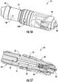
- FIG. 54depicts connector 10 according to the concepts disclosed having another housing footprint.
- FIGS. 56-61disclose cable assemblies 100 comprising connectors 10 having a first connector footprint where the connectors 10 may be convertible to connectors 10' having a second connector footprint using a conversion housing 80,82.
- FIGS. 70-78disclose a connectors where ferrule 30 is disposed within a ferrule holder 49 and inserted from a front end 23 of the connector 10.
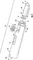
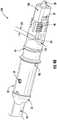
- FIG. 2is a perspective view and FIG. 3 is an exploded view of cable assembly 100 having connector 10 and a fiber optic cable 90 (hereinafter "cable").
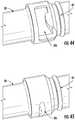
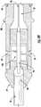
- FIGS. 15 and 16are longitudinal sectional views of the cable assembly 100 of FIG. 2 showing details of the construction.
- FIG. 2Adepicts cable assembly 100 having connector 10 with a housing 20 that is similar to the housing 20 for connector 10 of FIG. 2 , but the housing 20 of FIG. 2A has a different transition region TR. Specifically, the housing 20 of FIG. 2A has a transition region TR with a threaded portion TP and may be used with the connector constructions disclosed herein as appropriate.
- Connector 10comprises housing 20 and a ferrule 30.
- Housing 20comprises a rear end 21 and a front end 23 with a longitudinal passageway 22 extending from the rear end 21 to the front end 23.
- ferrule 30comprises a fiber bore 32 extending from a rear end 31 to a front end 33.
- Passageway 22allows one or more optical fibers of cable 90 to pass through the housing 20 for insertion into fiber bore 32 of ferrule 30 such as depicted in FIG. 7 .
- Cable 90comprises at least one optical fiber 92, one or more strength components 94 and a cable jacket 98.
- Connector 10 or components of connector 10 as depicted in FIGS. 2 , 2A , 3 and 5 -17allows ferrule 30 to be inserted into housing 20 from rear end 21 of housing 20. Specifically, ferrule 30 is inserted into an opening 21A at the rear end 21 of housing 20.
- Housing 20 depicted in FIG. 2Ais similar to the housing 20 FIG. 2 , except it has a different transition region (TR).
- the transition region (TR) of the housing 20 of FIG. 2Acomprises a threaded portion; otherwise the concepts of the connector are similar to the other disclosed herein.
- the thread portion (TR)allows the securing of an appropriate dust cap 70 and also allows for the conversion of the connector footprint such as to a hardened connector footprint such as shown in FIGS. 62-69 .
- the concepts of the rear inserted connector constructionsmay be used with any suitable housing disclosed herein.
- connector 10 of FIG. 3comprises housing 20, ferrule subassembly 60 and cable adapter 59.
- ferrule 30is a portion of ferrule subassembly 60.
- An opening 21A at the rear end 21 of housing 20is sized for receiving a portion of ferule sub-assembly 60.
- Ferrule sub-assembly 60is configured to cooperate with the housing 20 for inhibiting the rotation of the ferrule sub-assembly 60 with respect to housing 20 when assembled.
- ferrule sub-assembly 60may be configured to allow rotation of ferrule 30 for tuning as represented by arrows and angle ⁇ as desired before the ferrule sub-assembly 60 is fully-seated within housing 20 as discussed herein.
- Ferrule sub-assembly 60also comprises a ferrule carrier 40.
- Ferrule carrier 40may have different configurations as disclosed herein.
- Ferrule 30is tunable relative to housing 20 if desired and may have step-tuning in defined increments based on the ferrule geometry.
- other features or designs disclosed herein for the connectorsmay allow infinite tuning of the ferrule to any desired rotation position. Tuning ferrule 30 allows improved optical performance by turning the ferrule so that any eccentricity in the optical fiber, ferrule or connector is rotated to a known rotational position or quadrant in a uniform manner.
- connectors or other mating devicescan be tuned to similar relative rotational positions for improving optical performance such as reducing optical insertion loss of due to optical fiber core misalignment or the like as understood in the art.
- the design of connector 10 of FIG. 3may also advantageously allow multi-stage tuning if desired.
- Ferrule 30 or other components/assembliesmay be tunable in step increments such as by quadrants or be infinitely tuned as desired.
- ferrule sub-assembly 60may be may be configured to allow rotation of the subassembly with respect to cable adapter 59 (or other components) as desired for tuning ferrule 30 as represented by the arrows and angle ⁇ as depicted.
- multi-stage tuningmay result in infinite tuning, which means that any desired rotational position desired for any eccentricity of the fiber core within the ferrule 30 is possible.
- the step or degree of tuning at different component interfacesmay depend on the particular construction of the ferrule, ferrule carrier, cable adapter or housing with respect to the permitted of rotation and the possible increments of rotation for the components.
- a first-stage of tuningmay be step-tuning by quadrant and a second-stage of tuning may be infinite tuning to allow infinite rotation as desired. More specifically, the first-stage step-tuning may be used for gross tuning of the eccentricity of the fiber core such as to the desired quadrant of the and then the second-stage provides infinite tuning by allowing the fine tuning of the eccentricity of the fiber core within the quadrant for precise rotational positioning.
- infinite tuningmay accomplished by having one or more components rotate through an angle of ⁇ 180 degrees without step increments, thereby allowing any rotational position for ferrule 30.
- other tuning schemesare possible using the concepts disclosed herein.
- variations of ferrule carrier 40 or ferrule subassembly 60are possible and disclosed herein for use with any suitable housing 20.
- Connector 10 of FIG. 3allows ferrule 30 to be rotated or tuned within the ferrule subassembly 60 as depicted.
- Ferrule 30may be configured to rotate as a step rotation or infinite rotation depending on the particular design.
- ferrule 30could have a selectively tunable surface 36 that is round for providing infinite rotational positioning or selectively tunable surface of ferrule 30 could comprise a plurality of planar surfaces 36 for step tuning by only allowing certain rotation positions.
- infinite tuning of ferrule 30may be accomplished by tuning or rotating though an angle ⁇ of ⁇ 180 relative to the ferrule carrier 40 if desired. Being able to rotate one or more components in either direction allows for flexibility in tuning and inhibits excessive twisting of the optical fiber, which is generally undesirable.
- Connector 10 of FIG. 3also allows ferrule carrier 40 to be rotated for tuning the ferrule relative to housing 20 as depicted.
- ferrule carrier 40is tunable relative to the housing 20 by way of the rotational position of ferrule carrier 40 relative to cable adapter 59 or rotational position of the cable adapter 59 with respect to the housing.
- ferrule carrier 40may be tunable though an angle ⁇ of ⁇ 180 relative to the housing 40 or in step-increments such as using ferrule carrier rotational key 41K ( FIG. 5 ) or the like as desired.
- a ferrule carrier rear end 41may have one or more keys for cooperating with cable adapter 59 and only allowing certain positions for tuning, or the ferrule carrier rear end 41 may simply cooperate with the cable adapter 59 for providing infinite rotational positions for tuning. The details of tuning will be discussed in more detail below.
- connector 10 of FIG. 3it is possible for connector 10 of FIG. 3 to have to a third interface for tuning.
- the cable adapter 59may be tunable relative to the rear end 21 of housing 20.
- a flange portion (not numbered) of cable adapter 59may have one or more keys for cooperating with the rear end 21 of housing 20 and only allowing certain positions for tuning, or the flange portion of cable adapter 59 may simply cooperate with the rear end 21 of housing 20 for providing infinite rotational positions for tuning.
- connector 10 of FIG. 3provides several different tuning options for manufacturing depending on the desired requirements for the connector.
- FIGS. 4-4Edepict an explanatory housing 20 for connectors and will be described in further detail to explain concepts and geometry of housings 20 suitable for use with connector concepts disclosed herein.
- the housing of FIG. 4is a close-up perspective view of connector 10 having a different construction than the housing 20 depicted in FIGS. 2 and 3
- the housing 20 of FIG. 4is similar to housing 20 of the connector of FIGS. 2 and 3 .
- the footprint of housing 20 of FIG. 4may be used with connector constructions that insert the ferrule 30 from the rear end 21 of housing 20 or connector constructions that insert the ferrule 30 from the front end 23 of housing with appropriate modification(s) for the connector construction.
- the longitudinal passageway 22 of the housing 20may need to be modified for the different connector constructions as appropriate.
- Connectors 10 disclosed hereinmay use any suitable housing 20 with the desired footprint or construction.
- the disclosuredescribes several different housings that may be used with connector constructions as appropriate and other variations are also possible.
- FIG. 4depicts housing 20 and connectors 10 may use a variety of different variations of the housing shown in FIG. 4 or other housings such as the housing 20 shown in FIG. 54 which has the locking feature on a separate component.
- housing 20may comprise one or more features for alignment during mating and may also comprise other features for securing or locking the connector in a suitable complimentary port or device.
- Housing 20has a relatively compact form-factor such as having a length L of about 40 millimeters (mm) or less and a cross-section dimension of about 15 mm or less such as 12 mm or less, but other suitable dimensions are possible for the housing.
- FIGS. 4A-4Dare respective cross-sectional views of the housing of FIG. 4 taken along respective planes defined by line 4A-4A, line 4B-4B, line 4C-4C and line 4D-4D. Lines 4B-4B and 4C-4C are taken at the same cross-section.
- FIG. 4Eis a side view of housing 20 that is similar to housing 20 shown in FIG. 4 , but further includes threads 28 like housing 20 depicted in FIGS. 3 and 4 . Threads 28 are disposed on the front portion FR of housing 20 and are discontinuous.
- Housing 20comprises the rear end 21 and the front end 23 with a longitudinal passageway 22 extending from the rear end 21 to the front end as shown in FIG. 4E .
- Housing 20 of FIGS. 4A-4Ecomprises a part of the rear portion RP having a round cross-section RCS and a part of the front portion having a non-round cross-section NRCS.
- Transition region TRis disposed between the rear portion RP and the front portion FP of housing 20.
- Transition region TRcomprises a first transition portion TP1 disposed on a first side of the housing and a second transition portion TP2 disposed on a second side of the housing.
- first transition portion TP1 and the second transition portion TP2are spaced apart by an offset distance OD in the longitudinal direction of the housing 20 as best shown in FIG. 4E .
- the offset distance OD for the transition portion TPis useful since it allows connector only to fully-seat into complimentary devices or ports having the matching geometry.
- other housings 20 for connectors disclosed hereinmay omit the offset distance if desired.
- Housings 20may also have suitable features or structures for sealing connectors 10.
- the sealing planeshould be located at a suitable location along the housing 20 for providing suitable environmental protection as necessary for the desired environment.
- housing 20may include one or more grooves 20G for receiving an appropriately sized O-ring 65.
- Housings 20may include other feature or structures for aiding in sealing.
- the housing 20may have a suitable surface for receiving a portion of a heat shrink 99 or the like for sealing between a portion of the cable 90 and the connector 10. Any suitable heat shrink 99 may be used such as a gluelined heat shrink.
- other structures or featuresare possible for aiding in providing a robustly sealed cable assembly 100.
- the transition region TRis disposed between the rear end 21 and the front end 23 where the housing 20 makes a transformational shift in the primitive cross-sectional shapes from a part of a rear portion RP to a part of the front portion FP.
- a primitive cross-sectionmeans the outer perimeter of the cross-section without regard for the internal features of the cross-section.
- portions of the cross-sectionsmay include other features that modify the shape of the primitive cross-sections as desired such as a keying feature, retention feature or a locking feature, while still practicing the concepts of the transition region TR or front/rear portions as disclosed herein.
- a front portion FPmay have rounded corners or chamfered corners while still being a rectangular cross-section.
- the front portion FP of housing 20has a rectangular cross-section that provides a first orientation feature for the connectors for alignment during mating and inhibit insertion into a non-compliant device or port.
- the non-round cross-section NRCShas the rectangular cross-section with a width W1 and a height H1 as shown in FIG. 4B .
- the rectangular cross-sectionprovides the first orientation feature since the rectangular portion may only be inserted into a complimentary device or port in certain orientations due to its rectangular shape, thereby inhibiting incorrect insertion or insertion into non-compliant devices or ports.
- housing 20 of FIGS. 4A-4Ehas the first transition portion TP1 that comprises a first riser dimension FRD from the non-round cross-section NRCS to the round cross-section RCS, and the second transition portion TP2 comprises a second riser dimension SRD from the non-round cross-section NRCS to the round cross-section RCS, where the first riser dimension FRD is different that the second riser dimension SRD.
- the riser dimensionsare measured perpendicular from the mid-point of the cord defined by the surface of non-round cross-section NCRS as shown in FIG. 4C to the outer surface of the round cross-section RCS.
- the geometry of housing 20 of FIGS. 4A-4Ealso comprises the non-round cross-section NRCS comprising a rectangular cross-section having rounded corners RC, and the rounded corners RC are sized so they have a similar outer dimension OD as a dimension D for the round cross-section RCS.
- the rounded corners (RC)may provide stability and snug fit for the mated connector 10 within a port or device when side-pull forces are experienced to inhibit undue optical attenuation by having the round corners transition between the front portion FP to the rear portion RP.
- the front portion FP of housing 20 depictedhas more than one primitive cross-sectional shape over its length.
- the front portion FP of housing 20 of FIGS. 4-4Ealso comprises another cross-section portion ACSP.
- the another cross-sectional portionmay comprise a SC footprint.
- the SC footprintcan, in part, be similar to the inner housing of a conventional SC connector. This particular housing footprint is useful for allowing the connectors disclosed to be backwards compatible into existing devices or ports using well-established connector footprints as desired.
- the connectorsmay be configured for LC connector or other known connector footprints as desired.
- the front portion FP of housing 20may comprise another cross-section portion ACSP with a primitive cross-section that is different than the non-round cross-section NRCS depicted in FIG. 4D .
- the non-round cross-section NRCSchanges to another cross-section portion ACSP as shown.
- the another cross-section portioncomprises a rectangular cross-section with a width W2 that is less than W1 and a height H2 is similar to height H1.
- height H2may be equal to height H1.
- the another cross-section portion ACSPmay have a primitive cross-section that is similar to a cross-section near a front end of a SC connector.
- rear portion RPmay have more than one primitive cross-section shape over its length as desired.
- rear portion RPmay include one or more retention features or locking features that alter or modify the cross-section.
- housing 20may also include locking feature 20L so that the connector may secured in an adapter, port or other suitable device.
- locking feature 20Lmay comprise features integrated into the housing such as one or more of a groove, a shoulder such as shown in FIG. 4E and FIG. 45 , a scallop such as shown in the housing 20 of FIG. 3 , a reverse bayonet such as depicted in FIG. 44 , or a ramp with a ledge such as shown in FIG. 71 .
- the locking features 20Ladvantageously are integrated into the housing 20 and do not require extra components and may be used with any of the disclosed concepts.
- the locking features 20Lmay be subtractive portions from the primitive geometry of the rear portion RP such as a notch in the round rear portion RP. Consequently, having the locking features integrated into the housing 20 (e.g., monolithically formed as part of the housing) may allow denser arrays of connectors in complimentary devices.
- these locking features integrated into the housing 20are rearward of the sealing location of connectors 10.
- the integrated locking features of housing 20are disposed rearward of at least one groove 20G that seats O-ring 65. Locking feature 20L may cooperate with features of a complimentary mating device for securing the mating of the connector 10 with the complimentary mating device.
- Housing 20may also have features that aid in the proper alignment or orientation of the connector with the complimentary device such as markings, keys, keyways, etc. without changing the primitive form-factors of the housings that are disclosed and claimed herein. Additionally, housing may have other features for mating with a complimentary device or threads for securing a dust cap.
- FIG. 2is a perspective view of connector 10 with a housing 20 similar to the housing 20 depicted in FIG. 4 , but it further includes threads 28 and keying feature 20K.
- FIGS. 25 and 26depict a fiber optic connector similar to FIG. 20 having an alternative housing 20A that may be used with any suitable fiber optic connector disclosed herein. Housing 20 further comprises a keying feature 20K.
- Keying feature 20Khas a predetermined location with respect to an orientation of housing 20 for aligning the form-factor of the housing with a respective mating device.
- the housing 20 or keying feature 20Lprovides a proper orientation for connection in one orientation, which may be desired for connectors having angled ferrules.
- keying feature 20Kensures correct rotational orientation of the connector 10 during insertion and mating with another device.
- the housing 20is monolithically formed; however, the housing may alternatively be formed from one or more components as desired. Housing 20 having a plurality of components could be assembled by snap-fitting, adhesive, welding or the like. Illustratively, FIGS. 39 and 40 depict a housing 20 having a plurality of components.
- FIG. 5is an exploded view of ferrule subassembly 60 shown in connector 10 of FIG. 3 .
- Ferrule subassembly 60may have several different constructions as depicted herein and still practice the concepts disclosed. For instance, ferrule subassemblies 60 may use different ferrule carrier 40 constructions such as disclosed or desired while still practicing the concepts disclosed.
- Ferrule 30is a portion of ferrule subassembly 60.
- An opening 21A at the rear end 21 of the housing 20is sized for receiving a portion of the ferrule subassembly 60.
- the ferrule subassembly 60is configured to cooperate with the housing 20 for inhibiting the rotation of the ferrule subassembly 60 with respect to the housing 20.
- the ferrule subassemblymay have a friction fit or interlocking structure that cooperates with the passageway 22 of the housing 20 that inhibits rotation of the ferrule subassembly 60 with respect to housing 20.
- the ferrule subassembly 60may be free to rotate for tuning or the like until the ferrule subassembly 60 is fixed in position relative to housing 20 such as with an adhesive or the like.
- ferrule subassembly 60comprises a ferrule carrier and a resilient member 50.
- the ferrule subassembly 60may omit the resilient member 50 and not bias the ferrule 30 forward.
- ferrule carrier 40may further comprise a resilient member pocket 46 as shown.
- the resilient member pocket 46may be configured for receiving the resilient member 50 in a direction transverse to a longitudinal direction of the ferrule carrier 40 (e.g., transverse to the optical fiber passageway) as represented by the arrow.
- ferrule carrier 40comprises a ferrule carrier rear end 41, a ferrule carrier front end 43 and a ferrule carrier passageway 42 extending from the ferrule carrier rear end 41 to the ferrule carrier front end 43, where the ferrule carrier passageway 42 comprises a fiber buckling zone 47.
- the fiber buckling zoneallows the optical fiber 92 to have room to move rearward during mating without causing undue optical attenuation. In other words, during mating the ferrule 30 may be pushed rearward slightly cause the optical fiber 92 of the cable 90 to deflect and in order to inhibit optical attenuation the fiber buckling zone 47 provided for allowing fiber movement.
- Ferrule carrier 40may have several different designs.
- the ferrule carriermay comprise a ferrule carrier front end 43 with the ferrule carrier front end 43 comprising at least one cantilevered portion such as shown in FIG. 10 .
- the at least one cantilevered portionextends from a medial portion of the ferrule carrier and allows the assembly of the ferrule 30 into the ferrule carrier 40.
- the at least one of the first cantilevered portion 43Amay also be configured to cooperate with the housing 20 for inhibiting the rotation of the ferrule 39 with respect to the housing 20 when the ferrule subassembly 60 is fully-seated in the housing 20, and allow rotation of the ferrule 30 for tuning when the ferrule subassembly 60 is not seated in the housing 20.
- the front portion of the longitudinal passageway 22 of housing 20may be sized for snuggly fitting to shoulders 43S disposed on the ferrule carrier front end 43 so that one or more of the cantilevered portions either squeeze the ferrule 30 and inhibit rotation or inhibit the deflection of the at least one cantileved portion so that the ferrule 30 is inhibited from rotating beyond its desired location.
- the ferrule carrier 40still allows the ferrule 30 to "float" to the desired degree so it can translate such as in the rearward direction (i.e., z-direction) or X-Y directions for allowing the ferrule to move slightly to the desired location for precise alignment during mating.
- the ferrule 30is biased and may "float" on the resilient member.
- ferrule carrierdescribed herein should not be confused with a ferrule holder that fixes a conventional ferrule directly to the ferrule holder so there is no appreciable movement between the ferrule and the ferrule holder.
- Conventional connectorsallow the entire assembly of the ferrule holder/ferrule to be biased by a spring.
- FIG. 17 and FIG. 21allow the ferrule to float without using a ferrule holder.
- the use of the ferrule holder/ferrule assemblyis another component interface where stack-up of tolerances may exist and impact geometry. Consequently, connectors disclosed herein may eliminate the conventional ferrule holder along with the expense and manufacturing time required by using a conventional ferrule holder.
- FIG. 5depicts the ferrule carrier front end 43 comprising a first cantilevered portion 43A and a second cantilevered portion 43B.
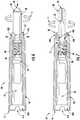
- FIGS. 6 and 7are longitudinal sectional views of ferrule subassembly 60 of FIG. 3 showing details of the design and assembly.
- FIGS. 8 and 9respectively are a perspective view and close-up perspective view of ferrule carrier 40 of FIGS. 5-7 depicting details of the ferrule carrier.
- At least one of the first cantilevered portion 43A or the second cantilevered portion 43Bmay be configured to cooperate with the housing 20 for inhibiting the rotation of the ferrule 30 with respect to the housing 20 when the ferrule subassembly 60 is fully-seated in the housing 20, and allow rotation of the ferrule 30 for tuning when the ferrule subassembly is not seated in the housing 20.
- the housing 5may be sized to cooperate with the housing 20 by fitting into a passageway 22 that inhibits the cantilevered portions 43A,43B from deflecting outwards, thereby inhibiting the rotation of the ferrule 30 with respect to the ferrule carrier 40 when the ferrule carrier front end 43 is fully-seated in the housing 20 since some of the selectively tunable surfaces 36 (in this case the planar surfaces 36S) of ferrule 30 cooperate with ferrule retention structure 43C of the ferrule carrier 40.
- the selectively tunable surfaces 36in this case the planar surfaces 36S
- Ferrule subassembly 60is assembled by placing the resilient member 50 into the resilient member pocket 46 by inserting the spring in the transverse direction to the ferrule carrier passageway as best shown in FIG. 5 .
- Ferrule carrier 40 of FIG. 5allows ferrule 30 to be inserted from the ferrule carrier front end 43 as represented by the arrow.
- the first cantilevered portion 43A and the second cantilevered portion 43Bdeflect outward as represented by the arrows shown in FIG. 6 .
- the ferrule 30is seated in the ferrule carrier front end 43 the first cantilevered portion 43A and the second cantilevered portion 43B spring back toward their original positions to capture the ferrule 30.
- one of the first cantilevered portions 43A or the second cantilevered portions 43Bcomprise a ferrule retention structure 43C. Consequently, when the first and second cantilevered portions 43A,43B are inhibited from deflecting, then ferrule 30 is inhibited from rotating such as when the ferrule subassembly 60 is fully-seated within housing 20. However, when the first and second cantilevered portions 43A, 43B are allow to deflect outwards such as shown in FIG. 6 , then the ferrule 30 may be rotated thru any desired angle ⁇ for tuning.
- ferrule carrier 40may have other features that allow tuning if desired.
- ferrule carrier rear end 41may have a ferrule carrier groove 41G or shoulder for cooperating with the cable adapter 59, thereby allowing rotation between the two components in either step increments or infinite increments as desired and discussed herein.
- ferrule carrier 40may comprise one or more ferrule carrier rotational keys 41K to allow rotational step increments or the ferrule carrier 40 may omit ferrule carrier rotational keys 41K and allow infinite rotational positions relative to the cable adapter 59, which may be keyed to the rear end 21 of housing 20.
- Ferrule carrier 40may be attached to cable adapter in any suitable manner such as adhesive, welding, mechanical fitment, etc.
- the ferrule carrier 40 and cable adapter 59may be integrated into a monolithic component. However, using separate cable adapter 59 allows the connectors 10 to be adapted to different cables such as round, flat, different sizes by merely selecting the appropriate sized cable adapter 59 for the desired cable type. Additionally, cable adapter may include one or more flexures 59F at the rear portion for providing cable bending strain-relief if desired instead of using a conventional boot. The flexures as depicted are suitable for flat cables that have a preferential bend-characteristic.
- the connectors disclosed hereinmay allow the ferrule 30 to have a small amount of "float" within ferrule carrier or housing without using a ferrule holder like conventional fiber optic connectors.
- Conventional connectorsmount the ferrule within a ferrule holder in a fixed position and then typically the ferrule holder is biased by a spring.
- some of the connector designs disclosed by the present applicationhave the resilient member 50 directly bias the ferrule, which eliminates parts and also allows more flexibility for ferrule selection or tuning.
- the ferrulemay be tuned relative to the ferrule carrier or the housing depending on the connector design.
- the high precision geometry ferrule holderis eliminated along with the tolerance stack-up using a conventional connector with a ferrule holder.
- the housings concepts disclosed hereinmay be used with connectors having ferrule holders such as disclosed in FIGS. 70-78 .
- Ferrule retention structure 43Cis configured to cooperate with geometry on ferrule 30. Specifically, ferrule 30 depicted in FIG. 5 has at least one selectively tunable surface 36 that cooperates with the ferrule retention structure 43C. Ferrule retention structure 43C is sized for snugly-fitting to one or more selectively tunable surfaces 36 of ferrule 30 as shown in FIG. 7 . However, when the ferrule carrier 40 is not seated in housing 20, the ferrule 30 may be rotated within ferrule carrier 40 about an angle ⁇ for optically tuning the assembly. Ferrule 30 may have a round selectively tunable surface 36 for infinite tuning, but that requires a tight fit between the ferrule carrier front end 43 and the appropriate portion of the passageway 22 of the housing 20.
- FIGS. 8 and 9depict detailed views of the ferrule carrier 40 of FIG. 5 .
- the first and second cantilevered portions 43A,43B of ferrule carrier 40may have stepped down portions forward of shoulder 43S, thereby allowing robust seating and inhibiting of deflection of the cantilevered arms 43A,43B.
- Ferrule 30may have any suitable number of plurality of planar surfaces 36S as desired.
- four planar surface 36Sallows quadrant tuning and further planar surfaces allows finer tuning in a first-stage.
- ferrules 30may have any number of planar surfaces as desired such as six or eight planar surfaces to increase the number of steps for tuning the ferrule.
- quadrant tuningis sufficient and if coupled with an infinite sccond-stagc tuning interface, then the connector advantageously may be tuned to any desirable rotational position in a quick and easy manner during manufacturing.
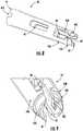
- FIG. 10is a perspective view of an alternative ferrule carrier 40' that may be used in the ferrule subassembly 60 and FIGS. 11 and 12 respectively are a partially exploded view and an assembled view of the alternative ferrule carrier 40' in ferrule subassembly 60.
- This ferrule carrier 40'is similar to ferrule carrier 40, but only has first cantilevered arm, and requires loading of the ferrule 30 from the transverse direction like the resilient member 50. Ferrule 30 may still be rotated with respect to ferrule carrier 40', but it may require a slightly larger rotational force to deflect the U-shaped portion or a slightly upward translation of the ferrule 30 to help reduce the rotational force required for the rotation.
- FIGS. 13 and 14respectively are a partial sectional view and a cross-sectional view of the alternative ferrule carrier 40' of FIGS. 10-12 depicted assembled into ferrule subassembly 60 and disposed in housing 20 of fiber optic connector.
- the passageway 22 of housing 20may include different geometry for seating the ferrule subassembly 60 within the housing and inhibiting the rotation of ferrule 30 relative to the housing 20 using the alternative ferrule carrier 40'.
- housing 20comprises a passageway 22 with an internal key 20KI that cooperates with the U-shaped portion of the alternative ferrule carrier 40'. Consequently, the alternative ferrule carrier is inhibited from further rotation with respect to the housing 20.
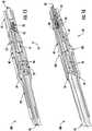
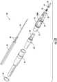
- FIG. 17is an exploded view of another cable assembly 100 that is similar to the cable assembly 100 of FIG. 2 with a fiber optic connector having a different ferrule subassembly 60 and FIG. 18 is a partially exploded view of the cable assembly 100 of FIG. 17 with the fiber optic cable attached to the ferrule subassembly 60.
- This cable assembly 100comprises a connector 10 that has a ferrule carrier 40 that is monolithically formed with the cable adapter as depicted. Otherwise, the cable assembly 100 is similar to the cable assembly 100 of FIG. 2 .
- FIGS. 19-43 and FIGS. 46-53disclose connectors where ferrule 30 is inserted from a front end 23 of the connector 10. These connectors designs are depicted without a ferrule holder as generally discussed herein, but may be used with a ferrule holder if desired. These connector designs are different from the earlier connector designs since they do not use a ferrule carrier; however, these designs can still be optically tuned if desired. Specifically, these connector designs comprise a ferrule 30 that "floats" relative to the housing 20 and uses a different structure for securing the ferrule while allowing the ferrule float. Any suitable housings 20 as described herein may be used for these connectors so long as they are suitably modified for securing the ferrule 30 as disclosed in more detail below.
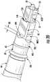
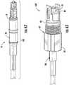
- FIGS. 19 and 20are perspective views of cable assembly 100 having a different fiber optic connector 10 with housing 20 that is similar to the housing shown with the fiber optic connector of FIG. 2 , but having ferrule 30 that loads from the front end 23 of housing 20 and secured a transverse ferrule retention member 140.
- FIG. 21is an exploded view of another cable assembly 100, that is similar to that of FIG. 19 with the connector having a housing having threads on the housing that are discontinuous.
- FIG. 22is an perspective assembled view of the cable assembly 100 of FIG. 21 and FIG. 23 is a perspective view of the cable assembly 100 of FIG. 22 with a dust cap 70 installed.
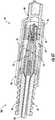
- FIG. 24is a longitudinal sectional view of the cable assembly 100 of FIG. 22 in a vertical direction and
- FIG. 29is a longitudinal sectional view of a front portion of the fiber optic connector 100 in a horizontal direction.
- connector 10comprises housing 20, ferrule 30 and transverse ferrule retention member 140.
- Housing 20is similar to the other housings disclosed herein, but further comprises an opening 129 in an outer surface that is transverse to the longitudinal passageway 22 of housing 20.
- the opening 129is sized for receiving the transverse ferrule retention member 140 and securing the ferrule 30 in a manner that allows suitable movement so it may float as appropriate as depicted in FIG. 24 .
- Connector 10may also comprise a band 69 for securing a cable 90 to the connector if desired.
- FIG. 25is a detailed exploded view of the front end of the cable assembly 100 of FIG. 22 and FIG. 26 is a cross-sectional view taken at the opening 129 of the housing 20 of FIG. 19 showing transverse ferrule retention member 140 securing the ferrule 30.
- ferrule 30is loaded into the passageway 22 of housing 20 from the front end 23 and secured by the cooperation of the ferrule 30 with the transverse ferrule retention member 140 that is inserted into opening 129 for cooperating with at least one surface of the ferrule 30.
- ferrule 30is inserted into the passageway 22 until the cooperating surface such as a ferrule retention feature aligns with the opening 129 so that the transverse ferrule retention member 140 may engage the surface and securing the ferrule. Additionally, the at least one surface of the ferrule 30 that serves as the ferrule retention feature cooperates with the transverse ferrule retention member 140 is sized relative to the transverse ferrule retention member so that the ferrule 30 may float.
- the ferrule retention featuremay also be the same feature as the at least one selectively tunable surface 36.
- Ferrulehas at least one selectively tunable surface 36 so that ferrule 30 may have at least two rotational orientations with respect to the housing 20 (and which acts as the ferrule retention feature).
- ferrules 30may have any suitable numbers of selectively tunable surfaces 36 so the ferrule 30 may have the desired number of rotational positions for tuning the ferrule.
- ferrulemay have four, six, eight or any suitable number of selectively tunable surfaces 36 as desired.
- the longitudinal passageway 22 of housing 20 extending from the rear end 21 to the front end 23also comprises a tuning pocket 24 in cooperation with the longitudinal passageway 22. The tuning pocket 24 allow the rotation or manipulation of the ferrule 30 within the housing as needed.
- the transverse ferrule retention member 140is secured to the housing 20 using a pair of catches 140C disposed on the arms of the transverse ferrule retention member 140.
- Catches 140Cmay snap-fit to portions of the housing 20 disposed in opening 129 such ledges.
- FIGS. 27 and 28respectively depict a detailed view of an alternative transverse ferrule retention member 140 having catches 140C and cross-sectional view showing the alternative transverse ferrule retention member 140 for securing ferrule 130.
- the catches 140Care disposed on a medial portion of the arms of this alternative transverse ferrule retention member 140.
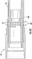
- FIG. 29is a sectional view of a portion of the housing 20 having a width of opening 129 being larger than the width of the transverse ferrule retention member 140 so that the ferrule 30 may float.
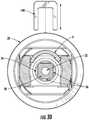
- FIG. 30is a sectional view depicting tuning pocket 24 of housing 20 that allows rotational tuning of the ferrule 30 during manufacture for improving optical performance. Specifically, when transverse ferrule retention member 140 is disengaged, then the ferrule 30 may be rotated relative to the ferrule.
- tuning pocket 24allows ferrule 30 to be rotated by a suitable angle ⁇ for optical tuning to a preferred rotational position as represented by the arrow.
- ferrule 30may be rotated by an angle ⁇ of ⁇ 180 degrees, but other suitable angles are possible.
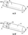
- FIGS. 31 and 32depict explanatory ferrules 30 having at least one selectively tunable surface 36.
- FIG. 31shows a ferrule that may be tuned to quadrants with four selectively tunable surfaces 36.
- the selectively tunable surfaces 36are configured as planar surfaces as shown. More specifically, the selectively tunable surfaces 36 are formed by a plurality of planar surfaces that are recessed on the ferrule 30. Finer tuning is possible with the concepts disclosed by having more selectively tunable surfaces such as six, eight, ten or twelve, thereby providing more rotational positions for securing the ferrule 30.
- FIG. 31shows a ferrule that may be tuned to quadrants with four selectively tunable surfaces 36.
- the selectively tunable surfaces 36are configured as planar surfaces as shown. More specifically, the selectively tunable surfaces 36 are formed by a plurality of planar surfaces that are recessed on the ferrule 30. Finer tuning is possible with the concepts disclosed by having more selectively tunable surfaces such
- the ferrule 30 in FIG. 32may be secured by transverse retention member 140 and when rotational tuning is required, then the ferrule 30 may be displaced rearward until free rotation portion 36A is aligned with the transverse retention member 140 allowing rotation of the ferrule in either direction and when the desired rotational position is reached the ferrule 30 is allowed to translate to the forward position where the selectively tunable portions 36 engage and cooperate with the transverse ferrule retention member 140 to inhibit rotation of the ferrule 30. Consequently, the transverse ferrule retention member 140 does not need to be removed from housing 20 for tuning.
- FIGS. 33-36are various views of depicting the housing 20 of the connector 10 of FIG. 23 comprising opening 129 and tuning pocket 24.
- housing 20is similar to the other housings and may be modified for the desired housing configuration as desired.
- the housing 20depicts threads 28 that are discontinuous for attaching dust cap 70 such as shown in FIG. 23
- variationsare possible that eliminate the threads 28 and use a push-on dust cap.
- other variations to the housing 20are possible such as changing the mating geometry and using the concepts disclosed with the mating geometry of the housing 20 depicted in FIG. 54 .
- housings 20may have different retention features or different locking features 20L.
- FIG. 3comprises a locking feature 20L disposed between rear end 21 and a front end 23 configured as a scallop and the locking feature 20L of the housing of FIG. 4 is configured by a shoulder.
- the shouldercomprises an enlarged annular portion 126 with a flat surface on the rear side.
- FIG. 37is a perspective view of another cable assembly 100 with still another alternative connector 10 that is similar to connector 10 of FIG. 19 , but further comprises multi-piece housing 20 comprising a nosepiece 160.
- FIG. 38is a perspective view of the cable assembly 100 with dust cap 70 and
- FIG. 39is an exploded view of the cable assembly 100.
- the connector 10comprises a housing 20 having nosepiece that fits about a front end 23.
- using the separate nosepiece 160provides more access to the passageway 22 of the housing and allows more room and vision for assembly.
- the opening 129is disposed in a location that is covered by nosepiece 160 so that once the connector is tuned and the nosepiece 160 is secured the transverse ferrule retention member is not visible or accessible.
- Housing 20 of FIG. 39also has a different locking feature 20L compared with the housing depicted in FIG. 33-36 and an aperture 29.
- Locking feature 20Lis configured as a groove for receiving a clip or other suitable locking feature from a complimentary device for retaining the connector in a mated state when secured.
- This connectoralso uses cable adapter 59 so that the connector may accommodate different cable types by using the appropriately sized cable adapter for the given cable 90.
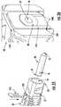
- FIG. 40is a front end sectional view of the connector 10 of FIG. 37 showing the nosepiece 160 attached to the front end of housing 20 and
- FIG. 41is a front end view of the housing showing an attachment interface (not numbered) such as a weld interface disposed on a front portion of the housing 20.
- an attachment interfacesuch as a weld interface disposed on a front portion of the housing 20.
- Nosepiece 160may be attached in any suitable manner such as adhesive, friction-fit, snap-fit, welding or the like as desired.
- the nosepiece 160may be formed from a translucent material. Using a translucent material for nosepiece 160 allows the use of a UV curable epoxy for securing the nosepiece 160.
- FIGS. 42 and 43are perspective and side views of a connector 10 similar to FIG. 37 having an alternative housing 20.
- Housing 20 in this embodimentdoes not have an offset distance among transition portions TP1-TP4. In other words, all of the transition portions TP1-TP4 are aligned.
- this housing 20comprises keying feature 20K for orienting the connector for mating.
- Keying feature 20Kis a key, alternatively other suitable structure such as a keyway or the like may be used.
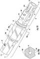
- housings disclosed hereinare also possible such as having other shapes for the rear portion RP such as a polygon cross-section PCS, instead of the round cross-section RCS.
- Polygon cross-sectionsmay have any suitable number of side such as four, five, six, seven or eight, but other suitable number of sides are also possible.
- the housing 20 of the connectorsmay be configured to work with other devices so that a retention feature or locking feature of the connector is intended to cooperate with different devices for maintaining the optical connection at the mating interface.
- FIGS. 44 and 45are perspective views of portions of alternative housings 20 depicting other locking feature designs. The housings 20 depicted in FIGS. 44 and 45 may be used with any suitable connectors disclosed herein.
- Keying feature 20Khas a predetermined location with respect to an orientation of housing 20 for aligning the connector form-factor with a respective mating device. Specifically, the housing 20 provides a proper orientation for connection in one orientation, which may be desired for angled ferrules. In FIGS. 44 and 45 , keying feature 20K is disposed on a center line of fiber optic connector 10 and ensures correct rotational orientation during insertion and mating with another device.
- FIG. 46is a perspective view of still another cable assembly 100 using a connector similar to the connector of FIG. 37 , but having a different cable adapter 59.
- the connectoralso has a different type of locking feature 20L than the housing 20 of the connector of FIG. 37 .
- the cable adapter 59that fits into a rear opening 21A of the housing 20.
- using connectors with a separate cable adapter 59allows the connector to be used with different types cables by merely changing out and selecting the cable adapter that is suitable for the desired cable 90.
- FIG. 47 and 48respectively are a perspective view and a cross-sectional view the cable adapter 59 of FIG. 46 .
- FIG. 49is a vertical sectional view and
- FIG. 50is a horizontal sectional view of the rear portion of cable assembly 100 showing the cable 90 disposed within the cable adapter 59.
- FIGS. 47A and 48Aare a perspective view and a cross-sectional view of another cable adapter 59, that is similar to the cable adapter of FIG. 47 .
- cable adapters 59may comprise an aperture 59A, a recessed surface 59R, a shoulder 59S, a passageway 59P, and a cable saddle 59C or a cable adapter key 59K as desired for any particular cable adapter 59.
- cable adapter 59comprises passageway 59P from a cable adapter front end 59F to a cable adapter rear end 59R. Passageway 59P allows the optical fiber 92 of cable 90 to pass therethrough.
- Housings 20may include one or more aperture 29 for injecting epoxy or adhesive or the adhesive or epoxy may be placed on the cable adapter before insertion into the housing.
- housingmay include two apertures 29 such as show in FIG. 49 so that air may escape as adhesive or epoxy is injected.
- the one or more apertures 29may be aligned with the apertures 59A of the cable adapter so that the adhesive or epoxy also secures the strength members 94 of cable 90 to the cable adapter 59 that is secured to the housing 20, thereby forming a robust cable/connector attachment and also providing sealing at the rear end.
- Cable saddle 59Cis sized and shaped for the particular cable 90 that is intended to be secured using the cable adapter along with the appropriate components as appropriate such as depicted in FIG. 50 .
- the rear portion of the cable adapter 59may have a cable bend relief area such as a reverse funnel at entrance to the passageway, flexures or other suitable structure for inhibiting sharp bending of the cable near the rear of the cable adapter 59.
- cable adapters 59may or may not include keys 59K as desired for cooperating with features of the housing.
- the rear portion 59R of the cable adapter 59 of FIG. 47Acomprises one or more ribs 59RB suitable for receiving a boot or overmold on the rear portion 59R.
- the ribs 59RBaid in the retention of the boot or overmold.
- FIG. 51is perspective view of a cable assembly 100 according to the invention, according to the concepts disclosed and FIG. 52 is an exploded view of the cable assembly 100.
- Housing 20 of this embodimentis similar to the housing disclosed herein, but further comprises a keying portion 20KP that extends into the transition region TR as shown, but embodiments without the keying portion 20KP are possible.
- the transition region TR of this housingis asymmetric. Specifically, the asymmetric transition region is a threaded portion TP, but other asymmetric geometries are possible as disclosed herein.
- the keying portion 20KPis configured as a female key or a subtractive portion on housing 20 such as a female keyway or a slice on the side of the connector leaving a D-shape.
- the keying portion 20KPextends into the transition region as shown.
- the keying portion 20KPcooperates with a suitable keying portion in a connection port of a device such as an additive or male portion for inhibiting non-compliant connectors from being inserted into the connection port.
- a suitable keying portionin a connection port of a device such as an additive or male portion for inhibiting non-compliant connectors from being inserted into the connection port.
- the keying portion 20KPis disposed about 180 degrees from the at least one locking feature 20L, other arrangements are possible where the keying portion 20KP is disposed less than 180 degrees from the at least one locking feature 20L.
- keying portion 20KPmay be arranged as a subtractive portion that removes a side or slice of the housing 20 for creating a D-shaped cross-section over the length of the keying portion 20KP; instead of the female keyway shown.
- connector 10 of FIG. 52is similar to that of FIGS. 70-78 where ferrule 30 disposed within a ferrule holder 49 and inserted from a front end 23 of the connector 10 and is discussed in more detail in relation to those FIGS.
- This embodimentalso comprises a boot or overmold 259 disposed on the rear portion 59R of cable adapter 59 as best shown in FIG. 53 .
- a sealing elementsuch as heat shrink 99 is disposed over the boot or overmold 259 as best shown in FIG. 54 .
- the sealing elementmay also be disposed over a portion of the housing 20 as shown. Placing the sealing element over boot or overmold and a portion of the housing 20 allows for sealing of the cable jacket to the rear of the connector. This may also improve the bending strain-relief for the cable assembly.
- FIG. 51Ais a rear perspective view of another cable assembly having cable adapter 59 with flexures 59F for bend-strain relief.
- FIGS. 52A and 53Aare a side and sectional views of the cable assembly of FIG. 51A showing heat-shrink 99 before and after being installed.
- the cable adapter 59uses flexures 59F they are generally aligned with the flat portions of cable 90 for cable bend relief.
- the cable adapter 59may or may be able to have more than one rotational position with respect to the housing 20 depending on how the ends of the components cooperate or not.
- housing 20may have a stepped down portion at the rear end 21 for receiving a portion of heat shrink 99 and may cover the flexures 59F while also providing further cable bending strain-relief.
- FIG. 54Ais a front perspective view of another housing 20 that may be used with the fiber optic connector concepts disclosed herein.
- the securing featureis formed on a separate and distinct component from the housing 20.
- securing featureis disposed on a coupling nut 120 having threads and that rotates about an outer shaft of housing 20 for securing the connector to a complimentary device.
- the housing 20may not have offset distance between transition portions of the housing 20 such as depicted.
- Connectors disclosed hereinmay be portions of other cable assemblies as desired.
- FIG. 55depicts a distribution cable 100' having one or more connectors 10 on tether cables 90' that extend from a mid-span access 93 of a distribution cable.
- other suitable assembliesmay use the connectors according to the concepts disclosed herein.
- FIG. 56is a perspective view of an explanatory connector 10' that further comprises a conversion housing 80 attached about the housing 20 for changing the connector 10' from a first connector footprint to a second connector footprint
- FIG. 57is a sectional view of the connector 10'.
- the connector 10'may have a first connector footprint such as shown in FIG. 19 and be changed to a second connector footprint such as a SC connector by adding conversion housing 80.
- Conversion housing 80cooperates with housing 20 for changing from the first connector footprint to the second connector footprint.
- the changing of the first connector footprint to the second connector footprintcomprises the use of a single component.
- FIG. 58is a partially exploded view of another connector 100' that may be changed from a cable assembly 100 having first connector footprint 10 to a second connector footprint 10' as shown assembled in FIG. 59 .
- this embodiment of the second connector footprint 10'comprises a hardened connector footprint.
- Hardened connector footprintmeans that the connector is suitable for outdoor environments without be protected within a closure. Any suitable connector 10 disclosed herein may be used for such a conversion from the first footprint to the second footprint.
- FIG. 58depicts cable assembly 100 with connector 10 with the plurality of components for the conversion to the second footprint exploded for depicting the assembly of the components.
- FIG. 58depicts cable assembly 100 with connector 10 with the plurality of components for the conversion to the second footprint exploded for depicting the assembly of the components.
- the plurality of componentsare suitable for converting connector 10 to a hardened OptiTap® compatible connector; however, the plurality of components may be configured for converting connector 10 into other hardened connectors as desired.
- the plurality of components for the conversion to the hardened connectorcomprise an inner boot 83, an outer boot 87, a conversion housing 82 configured as a shroud, a retaining member 84 configured as a retaining nut and a coupling nut 85.
- the inner boot 83is slid over up over part of connector 10 and the conversion housing or shroud 82 is slid rearward into position and then the retaining nut 84 is secured to the threads of connector 10.
- FIG. 60is an assembled view of the fiber optic connector of FIG. 58 showing the hardened second connector footprint with the dust cap 88 installed thereon.
- FIG. 61is a sectional view of the hardened connector of FIG. 60 .
- FIG. 62depicts cable assembly 100 having connector 10 with a connector housing 20 comprising a transition region TR having a threaded portion TP similar to connector 10 of FIG. 2A .
- FIG. 63shows the connector 10 of FIG. 62 with a conversion housing 82 attached about the housing 20 for changing connector 10 with a first connector footprint to a connector 10" with second connector footprint.
- Second connector footprint for connector 10"comprises a hardened connector footprint, thereby converting cable assembly 100 to cable assembly 100".
- FIG. 64is a partially exploded view of connector 10" of FIG. 63 .
- This particular conversionuses a plurality of components for converting connector 10 to a hardened OptiTap® compatible connector 10"; however, the plurality of components may be configured for converting connector 10 into other hardened connectors as desired.
- the plurality of components for the conversion to connector 10"comprise the conversion housing 82 configured as shroud, a retaining member 84 configured as a retaining clip, and a coupling nut 85.
- Shroud 82may include one or more O-rings 86 for sealing during mating with a complimentary device.
- the shroud 82is slid into a passageway of coupling nut 85 as shown and then slid over connector 10 from the front end.
- the shroud 82is rotated so that the internal threads 82T of shroud 82 as best shown in FIG. 65 engage with the threaded portion TP of connector 10 until the shroud 82 is secured to connector 10.
- retaining member 84is aligned with the front end of the shroud 82 and then pushed onto the connector 10 until it is seated and retained on housing 20, thereby inhibiting the shroud 82 from backing off the threaded portion TP of connector 10 as depicted in FIG. 66 .
- FIG. 67is a detailed sectional view of the front end of connector 10" showing the retaining member 84 secured to connector 10 and FIGS. 68 and 69 are perspective views of the retaining member 84.
- retaining member 84comprises an opening 84O at the front for receiving a portion of housing 20 therethrough when installed. Additionally, retaining member 84 also has a front flange 84F shaped to the passageway of shroud 82 so it may be inserted and engage connector 10.
- Retaining member 84may also include one or more keyways 84K for allowing the retaining member to slide past keying feature 20K of connector 10.
- Connector 100"may also include a dust cap 88 like connector 10' of FIG. 60 .
- FIGS. 70-78disclose a cable assembly 100 comprising connector 10.
- Connector 10 of FIGS. 70-78is similar to other connectors 10 disclosed herein, but it has ferrule 30 disposed within a ferrule holder 49 and inserted from a front end 23 of the connector 10 as depicted in FIG. 75 .
- Housing 20 of the connector 10 of FIGS. 70-78is similar to other housings 20 discussed herein and differences with be described while other details will not be repeated for the sake of brevity.
- FIGS. 70 and 71respectively are perspective and sectional views showing cable assembly 100 comprising connector 10 having a ferrule 30 disposed within a ferrule holder 49, thereby forming a ferrule sub-assembly (not numbered) that is biased to a forward position by resilient member 50.
- ferrule sub-assembly (60)When assembled, ferrule sub-assembly (60) is configured to cooperate with the housing (20) for inhibiting the rotation of the ferrule subassembly (60) with respect to the housing (20) as best shown in FIG. 78 .
- connector 10is configured so that conversion housing 80 may be attached to housing 20 for converting to an SC connector.
- connector 10has housing 20 with a transition region TR with a threaded portion TP similar to the housing 20 depicted in FIG. 2A so it may be converted to a hardened connector as depicted in FIGS. 62-69 .
- FIGS. 72-74are various views of the housing 20 of the connector 10 depicted in FIGS. 70 and 71 .
- FIG. 72Ais bottom perspective view showing the locking feature 20L of housing 20 configured as a ramp (not numbered) with a ledge (not numbered) as the retaining feature for cooperating with a suitable securing feature of a device.
- Housing 20is similar to the housings 20 disclosed herein, but further comprises one or more latch arms 20LA disposed in a front portion FP of housing 20 as depicted.
- the front opening of passageway 22is sized for allowing the insertion of ferrule holder 49 from the front end 23 of housing 20 such as shown in the cross-section of FIG. 73 .
- Latch arms 20LAare connected at the front end and cantilevered at the rear end so they can be deflected when ferrule holder 49 is inserted and then spring back to retain the ferrule holder 49 once it is fully-inserted.
- FIG. 75is a partially exploded view of the front end of connector 10 prior to the ferrule holder 49 and ferrule 30 being inserted into housing 20.
- FIG. 76is a cross-sectional view of the front end of the connector 10 after the ferrule holder 49 and ferrule 30 are inserted into housing 20 and retained by latch arms 20LA. As depicted, latch arms 20LA have ramp portions for aiding portions of ferrule holder 49 to deflect the latch arms 20LA outward as the ferrule holder 49 is inserted into housing 20 and then spring back over ferrule holder 49 for retaining the same.
- optical fiber 92 of cable 90is assembled to extend past the front end 23 and resilient member 50 is threaded about optical fiber 92 and then the ferrule holder 49 and ferrule 30 are threaded over optical fiber 92.
- Optical fiber 92may be clamped in a suitable manner through bores 20C disposed on opposite side of housing 20 as represented by the arrows in FIG. 76 when ferrule holder 49 is being inserted into housing 20. Clamping optical fiber 92 inhibits the optical fiber 92 from pushing rearward or buckling as ferrule holder 49 inserted.
- Ferrule holder 49is aligned to a suitable rotational position and pushed rearward into housing 20 until retained by latch arms 20LA as depicted in FIG. 76 .
- Optical fiber 92is secured to ferrule 30 in a suitable fashion and the end face of ferrule 30 is polished.
- ferrule holder 49may be configured for tuning ferrule 30 relative to housing 20.
- FIG. 77is a perspective detailed view of the ferrule 30 disposed in ferrule holder 49. As shown, ferrule holder 49 comprises a plurality of recesses 49R formed in flange 49F for tuning of the connector. In FIG. 77 , flange 49F has four recesses 49R allowing four different rotational positions for ferrule holder 49/ferrule 30, thereby allowing quadrant tuning.
- FIG. 78is a detailed front end view of the connector 10 showing that the front opening of housing 20 is sized for allowing the insertion of the ferrule holders.
- a portion of the passageway 22is sized to cooperate with the flange 49F and allow different rotational positions. Consequently, after measurement of the end face profile of the ferrule 30 or measurement of the insertion loss, the ferrule 30 may be tuned if desired for improving performance such as to a Grade B standard.
- the latch arms 20LAmay be deflected outward to release the ferrule holder 49 and then the ferrule holder 49 is rotated to the desired position and inserted back into the housing 20 until it is retained by latch arms 20LA.
- the ferrule holder 49may have other suitable numbers of rotational positions as desired.
- FIGS. 79 and 79Adepict perspective view and cross-sectional views of another connector housing that may be used with any of the suitable concepts disclosed.
- the rear portion RPis non-round, and has a polygonal cross-section PCS as shown by the cross-section in FIG. 79A.
- FIG. 79Ashows that this housing 20 may have a keying feature 20K which may take any suitable form or may a keying poriotn 20KP as desired.
- this housing 20may use any suitable locking feature 20L as desired.
Landscapes
- Physics & Mathematics (AREA)
- General Physics & Mathematics (AREA)
- Optics & Photonics (AREA)
- Mechanical Coupling Of Light Guides (AREA)
- Light Guides In General And Applications Therefor (AREA)
- Infusion, Injection, And Reservoir Apparatuses (AREA)
- Engineering & Computer Science (AREA)
- Medicines Containing Material From Animals Or Micro-Organisms (AREA)
- Manufacturing & Machinery (AREA)
- Pharmaceuticals Containing Other Organic And Inorganic Compounds (AREA)
- Cable Accessories (AREA)
- Connector Housings Or Holding Contact Members (AREA)
- Measurement And Recording Of Electrical Phenomena And Electrical Characteristics Of The Living Body (AREA)
- Details Of Connecting Devices For Male And Female Coupling (AREA)
- Manufacturing Of Electrical Connectors (AREA)
- Optical Couplings Of Light Guides (AREA)
- Farming Of Fish And Shellfish (AREA)
- Prostheses (AREA)
- Executing Machine-Instructions (AREA)
- Insulated Conductors (AREA)
Description
- This application claims the benefit of
U.S. Application No. 62/428,212, filed on November 30, 2016 U.S. Application No. 62/428,219, filed on November 30, 2016 U.S. Application No. 62/428,224, filed on November 30, 2016 U.S. Application No. 62/428,230, filed on November 30, 2016 U.S. Application No. 62/428,234, filed on November 30, 2016 U.S. Application No. 62/428,244, filed on November 30, 2016 U.S. Application No. 62/428,252, filed on November 30, 2016 U.S. Application No. 62/451,221, filed on January 27, 2017 U.S. Application No. 62/451,234, filed on January 27, 2017 U.S. Application No. 62/526,011, filed on June 28, 2017 U.S. Application No. 62/526,018, filed on June 28, 2017 U.S. Application No. 62/526,195, filed on June 28, 2017 - The disclosure is directed to fiber optic 2. connectors. More specifically, the disclosure is directed to fiber optic connectors having improved or simplified designs.
- Optical fiber is increasingly being used for a variety of applications, including but not limited to broadband voice, video, and data transmission. As bandwidth demands increase optical fiber is migrating toward subscribers in outdoor communication networks such as in fiber to the premises applications such as FTTx and the like. To address this need for making optical connections in communication networks for outdoor environments hardened fiber optic connectors were developed. One of the most commercially successful hardened fiber optic connector is the OptiTap® connector sold by Coming Optical Communications LLC of Hickory, North Carolina, such as disclosed in
U.S. Pat. Nos. 7,090,406 and7,113,679 (the '406 and '679 patents). The OptiTap® connector is a hardened male plug connector for terminating a fiber optic cable and the assembly is configured for optical connection such as with a complementary receptacle. As used herein, the term "hardened" describes a connector or receptacle port intended for making an environmentally sealed optical connection suitable for outdoor use, and the term "non-hardened" describes a connector or receptacle port that is not intended for making an environmentally sealed optical connection such as the well-known SC connector. FIGS. 1A-1C are prior art depictions showing various stages of mating of a preconnectorized cable 1 having aplug connector 5 such as an OptiTap® connector with a receptacle 3. Receptacle 3mates plug connector 5 with a standard SC connector (i.e., a non-hardened connector) at a second end (not visible in these views) using an adapter sleeve for aligning ferrules when matingplug connector 5 with the a non-hardened connector. Protection of the non-hardened connector side of the receptacle is typically accomplished by mounting the receptacle 3 through a wall of an enclosure or the like so that the non-hardened end of the receptacle is disposed inside the enclosure for environmental protection of the non-hardened connector. As shown byFIGS. 1A-1C , the other end of the receptacle 3 is accessible for receiving theplug connector 5 at the wall of the enclosure. Other applications may mount the receptacle 3 inside an enclosure on a bracket or the like.- Receptacle 3 allows an optical connection between the hardened connector such as the OptiTap® male plug connector with a non-hardened connector such as the SC connector at nodes in the optical network that typically transition from an outdoor space to an enclosed and protected space. Receptacle 3 is described in further detail in
US Pat. No. 6,579,014 . Receptacle 3 includes a receptacle housing and an adapter sleeve disposed therein. The receptacle 3 receives a non-hardened connector at a second end as represented by the arrow pointing to the left. The receptacle 3 typically requires mounting through a wall of a closure, or inside the closure, such as a closure mounted on the side of subscribers premises, disposed in an underground vault or on a pole for protecting the non-hardened connector for outside plant deployments. - Network operators face many challenges for building, deploying and connecting subscribers to outside plant communication networks such as Fiber-to-the-Home (FTTH) or Fiber-to-the-location (FTTx) networks. Besides right of way access for the communication networks, network operators may have limited space to available on existing poles or in existing vaults for mounting devices. Initially, conventional hardened fiber optic connectors were typically mounted on robust and relatively stiff fiber optic cables, and slack storage for these fiber optic cables may also consume limited space or become unsightly in aerial deployments. Further as outside plant deployments evolved many network operators desired to route the fiber optic cable assembly with the connector through an existing wall of a subscriber premises and into the building or route the fiber optic cable assembly with the connector through a buried duct. Thus, network operators because sensitive to the size of the fiber optic connector for these types of deployment applications.
- Consequently, there exists an unresolved need for fiber optic connectors that allow quickly and easy deployment and connectivity in a simple and efficient manner while still being cost-effective.
US 5 212 752 A an SC connector which includes enhanced provisions for tuning eccentricity of an optical fiber core or fiber-receiving passageway in the ferrule.US 2016/209599 A1 is directed to rugged environmentally sealed connectors that require the use of seals.- Other prior art is known from
WO 2016/095213 A1 , fromUS 5 067 783 A , fromUS 2010/272399 A1 , fromWO 2015/144883 A1 , fromUS2004/076377 A1 and fromUS 2012/252244 A1 . - The disclosure is directed to fiber optic connectors as described and recited in the claims. The concepts disclosed allow a compact form-factor for an optical fiber connector suitable for numerous applications and variations as desired.
- One aspect of the disclosure is directed to the invention provides a fiber optic connector according to claim 1.
- Additional features and advantages will be set forth in the detailed description which follows, and in part will be readily apparent to those skilled in the art from that description or recognized by practicing the same as described herein, including the detailed description that follows, the claims, as well as the appended drawings.
- It is to be understood that both the foregoing general description and the following detailed description are intended to provide an overview or framework for understanding the nature and character of the claims. The accompanying drawings are included to provide a further understanding of the disclosure, and are incorporated into and constitute a part of this specification. The drawings together with the description serve to explain the principles and operation.
FIGS. 1A-1C are prior art depictions showing various stages of mating of a prior art preconnectorized cable having a conventional hardened plug connector with a receptacle;FIG. 2 is a perspective view of a fiber optic cable assembly having a fiber optic connector with a housing according to one aspect of the disclosure;FIG. 2A is a perspective view of another fiber optic cable assembly having a fiber optic connector with alternative housing not being part of the invention;FIG. 3 is an exploded view of the fiber optic cable assembly ofFIG. 2 ;FIG. 4 is a close-up perspective view of a fiber optic connector having a housing that is similar to the housing ofFIG. 2 ;FIGS. 4A-4D are respective cross-sectional views of the housing ofFIG. 4 taken along respective planes defined bylines 4A-4A,line 4B-4B,line 4C-4C andline 4D-4D;FIG. 4E is a side view of an explanatory housing that is similar to housing shown in the fiber optic connectorFIG. 4 and further include threads that are discontinuous on the front portion;FIG. 5 is an exploded view of a ferrule subassembly of the fiber optic connector ofFIG. 3 ;FIGS. 6 and 7 are longitudinal sectional views of the ferrule subassembly cable assembly ofFIG. 3 ;FIG. 8 is a perspective view of the ferrule carrier of the ferrule subassembly ofFIG. 3 ;FIG. 9 is a close-up perspective view of the front end of the ferrule carrier ofFIG. 8 ;FIG. 10 is a perspective view of an alternative ferrule carrier that may be used with the ferrule subassemblies disclosed herein;FIGS. 11 and 12 respectively are a partially exploded view and an assembled view of the alternative ferrule carrier depicted inFIG. 10 ;FIGS. 13 and 14 respectively are a partial sectional view and a cross-sectional view of the alternative ferrule carrier ofFIGS. 10-12 depicted assembled in a housing of a fiber optic connector;FIGS. 15 and 16 are longitudinal sectional views of the fiber optic cable assembly ofFIG. 2 showing details of the construction;FIG. 17 is an exploded view of another fiber optic cable assembly that is similar to the fiber optic cable assembly ofFIG. 2 with a fiber optic connector having a different ferrule subassembly;FIG. 18 is a partially exploded view of the fiber optic cable assembly ofFIG. 17 with the fiber optic cable attached to the ferrule subassembly;FIG. 19 is a perspective view of another cable assembly having a different fiber optic connector with a housing that is similar to the housing shown with the fiber optic connector ofFIG. 2 ;FIG. 20 is a close-up perspective view of the fiber optic connector ofFIG. 19 depicting geometric features of the housing;FIG. 21 is an exploded view of another fiber optic cable assembly similar to that ofFIG. 19 with a fiber optic connector having a housing having threads that are discontinuous;FIG. 22 is an perspective assembled view of the fiber optic cable assembly ofFIG. 21 ;FIG. 23 is a perspective view of the cable assembly ofFIG. 22 with a dust cap installed on the fiber optic connector;FIG. 24 is a longitudinal sectional view of the cable assembly ofFIG. 22 in a vertical direction;FIG. 25 is a detailed exploded view of the front end and of the fiber optic connector ofFIG. 22 ;FIG. 26 is a cross-sectional view taken at an opening of the housing and showing a transverse ferrule retention member securing the ferrule of the fiber optic connector ofFIG. 22 ;FIGS. 27 and28 respectively are a detail view of an alternative transverse ferrule retention member and cross-sectional view showing the alternative transverse ferrule retention member for securing the ferrule;FIG. 29 is a longitudinal sectional view of a front portion of the fiber optic connector ofFIG. 22 in a horizontal direction;FIG. 30 is a front end sectional view of a housing having a tuning pocket that allows rotational tuning of the ferrule during manufacture for improving optical performance;FIGS. 31 and 32 depict explanatory ferrules having at least one selectively tunable surface;FIGS. 33-36 are various views of depicting the housing of the fiber optic connector ofFIG. 23 ;FIG. 37 is a perspective view of another fiber optic cable assembly with still another alternative fiber optic connector having a nosepiece;FIG. 38 is a perspective view of the fiber optic cable assembly ofFIG. 37 showing a sectional view of a dust cap having a pulling eye and that may be secured to the threads disposed on the housing;FIG. 39 is an exploded view of the cable assembly ofFIG. 37 ;FIG. 40 is a front end sectional view of the fiber optic connector ofFIG. 37 showing the nosepiece attached to the front end of the housing;FIG. 41 is a front end view of the housing ofFIG. 37 showing a securing surface such as a weld interface on the housing so that the nosepiece may be attached to the housing so that it covers an opening for the transverse ferrule retention member;FIGS. 42 and 43 are perspective and side views of a fiber optic connector similar toFIG. 37 having an alternative housing with a keying feature for fiber optic connectors;FIGS. 44 and 45 are perspective views of alternative housings depicting other locking feature designs for use with the fiber optic connectors disclosed;FIG. 46 is a perspective view of still another fiber optic cable assembly having a cable adapter that fits into a rear opening of a housing that can be changed for different types of fiber optic cables;FIGS. 47 and48 respectively are a perspective view and a cross-sectional view the cable adapter ofFIG. 46 ;FIGS. 47A and48A respectively are a perspective view and a cross-sectional view of another cable adapter;FIG. 49 is a sectional view of the rear portion of an explanatory fiber optic cable assembly showing the fiber optic cable within the cable adapter taken in a vertical direction to depict how the cable may be attached to the fiber optic connectors disclosed herein;FIG. 50 is a sectional view of the rear portion of the cable assembly ofFIG. 46 showing the fiber optic cable within the cable adapter taken in a horizontal direction;FIGS. 51-54 are various views of fiber optic cable assembly according to the invention having a keying portion configured as a female key;FIG. 51A-53A are various views of a portion of another fiber optic cable assembly having a cable adapter with flexures for cable bend-strain relief;FIG. 54A is a front perspective view of another housing that may be used with the fiber optic connector concepts disclosed herein;FIG. 55 depicts a distribution cable having a fiber optic connector according to the concepts disclosed disposed on a tether;FIG. 56 is a perspective view of an explanatory fiber optic connector that further comprise a conversion housing attached about the housing for changing the fiber optic connector from a first connector footprint to a second connector footprint;FIG. 57 is a sectional view of the fiber optic connector ofFIG. 56 ;FIG. 58 is a partially exploded view of an explanatory fiber optic connector showing the fiber optic connector with a first connector footprint along with a conversion housing for changing the fiber optic connector to a second connector footprint that is a hardened connector footprint;FIG. 59 is an assembled view of the fiber optic connector ofFIG. 58 showing the second connector footprint as a hardened connector footprint with the dust cap removed for clarity;FIG. 60 is an assembled view of the fiber optic connector ofFIG. 58 showing the second connector footprint with the dust cap installed;FIG. 61 is a sectional view of the fiber optic connector ofFIG. 60 .FIG. 62 is a perspective view of an explanatory fiber optic connector that may have a conversion housing attached about the housing for changing the fiber optic connector from a first connector footprint to a second connector footprint;FIG. 63 is an assembled view of the fiber optic connector ofFIG. 62 after conversion to a second connector footprint configured as a hardened connector footprint with the dust cap removed for clarity;FIG. 64 is a partially exploded view of the fiber optic connector ofFIG. 63 ;FIG. 65 is a sectional view of the conversion housing and coupling nut of the fiber optic connector ofFIG. 63 ;FIGS. 66 and67 are sectional views of the fiber optic connector ofFIG. 63 ;FIGS. 68 and 69 are perspective views of the retaining member of the fiber optic connector ofFIG. 63 ;FIGS. 70 and71 respectively are perspective and sectional views of another connector having a ferrule disposed within a ferrule holder that is loaded from the front end of theconnector 10 and having a SC housing attached;FIGS. 72 and72A respectively are top and bottom perspective views of the connector housing ofFIGS. 70 and71 ;FIGS. 73 and 74 are cross-sectional views of the housing of the connector ofFIGS. 70 and71 ;FIG. 75 is a partially exploded view of the front end of the connector depicted inFIGS. 70 and71 ;FIG. 76 is a cross-sectional view of the front end of the connector depicted inFIGS. 70 and71 ;FIG. 77 is a perspective view of the ferrule and ferrule holder of the connector depicted inFIGS. 70 and71 ; andFIG. 78 is a front end view of the connector depicted inFIGS. 70 and71 without the SC housing showing the details for the retention of the ferule holder assembly; andFIGS. 79 and 79A respectively are a perspective view and a cross-sectional view of another connector housing comprising a non-round rear portion.- Reference will now be made in detail to the the disclosure, examples of which are illustrated in the accompanying drawings. Whenever possible, like reference numbers will be used to refer to like components or parts.
- The concepts disclosed advantageously provide fiber optic connectors that allow streamlined manufacture and assembly along with easy and intuitive connectivity with other devices while still having a compact footprint. The fiber optic connectors disclosed as explained and depicted may incorporate various other alternative components or optional features. By way of explanation, several different variations of housings are disclosed that can be modified to use with connector constructions where the ferrule loads from either the rear end of the housing or the ferrule load from the front end of the housing. Some fiber optic connectors may advantageously use fewer parts while providing robust and reliable optical performance. For instance, some of the fiber optic connectors disclosed may have the ferrule cooperate directly with an housing (e.g., assembled) without using a ferrule holder like conventional fiber optic connectors. Other constructions may increase the part count of the connectors for various reasons or could use a ferrule holder if desired.
- In one aspect the fiber optic connectors (hereinafter "connector") disclosed advantageously comprise a housing and a ferrule. The housing provides a first connector footprint that interfaces with other devices for making an optical connection and various different first connector footprints are disclosed herein that may be used with the connector constructions disclosed. The first connector footprints may be defined by a housings having a rear portion (RP) and a front portion (FP). First connector footprints may also be further defined by a transition region (TR) disposed between the rear portion (RP) and the front portion (FP) of the housing.
- In one explanatory example, the housing comprises a part of the rear portion (RP) having a round cross-section (RCS) and a part of the front portion having a non-round cross-section (NRCS). The front portion (FP) or the rear portion (RP) of the housing may be further defined in various configurations as disclosed herein while retaining a part of the rear portion (RP) with the round cross-section (RCS) and a part of the front portion (FP) having a non-round cross-section (NRCS). By way of explanation, the front portion (FP) may have a rectangular cross-section that provides a first orientation feature for the connectors for alignment during mating and inhibit insertion into a non-compliant device or port.
- However, other variations of housings, not being part of the present invention, are possible. As an example the housing may be defined as comprising a part of the rear portion (RP) having a polygonal cross-section (PCS) and a part of the front portion having a non-round cross-section (NRCS). The front portion (FP) or the rear portion (RP) of this explanatory housing may be further defined in various configurations as disclosed herein while retaining a part of the rear portion (RP) with the polygonal cross-section (PCS) and a part of the front portion (FP) having a non-round cross-section (NRCS) such as shown in
FIG. 79 and 79A . By way of example, the polygonal cross-section (PCS) may be a hexagon, a rectangle, a square or other suitable polygon as desired. - Housings disclosed herein define the mating interface for a complimentary device suitable for mating with the connector and the connector footprints disclosed are useful for inhibiting insertion into a non-compliant port or device and damaging either the connector or the device along with assuring a suitable optical operation for the optical connection since the connector and device are matched. Moreover, the housings may have features that aid in the proper alignment or orientation of the connector with the complimentary device such as markings, keys, keyways, etc. without significantly changing the primitive form-factors of the housings that are disclosed and claimed herein. By way of example, even though a round cross-section may include another feature such as a key or a keyway it is still considered to be a round cross-section. Additionally, housing may have other features such as locking features for securing the optical mating with a complimentary device or threads for securing a dust cap.
- The housing footprints disclosed herein may be further defined by other geometry of the housing(s). By way of example, the transition region (TR) disposed between the rear portion (RP) and the front portion (FP). The transition region (TR) may have different configurations according to the concepts disclosed The transition region (TR) may comprise a first transition portion (TP1) disposed on a first side of the housing and a second transition portion (TP2) disposed on a second side of the housing. The first transition portion (TP1) and the second transition portion (TP2) may be spaced apart by an offset distance (OD) in the longitudinal direction. However, the housings disclosed herein may have all of the transition portions of the transition region (TR) aligned along a common transverse plane of the connector as desired. The transition region (TR) of the housing may comprise a threaded portion (TP).
- Other variations may further define the housing footprints disclosed herein. By way of example and explanation for use with appropriate housings disclosed, the first transition portion (TP1) comprises a first riser dimension (FRD) from the non-round cross-section (NRCS) to the round cross-section (RCS), and the second transition portion (TP2) comprises a second riser dimension (SRD) from the non-round cross-section (NRCS) to the round cross-section (RCS), where the first riser dimension (FRD) is different that the second riser dimension (SRD).
- By way of another example of non-round cross-section (NRCS) for use with appropriate housings disclosed herein, a part of the front portion (FP) of the housing having the non-round cross-section (NRCS) comprises a rectangular cross-section having rounded corners (RC). The rectangular cross-section with rounded corners (RC) is a non-round cross-section (NRCS) due to the rectangular cross-section. The rounded corners (RC) may be sized so they have a similar outer dimension (OD) as a dimension (D) for the round cross-section (RCS) or not. The rounded corners (RC) may provide stability and snug fit for the mated connector within a port or device when side-pull forces are experienced to inhibit undue optical attenuation by having the round corners transition between the front portion (FP) to the rear portion (RP). However, other geometry is possible such as chamfers or the like such as when the rear portion (RP) has a polygon cross-section (PCS).
- The housing footprints disclosed herein may be still further defined by other geometry of the housing(s). For instance, the front portion (FP) of the housing comprises another cross-section portion (ACSP). By way of explanation, the another cross-sectional portion (ACSP) may comprise a SC footprint. The SC footprint can, in part, be similar to the inner housing of a conventional SC connector. This particular housing footprint is useful for allowing the connectors disclosed to be backwards compatible into existing devices or ports using well-established connector footprints as desired.
- Housings also define further features such as a transition region disposed between the rear portion and the front portion with the transition region comprising an asymmetric transition with respect to a longitudinal axis of the housing. Likewise, other features on the housing may define the housing as asymmetric for orientation or mating with compliant devices or ports.
- Another aspect for some of the connectors not being part of the present invention, comprise one or more features allowing for rotation of the ferrule during assembly for tuning the connector and improving optical performance. Some of the connector designs also offer multi-stage tuning of the ferrule/assembly or infinite tuning of the ferrule/assembly to any desired rotational position for improving optical performance.
- The concepts described herein are suitable for making both indoor and outdoor fiber optic cable assemblies using the connectors disclosed such as drop or distribution cables. Further, the fiber optic connectors disclosed may allow for the use of one or more additional components for changing the connector form-factor defined by the particular housing. By way of example, a conversion housing may cooperate with the housing of the connector for changing the fiber optic connector from the first connector footprint defined by the housing to a second connector footprint at least partially defined by the conversion housing. Consequently, the connectors disclosed herein may be converted to be compatible as other well-known commercial connectors for Fiber-to-the-Home applications such as an SC connector or an OptiTap® connector such as available from Corning Optical Communications of Hickory, NC. Of course the concepts disclosed herein may be used with other fiber optic connector types whether hardened or not and are not limited to these particular connector conversions. Likewise, the connector designs disclosed may be hybrid designs with both optical and electrical connectivity. Electrical connectivity may be provided by contacts on or in a portion of the housing of the connector and may be useful for power or data as desired for applications such as FTTx, 5G networks, industrial applications or the like. These and other additional concepts are discussed and disclosed in illustrative detail with reference to FIGS. herein.
- Several different constructions of fiber optic cable assemblies 100 (hereinafter "cable assemblies") comprising
connector 10 and variations ofconnector 10 are disclosed herein. Theconnectors 10 may use any of the suitable housings or different connector constructions as desired and appropriate. By way of explanation,FIGS. 2 ,2A ,3 and5- 17 disclose connectors where aferrule 30 is inserted from arear end 21 ofhousing 20, andFIGS. 19-43 andFIGS. 46-53 disclose connectors whereferrule 30 is inserted from afront end 23 of theconnector 10. However,housings 20 may be modified for using connector designs.FIGS. 4A-4E depict anexplanatory housing 20 for discussing geometry that generally speaking may be used with any appropriate connector construction as well as have the housing modified or altered for the desired housing design or connector construction. Likewise,housing 20 ofFIG. 2A with the threaded transition portion (TP) may be modified or altered for the desired housing design or connector construction.FIGS. 44 and 45 disclose concepts related to alternative locking features 20L for use withhousings 20 as appropriate.FIGS. 46-53 disclose anothercable assembly 100 comprisingconnector 10 concepts disclosing another cable adapter that may be used withappropriate connectors 10 disclosed herein.FIG. 54 depictsconnector 10 according to the concepts disclosed having another housing footprint.FIGS. 56-61 disclose cable assemblies 100 comprisingconnectors 10 having a first connector footprint where theconnectors 10 may be convertible to connectors 10' having a second connector footprint using aconversion housing FIGS. 62-69 disclose cable assemblies 100 comprisingconnectors 10 having a first connector footprint where theconnectors 10 may be convertible toconnectors 100" having a second connector footprint using adifferent conversion housing 82.FIGS. 70-78 disclose a connectors whereferrule 30 is disposed within aferrule holder 49 and inserted from afront end 23 of theconnector 10. FIG. 2 is a perspective view andFIG. 3 is an exploded view ofcable assembly 100 havingconnector 10 and a fiber optic cable 90 (hereinafter "cable").FIGS. 15 and 16 are longitudinal sectional views of thecable assembly 100 ofFIG. 2 showing details of the construction.FIG. 2A depictscable assembly 100 havingconnector 10 with ahousing 20 that is similar to thehousing 20 forconnector 10 ofFIG. 2 , but thehousing 20 ofFIG. 2A has a different transition region TR. Specifically, thehousing 20 ofFIG. 2A has a transition region TR with a threaded portion TP and may be used with the connector constructions disclosed herein as appropriate.Connector 10 compriseshousing 20 and aferrule 30.Housing 20 comprises arear end 21 and afront end 23 with alongitudinal passageway 22 extending from therear end 21 to thefront end 23. As best shown inFIG. 7 ,ferrule 30 comprises a fiber bore 32 extending from arear end 31 to afront end 33.Passageway 22 allows one or more optical fibers ofcable 90 to pass through thehousing 20 for insertion into fiber bore 32 offerrule 30 such as depicted inFIG. 7 .Cable 90 comprises at least oneoptical fiber 92, one ormore strength components 94 and acable jacket 98.Connector 10 or components ofconnector 10 as depicted inFIGS. 2 ,2A ,3 and5 -17 allowsferrule 30 to be inserted intohousing 20 fromrear end 21 ofhousing 20. Specifically,ferrule 30 is inserted into anopening 21A at therear end 21 ofhousing 20.Housing 20 depicted inFIG. 2A is similar to thehousing 20FIG. 2 , except it has a different transition region (TR). Specifically, the transition region (TR) of thehousing 20 ofFIG. 2A comprises a threaded portion; otherwise the concepts of the connector are similar to the other disclosed herein. The thread portion (TR) allows the securing of anappropriate dust cap 70 and also allows for the conversion of the connector footprint such as to a hardened connector footprint such as shown inFIGS. 62-69 . However, the concepts of the rear inserted connector constructions may be used with any suitable housing disclosed herein.- As depicted,
connector 10 ofFIG. 3 compriseshousing 20,ferrule subassembly 60 andcable adapter 59. InFIG. 3 ,ferrule 30 is a portion offerrule subassembly 60. Anopening 21A at therear end 21 ofhousing 20 is sized for receiving a portion offerule sub-assembly 60.Ferrule sub-assembly 60 is configured to cooperate with thehousing 20 for inhibiting the rotation of theferrule sub-assembly 60 with respect tohousing 20 when assembled. However,ferrule sub-assembly 60 may be configured to allow rotation offerrule 30 for tuning as represented by arrows and angle θ as desired before theferrule sub-assembly 60 is fully-seated withinhousing 20 as discussed herein. Ferrule sub-assembly 60 also comprises aferrule carrier 40.Ferrule carrier 40 may have different configurations as disclosed herein.Ferrule 30 is tunable relative tohousing 20 if desired and may have step-tuning in defined increments based on the ferrule geometry. However, other features or designs disclosed herein for the connectors may allow infinite tuning of the ferrule to any desired rotation position.Tuning ferrule 30 allows improved optical performance by turning the ferrule so that any eccentricity in the optical fiber, ferrule or connector is rotated to a known rotational position or quadrant in a uniform manner. Consequently, connectors or other mating devices can be tuned to similar relative rotational positions for improving optical performance such as reducing optical insertion loss of due to optical fiber core misalignment or the like as understood in the art. There may be a plurality of interfaces between components for tuning of the connector as desired.- The design of
connector 10 ofFIG. 3 may also advantageously allow multi-stage tuning if desired.Ferrule 30 or other components/assemblies may be tunable in step increments such as by quadrants or be infinitely tuned as desired. By way of example,ferrule sub-assembly 60 may be may be configured to allow rotation of the subassembly with respect to cable adapter 59 (or other components) as desired for tuningferrule 30 as represented by the arrows and angle φ as depicted. Moreover, multi-stage tuning may result in infinite tuning, which means that any desired rotational position desired for any eccentricity of the fiber core within theferrule 30 is possible. The step or degree of tuning at different component interfaces may depend on the particular construction of the ferrule, ferrule carrier, cable adapter or housing with respect to the permitted of rotation and the possible increments of rotation for the components. - By way of example, a first-stage of tuning may be step-tuning by quadrant and a second-stage of tuning may be infinite tuning to allow infinite rotation as desired. More specifically, the first-stage step-tuning may be used for gross tuning of the eccentricity of the fiber core such as to the desired quadrant of the and then the second-stage provides infinite tuning by allowing the fine tuning of the eccentricity of the fiber core within the quadrant for precise rotational positioning. By way of explanation, infinite tuning may accomplished by having one or more components rotate through an angle of ±180 degrees without step increments, thereby allowing any rotational position for
ferrule 30. Of course, other tuning schemes are possible using the concepts disclosed herein. Likewise, variations offerrule carrier 40 orferrule subassembly 60 are possible and disclosed herein for use with anysuitable housing 20. Connector 10 ofFIG. 3 allowsferrule 30 to be rotated or tuned within theferrule subassembly 60 as depicted.Ferrule 30 may be configured to rotate as a step rotation or infinite rotation depending on the particular design. For instance,ferrule 30 could have a selectivelytunable surface 36 that is round for providing infinite rotational positioning or selectively tunable surface offerrule 30 could comprise a plurality ofplanar surfaces 36 for step tuning by only allowing certain rotation positions. Moreover, infinite tuning offerrule 30 may be accomplished by tuning or rotating though an angle θ of ±180 relative to theferrule carrier 40 if desired. Being able to rotate one or more components in either direction allows for flexibility in tuning and inhibits excessive twisting of the optical fiber, which is generally undesirable.Connector 10 ofFIG. 3 also allowsferrule carrier 40 to be rotated for tuning the ferrule relative tohousing 20 as depicted. InFIG. 3 ,ferrule carrier 40 is tunable relative to thehousing 20 by way of the rotational position offerrule carrier 40 relative tocable adapter 59 or rotational position of thecable adapter 59 with respect to the housing. Specifically,ferrule carrier 40 may be tunable though an angle φ of ±180 relative to thehousing 40 or in step-increments such as using ferrule carrier rotational key 41K (FIG. 5 ) or the like as desired. For instance, a ferrule carrierrear end 41 may have one or more keys for cooperating withcable adapter 59 and only allowing certain positions for tuning, or the ferrule carrierrear end 41 may simply cooperate with thecable adapter 59 for providing infinite rotational positions for tuning. The details of tuning will be discussed in more detail below.- Likewise, it is possible for
connector 10 ofFIG. 3 to have to a third interface for tuning. Specifically, thecable adapter 59 may be tunable relative to therear end 21 ofhousing 20. Like the ferrule carrierrear end 41, a flange portion (not numbered) ofcable adapter 59 may have one or more keys for cooperating with therear end 21 ofhousing 20 and only allowing certain positions for tuning, or the flange portion ofcable adapter 59 may simply cooperate with therear end 21 ofhousing 20 for providing infinite rotational positions for tuning. Thus,connector 10 ofFIG. 3 provides several different tuning options for manufacturing depending on the desired requirements for the connector. FIGS. 4-4E depict anexplanatory housing 20 for connectors and will be described in further detail to explain concepts and geometry ofhousings 20 suitable for use with connector concepts disclosed herein. Although the housing ofFIG. 4 is a close-up perspective view ofconnector 10 having a different construction than thehousing 20 depicted inFIGS. 2 and3 , thehousing 20 ofFIG. 4 is similar tohousing 20 of the connector ofFIGS. 2 and3 . Generally speaking, the footprint ofhousing 20 ofFIG. 4 may be used with connector constructions that insert theferrule 30 from therear end 21 ofhousing 20 or connector constructions that insert theferrule 30 from thefront end 23 of housing with appropriate modification(s) for the connector construction.. By way of explanation, thelongitudinal passageway 22 of thehousing 20 may need to be modified for the different connector constructions as appropriate.Connectors 10 disclosed herein may use anysuitable housing 20 with the desired footprint or construction. The disclosure describes several different housings that may be used with connector constructions as appropriate and other variations are also possible.FIG. 4 depictshousing 20 andconnectors 10 may use a variety of different variations of the housing shown inFIG. 4 or other housings such as thehousing 20 shown inFIG. 54 which has the locking feature on a separate component. Likewise,housing 20 may comprise one or more features for alignment during mating and may also comprise other features for securing or locking the connector in a suitable complimentary port or device.Housing 20 has a relatively compact form-factor such as having a length L of about 40 millimeters (mm) or less and a cross-section dimension of about 15 mm or less such as 12 mm or less, but other suitable dimensions are possible for the housing.FIGS. 4A-4D are respective cross-sectional views of the housing ofFIG. 4 taken along respective planes defined byline 4A-4A,line 4B-4B,line 4C-4C andline 4D-4D.Lines 4B-4B and 4C-4C are taken at the same cross-section.FIG. 4E is a side view ofhousing 20 that is similar tohousing 20 shown inFIG. 4 , but further includesthreads 28 likehousing 20 depicted inFIGS. 3 and4 .Threads 28 are disposed on the front portion FR ofhousing 20 and are discontinuous.Housing 20 comprises therear end 21 and thefront end 23 with alongitudinal passageway 22 extending from therear end 21 to the front end as shown inFIG. 4E .Housing 20 ofFIGS. 4A-4E comprises a part of the rear portion RP having a round cross-section RCS and a part of the front portion having a non-round cross-section NRCS. Transition region TR is disposed between the rear portion RP and the front portion FP ofhousing 20. Transition region TR comprises a first transition portion TP1 disposed on a first side of the housing and a second transition portion TP2 disposed on a second side of the housing. In this version, the first transition portion TP1 and the second transition portion TP2 are spaced apart by an offset distance OD in the longitudinal direction of thehousing 20 as best shown inFIG. 4E . The offset distance OD for the transition portion TP is useful since it allows connector only to fully-seat into complimentary devices or ports having the matching geometry. However,other housings 20 for connectors disclosed herein may omit the offset distance if desired.Housings 20 may also have suitable features or structures for sealingconnectors 10. The sealing plane should be located at a suitable location along thehousing 20 for providing suitable environmental protection as necessary for the desired environment. Illustratively,housing 20 may include one ormore grooves 20G for receiving an appropriately sized O-ring 65.Housings 20 may include other feature or structures for aiding in sealing. For instance, thehousing 20 may have a suitable surface for receiving a portion of a heat shrink 99 or the like for sealing between a portion of thecable 90 and theconnector 10. Any suitable heat shrink 99 may be used such as a gluelined heat shrink. Moreover, other structures or features are possible for aiding in providing a robustly sealedcable assembly 100.- As used herein, the transition region TR is disposed between the
rear end 21 and thefront end 23 where thehousing 20 makes a transformational shift in the primitive cross-sectional shapes from a part of a rear portion RP to a part of the front portion FP. As used herein, a primitive cross-section means the outer perimeter of the cross-section without regard for the internal features of the cross-section. Further, portions of the cross-sections may include other features that modify the shape of the primitive cross-sections as desired such as a keying feature, retention feature or a locking feature, while still practicing the concepts of the transition region TR or front/rear portions as disclosed herein. For instance, a front portion FP may have rounded corners or chamfered corners while still being a rectangular cross-section. - In this
housing 20, the front portion FP ofhousing 20 has a rectangular cross-section that provides a first orientation feature for the connectors for alignment during mating and inhibit insertion into a non-compliant device or port. The non-round cross-section NRCS has the rectangular cross-section with a width W1 and a height H1 as shown inFIG. 4B . The rectangular cross-section provides the first orientation feature since the rectangular portion may only be inserted into a complimentary device or port in certain orientations due to its rectangular shape, thereby inhibiting incorrect insertion or insertion into non-compliant devices or ports. - As best shown in
FIG. 4C ,housing 20 ofFIGS. 4A-4E has the first transition portion TP1 that comprises a first riser dimension FRD from the non-round cross-section NRCS to the round cross-section RCS, and the second transition portion TP2 comprises a second riser dimension SRD from the non-round cross-section NRCS to the round cross-section RCS, where the first riser dimension FRD is different that the second riser dimension SRD. The riser dimensions are measured perpendicular from the mid-point of the cord defined by the surface of non-round cross-section NCRS as shown inFIG. 4C to the outer surface of the round cross-section RCS. - The geometry of
housing 20 ofFIGS. 4A-4E also comprises the non-round cross-section NRCS comprising a rectangular cross-section having rounded corners RC, and the rounded corners RC are sized so they have a similar outer dimension OD as a dimension D for the round cross-section RCS. The rounded corners (RC) may provide stability and snug fit for the matedconnector 10 within a port or device when side-pull forces are experienced to inhibit undue optical attenuation by having the round corners transition between the front portion FP to the rear portion RP. - The front portion FP of
housing 20 depicted has more than one primitive cross-sectional shape over its length. Specifically, the front portion FP ofhousing 20 ofFIGS. 4-4E also comprises another cross-section portion ACSP. By way of explanation, the another cross-sectional portion (ACSP) may comprise a SC footprint. The SC footprint can, in part, be similar to the inner housing of a conventional SC connector. This particular housing footprint is useful for allowing the connectors disclosed to be backwards compatible into existing devices or ports using well-established connector footprints as desired. The connectors may be configured for LC connector or other known connector footprints as desired. - As best shown in
FIGS. 4 and 4D , the front portion FP ofhousing 20 may comprise another cross-section portion ACSP with a primitive cross-section that is different than the non-round cross-section NRCS depicted inFIG. 4D . More specifically, the non-round cross-section NRCS changes to another cross-section portion ACSP as shown. As depicted inFIG. 4D , the another cross-section portion comprises a rectangular cross-section with a width W2 that is less than W1 and a height H2 is similar to height H1. By way of example, height H2 may be equal to height H1. The another cross-section portion ACSP may have a primitive cross-section that is similar to a cross-section near a front end of a SC connector. - Likewise, the rear portion RP may have more than one primitive cross-section shape over its length as desired. Moreover, rear portion RP may include one or more retention features or locking features that alter or modify the cross-section. For instance,
housing 20 may also include lockingfeature 20L so that the connector may secured in an adapter, port or other suitable device. For instance, lockingfeature 20L may comprise features integrated into the housing such as one or more of a groove, a shoulder such as shown inFIG. 4E andFIG. 45 , a scallop such as shown in thehousing 20 ofFIG. 3 , a reverse bayonet such as depicted inFIG. 44 , or a ramp with a ledge such as shown inFIG. 71 . In these examples, the locking features 20L advantageously are integrated into thehousing 20 and do not require extra components and may be used with any of the disclosed concepts. The locking features 20L may be subtractive portions from the primitive geometry of the rear portion RP such as a notch in the round rear portion RP. Consequently, having the locking features integrated into the housing 20 (e.g., monolithically formed as part of the housing) may allow denser arrays of connectors in complimentary devices. Moreover, these locking features integrated into thehousing 20 are rearward of the sealing location ofconnectors 10. For example, the integrated locking features ofhousing 20 are disposed rearward of at least onegroove 20G that seats O-ring 65. Lockingfeature 20L may cooperate with features of a complimentary mating device for securing the mating of theconnector 10 with the complimentary mating device. Housing 20 may also have features that aid in the proper alignment or orientation of the connector with the complimentary device such as markings, keys, keyways, etc. without changing the primitive form-factors of the housings that are disclosed and claimed herein. Additionally, housing may have other features for mating with a complimentary device or threads for securing a dust cap.FIG. 2 is a perspective view ofconnector 10 with ahousing 20 similar to thehousing 20 depicted inFIG. 4 , but it further includesthreads 28 and keyingfeature 20K.FIGS. 25 and 26 depict a fiber optic connector similar toFIG. 20 having an alternative housing 20A that may be used with any suitable fiber optic connector disclosed herein.Housing 20 further comprises akeying feature 20K. Keyingfeature 20K has a predetermined location with respect to an orientation ofhousing 20 for aligning the form-factor of the housing with a respective mating device. For instance, thehousing 20 or keyingfeature 20L provides a proper orientation for connection in one orientation, which may be desired for connectors having angled ferrules. InFIGS. 25 and 26 , keyingfeature 20K ensures correct rotational orientation of theconnector 10 during insertion and mating with another device.- The
housing 20 is monolithically formed; however, the housing may alternatively be formed from one or more components as desired.Housing 20 having a plurality of components could be assembled by snap-fitting, adhesive, welding or the like. Illustratively,FIGS. 39 and40 depict ahousing 20 having a plurality of components. - Returning to the description of
connector 10 ofFIG. 3 and its components,FIG. 5 is an exploded view offerrule subassembly 60 shown inconnector 10 ofFIG. 3 .Ferrule subassembly 60 may have several different constructions as depicted herein and still practice the concepts disclosed. For instance,ferrule subassemblies 60 may usedifferent ferrule carrier 40 constructions such as disclosed or desired while still practicing the concepts disclosed. Ferrule 30 is a portion offerrule subassembly 60. Anopening 21A at therear end 21 of thehousing 20 is sized for receiving a portion of theferrule subassembly 60. When assembled, theferrule subassembly 60 is configured to cooperate with thehousing 20 for inhibiting the rotation of theferrule subassembly 60 with respect to thehousing 20. For instance, the ferrule subassembly may have a friction fit or interlocking structure that cooperates with thepassageway 22 of thehousing 20 that inhibits rotation of theferrule subassembly 60 with respect tohousing 20. However, alternatively theferrule subassembly 60 may be free to rotate for tuning or the like until theferrule subassembly 60 is fixed in position relative tohousing 20 such as with an adhesive or the like.- As depicted in
FIG. 5 ,ferrule subassembly 60 comprises a ferrule carrier and aresilient member 50. Theferrule subassembly 60 may omit theresilient member 50 and not bias theferrule 30 forward. If aresilient member 50 is used,ferrule carrier 40 may further comprise aresilient member pocket 46 as shown. As depicted, theresilient member pocket 46 may be configured for receiving theresilient member 50 in a direction transverse to a longitudinal direction of the ferrule carrier 40 (e.g., transverse to the optical fiber passageway) as represented by the arrow. - As shown in
FIG. 5 ,ferrule carrier 40 comprises a ferrule carrierrear end 41, a ferrule carrierfront end 43 and aferrule carrier passageway 42 extending from the ferrule carrierrear end 41 to the ferrule carrierfront end 43, where theferrule carrier passageway 42 comprises afiber buckling zone 47. The fiber buckling zone allows theoptical fiber 92 to have room to move rearward during mating without causing undue optical attenuation. In other words, during mating theferrule 30 may be pushed rearward slightly cause theoptical fiber 92 of thecable 90 to deflect and in order to inhibit optical attenuation thefiber buckling zone 47 provided for allowing fiber movement. Ferrule carrier 40 may have several different designs. The ferrule carrier may comprise a ferrule carrierfront end 43 with the ferrule carrierfront end 43 comprising at least one cantilevered portion such as shown inFIG. 10 . Generally speaking, the at least one cantilevered portion extends from a medial portion of the ferrule carrier and allows the assembly of theferrule 30 into theferrule carrier 40. The at least one of the first cantileveredportion 43A may also be configured to cooperate with thehousing 20 for inhibiting the rotation of the ferrule 39 with respect to thehousing 20 when theferrule subassembly 60 is fully-seated in thehousing 20, and allow rotation of theferrule 30 for tuning when theferrule subassembly 60 is not seated in thehousing 20.- By way of explanation and example, the front portion of the
longitudinal passageway 22 ofhousing 20 may be sized for snuggly fitting toshoulders 43S disposed on the ferrule carrierfront end 43 so that one or more of the cantilevered portions either squeeze theferrule 30 and inhibit rotation or inhibit the deflection of the at least one cantileved portion so that theferrule 30 is inhibited from rotating beyond its desired location. However, theferrule carrier 40 still allows theferrule 30 to "float" to the desired degree so it can translate such as in the rearward direction (i.e., z-direction) or X-Y directions for allowing the ferrule to move slightly to the desired location for precise alignment during mating. For instance, theferrule 30 is biased and may "float" on the resilient member. - The use of the ferrule carrier described herein should not be confused with a ferrule holder that fixes a conventional ferrule directly to the ferrule holder so there is no appreciable movement between the ferrule and the ferrule holder. Conventional connectors allow the entire assembly of the ferrule holder/ferrule to be biased by a spring. On the other hand, as depicted in
FIG. 3 ,FIG. 17 andFIG. 21 allow the ferrule to float without using a ferrule holder. Moreover, the use of the ferrule holder/ferrule assembly is another component interface where stack-up of tolerances may exist and impact geometry. Consequently, connectors disclosed herein may eliminate the conventional ferrule holder along with the expense and manufacturing time required by using a conventional ferrule holder. FIG. 5 depicts the ferrule carrierfront end 43 comprising a first cantileveredportion 43A and a second cantileveredportion 43B.FIGS. 6 and 7 are longitudinal sectional views offerrule subassembly 60 ofFIG. 3 showing details of the design and assembly.FIGS. 8 and 9 respectively are a perspective view and close-up perspective view offerrule carrier 40 ofFIGS. 5-7 depicting details of the ferrule carrier.- At least one of the first cantilevered
portion 43A or the second cantileveredportion 43B may be configured to cooperate with thehousing 20 for inhibiting the rotation of theferrule 30 with respect to thehousing 20 when theferrule subassembly 60 is fully-seated in thehousing 20, and allow rotation of theferrule 30 for tuning when the ferrule subassembly is not seated in thehousing 20. By way of explanation, ferrule carrierfront end 43 ofFIG. 5 may be sized to cooperate with thehousing 20 by fitting into apassageway 22 that inhibits the cantileveredportions ferrule 30 with respect to theferrule carrier 40 when the ferrule carrierfront end 43 is fully-seated in thehousing 20 since some of the selectively tunable surfaces 36 (in this case the planar surfaces 36S) offerrule 30 cooperate withferrule retention structure 43C of theferrule carrier 40. Ferrule subassembly 60 is assembled by placing theresilient member 50 into theresilient member pocket 46 by inserting the spring in the transverse direction to the ferrule carrier passageway as best shown inFIG. 5 .Ferrule carrier 40 ofFIG. 5 allowsferrule 30 to be inserted from the ferrule carrierfront end 43 as represented by the arrow. Asferrule 30 is inserted into the ferrule carrierfront end 43 the first cantileveredportion 43A and the second cantileveredportion 43B deflect outward as represented by the arrows shown inFIG. 6 . As theferrule 30 is seated in the ferrule carrierfront end 43 the first cantileveredportion 43A and the second cantileveredportion 43B spring back toward their original positions to capture theferrule 30. As best shown inFIGS. 7 and9 , one of the firstcantilevered portions 43A or the secondcantilevered portions 43B comprise aferrule retention structure 43C. Consequently, when the first and secondcantilevered portions ferrule subassembly 60 is fully-seated withinhousing 20. However, when the first and secondcantilevered portions FIG. 6 , then theferrule 30 may be rotated thru any desired angle θ for tuning.- Further, the rear end of
ferrule carrier 40 may have other features that allow tuning if desired. For instance, ferrule carrierrear end 41 may have aferrule carrier groove 41G or shoulder for cooperating with thecable adapter 59, thereby allowing rotation between the two components in either step increments or infinite increments as desired and discussed herein. By way of example,ferrule carrier 40 may comprise one or more ferrule carrierrotational keys 41K to allow rotational step increments or theferrule carrier 40 may omit ferrule carrierrotational keys 41K and allow infinite rotational positions relative to thecable adapter 59, which may be keyed to therear end 21 ofhousing 20.Ferrule carrier 40 may be attached to cable adapter in any suitable manner such as adhesive, welding, mechanical fitment, etc. - The
ferrule carrier 40 andcable adapter 59 may be integrated into a monolithic component. However, usingseparate cable adapter 59 allows theconnectors 10 to be adapted to different cables such as round, flat, different sizes by merely selecting the appropriatesized cable adapter 59 for the desired cable type. Additionally, cable adapter may include one ormore flexures 59F at the rear portion for providing cable bending strain-relief if desired instead of using a conventional boot. The flexures as depicted are suitable for flat cables that have a preferential bend-characteristic. - Again, the connectors disclosed herein may allow the
ferrule 30 to have a small amount of "float" within ferrule carrier or housing without using a ferrule holder like conventional fiber optic connectors. Conventional connectors mount the ferrule within a ferrule holder in a fixed position and then typically the ferrule holder is biased by a spring. On the other hand, some of the connector designs disclosed by the present application have theresilient member 50 directly bias the ferrule, which eliminates parts and also allows more flexibility for ferrule selection or tuning. Moreover, the ferrule may be tuned relative to the ferrule carrier or the housing depending on the connector design. Further, the high precision geometry ferrule holder is eliminated along with the tolerance stack-up using a conventional connector with a ferrule holder. However, the housings concepts disclosed herein may be used with connectors having ferrule holders such as disclosed inFIGS. 70-78 . Ferrule retention structure 43C is configured to cooperate with geometry onferrule 30. Specifically,ferrule 30 depicted inFIG. 5 has at least one selectivelytunable surface 36 that cooperates with theferrule retention structure 43C.Ferrule retention structure 43C is sized for snugly-fitting to one or more selectivelytunable surfaces 36 offerrule 30 as shown inFIG. 7 . However, when theferrule carrier 40 is not seated inhousing 20, theferrule 30 may be rotated withinferrule carrier 40 about an angle θ for optically tuning the assembly.Ferrule 30 may have a round selectivelytunable surface 36 for infinite tuning, but that requires a tight fit between the ferrule carrierfront end 43 and the appropriate portion of thepassageway 22 of thehousing 20. If theferrule 30 uses selectivelytunable surfaces 36 comprising a plurality of planar surfaces 36S, then the appropriate portion of thepassageway 22 merely has to inhibit deflection of the at least one cantilever arm so that theferrule 30 is inhibited from rotation when fully assembled.FIGS. 8 and 9 depict detailed views of theferrule carrier 40 ofFIG. 5 . As depicted, the first and secondcantilevered portions ferrule carrier 40 may have stepped down portions forward ofshoulder 43S, thereby allowing robust seating and inhibiting of deflection of the cantileveredarms Ferrule 30 may have any suitable number of plurality of planar surfaces 36S as desired. By way of explanation, four planar surface 36S allows quadrant tuning and further planar surfaces allows finer tuning in a first-stage. However,ferrules 30 may have any number of planar surfaces as desired such as six or eight planar surfaces to increase the number of steps for tuning the ferrule. Generally speaking, quadrant tuning is sufficient and if coupled with an infinite sccond-stagc tuning interface, then the connector advantageously may be tuned to any desirable rotational position in a quick and easy manner during manufacturing.FIG. 10 is a perspective view of an alternative ferrule carrier 40' that may be used in theferrule subassembly 60 andFIGS. 11 and 12 respectively are a partially exploded view and an assembled view of the alternative ferrule carrier 40' inferrule subassembly 60. This ferrule carrier 40' is similar toferrule carrier 40, but only has first cantilevered arm, and requires loading of theferrule 30 from the transverse direction like theresilient member 50.Ferrule 30 may still be rotated with respect to ferrule carrier 40', but it may require a slightly larger rotational force to deflect the U-shaped portion or a slightly upward translation of theferrule 30 to help reduce the rotational force required for the rotation.FIGS. 13 and 14 respectively are a partial sectional view and a cross-sectional view of the alternative ferrule carrier 40' ofFIGS. 10-12 depicted assembled intoferrule subassembly 60 and disposed inhousing 20 of fiber optic connector. As depicted, thepassageway 22 ofhousing 20 may include different geometry for seating theferrule subassembly 60 within the housing and inhibiting the rotation offerrule 30 relative to thehousing 20 using the alternative ferrule carrier 40'. As depicted,housing 20 comprises apassageway 22 with an internal key 20KI that cooperates with the U-shaped portion of the alternative ferrule carrier 40'. Consequently, the alternative ferrule carrier is inhibited from further rotation with respect to thehousing 20.FIG. 17 is an exploded view of anothercable assembly 100 that is similar to thecable assembly 100 ofFIG. 2 with a fiber optic connector having adifferent ferrule subassembly 60 andFIG. 18 is a partially exploded view of thecable assembly 100 ofFIG. 17 with the fiber optic cable attached to theferrule subassembly 60. Thiscable assembly 100 comprises aconnector 10 that has aferrule carrier 40 that is monolithically formed with the cable adapter as depicted. Otherwise, thecable assembly 100 is similar to thecable assembly 100 ofFIG. 2 .- The concepts disclosed herein may be used with other types and designs of connectors. For instance,
FIGS. 19-43 andFIGS. 46-53 disclose connectors whereferrule 30 is inserted from afront end 23 of theconnector 10. These connectors designs are depicted without a ferrule holder as generally discussed herein, but may be used with a ferrule holder if desired. These connector designs are different from the earlier connector designs since they do not use a ferrule carrier; however, these designs can still be optically tuned if desired. Specifically, these connector designs comprise aferrule 30 that "floats" relative to thehousing 20 and uses a different structure for securing the ferrule while allowing the ferrule float. Anysuitable housings 20 as described herein may be used for these connectors so long as they are suitably modified for securing theferrule 30 as disclosed in more detail below. - Illustratively,
FIGS. 19 and20 are perspective views ofcable assembly 100 having a differentfiber optic connector 10 withhousing 20 that is similar to the housing shown with the fiber optic connector ofFIG. 2 , but havingferrule 30 that loads from thefront end 23 ofhousing 20 and secured a transverseferrule retention member 140.FIG. 21 is an exploded view of anothercable assembly 100, that is similar to that ofFIG. 19 with the connector having a housing having threads on the housing that are discontinuous.FIG. 22 is an perspective assembled view of thecable assembly 100 ofFIG. 21 andFIG. 23 is a perspective view of thecable assembly 100 ofFIG. 22 with adust cap 70 installed.FIG. 24 is a longitudinal sectional view of thecable assembly 100 ofFIG. 22 in a vertical direction andFIG. 29 is a longitudinal sectional view of a front portion of thefiber optic connector 100 in a horizontal direction. - With reference to
FIG. 21 ,connector 10 compriseshousing 20,ferrule 30 and transverseferrule retention member 140.Housing 20 is similar to the other housings disclosed herein, but further comprises anopening 129 in an outer surface that is transverse to thelongitudinal passageway 22 ofhousing 20. Theopening 129 is sized for receiving the transverseferrule retention member 140 and securing theferrule 30 in a manner that allows suitable movement so it may float as appropriate as depicted inFIG. 24 .Connector 10 may also comprise aband 69 for securing acable 90 to the connector if desired. FIG. 25 is a detailed exploded view of the front end of thecable assembly 100 ofFIG. 22 andFIG. 26 is a cross-sectional view taken at theopening 129 of thehousing 20 ofFIG. 19 showing transverseferrule retention member 140 securing theferrule 30. As depicted inFIG. 25 ,ferrule 30 is loaded into thepassageway 22 ofhousing 20 from thefront end 23 and secured by the cooperation of theferrule 30 with the transverseferrule retention member 140 that is inserted intoopening 129 for cooperating with at least one surface of theferrule 30. Specifically,ferrule 30 is inserted into thepassageway 22 until the cooperating surface such as a ferrule retention feature aligns with theopening 129 so that the transverseferrule retention member 140 may engage the surface and securing the ferrule. Additionally, the at least one surface of theferrule 30 that serves as the ferrule retention feature cooperates with the transverseferrule retention member 140 is sized relative to the transverse ferrule retention member so that theferrule 30 may float. The ferrule retention feature may also be the same feature as the at least one selectivelytunable surface 36.- Ferrule has at least one selectively
tunable surface 36 so thatferrule 30 may have at least two rotational orientations with respect to the housing 20 (and which acts as the ferrule retention feature). However,ferrules 30 may have any suitable numbers of selectivelytunable surfaces 36 so theferrule 30 may have the desired number of rotational positions for tuning the ferrule. By way of example, ferrule may have four, six, eight or any suitable number of selectivelytunable surfaces 36 as desired. More specifically, thelongitudinal passageway 22 ofhousing 20 extending from therear end 21 to thefront end 23 also comprises atuning pocket 24 in cooperation with thelongitudinal passageway 22. The tuningpocket 24 allow the rotation or manipulation of theferrule 30 within the housing as needed. The transverseferrule retention member 140 is secured to thehousing 20 using a pair ofcatches 140C disposed on the arms of the transverseferrule retention member 140.Catches 140C may snap-fit to portions of thehousing 20 disposed in opening 129 such ledges. However, other variations for securing theferrule 30 are possible. By way of example,FIGS. 27 and 28 respectively depict a detailed view of an alternative transverseferrule retention member 140 havingcatches 140C and cross-sectional view showing the alternative transverseferrule retention member 140 for securing ferrule 130. As best depicted inFIG. 27 , thecatches 140C are disposed on a medial portion of the arms of this alternative transverseferrule retention member 140. Consequently, thecatches 140C cooperate with a portion offerrule 30 as depicted inFIG. 28 , instead of thehousing 20 as depicted inFIG. 26 .FIG. 29 is a sectional view of a portion of thehousing 20 having a width ofopening 129 being larger than the width of the transverseferrule retention member 140 so that theferrule 30 may float.FIG. 30 is a sectional view depictingtuning pocket 24 ofhousing 20 that allows rotational tuning of theferrule 30 during manufacture for improving optical performance. Specifically, when transverseferrule retention member 140 is disengaged, then theferrule 30 may be rotated relative to the ferrule. As depicted, tuningpocket 24 allowsferrule 30 to be rotated by a suitable angle θ for optical tuning to a preferred rotational position as represented by the arrow. By way of example,ferrule 30 may be rotated by an angle θ of ±180 degrees, but other suitable angles are possible. FIGS. 31 and 32 depictexplanatory ferrules 30 having at least one selectivelytunable surface 36.FIG. 31 shows a ferrule that may be tuned to quadrants with four selectively tunable surfaces 36. Generally speaking, the selectivelytunable surfaces 36 are configured as planar surfaces as shown. More specifically, the selectivelytunable surfaces 36 are formed by a plurality of planar surfaces that are recessed on theferrule 30. Finer tuning is possible with the concepts disclosed by having more selectively tunable surfaces such as six, eight, ten or twelve, thereby providing more rotational positions for securing theferrule 30.FIG. 32 depicts aferrule 30 where the selectivelytunable surfaces 36 are disposed adjacent to afree rotation portion 36A of theferrule 30, thereby allowing rotation of the ferrule for tuning during assembly without removing the transverseferrule retention member 140. By way of explanation, theferrule 30 inFIG. 32 may be secured bytransverse retention member 140 and when rotational tuning is required, then theferrule 30 may be displaced rearward untilfree rotation portion 36A is aligned with thetransverse retention member 140 allowing rotation of the ferrule in either direction and when the desired rotational position is reached theferrule 30 is allowed to translate to the forward position where the selectivelytunable portions 36 engage and cooperate with the transverseferrule retention member 140 to inhibit rotation of theferrule 30. Consequently, the transverseferrule retention member 140 does not need to be removed fromhousing 20 for tuning.FIGS. 33-36 are various views of depicting thehousing 20 of theconnector 10 ofFIG. 23 comprisingopening 129 and tuningpocket 24. As depicted,housing 20 is similar to the other housings and may be modified for the desired housing configuration as desired. For instance, although thehousing 20 depictsthreads 28 that are discontinuous for attachingdust cap 70 such as shown inFIG. 23 , variations are possible that eliminate thethreads 28 and use a push-on dust cap. Likewise, other variations to thehousing 20 are possible such as changing the mating geometry and using the concepts disclosed with the mating geometry of thehousing 20 depicted inFIG. 54 . Further,housings 20 may have different retention features or different locking features 20L. By way of comparison,housing 20 ofFIG. 3 comprises alocking feature 20L disposed betweenrear end 21 and afront end 23 configured as a scallop and thelocking feature 20L of the housing ofFIG. 4 is configured by a shoulder. The shoulder comprises an enlarged annular portion 126 with a flat surface on the rear side.- By way of example,
FIG. 37 is a perspective view of anothercable assembly 100 with still anotheralternative connector 10 that is similar toconnector 10 ofFIG. 19 , but further comprisesmulti-piece housing 20 comprising anosepiece 160.FIG. 38 is a perspective view of thecable assembly 100 withdust cap 70 andFIG. 39 is an exploded view of thecable assembly 100. - As best depicted in
FIG. 39 , theconnector 10 comprises ahousing 20 having nosepiece that fits about afront end 23. In this configuration, using theseparate nosepiece 160 provides more access to thepassageway 22 of the housing and allows more room and vision for assembly. Moreover, theopening 129 is disposed in a location that is covered bynosepiece 160 so that once the connector is tuned and thenosepiece 160 is secured the transverse ferrule retention member is not visible or accessible.Housing 20 ofFIG. 39 also has adifferent locking feature 20L compared with the housing depicted inFIG. 33-36 and anaperture 29. Lockingfeature 20L is configured as a groove for receiving a clip or other suitable locking feature from a complimentary device for retaining the connector in a mated state when secured. This connector also usescable adapter 59 so that the connector may accommodate different cable types by using the appropriately sized cable adapter for the givencable 90. FIG. 40 is a front end sectional view of theconnector 10 ofFIG. 37 showing thenosepiece 160 attached to the front end ofhousing 20 andFIG. 41 is a front end view of the housing showing an attachment interface (not numbered) such as a weld interface disposed on a front portion of thehousing 20. As depicted inFIG. 40 , once thenosepiece 160 is installed it inhibits the removal of the transverseferrule retention member 140. In other words, the transverseferrule retention member 140 is not visible, nor is it accessible once the nosepiece is installed. Consequently, once the connector is tuned and the nosepiece is suitable installed, the transverseferrule retention member 140 is tamperresistant. The attachment interface of the housing provides a surface for attachingnosepiece 160.Nosepiece 160 may be attached in any suitable manner such as adhesive, friction-fit, snap-fit, welding or the like as desired. Thenosepiece 160 may be formed from a translucent material. Using a translucent material fornosepiece 160 allows the use of a UV curable epoxy for securing thenosepiece 160.- Still other variations of connectors are possible using modified housings or other modified components.
FIGS. 42 and 43 are perspective and side views of aconnector 10 similar toFIG. 37 having analternative housing 20.Housing 20 in this embodiment does not have an offset distance among transition portions TP1-TP4. In other words, all of the transition portions TP1-TP4 are aligned. Additionally, thishousing 20 comprises keyingfeature 20K for orienting the connector for mating. Keyingfeature 20K is a key, alternatively other suitable structure such as a keyway or the like may be used. - Other variations of housings disclosed herein are also possible such as having other shapes for the rear portion RP such as a polygon cross-section PCS, instead of the round cross-section RCS. Polygon cross-sections may have any suitable number of side such as four, five, six, seven or eight, but other suitable number of sides are also possible. Still other variations are possible with the housing concepts disclosed. For instance, the
housing 20 of the connectors may be configured to work with other devices so that a retention feature or locking feature of the connector is intended to cooperate with different devices for maintaining the optical connection at the mating interface. By way of example,FIGS. 44 and 45 are perspective views of portions ofalternative housings 20 depicting other locking feature designs. Thehousings 20 depicted inFIGS. 44 and 45 may be used with any suitable connectors disclosed herein. Likewise, locking or retention features may be selected with other features such as keying features 20K. Keyingfeature 20K has a predetermined location with respect to an orientation ofhousing 20 for aligning the connector form-factor with a respective mating device. Specifically, thehousing 20 provides a proper orientation for connection in one orientation, which may be desired for angled ferrules. InFIGS. 44 and 45 , keyingfeature 20K is disposed on a center line offiber optic connector 10 and ensures correct rotational orientation during insertion and mating with another device. - Components or features of connectors may be selected as desired to form other variations of connectors. Illustratively,
FIG. 46 is a perspective view of still anothercable assembly 100 using a connector similar to the connector ofFIG. 37 , but having adifferent cable adapter 59. The connector also has a different type of lockingfeature 20L than thehousing 20 of the connector ofFIG. 37 . Like thecable adapter 59 ofFIG. 37 , thecable adapter 59 that fits into arear opening 21A of thehousing 20. As discussed, using connectors with aseparate cable adapter 59 allows the connector to be used with different types cables by merely changing out and selecting the cable adapter that is suitable for the desiredcable 90.FIGS. 47 and48 respectively are a perspective view and a cross-sectional view thecable adapter 59 ofFIG. 46 .FIG. 49 is a vertical sectional view andFIG. 50 is a horizontal sectional view of the rear portion ofcable assembly 100 showing thecable 90 disposed within thecable adapter 59. FIGS. 47A and48A are a perspective view and a cross-sectional view of anothercable adapter 59, that is similar to the cable adapter ofFIG. 47 . As depicted,cable adapters 59 may comprise anaperture 59A, a recessedsurface 59R, ashoulder 59S, apassageway 59P, and acable saddle 59C or acable adapter key 59K as desired for anyparticular cable adapter 59. Generally speaking,cable adapter 59 comprisespassageway 59P from a cable adapterfront end 59F to a cable adapterrear end 59R.Passageway 59P allows theoptical fiber 92 ofcable 90 to pass therethrough.Shoulder 59S allowscable adapter 59 to have a snug-fit within thepassageway 22 ofhousing 20 and inhibits adhesive from wicking or flowing forward of theshoulder 59S. Any adhesive or epoxy used for securingcable adapter 59 may wick around the recessedsurface 59R for creating a sufficient bonding area and any excessive adhesive or epoxy may flow into theaperture 59A.Housings 20 may include one ormore aperture 29 for injecting epoxy or adhesive or the adhesive or epoxy may be placed on the cable adapter before insertion into the housing. For instance, housing may include twoapertures 29 such as show inFIG. 49 so that air may escape as adhesive or epoxy is injected. Additionally, the one ormore apertures 29 may be aligned with theapertures 59A of the cable adapter so that the adhesive or epoxy also secures thestrength members 94 ofcable 90 to thecable adapter 59 that is secured to thehousing 20, thereby forming a robust cable/connector attachment and also providing sealing at the rear end.Cable saddle 59C is sized and shaped for theparticular cable 90 that is intended to be secured using the cable adapter along with the appropriate components as appropriate such as depicted inFIG. 50 . The rear portion of thecable adapter 59 may have a cable bend relief area such as a reverse funnel at entrance to the passageway, flexures or other suitable structure for inhibiting sharp bending of the cable near the rear of thecable adapter 59. Further,cable adapters 59 may or may not includekeys 59K as desired for cooperating with features of the housing. Therear portion 59R of thecable adapter 59 ofFIG. 47A comprises one or more ribs 59RB suitable for receiving a boot or overmold on therear portion 59R. The ribs 59RB aid in the retention of the boot or overmold.FIG. 51 is perspective view of acable assembly 100 according to the invention, according to the concepts disclosed andFIG. 52 is an exploded view of thecable assembly 100.Housing 20 of this embodiment is similar to the housing disclosed herein, but further comprises a keying portion 20KP that extends into the transition region TR as shown, but embodiments without the keying portion 20KP are possible. The transition region TR of this housing is asymmetric. Specifically, the asymmetric transition region is a threaded portion TP, but other asymmetric geometries are possible as disclosed herein. In this embodiment, the keying portion 20KP is configured as a female key or a subtractive portion onhousing 20 such as a female keyway or a slice on the side of the connector leaving a D-shape. The keying portion 20KP extends into the transition region as shown. The keying portion 20KP cooperates with a suitable keying portion in a connection port of a device such as an additive or male portion for inhibiting non-compliant connectors from being inserted into the connection port. Although, the keying portion 20KP is disposed about 180 degrees from the at least onelocking feature 20L, other arrangements are possible where the keying portion 20KP is disposed less than 180 degrees from the at least onelocking feature 20L. In other embodiments, keying portion 20KP may be arranged as a subtractive portion that removes a side or slice of thehousing 20 for creating a D-shaped cross-section over the length of the keying portion 20KP; instead of the female keyway shown.- The internal construction of
connector 10 ofFIG. 52 is similar to that ofFIGS. 70-78 whereferrule 30 disposed within aferrule holder 49 and inserted from afront end 23 of theconnector 10 and is discussed in more detail in relation to thoseFIGS. This embodiment also comprises a boot orovermold 259 disposed on therear portion 59R ofcable adapter 59 as best shown inFIG. 53 . Further, when assembled a sealing element such aheat shrink 99 is disposed over the boot orovermold 259 as best shown inFIG. 54 . The sealing element may also be disposed over a portion of thehousing 20 as shown. Placing the sealing element over boot or overmold and a portion of thehousing 20 allows for sealing of the cable jacket to the rear of the connector. This may also improve the bending strain-relief for the cable assembly. FIG. 51A is a rear perspective view of another cable assembly havingcable adapter 59 withflexures 59F for bend-strain relief.FIGS. 52A and 53A are a side and sectional views of the cable assembly ofFIG. 51A showing heat-shrink 99 before and after being installed. As depicted, if thecable adapter 59 usesflexures 59F they are generally aligned with the flat portions ofcable 90 for cable bend relief. Also thecable adapter 59 may or may be able to have more than one rotational position with respect to thehousing 20 depending on how the ends of the components cooperate or not. As depicted inFIG. 53A ,housing 20 may have a stepped down portion at therear end 21 for receiving a portion of heat shrink 99 and may cover theflexures 59F while also providing further cable bending strain-relief.- Still other variations of
housings 20 are possible using the connector concepts disclosed herein. The other connectors disclosed included lockingfeatures 20L that were integrated into thehousing 20; however, other connectors may use locking features that are separate and distinct components from thehousing 20. Although this may require a bigger connector footprint or more access space between connectors the concepts of separate and distinct components for the locking features are possible.FIG. 54A is a front perspective view of anotherhousing 20 that may be used with the fiber optic connector concepts disclosed herein. InFIG. 54A , the securing feature is formed on a separate and distinct component from thehousing 20. Specifically, securing feature is disposed on acoupling nut 120 having threads and that rotates about an outer shaft ofhousing 20 for securing the connector to a complimentary device. Additionally, thehousing 20 may not have offset distance between transition portions of thehousing 20 such as depicted. - Connectors disclosed herein may be portions of other cable assemblies as desired. For instance,
FIG. 55 depicts adistribution cable 100' having one ormore connectors 10 on tether cables 90' that extend from amid-span access 93 of a distribution cable. Of course, other suitable assemblies may use the connectors according to the concepts disclosed herein. - By way of example, connectors disclosed herein may be converted from a first connector footprint to a second connector footprint.
FIG. 56 is a perspective view of an explanatory connector 10' that further comprises aconversion housing 80 attached about thehousing 20 for changing the connector 10' from a first connector footprint to a second connector footprint andFIG. 57 is a sectional view of the connector 10'. By way of example, the connector 10' may have a first connector footprint such as shown inFIG. 19 and be changed to a second connector footprint such as a SC connector by addingconversion housing 80. However, any of the suitable connectors disclosed herein may be converted as described herein.Conversion housing 80 cooperates withhousing 20 for changing from the first connector footprint to the second connector footprint. The changing of the first connector footprint to the second connector footprint comprises the use of a single component. - Alternatively, the changing of the first connector footprint to the second connector footprint may comprise the use of a plurality of components. Illustratively,
FIG. 58 is a partially exploded view of anotherconnector 100' that may be changed from acable assembly 100 havingfirst connector footprint 10 to a second connector footprint 10' as shown assembled inFIG. 59 . Further, this embodiment of the second connector footprint 10' comprises a hardened connector footprint. Hardened connector footprint means that the connector is suitable for outdoor environments without be protected within a closure. Anysuitable connector 10 disclosed herein may be used for such a conversion from the first footprint to the second footprint.FIG. 58 depictscable assembly 100 withconnector 10 with the plurality of components for the conversion to the second footprint exploded for depicting the assembly of the components. InFIG. 58 , the plurality of components are suitable for convertingconnector 10 to a hardened OptiTap® compatible connector; however, the plurality of components may be configured for convertingconnector 10 into other hardened connectors as desired. InFIG. 58 , the plurality of components for the conversion to the hardened connector comprise aninner boot 83, anouter boot 87, aconversion housing 82 configured as a shroud, a retainingmember 84 configured as a retaining nut and acoupling nut 85. To make the conversion to the hardened connector, theinner boot 83 is slid over up over part ofconnector 10 and the conversion housing orshroud 82 is slid rearward into position and then the retainingnut 84 is secured to the threads ofconnector 10. Thecoupling nut 85 is slid ontoshroud 82 and thenouter boot 87 can be slid-up into position from the rear.Shroud 82 may include an O-ring 86 for sealing during mating.FIG. 60 is an assembled view of the fiber optic connector ofFIG. 58 showing the hardened second connector footprint with thedust cap 88 installed thereon.FIG. 61 is a sectional view of the hardened connector ofFIG. 60 . - Still other conversions of
connectors 10 are possible according to the concepts disclosed herein. By way of example,connectors 10 similar to theconnector 10 ofFIG. 2A with the transition region TR having a threaded portion TP may be converted to other connectors.FIG. 62 depictscable assembly 100 havingconnector 10 with aconnector housing 20 comprising a transition region TR having a threaded portion TP similar toconnector 10 ofFIG. 2A .FIG. 63 shows theconnector 10 ofFIG. 62 with aconversion housing 82 attached about thehousing 20 for changingconnector 10 with a first connector footprint to aconnector 10" with second connector footprint. Second connector footprint forconnector 10" comprises a hardened connector footprint, thereby convertingcable assembly 100 tocable assembly 100". FIG. 64 is a partially exploded view ofconnector 10" ofFIG. 63 . This particular conversion uses a plurality of components for convertingconnector 10 to a hardened OptiTap®compatible connector 10"; however, the plurality of components may be configured for convertingconnector 10 into other hardened connectors as desired. The plurality of components for the conversion toconnector 10" comprise theconversion housing 82 configured as shroud, a retainingmember 84 configured as a retaining clip, and acoupling nut 85.Shroud 82 may include one or more O-rings 86 for sealing during mating with a complimentary device.- To make the conversion to the
connector 10", theshroud 82 is slid into a passageway ofcoupling nut 85 as shown and then slid overconnector 10 from the front end. Next, theshroud 82 is rotated so that theinternal threads 82T ofshroud 82 as best shown inFIG. 65 engage with the threaded portion TP ofconnector 10 until theshroud 82 is secured toconnector 10. Thereafter, retainingmember 84 is aligned with the front end of theshroud 82 and then pushed onto theconnector 10 until it is seated and retained onhousing 20, thereby inhibiting theshroud 82 from backing off the threaded portion TP ofconnector 10 as depicted inFIG. 66 . FIG. 67 is a detailed sectional view of the front end ofconnector 10" showing the retainingmember 84 secured toconnector 10 andFIGS. 68 and 69 are perspective views of the retainingmember 84. As depicted, retainingmember 84 comprises an opening 84O at the front for receiving a portion ofhousing 20 therethrough when installed. Additionally, retainingmember 84 also has afront flange 84F shaped to the passageway ofshroud 82 so it may be inserted and engageconnector 10. Retainingmember 84 may also include one ormore keyways 84K for allowing the retaining member to slide past keyingfeature 20K ofconnector 10.Windows 84W disposed on opposite sides of retainingmember 84 engage withears 27 ofhousing 20 for securing the retainingmember 84 toconnector 10. Once installed,retainer member 84 inhibits theshroud 82 from rotating and coming offconnector 10.Connector 100" may also include adust cap 88 like connector 10' ofFIG. 60 .- The connector concepts disclosed herein may be used with still other connector designs such as connectors using a ferrule disposed in a ferrule holder.
FIGS. 70-78 disclose acable assembly 100 comprisingconnector 10.Connector 10 ofFIGS. 70-78 is similar toother connectors 10 disclosed herein, but it hasferrule 30 disposed within aferrule holder 49 and inserted from afront end 23 of theconnector 10 as depicted inFIG. 75 .Housing 20 of theconnector 10 ofFIGS. 70-78 is similar toother housings 20 discussed herein and differences with be described while other details will not be repeated for the sake of brevity. FIGS. 70 and71 respectively are perspective and sectional views showingcable assembly 100 comprisingconnector 10 having aferrule 30 disposed within aferrule holder 49, thereby forming a ferrule sub-assembly (not numbered) that is biased to a forward position byresilient member 50. When assembled, ferrule sub-assembly (60) is configured to cooperate with the housing (20) for inhibiting the rotation of the ferrule subassembly (60) with respect to the housing (20) as best shown inFIG. 78 .- As depicted in
FIG. 70 ,connector 10 is configured so thatconversion housing 80 may be attached tohousing 20 for converting to an SC connector. Likewise,connector 10 hashousing 20 with a transition region TR with a threaded portion TP similar to thehousing 20 depicted inFIG. 2A so it may be converted to a hardened connector as depicted inFIGS. 62-69 . FIGS. 72-74 are various views of thehousing 20 of theconnector 10 depicted inFIGS. 70 and71 .FIG. 72A is bottom perspective view showing thelocking feature 20L ofhousing 20 configured as a ramp (not numbered) with a ledge (not numbered) as the retaining feature for cooperating with a suitable securing feature of a device.Housing 20 is similar to thehousings 20 disclosed herein, but further comprises one or more latch arms 20LA disposed in a front portion FP ofhousing 20 as depicted. Moreover, the front opening ofpassageway 22 is sized for allowing the insertion offerrule holder 49 from thefront end 23 ofhousing 20 such as shown in the cross-section ofFIG. 73 . Latch arms 20LA are connected at the front end and cantilevered at the rear end so they can be deflected whenferrule holder 49 is inserted and then spring back to retain theferrule holder 49 once it is fully-inserted.FIG. 75 is a partially exploded view of the front end ofconnector 10 prior to theferrule holder 49 andferrule 30 being inserted intohousing 20.FIG. 76 is a cross-sectional view of the front end of theconnector 10 after theferrule holder 49 andferrule 30 are inserted intohousing 20 and retained by latch arms 20LA. As depicted, latch arms 20LA have ramp portions for aiding portions offerrule holder 49 to deflect the latch arms 20LA outward as theferrule holder 49 is inserted intohousing 20 and then spring back overferrule holder 49 for retaining the same.- Referring to
FIG. 75 ,optical fiber 92 ofcable 90 is assembled to extend past thefront end 23 andresilient member 50 is threaded aboutoptical fiber 92 and then theferrule holder 49 andferrule 30 are threaded overoptical fiber 92.Optical fiber 92 may be clamped in a suitable manner throughbores 20C disposed on opposite side ofhousing 20 as represented by the arrows inFIG. 76 whenferrule holder 49 is being inserted intohousing 20. Clampingoptical fiber 92 inhibits theoptical fiber 92 from pushing rearward or buckling asferrule holder 49 inserted.Ferrule holder 49 is aligned to a suitable rotational position and pushed rearward intohousing 20 until retained by latch arms 20LA as depicted inFIG. 76 .Optical fiber 92 is secured toferrule 30 in a suitable fashion and the end face offerrule 30 is polished. - Additionally,
ferrule holder 49 may be configured for tuningferrule 30 relative tohousing 20.FIG. 77 is a perspective detailed view of theferrule 30 disposed inferrule holder 49. As shown,ferrule holder 49 comprises a plurality ofrecesses 49R formed inflange 49F for tuning of the connector. InFIG. 77 ,flange 49F has fourrecesses 49R allowing four different rotational positions forferrule holder 49/ferrule 30, thereby allowing quadrant tuning.FIG. 78 is a detailed front end view of theconnector 10 showing that the front opening ofhousing 20 is sized for allowing the insertion of the ferrule holders. Additionally, a portion of thepassageway 22 is sized to cooperate with theflange 49F and allow different rotational positions. Consequently, after measurement of the end face profile of theferrule 30 or measurement of the insertion loss, theferrule 30 may be tuned if desired for improving performance such as to a Grade B standard. By way of explanation, the latch arms 20LA may be deflected outward to release theferrule holder 49 and then theferrule holder 49 is rotated to the desired position and inserted back into thehousing 20 until it is retained by latch arms 20LA. Alternatively, theferrule holder 49 may have other suitable numbers of rotational positions as desired. - Other variations of the
housing 20 forconnectors 10 is also possible.FIGS. 79 and 79A depict perspective view and cross-sectional views of another connector housing that may be used with any of the suitable concepts disclosed. InFIGS. 79 and 79A , the rear portion RP is non-round, and has a polygonal cross-section PCS as shown by the cross-section inFIG. 79A. FIG. 79A shows that thishousing 20 may have akeying feature 20K which may take any suitable form or may a keying poriotn 20KP as desired. Likewise, thishousing 20 may use anysuitable locking feature 20L as desired.
Claims (13)
- A fiber optic connector (10), comprising:a housing (20) comprising a rear end (21) and a front end (23) with a longitudinal passageway (22) extending from the rear end (21) to the front end (23), wherein a rear portion (RP) of the housing (20) comprises a round cross-section (RCS) and front portion (FP) of the housing (20) comprises a non-round cross-section (NRCS) with a transition region (TR) disposed between the rear portion (RP) and the front portion (FP), wherein the transition region (TR) comprises an asymmetric portion (AT);a ferrule holder (49); anda ferrule (30) comprising a fiber bore (32) extending from a rear end (31) to a front end (33), wherein the ferrule (30) is disposed within a portion of the ferrule holder (49);characterized in that the rear portion (RP) comprises a keying portion (20KP) configured as a female key; and the keying portion (20KP) extends into the transition region (TR).
- The fiber optic connector of claim 1, wherein the asymmetric portion (AT) is a threaded portion (TP).
- The fiber optic connector of claim 2, wherein the threaded portion (TP) is adjacent to a keying portion (20KP).
- The fiber optic connector of any one of claims 1-3, the housing further comprising at least one locking feature (20L).
- The fiber optic connector of claim 4, wherein the at least one locking feature (20L) is a ramp with a ledge.
- The fiber optic connector of claim 4, wherein the at least one locking feature (20L) is a notch, a groove, a shoulder, or a scallop formed in the housing (20).
- The fiber optic connector of any one of claims 1-6, wherein the front portion (FP) of housing (20) comprises another cross-section portion (ACSP) with a cross-section that is different than the non-round cross-section (NRCS) of the rear portion (RP) of the housing (20).
- The fiber optic connector of claim 7, wherein the another cross-section portion (ACSP) comprises a SC footprint.
- The fiber optic connector of any one of claims 1-8, wherein the housing (20) further comprises one or more latch arms (20LA) for securing the ferrule holder (49).
- The fiber optic connector of any one of claims 1-9, further comprising a resilient member (50) for biasing the ferrule holder (49) to a forward position.
- The fiber optic connector of any one of claims 1-10, further comprising a cable adapter (59).
- The fiber optic connector of any one of claims 1-11, further comprising a conversion housing (80,82), wherein the conversion housing (80,82) cooperates with the housing (20) for changing the fiber optic connector (10) from the first connector footprint to a second connector footprint.
- The fiber optic connector of any one of claims 1-12, the fiber optic connector being a portion of a cable assembly.
Priority Applications (4)
| Application Number | Priority Date | Filing Date | Title |
|---|---|---|---|
| PL17817578TPL3646092T3 (en) | 2017-06-28 | 2017-11-30 | Compact fiber optic connectors |
| EP21202469.9AEP3968069B1 (en) | 2017-06-28 | 2017-11-30 | Compact fiber optic connectors |
| HRP20220022TTHRP20220022T1 (en) | 2017-06-28 | 2017-11-30 | COMPACT CONNECTORS FOR FIBER FIBERS |
| EP23186921.5AEP4249977A3 (en) | 2017-06-28 | 2017-11-30 | Compact fiber optic connectors |
Applications Claiming Priority (4)
| Application Number | Priority Date | Filing Date | Title |
|---|---|---|---|
| US201762526018P | 2017-06-28 | 2017-06-28 | |
| US201762526195P | 2017-06-28 | 2017-06-28 | |
| US201762526011P | 2017-06-28 | 2017-06-28 | |
| PCT/US2017/064027WO2019005194A1 (en) | 2017-06-28 | 2017-11-30 | Compact fiber optic connectors, cable assemblies and methods of making the same |
Related Child Applications (3)
| Application Number | Title | Priority Date | Filing Date |
|---|---|---|---|
| EP21202469.9ADivision-IntoEP3968069B1 (en) | 2017-06-28 | 2017-11-30 | Compact fiber optic connectors |
| EP21202469.9ADivisionEP3968069B1 (en) | 2017-06-28 | 2017-11-30 | Compact fiber optic connectors |
| EP23186921.5ADivisionEP4249977A3 (en) | 2017-06-28 | 2017-11-30 | Compact fiber optic connectors |
Publications (2)
| Publication Number | Publication Date |
|---|---|
| EP3646092A1 EP3646092A1 (en) | 2020-05-06 |
| EP3646092B1true EP3646092B1 (en) | 2021-11-24 |
Family
ID=62948390
Family Applications (31)
| Application Number | Title | Priority Date | Filing Date |
|---|---|---|---|
| EP22205484.3APendingEP4170400A1 (en) | 2017-06-28 | 2017-11-30 | Multiports having connection ports formed in the shell and associated securing features |
| EP17817984.2AActiveEP3646075B1 (en) | 2017-06-28 | 2017-11-30 | Multiports having connection ports with securing features that actuate flexures and methods of making the same |
| EP22169690.9APendingEP4071530A1 (en) | 2017-06-28 | 2017-11-30 | Multiports and other devices having keyed connection ports and securing features and methods of making the same |
| EP17817989.1AActiveEP3646078B1 (en) | 2017-06-28 | 2017-11-30 | Multiports and devices having a connector port with a rotating securing feature |
| EP17817567.5AActiveEP3646072B1 (en) | 2017-06-28 | 2017-11-30 | Compact fiber optic connectors having multiple connector footprints, along with cable assemblies and methods of making the same |
| EP23186921.5APendingEP4249977A3 (en) | 2017-06-28 | 2017-11-30 | Compact fiber optic connectors |
| EP17817583.2AActiveEP3646074B1 (en) | 2017-06-28 | 2017-11-30 | Fiber optic connectors having a keying structure |
| EP17868515.2AActiveEP3646081B1 (en) | 2017-06-28 | 2017-11-30 | Compact fiber optic connectors |
| EP22202754.2AActiveEP4160288B1 (en) | 2017-06-28 | 2017-11-30 | Compact fiber optic connectors, cable assemblies and methods of making the same |
| EP17817572.5AActiveEP3646073B1 (en) | 2017-06-28 | 2017-11-30 | Compact fiber optic connectors, cable assemblies and methods of making the same |
| EP17817582.4AActiveEP3646093B1 (en) | 2017-06-28 | 2017-11-30 | Multifiber fiber optic connectors, cable assemblies and methods of making the same |
| EP17817578.2AActiveEP3646092B1 (en) | 2017-06-28 | 2017-11-30 | Compact fiber optic connectors |
| EP21205801.0AActiveEP3971625B1 (en) | 2017-06-28 | 2017-11-30 | Multifiber fiber optic connectors |
| EP17822513.2AActiveEP3646080B1 (en) | 2017-06-28 | 2017-11-30 | Multiports having connection ports with associated securing features and methods of making the same |
| EP17817987.5AActiveEP3646077B1 (en) | 2017-06-28 | 2017-11-30 | Multiports having connection ports formed in the shell and associated securing features |
| EP17817988.3AActiveEP3646095B1 (en) | 2017-06-28 | 2017-11-30 | Multiports having keyed connection ports and securing features |
| EP22202699.9AActiveEP4160287B1 (en) | 2017-06-28 | 2017-11-30 | Compact fiber optic connectors having multiple connector footprints, along with cable assemblies and methods of making the same |
| EP17817986.7AActiveEP3646094B1 (en) | 2017-06-28 | 2017-11-30 | Multiports having connection ports with securing features |
| EP22202692.4AActiveEP4160286B1 (en) | 2017-06-28 | 2017-11-30 | Compact fiber optic connectors having multiple connector footprints, along with cable assemblies and methods of making the same |
| EP21202469.9AActiveEP3968069B1 (en) | 2017-06-28 | 2017-11-30 | Compact fiber optic connectors |
| EP21169195.1AActiveEP3879321B1 (en) | 2017-06-28 | 2017-11-30 | Fiber optic connectors having a keying structure |
| EP17817565.9AActiveEP3646071B1 (en) | 2017-06-28 | 2017-11-30 | Compact fiber optic connectors having multiple connector footprints, along with cable assemblies |
| EP17818378.6AActiveEP3646079B1 (en) | 2017-06-28 | 2017-11-30 | Compact fiber optic connectors having multiple connector footprints, along with cable assemblies and methods of making the same |
| EP17817985.9APendingEP3646076A1 (en) | 2017-06-28 | 2017-11-30 | Multiports having a connection port insert and methods of making the same |
| EP22169688.3APendingEP4071529A1 (en) | 2017-06-28 | 2017-11-30 | Multiports and other devices having connection ports with securing features and methods of making the same |
| EP18743643.1AActiveEP3646089B1 (en) | 2017-06-28 | 2018-06-26 | Optical connectors with locking and keying features for interfacing with multiport, optitap, and sc hardware |
| EP18737793.2AActiveEP3646082B1 (en) | 2017-06-28 | 2018-06-26 | Multiports and optical connectors with rotationally discrete locking and keying features |
| EP18743172.1AActiveEP3646088B1 (en) | 2017-06-28 | 2018-06-26 | Multiport assemblies including retention features |
| EP21168026.9AActiveEP3876013B1 (en) | 2017-06-28 | 2018-06-26 | Multiports with rotationally discrete locking features |
| EP21215643.4AActiveEP3995873B1 (en) | 2017-06-28 | 2018-06-26 | Multiport assemblies including retention features |
| EP18742683.8APendingEP3646087A1 (en) | 2017-06-28 | 2018-06-26 | Fiber optic connectors and multiport assemblies including retention features |
Family Applications Before (11)
| Application Number | Title | Priority Date | Filing Date |
|---|---|---|---|
| EP22205484.3APendingEP4170400A1 (en) | 2017-06-28 | 2017-11-30 | Multiports having connection ports formed in the shell and associated securing features |
| EP17817984.2AActiveEP3646075B1 (en) | 2017-06-28 | 2017-11-30 | Multiports having connection ports with securing features that actuate flexures and methods of making the same |
| EP22169690.9APendingEP4071530A1 (en) | 2017-06-28 | 2017-11-30 | Multiports and other devices having keyed connection ports and securing features and methods of making the same |
| EP17817989.1AActiveEP3646078B1 (en) | 2017-06-28 | 2017-11-30 | Multiports and devices having a connector port with a rotating securing feature |
| EP17817567.5AActiveEP3646072B1 (en) | 2017-06-28 | 2017-11-30 | Compact fiber optic connectors having multiple connector footprints, along with cable assemblies and methods of making the same |
| EP23186921.5APendingEP4249977A3 (en) | 2017-06-28 | 2017-11-30 | Compact fiber optic connectors |
| EP17817583.2AActiveEP3646074B1 (en) | 2017-06-28 | 2017-11-30 | Fiber optic connectors having a keying structure |
| EP17868515.2AActiveEP3646081B1 (en) | 2017-06-28 | 2017-11-30 | Compact fiber optic connectors |
| EP22202754.2AActiveEP4160288B1 (en) | 2017-06-28 | 2017-11-30 | Compact fiber optic connectors, cable assemblies and methods of making the same |
| EP17817572.5AActiveEP3646073B1 (en) | 2017-06-28 | 2017-11-30 | Compact fiber optic connectors, cable assemblies and methods of making the same |
| EP17817582.4AActiveEP3646093B1 (en) | 2017-06-28 | 2017-11-30 | Multifiber fiber optic connectors, cable assemblies and methods of making the same |
Family Applications After (19)
| Application Number | Title | Priority Date | Filing Date |
|---|---|---|---|
| EP21205801.0AActiveEP3971625B1 (en) | 2017-06-28 | 2017-11-30 | Multifiber fiber optic connectors |
| EP17822513.2AActiveEP3646080B1 (en) | 2017-06-28 | 2017-11-30 | Multiports having connection ports with associated securing features and methods of making the same |
| EP17817987.5AActiveEP3646077B1 (en) | 2017-06-28 | 2017-11-30 | Multiports having connection ports formed in the shell and associated securing features |
| EP17817988.3AActiveEP3646095B1 (en) | 2017-06-28 | 2017-11-30 | Multiports having keyed connection ports and securing features |
| EP22202699.9AActiveEP4160287B1 (en) | 2017-06-28 | 2017-11-30 | Compact fiber optic connectors having multiple connector footprints, along with cable assemblies and methods of making the same |
| EP17817986.7AActiveEP3646094B1 (en) | 2017-06-28 | 2017-11-30 | Multiports having connection ports with securing features |
| EP22202692.4AActiveEP4160286B1 (en) | 2017-06-28 | 2017-11-30 | Compact fiber optic connectors having multiple connector footprints, along with cable assemblies and methods of making the same |
| EP21202469.9AActiveEP3968069B1 (en) | 2017-06-28 | 2017-11-30 | Compact fiber optic connectors |
| EP21169195.1AActiveEP3879321B1 (en) | 2017-06-28 | 2017-11-30 | Fiber optic connectors having a keying structure |
| EP17817565.9AActiveEP3646071B1 (en) | 2017-06-28 | 2017-11-30 | Compact fiber optic connectors having multiple connector footprints, along with cable assemblies |
| EP17818378.6AActiveEP3646079B1 (en) | 2017-06-28 | 2017-11-30 | Compact fiber optic connectors having multiple connector footprints, along with cable assemblies and methods of making the same |
| EP17817985.9APendingEP3646076A1 (en) | 2017-06-28 | 2017-11-30 | Multiports having a connection port insert and methods of making the same |
| EP22169688.3APendingEP4071529A1 (en) | 2017-06-28 | 2017-11-30 | Multiports and other devices having connection ports with securing features and methods of making the same |
| EP18743643.1AActiveEP3646089B1 (en) | 2017-06-28 | 2018-06-26 | Optical connectors with locking and keying features for interfacing with multiport, optitap, and sc hardware |
| EP18737793.2AActiveEP3646082B1 (en) | 2017-06-28 | 2018-06-26 | Multiports and optical connectors with rotationally discrete locking and keying features |
| EP18743172.1AActiveEP3646088B1 (en) | 2017-06-28 | 2018-06-26 | Multiport assemblies including retention features |
| EP21168026.9AActiveEP3876013B1 (en) | 2017-06-28 | 2018-06-26 | Multiports with rotationally discrete locking features |
| EP21215643.4AActiveEP3995873B1 (en) | 2017-06-28 | 2018-06-26 | Multiport assemblies including retention features |
| EP18742683.8APendingEP3646087A1 (en) | 2017-06-28 | 2018-06-26 | Fiber optic connectors and multiport assemblies including retention features |
Country Status (16)
| Country | Link |
|---|---|
| US (53) | US10605998B2 (en) |
| EP (31) | EP4170400A1 (en) |
| CN (19) | CN111051945B (en) |
| AU (14) | AU2017421286A1 (en) |
| BR (11) | BR112019028252A2 (en) |
| CA (18) | CA3068514A1 (en) |
| CL (6) | CL2019003883A1 (en) |
| CO (3) | CO2020000942A2 (en) |
| ES (15) | ES2964519T3 (en) |
| HR (15) | HRP20221302T1 (en) |
| HU (11) | HUE060215T2 (en) |
| MX (26) | MX2020000105A (en) |
| PL (16) | PL3646095T3 (en) |
| PT (3) | PT3879321T (en) |
| SA (4) | SA522432564B1 (en) |
| WO (19) | WO2019005201A1 (en) |
Families Citing this family (104)
| Publication number | Priority date | Publication date | Assignee | Title |
|---|---|---|---|---|
| TWI700283B (en) | 2014-08-04 | 2020-08-01 | 德商拜耳製藥公司 | 2-(morpholin-4-yl)-1,7-naphthyridines |
| BR112018068243A2 (en) | 2016-03-10 | 2019-02-19 | Corning Optical Communications LLC | ferrule-based fiber optic connectors with ferrule retraction balance |
| US10859781B2 (en) | 2016-09-20 | 2020-12-08 | Clearfield, Inc. | Optical fiber distribution systems and components |
| WO2018197410A1 (en)* | 2017-04-25 | 2018-11-01 | CommScope Connectivity Belgium BVBA | Connection module for cable seal gel block |
| US11668890B2 (en) | 2017-06-28 | 2023-06-06 | Corning Research & Development Corporation | Multiports and other devices having optical connection ports with securing features and methods of making the same |
| US11300746B2 (en) | 2017-06-28 | 2022-04-12 | Corning Research & Development Corporation | Fiber optic port module inserts, assemblies and methods of making the same |
| US12271040B2 (en) | 2017-06-28 | 2025-04-08 | Corning Research & Development Corporation | Fiber optic extender ports, assemblies and methods of making the same |
| CN111051945B (en) | 2017-06-28 | 2023-12-29 | 康宁研究与开发公司 | Compact fiber optic connector, cable assembly and method of making the same |
| US10359577B2 (en) | 2017-06-28 | 2019-07-23 | Corning Research & Development Corporation | Multiports and optical connectors with rotationally discrete locking and keying features |
| US11187859B2 (en) | 2017-06-28 | 2021-11-30 | Corning Research & Development Corporation | Fiber optic connectors and methods of making the same |
| US11480751B2 (en)* | 2017-07-31 | 2022-10-25 | Commscope Technologies Llc | Optical fiber cable fanout arrangements, components, and methods |
| USD878371S1 (en) | 2017-10-03 | 2020-03-17 | Corning Research & Development Corporation | Multiports for making optical connections |
| USD881132S1 (en)* | 2017-11-30 | 2020-04-14 | Corning Research & Development Corporation | Multiport for making optical connections |
| USD941295S1 (en) | 2017-10-03 | 2022-01-18 | Corning Research & Development Corporation | Multiport for making optical connections |
| USD878370S1 (en) | 2017-10-03 | 2020-03-17 | Corning Research & Development Corporation | Multiports for making optical connections |
| USD941821S1 (en) | 2017-10-03 | 2022-01-25 | Corning Research & Development Corporation | Multiport for making optical connections |
| USD878372S1 (en) | 2017-10-03 | 2020-03-17 | Corning Research & Development Corporation | Multiports for making optical connections |
| USD941296S1 (en) | 2017-10-03 | 2022-01-18 | Corning Research & Development Corporation | Multiport for making optical connections |
| USD1002540S1 (en) | 2017-11-30 | 2023-10-24 | Corning Research & Development Corporation | Connector for making optical connections |
| USD868694S1 (en)* | 2017-11-30 | 2019-12-03 | Corning Research & Development Corporation | Connector for making optical connections |
| US11150412B2 (en)* | 2018-01-31 | 2021-10-19 | Commscope Technologies Llc | Tunable fiber optic connectors |
| CA183730S (en) | 2018-03-29 | 2020-05-26 | Corning Res And Development Corporation | Multiport for making optical connections |
| USD1092479S1 (en) | 2018-03-29 | 2025-09-09 | Corning Research & Development Corporation | Double stack multiport for making optical connections |
| USD951954S1 (en) | 2018-03-29 | 2022-05-17 | Corning Research & Development Corporation | Double stack multiport for making optical connections |
| USD935417S1 (en) | 2018-03-29 | 2021-11-09 | Corning Research & Development Corporation | Multiport for making optical connections |
| JP7160959B2 (en)* | 2018-06-28 | 2022-10-25 | センコー アドバンスド コンポーネンツ インコーポレイテッド | Adjustable polarity fiber optic connector assembly with shortened rotatable boot assembly |
| US20200225426A1 (en)* | 2018-08-03 | 2020-07-16 | Ppc Broadband, Inc. | Fiber Optical Connectors |
| US10641967B1 (en) | 2018-11-16 | 2020-05-05 | Corning Research & Development Corporation | Multiport assemblies including a modular adapter support array |
| US10768382B2 (en) | 2018-11-29 | 2020-09-08 | Corning Research & Development Corporation | Multiport assemblies including access apertures and a release tool |
| EP3887883B1 (en)* | 2018-11-29 | 2023-11-08 | Corning Research & Development Corporation | Multiport having connection ports with rotating actuators |
| USD913246S1 (en) | 2019-06-21 | 2021-03-16 | Corning Research & Development Corporation | Multiport terminal for making optical connections |
| USD888060S1 (en) | 2018-12-28 | 2020-06-23 | Corning Research & Development Corporation | Multiport terminal for making optical connections |
| PT3903136T (en) | 2018-12-28 | 2024-12-05 | Corning Res & Dev Corp | Multiport assemblies including mounting features or dust plugs |
| BR112021022985A2 (en) | 2019-05-18 | 2022-01-04 | Commscope Technologies Llc | Telecommunications Cabinet System |
| WO2020242847A1 (en) | 2019-05-31 | 2020-12-03 | Corning Research & Development Corporation | Multiports and other devices having optical connection ports with sliding actuators and methods of making the same |
| US11435534B2 (en)* | 2019-06-11 | 2022-09-06 | Clearfield, Inc. | Flexible optical fiber connectors and assemblies |
| EP3983839B1 (en)* | 2019-06-12 | 2025-08-06 | PPC Broadband Fiber Ltd. | Optical fiber connector |
| CN112099153B (en)* | 2019-06-17 | 2025-04-01 | 泰科电子(上海)有限公司 | Connector module |
| JP6792673B1 (en)* | 2019-06-25 | 2020-11-25 | 日本航空電子工業株式会社 | Plug connector |
| US11294133B2 (en) | 2019-07-31 | 2022-04-05 | Corning Research & Development Corporation | Fiber optic networks using multiports and cable assemblies with cable-to-connector orientation |
| US10845542B1 (en) | 2019-08-19 | 2020-11-24 | Afl Telecommunications Llc | Cable node transition assemblies |
| MX2022002410A (en) | 2019-08-26 | 2022-05-13 | Commscope Technologies Llc | FIBER OPTICAL CONNECTORS AND FIBER OPTICAL CONNECTION SYSTEMS. |
| CA3153360A1 (en)* | 2019-09-06 | 2021-03-11 | Opterna Am, Inc. | Modules for fiber optic cable distribution systems |
| US11487073B2 (en) | 2019-09-30 | 2022-11-01 | Corning Research & Development Corporation | Cable input devices having an integrated locking feature and assemblies using the cable input devices |
| EP3805827B1 (en) | 2019-10-07 | 2025-07-30 | Corning Research & Development Corporation | Fiber optic terminals and fiber optic networks having variable ratio couplers |
| EP4045957B1 (en)* | 2019-10-18 | 2023-12-13 | Corning Research & Development Corporation | Terminals having optical connection ports with securing features providing stable retention forces |
| US11650388B2 (en) | 2019-11-14 | 2023-05-16 | Corning Research & Development Corporation | Fiber optic networks having a self-supporting optical terminal and methods of installing the optical terminal |
| USD940662S1 (en) | 2019-11-22 | 2022-01-11 | Corning Research & Development Corporation | Double stack multiport for making optical connections |
| CN112904504B (en)* | 2019-12-04 | 2022-09-30 | 烽火通信科技股份有限公司 | Preformed end type extension splicing box |
| US11327231B2 (en)* | 2019-12-05 | 2022-05-10 | Commscope Technologies Llc | Flexible splice protector assembly and method for preparing same |
| USD949107S1 (en) | 2019-12-20 | 2022-04-19 | Corning Research & Development Corporation | Dustplug for a multiport optical connection device |
| US11536921B2 (en) | 2020-02-11 | 2022-12-27 | Corning Research & Development Corporation | Fiber optic terminals having one or more loopback assemblies |
| WO2021203012A1 (en)* | 2020-04-02 | 2021-10-07 | Commscope Technologies Llc | Ruggedized push-pull fiber optic connection systems |
| US11796742B1 (en)* | 2020-04-24 | 2023-10-24 | Carlisle Interconnect Technologies, Inc. | Protective seal assembly for connector mating interface |
| JP2023527519A (en)* | 2020-05-20 | 2023-06-29 | コムスコープ テクノロジーズ リミティド ライアビリティ カンパニー | active optical cable assembly |
| WO2021237127A1 (en) | 2020-05-21 | 2021-11-25 | US Conec, Ltd | Ferrule seating features for a fiber optic connector |
| US11846810B2 (en)* | 2020-05-28 | 2023-12-19 | Corning Research & Development Corporation | Cable adapters with integrated seal, optical connectors, optical cable assemblies, and methods of fabricating the same |
| US20210382238A1 (en) | 2020-06-09 | 2021-12-09 | Senko Advanced Components, Inc. | Multiport assembly and associated components |
| US11303074B2 (en) | 2020-06-22 | 2022-04-12 | Google Llc | Enclosures to constrain the location of connectors in automation applications |
| US11767948B2 (en) | 2020-07-09 | 2023-09-26 | Corning Research & Development Corporation | Wall mount bracket for multiports |
| AU2021325934A1 (en)* | 2020-08-14 | 2023-04-06 | Commscope Technologies Llc | Optical fiber sheath holders for fiber optic closure organizers |
| CN112068257B (en)* | 2020-08-27 | 2025-08-15 | 华为技术有限公司 | Optical fiber connector plug, optical fiber adapter, connector assembly and communication equipment |
| EP4204876A1 (en)* | 2020-08-31 | 2023-07-05 | Corning Research & Development Corporation | Male plug optical connectors configured for mating with dissimilar connector |
| CN112099154B (en) | 2020-09-04 | 2022-03-08 | 华为技术有限公司 | Optical fiber plug, optical fiber connector and optical fiber connecting system |
| US11287580B1 (en)* | 2020-09-16 | 2022-03-29 | Berk-Tek Llc | Armored cable and connection for the same |
| US11604320B2 (en) | 2020-09-30 | 2023-03-14 | Corning Research & Development Corporation | Connector assemblies for telecommunication enclosures |
| AU2021368055A1 (en) | 2020-10-30 | 2023-06-08 | Corning Research & Development Corporation | Female fiber optic connectors having a rocker latch arm and methods of making the same |
| US11808993B2 (en)* | 2020-11-19 | 2023-11-07 | Corning Research & Development Corporation | Molded ferrule holder with coupling features for optical fiber connectors |
| US20220163731A1 (en)* | 2020-11-24 | 2022-05-26 | Corning Research & Development Corporation | Multiports and other devices having connection port inserts and methods of making the same |
| EP4252055A1 (en)* | 2020-11-25 | 2023-10-04 | Corning Research & Development Corporation | Multiports and other devices having optical connection ports with rotating actuators pivotly mounted and methods of making the same |
| US11686913B2 (en) | 2020-11-30 | 2023-06-27 | Corning Research & Development Corporation | Fiber optic cable assemblies and connector assemblies having a crimp ring and crimp body and methods of fabricating the same |
| US11880076B2 (en) | 2020-11-30 | 2024-01-23 | Corning Research & Development Corporation | Fiber optic adapter assemblies including a conversion housing and a release housing |
| US11994722B2 (en) | 2020-11-30 | 2024-05-28 | Corning Research & Development Corporation | Fiber optic adapter assemblies including an adapter housing and a locking housing |
| US11927810B2 (en) | 2020-11-30 | 2024-03-12 | Corning Research & Development Corporation | Fiber optic adapter assemblies including a conversion housing and a release member |
| US12066667B2 (en)* | 2021-03-05 | 2024-08-20 | Commscope Technologies Llc | Pull proof fiber optic connector system |
| DE102021111848A1 (en)* | 2021-05-06 | 2022-11-10 | Odu Gmbh & Co. Kg | Plug device, connector and connecting cable |
| CN113009643B (en)* | 2021-05-26 | 2021-08-20 | 中天宽带技术有限公司 | Prefabricated connector, coupler and prefabricated connector assembly |
| US11947167B2 (en) | 2021-05-26 | 2024-04-02 | Corning Research & Development Corporation | Fiber optic terminals and tools and methods for adjusting a split ratio of a fiber optic terminal |
| USD1060249S1 (en) | 2021-08-30 | 2025-02-04 | Corning Research & Development Corporation | Multifiber connector for making optical connections |
| EP4296738A4 (en)* | 2021-09-01 | 2024-11-13 | Furukawa Electric Latam S.A. | REINFORCED OPTICAL CABLE CONNECTOR |
| CN116338882A (en)* | 2021-10-09 | 2023-06-27 | 华为技术有限公司 | Connection box |
| US12363208B2 (en) | 2021-10-22 | 2025-07-15 | Banner Engineering Corp. | Distributed communication and control system using concurrent multi-channel master unit |
| US12184750B2 (en) | 2021-10-22 | 2024-12-31 | Banner Engineering Corp. | Distributed communication and control system using concurrent multi-channel master unit preliminary class |
| USD1051126S1 (en)* | 2022-04-21 | 2024-11-12 | Banner Engineering Corp. | Communication hub |
| USD1030453S1 (en) | 2022-04-21 | 2024-06-11 | Banner Engineering Corp. | Offset standoff bracket for data transmission devices |
| EP4174545A1 (en) | 2021-11-02 | 2023-05-03 | Corning Research & Development Corporation | Attachment bodies and optical cable assemblies for mating with compact multiports |
| KR102597484B1 (en)* | 2021-12-03 | 2023-11-02 | 유씨엘트레이딩 주식회사 | Waterproof Fiber optic connector for outdoor use |
| KR102597485B1 (en)* | 2021-12-03 | 2023-11-03 | 유씨엘트레이딩 주식회사 | Waterproof push-pull closure with easy function of optical fiber connector locking and unlocking. |
| EP4473354A1 (en)* | 2022-02-02 | 2024-12-11 | CommScope Technologies LLC | Telecommunication enclosure with dense connector port configuration |
| US11971597B2 (en) | 2022-03-28 | 2024-04-30 | Corning Research & Development Corporation | Optical distribution system and related methods |
| US20230384529A1 (en)* | 2022-05-26 | 2023-11-30 | Google Llc | Slidable Fiber Optic Adaptor in Optic Fiber Panel Assembly |
| CN115016070B (en)* | 2022-06-22 | 2023-08-08 | 南京华脉科技股份有限公司 | Optical fiber connector and adapter for realizing fast assembly |
| US12174429B2 (en)* | 2022-06-24 | 2024-12-24 | Acon Optics Communications Inc. | Optical-fiber connector with a protective cap and standard connector |
| CN119866464A (en)* | 2022-07-12 | 2025-04-22 | 史蒂文·E·卡普兰 | Molded bulkhead fitting in a closure/housing cover for fiber optic cables |
| CN115390196B (en)* | 2022-09-30 | 2023-08-11 | 烽火通信科技股份有限公司 | Optical fiber connector |
| US12321018B2 (en) | 2022-10-28 | 2025-06-03 | Corning Research & Development Corporation | Dust plugs for sealing multiport terminals and methods of fabricating the same |
| EP4390486A1 (en)* | 2022-12-22 | 2024-06-26 | Corning Research & Development Corporation | Fiber optic connectors with sealing members and methods of fabricating the same |
| US12353028B2 (en)* | 2023-02-08 | 2025-07-08 | Te Connectivity Solutions Gmbh | Fiber optic backplane connector with spacer |
| US20240302616A1 (en) | 2023-03-09 | 2024-09-12 | Corning Research & Development Corporation | Equipment mounting arrangements for fiber optic networks and related methods |
| WO2024219518A1 (en)* | 2023-04-20 | 2024-10-24 | 유씨엘트레이딩 주식회사 | Outdoor waterproof fiber optic connector |
| WO2024219519A1 (en)* | 2023-04-20 | 2024-10-24 | 유씨엘트레이딩 주식회사 | Waterproof push-pull closure having function of easily locking and unlocking fiber optic connector |
| CN116953858A (en)* | 2023-08-07 | 2023-10-27 | 长芯盛(武汉)科技有限公司 | Optical fiber connector, optical module and communication module |
| US20250130373A1 (en)* | 2023-10-18 | 2025-04-24 | Belden Canada Ulc | Fiber optic connector configured to prevent movement of a reinforcing portion of a fiber optic cable during field termination of the fiber optic cable |
| WO2025207464A1 (en) | 2024-03-28 | 2025-10-02 | Corning Research & Development Corporation | Field-installable fiber optic connectors and methods of making the same |
Family Cites Families (856)
| Publication number | Priority date | Publication date | Assignee | Title |
|---|---|---|---|---|
| US3074107A (en) | 1958-09-24 | 1963-01-22 | Hitachi Wire And Cable Ltd | Apparatus for manufacturing selfsupporting cables |
| US3532783A (en) | 1968-02-28 | 1970-10-06 | Superior Continental Corp | Method of molding bonded messenger cable |
| US3792284A (en) | 1972-10-13 | 1974-02-12 | Gte Sylvania Inc | Electro-optic transmission link |
| US3912362A (en) | 1973-12-26 | 1975-10-14 | Corning Glass Works | Termination for fiber optic bundle |
| US4003297A (en) | 1975-03-28 | 1977-01-18 | Du-Al Manufacturing Company | Hydraulic cylinder |
| JPS5230447A (en) | 1975-09-03 | 1977-03-08 | Fujikura Ltd | Method of connecting optical fibers |
| JPS5297246A (en) | 1976-02-12 | 1977-08-15 | Mitsubishi Electric Corp | Air conditioner |
| US4077567A (en) | 1976-06-18 | 1978-03-07 | Universal Pneumatic Controls, Inc. | Pneumatic temperature reset differential pressure controller |
| DK139490B (en) | 1976-11-09 | 1979-02-26 | Nordiske Kabel Traad | Light conducting element for use in optical transmission. |
| US4168109A (en) | 1977-05-18 | 1979-09-18 | Kabel-Und Metallwerke Gutehoffnungshuette Ag | Fiber optic connector apparatus with optical fibers having thermally deformable jacket material |
| US4148557A (en) | 1977-07-11 | 1979-04-10 | Hewlett-Packard Company | Adjustable fiber optic connector |
| US4167303A (en) | 1977-07-28 | 1979-09-11 | Amp Incorporated | Light transmitting fiber cable connector |
| CA1093873A (en) | 1978-06-05 | 1981-01-20 | Helmut H. Lukas | Optical fibre connector |
| US4336977A (en) | 1978-09-05 | 1982-06-29 | Bunker Ramo Corporation | Crimped connector assembly for fiber optic cables |
| JPS6055971B2 (en) | 1978-12-08 | 1985-12-07 | 株式会社日立製作所 | Electrical winding |
| US4423922A (en) | 1978-12-18 | 1984-01-03 | The Boeing Company | Directional coupler for optical communications system |
| US4354731A (en) | 1979-10-02 | 1982-10-19 | E. I. Du Pont De Nemours And Company | Self-aligning optical fiber connector |
| FR2485754A1 (en) | 1980-06-30 | 1981-12-31 | Perena | Optical fibre connecting joint - includes locking rings providing limited contact pressure between fibre ends to prevent over-tightening |
| US4373777A (en) | 1980-08-11 | 1983-02-15 | International Telephone And Telegraph Corporation | Connector and cable assembly |
| US4413880A (en)* | 1981-01-02 | 1983-11-08 | Bowmar/Ali, Inc. | Adaptable connector for a fiber optic testing device |
| US4440471A (en) | 1981-11-09 | 1984-04-03 | Litton Systems, Inc. | Fiber optic connectors |
| US4461537A (en) | 1981-12-24 | 1984-07-24 | Molex Incorporated | Fiber optic connector assembly |
| JPS58142308A (en) | 1982-02-18 | 1983-08-24 | Toshiba Corp | Connection structure between optical fiber cord and optical connector and its manufacturing method |
| JPS58152212A (en) | 1982-03-05 | 1983-09-09 | Nec Corp | Optical connector |
| US4560232A (en) | 1982-03-24 | 1985-12-24 | Phillips Petroleum Company | Vessel with high pressure feedthru |
| US4741590A (en) | 1982-09-07 | 1988-05-03 | Amp Incorporated | Fiber optic connector |
| WO1984002005A1 (en) | 1982-11-12 | 1984-05-24 | Univ Leland Stanford Junior | Fiber optic switch and discretely variable delay line |
| US4515434A (en) | 1983-03-09 | 1985-05-07 | Allied Corporation | Fiber optic connector |
| JPS59141308U (en) | 1983-03-10 | 1984-09-21 | 第一電子工業株式会社 | Multi-core optical fiber cable connector |
| DE3313650C2 (en) | 1983-04-15 | 1987-01-15 | Reich Spezialmaschinen GmbH, 7440 Nürtingen | Device for producing a profile grinding wheel |
| EP0130513A3 (en) | 1983-06-26 | 1986-12-30 | Allied Corporation | Fiber optic connector |
| US4547937A (en) | 1983-09-06 | 1985-10-22 | Gerber Legendary Blades | Snap lock connector with push-button release |
| US4783137A (en) | 1983-11-15 | 1988-11-08 | Kosman Karel J | Fiber optic coupling system |
| GB2154333B (en) | 1984-01-25 | 1987-11-25 | Int Standard Electric Corp | Connector coupling for optical waveguides |
| US5076656A (en) | 1984-06-08 | 1991-12-31 | Briggs Robert C | High precision optical fiber connectors |
| US4634214A (en) | 1984-06-22 | 1987-01-06 | At&T Bell Laboratories | Optical fiber connector and article comprising same |
| US4711752A (en) | 1984-06-22 | 1987-12-08 | Itt Corporation | Method and apparatus for molding fiber optic connector ferrule |
| US4715675A (en) | 1984-07-16 | 1987-12-29 | Amp Incorporated | Fiber optic ferrule |
| US4856867A (en) | 1984-09-10 | 1989-08-15 | Gaylin Wayne L | Carrier cable, fiber optic cable, and sheath support assembly |
| US4634858A (en) | 1984-10-17 | 1987-01-06 | Sperry Corporation | Variable coupler fiberoptic sensor |
| GB8432124D0 (en) | 1984-12-19 | 1985-01-30 | Telephone Cables Ltd | Optical cables |
| JPS61145509A (en) | 1984-12-19 | 1986-07-03 | Fujikura Ltd | optical coupler |
| US4684205A (en) | 1985-07-19 | 1987-08-04 | Allied Corporation | Fiber optic connector with compensating mechanism |
| JPS6254204A (en) | 1985-08-10 | 1987-03-09 | Fujikura Ltd | Optical cable branch connection method |
| US4690563A (en) | 1985-08-16 | 1987-09-01 | Grumman Aerospace Corporation | Hole centration gage |
| US4688200A (en) | 1985-09-18 | 1987-08-18 | Western Geophysical Company Of America | Optical system for detecting acoustic wave energy in a fluid medium |
| DE3537684A1 (en) | 1985-10-23 | 1987-04-23 | Rheydt Kabelwerk Ag | Optical fibre cable branch and method for producing it |
| US4705352A (en) | 1985-12-30 | 1987-11-10 | Amphenol Corporation | Fiber optic connector |
| US4793683A (en) | 1986-05-08 | 1988-12-27 | American Telephone And Telegraph Company, At&T Bell Laboratories | Optical fiber connector |
| JPH0613127B2 (en) | 1986-07-14 | 1994-02-23 | 石川島播磨重工業株式会社 | Meander controller |
| JPS6320111U (en) | 1986-07-21 | 1988-02-09 | ||
| US4842363A (en) | 1986-08-04 | 1989-06-27 | Amphenol Corporation | Fiber optic connector, tool for assembling fiber optic connector and method of assembling fiber optic connectors |
| JPS6378908A (en) | 1986-09-19 | 1988-04-09 | 三菱重工業株式会社 | Snow removing vehicle of high place |
| JPS6389421A (en) | 1986-09-30 | 1988-04-20 | Nippon Electric Glass Co Ltd | Device for forming sheet glass |
| JPH059696Y2 (en) | 1986-11-10 | 1993-03-10 | ||
| US4854664A (en) | 1986-11-17 | 1989-08-08 | Rockwell International Corporation | Multi-fiber optic cable connector and cable apparatus |
| US4763983A (en) | 1986-12-31 | 1988-08-16 | Sumitomo Electric Research Triangle, Inc. | Optical transmission cable with messenger |
| JPS63282709A (en) | 1987-05-15 | 1988-11-18 | Nec Corp | Plug for optical connector |
| DE3737842C1 (en) | 1987-11-04 | 1988-09-29 | Krone Ag | Optical fibre connector for push-in systems (drawer systems) in telecommunications engineering |
| US4964688A (en) | 1988-09-22 | 1990-10-23 | Northern Telecom Limited | Fiber optic connector element and method for its use |
| US4877303A (en) | 1988-09-22 | 1989-10-31 | Northern Telecom Limited | Fiber optic connector element & method for its use |
| US5028114A (en) | 1988-09-29 | 1991-07-02 | Siemens Aktiengesellschaft | Plug connector for fiber optic cables |
| US4913514A (en) | 1988-11-22 | 1990-04-03 | Advanced Optical Systems | Fiber optic connector |
| DE68916410T2 (en) | 1988-12-01 | 1994-10-27 | British Telecomm | Outdoor cable. |
| JPH0277884U (en) | 1988-12-01 | 1990-06-14 | ||
| US4902238A (en) | 1989-01-12 | 1990-02-20 | Glenair, Inc. | Electrical connector receptacle cover |
| US4921413A (en) | 1989-02-16 | 1990-05-01 | Siecor Corporation | Apparatus for controlling excess fiber length in a loose tube optical fiber buffer tube |
| US4960318A (en) | 1989-04-25 | 1990-10-02 | Alcatel Na, Inc. | Optical fiber cable |
| US5131735A (en) | 1989-06-15 | 1992-07-21 | Corning Incorporated | Fiber optic coupler |
| GB2233471B (en)* | 1989-06-30 | 1993-02-24 | Philips Nv | Optical fibre connectors |
| US5088804A (en) | 1989-07-12 | 1992-02-18 | Optical Fiber Technologies, Inc. | Method and apparatus for terminating a fiber-optic cable without adhesive |
| JPH0827434B2 (en) | 1989-07-31 | 1996-03-21 | タツタ電線株式会社 | Optical variable coupler and optical coupling degree selection method thereof |
| US4979792A (en) | 1989-08-21 | 1990-12-25 | Amp Incorporated | Means for keeping keying elements with a connector assembly |
| US4961623A (en) | 1989-09-05 | 1990-10-09 | Siecor Corporation | Preterminated optical cable |
| US5142602A (en) | 1989-09-05 | 1992-08-25 | Labinal Components & Systems, Inc. | Fiber optic connectors |
| US4944568A (en) | 1989-09-05 | 1990-07-31 | Molex Incorporated | Fiber optic connector assembly |
| US5136683A (en) | 1989-09-14 | 1992-08-04 | Mitsubishi Rayon Company, Ltd. | Flame-retardant cable |
| DE58908048D1 (en) | 1989-09-25 | 1994-08-18 | Siemens Ag | Method and device for feeding a three-phase voltage network with a resilient neutral conductor. |
| US5016968A (en) | 1989-09-27 | 1991-05-21 | At&T Bell Laboratories | Duplex optical fiber connector and cables terminated therewith |
| US5673346A (en) | 1989-11-24 | 1997-09-30 | Nippon Telegraph And Telephone Corporation | Optical jack for plug-jack optical connector |
| US5231685A (en) | 1989-11-28 | 1993-07-27 | Kel Corporation | Multi-way electro-optic connector assemblies and optical fiber ferrule assemblies therefor |
| US5007860A (en) | 1990-01-19 | 1991-04-16 | Leviton Manufacturing Co., Inc. | Modular higher density communications coupling system |
| US4994134A (en) | 1990-02-12 | 1991-02-19 | Siecor Corporation | Method of making a ferrule having enhanced concentricity |
| US5095176A (en) | 1990-06-12 | 1992-03-10 | At&T Bell Laboratories | Aerial metallic shielded cable having waterblocking provisions |
| DE4019733A1 (en) | 1990-06-21 | 1992-01-02 | Rheydt Kabelwerk Ag | OPTICAL CONNECTION FOR FOCUS |
| US5073042A (en) | 1990-06-21 | 1991-12-17 | Amp Incorporated | Coupling bushing for various types of optical fiber connectors |
| EP0468671B1 (en) | 1990-07-27 | 1996-01-03 | The Whitaker Corporation | Fiber optic interconnect for wall outlet |
| DE69104667T2 (en) | 1990-07-30 | 1995-05-11 | Philips Nv | Choke with pearl made of soft magnetic material. |
| US5146519A (en) | 1990-08-28 | 1992-09-08 | Corning Incorporated | Rotary variable optical tap |
| US5085492A (en) | 1990-10-01 | 1992-02-04 | Iris Medical Instruments, Inc. | Optical fiber with electrical encoding |
| US5067783A (en)* | 1990-10-16 | 1991-11-26 | At&T Bell Laboratories | Optical fiber connector buildout system |
| US5155900A (en) | 1990-11-16 | 1992-10-20 | Molex Incorporated | Hand tool for assembling a fiber optic connector |
| US5134677A (en) | 1991-02-15 | 1992-07-28 | Augat Communications Group | Fiber-optic connector and method of assembly |
| US5091990A (en) | 1991-02-15 | 1992-02-25 | Augat Communications Group | Fiber-optic connector |
| FR2673331A1 (en) | 1991-02-22 | 1992-08-28 | Dassault Aviat | DEVICE FOR SEALING A CONTACT CAVITY OF AN ELECTRIC OR OPTICAL CONNECTOR. |
| US5180890A (en) | 1991-03-03 | 1993-01-19 | Independent Cable, Inc. | Communications transmission cable |
| US5189718A (en) | 1991-04-02 | 1993-02-23 | Siecor Corporation | Composite cable containing light waveguides and electrical conductors |
| GB9106809D0 (en) | 1991-04-02 | 1991-05-22 | Dow Corning Sa | Silicone foams |
| US5129023A (en) | 1991-05-14 | 1992-07-07 | At&T Bell Laboratories | Optical fiber connector having enhanced provisions for interconnection and for prevention of optical and mechanical disconnection |
| JP3032628B2 (en) | 1991-11-22 | 2000-04-17 | 日鐵溶接工業株式会社 | Joint structure between optical fiber cable and flexible tube |
| JPH05106765A (en) | 1991-10-18 | 1993-04-27 | Sekisui Chem Co Ltd | Buried piping structure |
| DE4141091A1 (en) | 1991-12-13 | 1993-06-17 | Kabelmetal Electro Gmbh | METHOD FOR PRODUCING AN OPTICAL WAVE CABLE ELEMENT |
| EP0547788B1 (en) | 1991-12-16 | 1996-10-16 | Xerox Corporation | Removable set retaining system for copy sheets |
| US5210810A (en) | 1991-12-19 | 1993-05-11 | At&T Bell Laboratories | Hermaphroditic connector for single fiber optical cable |
| US5214732A (en) | 1992-01-02 | 1993-05-25 | Adc Telecommunications, Inc. | Optical fiber retention mechanism for securing optical fiber cable |
| JP2821301B2 (en) | 1992-01-10 | 1998-11-05 | 日本電気株式会社 | Optical connector terminal structure |
| JPH05297243A (en) | 1992-04-15 | 1993-11-12 | Sumitomo Wiring Syst Ltd | Optical start coupler |
| JPH05297246A (en) | 1992-04-22 | 1993-11-12 | Sumiden High Precision Kk | Optical connector |
| US5315679A (en) | 1992-04-27 | 1994-05-24 | International Business Machines Corporation | Optical fibers duplex connector assembly |
| US5224187A (en) | 1992-04-29 | 1993-06-29 | Scientific-Atlanta, Inc. | Fiber optic cable connectors providing strain relief |
| US5212752A (en) | 1992-05-27 | 1993-05-18 | At&T Bell Laboratories | Optical fiber ferrule connector having enhanced provisions for tuning |
| US5263105A (en) | 1992-05-29 | 1993-11-16 | E. I. Du Pont De Nemours And Company | Connector assembly for connecting an optical fiber cable to a socket |
| GB2268813B (en) | 1992-07-13 | 1995-04-19 | Integrated Optical Components | Packaged optical devices |
| US5245683A (en) | 1992-08-21 | 1993-09-14 | Molex Incorporated | Board mounted fiber optic connector |
| US5367594A (en) | 1992-09-01 | 1994-11-22 | The Whitaker Corporation | Fiber optic splicer-connector |
| US5325454A (en) | 1992-11-13 | 1994-06-28 | International Business Machines, Corporation | Fiber optic connector housing |
| US5390269A (en) | 1992-12-23 | 1995-02-14 | Methode Electronics, Inc. | Fiber optic connector with high resolution tunable fiber holder |
| US5436994A (en) | 1993-02-26 | 1995-07-25 | Ott; Conrad L. | Ferrule holder for fiber optic connector |
| US5276750A (en) | 1993-04-02 | 1994-01-04 | The Whitaker Corporation | Connectors having translational and rotational compliance about the leading edge |
| DE9306328U1 (en) | 1993-04-27 | 1993-08-19 | Niebuhr Optoelektronik GmbH, 22525 Hamburg | Fiber holder |
| JP3316032B2 (en) | 1993-05-11 | 2002-08-19 | 日清製粉株式会社 | Sieve frame for granular material sieving machine |
| US5317663A (en)* | 1993-05-20 | 1994-05-31 | Adc Telecommunications, Inc. | One-piece SC adapter |
| US5375183A (en) | 1993-05-25 | 1994-12-20 | The Whitaker Corporation | Overmolded alignment ferrule |
| US5321917A (en) | 1993-07-08 | 1994-06-21 | The Whitaker Corporation | Tool for finishing terminated fiber optic cable |
| US5396572A (en) | 1993-08-10 | 1995-03-07 | At&T Corp. | Optical fiber connector having a unipartite cap |
| US5390272A (en) | 1993-08-31 | 1995-02-14 | Amphenol Corporation | Fiber optic cable connector with strain relief boot |
| US5394494A (en) | 1994-01-27 | 1995-02-28 | General Motors Corporation | Fiber optic inline connector with hermaphroditic alignment and lock means |
| US5425121A (en) | 1994-02-02 | 1995-06-13 | Siecor Corporation | Cable assembly for use with opto-electronic equipment enclosures |
| US5394497A (en) | 1994-02-22 | 1995-02-28 | The Whitaker Corporation | Captivated fiber optic connector |
| US5371823A (en) | 1994-03-04 | 1994-12-06 | Siecor Corporation | Composite cable including a light waveguide cable and a coaxial cable |
| JPH07248434A (en) | 1994-03-08 | 1995-09-26 | Hitachi Cable Ltd | Optical fiber array and optical fiber array adapter |
| JP3231542B2 (en) | 1994-04-15 | 2001-11-26 | 三和電気工業株式会社 | Plug mistake prevention mechanism |
| JPH07318758A (en) | 1994-05-26 | 1995-12-08 | Nippon Sheet Glass Co Ltd | Optical connector |
| US5408570A (en) | 1994-06-30 | 1995-04-18 | Minnesota Mining And Manufacturing Company | Fiber optic housing with low part count |
| US5416874A (en) | 1994-07-01 | 1995-05-16 | Siecor Corporation | Optical receiver stub fitting |
| JP3466285B2 (en) | 1994-08-09 | 2003-11-10 | 京セラ株式会社 | Optical fiber alignment body |
| JP3089449B2 (en) | 1994-08-10 | 2000-09-18 | 株式会社フジクラ | Single-core optical fiber tape forming method and apparatus |
| JP3296698B2 (en) | 1994-08-12 | 2002-07-02 | 古河電気工業株式会社 | Jig for aligning and positioning multiple optical connectors |
| US5600747A (en) | 1994-08-12 | 1997-02-04 | The Furukawa Electric Co., Ltd. | Method of collectively connecting multiple optical connectors and aligning and positioning jig for multiple optical connectors used in the method |
| JP3398225B2 (en) | 1994-08-23 | 2003-04-21 | 京セラ株式会社 | Optical fiber alignment body |
| US5569050A (en) | 1994-12-02 | 1996-10-29 | W. L. Gore & Associates, Inc. | Low-profile, pierce-through connector backshell |
| NZ303594A (en) | 1995-03-31 | 1999-01-28 | Minnesota Mining & Mfg | Optical fibre splice tray arrangement |
| US5631993A (en) | 1995-04-20 | 1997-05-20 | Preformed Line Products Company | Optical fiber splice case |
| JP2804242B2 (en) | 1995-04-24 | 1998-09-24 | 住友電気工業株式会社 | Optical fiber cable pulling terminal and optical fiber core wire storage method in pulling terminal |
| US5557696A (en) | 1995-04-24 | 1996-09-17 | Stein; Harold M. | Adaptors for a device for cleaning and polishing an optical fiber |
| US5588077A (en) | 1995-05-22 | 1996-12-24 | Focal Technologies, Inc. | In-line, two-pass, fiber optic rotary joint |
| US5682451A (en) | 1995-05-23 | 1997-10-28 | Minnesota Mining And Manufacturing Company | Device with internal features for rotational alignment of non-cylindrically symmetrical optical elements |
| US5818993A (en) | 1995-05-26 | 1998-10-06 | Nuvisions International, Inc. | Method of positioning and releasably locking an optical fiber in a fixed position |
| US5876071A (en) | 1995-07-28 | 1999-03-02 | Aldridge; James H. | Quick connect/disconnect connector and method for use |
| US6415085B1 (en) | 1995-08-01 | 2002-07-02 | At&T Corp. | Sub-miniature optical fiber cables, and apparatuses and methods for making the sub-miniature optical fiber cables |
| EP0758098A1 (en) | 1995-08-09 | 1997-02-12 | Molex Incorporated | Adapter assembly for fiber optic connectors |
| US5608828A (en) | 1995-09-12 | 1997-03-04 | Itt Corporation | Fiber optic connector apparatus |
| US5694507A (en) | 1995-11-01 | 1997-12-02 | Sikorsky Aircraft Corporation | Holder for inserting an optical fiber in a data communication system |
| JP3560090B2 (en) | 1995-11-06 | 2004-09-02 | 株式会社ジャパンリーコム | Closure for cable connection |
| US6112006A (en) | 1995-11-22 | 2000-08-29 | Spirent Plc | Splice arrangements for optical fibre cables |
| US5781681A (en) | 1995-11-22 | 1998-07-14 | The Whitaker Corporation | Bend limiting strain relief boot |
| JPH09159867A (en) | 1995-12-07 | 1997-06-20 | Toray Ind Inc | Optical connector and its manufacture |
| US6045270A (en) | 1995-12-22 | 2000-04-04 | Methode Electronics, Inc. | Massive parallel optical interconnect system |
| US5745627A (en) | 1995-12-28 | 1998-04-28 | Lucent Technologies Inc. | Composite cable for fiber-to-the-curb architecture using centralized power |
| JPH09203831A (en) | 1996-01-25 | 1997-08-05 | Showa Electric Wire & Cable Co Ltd | Production of branching part of coated optical fiber ribbon |
| US5647045A (en) | 1996-02-23 | 1997-07-08 | Leviton Manufacturing Co., Inc. | Multi-media connection housing |
| WO1997032344A1 (en) | 1996-02-28 | 1997-09-04 | The Whitaker Corporation | Packaging for optoelectronic device |
| US5925191A (en) | 1996-05-13 | 1999-07-20 | Stein; Harold M. | Ferrule cleaning rod and method of use |
| JP3325181B2 (en) | 1996-05-23 | 2002-09-17 | 河村電線工業株式会社 | Optical fiber cutting method and cutting device |
| JP3765878B2 (en) | 1996-06-07 | 2006-04-12 | 株式会社フジクラ | Expansion closure, assembly method for expansion closure |
| JP3781825B2 (en) | 1996-06-07 | 2006-05-31 | 株式会社フジクラ | Optical connection storage tray |
| JP3066739B2 (en) | 1996-07-15 | 2000-07-17 | セイコーインスツルメンツ株式会社 | General-purpose optical connector and basic plug |
| JP3002864B2 (en)* | 1996-08-06 | 2000-01-24 | セイコーインスツルメンツ株式会社 | Adhesive injection tube for optical connector assembly |
| JP3515677B2 (en) | 1996-10-09 | 2004-04-05 | 住友電気工業株式会社 | Optical connector and its mounting method |
| JPH10339826A (en)* | 1997-06-09 | 1998-12-22 | Sumitomo Electric Ind Ltd | Optical connector, using method of optical connector and detaching tool of optical connector |
| US5796894A (en) | 1996-11-21 | 1998-08-18 | Lucent Technologies, Inc. | Fiber optic connector with improved return loss performance |
| JP3195551B2 (en) | 1996-12-16 | 2001-08-06 | 東北電力株式会社 | Optical fiber core movement suppressor and optical fiber core movement suppression method |
| US5778122A (en) | 1996-12-24 | 1998-07-07 | Siecor Corporation | Fiber optic cable assembly for interconnecting optical fibers within a receptacle mounted within the wall of an enclosure |
| JP3515305B2 (en) | 1997-01-16 | 2004-04-05 | 株式会社フジクラ | Optical connector |
| JP3225202B2 (en) | 1997-01-24 | 2001-11-05 | ヒロセ電機株式会社 | Optical connector |
| US6195489B1 (en) | 1997-01-31 | 2001-02-27 | Fujikura Ltd. | Optical fiber cord, ribbon cord using the same and ribbon cord branch line |
| US6229944B1 (en) | 1997-02-04 | 2001-05-08 | Sumitomo Electric Industries, Ltd. | Optical fiber cable |
| US5796895A (en) | 1997-02-12 | 1998-08-18 | General Motors Corporation | Fiber optic lighting-inline connector |
| US5761359A (en) | 1997-02-13 | 1998-06-02 | Nuvisions International, Inc. | Mounting sleeve for optical fiber connectors and method of use |
| US5862289A (en) | 1997-02-18 | 1999-01-19 | Amphenol Corporation | Adhesiveless fiber optic connector, and an apparatus and method for terminating a fiber optic cable to an adhesiveless fiber optic connector |
| JPH10239559A (en) | 1997-02-26 | 1998-09-11 | Sumitomo Wiring Syst Ltd | Light transmission device |
| US5791918A (en)* | 1997-03-25 | 1998-08-11 | Pierce; William E. | Spark plug connector |
| US5923804A (en) | 1997-03-31 | 1999-07-13 | Siecor Corporation | Fiber optic connector and an associated method of fabrication |
| US5867621A (en) | 1997-04-23 | 1999-02-02 | Siecor Corporation | Adapter and guide pin assembly for coupling of fiber optic connectors |
| US5940561A (en) | 1997-04-23 | 1999-08-17 | Siecor Corporation | Adapter assembly for precise alignment of fiber optic connectors |
| US5782892A (en) | 1997-04-25 | 1998-07-21 | Medtronic, Inc. | Medical lead adaptor for external medical device |
| US5862290A (en) | 1997-05-01 | 1999-01-19 | Lucent Technologies Inc. | Optical fiber cable splice closure |
| JP3378469B2 (en) | 1997-05-27 | 2003-02-17 | 株式会社正電社 | Cable fixture |
| US5920669A (en) | 1997-06-06 | 1999-07-06 | Siecor Corporation | Receptacle having a rotatable coupling nut for engaging a fiber optic connector assembly |
| WO2000046624A1 (en) | 1997-08-07 | 2000-08-10 | The Furukawa Electric Co. Ltd. | Structure for collectively joining plurality of optical connectors together, device for arranging optical connectors, and adapter for optical connectors |
| JP3475050B2 (en) | 1997-08-12 | 2003-12-08 | 古河電気工業株式会社 | Optical connector clip |
| JP3370908B2 (en) | 1997-08-18 | 2003-01-27 | 株式会社フジクラ | Optical connector |
| US5961344A (en) | 1997-08-26 | 1999-10-05 | Yazaki Corporation | Cam-actuated terminal connector |
| US5971626A (en) | 1997-08-29 | 1999-10-26 | Siecor Corporation | Fiber optic connector and connector sleeve assembly |
| CN1213783A (en) | 1997-09-30 | 1999-04-14 | 大宇通信株式会社 | Terminal assembly for multiple fiber optic cable |
| JPH11119064A (en) | 1997-10-17 | 1999-04-30 | Fujitsu Ltd | Optical transmission terminal |
| US6200040B1 (en) | 1997-11-13 | 2001-03-13 | Tyco Electronics | Fiber splaying pin keeper for fiber optic connector |
| US6035084A (en) | 1997-11-13 | 2000-03-07 | Mcdonell Douglas Corporation | Fiber optic connector and associated method for establishing an optical connection with an optical fiber embedded within a composite structure |
| US6108482A (en) | 1998-01-14 | 2000-08-22 | Molex Incorporated | Fiber optic connector receptacle |
| US5926596A (en) | 1998-01-28 | 1999-07-20 | The Whitaker Corporation | Overmolded alignment ferrule |
| JP3098487B2 (en) | 1998-01-29 | 2000-10-16 | 日本電気株式会社 | Optical cable introduction structure and optical cable introduction connection method |
| JP3374068B2 (en) | 1998-03-26 | 2003-02-04 | 古河電気工業株式会社 | Optical fiber core wire movement prevention method for grooved spacer type optical cable |
| US6079881A (en) | 1998-04-08 | 2000-06-27 | Molex Incorporated | Fiber optic connector receptacle assembly |
| US6224268B1 (en) | 1998-04-23 | 2001-05-01 | The Whitaker Corporation | Plug housing with attached cantilevered latch for a fiber optic connector |
| JP3331406B2 (en) | 1998-05-18 | 2002-10-07 | 日本航空電子工業株式会社 | Lock spring attachment / detachment jig |
| JPH11352368A (en) | 1998-06-11 | 1999-12-24 | Furukawa Electric Co Ltd:The | Multi-core to single-core conversion section of multi-core optical fiber tape |
| JP3429677B2 (en) | 1998-06-16 | 2003-07-22 | 富士通アクセス株式会社 | Optical cable fixing device |
| US6188822B1 (en) | 1998-06-22 | 2001-02-13 | Siecor Operations, Llc | Self-supporting fiber optic cable and an apparatus and methods for making the same |
| US6173097B1 (en) | 1998-07-01 | 2001-01-09 | Siecor Operations, Llc | Field installable multifiber connector |
| GB9814399D0 (en) | 1998-07-03 | 1998-09-02 | Raychem Sa Nv | A seal |
| FR2782171B1 (en) | 1998-08-04 | 2001-11-30 | Pouyet Sa | FIBER OPTIC CABLES CONNECTION DEVICE |
| FR2782172B1 (en) | 1998-08-04 | 2001-11-30 | Pouyet Sa | OPTICAL FIBER CABLE INPUT DEVICE |
| US6264374B1 (en) | 1998-09-09 | 2001-07-24 | Amphenol Corporation | Arrangement for integrating a rectangular fiber optic connector into a cylindrical connector |
| DE19849026A1 (en) | 1998-10-23 | 2000-04-27 | Bayerische Motoren Werke Ag | Method for fastening an optical fiber end in a plastic contact sleeve and correspondingly produced plastic contact |
| US6206579B1 (en) | 1998-10-29 | 2001-03-27 | Amphenol Corporation | Arrangement for integrating a rectangular fiber optic connector into a cylindrical connector |
| US6149313A (en) | 1998-12-31 | 2000-11-21 | Siecor Operations, Llc | Gender selectable fiber optic connector and associated fabrication method |
| US6305849B1 (en) | 1999-02-09 | 2001-10-23 | Fiber Systems International | Multi-channel fiber optic connector |
| DE19910163C2 (en) | 1999-02-24 | 2002-05-29 | Infineon Technologies Ag | Optical connector and connection |
| US6409391B1 (en) | 1999-03-26 | 2002-06-25 | Cogent Light Technologies, Inc. | Fiber optic illumination adaptor assembly for multiple light guide connectors |
| GB9908184D0 (en) | 1999-04-09 | 1999-06-02 | Itt Mfg Enterprises Inc | Optical fibre connector |
| US6350062B2 (en) | 1999-05-07 | 2002-02-26 | Corning Cable Systems Llc | Multifiber ferrule defining alignment holes having a tapered lead-in portion |
| US6234685B1 (en) | 1999-05-13 | 2001-05-22 | Lucent Technologies Inc. | Quick connect fiber optic connector having a deformable barrel |
| US6748146B2 (en) | 1999-05-28 | 2004-06-08 | Corning Cable Systems Llc | Communication cable having a soft housing |
| US6249628B1 (en) | 1999-06-10 | 2001-06-19 | Siecor Operations, Llc | Fiber optic cable units |
| US6634796B2 (en) | 1999-06-30 | 2003-10-21 | Corning Cable Systems Llc | Polarity reversal for fiber optic connections |
| JP4053202B2 (en) | 1999-08-11 | 2008-02-27 | トヨクニ電線株式会社 | Optical communication trunk cable branch and optical communication trunk cable |
| US6427035B1 (en) | 1999-08-12 | 2002-07-30 | Bellsouth Intellectual Property Corporation | Method and apparatus for deploying fiber optic cable to subscriber |
| US6522804B1 (en) | 1999-08-12 | 2003-02-18 | Bellsouth Intellectual Property Corporation | Connectorized outside fiber optic drop |
| US6496641B1 (en) | 1999-08-12 | 2002-12-17 | Bellsouth Intellectual Property Corporation | Fiber optic interface device |
| US6539147B1 (en) | 1999-08-12 | 2003-03-25 | Bellsouth Intellectual Property Corporation | Connectorized inside fiber optic drop |
| US6340249B1 (en) | 1999-09-13 | 2002-01-22 | Alcoa Fujikura Limited | Connector assembly and method of securing fiber optic cable to connector |
| US6234683B1 (en) | 1999-09-13 | 2001-05-22 | Stratos Lightwave, Inc. | Field repairable hermaphroditic connector |
| US6321013B1 (en) | 1999-09-15 | 2001-11-20 | Lucent Technologies, Inc. | Stacks of optical fiber ribbons closely bound by respective buffer encasements, associated methods, and associated fiber optic cables |
| US6404962B1 (en) | 1999-09-15 | 2002-06-11 | Fitel Usa Corp. | Groups of optical fibers closely bound by easily removable buffer encasements, and associated fiber optic cables |
| AU2723501A (en) | 1999-09-16 | 2001-05-10 | Corning Cable Systems Llc | Flat cable |
| US6304698B1 (en) | 1999-09-22 | 2001-10-16 | Milliken & Company | Conduit insert for optical fiber cable |
| US6261006B1 (en) | 1999-09-24 | 2001-07-17 | Amphenol Corporation | Environmental sealing for fiber optic cable assemblies |
| US6293710B1 (en) | 1999-10-06 | 2001-09-25 | Lucent Technologies Inc. | Optical connector having a one-piece housing |
| US6356690B1 (en) | 1999-10-20 | 2002-03-12 | Corning Cable Systems Llc | Self-supporting fiber optic cable |
| JP2001116966A (en) | 1999-10-21 | 2001-04-27 | Totoku Electric Co Ltd | Indoor fiber optic cable |
| US6256438B1 (en) | 1999-10-29 | 2001-07-03 | Siecor Operations, Llc | Fiber optic drop cable |
| US6789950B1 (en) | 1999-12-01 | 2004-09-14 | 3M Innovative Properties Company | Optical fiber connector system |
| US7422376B2 (en)* | 1999-12-07 | 2008-09-09 | Molex Incorporated | Self-contained fiber optic connector module |
| US6909821B2 (en) | 1999-12-31 | 2005-06-21 | Pirelli Cavi E Sistemi S.P.A. | Network for distributing signals to a plurality of users |
| US6511230B1 (en) | 2000-02-04 | 2003-01-28 | Panduit Corp. | Fiber optic connection system |
| US6626582B2 (en) | 2000-02-17 | 2003-09-30 | Cogent Light Technologies, Inc. | Snap-on connector system for coupling light from an illuminator to a fiber optic |
| US20030063868A1 (en) | 2000-02-17 | 2003-04-03 | Vernon Fentress | Fiber optic cable termination devices and methods |
| US6422764B1 (en) | 2000-03-01 | 2002-07-23 | Panduit Corp. | Clamping mechanism for an optical fiber |
| US6816661B1 (en) | 2000-03-22 | 2004-11-09 | Corning Cable Systems Llc | Multifiber connector, installation tool and associated methods of validating optical fiber continuity |
| JP3857859B2 (en)* | 2000-04-04 | 2006-12-13 | 古河電気工業株式会社 | Adapter for optical connector |
| US6546175B1 (en) | 2000-05-26 | 2003-04-08 | Corning Cable Systems Llc | Self-supporting fiber optic cable |
| US7090407B2 (en) | 2000-05-26 | 2006-08-15 | Corning Cable Systems Llc | Preconnectorized fiber optic drop cables and assemblies for efficient deployment |
| US6542674B1 (en) | 2000-08-25 | 2003-04-01 | Corning Cable Systems Llc | Fiber optic cables with strength members |
| US9239441B2 (en) | 2000-05-26 | 2016-01-19 | Corning Cable Systems Llc | Fiber optic drop cables and preconnectorized assemblies having toning portions |
| US7090406B2 (en) | 2000-05-26 | 2006-08-15 | Corning Cable Systems Llc | Preconnectorized fiber optic drop cables and assemblies |
| US7467896B2 (en)* | 2000-05-26 | 2008-12-23 | Corning Cable Systems Llc | Fiber optic drop cables and preconnectorized assemblies |
| US7113679B2 (en) | 2000-05-26 | 2006-09-26 | Corning Cable Systems, Llc | Fiber optic drop cables and preconnectorized assemblies having toning portions |
| US7111990B2 (en) | 2000-05-26 | 2006-09-26 | Corning Cable Systems, Llc | Figure-eight preconnectorized fiber optic drop cables and assemblies |
| US6648520B2 (en) | 2001-09-28 | 2003-11-18 | Corning Cable Systems Llc | Fiber optic plug |
| WO2001092937A1 (en) | 2000-05-31 | 2001-12-06 | Asahi Glass Company, Limited | Optical connector |
| IT1320488B1 (en) | 2000-05-31 | 2003-12-10 | Marconi Comm Spa | OPTICAL COMPLEX. |
| US6375363B1 (en)* | 2000-06-02 | 2002-04-23 | Cisco Technology, Inc. | Multi-part optical safety clip |
| US6685361B1 (en) | 2000-06-15 | 2004-02-03 | Weatherford/Lamb, Inc. | Fiber optic cable connectors for downhole applications |
| US6356390B1 (en) | 2000-06-22 | 2002-03-12 | Thomson Licensing, S.A. | Light valve light source |
| US6529663B1 (en) | 2000-07-31 | 2003-03-04 | Corning Cable Systems Llc | Self-supporting fiber optic cable having a support section with a non-uniform jacket |
| US6439780B1 (en) | 2000-08-31 | 2002-08-27 | Corning Cable Systems Llc | Field-installable fiber optic ribbon connector and installation tool |
| JP3578076B2 (en) | 2000-10-13 | 2004-10-20 | 住友電気工業株式会社 | Self-supporting cable and method of manufacturing the same |
| US6466725B2 (en) | 2000-11-29 | 2002-10-15 | Corning Cable Systems Llc | Apparatus and method for splitting optical fibers |
| US6540410B2 (en) | 2000-12-18 | 2003-04-01 | Corning Cable Systems Llc | Panel-mounted fiber optic connector |
| US6428215B1 (en) | 2000-12-27 | 2002-08-06 | Adc Telecommunications, Inc. | Tunable fiber optic connector and method for assembling |
| US6619697B2 (en) | 2000-12-27 | 2003-09-16 | Nkf Kabel B.V. | Y-branch splittable connector |
| US6386891B1 (en) | 2000-12-28 | 2002-05-14 | Hubbell Incorporated | Multiport assembly having a floating electrical circuit board within an enclosure assembly |
| USD460043S1 (en) | 2001-02-15 | 2002-07-09 | Tsui-Tuan Fan Wong | Plug for a decorative light string |
| US20020181893A1 (en) | 2001-02-16 | 2002-12-05 | James White | Strain relief boot assembly for optical fibers |
| JP2002250987A (en) | 2001-02-23 | 2002-09-06 | Konica Corp | Heat developable photosensitive material, method for producing the same and image recording method using the same |
| WO2002069012A2 (en) | 2001-02-27 | 2002-09-06 | Codeon Corporation | Hermetically sealed fiber tail assembly |
| JP3513114B2 (en) | 2001-03-02 | 2004-03-31 | ヒロセ電機株式会社 | Ferrule holding structure |
| US6579013B2 (en) | 2001-03-15 | 2003-06-17 | Jds Uniphase Corporation | Optical fiber coupler and an optical fiber coupler incorporated within a transceiver module |
| US7346244B2 (en) | 2001-03-23 | 2008-03-18 | Draka Comteq B.V. | Coated central strength member for fiber optic cables with reduced shrinkage |
| US6554489B2 (en) | 2001-03-28 | 2003-04-29 | Corning Cable Systems Llc | Fiber optic cable guide and method of application |
| US6738555B1 (en) | 2001-03-28 | 2004-05-18 | Corning Cable Systems Llc | Furcation kit |
| US6714708B2 (en) | 2001-03-30 | 2004-03-30 | Corning Cable Systems Llc | Fiber optic with high strength component |
| US6748147B2 (en) | 2001-03-30 | 2004-06-08 | Corning Cable Systems Llc | High strength fiber optic cable |
| US6944387B2 (en)* | 2001-04-30 | 2005-09-13 | Telect, Inc. | Fiber optic connector tray system |
| US20020164130A1 (en) | 2001-05-07 | 2002-11-07 | Elkins Robert B. | Fiber optic module attachment including a fiber locating connector |
| US6621964B2 (en) | 2001-05-21 | 2003-09-16 | Corning Cable Systems Llc | Non-stranded high strength fiber optic cable |
| DE10126351A1 (en) | 2001-05-30 | 2002-12-12 | Ccs Technology Inc | Optical distribution device and fiber optic connection cable |
| DE60227944D1 (en) | 2001-06-04 | 2008-09-11 | Prysmian Cavi Sistemi Energia | OPTICAL CABLE WITH MECHANICALLY RESISTANT WRAPPING |
| JP2003009331A (en) | 2001-06-18 | 2003-01-10 | Occ Corp | End-anchoring device of outer sheath wire for outer sheath cable |
| US20030016440A1 (en) | 2001-07-17 | 2003-01-23 | Terra Worx, Inc. | Optical fiber oven |
| US6536956B2 (en) | 2001-07-26 | 2003-03-25 | Corning Cable Systems Llc | Ferrule boot for optical connectors |
| JP2003070143A (en) | 2001-08-28 | 2003-03-07 | Occ Corp | Device for anchoring terminal part of outer sheath wire of outer sheath cable |
| US6618526B2 (en) | 2001-09-27 | 2003-09-09 | Corning Cable Systems Llc | Fiber optic cables |
| US6579014B2 (en) | 2001-09-28 | 2003-06-17 | Corning Cable Systems Llc | Fiber optic receptacle |
| JP2003178553A (en) | 2001-09-29 | 2003-06-27 | Samsung Electronics Co Ltd | Information storage medium on which user-defined integrated information file is recorded, recording method and apparatus therefor |
| US6672774B2 (en) | 2001-10-05 | 2004-01-06 | Corning Cable Systems Llc | Post-connectorization boot, connectorized fiber optic cable assembly including same, and related methods |
| JP3907991B2 (en) | 2001-10-09 | 2007-04-18 | 株式会社フジクラ | Optical connector receptacle |
| US6550979B1 (en) | 2001-10-19 | 2003-04-22 | Corning Cable Systems Llc | Floating connector subassembly and connector including same |
| JP3654236B2 (en) | 2001-11-07 | 2005-06-02 | 株式会社日立製作所 | Electrode device manufacturing method |
| DE10154834A1 (en) | 2001-11-08 | 2003-05-22 | Daimler Chrysler Ag | Plug and plug receptacle for an opto-electronic plug system |
| US20030094298A1 (en) | 2001-11-20 | 2003-05-22 | Commscope Properties, Llc | Toneable conduit and method of preparing same |
| US6923579B2 (en) | 2001-11-30 | 2005-08-02 | Corning Cable Systems Llc | Fiber optic component marking with fiber optic indicia |
| JP3816378B2 (en) | 2001-12-07 | 2006-08-30 | 株式会社フジクラ | Optical connector receptacle and optical connection parts |
| US6916120B2 (en) | 2002-01-30 | 2005-07-12 | Adc Telecommunications, Inc. | Fiber optic connector and method |
| US6629782B2 (en) | 2002-02-04 | 2003-10-07 | Adc Telecommunications, Inc. | Tuned fiber optic connector and method |
| DE50203493D1 (en) | 2002-02-08 | 2005-08-04 | Diamond Sa | Plug part for an optical connector |
| BR0201189B1 (en) | 2002-03-22 | 2010-06-29 | reciprocating compressor driven by linear motor. | |
| JP2003302561A (en) | 2002-04-10 | 2003-10-24 | Ntt Electornics Corp | Optical fiber component and method for manufacturing the same |
| US6688776B2 (en) | 2002-04-12 | 2004-02-10 | 3M Innovative Properties Company | Interconnect device |
| JP3808795B2 (en) | 2002-04-16 | 2006-08-16 | 株式会社精工技研 | Optical functional parts |
| KR100884992B1 (en) | 2002-04-20 | 2009-02-20 | 엘지디스플레이 주식회사 | LCD Display |
| US6678442B2 (en) | 2002-04-24 | 2004-01-13 | Pangrac And Associates Development, Inc. | Fiber optic connector for a segmented FTTH optical network |
| US6702475B1 (en) | 2002-05-07 | 2004-03-09 | Cisco Technology, Inc. | Release system for optical connectors |
| US6771861B2 (en) | 2002-05-07 | 2004-08-03 | Corning Cable Systems Llc | High performance, flexible optical fiber furcation |
| USD474743S1 (en) | 2002-07-10 | 2003-05-20 | Hon Hai Precision Ind. Co., Ltd. | Optical fiber adapter |
| EP1391762B1 (en)* | 2002-08-16 | 2008-01-30 | Agilent Technologies, Inc. | Optical connecting device for coupling connectors to an apparatus with multiple ports |
| US6877906B2 (en)* | 2002-08-30 | 2005-04-12 | Nippon Telegraph And Telephone | Optical fiber cross-connect with a connection block, an alignment block and a handling device |
| JP4266319B2 (en) | 2002-09-06 | 2009-05-20 | 株式会社精工技研 | Optical connector plug and optical connector |
| US6789954B2 (en) | 2002-09-13 | 2004-09-14 | Fitel Usa Corp. | Robust fiber connector |
| US6848838B2 (en) | 2002-09-19 | 2005-02-01 | 3M Innovative Properties Company | Optical fiber plug |
| US6644862B1 (en) | 2002-09-25 | 2003-11-11 | Agilent Technolgies, Inc. | Optical mount |
| US6922512B2 (en) | 2002-10-17 | 2005-07-26 | Alcatel | Non-round filler rods and tubes with superabsorbent water swellable material for large cables |
| US6815612B2 (en)* | 2002-10-18 | 2004-11-09 | Corning Cable Systems Llc | Watertight seal for network interface device |
| US6729773B1 (en) | 2002-11-01 | 2004-05-04 | Itt Manufacturing Enterprises, Inc. | Fiber optic flat ribbon cable strain relief |
| US20040120656A1 (en) | 2002-12-18 | 2004-06-24 | Vladimir Banas | Angled spring push for optical ribbon cable |
| US7231119B2 (en) | 2002-12-19 | 2007-06-12 | Corning Cable Systems, Llc. | Dry fiber optic assemblies and cables |
| US6970629B2 (en) | 2002-12-19 | 2005-11-29 | Corning Cable Systems Llc | Optical tube assembly having a dry insert and methods of making the same |
| US7336873B2 (en) | 2002-12-19 | 2008-02-26 | Corning Cable Systems, Llc. | Optical tube assembly having a dry insert and methods of making the same |
| US6764221B1 (en) | 2002-12-30 | 2004-07-20 | Corning Calde Systems Llc | Flexible, multi-fiber fiber optic jumper |
| US6918704B2 (en) | 2003-01-30 | 2005-07-19 | Panduit Corp. | Tunable fiber optic connector |
| CA2454438A1 (en) | 2003-02-07 | 2004-08-07 | Hypertronics Corporation | Connecting device |
| US6809265B1 (en) | 2003-04-15 | 2004-10-26 | Delphi Technologies, Inc. | Terminal assembly for a coaxial cable |
| FR2853899B1 (en) | 2003-04-18 | 2007-12-28 | Air Liquide | PROCESS FOR TREATING A GAS MIXTURE COMPRISING PROPANE AND PROPYLENE |
| US7001081B2 (en) | 2003-05-22 | 2006-02-21 | 3M Innovative Properties Company | Strain relief boot with flexible extension for guiding fiber optic cable |
| US6913392B2 (en)* | 2003-05-27 | 2005-07-05 | Molex Incorporated | Rotationally adjustable fiber optic connector |
| JP2004361521A (en) | 2003-06-02 | 2004-12-24 | Sumitomo Electric Ind Ltd | Optical fiber ribbon |
| JP2005024789A (en) | 2003-06-30 | 2005-01-27 | Nec Engineering Ltd | Tension member fixture |
| JP4131687B2 (en) | 2003-07-10 | 2008-08-13 | 日本電信電話株式会社 | Optical connector and optical connector box |
| FI20031104A0 (en) | 2003-07-25 | 2003-07-25 | Nokia Corp | Fiber optic protection in telecommunications networks |
| US7366416B2 (en) | 2003-08-11 | 2008-04-29 | General Instrument Corporation | Hub for a passive optical network hub |
| US7011454B2 (en) | 2003-08-25 | 2006-03-14 | Panduit Corp. | Reversible fiber optic stub fiber connector |
| JP4030940B2 (en) | 2003-08-29 | 2008-01-09 | 日本電信電話株式会社 | Optical connector and optical connector box |
| US6962445B2 (en) | 2003-09-08 | 2005-11-08 | Adc Telecommunications, Inc. | Ruggedized fiber optic connection |
| US6856748B1 (en) | 2003-09-30 | 2005-02-15 | Corning Cable Systems Llc | Interconnection enclosure having a connector port and preterminated optical connector |
| JP2005114860A (en) | 2003-10-03 | 2005-04-28 | Sumitomo Electric Ind Ltd | Ferrule for optical connector and method of assembling optical connector |
| US7216512B2 (en) | 2003-10-31 | 2007-05-15 | Corning Cable Systems, Llc | Method of making an optical fiber by laser cleaving |
| US6983095B2 (en) | 2003-11-17 | 2006-01-03 | Fiber Optic Network Solutions Corporation | Systems and methods for managing optical fibers and components within an enclosure in an optical communications network |
| USD528505S1 (en) | 2003-12-03 | 2006-09-19 | Panduit Corp. | Fiber optic connector |
| US7709733B1 (en) | 2003-12-12 | 2010-05-04 | Gary Dean Plankell | Recessed signal-receiver mounting system for a building structure and associated methods |
| US7186038B2 (en) | 2003-12-29 | 2007-03-06 | Adc Telecommunications, Inc. | Telecommunications connector protective device |
| US7120347B2 (en) | 2004-01-27 | 2006-10-10 | Corning Cable Systems Llc | Multi-port optical connection terminal |
| US7013074B2 (en) | 2004-02-06 | 2006-03-14 | Corning Cable Systems Llc | Optical connection closure having at least one connector port |
| CA2558996A1 (en) | 2004-03-08 | 2005-09-22 | Adc Telecommunications, Inc. | Fiber access terminal |
| US7254303B2 (en) | 2004-03-23 | 2007-08-07 | Corning Cable Systems, Llc. | Optical tube assembly having a dry insert and methods of making the same |
| US7204644B2 (en) | 2004-03-24 | 2007-04-17 | Corning Cable Systems Llc | Field installable optical fiber connector |
| US7104702B2 (en) | 2004-03-24 | 2006-09-12 | Corning Cable Systems Llc | Field installable optical fiber connector |
| US7184634B2 (en) | 2004-03-25 | 2007-02-27 | Corning Cable Systems, Llc. | Fiber optic drop cables suitable for outdoor fiber to the subscriber applications |
| US20050213897A1 (en) | 2004-03-29 | 2005-09-29 | Palmer Jeffrey D | Field-installable fusion spliced fiber optic connector kits and methods therefor |
| US7201518B2 (en) | 2004-04-14 | 2007-04-10 | Adc Telecommunications, Inc. | Fiber optic connector and method |
| JP2005301151A (en)* | 2004-04-15 | 2005-10-27 | Canare Electric Co Ltd | Optical contact unit and optical plug |
| US7085468B2 (en) | 2004-04-22 | 2006-08-01 | Forrester Joseph H | Support fixture and method for supporting subscriber specific fiber optic drop wire |
| JP2005316475A (en) | 2004-04-29 | 2005-11-10 | Sumitomo Electric Ind Ltd | Optical transceiver |
| US7270487B2 (en) | 2004-04-30 | 2007-09-18 | Corning Cable Systems Llc | Field installable optical fiber connector |
| US7130519B2 (en) | 2004-05-11 | 2006-10-31 | Preformed Line Products Company | Convertible fiber closure platform |
| US7146090B2 (en) | 2004-06-17 | 2006-12-05 | Corning Cable Systems Llc | Fiber optic cable and plug assembly |
| KR100507543B1 (en) | 2004-06-30 | 2005-08-09 | 주식회사 골드텔 | Optical connector |
| JP4108651B2 (en) | 2004-07-07 | 2008-06-25 | 株式会社フジクラ | Optical wiring unit |
| US20060045428A1 (en) | 2004-08-24 | 2006-03-02 | Thomas Theuerkorn | Fiber optic receptacle and plug assemblies |
| CN1922523A (en)* | 2004-09-07 | 2007-02-28 | 康宁光缆系统有限责任公司 | Connector port for network interface device |
| US7165893B2 (en) | 2004-09-10 | 2007-01-23 | Hutchinson Technology Incorporated | Multi-fiber optical connect |
| US7213975B2 (en) | 2004-09-10 | 2007-05-08 | Adc Telecommunications, Inc. | Hybrid fiber/copper connector system and method |
| GB2418717B (en) | 2004-09-29 | 2009-08-12 | Miniflex Ltd | Linear member |
| US7044650B1 (en)* | 2004-10-22 | 2006-05-16 | Corning Cable Systems Llc | One-piece fiber optic receptacle having chamfer and alignment ribs |
| US7489849B2 (en) | 2004-11-03 | 2009-02-10 | Adc Telecommunications, Inc. | Fiber drop terminal |
| US7680388B2 (en) | 2004-11-03 | 2010-03-16 | Adc Telecommunications, Inc. | Methods for configuring and testing fiber drop terminals |
| US7266274B2 (en) | 2004-11-03 | 2007-09-04 | Corning Cable Systems Llc | Pre-connectorized fiber optic distribution cable having overmolded access location |
| US7346256B2 (en)* | 2004-11-04 | 2008-03-18 | Panduit Corp. | Re-terminable LC connector assembly and cam termination tool |
| JP2006146084A (en) | 2004-11-24 | 2006-06-08 | Sumitomo Electric Ind Ltd | Optical fiber ferrule mounting structure and mounting method |
| US7033191B1 (en) | 2004-12-02 | 2006-04-25 | Optical Communication Products, Inc. | Pluggable optical transceiver with sliding actuator |
| US7277614B2 (en) | 2004-12-03 | 2007-10-02 | Corning Cable Systems Llc | Tether assembly having individual connector ports |
| US7197215B2 (en) | 2004-12-15 | 2007-03-27 | Corning Cable Systems, Llc. | Fiber optic cables with easy access features |
| US7318677B2 (en) | 2004-12-20 | 2008-01-15 | Molex Incorporated | Optical fiber connector assembly |
| EP1839079A2 (en) | 2004-12-20 | 2007-10-03 | Molex Incorporated | Indexed optical fiber connector |
| US7469091B2 (en) | 2004-12-22 | 2008-12-23 | Tyco Electronics Corporation | Optical fiber termination apparatus and methods for using the same |
| US7428366B2 (en) | 2004-12-22 | 2008-09-23 | Tyco Electronics Corporation | Optical fiber termination apparatus with connector adaptor and method for using the same |
| US7079734B2 (en) | 2004-12-22 | 2006-07-18 | Corning Cable Systems Llc | Fiber optic drop cables suitable for fiber to the subscriber applications |
| JP4017172B2 (en) | 2004-12-28 | 2007-12-05 | 日本航空電子工業株式会社 | Optical connector device |
| US7302152B2 (en)* | 2004-12-30 | 2007-11-27 | Corning Cable Systems Llc | Overmolded multi-port optical connection terminal having means for accommodating excess fiber length |
| US7261472B2 (en) | 2005-01-12 | 2007-08-28 | Illum Technologies, Inc. | Ultra-small, form factor single fiber optical interconnect system, with push-push type insertion/withdrawal mechanism and shuttered modular connector and shuttered adapter and method for using same |
| US7785019B2 (en) | 2005-03-10 | 2010-08-31 | Corning Cable Systems Llc | Multi-fiber fiber optic receptacle and plug assembly |
| US7264402B2 (en) | 2005-03-10 | 2007-09-04 | Corning Cable Systems Llc | Multi-fiber optic receptacle and plug assembly |
| JP2006259631A (en) | 2005-03-18 | 2006-09-28 | Sumitomo Electric Ind Ltd | Optical connector |
| US7394964B2 (en) | 2005-03-28 | 2008-07-01 | Adc Telecommunications, Inc. | Dust plug for hardened fiber optic connector |
| WO2006113810A2 (en) | 2005-04-19 | 2006-10-26 | Adc Telecommunications, Inc. | Fiber breakout with integral connector |
| US7266265B2 (en) | 2005-05-02 | 2007-09-04 | Pangrac & Associates Development, Inc. | Low-loss shared FTTH distribution network |
| CN101176024B (en) | 2005-05-19 | 2010-10-27 | 株式会社藤仓 | Connector base, photoelectric converter with connector base, optical connector fixing structure, and assembly method of connector base |
| US7260301B2 (en) | 2005-05-25 | 2007-08-21 | Adc Telecommunications, Inc. | Outside plant fiber distribution enclosure with radial arrangement |
| US7150567B1 (en) | 2005-05-27 | 2006-12-19 | Corning Cable Systems Llc | Fiber optic connector having keyed ferrule holder |
| US7444056B2 (en) | 2005-05-31 | 2008-10-28 | Tyco Electronics Corporation | Optical network architecture and terminals for use in such networks |
| JP2006337637A (en) | 2005-06-01 | 2006-12-14 | Furukawa Electric Co Ltd:The | Optical element coupling lock key and optical transceiver |
| US7492996B2 (en) | 2005-06-21 | 2009-02-17 | Adc Telecommunications, Inc. | Grounding device for armored cable |
| US20060291787A1 (en) | 2005-06-27 | 2006-12-28 | Seddon David A | Fiber optic cable having strength component |
| GB2428217B (en) | 2005-07-13 | 2008-08-27 | Miniflex Ltd | Apparatus and method |
| US20070025665A1 (en) | 2005-07-29 | 2007-02-01 | Dean David L Jr | Multi-fiber fiber optic assembly |
| US20070031100A1 (en) | 2005-08-04 | 2007-02-08 | Garcia Cesar G | Optical fiber distribution cabinet |
| KR100735293B1 (en) | 2005-08-12 | 2007-07-03 | 삼성전자주식회사 | Light source of wavelength division multiplex and passive optical subscriber network of wavelength division multiplex using the same |
| US7330629B2 (en) | 2005-08-31 | 2008-02-12 | Corning Cable Systems Llc | Fiber optic universal bracket apparatus and methods |
| FR2890508A1 (en) | 2005-09-06 | 2007-03-09 | France Telecom | ENERGY CONVERSION DEVICE AND ITS APPLICATION TO REMOTE CONTROL AND / OR REMOTE CONTROL OF ACTIVE OPTICAL COMPONENTS DEPRIVED IN AN OPTICAL TELECOMMUNICATION NETWORK |
| JP4818666B2 (en) | 2005-09-09 | 2011-11-16 | 株式会社フジクラ | Optical connector receptacle, PCB with optical connector receptacle |
| EP1932037B1 (en)* | 2005-10-05 | 2013-06-19 | Tyco Electronics Raychem BVBA | Optical fibre connection devices |
| DE102006000702B4 (en) | 2005-10-10 | 2011-11-10 | Phoenix Contact Gmbh & Co. Kg | connection device |
| JP4205093B2 (en) | 2005-10-31 | 2009-01-07 | 株式会社フジクラ | Optical connector receptacle and optical connector |
| US7454107B2 (en) | 2005-11-01 | 2008-11-18 | Corning Cable Systems Llc | Fiber optic cables suitable for automated preconnectorization |
| US7463803B2 (en) | 2005-11-14 | 2008-12-09 | Corning Cable Systems Llc | Drop cable with fiber optic connector and methods for fabricating same |
| US7753596B2 (en) | 2005-11-22 | 2010-07-13 | Corning Cable Systems Llc | Fiber optic closure methods and apparatus |
| US7418181B2 (en)* | 2006-02-13 | 2008-08-26 | Adc Telecommunications, Inc. | Fiber optic splitter module |
| US7566175B2 (en)* | 2006-02-14 | 2009-07-28 | Emcore Corporation | Ferrule for optical fiber connector |
| FR2899017A1 (en) | 2006-03-21 | 2007-09-28 | St Microelectronics Sa | METHOD FOR MAKING A CHANNEL TRANSISTOR COMPRISING GERMANIUM |
| US7477824B2 (en) | 2006-04-05 | 2009-01-13 | Adc Telecommunications, Inc. | Universal bracket for mounting a drop terminal |
| US7695197B2 (en) | 2006-04-20 | 2010-04-13 | Tyco Electronics Corporation | Bend limiter |
| US7396242B2 (en)* | 2006-06-08 | 2008-07-08 | Molex Incorporated | Lever type electrical connector |
| US7241056B1 (en) | 2006-06-13 | 2007-07-10 | Panduit Corp. | Reversible fiber optic connector |
| US7228047B1 (en) | 2006-06-16 | 2007-06-05 | Molex Incorporated | Breakout and connector assemblies for use with high count fiber optic cables |
| US7677812B2 (en) | 2006-07-31 | 2010-03-16 | Tyco Electronics Corporation | Strain relief boot for cable connector |
| US7568844B2 (en) | 2006-08-15 | 2009-08-04 | Corning Cable Systems Llc | Ruggedized fiber optic connector assembly |
| US7391952B1 (en) | 2006-08-31 | 2008-06-24 | Corning Cable Systems Llc | Pre-connectorized fiber optic cable network interconnection apparatus |
| WO2008028192A2 (en) | 2006-09-01 | 2008-03-06 | Zymogenetics, Inc. | Variable region sequences of il-31 monoclonal antibodies and methods of use |
| CN101558341B (en)* | 2006-09-05 | 2012-08-01 | 普雷斯曼电缆和系统有限公司 | System for inserting fiber optic cables into fiber optic receivers and cable adapters for them |
| USD563872S1 (en) | 2006-09-12 | 2008-03-11 | Monster Cable Products, Inc. | Connector |
| CN101195453A (en) | 2006-12-05 | 2008-06-11 | 3M创新有限公司 | Cable slack process equipment |
| JP4262740B2 (en) | 2006-12-12 | 2009-05-13 | 日本航空電子工業株式会社 | Optical connector |
| US7798213B2 (en)* | 2006-12-14 | 2010-09-21 | Baker Hughes Incorporated | Radial spring latch apparatus and methods for making and using same |
| US8498695B2 (en) | 2006-12-22 | 2013-07-30 | Novadaq Technologies Inc. | Imaging system with a single color image sensor for simultaneous fluorescence and color video endoscopy |
| US7493002B2 (en)* | 2007-01-19 | 2009-02-17 | Adc Telecommunications, Inc. | Fiber optic adapter cassette and panel |
| US20080175548A1 (en) | 2007-01-23 | 2008-07-24 | Dennis Michael Knecht | Preconnectorized fiber optic cable assembly |
| US7572065B2 (en)* | 2007-01-24 | 2009-08-11 | Adc Telecommunications, Inc. | Hardened fiber optic connector |
| US7614797B2 (en)* | 2007-01-24 | 2009-11-10 | Adc Telecommunications, Inc. | Fiber optic connector mechanical interface converter |
| US7591595B2 (en)* | 2007-01-24 | 2009-09-22 | Adc Telelcommunications, Inc. | Hardened fiber optic adapter |
| KR101413275B1 (en) | 2007-01-29 | 2014-06-30 | 삼성디스플레이 주식회사 | Liquid crystal display panel and manufacturing method thereof |
| JP4728976B2 (en) | 2007-02-05 | 2011-07-20 | 山一電機株式会社 | Releasable locking mechanism for optical connectors |
| US7580607B2 (en) | 2007-02-13 | 2009-08-25 | Preformed Line Products Company | Center-lock aerial slack cable storage bracket |
| US7499622B2 (en) | 2007-02-28 | 2009-03-03 | Corning Cable Systems Llc | Fiber optic drop terminals for multiple dwelling units |
| WO2008111572A1 (en) | 2007-03-12 | 2008-09-18 | Sumitomo Electric Industries, Ltd. | Optical cable connecting closure and optical interconnection system |
| US7641398B2 (en) | 2007-03-15 | 2010-01-05 | O'riorden Stephen | Single boot for duplex fiber optic connectors |
| US7738759B2 (en) | 2007-03-16 | 2010-06-15 | 3M Innovative Properties Company | Optical fiber cable inlet device |
| US7512304B2 (en)* | 2007-03-23 | 2009-03-31 | Adc Telecommunications, Inc. | Drop terminal with anchor block for retaining a stub cable |
| USD574775S1 (en) | 2007-04-13 | 2008-08-12 | John Mezzalingua Assoc., Inc. | Fiber optic cable connector |
| US7485804B2 (en) | 2007-04-27 | 2009-02-03 | Thomas & Betts International, Inc. | Multi-media recess data low voltage box with slide-away hidden cover |
| GB2448935B8 (en)* | 2007-05-04 | 2010-08-25 | Miniflex Ltd | Opticle fibre connector |
| US7806599B2 (en)* | 2007-05-04 | 2010-10-05 | Illum Technologies, Inc. | Super miniature, single fiber optical interconnect system with parallel slider push-push type insertion/withdrawal mechanism and method for using same |
| US7677814B2 (en)* | 2007-05-06 | 2010-03-16 | Adc Telecommunications, Inc. | Mechanical interface converter for making non-ruggedized fiber optic connectors compatible with a ruggedized fiber optic adapter |
| US7734138B2 (en) | 2007-05-30 | 2010-06-08 | Corning Cable Systems Llc | Fiber optic connector holders |
| US20080298743A1 (en) | 2007-05-31 | 2008-12-04 | Konstantinos Saravanos | Microsplitter module for optical connectivity |
| US7686519B2 (en) | 2007-06-18 | 2010-03-30 | Adc Telecommunications, Inc. | Hardened fiber optic housing and cable assembly |
| US7628545B2 (en) | 2007-06-18 | 2009-12-08 | Corning Cable Systems Llc | Fiber optic plug assembly with boot and crimp band |
| US7869685B2 (en) | 2007-06-22 | 2011-01-11 | Ofs Fitel, Llc | Connector cover for pulling and water resistance |
| US7724998B2 (en) | 2007-06-28 | 2010-05-25 | Draka Comteq B.V. | Coupling composition for optical fiber cables |
| US7639915B2 (en) | 2007-06-28 | 2009-12-29 | Draka Comteq B.V. | Optical fiber cable having a deformable coupling element |
| US8408811B2 (en) | 2007-07-16 | 2013-04-02 | Corning Cable Systems Llc | Fusion-splice fiber optic connectors and related tools |
| US20090041412A1 (en) | 2007-08-07 | 2009-02-12 | Jeffrey Dean Danley | Laser erosion processes for fiber optic ferrules |
| US7740409B2 (en) | 2007-09-19 | 2010-06-22 | Corning Cable Systems Llc | Multi-port optical connection terminal |
| US7785017B2 (en) | 2007-09-27 | 2010-08-31 | Corning Cable Systems Llc | Strain-relief assemblies and methods for a field-installable fiber optic connector |
| US7628548B2 (en) | 2007-10-01 | 2009-12-08 | Corning Cable Systems Llc | Index-matching gel for nanostructure optical fibers and mechanical splice assembly and connector using same |
| US7742670B2 (en) | 2007-10-01 | 2010-06-22 | Corning Cable Systems Llc | Index-matching gel for nanostructure optical fibers and mechanical splice assembly and connector using same |
| US7903923B2 (en) | 2007-10-09 | 2011-03-08 | Adc Telecommunications, Inc. | Drop terminal releasable engagement mechanism |
| EP2198328B1 (en) | 2007-10-09 | 2018-09-26 | ADC Telecommunications, INC. | Mini drop terminal |
| US7713679B2 (en) | 2007-10-22 | 2010-05-11 | Tokyo Ohka Kogyo Co., Ltd. | Resist composition, method of forming resist pattern, novel compound, and acid generator |
| US8467650B2 (en) | 2007-11-09 | 2013-06-18 | Draka Comteq, B.V. | High-fiber-density optical-fiber cable |
| US7567741B2 (en) | 2007-11-26 | 2009-07-28 | Corning Cable Systems Llc | Fiber optic cables and assemblies for fiber toward the subscriber applications |
| US7762726B2 (en) | 2007-12-11 | 2010-07-27 | Adc Telecommunications, Inc. | Hardened fiber optic connection system |
| US7628640B2 (en)* | 2007-12-14 | 2009-12-08 | Actuant Corporation | Electrical connector for connection to multiple conductors |
| US8238709B2 (en) | 2007-12-18 | 2012-08-07 | Adc Telecommunications, Inc. | Multi-configuration mounting system for fiber distribution hub |
| WO2009089327A2 (en) | 2008-01-09 | 2009-07-16 | Adc Telecommunications, Inc. | Wall box adapted to be mounted at a mid-span access location of a telecommunications cable |
| KR101212294B1 (en) | 2008-01-21 | 2012-12-12 | 삼성전자주식회사 | Image forming apparatus |
| KR100850925B1 (en) | 2008-03-14 | 2008-08-07 | 장종호 | Fiber Optic Integrated Fiber Optic Tap |
| US7542645B1 (en) | 2008-03-20 | 2009-06-02 | Corning Cable Systems Llc | Airline optical fiber with reduced multipath interference and methods of forming same |
| US7889961B2 (en) | 2008-03-27 | 2011-02-15 | Corning Cable Systems Llc | Compact, high-density adapter module, housing assembly and frame assembly for optical fiber telecommunications |
| WO2009118864A1 (en) | 2008-03-27 | 2009-10-01 | エヌ・ティ・ティ・アドバンステクノロジ株式会社 | Optical connector cleaning tool |
| JP2011517274A (en) | 2008-04-09 | 2011-05-26 | スリーエム イノベイティブ プロパティズ カンパニー | Telecommunications cable entry device |
| JP2009265208A (en) | 2008-04-23 | 2009-11-12 | Sanwa Denki Kogyo Co Ltd | Multiple optical adapter |
| FR2930997B1 (en) | 2008-05-06 | 2010-08-13 | Draka Comteq France Sa | OPTICAL FIBER MONOMODE |
| WO2009154990A2 (en) | 2008-05-27 | 2009-12-23 | Adc Telecommunications, Inc. | Foamed fiber optic cable |
| EP3171208A1 (en) | 2008-06-06 | 2017-05-24 | 3M Innovative Properties Company | Field terminable optical fiber connector with splice element |
| US20090317039A1 (en) | 2008-06-19 | 2009-12-24 | Blazer Bradley J | Fiber optic cable having armor with easy access features |
| US7726998B2 (en)* | 2008-07-17 | 2010-06-01 | Thomas & Betts International, Inc. | Locking pin |
| US7708476B2 (en) | 2008-07-18 | 2010-05-04 | Corning Cable Systems Llc | Index-matching gel for nano-engineered optical fibers and mechanical splice assemblies and connectors using same |
| ES2376676T3 (en) | 2008-08-14 | 2012-03-15 | Ccs Technology, Inc. | DEVICE FOR RECEIVING A SUBCONJUNCT ASSIGNED TO AN OPTICAL FIBER CABLE AND TO BE FIXED IN AN ASSEMBLY. |
| US20100054680A1 (en)* | 2008-08-27 | 2010-03-04 | Lochkovic Gregory A | Optical fiber assemblies for fiber to the subscriber applications |
| US8301004B2 (en) | 2008-08-29 | 2012-10-30 | Corning Cable Systems Llc | Fiber optic cable assemblies employing a furcation body having anti-rotation feature |
| US7903925B2 (en) | 2008-08-29 | 2011-03-08 | Corning Cable Systems Llc | Fiber optic furcation assembly having feature(s) for cable management |
| US7811006B2 (en) | 2008-09-02 | 2010-10-12 | Belden CD (Canada) Inc. | Field installable fiber optic connector and installation tool |
| CN102334054B (en) | 2008-09-23 | 2016-05-11 | 康宁光缆系统有限公司 | Optical cables and assemblies for fiber-to-the-subscriber applications |
| JP2012503785A (en) | 2008-09-23 | 2012-02-09 | スリーエム イノベイティブ プロパティズ カンパニー | Fiber distribution enclosure with extractable organizer |
| US20100080517A1 (en) | 2008-09-29 | 2010-04-01 | Cline Timothy S | Fiber optic connector assembly employing fiber movement support and method of assembly |
| US8272792B2 (en) | 2008-09-30 | 2012-09-25 | Corning Cable Systems Llc | Retention bodies for fiber optic cable assemblies |
| US8573855B2 (en) | 2008-10-06 | 2013-11-05 | Adc Telecommunications, Inc. | Fanout cable assembly and method |
| US9207421B2 (en) | 2008-10-14 | 2015-12-08 | Corning Cable Systems Llc | Fiber optic network architecture having optical connection terminals in series arrangement |
| WO2010059623A1 (en)* | 2008-11-21 | 2010-05-27 | Adc Telecommunications, Inc. | Fiber optic telecommunications module |
| US7850371B2 (en)* | 2008-11-25 | 2010-12-14 | Alcatel-Lucent Usa Inc. | Fiber optic cable interface cover and method of operating the same |
| JP2010152084A (en) | 2008-12-25 | 2010-07-08 | Sanwa Denki Kogyo Co Ltd | Optical fiber connector |
| CN102282495B (en) | 2009-01-15 | 2015-04-22 | Adc电信公司 | Fiber optic module, chassis and adapter |
| US9711868B2 (en) | 2009-01-30 | 2017-07-18 | Karl Frederick Scheucher | In-building-communication apparatus and method |
| PL2239609T3 (en) | 2009-02-10 | 2017-05-31 | Tyco Electronics Raychem Bvba | Enclosure for fiber optic cable assembly |
| ES2425950T3 (en) | 2009-02-10 | 2013-10-18 | Tyco Electronics Raychem Bvba | Housing for a fiber optic assembly |
| PL2216670T3 (en) | 2009-02-10 | 2016-12-30 | Insert for an optical fiber assembly and optical fiber assembly using such an insert | |
| CN102334057B (en) | 2009-02-11 | 2014-06-18 | 康宁光缆系统有限责任公司 | Reconfigurable multi-zone fiber optic network architecture with fiber optic devices |
| US7621675B1 (en) | 2009-02-13 | 2009-11-24 | Ofs Fitel, Llc | Single-piece cable retention housing for hardened outside plant connector |
| US8152385B2 (en) | 2009-02-27 | 2012-04-10 | Corning Cable Systems Llc | Duplex fiber optic assemblies suitable for polarity reversal and methods therefor |
| CN201404194Y (en) | 2009-03-15 | 2010-02-17 | 杜国军 | Multi-functional photothermal shoe dryer |
| CN201522561U (en)* | 2009-03-31 | 2010-07-07 | 深圳威谊光通技术有限公司 | Direct-plug type optical fiber quick connector |
| EP2237091A1 (en) | 2009-03-31 | 2010-10-06 | Corning Cable Systems LLC | Removably mountable fiber optic terminal |
| RU2402794C1 (en) | 2009-04-14 | 2010-10-27 | Закрытое акционерное общество "Центр волоконно-оптических систем передачи информации" (ЗАО "Центр ВОСПИ") | Optical cable connector |
| US20100266245A1 (en) | 2009-04-16 | 2010-10-21 | Hon Hai Precision Ind. Co., Ltd. | Fiber termination for fiber optic connection system |
| CN101866034A (en)* | 2009-04-17 | 2010-10-20 | 菲特尔美国公司 | One-Piece Cable Retention Housings for Reinforced External Line Equipment Connectors |
| CN201408274Y (en)* | 2009-04-24 | 2010-02-17 | 深圳威谊光通技术有限公司 | Pre-buried optical fiber connector |
| USD626068S1 (en) | 2009-04-27 | 2010-10-26 | Phoenix Contact Gmbh & Co. Kg | Connector with a locking and release device |
| US8340485B2 (en) | 2009-05-29 | 2012-12-25 | Corning Cable Systems Llc | Laser-shaped optical fibers along with optical assemblies and methods therefor |
| US8025445B2 (en) | 2009-05-29 | 2011-09-27 | Baker Hughes Incorporated | Method of deployment for real time casing imaging |
| US20100303426A1 (en) | 2009-05-29 | 2010-12-02 | Baker Hughes Incorporated | Downhole optical fiber spice housing |
| EP2443497B1 (en) | 2009-06-19 | 2020-03-04 | Corning Cable Systems LLC | High density and bandwidth fiber optic apparatus |
| JP5537852B2 (en) | 2009-07-10 | 2014-07-02 | 株式会社フジクラ | Structure of optical connector and connector mating housing |
| JP5410872B2 (en)* | 2009-07-27 | 2014-02-05 | モレックス インコーポレイテド | Hybrid connector |
| JP2011033698A (en) | 2009-07-30 | 2011-02-17 | Sumitomo Electric Ind Ltd | Optical data link |
| EP2460044A2 (en) | 2009-07-31 | 2012-06-06 | Corning Cable Systems LLC | Optical fiber ribbon stack cable |
| US8864390B2 (en) | 2009-08-21 | 2014-10-21 | Molex Incorporated | Optical fiber connector |
| US8931652B2 (en) | 2009-09-03 | 2015-01-13 | Cap N Lock Llc | Lockable cap for a bottle |
| CN102667564B (en) | 2009-10-09 | 2016-06-08 | 康宁公司 | Integrated silicon phototonus active optics cable assembly, sub-portfolio and combination |
| WO2011047111A1 (en) | 2009-10-15 | 2011-04-21 | Corning Incorporated | Fiber optic connectors and structures for large core optical fibers and methods for making the same |
| US20110091166A1 (en) | 2009-10-15 | 2011-04-21 | Seldon David Benjamin | Fiber Optic Connectors and Structures for Large Core Optical Fibers and Methods for Making the Same |
| WO2011044948A1 (en) | 2009-10-16 | 2011-04-21 | Nokia Siemens Networks Oy | Optical network and method for processing data in an optical network |
| WO2011049697A1 (en)* | 2009-10-21 | 2011-04-28 | Corning Cable Systems Llc | Adapter plate for securing an adapter to a surface |
| US8180191B2 (en)* | 2009-10-23 | 2012-05-15 | Corning Cable Systems Llc | Mounting platforms for integrally supporting an optical splice tray(s) and/or an optical splitter(s) in a multi-port optical connection terminal and related methods |
| US8164050B2 (en) | 2009-11-06 | 2012-04-24 | Precision Energy Services, Inc. | Multi-channel source assembly for downhole spectroscopy |
| US8272790B2 (en) | 2009-11-24 | 2012-09-25 | Amphenol Fiber Optics | Outdoor transceiver connector |
| EP2333597B1 (en) | 2009-11-30 | 2016-09-21 | Corning Optical Communications LLC | Fiber optic module assembly and associated methods |
| US20110129185A1 (en) | 2009-11-30 | 2011-06-02 | Lewallen C Paul | Articulated Strain Relief Boot on a Fiber Optic Module and Associated Methods |
| US8002566B1 (en)* | 2009-12-09 | 2011-08-23 | Hirel Connectors, Inc. | Self-locking electrical connector |
| US8224140B2 (en) | 2009-12-11 | 2012-07-17 | Corning Cable Systems Llc | Cables with bend insensitive optical fibers |
| EP2355283A1 (en) | 2010-01-29 | 2011-08-10 | Tyco Electronics Raychem BVBA | Cable sealing device, cable termination and attaching device |
| PL2355286T3 (en)* | 2010-01-29 | 2019-10-31 | CommScope Connectivity Belgium BVBA | Cable sealing and retaining device |
| CN102141655B (en)* | 2010-02-01 | 2013-07-03 | 鸿富锦精密工业(深圳)有限公司 | Optical fiber connector |
| EP3584615A1 (en) | 2010-02-04 | 2019-12-25 | ADC Telecommunications, Inc. | Ruggedized fiber optic/electrical connection system |
| US7901147B1 (en) | 2010-02-26 | 2011-03-08 | Corning Cable Systems Llc | Splice protector installation tool and method of use |
| US8376632B2 (en) | 2010-03-11 | 2013-02-19 | Corning Cable Systems Llc | Strain-relief member and fiber optic drop cable assembly using same |
| WO2011116133A1 (en)* | 2010-03-16 | 2011-09-22 | OFS Fitel LLC, a Delaware Limited Liability Company | Simplex connectors for multicore optical fiber cables |
| USD665359S1 (en) | 2010-03-24 | 2012-08-14 | Adamant Kogyo Co., Ltd. | Ferrule for optical fiber connector |
| WO2011116521A1 (en) | 2010-03-24 | 2011-09-29 | 深圳日海通讯技术股份有限公司 | Field installable optical-fiber connector |
| TWM387259U (en) | 2010-03-31 | 2010-08-21 | Advanced Connectek Inc | Fiber connector |
| CN201704194U (en) | 2010-04-16 | 2011-01-12 | 信义光伏产业(安徽)控股有限公司 | Glass rolling device |
| US8870469B2 (en) | 2010-05-12 | 2014-10-28 | Adc Telecommunications, Inc. | Fiber optic connector and method of applying same to a fiber optic cable |
| US8301003B2 (en) | 2010-05-14 | 2012-10-30 | Corning Cable Systems Llc | Cable network interconnection system with connector package and cable package |
| WO2011146720A2 (en) | 2010-05-19 | 2011-11-24 | Adc Telecommunications, Inc. | Flat drop cable with medial bump |
| JP4995305B2 (en) | 2010-06-04 | 2012-08-08 | サンコール株式会社 | 2-core optical connector unit |
| ES2575887T3 (en) | 2010-06-15 | 2016-07-01 | Commscope Technologies Llc | Cable wrap systems, plugs and methods to use them |
| JP2012013913A (en)* | 2010-06-30 | 2012-01-19 | Suncall Corp | Optical connector |
| JP5138005B2 (en) | 2010-08-03 | 2013-02-06 | 株式会社精工技研 | Optical communication adapter |
| US8472773B2 (en) | 2010-08-06 | 2013-06-25 | Corning Cable Systems Llc | Fiber optic connector holder |
| US8221006B2 (en) | 2010-08-23 | 2012-07-17 | Corning Cable Systems Llc | Fiber optic cable assemblies with mechanically interlocking crimp bands and methods of making the assemblies |
| US8267596B2 (en) | 2010-08-23 | 2012-09-18 | Corning Cable Systems Llc | Fiber optic cable assemblies with fiber access apertures and methods of assembly |
| US8998502B2 (en) | 2010-09-03 | 2015-04-07 | Corning Incorporated | Fiber optic connectors and ferrules and methods for using the same |
| JP5000778B2 (en) | 2010-09-06 | 2012-08-15 | 株式会社精工技研 | Optical connector plug |
| US9009414B2 (en)* | 2010-09-21 | 2015-04-14 | Texas Instruments Incorporated | Prefetch address hit prediction to reduce memory access latency |
| WO2012037727A1 (en) | 2010-09-21 | 2012-03-29 | 深圳日海通讯技术股份有限公司 | Optical fiber connector and assembly methods thereof |
| WO2012038104A1 (en) | 2010-09-21 | 2012-03-29 | Huber+Suhner Ag | Environmentally sealed cable breakout assemblies |
| AU2011308870B2 (en) | 2010-10-01 | 2015-09-24 | Corning Cable Systems Llc | Transformable ferrule assemblies and fiber optic connectors |
| CN103154804B (en)* | 2010-10-15 | 2015-12-02 | 日本电气株式会社 | Optical devices, light source and projection display device |
| US9279951B2 (en) | 2010-10-27 | 2016-03-08 | Corning Cable Systems Llc | Fiber optic module for limited space applications having a partially sealed module sub-assembly |
| WO2012058391A1 (en) | 2010-10-28 | 2012-05-03 | Corning Cable Systems Llc | Impact resistant fiber optic enclosures and related methods |
| US8662760B2 (en) | 2010-10-29 | 2014-03-04 | Corning Cable Systems Llc | Fiber optic connector employing optical fiber guide member |
| EP2646866B1 (en) | 2010-12-01 | 2017-09-13 | 3M Innovative Properties Company | Fiber organizer and distribution box |
| JP5707905B2 (en) | 2010-12-03 | 2015-04-30 | 住友電気工業株式会社 | Optical module and optical system |
| DE102011011523B4 (en) | 2011-02-17 | 2013-05-29 | Tyco Electronics Services Gmbh | Fiber optic connection arrangement and adapter sleeve |
| US8636425B2 (en) | 2011-03-15 | 2014-01-28 | Adc Telecommunications, Inc. | Fiber optic connector |
| US8702323B2 (en) | 2011-03-15 | 2014-04-22 | Adc Telecommunications, Inc. | Strain relief boot for a fiber optic connector |
| US8556522B2 (en) | 2011-05-27 | 2013-10-15 | Corning Cable Systems Llc | Connectors with components having a label and related cable assemblies |
| CA2877896C (en) | 2011-06-24 | 2020-07-21 | Adc Telecommunications, Inc. | Fiber termination enclosure with modular plate assemblies |
| WO2013003195A1 (en) | 2011-06-30 | 2013-01-03 | Corning Cable Systems Llc | Multi-port optical connection terminal assemblies supporting optical signal splitting, and related terminals and methods |
| US9405068B2 (en) | 2011-07-01 | 2016-08-02 | Us Conec, Ltd. | Strain relieved adapter for a jacketed cable and boot |
| US8635733B2 (en) | 2012-06-29 | 2014-01-28 | Wunderbrush, Llc | Golf club head and golf shoe cleaner |
| WO2013007662A2 (en)* | 2011-07-11 | 2013-01-17 | Tyco Electronics Raychem Bvba | Telecommunications enclosure with splice tray assembly |
| US20140161397A1 (en) | 2011-07-20 | 2014-06-12 | Panduit Corp. | Fiber optic plug pack assembly |
| US8540435B2 (en) | 2011-07-22 | 2013-09-24 | Corning Cable Systems Llc | Ferrule retainers having access window(s) for accessing and/or referencing a fiber optic ferrule, and related fiber optic connector assemblies, connectors, and referencing methods |
| US8622634B2 (en) | 2011-07-29 | 2014-01-07 | Corning Cable Systems Llc | Optical fiber assemblies and methods of fabricating optical fiber assemblies |
| JP5538328B2 (en) | 2011-08-15 | 2014-07-02 | 株式会社フジクラ | Optical connector protective cap, optical fiber cable with connector cap, cap removal tool |
| CN102955205A (en) | 2011-08-29 | 2013-03-06 | 鸿富锦精密工业(深圳)有限公司 | Optical fiber connector |
| US9417418B2 (en) | 2011-09-12 | 2016-08-16 | Commscope Technologies Llc | Flexible lensed optical interconnect device for signal distribution |
| US8770861B2 (en) | 2011-09-27 | 2014-07-08 | Tyco Electronics Corporation | Outside plant termination enclosure |
| TWM423387U (en)* | 2011-09-30 | 2012-02-21 | Chun Nien Plastic Led | Safety socket |
| RU2611105C2 (en) | 2011-10-07 | 2017-02-21 | Адс Телекоммьюникейшнз, Инк. | Fibre-optic cartridge, system and method |
| US8876404B2 (en) | 2011-10-12 | 2014-11-04 | Tyco Electronics Corporation | Receptacle connector having internal latching mechanism |
| US8682124B2 (en) | 2011-10-13 | 2014-03-25 | Corning Cable Systems Llc | Access features of armored flat fiber optic cable |
| US20130100900A1 (en) | 2011-10-21 | 2013-04-25 | Electronics And Telecommunications Research Institute | Data transceiving method and machine type communication device using the same |
| EP2773993A1 (en) | 2011-10-31 | 2014-09-10 | Corning Cable Systems LLC | Strain relief for pigtail module comprising heat shrink elements |
| US20130108220A1 (en) | 2011-10-31 | 2013-05-02 | Marco Antonio Gonzalez Garcia | Systems and methods for providing a ferrule boot |
| US8758046B2 (en) | 2011-11-08 | 2014-06-24 | Ortronics, Inc. | Patch cord assemblies, methods and systems |
| WO2012163052A1 (en) | 2011-11-15 | 2012-12-06 | 华为技术有限公司 | Method and apparatus for equalizing channel of passive optical network |
| KR101928129B1 (en) | 2011-11-15 | 2018-12-11 | 몰렉스 엘엘씨 | Wide temperature range optical fiber connector with thermal expansion compensation |
| CN104011572B (en) | 2011-11-23 | 2016-03-16 | Adc电信公司 | Multi-fiber fiber optic connector |
| US8534928B2 (en) | 2011-11-28 | 2013-09-17 | Corning Cable Systems Llc | Optical fiber assemblies, optical fiber organizers and methods of fabricating optical fiber assemblies |
| JP6304888B2 (en) | 2011-12-06 | 2018-04-04 | ムベア カルボ テック ゲーエムベーハーMubea Carbo Tech Gmbh | Wheel made of fiber reinforced material and corresponding wheel manufacturing method |
| US8727638B2 (en) | 2011-12-21 | 2014-05-20 | Alliance Fiber Optic Products Co., Ltd. | Fiber channel-inter changeable fiber optic connector |
| KR101980128B1 (en) | 2011-12-30 | 2019-05-21 | 한국전자통신연구원 | Hybrid passive optical network |
| KR101317149B1 (en) | 2012-01-06 | 2013-10-10 | 주식회사 에이제이월드 | A fiber optic cable connecting terminal box |
| RU2597075C2 (en)* | 2012-01-13 | 2016-09-10 | Зм Инновейтив Пропертиз Компани | Connector for telecommunication enclosures |
| JP5798935B2 (en)* | 2012-01-17 | 2015-10-21 | 矢崎総業株式会社 | Electrical connector |
| US8556645B2 (en) | 2012-01-23 | 2013-10-15 | Commscope, Inc. Of North Carolina | Delatching connector including extension member |
| US8678668B2 (en) | 2012-01-30 | 2014-03-25 | Corning Cable Systems Llc | Overmolded ferrule boot and methods for making the same |
| JP5827577B2 (en) | 2012-01-31 | 2015-12-02 | タイコエレクトロニクスジャパン合同会社 | Fiber optic connector |
| RU2619816C2 (en) | 2012-02-07 | 2017-05-18 | Тайко Электроникс Райхем Бвба | Cable terminal assembly and method for fixing fiber-optic cable to connector |
| US10310208B2 (en) | 2012-02-13 | 2019-06-04 | Cable Corning Systems LLC | Fiber optic cable sub-assemblies and methods of making |
| RU2014138122A (en) | 2012-02-20 | 2016-04-10 | Адс Телекоммьюникейшнз, Инк. | FIBER OPTICAL CONNECTOR, FIBER OPTICAL CONNECTOR AND CABLE ASSEMBLY AND METHODS FOR THEIR MANUFACTURE |
| JP2015511334A (en) | 2012-02-21 | 2015-04-16 | コーニング オプティカル コミュニケーションズ リミテッド ライアビリティ カンパニー | Structure and method for thermal management in an active optical cable (AOC) assembly |
| WO2013128264A2 (en) | 2012-03-01 | 2013-09-06 | Trimble A.B. | Methods and apparatus for point cloud data management |
| US8814442B2 (en) | 2012-03-07 | 2014-08-26 | Verizon Patent And Licensing Inc. | Hardened multiport optical connector assembly |
| US10379308B2 (en) | 2012-03-19 | 2019-08-13 | Brian D. Coate | Apparatus and method for splicing all-dielectric self-supporting fiber optic cable |
| WO2013142073A2 (en) | 2012-03-20 | 2013-09-26 | Corning Cable Systems Llc | Simplified fiber optic connectors having lenses and method for making the same |
| JP6294310B2 (en)* | 2012-05-21 | 2018-03-14 | アドヴァンスド ファイバー プロダクツ、エルエルシーAdvanced Fiber Products,Llc | Safety SC optical fiber connector and removal tool |
| WO2013177016A1 (en) | 2012-05-22 | 2013-11-28 | Adc Telecommunications, Inc. | Ruggedized fiber optic connector |
| EP2674797B1 (en) | 2012-06-13 | 2017-08-23 | TE Connectivity Nederland B.V. | Cable fixture assembly for fastening at least one cable at a cable carrier as well as a splitter comprising such cable fixture assembly |
| US9618718B2 (en)* | 2012-06-15 | 2017-04-11 | Commscope Technologies Llc | Universal remote radio unit bird armored fiber optic cable assembly |
| US9435969B2 (en) | 2012-07-11 | 2016-09-06 | Commscope Connectivity Uk Limited | Indicating communications components via illumination |
| US9075205B2 (en)* | 2012-07-11 | 2015-07-07 | Tyco Electronics Corporation | Connectors and adapters with auto-latching features |
| GB201212868D0 (en) | 2012-07-20 | 2012-09-05 | Viper Subsea Technology Ltd | Subsea deployed line insulation monitor |
| JP5890273B2 (en) | 2012-07-27 | 2016-03-22 | 日本航空電子工業株式会社 | Plug and optical connector connector |
| JP6122291B2 (en) | 2012-08-10 | 2017-04-26 | 矢崎総業株式会社 | Optical connector and optical connector assembling method |
| US8974124B2 (en) | 2012-08-16 | 2015-03-10 | Senko Advanced Components, Inc. | Fiber optic connector |
| US9081152B2 (en)* | 2012-08-30 | 2015-07-14 | Adc Telecommunications, Inc. | Adapter pack with removable sleeves |
| US9158074B2 (en) | 2012-08-31 | 2015-10-13 | Adc Telecommunications, Inc. | Pivoting fiber optic cable connection device |
| US9696500B2 (en) | 2012-08-31 | 2017-07-04 | Corning Optical Communications LLC | Female hardened optical connectors for use with hybrid receptacle |
| US9081154B2 (en) | 2012-09-12 | 2015-07-14 | Tyco Electronics Raychem Bvba | Method of tuning a fiber optic connector |
| US8998506B2 (en) | 2012-09-14 | 2015-04-07 | 3M Innovative Properties Company | Field terminable ST format optical fiber connector |
| CN103713362B (en)* | 2012-09-28 | 2016-06-15 | 泰科电子(上海)有限公司 | Fiber Optic Connector Assemblies |
| NZ706687A (en) | 2012-09-28 | 2017-09-29 | Adc Telecommunications Inc | Fiber optic cassette |
| PL2717081T3 (en)* | 2012-10-02 | 2021-05-31 | Corning Research & Development Corporation | Distribution housing for optical fibers |
| JP2014085474A (en) | 2012-10-23 | 2014-05-12 | Hitachi Metals Ltd | Optical communication device and optical connector |
| WO2014066735A1 (en) | 2012-10-25 | 2014-05-01 | Adc Telecommunications, Inc. | Fiber optic connectors |
| USD711320S1 (en) | 2012-11-08 | 2014-08-19 | Sunsea Telecommunications Co., Ltd. | Optical fiber plug |
| JP5518979B2 (en) | 2012-11-09 | 2014-06-11 | 株式会社フジクラ | Optical connector receptacle, receptacle housing, optical connector adapter, adapter housing |
| US9297976B2 (en) | 2012-11-14 | 2016-03-29 | Clearfield, Inc. | Optical fiber connector |
| CN104823090B (en)* | 2012-11-30 | 2017-04-05 | 泰科电子公司 | Fiber optic connectors with field-installable outer connector housings |
| US20140178006A1 (en)* | 2012-12-21 | 2014-06-26 | Kenneth Franklin Dunn, JR. | Fiber optic connectors having a rotatable ferrule holder and methods for making the same |
| JP2014134746A (en) | 2013-01-11 | 2014-07-24 | Furukawa Electric Co Ltd:The | Connection structure of connector, the connector, and transceiver |
| US9322998B2 (en) | 2013-01-15 | 2016-04-26 | Corning Cable Systems Llc | Fiber optic connector |
| US9423570B2 (en) | 2013-02-05 | 2016-08-23 | Commscope Technologies Llc | Optical assemblies with managed connectivity |
| WO2014123873A1 (en)* | 2013-02-05 | 2014-08-14 | Commscope, Inc. Of North Carolina | Methods of connectorizing multi-core fiber optic cables and related apparatus |
| USD712360S1 (en) | 2013-02-06 | 2014-09-02 | Nextronics Engineering Corp. | Circular connector |
| US20150268434A1 (en) | 2013-02-06 | 2015-09-24 | Corning Optical Communications LLC | Fiber optic multiport |
| US20140219621A1 (en) | 2013-02-06 | 2014-08-07 | Corning Cable Systems Llc | Fiber optic multiport |
| JP5983456B2 (en) | 2013-02-15 | 2016-08-31 | 日立金属株式会社 | Ferrule fixing member |
| JP5433802B1 (en) | 2013-02-25 | 2014-03-05 | 日本航空電子工業株式会社 | Optical connector |
| US9513444B2 (en) | 2013-02-26 | 2016-12-06 | Corning Optical Communications LLC | Female hardened optical connectors for use with male plug connectors |
| US8985862B2 (en) | 2013-02-28 | 2015-03-24 | Corning Cable Systems Llc | High-density multi-fiber adapter housings |
| US20140241689A1 (en) | 2013-02-28 | 2014-08-28 | Corning Cable Systems Llc | Ganged fiber optic connector adapter modules and assemblies having reinforcement members and staggered fiber optic connector adapter ports |
| US9482819B2 (en) | 2013-03-04 | 2016-11-01 | Alliance Fiber Optic Products, Inc. | WDM Mux/DeMux on cable and methods of making the same |
| WO2014164880A1 (en) | 2013-03-11 | 2014-10-09 | Adc Telecommunications, Inc. | Fiber optic connector and fiber optic cable assembly with fiber optic cable anchored to boot of fiber optic connector |
| CN104051873B (en)* | 2013-03-15 | 2017-11-07 | 北卡罗来纳康姆斯科普公司 | Flexible switch component |
| WO2014151259A1 (en) | 2013-03-15 | 2014-09-25 | Ortronics, Inc. | Cable assemblies, methods and systems |
| US9482826B2 (en) | 2013-03-15 | 2016-11-01 | Commscope Technologies Llc | Connector body for making crimp-less fiber optic cable connections |
| JP6138533B2 (en)* | 2013-03-18 | 2017-05-31 | 株式会社 オプトクエスト | Optical connector for multi-core fiber |
| CN104064903A (en) | 2013-03-18 | 2014-09-24 | 泰科电子(上海)有限公司 | Connector Locking Device |
| AU2014252282A1 (en) | 2013-04-07 | 2015-11-05 | Adc Telecommunications (Shanghai) Distribution Co., Ltd. | Fiber optic connection assembly |
| JP6044446B2 (en) | 2013-05-01 | 2016-12-14 | 日立金属株式会社 | Ferrule fixing member and ferrule holding structure |
| US9429732B2 (en) | 2013-05-03 | 2016-08-30 | Corning Cable Systems Llc | Fiber optic cable crimp assemblies employing integrally connected cable strain relief boots, and related fiber optic connectors, cables, and methods |
| CN203224645U (en) | 2013-05-10 | 2013-10-02 | 深圳市天阳谷科技发展有限公司 | Polarization-maintaining coupler |
| US8755654B1 (en) | 2013-05-10 | 2014-06-17 | Corning Cable Systems Llc | Coating removal systems for optical fibers |
| AU2014268925A1 (en) | 2013-05-21 | 2015-12-17 | Corning Optical Communications LLC | Tiltable gang fiber adaptor assembly |
| US8764316B1 (en) | 2013-05-23 | 2014-07-01 | Corning Cable Systems Llc | Fiber optic connector with vented ferrule holder |
| EP3004954A4 (en) | 2013-06-07 | 2017-05-10 | CommScope Technologies LLC | Telecommunications connection device |
| WO2014195748A1 (en)* | 2013-06-07 | 2014-12-11 | FCI Asia Pte. Ltd. | Connector assembly |
| US9459422B2 (en) | 2013-06-28 | 2016-10-04 | Corning Optical Communications LLC | Coupling system for a fiber optic cable |
| GB2515748B (en) | 2013-07-01 | 2018-09-12 | Fibrefab Ltd | Fibre optic adaptor and method for optically connecting fibre optic cable assemblies together |
| US9046660B2 (en) | 2013-07-03 | 2015-06-02 | Nexans | Fiber optic connector |
| CN203396982U (en)* | 2013-07-12 | 2014-01-15 | 东莞市联思电子有限公司 | Fiber connector |
| US9977198B2 (en)* | 2013-07-16 | 2018-05-22 | 3M Innovative Properties Company | High retention force optical coupling |
| CA2916720A1 (en) | 2013-07-16 | 2015-04-02 | 3M Innovative Properties Company | Connector for telecommunication enclosures |
| US9618704B2 (en) | 2013-07-31 | 2017-04-11 | Corning Optical Communications LLC | Fiber optic connector sub-assemblies having a front-loading locking ferrule holder and related fiber optic components, devices and methods |
| WO2015017766A1 (en) | 2013-08-02 | 2015-02-05 | Adc Telecommunications, Inc. | Taper strain relief boot for ferrule flex connectors |
| US9360646B2 (en) | 2013-08-15 | 2016-06-07 | Corning Optical Communications LLC | Fiber optic ribbon cable |
| US9829668B2 (en) | 2013-08-23 | 2017-11-28 | CommScope Connectivity Belgium BVBA | Pass-through assembly having an anchor member and a cover |
| CN105683795A (en) | 2013-08-24 | 2016-06-15 | 康普连通比利时有限责任公司 | Rugged Fiber Optic Connectors and Connection Systems |
| US9594226B2 (en) | 2013-10-18 | 2017-03-14 | Corning Optical Communications LLC | Optical fiber cable with reinforcement |
| US9285550B2 (en) | 2013-10-21 | 2016-03-15 | Commscope Technologies Llc | Fiber optic connector with rotational interlock between connector housing and rear insert |
| US20150144883A1 (en) | 2013-11-22 | 2015-05-28 | Atmel Corporation | Forming recessed structure with liquid-deposited solution |
| WO2015088887A1 (en) | 2013-12-11 | 2015-06-18 | Corning Optical Communications LLC | Boot loader for active cable assemblies |
| US9207410B2 (en) | 2013-12-23 | 2015-12-08 | Alliance Fiber Optic Products, Inc. | Optical fiber connector assembly |
| JP2015125217A (en) | 2013-12-26 | 2015-07-06 | 住友電気工業株式会社 | Optical coupling mechanism and optical transceiver |
| MX372735B (en) | 2014-01-13 | 2020-06-19 | Tyco Electronics Shanghai Co Ltd | FIBER OPTIC CONNECTOR. |
| USD741803S1 (en) | 2014-01-20 | 2015-10-27 | Perfectvision Manufacturing, Inc. | Coaxial crimp connector |
| US9535230B2 (en) | 2014-01-31 | 2017-01-03 | Senko Advanced Components, Inc. | Integrated fiber optic cable fan-out connector |
| EP3958405B1 (en) | 2014-02-06 | 2024-08-28 | Amphenol FCI Asia Pte. Ltd. | Connector assembly |
| CN109343178A (en) | 2014-02-07 | 2019-02-15 | 泰科电子公司 | Hardened optical power connection system |
| JP6466640B2 (en)* | 2014-02-07 | 2019-02-06 | 三和電気工業株式会社 | LC type optical connector plug |
| CN104849815B (en) | 2014-02-14 | 2017-01-18 | 泰科电子(上海)有限公司 | Optical fiber connector and assembly method therefor |
| CN106030361B (en) | 2014-02-18 | 2018-01-02 | 3M创新有限公司 | optical ferrule and connector |
| USD787448S1 (en) | 2014-08-18 | 2017-05-23 | Interlemo Holding S.A. | Electrical connector |
| EP2916396A1 (en)* | 2014-03-06 | 2015-09-09 | PHOENIX CONTACT Connector Technology GmbH | Electrical connector comprising push-pull type latching |
| US9343828B2 (en) | 2014-03-21 | 2016-05-17 | Avx Corporation | Push button power poke home connector |
| JP6247576B2 (en) | 2014-03-24 | 2017-12-13 | 日本航空電子工業株式会社 | Connector, plug with built-in connector |
| JP6320111B2 (en) | 2014-03-27 | 2018-05-09 | 大阪瓦斯株式会社 | engine |
| WO2015144883A1 (en) | 2014-03-28 | 2015-10-01 | Tyco Electronics Raychem Bvba | Fiber optic connection system |
| USD749519S1 (en) | 2014-04-10 | 2016-02-16 | Nextronics Engineering Corp. | Circular connector |
| CA2887523C (en) | 2014-04-14 | 2017-08-29 | Fujikura, Ltd. | Optical connector |
| JP5740800B1 (en) | 2014-04-30 | 2015-07-01 | Toto株式会社 | Optical receptacle |
| PL3143444T3 (en) | 2014-05-12 | 2022-05-16 | Corning Optical Communications LLC | FIBER CABLE ASSEMBLIES FOR TERMINATION OF FIBER CABLE AND METHODS OF THEIR MANUFACTURE |
| JP5736490B1 (en)* | 2014-05-29 | 2015-06-17 | 株式会社フジクラ | Optical fiber unit with connector, optical connector boot |
| EP3158375A1 (en) | 2014-06-23 | 2017-04-26 | Tyco Electronics Raychem BVBA | Fiber optic connection system with fast coupling mechanism |
| CN105445860B (en)* | 2014-06-24 | 2018-06-26 | 泰科电子(上海)有限公司 | Traction component, optical fiber connector and its manufacturing method and assemble method |
| CN105223658B (en)* | 2014-07-01 | 2017-10-20 | 泰科电子(上海)有限公司 | Optical fiber alignment device, ferrule device and method of manufacturing ferrule device |
| CN105445861A (en) | 2014-07-01 | 2016-03-30 | 泰科电子(上海)有限公司 | Plug core device and plug core device manufacturing apparatus and method |
| CN105445862B (en) | 2014-07-09 | 2018-01-19 | 泰科电子(上海)有限公司 | The joints of optical fibre and its on-site assembly method |
| EP3172603A1 (en) | 2014-07-21 | 2017-05-31 | TE Connectivity Nederland B.V. | Fiber optic connector and fiber optic cable assembly with fiber optic cable anchored to boot of fiber optic connector |
| US9452255B2 (en) | 2014-07-21 | 2016-09-27 | Medtronic Minimed, Inc. | Smart connection interface |
| AU2015308577A1 (en) | 2014-08-29 | 2017-03-30 | Corning Optical Communications LLC | Fiber optic solutions for migration between duplex and parallel multi-fiber solutions |
| US9442266B2 (en) | 2014-09-11 | 2016-09-13 | Commscope Technologies Llc | Fiber optic enclosure for retrofitting pedestals in the field |
| JP6402316B2 (en) | 2014-09-12 | 2018-10-10 | Seiオプティフロンティア株式会社 | Optical connector |
| MX381642B (en) | 2014-09-23 | 2025-03-13 | Clearfield Inc | Pushable multi-fiber connector |
| FR3027058B1 (en) | 2014-10-13 | 2016-11-04 | Turbomeca | ARCHITECTURE OF A PROPELLANT HELICOPTER SYSTEM COMPRISING A HYBRID TURBOMOTOR AND A REACTIVATION SYSTEM OF THE HYBRID TURBOMOTOR |
| MX2017005832A (en)* | 2014-11-06 | 2017-08-02 | Corning Optical Communications LLC | Fiber optic connector. |
| WO2016073862A2 (en) | 2014-11-07 | 2016-05-12 | Cable Components Group, Llc | Compositions for compounding, extrusion and melt processing of foamable and cellular halogen-free polymers |
| BR112017011218A2 (en) | 2014-11-26 | 2018-02-14 | Corning Optical Communications LLC | ? fiber optic connectors and subassemblies with retaining resistance elements? |
| EP3227737A1 (en) | 2014-12-01 | 2017-10-11 | Commscope Asia Holdings B.V. | Hybrid electrical optical connector with spring-loaded electrical contacts at a contact face |
| ES2628148T3 (en) | 2014-12-02 | 2017-08-01 | Ccs Technology, Inc. | Optical adapter for mounting in a receptacle for optically coupling optical cables connected by connectors |
| JP2016109819A (en) | 2014-12-04 | 2016-06-20 | 株式会社フジクラ | Connector holder |
| JP2016109817A (en) | 2014-12-04 | 2016-06-20 | 株式会社フジクラ | Tool for releasing engagement state of optical connector |
| JP2016109816A (en) | 2014-12-04 | 2016-06-20 | 株式会社フジクラ | Optical connector fixing member, optical connector and optical connector device |
| CA2971584C (en) | 2014-12-19 | 2023-08-01 | 3M Innovative Properties Company | Ruggedized optical fiber connection structures and assemblies |
| WO2016095213A1 (en)* | 2014-12-19 | 2016-06-23 | Tyco Electronics (Shanghai) Co., Ltd. | Hardened fiber optic connector with pre-compressed spring |
| JP6475974B2 (en) | 2014-12-25 | 2019-02-27 | 住友電気工業株式会社 | Receptacle connector and optical coupling structure |
| AU2016206914B2 (en) | 2015-01-12 | 2018-04-05 | Afl Telecommunications Llc | Fiber optic terminal enclosure |
| EP3245545B1 (en) | 2015-01-15 | 2020-09-09 | Corning Optical Communications LLC | Fiber optic connector with strain relief assembly |
| US9551842B2 (en) | 2015-01-15 | 2017-01-24 | Corning Optical Communications LLC | Fiber optic connector with strain relief assembly |
| US9594219B2 (en) | 2015-01-15 | 2017-03-14 | Commscope Technologies Llc | Hermetically sealed telecommunications enclosure with adapter assembly |
| US9874713B2 (en)* | 2015-01-30 | 2018-01-23 | Commscope Technologies Llc | Indexing terminals having a port arrangement environmentally sealed by a cover |
| BR112017017259A2 (en) | 2015-02-18 | 2018-04-17 | Adc Communications | fast scrolling indexing terminal layout |
| JP6459615B2 (en) | 2015-02-24 | 2019-01-30 | 住友電気工業株式会社 | Optical data link |
| US10560211B2 (en) | 2015-02-26 | 2020-02-11 | Commscope Technologies Llc | Cable arrangement with wavelength division multiplexer |
| EP3705920A1 (en) | 2015-04-03 | 2020-09-09 | CommScope Connectivity Belgium BVBA | Low cost hardened fiber optic connection system |
| US10122117B2 (en)* | 2015-04-14 | 2018-11-06 | Te Connectivity Corporation | Quick connect power connector system |
| WO2016186891A1 (en) | 2015-05-15 | 2016-11-24 | Corning Optical Communications LLC | Fiber optic cable assemblies for terminating fiber optic cables and methods of making |
| TWI591911B (en) | 2015-06-02 | 2017-07-11 | 羅新平 | Socket outlet |
| USD830304S1 (en) | 2015-06-23 | 2018-10-09 | A. J. World Co., Ltd. | Optical connector for optical fiber |
| CN205912932U (en) | 2015-08-04 | 2017-02-01 | 朴壮镐 | Hug closely regulation formula multifunctional end decorations |
| TWD175498S (en) | 2015-08-12 | 2016-05-11 | 連展科技股份有限公司 | Optical fiber connector part |
| US9645323B2 (en) | 2015-08-27 | 2017-05-09 | Senko Advanced Components, Inc. | Micro hybrid LC duplex adapter |
| EP3345026B1 (en) | 2015-08-31 | 2020-10-14 | Commscope Technologies LLC | Splice-on fiber optic connector |
| WO2017046062A1 (en) | 2015-09-14 | 2017-03-23 | CommScope Connectivity Belgium BVBA | Ferrule housing with integrated boot |
| AU2016323386B2 (en) | 2015-09-14 | 2021-04-22 | CommScope Connectivity Belgium BVBA | Terminal enclosure with modular aspects and modules for interfacing with the terminal enclosure |
| US20190011640A1 (en) | 2015-10-12 | 2019-01-10 | Corning Research & Development Corporation | Fiber connecting device with mechanical element and integrated fiber sensor, fiber connecting device module, and method of connecting two fibers |
| US10488597B2 (en) | 2015-10-12 | 2019-11-26 | Corning Research & Development Corporation | Connector for connecting two bare optical fibers |
| WO2017083519A1 (en) | 2015-11-11 | 2017-05-18 | Afl Telecommunications Llc | Optical connection terminals for fiber optic communications networks |
| AU2016352929B2 (en)* | 2015-11-13 | 2021-07-29 | CommScope Connectivity Belgium BVBA | Adapter shutter with integrated connector lock |
| US10620385B2 (en)* | 2015-11-30 | 2020-04-14 | Commscope Technologies Llc | Fiber optic connector and assembly thereof |
| JP6649065B2 (en) | 2015-12-04 | 2020-02-19 | 三和電気工業株式会社 | Boots for optical connector ferrule |
| US10641970B2 (en) | 2015-12-16 | 2020-05-05 | Commscope Technologies Llc | Field installed fiber optic connector |
| US9733123B2 (en) | 2015-12-18 | 2017-08-15 | Captain Jrt Llc | Multi-fiber optical connector assembly that includes an optical connector and a connector housing |
| US9595786B1 (en) | 2016-01-15 | 2017-03-14 | Senko Advanced Components, Inc. | Narrow width adapters and connectors with spring loaded remote release |
| JP2017127510A (en) | 2016-01-21 | 2017-07-27 | 住友電気工業株式会社 | Connector structure of OCT catheter and medical imaging system |
| CN105467529B (en)* | 2016-02-16 | 2017-04-12 | 常州太平通讯科技有限公司 | Intelligent optical fiber connector device |
| US9857540B2 (en) | 2016-02-16 | 2018-01-02 | Corning Optical Communications LLC | Strain relief boot and fiber optic cable assembly including the same |
| EP3419514B1 (en) | 2016-02-23 | 2023-08-23 | Boston Scientific Scimed, Inc. | Pressure sensing guidewire systems including an optical connector cable |
| US10705303B2 (en) | 2016-02-26 | 2020-07-07 | Hewlett Packard Enterprise Development Lp | Optical connector assembly connectorized for non-permanent attachment to an optoelectronic substrate assembly |
| BR112018068243A2 (en) | 2016-03-10 | 2019-02-19 | Corning Optical Communications LLC | ferrule-based fiber optic connectors with ferrule retraction balance |
| EP3403125B1 (en) | 2016-03-18 | 2021-07-14 | Commscope Technologies LLC | Fiber-optic cable fanout conduit arrangement and method for organizing optical fibers |
| US9841790B2 (en)* | 2016-04-07 | 2017-12-12 | Dell Products L.P. | Lever release mechanism for a computer component |
| EP3443395A1 (en) | 2016-04-12 | 2019-02-20 | Corning Research & Development Corporation | Field installable optical fiber connector for fiber optic cables with rigid strength members |
| US10409007B2 (en) | 2016-05-02 | 2019-09-10 | Commscope Technologies Llc | Optical connector and adapter |
| EP3465299A4 (en) | 2016-05-26 | 2020-01-22 | Corning Optical Communications LLC | Optical fiber cable with elongate strength member recessed in armor layer |
| US20170343745A1 (en) | 2016-05-31 | 2017-11-30 | Corning Optical Communications LLC | Tunable fiber optic connector |
| US10782484B2 (en) | 2016-06-20 | 2020-09-22 | Commscope Technologies Llc | Ferrule-less fiber optic connector |
| US10067299B2 (en) | 2016-06-29 | 2018-09-04 | Corning Optical Communications LLC | Tunable optical fiber connectors and connector and cable sub-assemblies and assemblies |
| CN106058548B (en)* | 2016-07-25 | 2018-09-21 | 常州市新盛电器有限公司 | Flange form photoelectric hybrid connector |
| US9762322B1 (en) | 2016-08-12 | 2017-09-12 | Telephone And Data Systems, Inc. | Fiber to the home network incorporating fully connectorized optic fiber tap assembly |
| MX2019001845A (en) | 2016-08-15 | 2019-05-09 | Commscope Technologies Llc | Indexing architecture including a fan-out arrangement. |
| WO2018044728A1 (en) | 2016-09-01 | 2018-03-08 | Commscope Technologies Llc | End face cleaning gel for hardened multi-fiber optical connectors; and methods |
| US9766416B1 (en) | 2016-09-12 | 2017-09-19 | Yottahn, Inc. | Optical module and method of manufacturing the same |
| US9645331B1 (en) | 2016-09-12 | 2017-05-09 | Yottahn, Inc. | Optical module device and method of manufacturing the same |
| US10606006B2 (en) | 2016-09-20 | 2020-03-31 | Clearfield, Inc. | Optical fiber distribution systems and components |
| US10859781B2 (en) | 2016-09-20 | 2020-12-08 | Clearfield, Inc. | Optical fiber distribution systems and components |
| JP6701135B2 (en) | 2016-10-13 | 2020-05-27 | キヤノン株式会社 | Photodetector and photodetection system |
| US9927581B1 (en) | 2016-10-28 | 2018-03-27 | Corning Optical Communications LLC | Connector tuning method and ferrule for fiber optic cable assemblies |
| EP3535614A1 (en) | 2016-11-07 | 2019-09-11 | Corning Research & Development Corporation | Optical fiber connector with integrated installation tools |
| US10261268B2 (en) | 2016-11-14 | 2019-04-16 | Corning Optical Communications LLC | Strain relief assembly for a fiber optic connector |
| TWI608262B (en) | 2016-11-30 | 2017-12-11 | 林雨晴 | Optical fiber connector |
| PL3336992T3 (en) | 2016-12-14 | 2021-07-26 | Corning Research & Development Corporation | Port entry device |
| US10222560B2 (en) | 2016-12-21 | 2019-03-05 | Corning Research & Development Corporation | Traceable fiber optic cable assembly with fiber guide and tracing optical fibers for carrying light received from a light launch device |
| CN106848725A (en) | 2016-12-26 | 2017-06-13 | 江苏通灵电器股份有限公司 | A kind of photovoltaic connector |
| US10451830B2 (en) | 2016-12-29 | 2019-10-22 | Corning Optical Communications LLC | Fiber optic cable assembly and fabrication method using sequentially arranged boots for multi-fiber ferrule |
| WO2018125706A1 (en) | 2016-12-29 | 2018-07-05 | Corning Optical Communications LLC | Ferrule boot with guide channel(s) for multi-fiber ferrule and fabrication method using same |
| US20190361177A1 (en) | 2017-01-31 | 2019-11-28 | Sei Optifrontier Co., Ltd. | Optical connector and optical fiber with connector |
| US10591689B2 (en) | 2017-02-06 | 2020-03-17 | Oracle International Corporation | Reflow-compatible optical I/O assembly adapter |
| CA3198521C (en) | 2017-02-24 | 2024-02-27 | Fonex Data Systems Inc. | System and method for programming pluggable transceivers |
| EP3593187A4 (en) | 2017-03-07 | 2021-01-13 | CommScope Technologies LLC | System for locking optical fibers within a fiber optic cable |
| US10495828B2 (en) | 2017-03-14 | 2019-12-03 | Advanced-Connectek Inc. | Optical fiber connector |
| US20180275356A1 (en) | 2017-03-22 | 2018-09-27 | Corning Optical Communications LLC | Optical shuffle cable, cable assembly, and methods of making the same |
| CN106873088B (en)* | 2017-04-20 | 2018-08-07 | 浙江融汇通信设备有限公司 | FC type fiber active linkers |
| US9977211B1 (en) | 2017-04-21 | 2018-05-22 | Afl Telecommunications Llc | Optical connection terminals for fiber optic communications networks |
| WO2018204864A1 (en) | 2017-05-04 | 2018-11-08 | Go!Foton Holding, Inc. | Cable termination assembly |
| ES1184287Y (en) | 2017-05-11 | 2017-08-23 | Telefonica Sa | Universal optical device convertible into a robust outdoor connector |
| EP3633875B1 (en) | 2017-06-01 | 2025-04-23 | Sony Interactive Entertainment Inc. | Main beam direction determination device, method of determining main beam direction, and program |
| US20230305257A1 (en)* | 2017-06-28 | 2023-09-28 | Corning Research & Development Corporation | Multiports and other devices having optical connection ports with securing features and methods of making the same |
| US11187859B2 (en) | 2017-06-28 | 2021-11-30 | Corning Research & Development Corporation | Fiber optic connectors and methods of making the same |
| CN110998398B (en) | 2017-06-28 | 2022-09-06 | 康宁研究与开发公司 | Fiber extender port, assembly and method of making same |
| EP3646086A1 (en) | 2017-06-28 | 2020-05-06 | Corning Research & Development Corporation | Fiber optic connectors |
| US10359577B2 (en) | 2017-06-28 | 2019-07-23 | Corning Research & Development Corporation | Multiports and optical connectors with rotationally discrete locking and keying features |
| WO2019006191A1 (en) | 2017-06-28 | 2019-01-03 | Corning Research & Development Corporation | Fiber optic port module inserts, assemblies and methods of making the same |
| US11300746B2 (en)* | 2017-06-28 | 2022-04-12 | Corning Research & Development Corporation | Fiber optic port module inserts, assemblies and methods of making the same |
| US11668890B2 (en)* | 2017-06-28 | 2023-06-06 | Corning Research & Development Corporation | Multiports and other devices having optical connection ports with securing features and methods of making the same |
| CN111051945B (en) | 2017-06-28 | 2023-12-29 | 康宁研究与开发公司 | Compact fiber optic connector, cable assembly and method of making the same |
| US11822133B2 (en) | 2017-07-14 | 2023-11-21 | Senko Advanced Components, Inc. | Ultra-small form factor optical connector and adapter |
| JP6363784B1 (en) | 2017-07-31 | 2018-07-25 | 株式会社精工技研 | Optical connector plug and duplex optical connector plug |
| US11002935B2 (en) | 2017-08-18 | 2021-05-11 | Commscope Technologies Llc | MST expansion closures; and methods |
| WO2019077472A1 (en) | 2017-10-18 | 2019-04-25 | 3M Innovative Properties Company | Optical fiber connection system |
| US10444442B2 (en) | 2017-11-03 | 2019-10-15 | Senko Advanced Components, Inc. | MPO optical fiber connector |
| USD868694S1 (en) | 2017-11-30 | 2019-12-03 | Corning Research & Development Corporation | Connector for making optical connections |
| US11016250B2 (en) | 2017-12-19 | 2021-05-25 | Us Conec, Ltd. | Mini duplex connector with push-pull polarity mechanism, carrier, and rail-receiving crimp body |
| US11719893B2 (en) | 2018-04-06 | 2023-08-08 | Us Conec Ltd. | Flexible push-pull boot and crimp body for fiber optic connector |
| JP1620509S (en) | 2018-04-26 | 2018-12-17 | ||
| US10962732B2 (en) | 2018-05-03 | 2021-03-30 | Senko Advanced Components, Inc. | Flexible boot with replacable repositioning device therein |
| US10852498B2 (en) | 2018-05-24 | 2020-12-01 | Clearfield, Inc. | Optical fiber distribution systems and components |
| USD892742S1 (en) | 2018-06-04 | 2020-08-11 | Acon Optics Communications Inc. | Optical fiber connector |
| CN110608208A (en) | 2018-06-14 | 2019-12-24 | 布柯玛蓄能器(天津)有限公司 | Buffering formula energy storage ware |
| JP7160959B2 (en) | 2018-06-28 | 2022-10-25 | センコー アドバンスド コンポーネンツ インコーポレイテッド | Adjustable polarity fiber optic connector assembly with shortened rotatable boot assembly |
| WO2020018657A1 (en) | 2018-07-17 | 2020-01-23 | Commscope Technologies Llc | Fiber optical communication system using asymmetric optical waveguide splitter |
| US11073664B2 (en) | 2018-08-13 | 2021-07-27 | Senko Advanced Components, Inc. | Cable boot assembly for releasing fiber optic connector from a receptacle |
| US10921530B2 (en) | 2018-09-12 | 2021-02-16 | Senko Advanced Components, Inc. | LC type connector with push/pull assembly for releasing connector from a receptacle using a cable boot |
| US10921531B2 (en) | 2018-09-12 | 2021-02-16 | Senko Advanced Components, Inc. | LC type connector with push/pull assembly for releasing connector from a receptacle using a cable boot |
| US11644631B2 (en) | 2018-10-02 | 2023-05-09 | Clearfield, Inc. | Sealed optical fiber terminal |
| WO2020076868A1 (en) | 2018-10-10 | 2020-04-16 | Senko Advanced Components, Inc | Multi-polarity fiber optic connector having a duplex cable boot assembly |
| EP3867387A2 (en) | 2018-10-15 | 2021-08-25 | Fondazione Telethon | Intein proteins and uses thereof |
| US10768376B2 (en) | 2018-10-30 | 2020-09-08 | Sumitomo Electric Industries, Ltd. | Optical connector |
| US10955632B2 (en) | 2018-11-13 | 2021-03-23 | Coming Research & Development Corporation | Fiber optic connector parking device |
| US10641967B1 (en) | 2018-11-16 | 2020-05-05 | Corning Research & Development Corporation | Multiport assemblies including a modular adapter support array |
| EP3887883B1 (en) | 2018-11-29 | 2023-11-08 | Corning Research & Development Corporation | Multiport having connection ports with rotating actuators |
| US10768382B2 (en) | 2018-11-29 | 2020-09-08 | Corning Research & Development Corporation | Multiport assemblies including access apertures and a release tool |
| WO2020117642A1 (en) | 2018-12-04 | 2020-06-11 | Hubbell Incorporated | Fiber optic dead-end cable clamp |
| PT3903136T (en) | 2018-12-28 | 2024-12-05 | Corning Res & Dev Corp | Multiport assemblies including mounting features or dust plugs |
| CN115437085A (en) | 2018-12-29 | 2022-12-06 | 华为技术有限公司 | Spectroscopic device |
| WO2020242847A1 (en) | 2019-05-31 | 2020-12-03 | Corning Research & Development Corporation | Multiports and other devices having optical connection ports with sliding actuators and methods of making the same |
| US11435534B2 (en) | 2019-06-11 | 2022-09-06 | Clearfield, Inc. | Flexible optical fiber connectors and assemblies |
| US11294133B2 (en)* | 2019-07-31 | 2022-04-05 | Corning Research & Development Corporation | Fiber optic networks using multiports and cable assemblies with cable-to-connector orientation |
| US11487073B2 (en) | 2019-09-30 | 2022-11-01 | Corning Research & Development Corporation | Cable input devices having an integrated locking feature and assemblies using the cable input devices |
| EP4045957B1 (en) | 2019-10-18 | 2023-12-13 | Corning Research & Development Corporation | Terminals having optical connection ports with securing features providing stable retention forces |
| US11650388B2 (en)* | 2019-11-14 | 2023-05-16 | Corning Research & Development Corporation | Fiber optic networks having a self-supporting optical terminal and methods of installing the optical terminal |
| CN110954996A (en) | 2019-11-25 | 2020-04-03 | 中航光电科技股份有限公司 | MPO connector and optical cable assembly |
| JP7518634B2 (en) | 2020-03-06 | 2024-07-18 | Omデジタルソリューションズ株式会社 | Photographing system and photographing method for the photographing system |
| EP4252055A1 (en) | 2020-11-25 | 2023-10-04 | Corning Research & Development Corporation | Multiports and other devices having optical connection ports with rotating actuators pivotly mounted and methods of making the same |
| USD982519S1 (en) | 2021-01-29 | 2023-04-04 | Belden Deutschland Gmbh | Electrical connector |
| CN215578245U (en)* | 2021-05-14 | 2022-01-18 | 浙江永奇电气科技有限公司 | Micro-gap switch combination formula auxiliary switch |
| JP2025078908A (en) | 2022-03-22 | 2025-05-21 | 一般財団法人科学技術振興育英財団 | "Biomass Vehicle Manufacturing Law", "Biomass Engine Manufacturing Law", "Biomass Engine Manufacturing Law", "Biomass Vehicle Manufacturing System Law", "Biomass Engine Manufacturing System Law", "Biomass Engine Manufacturing System Law" |
| JP2024078908A (en) | 2022-11-30 | 2024-06-11 | 株式会社東海理化電機製作所 | Wheel condition determination device |
| JP2024089421A (en) | 2022-12-21 | 2024-07-03 | Toppanホールディングス株式会社 | Decorative sheets and decorative materials |
| JP2024142308A (en) | 2023-03-28 | 2024-10-11 | 株式会社三共 | Gaming Machines |
| JP7720881B2 (en) | 2023-03-31 | 2025-08-08 | 楽天グループ株式会社 | Payment system, payment method, and program |
| JP2024145509A (en) | 2023-03-31 | 2024-10-15 | Tdk株式会社 | Coil component and wireless power transmission device using same |
| JP2025030447A (en) | 2023-08-23 | 2025-03-07 | 株式会社アドヴィックス | Vehicle brake control device |
| CN119695028A (en) | 2023-09-25 | 2025-03-25 | 三星电子株式会社 | Semiconductor package including insulating material |
- 2017
- 2017-11-30CNCN201780094279.6Apatent/CN111051945B/enactiveActive
- 2017-11-30ESES21202469Tpatent/ES2964519T3/enactiveActive
- 2017-11-30CNCN201780094010.8Apatent/CN111051944A/enactivePending
- 2017-11-30EPEP22205484.3Apatent/EP4170400A1/enactivePending
- 2017-11-30ESES17817986Tpatent/ES2929655T3/enactiveActive
- 2017-11-30CACA3068514Apatent/CA3068514A1/enactivePending
- 2017-11-30AUAU2017421286Apatent/AU2017421286A1/ennot_activeAbandoned
- 2017-11-30HRHRP20221302TTpatent/HRP20221302T1/enunknown
- 2017-11-30EPEP17817984.2Apatent/EP3646075B1/enactiveActive
- 2017-11-30WOPCT/US2017/064092patent/WO2019005201A1/ennot_activeCeased
- 2017-11-30ESES17817988Tpatent/ES2929762T3/enactiveActive
- 2017-11-30PTPT211691951Tpatent/PT3879321T/enunknown
- 2017-11-30EPEP22169690.9Apatent/EP4071530A1/enactivePending
- 2017-11-30BRBR112019028252-1Apatent/BR112019028252A2/enunknown
- 2017-11-30MXMX2020000105Apatent/MX2020000105A/enunknown
- 2017-11-30CNCN201780094420.2Apatent/CN111201461B/enactiveActive
- 2017-11-30ESES21169195Tpatent/ES3011158T3/enactiveActive
- 2017-11-30EPEP17817989.1Apatent/EP3646078B1/enactiveActive
- 2017-11-30PLPL17817988.3Tpatent/PL3646095T3/enunknown
- 2017-11-30CNCN201780094419.XApatent/CN111033341B/enactiveActive
- 2017-11-30PLPL17817986.7Tpatent/PL3646094T3/enunknown
- 2017-11-30CACA3068598Apatent/CA3068598A1/enactivePending
- 2017-11-30WOPCT/US2017/064071patent/WO2019005196A1/ennot_activeCeased
- 2017-11-30ESES17817578Tpatent/ES2905853T3/enactiveActive
- 2017-11-30EPEP17817567.5Apatent/EP3646072B1/enactiveActive
- 2017-11-30WOPCT/US2017/064084patent/WO2019005199A1/ennot_activeCeased
- 2017-11-30HRHRP20241713TTpatent/HRP20241713T1/enunknown
- 2017-11-30MXMX2019015640Apatent/MX2019015640A/enunknown
- 2017-11-30EPEP23186921.5Apatent/EP4249977A3/enactivePending
- 2017-11-30EPEP17817583.2Apatent/EP3646074B1/enactiveActive
- 2017-11-30EPEP17868515.2Apatent/EP3646081B1/enactiveActive
- 2017-11-30HUHUE17817986Apatent/HUE060215T2/enunknown
- 2017-11-30CACA3068419Apatent/CA3068419A1/enactivePending
- 2017-11-30HUHUE17817582Apatent/HUE057671T2/enunknown
- 2017-11-30EPEP22202754.2Apatent/EP4160288B1/enactiveActive
- 2017-11-30HRHRP20220022TTpatent/HRP20220022T1/enunknown
- 2017-11-30CACA3068183Apatent/CA3068183A1/enactivePending
- 2017-11-30EPEP17817572.5Apatent/EP3646073B1/enactiveActive
- 2017-11-30MXMX2019015638Apatent/MX2019015638A/enunknown
- 2017-11-30PLPL17817583Tpatent/PL3646074T3/enunknown
- 2017-11-30PTPT178175832Tpatent/PT3646074T/enunknown
- 2017-11-30PLPL21202469.9Tpatent/PL3968069T3/enunknown
- 2017-11-30AUAU2017421287Apatent/AU2017421287A1/ennot_activeAbandoned
- 2017-11-30WOPCT/US2017/064096patent/WO2019005204A1/ennot_activeCeased
- 2017-11-30EPEP17817582.4Apatent/EP3646093B1/enactiveActive
- 2017-11-30EPEP17817578.2Apatent/EP3646092B1/enactiveActive
- 2017-11-30CACA3068166Apatent/CA3068166A1/enactivePending
- 2017-11-30HRHRP20230220TTpatent/HRP20230220T1/enunknown
- 2017-11-30AUAU2017421288Apatent/AU2017421288C1/enactiveActive
- 2017-11-30CNCN201780093746.3Apatent/CN110998394A/enactivePending
- 2017-11-30WOPCT/US2017/064087patent/WO2019005200A1/ennot_activeCeased
- 2017-11-30AUAU2017421290Apatent/AU2017421290B2/enactiveActive
- 2017-11-30CNCN201780094437.8Apatent/CN111051947A/enactivePending
- 2017-11-30HRHRP20231506TTpatent/HRP20231506T1/enunknown
- 2017-11-30CNCN201780094436.3Apatent/CN111149031B/enactiveActive
- 2017-11-30AUAU2017420799Apatent/AU2017420799A1/ennot_activeAbandoned
- 2017-11-30BRBR112019028263-7Apatent/BR112019028263A2/enunknown
- 2017-11-30CACA3067994Apatent/CA3067994A1/enactivePending
- 2017-11-30CACA3068563Apatent/CA3068563A1/enactivePending
- 2017-11-30CACA3068423Apatent/CA3068423A1/enactivePending
- 2017-11-30EPEP21205801.0Apatent/EP3971625B1/enactiveActive
- 2017-11-30MXMX2020000097Apatent/MX2020000097A/enunknown
- 2017-11-30AUAU2017421289Apatent/AU2017421289B2/enactiveActive
- 2017-11-30CNCN201780094268.8Apatent/CN111065946B/enactiveActive
- 2017-11-30PLPL17817565.9Tpatent/PL3646071T3/enunknown
- 2017-11-30HUHUE21202469Apatent/HUE064357T2/enunknown
- 2017-11-30PLPL17818378.6Tpatent/PL3646079T3/enunknown
- 2017-11-30HUHUE17817988Apatent/HUE060279T2/enunknown
- 2017-11-30CACA3068236Apatent/CA3068236A1/enactivePending
- 2017-11-30MXMX2019015814Apatent/MX2019015814A/enunknown
- 2017-11-30EPEP17822513.2Apatent/EP3646080B1/enactiveActive
- 2017-11-30MXMX2020000096Apatent/MX2020000096A/enunknown
- 2017-11-30WOPCT/US2017/063991patent/WO2019005193A1/ennot_activeCeased
- 2017-11-30AUAU2017421285Apatent/AU2017421285B2/enactiveActive
- 2017-11-30HUHUE17817578Apatent/HUE057385T2/enunknown
- 2017-11-30WOPCT/US2017/063862patent/WO2019005190A2/ennot_activeCeased
- 2017-11-30WOPCT/US2017/063938patent/WO2019005191A1/ennot_activeCeased
- 2017-11-30EPEP17817987.5Apatent/EP3646077B1/enactiveActive
- 2017-11-30HRHRP20220283TTpatent/HRP20220283T1/enunknown
- 2017-11-30EPEP17817988.3Apatent/EP3646095B1/enactiveActive
- 2017-11-30HUHUE21169195Apatent/HUE069893T2/enunknown
- 2017-11-30AUAU2017420801Apatent/AU2017420801A1/ennot_activeAbandoned
- 2017-11-30CACA3068422Apatent/CA3068422A1/enactivePending
- 2017-11-30HUHUE17817583Apatent/HUE055294T2/enunknown
- 2017-11-30CNCN201780094098.3Apatent/CN110998395B/enactiveActive
- 2017-11-30ESES17817582Tpatent/ES2906050T3/enactiveActive
- 2017-11-30WOPCT/US2017/064077patent/WO2019005198A1/ennot_activeCeased
- 2017-11-30BRBR112019028245-9Apatent/BR112019028245A2/enunknown
- 2017-11-30HRHRP20230444TTpatent/HRP20230444T1/enunknown
- 2017-11-30CNCN201780094004.2Apatent/CN111279239B/enactiveActive
- 2017-11-30BRBR112019028238-6Apatent/BR112019028238A2/enunknown
- 2017-11-30AUAU2017420800Apatent/AU2017420800B2/enactiveActive
- 2017-11-30CACA3068557Apatent/CA3068557A1/enactivePending
- 2017-11-30AUAU2017421295Apatent/AU2017421295B2/enactiveActive
- 2017-11-30CNCN201780094273.9Apatent/CN111033338A/enactivePending
- 2017-11-30AUAU2017421291Apatent/AU2017421291B2/enactiveActive
- 2017-11-30PLPL17817987.5Tpatent/PL3646077T3/enunknown
- 2017-11-30EPEP22202699.9Apatent/EP4160287B1/enactiveActive
- 2017-11-30CNCN201780094432.5Apatent/CN111051946B/enactiveActive
- 2017-11-30WOPCT/US2017/064063patent/WO2019005195A1/ennot_activeCeased
- 2017-11-30HRHRP20230219TTpatent/HRP20230219T1/enunknown
- 2017-11-30WOPCT/US2017/063953patent/WO2019005192A1/ennot_activeCeased
- 2017-11-30PLPL17817582Tpatent/PL3646093T3/enunknown
- 2017-11-30ESES17817572Tpatent/ES2940362T3/enactiveActive
- 2017-11-30EPEP17817986.7Apatent/EP3646094B1/enactiveActive
- 2017-11-30WOPCT/US2017/064093patent/WO2019005202A1/ennot_activeCeased
- 2017-11-30MXMX2020000102Apatent/MX2020000102A/enunknown
- 2017-11-30ESES17817583Tpatent/ES2884060T3/enactiveActive
- 2017-11-30EPEP22202692.4Apatent/EP4160286B1/enactiveActive
- 2017-11-30PLPL17817578Tpatent/PL3646092T3/enunknown
- 2017-11-30WOPCT/US2017/064027patent/WO2019005194A1/ennot_activeCeased
- 2017-11-30CACA3067980Apatent/CA3067980A1/enactivePending
- 2017-11-30HRHRP20211289TTpatent/HRP20211289T1/enunknown
- 2017-11-30CNCN201780093692.0Apatent/CN111164480A/enactivePending
- 2017-11-30EPEP21202469.9Apatent/EP3968069B1/enactiveActive
- 2017-11-30HRHRP20221282TTpatent/HRP20221282T1/enunknown
- 2017-11-30EPEP21169195.1Apatent/EP3879321B1/enactiveActive
- 2017-11-30ESES17817987Tpatent/ES2940616T3/enactiveActive
- 2017-11-30PLPL21169195.1Tpatent/PL3879321T3/enunknown
- 2017-11-30BRBR112019028237-8Apatent/BR112019028237A2/enunknown
- 2017-11-30EPEP17817565.9Apatent/EP3646071B1/enactiveActive
- 2017-11-30WOPCT/US2017/064095patent/WO2019005203A1/ennot_activeCeased
- 2017-11-30BRBR112019028248-3Apatent/BR112019028248A2/enunknown
- 2017-11-30EPEP17818378.6Apatent/EP3646079B1/enactiveActive
- 2017-11-30ESES17817565Tpatent/ES2947683T3/enactiveActive
- 2017-11-30MXMX2019015635Apatent/MX2019015635A/enunknown
- 2017-11-30PLPL17817572.5Tpatent/PL3646073T3/enunknown
- 2017-11-30EPEP17817985.9Apatent/EP3646076A1/enactivePending
- 2017-11-30CACA3068235Apatent/CA3068235A1/enactivePending
- 2017-11-30HRHRP20230221TTpatent/HRP20230221T1/enunknown
- 2017-11-30EPEP22169688.3Apatent/EP4071529A1/enactivePending
- 2017-11-30CNCN201780094424.0Apatent/CN111164482B/enactiveActive
- 2017-11-30ESES17818378Tpatent/ES2940350T3/enactiveActive
- 2017-11-30BRBR112019028244-0Apatent/BR112019028244A2/enunknown
- 2017-11-30WOPCT/US2017/064072patent/WO2019005197A1/ennot_activeCeased
- 2018
- 2018-06-22USUS16/015,588patent/US10605998B2/enactiveActive
- 2018-06-22PLPL18740073.4Tpatent/PL3717945T3/enunknown
- 2018-06-22CACA3068533Apatent/CA3068533A1/enactivePending
- 2018-06-22HRHRP20230705TTpatent/HRP20230705T1/enunknown
- 2018-06-22USUS16/015,583patent/US10429593B2/enactiveActive
- 2018-06-26ESES18737793Tpatent/ES2883936T3/enactiveActive
- 2018-06-26EPEP18743643.1Apatent/EP3646089B1/enactiveActive
- 2018-06-26EPEP18737793.2Apatent/EP3646082B1/enactiveActive
- 2018-06-26PLPL18743172Tpatent/PL3646088T3/enunknown
- 2018-06-26HUHUE18743172Apatent/HUE058002T2/enunknown
- 2018-06-26ESES21215643Tpatent/ES3010646T3/enactiveActive
- 2018-06-26EPEP18743172.1Apatent/EP3646088B1/enactiveActive
- 2018-06-26BRBR112019028077-4Apatent/BR112019028077A2/enunknown
- 2018-06-26EPEP21168026.9Apatent/EP3876013B1/enactiveActive
- 2018-06-26ESES21168026Tpatent/ES2982093T3/enactiveActive
- 2018-06-26BRBR112019028063-4Apatent/BR112019028063A2/enunknown
- 2018-06-26WOPCT/US2018/039485patent/WO2019005783A1/ennot_activeCeased
- 2018-06-26USUS16/019,008patent/US10429594B2/enactiveActive
- 2018-06-26MXMX2019015639Apatent/MX2019015639A/enunknown
- 2018-06-26EPEP21215643.4Apatent/EP3995873B1/enactiveActive
- 2018-06-26PLPL21168026.9Tpatent/PL3876013T3/enunknown
- 2018-06-26CACA3068048Apatent/CA3068048A1/enactivePending
- 2018-06-26HRHRP20240760TTpatent/HRP20240760T1/enunknown
- 2018-06-26MXMX2019015637Apatent/MX2019015637A/enunknown
- 2018-06-26WOPCT/US2018/039484patent/WO2019005782A1/ennot_activeCeased
- 2018-06-26USUS16/018,918patent/US10379298B2/enactiveActive
- 2018-06-26MXMX2019015634Apatent/MX2019015634A/enunknown
- 2018-06-26USUS16/018,997patent/US10386584B2/enactiveActive
- 2018-06-26HUHUE18737793Apatent/HUE055059T2/enunknown
- 2018-06-26HUHUE21215643Apatent/HUE070099T2/enunknown
- 2018-06-26CACA3068051Apatent/CA3068051A1/enactivePending
- 2018-06-26BRBR112019028047-2Apatent/BR112019028047A2/enunknown
- 2018-06-26CNCN201880054466.6Apatent/CN110998399B/enactiveActive
- 2018-06-26AUAU2018290774Apatent/AU2018290774B2/enactiveActive
- 2018-06-26CACA3068043Apatent/CA3068043A1/enactivePending
- 2018-06-26CNCN202510516896.7Apatent/CN120276096A/enactivePending
- 2018-06-26CNCN201880056459.XApatent/CN111065945B/enactiveActive
- 2018-06-26ESES18743172Tpatent/ES2906963T3/enactiveActive
- 2018-06-26HUHUE21168026Apatent/HUE066887T2/enunknown
- 2018-06-26PLPL18737793Tpatent/PL3646082T3/enunknown
- 2018-06-26CACA3068053Apatent/CA3068053A1/enactivePending
- 2018-06-26EPEP18742683.8Apatent/EP3646087A1/enactivePending
- 2018-06-26PLPL21215643.4Tpatent/PL3995873T3/enunknown
- 2018-06-26WOPCT/US2018/039490patent/WO2019005786A1/ennot_activeCeased
- 2018-06-26WOPCT/US2018/039494patent/WO2019005789A1/ennot_activeCeased
- 2018-06-26BRBR112019028127-4Apatent/BR112019028127A2/enunknown
- 2018-06-26CNCN201880056460.2Apatent/CN111051948B/enactiveActive
- 2018-06-26HRHRP20220372TTpatent/HRP20220372T1/enunknown
- 2018-06-26PTPT187377932Tpatent/PT3646082T/enunknown
- 2018-06-26CNCN201880048258.5Apatent/CN110998397A/enactivePending
- 2018-06-26AUAU2018290780Apatent/AU2018290780B2/enactiveActive
- 2018-06-26HRHRP20241652TTpatent/HRP20241652T1/enunknown
- 2018-06-26MXMX2019015641Apatent/MX2019015641A/enunknown
- 2019
- 2019-07-19USUS16/516,546patent/US10802228B2/enactiveActive
- 2019-10-23USUS16/661,991patent/US11327247B2/enactiveActive
- 2019-10-24USUS16/662,165patent/US11656414B2/enactiveActive
- 2019-10-25USUS16/664,198patent/US11789214B2/enactiveActive
- 2019-11-25USUS16/695,051patent/US11300735B2/enactiveActive
- 2019-11-25USUS16/695,025patent/US11287581B2/enactiveActive
- 2019-11-26USUS16/697,036patent/US11493699B2/enactiveActive
- 2019-12-03USUS16/701,918patent/US11531168B2/enactiveActive
- 2019-12-05USUS16/704,454patent/US11487065B2/enactiveActive
- 2019-12-11USUS16/710,755patent/US11307364B2/enactiveActive
- 2019-12-11USUS16/710,820patent/US11287582B2/enactiveActive
- 2019-12-11USUS16/710,675patent/US11262509B2/enactiveActive
- 2019-12-11USUS16/710,582patent/US11493700B2/enactiveActive
- 2019-12-13USUS16/714,033patent/US11415759B2/enactiveActive
- 2019-12-17USUS16/716,554patent/US11409055B2/enactiveActive
- 2019-12-17USUS16/716,559patent/US11624877B2/enactiveActive
- 2019-12-19MXMX2024001583Apatent/MX2024001583A/enunknown
- 2019-12-19MXMX2024001582Apatent/MX2024001582A/enunknown
- 2019-12-19MXMX2024001586Apatent/MX2024001586A/enunknown
- 2019-12-19MXMX2024001480Apatent/MX2024001480A/enunknown
- 2019-12-19MXMX2022008898Apatent/MX2022008898A/enunknown
- 2019-12-20MXMX2024001227Apatent/MX2024001227A/enunknown
- 2019-12-20MXMX2024001477Apatent/MX2024001477A/enunknown
- 2019-12-20MXMX2024001550Apatent/MX2024001550A/enunknown
- 2019-12-20MXMX2024001509Apatent/MX2024001509A/enunknown
- 2019-12-20MXMX2024001223Apatent/MX2024001223A/enunknown
- 2019-12-20MXMX2024001479Apatent/MX2024001479A/enunknown
- 2019-12-20MXMX2024001226Apatent/MX2024001226A/enunknown
- 2019-12-20MXMX2024001224Apatent/MX2024001224A/enunknown
- 2019-12-20MXMX2024001222Apatent/MX2024001222A/enunknown
- 2019-12-25SASA522432564Apatent/SA522432564B1/enunknown
- 2019-12-25SASA519410902Apatent/SA519410902B1/enunknown
- 2019-12-25SASA519410899Apatent/SA519410899B1/enunknown
- 2019-12-25SASA519410910Apatent/SA519410910B1/enunknown
- 2019-12-27CLCL2019003883Apatent/CL2019003883A1/enunknown
- 2019-12-27CLCL2019003884Apatent/CL2019003884A1/enunknown
- 2019-12-27CLCL2019003882Apatent/CL2019003882A1/enunknown
- 2020
- 2020-01-27COCONC2020/0000942Apatent/CO2020000942A2/enunknown
- 2020-01-28COCONC2020/0000960Apatent/CO2020000960A2/enunknown
- 2020-01-28COCONC2020/0000974Apatent/CO2020000974A2/enunknown
- 2020-03-10USUS16/814,461patent/US11215768B2/enactiveActive
- 2020-10-12USUS17/068,291patent/US11460646B2/enactiveActive
- 2021
- 2021-06-10USUS17/343,961patent/US11543600B2/enactiveActive
- 2021-07-29USUS17/388,649patent/US11886017B2/enactiveActive
- 2021-10-22CLCL2021002778Apatent/CL2021002778A1/enunknown
- 2021-10-22CLCL2021002779Apatent/CL2021002779A1/enunknown
- 2021-11-19USUS17/530,749patent/US11536913B2/enactiveActive
- 2022
- 2022-02-28USUS17/682,689patent/US11906792B2/enactiveActive
- 2022-03-25USUS17/704,231patent/US11579377B2/enactiveActive
- 2022-03-25USUS17/704,738patent/US11914197B2/enactiveActive
- 2022-03-25USUS17/704,766patent/US11940656B2/enactiveActive
- 2022-04-26CLCL2022001048Apatent/CL2022001048A1/enunknown
- 2022-05-05USUS17/737,547patent/US11966089B2/enactiveActive
- 2022-06-23USUS17/847,605patent/US12429655B2/enactiveActive
- 2022-06-30USUS17/854,225patent/US20220334325A1/ennot_activeAbandoned
- 2022-10-03USUS17/958,600patent/US12298568B2/enactiveActive
- 2022-11-03USUS17/980,178patent/US12013578B2/enactiveActive
- 2022-11-03USUS17/980,143patent/US11892687B2/enactiveActive
- 2022-11-21USUS17/991,151patent/US12092878B2/enactiveActive
- 2022-12-01USUS18/072,942patent/US12174432B2/enactiveActive
- 2022-12-08USUS18/078,076patent/US11914198B2/enactiveActive
- 2023
- 2023-01-19USUS18/099,058patent/US20230152533A1/enactivePending
- 2023-03-08USUS18/119,139patent/US20230221501A1/enactivePending
- 2023-04-28USUS18/140,941patent/US20230258878A1/enactivePending
- 2023-07-12USUS18/221,352patent/US12353024B2/enactiveActive
- 2023-08-30AUAU2023222885Apatent/AU2023222885B2/enactiveActive
- 2023-09-26USUS18/372,960patent/US20240019642A1/enactivePending
- 2023-12-14USUS18/540,395patent/US20240111103A1/enactivePending
- 2023-12-20USUS18/389,869patent/US12353025B2/enactiveActive
- 2024
- 2024-01-03USUS18/402,880patent/US12276846B2/enactiveActive
- 2024-01-31USUS18/428,667patent/US12379551B2/enactiveActive
- 2024-02-13USUS18/440,398patent/US12379552B2/enactiveActive
- 2024-05-20USUS18/668,881patent/US20240302602A1/enactivePending
- 2024-08-29USUS18/819,483patent/US20240418945A1/enactivePending
- 2025
- 2025-03-20USUS19/085,490patent/US20250216621A1/enactivePending
- 2025-04-29USUS19/192,969patent/US20250258344A1/enactivePending
Non-Patent Citations (1)
| Title |
|---|
| None* |
Also Published As
Similar Documents
| Publication | Publication Date | Title |
|---|---|---|
| EP3646092B1 (en) | Compact fiber optic connectors |
Legal Events
| Date | Code | Title | Description |
|---|---|---|---|
| REG | Reference to a national code | Ref country code:HR Ref legal event code:TUEP Ref document number:P20220022 Country of ref document:HR | |
| STAA | Information on the status of an ep patent application or granted ep patent | Free format text:STATUS: UNKNOWN | |
| STAA | Information on the status of an ep patent application or granted ep patent | Free format text:STATUS: THE INTERNATIONAL PUBLICATION HAS BEEN MADE | |
| PUAI | Public reference made under article 153(3) epc to a published international application that has entered the european phase | Free format text:ORIGINAL CODE: 0009012 | |
| STAA | Information on the status of an ep patent application or granted ep patent | Free format text:STATUS: REQUEST FOR EXAMINATION WAS MADE | |
| 17P | Request for examination filed | Effective date:20200121 | |
| AK | Designated contracting states | Kind code of ref document:A1 Designated state(s):AL AT BE BG CH CY CZ DE DK EE ES FI FR GB GR HR HU IE IS IT LI LT LU LV MC MK MT NL NO PL PT RO RS SE SI SK SM TR | |
| AX | Request for extension of the european patent | Extension state:BA ME | |
| DAV | Request for validation of the european patent (deleted) | ||
| DAX | Request for extension of the european patent (deleted) | ||
| STAA | Information on the status of an ep patent application or granted ep patent | Free format text:STATUS: EXAMINATION IS IN PROGRESS | |
| 17Q | First examination report despatched | Effective date:20201106 | |
| GRAP | Despatch of communication of intention to grant a patent | Free format text:ORIGINAL CODE: EPIDOSNIGR1 | |
| STAA | Information on the status of an ep patent application or granted ep patent | Free format text:STATUS: GRANT OF PATENT IS INTENDED | |
| INTG | Intention to grant announced | Effective date:20210610 | |
| GRAS | Grant fee paid | Free format text:ORIGINAL CODE: EPIDOSNIGR3 | |
| GRAA | (expected) grant | Free format text:ORIGINAL CODE: 0009210 | |
| STAA | Information on the status of an ep patent application or granted ep patent | Free format text:STATUS: THE PATENT HAS BEEN GRANTED | |
| AK | Designated contracting states | Kind code of ref document:B1 Designated state(s):AL AT BE BG CH CY CZ DE DK EE ES FI FR GB GR HR HU IE IS IT LI LT LU LV MC MK MT NL NO PL PT RO RS SE SI SK SM TR | |
| REG | Reference to a national code | Ref country code:GB Ref legal event code:FG4D | |
| REG | Reference to a national code | Ref country code:DE Ref legal event code:R096 Ref document number:602017049905 Country of ref document:DE | |
| REG | Reference to a national code | Ref country code:AT Ref legal event code:REF Ref document number:1450287 Country of ref document:AT Kind code of ref document:T Effective date:20211215 | |
| REG | Reference to a national code | Ref country code:IE Ref legal event code:FG4D | |
| REG | Reference to a national code | Ref country code:HR Ref legal event code:ODRP Ref document number:P20220022 Country of ref document:HR Payment date:20220110 Year of fee payment:5 | |
| REG | Reference to a national code | Ref country code:LT Ref legal event code:MG9D | |
| REG | Reference to a national code | Ref country code:NL Ref legal event code:MP Effective date:20211124 | |
| REG | Reference to a national code | Ref country code:HR Ref legal event code:T1PR Ref document number:P20220022 Country of ref document:HR | |
| REG | Reference to a national code | Ref country code:ES Ref legal event code:FG2A Ref document number:2905853 Country of ref document:ES Kind code of ref document:T3 Effective date:20220412 | |
| PG25 | Lapsed in a contracting state [announced via postgrant information from national office to epo] | Ref country code:RS Free format text:LAPSE BECAUSE OF FAILURE TO SUBMIT A TRANSLATION OF THE DESCRIPTION OR TO PAY THE FEE WITHIN THE PRESCRIBED TIME-LIMIT Effective date:20211124 Ref country code:LT Free format text:LAPSE BECAUSE OF FAILURE TO SUBMIT A TRANSLATION OF THE DESCRIPTION OR TO PAY THE FEE WITHIN THE PRESCRIBED TIME-LIMIT Effective date:20211124 Ref country code:FI Free format text:LAPSE BECAUSE OF FAILURE TO SUBMIT A TRANSLATION OF THE DESCRIPTION OR TO PAY THE FEE WITHIN THE PRESCRIBED TIME-LIMIT Effective date:20211124 Ref country code:BG Free format text:LAPSE BECAUSE OF FAILURE TO SUBMIT A TRANSLATION OF THE DESCRIPTION OR TO PAY THE FEE WITHIN THE PRESCRIBED TIME-LIMIT Effective date:20220224 | |
| REG | Reference to a national code | Ref country code:HU Ref legal event code:AG4A Ref document number:E057385 Country of ref document:HU | |
| PG25 | Lapsed in a contracting state [announced via postgrant information from national office to epo] | Ref country code:IS Free format text:LAPSE BECAUSE OF FAILURE TO SUBMIT A TRANSLATION OF THE DESCRIPTION OR TO PAY THE FEE WITHIN THE PRESCRIBED TIME-LIMIT Effective date:20220324 Ref country code:SE Free format text:LAPSE BECAUSE OF FAILURE TO SUBMIT A TRANSLATION OF THE DESCRIPTION OR TO PAY THE FEE WITHIN THE PRESCRIBED TIME-LIMIT Effective date:20211124 Ref country code:PT Free format text:LAPSE BECAUSE OF FAILURE TO SUBMIT A TRANSLATION OF THE DESCRIPTION OR TO PAY THE FEE WITHIN THE PRESCRIBED TIME-LIMIT Effective date:20220324 Ref country code:NO Free format text:LAPSE BECAUSE OF FAILURE TO SUBMIT A TRANSLATION OF THE DESCRIPTION OR TO PAY THE FEE WITHIN THE PRESCRIBED TIME-LIMIT Effective date:20220224 Ref country code:NL Free format text:LAPSE BECAUSE OF FAILURE TO SUBMIT A TRANSLATION OF THE DESCRIPTION OR TO PAY THE FEE WITHIN THE PRESCRIBED TIME-LIMIT Effective date:20211124 Ref country code:LV Free format text:LAPSE BECAUSE OF FAILURE TO SUBMIT A TRANSLATION OF THE DESCRIPTION OR TO PAY THE FEE WITHIN THE PRESCRIBED TIME-LIMIT Effective date:20211124 Ref country code:GR Free format text:LAPSE BECAUSE OF FAILURE TO SUBMIT A TRANSLATION OF THE DESCRIPTION OR TO PAY THE FEE WITHIN THE PRESCRIBED TIME-LIMIT Effective date:20220225 | |
| PG25 | Lapsed in a contracting state [announced via postgrant information from national office to epo] | Ref country code:SM Free format text:LAPSE BECAUSE OF FAILURE TO SUBMIT A TRANSLATION OF THE DESCRIPTION OR TO PAY THE FEE WITHIN THE PRESCRIBED TIME-LIMIT Effective date:20211124 Ref country code:SK Free format text:LAPSE BECAUSE OF FAILURE TO SUBMIT A TRANSLATION OF THE DESCRIPTION OR TO PAY THE FEE WITHIN THE PRESCRIBED TIME-LIMIT Effective date:20211124 Ref country code:RO Free format text:LAPSE BECAUSE OF FAILURE TO SUBMIT A TRANSLATION OF THE DESCRIPTION OR TO PAY THE FEE WITHIN THE PRESCRIBED TIME-LIMIT Effective date:20211124 Ref country code:LU Free format text:LAPSE BECAUSE OF NON-PAYMENT OF DUE FEES Effective date:20211130 Ref country code:EE Free format text:LAPSE BECAUSE OF FAILURE TO SUBMIT A TRANSLATION OF THE DESCRIPTION OR TO PAY THE FEE WITHIN THE PRESCRIBED TIME-LIMIT Effective date:20211124 Ref country code:DK Free format text:LAPSE BECAUSE OF FAILURE TO SUBMIT A TRANSLATION OF THE DESCRIPTION OR TO PAY THE FEE WITHIN THE PRESCRIBED TIME-LIMIT Effective date:20211124 | |
| REG | Reference to a national code | Ref country code:DE Ref legal event code:R097 Ref document number:602017049905 Country of ref document:DE | |
| PG25 | Lapsed in a contracting state [announced via postgrant information from national office to epo] | Ref country code:MC Free format text:LAPSE BECAUSE OF FAILURE TO SUBMIT A TRANSLATION OF THE DESCRIPTION OR TO PAY THE FEE WITHIN THE PRESCRIBED TIME-LIMIT Effective date:20211124 | |
| PLBE | No opposition filed within time limit | Free format text:ORIGINAL CODE: 0009261 | |
| STAA | Information on the status of an ep patent application or granted ep patent | Free format text:STATUS: NO OPPOSITION FILED WITHIN TIME LIMIT | |
| PG25 | Lapsed in a contracting state [announced via postgrant information from national office to epo] | Ref country code:AL Free format text:LAPSE BECAUSE OF FAILURE TO SUBMIT A TRANSLATION OF THE DESCRIPTION OR TO PAY THE FEE WITHIN THE PRESCRIBED TIME-LIMIT Effective date:20211124 | |
| 26N | No opposition filed | Effective date:20220825 | |
| PG25 | Lapsed in a contracting state [announced via postgrant information from national office to epo] | Ref country code:SI Free format text:LAPSE BECAUSE OF FAILURE TO SUBMIT A TRANSLATION OF THE DESCRIPTION OR TO PAY THE FEE WITHIN THE PRESCRIBED TIME-LIMIT Effective date:20211124 | |
| REG | Reference to a national code | Ref country code:HR Ref legal event code:ODRP Ref document number:P20220022 Country of ref document:HR Payment date:20221110 Year of fee payment:6 | |
| REG | Reference to a national code | Ref country code:AT Ref legal event code:UEP Ref document number:1450287 Country of ref document:AT Kind code of ref document:T Effective date:20211124 | |
| PG25 | Lapsed in a contracting state [announced via postgrant information from national office to epo] | Ref country code:CY Free format text:LAPSE BECAUSE OF FAILURE TO SUBMIT A TRANSLATION OF THE DESCRIPTION OR TO PAY THE FEE WITHIN THE PRESCRIBED TIME-LIMIT Effective date:20211124 | |
| P01 | Opt-out of the competence of the unified patent court (upc) registered | Effective date:20230527 | |
| REG | Reference to a national code | Ref country code:HR Ref legal event code:ODRP Ref document number:P20220022 Country of ref document:HR Payment date:20231017 Year of fee payment:7 | |
| PG25 | Lapsed in a contracting state [announced via postgrant information from national office to epo] | Ref country code:MK Free format text:LAPSE BECAUSE OF FAILURE TO SUBMIT A TRANSLATION OF THE DESCRIPTION OR TO PAY THE FEE WITHIN THE PRESCRIBED TIME-LIMIT Effective date:20211124 | |
| PG25 | Lapsed in a contracting state [announced via postgrant information from national office to epo] | Ref country code:MT Free format text:LAPSE BECAUSE OF FAILURE TO SUBMIT A TRANSLATION OF THE DESCRIPTION OR TO PAY THE FEE WITHIN THE PRESCRIBED TIME-LIMIT Effective date:20211124 | |
| PGFP | Annual fee paid to national office [announced via postgrant information from national office to epo] | Ref country code:PL Payment date:20240917 Year of fee payment:8 | |
| REG | Reference to a national code | Ref country code:HR Ref legal event code:ODRP Ref document number:P20220022 Country of ref document:HR Payment date:20241017 Year of fee payment:8 | |
| PGFP | Annual fee paid to national office [announced via postgrant information from national office to epo] | Ref country code:HU Payment date:20241104 Year of fee payment:8 | |
| PGFP | Annual fee paid to national office [announced via postgrant information from national office to epo] | Ref country code:DE Payment date:20241010 Year of fee payment:8 | |
| PGFP | Annual fee paid to national office [announced via postgrant information from national office to epo] | Ref country code:BE Payment date:20241011 Year of fee payment:8 | |
| PGFP | Annual fee paid to national office [announced via postgrant information from national office to epo] | Ref country code:GB Payment date:20241010 Year of fee payment:8 | |
| PGFP | Annual fee paid to national office [announced via postgrant information from national office to epo] | Ref country code:AT Payment date:20241028 Year of fee payment:8 Ref country code:FR Payment date:20241010 Year of fee payment:8 | |
| PGFP | Annual fee paid to national office [announced via postgrant information from national office to epo] | Ref country code:IE Payment date:20241028 Year of fee payment:8 Ref country code:CZ Payment date:20241015 Year of fee payment:8 Ref country code:HR Payment date:20241017 Year of fee payment:8 | |
| PGFP | Annual fee paid to national office [announced via postgrant information from national office to epo] | Ref country code:IT Payment date:20241111 Year of fee payment:8 Ref country code:ES Payment date:20241212 Year of fee payment:8 | |
| PGFP | Annual fee paid to national office [announced via postgrant information from national office to epo] | Ref country code:CH Payment date:20241201 Year of fee payment:8 | |
| PGFP | Annual fee paid to national office [announced via postgrant information from national office to epo] | Ref country code:TR Payment date:20241015 Year of fee payment:8 |