EP3645824B1 - Methods, systems, and devices for sealing stage tool leaks - Google Patents
Methods, systems, and devices for sealing stage tool leaksDownload PDFInfo
- Publication number
- EP3645824B1 EP3645824B1EP18823434.8AEP18823434AEP3645824B1EP 3645824 B1EP3645824 B1EP 3645824B1EP 18823434 AEP18823434 AEP 18823434AEP 3645824 B1EP3645824 B1EP 3645824B1
- Authority
- EP
- European Patent Office
- Prior art keywords
- alloy
- stage tool
- leak
- sleeve
- sliding sleeve
- Prior art date
- Legal status (The legal status is an assumption and is not a legal conclusion. Google has not performed a legal analysis and makes no representation as to the accuracy of the status listed.)
- Active
Links
Images


Classifications
- E—FIXED CONSTRUCTIONS
- E21—EARTH OR ROCK DRILLING; MINING
- E21B—EARTH OR ROCK DRILLING; OBTAINING OIL, GAS, WATER, SOLUBLE OR MELTABLE MATERIALS OR A SLURRY OF MINERALS FROM WELLS
- E21B33/00—Sealing or packing boreholes or wells
- E21B33/10—Sealing or packing boreholes or wells in the borehole
- E21B33/13—Methods or devices for cementing, for plugging holes, crevices or the like
- E21B33/14—Methods or devices for cementing, for plugging holes, crevices or the like for cementing casings into boreholes
- E21B33/146—Stage cementing, i.e. discharging cement from casing at different levels
- E—FIXED CONSTRUCTIONS
- E21—EARTH OR ROCK DRILLING; MINING
- E21B—EARTH OR ROCK DRILLING; OBTAINING OIL, GAS, WATER, SOLUBLE OR MELTABLE MATERIALS OR A SLURRY OF MINERALS FROM WELLS
- E21B33/00—Sealing or packing boreholes or wells
- E21B33/10—Sealing or packing boreholes or wells in the borehole
- E—FIXED CONSTRUCTIONS
- E21—EARTH OR ROCK DRILLING; MINING
- E21B—EARTH OR ROCK DRILLING; OBTAINING OIL, GAS, WATER, SOLUBLE OR MELTABLE MATERIALS OR A SLURRY OF MINERALS FROM WELLS
- E21B2200/00—Special features related to earth drilling for obtaining oil, gas or water
- E21B2200/06—Sleeve valves
- E—FIXED CONSTRUCTIONS
- E21—EARTH OR ROCK DRILLING; MINING
- E21B—EARTH OR ROCK DRILLING; OBTAINING OIL, GAS, WATER, SOLUBLE OR MELTABLE MATERIALS OR A SLURRY OF MINERALS FROM WELLS
- E21B33/00—Sealing or packing boreholes or wells
- E21B33/10—Sealing or packing boreholes or wells in the borehole
- E21B33/13—Methods or devices for cementing, for plugging holes, crevices or the like
- E21B33/14—Methods or devices for cementing, for plugging holes, crevices or the like for cementing casings into boreholes
- E21B33/16—Methods or devices for cementing, for plugging holes, crevices or the like for cementing casings into boreholes using plugs for isolating cement charge; Plugs therefor
Definitions
- the present disclosuregenerally relates to a stage tool for cementing a wellbore, and in particular systems and methods for sealing stage tool leaks.
- the stage toolsfind its application in conventional and non-conventional wells to enable cementing long columns in two or several stages.
- the toolis placed in the casing string so that the hydrostatic pressure of the cement column does not break down the formation.
- the stage toolis opened and the cement job is performed on the upper half of the well.
- Many natural terrainsrequire the aforementioned stage tool for successful cementing.
- a challenge with conventional stage tools for wellbore cementingis that the sleeves that isolate the inner casing from the annulus, once closed, may leak. This may lead to leakage of wellbore fluids and hydrocarbons to the inside of the casing, requiring remediation and increasing the cost.
- a conventional method to prevent leakinginvolves a cement squeeze.
- the method of cement squeezingdoes not have a high success rate due to the high pressure exerted at the wellbores on the set cement.
- Another conventional method of leak protectioninvolves a casing patch.
- a casing patchrequires a rig which may be expensive.
- Yet another conventional method of sealinguses a stub liner, which increases the complexity of the tool and also increases the cost of production. Therefore, there exists the need for improved devices, methods, and systems for sealing stage tool leaks.
- EP0581533A2describes a staged cementing tool including a cementing port which may be closed by a sliding internal sleeve.
- US20060114591A1describes a method for sealing cracks in cement or in casing using a eutectic bismuth-based alloy.
- a stage tool for wellbore cementing and a method for sealing a leak in a stage toolare provided in accordance with the appended independent claims, with optional features set out in the appended dependent claims.
- FIG. 1shows an exemplary method for sealing leaks in a stage tool.
- the stage toolis provided. Examples of stage tools are described in U.S. Pat. No. 7,857,052 .
- the stage toolmay then be used for wellbore cementing.
- An exemplary stage tool configured to seal leaksis shown in FIG. 2 .
- the stage tool 200comprises a tubular external stage tool body 201 with one or more body cement ports 203 configured to deliver cement to the wellbore.
- the stage tool 200may further comprise a tubular sliding sleeve 202 within the external body 201 configured to regulate cement flow through the stage tool 200 .
- the sliding sleeve 202comprises one or more body cement ports 204 configured to deliver cement to the wellbore.
- the stage tool 200may have a sliding sleeve, a rotational open-close sleeve, and/or an electronic, mechanical or hydraulic tool.
- the stage tool 200may have closed and open configurations. In various embodiments, stage tool 200 may be opened or closed by free-fall dropping plugs. Alternatively, stage tool 200 may be opened or closed hydraulically.
- the sliding sleeve 202is configured to longitudinally slide within the external body 201 to move between the closed and open configurations. In the closed configuration, the sleeve cement ports 204 are longitudinally misaligned with the body cement ports 203 , thereby preventing cement flow to the wellbore. The sliding sleeve 202 may longitudinally slide within the external body 201 to align the sleeve cement ports 204 with the body cement ports 203 thereby allowing the cement to be delivered to the wellbore.
- FIG. 2depicts a stage tool with a longitudinally sliding sleeve
- the stage toolmay comprise a rotating sleeve or collar configured to transition the stage tool between open and closed configurations.
- the sleeve cement portsare circumferentially misaligned with the body cement ports, thereby preventing cement flow to the wellbore.
- the rotating sleevemay rotate within the external body to align the sleeve cement ports with the body cement ports thereby allowing the cement to be delivered to the wellbore.
- the stage toolmay be opened or closed using electronic, mechanical, or hydraulic mechanisms.
- All or part of sliding sleeve 202 of the stage tool 200may comprise a meltable alloy configured to seal a leak.
- the meltable alloymay be a solder.
- the meltable alloyis a eutectic alloy.
- the meltable alloyis a bismuth containing alloy.
- the bismuth containing alloymay comprise additional metals such as germanium in order to regulate the melting temperature to a higher or lower value. Additionally or alternatively the bismuth alloy may comprise other metals such as copper, lead, tin, cadmium, indium, antimony, gallium, antimony, or silver. The proportions of bismuth and other materials in the alloy may be adjusted to reach a desired melting temperature and/or durability.
- a bismuth alloy with a germanium percentage of less than 1% by weightincreases the melting temperature to approximately 550° C from 271° C for pure bismuth.
- a bismuth alloy with a germanium percentage of 10% by weightincreases the melting temperature to approximately 740° C.
- the meltable alloyis a bismuth alloy with up to 20% germanium by weight, since the melting temperature of the alloy is minimally affected by increasing the percentage of germanium above 20%.
- a heating sourceis delivered to a portion of the sliding sleeve comprising the meltable alloy and near the leak.
- the heating sourcemay be any source capable of generating enough heat to melt the meltable alloy such as a chemical or electrical heater.
- the heating sourceis a thermite heater.
- the thermite in various embodimentsis selected from a mixture comprising aluminium, magnesium, titanium, zinc, silicon, or boron with oxidizers such as bismuth(III) oxide, boron(III) oxide, silicon(IV) oxide, chromium(III) oxide, manganese(IV) oxide, iron(III) oxide, iron(II,III) oxide, copper(II) oxide or lead(II,IV) oxide.
- oxidizerssuch as bismuth(III) oxide, boron(III) oxide, silicon(IV) oxide, chromium(III) oxide, manganese(IV) oxide, iron(III) oxide, iron(II,III) oxide, copper(II) oxide or lead(II,IV) oxide.
- a thermite with the combination of aluminium and iron oxidemay be used.
- Thermitemay be mixed with a damping agent such as sand or silica in order to reduce the temperature of the reaction.
- the proportions of thermite and damping agent in the heating sourcemay be adjusted to reach a desired reaction temperature compatible with the melting temperatures of the meltable alloy and other materials in the stage tool.
- Thermite proportionsmay range from 100% to less than 1%, with the damping agent comprising the remainder of the thermite mixture.
- the heating sourcemay be configured to reach a temperature sufficient to melt the meltable alloy but not high enough to melt other portions of the stage tool made of materials such as aluminum, steel, etc. Examples of heating sources and meltable alloys are described in U.S. Pat. Pub. No. 20150368542 .
- the heating sourceis activated.
- the heating sourcethen heats to a sufficient temperature to melt at least a portion of the meltable alloy.
- the sliding sleeve 202may further comprise an aluminum backing on an inner side configured to restrain the melted alloy from flowing into an inside of the tool.
- the melted alloyflows into the leak.
- the heating sourceis removed, deactivated, or the chemical reaction is allowed to complete.
- the melted alloyis then allowed to cool.
- the melted alloythen resolidifies, thereby sealing the leak.
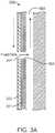
- FIG. 3Ashows a partial cross-section of an exemplary embodiment of a stage tool within a wellbore.
- Stage tool 300is placed within wellbore 500.
- the sliding sleeve 302is held within the external body 301 .
- the stage toolis shown in an open configuration with the body cement ports 303 and sleeve cement ports 304 aligned.
- the arrowsdepict the direction of fluid flow.
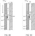
- FIGs. 3B and 3Cshow a partial cross-section of embodiment of a stage tool having a sleeve backing and a body backstop.
- Stage tool 400is shown within wellbore 500 .
- the sliding sleeve 402is held within the external body 401 .
- the stage tool 400is shown in an open configuration with the body cement ports 403 and sleeve cement ports 404 aligned.
- the arrowsdepict the direction of fluid flow.
- the sliding sleeve 402comprises a thin sleeve backing 405 on the inner side to restrain the alloy from running into the inside of the inner lumen of the tool 400 .
- the backing 405may be made of aluminum or other materials having a melting point higher than the meltable alloy. The backing 405 would thus guide the melted alloy to the desired location.
- stage tool 400did not close, it would leave a number of the circulation ports open. Open ports may not always get sealed by cement after the stage tool 400 is drilled out.
- the exterior of the external body 401 of the stage tool 400may comprise a backstop 406 positioned to shield the body cement port 403 .
- the backstop 406would prevent cooled alloy in the cement ports 403 , 404 from being blown out of the cement ports 403 , 404 during the pressure testing.
- FIG. 3Bdepicts the stage tool 400 before the meltable alloy is melted by the heat source.
- FIG. 3Cdepicts the stage tool 400 after the alloy has been melted by the heat source.
- the backing 405guides the melted alloy to the cement ports 403 , 404 where it is held in place by the backstop 406 .
Landscapes
- Life Sciences & Earth Sciences (AREA)
- Engineering & Computer Science (AREA)
- Geology (AREA)
- Mining & Mineral Resources (AREA)
- Physics & Mathematics (AREA)
- Environmental & Geological Engineering (AREA)
- Fluid Mechanics (AREA)
- General Life Sciences & Earth Sciences (AREA)
- Geochemistry & Mineralogy (AREA)
- Pressure Welding/Diffusion-Bonding (AREA)
- Sealing Using Fluids, Sealing Without Contact, And Removal Of Oil (AREA)
- Earth Drilling (AREA)
Description
- The present disclosure generally relates to a stage tool for cementing a wellbore, and in particular systems and methods for sealing stage tool leaks.
- The stage tools find its application in conventional and non-conventional wells to enable cementing long columns in two or several stages. Generally, while using cementing tools involving two stages, the tool is placed in the casing string so that the hydrostatic pressure of the cement column does not break down the formation. After the completion of first stage cementation and when the cement has gained enough strength to support hydrostatic pressure, the stage tool is opened and the cement job is performed on the upper half of the well. Many natural terrains require the aforementioned stage tool for successful cementing.
- A challenge with conventional stage tools for wellbore cementing is that the sleeves that isolate the inner casing from the annulus, once closed, may leak. This may lead to leakage of wellbore fluids and hydrocarbons to the inside of the casing, requiring remediation and increasing the cost.
- A conventional method to prevent leaking involves a cement squeeze. However, the method of cement squeezing does not have a high success rate due to the high pressure exerted at the wellbores on the set cement. Another conventional method of leak protection involves a casing patch. A casing patch requires a rig which may be expensive. Yet another conventional method of sealing uses a stub liner, which increases the complexity of the tool and also increases the cost of production. Therefore, there exists the need for improved devices, methods, and systems for sealing stage tool leaks.
EP0581533A2 describes a staged cementing tool including a cementing port which may be closed by a sliding internal sleeve.US20060114591A1 describes a method for sealing cracks in cement or in casing using a eutectic bismuth-based alloy.- According to the invention, a stage tool for wellbore cementing and a method for sealing a leak in a stage tool are provided in accordance with the appended independent claims, with optional features set out in the appended dependent claims.
- The invention has other advantages and features which will be more readily apparent from the following detailed description of the invention and the appended claims, when taken in conjunction with the accompanying drawings, in which:
FIG. 1 shows an exemplary method for sealing leaks in a stage tool.FIG. 2 shows an embodiment of a stage tool configured to seal leaks.FIGs. 3A-3C show exemplary embodiments of stage tools within a wellbore.- While the invention has been disclosed with reference to certain embodiments, it will be understood by those skilled in the art that various changes may be made and equivalents may be substituted without departing from the scope of the invention. In addition, many modifications may be made to adapt to a particular situation or material to the teachings of the invention without departing from its scope.
- Throughout the specification and claims, the following terms take the meanings explicitly associated herein unless the context clearly dictates otherwise. The meaning of "a", "an", and "the" include plural references. The meaning of "in" includes "in" and "on." Referring to the drawings, like numbers indicate like parts throughout the views. Additionally, a reference to the singular includes a reference to the plural unless otherwise stated or inconsistent with the disclosure herein.
- The word "exemplary" is used herein to mean "serving as an example, instance, or illustration." Any implementation described herein as "exemplary" is not necessarily to be construed as advantageous over other implementations.
FIG. 1 shows an exemplary method for sealing leaks in a stage tool. Atstep 101 the stage tool is provided. Examples of stage tools are described inU.S. Pat. No. 7,857,052 . The stage tool may then be used for wellbore cementing. An exemplary stage tool configured to seal leaks is shown inFIG. 2 .- In an embodiment the
stage tool 200 comprises a tubular externalstage tool body 201 with one or morebody cement ports 203 configured to deliver cement to the wellbore. Thestage tool 200 may further comprise a tubularsliding sleeve 202 within theexternal body 201 configured to regulate cement flow through thestage tool 200. The slidingsleeve 202 comprises one or morebody cement ports 204 configured to deliver cement to the wellbore. Thestage tool 200 may have a sliding sleeve, a rotational open-close sleeve, and/or an electronic, mechanical or hydraulic tool. - The
stage tool 200 may have closed and open configurations. In various embodiments,stage tool 200 may be opened or closed by free-fall dropping plugs. Alternatively,stage tool 200 may be opened or closed hydraulically. In an embodiment, thesliding sleeve 202 is configured to longitudinally slide within theexternal body 201 to move between the closed and open configurations. In the closed configuration, thesleeve cement ports 204 are longitudinally misaligned with thebody cement ports 203, thereby preventing cement flow to the wellbore. The slidingsleeve 202 may longitudinally slide within theexternal body 201 to align thesleeve cement ports 204 with thebody cement ports 203 thereby allowing the cement to be delivered to the wellbore. - While
FIG. 2 depicts a stage tool with a longitudinally sliding sleeve, other configurations may be used. In an alternative embodiment the stage tool may comprise a rotating sleeve or collar configured to transition the stage tool between open and closed configurations. In the closed configuration, the sleeve cement ports are circumferentially misaligned with the body cement ports, thereby preventing cement flow to the wellbore. The rotating sleeve may rotate within the external body to align the sleeve cement ports with the body cement ports thereby allowing the cement to be delivered to the wellbore. In other embodiments, the stage tool may be opened or closed using electronic, mechanical, or hydraulic mechanisms. - All or part of sliding
sleeve 202 of thestage tool 200 may comprise a meltable alloy configured to seal a leak. In various embodiments the meltable alloy may be a solder. In some embodiments the meltable alloy is a eutectic alloy. In an embodiment the meltable alloy is a bismuth containing alloy. The bismuth containing alloy may comprise additional metals such as germanium in order to regulate the melting temperature to a higher or lower value. Additionally or alternatively the bismuth alloy may comprise other metals such as copper, lead, tin, cadmium, indium, antimony, gallium, antimony, or silver. The proportions of bismuth and other materials in the alloy may be adjusted to reach a desired melting temperature and/or durability. For example, a bismuth alloy with a germanium percentage of less than 1% by weight increases the melting temperature to approximately 550° C from 271° C for pure bismuth. A bismuth alloy with a germanium percentage of 10% by weight increases the melting temperature to approximately 740° C. In an embodiment, the meltable alloy is a bismuth alloy with up to 20% germanium by weight, since the melting temperature of the alloy is minimally affected by increasing the percentage of germanium above 20%. - If a leak is detected, at step102 a heating source is delivered to a portion of the sliding sleeve comprising the meltable alloy and near the leak. The heating source may be any source capable of generating enough heat to melt the meltable alloy such as a chemical or electrical heater. In an embodiment, the heating source is a thermite heater. The thermite in various embodiments is selected from a mixture comprising aluminium, magnesium, titanium, zinc, silicon, or boron with oxidizers such as bismuth(III) oxide, boron(III) oxide, silicon(IV) oxide, chromium(III) oxide, manganese(IV) oxide, iron(III) oxide, iron(II,III) oxide, copper(II) oxide or lead(II,IV) oxide. A thermite with the combination of aluminium and iron oxide may be used. Thermite may be mixed with a damping agent such as sand or silica in order to reduce the temperature of the reaction. The proportions of thermite and damping agent in the heating source may be adjusted to reach a desired reaction temperature compatible with the melting temperatures of the meltable alloy and other materials in the stage tool. Thermite proportions may range from 100% to less than 1%, with the damping agent comprising the remainder of the thermite mixture. For example, the heating source may be configured to reach a temperature sufficient to melt the meltable alloy but not high enough to melt other portions of the stage tool made of materials such as aluminum, steel, etc. Examples of heating sources and meltable alloys are described in
U.S. Pat. Pub. No. 20150368542 . - At
step 103 the heating source is activated. The heating source then heats to a sufficient temperature to melt at least a portion of the meltable alloy. The slidingsleeve 202 may further comprise an aluminum backing on an inner side configured to restrain the melted alloy from flowing into an inside of the tool. Atstep 104 the melted alloy flows into the leak. - At
step 105 the heating source is removed, deactivated, or the chemical reaction is allowed to complete. The melted alloy is then allowed to cool. The melted alloy then resolidifies, thereby sealing the leak. FIG. 3A shows a partial cross-section of an exemplary embodiment of a stage tool within a wellbore.Stage tool 300 is placed withinwellbore 500. The slidingsleeve 302 is held within theexternal body 301. The stage tool is shown in an open configuration with thebody cement ports 303 andsleeve cement ports 304 aligned. The arrows depict the direction of fluid flow.FIGs. 3B and 3C show a partial cross-section of embodiment of a stage tool having a sleeve backing and a body backstop.Stage tool 400 is shown withinwellbore 500. The slidingsleeve 402 is held within theexternal body 401. Thestage tool 400 is shown in an open configuration with thebody cement ports 403 andsleeve cement ports 404 aligned. The arrows depict the direction of fluid flow. The slidingsleeve 402 comprises athin sleeve backing 405 on the inner side to restrain the alloy from running into the inside of the inner lumen of thetool 400. Thebacking 405 may be made of aluminum or other materials having a melting point higher than the meltable alloy. Thebacking 405 would thus guide the melted alloy to the desired location.- In the event that the
stage tool 400 did not close, it would leave a number of the circulation ports open. Open ports may not always get sealed by cement after thestage tool 400 is drilled out. The exterior of theexternal body 401 of thestage tool 400 may comprise abackstop 406 positioned to shield thebody cement port 403. Thebackstop 406 would prevent cooled alloy in thecement ports cement ports FIG. 3B depicts thestage tool 400 before the meltable alloy is melted by the heat source.FIG. 3C depicts thestage tool 400 after the alloy has been melted by the heat source. Thebacking 405 guides the melted alloy to thecement ports backstop 406. - Although the detailed description contains many specifics, these should not be construed as limiting the scope of the invention but merely as illustrating different examples and aspects of the invention. It should be appreciated that the scope of the invention includes other embodiments not discussed herein. Various other modifications, changes and variations which will be apparent to those skilled in the art may be made in the arrangement, operation and details of the system and method of the present invention disclosed herein without departing from the scope of the invention as defined in the claims.
- While the invention has been disclosed with reference to certain embodiments, it will be understood by those skilled in the art that various changes may be made and equivalents may be substituted without departing from the scope of the invention as defined in the claims.
Claims (12)
- A stage tool (200, 300, 400) for wellbore cementing, comprising:an external stage tool body (201, 301, 401); anda sliding sleeve (202, 302, 402) within the external stage tool body (201, 301, 401) configured to regulate flow through the stage tool (200, 300, 400);wherein the external stage tool body comprises a body cement port (203, 303, 403);characterized in that:the sliding sleeve comprises a sleeve cement port (204); and wherein the sliding sleeve (202, 302, 402) is configured to have a closed configuration wherein the body cement port (203, 303, 403) and the sleeve cement port (204, 304, 404) are not aligned, and an open configuration wherein the body cement port (203, 303, 403) and the sleeve cement port (204) are aligned;the sliding sleeve (202, 302, 402) comprises a meltable alloy configured to seal a leak; andthe meltable alloy is configured to be melted by a heating source, flow into the leak, and resolidify as the melted alloy cools, thereby sealing the leak; andthe sliding sleeve (202, 302, 402) has an aluminum backing (405) on an inner side configured to restrain the melted alloy from flowing into an inside of the tool and to guide the melted alloy through the sleeve cement port (204, 304, 404) and the body cement port (203, 303, 403) to a backstop (406) on the external stage tool body.
- The stage tool of claim 1, wherein the meltable alloy is a bismuth-containing alloy.
- The stage tool of claim 2, wherein the bismuth-containing alloy comprises germanium, optionally wherein the bismuth-containing alloy further comprises copper, lead, tin, cadmium, indium, antimony, gallium, antimony, or silver.
- The stage tool of claim 1, wherein the meltable alloy is a solder.
- The stage tool of claim 1, wherein the meltable alloy is a eutectic alloy.
- The stage tool of claim 1, wherein the heating source is a thermite heater.
- The stage tool of claim 1, wherein the heating source comprises a damping agent.
- The stage tool of claim 7, wherein the backstop (406) is positioned to shield the body cement port (203, 303, 403) and prevent cooled alloy from blowing out of the body cement port (203, 303, 403) during pressure testing.
- A method of sealing a leak in a stage tool, using a stage tool (200, 300, 400) as claimed in any preceding claim, the method comprising:delivering a heating source to the stage tool (200, 300, 400) having a leak;melting a portion of the sliding sleeve (202, 302, 402) using the heating source, wherein the portion of the sliding sleeve (202, 302, 402) comprises a meltable alloy configured to seal the leak;causing the melted alloy to flow into the leak; andresolidifying the alloy thereby sealing the leak;the method further comprising guiding the melted alloy to the location of the leak and confining the molted alloy at the location of the leak using the backing sleeve (405) or backstop fixture (406).
- The method of claim 9, wherein the meltable alloy is a bismuth-containing alloy, optionally wherein the bismuth-containing alloy comprises germanium.
- The method of claim 9, wherein the heating source is a thermite heater.
- The method of claim 9, wherein the heating source comprises a damping agent.
Applications Claiming Priority (2)
| Application Number | Priority Date | Filing Date | Title |
|---|---|---|---|
| US201762526708P | 2017-06-29 | 2017-06-29 | |
| PCT/US2018/040048WO2019006141A1 (en) | 2017-06-29 | 2018-06-28 | Methods, systems, and devices for sealing stage tool leaks |
Publications (3)
| Publication Number | Publication Date |
|---|---|
| EP3645824A1 EP3645824A1 (en) | 2020-05-06 |
| EP3645824A4 EP3645824A4 (en) | 2020-06-03 |
| EP3645824B1true EP3645824B1 (en) | 2021-06-02 |
Family
ID=64737914
Family Applications (1)
| Application Number | Title | Priority Date | Filing Date |
|---|---|---|---|
| EP18823434.8AActiveEP3645824B1 (en) | 2017-06-29 | 2018-06-28 | Methods, systems, and devices for sealing stage tool leaks |
Country Status (4)
| Country | Link |
|---|---|
| US (1) | US10550663B2 (en) |
| EP (1) | EP3645824B1 (en) |
| CA (1) | CA3070391C (en) |
| WO (1) | WO2019006141A1 (en) |
Families Citing this family (8)
| Publication number | Priority date | Publication date | Assignee | Title |
|---|---|---|---|---|
| GB2594198B (en)* | 2019-01-10 | 2022-07-20 | Isol8 Holdings Ltd | Downhole method and apparatus |
| GB2580587B (en)* | 2019-01-10 | 2021-10-13 | Isol8 Holdings Ltd | Downhole method and apparatus |
| US11371623B2 (en)* | 2019-09-18 | 2022-06-28 | Saudi Arabian Oil Company | Mechanisms and methods for closure of a flow control device |
| US11118423B1 (en)* | 2020-05-01 | 2021-09-14 | Halliburton Energy Services, Inc. | Downhole tool for use in a borehole |
| US11549323B2 (en) | 2020-05-20 | 2023-01-10 | Halliburton Energy Services, Inc. | Systems and methods for bonding a downhole tool to a borehole tubular |
| US11339621B2 (en) | 2020-05-20 | 2022-05-24 | Halliburton Energy Services, Inc. | Systems and methods for bonding a downhole tool to a surface within the borehole |
| US12305484B2 (en)* | 2022-11-01 | 2025-05-20 | Halliburton Energy Services, Inc. | Pre-positioning a meltable seal for plug and abandonment |
| US12247465B2 (en) | 2023-05-31 | 2025-03-11 | Saudi Arabian Oil Company | Method and apparatus for curing loss-of-circulation in oil and gas wells with a eutectic alloy expandable patch |
Family Cites Families (15)
| Publication number | Priority date | Publication date | Assignee | Title |
|---|---|---|---|---|
| US1912578A (en)* | 1931-11-10 | 1933-06-06 | Halliburton Erle Palmer | Method of and apparatus for recovering fluids from underground strata |
| US3578084A (en)* | 1969-06-23 | 1971-05-11 | Exxon Production Research Co | Thermal well completion method and apparatus |
| US5314015A (en) | 1992-07-31 | 1994-05-24 | Halliburton Company | Stage cementer and inflation packer apparatus |
| US5479986A (en)* | 1994-05-02 | 1996-01-02 | Halliburton Company | Temporary plug system |
| US6474414B1 (en)* | 2000-03-09 | 2002-11-05 | Texaco, Inc. | Plug for tubulars |
| GB2382365B (en) | 2001-11-27 | 2004-04-14 | Schlumberger Holdings | Leak remedy through sealants in local reservoirs |
| JP2006155746A (en) | 2004-11-29 | 2006-06-15 | Fujitsu Ltd | Magnetic recording method |
| US20060144591A1 (en)* | 2004-12-30 | 2006-07-06 | Chevron U.S.A. Inc. | Method and apparatus for repair of wells utilizing meltable repair materials and exothermic reactants as heating agents |
| GB2451784B (en) | 2006-05-12 | 2011-06-01 | Weatherford Lamb | Stage cementing methods used in casing while drilling |
| GB2480869B (en)* | 2010-06-04 | 2017-01-11 | Bisn Tec Ltd | Method and apparatus for use in well abandonment |
| GB201223055D0 (en) | 2012-12-20 | 2013-02-06 | Carragher Paul | Method and apparatus for use in well abandonment |
| US9856714B2 (en)* | 2013-07-17 | 2018-01-02 | Weatherford Technology Holdings, Llc | Zone select stage tool system |
| US9447655B2 (en)* | 2013-10-15 | 2016-09-20 | Baker Hughes Incorporated | Methods for hanging liner from casing and articles derived therefrom |
| GB201414565D0 (en)* | 2014-08-15 | 2014-10-01 | Bisn Oil Tools Ltd | Methods and apparatus for use in oil and gas well completion |
| EP3029261B1 (en)* | 2014-12-02 | 2019-05-22 | Services Pétroliers Schlumberger | Methods of deployment for eutectic isolation tools to ensure wellbore plugs |
- 2018
- 2018-06-28EPEP18823434.8Apatent/EP3645824B1/enactiveActive
- 2018-06-28CACA3070391Apatent/CA3070391C/enactiveActive
- 2018-06-28USUS16/021,916patent/US10550663B2/enactiveActive
- 2018-06-28WOPCT/US2018/040048patent/WO2019006141A1/ennot_activeCeased
Also Published As
| Publication number | Publication date |
|---|---|
| US10550663B2 (en) | 2020-02-04 |
| EP3645824A4 (en) | 2020-06-03 |
| WO2019006141A1 (en) | 2019-01-03 |
| CA3070391A1 (en) | 2019-01-03 |
| CA3070391C (en) | 2024-01-02 |
| EP3645824A1 (en) | 2020-05-06 |
| US20190003282A1 (en) | 2019-01-03 |
Similar Documents
| Publication | Publication Date | Title |
|---|---|---|
| EP3645824B1 (en) | Methods, systems, and devices for sealing stage tool leaks | |
| US11536111B2 (en) | Downhole tool deployment assembly with improved heater removability and methods of employing such | |
| CA2864808C (en) | Well abandonment by melting surrounding materials | |
| CN103459765B (en) | Drilled metal component joining system and method thereof | |
| US11098553B2 (en) | Method for sealing a region of open hole gravel pack | |
| Carragher et al. | Well abandonment solutions utilizing bismuth and thermite | |
| EP3940195B1 (en) | Removable plugging method and apparatus | |
| Fulks et al. | A new solution for well abandonment: Bismuth and thermite | |
| Fulks et al. | Bismuth abandonment plugs: The possibilities are endless | |
| EP3631150B1 (en) | A downhole tool deployment assembly with improved heater removability and methods of employing such | |
| Carragher et al. | Rigless abandonment with bismuth and thermite | |
| US11371623B2 (en) | Mechanisms and methods for closure of a flow control device | |
| Fulks et al. | Alternative abandonment material: bismuth | |
| US12338713B2 (en) | One trip system to set an alloy seal and mill through | |
| US20240263537A1 (en) | Downhole millable permanent plug and method for setting a downhole millable permanent plug | |
| WO2016069596A1 (en) | Eutectic casing window |
Legal Events
| Date | Code | Title | Description |
|---|---|---|---|
| STAA | Information on the status of an ep patent application or granted ep patent | Free format text:STATUS: THE INTERNATIONAL PUBLICATION HAS BEEN MADE | |
| PUAI | Public reference made under article 153(3) epc to a published international application that has entered the european phase | Free format text:ORIGINAL CODE: 0009012 | |
| STAA | Information on the status of an ep patent application or granted ep patent | Free format text:STATUS: REQUEST FOR EXAMINATION WAS MADE | |
| 17P | Request for examination filed | Effective date:20200120 | |
| AK | Designated contracting states | Kind code of ref document:A1 Designated state(s):AL AT BE BG CH CY CZ DE DK EE ES FI FR GB GR HR HU IE IS IT LI LT LU LV MC MK MT NL NO PL PT RO RS SE SI SK SM TR | |
| AX | Request for extension of the european patent | Extension state:BA ME | |
| STAA | Information on the status of an ep patent application or granted ep patent | Free format text:STATUS: EXAMINATION IS IN PROGRESS | |
| A4 | Supplementary search report drawn up and despatched | Effective date:20200507 | |
| RIC1 | Information provided on ipc code assigned before grant | Ipc:E21B 33/04 20060101ALI20200429BHEP Ipc:E21B 23/00 20060101ALI20200429BHEP Ipc:E21B 34/00 20060101ALI20200429BHEP Ipc:E21B 33/12 20060101ALI20200429BHEP Ipc:E21B 33/10 20060101ALI20200429BHEP Ipc:E21B 17/02 20060101AFI20200429BHEP | |
| 17Q | First examination report despatched | Effective date:20200518 | |
| DAV | Request for validation of the european patent (deleted) | ||
| DAX | Request for extension of the european patent (deleted) | ||
| GRAP | Despatch of communication of intention to grant a patent | Free format text:ORIGINAL CODE: EPIDOSNIGR1 | |
| STAA | Information on the status of an ep patent application or granted ep patent | Free format text:STATUS: GRANT OF PATENT IS INTENDED | |
| INTG | Intention to grant announced | Effective date:20210223 | |
| GRAS | Grant fee paid | Free format text:ORIGINAL CODE: EPIDOSNIGR3 | |
| GRAA | (expected) grant | Free format text:ORIGINAL CODE: 0009210 | |
| STAA | Information on the status of an ep patent application or granted ep patent | Free format text:STATUS: THE PATENT HAS BEEN GRANTED | |
| REG | Reference to a national code | Ref country code:CH Ref legal event code:EP | |
| AK | Designated contracting states | Kind code of ref document:B1 Designated state(s):AL AT BE BG CH CY CZ DE DK EE ES FI FR GB GR HR HU IE IS IT LI LT LU LV MC MK MT NL NO PL PT RO RS SE SI SK SM TR | |
| REG | Reference to a national code | Ref country code:GB Ref legal event code:FG4D | |
| REG | Reference to a national code | Ref country code:AT Ref legal event code:REF Ref document number:1398578 Country of ref document:AT Kind code of ref document:T Effective date:20210615 | |
| REG | Reference to a national code | Ref country code:IE Ref legal event code:FG4D | |
| REG | Reference to a national code | Ref country code:DE Ref legal event code:R096 Ref document number:602018018183 Country of ref document:DE | |
| REG | Reference to a national code | Ref country code:NO Ref legal event code:T2 Effective date:20210602 | |
| REG | Reference to a national code | Ref country code:LT Ref legal event code:MG9D | |
| PG25 | Lapsed in a contracting state [announced via postgrant information from national office to epo] | Ref country code:BG Free format text:LAPSE BECAUSE OF FAILURE TO SUBMIT A TRANSLATION OF THE DESCRIPTION OR TO PAY THE FEE WITHIN THE PRESCRIBED TIME-LIMIT Effective date:20210902 Ref country code:FI Free format text:LAPSE BECAUSE OF FAILURE TO SUBMIT A TRANSLATION OF THE DESCRIPTION OR TO PAY THE FEE WITHIN THE PRESCRIBED TIME-LIMIT Effective date:20210602 Ref country code:HR Free format text:LAPSE BECAUSE OF FAILURE TO SUBMIT A TRANSLATION OF THE DESCRIPTION OR TO PAY THE FEE WITHIN THE PRESCRIBED TIME-LIMIT Effective date:20210602 Ref country code:LT Free format text:LAPSE BECAUSE OF FAILURE TO SUBMIT A TRANSLATION OF THE DESCRIPTION OR TO PAY THE FEE WITHIN THE PRESCRIBED TIME-LIMIT Effective date:20210602 | |
| REG | Reference to a national code | Ref country code:NL Ref legal event code:MP Effective date:20210602 | |
| REG | Reference to a national code | Ref country code:AT Ref legal event code:MK05 Ref document number:1398578 Country of ref document:AT Kind code of ref document:T Effective date:20210602 | |
| PG25 | Lapsed in a contracting state [announced via postgrant information from national office to epo] | Ref country code:GR Free format text:LAPSE BECAUSE OF FAILURE TO SUBMIT A TRANSLATION OF THE DESCRIPTION OR TO PAY THE FEE WITHIN THE PRESCRIBED TIME-LIMIT Effective date:20210903 Ref country code:SE Free format text:LAPSE BECAUSE OF FAILURE TO SUBMIT A TRANSLATION OF THE DESCRIPTION OR TO PAY THE FEE WITHIN THE PRESCRIBED TIME-LIMIT Effective date:20210602 Ref country code:RS Free format text:LAPSE BECAUSE OF FAILURE TO SUBMIT A TRANSLATION OF THE DESCRIPTION OR TO PAY THE FEE WITHIN THE PRESCRIBED TIME-LIMIT Effective date:20210602 Ref country code:LV Free format text:LAPSE BECAUSE OF FAILURE TO SUBMIT A TRANSLATION OF THE DESCRIPTION OR TO PAY THE FEE WITHIN THE PRESCRIBED TIME-LIMIT Effective date:20210602 Ref country code:PL Free format text:LAPSE BECAUSE OF FAILURE TO SUBMIT A TRANSLATION OF THE DESCRIPTION OR TO PAY THE FEE WITHIN THE PRESCRIBED TIME-LIMIT Effective date:20210602 | |
| REG | Reference to a national code | Ref country code:DE Ref legal event code:R119 Ref document number:602018018183 Country of ref document:DE | |
| PG25 | Lapsed in a contracting state [announced via postgrant information from national office to epo] | Ref country code:AT Free format text:LAPSE BECAUSE OF FAILURE TO SUBMIT A TRANSLATION OF THE DESCRIPTION OR TO PAY THE FEE WITHIN THE PRESCRIBED TIME-LIMIT Effective date:20210602 Ref country code:CZ Free format text:LAPSE BECAUSE OF FAILURE TO SUBMIT A TRANSLATION OF THE DESCRIPTION OR TO PAY THE FEE WITHIN THE PRESCRIBED TIME-LIMIT Effective date:20210602 Ref country code:SM Free format text:LAPSE BECAUSE OF FAILURE TO SUBMIT A TRANSLATION OF THE DESCRIPTION OR TO PAY THE FEE WITHIN THE PRESCRIBED TIME-LIMIT Effective date:20210602 Ref country code:PT Free format text:LAPSE BECAUSE OF FAILURE TO SUBMIT A TRANSLATION OF THE DESCRIPTION OR TO PAY THE FEE WITHIN THE PRESCRIBED TIME-LIMIT Effective date:20211004 Ref country code:NL Free format text:LAPSE BECAUSE OF FAILURE TO SUBMIT A TRANSLATION OF THE DESCRIPTION OR TO PAY THE FEE WITHIN THE PRESCRIBED TIME-LIMIT Effective date:20210602 Ref country code:RO Free format text:LAPSE BECAUSE OF FAILURE TO SUBMIT A TRANSLATION OF THE DESCRIPTION OR TO PAY THE FEE WITHIN THE PRESCRIBED TIME-LIMIT Effective date:20210602 Ref country code:SK Free format text:LAPSE BECAUSE OF FAILURE TO SUBMIT A TRANSLATION OF THE DESCRIPTION OR TO PAY THE FEE WITHIN THE PRESCRIBED TIME-LIMIT Effective date:20210602 Ref country code:ES Free format text:LAPSE BECAUSE OF FAILURE TO SUBMIT A TRANSLATION OF THE DESCRIPTION OR TO PAY THE FEE WITHIN THE PRESCRIBED TIME-LIMIT Effective date:20210602 Ref country code:EE Free format text:LAPSE BECAUSE OF FAILURE TO SUBMIT A TRANSLATION OF THE DESCRIPTION OR TO PAY THE FEE WITHIN THE PRESCRIBED TIME-LIMIT Effective date:20210602 | |
| REG | Reference to a national code | Ref country code:CH Ref legal event code:PL | |
| REG | Reference to a national code | Ref country code:BE Ref legal event code:MM Effective date:20210630 | |
| PG25 | Lapsed in a contracting state [announced via postgrant information from national office to epo] | Ref country code:MC Free format text:LAPSE BECAUSE OF FAILURE TO SUBMIT A TRANSLATION OF THE DESCRIPTION OR TO PAY THE FEE WITHIN THE PRESCRIBED TIME-LIMIT Effective date:20210602 Ref country code:LU Free format text:LAPSE BECAUSE OF NON-PAYMENT OF DUE FEES Effective date:20210628 | |
| PLBE | No opposition filed within time limit | Free format text:ORIGINAL CODE: 0009261 | |
| STAA | Information on the status of an ep patent application or granted ep patent | Free format text:STATUS: NO OPPOSITION FILED WITHIN TIME LIMIT | |
| PG25 | Lapsed in a contracting state [announced via postgrant information from national office to epo] | Ref country code:LI Free format text:LAPSE BECAUSE OF NON-PAYMENT OF DUE FEES Effective date:20210630 Ref country code:IE Free format text:LAPSE BECAUSE OF NON-PAYMENT OF DUE FEES Effective date:20210628 Ref country code:DK Free format text:LAPSE BECAUSE OF FAILURE TO SUBMIT A TRANSLATION OF THE DESCRIPTION OR TO PAY THE FEE WITHIN THE PRESCRIBED TIME-LIMIT Effective date:20210602 Ref country code:DE Free format text:LAPSE BECAUSE OF NON-PAYMENT OF DUE FEES Effective date:20220101 Ref country code:CH Free format text:LAPSE BECAUSE OF NON-PAYMENT OF DUE FEES Effective date:20210630 | |
| 26N | No opposition filed | Effective date:20220303 | |
| PG25 | Lapsed in a contracting state [announced via postgrant information from national office to epo] | Ref country code:FR Free format text:LAPSE BECAUSE OF NON-PAYMENT OF DUE FEES Effective date:20210802 Ref country code:AL Free format text:LAPSE BECAUSE OF FAILURE TO SUBMIT A TRANSLATION OF THE DESCRIPTION OR TO PAY THE FEE WITHIN THE PRESCRIBED TIME-LIMIT Effective date:20210602 | |
| PG25 | Lapsed in a contracting state [announced via postgrant information from national office to epo] | Ref country code:IT Free format text:LAPSE BECAUSE OF FAILURE TO SUBMIT A TRANSLATION OF THE DESCRIPTION OR TO PAY THE FEE WITHIN THE PRESCRIBED TIME-LIMIT Effective date:20210602 Ref country code:BE Free format text:LAPSE BECAUSE OF NON-PAYMENT OF DUE FEES Effective date:20210630 | |
| PG25 | Lapsed in a contracting state [announced via postgrant information from national office to epo] | Ref country code:CY Free format text:LAPSE BECAUSE OF FAILURE TO SUBMIT A TRANSLATION OF THE DESCRIPTION OR TO PAY THE FEE WITHIN THE PRESCRIBED TIME-LIMIT Effective date:20210602 | |
| PG25 | Lapsed in a contracting state [announced via postgrant information from national office to epo] | Ref country code:HU Free format text:LAPSE BECAUSE OF FAILURE TO SUBMIT A TRANSLATION OF THE DESCRIPTION OR TO PAY THE FEE WITHIN THE PRESCRIBED TIME-LIMIT; INVALID AB INITIO Effective date:20180628 | |
| P01 | Opt-out of the competence of the unified patent court (upc) registered | Effective date:20231207 | |
| PG25 | Lapsed in a contracting state [announced via postgrant information from national office to epo] | Ref country code:MK Free format text:LAPSE BECAUSE OF FAILURE TO SUBMIT A TRANSLATION OF THE DESCRIPTION OR TO PAY THE FEE WITHIN THE PRESCRIBED TIME-LIMIT Effective date:20210602 | |
| PG25 | Lapsed in a contracting state [announced via postgrant information from national office to epo] | Ref country code:MT Free format text:LAPSE BECAUSE OF FAILURE TO SUBMIT A TRANSLATION OF THE DESCRIPTION OR TO PAY THE FEE WITHIN THE PRESCRIBED TIME-LIMIT Effective date:20210602 | |
| PGFP | Annual fee paid to national office [announced via postgrant information from national office to epo] | Ref country code:GB Payment date:20250520 Year of fee payment:8 | |
| PGFP | Annual fee paid to national office [announced via postgrant information from national office to epo] | Ref country code:NO Payment date:20250522 Year of fee payment:8 |