EP3639698A1 - Seat support for a chair and chair comprising such a seat support - Google Patents
Seat support for a chair and chair comprising such a seat supportDownload PDFInfo
- Publication number
- EP3639698A1 EP3639698A1EP19204101.0AEP19204101AEP3639698A1EP 3639698 A1EP3639698 A1EP 3639698A1EP 19204101 AEP19204101 AEP 19204101AEP 3639698 A1EP3639698 A1EP 3639698A1
- Authority
- EP
- European Patent Office
- Prior art keywords
- locking
- seat support
- locking mechanism
- support part
- release position
- Prior art date
- Legal status (The legal status is an assumption and is not a legal conclusion. Google has not performed a legal analysis and makes no representation as to the accuracy of the status listed.)
- Granted
Links
Images


Classifications
- A—HUMAN NECESSITIES
- A47—FURNITURE; DOMESTIC ARTICLES OR APPLIANCES; COFFEE MILLS; SPICE MILLS; SUCTION CLEANERS IN GENERAL
- A47C—CHAIRS; SOFAS; BEDS
- A47C3/00—Chairs characterised by structural features; Chairs or stools with rotatable or vertically-adjustable seats
- A47C3/02—Rocking chairs
- A47C3/03—Locking members
- A—HUMAN NECESSITIES
- A47—FURNITURE; DOMESTIC ARTICLES OR APPLIANCES; COFFEE MILLS; SPICE MILLS; SUCTION CLEANERS IN GENERAL
- A47C—CHAIRS; SOFAS; BEDS
- A47C3/00—Chairs characterised by structural features; Chairs or stools with rotatable or vertically-adjustable seats
- A47C3/02—Rocking chairs
- A47C3/025—Rocking chairs with seat, or seat and back-rest unit elastically or pivotally mounted in a rigid base frame
- A47C3/0252—Rocking chairs with seat, or seat and back-rest unit elastically or pivotally mounted in a rigid base frame connected only by an elastic member positioned between seat and base frame
- A—HUMAN NECESSITIES
- A47—FURNITURE; DOMESTIC ARTICLES OR APPLIANCES; COFFEE MILLS; SPICE MILLS; SUCTION CLEANERS IN GENERAL
- A47C—CHAIRS; SOFAS; BEDS
- A47C3/00—Chairs characterised by structural features; Chairs or stools with rotatable or vertically-adjustable seats
- A47C3/02—Rocking chairs
- A47C3/025—Rocking chairs with seat, or seat and back-rest unit elastically or pivotally mounted in a rigid base frame
- A47C3/026—Rocking chairs with seat, or seat and back-rest unit elastically or pivotally mounted in a rigid base frame with central column, e.g. rocking office chairs; Tilting chairs
- A—HUMAN NECESSITIES
- A47—FURNITURE; DOMESTIC ARTICLES OR APPLIANCES; COFFEE MILLS; SPICE MILLS; SUCTION CLEANERS IN GENERAL
- A47C—CHAIRS; SOFAS; BEDS
- A47C7/00—Parts, details, or accessories of chairs or stools
- A47C7/02—Seat parts
- A47C7/14—Seat parts of adjustable shape; elastically mounted ; adaptable to a user contour or ergonomic seating positions
- A—HUMAN NECESSITIES
- A47—FURNITURE; DOMESTIC ARTICLES OR APPLIANCES; COFFEE MILLS; SPICE MILLS; SUCTION CLEANERS IN GENERAL
- A47C—CHAIRS; SOFAS; BEDS
- A47C7/00—Parts, details, or accessories of chairs or stools
- A47C7/02—Seat parts
- A47C7/34—Seat parts with springs in compression, e.g. coiled
- A47C7/345—Seat parts with springs in compression, e.g. coiled of adjustable resilience
- A—HUMAN NECESSITIES
- A47—FURNITURE; DOMESTIC ARTICLES OR APPLIANCES; COFFEE MILLS; SPICE MILLS; SUCTION CLEANERS IN GENERAL
- A47C—CHAIRS; SOFAS; BEDS
- A47C9/00—Stools for specified purposes
- A47C9/002—Stools for specified purposes with exercising means or having special therapeutic or ergonomic effects
Definitions
- the inventionrelates to a seat support for a chair and a chair with such a seat support.
- a seat support for a chairwhich has a base support part.
- Such a basic support partis typically set up to either set up the seat support or to connect the seat support to a set-up part for setting up the seat support.
- the seat supportalso has a seat support part which is set up to arrange a seat cushion on or on the seat support part.
- the seat support partis arranged between a first elastic element and a second elastic element, the first elastic element being supported on the base support part and the second elastic element on a counter bearing.
- the tilting movements of the seat support part relative to the base support partrequire permanent compensation, and thus permanent movement of the user. This is not appreciated by all users or not in every situation. Even if a user would appreciate the tilting movements in some situations, but in other situations he does not want such tilting movements, he may decide against a chair with such a seat support.
- the inventionis therefore based on the object of providing a seat support for a chair and a chair having such a seat support, the disadvantages mentioned not occurring.
- a seat support of the type mentioned abovehas a locking mechanism which can be displaced and set up between a locking position and a release position in order to lock an elastic displacement of the seat support part relative to the base support part in the locking position, and in the release position to release elastic displacement of the seat support part relative to the base support part.
- a locking mechanismwhich can be displaced and set up between a locking position and a release position in order to lock an elastic displacement of the seat support part relative to the base support part in the locking position, and in the release position to release elastic displacement of the seat support part relative to the base support part.
- the basic support partis set up to either set up the seat support or to connect the seat support to an installation part.
- the base support partitself is designed as a foot frame of a chair, in particular as a star base, preferably with preferably five arms, on the free ends of which rollers or sliding elements are provided, and which together hold a support tube in the region of their opposite common ends, which then carries the seat support part.
- the base support parthas a gas spring, in particular for height adjustment of the chair.
- the base support partcan be set up to be connected to a set-up part which is designed in particular as a base frame, preferably as a base.
- a base framepreferably has five arms, on the free ends of which rollers or sliding elements are provided, and which together hold a support tube in the region of their opposite common ends, which then carries the basic supporting part.
- the base frameit is possible for the base frame to have a gas spring for height adjustment of the chair, in which case the base support part is preferably mechanically connectable or connected to the gas spring.
- the base support partpreferably has a connection geometry for connection to the set-up part, in particular an inner cone, which is plugged onto an outer cone of the set-up part, particularly preferably an outer cone of a gas spring.
- connection geometryfor connection to the set-up part, in particular an inner cone, which is plugged onto an outer cone of the set-up part, particularly preferably an outer cone of a gas spring.
- the base support partit is possible for the base support part to be screwed to the set-up part or to be fastened to it in another suitable manner.
- the seat supportis especially designed for use in an office chair.
- the advantages of the seat supportresult in a special way here, in particular due to the high daily useful life of such an office chair by its user.
- the seat support partis preferably set up to arrange a seat cushion indirectly - mediated via at least one further part - or directly on the seat support part.
- the seat cushioncan be attached to the seat support part, preferably by screwing.
- the seat support partpreferably has at least one screw hole, preferably a plurality of screw holes, in order to fasten the seat cushion to the seat support part.
- the seat support partis designed to accommodate a chair mechanism, the chair mechanism in particular having a synchronous mechanism for synchronously tilting a seat back together with the seat support part about a horizontal axis, in particular in order to enable a user to sit backwards with the seat cushion and the seat back to lean back.
- the chair mechanismalso preferably has a mechanism for setting a pretension for this tilting movement.
- the chair mechanismpreferably has a mechanism that allows this tilting movement to be blocked.
- the seat support partis made of die-cast, in particular aluminum die-cast. But it is also possible that the seat support part is made of a plastic or another suitable material. It preferably has at least one cavity and bores for receiving the chair mechanism.
- the seat support partis arranged in particular in the vertical direction - that is to say in the axial direction - of the seat support between the first elastic element and the second elastic element, in particular clamped between the first elastic element and the second elastic element.
- a vertical directioncorresponds to a direction that at intended orientation of the seat support is oriented vertically, the vertical direction preferably being the vertical direction of a chair which has the seat carrier.
- At least one elastic element selected from the first elastic element and the second elastic elementis preferably prestressed. Both elastic elements are preferably prestressed in order to adjust the restoring forces acting against the elastic tilting movement of the seat support part relative to the base support part.
- the first elastic elementis preferably supported on one side, in particular on its underside, on the base support part, and on its other, opposite side in the vertical direction, in particular its top side, on the seat support part.
- the second elastic elementis preferably supported on one side, in particular the upper side, on the counter bearing and on its other, opposite side, in particular the lower side, on the seat support part.
- the counter bearingis preferably applied to the base support part, in particular fastened to the base support part, preferably screwed onto the base support part, the pretensioning of at least the second elastic element, preferably both elastic elements, being able to be adjusted in particular by adjusting the torque when the counter support is screwed onto the base support part .
- the counter bearingis particularly preferably screwed onto the inner cone, with which the seat support can be placed on the installation part.
- the inner conepreferably has an external thread that meshes with an internal thread of the counter bearing.
- the counter bearingis designed as a nut.
- the locking mechanismis preferably set up to lock at least one elastic element, selected from the first elastic element and the second elastic element, that is to prevent elastic deformation, in particular bending.
- the locking mechanismpreferably locks the first elastic element and the second elastic element at the same time.
- At least one elastic elementselected from the first elastic element and the second elastic element, is preferably designed as an elastomer or formed from an elastomer. Both elastic elements are particularly preferably designed as elastomers, or formed from one elastomer, or from different elastomers. In this way, the elastic elements can be provided in a simple, space-saving and inexpensive manner.
- the locking mechanismcan only be displaced into the locking position or into the release position.
- the locking mechanismthus has exactly two discrete states between which it can be shifted, but no intermediate positions between the locking position and the release position. In this way, the locking mechanism is particularly simple and intuitive to use, and it is possible to quickly switch between the locking position and the release position.
- the locking mechanismhas an axially displaceable locking ring, that is to say in the vertical direction, which preferably surrounds the first elastic element in a ring-shaped manner, in particular concentrically, in the locking position, preferably spaced apart in the release position - in the vertical direction is arranged by the first elastic element.
- the first elastic elementcan be locked very easily, stably and securely by the locking mechanism.
- the locking mechanismpreferably the locking ring
- the locking mechanismin particular the locking ring
- the locking mechanismparticularly preferably strikes the movable element of the seat carrier and holds it in a fixed position, so that mobility is prevented.
- the locking mechanismin particular the locking ring, is preferably spaced from the seat support part so that it can be tilted freely.
- the locking mechanismpreferably the locking ring
- the locking mechanismis held on the base support part.
- the locking mechanismin particular the locking ring
- the locking mechanismis preferably arranged on the fixed part of the seat support, so that forces in the locked position are introduced into the base support part as a fixed part and are absorbed there.
- the locking mechanismpreferably the locking ring
- a stopcan be done in a simple manner of the locking ring in the locking position on the seat support part, the locking ring being spaced from the seat support part in the release position.
- the locking ring on the base support partis particularly preferably held so as to be axially displaceable and abuts the seat support part in the locked position, being spaced apart from the seat support part in the release position.
- the locking ringpreferably surrounds the first elastic element in a ring-shaped manner, in particular concentrically, in the locking position, wherein it is arranged axially spaced from the first elastic element in the release position.
- the seat support parthas a support body which is set up to arrange a seat cushion on the support body, the seat support part also having a stop part, the stop part - viewed in the vertical direction - arranged under the support body, in particular fastened, preferably screwed.
- the locking mechanismin particular the locking ring, preferably strikes the stop part in the locking position.
- the stop partis designed as a stop plate.
- the stop partin particular the stop plate, is preferably arranged between the support body and the first elastic element, the stop part projecting beyond the first elastic element in all directions in the radial direction, that is to say perpendicular to the vertical direction.
- the stop partencompasses the first elastic element, seen in the circumferential direction, with an edge that is bent over in the vertical direction — downward — and encircles in the circumferential direction.
- the stop partis particularly preferably annular, in particular circular.
- the locking mechanism on a first partwhich is selected from the locking ring and the base support part, has a guide groove running at least in regions along a helical line section, and on a second part, which is selected from the base support part and the locking ring , has a guide projection, the guide projection engaging in the guide groove and being guided in the guide groove.
- the first part and the second partare different from each other.
- the first partis the locking ring when the second part is the basic supporting part, and vice versa.
- the first partis the locking ring
- the second partis the base support part, so that the guide groove is formed on the lock ring and the guide projection is arranged on the base support part.
- one end of each of the two ends of the guide grooveis assigned to one of the functional positions, so that a relative displacement between the guide projection and the guide groove can always take place completely up to the respective end of the guide groove in order to achieve the respective functional position.
- the two functional positionsare thus precisely defined.
- the helical section-shaped guide groovepreferably extends in the circumferential direction - in particular when viewed on a horizontal plane along a circumferential line - along an angular range of at least 40 ° to at most 100 °, preferably from at least 50 ° to at most 90 °, preferably from at least 60 ° to at most 90 °, preferably from at least 70 ° to at most 85 °, preferably from at least 75 ° to at most 85 °, preferably from 80 °.
- a horizontal planeis in particular a plane on which the vertical direction is perpendicular.
- a horizontal lineis accordingly, in particular, an axis in a horizontal plane, which includes a right angle with the vertical direction.
- the first partpreferably has two guide grooves or three guide grooves, and preferably the second part has two guide projections or three guide projections, each guide groove preferably being assigned a guide projection which engages in the respective guide groove.
- the guide projectionsare preferably offset from one another in the circumferential direction by 180 ° - in the case of two guide projections - or by 120 ° - in the case of three guide projections - and particularly preferably in the same axial direction Altitude arranged to each other.
- the guide groovesare preferably arranged diametrically opposite one another or offset by 120 ° to one another, wherein they are preferably arranged at the same height with one another, in particular in relation to equivalent points of the guide grooves. In particular, the ends of the guide grooves are each arranged at the same height.
- the guide groovehas a flattened groove outlet at least at its end facing the blocking position.
- “Flattened”means that the guide groove in the area of the groove outlet has a smaller slope than outside the groove outlet, the guide groove in the area of the groove outlet enclosing a smaller angle, in particular with a horizontal, than outside the groove outlet.
- the locking ringcan be held simply, securely and stably in the locking position by arranging the guide projection in the flattened slot outlet, with no or only a small force - in particular less than the static friction in the slot outlet - acting in the locking position, which pushes the locking ring into the release position.
- the groove outletcloses with the horizontal preferably an angle of at least 1 ° to at most 10 °, preferably up to at most 7 °, preferably up to at most 5 °, preferably up to at most 4 °, preferably up to at most 3 °, preferably from at least 1.5 ° to at most 2.5 °, preferably 2 °.
- the slot outletit is also possible for the slot outlet to be designed as a horizontal slot outlet, parallel to the horizontal.
- the guide groovealso has a flattened groove outlet at its end facing the release position.
- a detent positioncan be formed there in particular, or the guide groove ends without a groove outlet, that is to say in particular without changing its slope.
- the guide groovehas an incline in its helical section-shaped area, at which no self-locking of the guide projection occurs in the guide groove. This results in a particularly easy, low-friction displacement of the locking ring in the helical portion-shaped area between the locking position and the release position.
- a self-locking feature hereis a configuration of the guide groove-shaped region of the guide groove, preferably avoided, according to the invention, with a To understand slope, in which the static friction between the guide projection and the guide groove would always be greater than a force acting along the slope, for example downhill force, so that in particular no automatic displacement of the locking ring would be possible.
- no self-lockingis preferably provided in this area, which means that the slope of the area in the form of a helical section is selected such that, in particular, a force in the guide groove that forces into the release position is always greater than the static friction between the guide projection and the guide groove.
- the guide groovecloses - outside the groove outlet - preferably an angle with the horizontal of at least 11 ° to at most 20 °, preferably from at least 12 ° to at most 19 °, preferably from at least 13 ° to at most 18 °, preferably from at most 17 °, preferably from at least 14 ° to at most 16 °, preferably 15 °.
- an axial position of the locking ring on the base support partcan be adjusted in the release position.
- the locking mechanism as a whole, in particular the guide projection and the guide groovecan preferably be displaced together in the axial direction, so that the stroke of the locking ring is not changed when its axial position is changed in the release position.
- a force that is necessary for moving the locking ring into the locking position, in particular for moving the guide projection into the flattened groove outlet, which is assigned to the locking positioncan thereby be set at the same time.
- the locking ringstretches the first elastic element in particular in the locking position, the higher it is arranged in the release position - seen in the vertical direction - by pushing the seat support part, in particular the stop part, away from a base body of the base support part in the locking position.
- the base support partpreferably has the base body and a screw receptacle, the locking ring being held on the screw receptacle.
- the screw receptaclecan preferably be displaced in the vertical direction relative to the base body of the base support part, in particular by screwing.
- the screw receptaclehas an internal thread that meshes with an external thread of the base body.
- the base support partpreferably has a counter plate, by means of which the screw receptacle can be fixed in its axial position.
- the counter platecan mesh with the same external thread of the base body as the screw holder.
- the counter platecan be fixed to the base body with fastening screws, in particular axially aligned fastening screws.
- the seat supporthas a gripping element which is operatively connected to the locking mechanism for actuating it.
- This gripping elementenables a user to operate the locking mechanism in a particularly simple and comfortable manner.
- the gripping elementpreferably encompasses the locking ring as seen in the circumferential direction.
- the gripping elementis coupled to the locking ring in a torque-transmitting manner, so that a torque introduced by the user into the gripping element is transmitted through the gripping element to the locking ring.
- Thiscan be achieved in a particularly preferred manner by suitable pairing of at least one projection and at least one recess on the one hand on the gripping element and on the other hand on the locking mechanism, in particular the locking ring.
- the gripping elementpreferably has a gripping structure on an outer surface, in particular an outer peripheral surface.
- a usercan grip the gripping structure particularly easily and comfortably as well as securely and stably.
- the gripping structurepreferably comprises a grippy surface, in particular a roughened surface or a surface with elevations and / or depressions, which enable a particularly secure, in particular non-slip and stable gripping of the gripping element.
- the gripping elementis preferably made of plastic.
- the gripping elementpreferably covers the locking mechanism and is preferably designed to be visually appealing. In this case, the seat support is particularly elegant and aesthetic for the user.
- the locking mechanismhas a locking position holding device which is assigned to the locking position and which is set up to hold the locking mechanism in the locking position.
- the locking mechanismcan be constructed in a particularly simple manner, wherein it can in particular be shifted manually from the release position into the locking position, where it - against the pretensioning force of the elastic elements, in particular the first elastic element, pushing into the release position and / or against the gravity pushing into the release position is securely held by the blocking position holding device.
- the blocking position holding deviceis preferably formed by the flattened groove outlet of the guide groove at the end facing the blocking position and the guide projection which engages in the flattened groove outlet in the blocking position.
- the locking mechanism - in particular in this exemplary embodiment -is set up to be pushed into the release position by gravity.
- the shifting of the locking mechanism from the locking position into the release positionis very simple.
- the locking ringin particular, advantageously moves automatically, in particular driven by gravity, into the release position after being moved out of the locking position, without further intervention by a user being required.
- the userdoes not have to carry out the entire rotary movement of the locking ring from the locking position into the release position, but rather a slight unscrewing from the locking position over a comparatively short angular distance is sufficient, in particular a unscrewing of the guide projection from the flattened groove outlet, after which the locking ring is gravitationally driven in the release position arrives.
- the release positionalso has a flattened groove outlet, it can be advantageous if the user intervenes again and causes a further displacement of the guide projection into the flattened groove outlet assigned to the release position, so that the release position is also securely fixed.
- the guide groovepreferably does not have a flattened groove outlet at its end assigned to the release position. Rather, it preferably ends here directly with the helical section Area of the guide groove.
- Thishas the advantage that the locking ring can move automatically, in particular gravitationally, from the direction of the locking position to the release position, in particular to a stop of the guide groove assigned to the release position, without the need for further user intervention.
- the locking ringis then securely and stably mounted in the release position when the guide projection strikes the end of the guide groove assigned to the release position.
- the locking mechanismcan be automatically shifted into the locking position, the locking mechanism preferably having a release position holding device which is assigned to the release position and which is set up to hold the locking mechanism in the release position, in particular against pretensioning.
- the locking mechanismcan advantageously be automatically shifted into the locking position, with a user simply having to release the locking mechanism from the release position and possibly have to shift it over a certain displacement range, after which this is automatically pushed into the locking position.
- the userhas to apply at most a small force, namely to release the locking mechanism from the release position and possibly for a certain displacement, in order to bring the locking mechanism into the locking position. This represents a particularly comfortable design.
- the fact that the locking mechanism can be automatically shifted into the locking positionmeans that the locking mechanism - at least over a certain distance - is acted upon by a force acting in the direction of the locking position, in particular pushed into the locking position.
- the corresponding force or loadingdoes not necessarily already act from the release position or already in the release position. Rather, it is possible that the user must first release the locking mechanism from the release position and move it over a certain displacement area before the force or action that then presses the locking mechanism completely into the locking position takes effect.
- the locking mechanismcan be automatically shifted into the locking position in such a way that it is biased into the locking position.
- the locking mechanismcan then advantageously be shifted out of the release position by the bias into the lock position, so that a user only has to release the lock mechanism from the release position, after which it is automatically shifted further into the lock position, in particular pushed into the lock position by the bias.
- the locking mechanismis pretensioned or acted upon in the blocking position, this has the further advantage that any tolerances in the blocking position are compensated for by the pretension or loading, the pretensioning or loading always pushing the locking mechanism to the maximum position achievable in the blocking position and thus compensating for tolerances .
- the release position holding devicepreferably ensures in an advantageous manner that the locking mechanism can be held in the release position against the pretension urging into the locking position.
- the locking mechanismpreferably has a pretensioning device which is set up to urge the locking mechanism - in particular out of the release position - into the locking position.
- the prestressing deviceis designed as a spring. It is possible for the pretensioning device to have a plurality of springs.
- the locking mechanismpreferably has a spring device which is set up to urge the locking mechanism into the locking position. It is in particular possible that the spring device does not force the locking mechanism out of the release position into the locking position, but rather only exerts a force starting from the release position from a certain displacement path in the direction of the locking position, which then acts on the locking mechanism in the locking position.
- the guide groovealso has the flattened groove outlet at its end facing the locked position in a configuration of the seat support in which the locking mechanism can be automatically shifted into the locked position.
- thisis preferably not used to fix the locking ring in the locking position, but rather to improve the locking of the locking ring, so that the pretensioning device or spring device does not have to permanently completely absorb the forces that push the locking ring out of the locking position in the direction of the release position. The pretensioning device or spring device is thus relieved by the flattened groove outlet.
- the release position holding devicepreferably has a latching device or is designed as a latching device.
- a latchingis able to hold the locking mechanism in the release position in a particularly stable and functionally reliable manner.
- the locking mechanismhas a torsion spring - in particular as a pretensioning device - which is set up to urge the locking mechanism into the locking position.
- a torsion springrepresents a particularly space-saving and at the same time functionally reliable design in order to provide the preload for the locking mechanism.
- the biasing devicein particular the torsion spring, preferably engages the locking ring.
- itis arranged and set up so that it applies a torque in the direction of the locking position to the locking ring.
- a partial component of the force introduced into the locking ring by the pretensioning deviceacts axially in the direction of the locking position, or the torque points in the direction of the end of the guide groove facing the locking position.
- the spring devicewhich is set up to urge the locking mechanism into the locking position, has an in particular spring-loaded or pretensioned pressure piece, which is arranged and set up to urge the locking ring into the locking position.
- the pressure piecepreferably engages in a force deflecting structure on the locking ring, at least in an area in which it urges or acts on the locking ring in the locking position, the force deflection structure being set up to exert a force exerted by the pressure piece on the locking ring in the direction of the locking position, in particular in a direction acting in the direction of the locking torque to redirect.
- the force deflection structureis preferably designed as a groove widening in the direction of the locking position, into which the pressure piece can engage more and more in the direction of the locking position, the locking ring in particular being pushed in the direction of the locking position when the pressure piece is widened due to its prestress Groove urges.
- the pressure pieceis preferably held in the screw receptacle, in particular arranged in a fixed position relative to the screw receptacle.
- the pressure pieceis preferably screwed into the screw receptacle.
- the pressure pieceis preferably arranged such that it introduces a radially outward force into the locking ring, which is deflected by the force deflecting structure into a force acting in the direction of the locking position, in particular into a torque acting in the direction of the locking position.
- the userpreferably shifts the locking ring manually until the pressure piece into the force deflection structure, in particular into the expanding one Groove engages, in which case the locking ring is automatically pushed into the locking position by the pressure piece, which interacts with the force deflecting structure.
- the widening grooveis in particular not identical to the guide groove, but rather is provided in addition to the guide groove.
- the pressure pieceis not identical to the guide projection, but rather in particular is provided in addition to the guide projection.
- the widening groove on the one hand and the guide groove on the other handare preferably arranged on the locking ring, in particular on the locking ring, offset from one another in the circumferential direction and / or in the axial direction.
- the axial directionis in particular the direction in which an axis of symmetry or rotation of the locking ring points; the radial direction is perpendicular to the axial direction.
- the circumferential directionconcentrically encompasses the axial direction.
- the release position holding deviceis designed as a latching position for the guide projection in the guide groove.
- the latching positionis preferably formed at the end of the guide groove facing the release position.
- the guide groovepreferably has a kink at its end facing the release position, the guide groove in particular passing through an extremum, and a sign of the slope of the guide groove beyond the extremum changing.
- the release position holding deviceis designed as a locking point for the pressure piece of the locking mechanism.
- the pressure piececan then also be used to hold the locking ring in the release position.
- the locking pointis preferably a hole or recess in the Locking ring formed, in which the pressure piece engages in the release position. This hole then defines in particular a locked end position for the release position.
- the widening grooveis preferably spaced in the circumferential direction and in particular along the displacement path of the pressure piece on the locking ring from the locking point, the locking ring preferably being undamaged between the locking point and the widening groove.
- This undamaged area along the displacement path of the pressure pieceforms a force-neutral movement area, along which a user must shift the locking ring before the locking ring is pushed into the locking position by the pressure piece, starting from the release position.
- the guide groovepreferably has different gradients along its course, as a result of which, on the one hand, short distances between the locked position of the release position can be realized, on the other hand, certain functions can be implemented, in particular in the region of the respective ends of the guide groove, in particular an improved escapement and / or a holder / Latching.
- the objectis also achieved by creating a chair, in particular an office chair, which has a seat support according to the invention or a seat support according to one of the exemplary embodiments described above.
- a chairin particular an office chair, which has a seat support according to the invention or a seat support according to one of the exemplary embodiments described above.
- the chairIn connection with the chair there are in particular the advantages which have already been explained in connection with the seat support.
- the chairpreferably has a seat cushion which is arranged on the seat support part, preferably fastened to the seat support part, in particular is screwed to the seat support part.
- the chairpreferably has a backrest, which is preferably likewise fastened to the seat support, preferably pivotably.
- the seat supportpreferably has a synchronous mechanism for the synchronous displacement of the backrest with the seat support part.
- the chairpreferably has a foot frame which is designed as an installation part to which the base support part is connected.
- the base framepreferably has a gas spring which is used to adjust the height of the chair, the base support part being connected in particular to the gas spring.
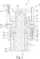
- Fig. 1shows a detailed view of a chair 1, which is in particular an office chair.
- the chair 1here has an embodiment of a seat support 3.
- the seat support 3has a base support part 5 which, in the exemplary embodiment shown here, is set up to connect the seat support 3 to an installation part 7.
- the base support part 5is connected to the installation part 7.
- the set-up part 7is designed in particular as a base frame, it having a gas spring 9 which is set up for height adjustment of the chair 1.
- the seat support 3has an inner cone part 11, which can be plugged onto an outer cone part 13 of the installation part 7, in particular the gas spring 9, in particular is plugged here in order to connect the seat support 3 to the installation part 7.
- the seat support 3also has a seat support part 15 which is set up to arrange a seat cushion (not shown here) on the seat support part 15.
- the seat support part 15is arranged between a first elastic element 17 and a second elastic element 19, in particular in the axial direction, that is to say in the vertical direction , hence in Figure 1 clamped in the vertical direction between the elastic elements 17, 19.
- the elastic elements 17, 19are preferably prestressed.
- the first elastic element 17is supported on the base support part 5 on the one hand and on the seat support part 15 on the other hand.
- the second elastic element 19is supported on a counter bearing 21 on the one hand and on the seat support part 15 on the other. Due to the arrangement between the two elastic elements 17, 19, the seat support part 15 is mounted such that it can be tilted relative to the base support part 5, in particular in all directions, that is to say in particular about both horizontal Cartesian axes of the chair 1.
- the seat support 3also has a locking mechanism 23 which can be displaced between a locked position and a release position and in Figure 1 is shown in its release position.
- the locking mechanism 23is set up to lock an elastic displacement of the seat support part 15 relative to the base support part 5 in the locked position and to release the elastic displacement of the seat support part 15 relative to the base support part 5 in the release position.
- the behavior of the chair 1can be adapted to the circumstances and / or needs of a user depending on the situation, in that the tiltability of the seat support part 15 relative to the base support part 5 is blocked or released as required.
- the counter bearing 21is preferably screwed onto the inner cone part 11 of the base support part 5, whereby a prestress of the elastic elements 17, 19 can be set by the selection of the torque with which the counter bearing 21 is screwed onto the base support part 5 and in particular the inner cone part 11 thereof.
- the counter bearing 21is preferably designed as a nut.
- the inner cone part 11preferably has an external thread which meshes with an internal thread of the counter bearing 21.
- At least one of the elastic elements 17, 19, preferably both elastic elements 17, 19,is / are designed as an elastomer (s).
- the locking mechanism 23is preferably discreetly displaceable either in the locking position or in the release position, in particular no intermediate positions being provided.
- the locking mechanism 23preferably has an axially, that is to say in the vertical direction, displaceable locking ring 25 which, in the locking position, preferably encompasses the first elastic element 17 in a ring shape, in particular concentrically.
- release position shownis preferably axially, ie in the vertical direction, spaced from the first elastic element 17.
- the locking ring 25In the locked position, the locking ring 25 preferably strikes the seat support part 15.
- the locking ring 25is preferably held on the base support part 5, in particular held displaceably.
- the seat support part 15has a support body 27, which is set up to arrange the seat cushion on the seat support part 15, in particular on the support body 27.
- the seat support part 15has a stop part 29, which here in particular as a stop plate with a circumferential , the first elastic element 17 is formed around a concentrically encompassing collar 31, the stop part 29 being arranged between the support body 27 and the first elastic element 17.
- the locking ring 25strikes the stop part 29 in the locking position.
- the stop part 29is preferably fastened to the support body 27, in particular screwed to the support body 27.
- the locking mechanism 23 on the locking ring 25has a guide groove 33 which extends at least in regions along a helical line section and into which a guide projection 35 which is arranged on the base support part 5 and which is guided in the guide groove 33 engages.
- a link guideis realized for the locking ring 25, which allows an axial displacement of the locking ring 25 along a double arrow P between the locking position and the release position when a user rotates the locking ring 25 relative to the base support part 5.
- Fig. 2shows a representation of a first embodiment of the locking ring 25 and thus at the same time a first embodiment of the locking mechanism 23 for the seat support 3 according to Figure 1 .
- the locking ring 25has at least one guide groove 33, here three guide grooves 33 which are arranged at the same axial height and are identical to one another and are arranged at equal angular intervals from one another along the circumference of the locking ring 25, that is to say offset by 120 ° to one another.
- Each guide groove 33 of the locking ring 25is one - in Figure 1 recognizable - guide projection 35 assigned to the base support part 5, the respective guide projection 35 engaging in the guide groove 33 assigned to it.
- each guide groove 33is assigned to one of the two functional positions, that is to say the blocking position on the one hand and the release position on the other.
- a first end 34is assigned to the blocking position and a second end 36 to the release position.
- the guide grooves 33preferably have a flattened groove outlet 38 at least at their first end 34 assigned to the blocking position.
- the second end 36which is assigned to the release position, is not assigned a flattened slot outlet here.
- the groove outlet 38preferably forms an angle with the horizontal of at least 1 ° to at most 10 °, preferably up to at most 7 °, preferably up to at most 5 °, preferably up to at most 4 °, preferably up to at most 3 °, preferably at least 1.5 ° up to at most 2.5 °, preferably 2 °.
- the groove outlet 38it is also possible for the groove outlet 38 to be designed as a horizontal groove outlet, parallel to the horizontal.
- the guide grooves 33preferably have an incline in their helical section-shaped regions, at which no self-locking of the guide projections 35 occurs in the guide grooves 33. In this way, it is sufficient for the user, for example, to turn the locking ring 25 to such an extent that it comes out of the flattened slot outlet 38 of the locking position, the locking ring 25 automatically coming into the release position due to gravity. This requires a particularly simple operability of the locking mechanism 23.
- the locking mechanism 23has a locking position holding device 47 which is assigned to the locking position and which is designed to hold the locking mechanism 23 in the locking position.
- the blocking position holding device 47is realized here in particular by the flattened groove outlet 38.
- the locking mechanism 23is in particular set up to be pushed into the release position by gravitation.
- Fig. 3shows a detailed view of the seat support 3 with a second embodiment of the locking mechanism 23 and a second embodiment of the locking ring 25.
- the locking mechanism 23can be automatically shifted into the locking position, in this case in particular pretensioned into the locking position - and in Figure 3 shown in the locked position. It has a release position holding device 49 which is assigned to the release position and is designed to hold the locking mechanism 23 in the release position.
- the locking mechanism 23has a pretensioning device 51, which is set up to urge the locking mechanism 23 into the locking position, here in particular to bias it into the locking position.
- the pretensioning device 51is formed here by a torsion spring 53, which is set up to pretension the locking mechanism 23 into the locking position.
- the torsion spring 53preferably engages on the one hand on the screw receptacle 37 and on the other hand on the locking ring 25 and is designed to introduce a torque into the locking ring 25 which urges it in the direction of the locking position, in particular urging it into the locking position.
- the release position holding device 49is preferably designed as a latching device.
- the release position holding device 49is designed here as a latching position 55 for the guide projection 35 in the guide groove 33.
- the guide groove 35has a locking projection 57 in the region of the second end 36, behind which the guide projection 35 can be locked in the release position. If the guide projection 35 is released manually from the latching position 55 by a user, in particular, the locking ring 25 is forced into the locking position by the torsion spring 53.
- the guide groove 33preferably has an at least slightly flattened groove outlet 38 in the region of its first end 34 in order to improve an inhibition of the locking ring 25 in the locking position and thus to relieve the torsion spring 53.
- the guide groove 33can end at the first end 34 without a groove outlet, in particular without changing its slope.
- Fig. 4shows a further representation of the second embodiment of the locking ring 25 according to Figure 3 .
- the locking position 55 and the locking projection 57 in the region of the second end 36 of the guide groove 33can be clearly seen.
- Fig. 5shows a detailed view of the seat support 3 according to Figure 1 with a third embodiment of the locking ring 25 and at the same time a third embodiment of the locking mechanism 23.
- the locking mechanism 23can be automatically shifted into the locking position.
- the locking mechanism 23has a spring device 52 which is set up around the To push locking mechanism 23 into the locked position.
- the spring device 52has a pressure piece 61.
- the pressure piece 61preferably has a housing body 63 which is designed as a grub screw and has an external thread and a pressure body 65 which is acted upon by a spring element which is arranged in the housing body 63 and is therefore not shown here, and in particular is preloaded radially outwards.
- the pressure piece 61is in particular screwed into the screw receptacle 37 here.
- the screw receptacle 37preferably has a push-through opening 67 through which the pressure piece 61 can be passed, in order then to screw it into the screw receptacle 37 on the opposite side from the radial inside.
- a drive meansfor example a screwdriver, can also engage in the pressure piece 61 through the push-through opening 67 in order to screw it to the screw receptacle 37.
- the pressure piece 61interacts with a force deflecting structure 69 formed on the locking ring 25 in order to urge the locking ring 25 into the locking position.
- the pressure piece 61engages in the force deflection structure 69, in particular with the pressure body 65.
- the force deflecting structure 69is here in particular designed as a groove 71 widening in the direction of the blocking position.
- Fig. 6shows a further detailed view of the seat support 3 according to Figure 5 .
- the widening groove 71leads to the fact that the radially outward force of the pressure piece 61 is deflected into a torque which forces the locking ring 25 into the locking position, in particular by the pressure body 65 becoming ever wider into the widening groove 71 engages in the direction of the locked position.
- the spring-loaded pressure body 65increasingly radially emerges from the housing body 63 and enters the widening groove 71.
- the locking mechanism 23also has a release position holding device 49 which is assigned to the release position and which is set up to hold the locking mechanism 23 in the release position.
- the release position holding device 49is here in particular designed as a latching point 73 for the pressure piece 61, in particular as a bore or recess 75, in which the pressure piece 61, in particular the pressure body 65, engages in the release position.
- the widening groove 71is spaced from the detent point 73 in the circumferential direction and in the axial direction, in particular along a displacement path or a displacement path of the pressure piece 61 on the locking ring 25 between the release position and the locking position.
- An undamaged area of the locking ring 25is arranged between the locking point 73 and the widening groove 71.
- This areain which the locking mechanism 23 can be displaced automatically, preferably comprises the last 2 to 3 mm - in the axial direction - of the tensioning path of the locking ring 25 between the release position and the locking position.
- the locking mechanism 23preferably has three pressure pieces 61 which are arranged in a uniformly distributed manner, in particular along the circumference of the screw receptacle 37. Accordingly, the locking ring 25 then preferably has three force deflection structures 69, in particular widening grooves 71. Three locking points 73 are preferably also provided accordingly.
- the force deflection structure 69 and the locking point 73are preferably arranged or formed offset on the locking ring 25 in the circumferential direction and / or in the axial direction to the guide groove 33.
- the inner cone part 11 and the screw receptacle 37can be formed in one piece with one another. In this case, lower overall heights can advantageously be realized for the seat support 3.
- an axial position of the locking ring 25 on the base support part 5is preferably adjustable in the release position.
- a bias of the locking ring 25 in the locking positioncan be set, which is caused by the first elastomer 17.
- the axial position of the guide projection 35can also be shifted, so that the position of the release position changes overall, and at the same time - via the constant axial stroke between the locking position and the release position - the axial position Position of the blocking position is shifted.
- the first elastomer 17must be stretched in the locking position the higher the locking ring 25 is arranged in the release position; the stop member 29 is thus more or less raised by the locking ring 25 against a restoring force of the first elastomer 17 in the locking position, thus the first elastomer 17 is stretched the higher the locking ring 25 is arranged in the release position.
- the base part 5preferably has a screw receptacle 37 on which the guide projection 35 is arranged and which, relative to a base body 39, the base support part 5 can be displaced in the axial direction - in particular by screws.
- the screw receptacle 37is screwed, in particular with an internal thread, onto an external thread of the base body 39.
- the pretensioncan thus be adjusted by screwing the screw receptacle 37 relative to the base body 39, thereby simultaneously adjusting the axial position of the guide projection 35.
- the screw receptacle 37is in Figure 1 shown in a highest possible position relative to the base body 39, thus in a position of maximum preload for the locking mechanism 23 in the locking position.
- the axial position of the screw receptacle 37 and thus at the same time the locking ring 25can be fixed in the release position by a counter plate 41, the counter plate 41 being able to be screwed in particular against the screw receptacle 37, preferably by screw elements which extend in the axial direction and which fit into corresponding screw holes of the Base support part 5 are screwed.
- the seat support 3also has a gripping element 43 which engages around the locking ring 25 and is operatively connected to the locking mechanism 23, here in particular to the locking ring 25, for actuating it.
- the gripping element 43is coupled to the locking ring 25 in a torque-transmitting manner. It preferably has a gripping structure, in particular a gripping surface, preferably with an increased roughness, or an arrangement of depressions and / or elevations on an outer surface, in particular an outer peripheral surface 45, so that the gripping element 45 can be gripped and operated securely and securely by a user is.
- the locking ring 25preferably has at least one engagement groove 59, here in particular three engagement grooves 59, two of which are visible, into which correspondingly formed projections of the gripping element 43 can engage in order to couple the gripping element 43 to the locking ring 25 in a torque-transmitting manner .
- the chair 1preferably has the seat cushion and a backrest in a manner not shown here; further preferably a synchronous mechanism by means of which the seat support part 15 can be pivoted synchronously with the backrest.
Landscapes
- Chairs Characterized By Structure (AREA)
Abstract
Translated fromGermanDescription
Translated fromGermanDie Erfindung betrifft einen Sitzträger für einen Stuhl sowie einen Stuhl mit einem solchen Sitzträger.The invention relates to a seat support for a chair and a chair with such a seat support.
Aus der deutschen Offenlegungsschrift
Zugleich zeigt sich, dass die Kippbewegungen des Sitztragteils relativ zu dem Grundtragteil einen permanenten Ausgleich, somit eine permanente Bewegung des Benutzers verlangen. Dies wird nicht von allen Nutzern oder nicht in jeder Situation geschätzt. Selbst wenn ein Nutzer in manchen Situationen die Kippbewegungen schätzen würde, wobei er jedoch in anderen Situationen keine solchen Kippbewegungen wünscht, wird er sich möglicherweise gegen einen Stuhl mit einem solchen Sitzträger entscheiden.At the same time, it can be seen that the tilting movements of the seat support part relative to the base support part require permanent compensation, and thus permanent movement of the user. This is not appreciated by all users or not in every situation. Even if a user would appreciate the tilting movements in some situations, but in other situations he does not want such tilting movements, he may decide against a chair with such a seat support.
Der Erfindung liegt daher die Aufgabe zugrunde, einen Sitzträger für einen Stuhl sowie einen Stuhl mit einem solchen Sitzträger zu schaffen, wobei die genannten Nachteile nicht auftreten.The invention is therefore based on the object of providing a seat support for a chair and a chair having such a seat support, the disadvantages mentioned not occurring.
Die Aufgabe wird gelöst, indem die vorliegende technische Lehre bereitgestellt wird, insbesondere die Lehre der unabhängigen Ansprüche sowie der in den abhängigen Ansprüchen und der Beschreibung offenbarten Ausführungsformen.The object is achieved by providing the present technical teaching, in particular the teaching of the independent claims and of the embodiments disclosed in the dependent claims and the description.
Die Aufgabe wird insbesondere gelöst, indem ein Sitzträger der zuvor angesprochenen Art einen Sperrmechanismus aufweist, der zwischen einer Sperrstellung und einer Freigabestellung verlagerbar und eingerichtet ist, um in der Sperrstellung eine elastische Verlagerung des Sitztragteils relativ zu dem Grundtragteil zu sperren, und in der Freigabestellung die elastische Verlagerung des Sitztragteils relativ zu dem Grundtragteil freizugeben. Auf diese Weise ist es möglich, Kippbewegungen zwischen dem Sitztragteil und dem Grundtragteil zuzulassen, wenn diese gewünscht sind, sie jedoch dann, wenn sie unerwünscht sind, entweder dauerhaft oder zeitweise, insbesondere situationsabhängig, zu unterbinden, indem der Sperrmechanismus entweder in der Sperrstellung oder in der Freigabestellung angeordnet wird. Somit können auch Nutzer, die nur phasenweise - oder gegebenenfalls sogar selten bis nie - eine elastische Kippbewegung zwischen dem Sitztragteil und dem Grundtragteil wünschen, sich für einen Stuhl entscheiden, der den hier vorgeschlagenen Sitzträger aufweist.The object is achieved in particular in that a seat support of the type mentioned above has a locking mechanism which can be displaced and set up between a locking position and a release position in order to lock an elastic displacement of the seat support part relative to the base support part in the locking position, and in the release position to release elastic displacement of the seat support part relative to the base support part. In this way, it is possible to allow tilting movements between the seat support part and the base support part if these are desired, but to prevent them either permanently or temporarily, especially depending on the situation, if they are undesirable, by the locking mechanism either in the locked position or in the release position is arranged. Thus, even users who only want an elastic tilting movement between the seat support part and the base support part only in phases - or possibly even rarely or never - can opt for a chair that has the seat support proposed here.
Das Grundtragteil ist eingerichtet, um den Sitzträger entweder aufzustellen, oder um den Sitzträger mit einem Aufstellteil zu verbinden. Insbesondere ist es möglich, dass das Grundtragteil selbst als Fußgestell eines Stuhls, insbesondere als Fußkreuz ausgebildet ist, vorzugsweise mit bevorzugt fünf Armen, an deren freien Enden Rollen oder Gleitelemente vorgesehen sind, und die im Bereich ihrer gegenüberliegenden gemeinsamen Enden gemeinsam ein Stützrohr halten, welches dann das Sitztragteil trägt. Dabei ist es möglich, dass das Grundtragteil eine Gasfeder, insbesondere zur Höhenverstellung des Stuhls, aufweist.The basic support part is set up to either set up the seat support or to connect the seat support to an installation part. In particular, it is possible that the base support part itself is designed as a foot frame of a chair, in particular as a star base, preferably with preferably five arms, on the free ends of which rollers or sliding elements are provided, and which together hold a support tube in the region of their opposite common ends, which then carries the seat support part. It is possible that the base support part has a gas spring, in particular for height adjustment of the chair.
Alternativ ist es möglich, dass das Grundtragteil eingerichtet ist, um mit einem insbesondere als Fußgestell, vorzugsweise als Fußkreuz ausgebildeten Aufstellteil verbunden zu werden. Auch in diesem Fall weist ein solches Fußkreuz vorzugsweise in der Regel fünf Arme auf, an deren freien Enden Rollen oder Gleitelemente vorgesehen sind, und die im Bereich ihrer gegenüberliegenden gemeinsamen Enden gemeinsam ein Stützrohr halten, welches dann das Grundtragteil trägt. Auch in diesem Fall ist es möglich, dass das Fußgestell eine Gasfeder zur Höhenverstellung des Stuhls aufweist, wobei dann das Grundtragteil vorzugsweise mit der Gasfeder mechanisch verbindbar oder verbunden ist.Alternatively, it is possible for the base support part to be set up to be connected to a set-up part which is designed in particular as a base frame, preferably as a base. In this case too, such a base preferably has five arms, on the free ends of which rollers or sliding elements are provided, and which together hold a support tube in the region of their opposite common ends, which then carries the basic supporting part. In this case too, it is possible for the base frame to have a gas spring for height adjustment of the chair, in which case the base support part is preferably mechanically connectable or connected to the gas spring.
Vorzugsweise weist das Grundtragteil eine Verbindungsgeometrie zur Verbindung mit dem Aufstellteil auf, insbesondere einen Innenkonus, der auf einen Außenkonus des Aufstellteils, besonders bevorzugt einen Außenkonus einer Gasfeder, aufgesteckt wird. Alternativ oder zusätzlich ist es möglich, dass das Grundtragteil mit dem Aufstellteil verschraubt oder in anderer geeigneter Weise an diesem befestigt wird.The base support part preferably has a connection geometry for connection to the set-up part, in particular an inner cone, which is plugged onto an outer cone of the set-up part, particularly preferably an outer cone of a gas spring. As an alternative or in addition, it is possible for the base support part to be screwed to the set-up part or to be fastened to it in another suitable manner.
Der Sitzträger ist insbesondere eingerichtet zu Verwendung in einem Bürostuhl. Hier ergeben sich in besonderer Weise die Vorteile des Sitzträgers, insbesondere aufgrund der hohen täglichen zeitlichen Nutzdauer eines solchen Bürostuhls durch seinen Nutzer.The seat support is especially designed for use in an office chair. The advantages of the seat support result in a special way here, in particular due to the high daily useful life of such an office chair by its user.
Das Sitztragteil ist vorzugsweise eingerichtet, um ein Sitzkissen mittelbar - vermittelt über wenigstens ein weiteres Teil - oder unmittelbar an dem Sitztragteil anzuordnen. Insbesondere kann das Sitzkissen an dem Sitztragteil befestigt werden, vorzugsweise durch Verschrauben. Hierzu weist das Sitztragteil vorzugsweise wenigstens eine Schraubbohrung, vorzugsweise eine Mehrzahl von Schraubbohrungen auf, um das Sitzkissen an dem Sitztragteil zu befestigen.The seat support part is preferably set up to arrange a seat cushion indirectly - mediated via at least one further part - or directly on the seat support part. In particular, the seat cushion can be attached to the seat support part, preferably by screwing. For this purpose, the seat support part preferably has at least one screw hole, preferably a plurality of screw holes, in order to fasten the seat cushion to the seat support part.
In bevorzugter Ausgestaltung ist das Sitztragteil eingerichtet, um eine Stuhlmechanik aufzunehmen, wobei die Stuhlmechanik insbesondere eine Synchronmechanik zur synchronen Verkippung einer Sitzlehne gemeinsam mit dem Sitztragteil um eine Horizontalachse aufweist, insbesondere um es einem Nutzer zu ermöglichen, sich mit dem Sitzkissen und der Sitzlehne nach hinten zurückzulehnen. Die Stuhlmechanik weist außerdem bevorzugt einen Mechanismus auf, um eine Vorspannung für diese Kippbewegung einzustellen. Weiterhin weist die Stuhlmechanik bevorzugt einen Mechanismus auf, der es erlaubt, diese Kippbewegung zu sperren.In a preferred embodiment, the seat support part is designed to accommodate a chair mechanism, the chair mechanism in particular having a synchronous mechanism for synchronously tilting a seat back together with the seat support part about a horizontal axis, in particular in order to enable a user to sit backwards with the seat cushion and the seat back to lean back. The chair mechanism also preferably has a mechanism for setting a pretension for this tilting movement. Furthermore, the chair mechanism preferably has a mechanism that allows this tilting movement to be blocked.
Gemäß einer bevorzugten Ausgestaltung ist das Sitztragteil aus Druckguss, insbesondere Aluminiumdruckguss, gefertigt. Es ist aber auch möglich, dass das Sitztragteil aus einem Kunststoff oder einem anderen geeigneten Material gefertigt ist. Es weist bevorzugt wenigstens einen Hohlraum sowie Bohrungen zur Aufnahme der Stuhlmechanik auf.According to a preferred embodiment, the seat support part is made of die-cast, in particular aluminum die-cast. But it is also possible that the seat support part is made of a plastic or another suitable material. It preferably has at least one cavity and bores for receiving the chair mechanism.
Das Sitztragteil ist insbesondere in Hochrichtung - das heißt in axialer Richtung - des Sitzträgers gesehen zwischen dem ersten elastischen Element und dem zweiten elastischen Element angeordnet, insbesondere zwischen dem ersten elastischen Element und dem zweiten elastischen Element eingespannt. Dabei entspricht eine Hochrichtung einer Richtung, die bei bestimmungsgemäßer Orientierung des Sitzträgers vertikal ausgerichtet ist, wobei die Hochrichtung bevorzugt zugleich die Hochrichtung eines Stuhls ist, der den Sitzträger aufweist.The seat support part is arranged in particular in the vertical direction - that is to say in the axial direction - of the seat support between the first elastic element and the second elastic element, in particular clamped between the first elastic element and the second elastic element. A vertical direction corresponds to a direction that at intended orientation of the seat support is oriented vertically, the vertical direction preferably being the vertical direction of a chair which has the seat carrier.
Wenigstens ein elastisches Element, ausgewählt aus dem ersten elastischen Element und dem zweiten elastischen Element ist bevorzugt vorgespannt. Vorzugsweise sind beide elastischen Elemente vorgespannt, um die gegen die elastische Kippbewegung des Sitztragteils relativ zu dem Grundtragteil wirkenden Rückstellkräfte einzustellen.At least one elastic element selected from the first elastic element and the second elastic element is preferably prestressed. Both elastic elements are preferably prestressed in order to adjust the restoring forces acting against the elastic tilting movement of the seat support part relative to the base support part.
Das erste elastische Element stützt sich bevorzugt einseitig, insbesondere an seiner Unterseite, an dem Grundtragteil, und auf seiner anderen, in Hochrichtung gegenüberliegenden Seite, insbesondere seiner Oberseite, an dem Sitztragteil ab. Das zweite elastische Element stützt sich bevorzugt an seiner einen Seite, insbesondere Oberseite, an dem Gegenlager, und auf seiner anderen, gegenüberliegenden Seite, insbesondere Unterseite, an dem Sitztragteil ab.The first elastic element is preferably supported on one side, in particular on its underside, on the base support part, and on its other, opposite side in the vertical direction, in particular its top side, on the seat support part. The second elastic element is preferably supported on one side, in particular the upper side, on the counter bearing and on its other, opposite side, in particular the lower side, on the seat support part.
Das Gegenlager ist vorzugsweise auf das Grundtragteil aufgebracht, insbesondere an dem Grundtragteil befestigt, bevorzugt auf das Grundtragteil aufgeschraubt, wobei insbesondere durch Einstellen des Drehmoments beim Aufschrauben des Gegenlagers auf das Grundtragteil die Vorspannung zumindest des zweiten elastischen Elements, vorzugsweise beider elastischen Elemente, eingestellt werden kann. Besonders bevorzugt ist das Gegenlager auf den Innenkonus aufgeschraubt, mit dem der Sitzträger auf das Aufstellteil aufgesetzt werden kann. Hierzu weist der Innenkonus bevorzugt ein Außengewinde auf, das mit einem Innengewinde des Gegenlagers kämmt. Das Gegenlager ist in bevorzugter Ausgestaltung als Mutter ausgebildet.The counter bearing is preferably applied to the base support part, in particular fastened to the base support part, preferably screwed onto the base support part, the pretensioning of at least the second elastic element, preferably both elastic elements, being able to be adjusted in particular by adjusting the torque when the counter support is screwed onto the base support part . The counter bearing is particularly preferably screwed onto the inner cone, with which the seat support can be placed on the installation part. For this purpose, the inner cone preferably has an external thread that meshes with an internal thread of the counter bearing. In a preferred embodiment, the counter bearing is designed as a nut.
Der Sperrmechanismus ist vorzugsweise eingerichtet, um wenigstens ein elastisches Element, ausgewählt aus dem ersten elastischen Element und dem zweiten elastischen Element, zu sperren, das heißt an einer elastischen Deformation, insbesondere Biegung, zu hindern. Vorzugsweise sperrt der Sperrmechanismus zugleich das erste elastische Element und das zweite elastische Element.The locking mechanism is preferably set up to lock at least one elastic element, selected from the first elastic element and the second elastic element, that is to prevent elastic deformation, in particular bending. The locking mechanism preferably locks the first elastic element and the second elastic element at the same time.
Zumindest ein elastisches Element, ausgewählt aus dem ersten elastischen Element und dem zweiten elastischen Element, ist bevorzugt als Elastomer ausgebildet oder aus einem Elastomer gebildet. Besonders bevorzugt sind beide elastischen Elemente als Elastomere ausgebildet, oder aus einem Elastomer, oder aus verschiedenen Elastomeren, gebildet. Auf diese Weise können die elastischen Elemente zugleich einfach, raumsparend und kostengünstig bereitgestellt werden.At least one elastic element, selected from the first elastic element and the second elastic element, is preferably designed as an elastomer or formed from an elastomer. Both elastic elements are particularly preferably designed as elastomers, or formed from one elastomer, or from different elastomers. In this way, the elastic elements can be provided in a simple, space-saving and inexpensive manner.
Gemäß einer Weiterbildung der Erfindung ist vorgesehen, dass der Sperrmechanismus ausschließlich in die Sperrstellung oder in die Freigabestellung verlagerbar ist. Der Sperrmechanismus weist also genau zwei diskrete Zustände auf, zwischen denen er verlagert werden kann, jedoch keine Zwischenstellungen zwischen der Sperrstellung und der Freigabestellung. Auf diese Weise ist der Sperrmechanismus besonders einfach und intuitiv bedienbar, und es ist ein schnelles Umschalten zwischen der Sperrstellung und der Freigabestellung möglich.According to a development of the invention, it is provided that the locking mechanism can only be displaced into the locking position or into the release position. The locking mechanism thus has exactly two discrete states between which it can be shifted, but no intermediate positions between the locking position and the release position. In this way, the locking mechanism is particularly simple and intuitive to use, and it is possible to quickly switch between the locking position and the release position.
Gemäß einer Weiterbildung der Erfindung ist vorgesehen, dass der Sperrmechanismus einen axial - das heißt in Hochrichtung - verlagerbaren Sperrring aufweist, der vorzugsweise in der Sperrstellung das erste elastische Element ringförmig, insbesondere konzentrisch, umgreift, wobei er vorzugsweise in der Freigabestellung - in Hochrichtung - beabstandet von dem ersten elastischen Element angeordnet ist. Auf diese Weise kann das erste elastische Element sehr einfach, stabil und sicher durch den Sperrmechanismus gesperrt werden.According to a development of the invention, it is provided that the locking mechanism has an axially displaceable locking ring, that is to say in the vertical direction, which preferably surrounds the first elastic element in a ring-shaped manner, in particular concentrically, in the locking position, preferably spaced apart in the release position - in the vertical direction is arranged by the first elastic element. In this way, the first elastic element can be locked very easily, stably and securely by the locking mechanism.
Gemäß einer Weiterbildung der Erfindung ist vorgesehen, dass der Sperrmechanismus, vorzugsweise der Sperrring, in der Sperrstellung an dem Sitztragteil anschlägt. Auf diese Weise kann der Sperrmechanismus, insbesondere der Sperrring, in einfacher und stabiler Weise eine Bewegung des Sitztragteils in der Sperrstellung verhindern. Besonders bevorzugt schlägt der Sperrmechanismus, insbesondere der Sperrring, dabei an dem beweglichen Element des Sitzträgers an und hält dieses in einer fixierten Position, sodass die Beweglichkeit unterbunden ist.According to a development of the invention, it is provided that the locking mechanism, preferably the locking ring, strikes the seat support part in the locked position. In this way, the locking mechanism, in particular the locking ring, can prevent movement of the seat support part in the locked position in a simple and stable manner. The locking mechanism, in particular the locking ring, particularly preferably strikes the movable element of the seat carrier and holds it in a fixed position, so that mobility is prevented.
In der Freigabestellung ist der Sperrmechanismus, insbesondere der Sperrring, bevorzugt von dem Sitztragteil beabstandet, sodass dieses frei verkippt werden kann.In the release position, the locking mechanism, in particular the locking ring, is preferably spaced from the seat support part so that it can be tilted freely.
Gemäß einer Weiterbildung der Erfindung ist vorgesehen, dass der Sperrmechanismus, vorzugsweise der Sperrring, an dem Grundtragteil gehalten ist. Auf diese Weise ist der Sperrmechanismus, insbesondere der Sperrring, bevorzugt an dem feststehenden Teil des Sitzträgers angeordnet, sodass in sehr stabiler Weise Kräfte in der Sperrstellung in das Grundtragteil als feststehendes Teil eingeleitet und dort aufgenommen werden. Insbesondere ist der Sperrmechanismus, vorzugsweise der Sperrring, axial verlagerbar, das heißt in Hochrichtung verlagerbar, an dem Grundtragteil gehalten. Somit kann er axial zwischen der Freigabestellung und der Sperrstellung verlagert werden. Insbesondere kann so in einfacher Weise ein Anschlag des Sperrrings in der Sperrstellung an dem Sitztragteil bewirkt werden, wobei der Sperrring in der Freigabestellung von dem Sitztragteil beabstandet ist.According to a development of the invention, it is provided that the locking mechanism, preferably the locking ring, is held on the base support part. In this way, the locking mechanism, in particular the locking ring, is preferably arranged on the fixed part of the seat support, so that forces in the locked position are introduced into the base support part as a fixed part and are absorbed there. In particular, the locking mechanism, preferably the locking ring, is axially displaceable, that is to say displaceable in the vertical direction, held on the base support part. It can thus be axially displaced between the release position and the blocking position. In particular, a stop can be done in a simple manner of the locking ring in the locking position on the seat support part, the locking ring being spaced from the seat support part in the release position.
Besonders bevorzugt ist der Sperrring an dem Grundtragteil axial verlagerbar gehalten und schlägt in der Sperrstellung an dem Sitztragteil an, wobei er in der Freigabestellung von dem Sitztragteil beabstandet ist. Zugleich umgreift der Sperrring bevorzugt in der Sperrstellung das erste elastische Element ringförmig, insbesondere konzentrisch, wobei er in der Freigabestellung axial von dem ersten elastischen Element beabstandet angeordnet ist.The locking ring on the base support part is particularly preferably held so as to be axially displaceable and abuts the seat support part in the locked position, being spaced apart from the seat support part in the release position. At the same time, the locking ring preferably surrounds the first elastic element in a ring-shaped manner, in particular concentrically, in the locking position, wherein it is arranged axially spaced from the first elastic element in the release position.
Gemäß einer Weiterbildung der Erfindung ist vorgesehen, dass das Sitztragteil einen Tragkörper aufweist, der eingerichtet ist zur Anordnung eines Sitzkissens an dem Tragkörper, wobei das Sitztragteil außerdem ein Anschlagteil aufweist, wobei das Anschlagteil - in Hochrichtung gesehen - unter dem Tragkörper angeordnet, insbesondere befestigt, vorzugsweise angeschraubt, ist. Dabei schlägt der Sperrmechanismus, insbesondere der Sperrring, in der Sperrstellung bevorzugt an dem Anschlagteil an. In vorteilhafter Weise wird so ein separates, mit dem Tragkörper verbundenes Teil bereitgestellt, an welches der Sperrmechanismus in der Sperrstellung anschlägt, und welches an die in dieser Stellung herrschenden Kräfte angepasst sein kann. Das Anschlagteil ist in bevorzugter Ausgestaltung als Anschlagplatte ausgebildet.According to a development of the invention, it is provided that the seat support part has a support body which is set up to arrange a seat cushion on the support body, the seat support part also having a stop part, the stop part - viewed in the vertical direction - arranged under the support body, in particular fastened, preferably screwed. The locking mechanism, in particular the locking ring, preferably strikes the stop part in the locking position. This advantageously provides a separate part connected to the support body, to which the locking mechanism strikes in the locking position and which can be adapted to the forces prevailing in this position. In a preferred embodiment, the stop part is designed as a stop plate.
Das Anschlagteil, insbesondere die Anschlagplatte, ist bevorzugt zwischen dem Tragkörper und dem ersten elastischen Element angeordnet, wobei das Anschlagteil in radialer Richtung, das heißt senkrecht zur Hochrichtung, insbesondere allseitig über das erste elastische Element hinaus ragt. Besonders bevorzugt umgreift das Anschlagteil das erste elastische Element in Umfangsrichtung gesehen mit einem in vertikaler Richtung - nach unten - umgebogenen, in Umfangsrichtung umlaufenden Rand. Besonders bevorzugt ist das Anschlagteil ringförmig, insbesondere kreisringförmig, ausgebildet.The stop part, in particular the stop plate, is preferably arranged between the support body and the first elastic element, the stop part projecting beyond the first elastic element in all directions in the radial direction, that is to say perpendicular to the vertical direction. Particularly preferably, the stop part encompasses the first elastic element, seen in the circumferential direction, with an edge that is bent over in the vertical direction — downward — and encircles in the circumferential direction. The stop part is particularly preferably annular, in particular circular.
Gemäß einer Weiterbildung der Erfindung ist vorgesehen, dass der Sperrmechanismus an einem ersten Teil, das ausgewählt ist aus dem Sperrring und dem Grundtragteil, eine zumindest bereichsweise entlang eines Schraubenlinienabschnitts verlaufende Führungsnut, und an einem zweiten Teil, das ausgewählt ist aus dem Grundtragteil und dem Sperrring, einen Führungsvorsprung aufweist, wobei der Führungsvorsprung in die Führungsnut eingreift und in der Führungsnut geführt ist. Das erste Teil und das zweite Teil sind dabei verschieden voneinander. Insbesondere ist das erste Teil der Sperrring, wenn das zweite Teil das Grundtragteil ist, und umgekehrt. Mittels der Führungsnut, in welche der Führungsvorsprung eingreift, wird eine Kulissenführung für den Sperrmechanismus bereitgestellt, wobei der Sperrring in axialer Richtung, also in Hochrichtung, zwangsgeführt wird, wenn er in Umfangsrichtung gedreht wird, da in diesem Fall der Führungsvorsprung entlang der schraublinienabschnittsförmigen Führungsnut gleitet, und so der Sperrring zwangsläufig im Wege seiner Verlagerung in Umfangsrichtung auch eine Verlagerung in axialer Richtung, das heißt in Hochrichtung, mithin einen Hub, erfährt. Der Sperrmechanismus ist so sehr einfach zu bedienen.According to a development of the invention, it is provided that the locking mechanism on a first part, which is selected from the locking ring and the base support part, has a guide groove running at least in regions along a helical line section, and on a second part, which is selected from the base support part and the locking ring , has a guide projection, the guide projection engaging in the guide groove and being guided in the guide groove. The first part and the second part are different from each other. In particular, the first part is the locking ring when the second part is the basic supporting part, and vice versa. By means of the guide groove in which the guide projection engages, a link guide is provided for the locking mechanism, the locking ring being positively guided in the axial direction, i.e. in the vertical direction, when it is rotated in the circumferential direction, since in this case the guide projection slides along the guide groove in the form of a screw portion, and thus the locking ring inevitably gets in the way its shift in the circumferential direction also undergoes a shift in the axial direction, that is to say in the vertical direction, and consequently a stroke. The locking mechanism is very easy to use.
In bevorzugter Ausgestaltung ist das erste Teil der Sperrring, und das zweite Teil ist das Grundtragteil, sodass die Führungsnut an dem Sperrring ausgebildet, und der Führungsvorsprung an dem Grundtragteil angeordnet ist.In a preferred embodiment, the first part is the locking ring, and the second part is the base support part, so that the guide groove is formed on the lock ring and the guide projection is arranged on the base support part.
Vorzugsweise ist jeweils ein Ende der beiden Enden der Führungsnut je einer der Funktionsstellungen zugeordnet, sodass eine Relativverlagerung zwischen dem Führungsvorsprung und der Führungsnut stets vollständig, bis zum jeweiligen Ende der Führungsnut erfolgen kann, um die jeweilige Funktionsstellung zu erreichen. Somit sind die beiden Funktionsstellungen genau definiert.Preferably, one end of each of the two ends of the guide groove is assigned to one of the functional positions, so that a relative displacement between the guide projection and the guide groove can always take place completely up to the respective end of the guide groove in order to achieve the respective functional position. The two functional positions are thus precisely defined.
Vorzugsweise erstreckt sich die schraubenlinienabschnittsförmige Führungsnut in Umfangsrichtung - insbesondere in Projektion auf eine horizontale Ebene entlang einer Umfangslinie gesehen - entlang eines Winkelbereichs von mindestens 40° bis höchstens 100°, vorzugsweise von mindestens 50° bis höchstens 90°, vorzugsweise von mindestens 60° bis höchstens 90°, vorzugsweise von mindestens 70° bis höchstens 85°, vorzugsweise von mindestens 75° bis höchstens 85°, vorzugsweise von 80°.The helical section-shaped guide groove preferably extends in the circumferential direction - in particular when viewed on a horizontal plane along a circumferential line - along an angular range of at least 40 ° to at most 100 °, preferably from at least 50 ° to at most 90 °, preferably from at least 60 ° to at most 90 °, preferably from at least 70 ° to at most 85 °, preferably from at least 75 ° to at most 85 °, preferably from 80 °.
Eine horizontale Ebene ist insbesondere eine Ebene, auf der die Hochrichtung senkrecht steht. Eine Horizontale ist entsprechend insbesondere eine Achse in einer horizontalen Ebene, die mit der Hochrichtung einen rechten Winkel einschließt.A horizontal plane is in particular a plane on which the vertical direction is perpendicular. A horizontal line is accordingly, in particular, an axis in a horizontal plane, which includes a right angle with the vertical direction.
Vorzugsweise weist das erste Teil zwei Führungsnuten oder drei Führungsnuten, und bevorzugt das zweite Teil entsprechend zwei Führungsvorsprünge oder drei Führungsvorsprünge auf, wobei vorzugsweise jeder Führungsnut jeweils ein Führungsvorsprung zugeordnet ist, der in die jeweilige Führungsnut eingreift. Vorzugsweise sind die Führungsvorsprünge in Umfangsrichtung gesehen um 180° - bei zwei Führungsvorsprüngen - oder um 120° - bei drei Führungsvorsprüngen - zueinander versetzt und besonders bevorzugt in gleicher axialer Höhenlage zueinander angeordnet. Die Führungsnuten sind bevorzugt diametral einander gegenüberliegend oder um 120° zueinander versetzt angeordnet, wobei sie vorzugsweise, insbesondere bezogen auf äquivalente Punkte der Führungsnuten, auf einer gleichen Höhenlage miteinander angeordnet sind. Insbesondere sind die Enden der Führungsnuten jeweils auf gleichen Höhenlagen miteinander angeordnet.The first part preferably has two guide grooves or three guide grooves, and preferably the second part has two guide projections or three guide projections, each guide groove preferably being assigned a guide projection which engages in the respective guide groove. The guide projections are preferably offset from one another in the circumferential direction by 180 ° - in the case of two guide projections - or by 120 ° - in the case of three guide projections - and particularly preferably in the same axial direction Altitude arranged to each other. The guide grooves are preferably arranged diametrically opposite one another or offset by 120 ° to one another, wherein they are preferably arranged at the same height with one another, in particular in relation to equivalent points of the guide grooves. In particular, the ends of the guide grooves are each arranged at the same height.
Gemäß einer Weiterbildung der Erfindung ist vorgesehen, dass die Führungsnut zumindest an ihrem der Sperrstellung zugewandten Ende einen abgeflachten Nutauslauf aufweist. Dabei bedeutet "abgeflacht", dass die Führungsnut im Bereich des Nutauslaufs eine geringere Steigung aufweist als außerhalb des Nutauslaufs, wobei die Führungsnut im Bereich des Nutauslaufs insbesondere mit einer Horizontalen einen kleineren Winkel einschließt als außerhalb des Nutauslaufs. Auf diese Weise kann der Sperrring einfach, sicher und stabil in der Sperrstellung gehalten werden, indem der Führungsvorsprung in dem abgeflachten Nutauslauf angeordnet wird, wobei keine oder nur eine geringe Kraft - insbesondere geringer als die Haftreibung in dem Nutauslauf - in der Sperrstellung wirkt, die den Sperrring in die Freigabestellung drängt.According to a development of the invention, it is provided that the guide groove has a flattened groove outlet at least at its end facing the blocking position. "Flattened" means that the guide groove in the area of the groove outlet has a smaller slope than outside the groove outlet, the guide groove in the area of the groove outlet enclosing a smaller angle, in particular with a horizontal, than outside the groove outlet. In this way, the locking ring can be held simply, securely and stably in the locking position by arranging the guide projection in the flattened slot outlet, with no or only a small force - in particular less than the static friction in the slot outlet - acting in the locking position, which pushes the locking ring into the release position.
Der Nutauslauf schließt mit der Horizontalen bevorzugt einen Winkel von mindestens 1° bis höchstens 10°, vorzugsweise bis höchstens 7°, vorzugsweise bis höchstens 5°, vorzugsweise bis höchstens 4°, vorzugsweise bis höchstens 3°, vorzugsweise von mindestens 1,5° bis höchstens 2,5°, vorzugsweise 2° ein. Es ist aber auch möglich, dass der Nutauslauf als horizontaler Nutauslauf, parallel zu der Horizontalen, ausgebildet ist.The groove outlet closes with the horizontal preferably an angle of at least 1 ° to at most 10 °, preferably up to at most 7 °, preferably up to at most 5 °, preferably up to at most 4 °, preferably up to at most 3 °, preferably from at least 1.5 ° to at most 2.5 °, preferably 2 °. However, it is also possible for the slot outlet to be designed as a horizontal slot outlet, parallel to the horizontal.
Es ist möglich, dass die Führungsnut auch an ihrem der Freigabestellung zugewandten Ende einen abgeflachten Nutauslauf aufweist. Alternativ kann dort insbesondere eine Rastposition ausgebildet sein, oder die Führungsnut endet ohne einen Nutauslauf, das heißt insbesondere ohne Änderung ihrer Steigung.It is possible that the guide groove also has a flattened groove outlet at its end facing the release position. Alternatively, a detent position can be formed there in particular, or the guide groove ends without a groove outlet, that is to say in particular without changing its slope.
Gemäß einer Weiterbildung der Erfindung ist vorgesehen, dass die Führungsnut in ihrem schraubenlinienabschnittsförmigen Bereich eine Steigung aufweist, bei der keine Selbsthemmung des Führungsvorsprungs in der Führungsnut auftritt. Somit ergibt sich eine besonders leichte, reibungsarme Verlagerung des Sperrrings in dem schraubenlinienabschnittsförmigen Bereich zwischen der Sperrstellung und der Freigabestellung.According to a development of the invention, it is provided that the guide groove has an incline in its helical section-shaped area, at which no self-locking of the guide projection occurs in the guide groove. This results in a particularly easy, low-friction displacement of the locking ring in the helical portion-shaped area between the locking position and the release position.
Unter einer Selbsthemmung ist hier eine gemäß der Erfindung bevorzugt vermiedene Ausgestaltung des schraubenlinienabschnittsförmigen Bereichs der Führungsnut mit einer Steigung zu verstehen, bei welcher die Haftreibung zwischen dem Führungsvorsprung und der Führungsnut stets größer wäre als eine entlang der Steigung wirkende Kraft, beispielsweise Hangabtriebskraft, sodass insbesondere keine selbsttätige Verlagerung des Sperrrings möglich wäre. Erfindungsgemäß bevorzugt ist allerdings in diesem Bereich keine Selbsthemmung vorgesehen, was bedeutet, dass die Steigung des schraubenlinienabschnittsförmigen Bereichs so gewählt ist, dass insbesondere eine gravitationsbedingt in die Freigabestellung drängende Kraft in der Führungsnut stets größer ist als die Haftreibung zwischen dem Führungsvorsprung und der Führungsnut.A self-locking feature here is a configuration of the guide groove-shaped region of the guide groove, preferably avoided, according to the invention, with a To understand slope, in which the static friction between the guide projection and the guide groove would always be greater than a force acting along the slope, for example downhill force, so that in particular no automatic displacement of the locking ring would be possible. According to the invention, however, no self-locking is preferably provided in this area, which means that the slope of the area in the form of a helical section is selected such that, in particular, a force in the guide groove that forces into the release position is always greater than the static friction between the guide projection and the guide groove.
Die Führungsnut schließt - außerhalb des Nutauslaufs - bevorzugt einen Winkel mit der Horizontalen von mindestens 11° bis höchstens 20°, vorzugsweise von mindestens 12° bis höchstens 19°, vorzugsweise von mindestens 13° bis höchstens 18°, vorzugsweise von höchstens 17°, vorzugsweise von mindestens 14° bis höchstens 16°, vorzugsweise 15°, ein.The guide groove closes - outside the groove outlet - preferably an angle with the horizontal of at least 11 ° to at most 20 °, preferably from at least 12 ° to at most 19 °, preferably from at least 13 ° to at most 18 °, preferably from at most 17 °, preferably from at least 14 ° to at most 16 °, preferably 15 °.
Gemäß einer Weiterbildung der Erfindung ist vorgesehen, dass eine axiale Position des Sperrrings an dem Grundtragteil in der Freigabestellung einstellbar ist. Hierzu sind vorzugsweise der Sperrmechanismus insgesamt, insbesondere der Führungsvorsprung und die Führungsnut, gemeinsam in axialer Richtung verlagerbar, sodass der Hub des Sperrrings nicht verändert wird, wenn seine axiale Position in der Freigabestellung verändert wird. Somit wird durch die Wahl der axialen Position des Sperrrings in der Freigabestellung zugleich dessen Relativposition zu dem ersten elastischen Element in der Sperrstellung bestimmt, wodurch eine Vorspannung des ersten elastischen Elements in der Sperrstellung einstellbar ist. Gegebenenfalls ist hierdurch zugleich eine Kraft einstellbar, die zum Verlagern des Sperrrings in die Sperrstellung erforderlich ist, insbesondere zum Verlagern des Führungsvorsprungs in den abgeflachten Nutauslauf, der der Sperrstellung zugeordnet ist. Der Sperrring dehnt das erste elastische Element insbesondere umso stärker in der Sperrstellung, je höher er - in Hochrichtung gesehen - in der Freigabestellung angeordnet ist, indem er in der Sperrstellung das Sitztragteil, insbesondere das Anschlagteil, von einem Grundkörper des Grundtragteils weg nach oben drängt.According to a development of the invention, it is provided that an axial position of the locking ring on the base support part can be adjusted in the release position. For this purpose, the locking mechanism as a whole, in particular the guide projection and the guide groove, can preferably be displaced together in the axial direction, so that the stroke of the locking ring is not changed when its axial position is changed in the release position. Thus, by the choice of the axial position of the locking ring in the release position, its relative position to the first elastic element in the locking position is determined at the same time, whereby a preload of the first elastic element can be set in the locking position. If necessary, a force that is necessary for moving the locking ring into the locking position, in particular for moving the guide projection into the flattened groove outlet, which is assigned to the locking position, can thereby be set at the same time. The locking ring stretches the first elastic element in particular in the locking position, the higher it is arranged in the release position - seen in the vertical direction - by pushing the seat support part, in particular the stop part, away from a base body of the base support part in the locking position.
Vorzugsweise weist das Grundtragteil den Grundkörper und eine Schraubaufnahme auf, wobei der Sperrring an der Schraubaufnahme gehalten ist. Die Schraubaufnahme ist vorzugsweise relativ zu dem Grundkörper des Grundtragteils in Hochrichtung verlagerbar, insbesondere durch Schrauben. Insbesondere weist die Schraubaufnahme ein Innengewinde auf, das mit einem Außengewinde des Grundkörpers kämmt. Durch Drehen der Schraubaufnahme relativ zu dem Grundkörper ist somit eine axiale Position der Schraubaufnahme und damit zugleich die axiale Position des Sperrrings einstellbar.The base support part preferably has the base body and a screw receptacle, the locking ring being held on the screw receptacle. The screw receptacle can preferably be displaced in the vertical direction relative to the base body of the base support part, in particular by screwing. In particular, the screw receptacle has an internal thread that meshes with an external thread of the base body. By turning the screw mount relative to that The base body is thus an axial position of the screw receptacle and thus at the same time the axial position of the locking ring adjustable.
Vorzugsweise weist das Grundtragteil eine Konterplatte auf, mittels derer die Schraubaufnahme in ihrer axialen Position fixiert werden kann. Die Konterplatte kann dabei mit dem selben Außengewinde des Grundkörpers kämmen wie die Schraubaufnahme. Alternativ oder zusätzlich kann die Konterplatte mit Befestigungsschrauben, insbesondere axial ausgerichteten Befestigungsschrauben, an dem Grundkörper fixierbar sein.The base support part preferably has a counter plate, by means of which the screw receptacle can be fixed in its axial position. The counter plate can mesh with the same external thread of the base body as the screw holder. Alternatively or additionally, the counter plate can be fixed to the base body with fastening screws, in particular axially aligned fastening screws.
Es bedarf somit eines Lösens der Konterplatte, um die axiale Position der Schraubaufnahme zu verändern.It is therefore necessary to loosen the counter plate in order to change the axial position of the screw receptacle.
Gemäß einer Weiterbildung der Erfindung ist vorgesehen, dass der Sitzträger ein Greifelement aufweist, das mit dem Sperrmechanismus zu dessen Betätigung wirkverbunden ist. Dieses Greifelement ermöglicht es einem Nutzer, den Sperrmechanismus in besonders einfacher und komfortabler Weise zu bedienen. Vorzugsweise umgreift das Greifelement den Sperrring in Umfangsrichtung gesehen. Mittels des Greifelements kann ein Nutzer insbesondere den Sperrmechanismus aus der Sperrstellung und/oder aus der Freigabestellung lösen, und/oder den Sperrmechanismus zwischen der Sperrstellung und der Freigabestellung verlagern.According to a development of the invention, it is provided that the seat support has a gripping element which is operatively connected to the locking mechanism for actuating it. This gripping element enables a user to operate the locking mechanism in a particularly simple and comfortable manner. The gripping element preferably encompasses the locking ring as seen in the circumferential direction. By means of the gripping element, a user can in particular release the locking mechanism from the locking position and / or from the release position, and / or shift the locking mechanism between the locking position and the release position.
Insbesondere ist das Greifelement mit dem Sperrring drehmomentübertragend gekoppelt, sodass ein durch den Nutzer in das Greifelement eingeleitetes Drehmoment durch das Greifelement auf den Sperrring übertragen wird. Dies kann in besonders bevorzugter Weise durch geeignete Paarung von wenigstens einem Vorsprung und wenigstens einer Aussparung einerseits an dem Greifelement und andererseits an dem Sperrmechanismus, insbesondere dem Sperrring, bewirkt werden.In particular, the gripping element is coupled to the locking ring in a torque-transmitting manner, so that a torque introduced by the user into the gripping element is transmitted through the gripping element to the locking ring. This can be achieved in a particularly preferred manner by suitable pairing of at least one projection and at least one recess on the one hand on the gripping element and on the other hand on the locking mechanism, in particular the locking ring.
Vorzugsweise weist das Greifelement an einer Außenfläche, insbesondere einer äußeren Umfangsfläche, eine Greifstruktur auf. An der Greifstruktur kann ein Nutzer besonders einfach und komfortabel sowie sicher und stabil angreifen. Die Greifstruktur umfasst bevorzugt eine griffige Oberfläche, insbesondere eine aufgeraute Oberfläche oder eine Oberfläche mit Erhebungen und/oder Vertiefungen, welche ein besonders sicheres, insbesondere rutschfestes und stabiles Greifen des Greifelements ermöglichen.The gripping element preferably has a gripping structure on an outer surface, in particular an outer peripheral surface. A user can grip the gripping structure particularly easily and comfortably as well as securely and stably. The gripping structure preferably comprises a grippy surface, in particular a roughened surface or a surface with elevations and / or depressions, which enable a particularly secure, in particular non-slip and stable gripping of the gripping element.
Das Greifelement ist vorzugsweise aus Kunststoff gebildet. Bevorzugt verdeckt das Greifelement den Sperrmechanismus und ist vorzugsweise optisch ansprechend gestaltet. Der Sitzträger gestaltet sich für den Nutzer in diesem Fall besonders formschön und ästhetisch.The gripping element is preferably made of plastic. The gripping element preferably covers the locking mechanism and is preferably designed to be visually appealing. In this case, the seat support is particularly elegant and aesthetic for the user.
Gemäß einer Weiterbildung der Erfindung ist vorgesehen, dass der Sperrmechanismus eine der Sperrstellung zugeordnete Sperrstellungs-Halteeinrichtung aufweist, die eingerichtet ist, um den Sperrmechanismus in der Sperrstellung zu halten. Der Sperrmechanismus kann bei dieser Ausgestaltung besonders einfach aufgebaut sein, wobei er insbesondere manuell von der Freigabestellung in die Sperrstellung verlagert werden kann, wobei er dort - gegen die in die Freigabestellung drängende Vorspannkraft der elastischen Elemente, insbesondere des ersten elastischen Elements, und/oder gegen die in die Freigabestellung drängende Schwerkraft, sicher durch die Sperrstellungs-Halteeinrichtung gehalten wird.According to a development of the invention, it is provided that the locking mechanism has a locking position holding device which is assigned to the locking position and which is set up to hold the locking mechanism in the locking position. In this embodiment, the locking mechanism can be constructed in a particularly simple manner, wherein it can in particular be shifted manually from the release position into the locking position, where it - against the pretensioning force of the elastic elements, in particular the first elastic element, pushing into the release position and / or against the gravity pushing into the release position is securely held by the blocking position holding device.
Bevorzugt ist die Sperrstellungs-Halteeinrichtung durch den abgeflachten Nutauslauf der Führungsnut an dem der Sperrstellung zugewandten Ende sowie den Führungsvorsprung gebildet, der in der Sperrstellung in den abgeflachten Nutauslauf eingreift.The blocking position holding device is preferably formed by the flattened groove outlet of the guide groove at the end facing the blocking position and the guide projection which engages in the flattened groove outlet in the blocking position.
Vorzugsweise ist der Sperrmechanismus - insbesondere bei diesem Ausführungsbeispiel - eingerichtet, um durch die Schwerkraft in die Freigabestellung gedrängt zu werden. Insbesondere die Verlagerung des Sperrmechanismus von der Sperrstellung in die Freigabestellung gestaltet sich so sehr einfach.Preferably, the locking mechanism - in particular in this exemplary embodiment - is set up to be pushed into the release position by gravity. In particular, the shifting of the locking mechanism from the locking position into the release position is very simple.
Vorteilhaft verlagert sich so insbesondere der Sperrring nach einer Herausverlagerung aus der Sperrstellung selbsttätig, insbesondere schwerkraftgetrieben, in die Freigabestellung, ohne dass es eines weiteren Eingriffs eines Nutzers bedarf. Insbesondere muss der Nutzer nicht die gesamte Drehbewegung des Sperrrings von der Sperrstellung in die Freigabestellung durchführen, sondern es genügt vielmehr ein leichtes Herausdrehen aus der Sperrstellung über eine vergleichsweise kurze Winkeldistanz, insbesondere ein Herausdrehen des Führungsvorsprungs aus dem abgeflachten Nutauslauf, wobei danach der Sperrring gravitationsgetrieben in die Freigabestellung gelangt. Weist auch die Freigabestellung einen abgeflachten Nutauslauf auf, kann es vorteilhaft sein, wenn der Nutzer hier nochmals eingreift und eine weitere Verlagerung des Führungsvorsprungs in den der Freigabestellung zugeordneten abgeflachten Nutauslauf bewirkt, sodass auch die Freigabestellung sicher fixiert ist. Bevorzugt weist jedoch die Führungsnut an ihrem der Freigabestellung zugeordneten Ende keinen abgeflachten Nutauslauf auf. Vielmehr endet sie hier bevorzugt unmittelbar mit dem schraubenlinienabschnittsförmigen Bereich der Führungsnut. Dies hat den Vorteil, dass der Sperrring selbsttätig, insbesondere gravitationsgetrieben, aus der Richtung der Sperrstellung bis vollständig in die Freigabestellung, insbesondere zu einem der Freigabestellung zugeordneten Anschlag der Führungsnut gelangen kann, ohne dass es eines weiteren Eingriffs des Nutzers bedarf. Der Sperrring ist dann sicher und stabil in der Freigabestellung gelagert, wenn der Führungsvorsprung an dem der Freigabestellung zugeordneten Ende der Führungsnut anschlägt.The locking ring, in particular, advantageously moves automatically, in particular driven by gravity, into the release position after being moved out of the locking position, without further intervention by a user being required. In particular, the user does not have to carry out the entire rotary movement of the locking ring from the locking position into the release position, but rather a slight unscrewing from the locking position over a comparatively short angular distance is sufficient, in particular a unscrewing of the guide projection from the flattened groove outlet, after which the locking ring is gravitationally driven in the release position arrives. If the release position also has a flattened groove outlet, it can be advantageous if the user intervenes again and causes a further displacement of the guide projection into the flattened groove outlet assigned to the release position, so that the release position is also securely fixed. However, the guide groove preferably does not have a flattened groove outlet at its end assigned to the release position. Rather, it preferably ends here directly with the helical section Area of the guide groove. This has the advantage that the locking ring can move automatically, in particular gravitationally, from the direction of the locking position to the release position, in particular to a stop of the guide groove assigned to the release position, without the need for further user intervention. The locking ring is then securely and stably mounted in the release position when the guide projection strikes the end of the guide groove assigned to the release position.
Gemäß einer Weiterbildung der Erfindung ist vorgesehen, dass der Sperrmechanismus selbsttätig in die Sperrstellung verlagerbar ist, wobei der Sperrmechanismus vorzugsweise eine der Freigabestellung zugeordnete Freigabestellungs-Halteeinrichtung aufweist, die eingerichtet ist, um den Sperrmechanismus - insbesondere gegen eine Vorspannung - in der Freigabestellung zu halten. Der Sperrmechanismus ist vorteilhaft selbsttätig in die Sperrstellung verlagerbar, wobei ein Nutzer den Sperrmechanismus lediglich aus der Freigabestellung lösen und gegebenenfalls über einen bestimmten Verlagerungsbereich verlagern muss, wonach dieser selbsttätig in die Sperrstellung gedrängt wird. Somit muss der Nutzer höchstens eine geringe Kraft, nämlich zum Lösen des Sperrmechanismus aus der Freigabestellung und gegebenenfalls für eine gewisse Verlagerung, aufbringen, um den Sperrmechanismus in die Sperrstellung zu bringen. Dies stellt eine besonders komfortable Ausgestaltung dar.According to a development of the invention, it is provided that the locking mechanism can be automatically shifted into the locking position, the locking mechanism preferably having a release position holding device which is assigned to the release position and which is set up to hold the locking mechanism in the release position, in particular against pretensioning. The locking mechanism can advantageously be automatically shifted into the locking position, with a user simply having to release the locking mechanism from the release position and possibly have to shift it over a certain displacement range, after which this is automatically pushed into the locking position. Thus, the user has to apply at most a small force, namely to release the locking mechanism from the release position and possibly for a certain displacement, in order to bring the locking mechanism into the locking position. This represents a particularly comfortable design.
Dass der Sperrmechanismus selbsttätig in die Sperrstellung verlagerbar ist, bedeutet gemäß einer bevorzugten Ausgestaltung, dass der Sperrmechanismus - zumindest über eine bestimmte Distanz - mit einer in Richtung der Sperrstellung wirkenden Kraft beaufschlagt ist, insbesondere in die Sperrstellung gedrängt wird. Dabei wirkt die entsprechende Kraft oder Beaufschlagung nicht notwendigerweise bereits aus der Freigabestellung heraus oder bereits in der Freigabestellung. Vielmehr ist es möglich, dass der Nutzer den Sperrmechanismus zunächst aus der Freigabestellung lösen und über einen bestimmten Verlagerungsbereich verlagern muss, bevor die Kraft oder Beaufschlagung wirksam wird, die dann den Sperrmechanismus vollends in die Sperrstellung drängt.According to a preferred embodiment, the fact that the locking mechanism can be automatically shifted into the locking position means that the locking mechanism - at least over a certain distance - is acted upon by a force acting in the direction of the locking position, in particular pushed into the locking position. The corresponding force or loading does not necessarily already act from the release position or already in the release position. Rather, it is possible that the user must first release the locking mechanism from the release position and move it over a certain displacement area before the force or action that then presses the locking mechanism completely into the locking position takes effect.
Gemäß einer anderen Ausgestaltung ist der Sperrmechanismus derart selbsttätig in die Sperrstellung verlagerbar, dass er in die Sperrstellung vorgespannt ist. Der Sperrmechanismus ist dann vorteilhaft insbesondere aus der Freigabestellung heraus durch die Vorspannung in die Sperrstellung verlagerbar, sodass ein Nutzer den Sperrmechanismus lediglich aus der Freigabestellung lösen muss, wonach dieser selbsttätig weiter in die Sperrstellung verlagert, insbesondere durch die Vorspannung in die Sperrstellung gedrängt wird.According to another embodiment, the locking mechanism can be automatically shifted into the locking position in such a way that it is biased into the locking position. The locking mechanism can then advantageously be shifted out of the release position by the bias into the lock position, so that a user only has to release the lock mechanism from the release position, after which it is automatically shifted further into the lock position, in particular pushed into the lock position by the bias.
Ist der Sperrmechanismus in die Sperrstellung vorgespannt oder beaufschlagt, hat dies weiterhin den Vorteil, dass etwaige Toleranzen der Sperrstellung durch die Vorspannung oder Beaufschlagung ausgeglichen werden, wobei die Vorspannung oder Beaufschlagung den Sperrmechanismus stets auf die in der Sperrstellung maximal erreichbare Position drängt und so Toleranzen ausgleicht. Insbesondere kann so gewährleistet werden, dass Kippbewegungen zwischen dem Sitztragteil und dem Grundtragteil in der Sperrstellung unabhängig von etwaigen Toleranzen stets zuverlässig verhindert werden. Die Freigabestellungs-Halteeinrichtung gewährleistet bevorzugt in vorteilhafter Weise, dass der Sperrmechanismus entgegen der in die Sperrstellung drängenden Vorspannung in der Freigabestellung gehalten werden kann.If the locking mechanism is pretensioned or acted upon in the blocking position, this has the further advantage that any tolerances in the blocking position are compensated for by the pretension or loading, the pretensioning or loading always pushing the locking mechanism to the maximum position achievable in the blocking position and thus compensating for tolerances . In particular, it can thus be ensured that tilting movements between the seat support part and the base support part in the locked position are always reliably prevented, regardless of any tolerances. The release position holding device preferably ensures in an advantageous manner that the locking mechanism can be held in the release position against the pretension urging into the locking position.
Vorzugsweise weist der Sperrmechanismus eine Vorspanneinrichtung auf, die eingerichtet ist, um den Sperrmechanismus - insbesondere aus der Freigabestellung heraus - in die Sperrstellung zu drängen. Die Vorspanneinrichtung ist in bevorzugter Ausgestaltung als Feder ausgebildet. Es ist möglich, dass die Vorspanneinrichtung eine Mehrzahl von Federn aufweist.The locking mechanism preferably has a pretensioning device which is set up to urge the locking mechanism - in particular out of the release position - into the locking position. In a preferred embodiment, the prestressing device is designed as a spring. It is possible for the pretensioning device to have a plurality of springs.
Alternativ weist der Sperrmechanismus bevorzugt eine Federeinrichtung auf, die eingerichtet ist, um den Sperrmechanismus in die Sperrstellung zu drängen. Es ist dabei insbesondere möglich, dass die Federeinrichtung den Sperrmechanismus nicht aus der Freigabestellung heraus in die Sperrstellung drängt, sondern vielmehr erst ausgehend von der Freigabestellung ab einem bestimmten Verlagerungsweg in Richtung der Sperrstellung eine Kraft aufbringt, die den Sperrmechanismus dann in die Sperrstellung beaufschlagt.Alternatively, the locking mechanism preferably has a spring device which is set up to urge the locking mechanism into the locking position. It is in particular possible that the spring device does not force the locking mechanism out of the release position into the locking position, but rather only exerts a force starting from the release position from a certain displacement path in the direction of the locking position, which then acts on the locking mechanism in the locking position.
Es ist bevorzugt vorgesehen, dass die Führungsnut auch bei einer Ausgestaltung des Sitzträgers, bei welchem der Sperrmechanismus selbsttätig in die Sperrstellung verlagerbar ist, an ihrem der Sperrstellung zugewandten Ende den abgeflachten Nutauslauf aufweist. In diesem Fall dient dieser bevorzugt nicht zur Fixierung des Sperrrings in der Sperrstellung, sondern einer verbesserten Hemmung des Sperrrings, sodass die Vorspanneinrichtung oder Federeinrichtung nicht dauerhaft vollständig die Kräfte aufnehmen muss, die den Sperrring aus der Sperrstellung in Richtung der Freigabestellung drängen. Die Vorspanneinrichtung oder Federeinrichtung wird also durch den abgeflachten Nutauslauf entlastet.It is preferably provided that the guide groove also has the flattened groove outlet at its end facing the locked position in a configuration of the seat support in which the locking mechanism can be automatically shifted into the locked position. In this case, this is preferably not used to fix the locking ring in the locking position, but rather to improve the locking of the locking ring, so that the pretensioning device or spring device does not have to permanently completely absorb the forces that push the locking ring out of the locking position in the direction of the release position. The pretensioning device or spring device is thus relieved by the flattened groove outlet.
Die Freigabestellungs-Halteeinrichtung weist vorzugsweise eine Rasteinrichtung auf oder ist als Rasteinrichtung ausgebildet. Eine Verrastung ist in besonders stabiler und funktionssicherer Weise in der Lage, den Sperrmechanismus in der Freigabestellung zu halten.The release position holding device preferably has a latching device or is designed as a latching device. A latching is able to hold the locking mechanism in the release position in a particularly stable and functionally reliable manner.
Gemäß einer Weiterbildung der Erfindung ist vorgesehen, dass der Sperrmechanismus eine Torsionsfeder - insbesondere als Vorspanneinrichtung - aufweist, die eingerichet ist, um den Sperrmechanismus in die Sperrstellung zu drängen. Eine Torsionsfeder stellt dabei eine besonders bauraumsparende und zugleich funktionssichere Ausgestaltung dar, um die Vorspannung für den Sperrmechanismus bereitzustellen.According to a development of the invention, it is provided that the locking mechanism has a torsion spring - in particular as a pretensioning device - which is set up to urge the locking mechanism into the locking position. A torsion spring represents a particularly space-saving and at the same time functionally reliable design in order to provide the preload for the locking mechanism.
Insbesondere greift die Vorspanneinrichtung, insbesondere die Torsionsfeder, bevorzugt an dem Sperrring an. Insbesondere ist sie so angeordnet und eingerichtet, dass sie den Sperrring mit einem Drehmoment in Richtung der Sperrstellung beaufschlagt. Insbesondere durch die Ausgestaltung der Führungsnut wirkt dabei eine Teilkomponente der durch die Vorspanneinrichtung in den Sperrring eingeleiteten Kraft axial in Richtung der Sperrstellung, beziehungsweise das Drehmoment weist in Richtung des der Sperrstellung zugewandten Endes der Führungsnut.In particular, the biasing device, in particular the torsion spring, preferably engages the locking ring. In particular, it is arranged and set up so that it applies a torque in the direction of the locking position to the locking ring. In particular, due to the design of the guide groove, a partial component of the force introduced into the locking ring by the pretensioning device acts axially in the direction of the locking position, or the torque points in the direction of the end of the guide groove facing the locking position.
Gemäß einer Weiterbildung der Erfindung ist vorgesehen, dass die Federeinrichtung, die eingerichtet ist, um den Sperrmechanismus in die Sperrstellung zu drängen, ein insbesondere federbelastetes oder vorgespanntes Druckstück aufweist, welches angeordnet und eingerichtet ist, um den Sperrring in die Sperrstellung zu drängen. Das Druckstück greift vorzugsweise zumindest in einem Bereich, in welchem es den Sperrring in die Sperrstellung drängt oder beaufschlagt, in eine Kraftumlenkstruktur an dem Sperrring ein, wobei die Kraftumlenkstruktur eingerichtet ist, um eine durch das Druckstück auf den Sperrring ausgeübte Kraft in Richtung der Sperrstellung, insbesondere in ein in Richtung der Sperrstellung wirkendes Drehmoment, umzulenken. Die Kraftumlenkstruktur ist bevorzugt als eine sich in Richtung der Sperrstellung erweiternde Nut ausgebildet, in die das Druckstück in Richtung der Sperrstellung mehr und mehr eingreifen kann, wobei insbesondere der Sperrring in Richtung der Sperrstellung gedrängt wird, wenn das Druckstück aufgrund seiner Vorspannung in die sich weitende Nut drängt. Bevorzugt ist das Druckstück in der Schraubaufnahme gehalten, insbesondere relativ zu der Schraubaufnahme lagefest angeordnet. Vorzugsweise ist das Druckstück in die Schraubaufnahme eingeschraubt. Das Druckstück ist vorzugsweise so angeordnet, dass es eine radial nach außen wirkende Kraft in den Sperrring einleitet, die von der Kraftumlenkstruktur in eine in Richtung der Sperrstellung wirkende Kraft, insbesondere in ein in Richtung der Sperrstellung wirkendes Drehmoment, umgelenkt wird.According to a further development of the invention, it is provided that the spring device, which is set up to urge the locking mechanism into the locking position, has an in particular spring-loaded or pretensioned pressure piece, which is arranged and set up to urge the locking ring into the locking position. The pressure piece preferably engages in a force deflecting structure on the locking ring, at least in an area in which it urges or acts on the locking ring in the locking position, the force deflection structure being set up to exert a force exerted by the pressure piece on the locking ring in the direction of the locking position, in particular in a direction acting in the direction of the locking torque to redirect. The force deflection structure is preferably designed as a groove widening in the direction of the locking position, into which the pressure piece can engage more and more in the direction of the locking position, the locking ring in particular being pushed in the direction of the locking position when the pressure piece is widened due to its prestress Groove urges. The pressure piece is preferably held in the screw receptacle, in particular arranged in a fixed position relative to the screw receptacle. The pressure piece is preferably screwed into the screw receptacle. The pressure piece is preferably arranged such that it introduces a radially outward force into the locking ring, which is deflected by the force deflecting structure into a force acting in the direction of the locking position, in particular into a torque acting in the direction of the locking position.
Ausgehend von der Freigabestellung verlagert der Nutzer vorzugsweise den Sperrring solange manuell, bis das Druckstück in die Kraftumlenkstruktur, insbesondere in die sich erweiternde Nut, eingreift, wobei dann der Sperrring selbsttätig durch das Druckstück, das mit der Kraftumlenkstruktur zusammenwirkt, in die Sperrstellung gedrängt wird.Starting from the release position, the user preferably shifts the locking ring manually until the pressure piece into the force deflection structure, in particular into the expanding one Groove engages, in which case the locking ring is automatically pushed into the locking position by the pressure piece, which interacts with the force deflecting structure.
Die sich erweiternde Nut ist insbesondere nicht identisch mit der Führungsnut, sondern vielmehr zusätzlich zu der Führungsnut vorgesehen. Ebenso ist das Druckstück nicht identisch mit dem Führungsvorsprung, sondern vielmehr insbesondere zusätzlich zu dem Führungsvorsprung vorgesehen. Insbesondere sind bevorzugt die sich erweiternde Nut einerseits und die Führungsnut andererseits in Umfangsrichtung und/oder in Axialrichtung gesehen zueinander versetzt an dem Sperrring angeordnet, insbesondere an dem Sperrring ausgebildet.The widening groove is in particular not identical to the guide groove, but rather is provided in addition to the guide groove. Likewise, the pressure piece is not identical to the guide projection, but rather in particular is provided in addition to the guide projection. In particular, the widening groove on the one hand and the guide groove on the other hand are preferably arranged on the locking ring, in particular on the locking ring, offset from one another in the circumferential direction and / or in the axial direction.
Die axiale Richtung ist insbesondere die Richtung, in die eine Symmetrie- oder Rotationsachse des Sperrrings weist; die radiale Richtung steht senkrecht auf der Axialrichtung. Die Umfangsrichtung umgreift die Axialrichtung konzentrisch.The axial direction is in particular the direction in which an axis of symmetry or rotation of the locking ring points; the radial direction is perpendicular to the axial direction. The circumferential direction concentrically encompasses the axial direction.
Gemäß einer Weiterbildung der Erfindung ist vorgesehen, dass die Freigabestellungs-Halteeinrichtung als Rastposition für den Führungsvorsprung in der Führungsnut ausgebildet ist. Dies stellt eine ebenso einfache wie funktionssichere Ausgestaltung der Freigabestellungs-Halteeinrichtung dar. Insbesondere ist die Rastposition bevorzugt an dem der Freigabestellung zugewandten Ende der Führungsnut ausgebildet. Insbesondere weist die Führungsnut an ihrem der Freigabestellung zugewandten Ende bevorzugt einen Knick auf, wobei die Führungsnut insbesondere ein Extremum durchläuft, und wobei sich ein Vorzeichen der Steigung der Führungsnut jenseits des Extremums ändert. Bei einer Verlagerung des Führungsvorsprungs in der Führungsnut von der Sperrstellung in die Freigabestellung durchläuft dieser dann zunächst das Extremum, insbesondere Maximum, und kehrt anschließend bezüglich seiner relativen axialen Bewegungsrichtung um, sodass er insbesondere hinter einem Rastvorsprung der Führungsnut angeordnet und damit eingerastet wird. Es bedarf dann eines manuellen Eingriff eines Nutzers, um den Führungsvorsprung über den Rastvorsprung, das heißt insbesondere über das in der Führungsnut ausgebildete Extremum, in den schraubenlinienabschnittsförmigen Bereich hinein zu verlagern und so die dann durch die Vorspannung selbsttätig getriebene Verlagerung des Sperrrings aus der Freigabestellung in die Sperrstellung zu initialisieren.According to a development of the invention, it is provided that the release position holding device is designed as a latching position for the guide projection in the guide groove. This represents a configuration of the release position holding device that is as simple as it is reliable. In particular, the latching position is preferably formed at the end of the guide groove facing the release position. In particular, the guide groove preferably has a kink at its end facing the release position, the guide groove in particular passing through an extremum, and a sign of the slope of the guide groove beyond the extremum changing. When the guide projection in the guide groove is shifted from the locked position into the release position, it then passes through the extremum, in particular the maximum, and then reverses with respect to its relative axial direction of movement, so that it is arranged in particular behind a latching projection of the guide groove and is therefore locked in place. Manual intervention by a user is then required in order to shift the guide projection via the latching projection, that is to say in particular via the extremum formed in the guide groove, into the region in the form of a section of a helix, and thus the displacement of the locking ring which is then automatically driven by the prestressing from the release position in initialize the blocking position.
Gemäß einer Weiterbildung der Erfindung ist vorgesehen, dass die Freigabestellungs-Halteeinrichtung als Raststelle für das Druckstück des Sperrmechanismus ausgebildet ist. In vorteilhafter Weise kann dann das Druckstück zusätzlich verwendet werden, um den Sperrring in der Freigabestellung zu halten. Die Raststelle ist bevorzugt als Bohrung oder Aussparung in dem Sperrring ausgebildet, in welche das Druckstück in der Freigabestellung eingreift. Diese Bohrung definiert dann insbesondere eine arretierte Endlage für die Freigabestellung.According to a development of the invention, it is provided that the release position holding device is designed as a locking point for the pressure piece of the locking mechanism. In an advantageous manner, the pressure piece can then also be used to hold the locking ring in the release position. The locking point is preferably a hole or recess in the Locking ring formed, in which the pressure piece engages in the release position. This hole then defines in particular a locked end position for the release position.
Vorzugsweise ist die sich erweiternde Nut in Umfangsrichtung und insbesondere entlang der Verlagerungsbahn des Druckstücks an dem Sperrring von der Raststelle beabstandet, wobei der Sperrring bevorzugt zwischen der Raststelle und der sich erweiternden Nut unverletzt ist. Dieser unverletzte Bereich entlang der Verlagerungsbahn des Druckstücks bildet einen kraftneutralen Bewegungsbereich, entlang dessen ein Nutzer den Sperrring verlagern muss, bevor der Sperrring ausgehend von der Freigabestellung durch das Druckstück in die Sperrstellung gedrängt wird.The widening groove is preferably spaced in the circumferential direction and in particular along the displacement path of the pressure piece on the locking ring from the locking point, the locking ring preferably being undamaged between the locking point and the widening groove. This undamaged area along the displacement path of the pressure piece forms a force-neutral movement area, along which a user must shift the locking ring before the locking ring is pushed into the locking position by the pressure piece, starting from the release position.
Die Führungsnut weist bevorzugt entlang ihres Verlaufs verschiedene Steigungen auf, wodurch einerseits kurze Wege zwischen der Sperrstellung der Freigabestellung realisiert werden können, wobei andererseits insbesondere im Bereich der jeweiligen Enden der Führungsnut bestimmte Funktionen verwirklicht werden können, insbesondere eine verbesserte Hemmung und/oder eine Halterung/Verrastung.The guide groove preferably has different gradients along its course, as a result of which, on the one hand, short distances between the locked position of the release position can be realized, on the other hand, certain functions can be implemented, in particular in the region of the respective ends of the guide groove, in particular an improved escapement and / or a holder / Latching.
Die Aufgabe wird auch gelöst, indem ein Stuhl, insbesondere ein Bürostuhl, geschaffen wird, der einen erfindungsgemäßen Sitzträger oder einen Sitzträger nach einem der zuvor beschriebenen Ausführungsbeispiele aufweist. In Zusammenhang mit dem Stuhl ergeben sich insbesondere die Vorteile, die bereits in Zusammenhang mit dem Sitzträger erläutert wurden.The object is also achieved by creating a chair, in particular an office chair, which has a seat support according to the invention or a seat support according to one of the exemplary embodiments described above. In connection with the chair there are in particular the advantages which have already been explained in connection with the seat support.
Vorzugsweise weist der Stuhl ein Sitzkissen auf, welches an dem Sitztragteil angeordnet, vorzugsweise an dem Sitztragteil befestigt, insbesondere mit dem Sitztragteil verschraubt ist.The chair preferably has a seat cushion which is arranged on the seat support part, preferably fastened to the seat support part, in particular is screwed to the seat support part.
Vorzugsweise weist der Stuhl eine Rückenlehne auf, welche bevorzugt ebenfalls an dem Sitzträger - vorzugsweise schwenkbar - befestigt ist. Vorzugsweise weist der Sitzträger eine Synchronmechanik zur synchronen Verlagerung der Rückenlehne mit dem Sitztragteil auf.The chair preferably has a backrest, which is preferably likewise fastened to the seat support, preferably pivotably. The seat support preferably has a synchronous mechanism for the synchronous displacement of the backrest with the seat support part.
Vorzugsweise weist der Stuhl ein Fußgestell auf, welches als Aufstellteil ausgebildet ist, mit dem das Grundtragteil verbunden ist. Insbesondere weist das Fußgestell bevorzugt eine Gasfeder auf, die zur Höhenverstellung des Stuhls dient, wobei das Grundtragteil insbesondere mit der Gasfeder verbunden ist.The chair preferably has a foot frame which is designed as an installation part to which the base support part is connected. In particular, the base frame preferably has a gas spring which is used to adjust the height of the chair, the base support part being connected in particular to the gas spring.
Die Erfindung wird im Folgenden anhand der Zeichnung näher erläutert. Dabei zeigen:
Figur 1- eine schematische Detaildarstellung eines Ausführungsbeispiels eines Stuhls mit einem Ausführungsbeispiel eines Sitzträgers;
- Figur 2
- eine Darstellung eines ersten Ausführungsbeispiels eines Sperrrings des Sitzträgers gemäß
Figur 1 ; Figur 3- eine Detaildarstellung des Sitzträgers gemäß
Figur 1 mit einem zweiten Ausführungsbeispiel des Sperrrings; - Figur 4
- das zweite Ausführungsbeispiel des Sperrrings gemäß
Figur 3 ; Figur 5- eine Detaildarstellung des Sitzträgers gemäß
Figur 1 mit einem dritten Ausführungsbeispiel des Sperrrings, und - Figur 6
- eine weitere Detaildarstellung des Sitzträgers gemäß
Figur 5 mit dem dritten Ausführungsbeispiel des Sperrrings.
- Figure 1
- a schematic detailed representation of an embodiment of a chair with an embodiment of a seat support;
- Figure 2
- a representation of a first embodiment of a locking ring of the seat support according to
Figure 1 ; - Figure 3
- a detailed representation of the seat carrier according to
Figure 1 with a second embodiment of the locking ring; - Figure 4
- the second embodiment of the locking ring according to
Figure 3 ; - Figure 5
- a detailed representation of the seat carrier according to
Figure 1 with a third embodiment of the locking ring, and - Figure 6
- a further detailed representation of the seat support according to
Figure 5 with the third embodiment of the locking ring.
Bei dem hier dargestellten Ausführungsbeispiel weist der Sitzträger 3 ein Innenkonusteil 11 auf, das auf ein Außenkonusteil 13 des Aufstellteils 7, insbesondere der Gasfeder 9, aufsteckbar ist, hier insbesondere aufgesteckt ist, um den Sitzträger 3 mit dem Aufstellteil 7 zu verbinden.In the exemplary embodiment shown here, the
Der Sitzträger 3 weist außerdem ein Sitztragteil 15 auf, das eingerichtet ist zur Anordnung eines hier nicht dargestellten Sitzkissens an dem Sitztragteil 15. Das Sitztragteil 15 ist zwischen einem ersten elastischen Element 17 und einem zweiten elastischen Element 19 angeordnet, insbesondere in Axialrichtung, also in Hochrichtung, mithin in
Das erste elastische Element 17 stützt sich an dem Grundtragteil 5 einerseits und an dem Sitztragteil 15 andererseits ab. Das zweite elastische Element 19 stützt sich an einem Gegenlager 21 einerseits und an dem Sitztragteil 15 andererseits ab. Durch die Anordnung zwischen den beiden elastischen Elementen 17, 19 ist das Sitztragteil 15 relativ zu dem Grundtragteil 5 verkippbar gelagert, insbesondere in alle Richtungen, das heißt insbesondere um beide horizontalen kartesischen Achsen des Stuhls 1, kippbar.The first
Der Sitzträger 3 weist außerdem einen Sperrmechanismus 23 auf, der zwischen einer Sperrstellung und einer Freigabestellung verlagerbar und in
Das Gegenlager 21 ist vorzugsweise auf das Innenkonusteil 11 des Grundtragteils 5 aufgeschraubt, wobei durch die Wahl des Drehmoments, mit dem das Gegenlager 21 auf das Grundtragteil 5 und insbesondere dessen Innenkonusteil 11 aufgeschraubt ist, eine Vorspannung der elastischen Elemente 17, 19 eingestellt werden kann. Insbesondere ist das Gegenlager 21 bevorzugt als Mutter ausgebildet.The
Das Innenkonusteil 11 weist bevorzugt ein Außengewinde auf, das mit einem Innengewinde des Gegenlagers 21 kämmt.The
Wenigstens eines der elastischen Elemente 17, 19, vorzugsweise beide elastischen Elemente 17, 19, ist/sind als Elastomer(e) ausgebildet.At least one of the
Der Sperrmechanismus 23 ist bevorzugt diskret entweder in die Sperrstellung oder in die Freigabestellung verlagerbar, wobei insbesondere keine Zwischenstellungen vorgesehen sind.The
Der Sperrmechanismus 23 weist bevorzugt einen axial, das heißt in Hochrichtung, verlagerbaren Sperrring 25 auf, der in der Sperrstellung bevorzugt das erste elastische Element 17 ringförmig, insbesondere konzentrisch, umgreift. In der in
In der Sperrstellung schlägt der Sperrring 25 bevorzugt an dem Sitztragteil 15 an.In the locked position, the locking
Der Sperrring 25 ist bevorzugt an dem Grundtragteil 5 gehalten, insbesondere verlagerbar gehalten.The locking
Das Sitztragteil 15 weist bei dem hier dargestellten Ausführungsbeispiel einen Tragkörper 27 auf, der eingerichtet ist zur Anordnung des Sitzkissens an dem Sitztragteil 15, insbesondere an dem Tragkörper 27. Außerdem weist das Sitztragteil 15 ein Anschlagteil 29 auf, das hier insbesondere als Anschlagplatte mit einem umlaufenden, das erste elastische Element 17 konzentrisch umgreifenden Kragen 31 ausgebildet ist, auf, wobei das Anschlagteil 29 zwischen dem Tragkörper 27 und dem ersten elastischen Element 17 angeordnet ist. Der Sperrring 25 schlägt in der Sperrstellung an dem Anschlagteil 29 an. Das Anschlagteil 29 ist bevorzugt an dem Tragkörper 27 befestigt, insbesondere mit dem Tragkörper 27 verschraubt.In the exemplary embodiment shown here, the
Bei dem hier dargestellten Ausführungsbeispiel weist der Sperrmechanismus 23 an dem Sperrring 25 eine zumindest bereichsweise entlang eines Schraubenlinienabschnitts verlaufende Führungsnut 33 auf, in die ein an dem Grundtragteil 5 angeordneter Führungsvorsprung 35 eingreift, der in der Führungsnut 33 geführt ist. Auf diese Weise wird für den Sperrring 25 eine Kulissenführung verwirklicht, die eine axiale Verlagerung des Sperrrings 25 entlang eines Doppelpfeils P zwischen der Sperrstellung und der Freigabestellung gestattet, wenn ein Nutzer den Sperrring 25 relativ zu dem Grundtragteil 5 dreht.In the exemplary embodiment shown here, the
Gleiche und funktionsgleiche Elemente sind in allen Figuren mit gleichen Bezugszeichen versehen, sodass insofern auf die vorangegangene Beschreibung verwiesen wird.Identical and functionally identical elements are provided with the same reference symbols in all figures, so that reference is made to the preceding description in this respect.
Der Sperrring 25 weist wenigstens eine Führungsnut 33, hier drei auf gleicher axialer Höhe miteinander angeordnete und zueinander identisch ausgebildete Führungsnuten 33 auf, die in gleichen Winkelabständen zueinander entlang des Umfangs des Sperrrings 25 angeordnet sind, also jeweils um 120° versetzt zueinander. Jeder Führungsnut 33 der Sperrrings 25 ist jeweils ein - in
Dabei ist jeweils ein Ende jeder Führungsnut 33 jeweils einer der beiden Funktionsstellungen, mithin der Sperrstellung einerseits und der Freigabestellung andererseits zugeordnet. Dabei ist hier insbesondere ein erstes Ende 34 der Sperrstellung, und eine zweites Ende 36 der Freigabestellung zugeordnet.One end of each
Die Führungsnuten 33 weisen bevorzugt zumindest an ihrem ersten, der Sperrstellung zugeordneten Ende 34 einen abgeflachten Nutauslauf 38 auf. Dem zweiten Ende 36, welches der Freigabestellung zugeordnet ist, ist hier kein abgeflachter Nutauslauf zugeordnet.The
Der Nutauslauf 38 schließt mit der Horizontalen bevorzugt einen Winkel von mindestens 1° bis höchstens 10°, vorzugsweise bis höchstens 7°, vorzugsweise bis höchstens 5°, vorzugsweise bis höchstens 4°, vorzugsweise bis höchstens 3°, vorzugsweise von mindestens 1,5° bis höchstens 2,5°, vorzugsweise 2° ein. Es ist aber auch möglich, dass der Nutauslauf 38 als horizontaler Nutauslauf, parallel zu der Horizontalen, ausgebildet ist.The
Die Führungsnuten 33 weisen in ihren schraubenlinienabschnittförmigen Bereichen vorzugsweise jeweils eine Steigung auf, bei der keine Selbsthemmung der Führungsvorsprünge 35 in den Führungsnuten 33 auftritt. Auf diese Weise genügt es beispielsweise für den Nutzer, den Sperrring 25 so weit zu drehen, dass er aus dem abgeflachten Nutauslauf 38 der Sperrstellung herausgelangt, wobei der Sperrring 25 gravitationsgetrieben selbsttätig in die Freigabestellung gelangt. Dies bedingt eine besonders einfache Bedienbarkeit des Sperrmechanismus 23.The
Bei dem ersten Ausführungsbeispiel weist der Sperrmechanismus 23 eine der Sperrstellung zugeordnete Sperrstellungs-Halteeinrichtung 47 auf, die eingerichtet ist, um den Sperrmechanismus 23 in der Sperrstellung zu halten. Die Sperrstellungs-Halteeinrichtung 47 wird hier insbesondere durch den abgeflachten Nutauslauf 38 verwirklicht. Der Sperrmechanismus 23 ist gemäß dem ersten Ausführungsbeispiel insbesondere eingerichtet, um durch die Gravitation in die Freigabestellung gedrängt zu werden.In the first exemplary embodiment, the
Die Freigabestellungs-Halteeinrichtung 49 ist bevorzugt als Rasteinrichtung ausgebildet. Insbesondere ist die Freigabestellungs-Halteeinrichtung 49 hier als Rastposition 55 für den Führungsvorsprung 35 in der Führungsnut 33 ausgebildet. Insbesondere weist die Führungsnut 35 im Bereich des zweiten Endes 36 einen Rastvorsprung 57 auf, hinter dem der Führungsvorsprung 35 in der Freigabestellung verrastet werden kann. Wird der Führungsvorsprung 35 durch einen Nutzer insbesondere manuell aus der Rastposition 55 befreit, wird der Sperrring 25 durch die Torsionsfeder 53 in die Sperrstellung gedrängt.The release
Die Führungsnut 33 weist bevorzugt auch bei diesem zweiten Ausführungsbeispiel einen zumindest geringfügig abgeflachten Nutauslauf 38 im Bereich ihres ersten Endes 34 auf, um eine Hemmung des Sperrrings 25 in der Sperrstellung zu verbessern und somit die Torsionsfeder 53 zu entlasten. Die Führungsnut 33 kann aber an dem ersten Ende 34 ohne Nutauslauf enden, insbesondere ohne Änderung ihrer Steigung.In this second exemplary embodiment, too, the
Das Druckstück 61 ist hier insbesondere in die Schraubaufnahme 37 eingeschraubt. Hierzu weist die Schraubaufnahme 37 bevorzugt eine Durchstecköffnung 67 auf, durch die das Druckstück 61 hindurchgeführt werden kann, um es dann auf einer gegenüberliegenden Seite von radial innen her in die Schraubaufnahme 37 einzuschrauben. Dabei kann auch ein Antriebsmittel, beispielsweise ein Schraubendreher, durch die Durchstecköffnung 67 hindurch in das Druckstück 61 eingreifen, um dieses mit der Schraubaufnahme 37 zu verschrauben.The
Das Druckstück 61 wirkt im Bereich der Sperrstellung mit einer an dem Sperrring 25 ausgebildeten Kraftumlenkstruktur 69 zusammen, um den Sperrring 25 in die Sperrstellung zu drängen. Insbesondere greift das Druckstück 61 - insbesondere mit dem Druckkörper 65 - in die Kraftumlenkstruktur 69 ein. Die Kraftumlenkstruktur 69 ist hier insbesondere als sich in Richtung der Sperrstellung erweiternde Nut 71 ausgebildet.In the area of the locking position, the
Der Sperrmechanismus 23 weist außerdem eine der Freigabestellung zugeordnete Freigabestellungs-Halteeinrichtung 49 auf, die eingerichtet ist, um den Sperrmechanismus 23 in der Freigabestellung zu halten. Dabei ist die Freigabestellungs-Halteeinrichtung 49 hier insbesondere als Raststelle 73 für das Druckstück 61 ausgebildet, insbesondere als Bohrung oder Aussparung 75, in welche das Druckstück 61, insbesondere der Druckkörper 65, in der Freigabestellung eingreift.The
Die sich erweiternde Nut 71 ist in Umfangsrichtung und in axialer Richtung, insbesondere entlang eines Verlagerungswegs oder einer Verlagerungsbahn des Druckstücks 61 auf dem Sperrring 25 zwischen der Freigabestellung und der Sperrstellung, von der Raststelle 73 beabstandet. Zwischen der Raststelle 73 und der sich erweiternden Nut 71 ist dabei ein unverletzter Bereich des Sperrrings 25 angeordnet.The widening
Um von der Freigabestellung in die Sperrstellung zu gelangen, muss nun ein Nutzer den Sperrring 25 manuell aus der Freigabestellung lösen und den Sperrring 25 relativ zu dem Druckstück 61 über den unverletzten Bereich so weit verlagern, bis das Druckstück 61 initial in die sich erweiternde Nut 71 eingreift. Ab dieser Winkelposition wird dann der Sperrring 25 durch das mit der Kraftumlenkstruktur 69 zusammenwirkende Druckstück 61 in die Sperrstellung gedrängt. Vorzugsweise umfasst dieser Bereich, in dem der Sperrmechanismus 23 selbsttätig verlagerbar ist, die letzten 2 bis 3 mm - in axialer Richtung - des Verspannungswegs des Sperrrings 25 zwischen der Freigabestellung und der Sperrstellung.In order to move from the release position into the locking position, a user must now manually release the locking
Bevorzugt weist der Sperrmechanismus 23 drei insbesondere entlang des Umfangs der Schraubaufnahme 37 gleichmäßig verteilt angeordnete Druckstücke 61 auf. Entsprechend weist dann auch der Sperrring 25 bevorzugt drei Kraftumlenkstrukturen 69, insbesondere sich erweiternde Nuten 71 auf. Bevorzugt sind entsprechend auch drei Raststellen 73 vorgesehen.The
Die Kraftumlenkstruktur 69 und die Raststelle 73 sind bevorzugt in Umfangsrichtung und/oder in Axialrichtung zu der Führungsnut 33 versetzt an dem Sperrring 25 angeordnet oder ausgebildet.The
Es ist im Übrigen noch möglich, dass das Innenkonusteil 11 und die Schraubaufnahme 37 miteinander einstückig ausgebildet sind. In dem Fall können vorteilhaft geringere Bauhöhen für den Sitzträger 3 verwirklicht werden.It is also possible for the
Mit Bezug wiederum auf
Zur Einstellung der Vorspannung weist das Grundteil 5 bevorzugt eine Schraubaufnahme 37 auf, an der der Führungsvorsprung 35 angeordnet ist, und die relativ zu einem Grundkörper 39 das Grundtragteil 5 in axialer Richtung - insbesondere durch Schrauben - verlagerbar ist. Hierzu ist die Schraubaufnahme 37 insbesondere mit einem Innengewinde auf ein Außengewinde des Grundkörpers 39 geschraubt. Die Vorspannung kann somit durch Schrauben der Schraubaufnahme 37 relativ zu dem Grundkörper 39 eingestellt werden, indem damit zugleich die axiale Position des Führungsvorsprungs 35 eingestellt wird. Die Schraubaufnahme 37 ist in
Vorzugsweise ist die axiale Position der Schraubaufnahme 37 und damit zugleich des Sperrrings 25 in der Freigabestellung durch eine Konterplatte 41 fixierbar, wobei die Konterplatte 41 insbesondere gegen die Schraubaufnahme 37 geschraubt werden kann, vorzugsweise durch sich in axialer Richtung erstreckende Schraubelemente, die in entsprechende Schraubbohrungen des Grundtragteils 5 eingeschraubt werden.Preferably, the axial position of the
Der Sitzträger 3 weist hier außerdem ein Greifelement 43 auf, das den Sperrring 25 umgreift und mit dem Sperrmechanismus 23, hier insbesondere mit dem Sperrring 25 zu dessen Betätigung wirkverbunden ist. Insbesondere ist das Greifelement 43 mit dem Sperrring 25 drehmomentübertragend gekoppelt. Es weist vorzugsweise an einer Außenfläche, insbesondere einer äußeren Umfangsfläche 45 eine Greifstruktur, insbesondere eine griffige Oberfläche, vorzugsweise mit einer erhöhten Rauheit, oder eine Anordnung von Vertiefungen und/oder Erhebungen auf, sodass das Greifelement 45 sicher und fest durch einen Nutzer greifbar und bedienbar ist. In
Der Stuhl 1 weist in hier nicht dargestellter Weise bevorzugt das Sitzkissen, sowie eine Rückenlehne auf; weiter vorzugsweise eine Synchronmechanik, durch welche das Sitztragteil 15 synchron mit der Rückenlehne verschwenkbar ist.The
Claims (15)
Translated fromGermanApplications Claiming Priority (1)
| Application Number | Priority Date | Filing Date | Title |
|---|---|---|---|
| DE102018217954.9ADE102018217954A1 (en) | 2018-10-19 | 2018-10-19 | Seat support for a chair and chair with such a seat support |
Publications (2)
| Publication Number | Publication Date |
|---|---|
| EP3639698A1true EP3639698A1 (en) | 2020-04-22 |
| EP3639698B1 EP3639698B1 (en) | 2023-12-06 |
Family
ID=68296125
Family Applications (1)
| Application Number | Title | Priority Date | Filing Date |
|---|---|---|---|
| EP19204101.0AActiveEP3639698B1 (en) | 2018-10-19 | 2019-10-18 | Seat carrier for a chair and chair with such a seat carrier |
Country Status (2)
| Country | Link |
|---|---|
| EP (1) | EP3639698B1 (en) |
| DE (1) | DE102018217954A1 (en) |
Citations (4)
| Publication number | Priority date | Publication date | Assignee | Title |
|---|---|---|---|---|
| US6176548B1 (en)* | 1998-10-23 | 2001-01-23 | Haworth, Inc. | Tilt mechanism for chair having adjustable spring characteristics |
| DE102011011832A1 (en) | 2011-02-14 | 2012-08-16 | Völkle Bürostühle GmbH | seating |
| EP2721959A1 (en)* | 2012-10-19 | 2014-04-23 | Völkle Bürostühle GmbH | Seating |
| GB2531772A (en)* | 2014-10-30 | 2016-05-04 | Rafi Tal Marchand | Rocking plate assembly |
- 2018
- 2018-10-19DEDE102018217954.9Apatent/DE102018217954A1/ennot_activeCeased
- 2019
- 2019-10-18EPEP19204101.0Apatent/EP3639698B1/enactiveActive
Patent Citations (4)
| Publication number | Priority date | Publication date | Assignee | Title |
|---|---|---|---|---|
| US6176548B1 (en)* | 1998-10-23 | 2001-01-23 | Haworth, Inc. | Tilt mechanism for chair having adjustable spring characteristics |
| DE102011011832A1 (en) | 2011-02-14 | 2012-08-16 | Völkle Bürostühle GmbH | seating |
| EP2721959A1 (en)* | 2012-10-19 | 2014-04-23 | Völkle Bürostühle GmbH | Seating |
| GB2531772A (en)* | 2014-10-30 | 2016-05-04 | Rafi Tal Marchand | Rocking plate assembly |
Also Published As
| Publication number | Publication date |
|---|---|
| DE102018217954A1 (en) | 2020-04-23 |
| EP3639698B1 (en) | 2023-12-06 |
Similar Documents
| Publication | Publication Date | Title |
|---|---|---|
| DE102006048336B4 (en) | hose clamp | |
| EP1868466B1 (en) | Arm rest, especially for an office chair | |
| EP2318723B1 (en) | Fastening arrangement with tolerance compensation | |
| DE4036980C2 (en) | Link mechanism for a lens | |
| DE19505754C1 (en) | Stamping unit with punch and drive unit | |
| DE102011101393B4 (en) | Stop buffer arrangement with a rotary adjustment mechanism and with a rotary locking mechanism and kit for a stop buffer arrangement | |
| DE102005034952B3 (en) | Adjustable steering column for a motor vehicle | |
| DE102012009173B4 (en) | Tolerance compensation device | |
| EP3428353B1 (en) | Wall holder for a sanitary fitting | |
| EP1588006A1 (en) | Door arrester | |
| EP2985402A1 (en) | Damping hinge for damping a hinge rotation around the rotation axis of a hinge | |
| EP1998057B1 (en) | Setting device | |
| EP3639698B1 (en) | Seat carrier for a chair and chair with such a seat carrier | |
| DE10232041A1 (en) | steering column | |
| EP3586017B1 (en) | Fastening device and fastening assembly | |
| DE102019206750B4 (en) | Device for compensating tolerances between a first component and a second component | |
| DE202012104957U1 (en) | Adjustable inline skate | |
| DE3326244C1 (en) | Length-adjustable support rod for curtains, tripods or the like. | |
| DE102011018412B4 (en) | Adjustment device for a friction clutch | |
| EP1400188A1 (en) | Device for fastening and loosening telescoping profiles | |
| EP1720428A1 (en) | Adjustment device for furniture fittings | |
| DE102010061437B4 (en) | Adjusting device for headlights | |
| DE19839709C2 (en) | Device for tensioning the connection of two spaced components | |
| AT414030B (en) | DEVICE FOR FIXING AND SOLVING IN TELESCOPIC PROFILES | |
| DE4416683C2 (en) | Swivel fitting for swiveling seating parts, such as armrests, backrests or the like |
Legal Events
| Date | Code | Title | Description |
|---|---|---|---|
| PUAI | Public reference made under article 153(3) epc to a published international application that has entered the european phase | Free format text:ORIGINAL CODE: 0009012 | |
| STAA | Information on the status of an ep patent application or granted ep patent | Free format text:STATUS: THE APPLICATION HAS BEEN PUBLISHED | |
| AK | Designated contracting states | Kind code of ref document:A1 Designated state(s):AL AT BE BG CH CY CZ DE DK EE ES FI FR GB GR HR HU IE IS IT LI LT LU LV MC MK MT NL NO PL PT RO RS SE SI SK SM TR | |
| AX | Request for extension of the european patent | Extension state:BA ME | |
| STAA | Information on the status of an ep patent application or granted ep patent | Free format text:STATUS: REQUEST FOR EXAMINATION WAS MADE | |
| 17P | Request for examination filed | Effective date:20201022 | |
| RBV | Designated contracting states (corrected) | Designated state(s):AL AT BE BG CH CY CZ DE DK EE ES FI FR GB GR HR HU IE IS IT LI LT LU LV MC MK MT NL NO PL PT RO RS SE SI SK SM TR | |
| STAA | Information on the status of an ep patent application or granted ep patent | Free format text:STATUS: EXAMINATION IS IN PROGRESS | |
| 17Q | First examination report despatched | Effective date:20210208 | |
| GRAP | Despatch of communication of intention to grant a patent | Free format text:ORIGINAL CODE: EPIDOSNIGR1 | |
| STAA | Information on the status of an ep patent application or granted ep patent | Free format text:STATUS: GRANT OF PATENT IS INTENDED | |
| INTG | Intention to grant announced | Effective date:20221115 | |
| GRAJ | Information related to disapproval of communication of intention to grant by the applicant or resumption of examination proceedings by the epo deleted | Free format text:ORIGINAL CODE: EPIDOSDIGR1 | |
| STAA | Information on the status of an ep patent application or granted ep patent | Free format text:STATUS: EXAMINATION IS IN PROGRESS | |
| INTC | Intention to grant announced (deleted) | ||
| GRAP | Despatch of communication of intention to grant a patent | Free format text:ORIGINAL CODE: EPIDOSNIGR1 | |
| STAA | Information on the status of an ep patent application or granted ep patent | Free format text:STATUS: GRANT OF PATENT IS INTENDED | |
| INTG | Intention to grant announced | Effective date:20230613 | |
| GRAS | Grant fee paid | Free format text:ORIGINAL CODE: EPIDOSNIGR3 | |
| GRAA | (expected) grant | Free format text:ORIGINAL CODE: 0009210 | |
| STAA | Information on the status of an ep patent application or granted ep patent | Free format text:STATUS: THE PATENT HAS BEEN GRANTED | |
| RAP3 | Party data changed (applicant data changed or rights of an application transferred) | Owner name:VOELKLE BUEROSTUEHLE GMBH | |
| AK | Designated contracting states | Kind code of ref document:B1 Designated state(s):AL AT BE BG CH CY CZ DE DK EE ES FI FR GB GR HR HU IE IS IT LI LT LU LV MC MK MT NL NO PL PT RO RS SE SI SK SM TR | |
| REG | Reference to a national code | Ref country code:GB Ref legal event code:FG4D Free format text:NOT ENGLISH | |
| REG | Reference to a national code | Ref country code:CH Ref legal event code:EP | |
| REG | Reference to a national code | Ref country code:DE Ref legal event code:R096 Ref document number:502019010066 Country of ref document:DE | |
| REG | Reference to a national code | Ref country code:IE Ref legal event code:FG4D Free format text:LANGUAGE OF EP DOCUMENT: GERMAN | |
| P01 | Opt-out of the competence of the unified patent court (upc) registered | Effective date:20231221 | |
| REG | Reference to a national code | Ref country code:NL Ref legal event code:FP | |
| REG | Reference to a national code | Ref country code:LT Ref legal event code:MG9D | |
| PG25 | Lapsed in a contracting state [announced via postgrant information from national office to epo] | Ref country code:GR Free format text:LAPSE BECAUSE OF FAILURE TO SUBMIT A TRANSLATION OF THE DESCRIPTION OR TO PAY THE FEE WITHIN THE PRESCRIBED TIME-LIMIT Effective date:20240307 | |
| PG25 | Lapsed in a contracting state [announced via postgrant information from national office to epo] | Ref country code:LT Free format text:LAPSE BECAUSE OF FAILURE TO SUBMIT A TRANSLATION OF THE DESCRIPTION OR TO PAY THE FEE WITHIN THE PRESCRIBED TIME-LIMIT Effective date:20231206 | |
| PG25 | Lapsed in a contracting state [announced via postgrant information from national office to epo] | Ref country code:ES Free format text:LAPSE BECAUSE OF FAILURE TO SUBMIT A TRANSLATION OF THE DESCRIPTION OR TO PAY THE FEE WITHIN THE PRESCRIBED TIME-LIMIT Effective date:20231206 | |
| PG25 | Lapsed in a contracting state [announced via postgrant information from national office to epo] | Ref country code:LT Free format text:LAPSE BECAUSE OF FAILURE TO SUBMIT A TRANSLATION OF THE DESCRIPTION OR TO PAY THE FEE WITHIN THE PRESCRIBED TIME-LIMIT Effective date:20231206 Ref country code:GR Free format text:LAPSE BECAUSE OF FAILURE TO SUBMIT A TRANSLATION OF THE DESCRIPTION OR TO PAY THE FEE WITHIN THE PRESCRIBED TIME-LIMIT Effective date:20240307 Ref country code:ES Free format text:LAPSE BECAUSE OF FAILURE TO SUBMIT A TRANSLATION OF THE DESCRIPTION OR TO PAY THE FEE WITHIN THE PRESCRIBED TIME-LIMIT Effective date:20231206 Ref country code:BG Free format text:LAPSE BECAUSE OF FAILURE TO SUBMIT A TRANSLATION OF THE DESCRIPTION OR TO PAY THE FEE WITHIN THE PRESCRIBED TIME-LIMIT Effective date:20240306 | |
| PG25 | Lapsed in a contracting state [announced via postgrant information from national office to epo] | Ref country code:SE Free format text:LAPSE BECAUSE OF FAILURE TO SUBMIT A TRANSLATION OF THE DESCRIPTION OR TO PAY THE FEE WITHIN THE PRESCRIBED TIME-LIMIT Effective date:20231206 Ref country code:RS Free format text:LAPSE BECAUSE OF FAILURE TO SUBMIT A TRANSLATION OF THE DESCRIPTION OR TO PAY THE FEE WITHIN THE PRESCRIBED TIME-LIMIT Effective date:20231206 Ref country code:NO Free format text:LAPSE BECAUSE OF FAILURE TO SUBMIT A TRANSLATION OF THE DESCRIPTION OR TO PAY THE FEE WITHIN THE PRESCRIBED TIME-LIMIT Effective date:20240306 Ref country code:LV Free format text:LAPSE BECAUSE OF FAILURE TO SUBMIT A TRANSLATION OF THE DESCRIPTION OR TO PAY THE FEE WITHIN THE PRESCRIBED TIME-LIMIT Effective date:20231206 Ref country code:HR Free format text:LAPSE BECAUSE OF FAILURE TO SUBMIT A TRANSLATION OF THE DESCRIPTION OR TO PAY THE FEE WITHIN THE PRESCRIBED TIME-LIMIT Effective date:20231206 | |
| PG25 | Lapsed in a contracting state [announced via postgrant information from national office to epo] | Ref country code:IS Free format text:LAPSE BECAUSE OF FAILURE TO SUBMIT A TRANSLATION OF THE DESCRIPTION OR TO PAY THE FEE WITHIN THE PRESCRIBED TIME-LIMIT Effective date:20240406 | |
| PG25 | Lapsed in a contracting state [announced via postgrant information from national office to epo] | Ref country code:CZ Free format text:LAPSE BECAUSE OF FAILURE TO SUBMIT A TRANSLATION OF THE DESCRIPTION OR TO PAY THE FEE WITHIN THE PRESCRIBED TIME-LIMIT Effective date:20231206 | |
| PG25 | Lapsed in a contracting state [announced via postgrant information from national office to epo] | Ref country code:SK Free format text:LAPSE BECAUSE OF FAILURE TO SUBMIT A TRANSLATION OF THE DESCRIPTION OR TO PAY THE FEE WITHIN THE PRESCRIBED TIME-LIMIT Effective date:20231206 | |
| PG25 | Lapsed in a contracting state [announced via postgrant information from national office to epo] | Ref country code:SM Free format text:LAPSE BECAUSE OF FAILURE TO SUBMIT A TRANSLATION OF THE DESCRIPTION OR TO PAY THE FEE WITHIN THE PRESCRIBED TIME-LIMIT Effective date:20231206 Ref country code:SK Free format text:LAPSE BECAUSE OF FAILURE TO SUBMIT A TRANSLATION OF THE DESCRIPTION OR TO PAY THE FEE WITHIN THE PRESCRIBED TIME-LIMIT Effective date:20231206 Ref country code:RO Free format text:LAPSE BECAUSE OF FAILURE TO SUBMIT A TRANSLATION OF THE DESCRIPTION OR TO PAY THE FEE WITHIN THE PRESCRIBED TIME-LIMIT Effective date:20231206 Ref country code:IT Free format text:LAPSE BECAUSE OF FAILURE TO SUBMIT A TRANSLATION OF THE DESCRIPTION OR TO PAY THE FEE WITHIN THE PRESCRIBED TIME-LIMIT Effective date:20231206 Ref country code:IS Free format text:LAPSE BECAUSE OF FAILURE TO SUBMIT A TRANSLATION OF THE DESCRIPTION OR TO PAY THE FEE WITHIN THE PRESCRIBED TIME-LIMIT Effective date:20240406 Ref country code:EE Free format text:LAPSE BECAUSE OF FAILURE TO SUBMIT A TRANSLATION OF THE DESCRIPTION OR TO PAY THE FEE WITHIN THE PRESCRIBED TIME-LIMIT Effective date:20231206 Ref country code:CZ Free format text:LAPSE BECAUSE OF FAILURE TO SUBMIT A TRANSLATION OF THE DESCRIPTION OR TO PAY THE FEE WITHIN THE PRESCRIBED TIME-LIMIT Effective date:20231206 | |
| PG25 | Lapsed in a contracting state [announced via postgrant information from national office to epo] | Ref country code:PL Free format text:LAPSE BECAUSE OF FAILURE TO SUBMIT A TRANSLATION OF THE DESCRIPTION OR TO PAY THE FEE WITHIN THE PRESCRIBED TIME-LIMIT Effective date:20231206 Ref country code:PT Free format text:LAPSE BECAUSE OF FAILURE TO SUBMIT A TRANSLATION OF THE DESCRIPTION OR TO PAY THE FEE WITHIN THE PRESCRIBED TIME-LIMIT Effective date:20240408 | |
| PG25 | Lapsed in a contracting state [announced via postgrant information from national office to epo] | Ref country code:PT Free format text:LAPSE BECAUSE OF FAILURE TO SUBMIT A TRANSLATION OF THE DESCRIPTION OR TO PAY THE FEE WITHIN THE PRESCRIBED TIME-LIMIT Effective date:20240408 Ref country code:PL Free format text:LAPSE BECAUSE OF FAILURE TO SUBMIT A TRANSLATION OF THE DESCRIPTION OR TO PAY THE FEE WITHIN THE PRESCRIBED TIME-LIMIT Effective date:20231206 | |
| REG | Reference to a national code | Ref country code:DE Ref legal event code:R097 Ref document number:502019010066 Country of ref document:DE | |
| PG25 | Lapsed in a contracting state [announced via postgrant information from national office to epo] | Ref country code:DK Free format text:LAPSE BECAUSE OF FAILURE TO SUBMIT A TRANSLATION OF THE DESCRIPTION OR TO PAY THE FEE WITHIN THE PRESCRIBED TIME-LIMIT Effective date:20231206 | |
| PLBE | No opposition filed within time limit | Free format text:ORIGINAL CODE: 0009261 | |
| STAA | Information on the status of an ep patent application or granted ep patent | Free format text:STATUS: NO OPPOSITION FILED WITHIN TIME LIMIT | |
| PG25 | Lapsed in a contracting state [announced via postgrant information from national office to epo] | Ref country code:SI Free format text:LAPSE BECAUSE OF FAILURE TO SUBMIT A TRANSLATION OF THE DESCRIPTION OR TO PAY THE FEE WITHIN THE PRESCRIBED TIME-LIMIT Effective date:20231206 | |
| PG25 | Lapsed in a contracting state [announced via postgrant information from national office to epo] | Ref country code:SI Free format text:LAPSE BECAUSE OF FAILURE TO SUBMIT A TRANSLATION OF THE DESCRIPTION OR TO PAY THE FEE WITHIN THE PRESCRIBED TIME-LIMIT Effective date:20231206 Ref country code:DK Free format text:LAPSE BECAUSE OF FAILURE TO SUBMIT A TRANSLATION OF THE DESCRIPTION OR TO PAY THE FEE WITHIN THE PRESCRIBED TIME-LIMIT Effective date:20231206 | |
| 26N | No opposition filed | Effective date:20240909 | |
| PGFP | Annual fee paid to national office [announced via postgrant information from national office to epo] | Ref country code:NL Payment date:20241021 Year of fee payment:6 | |
| PGFP | Annual fee paid to national office [announced via postgrant information from national office to epo] | Ref country code:LU Payment date:20241021 Year of fee payment:6 | |
| PGFP | Annual fee paid to national office [announced via postgrant information from national office to epo] | Ref country code:DE Payment date:20241030 Year of fee payment:6 | |
| PGFP | Annual fee paid to national office [announced via postgrant information from national office to epo] | Ref country code:BE Payment date:20241021 Year of fee payment:6 | |
| PGFP | Annual fee paid to national office [announced via postgrant information from national office to epo] | Ref country code:AT Payment date:20241022 Year of fee payment:6 | |
| PGFP | Annual fee paid to national office [announced via postgrant information from national office to epo] | Ref country code:IE Payment date:20241028 Year of fee payment:6 | |
| REG | Reference to a national code | Ref country code:CH Ref legal event code:PL | |
| GBPC | Gb: european patent ceased through non-payment of renewal fee | Effective date:20241018 | |
| PG25 | Lapsed in a contracting state [announced via postgrant information from national office to epo] | Ref country code:MC Free format text:LAPSE BECAUSE OF FAILURE TO SUBMIT A TRANSLATION OF THE DESCRIPTION OR TO PAY THE FEE WITHIN THE PRESCRIBED TIME-LIMIT Effective date:20231206 | |
| PG25 | Lapsed in a contracting state [announced via postgrant information from national office to epo] | Ref country code:GB Free format text:LAPSE BECAUSE OF NON-PAYMENT OF DUE FEES Effective date:20241018 | |
| PG25 | Lapsed in a contracting state [announced via postgrant information from national office to epo] | Ref country code:FR Free format text:LAPSE BECAUSE OF NON-PAYMENT OF DUE FEES Effective date:20241031 | |
| PG25 | Lapsed in a contracting state [announced via postgrant information from national office to epo] | Ref country code:CH Free format text:LAPSE BECAUSE OF NON-PAYMENT OF DUE FEES Effective date:20241031 | |
| PG25 | Lapsed in a contracting state [announced via postgrant information from national office to epo] | Ref country code:FI Free format text:LAPSE BECAUSE OF FAILURE TO SUBMIT A TRANSLATION OF THE DESCRIPTION OR TO PAY THE FEE WITHIN THE PRESCRIBED TIME-LIMIT Effective date:20231207 |