EP3636163B1 - Microsurgical instrument capable of joint motion and rotational motion - Google Patents
Microsurgical instrument capable of joint motion and rotational motionDownload PDFInfo
- Publication number
- EP3636163B1 EP3636163B1EP18794619.9AEP18794619AEP3636163B1EP 3636163 B1EP3636163 B1EP 3636163B1EP 18794619 AEP18794619 AEP 18794619AEP 3636163 B1EP3636163 B1EP 3636163B1
- Authority
- EP
- European Patent Office
- Prior art keywords
- surgical instrument
- rod portion
- joint
- fine surgical
- rod
- Prior art date
- Legal status (The legal status is an assumption and is not a legal conclusion. Google has not performed a legal analysis and makes no representation as to the accuracy of the status listed.)
- Active
Links
Images


Classifications
- A—HUMAN NECESSITIES
- A61—MEDICAL OR VETERINARY SCIENCE; HYGIENE
- A61B—DIAGNOSIS; SURGERY; IDENTIFICATION
- A61B17/00—Surgical instruments, devices or methods
- A61B17/00234—Surgical instruments, devices or methods for minimally invasive surgery
- A—HUMAN NECESSITIES
- A61—MEDICAL OR VETERINARY SCIENCE; HYGIENE
- A61B—DIAGNOSIS; SURGERY; IDENTIFICATION
- A61B17/00—Surgical instruments, devices or methods
- A61B17/28—Surgical forceps
- A61B17/29—Forceps for use in minimally invasive surgery
- A—HUMAN NECESSITIES
- A61—MEDICAL OR VETERINARY SCIENCE; HYGIENE
- A61B—DIAGNOSIS; SURGERY; IDENTIFICATION
- A61B17/00—Surgical instruments, devices or methods
- A—HUMAN NECESSITIES
- A61—MEDICAL OR VETERINARY SCIENCE; HYGIENE
- A61B—DIAGNOSIS; SURGERY; IDENTIFICATION
- A61B17/00—Surgical instruments, devices or methods
- A61B17/00234—Surgical instruments, devices or methods for minimally invasive surgery
- A61B2017/00292—Surgical instruments, devices or methods for minimally invasive surgery mounted on or guided by flexible, e.g. catheter-like, means
- A61B2017/003—Steerable
- A61B2017/00305—Constructional details of the flexible means
- A61B2017/00314—Separate linked members
- A—HUMAN NECESSITIES
- A61—MEDICAL OR VETERINARY SCIENCE; HYGIENE
- A61B—DIAGNOSIS; SURGERY; IDENTIFICATION
- A61B17/00—Surgical instruments, devices or methods
- A61B17/00234—Surgical instruments, devices or methods for minimally invasive surgery
- A61B2017/00292—Surgical instruments, devices or methods for minimally invasive surgery mounted on or guided by flexible, e.g. catheter-like, means
- A61B2017/003—Steerable
- A61B2017/00318—Steering mechanisms
- A61B2017/00323—Cables or rods
- A—HUMAN NECESSITIES
- A61—MEDICAL OR VETERINARY SCIENCE; HYGIENE
- A61B—DIAGNOSIS; SURGERY; IDENTIFICATION
- A61B17/00—Surgical instruments, devices or methods
- A61B17/28—Surgical forceps
- A61B17/29—Forceps for use in minimally invasive surgery
- A61B2017/2901—Details of shaft
- A61B2017/2905—Details of shaft flexible
- A—HUMAN NECESSITIES
- A61—MEDICAL OR VETERINARY SCIENCE; HYGIENE
- A61B—DIAGNOSIS; SURGERY; IDENTIFICATION
- A61B17/00—Surgical instruments, devices or methods
- A61B17/28—Surgical forceps
- A61B17/29—Forceps for use in minimally invasive surgery
- A61B2017/2901—Details of shaft
- A61B2017/2908—Multiple segments connected by articulations
- A—HUMAN NECESSITIES
- A61—MEDICAL OR VETERINARY SCIENCE; HYGIENE
- A61B—DIAGNOSIS; SURGERY; IDENTIFICATION
- A61B17/00—Surgical instruments, devices or methods
- A61B17/28—Surgical forceps
- A61B17/29—Forceps for use in minimally invasive surgery
- A61B2017/2926—Details of heads or jaws
- A61B2017/2927—Details of heads or jaws the angular position of the head being adjustable with respect to the shaft
- A61B2017/2929—Details of heads or jaws the angular position of the head being adjustable with respect to the shaft with a head rotatable about the longitudinal axis of the shaft
- A—HUMAN NECESSITIES
- A61—MEDICAL OR VETERINARY SCIENCE; HYGIENE
- A61B—DIAGNOSIS; SURGERY; IDENTIFICATION
- A61B17/00—Surgical instruments, devices or methods
- A61B17/30—Surgical pincettes, i.e. surgical tweezers without pivotal connections
- A61B2017/305—Tweezer like handles with tubular extensions, inner slidable actuating members and distal tools, e.g. microsurgical instruments
- A—HUMAN NECESSITIES
- A61—MEDICAL OR VETERINARY SCIENCE; HYGIENE
- A61B—DIAGNOSIS; SURGERY; IDENTIFICATION
- A61B2217/00—General characteristics of surgical instruments
- A61B2217/002—Auxiliary appliance
- A61B2217/007—Auxiliary appliance with irrigation system
Definitions
- the present disclosurerelates to a fine surgical instrument capable of performing a joint movement and a rotational movement, and more particularly, a fine surgical instrument capable of operating an affected part in a narrow area such as an endoscopic operation by finely adjusting a direction and an angle and performing a joint movement and rotational movement.
- the minimal invasive surgeryis a surgical technique which incises and treats a minimal portion of a body of a patient using a long and thin surgical tool specifically designed to minimize the incision site required for the surgery
- the natural Orifice transluminal endoscopic surgeryis a surgical technique which inserts the surgical tool into a hole (esophagus, anus, vagina, or the like) which naturally presents in a body of a human without incising the body of the patient in order to transfer the surgical tool to a treatment site inside the body of the patient, transfer the surgical tool to the treatment site in the body, and treats the treatment site.
- the incision site required for the treatmentis small, an amount of bleeding during the treatment is very small, a recovery period of the patient after the surgery is fast, and the scar which externally appears is small. Accordingly, in recent years, the number of treatments increases significantly.
- the endoscope deviceis a medical imaging device for the minimal invasive surgery in which the field of view inside the body of the patient is not directly secured.
- a doctor and a nurse who perform the minimal invasive surgeryperform the surgery while viewing an image of the treatment sites obtained through the endoscope device.
- a position and direction of an endoscopeshould be continuously changed to illuminate a status of the treatment site and a movement of the surgical tool in the body of the patient changed momentarily, as broadly and accurately as possible.
- US2014012085A1discloses a torque-transmitting, variably-flexible device, comprising a hollow body having a proximal end and a distal end, a torque-transmitting element operable to transmit torque from the proximal end towards the distal end of the hollow body, and a steering element operable to steer the distal end of the hollow body.
- US2012245567A1discloses a surgical instrument that includes an instrument shaft having proximal and distal ends, a tool disposed from the distal end of the instrument shaft, a control handle disposed from the proximal end of the instrument shaft, a distal motion member for coupling the distal end of the instrument shaft to the tool, a proximal motion member for coupling the proximal end of the instrument shaft to the handle, actuation means extending between the distal and proximal motion members for coupling motion of the proximal motion member to the distal motion member for controlling the positioning of the tool and a locking mechanism for fixing the position of the tool at a selected position and having locked and unlocked states.
- US2015164524A1discloses an articulation mechanism for a surgical instrument, including an articulation assembly, a plurality of cables, and a trigger.
- the cablesare coupled to the articulation assembly at a proximal end thereof and extend distally therefrom.
- the cablesare configured to engage an end effector assembly of the surgical instrument at a distal end thereof.
- the triggeris coupled to the articulation assembly and is selectively moveable from a shipping position to a use position. In the shipping position, the cables are substantially un-tensioned. In the use position, the cables are disposed in an initial tensioned position.
- the triggerIn the use position, the trigger is moveable between an unlocked position and a locked position. In the unlocked position, the cables are selectively tensionable to articulate the end effector assembly. In the locked position, the tensions on the cables are maintained to lock the end effector assembly in position.
- US2012109186A1discloses an articulating laparoscopic instrument including a handle body, a shaft, an end effector, an operation mechanism, and an articulation mechanism.
- the end effectoris connected to a shaft end.
- the operation mechanismincludes a rod and an actuator.
- the rodis coupled to the end effector. Movement of the actuator relative to the handle body transfers a force onto the rod in a longitudinal direction to operate the end effector.
- the articulation mechanismincludes a deflection assembly, first and second collar assemblies, first and second cables, a linkage, and an articulation actuator.
- the first and second collar assembliesare slidably disposed over the rod.
- the cablesextend between the collar assemblies and the deflection assembly. Movement of the articulation actuator drives the first and second collar assemblies in opposite directions to cause a longitudinal deflection in the deflection assembly.
- DE202012102477Udiscloses an electrosurgical instrument having an energizable bipolar that is provided with two grumbling portions.
- the grumbling portionsare mechanically adjusted through an axially adjustable pull bar.
- the pull baris received in an axially extending sleeve and is detachably connected in a slide portion of a gripping portion.
- the steering wheelsare formed with slide portion.
- the slide portionis connected to grip shells.
- the grip shellsare arranged on the left and right side of the pull bar and are moved laterally to the adjustment direction.
- the present disclosureis made to solve the above-described problems of the related art, and provides a fine surgical instrument capable of performing a joint movement and a rotational movement, in which a distal end of the instrument is link-rotated when surgery such as endoscope surgery is performed in a narrow space and the instrument is freely manipulated without colliding with an endoscope.
- the present inventionis directed to a fine surgical instrument as set out in claim 1.
- Optional featuresare set out in the dependent claims.
- FIG. 1Hereinafter, preferred embodiments of the present disclosure will be described in detail with reference to the accompanying drawings.
- descriptions of the present disclosureif it is determined that detailed descriptions of known related configurations or functions may obscure a subject matter of the present disclosure, detailed descriptions thereof will be omitted.
- a fine surgical instrument capable of performing a joint movement and a rotational movement according to an embodiment of the present disclosuremay be applied to laparoscopic surgery using an endoscope and minimal invasive surgery using an endoscope.
- a fine surgical instrument capable of performing a joint movement and a rotational movement according to an embodiment of the present disclosuremay be applied to surgery on a base of a brain through a nasal cavity.
- a fine surgical instrument capable of performing a joint movement and a rotational movement according to an embodiment of the present disclosuremay be applied to other non-claimed instruments such as a catheter and a medical instrument including diagnostic and therapeutic instruments and tools.
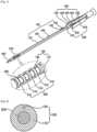
- FIG. 1is a perspective view schematically showing an appearance of a fine surgical instrument capable of performing a joint movement and a rotational movement according to an embodiment of the present disclosure
- FIG. 2is a cross-sectional view of a rod portion showing a wire according to the embodiment of the present disclosure
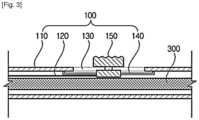
- FIG. 3is a cross-sectional view schematically showing a cross section of a switch
- FIG. 4is a conceptual view showing a shape in which a joint portion is link-rotated in one direction
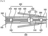
- FIG. 5is a cross-sectional view schematically showing a cross section of a handle portion.
- the fine surgical instrument capable of performing a joint movement and a rotational movementincludes a rod portion 100, a joint portion 200, a shaft 300, a handle portion 400, and a distal end portion 500.
- the fine surgical instrument capable of performing a joint movement and a rotational movementincludes the rod portion 100 which is formed in a longitudinal direction to enter a surgery site in a narrow space, the joint portion 200 which is formed on one side of the rod portion and rotates in one direction, the shaft 300 which is inserted into the rod portion, the handle portion 400 which is coupled with the other side of the rod portion, and the distal end portion 500 which is coupled with one end of the shaft and is connected to the handle portion, in which the distal end portion 500 is operated according to a manipulation of the handle portion 400.
- the rod portion 100may be formed in a tubular shape having a small diameter such that a surgery instrument enters the rod portion 100 without colliding with the endoscope.
- the rod portion 100may include a body 110 and a wire 120.
- the rod portion 100has a small diameter for fine surgery.
- the diameter of the rod portion 100is represented in large in the drawings, it is preferable that the rod portion 100 has the diameter of 2 mm to 3 mm.
- the body 110may be formed in a tubular shape extending in the longitudinal direction. That is, the body 110 may be formed through the center thereof, and the shaft 300 described later may be inserted into the body 110.
- the body 110is formed of a cross section having an edge at a predetermined thickness.
- an insertion holeis formed in a circumferential direction of the cross section.
- the insertion holemay be a space in which the wire 120 is inserted and disposed.
- the wire 120may be formed along the longitudinal direction of the body 110 inside the body 110.
- the wire 120is connected to a switch 150 and the joint portion 200 described later and controls the joint portion 200 by a manipulation of the switch 150. Detailed descriptions thereof will be described with the joint portion 200.
- the rod portion 100further includes a guide groove 130, a guide rail 140, a switch 150, and a washing tube 160.
- the guide groove 130is formed at one side of an outer circumferential surface of the body 110, and the switch 150 described later is located at the guide groove 130.
- the guide rail 140is formed inside the guide groove 130, and the guide rail 140 includes a bar-shaped rail connecting between a protrusion and a protrusion protruding from both inner ends of the guide groove 130.
- the switch 150is coupled with the guide rail 140 and connected to the wire 120.
- the switch 150is located in the guide groove 130, and when the switch moves in one direction along the guide rail 140, the joint portion 200 described later may link-rotate in one direction.
- the washing tube 160is formed on the other side of the outer circumferential surface of the body 110. Moreover, the washing tube 160 communicates with an inside of the washing tube body 110. In addition, the washing tube 160 may have an advantage of removing foreign substances formed in an interior of the body 100 by injecting a washing liquid to the washing tube 130 even in a state where the rod portion 100 is not disassembled.
- the joint portion 200is formed on one side of the rod portion 100 and is rotated in one direction from one side of the rod portion 100.
- the expression "rotated in one direction”indicates bending in one direction.
- the joint portion 200is formed of a plurality of link joints 210.
- the plurality of link joints 210may be provided with a plurality of spherical members, and the spherical members may be disposed in plural at regular intervals.
- the link jointmay include a joint link corresponding to the spherical member.
- the spherical membermay include a spherical insertion hole through which the above-described wire 120 can pass corresponding to the position of the insertion hole so that the wire 120 can pass through the spherical member.
- the through holeis formed to have a diameter corresponding to a diameter of the shaft 300 so that the shaft 300 described later can pass through.
- the joint portion 200can be link-rotated in one direction by the plurality of link joints 210.
- a rotation angle of the joint portion 200can be adjusted by a manipulation of the switch 150. More specifically, one side of the wire 120 is connected to the plurality of link joints 210 and the other side thereof is connected to the switch 150. If the switch 150 is moved in one direction, as the wire 120 is pulled, the joint portion formed by connecting the plurality of link joints 210 to each other is rotated in the direction in which the wire 120 is pulled.
- the joint portion 200is manufactured to be rotatable in one direction, and thus, the distal end portion 500 described later is also rotated in the one direction together.
- the shaft 300is inserted into the rod portion 100, and thus, the shaft 300 can linearly reciprocate inside the rod portion 100 so as to approach the treatment site of the patient during the surgery.
- the shaft 300includes a rod portion 310, a first stopper 320 and a second stopper 330.
- the rod portion 310extends in the longitudinal direction and is formed longer than the rod portion 100, and thus, one side of the rod portion 310 is inserted into the rod portion 100. In addition, the other side of the rod portion 310 is coupled with the handle portion 400 described later.
- the rod portion 310may be made of an elastic material, may pass through the above-described joint portion 200, and can be coupled with the distal end portion 500 described later. Accordingly, the shaft 300 may be rotated in response to the link rotation of the joint portion 200. As the rod part 310 linearly reciprocates inside the rod portion 100, the shaft 300 does not come into direct contact with the treatment side of the patient, and thus, is possible to minimize discomfort of the patient.
- the first stopper 320is formed at a distal end portion of the rod portion 310.
- the first stopper 320is formed to protrude from an outer circumferential surface of the rod portion 310 and functions to limit a movement distance of the connection portion 440 described later.
- the second stopper 330is located to be separated from the first stopper 320.
- the second stopper 330has the same shape as that of the first stopper 320 and is coupled with a spring 450 to be described later. Moreover, the second stopper 330 serves to prevent the spring 450 is separated from the rod portion 310.
- the handle portion 400may be coupled with the one end of the shaft 300 to rotate the shaft 300. Moreover, the handle portion serves to control a manipulation of the distal end portion 500. To this end, the handle portion 400 includes a body portion 410, a sliding groove 420, a grip portion 430, and a connection portion 440.
- the handle portion 400may further include the spring 450.
- the spring 450is disposed inside the body portion 410 and encloses the shaft 300.
- the body portion 410has a tubular shape, is formed to extend in the longitudinal direction, and is coupled with the one end of the shaft 300.
- the sliding grooves 420are formed on both sides of the body portion 410.
- the grip portions 430are formed on both sides of the body portion 410, one side of each of the grip portions 430 is coupled with the body portion 410, and the other side thereof is formed to be separated from the sliding groove 420.
- the grip portions 430are formed in a V shape from a rear end of the body portion 410 in a plan view.
- connection portion 440is connected to an inside of the grip portion 430 and is inserted into the sliding groove 420.
- the connection portion 440includes a connection body 441 which is coupled with the rod portion 310 and is formed in a cylindrical shape, and a connection member 442 which extends from one side of an outer circumferential surface of the connection body 441 and is connected to an inside of the grip portion 430.
- the connection body 441slides in one direction along the rod portion 310 when the grip portions 430 are gripped.
- connection portion 440can be returned to an original position thereof by the spring 450 while the connection portion 440 reciprocates in the shaft 300.
- the distal end portion 500is coupled with the other end of the shaft 300 and is connected to the handle portion 400 to be operated according to the manipulation of the handle portion 400.
- the distal end portion 500may have a forceps ('grab') shape capable of capturing an object of the treatment site or the surgery site.
- the distal end portion 550may be connected to a rear end of the forceps and may include an 'X' shaped bellows link (not shown) to stretch the forceps.
- a distal end of the bellows linkcan be coupled with the other end of the shaft 300.
- a plurality of wiresare provided at the other end of the shaft 300, and the plurality of wires are coupled with the connection body 441.
- a shaft stopping jawmay be formed inside one end of the body 110.
- connection body 441moves in one direction through the sliding groove 420.
- the connection body 441linearly moves in one direction in the rod portion 310.
- the plurality of wires connected to the connection body 441are stretched which pulling the bellows link.
- the distal end portion 500 coupled with the bellows linkcan pick up the treatment site or the surgical site.
- connection body 441releases the stretched bellows link while the connection body 441 is returned to the original position thereof by the spring 450.
- the distal end portion 500can rotate about the shaft 300.
- the fine surgical instrument capable of performing a joint movement and a rotational movementhas an advantage that the joint portion 200 and the handle portion 400 are manipulated such that the instrument can perform a link rotation in one direction and a rotational movement about the shaft 300.
- FIGS. 6 to 9are conceptual views showing a state where a fine surgical instrument capable of performing a joint movement and a rotational movement according to another embodiment of the present disclosure is operated.
- FIGS. 6 to 8similar reference numerals will be given to the same or corresponding components as those of the embodiment, and detailed descriptions of these components will be omitted below.
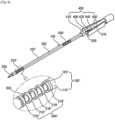
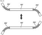
- FIG. 6is a perspective view schematically showing an appearance of the fine surgical instrument capable of performing a joint movement and a rotational movement according to another embodiment of the present disclosure
- FIG. 7is a conceptual view showing a shape in which a pair of joint portions is link-rotated in the same direction
- FIG. 8is a conceptual view showing a shape in which the pair of joint portions is link-rotated in different directions
- FIG. 9is a perspective view schematically showing a shape in which a plurality of link joints and a plurality of wires are coupled.
- the fine surgical instrument capable of performing a joint movement and a rotational movementmay further include a wire 120' which is formed inside the rod portion 100' and the pair of joint portions 200' which is formed on both ends of the rod portion 100'.
- the wire 120'is formed inside the rod portion 100' and may be connected to the pair of joint portions 200'.
- the pair of joint portions 200'is formed on both ends of the rod portion 100', and is preferably formed of a plurality of link joints 210'.
- the plurality of link joints 210'may have a plurality of spherical members and may include joint links corresponding to the spherical members.
- each of the spherical membersmay include an insertion hole through which the above-described wire can pass.
- the pair of joint portions 200'may have an advantage that joint portions 200' can be link-rotated in the same direction or in different directions. In this way, the pair of joint portions 200' has an advantage of facilitating surgery of the user.
- the rod portion 100'has a tubular shape extending in a longitudinal direction, and a plurality of the wires 120' may be formed along the longitudinal direction inside the rod portion 100'. Moreover, a plurality of wires may be coupled with the plurality of link joints 210'.
- the plurality of link joints 210'may have a plurality of spherical members and may include joint links corresponding to the spherical members.
- the spherical membersmay include a plurality of insertion holes through which the plurality of wires can pass.
- FIGS. 10 to 12are conceptual views showing a state where a fine surgical instrument capable of performing a joint movement and a rotational movement according to still another embodiment of the present disclosure is operated.
- FIGS. 10 to 12similar reference numerals will be given to the same or corresponding components as those of the embodiment, and detailed descriptions of these components will be omitted below.
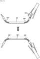
- FIG. 10is a perspective view schematically showing an appearance of the fine surgical instrument capable of performing a joint movement and a rotational movement according to still another embodiment of the present disclosure
- FIG. 11is a conceptual view showing a shape in which a pair of joint portions of FIG. 10 is link-rotated in the same direction
- FIG. 12is a conceptual view showing a shape in which the pair of joint portions of FIG. 10 is link-rotated in different directions.
- the fine surgical instrument capable of performing a joint movement and a rotational movementmay further include the pair of joint portions 200" which is formed on both ends of a rod portion 100".
- the rod portion 100"has a tubular shape extending in a longitudinal direction, and a plurality of the wires may be formed along the longitudinal direction inside the rod portion 100". Moreover, the rod portion 100" include a multi-switch 150" connected to a plurality of wires 120". Meanwhile, the plurality of wires may be coupled with the pair of joint portions 200".
- the pair of joint portions 200"is formed on both ends of the rod portions 100" and includes a plurality of link joints 210".
- the pair of joint portions 200"may have an advantage that the joint portions 200" are link-rotated in the same direction or different directions by moving the multi-switch 150" in one direction or the other direction.
- the pair of joint portions 200"has an advantage of facilitating surgery of the user. That is, when the endoscope and the surgery instrument together enter a narrow space while surgery is performed on a base of a brain through a nasal cavity, the pair of joint portions 200" is link-rotated in respective directions, and thus, it is possible to minimize interference between the endoscope and the surgery instrument. Accordingly, it is possible to freely perform the surgery on the treatment site of the patient.
- the pair of joint portionsis disposed on both sides of the rod portion so as to be link-rotated in each direction, and thus, the fine surgical instrument can be finely manipulated without colliding with the endoscope in a narrow space during the endoscope surgery.
- the fine surgical instrumentcapable of performing a joint movement and a rotational movement of the present disclosure, when the handle portion rotates in one direction, the distal end portion is also rotated in the one direction together, and thus, it is possible to easily control the instrument.
- the fine surgical instrument capable of performing a joint movement and a rotational movement of the present disclosurethe number of drive units and the number of components of the surgical instrument are reduced, and thus, it is possible to secure a price competitiveness of the surgical instrument.
Landscapes
- Health & Medical Sciences (AREA)
- Life Sciences & Earth Sciences (AREA)
- Surgery (AREA)
- Heart & Thoracic Surgery (AREA)
- Engineering & Computer Science (AREA)
- Biomedical Technology (AREA)
- Nuclear Medicine, Radiotherapy & Molecular Imaging (AREA)
- Medical Informatics (AREA)
- Molecular Biology (AREA)
- Animal Behavior & Ethology (AREA)
- General Health & Medical Sciences (AREA)
- Public Health (AREA)
- Veterinary Medicine (AREA)
- Ophthalmology & Optometry (AREA)
- Surgical Instruments (AREA)
Description
- The present disclosure relates to a fine surgical instrument capable of performing a joint movement and a rotational movement, and more particularly, a fine surgical instrument capable of operating an affected part in a narrow area such as an endoscopic operation by finely adjusting a direction and an angle and performing a joint movement and rotational movement.
- In general, in the related art, when cranial surgery, laparotomy, and incision surgery are performed so as to treat a patient, an incision site is large and a lot of blood is lost during surgery. Accordingly, a recovery of the patient after the surgery is slow, a large scar remains after the surgery, which interferes a life of the patient after the surgery. In order to overcome a disadvantage of the laparotomy surgery, in recent years, a new surgical technique such as minimal invasive surgery (MIS) or natural Orifice transluminal endoscopic surgery (NOTES) has been developed.
- The minimal invasive surgery is a surgical technique which incises and treats a minimal portion of a body of a patient using a long and thin surgical tool specifically designed to minimize the incision site required for the surgery, and the natural Orifice transluminal endoscopic surgery is a surgical technique which inserts the surgical tool into a hole (esophagus, anus, vagina, or the like) which naturally presents in a body of a human without incising the body of the patient in order to transfer the surgical tool to a treatment site inside the body of the patient, transfer the surgical tool to the treatment site in the body, and treats the treatment site.
- Compared to the laparotomy, in the minimal invasive surgery and the natural Orifice transluminal endoscopic surgery, the incision site required for the treatment is small, an amount of bleeding during the treatment is very small, a recovery period of the patient after the surgery is fast, and the scar which externally appears is small. Accordingly, in recent years, the number of treatments increases significantly.
- When the minimal invasive surgery and the natural Orifice transluminal endoscopic surgery are performed, a specially designed endoscope device is used to secure a field of view of a surgery site through a minimal body incision. That is, the endoscope device is a medical imaging device for the minimal invasive surgery in which the field of view inside the body of the patient is not directly secured. A doctor and a nurse who perform the minimal invasive surgery perform the surgery while viewing an image of the treatment sites obtained through the endoscope device.
- While the minimal invasive surgery and the natural Orifice transluminal endoscopic surgery are performed, a position and direction of an endoscope should be continuously changed to illuminate a status of the treatment site and a movement of the surgical tool in the body of the patient changed momentarily, as broadly and accurately as possible.
- Moreover, in recent years, the endoscope surgery on a base of a brain has been actively performed in a field of neurosurgery. Although not necessarily in the field of the neurosurgery, the minimal invasive surgery using the endoscopes is developed, and thus, a development of an instrument according to the development of the minimal invasive surgery is urgently required.
- In a case where there is an enough space in an abdominal cavity and the instrument enters through various ports like general surgery, there is no difficulty in performing the surgery even with an instrument having a straight structure. However, in the surgery on the base of the brain through a nose, a size of an entrance is 2 cm or less, and a depth thereof is about 10 cm or more. Because the base of the brain has a very deep and narrow structure, even when the base of the brain can be viewed if the endoscope enters, in most cases, manipulation is not performed using the straight instrument.
- Therefore, in the surgery in the field of the neurosurgery, a surgical device which can continuously change a direction even in a small space is urgently required.
US2014012085A1 discloses a torque-transmitting, variably-flexible device, comprising a hollow body having a proximal end and a distal end, a torque-transmitting element operable to transmit torque from the proximal end towards the distal end of the hollow body, and a steering element operable to steer the distal end of the hollow body.US2012245567A1 discloses a surgical instrument that includes an instrument shaft having proximal and distal ends, a tool disposed from the distal end of the instrument shaft, a control handle disposed from the proximal end of the instrument shaft, a distal motion member for coupling the distal end of the instrument shaft to the tool, a proximal motion member for coupling the proximal end of the instrument shaft to the handle, actuation means extending between the distal and proximal motion members for coupling motion of the proximal motion member to the distal motion member for controlling the positioning of the tool and a locking mechanism for fixing the position of the tool at a selected position and having locked and unlocked states.US2015164524A1 discloses an articulation mechanism for a surgical instrument, including an articulation assembly, a plurality of cables, and a trigger. The cables are coupled to the articulation assembly at a proximal end thereof and extend distally therefrom. The cables are configured to engage an end effector assembly of the surgical instrument at a distal end thereof. The trigger is coupled to the articulation assembly and is selectively moveable from a shipping position to a use position. In the shipping position, the cables are substantially un-tensioned. In the use position, the cables are disposed in an initial tensioned position. In the use position, the trigger is moveable between an unlocked position and a locked position. In the unlocked position, the cables are selectively tensionable to articulate the end effector assembly. In the locked position, the tensions on the cables are maintained to lock the end effector assembly in position.US2012109186A1 discloses an articulating laparoscopic instrument including a handle body, a shaft, an end effector, an operation mechanism, and an articulation mechanism. The end effector is connected to a shaft end. The operation mechanism includes a rod and an actuator. The rod is coupled to the end effector. Movement of the actuator relative to the handle body transfers a force onto the rod in a longitudinal direction to operate the end effector. The articulation mechanism includes a deflection assembly, first and second collar assemblies, first and second cables, a linkage, and an articulation actuator. The first and second collar assemblies are slidably disposed over the rod. The cables extend between the collar assemblies and the deflection assembly. Movement of the articulation actuator drives the first and second collar assemblies in opposite directions to cause a longitudinal deflection in the deflection assembly.DE202012102477U discloses an electrosurgical instrument having an energizable bipolar that is provided with two grumbling portions. The grumbling portions are mechanically adjusted through an axially adjustable pull bar. The pull bar is received in an axially extending sleeve and is detachably connected in a slide portion of a gripping portion. The steering wheels are formed with slide portion. The slide portion is connected to grip shells. The grip shells are arranged on the left and right side of the pull bar and are moved laterally to the adjustment direction.- The present disclosure is made to solve the above-described problems of the related art, and provides a fine surgical instrument capable of performing a joint movement and a rotational movement, in which a distal end of the instrument is link-rotated when surgery such as endoscope surgery is performed in a narrow space and the instrument is freely manipulated without colliding with an endoscope.
- The present invention is directed to a fine surgical instrument as set out in claim 1. Optional features are set out in the dependent claims.
FIG. 1 is a perspective view schematically showing an appearance of a fine surgical instrument capable of performing a joint movement and a rotational movement according to an embodiment of the present disclosure.FIG. 2 is a cross-sectional view of a rod portion showing a wire according to the embodiment of the present disclosure.FIG. 3 is a cross-sectional view schematically showing a cross section of a switch.FIG. 4 is a conceptual view showing a shape in which a joint portion is link-rotated in one direction.FIG. 5 is a cross-sectional view schematically showing a cross section of a handle portion.FIG. 6 is a perspective view schematically showing an appearance of a fine surgical instrument capable of performing a joint movement and a rotational movement according to another embodiment of the present disclosure.FIG. 7 is a conceptual view showing a shape in which a pair of joint portions is link-rotated in the same direction.FIG. 8 is a conceptual view showing a shape in which the pair of joint portions is link-rotated in different directions.FIG. 9 is a perspective view schematically showing a shape in which a plurality of link joints and a plurality of wires are coupled.FIG. 10 is a perspective view schematically showing an appearance of a fine surgical instrument capable of performing a joint movement and a rotational movement according to still another embodiment of the present disclosure.FIG. 11 is a conceptual view showing a shape in which a pair of joint portions ofFIG. 10 is link-rotated in the same direction.FIG. 12 is a conceptual view showing a shape in which the pair of joint portions ofFIG. 10 is link-rotated in different directions.FIG. 1 Hereinafter, preferred embodiments of the present disclosure will be described in detail with reference to the accompanying drawings. First, in adding reference numerals to the components of each drawing, it should be noted that the same reference numerals are used as much as possible even if shown on different drawings. Moreover, in descriptions of the present disclosure, if it is determined that detailed descriptions of known related configurations or functions may obscure a subject matter of the present disclosure, detailed descriptions thereof will be omitted.- Throughout the specification, when a portion is "connected" to another portion, it includes not only "direct connection" but also "indirect connection" via another member therebetween. In addition, when a portion is said to "include" a certain component, this means that unless otherwise stated, it may further include other components rather than excluding the other components.
- Moreover, a fine surgical instrument capable of performing a joint movement and a rotational movement according to an embodiment of the present disclosure may be applied to laparoscopic surgery using an endoscope and minimal invasive surgery using an endoscope. Moreover, a fine surgical instrument capable of performing a joint movement and a rotational movement according to an embodiment of the present disclosure may be applied to surgery on a base of a brain through a nasal cavity. In addition, a fine surgical instrument capable of performing a joint movement and a rotational movement according to an embodiment of the present disclosure may be applied to other non-claimed instruments such as a catheter and a medical instrument including diagnostic and therapeutic instruments and tools.
FIG. 1 is a perspective view schematically showing an appearance of a fine surgical instrument capable of performing a joint movement and a rotational movement according to an embodiment of the present disclosure,FIG. 2 is a cross-sectional view of a rod portion showing a wire according to the embodiment of the present disclosure,FIG. 3 is a cross-sectional view schematically showing a cross section of a switch,FIG. 4 is a conceptual view showing a shape in which a joint portion is link-rotated in one direction, andFIG. 5 is a cross-sectional view schematically showing a cross section of a handle portion.- As shown in
FIGS. 1 to 5 , the fine surgical instrument capable of performing a joint movement and a rotational movement according to an embodiment of the present disclosure includes arod portion 100, ajoint portion 200, ashaft 300, ahandle portion 400, and adistal end portion 500. - More specifically, the fine surgical instrument capable of performing a joint movement and a rotational movement according to the embodiment of the present disclosure includes the
rod portion 100 which is formed in a longitudinal direction to enter a surgery site in a narrow space, thejoint portion 200 which is formed on one side of the rod portion and rotates in one direction, theshaft 300 which is inserted into the rod portion, thehandle portion 400 which is coupled with the other side of the rod portion, and thedistal end portion 500 which is coupled with one end of the shaft and is connected to the handle portion, in which thedistal end portion 500 is operated according to a manipulation of thehandle portion 400. - Hereinafter, the fine surgical instrument capable of performing a joint movement and a rotational movement according to the embodiment of the present disclosure will be described in more detail with reference to
FIGS. 1 and 2 . - The
rod portion 100 may be formed in a tubular shape having a small diameter such that a surgery instrument enters therod portion 100 without colliding with the endoscope. To this end, therod portion 100 may include abody 110 and awire 120. In addition, it is preferable that therod portion 100 has a small diameter for fine surgery. Although the diameter of therod portion 100 is represented in large in the drawings, it is preferable that therod portion 100 has the diameter of 2 mm to 3 mm. - The
body 110 may be formed in a tubular shape extending in the longitudinal direction. That is, thebody 110 may be formed through the center thereof, and theshaft 300 described later may be inserted into thebody 110. Referring toFIG. 2 , thebody 110 is formed of a cross section having an edge at a predetermined thickness. In addition, an insertion hole is formed in a circumferential direction of the cross section. Here, the insertion hole may be a space in which thewire 120 is inserted and disposed. - The
wire 120 may be formed along the longitudinal direction of thebody 110 inside thebody 110. In addition, thewire 120 is connected to aswitch 150 and thejoint portion 200 described later and controls thejoint portion 200 by a manipulation of theswitch 150. Detailed descriptions thereof will be described with thejoint portion 200. - In addition, the
rod portion 100 further includes aguide groove 130, aguide rail 140, aswitch 150, and awashing tube 160. - The
guide groove 130 is formed at one side of an outer circumferential surface of thebody 110, and theswitch 150 described later is located at theguide groove 130. - The
guide rail 140 is formed inside theguide groove 130, and theguide rail 140 includes a bar-shaped rail connecting between a protrusion and a protrusion protruding from both inner ends of theguide groove 130. - The
switch 150 is coupled with theguide rail 140 and connected to thewire 120. In addition, theswitch 150 is located in theguide groove 130, and when the switch moves in one direction along theguide rail 140, thejoint portion 200 described later may link-rotate in one direction. - The
washing tube 160 is formed on the other side of the outer circumferential surface of thebody 110. Moreover, thewashing tube 160 communicates with an inside of thewashing tube body 110. In addition, thewashing tube 160 may have an advantage of removing foreign substances formed in an interior of thebody 100 by injecting a washing liquid to thewashing tube 130 even in a state where therod portion 100 is not disassembled. - In the fine surgical instrument capable of performing a joint movement and a rotational movement according to the embodiment of the present disclosure, the
joint portion 200 is formed on one side of therod portion 100 and is rotated in one direction from one side of therod portion 100. Here, the expression "rotated in one direction" indicates bending in one direction. It is preferable that thejoint portion 200 is formed of a plurality of link joints 210. For example, the plurality oflink joints 210 may be provided with a plurality of spherical members, and the spherical members may be disposed in plural at regular intervals. In addition, the link joint may include a joint link corresponding to the spherical member. Moreover, the spherical member may include a spherical insertion hole through which the above-describedwire 120 can pass corresponding to the position of the insertion hole so that thewire 120 can pass through the spherical member. In addition, it is preferably that the through hole is formed to have a diameter corresponding to a diameter of theshaft 300 so that theshaft 300 described later can pass through. - As shown in
FIGS. 5 and6 , thejoint portion 200 can be link-rotated in one direction by the plurality of link joints 210. In other words, in thejoint portion 200, a rotation angle of thejoint portion 200 can be adjusted by a manipulation of theswitch 150. More specifically, one side of thewire 120 is connected to the plurality oflink joints 210 and the other side thereof is connected to theswitch 150. If theswitch 150 is moved in one direction, as thewire 120 is pulled, the joint portion formed by connecting the plurality oflink joints 210 to each other is rotated in the direction in which thewire 120 is pulled. - Meanwhile, if the
switch 150 is moved in the other direction, the pulledwire 120 is released, and thejoint portion 200 is returned to an original position thereof by an elastic force of theshaft 300. - In this way, the
joint portion 200 is manufactured to be rotatable in one direction, and thus, thedistal end portion 500 described later is also rotated in the one direction together. - In the fine surgical instrument capable of performing a joint movement and a rotational movement according to the embodiment of the present disclosure, the
shaft 300 is inserted into therod portion 100, and thus, theshaft 300 can linearly reciprocate inside therod portion 100 so as to approach the treatment site of the patient during the surgery. In this end, theshaft 300 includes arod portion 310, afirst stopper 320 and asecond stopper 330. - The
rod portion 310 extends in the longitudinal direction and is formed longer than therod portion 100, and thus, one side of therod portion 310 is inserted into therod portion 100. In addition, the other side of therod portion 310 is coupled with thehandle portion 400 described later. - Here, the
rod portion 310 may be made of an elastic material, may pass through the above-describedjoint portion 200, and can be coupled with thedistal end portion 500 described later. Accordingly, theshaft 300 may be rotated in response to the link rotation of thejoint portion 200. As therod part 310 linearly reciprocates inside therod portion 100, theshaft 300 does not come into direct contact with the treatment side of the patient, and thus, is possible to minimize discomfort of the patient. - The
first stopper 320 is formed at a distal end portion of therod portion 310. In addition, thefirst stopper 320 is formed to protrude from an outer circumferential surface of therod portion 310 and functions to limit a movement distance of theconnection portion 440 described later. - The
second stopper 330 is located to be separated from thefirst stopper 320. Thesecond stopper 330 has the same shape as that of thefirst stopper 320 and is coupled with aspring 450 to be described later. Moreover, thesecond stopper 330 serves to prevent thespring 450 is separated from therod portion 310. - In the fine surgical instrument capable of performing a joint movement and a rotational movement according to the embodiment of the present disclosure, the
handle portion 400 may be coupled with the one end of theshaft 300 to rotate theshaft 300. Moreover, the handle portion serves to control a manipulation of thedistal end portion 500. To this end, thehandle portion 400 includes abody portion 410, a slidinggroove 420, agrip portion 430, and aconnection portion 440. - In addition, the
handle portion 400 may further include thespring 450. Here, thespring 450 is disposed inside thebody portion 410 and encloses theshaft 300. - Referring to
FIGS. 1 and5 , thebody portion 410 has a tubular shape, is formed to extend in the longitudinal direction, and is coupled with the one end of theshaft 300. - The sliding
grooves 420 are formed on both sides of thebody portion 410. - The
grip portions 430 are formed on both sides of thebody portion 410, one side of each of thegrip portions 430 is coupled with thebody portion 410, and the other side thereof is formed to be separated from the slidinggroove 420. In addition, thegrip portions 430 are formed in a V shape from a rear end of thebody portion 410 in a plan view. - The
connection portion 440 is connected to an inside of thegrip portion 430 and is inserted into the slidinggroove 420. In other words, theconnection portion 440 includes aconnection body 441 which is coupled with therod portion 310 and is formed in a cylindrical shape, and aconnection member 442 which extends from one side of an outer circumferential surface of theconnection body 441 and is connected to an inside of thegrip portion 430. Theconnection body 441 slides in one direction along therod portion 310 when thegrip portions 430 are gripped. - Meanwhile, when the gripped
grip portion 430 is released, theconnection portion 440 can be returned to an original position thereof by thespring 450 while theconnection portion 440 reciprocates in theshaft 300. - The
distal end portion 500 is coupled with the other end of theshaft 300 and is connected to thehandle portion 400 to be operated according to the manipulation of thehandle portion 400. - More specifically, the
distal end portion 500 may have a forceps ('grab') shape capable of capturing an object of the treatment site or the surgery site. Moreover, the distal end portion 550 may be connected to a rear end of the forceps and may include an 'X' shaped bellows link (not shown) to stretch the forceps. In this case, a distal end of the bellows link can be coupled with the other end of theshaft 300. A plurality of wires are provided at the other end of theshaft 300, and the plurality of wires are coupled with theconnection body 441. - Meanwhile, in order to prevent the other end of the
shaft 300 from protruding from therod portion 100, a shaft stopping jaw may be formed inside one end of thebody 110. - Accordingly, when the
distal end portion 500 grips thegrip 430, theconnection body 441 moves in one direction through the slidinggroove 420. In this case, theconnection body 441 linearly moves in one direction in therod portion 310. Moreover, the plurality of wires connected to theconnection body 441 are stretched which pulling the bellows link. In this case, thedistal end portion 500 coupled with the bellows link can pick up the treatment site or the surgical site. - In addition, when the
grip part 430 is released, the plurality of wires connected to theconnection body 441 releases the stretched bellows link while theconnection body 441 is returned to the original position thereof by thespring 450. - Meanwhile, when the
handle portion 400 is rotated in one direction, thedistal end portion 500 can rotate about theshaft 300. - Accordingly, the fine surgical instrument capable of performing a joint movement and a rotational movement according to the embodiment of the present disclosure has an advantage that the
joint portion 200 and thehandle portion 400 are manipulated such that the instrument can perform a link rotation in one direction and a rotational movement about theshaft 300. FIGS. 6 to 9 are conceptual views showing a state where a fine surgical instrument capable of performing a joint movement and a rotational movement according to another embodiment of the present disclosure is operated.- In the fine surgical instrument capable of performing a joint movement and a rotational movement according to another embodiment of the present disclosure, the above descriptions are referred to the same components as the components of the above-described embodiment, a rod portion 100' and a joint portion 200' which are modified components will be described in more detail.
- Therefore, in
FIGS. 6 to 8 , similar reference numerals will be given to the same or corresponding components as those of the embodiment, and detailed descriptions of these components will be omitted below. FIG. 6 is a perspective view schematically showing an appearance of the fine surgical instrument capable of performing a joint movement and a rotational movement according to another embodiment of the present disclosure,FIG. 7 is a conceptual view showing a shape in which a pair of joint portions is link-rotated in the same direction,FIG. 8 is a conceptual view showing a shape in which the pair of joint portions is link-rotated in different directions, andFIG. 9 is a perspective view schematically showing a shape in which a plurality of link joints and a plurality of wires are coupled.- Referring to
FIG. 6 , the fine surgical instrument capable of performing a joint movement and a rotational movement according to another embodiment of the present disclosure may further include a wire 120' which is formed inside the rod portion 100' and the pair of joint portions 200' which is formed on both ends of the rod portion 100'. - The wire 120' is formed inside the rod portion 100' and may be connected to the pair of joint portions 200'.
- The pair of joint portions 200' is formed on both ends of the rod portion 100', and is preferably formed of a plurality of link joints 210'.
- For example, the plurality of link joints 210' may have a plurality of spherical members and may include joint links corresponding to the spherical members. In addition, each of the spherical members may include an insertion hole through which the above-described wire can pass.
- As shown in
FIG. 7 andFIG. 8 , the pair of joint portions 200' may have an advantage that joint portions 200' can be link-rotated in the same direction or in different directions. In this way, the pair of joint portions 200' has an advantage of facilitating surgery of the user. - As shown in
FIG. 9 , the rod portion 100' has a tubular shape extending in a longitudinal direction, and a plurality of the wires 120' may be formed along the longitudinal direction inside the rod portion 100'. Moreover, a plurality of wires may be coupled with the plurality of link joints 210'. - For example, the plurality of link joints 210' may have a plurality of spherical members and may include joint links corresponding to the spherical members. In addition, the spherical members may include a plurality of insertion holes through which the plurality of wires can pass.
FIGS. 10 to 12 are conceptual views showing a state where a fine surgical instrument capable of performing a joint movement and a rotational movement according to still another embodiment of the present disclosure is operated.- In the fine surgical instrument capable of performing a joint movement and a rotational movement according to still another embodiment of the present disclosure, the above descriptions are referred to the same components as the components of the above-described embodiment, a pair of
joint portions 200" which is a modified component will be described in more detail. - Therefore, in
FIGS. 10 to 12 , similar reference numerals will be given to the same or corresponding components as those of the embodiment, and detailed descriptions of these components will be omitted below. FIG. 10 is a perspective view schematically showing an appearance of the fine surgical instrument capable of performing a joint movement and a rotational movement according to still another embodiment of the present disclosure,FIG. 11 is a conceptual view showing a shape in which a pair of joint portions ofFIG. 10 is link-rotated in the same direction, andFIG. 12 is a conceptual view showing a shape in which the pair of joint portions ofFIG. 10 is link-rotated in different directions.- Referring to
FIG. 10 , the fine surgical instrument capable of performing a joint movement and a rotational movement according to still another embodiment of the present disclosure may further include the pair ofjoint portions 200" which is formed on both ends of arod portion 100". - The
rod portion 100" has a tubular shape extending in a longitudinal direction, and a plurality of the wires may be formed along the longitudinal direction inside therod portion 100". Moreover, therod portion 100" include a multi-switch 150" connected to a plurality ofwires 120". Meanwhile, the plurality of wires may be coupled with the pair ofjoint portions 200". - It is preferable that the pair of
joint portions 200" is formed on both ends of therod portions 100" and includes a plurality oflink joints 210". - As shown in
FIGS. 10 and11 , the pair ofjoint portions 200" may have an advantage that thejoint portions 200" are link-rotated in the same direction or different directions by moving the multi-switch 150" in one direction or the other direction. - In this way, the pair of
joint portions 200" has an advantage of facilitating surgery of the user. That is, when the endoscope and the surgery instrument together enter a narrow space while surgery is performed on a base of a brain through a nasal cavity, the pair ofjoint portions 200" is link-rotated in respective directions, and thus, it is possible to minimize interference between the endoscope and the surgery instrument. Accordingly, it is possible to freely perform the surgery on the treatment site of the patient. - The above-described description of the present disclosure is for illustrative purposes, and it will be understood by those skilled in the art that the present disclosure can be easily modified into other specific forms without changing a technical spirit or essential characteristics of the present disclosure. Therefore, it should be understood that the above-described embodiments are exemplary in all respects and not restrictive. For example, each component described as a single type may be implemented in a distributed manner, and similarly, components described as distributed may be implemented in a coupled form.
- The scope of the present disclosure is indicated by the following claims, and all changes or modifications derived from the meaning and scope of the claims and their equivalent concepts should be interpreted as being included in the scope of the present disclosure.
- According the fine surgical instrument capable of performing a joint movement and a rotational movement of the present disclosure, the pair of joint portions is disposed on both sides of the rod portion so as to be link-rotated in each direction, and thus, the fine surgical instrument can be finely manipulated without colliding with the endoscope in a narrow space during the endoscope surgery.
- In addition, according the fine surgical instrument capable of performing a joint movement and a rotational movement of the present disclosure, when the handle portion rotates in one direction, the distal end portion is also rotated in the one direction together, and thus, it is possible to easily control the instrument.
- Moreover, according the fine surgical instrument capable of performing a joint movement and a rotational movement of the present disclosure, the number of drive units and the number of components of the surgical instrument are reduced, and thus, it is possible to secure a price competitiveness of the surgical instrument.
Claims (12)
- A fine surgical instrument capable of performing a joint movement and a rotational movement, the fine surgical instrument comprising:a rod portion (100, 100', 100") which is formed in a longitudinal direction to enter a surgery site located in a narrow space;a joint portion (200, 200', 200") which is formed on one side of the rod portion (100, 100', 100") and which is configured to rotate in one direction from the one side of the rod portion (100, 100', 100");a shaft (300) which is inserted into the rod portion (100, 100', 100") and which is provided with a rod (300) including a rod portion (310);a handle portion (400) which is coupled with the other side of the rod portion (100, 100', 100"); anda distal end portion (500) which is coupled with one end of the shaft (300) and is connected to the handle portion (400),wherein the distal end portion (500) is operated along a manipulation of the handle portion (400),wherein the handle portion (400) includes a tubular body portion (410), sliding grooves (420) which are formed on both sides of the body portion (410), a grip portion (430) of which one side is coupled with the body portion (410) and the other side is formed to be separated from the sliding grooves (420), a connection portion (440) which is connected to an inside of the grip portion (430) and is inserted into the sliding grooves (420), and a spring (450) which is inserted into the body portion (410),wherein the connection portion (440) includes a connection body (441) which is coupled with the rod portion (310) and is formed in a cylindrical shape, and a connection member (442) which extends from one side of an outer circumferential surface of the connection body (441) and is connected to the inside of the grip portion (430), andwherein the connection body (441) slides in one direction along the rod portion (310) when the grip portion (430) is gripped.
- The fine surgical instrument of claim 1, wherein the rod portion (100, 100', 100") is a tubular body extending in the longitudinal direction and includes a wire (120, 120', 120") formed inside the body.
- The fine surgical instrument of claim 2, wherein the rod portion (100, 100', 100") further includes a guide groove (130) which is formed on one side of an outer peripheral surface of the body, a guide rail (140) which is formed inside the guide groove (130), a switch (150) which is coupled with the guide rail (140) and is connected to the wire (120, 120', 120"), and a washing tube (160) which is formed on the other side of the outer peripheral surface of the body.
- The fine surgical instrument of claim 1, wherein the joint portion (200, 200', 200") includes a plurality of link joints (210, 210', 210").
- The fine surgical instrument of claim 3, wherein when the switch (150) moves in one direction, the joint portion (200, 200', 200") is link-rotated in one direction.
- The fine surgical instrument of claim 4, wherein the shaft (300) includes a first stopper (320) which is formed at a distal end portion of the rod portion (310), and a second stopper (330) which is located to be separated from the first stopper (320).
- The fine surgical instrument of claim 6, wherein the rod portion (310) is formed of an elastic material.
- The fine surgical instrument of claim 1, wherein the distal end portion (500) rotates about the shaft (300) when the handle portion (400) rotates in one direction.
- The fine surgical instrument of claim 1, further comprising:a wire (120, 120', 120") which is formed inside the rod portion (100, 100', 100"); anda pair of joint portions (200, 200', 200") which is formed on both ends of the rod portion (100, 100', 100").
- The fine surgical instrument of claim 9, wherein a plurality of the wires (120, 120, 120") may be formed along the longitudinal direction inside the rod portion (100, 100', 100").
- The fine surgical instrument of claim 9, wherein the pair of joint portions (200, 200', 200") includes a plurality of link joints (210, 210', 210").
- The fine surgical instrument of claim 11, wherein the plurality of link joints (210, 210', 210") are coupled with the plurality of wires (120, 120', 120").
Applications Claiming Priority (2)
| Application Number | Priority Date | Filing Date | Title |
|---|---|---|---|
| KR1020170056978AKR102347945B1 (en) | 2017-05-04 | 2017-05-04 | Surgical instrument equipment appropriate for mini-invasive surgery |
| PCT/KR2018/005129WO2018203675A1 (en) | 2017-05-04 | 2018-05-03 | Microsurgical instrument capable of joint motion and rotational motion |
Publications (3)
| Publication Number | Publication Date |
|---|---|
| EP3636163A1 EP3636163A1 (en) | 2020-04-15 |
| EP3636163A4 EP3636163A4 (en) | 2021-01-20 |
| EP3636163B1true EP3636163B1 (en) | 2023-10-25 |
Family
ID=64016105
Family Applications (1)
| Application Number | Title | Priority Date | Filing Date |
|---|---|---|---|
| EP18794619.9AActiveEP3636163B1 (en) | 2017-05-04 | 2018-05-03 | Microsurgical instrument capable of joint motion and rotational motion |
Country Status (3)
| Country | Link |
|---|---|
| EP (1) | EP3636163B1 (en) |
| KR (1) | KR102347945B1 (en) |
| WO (1) | WO2018203675A1 (en) |
Families Citing this family (8)
| Publication number | Priority date | Publication date | Assignee | Title |
|---|---|---|---|---|
| WO2020256502A2 (en)* | 2019-06-21 | 2020-12-24 | 한국과학기술원 | Gripper and surgical master device comprising same |
| KR102283670B1 (en) | 2019-06-21 | 2021-07-30 | 한국과학기술원 | Master device for surgery to control slave device |
| KR102285586B1 (en) | 2019-06-21 | 2021-08-04 | 한국과학기술원 | Gripper used in master device for surgery |
| CN110403676B (en)* | 2019-08-29 | 2024-06-18 | 苏州碧利医疗科技有限公司 | A detachable microscissors |
| US12042166B2 (en) | 2020-09-22 | 2024-07-23 | Boston Scientific Medical Device Limited | Medical articulation devices and methods of using the same |
| KR102643289B1 (en) | 2021-09-11 | 2024-03-05 | 주식회사 화인메디 | Surgical medical device |
| CN115363698B (en)* | 2022-08-31 | 2024-03-22 | 精勤智造(苏州)医疗科技有限公司 | Wire drive movement module and minimally invasive surgical forceps |
| CN115414092B (en)* | 2022-08-31 | 2025-07-22 | 精勤智造(苏州)医疗科技有限公司 | Wire drive movement module and minimally invasive surgical forceps |
Citations (1)
| Publication number | Priority date | Publication date | Assignee | Title |
|---|---|---|---|---|
| DE202012102477U1 (en)* | 2012-07-04 | 2013-10-08 | Dausch Medizintechnik Gmbh | Electrosurgical instrument |
Family Cites Families (10)
| Publication number | Priority date | Publication date | Assignee | Title |
|---|---|---|---|---|
| US5976164A (en)* | 1996-09-13 | 1999-11-02 | Eclipse Surgical Technologies, Inc. | Method and apparatus for myocardial revascularization and/or biopsy of the heart |
| US7468041B2 (en)* | 2003-06-26 | 2008-12-23 | Depuy Products, Inc. | Modular surgical instrument with reciprocable implement |
| US7686826B2 (en)* | 2003-10-30 | 2010-03-30 | Cambridge Endoscopic Devices, Inc. | Surgical instrument |
| US9155451B2 (en)* | 2006-03-02 | 2015-10-13 | Syntheon, Llc | Variably flexible insertion device and method for variably flexing an insertion device |
| US7648519B2 (en)* | 2006-09-13 | 2010-01-19 | Cambridge Endoscopic Devices, Inc. | Surgical instrument |
| US8968355B2 (en)* | 2008-08-04 | 2015-03-03 | Covidien Lp | Articulating surgical device |
| US20120109186A1 (en)* | 2010-10-29 | 2012-05-03 | Parrott David A | Articulating laparoscopic surgical instruments |
| KR101259690B1 (en)* | 2011-03-31 | 2013-05-02 | 정창욱 | Instrument for Minimally Invasive Surgery Having Shaft Including Inner Torque Transmission Member |
| KR101322030B1 (en)* | 2011-09-05 | 2013-10-28 | 주식회사 모바수 | Instrument for Minimally Invasive Surgery Having Articulation Unit Including Spherical Parts |
| KR101586177B1 (en)* | 2015-08-17 | 2016-01-22 | 윤영석 | A apparatus for puncturing maxillary sinus |
- 2017
- 2017-05-04KRKR1020170056978Apatent/KR102347945B1/enactiveActive
- 2018
- 2018-05-03EPEP18794619.9Apatent/EP3636163B1/enactiveActive
- 2018-05-03WOPCT/KR2018/005129patent/WO2018203675A1/ennot_activeCeased
Patent Citations (1)
| Publication number | Priority date | Publication date | Assignee | Title |
|---|---|---|---|---|
| DE202012102477U1 (en)* | 2012-07-04 | 2013-10-08 | Dausch Medizintechnik Gmbh | Electrosurgical instrument |
Also Published As
| Publication number | Publication date |
|---|---|
| EP3636163A4 (en) | 2021-01-20 |
| KR102347945B1 (en) | 2022-01-06 |
| EP3636163A1 (en) | 2020-04-15 |
| WO2018203675A1 (en) | 2018-11-08 |
| KR20180122845A (en) | 2018-11-14 |
Similar Documents
| Publication | Publication Date | Title |
|---|---|---|
| EP3636163B1 (en) | Microsurgical instrument capable of joint motion and rotational motion | |
| US12089826B2 (en) | Articulation joint with bending member | |
| US10813538B2 (en) | Articulation section with locking | |
| US9861272B2 (en) | Apparatus, systems, and methods for performing laparoscopic surgery | |
| US20250009455A1 (en) | Medical tools having tension bands | |
| EP2378987B1 (en) | Steerable surgical access devices | |
| JP5188811B2 (en) | Manual device for remote control of gripping tools | |
| US8246575B2 (en) | Flexible hollow spine with locking feature and manipulation structure | |
| US20090259141A1 (en) | Steerable tool guide for use with flexible endoscopic medical devices | |
| US20110196418A1 (en) | Flexible medical instruments | |
| US20100249497A1 (en) | Surgical instrument | |
| US11006936B2 (en) | Control assemblies for medical devices and related methods of use | |
| KR20150119931A (en) | Steerable medical device | |
| JP2023154104A (en) | Articulating microsurgical instrument | |
| KR20130009121A (en) | Instrument for minimally invasive surgery that can selectively cover its end effector | |
| US20220202433A1 (en) | Control mechanism for end effectors and method of use | |
| KR20240058616A (en) | Medical end effector with elastic forceps | |
| CN116942258A (en) | Linked surgical instruments |
Legal Events
| Date | Code | Title | Description |
|---|---|---|---|
| STAA | Information on the status of an ep patent application or granted ep patent | Free format text:STATUS: THE INTERNATIONAL PUBLICATION HAS BEEN MADE | |
| PUAI | Public reference made under article 153(3) epc to a published international application that has entered the european phase | Free format text:ORIGINAL CODE: 0009012 | |
| STAA | Information on the status of an ep patent application or granted ep patent | Free format text:STATUS: REQUEST FOR EXAMINATION WAS MADE | |
| 17P | Request for examination filed | Effective date:20191202 | |
| AK | Designated contracting states | Kind code of ref document:A1 Designated state(s):AL AT BE BG CH CY CZ DE DK EE ES FI FR GB GR HR HU IE IS IT LI LT LU LV MC MK MT NL NO PL PT RO RS SE SI SK SM TR | |
| AX | Request for extension of the european patent | Extension state:BA ME | |
| DAV | Request for validation of the european patent (deleted) | ||
| DAX | Request for extension of the european patent (deleted) | ||
| A4 | Supplementary search report drawn up and despatched | Effective date:20201222 | |
| RIC1 | Information provided on ipc code assigned before grant | Ipc:A61B 17/29 20060101ALI20201216BHEP Ipc:A61B 17/00 20060101AFI20201216BHEP | |
| GRAP | Despatch of communication of intention to grant a patent | Free format text:ORIGINAL CODE: EPIDOSNIGR1 | |
| STAA | Information on the status of an ep patent application or granted ep patent | Free format text:STATUS: GRANT OF PATENT IS INTENDED | |
| RIC1 | Information provided on ipc code assigned before grant | Ipc:A61B 17/30 20060101ALI20230419BHEP Ipc:A61B 17/29 20060101ALI20230419BHEP Ipc:A61B 17/00 20060101AFI20230419BHEP | |
| INTG | Intention to grant announced | Effective date:20230509 | |
| GRAS | Grant fee paid | Free format text:ORIGINAL CODE: EPIDOSNIGR3 | |
| GRAA | (expected) grant | Free format text:ORIGINAL CODE: 0009210 | |
| STAA | Information on the status of an ep patent application or granted ep patent | Free format text:STATUS: THE PATENT HAS BEEN GRANTED | |
| AK | Designated contracting states | Kind code of ref document:B1 Designated state(s):AL AT BE BG CH CY CZ DE DK EE ES FI FR GB GR HR HU IE IS IT LI LT LU LV MC MK MT NL NO PL PT RO RS SE SI SK SM TR | |
| REG | Reference to a national code | Ref country code:GB Ref legal event code:FG4D | |
| REG | Reference to a national code | Ref country code:CH Ref legal event code:EP | |
| REG | Reference to a national code | Ref country code:DE Ref legal event code:R096 Ref document number:602018060047 Country of ref document:DE | |
| REG | Reference to a national code | Ref country code:IE Ref legal event code:FG4D | |
| P01 | Opt-out of the competence of the unified patent court (upc) registered | Effective date:20231021 | |
| REG | Reference to a national code | Ref country code:LT Ref legal event code:MG9D | |
| REG | Reference to a national code | Ref country code:NL Ref legal event code:MP Effective date:20231025 | |
| REG | Reference to a national code | Ref country code:AT Ref legal event code:MK05 Ref document number:1623840 Country of ref document:AT Kind code of ref document:T Effective date:20231025 | |
| PG25 | Lapsed in a contracting state [announced via postgrant information from national office to epo] | Ref country code:NL Free format text:LAPSE BECAUSE OF FAILURE TO SUBMIT A TRANSLATION OF THE DESCRIPTION OR TO PAY THE FEE WITHIN THE PRESCRIBED TIME-LIMIT Effective date:20231025 | |
| PG25 | Lapsed in a contracting state [announced via postgrant information from national office to epo] | Ref country code:GR Free format text:LAPSE BECAUSE OF FAILURE TO SUBMIT A TRANSLATION OF THE DESCRIPTION OR TO PAY THE FEE WITHIN THE PRESCRIBED TIME-LIMIT Effective date:20240126 | |
| PG25 | Lapsed in a contracting state [announced via postgrant information from national office to epo] | Ref country code:IS Free format text:LAPSE BECAUSE OF FAILURE TO SUBMIT A TRANSLATION OF THE DESCRIPTION OR TO PAY THE FEE WITHIN THE PRESCRIBED TIME-LIMIT Effective date:20240225 | |
| PG25 | Lapsed in a contracting state [announced via postgrant information from national office to epo] | Ref country code:LT Free format text:LAPSE BECAUSE OF FAILURE TO SUBMIT A TRANSLATION OF THE DESCRIPTION OR TO PAY THE FEE WITHIN THE PRESCRIBED TIME-LIMIT Effective date:20231025 | |
| PG25 | Lapsed in a contracting state [announced via postgrant information from national office to epo] | Ref country code:AT Free format text:LAPSE BECAUSE OF FAILURE TO SUBMIT A TRANSLATION OF THE DESCRIPTION OR TO PAY THE FEE WITHIN THE PRESCRIBED TIME-LIMIT Effective date:20231025 | |
| PG25 | Lapsed in a contracting state [announced via postgrant information from national office to epo] | Ref country code:ES Free format text:LAPSE BECAUSE OF FAILURE TO SUBMIT A TRANSLATION OF THE DESCRIPTION OR TO PAY THE FEE WITHIN THE PRESCRIBED TIME-LIMIT Effective date:20231025 | |
| PG25 | Lapsed in a contracting state [announced via postgrant information from national office to epo] | Ref country code:LT Free format text:LAPSE BECAUSE OF FAILURE TO SUBMIT A TRANSLATION OF THE DESCRIPTION OR TO PAY THE FEE WITHIN THE PRESCRIBED TIME-LIMIT Effective date:20231025 Ref country code:IS Free format text:LAPSE BECAUSE OF FAILURE TO SUBMIT A TRANSLATION OF THE DESCRIPTION OR TO PAY THE FEE WITHIN THE PRESCRIBED TIME-LIMIT Effective date:20240225 Ref country code:GR Free format text:LAPSE BECAUSE OF FAILURE TO SUBMIT A TRANSLATION OF THE DESCRIPTION OR TO PAY THE FEE WITHIN THE PRESCRIBED TIME-LIMIT Effective date:20240126 Ref country code:ES Free format text:LAPSE BECAUSE OF FAILURE TO SUBMIT A TRANSLATION OF THE DESCRIPTION OR TO PAY THE FEE WITHIN THE PRESCRIBED TIME-LIMIT Effective date:20231025 Ref country code:BG Free format text:LAPSE BECAUSE OF FAILURE TO SUBMIT A TRANSLATION OF THE DESCRIPTION OR TO PAY THE FEE WITHIN THE PRESCRIBED TIME-LIMIT Effective date:20240125 Ref country code:AT Free format text:LAPSE BECAUSE OF FAILURE TO SUBMIT A TRANSLATION OF THE DESCRIPTION OR TO PAY THE FEE WITHIN THE PRESCRIBED TIME-LIMIT Effective date:20231025 Ref country code:PT Free format text:LAPSE BECAUSE OF FAILURE TO SUBMIT A TRANSLATION OF THE DESCRIPTION OR TO PAY THE FEE WITHIN THE PRESCRIBED TIME-LIMIT Effective date:20240226 | |
| PG25 | Lapsed in a contracting state [announced via postgrant information from national office to epo] | Ref country code:SE Free format text:LAPSE BECAUSE OF FAILURE TO SUBMIT A TRANSLATION OF THE DESCRIPTION OR TO PAY THE FEE WITHIN THE PRESCRIBED TIME-LIMIT Effective date:20231025 Ref country code:RS Free format text:LAPSE BECAUSE OF FAILURE TO SUBMIT A TRANSLATION OF THE DESCRIPTION OR TO PAY THE FEE WITHIN THE PRESCRIBED TIME-LIMIT Effective date:20231025 Ref country code:PL Free format text:LAPSE BECAUSE OF FAILURE TO SUBMIT A TRANSLATION OF THE DESCRIPTION OR TO PAY THE FEE WITHIN THE PRESCRIBED TIME-LIMIT Effective date:20231025 Ref country code:NO Free format text:LAPSE BECAUSE OF FAILURE TO SUBMIT A TRANSLATION OF THE DESCRIPTION OR TO PAY THE FEE WITHIN THE PRESCRIBED TIME-LIMIT Effective date:20240125 Ref country code:LV Free format text:LAPSE BECAUSE OF FAILURE TO SUBMIT A TRANSLATION OF THE DESCRIPTION OR TO PAY THE FEE WITHIN THE PRESCRIBED TIME-LIMIT Effective date:20231025 Ref country code:HR Free format text:LAPSE BECAUSE OF FAILURE TO SUBMIT A TRANSLATION OF THE DESCRIPTION OR TO PAY THE FEE WITHIN THE PRESCRIBED TIME-LIMIT Effective date:20231025 | |
| PG25 | Lapsed in a contracting state [announced via postgrant information from national office to epo] | Ref country code:DK Free format text:LAPSE BECAUSE OF FAILURE TO SUBMIT A TRANSLATION OF THE DESCRIPTION OR TO PAY THE FEE WITHIN THE PRESCRIBED TIME-LIMIT Effective date:20231025 | |
| PG25 | Lapsed in a contracting state [announced via postgrant information from national office to epo] | Ref country code:CZ Free format text:LAPSE BECAUSE OF FAILURE TO SUBMIT A TRANSLATION OF THE DESCRIPTION OR TO PAY THE FEE WITHIN THE PRESCRIBED TIME-LIMIT Effective date:20231025 | |
| REG | Reference to a national code | Ref country code:DE Ref legal event code:R097 Ref document number:602018060047 Country of ref document:DE | |
| PG25 | Lapsed in a contracting state [announced via postgrant information from national office to epo] | Ref country code:SK Free format text:LAPSE BECAUSE OF FAILURE TO SUBMIT A TRANSLATION OF THE DESCRIPTION OR TO PAY THE FEE WITHIN THE PRESCRIBED TIME-LIMIT Effective date:20231025 | |
| PG25 | Lapsed in a contracting state [announced via postgrant information from national office to epo] | Ref country code:SM Free format text:LAPSE BECAUSE OF FAILURE TO SUBMIT A TRANSLATION OF THE DESCRIPTION OR TO PAY THE FEE WITHIN THE PRESCRIBED TIME-LIMIT Effective date:20231025 Ref country code:SK Free format text:LAPSE BECAUSE OF FAILURE TO SUBMIT A TRANSLATION OF THE DESCRIPTION OR TO PAY THE FEE WITHIN THE PRESCRIBED TIME-LIMIT Effective date:20231025 Ref country code:RO Free format text:LAPSE BECAUSE OF FAILURE TO SUBMIT A TRANSLATION OF THE DESCRIPTION OR TO PAY THE FEE WITHIN THE PRESCRIBED TIME-LIMIT Effective date:20231025 Ref country code:IT Free format text:LAPSE BECAUSE OF FAILURE TO SUBMIT A TRANSLATION OF THE DESCRIPTION OR TO PAY THE FEE WITHIN THE PRESCRIBED TIME-LIMIT Effective date:20231025 Ref country code:EE Free format text:LAPSE BECAUSE OF FAILURE TO SUBMIT A TRANSLATION OF THE DESCRIPTION OR TO PAY THE FEE WITHIN THE PRESCRIBED TIME-LIMIT Effective date:20231025 Ref country code:DK Free format text:LAPSE BECAUSE OF FAILURE TO SUBMIT A TRANSLATION OF THE DESCRIPTION OR TO PAY THE FEE WITHIN THE PRESCRIBED TIME-LIMIT Effective date:20231025 Ref country code:CZ Free format text:LAPSE BECAUSE OF FAILURE TO SUBMIT A TRANSLATION OF THE DESCRIPTION OR TO PAY THE FEE WITHIN THE PRESCRIBED TIME-LIMIT Effective date:20231025 | |
| PLBE | No opposition filed within time limit | Free format text:ORIGINAL CODE: 0009261 | |
| STAA | Information on the status of an ep patent application or granted ep patent | Free format text:STATUS: NO OPPOSITION FILED WITHIN TIME LIMIT | |
| 26N | No opposition filed | Effective date:20240726 | |
| PG25 | Lapsed in a contracting state [announced via postgrant information from national office to epo] | Ref country code:SI Free format text:LAPSE BECAUSE OF FAILURE TO SUBMIT A TRANSLATION OF THE DESCRIPTION OR TO PAY THE FEE WITHIN THE PRESCRIBED TIME-LIMIT Effective date:20231025 | |
| PG25 | Lapsed in a contracting state [announced via postgrant information from national office to epo] | Ref country code:SI Free format text:LAPSE BECAUSE OF FAILURE TO SUBMIT A TRANSLATION OF THE DESCRIPTION OR TO PAY THE FEE WITHIN THE PRESCRIBED TIME-LIMIT Effective date:20231025 | |
| REG | Reference to a national code | Ref country code:CH Ref legal event code:PL | |
| PG25 | Lapsed in a contracting state [announced via postgrant information from national office to epo] | Ref country code:MC Free format text:LAPSE BECAUSE OF FAILURE TO SUBMIT A TRANSLATION OF THE DESCRIPTION OR TO PAY THE FEE WITHIN THE PRESCRIBED TIME-LIMIT Effective date:20231025 | |
| PG25 | Lapsed in a contracting state [announced via postgrant information from national office to epo] | Ref country code:LU Free format text:LAPSE BECAUSE OF NON-PAYMENT OF DUE FEES Effective date:20240503 | |
| GBPC | Gb: european patent ceased through non-payment of renewal fee | Effective date:20240503 | |
| PG25 | Lapsed in a contracting state [announced via postgrant information from national office to epo] | Ref country code:MC Free format text:LAPSE BECAUSE OF FAILURE TO SUBMIT A TRANSLATION OF THE DESCRIPTION OR TO PAY THE FEE WITHIN THE PRESCRIBED TIME-LIMIT Effective date:20231025 Ref country code:LU Free format text:LAPSE BECAUSE OF NON-PAYMENT OF DUE FEES Effective date:20240503 Ref country code:CH Free format text:LAPSE BECAUSE OF NON-PAYMENT OF DUE FEES Effective date:20240531 | |
| REG | Reference to a national code | Ref country code:BE Ref legal event code:MM Effective date:20240531 | |
| PG25 | Lapsed in a contracting state [announced via postgrant information from national office to epo] | Ref country code:IE Free format text:LAPSE BECAUSE OF NON-PAYMENT OF DUE FEES Effective date:20240503 | |
| PG25 | Lapsed in a contracting state [announced via postgrant information from national office to epo] | Ref country code:BE Free format text:LAPSE BECAUSE OF NON-PAYMENT OF DUE FEES Effective date:20240531 | |
| PG25 | Lapsed in a contracting state [announced via postgrant information from national office to epo] | Ref country code:FR Free format text:LAPSE BECAUSE OF NON-PAYMENT OF DUE FEES Effective date:20240531 | |
| PG25 | Lapsed in a contracting state [announced via postgrant information from national office to epo] | Ref country code:GB Free format text:LAPSE BECAUSE OF NON-PAYMENT OF DUE FEES Effective date:20240503 | |
| PGFP | Annual fee paid to national office [announced via postgrant information from national office to epo] | Ref country code:DE Payment date:20250521 Year of fee payment:8 | |
| PG25 | Lapsed in a contracting state [announced via postgrant information from national office to epo] | Ref country code:CY Free format text:LAPSE BECAUSE OF FAILURE TO SUBMIT A TRANSLATION OF THE DESCRIPTION OR TO PAY THE FEE WITHIN THE PRESCRIBED TIME-LIMIT; INVALID AB INITIO Effective date:20180503 | |
| PG25 | Lapsed in a contracting state [announced via postgrant information from national office to epo] | Ref country code:HU Free format text:LAPSE BECAUSE OF FAILURE TO SUBMIT A TRANSLATION OF THE DESCRIPTION OR TO PAY THE FEE WITHIN THE PRESCRIBED TIME-LIMIT; INVALID AB INITIO Effective date:20180503 | |
| PG25 | Lapsed in a contracting state [announced via postgrant information from national office to epo] | Ref country code:FI Free format text:LAPSE BECAUSE OF FAILURE TO SUBMIT A TRANSLATION OF THE DESCRIPTION OR TO PAY THE FEE WITHIN THE PRESCRIBED TIME-LIMIT Effective date:20231025 |