EP3634339B1 - Peel and place dressing for negative-pressure therapy - Google Patents
Peel and place dressing for negative-pressure therapyDownload PDFInfo
- Publication number
- EP3634339B1 EP3634339B1EP18735036.8AEP18735036AEP3634339B1EP 3634339 B1EP3634339 B1EP 3634339B1EP 18735036 AEP18735036 AEP 18735036AEP 3634339 B1EP3634339 B1EP 3634339B1
- Authority
- EP
- European Patent Office
- Prior art keywords
- layer
- dressing
- pressure
- fluid
- millimeters
- Prior art date
- Legal status (The legal status is an assumption and is not a legal conclusion. Google has not performed a legal analysis and makes no representation as to the accuracy of the status listed.)
- Active
Links
Images


Classifications
- A—HUMAN NECESSITIES
- A61—MEDICAL OR VETERINARY SCIENCE; HYGIENE
- A61F—FILTERS IMPLANTABLE INTO BLOOD VESSELS; PROSTHESES; DEVICES PROVIDING PATENCY TO, OR PREVENTING COLLAPSING OF, TUBULAR STRUCTURES OF THE BODY, e.g. STENTS; ORTHOPAEDIC, NURSING OR CONTRACEPTIVE DEVICES; FOMENTATION; TREATMENT OR PROTECTION OF EYES OR EARS; BANDAGES, DRESSINGS OR ABSORBENT PADS; FIRST-AID KITS
- A61F13/00—Bandages or dressings; Absorbent pads
- A61F13/05—Bandages or dressings; Absorbent pads specially adapted for use with sub-pressure or over-pressure therapy, wound drainage or wound irrigation, e.g. for use with negative-pressure wound therapy [NPWT]
- A—HUMAN NECESSITIES
- A61—MEDICAL OR VETERINARY SCIENCE; HYGIENE
- A61B—DIAGNOSIS; SURGERY; IDENTIFICATION
- A61B46/00—Surgical drapes
- A61B46/20—Surgical drapes specially adapted for patients
- A—HUMAN NECESSITIES
- A61—MEDICAL OR VETERINARY SCIENCE; HYGIENE
- A61F—FILTERS IMPLANTABLE INTO BLOOD VESSELS; PROSTHESES; DEVICES PROVIDING PATENCY TO, OR PREVENTING COLLAPSING OF, TUBULAR STRUCTURES OF THE BODY, e.g. STENTS; ORTHOPAEDIC, NURSING OR CONTRACEPTIVE DEVICES; FOMENTATION; TREATMENT OR PROTECTION OF EYES OR EARS; BANDAGES, DRESSINGS OR ABSORBENT PADS; FIRST-AID KITS
- A61F13/00—Bandages or dressings; Absorbent pads
- A61F13/00051—Accessories for dressings
- A61F13/00059—Accessories for dressings provided with visual effects, e.g. printed or colored
- A—HUMAN NECESSITIES
- A61—MEDICAL OR VETERINARY SCIENCE; HYGIENE
- A61F—FILTERS IMPLANTABLE INTO BLOOD VESSELS; PROSTHESES; DEVICES PROVIDING PATENCY TO, OR PREVENTING COLLAPSING OF, TUBULAR STRUCTURES OF THE BODY, e.g. STENTS; ORTHOPAEDIC, NURSING OR CONTRACEPTIVE DEVICES; FOMENTATION; TREATMENT OR PROTECTION OF EYES OR EARS; BANDAGES, DRESSINGS OR ABSORBENT PADS; FIRST-AID KITS
- A61F13/00—Bandages or dressings; Absorbent pads
- A61F13/02—Adhesive bandages or dressings
- A61F13/0203—Adhesive bandages or dressings with fluid retention members
- A61F13/0206—Adhesive bandages or dressings with fluid retention members with absorbent fibrous layers, e.g. woven or non-woven absorbent pads or island dressings
- A—HUMAN NECESSITIES
- A61—MEDICAL OR VETERINARY SCIENCE; HYGIENE
- A61F—FILTERS IMPLANTABLE INTO BLOOD VESSELS; PROSTHESES; DEVICES PROVIDING PATENCY TO, OR PREVENTING COLLAPSING OF, TUBULAR STRUCTURES OF THE BODY, e.g. STENTS; ORTHOPAEDIC, NURSING OR CONTRACEPTIVE DEVICES; FOMENTATION; TREATMENT OR PROTECTION OF EYES OR EARS; BANDAGES, DRESSINGS OR ABSORBENT PADS; FIRST-AID KITS
- A61F13/00—Bandages or dressings; Absorbent pads
- A61F13/02—Adhesive bandages or dressings
- A61F13/0203—Adhesive bandages or dressings with fluid retention members
- A61F13/0213—Adhesive bandages or dressings with fluid retention members the fluid retention member being a layer of hydrocolloid, gel forming material
- A—HUMAN NECESSITIES
- A61—MEDICAL OR VETERINARY SCIENCE; HYGIENE
- A61F—FILTERS IMPLANTABLE INTO BLOOD VESSELS; PROSTHESES; DEVICES PROVIDING PATENCY TO, OR PREVENTING COLLAPSING OF, TUBULAR STRUCTURES OF THE BODY, e.g. STENTS; ORTHOPAEDIC, NURSING OR CONTRACEPTIVE DEVICES; FOMENTATION; TREATMENT OR PROTECTION OF EYES OR EARS; BANDAGES, DRESSINGS OR ABSORBENT PADS; FIRST-AID KITS
- A61F13/00—Bandages or dressings; Absorbent pads
- A61F13/02—Adhesive bandages or dressings
- A61F13/0203—Adhesive bandages or dressings with fluid retention members
- A61F13/0223—Adhesive bandages or dressings with fluid retention members characterized by parametric properties of the fluid retention layer, e.g. absorbency, wicking capacity, liquid distribution
- A—HUMAN NECESSITIES
- A61—MEDICAL OR VETERINARY SCIENCE; HYGIENE
- A61F—FILTERS IMPLANTABLE INTO BLOOD VESSELS; PROSTHESES; DEVICES PROVIDING PATENCY TO, OR PREVENTING COLLAPSING OF, TUBULAR STRUCTURES OF THE BODY, e.g. STENTS; ORTHOPAEDIC, NURSING OR CONTRACEPTIVE DEVICES; FOMENTATION; TREATMENT OR PROTECTION OF EYES OR EARS; BANDAGES, DRESSINGS OR ABSORBENT PADS; FIRST-AID KITS
- A61F13/00—Bandages or dressings; Absorbent pads
- A61F13/02—Adhesive bandages or dressings
- A61F13/0246—Adhesive bandages or dressings characterised by the skin-adhering layer
- A61F13/0256—Adhesive bandages or dressings characterised by the skin-adhering layer characterized by the parametric properties of the adhesive
- A—HUMAN NECESSITIES
- A61—MEDICAL OR VETERINARY SCIENCE; HYGIENE
- A61F—FILTERS IMPLANTABLE INTO BLOOD VESSELS; PROSTHESES; DEVICES PROVIDING PATENCY TO, OR PREVENTING COLLAPSING OF, TUBULAR STRUCTURES OF THE BODY, e.g. STENTS; ORTHOPAEDIC, NURSING OR CONTRACEPTIVE DEVICES; FOMENTATION; TREATMENT OR PROTECTION OF EYES OR EARS; BANDAGES, DRESSINGS OR ABSORBENT PADS; FIRST-AID KITS
- A61F13/00—Bandages or dressings; Absorbent pads
- A61F13/02—Adhesive bandages or dressings
- A61F13/0259—Adhesive bandages or dressings characterised by the release liner covering the skin adhering layer
- A61F13/0263—Adhesive bandages or dressings characterised by the release liner covering the skin adhering layer especially adapted for island dressings
- A—HUMAN NECESSITIES
- A61—MEDICAL OR VETERINARY SCIENCE; HYGIENE
- A61F—FILTERS IMPLANTABLE INTO BLOOD VESSELS; PROSTHESES; DEVICES PROVIDING PATENCY TO, OR PREVENTING COLLAPSING OF, TUBULAR STRUCTURES OF THE BODY, e.g. STENTS; ORTHOPAEDIC, NURSING OR CONTRACEPTIVE DEVICES; FOMENTATION; TREATMENT OR PROTECTION OF EYES OR EARS; BANDAGES, DRESSINGS OR ABSORBENT PADS; FIRST-AID KITS
- A61F13/00—Bandages or dressings; Absorbent pads
- A61F13/02—Adhesive bandages or dressings
- A61F13/0276—Apparatus or processes for manufacturing adhesive dressings or bandages
- A61F13/0289—Apparatus or processes for manufacturing adhesive dressings or bandages manufacturing of adhesive dressings
- A—HUMAN NECESSITIES
- A61—MEDICAL OR VETERINARY SCIENCE; HYGIENE
- A61L—METHODS OR APPARATUS FOR STERILISING MATERIALS OR OBJECTS IN GENERAL; DISINFECTION, STERILISATION OR DEODORISATION OF AIR; CHEMICAL ASPECTS OF BANDAGES, DRESSINGS, ABSORBENT PADS OR SURGICAL ARTICLES; MATERIALS FOR BANDAGES, DRESSINGS, ABSORBENT PADS OR SURGICAL ARTICLES
- A61L15/00—Chemical aspects of, or use of materials for, bandages, dressings or absorbent pads
- A61L15/16—Bandages, dressings or absorbent pads for physiological fluids such as urine or blood, e.g. sanitary towels, tampons
- A61L15/22—Bandages, dressings or absorbent pads for physiological fluids such as urine or blood, e.g. sanitary towels, tampons containing macromolecular materials
- A61L15/24—Macromolecular compounds obtained by reactions only involving carbon-to-carbon unsaturated bonds; Derivatives thereof
- A—HUMAN NECESSITIES
- A61—MEDICAL OR VETERINARY SCIENCE; HYGIENE
- A61L—METHODS OR APPARATUS FOR STERILISING MATERIALS OR OBJECTS IN GENERAL; DISINFECTION, STERILISATION OR DEODORISATION OF AIR; CHEMICAL ASPECTS OF BANDAGES, DRESSINGS, ABSORBENT PADS OR SURGICAL ARTICLES; MATERIALS FOR BANDAGES, DRESSINGS, ABSORBENT PADS OR SURGICAL ARTICLES
- A61L15/00—Chemical aspects of, or use of materials for, bandages, dressings or absorbent pads
- A61L15/16—Bandages, dressings or absorbent pads for physiological fluids such as urine or blood, e.g. sanitary towels, tampons
- A61L15/22—Bandages, dressings or absorbent pads for physiological fluids such as urine or blood, e.g. sanitary towels, tampons containing macromolecular materials
- A61L15/26—Macromolecular compounds obtained otherwise than by reactions only involving carbon-to-carbon unsaturated bonds; Derivatives thereof
- A—HUMAN NECESSITIES
- A61—MEDICAL OR VETERINARY SCIENCE; HYGIENE
- A61L—METHODS OR APPARATUS FOR STERILISING MATERIALS OR OBJECTS IN GENERAL; DISINFECTION, STERILISATION OR DEODORISATION OF AIR; CHEMICAL ASPECTS OF BANDAGES, DRESSINGS, ABSORBENT PADS OR SURGICAL ARTICLES; MATERIALS FOR BANDAGES, DRESSINGS, ABSORBENT PADS OR SURGICAL ARTICLES
- A61L15/00—Chemical aspects of, or use of materials for, bandages, dressings or absorbent pads
- A61L15/16—Bandages, dressings or absorbent pads for physiological fluids such as urine or blood, e.g. sanitary towels, tampons
- A61L15/42—Use of materials characterised by their function or physical properties
- A61L15/52—Water-repellants
- A—HUMAN NECESSITIES
- A61—MEDICAL OR VETERINARY SCIENCE; HYGIENE
- A61M—DEVICES FOR INTRODUCING MEDIA INTO, OR ONTO, THE BODY; DEVICES FOR TRANSDUCING BODY MEDIA OR FOR TAKING MEDIA FROM THE BODY; DEVICES FOR PRODUCING OR ENDING SLEEP OR STUPOR
- A61M1/00—Suction or pumping devices for medical purposes; Devices for carrying-off, for treatment of, or for carrying-over, body-liquids; Drainage systems
- A61M1/84—Drainage tubes; Aspiration tips
- A61M1/86—Connectors between drainage tube and handpiece, e.g. drainage tubes detachable from handpiece
- A—HUMAN NECESSITIES
- A61—MEDICAL OR VETERINARY SCIENCE; HYGIENE
- A61M—DEVICES FOR INTRODUCING MEDIA INTO, OR ONTO, THE BODY; DEVICES FOR TRANSDUCING BODY MEDIA OR FOR TAKING MEDIA FROM THE BODY; DEVICES FOR PRODUCING OR ENDING SLEEP OR STUPOR
- A61M1/00—Suction or pumping devices for medical purposes; Devices for carrying-off, for treatment of, or for carrying-over, body-liquids; Drainage systems
- A61M1/90—Negative pressure wound therapy devices, i.e. devices for applying suction to a wound to promote healing, e.g. including a vacuum dressing
- A61M1/91—Suction aspects of the dressing
- A61M1/915—Constructional details of the pressure distribution manifold
- B—PERFORMING OPERATIONS; TRANSPORTING
- B29—WORKING OF PLASTICS; WORKING OF SUBSTANCES IN A PLASTIC STATE IN GENERAL
- B29C—SHAPING OR JOINING OF PLASTICS; SHAPING OF MATERIAL IN A PLASTIC STATE, NOT OTHERWISE PROVIDED FOR; AFTER-TREATMENT OF THE SHAPED PRODUCTS, e.g. REPAIRING
- B29C65/00—Joining or sealing of preformed parts, e.g. welding of plastics materials; Apparatus therefor
- B29C65/78—Means for handling the parts to be joined, e.g. for making containers or hollow articles, e.g. means for handling sheets, plates, web-like materials, tubular articles, hollow articles or elements to be joined therewith; Means for discharging the joined articles from the joining apparatus
- B29C65/7802—Positioning the parts to be joined, e.g. aligning, indexing or centring
- B29C65/7805—Positioning the parts to be joined, e.g. aligning, indexing or centring the parts to be joined comprising positioning features
- B29C65/7808—Positioning the parts to be joined, e.g. aligning, indexing or centring the parts to be joined comprising positioning features in the form of holes or slots
- B—PERFORMING OPERATIONS; TRANSPORTING
- B32—LAYERED PRODUCTS
- B32B—LAYERED PRODUCTS, i.e. PRODUCTS BUILT-UP OF STRATA OF FLAT OR NON-FLAT, e.g. CELLULAR OR HONEYCOMB, FORM
- B32B27/00—Layered products comprising a layer of synthetic resin
- B32B27/06—Layered products comprising a layer of synthetic resin as the main or only constituent of a layer, which is next to another layer of the same or of a different material
- B32B27/065—Layered products comprising a layer of synthetic resin as the main or only constituent of a layer, which is next to another layer of the same or of a different material of foam
- B—PERFORMING OPERATIONS; TRANSPORTING
- B32—LAYERED PRODUCTS
- B32B—LAYERED PRODUCTS, i.e. PRODUCTS BUILT-UP OF STRATA OF FLAT OR NON-FLAT, e.g. CELLULAR OR HONEYCOMB, FORM
- B32B27/00—Layered products comprising a layer of synthetic resin
- B32B27/32—Layered products comprising a layer of synthetic resin comprising polyolefins
- B—PERFORMING OPERATIONS; TRANSPORTING
- B32—LAYERED PRODUCTS
- B32B—LAYERED PRODUCTS, i.e. PRODUCTS BUILT-UP OF STRATA OF FLAT OR NON-FLAT, e.g. CELLULAR OR HONEYCOMB, FORM
- B32B27/00—Layered products comprising a layer of synthetic resin
- B32B27/40—Layered products comprising a layer of synthetic resin comprising polyurethanes
- B—PERFORMING OPERATIONS; TRANSPORTING
- B32—LAYERED PRODUCTS
- B32B—LAYERED PRODUCTS, i.e. PRODUCTS BUILT-UP OF STRATA OF FLAT OR NON-FLAT, e.g. CELLULAR OR HONEYCOMB, FORM
- B32B3/00—Layered products comprising a layer with external or internal discontinuities or unevennesses, or a layer of non-planar shape; Layered products comprising a layer having particular features of form
- B32B3/26—Layered products comprising a layer with external or internal discontinuities or unevennesses, or a layer of non-planar shape; Layered products comprising a layer having particular features of form characterised by a particular shape of the outline of the cross-section of a continuous layer; characterised by a layer with cavities or internal voids ; characterised by an apertured layer
- B32B3/266—Layered products comprising a layer with external or internal discontinuities or unevennesses, or a layer of non-planar shape; Layered products comprising a layer having particular features of form characterised by a particular shape of the outline of the cross-section of a continuous layer; characterised by a layer with cavities or internal voids ; characterised by an apertured layer characterised by an apertured layer, the apertures going through the whole thickness of the layer, e.g. expanded metal, perforated layer, slit layer regular cells B32B3/12
- B—PERFORMING OPERATIONS; TRANSPORTING
- B32—LAYERED PRODUCTS
- B32B—LAYERED PRODUCTS, i.e. PRODUCTS BUILT-UP OF STRATA OF FLAT OR NON-FLAT, e.g. CELLULAR OR HONEYCOMB, FORM
- B32B5/00—Layered products characterised by the non- homogeneity or physical structure, i.e. comprising a fibrous, filamentary, particulate or foam layer; Layered products characterised by having a layer differing constitutionally or physically in different parts
- B32B5/18—Layered products characterised by the non- homogeneity or physical structure, i.e. comprising a fibrous, filamentary, particulate or foam layer; Layered products characterised by having a layer differing constitutionally or physically in different parts characterised by features of a layer of foamed material
- A—HUMAN NECESSITIES
- A61—MEDICAL OR VETERINARY SCIENCE; HYGIENE
- A61F—FILTERS IMPLANTABLE INTO BLOOD VESSELS; PROSTHESES; DEVICES PROVIDING PATENCY TO, OR PREVENTING COLLAPSING OF, TUBULAR STRUCTURES OF THE BODY, e.g. STENTS; ORTHOPAEDIC, NURSING OR CONTRACEPTIVE DEVICES; FOMENTATION; TREATMENT OR PROTECTION OF EYES OR EARS; BANDAGES, DRESSINGS OR ABSORBENT PADS; FIRST-AID KITS
- A61F13/00—Bandages or dressings; Absorbent pads
- A61F13/00051—Accessories for dressings
- A61F13/00063—Accessories for dressings comprising medicaments or additives, e.g. odor control, PH control, debriding, antimicrobic
- A—HUMAN NECESSITIES
- A61—MEDICAL OR VETERINARY SCIENCE; HYGIENE
- A61F—FILTERS IMPLANTABLE INTO BLOOD VESSELS; PROSTHESES; DEVICES PROVIDING PATENCY TO, OR PREVENTING COLLAPSING OF, TUBULAR STRUCTURES OF THE BODY, e.g. STENTS; ORTHOPAEDIC, NURSING OR CONTRACEPTIVE DEVICES; FOMENTATION; TREATMENT OR PROTECTION OF EYES OR EARS; BANDAGES, DRESSINGS OR ABSORBENT PADS; FIRST-AID KITS
- A61F13/00—Bandages or dressings; Absorbent pads
- A61F2013/00089—Wound bandages
- A61F2013/00246—Wound bandages in a special way pervious to air or vapours
- A61F2013/00251—Wound bandages in a special way pervious to air or vapours with macroscopic openings
- A—HUMAN NECESSITIES
- A61—MEDICAL OR VETERINARY SCIENCE; HYGIENE
- A61F—FILTERS IMPLANTABLE INTO BLOOD VESSELS; PROSTHESES; DEVICES PROVIDING PATENCY TO, OR PREVENTING COLLAPSING OF, TUBULAR STRUCTURES OF THE BODY, e.g. STENTS; ORTHOPAEDIC, NURSING OR CONTRACEPTIVE DEVICES; FOMENTATION; TREATMENT OR PROTECTION OF EYES OR EARS; BANDAGES, DRESSINGS OR ABSORBENT PADS; FIRST-AID KITS
- A61F13/00—Bandages or dressings; Absorbent pads
- A61F2013/00089—Wound bandages
- A61F2013/00314—Wound bandages with surface treatments
- A61F2013/00319—Wound bandages with surface treatments to make surface hydrophobic
- A—HUMAN NECESSITIES
- A61—MEDICAL OR VETERINARY SCIENCE; HYGIENE
- A61F—FILTERS IMPLANTABLE INTO BLOOD VESSELS; PROSTHESES; DEVICES PROVIDING PATENCY TO, OR PREVENTING COLLAPSING OF, TUBULAR STRUCTURES OF THE BODY, e.g. STENTS; ORTHOPAEDIC, NURSING OR CONTRACEPTIVE DEVICES; FOMENTATION; TREATMENT OR PROTECTION OF EYES OR EARS; BANDAGES, DRESSINGS OR ABSORBENT PADS; FIRST-AID KITS
- A61F13/00—Bandages or dressings; Absorbent pads
- A61F2013/00361—Plasters
- A61F2013/00544—Plasters form or structure
- A61F2013/00604—Multilayer
- A—HUMAN NECESSITIES
- A61—MEDICAL OR VETERINARY SCIENCE; HYGIENE
- A61F—FILTERS IMPLANTABLE INTO BLOOD VESSELS; PROSTHESES; DEVICES PROVIDING PATENCY TO, OR PREVENTING COLLAPSING OF, TUBULAR STRUCTURES OF THE BODY, e.g. STENTS; ORTHOPAEDIC, NURSING OR CONTRACEPTIVE DEVICES; FOMENTATION; TREATMENT OR PROTECTION OF EYES OR EARS; BANDAGES, DRESSINGS OR ABSORBENT PADS; FIRST-AID KITS
- A61F13/00—Bandages or dressings; Absorbent pads
- A61F2013/00361—Plasters
- A61F2013/00655—Plasters adhesive
- A61F2013/00659—Plasters adhesive polymeric base
- A—HUMAN NECESSITIES
- A61—MEDICAL OR VETERINARY SCIENCE; HYGIENE
- A61F—FILTERS IMPLANTABLE INTO BLOOD VESSELS; PROSTHESES; DEVICES PROVIDING PATENCY TO, OR PREVENTING COLLAPSING OF, TUBULAR STRUCTURES OF THE BODY, e.g. STENTS; ORTHOPAEDIC, NURSING OR CONTRACEPTIVE DEVICES; FOMENTATION; TREATMENT OR PROTECTION OF EYES OR EARS; BANDAGES, DRESSINGS OR ABSORBENT PADS; FIRST-AID KITS
- A61F13/00—Bandages or dressings; Absorbent pads
- A61F13/15—Absorbent pads, e.g. sanitary towels, swabs or tampons for external or internal application to the body; Supporting or fastening means therefor; Tampon applicators
- A61F13/15203—Properties of the article, e.g. stiffness or absorbency
- A61F2013/15284—Properties of the article, e.g. stiffness or absorbency characterized by quantifiable properties
- A61F2013/15406—Basis weight
- A—HUMAN NECESSITIES
- A61—MEDICAL OR VETERINARY SCIENCE; HYGIENE
- A61F—FILTERS IMPLANTABLE INTO BLOOD VESSELS; PROSTHESES; DEVICES PROVIDING PATENCY TO, OR PREVENTING COLLAPSING OF, TUBULAR STRUCTURES OF THE BODY, e.g. STENTS; ORTHOPAEDIC, NURSING OR CONTRACEPTIVE DEVICES; FOMENTATION; TREATMENT OR PROTECTION OF EYES OR EARS; BANDAGES, DRESSINGS OR ABSORBENT PADS; FIRST-AID KITS
- A61F13/00—Bandages or dressings; Absorbent pads
- A61F13/15—Absorbent pads, e.g. sanitary towels, swabs or tampons for external or internal application to the body; Supporting or fastening means therefor; Tampon applicators
- A61F13/51—Absorbent pads, e.g. sanitary towels, swabs or tampons for external or internal application to the body; Supporting or fastening means therefor; Tampon applicators characterised by the outer layers of the pads
- A61F13/511—Topsheet, i.e. the permeable cover or layer facing the skin
- A61F13/51121—Topsheet, i.e. the permeable cover or layer facing the skin characterised by the material
- A61F2013/51139—Topsheet, i.e. the permeable cover or layer facing the skin characterised by the material being woven or knitted fabrics
- A—HUMAN NECESSITIES
- A61—MEDICAL OR VETERINARY SCIENCE; HYGIENE
- A61F—FILTERS IMPLANTABLE INTO BLOOD VESSELS; PROSTHESES; DEVICES PROVIDING PATENCY TO, OR PREVENTING COLLAPSING OF, TUBULAR STRUCTURES OF THE BODY, e.g. STENTS; ORTHOPAEDIC, NURSING OR CONTRACEPTIVE DEVICES; FOMENTATION; TREATMENT OR PROTECTION OF EYES OR EARS; BANDAGES, DRESSINGS OR ABSORBENT PADS; FIRST-AID KITS
- A61F13/00—Bandages or dressings; Absorbent pads
- A61F13/15—Absorbent pads, e.g. sanitary towels, swabs or tampons for external or internal application to the body; Supporting or fastening means therefor; Tampon applicators
- A61F13/51—Absorbent pads, e.g. sanitary towels, swabs or tampons for external or internal application to the body; Supporting or fastening means therefor; Tampon applicators characterised by the outer layers of the pads
- A61F13/511—Topsheet, i.e. the permeable cover or layer facing the skin
- A61F13/51121—Topsheet, i.e. the permeable cover or layer facing the skin characterised by the material
- A61F2013/51147—Topsheet, i.e. the permeable cover or layer facing the skin characterised by the material being polymeric films
- A—HUMAN NECESSITIES
- A61—MEDICAL OR VETERINARY SCIENCE; HYGIENE
- A61F—FILTERS IMPLANTABLE INTO BLOOD VESSELS; PROSTHESES; DEVICES PROVIDING PATENCY TO, OR PREVENTING COLLAPSING OF, TUBULAR STRUCTURES OF THE BODY, e.g. STENTS; ORTHOPAEDIC, NURSING OR CONTRACEPTIVE DEVICES; FOMENTATION; TREATMENT OR PROTECTION OF EYES OR EARS; BANDAGES, DRESSINGS OR ABSORBENT PADS; FIRST-AID KITS
- A61F13/00—Bandages or dressings; Absorbent pads
- A61F13/15—Absorbent pads, e.g. sanitary towels, swabs or tampons for external or internal application to the body; Supporting or fastening means therefor; Tampon applicators
- A61F13/51—Absorbent pads, e.g. sanitary towels, swabs or tampons for external or internal application to the body; Supporting or fastening means therefor; Tampon applicators characterised by the outer layers of the pads
- A61F13/511—Topsheet, i.e. the permeable cover or layer facing the skin
- A61F13/512—Topsheet, i.e. the permeable cover or layer facing the skin characterised by its apertures, e.g. perforations
- A61F2013/5127—Topsheet, i.e. the permeable cover or layer facing the skin characterised by its apertures, e.g. perforations characterized by the dimension of apertures
- A—HUMAN NECESSITIES
- A61—MEDICAL OR VETERINARY SCIENCE; HYGIENE
- A61F—FILTERS IMPLANTABLE INTO BLOOD VESSELS; PROSTHESES; DEVICES PROVIDING PATENCY TO, OR PREVENTING COLLAPSING OF, TUBULAR STRUCTURES OF THE BODY, e.g. STENTS; ORTHOPAEDIC, NURSING OR CONTRACEPTIVE DEVICES; FOMENTATION; TREATMENT OR PROTECTION OF EYES OR EARS; BANDAGES, DRESSINGS OR ABSORBENT PADS; FIRST-AID KITS
- A61F13/00—Bandages or dressings; Absorbent pads
- A61F13/15—Absorbent pads, e.g. sanitary towels, swabs or tampons for external or internal application to the body; Supporting or fastening means therefor; Tampon applicators
- A61F13/51—Absorbent pads, e.g. sanitary towels, swabs or tampons for external or internal application to the body; Supporting or fastening means therefor; Tampon applicators characterised by the outer layers of the pads
- A61F13/511—Topsheet, i.e. the permeable cover or layer facing the skin
- A61F13/513—Topsheet, i.e. the permeable cover or layer facing the skin characterised by its function or properties, e.g. stretchability, breathability, rewet, visual effect; having areas of different permeability
- A61F2013/51322—Topsheet, i.e. the permeable cover or layer facing the skin characterised by its function or properties, e.g. stretchability, breathability, rewet, visual effect; having areas of different permeability being elastomeric or stretchable
- A—HUMAN NECESSITIES
- A61—MEDICAL OR VETERINARY SCIENCE; HYGIENE
- A61F—FILTERS IMPLANTABLE INTO BLOOD VESSELS; PROSTHESES; DEVICES PROVIDING PATENCY TO, OR PREVENTING COLLAPSING OF, TUBULAR STRUCTURES OF THE BODY, e.g. STENTS; ORTHOPAEDIC, NURSING OR CONTRACEPTIVE DEVICES; FOMENTATION; TREATMENT OR PROTECTION OF EYES OR EARS; BANDAGES, DRESSINGS OR ABSORBENT PADS; FIRST-AID KITS
- A61F13/00—Bandages or dressings; Absorbent pads
- A61F13/15—Absorbent pads, e.g. sanitary towels, swabs or tampons for external or internal application to the body; Supporting or fastening means therefor; Tampon applicators
- A61F13/51—Absorbent pads, e.g. sanitary towels, swabs or tampons for external or internal application to the body; Supporting or fastening means therefor; Tampon applicators characterised by the outer layers of the pads
- A61F13/511—Topsheet, i.e. the permeable cover or layer facing the skin
- A61F13/513—Topsheet, i.e. the permeable cover or layer facing the skin characterised by its function or properties, e.g. stretchability, breathability, rewet, visual effect; having areas of different permeability
- A61F2013/51355—Topsheet, i.e. the permeable cover or layer facing the skin characterised by its function or properties, e.g. stretchability, breathability, rewet, visual effect; having areas of different permeability for improving fluid flow
- A61F2013/51372—Topsheet, i.e. the permeable cover or layer facing the skin characterised by its function or properties, e.g. stretchability, breathability, rewet, visual effect; having areas of different permeability for improving fluid flow with valve or valve-like upper layer; Tapered capillary structures
- A—HUMAN NECESSITIES
- A61—MEDICAL OR VETERINARY SCIENCE; HYGIENE
- A61L—METHODS OR APPARATUS FOR STERILISING MATERIALS OR OBJECTS IN GENERAL; DISINFECTION, STERILISATION OR DEODORISATION OF AIR; CHEMICAL ASPECTS OF BANDAGES, DRESSINGS, ABSORBENT PADS OR SURGICAL ARTICLES; MATERIALS FOR BANDAGES, DRESSINGS, ABSORBENT PADS OR SURGICAL ARTICLES
- A61L2420/00—Materials or methods for coatings medical devices
- A—HUMAN NECESSITIES
- A61—MEDICAL OR VETERINARY SCIENCE; HYGIENE
- A61M—DEVICES FOR INTRODUCING MEDIA INTO, OR ONTO, THE BODY; DEVICES FOR TRANSDUCING BODY MEDIA OR FOR TAKING MEDIA FROM THE BODY; DEVICES FOR PRODUCING OR ENDING SLEEP OR STUPOR
- A61M1/00—Suction or pumping devices for medical purposes; Devices for carrying-off, for treatment of, or for carrying-over, body-liquids; Drainage systems
- A61M1/90—Negative pressure wound therapy devices, i.e. devices for applying suction to a wound to promote healing, e.g. including a vacuum dressing
- A61M1/92—Negative pressure wound therapy devices, i.e. devices for applying suction to a wound to promote healing, e.g. including a vacuum dressing with liquid supply means
- A—HUMAN NECESSITIES
- A61—MEDICAL OR VETERINARY SCIENCE; HYGIENE
- A61M—DEVICES FOR INTRODUCING MEDIA INTO, OR ONTO, THE BODY; DEVICES FOR TRANSDUCING BODY MEDIA OR FOR TAKING MEDIA FROM THE BODY; DEVICES FOR PRODUCING OR ENDING SLEEP OR STUPOR
- A61M2205/00—General characteristics of the apparatus
- A61M2205/33—Controlling, regulating or measuring
- A61M2205/3331—Pressure; Flow
- A61M2205/3344—Measuring or controlling pressure at the body treatment site
- A—HUMAN NECESSITIES
- A61—MEDICAL OR VETERINARY SCIENCE; HYGIENE
- A61M—DEVICES FOR INTRODUCING MEDIA INTO, OR ONTO, THE BODY; DEVICES FOR TRANSDUCING BODY MEDIA OR FOR TAKING MEDIA FROM THE BODY; DEVICES FOR PRODUCING OR ENDING SLEEP OR STUPOR
- A61M2205/00—General characteristics of the apparatus
- A61M2205/58—Means for facilitating use, e.g. by people with impaired vision
- A61M2205/583—Means for facilitating use, e.g. by people with impaired vision by visual feedback
- A61M2205/584—Means for facilitating use, e.g. by people with impaired vision by visual feedback having a color code
- A—HUMAN NECESSITIES
- A61—MEDICAL OR VETERINARY SCIENCE; HYGIENE
- A61M—DEVICES FOR INTRODUCING MEDIA INTO, OR ONTO, THE BODY; DEVICES FOR TRANSDUCING BODY MEDIA OR FOR TAKING MEDIA FROM THE BODY; DEVICES FOR PRODUCING OR ENDING SLEEP OR STUPOR
- A61M2207/00—Methods of manufacture, assembly or production
- B—PERFORMING OPERATIONS; TRANSPORTING
- B29—WORKING OF PLASTICS; WORKING OF SUBSTANCES IN A PLASTIC STATE IN GENERAL
- B29C—SHAPING OR JOINING OF PLASTICS; SHAPING OF MATERIAL IN A PLASTIC STATE, NOT OTHERWISE PROVIDED FOR; AFTER-TREATMENT OF THE SHAPED PRODUCTS, e.g. REPAIRING
- B29C65/00—Joining or sealing of preformed parts, e.g. welding of plastics materials; Apparatus therefor
- B29C65/02—Joining or sealing of preformed parts, e.g. welding of plastics materials; Apparatus therefor by heating, with or without pressure
- B29C65/04—Dielectric heating, e.g. high-frequency welding, i.e. radio frequency welding of plastic materials having dielectric properties, e.g. PVC
- B—PERFORMING OPERATIONS; TRANSPORTING
- B29—WORKING OF PLASTICS; WORKING OF SUBSTANCES IN A PLASTIC STATE IN GENERAL
- B29L—INDEXING SCHEME ASSOCIATED WITH SUBCLASS B29C, RELATING TO PARTICULAR ARTICLES
- B29L2031/00—Other particular articles
- B29L2031/753—Medical equipment; Accessories therefor
- B—PERFORMING OPERATIONS; TRANSPORTING
- B32—LAYERED PRODUCTS
- B32B—LAYERED PRODUCTS, i.e. PRODUCTS BUILT-UP OF STRATA OF FLAT OR NON-FLAT, e.g. CELLULAR OR HONEYCOMB, FORM
- B32B2307/00—Properties of the layers or laminate
- B32B2307/70—Other properties
- B32B2307/73—Hydrophobic
- B—PERFORMING OPERATIONS; TRANSPORTING
- B32—LAYERED PRODUCTS
- B32B—LAYERED PRODUCTS, i.e. PRODUCTS BUILT-UP OF STRATA OF FLAT OR NON-FLAT, e.g. CELLULAR OR HONEYCOMB, FORM
- B32B2535/00—Medical equipment, e.g. bandage, prostheses or catheter
Definitions
- the invention set forth in the appended claimsrelates generally to dressings for tissue treatment with negative pressure.
- Negative-pressure therapymay provide a number of benefits, including migration of epithelial and subcutaneous tissues, improved blood flow, and micro-deformation of tissue at a wound site. Together, these benefits can increase development of granulation tissue and reduce healing times.
- cleansing a tissue sitecan be highly beneficial for new tissue growth.
- a wound or a cavitycan be washed out with a liquid solution for therapeutic purposes.
- These practicesare commonly referred to as “irrigation” and “lavage” respectively.
- “Instillation”is another practice that generally refers to a process of slowly introducing fluid to a tissue site and leaving the fluid for a prescribed period of time before removing the fluid.
- instillation of topical treatment solutions over a wound bedcan be combined with negative-pressure therapy to further promote wound healing by loosening soluble contaminants in a wound bed and removing infectious material. As a result, soluble bacterial burden can be decreased, contaminants removed, and the wound cleansed.
- the inventionrelates to a dressing for treating a tissue site with negative pressure may comprise a sealing layer having a treatment aperture and a plurality of perforations around the treatment aperture, and a fluid control layer having a plurality of fluid restrictions aligned with the treatment aperture.
- a manifold 2-is disposed adjacent to the fluid restrictions, and a cover comprising a non-porous film is disposed over the manifold and coupled to the sealing layer around the manifold.
- the covermay additionally have a pressure-sensitive adhesive disposed adjacent to the plurality of perforations.
- the fluid control layermay comprise or consist essentially of a polyurethane film.
- the sealing layermay be formed from a gel, such as a silicone gel in some embodiments.
- Figure 1is a simplified functional block diagram of an example embodiment of a therapy system 100 that can provide negative-pressure therapy with instillation of topical treatment solutions to a tissue site in accordance with this specification.
- tissue sitein this context broadly refers to a wound, defect, or other treatment target located on or within tissue, including, but not limited to, bone tissue, adipose tissue, muscle tissue, neural tissue, dermal tissue, vascular tissue, connective tissue, cartilage, tendons, or ligaments.
- a woundmay include chronic, acute, traumatic, subacute, and dehisced wounds, partial-thickness burns, ulcers (such as diabetic, pressure, or venous insufficiency ulcers), flaps, and grafts, for example.
- tissue sitemay also refer to areas of any tissue that are not necessarily wounded or defective, but are instead areas in which it may be desirable to add or promote the growth of additional tissue. For example, negative pressure may be applied to a tissue site to grow additional tissue that may be harvested and transplanted.
- the therapy system 100may include a source or supply of negative pressure, such as a negative-pressure source 105, and one or more distribution components.
- a distribution componentis preferably detachable and may be disposable, reusable, or recyclable.
- a dressing, such as a dressing 110, and a fluid container, such as a container 115,are examples of distribution components that may be associated with some examples of the therapy system 100.
- the dressing 110may comprise or consist essentially of a tissue interface 120, a cover 125, or both in some embodiments.
- a fluid conductoris another illustrative example of a distribution component.
- a tubeis an elongated, cylindrical structure with some flexibility, but the geometry and rigidity may vary.
- some fluid conductorsmay be molded into or otherwise integrally combined with other components.
- Distribution componentsmay also include or comprise interfaces or fluid ports to facilitate coupling and de-coupling other components.
- a dressing interfacemay facilitate coupling a fluid conductor to the dressing 110.
- such a dressing interfacemay be a SENSAT.R.A.C. TM Pad available from Kinetic Concepts, Inc. of San Antonio, Texas.
- the therapy system 100may also include a regulator or controller, such as a controller 130. Additionally, the therapy system 100 may include sensors to measure operating parameters and provide feedback signals to the controller 130 indicative of the operating parameters. As illustrated in Figure 1 , for example, the therapy system 100 may include a first sensor 135 and a second sensor 140 coupled to the controller 130.
- the therapy system 100may also include a source of instillation solution.
- a solution source 145may be fluidly coupled to the dressing 110, as illustrated in the example embodiment of Figure 1 .
- the solution source 145may be fluidly coupled to a positive-pressure source such as a positive-pressure source 150, a negative-pressure source such as the negative-pressure source 105, or both in some embodiments.
- a regulatorsuch as an instillation regulator 155, may also be fluidly coupled to the solution source 145 and the dressing 110 to ensure proper dosage of instillation solution (e.g. saline) to a tissue site.
- the instillation regulator 155may comprise a piston that can be pneumatically actuated by the negative-pressure source 105 to draw instillation solution from the solution source during a negative-pressure interval and to instill the solution to a dressing during a venting interval.
- the controller 130may be coupled to the negative-pressure source 105, the positive-pressure source 150, or both, to control dosage of instillation solution to a tissue site.
- the instillation regulator 155may also be fluidly coupled to the negative-pressure source 105 through the dressing 110, as illustrated in the example of Figure 1 .
- Some components of the therapy system 100may be housed within or used in conjunction with other components, such as sensors, processing units, alarm indicators, memory, databases, software, display devices, or user interfaces that further facilitate therapy.
- the negative-pressure source 105may be combined with the controller 130, the solution source 145, and other components into a therapy unit.
- components of the therapy system 100may be coupled directly or indirectly.
- the negative-pressure source 105may be directly coupled to the container 115 and may be indirectly coupled to the dressing 110 through the container 115. Coupling may include fluid, mechanical, thermal, electrical, or chemical coupling (such as a chemical bond), or some combination of coupling in some contexts.
- the negative-pressure source 105may be electrically coupled to the controller 130 and may be fluidly coupled to one or more distribution components to provide a fluid path to a tissue site.
- componentsmay also be coupled by virtue of physical proximity, being integral to a single structure, or being formed from the same piece of material.
- a negative-pressure supplysuch as the negative-pressure source 105, may be a reservoir of air at a negative pressure or may be a manual or electrically-powered device, such as a vacuum pump, a suction pump, a wall suction port available at many healthcare facilities, or a micro-pump, for example.
- Negative pressuregenerally refers to a pressure less than a local ambient pressure, such as the ambient pressure in a local environment external to a sealed therapeutic environment. In many cases, the local ambient pressure may also be the atmospheric pressure at which a tissue site is located. Alternatively, the pressure may be less than a hydrostatic pressure associated with tissue at the tissue site. Unless otherwise indicated, values of pressure stated herein are gauge pressures.
- references to increases in negative pressuretypically refer to a decrease in absolute pressure, while decreases in negative pressure typically refer to an increase in absolute pressure. While the amount and nature of negative pressure provided by the negative-pressure source 105 may vary according to therapeutic requirements, the pressure is generally a low vacuum, also commonly referred to as a rough vacuum, between -5 mm Hg (-667 Pa) and -500 mm Hg (-66.7 kPa). Common therapeutic ranges are between -50 mm Hg (-6.7 kPa) and -300 mm Hg (-39.9 kPa).
- the container 115is representative of a container, canister, pouch, or other storage component, which can be used to manage exudates and other fluids withdrawn from a tissue site.
- a rigid containermay be preferred or required for collecting, storing, and disposing of fluids.
- fluidsmay be properly disposed of without rigid container storage, and a re-usable container could reduce waste and costs associated with negative-pressure therapy.
- a controllersuch as the controller 130, may be a microprocessor or computer programmed to operate one or more components of the therapy system 100, such as the negative-pressure source 105.
- the controller 130may be a microcontroller, which generally comprises an integrated circuit containing a processor core and a memory programmed to directly or indirectly control one or more operating parameters of the therapy system 100. Operating parameters may include the power applied to the negative-pressure source 105, the pressure generated by the negative-pressure source 105, or the pressure distributed to the tissue interface 120, for example.
- the controller 130is also preferably configured to receive one or more input signals, such as a feedback signal, and programmed to modify one or more operating parameters based on the input signals.
- Sensorssuch as the first sensor 135 and the second sensor 140, are generally known in the art as any apparatus operable to detect or measure a physical phenomenon or property, and generally provide a signal indicative of the phenomenon or property that is detected or measured.
- the first sensor 135 and the second sensor 140may be configured to measure one or more operating parameters of the therapy system 100.
- the first sensor 135may be a transducer configured to measure pressure in a pneumatic pathway and convert the measurement to a signal indicative of the pressure measured.
- the first sensor 135may be a piezo-resistive strain gauge.
- the second sensor 140may optionally measure operating parameters of the negative-pressure source 105, such as a voltage or current, in some embodiments.
- the signals from the first sensor 135 and the second sensor 140are suitable as an input signal to the controller 130, but some signal conditioning may be appropriate in some embodiments.
- the signalmay need to be filtered or amplified before it can be processed by the controller 130.
- the signalis an electrical signal, but may be represented in other forms, such as an optical signal.
- the tissue interface 120can be generally adapted to partially or fully contact a tissue site.
- the tissue interface 120may take many forms, and may have many sizes, shapes, or thicknesses, depending on a variety of factors, such as the type of treatment being implemented or the nature and size of a tissue site.
- the size and shape of the tissue interface 120may be adapted to the contours of deep and irregular shaped tissue sites. Any or all of the surfaces of the tissue interface 120 may have an uneven, coarse, or jagged profile.
- the tissue interface 120may comprise or consist essentially of a manifold.
- a manifold in this contextmay comprise or consist essentially of a means for collecting or distributing fluid across the tissue interface 120 under pressure.
- a manifoldmay be adapted to receive negative pressure from a source and distribute negative pressure through multiple apertures across the tissue interface 120, which may have the effect of collecting fluid from across a tissue site and drawing the fluid toward the source.
- the fluid pathmay be reversed or a secondary fluid path may be provided to facilitate delivering fluid, such as fluid from a source of instillation solution, across a tissue site.
- the cover 125may provide a bacterial barrier and protection from physical trauma.
- the cover 125may also be constructed from a material that can reduce evaporative losses and provide a fluid seal between two components or two environments, such as between a therapeutic environment and a local external environment.
- the cover 125may comprise or consist of, for example, an elastomeric film or membrane that can provide a seal adequate to maintain a negative pressure at a tissue site for a given negative-pressure source.
- the cover 125may have a high moisture-vapor transmission rate (MVTR) in some applications.
- MVTRmoisture-vapor transmission rate
- the MVTRmay be at least 250 grams per square meter per twenty-four hours in some embodiments, measured using an upright cup technique according to ASTM E96/E96M Upright Cup Method at 38°C and 10% relative humidity (RH). In some embodiments, an MVTR up to 5,000 grams per square meter per twenty-four hours may provide effective breathability and mechanical properties.
- the cover 125may be a non-porous polymer drape or film, such as a polyurethane film, that is permeable to water vapor but impermeable to liquid.
- a non-porous polymer drape or filmsuch as a polyurethane film
- Such drapestypically have a thickness in the range of 25-50 microns.
- the permeabilitygenerally should be low enough that a desired negative pressure may be maintained.
- the cover 125may comprise, for example, one or more of the following materials: polyurethane (PU), such as hydrophilic polyurethane; cellulosics; hydrophilic polyamides; polyvinyl alcohol; polyvinyl pyrrolidone; hydrophilic acrylics; silicones, such as hydrophilic silicone elastomers; natural rubbers; polyisoprene; styrene butadiene rubber; chloroprene rubber; polybutadiene; nitrile rubber; butyl rubber; ethylene propylene rubber; ethylene propylene diene monomer; chlorosulfonated polyethylene; polysulfide rubber; ethylene vinyl acetate (EVA); co-polyester; and polyether block polymide copolymers.
- PUpolyurethane
- PUpolyurethane
- hydrophilic polyurethanesuch as hydrophilic polyurethane
- cellulosicssuch as cellulosics; hydrophilic polyamides
- the cover 125may comprise INSPIRE 2301 having an MVTR (upright cup technique) of 2600 g/m 2 /24 hours and a thickness of about 30 microns.
- An attachment devicemay be used to attach the cover 125 to an attachment surface, such as undamaged epidermis, a gasket, or another cover.
- the attachment devicemay take many forms.
- an attachment devicemay be a medically-acceptable, pressure-sensitive adhesive configured to bond the cover 125 to epidermis around a tissue site.
- some or all of the cover 125may be coated with an adhesive, such as an acrylic adhesive, which may have a coating weight of about 25-65 grams per square meter (g.s.m.). Thicker adhesives, or combinations of adhesives, may be applied in some embodiments to improve the seal and reduce leaks.
- Other example embodiments of an attachment devicemay include a double-sided tape, paste, hydrocolloid, hydrogel, silicone gel, or organogel.
- the solution source 145may also be representative of a container, canister, pouch, bag, or other storage component, which can provide a solution for instillation therapy.
- Compositions of solutionsmay vary according to a prescribed therapy, but examples of solutions that may be suitable for some prescriptions include hypochlorite-based solutions, silver nitrate (0.5%), sulfur-based solutions, biguanides, cationic solutions, and isotonic solutions.
- the tissue interface 120may be placed within, over, on, or otherwise proximate to a tissue site. If the tissue site is a wound, for example, the tissue interface 120 may partially or completely fill the wound, or it may be placed over the wound.
- the cover 125may be placed over the tissue interface 120 and sealed to an attachment surface near a tissue site. For example, the cover 125 may be sealed to undamaged epidermis peripheral to a tissue site.
- the dressing 110can provide a sealed therapeutic environment proximate to a tissue site, substantially isolated from the external environment, and the negative-pressure source 105 can reduce pressure in the sealed therapeutic environment.
- the fluid mechanics of using a negative-pressure source to reduce pressure in another component or location, such as within a sealed therapeutic environment,can be mathematically complex.
- the basic principles of fluid mechanics applicable to negative-pressure therapy and instillationare generally well-known to those skilled in the art, and the process of reducing pressure may be described illustratively herein as "delivering,” “distributing,” or “generating” negative pressure, for example.
- downstreamtypically implies something in a fluid path relatively closer to a source of negative pressure or further away from a source of positive pressure.
- upstreamimplies something relatively further away from a source of negative pressure or closer to a source of positive pressure.
- fluid inletor “outlet” in such a frame of reference. This orientation is generally presumed for purposes of describing various features and components herein.
- the fluid pathmay also be reversed in some applications, such as by substituting a positive-pressure source for a negative-pressure source, and this descriptive convention should not be construed as a limiting convention.
- Negative pressure applied across the tissue site through the tissue interface 120 in the sealed therapeutic environmentcan induce macro-strain and micro-strain in the tissue site. Negative pressure can also remove exudate and other fluid from a tissue site, which can be collected in container 115.
- the controller 130may receive and process data from one or more sensors, such as the first sensor 135. The controller 130 may also control the operation of one or more components of the therapy system 100 to manage the pressure delivered to the tissue interface 120.
- controller 130may include an input for receiving a desired target pressure and may be programmed for processing data relating to the setting and inputting of the target pressure to be applied to the tissue interface 120.
- the target pressuremay be a fixed pressure value set by an operator as the target negative pressure desired for therapy at a tissue site and then provided as input to the controller 130.
- the target pressuremay vary from tissue site to tissue site based on the type of tissue forming a tissue site, the type of injury or wound (if any), the medical condition of the patient, and the preference of the attending physician.
- the controller 130can operate the negative-pressure source 105 in one or more control modes based on the target pressure and may receive feedback from one or more sensors to maintain the target pressure at the tissue interface 120.
- the controller 130may have a continuous pressure mode, in which the negative-pressure source 105 is operated to provide a constant target negative pressure for the duration of treatment or until manually deactivated. Additionally or alternatively, the controller may have an intermittent pressure mode. For example, the controller 130 can operate the negative-pressure source 105 to cycle between a target pressure and atmospheric pressure. For example, the target pressure may be set at a value of 135 mmHg for a specified period of time (e.g., 5 min), followed by a specified period of time (e.g., 2 min) of deactivation. The cycle can be repeated by activating the negative-pressure source 105, which can form a square wave pattern between the target pressure and atmospheric pressure.
- the increase in negative-pressure from ambient pressure to the target pressuremay not be instantaneous.
- the negative-pressure source 105 and the dressing 110may have an initial rise time.
- the initial rise timemay vary depending on the type of dressing and therapy equipment being used.
- the initial rise time for one therapy systemmay be in a range of about 20-30 mmHg/second and in a range of about 5-10 mmHg/second for another therapy system. If the therapy system 100 is operating in an intermittent mode, the repeating rise time may be a value substantially equal to the initial rise time.
- the target pressurecan vary with time.
- the target pressuremay vary in the form of a triangular waveform, varying between a negative pressure of 50 and 135 mmHg with a rise time set at a rate of +25 mmHg/min. and a descent time set at -25 mmHg/min.
- the triangular waveformmay vary between negative pressure of 25 and 135 mmHg with a rise time set at a rate of +30 mmHg/min and a descent time set at -30 mmHg/min.
- the controller 130may control or determine a variable target pressure in a dynamic pressure mode, and the variable target pressure may vary between a maximum and minimum pressure value that may be set as an input prescribed by an operator as the range of desired negative pressure.
- the variable target pressuremay also be processed and controlled by the controller 130, which can vary the target pressure according to a predetermined waveform, such as a triangular waveform, a sine waveform, or a saw-tooth waveform.
- the waveformmay be set by an operator as the predetermined or time-varying negative pressure desired for therapy.
- the controller 130may receive and process data, such as data related to instillation solution provided to the tissue interface 120.
- datamay include the type of instillation solution prescribed by a clinician, the volume of fluid or solution to be instilled to a tissue site ("fill volume"), and the amount of time prescribed for leaving solution at a tissue site ("dwell time") before applying a negative pressure to the tissue site.
- the fill volumemay be, for example, between 10 and 500 mL, and the dwell time may be between one second to 30 minutes.
- the controller 130may also control the operation of one or more components of the therapy system 100 to instill solution. For example, the controller 130 may manage fluid distributed from the solution source 145 to the tissue interface 120.
- fluidmay be instilled to a tissue site by applying a negative pressure from the negative-pressure source 105 to reduce the pressure at the tissue site, drawing solution into the tissue interface 120.
- solutionmay be instilled to a tissue site by applying a positive pressure from the positive-pressure source 160 to move solution from the solution source 145 to the tissue interface 120.
- the solution source 145may be elevated to a height sufficient to allow gravity to move solution into the tissue interface 120.
- the controller 130may also control the fluid dynamics of instillation by providing a continuous flow of solution or an intermittent flow of solution. Negative pressure may be applied to provide either continuous flow or intermittent flow of solution.
- the application of negative pressuremay be implemented to provide a continuous pressure mode of operation to achieve a continuous flow rate of instillation solution through the tissue interface 120, or it may be implemented to provide a dynamic pressure mode of operation to vary the flow rate of instillation solution through the tissue interface 120.
- the application of negative pressuremay be implemented to provide an intermittent mode of operation to allow instillation solution to dwell at the tissue interface 120. In an intermittent mode, a specific fill volume and dwell time may be provided depending, for example, on the type of tissue site being treated and the type of dressing being utilized. After or during instillation of solution, negative-pressure treatment may be applied.
- the controller 130may be utilized to select a mode of operation and the duration of the negative pressure treatment before commencing another instillation cycle.
- FIG 2is an assembly view of an example of the dressing 110 of Figure 1 , illustrating additional details that may be associated with some embodiments in which the tissue interface 120 comprises more than one layer.
- the tissue interface 120comprises a first layer 205, a second layer 210, and a third layer 215.
- the first layer 205may be disposed adjacent to the second layer 210
- the third layer 215may also be disposed adjacent to the second layer 210 opposite the first layer 205.
- the first layer 205 and the second layer 210may be stacked so that the first layer 205 is in contact with the second layer 210.
- the first layer 205may also be bonded to the second layer 210 in some embodiments.
- the second layer 210may be coextensive with a face of the first layer 205.
- at least some portion of the third layer 215may be bonded to the second layer 210.
- the first layer 205generally comprises or consists essentially of a manifold or a manifold layer, which provides a means for collecting or distributing fluid across the tissue interface 120 under pressure.
- the first layer 205may be adapted to receive negative pressure from a source and distribute negative pressure through multiple apertures across the tissue interface 120, which may have the effect of collecting fluid from across a tissue site and drawing the fluid toward the source.
- the fluid pathmay be reversed or a secondary fluid path may be provided to facilitate delivering fluid, such as from a source of instillation solution, across the tissue interface 120.
- the pathways of the first layer 205may be interconnected to improve distribution or collection of fluids.
- the first layer 205may comprise or consist essentially of a porous material having interconnected fluid pathways.
- suitable porous material that comprise or can be adapted to form interconnected fluid pathwaysmay include cellular foam, including open-cell foam such as reticulated foam; porous tissue collections; and other porous material such as gauze or felted mat that generally include pores, edges, and/or walls.
- Liquids, gels, and other foamsmay also include or be cured to include apertures and fluid pathways.
- the first layer 205may additionally or alternatively comprise projections that form interconnected fluid pathways.
- the first layer 205may be molded to provide surface projections that define interconnected fluid pathways.
- the first layer 205may comprise or consist essentially of a reticulated foam having pore sizes and free volume that may vary according to needs of a prescribed therapy.
- a reticulated foam having a free volume of at least 90%may be suitable for many therapy applications, and a foam having an average pore size in a range of 400-600 microns may be particularly suitable for some types of therapy.
- the tensile strength of the first layer 205may also vary according to needs of a prescribed therapy. For example, the tensile strength of a foam may be increased for instillation of topical treatment solutions.
- the 25% compression load deflection of the first layer 205may be at least 0.35 pounds per square inch, and the 65% compression load deflection may be at least 0.43 pounds per square inch.
- the tensile strength of the first layer 205may be at least 10 pounds per square inch.
- the first layer 205may have a tear strength of at least 2.5 pounds per inch.
- the first layer 205may be a foam comprised of polyols such as polyester or polyether, isocyanate such as toluene diisocyanate, and polymerization modifiers such as amines and tin compounds.
- the first layer 205may be a reticulated polyurethane foam such as used in GRANUFOAM TM dressing or V.A.C. VERAFLO TM dressing, both available from KCI of San Antonio, Texas.
- suitable materials for the first layer 205may include non-woven fabrics (Libeltex, Freudenberg), three-dimensional (3D) polymeric structures (molded polymers, embossed and formed films, and fusion bonded films [Supracore]), and mesh, for example.
- the first layer 205may include a 3D textile, such as various textiles commercially available from Baltex, Muller, and Heathcoates.
- a 3D textile of polyester fibersmay be particularly advantageous for some embodiments.
- the first layer 205may comprise or consist essentially of a three-dimensional weave of polyester fibers.
- the fibersmay be elastic in at least two dimensions.
- a puncture-resistant fabric of polyester and cotton fibers having a weight of about 650 grams per square meter and a thickness of about 1-2 millimetersmay be particularly advantageous for some embodiments.
- Such a puncture-resistant fabricmay have a warp tensile strength of about 330-340 kilograms and a weft tensile strength of about 270-280 kilograms in some embodiments.
- Another particularly suitable materialmay be a polyester spacer fabric having a weight of about 470 grams per square meter, which may have a thickness of about 4-5 millimeters in some embodiments.
- Such a spacer fabricmay have a compression strength of about 20-25 kilopascals (at 40% compression).
- the first layer 205may comprise or consist of a material having substantial linear stretch properties, such as a polyester spacer fabric having 2-way stretch and a weight of about 380 grams per square meter.
- a suitable spacer fabricmay have a thickness of about 3-4 millimeters, and may have a warp and weft tensile strength of about 30-40 kilograms in some embodiments.
- the fabricmay have a close-woven layer of polyester on one or more opposing faces in some examples.
- a woven layermay be advantageously disposed on a first layer 205 to face a tissue site.
- the first layer 205generally has a first planar surface and a second planar surface opposite the first planar surface.
- the thickness of the first layer 205 between the first planar surface and the second planar surfacemay also vary according to needs of a prescribed therapy. For example, the thickness of the first layer 205 may be decreased to relieve stress on other layers and to reduce tension on peripheral tissue. The thickness of the first layer 205 can also affect the conformability of the first layer 205.
- a suitable foammay have a thickness in a range of about 5 millimeters to 10 millimeters.
- Fabrics, including suitable 3D textiles and spacer fabrics,may have a thickness in a range of about 2 millimeters to about 8 millimeters.
- the second layer 210may comprise or consist essentially of a means for controlling or managing fluid flow.
- the second layer 210may be a fluid control layer comprising or consisting essentially of a liquid-impermeable, elastomeric material.
- the second layer 210may comprise or consist essentially of a polymer film, such as a polyurethane film.
- the second layer 210may comprise or consist essentially of the same material as the cover 125.
- the second layer 210may also have a smooth or matte surface texture in some embodiments. A glossy or shiny finish better or equal to a grade B3 according to the SPI (Society of the Plastics Industry) standards may be particularly advantageous for some applications.
- variations in surface heightmay be limited to acceptable tolerances.
- the surface of the second layer 210may have a substantially flat surface, with height variations limited to 0.2 millimeters over a centimeter.
- the second layer 210may be hydrophobic.
- the hydrophobicity of the second layer 210may vary, but may have a contact angle with water of at least ninety degrees in some embodiments.
- the second layer 210may have a contact angle with water of no more than 150 degrees.
- the contact angle of the second layer 210may be in a range of at least 90 degrees to about 120 degrees, or in a range of at least 120 degrees to 150 degrees. Water contact angles can be measured using any standard apparatus.
- contact angle measuring instrumentscan often include an integrated system involving a level stage, liquid dropper such as a syringe, camera, and software designed to calculate contact angles more accurately and precisely, among other things.
- integrated systemsmay include the FT ⁇ 125, FT ⁇ 200, FT ⁇ 2000, and FT ⁇ 4000 systems, all commercially available from First Ten Angstroms, Inc., of Portsmouth, VA, and the DTA25, DTA30, and DTA100 systems, all commercially available from Kruss GmbH of Hamburg, Germany.
- water contact angles hereinare measured using deionized and distilled water on a level sample surface for a sessile drop added from a height of no more than 5 cm in air at 20-25°C and 20-50% relative humidity. Contact angles herein represent averages of 5-9 measured values, discarding both the highest and lowest measured values.
- the hydrophobicity of the second layer 210may be further enhanced with a hydrophobic coating of other materials, such as silicones and fluorocarbons, either as coated from a liquid, or plasma coated.
- the second layer 210may also be suitable for welding to other layers, including the first layer 205.
- the second layer 210may be adapted for welding to polyurethane foams using heat, radio frequency (RF) welding, or other methods to generate heat such as ultrasonic welding.
- RF weldingmay be particularly suitable for more polar materials, such as polyurethane, polyamides, polyesters and acrylates. Sacrificial polar interfaces may be used to facilitate RF welding of less polar film materials, such as polyethylene.
- the area density of the second layer 210may vary according to a prescribed therapy or application. In some embodiments, an area density of less than 40 grams per square meter may be suitable, and an area density of about 20-30 grams per square meter may be particularly advantageous for some applications.
- the second layer 210may comprise or consist essentially of a hydrophobic polymer, such as a polyethylene film.
- a hydrophobic polymersuch as a polyethylene film.
- the simple and inert structure of polyethylenecan provide a surface that interacts little, if any, with biological tissues and fluids, providing a surface that may encourage the free flow of liquids and low adherence, which can be particularly advantageous for many applications.
- polystyrene resinsinclude polyurethanes, acrylics, polyolefin (such as cyclic olefin copolymers), polyacetates, polyamides, polyesters, copolyesters, PEBAX block copolymers, thermoplastic elastomers, thermoplastic vulcanizates, polyethers, polyvinyl alcohols, polypropylene, polymethylpentene, polycarbonate, styreneics, silicones, fluoropolymers, and acetates.
- a thickness between 20 microns and 100 micronsmay be suitable for many applications. Films may be clear, colored, or printed.
- More polar films suitable for laminating to a polyethylene filminclude polyamide, co-polyesters, ionomers, and acrylics.
- tie layersmay be used, such as ethylene vinyl acetate, or modified polyurethanes.
- An ethyl methyl acrylate (EMA) filmmay also have suitable hydrophobic and welding properties for some configurations.
- the second layer 210may have one or more fluid restrictions 220, which can be distributed uniformly or randomly across the second layer 210.
- the fluid restrictions 220may be bi-directional and pressure-responsive.
- each of the fluid restrictions 220generally may comprise or consist essentially of an elastic passage that is normally unstrained to substantially reduce liquid flow, and can expand or open in response to a pressure gradient.
- the fluid restrictions 220may comprise or consist essentially of perforations in the second layer 210. Perforations may be formed by removing material from the second layer 210. For example, perforations may be formed by cutting through the second layer 210, which may also deform the edges of the perforations in some embodiments.
- the passagesmay be sufficiently small to form a seal or fluid restriction, which can substantially reduce or prevent liquid flow.
- one or more of the fluid restrictions 220may be an elastomeric valve that is normally closed when unstrained to substantially prevent liquid flow, and can open in response to a pressure gradient.
- a fenestration in the second layer 210may be a suitable valve for some applications. Fenestrations may also be formed by removing material from the second layer 210, but the amount of material removed and the resulting dimensions of the fenestrations may be up to an order of magnitude less than perforations, and may not deform the edges.
- the fluid restrictions 220may comprise or consist essentially of one or more slits, slots or combinations of slits and slots in the second layer 210.
- the fluid restrictions 220may comprise or consist of linear slots having a length less than 4 millimeters and a width less than 1 millimeter. The length may be at least 2 millimeters, and the width may be at least 0.4 millimeters in some embodiments. A length of about 3 millimeters and a width of about 0.8 millimeters may be particularly suitable for many applications, and a tolerance of about 0.1 millimeter may also be acceptable. Such dimensions and tolerances may be achieved with a laser cutter, for example.
- Slots of such configurationsmay function as imperfect valves that substantially reduce liquid flow in a normally closed or resting state.
- such slotsmay form a flow restriction without being completely closed or sealed.
- the slotscan expand or open wider in response to a pressure gradient to allow increased liquid flow.
- the third layer 215may comprise or consist essentially of a sealing layer formed from a soft, pliable material suitable for providing a fluid seal with a tissue site, such as a suitable gel material, and may have a substantially flat surface.
- the third layer 215may comprise, without limitation, a silicone gel, a soft silicone, hydrocolloid, hydrogel, polyurethane gel, polyolefin gel, hydrogenated styrenic copolymer gel, a foamed gel, a soft closed cell foam such as polyurethanes and polyolefins coated with an adhesive, polyurethane, polyolefin, or hydrogenated styrenic copolymers.
- the third layer 215may have a thickness between about 200 microns ( ⁇ m) and about 1000 microns ( ⁇ m). In some embodiments, the third layer 215 may have a hardness between about 5 Shore OO and about 80 Shore OO. Further, the third layer 215 may be comprised of hydrophobic or hydrophilic materials.
- the third layer 215may be a hydrophobic-coated material.
- the third layer 215may be formed by coating a spaced material, such as, for example, woven, nonwoven, molded, or extruded mesh with a hydrophobic material.
- the hydrophobic material for the coatingmay be a soft silicone, for example.
- the third layer 215may have a periphery 225 surrounding or around a treatment aperture 230, and apertures 235 in the periphery 225 disposed around the treatment aperture 230.
- the treatment aperture 230may be complementary or correspond to a surface area of the first layer 205 in some examples.
- the treatment aperture 230may form a frame, window, or other opening around a surface of the first layer 205.
- the third layer 215may also have corners 240 and edges 245. The corners 240 and the edges 245 may be part of the periphery 225.
- the third layer 215may have an interior border 250 around the treatment aperture 230, which may be substantially free of the apertures 235, as illustrated in the example of Figure 2 .
- the treatment aperture 230may be symmetrical and centrally disposed in the third layer 215, forming an open central window.
- the apertures 235may be formed by cutting, perforating, or by application of local RF or ultrasonic energy, for example, or by other suitable techniques for forming an opening or perforation in the third layer 215.
- the apertures 235may have a uniform distribution pattern, or may be randomly distributed on the third layer 215.
- the apertures 235 in the third layer 215may have many shapes, including circles, squares, stars, ovals, polygons, slits, complex curves, rectilinear shapes, triangles, for example, or may have some combination of such shapes.
- each of the apertures 235may have uniform or similar geometric properties.
- each of the apertures 235may be circular apertures, having substantially the same diameter.
- each of the apertures 235may have a diameter of about 1 millimeter to about 50 millimeters. In other embodiments, the diameter of each of the apertures 235 may be about 1 millimeter to about 20 millimeters.
- geometric properties of the apertures 235may vary.
- the diameter of the apertures 235may vary depending on the position of the apertures 235 in the third layer 215.
- the apertures 235 disposed in the periphery 225may have a diameter between about 5 millimeters and about 10 millimeters. A range of about 7 millimeters to about 9 millimeters may be suitable for some examples.
- the apertures 235 disposed in the corners 240may have a diameter between about 7 millimeters and about 8 millimeters.
- At least one of the apertures 235 in the periphery 225 of the third layer 215may be positioned at the edges 245 of the periphery 225, and may have an interior cut open or exposed at the edges 245 that is in fluid communication in a lateral direction with the edges 245.
- the lateral directionmay refer to a direction toward the edges 245 and in the same plane as the third layer 215.
- the apertures 235 in the periphery 225may be positioned proximate to or at the edges 245 and in fluid communication in a lateral direction with the edges 245.
- the apertures 235 positioned proximate to or at the edges 245may be spaced substantially equidistant around the periphery 225 as shown in the example of Figure 2 .
- the spacing of the apertures 235 proximate to or at the edges 245may be irregular.
- the dressing 110may further include an attachment device, such as an adhesive 255.
- the adhesive 255may be, for example, a medically-acceptable, pressure-sensitive adhesive that extends about a periphery, a portion, or an entire surface of the cover 125.
- the adhesive 255may be an acrylic adhesive having a coating weight between 25-65 grams per square meter (g.s.m.). Thicker adhesives, or combinations of adhesives, may be applied in some embodiments to improve the seal and reduce leaks.
- such a layer of the adhesive 255may be continuous or discontinuous. Discontinuities in the adhesive 255 may be provided by apertures or holes (not shown) in the adhesive 255.
- the apertures or holes in the adhesive 255may be formed after application of the adhesive 255 or by coating the adhesive 255 in patterns on a carrier layer, such as, for example, a side of the cover 125. Apertures or holes in the adhesive 255 may also be sized to enhance the MVTR of the dressing 110 in some example embodiments.
- the dressing 110may include a release liner 260 to protect the adhesive 255 prior to use.
- the release liner 260may also provide stiffness to assist with, for example, deployment of the dressing 110.
- the release liner 260may be, for example, a casting paper, a film, or polyethylene.
- the release liner 260may be a polyester material such as polyethylene terephthalate (PET), or similar polar semi-crystalline polymer.
- PETpolyethylene terephthalate
- the use of a polar semi-crystalline polymer for the release liner 260may substantially preclude wrinkling or other deformation of the dressing 110.
- the polar semi-crystalline polymermay be highly orientated and resistant to softening, swelling, or other deformation that may occur when brought into contact with components of the dressing 110, or when subjected to temperature or environmental variations, or sterilization.
- a release agentmay be disposed on a side of the release liner 260 that is configured to contact the second layer 210.
- the release agentmay be a silicone coating and may have a release factor suitable to facilitate removal of the release liner 260 by hand and without damaging or deforming the dressing 110.
- the release agentmay be a fluorocarbon or a fluorosilicone, for example.
- the release liner 260may be uncoated or otherwise used without a release agent.
- Figure 2also illustrates one example of a fluid conductor 265 and a dressing interface 270.
- the fluid conductor 265may be a flexible tube, which can be fluidly coupled on one end to the dressing interface 270.
- the dressing interface 270may be an elbow connector, as shown in the example of Figure 2 , which can be placed over an aperture 275 in the cover 125 to provide a fluid path between the fluid conductor 265 and the tissue interface 120.
- the first layer 205may be a foam, mesh, or non-woven coated with an antimicrobial agent.
- the first layermay comprise antimicrobial elements, such as fibers coated with an antimicrobial agent.
- some embodiments of the second layer 210may be a polymer coated or mixed with an antimicrobial agent.
- the fluid conductor 265may additionally or alternatively be treated with one or more antimicrobial agents.
- Suitable antimicrobial agentsmay include, for example, metallic silver, PHMB, iodine or its complexes and mixes such as povidone iodine, copper metal compounds, chlorhexidine, or some combination of these materials.
- one or more of the componentsmay be coated with a mixture that may include citric acid and collagen, which can reduce bio-films and infections.
- the first layer 205may be a foam coated with such a mixture.
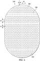
- Figure 3is a top view of the dressing 110 in the example of Figure 2 , as assembled, illustrating additional details that may be associated with some embodiments.
- the cover 125 and the third layer 215may have substantially the same perimeter shape and dimensions, so that the cover 125 and the third layer 215 are coextensive in some examples.
- the cover 125may be substantially transparent, allowing visibility of the apertures 235 in some embodiments.
- the first layer 205may be centrally disposed over the third layer 215, such as over the treatment aperture 230 (not visible in Figure 3 ).
- the cover 125may be disposed over the first layer 205 and coupled to the third layer 215 around the first layer 205 so that at least some of the adhesive 255 can be disposed adjacent to the apertures 235.
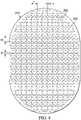
- Figure 4is a bottom view of the dressing 110 in the example of Figure 2 , as assembled, illustrating additional details that may be associated with some embodiments.
- a substantial number of the fluid restrictions 220may be aligned or otherwise exposed through the treatment aperture 230, and at least some portion of the first layer 205 may be disposed adjacent to the fluid restrictions 220 opposite the treatment aperture 230.
- the first layer 205 and the second layer 210may be substantially aligned with the treatment aperture 230, or may extend across the treatment aperture 230.
- the first layer 205may have a first edge 405, and the second layer 210 may have a second edge 410.
- the first edge 405 and the second edge 410may have substantially the same shape so that adjacent faces of the first layer 205 and the second layer 210 are geometrically similar.
- the first edge 405 and the second edge 410may also be congruent in some examples, so that adjacent faces of the first layer 205 and the second layer 210 are substantially coextensive and have substantially the same surface area.
- the first edge 405defines a larger face of the first layer 205 than the face of the second layer 210 defined by the second edge 410, and the larger face of the first layer 205 extends past the smaller face of the second edge 410.
- the faces defined by the first edge 405, the second edge 410, or bothmay also be geometrically similar to the treatment aperture 230 in some embodiments, as illustrated in the example of Figure 4 , and may be larger than the treatment aperture 230.
- the third layer 215may have an overlay margin 415 around the treatment aperture 230, which may have an additional adhesive disposed therein.
- the treatment aperture 230may be an ellipse or a stadium in some embodiments.
- the treatment aperture 230may have an area that is equal to about 20% to about 80% of the area of the third layer 215 in some examples.
- the treatment aperture 230may also have an area that is equal to about 20% to about 80% of the area of a face of defined by the first edge 405 of the first layer 205.
- a width of about 90 millimeters to about 110 millimeters and a length of about 150 millimeters to about 160 millimetersmay be suitable for some embodiments of the treatment aperture 230.
- the width of the treatment aperture 230may be about 100 millimeters, and the length may be about 155 millimeters.
- a suitable width for the overlay margin 415may be about 2 millimeters to about 3 millimeters.
- the overlay margin 415may be coextensive with an area defined between the treatment aperture 230 and the first edge 405, and the adhesive may secure the first layer 205, the second layer 210, or both to the third layer 215.
- Figure 5is an assembly view of another example of the dressing 110 of Figure 1 , illustrating additional details that may be associated with some embodiments. As illustrated in Figure 5 , some examples of the third layer 215 may not have the treatment aperture 230, and the apertures 235 may be distributed in a uniform pattern across the third layer 215.
- Figure 6is a schematic view of an example of the second layer 210, illustrating additional details that may be associated with some embodiments.
- the fluid restrictions 220may each consist essentially of one or more slits having a length L. A length of about 3 millimeters may be particularly suitable for some embodiments.
- Figure 6additionally illustrates an example of a uniform distribution pattern of the fluid restrictions 220.
- the fluid restrictions 220are substantially coextensive with the second layer 210, and are distributed across the second layer 210 in a grid of parallel rows and columns, in which the slits are also mutually parallel to each other. In some embodiments, the rows may be spaced a distance D1.
- a distance of about 3 millimeters on centermay be suitable for some embodiments.
- the fluid restrictions 220 within each of the rowsmay be spaced a distance D2, which may be about 3 millimeters on center in some examples.
- the fluid restrictions 220 in adjacent rowsmay be aligned or offset in some embodiments. For example, adjacent rows may be offset, as illustrated in Figure 6 , so that the fluid restrictions 220 are aligned in alternating rows and separated by a distance D3, which may be about 6 millimeters in some embodiments.
- the spacing of the fluid restrictions 220may vary in some embodiments to increase the density of the fluid restrictions 220 according to therapeutic requirements.
- Figure 7is a schematic view of an example configuration of the apertures 235, illustrating additional details that may be associated with some embodiments of the third layer 215.
- the apertures 420are generally circular and have a diameter D4, which may be about 6 millimeters to about 8 millimeters in some embodiments. A diameter D4 of about 7 millimeters may be particularly suitable for some embodiments.
- Figure 7also illustrates an example of a uniform distribution pattern of the apertures 235.
- the apertures 235are distributed across the third layer 215 in a grid of parallel rows and columns. Within each row and column, the apertures 235 may be equidistant from each other, as illustrated in the example of Figure 7.
- Figure 7illustrates one example configuration that may be particularly suitable for many applications, in which the apertures 235 are spaced a distance D5 apart along each row and column, with an offset of D6.
- the distance D5may be about 9 millimeters to about 10 millimeters
- the offset D6may be about 8 millimeters to about 9 millimeters.
- Figure 8is a schematic view of the apertures 235 in the example of Figure 7 overlaid on the second layer 210 of Figure 6 , illustrating additional details that may be associated with some example embodiments of the tissue interface 120.
- more than one of the fluid restrictions 220may be aligned, overlapping, in registration with, or otherwise fluidly coupled to the apertures 235 in some embodiments.
- one or more of the fluid restrictions 220may be only partially registered with the apertures 235.
- the apertures 235 in the example of Figure 8are generally sized and configured so that at least four of the fluid restrictions 220 is registered with each one of the apertures 235.
- one or more of the fluid restrictions 220may be registered with more than one of the apertures 235.
- any one or more of the fluid restrictions 220may be a perforation or a fenestration that extends across two or more of the apertures 235. Additionally or alternatively, one or more of the fluid restrictions 220 may not be registered with any of the apertures 235.
- the apertures 235may be sized to expose a portion of the second layer 210, the fluid restrictions 220, or both through the third layer 215.
- the apertures 235 in the example of Figure 8are generally sized to expose more than one of the fluid restrictions 220. Some or all of the apertures 235 may be sized to expose two or three of the fluid restrictions 220.
- the length of each of the fluid restrictions 220may be substantially smaller than the diameter of each of the apertures 235. More generally, the average dimensions of the fluid restrictions 220 are substantially smaller than the average dimensions of the apertures 235.
- the apertures 235may be elliptical, and the length of each of the fluid restrictions 220 may be substantially smaller than the major axis or the minor axis. In some embodiments, though, the dimensions of the fluid restrictions 220 may exceed the dimensions of the apertures 235, and the size of the apertures 235 may limit the effective size of the fluid restrictions 220 exposed to the lower surface of the dressing 110.
- Individual components of the dressing 110 in the examples of Figures 2-8may be bonded or otherwise secured to one another with a solvent or non-solvent adhesive, or with thermal welding, for example, without adversely affecting fluid management.
- the second layer 210 or the first layer 205may be coupled to the interior border 250 or the overlay margin 415 of the third layer 215 in any suitable manner, such as with a weld or an adhesive, for example.
- the cover 125, the first layer 205, the second layer 210, the third layer 215, or various combinationsmay be assembled before application or in situ.
- the second layer 210may be laminated to the first layer 205 in some embodiments.
- the cover 125may be disposed over the first layer 205 and coupled to the third layer 215 around the first layer 205 in some embodiments.
- one or more layers of the tissue interface 120may be coextensive.
- the second layer 210may be cut flush with the edge of the first layer 205.
- the dressing 110may be provided as a single, composite dressing.
- the third layer 215may be coupled to the cover 125 to enclose the first layer 205 and the second layer 210, wherein the third layer 215 may be configured to face a tissue site.
- the release liner 260(if included) may be removed to expose the third layer 215, which can provide a lower surface of the dressing 110 to be placed within, over, on, or otherwise proximate to a tissue site, particularly a surface tissue site and adjacent epidermis.
- the second layer 210, the third layer 215, or bothmay be interposed between the first layer 205 and the tissue site, which can substantially reduce or eliminate adverse interaction between the first layer 205 and the tissue site.
- the third layer 215may be placed over a surface wound (including edges of the wound) and undamaged epidermis to prevent direct contact with the first layer 205.
- the treatment aperture 230 of the third layer 215may be positioned adjacent to, proximate to, or covering a tissue site.
- the second layer 210, the fluid restrictions 220, or bothmay be exposed to a tissue site through the treatment aperture 230, the apertures 235, or both.
- the periphery 225 of the third layer 215may be positioned adjacent to or proximate to tissue around or surrounding the tissue site.
- the third layer 215may be sufficiently tacky to hold the dressing 110 in position, while also allowing the dressing 110 to be removed or re-positioned without trauma to the tissue site.
- Removing the release liner 260can also expose the adhesive 255, and the cover 125 may be attached to an attachment surface, such as the periphery 225 or other area around the treatment aperture 235 and the first layer 205.
- the adhesive 255may also be attached to epidermis peripheral to a tissue site, around the first layer 205 and the second layer 210.
- the adhesive 255may be in fluid communication with an attachment surface through the apertures 235 in at least the periphery 225 of the third layer 215.
- the adhesive 255may also be in fluid communication with the edges 245 through the apertures 235 exposed at the edges 245.
- the adhesive 255may be pressed through the apertures 235 to bond the dressing 110 to the attachment surface.
- the apertures 235 at the edges 245may permit the adhesive 255 to flow around the edges 245 for enhancing the adhesion of the edges 245 to an attachment surface.
- the apertures 235may be sized to control the amount of the adhesive 255 exposed through the apertures 235.
- the relative sizes of the apertures 235may be configured to maximize the surface area of the adhesive 255 exposed and in fluid communication through the apertures 235 at the corners 240.
- the edges 245may intersect at substantially a right angle, or about 90 degrees, to define the corners 240.
- the corners 240may have a radius of about 10 millimeters.
- three of the apertures 235may be positioned in a triangular configuration at the corners 240 to maximize the exposed surface area for the adhesive 255.
- the size and number of the apertures 235 in the corners 240may be adjusted as necessary, depending on the chosen geometry of the corners 240, to maximize the exposed surface area of the adhesive 255.
- the apertures 235 at the corners 240may be fully contained within the third layer 215, substantially precluding fluid communication in a lateral direction exterior to the corners 240.
- the apertures 235 at the corners 240 being fully contained within the third layer 215may substantially preclude fluid communication of the adhesive 255 exterior to the corners 240, and may provide improved handling of the dressing 110 during deployment at a tissue site.
- the exterior of the corners 240 being substantially free of the adhesive 255may increase the flexibility of the corners 240 to enhance comfort.
- the bond strength of the adhesive 255may vary based on the configuration of the third layer 215.
- the bond strengthmay vary based on the size of the apertures 235.
- the bond strengthmay be inversely proportional to the size of the apertures 235.
- the bond strengthmay vary in different locations, for example, if the size of the apertures 235 varies. For example, a lower bond strength in combination with larger apertures 235 may provide a bond comparable to a higher bond strength in locations having smaller apertures 235.
- the geometry and dimensions of the tissue interface 120, the cover 125, or bothmay vary to suit a particular application or anatomy.
- the geometry or dimensions of the tissue interface 120 and the cover 125may be adapted to provide an effective and reliable seal against challenging anatomical surfaces, such as an elbow or heel, at and around a tissue site.
- the dimensionsmay be modified to increase the surface area for the third layer 215 to enhance the movement and proliferation of epithelial cells at a tissue site and reduce the likelihood of granulation tissue in-growth.
- the dressing 110can provide a sealed therapeutic environment proximate to a tissue site, substantially isolated from the external environment, and the negative-pressure source 105 can reduce the pressure in the sealed therapeutic environment.
- the treatment aperture 230can provide an open area for delivery of negative pressure and passage of wound fluid through the second layer 210 and the first layer 205.
- the third layer 215may provide an effective and reliable seal against challenging anatomical surfaces, such as an elbow or heel, at and around a tissue site.
- the dressing 110may permit re-application or re-positioning, to correct air leaks caused by creases and other discontinuities in the dressing 110, for example. The ability to rectify leaks may increase the efficacy of the therapy and reduce power consumption in some embodiments.
- the dressing interface 270may be disposed over the aperture 275 and attached to the cover 125.
- the fluid conductor 265may be fluidly coupled to the dressing interface 270 and to the negative-pressure source 105.
- Negative pressure applied through the tissue interface 120can create a negative pressure differential across the fluid restrictions 220 in the second layer 210, which can open or expand the fluid restrictions 220.
- the fluid restrictions 220may comprise substantially closed fenestrations through the second layer 210
- a pressure gradient across the fenestrationscan strain the adjacent material of the second layer 210 and increase the dimensions of the fenestrations to allow liquid movement through them, similar to the operation of a duckbill valve.
- Opening the fluid restrictions 220can allow exudate and other liquid movement through the fluid restrictions 220 into the first layer 205.
- the first layer 205can provide passage of negative pressure and wound fluid, which can be collected in the container 115.
- Changes in pressurecan also cause the first layer 205 to expand and contract, and the second layer 210, the third layer 215, or both may protect the epidermis from irritation that could be caused by expansion, contraction, or other movement of the first layer 205.
- the overlay margin 415may be disposed between the first layer 205 and epidermis around a tissue site.
- the second layer 210 and the third layer 215can also substantially reduce or prevent exposure of a tissue site to the first layer 205, which can inhibit growth of tissue into the first layer 205.
- the second layer 210may cover the treatment aperture 230 to prevent direct contact between the first layer 205 and a tissue site.
- the pressure differential across the fluid restrictions 220can dissipate, allowing the fluid restrictions 220 to close and prevent exudate or other liquid from returning to the tissue site through the second layer 210.
- a fillermay also be disposed between a tissue site and the third layer 215.
- a tissue siteis a surface wound
- a wound fillermay be applied interior to the periwound
- the third layer 215may be disposed over the periwound and the wound filler.
- the fillermay be a manifold, such as an open-cell foam.
- the fillermay comprise or consist essentially of the same material as the first layer 205 in some embodiments.
- instillation solution or other fluidmay be distributed to the dressing 110, which can increase the pressure in the tissue interface 120.
- the increased pressure in the tissue interface 120can create a positive pressure differential across the fluid restrictions 220 in the second layer 210, which can open the fluid restrictions 220 to allow the instillation solution or other fluid to be distributed to the tissue site.
- the dressing described hereinmay provide significant advantages. For example, some dressings for negative-pressure therapy can require time and skill to be properly sized and applied to achieve a good fit and seal. In contrast, some embodiments of the dressing 110 provide a negative-pressure dressing that is simple to apply, reducing the time to apply and remove. In some embodiments, for example, the dressing 110 may be a fully-integrated negative-pressure therapy dressing that can be applied to a tissue site (including on the periwound) in one step, without being cut to size, while still providing or improving many benefits of other negative-pressure therapy dressings that require sizing.
- Such benefitsmay include good manifolding, beneficial granulation, protection of the peripheral tissue from maceration, protection of the tissue site from shedding materials, and a low-trauma and high-seal bond. These characteristics may be particularly advantageous for surface wounds having moderate depth and medium-to-high levels of exudate.
- Some embodiments of the dressing 110may remain on the tissue site for at least 5 days, and some embodiments may remain for at least 7 days.
- Antimicrobial agents in the dressing 110may extend the usable life of the dressing 110 by reducing or eliminating infection risks that may be associated with extended use, particularly use with infected or highly exuding wounds.
Landscapes
- Health & Medical Sciences (AREA)
- Engineering & Computer Science (AREA)
- Life Sciences & Earth Sciences (AREA)
- Veterinary Medicine (AREA)
- Animal Behavior & Ethology (AREA)
- General Health & Medical Sciences (AREA)
- Public Health (AREA)
- Heart & Thoracic Surgery (AREA)
- Biomedical Technology (AREA)
- Vascular Medicine (AREA)
- Chemical & Material Sciences (AREA)
- Hematology (AREA)
- Materials Engineering (AREA)
- Epidemiology (AREA)
- Surgery (AREA)
- Anesthesiology (AREA)
- Chemical Kinetics & Catalysis (AREA)
- Dermatology (AREA)
- Manufacturing & Machinery (AREA)
- Mechanical Engineering (AREA)
- Medical Informatics (AREA)
- Molecular Biology (AREA)
- Dispersion Chemistry (AREA)
- Medicinal Chemistry (AREA)
- Media Introduction/Drainage Providing Device (AREA)
- Materials For Medical Uses (AREA)
- Treatments For Attaching Organic Compounds To Fibrous Goods (AREA)
Description
- The invention set forth in the appended claims relates generally to dressings for tissue treatment with negative pressure.
- Clinical studies and practice have shown that reducing pressure in proximity to a tissue site can augment and accelerate growth of new tissue at the tissue site. The applications of this phenomenon are numerous, but it has proven particularly advantageous for treating wounds. Regardless of the etiology of a wound, whether trauma, surgery, or another cause, proper care of the wound is important to the outcome. Treatment of wounds or other tissue with reduced pressure may be commonly referred to as "negative-pressure therapy," but is also known by other names, including "negative-pressure wound therapy," "reduced-pressure therapy," "vacuum therapy," "vacuum-assisted closure," and "topical negative-pressure," for example. Negative-pressure therapy may provide a number of benefits, including migration of epithelial and subcutaneous tissues, improved blood flow, and micro-deformation of tissue at a wound site. Together, these benefits can increase development of granulation tissue and reduce healing times.
- There is also widespread acceptance that cleansing a tissue site can be highly beneficial for new tissue growth. For example, a wound or a cavity can be washed out with a liquid solution for therapeutic purposes. These practices are commonly referred to as "irrigation" and "lavage" respectively. "Instillation" is another practice that generally refers to a process of slowly introducing fluid to a tissue site and leaving the fluid for a prescribed period of time before removing the fluid. For example, instillation of topical treatment solutions over a wound bed can be combined with negative-pressure therapy to further promote wound healing by loosening soluble contaminants in a wound bed and removing infectious material. As a result, soluble bacterial burden can be decreased, contaminants removed, and the wound cleansed.
- While the clinical benefits of negative-pressure therapy and/or instillation therapy are widely known, improvements to therapy systems, components, and processes may benefit healthcare providers and patients.
- The invention relates to a dressing for treating a tissue site with negative pressure may comprise a sealing layer having a treatment aperture and a plurality of perforations around the treatment aperture, and a fluid control layer having a plurality of fluid restrictions aligned with the treatment aperture. A manifold 2- is disposed adjacent to the fluid restrictions, and a cover comprising a non-porous film is disposed over the manifold and coupled to the sealing layer around the manifold. The cover may additionally have a pressure-sensitive adhesive disposed adjacent to the plurality of perforations. In more particular embodiments, the fluid control layer may comprise or consist essentially of a polyurethane film. The sealing layer may be formed from a gel, such as a silicone gel in some embodiments.
- Objectives, advantages, and a preferred mode of making and using the claimed subject matter may be understood best by reference to the accompanying drawings in conjunction with the following detailed description of illustrative embodiments.
Figure 1 is a functional block diagram of an example embodiment of a therapy system that can provide negative-pressure treatment and instillation treatment in accordance with this specification;Figure 2 is an assembly view of an example of a dressing, illustrating additional details that may be associated with some example embodiments of the therapy system ofFigure 1 ;Figure 3 is a top view of the example dressing ofFigure 2 ;Figure 4 is a bottom view of the example dressing ofFigure 2 ;Figure 5 is an assembly view of another example of a dressing, illustrating additional details that may be associated with some example embodiment of the therapy system ofFigure 1 ;Figure 6 is a schematic view of an example configuration of fluid restrictions in a layer that may be associated with some embodiments of the dressing ofFigure 2 orFigure 5 ;Figure 7 is a schematic view of an example configuration of apertures in a layer that may be associated with some embodiments of the dressing ofFigure 5 ; andFigure 8 is a schematic view of the example layer ofFigure 6 overlaid on the example layer ofFigure 7 .- The following description of example embodiments provides information that enables a person skilled in the art to make and use the subject matter set forth in the appended claims, but it may omit certain details already well-known in the art. The following detailed description is, therefore, to be taken as illustrative and not limiting.
- The example embodiments may also be described herein with reference to spatial relationships between various elements or to the spatial orientation of various elements depicted in the attached drawings. In general, such relationships or orientation assume a frame of reference consistent with or relative to a patient in a position to receive treatment. However, as should be recognized by those skilled in the art, this frame of reference is merely a descriptive expedient rather than a strict prescription.
Figure 1 is a simplified functional block diagram of an example embodiment of atherapy system 100 that can provide negative-pressure therapy with instillation of topical treatment solutions to a tissue site in accordance with this specification.- The term "tissue site" in this context broadly refers to a wound, defect, or other treatment target located on or within tissue, including, but not limited to, bone tissue, adipose tissue, muscle tissue, neural tissue, dermal tissue, vascular tissue, connective tissue, cartilage, tendons, or ligaments. A wound may include chronic, acute, traumatic, subacute, and dehisced wounds, partial-thickness burns, ulcers (such as diabetic, pressure, or venous insufficiency ulcers), flaps, and grafts, for example. The term "tissue site" may also refer to areas of any tissue that are not necessarily wounded or defective, but are instead areas in which it may be desirable to add or promote the growth of additional tissue. For example, negative pressure may be applied to a tissue site to grow additional tissue that may be harvested and transplanted.
- The
therapy system 100 may include a source or supply of negative pressure, such as a negative-pressure source 105, and one or more distribution components. A distribution component is preferably detachable and may be disposable, reusable, or recyclable. A dressing, such as adressing 110, and a fluid container, such as acontainer 115, are examples of distribution components that may be associated with some examples of thetherapy system 100. As illustrated in the example ofFigure 1 , thedressing 110 may comprise or consist essentially of atissue interface 120, acover 125, or both in some embodiments. - A fluid conductor is another illustrative example of a distribution component. A "fluid conductor," in this context, broadly includes a tube, pipe, hose, conduit, or other structure with one or more lumina or open pathways adapted to convey a fluid between two ends. Typically, a tube is an elongated, cylindrical structure with some flexibility, but the geometry and rigidity may vary. Moreover, some fluid conductors may be molded into or otherwise integrally combined with other components. Distribution components may also include or comprise interfaces or fluid ports to facilitate coupling and de-coupling other components. In some embodiments, for example, a dressing interface may facilitate coupling a fluid conductor to the
dressing 110. For example, such a dressing interface may be a SENSAT.R.A.C.™ Pad available from Kinetic Concepts, Inc. of San Antonio, Texas. - The
therapy system 100 may also include a regulator or controller, such as acontroller 130. Additionally, thetherapy system 100 may include sensors to measure operating parameters and provide feedback signals to thecontroller 130 indicative of the operating parameters. As illustrated inFigure 1 , for example, thetherapy system 100 may include afirst sensor 135 and asecond sensor 140 coupled to thecontroller 130. - The
therapy system 100 may also include a source of instillation solution. For example, asolution source 145 may be fluidly coupled to thedressing 110, as illustrated in the example embodiment ofFigure 1 . Thesolution source 145 may be fluidly coupled to a positive-pressure source such as a positive-pressure source 150, a negative-pressure source such as the negative-pressure source 105, or both in some embodiments. A regulator, such as aninstillation regulator 155, may also be fluidly coupled to thesolution source 145 and thedressing 110 to ensure proper dosage of instillation solution (e.g. saline) to a tissue site. For example, theinstillation regulator 155 may comprise a piston that can be pneumatically actuated by the negative-pressure source 105 to draw instillation solution from the solution source during a negative-pressure interval and to instill the solution to a dressing during a venting interval. Additionally or alternatively, thecontroller 130 may be coupled to the negative-pressure source 105, the positive-pressure source 150, or both, to control dosage of instillation solution to a tissue site. In some embodiments, theinstillation regulator 155 may also be fluidly coupled to the negative-pressure source 105 through thedressing 110, as illustrated in the example ofFigure 1 . - Some components of the
therapy system 100 may be housed within or used in conjunction with other components, such as sensors, processing units, alarm indicators, memory, databases, software, display devices, or user interfaces that further facilitate therapy. For example, in some embodiments, the negative-pressure source 105 may be combined with thecontroller 130, thesolution source 145, and other components into a therapy unit. - In general, components of the
therapy system 100 may be coupled directly or indirectly. For example, the negative-pressure source 105 may be directly coupled to thecontainer 115 and may be indirectly coupled to the dressing 110 through thecontainer 115. Coupling may include fluid, mechanical, thermal, electrical, or chemical coupling (such as a chemical bond), or some combination of coupling in some contexts. For example, the negative-pressure source 105 may be electrically coupled to thecontroller 130 and may be fluidly coupled to one or more distribution components to provide a fluid path to a tissue site. In some embodiments, components may also be coupled by virtue of physical proximity, being integral to a single structure, or being formed from the same piece of material. - A negative-pressure supply, such as the negative-
pressure source 105, may be a reservoir of air at a negative pressure or may be a manual or electrically-powered device, such as a vacuum pump, a suction pump, a wall suction port available at many healthcare facilities, or a micro-pump, for example. "Negative pressure" generally refers to a pressure less than a local ambient pressure, such as the ambient pressure in a local environment external to a sealed therapeutic environment. In many cases, the local ambient pressure may also be the atmospheric pressure at which a tissue site is located. Alternatively, the pressure may be less than a hydrostatic pressure associated with tissue at the tissue site. Unless otherwise indicated, values of pressure stated herein are gauge pressures. References to increases in negative pressure typically refer to a decrease in absolute pressure, while decreases in negative pressure typically refer to an increase in absolute pressure. While the amount and nature of negative pressure provided by the negative-pressure source 105 may vary according to therapeutic requirements, the pressure is generally a low vacuum, also commonly referred to as a rough vacuum, between -5 mm Hg (-667 Pa) and -500 mm Hg (-66.7 kPa). Common therapeutic ranges are between -50 mm Hg (-6.7 kPa) and -300 mm Hg (-39.9 kPa). - The
container 115 is representative of a container, canister, pouch, or other storage component, which can be used to manage exudates and other fluids withdrawn from a tissue site. In many environments, a rigid container may be preferred or required for collecting, storing, and disposing of fluids. In other environments, fluids may be properly disposed of without rigid container storage, and a re-usable container could reduce waste and costs associated with negative-pressure therapy. - A controller, such as the
controller 130, may be a microprocessor or computer programmed to operate one or more components of thetherapy system 100, such as the negative-pressure source 105. In some embodiments, for example, thecontroller 130 may be a microcontroller, which generally comprises an integrated circuit containing a processor core and a memory programmed to directly or indirectly control one or more operating parameters of thetherapy system 100. Operating parameters may include the power applied to the negative-pressure source 105, the pressure generated by the negative-pressure source 105, or the pressure distributed to thetissue interface 120, for example. Thecontroller 130 is also preferably configured to receive one or more input signals, such as a feedback signal, and programmed to modify one or more operating parameters based on the input signals. - Sensors, such as the
first sensor 135 and thesecond sensor 140, are generally known in the art as any apparatus operable to detect or measure a physical phenomenon or property, and generally provide a signal indicative of the phenomenon or property that is detected or measured. For example, thefirst sensor 135 and thesecond sensor 140 may be configured to measure one or more operating parameters of thetherapy system 100. In some embodiments, thefirst sensor 135 may be a transducer configured to measure pressure in a pneumatic pathway and convert the measurement to a signal indicative of the pressure measured. In some embodiments, for example, thefirst sensor 135 may be a piezo-resistive strain gauge. Thesecond sensor 140 may optionally measure operating parameters of the negative-pressure source 105, such as a voltage or current, in some embodiments. Preferably, the signals from thefirst sensor 135 and thesecond sensor 140 are suitable as an input signal to thecontroller 130, but some signal conditioning may be appropriate in some embodiments. For example, the signal may need to be filtered or amplified before it can be processed by thecontroller 130. Typically, the signal is an electrical signal, but may be represented in other forms, such as an optical signal. - The
tissue interface 120 can be generally adapted to partially or fully contact a tissue site. Thetissue interface 120 may take many forms, and may have many sizes, shapes, or thicknesses, depending on a variety of factors, such as the type of treatment being implemented or the nature and size of a tissue site. For example, the size and shape of thetissue interface 120 may be adapted to the contours of deep and irregular shaped tissue sites. Any or all of the surfaces of thetissue interface 120 may have an uneven, coarse, or jagged profile. - In some embodiments, the
tissue interface 120 may comprise or consist essentially of a manifold. A manifold in this context may comprise or consist essentially of a means for collecting or distributing fluid across thetissue interface 120 under pressure. For example, a manifold may be adapted to receive negative pressure from a source and distribute negative pressure through multiple apertures across thetissue interface 120, which may have the effect of collecting fluid from across a tissue site and drawing the fluid toward the source. In some embodiments, the fluid path may be reversed or a secondary fluid path may be provided to facilitate delivering fluid, such as fluid from a source of instillation solution, across a tissue site. - In some embodiments, the
cover 125 may provide a bacterial barrier and protection from physical trauma. Thecover 125 may also be constructed from a material that can reduce evaporative losses and provide a fluid seal between two components or two environments, such as between a therapeutic environment and a local external environment. Thecover 125 may comprise or consist of, for example, an elastomeric film or membrane that can provide a seal adequate to maintain a negative pressure at a tissue site for a given negative-pressure source. Thecover 125 may have a high moisture-vapor transmission rate (MVTR) in some applications. For example, the MVTR may be at least 250 grams per square meter per twenty-four hours in some embodiments, measured using an upright cup technique according to ASTM E96/E96M Upright Cup Method at 38°C and 10% relative humidity (RH). In some embodiments, an MVTR up to 5,000 grams per square meter per twenty-four hours may provide effective breathability and mechanical properties. - In some example embodiments, the
cover 125 may be a non-porous polymer drape or film, such as a polyurethane film, that is permeable to water vapor but impermeable to liquid. Such drapes typically have a thickness in the range of 25-50 microns. For permeable materials, the permeability generally should be low enough that a desired negative pressure may be maintained. Thecover 125 may comprise, for example, one or more of the following materials: polyurethane (PU), such as hydrophilic polyurethane; cellulosics; hydrophilic polyamides; polyvinyl alcohol; polyvinyl pyrrolidone; hydrophilic acrylics; silicones, such as hydrophilic silicone elastomers; natural rubbers; polyisoprene; styrene butadiene rubber; chloroprene rubber; polybutadiene; nitrile rubber; butyl rubber; ethylene propylene rubber; ethylene propylene diene monomer; chlorosulfonated polyethylene; polysulfide rubber; ethylene vinyl acetate (EVA); co-polyester; and polyether block polymide copolymers. Such materials are commercially available as, for example, Tegaderm® drape, commercially available from 3M Company, Minneapolis Minnesota; polyurethane (PU) drape, commercially available from Avery Dennison Corporation, Pasadena, California; polyether block polyamide copolymer (PEBAX), for example, from Arkema S.A., Colombes, France; and Inspire 2301 and Inpsire 2327 polyurethane films, commercially available from Expopack Advanced Coatings, Wrexham, United Kingdom. In some embodiments, thecover 125 may comprise INSPIRE 2301 having an MVTR (upright cup technique) of 2600 g/m2/24 hours and a thickness of about 30 microns. - An attachment device may be used to attach the
cover 125 to an attachment surface, such as undamaged epidermis, a gasket, or another cover. The attachment device may take many forms. For example, an attachment device may be a medically-acceptable, pressure-sensitive adhesive configured to bond thecover 125 to epidermis around a tissue site. In some embodiments, for example, some or all of thecover 125 may be coated with an adhesive, such as an acrylic adhesive, which may have a coating weight of about 25-65 grams per square meter (g.s.m.). Thicker adhesives, or combinations of adhesives, may be applied in some embodiments to improve the seal and reduce leaks. Other example embodiments of an attachment device may include a double-sided tape, paste, hydrocolloid, hydrogel, silicone gel, or organogel. - The
solution source 145 may also be representative of a container, canister, pouch, bag, or other storage component, which can provide a solution for instillation therapy. Compositions of solutions may vary according to a prescribed therapy, but examples of solutions that may be suitable for some prescriptions include hypochlorite-based solutions, silver nitrate (0.5%), sulfur-based solutions, biguanides, cationic solutions, and isotonic solutions. - In operation, the
tissue interface 120 may be placed within, over, on, or otherwise proximate to a tissue site. If the tissue site is a wound, for example, thetissue interface 120 may partially or completely fill the wound, or it may be placed over the wound. Thecover 125 may be placed over thetissue interface 120 and sealed to an attachment surface near a tissue site. For example, thecover 125 may be sealed to undamaged epidermis peripheral to a tissue site. Thus, the dressing 110 can provide a sealed therapeutic environment proximate to a tissue site, substantially isolated from the external environment, and the negative-pressure source 105 can reduce pressure in the sealed therapeutic environment. - The fluid mechanics of using a negative-pressure source to reduce pressure in another component or location, such as within a sealed therapeutic environment, can be mathematically complex. However, the basic principles of fluid mechanics applicable to negative-pressure therapy and instillation are generally well-known to those skilled in the art, and the process of reducing pressure may be described illustratively herein as "delivering," "distributing," or "generating" negative pressure, for example.
- In general, exudate and other fluid flow toward lower pressure along a fluid path. Thus, the term "downstream" typically implies something in a fluid path relatively closer to a source of negative pressure or further away from a source of positive pressure. Conversely, the term "upstream" implies something relatively further away from a source of negative pressure or closer to a source of positive pressure. Similarly, it may be convenient to describe certain features in terms of fluid "inlet" or "outlet" in such a frame of reference. This orientation is generally presumed for purposes of describing various features and components herein. However, the fluid path may also be reversed in some applications, such as by substituting a positive-pressure source for a negative-pressure source, and this descriptive convention should not be construed as a limiting convention.
- Negative pressure applied across the tissue site through the
tissue interface 120 in the sealed therapeutic environment can induce macro-strain and micro-strain in the tissue site. Negative pressure can also remove exudate and other fluid from a tissue site, which can be collected incontainer 115. - In some embodiments, the
controller 130 may receive and process data from one or more sensors, such as thefirst sensor 135. Thecontroller 130 may also control the operation of one or more components of thetherapy system 100 to manage the pressure delivered to thetissue interface 120. In some embodiments,controller 130 may include an input for receiving a desired target pressure and may be programmed for processing data relating to the setting and inputting of the target pressure to be applied to thetissue interface 120. In some example embodiments, the target pressure may be a fixed pressure value set by an operator as the target negative pressure desired for therapy at a tissue site and then provided as input to thecontroller 130. The target pressure may vary from tissue site to tissue site based on the type of tissue forming a tissue site, the type of injury or wound (if any), the medical condition of the patient, and the preference of the attending physician. After selecting a desired target pressure, thecontroller 130 can operate the negative-pressure source 105 in one or more control modes based on the target pressure and may receive feedback from one or more sensors to maintain the target pressure at thetissue interface 120. - In some embodiments, the
controller 130 may have a continuous pressure mode, in which the negative-pressure source 105 is operated to provide a constant target negative pressure for the duration of treatment or until manually deactivated. Additionally or alternatively, the controller may have an intermittent pressure mode. For example, thecontroller 130 can operate the negative-pressure source 105 to cycle between a target pressure and atmospheric pressure. For example, the target pressure may be set at a value of 135 mmHg for a specified period of time (e.g., 5 min), followed by a specified period of time (e.g., 2 min) of deactivation. The cycle can be repeated by activating the negative-pressure source 105, which can form a square wave pattern between the target pressure and atmospheric pressure. - In some example embodiments, the increase in negative-pressure from ambient pressure to the target pressure may not be instantaneous. For example, the negative-
pressure source 105 and the dressing 110 may have an initial rise time. The initial rise time may vary depending on the type of dressing and therapy equipment being used. For example, the initial rise time for one therapy system may be in a range of about 20-30 mmHg/second and in a range of about 5-10 mmHg/second for another therapy system. If thetherapy system 100 is operating in an intermittent mode, the repeating rise time may be a value substantially equal to the initial rise time. - In some example dynamic pressure control modes, the target pressure can vary with time. For example, the target pressure may vary in the form of a triangular waveform, varying between a negative pressure of 50 and 135 mmHg with a rise time set at a rate of +25 mmHg/min. and a descent time set at -25 mmHg/min. In other embodiments of the
therapy system 100, the triangular waveform may vary between negative pressure of 25 and 135 mmHg with a rise time set at a rate of +30 mmHg/min and a descent time set at -30 mmHg/min. - In some embodiments, the
controller 130 may control or determine a variable target pressure in a dynamic pressure mode, and the variable target pressure may vary between a maximum and minimum pressure value that may be set as an input prescribed by an operator as the range of desired negative pressure. The variable target pressure may also be processed and controlled by thecontroller 130, which can vary the target pressure according to a predetermined waveform, such as a triangular waveform, a sine waveform, or a saw-tooth waveform. In some embodiments, the waveform may be set by an operator as the predetermined or time-varying negative pressure desired for therapy. - In some embodiments, the
controller 130 may receive and process data, such as data related to instillation solution provided to thetissue interface 120. Such data may include the type of instillation solution prescribed by a clinician, the volume of fluid or solution to be instilled to a tissue site ("fill volume"), and the amount of time prescribed for leaving solution at a tissue site ("dwell time") before applying a negative pressure to the tissue site. The fill volume may be, for example, between 10 and 500 mL, and the dwell time may be between one second to 30 minutes. Thecontroller 130 may also control the operation of one or more components of thetherapy system 100 to instill solution. For example, thecontroller 130 may manage fluid distributed from thesolution source 145 to thetissue interface 120. In some embodiments, fluid may be instilled to a tissue site by applying a negative pressure from the negative-pressure source 105 to reduce the pressure at the tissue site, drawing solution into thetissue interface 120. In some embodiments, solution may be instilled to a tissue site by applying a positive pressure from the positive-pressure source 160 to move solution from thesolution source 145 to thetissue interface 120. Additionally or alternatively, thesolution source 145 may be elevated to a height sufficient to allow gravity to move solution into thetissue interface 120. - The
controller 130 may also control the fluid dynamics of instillation by providing a continuous flow of solution or an intermittent flow of solution. Negative pressure may be applied to provide either continuous flow or intermittent flow of solution. The application of negative pressure may be implemented to provide a continuous pressure mode of operation to achieve a continuous flow rate of instillation solution through thetissue interface 120, or it may be implemented to provide a dynamic pressure mode of operation to vary the flow rate of instillation solution through thetissue interface 120. Alternatively, the application of negative pressure may be implemented to provide an intermittent mode of operation to allow instillation solution to dwell at thetissue interface 120. In an intermittent mode, a specific fill volume and dwell time may be provided depending, for example, on the type of tissue site being treated and the type of dressing being utilized. After or during instillation of solution, negative-pressure treatment may be applied. Thecontroller 130 may be utilized to select a mode of operation and the duration of the negative pressure treatment before commencing another instillation cycle. Figure 2 is an assembly view of an example of the dressing 110 ofFigure 1 , illustrating additional details that may be associated with some embodiments in which thetissue interface 120 comprises more than one layer. In the example ofFigure 2 , thetissue interface 120 comprises afirst layer 205, asecond layer 210, and athird layer 215. In some embodiments, thefirst layer 205 may be disposed adjacent to thesecond layer 210, and thethird layer 215 may also be disposed adjacent to thesecond layer 210 opposite thefirst layer 205. For example, thefirst layer 205 and thesecond layer 210 may be stacked so that thefirst layer 205 is in contact with thesecond layer 210. Thefirst layer 205 may also be bonded to thesecond layer 210 in some embodiments. In some embodiments, thesecond layer 210 may be coextensive with a face of thefirst layer 205. In some embodiments, at least some portion of thethird layer 215 may be bonded to thesecond layer 210.- The
first layer 205 generally comprises or consists essentially of a manifold or a manifold layer, which provides a means for collecting or distributing fluid across thetissue interface 120 under pressure. For example, thefirst layer 205 may be adapted to receive negative pressure from a source and distribute negative pressure through multiple apertures across thetissue interface 120, which may have the effect of collecting fluid from across a tissue site and drawing the fluid toward the source. In some embodiments, the fluid path may be reversed or a secondary fluid path may be provided to facilitate delivering fluid, such as from a source of instillation solution, across thetissue interface 120. - In some illustrative embodiments, the pathways of the
first layer 205 may be interconnected to improve distribution or collection of fluids. In some illustrative embodiments, thefirst layer 205 may comprise or consist essentially of a porous material having interconnected fluid pathways. Examples of suitable porous material that comprise or can be adapted to form interconnected fluid pathways (e.g., channels) may include cellular foam, including open-cell foam such as reticulated foam; porous tissue collections; and other porous material such as gauze or felted mat that generally include pores, edges, and/or walls. Liquids, gels, and other foams may also include or be cured to include apertures and fluid pathways. In some embodiments, thefirst layer 205 may additionally or alternatively comprise projections that form interconnected fluid pathways. For example, thefirst layer 205 may be molded to provide surface projections that define interconnected fluid pathways. - In some embodiments, the
first layer 205 may comprise or consist essentially of a reticulated foam having pore sizes and free volume that may vary according to needs of a prescribed therapy. For example, a reticulated foam having a free volume of at least 90% may be suitable for many therapy applications, and a foam having an average pore size in a range of 400-600 microns may be particularly suitable for some types of therapy. The tensile strength of thefirst layer 205 may also vary according to needs of a prescribed therapy. For example, the tensile strength of a foam may be increased for instillation of topical treatment solutions. The 25% compression load deflection of thefirst layer 205 may be at least 0.35 pounds per square inch, and the 65% compression load deflection may be at least 0.43 pounds per square inch. In some embodiments, the tensile strength of thefirst layer 205 may be at least 10 pounds per square inch. Thefirst layer 205 may have a tear strength of at least 2.5 pounds per inch. In some embodiments, thefirst layer 205 may be a foam comprised of polyols such as polyester or polyether, isocyanate such as toluene diisocyanate, and polymerization modifiers such as amines and tin compounds. In some examples, thefirst layer 205 may be a reticulated polyurethane foam such as used in GRANUFOAM™ dressing or V.A.C. VERAFLO™ dressing, both available from KCI of San Antonio, Texas. - Other suitable materials for the
first layer 205 may include non-woven fabrics (Libeltex, Freudenberg), three-dimensional (3D) polymeric structures (molded polymers, embossed and formed films, and fusion bonded films [Supracore]), and mesh, for example. - In some examples, the
first layer 205 may include a 3D textile, such as various textiles commercially available from Baltex, Muller, and Heathcoates. A 3D textile of polyester fibers may be particularly advantageous for some embodiments. For example, thefirst layer 205 may comprise or consist essentially of a three-dimensional weave of polyester fibers. In some embodiments, the fibers may be elastic in at least two dimensions. A puncture-resistant fabric of polyester and cotton fibers having a weight of about 650 grams per square meter and a thickness of about 1-2 millimeters may be particularly advantageous for some embodiments. Such a puncture-resistant fabric may have a warp tensile strength of about 330-340 kilograms and a weft tensile strength of about 270-280 kilograms in some embodiments. Another particularly suitable material may be a polyester spacer fabric having a weight of about 470 grams per square meter, which may have a thickness of about 4-5 millimeters in some embodiments. Such a spacer fabric may have a compression strength of about 20-25 kilopascals (at 40% compression). Additionally or alternatively, thefirst layer 205 may comprise or consist of a material having substantial linear stretch properties, such as a polyester spacer fabric having 2-way stretch and a weight of about 380 grams per square meter. A suitable spacer fabric may have a thickness of about 3-4 millimeters, and may have a warp and weft tensile strength of about 30-40 kilograms in some embodiments. The fabric may have a close-woven layer of polyester on one or more opposing faces in some examples. In some embodiments, a woven layer may be advantageously disposed on afirst layer 205 to face a tissue site. - The
first layer 205 generally has a first planar surface and a second planar surface opposite the first planar surface. The thickness of thefirst layer 205 between the first planar surface and the second planar surface may also vary according to needs of a prescribed therapy. For example, the thickness of thefirst layer 205 may be decreased to relieve stress on other layers and to reduce tension on peripheral tissue. The thickness of thefirst layer 205 can also affect the conformability of thefirst layer 205. In some embodiments, a suitable foam may have a thickness in a range of about 5 millimeters to 10 millimeters. Fabrics, including suitable 3D textiles and spacer fabrics, may have a thickness in a range of about 2 millimeters to about 8 millimeters. - The
second layer 210 may comprise or consist essentially of a means for controlling or managing fluid flow. In some embodiments, thesecond layer 210 may be a fluid control layer comprising or consisting essentially of a liquid-impermeable, elastomeric material. For example, thesecond layer 210 may comprise or consist essentially of a polymer film, such as a polyurethane film. In some embodiments, thesecond layer 210 may comprise or consist essentially of the same material as thecover 125. Thesecond layer 210 may also have a smooth or matte surface texture in some embodiments. A glossy or shiny finish better or equal to a grade B3 according to the SPI (Society of the Plastics Industry) standards may be particularly advantageous for some applications. In some embodiments, variations in surface height may be limited to acceptable tolerances. For example, the surface of thesecond layer 210 may have a substantially flat surface, with height variations limited to 0.2 millimeters over a centimeter. - In some embodiments, the
second layer 210 may be hydrophobic. The hydrophobicity of thesecond layer 210 may vary, but may have a contact angle with water of at least ninety degrees in some embodiments. In some embodiments thesecond layer 210 may have a contact angle with water of no more than 150 degrees. For example, in some embodiments, the contact angle of thesecond layer 210 may be in a range of at least 90 degrees to about 120 degrees, or in a range of at least 120 degrees to 150 degrees. Water contact angles can be measured using any standard apparatus. Although manual goniometers can be used to visually approximate contact angles, contact angle measuring instruments can often include an integrated system involving a level stage, liquid dropper such as a syringe, camera, and software designed to calculate contact angles more accurately and precisely, among other things. Non-limiting examples of such integrated systems may include the FTÅ125, FTÅ200, FTÅ2000, and FTÅ4000 systems, all commercially available from First Ten Angstroms, Inc., of Portsmouth, VA, and the DTA25, DTA30, and DTA100 systems, all commercially available from Kruss GmbH of Hamburg, Germany. Unless otherwise specified, water contact angles herein are measured using deionized and distilled water on a level sample surface for a sessile drop added from a height of no more than 5 cm in air at 20-25°C and 20-50% relative humidity. Contact angles herein represent averages of 5-9 measured values, discarding both the highest and lowest measured values. The hydrophobicity of thesecond layer 210 may be further enhanced with a hydrophobic coating of other materials, such as silicones and fluorocarbons, either as coated from a liquid, or plasma coated. - The
second layer 210 may also be suitable for welding to other layers, including thefirst layer 205. For example, thesecond layer 210 may be adapted for welding to polyurethane foams using heat, radio frequency (RF) welding, or other methods to generate heat such as ultrasonic welding. RF welding may be particularly suitable for more polar materials, such as polyurethane, polyamides, polyesters and acrylates. Sacrificial polar interfaces may be used to facilitate RF welding of less polar film materials, such as polyethylene. - The area density of the
second layer 210 may vary according to a prescribed therapy or application. In some embodiments, an area density of less than 40 grams per square meter may be suitable, and an area density of about 20-30 grams per square meter may be particularly advantageous for some applications. - In some embodiments, for example, the
second layer 210 may comprise or consist essentially of a hydrophobic polymer, such as a polyethylene film. The simple and inert structure of polyethylene can provide a surface that interacts little, if any, with biological tissues and fluids, providing a surface that may encourage the free flow of liquids and low adherence, which can be particularly advantageous for many applications. Other suitable polymeric films include polyurethanes, acrylics, polyolefin (such as cyclic olefin copolymers), polyacetates, polyamides, polyesters, copolyesters, PEBAX block copolymers, thermoplastic elastomers, thermoplastic vulcanizates, polyethers, polyvinyl alcohols, polypropylene, polymethylpentene, polycarbonate, styreneics, silicones, fluoropolymers, and acetates. A thickness between 20 microns and 100 microns may be suitable for many applications. Films may be clear, colored, or printed. More polar films suitable for laminating to a polyethylene film include polyamide, co-polyesters, ionomers, and acrylics. To aid in the bond between a polyethylene and polar film, tie layers may be used, such as ethylene vinyl acetate, or modified polyurethanes. An ethyl methyl acrylate (EMA) film may also have suitable hydrophobic and welding properties for some configurations. - As illustrated in the example of
Figure 2 , thesecond layer 210 may have one or morefluid restrictions 220, which can be distributed uniformly or randomly across thesecond layer 210. Thefluid restrictions 220 may be bi-directional and pressure-responsive. For example, each of thefluid restrictions 220 generally may comprise or consist essentially of an elastic passage that is normally unstrained to substantially reduce liquid flow, and can expand or open in response to a pressure gradient. In some embodiments, thefluid restrictions 220 may comprise or consist essentially of perforations in thesecond layer 210. Perforations may be formed by removing material from thesecond layer 210. For example, perforations may be formed by cutting through thesecond layer 210, which may also deform the edges of the perforations in some embodiments. In the absence of a pressure gradient across the perforations, the passages may be sufficiently small to form a seal or fluid restriction, which can substantially reduce or prevent liquid flow. Additionally or alternatively, one or more of thefluid restrictions 220 may be an elastomeric valve that is normally closed when unstrained to substantially prevent liquid flow, and can open in response to a pressure gradient. A fenestration in thesecond layer 210 may be a suitable valve for some applications. Fenestrations may also be formed by removing material from thesecond layer 210, but the amount of material removed and the resulting dimensions of the fenestrations may be up to an order of magnitude less than perforations, and may not deform the edges. - For example, some embodiments of the
fluid restrictions 220 may comprise or consist essentially of one or more slits, slots or combinations of slits and slots in thesecond layer 210. In some examples, thefluid restrictions 220 may comprise or consist of linear slots having a length less than 4 millimeters and a width less than 1 millimeter. The length may be at least 2 millimeters, and the width may be at least 0.4 millimeters in some embodiments. A length of about 3 millimeters and a width of about 0.8 millimeters may be particularly suitable for many applications, and a tolerance of about 0.1 millimeter may also be acceptable. Such dimensions and tolerances may be achieved with a laser cutter, for example. Slots of such configurations may function as imperfect valves that substantially reduce liquid flow in a normally closed or resting state. For example, such slots may form a flow restriction without being completely closed or sealed. The slots can expand or open wider in response to a pressure gradient to allow increased liquid flow. - The
third layer 215 may comprise or consist essentially of a sealing layer formed from a soft, pliable material suitable for providing a fluid seal with a tissue site, such as a suitable gel material, and may have a substantially flat surface. For example, thethird layer 215 may comprise, without limitation, a silicone gel, a soft silicone, hydrocolloid, hydrogel, polyurethane gel, polyolefin gel, hydrogenated styrenic copolymer gel, a foamed gel, a soft closed cell foam such as polyurethanes and polyolefins coated with an adhesive, polyurethane, polyolefin, or hydrogenated styrenic copolymers. In some embodiments, thethird layer 215 may have a thickness between about 200 microns (µm) and about 1000 microns (µm). In some embodiments, thethird layer 215 may have a hardness between about 5 Shore OO and about 80 Shore OO. Further, thethird layer 215 may be comprised of hydrophobic or hydrophilic materials. - In some embodiments, the
third layer 215 may be a hydrophobic-coated material. For example, thethird layer 215 may be formed by coating a spaced material, such as, for example, woven, nonwoven, molded, or extruded mesh with a hydrophobic material. The hydrophobic material for the coating may be a soft silicone, for example. - The
third layer 215 may have aperiphery 225 surrounding or around atreatment aperture 230, andapertures 235 in theperiphery 225 disposed around thetreatment aperture 230. Thetreatment aperture 230 may be complementary or correspond to a surface area of thefirst layer 205 in some examples. For example, thetreatment aperture 230 may form a frame, window, or other opening around a surface of thefirst layer 205. Thethird layer 215 may also havecorners 240 and edges 245. Thecorners 240 and theedges 245 may be part of theperiphery 225. Thethird layer 215 may have aninterior border 250 around thetreatment aperture 230, which may be substantially free of theapertures 235, as illustrated in the example ofFigure 2 . In some examples, as illustrated inFigure 2 , thetreatment aperture 230 may be symmetrical and centrally disposed in thethird layer 215, forming an open central window. - The
apertures 235 may be formed by cutting, perforating, or by application of local RF or ultrasonic energy, for example, or by other suitable techniques for forming an opening or perforation in thethird layer 215. Theapertures 235 may have a uniform distribution pattern, or may be randomly distributed on thethird layer 215. Theapertures 235 in thethird layer 215 may have many shapes, including circles, squares, stars, ovals, polygons, slits, complex curves, rectilinear shapes, triangles, for example, or may have some combination of such shapes. - Each of the
apertures 235 may have uniform or similar geometric properties. For example, in some embodiments, each of theapertures 235 may be circular apertures, having substantially the same diameter. In some embodiments, each of theapertures 235 may have a diameter of about 1 millimeter to about 50 millimeters. In other embodiments, the diameter of each of theapertures 235 may be about 1 millimeter to about 20 millimeters. - In other embodiments, geometric properties of the
apertures 235 may vary. For example, the diameter of theapertures 235 may vary depending on the position of theapertures 235 in thethird layer 215. For example, in some embodiments, theapertures 235 disposed in theperiphery 225 may have a diameter between about 5 millimeters and about 10 millimeters. A range of about 7 millimeters to about 9 millimeters may be suitable for some examples. In some embodiments, theapertures 235 disposed in thecorners 240 may have a diameter between about 7 millimeters and about 8 millimeters. - At least one of the
apertures 235 in theperiphery 225 of thethird layer 215 may be positioned at theedges 245 of theperiphery 225, and may have an interior cut open or exposed at theedges 245 that is in fluid communication in a lateral direction with theedges 245. The lateral direction may refer to a direction toward theedges 245 and in the same plane as thethird layer 215. As shown in the example ofFigure 2 , theapertures 235 in theperiphery 225 may be positioned proximate to or at theedges 245 and in fluid communication in a lateral direction with theedges 245. Theapertures 235 positioned proximate to or at theedges 245 may be spaced substantially equidistant around theperiphery 225 as shown in the example ofFigure 2 . Alternatively, the spacing of theapertures 235 proximate to or at theedges 245 may be irregular. - As illustrated in the example of
Figure 2 , the dressing 110 may further include an attachment device, such as an adhesive 255. The adhesive 255 may be, for example, a medically-acceptable, pressure-sensitive adhesive that extends about a periphery, a portion, or an entire surface of thecover 125. In some embodiments, for example, the adhesive 255 may be an acrylic adhesive having a coating weight between 25-65 grams per square meter (g.s.m.). Thicker adhesives, or combinations of adhesives, may be applied in some embodiments to improve the seal and reduce leaks. In some embodiments, such a layer of the adhesive 255 may be continuous or discontinuous. Discontinuities in the adhesive 255 may be provided by apertures or holes (not shown) in the adhesive 255. The apertures or holes in the adhesive 255 may be formed after application of the adhesive 255 or by coating the adhesive 255 in patterns on a carrier layer, such as, for example, a side of thecover 125. Apertures or holes in the adhesive 255 may also be sized to enhance the MVTR of the dressing 110 in some example embodiments. - As illustrated in the example of
Figure 2 , in some embodiments, the dressing 110 may include arelease liner 260 to protect the adhesive 255 prior to use. Therelease liner 260 may also provide stiffness to assist with, for example, deployment of thedressing 110. Therelease liner 260 may be, for example, a casting paper, a film, or polyethylene. Further, in some embodiments, therelease liner 260 may be a polyester material such as polyethylene terephthalate (PET), or similar polar semi-crystalline polymer. The use of a polar semi-crystalline polymer for therelease liner 260 may substantially preclude wrinkling or other deformation of thedressing 110. For example, the polar semi-crystalline polymer may be highly orientated and resistant to softening, swelling, or other deformation that may occur when brought into contact with components of the dressing 110, or when subjected to temperature or environmental variations, or sterilization. Further, a release agent may be disposed on a side of therelease liner 260 that is configured to contact thesecond layer 210. For example, the release agent may be a silicone coating and may have a release factor suitable to facilitate removal of therelease liner 260 by hand and without damaging or deforming thedressing 110. In some embodiments, the release agent may be a fluorocarbon or a fluorosilicone, for example. In other embodiments, therelease liner 260 may be uncoated or otherwise used without a release agent. Figure 2 also illustrates one example of afluid conductor 265 and adressing interface 270. As shown in the example ofFigure 2 , thefluid conductor 265 may be a flexible tube, which can be fluidly coupled on one end to thedressing interface 270. The dressinginterface 270 may be an elbow connector, as shown in the example ofFigure 2 , which can be placed over anaperture 275 in thecover 125 to provide a fluid path between thefluid conductor 265 and thetissue interface 120.- One or more of the components of the dressing 110 may additionally be treated with an antimicrobial agent in some embodiments. For example, the
first layer 205 may be a foam, mesh, or non-woven coated with an antimicrobial agent. In some embodiments, the first layer may comprise antimicrobial elements, such as fibers coated with an antimicrobial agent. Additionally or alternatively, some embodiments of thesecond layer 210 may be a polymer coated or mixed with an antimicrobial agent. In other examples, thefluid conductor 265 may additionally or alternatively be treated with one or more antimicrobial agents. Suitable antimicrobial agents may include, for example, metallic silver, PHMB, iodine or its complexes and mixes such as povidone iodine, copper metal compounds, chlorhexidine, or some combination of these materials. - Additionally or alternatively, one or more of the components may be coated with a mixture that may include citric acid and collagen, which can reduce bio-films and infections. For example, the
first layer 205 may be a foam coated with such a mixture. Figure 3 is a top view of the dressing 110 in the example ofFigure 2 , as assembled, illustrating additional details that may be associated with some embodiments. As illustrated in the example ofFigure 2 , thecover 125 and thethird layer 215 may have substantially the same perimeter shape and dimensions, so that thecover 125 and thethird layer 215 are coextensive in some examples. Thecover 125 may be substantially transparent, allowing visibility of theapertures 235 in some embodiments. Thefirst layer 205 may be centrally disposed over thethird layer 215, such as over the treatment aperture 230 (not visible inFigure 3 ). Thecover 125 may be disposed over thefirst layer 205 and coupled to thethird layer 215 around thefirst layer 205 so that at least some of the adhesive 255 can be disposed adjacent to theapertures 235.Figure 4 is a bottom view of the dressing 110 in the example ofFigure 2 , as assembled, illustrating additional details that may be associated with some embodiments. As illustrated in the example ofFigure 4 , a substantial number of thefluid restrictions 220 may be aligned or otherwise exposed through thetreatment aperture 230, and at least some portion of thefirst layer 205 may be disposed adjacent to thefluid restrictions 220 opposite thetreatment aperture 230. In some embodiments, thefirst layer 205 and thesecond layer 210 may be substantially aligned with thetreatment aperture 230, or may extend across thetreatment aperture 230.- Additionally, the
first layer 205 may have afirst edge 405, and thesecond layer 210 may have asecond edge 410. In some examples, thefirst edge 405 and thesecond edge 410 may have substantially the same shape so that adjacent faces of thefirst layer 205 and thesecond layer 210 are geometrically similar. Thefirst edge 405 and thesecond edge 410 may also be congruent in some examples, so that adjacent faces of thefirst layer 205 and thesecond layer 210 are substantially coextensive and have substantially the same surface area. In the example ofFigure 4 , thefirst edge 405 defines a larger face of thefirst layer 205 than the face of thesecond layer 210 defined by thesecond edge 410, and the larger face of thefirst layer 205 extends past the smaller face of thesecond edge 410. - The faces defined by the
first edge 405, thesecond edge 410, or both may also be geometrically similar to thetreatment aperture 230 in some embodiments, as illustrated in the example ofFigure 4 , and may be larger than thetreatment aperture 230. Thethird layer 215 may have anoverlay margin 415 around thetreatment aperture 230, which may have an additional adhesive disposed therein. As illustrated in the example ofFigure 4 , thetreatment aperture 230 may be an ellipse or a stadium in some embodiments. Thetreatment aperture 230 may have an area that is equal to about 20% to about 80% of the area of thethird layer 215 in some examples. Thetreatment aperture 230 may also have an area that is equal to about 20% to about 80% of the area of a face of defined by thefirst edge 405 of thefirst layer 205. A width of about 90 millimeters to about 110 millimeters and a length of about 150 millimeters to about 160 millimeters may be suitable for some embodiments of thetreatment aperture 230. For example, the width of thetreatment aperture 230 may be about 100 millimeters, and the length may be about 155 millimeters. In some embodiments, a suitable width for theoverlay margin 415 may be about 2 millimeters to about 3 millimeters. For example, theoverlay margin 415 may be coextensive with an area defined between thetreatment aperture 230 and thefirst edge 405, and the adhesive may secure thefirst layer 205, thesecond layer 210, or both to thethird layer 215. Figure 5 is an assembly view of another example of the dressing 110 ofFigure 1 , illustrating additional details that may be associated with some embodiments. As illustrated inFigure 5 , some examples of thethird layer 215 may not have thetreatment aperture 230, and theapertures 235 may be distributed in a uniform pattern across thethird layer 215.Figure 6 is a schematic view of an example of thesecond layer 210, illustrating additional details that may be associated with some embodiments. As illustrated in the example ofFigure 6 , thefluid restrictions 220 may each consist essentially of one or more slits having a length L. A length of about 3 millimeters may be particularly suitable for some embodiments.Figure 6 additionally illustrates an example of a uniform distribution pattern of thefluid restrictions 220. InFigure 6 , thefluid restrictions 220 are substantially coextensive with thesecond layer 210, and are distributed across thesecond layer 210 in a grid of parallel rows and columns, in which the slits are also mutually parallel to each other. In some embodiments, the rows may be spaced a distance D1. A distance of about 3 millimeters on center may be suitable for some embodiments. Thefluid restrictions 220 within each of the rows may be spaced a distance D2, which may be about 3 millimeters on center in some examples. Thefluid restrictions 220 in adjacent rows may be aligned or offset in some embodiments. For example, adjacent rows may be offset, as illustrated inFigure 6 , so that thefluid restrictions 220 are aligned in alternating rows and separated by a distance D3, which may be about 6 millimeters in some embodiments. The spacing of thefluid restrictions 220 may vary in some embodiments to increase the density of thefluid restrictions 220 according to therapeutic requirements.Figure 7 is a schematic view of an example configuration of theapertures 235, illustrating additional details that may be associated with some embodiments of thethird layer 215. In the example ofFigure 7 , theapertures 420 are generally circular and have a diameter D4, which may be about 6 millimeters to about 8 millimeters in some embodiments. A diameter D4 of about 7 millimeters may be particularly suitable for some embodiments.Figure 7 also illustrates an example of a uniform distribution pattern of theapertures 235. InFigure 7 , theapertures 235 are distributed across thethird layer 215 in a grid of parallel rows and columns. Within each row and column, theapertures 235 may be equidistant from each other, as illustrated in the example ofFigure 7. Figure 7 illustrates one example configuration that may be particularly suitable for many applications, in which theapertures 235 are spaced a distance D5 apart along each row and column, with an offset of D6. In some examples, the distance D5 may be about 9 millimeters to about 10 millimeters, and the offset D6 may be about 8 millimeters to about 9 millimeters.Figure 8 is a schematic view of theapertures 235 in the example ofFigure 7 overlaid on thesecond layer 210 ofFigure 6 , illustrating additional details that may be associated with some example embodiments of thetissue interface 120. For example, as illustrated inFigure 8 , more than one of thefluid restrictions 220 may be aligned, overlapping, in registration with, or otherwise fluidly coupled to theapertures 235 in some embodiments. In some embodiments, one or more of thefluid restrictions 220 may be only partially registered with theapertures 235. Theapertures 235 in the example ofFigure 8 are generally sized and configured so that at least four of thefluid restrictions 220 is registered with each one of theapertures 235. In other examples, one or more of thefluid restrictions 220 may be registered with more than one of theapertures 235. For example, any one or more of thefluid restrictions 220 may be a perforation or a fenestration that extends across two or more of theapertures 235. Additionally or alternatively, one or more of thefluid restrictions 220 may not be registered with any of theapertures 235.- As illustrated in the example of
Figure 8 , theapertures 235 may be sized to expose a portion of thesecond layer 210, thefluid restrictions 220, or both through thethird layer 215. Theapertures 235 in the example ofFigure 8 are generally sized to expose more than one of thefluid restrictions 220. Some or all of theapertures 235 may be sized to expose two or three of thefluid restrictions 220. In some examples, the length of each of thefluid restrictions 220 may be substantially smaller than the diameter of each of theapertures 235. More generally, the average dimensions of thefluid restrictions 220 are substantially smaller than the average dimensions of theapertures 235. In some examples, theapertures 235 may be elliptical, and the length of each of thefluid restrictions 220 may be substantially smaller than the major axis or the minor axis. In some embodiments, though, the dimensions of thefluid restrictions 220 may exceed the dimensions of theapertures 235, and the size of theapertures 235 may limit the effective size of thefluid restrictions 220 exposed to the lower surface of thedressing 110. - Individual components of the dressing 110 in the examples of
Figures 2-8 may be bonded or otherwise secured to one another with a solvent or non-solvent adhesive, or with thermal welding, for example, without adversely affecting fluid management. Further, thesecond layer 210 or thefirst layer 205 may be coupled to theinterior border 250 or theoverlay margin 415 of thethird layer 215 in any suitable manner, such as with a weld or an adhesive, for example. - The
cover 125, thefirst layer 205, thesecond layer 210, thethird layer 215, or various combinations may be assembled before application orin situ. For example, thesecond layer 210 may be laminated to thefirst layer 205 in some embodiments. Thecover 125 may be disposed over thefirst layer 205 and coupled to thethird layer 215 around thefirst layer 205 in some embodiments. In some embodiments, one or more layers of thetissue interface 120 may be coextensive. For example, thesecond layer 210 may be cut flush with the edge of thefirst layer 205. In some embodiments, the dressing 110 may be provided as a single, composite dressing. For example, thethird layer 215 may be coupled to thecover 125 to enclose thefirst layer 205 and thesecond layer 210, wherein thethird layer 215 may be configured to face a tissue site. - In use, the release liner 260 (if included) may be removed to expose the
third layer 215, which can provide a lower surface of the dressing 110 to be placed within, over, on, or otherwise proximate to a tissue site, particularly a surface tissue site and adjacent epidermis. Thesecond layer 210, thethird layer 215, or both may be interposed between thefirst layer 205 and the tissue site, which can substantially reduce or eliminate adverse interaction between thefirst layer 205 and the tissue site. For example, thethird layer 215 may be placed over a surface wound (including edges of the wound) and undamaged epidermis to prevent direct contact with thefirst layer 205. In some applications, thetreatment aperture 230 of thethird layer 215 may be positioned adjacent to, proximate to, or covering a tissue site. In some applications, at least some portion of thesecond layer 210, thefluid restrictions 220, or both may be exposed to a tissue site through thetreatment aperture 230, theapertures 235, or both. Theperiphery 225 of thethird layer 215 may be positioned adjacent to or proximate to tissue around or surrounding the tissue site. Thethird layer 215 may be sufficiently tacky to hold the dressing 110 in position, while also allowing the dressing 110 to be removed or re-positioned without trauma to the tissue site. - Removing the
release liner 260 can also expose the adhesive 255, and thecover 125 may be attached to an attachment surface, such as theperiphery 225 or other area around thetreatment aperture 235 and thefirst layer 205. The adhesive 255 may also be attached to epidermis peripheral to a tissue site, around thefirst layer 205 and thesecond layer 210. For example, the adhesive 255 may be in fluid communication with an attachment surface through theapertures 235 in at least theperiphery 225 of thethird layer 215. The adhesive 255 may also be in fluid communication with theedges 245 through theapertures 235 exposed at theedges 245. - Once the dressing 110 is in the desired position, the adhesive 255 may be pressed through the
apertures 235 to bond the dressing 110 to the attachment surface. Theapertures 235 at theedges 245 may permit the adhesive 255 to flow around theedges 245 for enhancing the adhesion of theedges 245 to an attachment surface. - In some embodiments, the
apertures 235 may be sized to control the amount of the adhesive 255 exposed through theapertures 235. For a given geometry of thecorners 240, the relative sizes of theapertures 235 may be configured to maximize the surface area of the adhesive 255 exposed and in fluid communication through theapertures 235 at thecorners 240. For example, theedges 245 may intersect at substantially a right angle, or about 90 degrees, to define thecorners 240. In some embodiments, thecorners 240 may have a radius of about 10 millimeters. Further, in some embodiments, three of theapertures 235 may be positioned in a triangular configuration at thecorners 240 to maximize the exposed surface area for the adhesive 255. In other embodiments, the size and number of theapertures 235 in thecorners 240 may be adjusted as necessary, depending on the chosen geometry of thecorners 240, to maximize the exposed surface area of the adhesive 255. Further, theapertures 235 at thecorners 240 may be fully contained within thethird layer 215, substantially precluding fluid communication in a lateral direction exterior to thecorners 240. Theapertures 235 at thecorners 240 being fully contained within thethird layer 215 may substantially preclude fluid communication of the adhesive 255 exterior to thecorners 240, and may provide improved handling of the dressing 110 during deployment at a tissue site. Further, the exterior of thecorners 240 being substantially free of the adhesive 255 may increase the flexibility of thecorners 240 to enhance comfort. - In some embodiments, the bond strength of the adhesive 255 may vary based on the configuration of the
third layer 215. For example, the bond strength may vary based on the size of theapertures 235. In some examples, the bond strength may be inversely proportional to the size of theapertures 235. Additionally or alternatively, the bond strength may vary in different locations, for example, if the size of theapertures 235 varies. For example, a lower bond strength in combination withlarger apertures 235 may provide a bond comparable to a higher bond strength in locations havingsmaller apertures 235. - The geometry and dimensions of the
tissue interface 120, thecover 125, or both may vary to suit a particular application or anatomy. For example, the geometry or dimensions of thetissue interface 120 and thecover 125 may be adapted to provide an effective and reliable seal against challenging anatomical surfaces, such as an elbow or heel, at and around a tissue site. Additionally or alternatively, the dimensions may be modified to increase the surface area for thethird layer 215 to enhance the movement and proliferation of epithelial cells at a tissue site and reduce the likelihood of granulation tissue in-growth. - Thus, the dressing 110 can provide a sealed therapeutic environment proximate to a tissue site, substantially isolated from the external environment, and the negative-
pressure source 105 can reduce the pressure in the sealed therapeutic environment. Thetreatment aperture 230 can provide an open area for delivery of negative pressure and passage of wound fluid through thesecond layer 210 and thefirst layer 205. Thethird layer 215 may provide an effective and reliable seal against challenging anatomical surfaces, such as an elbow or heel, at and around a tissue site. Further, the dressing 110 may permit re-application or re-positioning, to correct air leaks caused by creases and other discontinuities in the dressing 110, for example. The ability to rectify leaks may increase the efficacy of the therapy and reduce power consumption in some embodiments. - If not already configured, the dressing
interface 270 may be disposed over theaperture 275 and attached to thecover 125. Thefluid conductor 265 may be fluidly coupled to thedressing interface 270 and to the negative-pressure source 105. - Negative pressure applied through the
tissue interface 120 can create a negative pressure differential across thefluid restrictions 220 in thesecond layer 210, which can open or expand thefluid restrictions 220. For example, in some embodiments in which thefluid restrictions 220 may comprise substantially closed fenestrations through thesecond layer 210, a pressure gradient across the fenestrations can strain the adjacent material of thesecond layer 210 and increase the dimensions of the fenestrations to allow liquid movement through them, similar to the operation of a duckbill valve. Opening thefluid restrictions 220 can allow exudate and other liquid movement through thefluid restrictions 220 into thefirst layer 205. Thefirst layer 205 can provide passage of negative pressure and wound fluid, which can be collected in thecontainer 115. Changes in pressure can also cause thefirst layer 205 to expand and contract, and thesecond layer 210, thethird layer 215, or both may protect the epidermis from irritation that could be caused by expansion, contraction, or other movement of thefirst layer 205. For example, in some embodiments, theoverlay margin 415 may be disposed between thefirst layer 205 and epidermis around a tissue site. Thesecond layer 210 and thethird layer 215 can also substantially reduce or prevent exposure of a tissue site to thefirst layer 205, which can inhibit growth of tissue into thefirst layer 205. For example, thesecond layer 210 may cover thetreatment aperture 230 to prevent direct contact between thefirst layer 205 and a tissue site. - If the negative-
pressure source 105 is removed or turned off, the pressure differential across thefluid restrictions 220 can dissipate, allowing thefluid restrictions 220 to close and prevent exudate or other liquid from returning to the tissue site through thesecond layer 210. - In some applications, a filler may also be disposed between a tissue site and the
third layer 215. For example, if the tissue site is a surface wound, a wound filler may be applied interior to the periwound, and thethird layer 215 may be disposed over the periwound and the wound filler. In some embodiments, the filler may be a manifold, such as an open-cell foam. The filler may comprise or consist essentially of the same material as thefirst layer 205 in some embodiments. - Additionally or alternatively, instillation solution or other fluid may be distributed to the dressing 110, which can increase the pressure in the
tissue interface 120. The increased pressure in thetissue interface 120 can create a positive pressure differential across thefluid restrictions 220 in thesecond layer 210, which can open thefluid restrictions 220 to allow the instillation solution or other fluid to be distributed to the tissue site. - The dressing described herein may provide significant advantages. For example, some dressings for negative-pressure therapy can require time and skill to be properly sized and applied to achieve a good fit and seal. In contrast, some embodiments of the dressing 110 provide a negative-pressure dressing that is simple to apply, reducing the time to apply and remove. In some embodiments, for example, the dressing 110 may be a fully-integrated negative-pressure therapy dressing that can be applied to a tissue site (including on the periwound) in one step, without being cut to size, while still providing or improving many benefits of other negative-pressure therapy dressings that require sizing. Such benefits may include good manifolding, beneficial granulation, protection of the peripheral tissue from maceration, protection of the tissue site from shedding materials, and a low-trauma and high-seal bond. These characteristics may be particularly advantageous for surface wounds having moderate depth and medium-to-high levels of exudate. Some embodiments of the dressing 110 may remain on the tissue site for at least 5 days, and some embodiments may remain for at least 7 days. Antimicrobial agents in the dressing 110 may extend the usable life of the dressing 110 by reducing or eliminating infection risks that may be associated with extended use, particularly use with infected or highly exuding wounds.
- While shown in a few illustrative embodiments, a person having ordinary skill in the art will recognize that the dressings described herein are susceptible to various changes and modifications that fall within the scope of the appended claims. Moreover, descriptions of various alternatives using terms such as "or" do not require mutual exclusivity unless clearly required by the context, and the indefinite articles "a" or "an" do not limit the subject to a single instance unless clearly required by the context. Components may be also be combined or eliminated in various configurations for purposes of sale, manufacture, assembly, or use. For example, in some configurations the dressing 110, the
container 115, or both may be eliminated or separated from other components for manufacture or sale. In other example configurations, thecontroller 130 may also be manufactured, configured, assembled, or sold independently of other components. - The appended claims set forth novel and inventive aspects of the subject matter described above, but the claims may also encompass additional subject matter not specifically recited in detail. For example, certain features, elements, or aspects may be omitted from the claims if not necessary to distinguish the novel and inventive features from what is already known to a person having ordinary skill in the art. Features, elements, and aspects described in the context of some embodiments may also be omitted, combined, or replaced by alternative features serving the same, equivalent, or similar purpose without departing from the scope of the invention defined by the appended claims.
Claims (14)
- A dressing for treating a tissue site with negative pressure, the dressing comprising:a sealing layer (215) comprising a treatment aperture (230) and a plurality of perforations (235) around the treatment aperture (230);a fluid control layer (210) comprising a plurality of fluid restrictions (220) aligned with the treatment aperture (230);a manifold (205) adjacent to the fluid restrictions (220); anda cover (125) comprising a film and a pressure-sensitive adhesive, the film disposed over the manifold (205) and coupled to the sealing layer (215) around the manifold (205), and the pressure-sensitive adhesive disposed adjacent to the plurality of perforations (235).
- The dressing of claim 1, wherein the fluid control layer (210) comprises a film of pol yurethane.
- The dressing of claim 2, wherein the fluid restrictions (220) comprise slits in the film.
- The dressing of claim 3, wherein the slits each have a length in a range of about 2 millimeters to about 5 millimeters.
- The dressing of claim 3, wherein the slits each have a length of about 3 millimeters.
- The dressing of any preceding claim, wherein the sealing layer (215) is formed from a gel.
- The dressing of any preceding claim, wherein the sealing layer (215) is formed from a silicone gel.
- The dressing of any preceding claim, wherein:the manifold (205) has a first edge defining a manifold face adjacent to the fluid control layer (210);the fluid control layer (210) has a second edge defining a fluid control face adjacent to the manifold face and having a similar shape to the manifold face; andthe manifold face is at least as large as the fluid control face.
- The dressing of claim 8, wherein the fluid control face is larger than the treatment aperture (230).
- The dressing of any preceding claim, wherein at least one of the manifold (205) and the fluid control layer (210) is coupled to a margin around the treatment aperture (230).
- The dressing of claim 10, wherein the margin has a width in a range of about 2 millimeters to about 3 millimeters.
- The dressing of any preceding claim, wherein the treatment aperture (230) is complementary to the manifold (205).
- The dressing of any preceding claim, wherein the treatment aperture (230) forms a window around the manifold (205).
- The dressing of any preceding claim, wherein the treatment aperture (230) has a width in a range of about 90 millimeters to about 110 millimeters and a length in a range of about 150 millimeters to about 160 millimeters.
Priority Applications (1)
| Application Number | Priority Date | Filing Date | Title |
|---|---|---|---|
| EP22187062.9AEP4124325A1 (en) | 2017-06-07 | 2018-06-05 | Peel and place dressing for negative-pressure therapy |
Applications Claiming Priority (14)
| Application Number | Priority Date | Filing Date | Title |
|---|---|---|---|
| US201762516540P | 2017-06-07 | 2017-06-07 | |
| US201762516566P | 2017-06-07 | 2017-06-07 | |
| US201762516550P | 2017-06-07 | 2017-06-07 | |
| US201762565754P | 2017-09-29 | 2017-09-29 | |
| US201762576498P | 2017-10-24 | 2017-10-24 | |
| US201762592950P | 2017-11-30 | 2017-11-30 | |
| US201862613494P | 2018-01-04 | 2018-01-04 | |
| US201862615821P | 2018-01-10 | 2018-01-10 | |
| US201862616244P | 2018-01-11 | 2018-01-11 | |
| US201862623325P | 2018-01-29 | 2018-01-29 | |
| US201862625704P | 2018-02-02 | 2018-02-02 | |
| US201862633438P | 2018-02-21 | 2018-02-21 | |
| US201862650572P | 2018-03-30 | 2018-03-30 | |
| PCT/US2018/036132WO2018226746A1 (en) | 2017-06-07 | 2018-06-05 | Peel and place dressing for negative-pressure therapy |
Related Child Applications (2)
| Application Number | Title | Priority Date | Filing Date |
|---|---|---|---|
| EP22187062.9ADivision-IntoEP4124325A1 (en) | 2017-06-07 | 2018-06-05 | Peel and place dressing for negative-pressure therapy |
| EP22187062.9ADivisionEP4124325A1 (en) | 2017-06-07 | 2018-06-05 | Peel and place dressing for negative-pressure therapy |
Publications (3)
| Publication Number | Publication Date |
|---|---|
| EP3634339A1 EP3634339A1 (en) | 2020-04-15 |
| EP3634339B1true EP3634339B1 (en) | 2022-07-27 |
| EP3634339B2 EP3634339B2 (en) | 2025-02-19 |
Family
ID=62705768
Family Applications (4)
| Application Number | Title | Priority Date | Filing Date |
|---|---|---|---|
| EP18735036.8AActiveEP3634339B2 (en) | 2017-06-07 | 2018-06-05 | Peel and place dressing for negative-pressure therapy |
| EP22187062.9APendingEP4124325A1 (en) | 2017-06-07 | 2018-06-05 | Peel and place dressing for negative-pressure therapy |
| EP18734699.4AWithdrawnEP3634520A1 (en) | 2017-06-07 | 2018-06-05 | Peel and place dressing for negative -pressure treatment |
| EP18733491.7AActiveEP3634332B1 (en) | 2017-06-07 | 2018-06-05 | Assembly features and methods for a peel-and-place dressing for use with negative-pressure treatment |
Family Applications After (3)
| Application Number | Title | Priority Date | Filing Date |
|---|---|---|---|
| EP22187062.9APendingEP4124325A1 (en) | 2017-06-07 | 2018-06-05 | Peel and place dressing for negative-pressure therapy |
| EP18734699.4AWithdrawnEP3634520A1 (en) | 2017-06-07 | 2018-06-05 | Peel and place dressing for negative -pressure treatment |
| EP18733491.7AActiveEP3634332B1 (en) | 2017-06-07 | 2018-06-05 | Assembly features and methods for a peel-and-place dressing for use with negative-pressure treatment |
Country Status (10)
| Country | Link |
|---|---|
| US (4) | US20190231601A1 (en) |
| EP (4) | EP3634339B2 (en) |
| JP (4) | JP2020523073A (en) |
| KR (1) | KR20200016932A (en) |
| CN (3) | CN110799157B (en) |
| AU (2) | AU2018281120A1 (en) |
| BR (1) | BR112019025029A2 (en) |
| CA (2) | CA3061327A1 (en) |
| RU (1) | RU2019142320A (en) |
| WO (3) | WO2018226744A1 (en) |
Families Citing this family (56)
| Publication number | Priority date | Publication date | Assignee | Title |
|---|---|---|---|---|
| GB0808376D0 (en) | 2008-05-08 | 2008-06-18 | Bristol Myers Squibb Co | Wound dressing |
| GB0817796D0 (en) | 2008-09-29 | 2008-11-05 | Convatec Inc | wound dressing |
| GB201020236D0 (en) | 2010-11-30 | 2011-01-12 | Convatec Technologies Inc | A composition for detecting biofilms on viable tissues |
| US10207031B2 (en) | 2010-12-08 | 2019-02-19 | Convatec Technologies Inc. | Integrated system for assessing wound exudates |
| WO2012078724A1 (en) | 2010-12-08 | 2012-06-14 | Convatec Technologies Inc. | Apparatus and method for applying pressure to a wound site |
| ES2748519T3 (en) | 2010-12-08 | 2020-03-17 | Convatec Technologies Inc | Wound exudate system accessory |
| WO2013066426A2 (en) | 2011-06-24 | 2013-05-10 | Kci Licensing, Inc. | Reduced-pressure dressings employing tissue-fixation elements |
| GB201115182D0 (en) | 2011-09-02 | 2011-10-19 | Trio Healthcare Ltd | Skin contact material |
| GB2497406A (en) | 2011-11-29 | 2013-06-12 | Webtec Converting Llc | Dressing with a perforated binder layer |
| JP2016507663A (en) | 2012-12-20 | 2016-03-10 | コンバテック・テクノロジーズ・インコーポレイテッドConvatec Technologies Inc | Processing of chemically modified cellulosic fibers |
| WO2015172111A1 (en) | 2014-05-09 | 2015-11-12 | Kci Licensing, Inc. | Disruptive dressing for use with negative pressure and fluid instillation |
| US10898217B2 (en) | 2014-05-09 | 2021-01-26 | Kci Licensing, Inc. | Dressing providing apertures with multiple orifice sizes for negative-pressure therapy |
| WO2015172108A1 (en) | 2014-05-09 | 2015-11-12 | Kci Licensing, Inc. | Dressing with contracting layer for linear tissue sites |
| GB2543544A (en) | 2015-10-21 | 2017-04-26 | Brightwake Ltd | Wound dressing |
| AU2017243601A1 (en) | 2016-03-30 | 2018-11-22 | Acib Gmbh | Detecting microbial infection in wounds |
| PL3435941T3 (en) | 2016-03-30 | 2022-05-09 | Convatec Technologies Inc. | Detecting microbial infections in wounds |
| DK3481349T3 (en) | 2016-07-08 | 2021-07-12 | Convatec Technologies Inc | Flexible vacuum system |
| EP3481348A4 (en) | 2016-07-08 | 2020-02-26 | ConvaTec Technologies Inc. | Fluid collection apparatus |
| MX2019000232A (en) | 2016-07-08 | 2019-11-12 | Convatec Technologies Inc | Fluid flow sensing. |
| AU2018282188A1 (en)* | 2017-06-07 | 2019-12-19 | 3M Innovative Properties Company | Tissue contact interface |
| BR112019025025A2 (en)* | 2017-06-07 | 2020-06-16 | Kci Licensing, Inc | I THINK TO TREAT A TISSUE SITE WITH NEGATIVE PRESSURE, SYSTEM TO TREAT TISSUE WITH NEGATIVE PRESSURE, METHOD FOR TREATING A WOUND WITH NEGATIVE PRESSURE, USE OF THE SAME, AND SYSTEMS, APPLIANCES AND METHODS |
| WO2018226744A1 (en)* | 2017-06-07 | 2018-12-13 | Kci Licensing, Inc. | Peel and place dressing for negative -pressure treatment |
| CN111836655A (en) | 2017-11-16 | 2020-10-27 | 康沃特克有限公司 | fluid collection equipment |
| EP3829515A1 (en)* | 2018-08-01 | 2021-06-09 | KCI Licensing, Inc. | Soft-tissue treatment with negative pressure |
| US11666680B2 (en) | 2018-08-28 | 2023-06-06 | Aatru Medical, LLC | Dressing |
| US11007083B2 (en)* | 2018-08-28 | 2021-05-18 | Aatru Medical, LLC | Dressing |
| GB201816838D0 (en) | 2018-10-16 | 2018-11-28 | Smith & Nephew | Systems and method for applying biocompatible encapsulation to sensor enabled wound monitoring and therapy dressings |
| EP3946502A1 (en) | 2019-03-29 | 2022-02-09 | KCI Licensing, Inc. | Dressing with integrated pump and releasably coupled pump actuator |
| CN113710210A (en)* | 2019-04-22 | 2021-11-26 | 凯希特许有限公司 | Transparent peeling and placing dressing for negative pressure treatment |
| US12186159B2 (en) | 2019-04-24 | 2025-01-07 | Solventum Intellectual Properties Company | Hybrid adhesive tissue cover with application stretch |
| EP4295869A3 (en) | 2019-06-03 | 2024-03-20 | Convatec Limited | Methods and devices to disrupt and contain pathogens |
| US20220133546A1 (en)* | 2019-06-20 | 2022-05-05 | Kci Licensing, Inc. | Peel And Place Dressing For Negative-Pressure Therapy |
| CN114144209A (en)* | 2019-06-20 | 2022-03-04 | 凯希特许有限公司 | Systems, devices, and methods for negative pressure therapy with reduced tissue ingrowth and extended wear time |
| CN114126557A (en)* | 2019-06-26 | 2022-03-01 | 凯希特许有限公司 | Dressings with features to prevent maceration |
| US20220241116A1 (en)* | 2019-07-03 | 2022-08-04 | Kci Licensing, Inc. | Customizable Dressings For Negative-Pressure Treatment Of Large Areas |
| EP4007550B1 (en)* | 2019-07-26 | 2024-11-27 | Solventum Intellectual Properties Company | Antimicrobial/antibacterial disruptive dressing for use with negative pressure and fluid instillation |
| US20220257850A1 (en)* | 2019-07-30 | 2022-08-18 | Kci Licensing, Inc. | Negative-Pressure Dressing For Foot Treatment |
| WO2021024165A1 (en)* | 2019-08-08 | 2021-02-11 | Kci Licensing, Inc. | Tissue interface with fold-retaining fastener |
| WO2021102529A1 (en)* | 2019-11-26 | 2021-06-03 | Moreira Costa De Souza Gustavo | Dressing for negative pressure wound therapy |
| US20230000688A1 (en)* | 2019-12-04 | 2023-01-05 | Kci Licensing, Inc. | Tissue interface for negative pressure and instillation therapy |
| US12409072B2 (en) | 2019-12-05 | 2025-09-09 | Kci Manufacturing Unlimited Company | Multi-layer negative pressure incisional wound therapy dressing |
| US20220409801A1 (en)* | 2019-12-13 | 2022-12-29 | Kci Licensing, Inc. | Conformable dressing for negative-pressure treatment of large areas |
| US11771819B2 (en) | 2019-12-27 | 2023-10-03 | Convatec Limited | Low profile filter devices suitable for use in negative pressure wound therapy systems |
| US11331221B2 (en) | 2019-12-27 | 2022-05-17 | Convatec Limited | Negative pressure wound dressing |
| WO2021140468A1 (en)* | 2020-01-09 | 2021-07-15 | Kci Licensing, Inc. | Systems and apparatuses for wound cleansing and tissue deformation |
| WO2021148925A1 (en)* | 2020-01-21 | 2021-07-29 | Kci Licensing, Inc. | Customizable negative-pressure tissue interface with edge protection |
| GB202006305D0 (en) | 2020-04-29 | 2020-06-10 | Smith & Nephew | Apparatures and methods for negative pressure wound therapy |
| CN111773449A (en)* | 2020-07-23 | 2020-10-16 | 福建骏格科技有限公司 | Ring-type closed drainage device |
| WO2022034409A1 (en)* | 2020-08-11 | 2022-02-17 | Kci Manufacturing Unlimited Company | Dressings having selectable adhesive for use with instillation therapy and negative-pressure therapy |
| CN116547017A (en)* | 2020-08-21 | 2023-08-04 | 凯希制造无限公司 | Wound interface system with integral contact surface |
| CN116669670A (en)* | 2020-11-11 | 2023-08-29 | 凯希制造无限公司 | Extended Wear Dressing with Slough Cleaning Hole |
| WO2022123361A1 (en)* | 2020-12-07 | 2022-06-16 | Kci Manufacturing Unlimited Company | Extendable depth dressings with transparent capabililty |
| US20240350321A1 (en)* | 2021-08-18 | 2024-10-24 | Biodaptive Advanced Materials, Llc | Bandage with adhesive layer having varying perforation shapes and sizes |
| EP4489705A1 (en)* | 2022-03-09 | 2025-01-15 | Solventum Intellectual Properties Company | Improved dressings and systems for negative-pressure wound therapy and instillation therapy having low-volume manifolds and bypass instillation passages |
| JP2025521204A (en)* | 2022-06-06 | 2025-07-08 | ソルベンタム インテレクチュアル プロパティズ カンパニー | Negative Pressure Wound Therapy Device and System |
| CN115006116A (en)* | 2022-06-30 | 2022-09-06 | 长沙海润生物技术有限公司 | Gauze dressing cuts end-capping device |
Citations (11)
| Publication number | Priority date | Publication date | Assignee | Title |
|---|---|---|---|---|
| US5308313A (en) | 1991-07-29 | 1994-05-03 | The Kendall Company | Vented wound dressing |
| WO2010020759A1 (en) | 2008-08-18 | 2010-02-25 | Inotec Amd Ltd | Hyperbaric dressing and method |
| WO2010129299A2 (en) | 2009-04-27 | 2010-11-11 | Avery Dennison Corporation | Systems, methods and materials for delivery and debonding on demand |
| US20100305490A1 (en) | 2008-03-05 | 2010-12-02 | Richard Daniel John Coulthard | Dressing and method for applying reduced pressure to and collecting and storing fluid from a tissue site |
| US20100312159A1 (en) | 2005-04-16 | 2010-12-09 | Adel Aali | Secondary Wound Dressings for Securing Primary Dressings and Managing Fluid from Wounds, and Methods of Using Same |
| US20110282309A1 (en) | 2010-04-27 | 2011-11-17 | Smith & Nephew Plc | Wound dressing and method of use |
| WO2013090810A1 (en) | 2011-12-16 | 2013-06-20 | Kci Licensing, Inc. | Releasable medical drapes |
| WO2014140608A1 (en) | 2013-03-15 | 2014-09-18 | Smith & Nephew Plc | Wound dressing sealant and use thereof |
| US20150119831A1 (en) | 2013-10-30 | 2015-04-30 | Kci Licensing, Inc. | Condensate absorbing and dissipating system |
| WO2015193257A1 (en) | 2014-06-18 | 2015-12-23 | Smith & Nephew Plc | Wound dressing |
| WO2017196888A1 (en) | 2016-05-09 | 2017-11-16 | Convatec Technologies Inc. | Negative pressure wound dressing management system |
Family Cites Families (279)
| Publication number | Priority date | Publication date | Assignee | Title |
|---|---|---|---|---|
| US1355846A (en) | 1920-02-06 | 1920-10-19 | David A Rannells | Medical appliance |
| US2547758A (en) | 1949-01-05 | 1951-04-03 | Wilmer B Keeling | Instrument for treating the male urethra |
| US2632443A (en) | 1949-04-18 | 1953-03-24 | Eleanor P Lesher | Surgical dressing |
| GB692578A (en) | 1949-09-13 | 1953-06-10 | Minnesota Mining & Mfg | Improvements in or relating to drape sheets for surgical use |
| US2682873A (en) | 1952-07-30 | 1954-07-06 | Johnson & Johnson | General purpose protective dressing |
| NL189176B (en) | 1956-07-13 | 1900-01-01 | Hisamitsu Pharmaceutical Co | PLASTER BASED ON A SYNTHETIC RUBBER. |
| US2969057A (en) | 1957-11-04 | 1961-01-24 | Brady Co W H | Nematodic swab |
| US3066672A (en) | 1960-09-27 | 1962-12-04 | Jr William H Crosby | Method and apparatus for serial sampling of intestinal juice |
| US3367332A (en) | 1965-08-27 | 1968-02-06 | Gen Electric | Product and process for establishing a sterile area of skin |
| US3520300A (en) | 1967-03-15 | 1970-07-14 | Amp Inc | Surgical sponge and suction device |
| US3568675A (en) | 1968-08-30 | 1971-03-09 | Clyde B Harvey | Fistula and penetrating wound dressing |
| US3654060A (en) | 1969-12-29 | 1972-04-04 | Fibre Products Lab Inc | Absorbent slitted multi-ply films |
| US3682180A (en) | 1970-06-08 | 1972-08-08 | Coilform Co Inc | Drain clip for surgical drain |
| BE789293Q (en) | 1970-12-07 | 1973-01-15 | Parke Davis & Co | MEDICO-SURGICAL DRESSING FOR BURNS AND SIMILAR LESIONS |
| US3826254A (en) | 1973-02-26 | 1974-07-30 | Verco Ind | Needle or catheter retaining appliance |
| US3930096A (en) | 1974-04-15 | 1975-12-30 | Deering Milliken Res Corp | Composite porous fabric-impervious film article |
| DE2527706A1 (en) | 1975-06-21 | 1976-12-30 | Hanfried Dr Med Weigand | DEVICE FOR THE INTRODUCTION OF CONTRAST AGENTS INTO AN ARTIFICIAL INTESTINAL OUTLET |
| DE2640413C3 (en) | 1976-09-08 | 1980-03-27 | Richard Wolf Gmbh, 7134 Knittlingen | Catheter monitor |
| NL7710909A (en) | 1976-10-08 | 1978-04-11 | Smith & Nephew | COMPOSITE STRAPS. |
| GB1562244A (en) | 1976-11-11 | 1980-03-05 | Lock P M | Wound dressing materials |
| US4080970A (en) | 1976-11-17 | 1978-03-28 | Miller Thomas J | Post-operative combination dressing and internal drain tube with external shield and tube connector |
| US4139004A (en) | 1977-02-17 | 1979-02-13 | Gonzalez Jr Harry | Bandage apparatus for treating burns |
| US4184510A (en) | 1977-03-15 | 1980-01-22 | Fibra-Sonics, Inc. | Valued device for controlling vacuum in surgery |
| US4173046A (en) | 1977-08-10 | 1979-11-06 | Gallagher John P | Absorptive patient underpad |
| US4165748A (en) | 1977-11-07 | 1979-08-28 | Johnson Melissa C | Catheter tube holder |
| US4245637A (en) | 1978-07-10 | 1981-01-20 | Nichols Robert L | Shutoff valve sleeve |
| SE414994B (en) | 1978-11-28 | 1980-09-01 | Landstingens Inkopscentral | VENKATETERFORBAND |
| GB2047543B (en) | 1978-12-06 | 1983-04-20 | Svedman Paul | Device for treating tissues for example skin |
| US4266545A (en) | 1979-04-06 | 1981-05-12 | Moss James P | Portable suction device for collecting fluids from a closed wound |
| US4284079A (en) | 1979-06-28 | 1981-08-18 | Adair Edwin Lloyd | Method for applying a male incontinence device |
| US4261363A (en) | 1979-11-09 | 1981-04-14 | C. R. Bard, Inc. | Retention clips for body fluid drains |
| US4569348A (en) | 1980-02-22 | 1986-02-11 | Velcro Usa Inc. | Catheter tube holder strap |
| WO1981002516A1 (en) | 1980-03-11 | 1981-09-17 | E Schmid | Cushion for holding an element of grafted skin |
| US4297995A (en) | 1980-06-03 | 1981-11-03 | Key Pharmaceuticals, Inc. | Bandage containing attachment post |
| US4333468A (en) | 1980-08-18 | 1982-06-08 | Geist Robert W | Mesentery tube holder apparatus |
| US4465485A (en) | 1981-03-06 | 1984-08-14 | Becton, Dickinson And Company | Suction canister with unitary shut-off valve and filter features |
| US4392853A (en) | 1981-03-16 | 1983-07-12 | Rudolph Muto | Sterile assembly for protecting and fastening an indwelling device |
| US4373519A (en) | 1981-06-26 | 1983-02-15 | Minnesota Mining And Manufacturing Company | Composite wound dressing |
| US4392858A (en) | 1981-07-16 | 1983-07-12 | Sherwood Medical Company | Wound drainage device |
| US4419097A (en) | 1981-07-31 | 1983-12-06 | Rexar Industries, Inc. | Attachment for catheter tube |
| AU550575B2 (en) | 1981-08-07 | 1986-03-27 | Richard Christian Wright | Wound drainage device |
| SE429197B (en) | 1981-10-14 | 1983-08-22 | Frese Nielsen | SAR TREATMENT DEVICE |
| DE3146266A1 (en) | 1981-11-21 | 1983-06-01 | B. Braun Melsungen Ag, 3508 Melsungen | COMBINED DEVICE FOR A MEDICAL SUCTION DRAINAGE |
| US4551139A (en) | 1982-02-08 | 1985-11-05 | Marion Laboratories, Inc. | Method and apparatus for burn wound treatment |
| US4475909A (en) | 1982-05-06 | 1984-10-09 | Eisenberg Melvin I | Male urinary device and method for applying the device |
| EP0100148B1 (en) | 1982-07-06 | 1986-01-08 | Dow Corning Limited | Medical-surgical dressing and a process for the production thereof |
| NZ206837A (en) | 1983-01-27 | 1986-08-08 | Johnson & Johnson Prod Inc | Thin film adhesive dressing:backing material in three sections |
| US4983173A (en) | 1983-03-07 | 1991-01-08 | The Kendall Company | Surgical sponge |
| DE3464326D1 (en) | 1983-04-06 | 1987-07-30 | Smith & Nephew Ass | Dressing |
| US4548202A (en) | 1983-06-20 | 1985-10-22 | Ethicon, Inc. | Mesh tissue fasteners |
| US4540412A (en) | 1983-07-14 | 1985-09-10 | The Kendall Company | Device for moist heat therapy |
| US4543100A (en) | 1983-11-01 | 1985-09-24 | Brodsky Stuart A | Catheter and drain tube retainer |
| US4525374A (en) | 1984-02-27 | 1985-06-25 | Manresa, Inc. | Treating hydrophobic filters to render them hydrophilic |
| CA1286177C (en) | 1984-05-03 | 1991-07-16 | Smith And Nephew Associated Companies Plc | Adhesive wound dressing |
| US4897081A (en) | 1984-05-25 | 1990-01-30 | Thermedics Inc. | Percutaneous access device |
| US5215522A (en) | 1984-07-23 | 1993-06-01 | Ballard Medical Products | Single use medical aspirating device and method |
| GB8419745D0 (en) | 1984-08-02 | 1984-09-05 | Smith & Nephew Ass | Wound dressing |
| US4872450A (en) | 1984-08-17 | 1989-10-10 | Austad Eric D | Wound dressing and method of forming same |
| GB8422492D0 (en) | 1984-09-06 | 1984-10-10 | Smith & Nephew Ass | Adhesive dressing |
| US4826494A (en) | 1984-11-09 | 1989-05-02 | Stryker Corporation | Vacuum wound drainage system |
| US4655754A (en) | 1984-11-09 | 1987-04-07 | Stryker Corporation | Vacuum wound drainage system and lipids baffle therefor |
| US4605399A (en) | 1984-12-04 | 1986-08-12 | Complex, Inc. | Transdermal infusion device |
| US5037397A (en) | 1985-05-03 | 1991-08-06 | Medical Distributors, Inc. | Universal clamp |
| US4640688A (en) | 1985-08-23 | 1987-02-03 | Mentor Corporation | Urine collection catheter |
| US4710165A (en) | 1985-09-16 | 1987-12-01 | Mcneil Charles B | Wearable, variable rate suction/collection device |
| US4758220A (en) | 1985-09-26 | 1988-07-19 | Alcon Laboratories, Inc. | Surgical cassette proximity sensing and latching apparatus |
| US4733659A (en) | 1986-01-17 | 1988-03-29 | Seton Company | Foam bandage |
| EP0256060A1 (en) | 1986-01-31 | 1988-02-24 | OSMOND, Roger L. W. | Suction system for wound and gastro-intestinal drainage |
| US4838883A (en) | 1986-03-07 | 1989-06-13 | Nissho Corporation | Urine-collecting device |
| JPS62281965A (en) | 1986-05-29 | 1987-12-07 | テルモ株式会社 | Catheter and catheter fixing member |
| GB8621884D0 (en) | 1986-09-11 | 1986-10-15 | Bard Ltd | Catheter applicator |
| GB2195255B (en) | 1986-09-30 | 1991-05-01 | Vacutec Uk Limited | Apparatus for vacuum treatment of an epidermal surface |
| US4743232A (en) | 1986-10-06 | 1988-05-10 | The Clinipad Corporation | Package assembly for plastic film bandage |
| DE3634569A1 (en) | 1986-10-10 | 1988-04-21 | Sachse Hans E | CONDOM CATHETER, A URINE TUBE CATHETER FOR PREVENTING RISING INFECTIONS |
| JPS63135179A (en) | 1986-11-26 | 1988-06-07 | 立花 俊郎 | Subcataneous drug administration set |
| GB8628564D0 (en) | 1986-11-28 | 1987-01-07 | Smiths Industries Plc | Anti-foaming agent suction apparatus |
| GB8706116D0 (en) | 1987-03-14 | 1987-04-15 | Smith & Nephew Ass | Adhesive dressings |
| US4787888A (en) | 1987-06-01 | 1988-11-29 | University Of Connecticut | Disposable piezoelectric polymer bandage for percutaneous delivery of drugs and method for such percutaneous delivery (a) |
| US4863449A (en) | 1987-07-06 | 1989-09-05 | Hollister Incorporated | Adhesive-lined elastic condom cathether |
| US5176663A (en) | 1987-12-02 | 1993-01-05 | Pal Svedman | Dressing having pad with compressibility limiting elements |
| US4906240A (en) | 1988-02-01 | 1990-03-06 | Matrix Medica, Inc. | Adhesive-faced porous absorbent sheet and method of making same |
| US4985019A (en) | 1988-03-11 | 1991-01-15 | Michelson Gary K | X-ray marker |
| GB8812803D0 (en) | 1988-05-28 | 1988-06-29 | Smiths Industries Plc | Medico-surgical containers |
| US4919654A (en) | 1988-08-03 | 1990-04-24 | Kalt Medical Corporation | IV clamp with membrane |
| US5000741A (en) | 1988-08-22 | 1991-03-19 | Kalt Medical Corporation | Transparent tracheostomy tube dressing |
| US5059596A (en) | 1989-01-16 | 1991-10-22 | Roussel Uclaf | Azabicyclo compounds |
| CA2009085A1 (en) | 1989-02-27 | 1990-08-27 | Rohitkumar H. Vora | Coatings of intermediate molecular weight polyimides |
| GB8906100D0 (en) | 1989-03-16 | 1989-04-26 | Smith & Nephew | Laminates |
| US5527293A (en) | 1989-04-03 | 1996-06-18 | Kinetic Concepts, Inc. | Fastening system and method |
| US5261893A (en) | 1989-04-03 | 1993-11-16 | Zamierowski David S | Fastening system and method |
| US5100396A (en) | 1989-04-03 | 1992-03-31 | Zamierowski David S | Fluidic connection system and method |
| US4969880A (en) | 1989-04-03 | 1990-11-13 | Zamierowski David S | Wound dressing and treatment method |
| JP2719671B2 (en) | 1989-07-11 | 1998-02-25 | 日本ゼオン株式会社 | Wound dressing |
| US5358494A (en) | 1989-07-11 | 1994-10-25 | Svedman Paul | Irrigation dressing |
| US5232453A (en) | 1989-07-14 | 1993-08-03 | E. R. Squibb & Sons, Inc. | Catheter holder |
| GB2235877A (en) | 1989-09-18 | 1991-03-20 | Antonio Talluri | Closed wound suction apparatus |
| US5134994A (en) | 1990-02-12 | 1992-08-04 | Say Sam L | Field aspirator in a soft pack with externally mounted container |
| US5092858A (en) | 1990-03-20 | 1992-03-03 | Becton, Dickinson And Company | Liquid gelling agent distributor device |
| US5149331A (en) | 1991-05-03 | 1992-09-22 | Ariel Ferdman | Method and device for wound closure |
| US5278100A (en) | 1991-11-08 | 1994-01-11 | Micron Technology, Inc. | Chemical vapor deposition technique for depositing titanium silicide on semiconductor wafers |
| US5645081A (en) | 1991-11-14 | 1997-07-08 | Wake Forest University | Method of treating tissue damage and apparatus for same |
| US5636643A (en) | 1991-11-14 | 1997-06-10 | Wake Forest University | Wound treatment employing reduced pressure |
| US5279550A (en) | 1991-12-19 | 1994-01-18 | Gish Biomedical, Inc. | Orthopedic autotransfusion system |
| US5167613A (en) | 1992-03-23 | 1992-12-01 | The Kendall Company | Composite vented wound dressing |
| SE500972C2 (en) | 1992-03-30 | 1994-10-10 | Moelnlycke Ab | Method and apparatus for manufacturing wound dressings and a wound dressing made by the method |
| FR2690617B1 (en) | 1992-04-29 | 1994-06-24 | Cbh Textile | TRANSPARENT ADHESIVE DRESSING. |
| DE4306478A1 (en) | 1993-03-02 | 1994-09-08 | Wolfgang Dr Wagner | Drainage device, in particular pleural drainage device, and drainage method |
| JP3061507B2 (en) | 1993-03-24 | 2000-07-10 | 三井化学株式会社 | Surface sheet for body fluid absorbent article, method for producing the same, and apparatus for producing the same |
| US5342376A (en) | 1993-05-03 | 1994-08-30 | Dermagraphics, Inc. | Inserting device for a barbed tissue connector |
| US6241747B1 (en) | 1993-05-03 | 2001-06-05 | Quill Medical, Inc. | Barbed Bodily tissue connector |
| US5344415A (en) | 1993-06-15 | 1994-09-06 | Deroyal Industries, Inc. | Sterile system for dressing vascular access site |
| US5437651A (en) | 1993-09-01 | 1995-08-01 | Research Medical, Inc. | Medical suction apparatus |
| EP0726750A1 (en) | 1993-11-03 | 1996-08-21 | Smith & Nephew P.L.C. | Padding |
| US5466231A (en) | 1993-11-04 | 1995-11-14 | Merocel Corporation | Laminated sponge device |
| US6019511A (en) | 1993-11-22 | 2000-02-01 | Tredegar Industries, Inc. | Protective assemblies |
| US5549584A (en) | 1994-02-14 | 1996-08-27 | The Kendall Company | Apparatus for removing fluid from a wound |
| US5607388A (en) | 1994-06-16 | 1997-03-04 | Hercules Incorporated | Multi-purpose wound dressing |
| US5556375A (en) | 1994-06-16 | 1996-09-17 | Hercules Incorporated | Wound dressing having a fenestrated base layer |
| US5664270A (en) | 1994-07-19 | 1997-09-09 | Kinetic Concepts, Inc. | Patient interface system |
| DE69505545T2 (en) | 1994-08-22 | 1999-03-11 | Kinetic Concepts Inc | WOUND DRAINAGE DEVICE |
| TW330217B (en) | 1994-12-20 | 1998-04-21 | Kimberly Clark Co | Low gauge films and film/nonwoven laminates |
| DE29504378U1 (en) | 1995-03-15 | 1995-09-14 | MTG Medizinisch, technische Gerätebau GmbH, 66299 Friedrichsthal | Electronically controlled low-vacuum pump for chest and wound drainage |
| US5783026A (en)* | 1995-05-24 | 1998-07-21 | International Business Machines Corporation | Apparatus for stacking sheets by carriers |
| GB9523253D0 (en) | 1995-11-14 | 1996-01-17 | Mediscus Prod Ltd | Portable wound treatment apparatus |
| US5951505A (en) | 1996-02-05 | 1999-09-14 | Hollister Incorporated | Wound dressing and delivery system therefor |
| US5842503A (en) | 1996-08-16 | 1998-12-01 | The Excello Specialty Company | Integrally formed air flow valve |
| DE29621366U1 (en) | 1996-12-11 | 1997-03-06 | Lohmann Gmbh & Co Kg | Application aid for film dressings |
| GB2324732B (en) | 1997-05-02 | 2001-09-26 | Johnson & Johnson Medical | Absorbent wound dressings |
| EP0984085A4 (en) | 1997-05-20 | 2001-03-28 | Toray Industries | Polyester fiber and process for preparing the same |
| US6135116A (en) | 1997-07-28 | 2000-10-24 | Kci Licensing, Inc. | Therapeutic method for treating ulcers |
| AU755496B2 (en) | 1997-09-12 | 2002-12-12 | Kci Licensing, Inc. | Surgical drape and suction head for wound treatment |
| GB9719520D0 (en) | 1997-09-12 | 1997-11-19 | Kci Medical Ltd | Surgical drape and suction heads for wound treatment |
| US6071267A (en) | 1998-02-06 | 2000-06-06 | Kinetic Concepts, Inc. | Medical patient fluid management interface system and method |
| US6488643B1 (en) | 1998-10-08 | 2002-12-03 | Kci Licensing, Inc. | Wound healing foot wrap |
| US6287316B1 (en) | 1999-03-26 | 2001-09-11 | Ethicon, Inc. | Knitted surgical mesh |
| US20070021697A1 (en)* | 2004-07-26 | 2007-01-25 | Kci Licensing, Inc. | System and method for use of agent in combination with subatmospheric tissue treatment |
| US7799004B2 (en) | 2001-03-05 | 2010-09-21 | Kci Licensing, Inc. | Negative pressure wound treatment apparatus and infection identification system and method |
| US6856821B2 (en) | 2000-05-26 | 2005-02-15 | Kci Licensing, Inc. | System for combined transcutaneous blood gas monitoring and vacuum assisted wound closure |
| JP3467432B2 (en) | 1999-06-24 | 2003-11-17 | ユニ・チャーム株式会社 | Flexible sheet for disposable wearing articles |
| US6991643B2 (en) | 2000-12-20 | 2006-01-31 | Usgi Medical Inc. | Multi-barbed device for retaining tissue in apposition and methods of use |
| ES2220734T3 (en) | 2000-02-24 | 2004-12-16 | Venetec International, Inc. | UNIVERSAL FIXING SYSTEM FOR CATETER. |
| GB0011202D0 (en) | 2000-05-09 | 2000-06-28 | Kci Licensing Inc | Abdominal wound dressing |
| US20010043943A1 (en) | 2000-05-22 | 2001-11-22 | Coffey Arthur C. | Combination SIS and vacuum bandage and method |
| US6903243B1 (en) | 2000-09-08 | 2005-06-07 | 3M Innovative Properties Company | Multi-layer absorbent wound dressing |
| US6685681B2 (en) | 2000-11-29 | 2004-02-03 | Hill-Rom Services, Inc. | Vacuum therapy and cleansing dressing for wounds |
| US6855135B2 (en) | 2000-11-29 | 2005-02-15 | Hill-Rom Services, Inc. | Vacuum therapy and cleansing dressing for wounds |
| US7700819B2 (en) | 2001-02-16 | 2010-04-20 | Kci Licensing, Inc. | Biocompatible wound dressing |
| US6540705B2 (en) | 2001-02-22 | 2003-04-01 | Core Products International, Inc. | Ankle brace providing upper and lower ankle adjustment |
| US7645269B2 (en) | 2001-04-30 | 2010-01-12 | Kci Licensing, Inc. | Gradient wound treatment system and method |
| AU2002359828A1 (en) | 2001-12-26 | 2003-07-24 | Hill-Rom Services Inc. | Vented vacuum bandage and method |
| AU2002359829A1 (en) | 2001-12-26 | 2003-07-24 | Hill-Rom Services, Inc. | Vacuum bandage packing |
| EP1487389B1 (en) | 2002-02-28 | 2011-10-05 | KCI Medical Resources | External catheter access to vacuum bandage |
| US8168848B2 (en) | 2002-04-10 | 2012-05-01 | KCI Medical Resources, Inc. | Access openings in vacuum bandage |
| US7005143B2 (en) | 2002-04-12 | 2006-02-28 | 3M Innovative Properties Company | Gel materials, medical articles, and methods |
| US7846141B2 (en) | 2002-09-03 | 2010-12-07 | Bluesky Medical Group Incorporated | Reduced pressure treatment system |
| US20040148756A1 (en) | 2002-09-09 | 2004-08-05 | Pommer Richard J. | Alignment plate with matched thermal coefficient of expansion |
| GB0224986D0 (en) | 2002-10-28 | 2002-12-04 | Smith & Nephew | Apparatus |
| JP4448093B2 (en) | 2002-12-31 | 2010-04-07 | ベーエスエヌ・メディカル・ゲーエムベーハー | Wound dressing |
| US7065820B2 (en) | 2003-06-30 | 2006-06-27 | Nike, Inc. | Article and method for laser-etching stratified materials |
| GB0325126D0 (en) | 2003-10-28 | 2003-12-03 | Smith & Nephew | Apparatus with heat |
| GB0325120D0 (en) | 2003-10-28 | 2003-12-03 | Smith & Nephew | Apparatus with actives |
| US7909805B2 (en) | 2004-04-05 | 2011-03-22 | Bluesky Medical Group Incorporated | Flexible reduced pressure treatment appliance |
| US8529548B2 (en) | 2004-04-27 | 2013-09-10 | Smith & Nephew Plc | Wound treatment apparatus and method |
| US7161056B2 (en) | 2005-01-28 | 2007-01-09 | Ossur Hf | Wound dressing and method for manufacturing the same |
| WO2006127533A1 (en) | 2005-05-20 | 2006-11-30 | Charlie Hubbs | Silicone-impregnated foam product and method for producing same |
| GB0606661D0 (en)* | 2006-04-03 | 2006-05-10 | Brightwake Ltd | Improvements relating to dressings |
| US8551075B2 (en) | 2006-06-02 | 2013-10-08 | Kci Medical Resources | Assemblies, systems, and methods for vacuum assisted internal drainage during wound healing |
| JP4859606B2 (en) | 2006-09-21 | 2012-01-25 | 大王製紙株式会社 | Absorbent articles |
| US9820888B2 (en) | 2006-09-26 | 2017-11-21 | Smith & Nephew, Inc. | Wound dressing |
| US20100030132A1 (en) | 2006-09-28 | 2010-02-04 | Jeffrey Niezgoda | Apparatus and method for wound, cavity, and bone treatment |
| CA2674997C (en) | 2007-02-09 | 2012-08-14 | Kci Licensing, Inc. | A breathable interface system for topical reduced pressure |
| CN101678156B (en) | 2007-05-10 | 2013-05-22 | 凯希特许有限公司 | Reduced pressure wound dressing having a wound contact surface with columnar protrusions |
| SE531259C2 (en)* | 2007-06-27 | 2009-02-03 | Moelnlycke Health Care Ab | Device for treating reduced pressure ulcers |
| GB2452720A (en) | 2007-09-11 | 2009-03-18 | Ethicon Inc | Wound dressing with an antimicrobial absorbent layer and an apertured cover sheet |
| US8153231B2 (en) | 2007-09-24 | 2012-04-10 | Tredegar Film Products Corporation | Thin web |
| TW200936108A (en) | 2008-02-29 | 2009-09-01 | Chen-Cheng Huang | Thin-layer with liquid diversion function |
| US8021347B2 (en) | 2008-07-21 | 2011-09-20 | Tyco Healthcare Group Lp | Thin film wound dressing |
| US8152785B2 (en) | 2008-03-13 | 2012-04-10 | Tyco Healthcare Group Lp | Vacuum port for vacuum wound therapy |
| US8007481B2 (en) | 2008-07-17 | 2011-08-30 | Tyco Healthcare Group Lp | Subatmospheric pressure mechanism for wound therapy system |
| CN102036699B (en) | 2008-05-30 | 2013-08-21 | 凯希特许有限公司 | Decompression Linear Wound Therapy System |
| US8257326B2 (en)* | 2008-06-30 | 2012-09-04 | Tyco Healthcare Group Lp | Apparatus for enhancing wound healing |
| DE102008031182A1 (en) | 2008-07-03 | 2010-01-07 | Paul Hartmann Ag | Wound dressing with hydrogel matrix |
| US8460698B2 (en) | 2008-08-01 | 2013-06-11 | Milliken & Company | Composite article suitable for use as a wound dressing |
| US20100030170A1 (en) | 2008-08-01 | 2010-02-04 | Keith Alan Keller | Absorptive Pad |
| ES2658263T3 (en) | 2008-08-08 | 2018-03-09 | Smith & Nephew, Inc. | Continuous fiber wound dressing |
| US8251979B2 (en) | 2009-05-11 | 2012-08-28 | Tyco Healthcare Group Lp | Orientation independent canister for a negative pressure wound therapy device |
| US8216198B2 (en) | 2009-01-09 | 2012-07-10 | Tyco Healthcare Group Lp | Canister for receiving wound exudate in a negative pressure therapy system |
| US9414968B2 (en) | 2008-09-05 | 2016-08-16 | Smith & Nephew, Inc. | Three-dimensional porous film contact layer with improved wound healing |
| US8425478B2 (en) | 2008-09-18 | 2013-04-23 | Kci Licensing, Inc. | Multi-layer dressings, systems, and methods for applying reduced pressure at a tissue site |
| MX2011002861A (en) | 2008-09-18 | 2011-04-26 | Kci Licensing Inc | Therapy delivery systems and methods. |
| WO2010051071A1 (en) | 2008-10-29 | 2010-05-06 | Kci Licensing, Inc. | Reduced-pressure, wound-closure and treatment systems and methods |
| GB0821702D0 (en)* | 2008-11-28 | 2008-12-31 | Brightwake Ltd | Process |
| GB2468905B (en)* | 2009-03-27 | 2013-12-11 | Brightwake Ltd | Wound packing material |
| EP2433594B1 (en) | 2009-04-24 | 2016-06-01 | Alcare Co., Ltd. | Wound-care product and method for producing the same |
| SE533841C2 (en)* | 2009-06-15 | 2011-02-01 | Moelnlycke Health Care Ab | Wound dressing with high fluid handling capacity |
| US8469936B2 (en) | 2009-07-15 | 2013-06-25 | Kci Licensing, Inc. | Reduced-pressure dressings, systems, and methods employing desolidifying barrier layers |
| US8690844B2 (en) | 2009-08-27 | 2014-04-08 | Kci Licensing, Inc. | Re-epithelialization wound dressings and systems |
| EP2506815B1 (en) | 2009-12-03 | 2019-07-24 | Pharmaplast SAE | A wound dressing, and method and production line of producing the wound dressing |
| CN102712112B (en) | 2010-01-20 | 2015-11-25 | 凯希特许有限公司 | There is the foam wound insert of higher and lower density regions, wound dressing and method |
| US8791315B2 (en) | 2010-02-26 | 2014-07-29 | Smith & Nephew, Inc. | Systems and methods for using negative pressure wound therapy to manage open abdominal wounds |
| US8721606B2 (en) | 2010-03-11 | 2014-05-13 | Kci Licensing, Inc. | Dressings, systems, and methods for treating a tissue site |
| US8454580B2 (en) | 2010-03-12 | 2013-06-04 | Kci Licensing, Inc. | Adjustable reduced-pressure wound coverings |
| WO2011115229A1 (en)* | 2010-03-17 | 2011-09-22 | 株式会社ビー・アイ・テック | Stem structure for composite prosthetic hip and method for manufacturing the same |
| DE102010014010A1 (en) | 2010-04-03 | 2011-10-06 | Birgit Riesinger | Wound care article adapted to different flow rates of the wound exudate |
| US8632512B2 (en)* | 2010-04-09 | 2014-01-21 | Kci Licensing, Inc. | Apparatuses, methods, and compositions for the treatment and prophylaxis of chronic wounds |
| US9999702B2 (en) | 2010-04-09 | 2018-06-19 | Kci Licensing Inc. | Apparatuses, methods, and compositions for the treatment and prophylaxis of chronic wounds |
| GB201008347D0 (en)* | 2010-05-19 | 2010-07-07 | Smith & Nephew | Wound protection |
| GB201006985D0 (en) | 2010-04-27 | 2010-06-09 | Smith & Nephew | Wound dressing |
| WO2012063725A1 (en) | 2010-11-09 | 2012-05-18 | 株式会社瑞光 | Screen and film dressing for negative-pressure wound therapy and kit for negative-pressure wound therapy |
| WO2012078556A2 (en) | 2010-12-07 | 2012-06-14 | Kci Licensing, Inc. | Wound healing apparatus for promoting granulation and epithelialisation at a tissue site |
| US8613733B2 (en) | 2010-12-15 | 2013-12-24 | Kci Licensing, Inc. | Foam dressing with integral porous film |
| GB2488749A (en) | 2011-01-31 | 2012-09-12 | Systagenix Wound Man Ip Co Bv | Laminated silicone coated wound dressing |
| US9107990B2 (en) | 2011-02-14 | 2015-08-18 | Kci Licensing, Inc. | Reduced-pressure dressings, systems, and methods for use with linear wounds |
| WO2012126929A1 (en) | 2011-03-21 | 2012-09-27 | Ket Kunststoff- Und Elasttechnik Gmbh Liegau-Augustusbad | Primary dressing for moist wound healing, and method for producing said primary dressing |
| US9302034B2 (en)* | 2011-04-04 | 2016-04-05 | Smith & Nephew, Inc. | Negative pressure wound therapy dressing |
| GB201108229D0 (en) | 2011-05-17 | 2011-06-29 | Smith & Nephew | Tissue healing |
| EP2532325B1 (en)* | 2011-06-09 | 2014-03-05 | Paul Hartmann AG | Wound dressing comprising foam and cream base and swelling material for negative pressure therapy |
| WO2013066426A2 (en) | 2011-06-24 | 2013-05-10 | Kci Licensing, Inc. | Reduced-pressure dressings employing tissue-fixation elements |
| EP2545943A1 (en) | 2011-07-12 | 2013-01-16 | Dr. Suwelack Skin & Health Care AG | Perforated, coated wound healing material |
| GB2493960B (en) | 2011-08-25 | 2013-09-18 | Brightwake Ltd | Non-adherent wound dressing |
| DK2572737T3 (en) | 2011-09-26 | 2016-06-27 | Bsn Medical Gmbh | improved wound dressing |
| US9308713B2 (en)* | 2011-10-07 | 2016-04-12 | Hughes Network Systems, Llc | Method and apparatus for assembly of a satellite antenna |
| CN104024498B (en)* | 2011-11-01 | 2017-08-22 | 布莱特维克公司 | Wound dressing and available for the line in wound dressing |
| CN103974679B (en) | 2011-12-16 | 2017-05-03 | 凯希特许有限公司 | Sealing system and method employing a switchable drape |
| JP6250571B2 (en) | 2012-03-12 | 2017-12-20 | スミス アンド ネフュー ピーエルシーSmith & Nephew Public Limited Company | Pressure reducing apparatus and method |
| GB201208282D0 (en)* | 2012-05-11 | 2012-06-20 | Surfaceskins Ltd | Delivery device |
| JP6400570B2 (en) | 2012-05-23 | 2018-10-10 | スミス アンド ネフュー ピーエルシーSmith & Nephew Public Limited Company | Apparatus and method for local negative pressure closure therapy |
| AU2013264937B2 (en) | 2012-05-24 | 2018-04-19 | Smith & Nephew Inc. | Devices and methods for treating and closing wounds with negative pressure |
| JP6370783B2 (en) | 2012-07-30 | 2018-08-08 | ケーシーアイ ライセンシング インコーポレイテッド | Absorbable vacuum dressing and system for treating tissue sites |
| US9554944B2 (en) | 2012-08-20 | 2017-01-31 | Alessandro Barberio | Medical protruded pads or dressings for wound care including use with orthopedic and prosthetic devices |
| US9572968B2 (en)* | 2012-10-11 | 2017-02-21 | Hanuman Pelican, Inc. | Compressive oxygen diffusive wound dressings |
| US9345869B2 (en) | 2012-10-11 | 2016-05-24 | Owl Manor Medical, Llc | Oxygen diffusive wound dressings and methods of manufacturing and use |
| JP2015533604A (en) | 2012-11-06 | 2015-11-26 | アドバンスト ファースト エイド リサーチ ピーティーイー.リミテッドAdvanced First Aid Research Pte.Ltd. | Thermally conductive metal-based bandage with hydrogel substrate |
| MY173787A (en) | 2012-11-30 | 2020-02-21 | Zuiko Corp | Composite sheet material, disposable wearing article using the same, and production method and production apparatus for composite sheet material |
| JP6300241B2 (en) | 2013-01-02 | 2018-03-28 | ケーシーアイ ライセンシング インコーポレイテッド | Medical drape with ultra-thin drape film and thick adhesive coating |
| DE102013100157A1 (en) | 2013-01-09 | 2014-07-10 | Birgit Riesinger | Liquid-permeable primary dressing with a silicone coating |
| GB201317742D0 (en) | 2013-10-08 | 2013-11-20 | Smith & Nephew | Ph indicator dressing |
| EP3607977A1 (en) | 2013-01-16 | 2020-02-12 | KCI Licensing, Inc. | Ion exchange enhanced absorbent systems |
| DE102013002521A1 (en) | 2013-02-13 | 2014-08-14 | Paul Hartmann Ag | Abdominal wound pad with lanyard |
| US10124098B2 (en) | 2013-03-13 | 2018-11-13 | Smith & Nephew, Inc. | Negative pressure wound closure device and systems and methods of use in treating wounds with negative pressure |
| BR112015021123A2 (en) | 2013-03-14 | 2017-07-18 | Smith & Nephew | compressible wound fillers and systems and methods for use in treating negative pressure injuries |
| EP2968012B1 (en)* | 2013-03-14 | 2017-04-26 | KCI Licensing, Inc. | Absorbent dressing with hybrid drape |
| CN105407932A (en)* | 2013-03-15 | 2016-03-16 | 史密夫及内修公开有限公司 | Wound dressing and method of treatment |
| US9918879B2 (en) | 2013-05-19 | 2018-03-20 | E. Aubrey Woodroof | Chronic wound dressing with variable pore sizes |
| US10058455B2 (en) | 2013-06-10 | 2018-08-28 | Ultramend, Inc. | Nano-enhanced wound dressing |
| EP2815731A1 (en) | 2013-06-18 | 2014-12-24 | Mölnlycke Health Care AB | Fluid transport dressing |
| CA2918157A1 (en) | 2013-07-16 | 2015-01-22 | Smith & Nephew Plc | Apparatus for wound therapy |
| US10258516B2 (en) | 2013-07-31 | 2019-04-16 | Kimberly-Clark Worldwide, Inc. | Treated three-dimensional apertured liners |
| EP3038667B1 (en) | 2013-08-26 | 2019-10-09 | KCI Licensing, Inc. | Dressing interface with moisture controlling feature and sealing function |
| EP3527237B1 (en) | 2013-10-30 | 2020-09-09 | KCI Licensing, Inc. | Absorbent conduit and system |
| AU2014342903B2 (en)* | 2013-10-30 | 2018-09-20 | Solventum Intellectual Properties Company | Dressing with differentially sized perforations |
| JP5960775B2 (en) | 2013-12-27 | 2016-08-02 | 花王株式会社 | Solid sheet and method for producing solid sheet |
| EP3126433A1 (en) | 2014-04-03 | 2017-02-08 | 3M Innovative Properties Company | Segmented film and method of making the same |
| WO2015168681A1 (en) | 2014-05-02 | 2015-11-05 | Kci Licensing, Inc. | Fluid storage devices, systems, and methods |
| WO2015172108A1 (en)* | 2014-05-09 | 2015-11-12 | Kci Licensing, Inc. | Dressing with contracting layer for linear tissue sites |
| JP6728062B2 (en) | 2014-05-09 | 2020-07-22 | ケーシーアイ ライセンシング インコーポレイテッド | Debriding dressings for use with negative pressure and fluid drip |
| WO2015172111A1 (en) | 2014-05-09 | 2015-11-12 | Kci Licensing, Inc. | Disruptive dressing for use with negative pressure and fluid instillation |
| WO2015173547A1 (en) | 2014-05-14 | 2015-11-19 | Brightwake Limited | Wound dressing |
| US11007082B2 (en) | 2014-07-23 | 2021-05-18 | Innovative Therapies Inc. | Foam laminate dressing |
| WO2016015001A2 (en) | 2014-07-24 | 2016-01-28 | Kci Licensing, Inc. | Combination fluid instillation and negative pressure dressing |
| WO2016030047A1 (en) | 2014-08-28 | 2016-03-03 | Mölnlycke Health Care Ab | A self-adhesive member |
| US10485891B2 (en) | 2014-10-06 | 2019-11-26 | Kci Licensing, Inc. | Multi-function dressing structure for negative-pressure therapy |
| US9724845B2 (en)* | 2014-11-13 | 2017-08-08 | The Boeing Company | Systems and methods for making indexed prepreg composite sheets and laminated composite articles |
| EP3023083A1 (en) | 2014-11-20 | 2016-05-25 | Mölnlycke Health Care AB | Wound dressings |
| WO2016100098A1 (en) | 2014-12-17 | 2016-06-23 | Kci Licensing, Inc. | Dressing with offloading capability |
| US11116674B2 (en) | 2014-12-31 | 2021-09-14 | Kimberly-Clark Worldwide, Inc. | Absorbent article having stretchable panels and method of making same |
| TWM506601U (en) | 2015-01-08 | 2015-08-11 | Benq Materials Corp | Negative pressure wound dressing |
| EP3441051B1 (en) | 2015-01-14 | 2021-07-21 | 3M Innovative Properties Company | Closed abdominal manifold dressing |
| EP3741335B1 (en)* | 2015-09-01 | 2023-05-24 | KCI Licensing, Inc. | Dressing with increased apposition force |
| DE202015006570U1 (en)* | 2015-09-17 | 2015-10-15 | Lohmann & Rauscher Gmbh | Wound care arrangement |
| EP3349807B1 (en) | 2015-09-17 | 2021-02-24 | 3M Innovative Properties Company | Hybrid silicone and acrylic adhesive cover for use with wound treatment |
| US20170095374A1 (en) | 2015-10-05 | 2017-04-06 | Daniel Stuart Lauer | Hemostatic bandage for mucosal membranes, kit containing the same, and method of using the same |
| US20180296394A1 (en) | 2015-10-05 | 2018-10-18 | Alessandro Barberio | Wound dressing with elastic properties for contouring to the shape of a limb |
| WO2017087163A1 (en)* | 2015-11-20 | 2017-05-26 | Kci Licensing, Inc. | Medical system with flexible fluid storage bridge |
| WO2017119996A1 (en) | 2016-01-06 | 2017-07-13 | Kci Liecensing, Inc. | System and methods for the treatment of wounds with dressing having closed cells |
| US20170209312A1 (en) | 2016-01-22 | 2017-07-27 | Covidien Lp | Absorbent articles including silicone |
| SE540964C2 (en) | 2016-08-23 | 2019-01-29 | Halao Ab | Wound dressing with inflatable structures |
| CN112494211A (en) | 2016-08-29 | 2021-03-16 | 唐山市博世德医疗器械有限公司 | Silica gel dressing, multifunctional silica gel negative pressure drainage device and preparation method thereof |
| WO2018226744A1 (en)* | 2017-06-07 | 2018-12-13 | Kci Licensing, Inc. | Peel and place dressing for negative -pressure treatment |
- 2018
- 2018-06-05WOPCT/US2018/036129patent/WO2018226744A1/ennot_activeCeased
- 2018-06-05CACA3061327Apatent/CA3061327A1/enactivePending
- 2018-06-05WOPCT/US2018/035967patent/WO2018226630A1/ennot_activeCeased
- 2018-06-05BRBR112019025029-8Apatent/BR112019025029A2/ennot_activeApplication Discontinuation
- 2018-06-05USUS16/000,383patent/US20190231601A1/ennot_activeAbandoned
- 2018-06-05USUS15/997,763patent/US10940048B2/enactiveActive
- 2018-06-05JPJP2019566886Apatent/JP2020523073A/ennot_activeCeased
- 2018-06-05CACA3066065Apatent/CA3066065A1/enactivePending
- 2018-06-05KRKR1020207000155Apatent/KR20200016932A/ennot_activeWithdrawn
- 2018-06-05EPEP18735036.8Apatent/EP3634339B2/enactiveActive
- 2018-06-05RURU2019142320Apatent/RU2019142320A/enunknown
- 2018-06-05CNCN201880043643.0Apatent/CN110799157B/enactiveActive
- 2018-06-05EPEP22187062.9Apatent/EP4124325A1/enactivePending
- 2018-06-05CNCN201880036541.6Apatent/CN110691573A/enactivePending
- 2018-06-05CNCN201880049928.5Apatent/CN111295209A/enactivePending
- 2018-06-05AUAU2018281120Apatent/AU2018281120A1/ennot_activeAbandoned
- 2018-06-05WOPCT/US2018/036132patent/WO2018226746A1/ennot_activeCeased
- 2018-06-05USUS16/000,737patent/US11607342B2/enactiveActive
- 2018-06-05AUAU2018281333Apatent/AU2018281333A1/ennot_activeAbandoned
- 2018-06-05EPEP18734699.4Apatent/EP3634520A1/ennot_activeWithdrawn
- 2018-06-05EPEP18733491.7Apatent/EP3634332B1/enactiveActive
- 2018-06-05JPJP2019567267Apatent/JP7225124B2/enactiveActive
- 2023
- 2023-02-08JPJP2023017275Apatent/JP7664301B2/enactiveActive
- 2023-02-15USUS18/110,242patent/US20230190533A1/enactivePending
- 2025
- 2025-01-06JPJP2025001967Apatent/JP2025066736A/enactivePending
Patent Citations (11)
| Publication number | Priority date | Publication date | Assignee | Title |
|---|---|---|---|---|
| US5308313A (en) | 1991-07-29 | 1994-05-03 | The Kendall Company | Vented wound dressing |
| US20100312159A1 (en) | 2005-04-16 | 2010-12-09 | Adel Aali | Secondary Wound Dressings for Securing Primary Dressings and Managing Fluid from Wounds, and Methods of Using Same |
| US20100305490A1 (en) | 2008-03-05 | 2010-12-02 | Richard Daniel John Coulthard | Dressing and method for applying reduced pressure to and collecting and storing fluid from a tissue site |
| WO2010020759A1 (en) | 2008-08-18 | 2010-02-25 | Inotec Amd Ltd | Hyperbaric dressing and method |
| WO2010129299A2 (en) | 2009-04-27 | 2010-11-11 | Avery Dennison Corporation | Systems, methods and materials for delivery and debonding on demand |
| US20110282309A1 (en) | 2010-04-27 | 2011-11-17 | Smith & Nephew Plc | Wound dressing and method of use |
| WO2013090810A1 (en) | 2011-12-16 | 2013-06-20 | Kci Licensing, Inc. | Releasable medical drapes |
| WO2014140608A1 (en) | 2013-03-15 | 2014-09-18 | Smith & Nephew Plc | Wound dressing sealant and use thereof |
| US20150119831A1 (en) | 2013-10-30 | 2015-04-30 | Kci Licensing, Inc. | Condensate absorbing and dissipating system |
| WO2015193257A1 (en) | 2014-06-18 | 2015-12-23 | Smith & Nephew Plc | Wound dressing |
| WO2017196888A1 (en) | 2016-05-09 | 2017-11-16 | Convatec Technologies Inc. | Negative pressure wound dressing management system |
Non-Patent Citations (2)
| Title |
|---|
| MARK RIPPON, WHITE RICHARD, DAVIES PHIL, MARK: "Skin adhesives and their role in wound dressings", WOUNDS UK, vol. 3, no. 4, 1 January 2007 (2007-01-01), pages 76 - 86, XP055560518 |
| WEBSTER I.: "Recent developments in pressure-sensitive adhesives for medical applications", INTERNATIONAL JOURNAL OF ADHESION AND ADHESIVES, vol. 17, no. 1, 1 February 1997 (1997-02-01), AMSTERDAM, NL , pages 69 - 73, XP093045838, ISSN: 0143-7496, DOI: 10.1016/S0143-7496(96)00024-3 |
Also Published As
| Publication number | Publication date |
|---|---|
| US10940048B2 (en) | 2021-03-09 |
| AU2018281120A1 (en) | 2020-01-02 |
| CA3061327A1 (en) | 2018-12-13 |
| JP7664301B2 (en) | 2025-04-17 |
| EP3634520A1 (en) | 2020-04-15 |
| CN110799157A (en) | 2020-02-14 |
| JP7225124B2 (en) | 2023-02-20 |
| US20190231601A1 (en) | 2019-08-01 |
| CA3066065A1 (en) | 2018-12-13 |
| JP2023065407A (en) | 2023-05-12 |
| KR20200016932A (en) | 2020-02-17 |
| EP3634339B2 (en) | 2025-02-19 |
| JP2020523073A (en) | 2020-08-06 |
| CN110799157B (en) | 2022-07-01 |
| US20230190533A1 (en) | 2023-06-22 |
| WO2018226744A1 (en) | 2018-12-13 |
| US20180353337A1 (en) | 2018-12-13 |
| EP3634332A1 (en) | 2020-04-15 |
| RU2019142320A (en) | 2021-07-09 |
| EP3634332B1 (en) | 2022-07-27 |
| JP2020523083A (en) | 2020-08-06 |
| BR112019025029A2 (en) | 2020-06-23 |
| US20180353342A1 (en) | 2018-12-13 |
| US11607342B2 (en) | 2023-03-21 |
| EP4124325A1 (en) | 2023-02-01 |
| AU2018281333A1 (en) | 2019-10-31 |
| CN111295209A (en) | 2020-06-16 |
| CN110691573A (en) | 2020-01-14 |
| WO2018226746A1 (en) | 2018-12-13 |
| EP3634339A1 (en) | 2020-04-15 |
| WO2018226744A8 (en) | 2019-03-14 |
| JP2025066736A (en) | 2025-04-23 |
| WO2018226630A1 (en) | 2018-12-13 |
Similar Documents
| Publication | Publication Date | Title |
|---|---|---|
| US20230190533A1 (en) | Peel and place dressing for negative-pressure therapy | |
| US11179275B2 (en) | Methods for manufacturing and assembling dual material tissue interface for negative-pressure therapy | |
| EP3634333B1 (en) | Peel and place dressing for thick exudate and instillation | |
| US20200121509A1 (en) | Peel and place dressing having a closed-cell contact layer | |
| EP3634522A1 (en) | Customizable composite dressings for improved granulation and reduced maceration negative-pressure treatment | |
| EP3958808B1 (en) | Transparent peel and place dressing for negative-pressure therapy | |
| EP3993747B1 (en) | Customizable dressings for negative-pressure treatment of large areas | |
| US20220249762A1 (en) | Composite Dressing For Tissue Closure With Negative Pressure | |
| WO2021148925A1 (en) | Customizable negative-pressure tissue interface with edge protection | |
| WO2021148924A1 (en) | Wound interface systems using microporous fluid-control layers |
Legal Events
| Date | Code | Title | Description |
|---|---|---|---|
| STAA | Information on the status of an ep patent application or granted ep patent | Free format text:STATUS: UNKNOWN | |
| STAA | Information on the status of an ep patent application or granted ep patent | Free format text:STATUS: THE INTERNATIONAL PUBLICATION HAS BEEN MADE | |
| PUAI | Public reference made under article 153(3) epc to a published international application that has entered the european phase | Free format text:ORIGINAL CODE: 0009012 | |
| STAA | Information on the status of an ep patent application or granted ep patent | Free format text:STATUS: REQUEST FOR EXAMINATION WAS MADE | |
| 17P | Request for examination filed | Effective date:20191223 | |
| AK | Designated contracting states | Kind code of ref document:A1 Designated state(s):AL AT BE BG CH CY CZ DE DK EE ES FI FR GB GR HR HU IE IS IT LI LT LU LV MC MK MT NL NO PL PT RO RS SE SI SK SM TR | |
| AX | Request for extension of the european patent | Extension state:BA ME | |
| DAV | Request for validation of the european patent (deleted) | ||
| DAX | Request for extension of the european patent (deleted) | ||
| RAP1 | Party data changed (applicant data changed or rights of an application transferred) | Owner name:3M INNOVATIVE PROPERTIES COMPANY | |
| REG | Reference to a national code | Ref country code:DE Ref legal event code:R079 Ref document number:602018038462 Country of ref document:DE Free format text:PREVIOUS MAIN CLASS: A61F0013000000 Ipc:A61M0001000000 | |
| GRAP | Despatch of communication of intention to grant a patent | Free format text:ORIGINAL CODE: EPIDOSNIGR1 | |
| RIC1 | Information provided on ipc code assigned before grant | Ipc:A61F 13/02 20060101ALI20220310BHEP Ipc:A61F 13/00 20060101ALI20220310BHEP Ipc:A61M 1/00 20060101AFI20220310BHEP | |
| STAA | Information on the status of an ep patent application or granted ep patent | Free format text:STATUS: GRANT OF PATENT IS INTENDED | |
| INTG | Intention to grant announced | Effective date:20220414 | |
| RIN1 | Information on inventor provided before grant (corrected) | Inventor name:ROBINSON, TIMOTHY MARK Inventor name:LOCKE, CHRISTOPHER BRIAN | |
| GRAS | Grant fee paid | Free format text:ORIGINAL CODE: EPIDOSNIGR3 | |
| GRAA | (expected) grant | Free format text:ORIGINAL CODE: 0009210 | |
| STAA | Information on the status of an ep patent application or granted ep patent | Free format text:STATUS: THE PATENT HAS BEEN GRANTED | |
| AK | Designated contracting states | Kind code of ref document:B1 Designated state(s):AL AT BE BG CH CY CZ DE DK EE ES FI FR GB GR HR HU IE IS IT LI LT LU LV MC MK MT NL NO PL PT RO RS SE SI SK SM TR | |
| REG | Reference to a national code | Ref country code:CH Ref legal event code:EP | |
| REG | Reference to a national code | Ref country code:AT Ref legal event code:REF Ref document number:1506644 Country of ref document:AT Kind code of ref document:T Effective date:20220815 | |
| REG | Reference to a national code | Ref country code:DE Ref legal event code:R096 Ref document number:602018038462 Country of ref document:DE | |
| REG | Reference to a national code | Ref country code:IE Ref legal event code:FG4D | |
| REG | Reference to a national code | Ref country code:LT Ref legal event code:MG9D | |
| REG | Reference to a national code | Ref country code:NL Ref legal event code:MP Effective date:20220727 | |
| PG25 | Lapsed in a contracting state [announced via postgrant information from national office to epo] | Ref country code:SE Free format text:LAPSE BECAUSE OF FAILURE TO SUBMIT A TRANSLATION OF THE DESCRIPTION OR TO PAY THE FEE WITHIN THE PRESCRIBED TIME-LIMIT Effective date:20220727 Ref country code:RS Free format text:LAPSE BECAUSE OF FAILURE TO SUBMIT A TRANSLATION OF THE DESCRIPTION OR TO PAY THE FEE WITHIN THE PRESCRIBED TIME-LIMIT Effective date:20220727 Ref country code:PT Free format text:LAPSE BECAUSE OF FAILURE TO SUBMIT A TRANSLATION OF THE DESCRIPTION OR TO PAY THE FEE WITHIN THE PRESCRIBED TIME-LIMIT Effective date:20221128 Ref country code:NO Free format text:LAPSE BECAUSE OF FAILURE TO SUBMIT A TRANSLATION OF THE DESCRIPTION OR TO PAY THE FEE WITHIN THE PRESCRIBED TIME-LIMIT Effective date:20221027 Ref country code:NL Free format text:LAPSE BECAUSE OF FAILURE TO SUBMIT A TRANSLATION OF THE DESCRIPTION OR TO PAY THE FEE WITHIN THE PRESCRIBED TIME-LIMIT Effective date:20220727 Ref country code:LV Free format text:LAPSE BECAUSE OF FAILURE TO SUBMIT A TRANSLATION OF THE DESCRIPTION OR TO PAY THE FEE WITHIN THE PRESCRIBED TIME-LIMIT Effective date:20220727 Ref country code:LT Free format text:LAPSE BECAUSE OF FAILURE TO SUBMIT A TRANSLATION OF THE DESCRIPTION OR TO PAY THE FEE WITHIN THE PRESCRIBED TIME-LIMIT Effective date:20220727 Ref country code:FI Free format text:LAPSE BECAUSE OF FAILURE TO SUBMIT A TRANSLATION OF THE DESCRIPTION OR TO PAY THE FEE WITHIN THE PRESCRIBED TIME-LIMIT Effective date:20220727 Ref country code:ES Free format text:LAPSE BECAUSE OF FAILURE TO SUBMIT A TRANSLATION OF THE DESCRIPTION OR TO PAY THE FEE WITHIN THE PRESCRIBED TIME-LIMIT Effective date:20220727 | |
| REG | Reference to a national code | Ref country code:AT Ref legal event code:MK05 Ref document number:1506644 Country of ref document:AT Kind code of ref document:T Effective date:20220727 | |
| PG25 | Lapsed in a contracting state [announced via postgrant information from national office to epo] | Ref country code:PL Free format text:LAPSE BECAUSE OF FAILURE TO SUBMIT A TRANSLATION OF THE DESCRIPTION OR TO PAY THE FEE WITHIN THE PRESCRIBED TIME-LIMIT Effective date:20220727 Ref country code:IS Free format text:LAPSE BECAUSE OF FAILURE TO SUBMIT A TRANSLATION OF THE DESCRIPTION OR TO PAY THE FEE WITHIN THE PRESCRIBED TIME-LIMIT Effective date:20221127 Ref country code:HR Free format text:LAPSE BECAUSE OF FAILURE TO SUBMIT A TRANSLATION OF THE DESCRIPTION OR TO PAY THE FEE WITHIN THE PRESCRIBED TIME-LIMIT Effective date:20220727 Ref country code:GR Free format text:LAPSE BECAUSE OF FAILURE TO SUBMIT A TRANSLATION OF THE DESCRIPTION OR TO PAY THE FEE WITHIN THE PRESCRIBED TIME-LIMIT Effective date:20221028 | |
| REG | Reference to a national code | Ref country code:DE Ref legal event code:R026 Ref document number:602018038462 Country of ref document:DE | |
| PG25 | Lapsed in a contracting state [announced via postgrant information from national office to epo] | Ref country code:SM Free format text:LAPSE BECAUSE OF FAILURE TO SUBMIT A TRANSLATION OF THE DESCRIPTION OR TO PAY THE FEE WITHIN THE PRESCRIBED TIME-LIMIT Effective date:20220727 Ref country code:RO Free format text:LAPSE BECAUSE OF FAILURE TO SUBMIT A TRANSLATION OF THE DESCRIPTION OR TO PAY THE FEE WITHIN THE PRESCRIBED TIME-LIMIT Effective date:20220727 Ref country code:DK Free format text:LAPSE BECAUSE OF FAILURE TO SUBMIT A TRANSLATION OF THE DESCRIPTION OR TO PAY THE FEE WITHIN THE PRESCRIBED TIME-LIMIT Effective date:20220727 Ref country code:CZ Free format text:LAPSE BECAUSE OF FAILURE TO SUBMIT A TRANSLATION OF THE DESCRIPTION OR TO PAY THE FEE WITHIN THE PRESCRIBED TIME-LIMIT Effective date:20220727 Ref country code:AT Free format text:LAPSE BECAUSE OF FAILURE TO SUBMIT A TRANSLATION OF THE DESCRIPTION OR TO PAY THE FEE WITHIN THE PRESCRIBED TIME-LIMIT Effective date:20220727 | |
| PLBI | Opposition filed | Free format text:ORIGINAL CODE: 0009260 | |
| PLAX | Notice of opposition and request to file observation + time limit sent | Free format text:ORIGINAL CODE: EPIDOSNOBS2 | |
| PG25 | Lapsed in a contracting state [announced via postgrant information from national office to epo] | Ref country code:SK Free format text:LAPSE BECAUSE OF FAILURE TO SUBMIT A TRANSLATION OF THE DESCRIPTION OR TO PAY THE FEE WITHIN THE PRESCRIBED TIME-LIMIT Effective date:20220727 Ref country code:EE Free format text:LAPSE BECAUSE OF FAILURE TO SUBMIT A TRANSLATION OF THE DESCRIPTION OR TO PAY THE FEE WITHIN THE PRESCRIBED TIME-LIMIT Effective date:20220727 | |
| 26 | Opposition filed | Opponent name:CONVATEC LIMITED Effective date:20230427 | |
| PG25 | Lapsed in a contracting state [announced via postgrant information from national office to epo] | Ref country code:AL Free format text:LAPSE BECAUSE OF FAILURE TO SUBMIT A TRANSLATION OF THE DESCRIPTION OR TO PAY THE FEE WITHIN THE PRESCRIBED TIME-LIMIT Effective date:20220727 | |
| P01 | Opt-out of the competence of the unified patent court (upc) registered | Effective date:20230530 | |
| PG25 | Lapsed in a contracting state [announced via postgrant information from national office to epo] | Ref country code:SI Free format text:LAPSE BECAUSE OF FAILURE TO SUBMIT A TRANSLATION OF THE DESCRIPTION OR TO PAY THE FEE WITHIN THE PRESCRIBED TIME-LIMIT Effective date:20220727 | |
| PLBB | Reply of patent proprietor to notice(s) of opposition received | Free format text:ORIGINAL CODE: EPIDOSNOBS3 | |
| PG25 | Lapsed in a contracting state [announced via postgrant information from national office to epo] | Ref country code:MC Free format text:LAPSE BECAUSE OF FAILURE TO SUBMIT A TRANSLATION OF THE DESCRIPTION OR TO PAY THE FEE WITHIN THE PRESCRIBED TIME-LIMIT Effective date:20220727 | |
| PG25 | Lapsed in a contracting state [announced via postgrant information from national office to epo] | Ref country code:MC Free format text:LAPSE BECAUSE OF FAILURE TO SUBMIT A TRANSLATION OF THE DESCRIPTION OR TO PAY THE FEE WITHIN THE PRESCRIBED TIME-LIMIT Effective date:20220727 | |
| REG | Reference to a national code | Ref country code:CH Ref legal event code:PL | |
| REG | Reference to a national code | Ref country code:BE Ref legal event code:MM Effective date:20230630 | |
| PG25 | Lapsed in a contracting state [announced via postgrant information from national office to epo] | Ref country code:LU Free format text:LAPSE BECAUSE OF NON-PAYMENT OF DUE FEES Effective date:20230605 | |
| REG | Reference to a national code | Ref country code:GB Ref legal event code:732E Free format text:REGISTERED BETWEEN 20240208 AND 20240214 | |
| REG | Reference to a national code | Ref country code:DE Ref legal event code:R081 Ref document number:602018038462 Country of ref document:DE Owner name:SOLVENTUM INTELLECTUAL PROPERTIES CO. (N.D.GES, US Free format text:FORMER OWNER: 3M INNOVATIVE PROPERTIES COMPANY, ST. PAUL, MN, US | |
| REG | Reference to a national code | Ref country code:IE Ref legal event code:MM4A | |
| PG25 | Lapsed in a contracting state [announced via postgrant information from national office to epo] | Ref country code:LU Free format text:LAPSE BECAUSE OF NON-PAYMENT OF DUE FEES Effective date:20230605 | |
| PG25 | Lapsed in a contracting state [announced via postgrant information from national office to epo] | Ref country code:IE Free format text:LAPSE BECAUSE OF NON-PAYMENT OF DUE FEES Effective date:20230605 | |
| PG25 | Lapsed in a contracting state [announced via postgrant information from national office to epo] | Ref country code:IE Free format text:LAPSE BECAUSE OF NON-PAYMENT OF DUE FEES Effective date:20230605 Ref country code:CH Free format text:LAPSE BECAUSE OF NON-PAYMENT OF DUE FEES Effective date:20230630 | |
| PG25 | Lapsed in a contracting state [announced via postgrant information from national office to epo] | Ref country code:IT Free format text:LAPSE BECAUSE OF FAILURE TO SUBMIT A TRANSLATION OF THE DESCRIPTION OR TO PAY THE FEE WITHIN THE PRESCRIBED TIME-LIMIT Effective date:20220727 Ref country code:FR Free format text:LAPSE BECAUSE OF NON-PAYMENT OF DUE FEES Effective date:20230630 Ref country code:BE Free format text:LAPSE BECAUSE OF NON-PAYMENT OF DUE FEES Effective date:20230630 | |
| RAP2 | Party data changed (patent owner data changed or rights of a patent transferred) | Owner name:SOLVENTUM INTELLECTUAL PROPERTIES COMPANY | |
| PG25 | Lapsed in a contracting state [announced via postgrant information from national office to epo] | Ref country code:BG Free format text:LAPSE BECAUSE OF FAILURE TO SUBMIT A TRANSLATION OF THE DESCRIPTION OR TO PAY THE FEE WITHIN THE PRESCRIBED TIME-LIMIT Effective date:20220727 | |
| PG25 | Lapsed in a contracting state [announced via postgrant information from national office to epo] | Ref country code:BG Free format text:LAPSE BECAUSE OF FAILURE TO SUBMIT A TRANSLATION OF THE DESCRIPTION OR TO PAY THE FEE WITHIN THE PRESCRIBED TIME-LIMIT Effective date:20220727 | |
| PUAH | Patent maintained in amended form | Free format text:ORIGINAL CODE: 0009272 | |
| STAA | Information on the status of an ep patent application or granted ep patent | Free format text:STATUS: PATENT MAINTAINED AS AMENDED | |
| 27A | Patent maintained in amended form | Effective date:20250219 | |
| AK | Designated contracting states | Kind code of ref document:B2 Designated state(s):AL AT BE BG CH CY CZ DE DK EE ES FI FR GB GR HR HU IE IS IT LI LT LU LV MC MK MT NL NO PL PT RO RS SE SI SK SM TR | |
| REG | Reference to a national code | Ref country code:DE Ref legal event code:R102 Ref document number:602018038462 Country of ref document:DE | |
| PGFP | Annual fee paid to national office [announced via postgrant information from national office to epo] | Ref country code:DE Payment date:20250520 Year of fee payment:8 | |
| PGFP | Annual fee paid to national office [announced via postgrant information from national office to epo] | Ref country code:GB Payment date:20250520 Year of fee payment:8 | |
| PG25 | Lapsed in a contracting state [announced via postgrant information from national office to epo] | Ref country code:CY Free format text:LAPSE BECAUSE OF FAILURE TO SUBMIT A TRANSLATION OF THE DESCRIPTION OR TO PAY THE FEE WITHIN THE PRESCRIBED TIME-LIMIT; INVALID AB INITIO Effective date:20180605 | |
| PG25 | Lapsed in a contracting state [announced via postgrant information from national office to epo] | Ref country code:HU Free format text:LAPSE BECAUSE OF FAILURE TO SUBMIT A TRANSLATION OF THE DESCRIPTION OR TO PAY THE FEE WITHIN THE PRESCRIBED TIME-LIMIT; INVALID AB INITIO Effective date:20180605 |