EP3634255B1 - Tissue anchor with tether stop - Google Patents
Tissue anchor with tether stopDownload PDFInfo
- Publication number
- EP3634255B1 EP3634255B1EP18734730.7AEP18734730AEP3634255B1EP 3634255 B1EP3634255 B1EP 3634255B1EP 18734730 AEP18734730 AEP 18734730AEP 3634255 B1EP3634255 B1EP 3634255B1
- Authority
- EP
- European Patent Office
- Prior art keywords
- tissue
- anchor
- coupling portion
- expandable
- passage
- Prior art date
- Legal status (The legal status is an assumption and is not a legal conclusion. Google has not performed a legal analysis and makes no representation as to the accuracy of the status listed.)
- Active
Links
- 210000001519tissueAnatomy0.000claimsdescription144
- 238000010168coupling processMethods0.000claimsdescription99
- 238000005859coupling reactionMethods0.000claimsdescription99
- 210000005003heart tissueAnatomy0.000claimsdescription58
- 210000003516pericardiumAnatomy0.000claimsdescription19
- 230000002107myocardial effectEffects0.000claimsdescription17
- 230000006835compressionEffects0.000claimsdescription7
- 238000007906compressionMethods0.000claimsdescription7
- 210000005242cardiac chamberAnatomy0.000claimsdescription6
- 230000000149penetrating effectEffects0.000claimsdescription4
- 238000000034methodMethods0.000description10
- 238000007789sealingMethods0.000description7
- 238000004873anchoringMethods0.000description3
- 229920000295expanded polytetrafluoroethylenePolymers0.000description2
- 239000000835fiberSubstances0.000description2
- 210000003709heart valveAnatomy0.000description2
- 230000023597hemostasisEffects0.000description2
- 238000002513implantationMethods0.000description2
- 210000004379membraneAnatomy0.000description2
- 239000012528membraneSubstances0.000description2
- 210000004115mitral valveAnatomy0.000description2
- 239000004033plasticSubstances0.000description2
- 210000000591tricuspid valveAnatomy0.000description2
- 239000004696Poly ether ether ketoneSubstances0.000description1
- JUPQTSLXMOCDHR-UHFFFAOYSA-Nbenzene-1,4-diol;bis(4-fluorophenyl)methanoneChemical compoundOC1=CC=C(O)C=C1.C1=CC(F)=CC=C1C(=O)C1=CC=C(F)C=C1JUPQTSLXMOCDHR-UHFFFAOYSA-N0.000description1
- 210000000988bone and boneAnatomy0.000description1
- 230000000747cardiac effectEffects0.000description1
- 210000004351coronary vesselAnatomy0.000description1
- 230000035876healingEffects0.000description1
- 238000001727in vivoMethods0.000description1
- 210000004971interatrial septumAnatomy0.000description1
- 210000005246left atriumAnatomy0.000description1
- 210000005240left ventricleAnatomy0.000description1
- 238000004519manufacturing processMethods0.000description1
- 239000002184metalSubstances0.000description1
- 238000012986modificationMethods0.000description1
- 230000004048modificationEffects0.000description1
- 229910001000nickel titaniumInorganic materials0.000description1
- HLXZNVUGXRDIFK-UHFFFAOYSA-Nnickel titaniumChemical compound[Ti].[Ti].[Ti].[Ti].[Ti].[Ti].[Ti].[Ti].[Ti].[Ti].[Ti].[Ni].[Ni].[Ni].[Ni].[Ni].[Ni].[Ni].[Ni].[Ni].[Ni].[Ni].[Ni].[Ni].[Ni]HLXZNVUGXRDIFK-UHFFFAOYSA-N0.000description1
- 229920002530polyetherether ketonePolymers0.000description1
- 229920000642polymerPolymers0.000description1
- 210000005245right atriumAnatomy0.000description1
- 210000005241right ventricleAnatomy0.000description1
- 229910001285shape-memory alloyInorganic materials0.000description1
- 210000004872soft tissueAnatomy0.000description1
- 239000007787solidSubstances0.000description1
- 230000007704transitionEffects0.000description1
- 210000005166vasculatureAnatomy0.000description1
Images


Classifications
- A—HUMAN NECESSITIES
- A61—MEDICAL OR VETERINARY SCIENCE; HYGIENE
- A61F—FILTERS IMPLANTABLE INTO BLOOD VESSELS; PROSTHESES; DEVICES PROVIDING PATENCY TO, OR PREVENTING COLLAPSING OF, TUBULAR STRUCTURES OF THE BODY, e.g. STENTS; ORTHOPAEDIC, NURSING OR CONTRACEPTIVE DEVICES; FOMENTATION; TREATMENT OR PROTECTION OF EYES OR EARS; BANDAGES, DRESSINGS OR ABSORBENT PADS; FIRST-AID KITS
- A61F2/00—Filters implantable into blood vessels; Prostheses, i.e. artificial substitutes or replacements for parts of the body; Appliances for connecting them with the body; Devices providing patency to, or preventing collapsing of, tubular structures of the body, e.g. stents
- A61F2/02—Prostheses implantable into the body
- A61F2/24—Heart valves ; Vascular valves, e.g. venous valves; Heart implants, e.g. passive devices for improving the function of the native valve or the heart muscle; Transmyocardial revascularisation [TMR] devices; Valves implantable in the body
- A61F2/2478—Passive devices for improving the function of the heart muscle, i.e. devices for reshaping the external surface of the heart, e.g. bags, strips or bands
- A61F2/2487—Devices within the heart chamber, e.g. splints
- A—HUMAN NECESSITIES
- A61—MEDICAL OR VETERINARY SCIENCE; HYGIENE
- A61B—DIAGNOSIS; SURGERY; IDENTIFICATION
- A61B17/00—Surgical instruments, devices or methods
- A61B17/04—Surgical instruments, devices or methods for suturing wounds; Holders or packages for needles or suture materials
- A61B17/0401—Suture anchors, buttons or pledgets, i.e. means for attaching sutures to bone, cartilage or soft tissue; Instruments for applying or removing suture anchors
- A—HUMAN NECESSITIES
- A61—MEDICAL OR VETERINARY SCIENCE; HYGIENE
- A61B—DIAGNOSIS; SURGERY; IDENTIFICATION
- A61B17/00—Surgical instruments, devices or methods
- A61B17/04—Surgical instruments, devices or methods for suturing wounds; Holders or packages for needles or suture materials
- A61B17/06—Needles ; Sutures; Needle-suture combinations; Holders or packages for needles or suture materials
- A61B17/06066—Needles, e.g. needle tip configurations
- A—HUMAN NECESSITIES
- A61—MEDICAL OR VETERINARY SCIENCE; HYGIENE
- A61B—DIAGNOSIS; SURGERY; IDENTIFICATION
- A61B17/00—Surgical instruments, devices or methods
- A61B17/00234—Surgical instruments, devices or methods for minimally invasive surgery
- A61B2017/00238—Type of minimally invasive operation
- A61B2017/00243—Type of minimally invasive operation cardiac
- A—HUMAN NECESSITIES
- A61—MEDICAL OR VETERINARY SCIENCE; HYGIENE
- A61B—DIAGNOSIS; SURGERY; IDENTIFICATION
- A61B17/00—Surgical instruments, devices or methods
- A61B17/04—Surgical instruments, devices or methods for suturing wounds; Holders or packages for needles or suture materials
- A61B17/0401—Suture anchors, buttons or pledgets, i.e. means for attaching sutures to bone, cartilage or soft tissue; Instruments for applying or removing suture anchors
- A61B2017/0409—Instruments for applying suture anchors
- A—HUMAN NECESSITIES
- A61—MEDICAL OR VETERINARY SCIENCE; HYGIENE
- A61B—DIAGNOSIS; SURGERY; IDENTIFICATION
- A61B17/00—Surgical instruments, devices or methods
- A61B17/04—Surgical instruments, devices or methods for suturing wounds; Holders or packages for needles or suture materials
- A61B17/0401—Suture anchors, buttons or pledgets, i.e. means for attaching sutures to bone, cartilage or soft tissue; Instruments for applying or removing suture anchors
- A61B2017/0414—Suture anchors, buttons or pledgets, i.e. means for attaching sutures to bone, cartilage or soft tissue; Instruments for applying or removing suture anchors having a suture-receiving opening, e.g. lateral opening
- A—HUMAN NECESSITIES
- A61—MEDICAL OR VETERINARY SCIENCE; HYGIENE
- A61B—DIAGNOSIS; SURGERY; IDENTIFICATION
- A61B17/00—Surgical instruments, devices or methods
- A61B17/04—Surgical instruments, devices or methods for suturing wounds; Holders or packages for needles or suture materials
- A61B17/0401—Suture anchors, buttons or pledgets, i.e. means for attaching sutures to bone, cartilage or soft tissue; Instruments for applying or removing suture anchors
- A61B2017/0417—T-fasteners
- A—HUMAN NECESSITIES
- A61—MEDICAL OR VETERINARY SCIENCE; HYGIENE
- A61B—DIAGNOSIS; SURGERY; IDENTIFICATION
- A61B17/00—Surgical instruments, devices or methods
- A61B17/04—Surgical instruments, devices or methods for suturing wounds; Holders or packages for needles or suture materials
- A61B17/0401—Suture anchors, buttons or pledgets, i.e. means for attaching sutures to bone, cartilage or soft tissue; Instruments for applying or removing suture anchors
- A61B2017/044—Suture anchors, buttons or pledgets, i.e. means for attaching sutures to bone, cartilage or soft tissue; Instruments for applying or removing suture anchors with a threaded shaft, e.g. screws
- A61B2017/0441—Suture anchors, buttons or pledgets, i.e. means for attaching sutures to bone, cartilage or soft tissue; Instruments for applying or removing suture anchors with a threaded shaft, e.g. screws the shaft being a rigid coil or spiral
- A—HUMAN NECESSITIES
- A61—MEDICAL OR VETERINARY SCIENCE; HYGIENE
- A61B—DIAGNOSIS; SURGERY; IDENTIFICATION
- A61B17/00—Surgical instruments, devices or methods
- A61B17/04—Surgical instruments, devices or methods for suturing wounds; Holders or packages for needles or suture materials
- A61B17/0401—Suture anchors, buttons or pledgets, i.e. means for attaching sutures to bone, cartilage or soft tissue; Instruments for applying or removing suture anchors
- A61B2017/0446—Means for attaching and blocking the suture in the suture anchor
- A61B2017/0448—Additional elements on or within the anchor
- A—HUMAN NECESSITIES
- A61—MEDICAL OR VETERINARY SCIENCE; HYGIENE
- A61B—DIAGNOSIS; SURGERY; IDENTIFICATION
- A61B17/00—Surgical instruments, devices or methods
- A61B17/04—Surgical instruments, devices or methods for suturing wounds; Holders or packages for needles or suture materials
- A61B17/0401—Suture anchors, buttons or pledgets, i.e. means for attaching sutures to bone, cartilage or soft tissue; Instruments for applying or removing suture anchors
- A61B2017/0464—Suture anchors, buttons or pledgets, i.e. means for attaching sutures to bone, cartilage or soft tissue; Instruments for applying or removing suture anchors for soft tissue
- A—HUMAN NECESSITIES
- A61—MEDICAL OR VETERINARY SCIENCE; HYGIENE
- A61B—DIAGNOSIS; SURGERY; IDENTIFICATION
- A61B17/00—Surgical instruments, devices or methods
- A61B17/04—Surgical instruments, devices or methods for suturing wounds; Holders or packages for needles or suture materials
- A61B17/0469—Suturing instruments for use in minimally invasive surgery, e.g. endoscopic surgery
- A61B2017/048—Suturing instruments for use in minimally invasive surgery, e.g. endoscopic surgery for reducing heart wall tension, e.g. sutures with a pad on each extremity
- A—HUMAN NECESSITIES
- A61—MEDICAL OR VETERINARY SCIENCE; HYGIENE
- A61B—DIAGNOSIS; SURGERY; IDENTIFICATION
- A61B17/00—Surgical instruments, devices or methods
- A61B17/04—Surgical instruments, devices or methods for suturing wounds; Holders or packages for needles or suture materials
- A61B2017/0496—Surgical instruments, devices or methods for suturing wounds; Holders or packages for needles or suture materials for tensioning sutures
- A—HUMAN NECESSITIES
- A61—MEDICAL OR VETERINARY SCIENCE; HYGIENE
- A61B—DIAGNOSIS; SURGERY; IDENTIFICATION
- A61B17/00—Surgical instruments, devices or methods
- A61B17/04—Surgical instruments, devices or methods for suturing wounds; Holders or packages for needles or suture materials
- A61B17/06—Needles ; Sutures; Needle-suture combinations; Holders or packages for needles or suture materials
- A61B17/06066—Needles, e.g. needle tip configurations
- A61B2017/061—Needles, e.g. needle tip configurations hollow or tubular
- A—HUMAN NECESSITIES
- A61—MEDICAL OR VETERINARY SCIENCE; HYGIENE
- A61F—FILTERS IMPLANTABLE INTO BLOOD VESSELS; PROSTHESES; DEVICES PROVIDING PATENCY TO, OR PREVENTING COLLAPSING OF, TUBULAR STRUCTURES OF THE BODY, e.g. STENTS; ORTHOPAEDIC, NURSING OR CONTRACEPTIVE DEVICES; FOMENTATION; TREATMENT OR PROTECTION OF EYES OR EARS; BANDAGES, DRESSINGS OR ABSORBENT PADS; FIRST-AID KITS
- A61F2/00—Filters implantable into blood vessels; Prostheses, i.e. artificial substitutes or replacements for parts of the body; Appliances for connecting them with the body; Devices providing patency to, or preventing collapsing of, tubular structures of the body, e.g. stents
- A61F2/02—Prostheses implantable into the body
- A61F2/24—Heart valves ; Vascular valves, e.g. venous valves; Heart implants, e.g. passive devices for improving the function of the native valve or the heart muscle; Transmyocardial revascularisation [TMR] devices; Valves implantable in the body
- A61F2/2442—Annuloplasty rings or inserts for correcting the valve shape; Implants for improving the function of a native heart valve
- A61F2/2466—Delivery devices therefor
Definitions
- the present inventionrelates generally to tissue anchors, and specifically to tissue anchors for implantation at cardiac sites.
- Tissue anchorsare used for anchoring elements, such as pacemaker electrode leads or sutures, to tissue, such as bone or soft tissue.
- tissue anchorthat includes a shaft, a tissue-coupling element, and a flexible elongate tension member.
- the tissue-coupling elementincludes a wire, which is shaped as an open loop coil having, in some applications, more than one coil revolution when the tissue anchor is unconstrained, i.e., expanded from a linear state to a coiled state.
- the tension memberincludes a distal portion, that is fixed to a site on the open loop coil, a proximal portion, which has a longitudinal segment that runs alongside at least a portion of the shaft, and a crossing portion, which (i) is disposed between the distal and the proximal portions along the tension member, and (ii) crosses at least a portion of the open loop when the tissue anchor is expanded.
- the tissue anchoris configured to allow relative axial motion between the at least a portion of the shaft and the longitudinal segment of the proximal portion of the tension member when the tissue anchor is expanded.
- a head of the tissue anchoris shaped so as to define a passage in which the proximal portion of the flexible elongate tension member is slidably disposed.
- the flexible elongate tension membercomprises a locking stopper, which is axially fixed to the proximal or the crossing portion of the flexible elongate tension member.
- the locking stopper and the passageare sized and shaped such that the size and shape of the passage prevent proximal movement of the locking stopper past the passage.
- the locking stopperlimits the total load that can be applied to the open loop by the flexible elongate tension member, thereby reducing excessive, unnecessary strain on the open loop. Additional load (tension) that is applied by the flexible elongate tension member pulls on the entire anchor, and does not further increase the load applied across the open loop.
- EP 3068311relates to off-center tissue anchors, and discloses an expandable tissue anchor according to the pre-characterizing portion of appended claim 1.
- US 2011/0106245relates to repair of an atrioventricular valve, and discloses apparatus comprising a tissue anchor.
- an expandable tissue anchoras defined in appended independent claim 1.
- Embodiments of the present inventionare defined in appended claims which depend upon independent claim 1. Methods of using the expandable tissue anchor are presented as a way to understand the invention and do not form part of the invention.
- Embodiments of the present inventionprovide expandable tissue anchors that are deliverable to a cardiac chamber in an unexpanded generally elongate configuration within a deployment tool.
- the expandable tissue anchorsare configured to be anchored to a cardiac tissue wall at a target site such that a tensile force can be applied to the expandable tissue anchors and thus to the cardiac tissue wall, once the expandable tissue anchors are deployed, so as to move the cardiac tissue wall at the target site relative to adjacent cardiac tissue.
- a tensile forcecan be applied to the expandable tissue anchors and thus to the cardiac tissue wall, once the expandable tissue anchors are deployed, so as to move the cardiac tissue wall at the target site relative to adjacent cardiac tissue.
- such motionalters the geometry of a cardiac valve, such as the tricuspid valve or the mitral valve.
- an expandable tissue anchorcomprises an elongate tissue-coupling portion, which is configured to expand on a second side of the cardiac tissue wall.
- the expandable tissue anchorfurther comprises a flexible elongate tension member coupled to a portion of the tissue-coupling portion of the expandable tissue anchor, such that a tensile force can be applied to the tissue-coupling portion after it has been expanded.
- the expandable tissue anchorfurther comprises a sleeve that encloses a portion of the flexible elongate tension member between (a) the tissue-coupling portion of the expandable tissue anchor and (b) a distal opening of the passage.
- the sleeve and a passage through the expandable tissue anchorare sized and shaped such that the size and shape of the passage prevent proximal movement of the sleeve past the passage, thereby limiting compression and deformation of the expanded tissue-coupling portion by the flexible elongate tension member.
- an expandable tissue anchorconfigured to be delivered to a cardiac chamber using a deployment tool, and to be anchored to a cardiac tissue wall at a target site such that a tensile force can be applied to the expandable tissue anchor and thus to the cardiac tissue wall, once the expandable tissue anchor is deployed, so as to move the cardiac tissue wall at the target site relative to adjacent cardiac tissue, the expandable tissue anchor including:
- the expandable tissue anchoris configured such that when the cardiac tissue wall is a myocardial tissue wall, the tissue-coupling portion of the expandable tissue anchor can be advanced into the pericardial cavity between visceral pericardium and parietal pericardium, generally alongside and against the parietal pericardium, without penetrating the parietal pericardium.
- the anchor headis shaped so as to define the passage.
- a lateral surface of the anchor headis shaped so as to define at least a portion of the distal opening of the passage.
- the anchor headincludes a collar, which is shaped so as to define the distal opening of the passage.
- a distal end of the collaris shaped so as to define the distal opening of the passage.
- a lateral surface of the collaris shaped so as to define at least a portion of the distal opening of the passage.
- the tissue-coupling portion of the expandable tissue anchoronce expanded on the second side of the cardiac tissue wall, assumes a shape generally orthogonal to the anchor head.
- an anchor systemincluding the expandable tissue anchor, wherein the anchor system further includes a tether affixed to the flexible elongate tension member such that the tensile force can be applied to the expandable tissue anchor via the tether and the flexible elongate tension member.
- a method for moving a cardiac tissue wall at a target site relative to adjacent cardiac tissueincluding:
- the expandable tissue anchorfurther includes an anchor head that supports the tissue-coupling portion at a proximal end of the tissue-coupling portion.
- the anchor headis shaped so as to define the passage.
- a lateral surface of the anchor headis shaped so as to define at least a portion of the distal opening of the passage.
- the anchor headincludes a collar, which is shaped so as to define the distal opening of the passage.
- a distal end of the collaris shaped so as to define the distal opening of the passage.
- a lateral surface of the collaris shaped so as to define at least a portion of the distal opening of the passage.
- the tissue-coupling portion and the expandable tissue anchoronce expanded on the second side of the cardiac tissue wall, includes a configuration generally orthogonal to the anchor head.
- the sleeveis axially slidable along the flexible elongate tension member.
- Applying the tensile force to the flexible elongate tension memberincludes tightly drawing the expanded tissue-coupling portion and the sleeve against the second side of the cardiac tissue wall at the target site.
- the cardiac tissueis a myocardial tissue wall
- delivering the tissue-coupling portion in the unexpanded generally elongate configuration through the cardiac tissue wallincludes delivering the tissue-coupling portion through the cardiac tissue wall into the pericardial cavity between visceral pericardium and parietal pericardium, generally alongside and against the parietal pericardium, without penetrating the parietal pericardium.
- applying the tensile force to the flexible elongate tension memberincludes applying the tensile force to a tether affixed to the flexible elongate tension member.
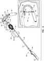
- Fig. 1is a schematic illustration of an expandable tissue anchor 120 that is configured to be anchored to a cardiac tissue wall at a target site such that a tensile force can be applied to expandable tissue anchor 120 and thus to the cardiac tissue wall, so as to move the cardiac tissue wall at the target site relative to adjacent cardiac tissue, in accordance with an application of the present invention.
- Expandable tissue anchor 120comprises an elongate tissue-coupling portion 130, which optionally is supported by an anchor head 196 at a proximal end 134 of tissue-coupling portion 130.
- Tissue-coupling portion 130is configured to be delivered in an unexpanded generally elongate configuration, such as described hereinbelow with reference to Fig.
- Tissue-coupling portion 130is further configured, upon deployment, to expand on the second side of the cardiac tissue wall, such as described hereinbelow with reference to Fig. 2B .
- Figs. 1 and 2Bshow tissue-coupling portion 130 expanded.
- expanded tissue-coupling portion 130has less than one turn, as shown in the figures, while for other applications, expanded tissue-coupling portion 130 has one turn (configuration not shown) or more than one turn (configuration not shown, but, for example, may be as shown in Figs. 5B-D, 6A-B, 7A-B, 9A-G, and/or 91 of above-mentioned PCT Publication WO 2016/087934 ).
- Expandable tissue anchor 120further comprises a flexible elongate tension member 146 coupled to a portion of tissue-coupling portion 130 of expandable tissue anchor 120.
- a flexible elongate tension member 146coupled to a portion of tissue-coupling portion 130 of expandable tissue anchor 120.
- the tensile forcecan be applied to tissue-coupling portion 130 after it has been expanded.
- the tensile forcemay have the benefit of bringing the anchor close to the tissue wall to which it is applied.
- an anchor system 150is provided that comprises expandable tissue anchor 120 and a tether 152 affixed to flexible elongate tension member 146 such that the tensile force can be applied to expandable tissue anchor 120 via tether 152 and flexible elongate tension member 146.
- expandable tissue anchor 120further comprises a tube 154 that surrounds a proximal portion of flexible elongate tension member 146.
- anchor system 150further comprises a second tissue anchor, separate and distinct from expandable tissue anchor 120, such as is shown in above-mentioned PCT Publication WO 2016/087934 .
- the second tissue anchor, and additional anchors if so desiredis couplable or coupled to expandable tissue anchor 120 by one or more tethers that include tether 152.
- Expandable tissue anchor 120further comprises a sleeve 190 that encloses a portion of flexible elongate tension member 146 between (a) tissue-coupling portion 130 of expandable tissue anchor 120 and (b) a distal opening 194 of a passage 191 through expandable tissue anchor 120, such that expanded tissue-coupling portion 130 (and, optionally, sleeve 190) can be drawn tightly against the second side of the cardiac tissue wall at the target site when the tensile force is applied to tissue-coupling portion 130.
- Distal opening 194 of passage 191is typically located near (e.g., at) a distal end 192 of anchor head 196. A portion of flexible elongate tension member 146 is slidably disposed through passage 191.
- passage 191is defined by anchor head 196 (as shown).
- distal opening 194may be defined by a tubular anchor shaft 132 that anchor head 196 comprises; anchor head 196 may optionally implement techniques described in above-mentioned PCT Publication WO 2016/087934 .
- anchor head 196comprises one or more collars 197, such as distal and proximal collars 197A and 197B, as shown, or exactly one collar 197 (configuration not shown).
- distal opening 194is defined by a distal end of distal collar 197A (as shown in Figs. 1 and 2A-C ) or a distal end of the exactly one collar 197 (configuration not shown).
- distal opening 194is defined by a lateral surface of the distal collar, such as described hereinbelow with reference to Fig. 3 .
- passage 191includes more than one passage 191, as shown.
- passage 191is alternatively or additionally defined by another portion of expandable tissue anchor 120, such as both tissue-coupling portion 130 of expandable tissue anchor 120 and anchor head 196 of expandable tissue anchor 120, such as shown in Fig. 4 , described hereinbelow.
- Passage 191is typically a channel, but may also be a groove (e.g., a U-shaped groove).
- Sleeve 190 and passage 191are sized and shaped such that the size and shape of passage 191 prevent proximal movement of sleeve 190 past passage 191 (e.g., prevent proximal movement of sleeve 190 into distal opening 194).
- Sleeve 190 and passage 191thus limit movement of tissue-coupling portion 130 toward distal end 192 of anchor head 196 upon application of the tensile force to flexible elongate tension member 146.
- sleeve 190has sufficient axial stiffness and too large an outer diameter to pass through passage 191 (e.g., including distal opening 194), and a distal (far) end 193 of sleeve 190 contacts tissue-coupling portion 130 near a junction 195 between flexible elongate tension member 146 and tissue-coupling portion 130, such as shown in Fig. 2C .
- Sleeve 190because of its axial stiffness, thus limits compression and deformation of expanded tissue-coupling portion 130 by flexible elongate tension member 146. A portion of the load (tension) applied by flexible elongate tension member 146 brings sleeve 190 into contact with expandable tissue anchor 120 near or at distal opening 194.
- Additional load (tension) applied by flexible elongate tension member 146(a) increases the total load on expanded tissue-coupling portion 130 (without further compressing or deforming expanded tissue-coupling portion 130), (b) optionally is diverted to elastic or plastic deformation of sleeve 190, and (c) pulls on the entire expandable tissue anchor 120.
- sleeve 190Attachment of sleeve 190 to flexible elongate tension member 146 is relatively simple during manufacture of expandable tissue anchor 120, as sleeve 190 need not be, and indeed typically is not, axially fixed to flexible elongate tension member 146. Even though sleeve 190 is typically axially slidable along flexible elongate tension member 146, the sleeve nevertheless serves its compression-limiting function, as described hereinabove.
- sleeve 190may generally increase the contact area between flexible elongate tension member 146 and the second site of the cardiac tissue wall. As a result, sleeve 190 may generally reduce the likelihood of flexible elongate tension member 146 cutting the cardiac tissue wall, particularly if the tissue is diseased.
- sleeve 190has an outer diameter of at least 0.5 mm, no more than 1 mm, and/or between 0.5 and 1 mm, such as 0.75 mm.
- sleeve 190has a length of at least 2 mm, no more than 6 mm, and/or between 2 and 6 mm, such as between 3 and 5 mm, e.g., 4 mm.
- sleeve 190comprises PET, PEEK, a closely wound metal coil spring, porous ePTFE, or woven PET fiber.
- tissue-coupling portion 130once expanded on the second side of the cardiac tissue wall, such as described hereinbelow with reference to Fig. 2B , assumes a shape generally orthogonal to anchor head 196, as shown in Fig. 1 , although it need not be orthogonal.
- anchor head 196further comprises a sealing element 174, which is sized and shaped to be inserted with anchor head 196 into an incision through the cardiac tissue wall. Sealing element 174, along with at least a portion of anchor head 196, remains in the incision upon completion of the implantation of expandable tissue anchor 120. Sealing element 174 promotes hemostasis to provide sealing of the incision.
- sealing element 174comprises a mesh, which may comprise Nitinol, covered with a membrane. The membrane may comprise a bioabsorbable polymer, which breaks down after healing and hemostasis occur.
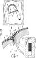
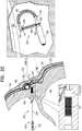
- FIGs. 2A-Care schematic illustrations of a method of deploying expandable tissue anchor 120 through a myocardial tissue wall 160.
- expandable tissue anchor 120may also be deployed through other cardiac tissue walls, such as the interatrial septum, either at or not at the fossa ovalis, or through other non-cardiac tissue walls.
- the tissue anchors described hereinmay be deployed in any number of bodily locations where it is desired to anchor into or behind tissue for purposes of moving such tissue relative to adjacent tissue.
- expandable tissue anchor 120is delivered to a target site, such as a cardiac chamber, in an unexpanded generally elongate configuration within a deployment tool 170, which may comprise a hollow needle 172.
- the cardiac chambermay be a right atrium 164 (as shown), a right ventricle 166 (configuration not shown), a left atrium (configuration not shown), or a left ventricle (configuration not shown).
- hollow needle 172is used to puncture through a first side of a myocardial tissue wall 160 and visceral pericardium 182 (which is part of the epicardium), avoiding vasculature such as the right coronary artery (RCA) 178.
- RCAright coronary artery
- deployment tool 170is then further directed into the pericardial cavity 180 between visceral pericardium 182 and parietal pericardium 184, carefully avoiding puncturing parietal pericardium 184 and fibrous pericardium 186.
- tissue-coupling portion 130expands on the second side of myocardial tissue wall 160, thereby anchoring expandable tissue anchor 120 to myocardial tissue wall 160.
- expanded tissue-coupling portion 130(and, optionally, sleeve 190) is tightly drawn against the second side of myocardial tissue wall 160 at the target site by applying a tensile force, using tether 152, to tissue-coupling portion 130 and thus to myocardial tissue wall 160.
- Application of the tensile forcepartially compresses expanded tissue-coupling portion 130, until passage 191 prevents proximal movement of sleeve 190 past passage 191, thereby limiting movement of tissue-coupling portion 130 toward distal end 192 of anchor head 196 and thus further compression and deformation of expanded tissue-coupling portion 130.
- tissue-coupling portion 130(and sleeve 190) is delivered through myocardial tissue wall 160, into pericardial cavity 180, generally alongside and against parietal pericardium 184, without penetrating the parietal pericardium 184.
- a second tissue anchoris implanted, separate and distinct from expandable tissue anchor 120.
- tissue-coupling portion 130comprises a tip 188, which is fixed to a distal end of a wire 189 of tissue-coupling portion 130.
- Tip 188at a widest longitudinal site along tip 188, has a greatest outer cross-sectional area that equals at least 150% (e.g., at least 200%, or at least 300%) of an average cross-sectional area of wire 189.
- the cross-sectional area of tip 188is measured perpendicular to a central longitudinal axis of tip 188.
- the cross-sectional area of wire 189is measured perpendicular to a central longitudinal axis of the wire, and is not a cross-sectional area of tissue-coupling portion 130.
- Tip 188temporarily serves as an atraumatic distal end of hollow needle 172 of deployment tool 170 when the tip is removably coupled to a distal end of hollow needle 172, as shown in Fig. 2A .
- hollow needle 172 of deployment tool 170has an outer cross-sectional area which equals between 90% and 110% (e.g., 100%) of the greatest outer cross-sectional area of tip 188, and tip 188 is shaped so as to removably engage the distal end of hollow needle 172, such as shown in Fig. 2A .
- tip 188is smaller than the internal diameter of hollow needle 172, allowing tip 188 to be retracted into the needle.
- Wire 189may be solid or hollow (i.e., tubular).
- wire 189comprises a shape-memory alloy, which is configured to automatically transition to a predetermined shape upon deployment of tissue-coupling portion 130 on the second side of the cardiac tissue wall.
- tissue-coupling portion 130comprises tip 188, while for others of these applications, tissue-coupling portion 130 does not comprise tip 188.
- expandable tissue anchor 120further comprises a second sleeve 198, which encloses a portion of wire 189 of tissue-coupling portion 130.
- Second sleeve 198serves to increase the contact area between tissue-coupling portion 130 and the second site of the cardiac tissue wall. As a result, second sleeve 198 may generally reduce the likelihood of wire 189 cutting the cardiac tissue wall, particularly if the tissue is diseased.
- second sleeve 198has an inner diameter of 0.5 mm and an outer diameter of 1.0 mm, and/or may comprise, for example, porous ePTFE or woven PET fiber. The combined profile of sleeve 190 and second sleeve 198 is less than the inner diameter of hollow needle 172.
- FIG. 3is a schematic illustration of an expandable tissue anchor 220, in accordance with an application of the present invention. Except as described below, expandable tissue anchor 220 is generally similar to expandable tissue anchor 120, described hereinabove with reference to Figs. 1 and 2A-C , and like reference numerals refer to like parts. Expandable tissue anchor 220 may implement any of the techniques described hereinabove for expandable tissue anchor 120, including, for example, sealing element 174, even though the sealing element is not shown in Fig. 3 .
- an anchor system 250comprises expandable tissue anchor 220 and tether 152 affixed to flexible elongate tension member 146 such that the tensile force can be applied to expandable tissue anchor 220 via tether 152 and flexible elongate tension member 146.
- An anchor head 296 of expandable tissue anchor 220supports elongate tissue-coupling portion 130 at a proximal end of the tissue-coupling portion.
- a lateral surface 299 of anchor head 296, typically near a distal end 292 of anchor head 296,is shaped so as to define at least a portion of a distal opening 294 of a passage 291 through expandable tissue anchor 220.
- anchor head 296comprises one or more collars 297, such as distal and proximal collars 297A and 297B, as shown.
- Lateral surface 299may be defined by distal collar 297A, typically near distal end 292 of anchor head 296.
- anchor head 296comprises exactly one collar 297, and distal opening 294 is defined by a lateral surface of the exactly one collar (configuration not shown). Further alternatively, anchor head 296 does not comprise any collars 297, and distal opening 294 of passage 291 is defined by a lateral wall of another portion of anchor head 296, such as of a tubular anchor shaft 232 that anchor head 296 comprises (configuration not shown).
- passage 291includes more than one passage 291, as shown. Passage 291 is typically a channel, but may also be a groove (e.g., a U-shaped groove).
- a portion of flexible elongate tension member 146is slidably disposed through passage 291.
- Sleeve 190 and passage 291are sized and shaped such that the size and shape of passage 291 prevent proximal movement of sleeve 190 past passage 291 (e.g., prevent proximal movement of sleeve 190 into distal opening 294).
- Sleeve 190 and passage 291thus limit movement of tissue-coupling portion 130 toward distal end 192 of anchor head 196 upon application of the tensile force to flexible elongate tension member 146.
- sleeve 190has sufficient axial stiffness and too large an outer diameter to pass through passage 291 (e.g., including distal opening 294), and a distal (far) end of sleeve 190 contacts tissue-coupling portion 130 near a junction between flexible elongate tension member 146 and tissue-coupling portion 130, such as shown in Fig. 2C for expandable tissue anchor 120.
- Sleeve 190because of its axial stiffness, thus limits compression and deformation of expanded tissue-coupling portion 130 by flexible elongate tension member 146. A portion of the load (tension) applied by flexible elongate tension member 146 brings sleeve 190 into contact with lateral surface 299 of distal collar 297A near or at distal opening 194.
- Additional load (tension) applied by flexible elongate tension member 146(a) increases the total load on expanded tissue-coupling portion 130 (without further compressing or deforming expanded tissue-coupling portion 130), (b) optionally is diverted to elastic or plastic deformation of sleeve 190, and (c) pulls on the entire expandable tissue anchor 120.
- Locating distal opening 294 of passage 291 at least partially through lateral surface 299 of distal collar 297Amay reduce the load on the curved portion of flexible elongate tension member 146 in the vicinity of distal opening 294.
- any damage to the proximal end of sleeve 190is reduced or avoided because the proximal end of sleeve 190 is oriented perpendicularly with distal opening 294 at the point of contact with the distal opening.
- flexible elongate tension member 146is not subject to shear between sleeve 190 and the edge of distal opening 294.
- FIG. 4is a schematic illustration of an expandable tissue anchor 320, in accordance with an application of the present invention. Except as described below, expandable tissue anchor 320 is generally similar to expandable tissue anchor 120, described hereinabove with reference to Figs. 1 and 2A-C , and like reference numerals refer to like parts. Expandable tissue anchor 220 may implement any of the techniques described hereinabove for expandable tissue anchor 120.
- an anchor system 350is provided that comprises expandable tissue anchor 320 and tether 152 affixed to flexible elongate tension member 146 such that the tensile force can be applied to expandable tissue anchor 320 via tether 152 and flexible elongate tension member 146.
- a passage 391 through expandable tissue anchor 320is defined at least in part by tissue-coupling portion 130 of expandable tissue anchor 320.
- a distal opening 394 of passage 391may be defined by wire 189 of tissue-coupling portion 130, which, in this configuration, includes at least a portion that is hollow (i.e., tubular), through which a portion of flexible elongate tension member 146 passes.
- passage 391is also defined by (a) an anchor head 396 of expandable tissue anchor 120 that supports elongate tissue-coupling portion 130 at a proximal end of the tissue-coupling portion.
- anchor head 396comprises one or more collars 397, such as distal and proximal collars 397A and 397B, as shown, or exactly one collar 397, and passage 391 passes through the one or more collars 397.
- passage 391includes more than one passage 391, as shown.
- Passage 391is typically a channel, but may also be a groove (e.g., a U-shaped groove).
Landscapes
- Health & Medical Sciences (AREA)
- Life Sciences & Earth Sciences (AREA)
- Cardiology (AREA)
- Surgery (AREA)
- Engineering & Computer Science (AREA)
- Public Health (AREA)
- Heart & Thoracic Surgery (AREA)
- Biomedical Technology (AREA)
- Veterinary Medicine (AREA)
- Animal Behavior & Ethology (AREA)
- General Health & Medical Sciences (AREA)
- Nuclear Medicine, Radiotherapy & Molecular Imaging (AREA)
- Medical Informatics (AREA)
- Molecular Biology (AREA)
- Transplantation (AREA)
- Rheumatology (AREA)
- Vascular Medicine (AREA)
- Oral & Maxillofacial Surgery (AREA)
- Surgical Instruments (AREA)
Description
- The present application claims the benefit of
US Provisional Application 62/516,894, filed June 8, 2017 - The present invention relates generally to tissue anchors, and specifically to tissue anchors for implantation at cardiac sites.
- Tissue anchors are used for anchoring elements, such as pacemaker electrode leads or sutures, to tissue, such as bone or soft tissue.
PCT Publication WO 2016/087934 to Gilmore et al . describes a tissue anchor that includes a shaft, a tissue-coupling element, and a flexible elongate tension member. The tissue-coupling element includes a wire, which is shaped as an open loop coil having, in some applications, more than one coil revolution when the tissue anchor is unconstrained, i.e., expanded from a linear state to a coiled state. The tension member includes a distal portion, that is fixed to a site on the open loop coil, a proximal portion, which has a longitudinal segment that runs alongside at least a portion of the shaft, and a crossing portion, which (i) is disposed between the distal and the proximal portions along the tension member, and (ii) crosses at least a portion of the open loop when the tissue anchor is expanded. The tissue anchor is configured to allow relative axial motion between the at least a portion of the shaft and the longitudinal segment of the proximal portion of the tension member when the tissue anchor is expanded. For some applications, a head of the tissue anchor is shaped so as to define a passage in which the proximal portion of the flexible elongate tension member is slidably disposed. The flexible elongate tension member comprises a locking stopper, which is axially fixed to the proximal or the crossing portion of the flexible elongate tension member. The locking stopper and the passage are sized and shaped such that the size and shape of the passage prevent proximal movement of the locking stopper past the passage. The locking stopper limits the total load that can be applied to the open loop by the flexible elongate tension member, thereby reducing excessive, unnecessary strain on the open loop. Additional load (tension) that is applied by the flexible elongate tension member pulls on the entire anchor, and does not further increase the load applied across the open loop. EP 3068311 relates to off-center tissue anchors, and discloses an expandable tissue anchor according to the pre-characterizing portion of appended claim 1.US 2011/0106245 relates to repair of an atrioventricular valve, and discloses apparatus comprising a tissue anchor.- In accordance with the present invention, there is provided an expandable tissue anchor as defined in appended independent claim 1. Embodiments of the present invention are defined in appended claims which depend upon independent claim 1. Methods of using the expandable tissue anchor are presented as a way to understand the invention and do not form part of the invention.
- Embodiments of the present invention provide expandable tissue anchors that are deliverable to a cardiac chamber in an unexpanded generally elongate configuration within a deployment tool. The expandable tissue anchors are configured to be anchored to a cardiac tissue wall at a target site such that a tensile force can be applied to the expandable tissue anchors and thus to the cardiac tissue wall, once the expandable tissue anchors are deployed, so as to move the cardiac tissue wall at the target site relative to adjacent cardiac tissue. For some applications, such motion alters the geometry of a cardiac valve, such as the tricuspid valve or the mitral valve.
- In some applications of the present invention, an expandable tissue anchor comprises an elongate tissue-coupling portion, which is configured to expand on a second side of the cardiac tissue wall. The expandable tissue anchor further comprises a flexible elongate tension member coupled to a portion of the tissue-coupling portion of the expandable tissue anchor, such that a tensile force can be applied to the tissue-coupling portion after it has been expanded. The expandable tissue anchor further comprises a sleeve that encloses a portion of the flexible elongate tension member between (a) the tissue-coupling portion of the expandable tissue anchor and (b) a distal opening of the passage. The sleeve and a passage through the expandable tissue anchor are sized and shaped such that the size and shape of the passage prevent proximal movement of the sleeve past the passage, thereby limiting compression and deformation of the expanded tissue-coupling portion by the flexible elongate tension member.
- There is therefore provided, in accordance with an application of the present invention, an expandable tissue anchor configured to be delivered to a cardiac chamber using a deployment tool, and to be anchored to a cardiac tissue wall at a target site such that a tensile force can be applied to the expandable tissue anchor and thus to the cardiac tissue wall, once the expandable tissue anchor is deployed, so as to move the cardiac tissue wall at the target site relative to adjacent cardiac tissue, the expandable tissue anchor including:
- an elongate tissue-coupling portion configured to be delivered in an unexpanded generally elongate configuration through the cardiac tissue wall from a first side of the cardiac tissue wall to a second side of the cardiac tissue wall, the tissue-coupling portion further configured to expand on the second side of the cardiac tissue wall;
- a flexible elongate tension member, which is coupled to a portion of the tissue-coupling portion of the expandable tissue anchor such that the tensile force can be applied to the tissue-coupling portion after it has been expanded, wherein a portion of the flexible elongate tension member is slidably disposed through a passage defined by the expandable tissue anchor;
- an anchor head that supports the tissue-coupling portion at a proximal end of the tissue-coupling portion; and
- a sleeve that encloses a portion of the flexible elongate tension member between (a) the tissue-coupling portion of the expandable tissue anchor and (b) a distal end of the passage, with the sleeve and the passage being sized and shaped such that the size and shape of the passage prevent proximal movement of the sleeve past the passage upon application of the tensile force to the flexible elongate tension member, thereby limiting compression and deformation of the expanded tissue-coupling portion by the flexible elongate tension member,
- characterized in that: the sleeve is axially slidable along the flexible elongate tension member, with the sleeve and the passage limiting movement of the tissue-coupling portion toward a distal end of the anchor head upon application of the tensile force to the flexible elongate tension member, because (a) the sleeve has sufficient axial stiffness and too large an outer diameter to pass through the passage, and (b) a distal end of the sleeve contacts the tissue-coupling portion near a junction between the flexible elongate tension member and the tissue-coupling portion; and
- the sleeve is configured such that the expanded tissue-coupling portion and the sleeve can be drawn tightly against the second side of the cardiac tissue wall at the target site when the tensile force is applied to the tissue-coupling portion after it has been expanded.
- For some applications, the expandable tissue anchor is configured such that when the cardiac tissue wall is a myocardial tissue wall, the tissue-coupling portion of the expandable tissue anchor can be advanced into the pericardial cavity between visceral pericardium and parietal pericardium, generally alongside and against the parietal pericardium, without penetrating the parietal pericardium.
- For some applications, the anchor head is shaped so as to define the passage.
- For some applications, a lateral surface of the anchor head is shaped so as to define at least a portion of the distal opening of the passage.
- For some applications, the anchor head includes a collar, which is shaped so as to define the distal opening of the passage.
- For some applications, a distal end of the collar is shaped so as to define the distal opening of the passage.
- For some applications, a lateral surface of the collar is shaped so as to define at least a portion of the distal opening of the passage.
- For some applications, the tissue-coupling portion of the expandable tissue anchor, once expanded on the second side of the cardiac tissue wall, assumes a shape generally orthogonal to the anchor head.
- There is further provided, in accordance with an application of the present invention, an anchor system including the expandable tissue anchor, wherein the anchor system further includes a tether affixed to the flexible elongate tension member such that the tensile force can be applied to the expandable tissue anchor via the tether and the flexible elongate tension member.
- There is still further provided a method for moving a cardiac tissue wall at a target site relative to adjacent cardiac tissue, the method including:
- delivering, to a cardiac chamber, an expandable tissue anchor in an unexpanded generally elongate configuration within a deployment tool, the expandable tissue anchor including (a) an elongate tissue-coupling portion, (b) a flexible elongate tension member coupled to a portion of the tissue-coupling portion, and (c) a sleeve that encloses a portion of the flexible elongate tension member between (i) the tissue-coupling portion of the expandable tissue anchor and (ii) a distal opening of a passage defined by the expandable tissue anchor, wherein a portion of the flexible elongate tension member is slidably disposed through the passage defined by the expandable tissue anchor;
- delivering the tissue-coupling portion in an unexpanded generally elongate configuration through the cardiac tissue wall from a first side of the wall to a second side of the wall, such that the tissue-coupling portion expands on the second side of the cardiac tissue wall, thereby anchoring the expandable tissue anchor to the cardiac tissue wall at the target site;
- partially compressing the expanded tissue-coupling portion by applying a tensile force to the flexible elongate tension member, until the passage prevents proximal movement of the sleeve past the passage, thereby limiting compression and deformation of the expanded tissue-coupling portion by the flexible elongate tension member; and
- after the passage prevents proximal movement of the sleeve past the passage, applying, to the flexible elongate tension member, additional tensile force that does not further compress or deform the expanded tissue-coupling portion, and thus is applied to the cardiac tissue wall, so as to move the cardiac tissue wall at the target site relative to the adjacent cardiac tissue.
- The expandable tissue anchor further includes an anchor head that supports the tissue-coupling portion at a proximal end of the tissue-coupling portion.
- For some applications, the anchor head is shaped so as to define the passage.
- For some applications, a lateral surface of the anchor head is shaped so as to define at least a portion of the distal opening of the passage.
- For some applications, the anchor head includes a collar, which is shaped so as to define the distal opening of the passage.
- For some applications, a distal end of the collar is shaped so as to define the distal opening of the passage.
- For some applications, a lateral surface of the collar is shaped so as to define at least a portion of the distal opening of the passage.
- For some applications, the tissue-coupling portion and the expandable tissue anchor, once expanded on the second side of the cardiac tissue wall, includes a configuration generally orthogonal to the anchor head.
- The sleeve is axially slidable along the flexible elongate tension member.
- Applying the tensile force to the flexible elongate tension member includes tightly drawing the expanded tissue-coupling portion and the sleeve against the second side of the cardiac tissue wall at the target site.
- For some applications, the cardiac tissue is a myocardial tissue wall, and delivering the tissue-coupling portion in the unexpanded generally elongate configuration through the cardiac tissue wall includes delivering the tissue-coupling portion through the cardiac tissue wall into the pericardial cavity between visceral pericardium and parietal pericardium, generally alongside and against the parietal pericardium, without penetrating the parietal pericardium.
- For some applications, applying the tensile force to the flexible elongate tension member includes applying the tensile force to a tether affixed to the flexible elongate tension member.
- The present invention will be more fully understood from the following detailed description of embodiments thereof, taken together with the drawings, in which:
Fig. 1 is a schematic illustration of an expandable tissue anchor that is configured to be anchored to a cardiac tissue wall at a target site, in accordance with an application of the present invention;Figs. 2A-C are schematic illustrations of a method of deploying the expandable tissue anchor ofFig. 1 through a myocardial tissue wall;Fig. 3 is a schematic illustration of another expandable tissue anchor, in accordance with an application of the present invention; andFig. 4 is a schematic illustration of yet another expandable tissue anchor, in accordance with an application of the present invention.Fig. 1 is a schematic illustration of anexpandable tissue anchor 120 that is configured to be anchored to a cardiac tissue wall at a target site such that a tensile force can be applied toexpandable tissue anchor 120 and thus to the cardiac tissue wall, so as to move the cardiac tissue wall at the target site relative to adjacent cardiac tissue, in accordance with an application of the present invention.Expandable tissue anchor 120 comprises an elongate tissue-coupling portion 130, which optionally is supported by ananchor head 196 at aproximal end 134 of tissue-coupling portion 130. Tissue-coupling portion 130 is configured to be delivered in an unexpanded generally elongate configuration, such as described hereinbelow with reference toFig. 2A , through the cardiac tissue wall from a first side of the wall to a second side of the wall, such as described hereinbelow with reference toFigs. 2A-C . Tissue-coupling portion 130 is further configured, upon deployment, to expand on the second side of the cardiac tissue wall, such as described hereinbelow with reference toFig. 2B .Figs. 1 and2B show tissue-coupling portion 130 expanded. For some applications, expanded tissue-coupling portion 130 has less than one turn, as shown in the figures, while for other applications, expanded tissue-coupling portion 130 has one turn (configuration not shown) or more than one turn (configuration not shown, but, for example, may be as shown in Figs. 5B-D, 6A-B, 7A-B, 9A-G, and/or 91 of above-mentionedPCT Publication WO 2016/087934 ).Expandable tissue anchor 120 further comprises a flexibleelongate tension member 146 coupled to a portion of tissue-coupling portion 130 ofexpandable tissue anchor 120. Through flexibleelongate tension member 146, or components equivalent thereto, the tensile force can be applied to tissue-coupling portion 130 after it has been expanded. When appliedin vivo, the tensile force may have the benefit of bringing the anchor close to the tissue wall to which it is applied. For some applications, ananchor system 150 is provided that comprisesexpandable tissue anchor 120 and atether 152 affixed to flexibleelongate tension member 146 such that the tensile force can be applied toexpandable tissue anchor 120 viatether 152 and flexibleelongate tension member 146. Optionally,expandable tissue anchor 120 further comprises atube 154 that surrounds a proximal portion of flexibleelongate tension member 146. For some applications,anchor system 150 further comprises a second tissue anchor, separate and distinct fromexpandable tissue anchor 120, such as is shown in above-mentionedPCT Publication WO 2016/087934 . For some applications, the second tissue anchor, and additional anchors if so desired, is couplable or coupled toexpandable tissue anchor 120 by one or more tethers that includetether 152.Expandable tissue anchor 120 further comprises asleeve 190 that encloses a portion of flexibleelongate tension member 146 between (a) tissue-coupling portion 130 ofexpandable tissue anchor 120 and (b) adistal opening 194 of apassage 191 throughexpandable tissue anchor 120, such that expanded tissue-coupling portion 130 (and, optionally, sleeve 190) can be drawn tightly against the second side of the cardiac tissue wall at the target site when the tensile force is applied to tissue-coupling portion 130.Distal opening 194 ofpassage 191 is typically located near (e.g., at) adistal end 192 ofanchor head 196. A portion of flexibleelongate tension member 146 is slidably disposed throughpassage 191. For some applications,passage 191 is defined by anchor head 196 (as shown). For example,distal opening 194 may be defined by atubular anchor shaft 132 that anchorhead 196 comprises;anchor head 196 may optionally implement techniques described in above-mentionedPCT Publication WO 2016/087934 . For some applications, in addition to or instead oftubular anchor shaft 132,anchor head 196 comprises one ormore collars 197, such as distal and proximal collars 197A and 197B, as shown, or exactly one collar 197 (configuration not shown). For some of these applications,distal opening 194 is defined by a distal end of distal collar 197A (as shown inFigs. 1 and 2A-C ) or a distal end of the exactly one collar 197 (configuration not shown). For other applications,distal opening 194 is defined by a lateral surface of the distal collar, such as described hereinbelow with reference toFig. 3 . For some applications,passage 191 includes more than onepassage 191, as shown. For some applications,passage 191 is alternatively or additionally defined by another portion ofexpandable tissue anchor 120, such as both tissue-coupling portion 130 ofexpandable tissue anchor 120 andanchor head 196 ofexpandable tissue anchor 120, such as shown inFig. 4 , described hereinbelow.Passage 191 is typically a channel, but may also be a groove (e.g., a U-shaped groove).Sleeve 190 andpassage 191 are sized and shaped such that the size and shape ofpassage 191 prevent proximal movement ofsleeve 190 past passage 191 (e.g., prevent proximal movement ofsleeve 190 into distal opening 194).Sleeve 190 andpassage 191 thus limit movement of tissue-coupling portion 130 towarddistal end 192 ofanchor head 196 upon application of the tensile force to flexibleelongate tension member 146. This is the case becausesleeve 190 has sufficient axial stiffness and too large an outer diameter to pass through passage 191 (e.g., including distal opening 194), and a distal (far) end 193 ofsleeve 190 contacts tissue-coupling portion 130 near ajunction 195 between flexibleelongate tension member 146 and tissue-coupling portion 130, such as shown inFig. 2C .Sleeve 190, because of its axial stiffness, thus limits compression and deformation of expanded tissue-coupling portion 130 by flexibleelongate tension member 146. A portion of the load (tension) applied by flexibleelongate tension member 146 bringssleeve 190 into contact withexpandable tissue anchor 120 near or atdistal opening 194. Additional load (tension) applied by flexible elongate tension member 146 (a) increases the total load on expanded tissue-coupling portion 130 (without further compressing or deforming expanded tissue-coupling portion 130), (b) optionally is diverted to elastic or plastic deformation ofsleeve 190, and (c) pulls on the entireexpandable tissue anchor 120.- Attachment of
sleeve 190 to flexibleelongate tension member 146 is relatively simple during manufacture ofexpandable tissue anchor 120, assleeve 190 need not be, and indeed typically is not, axially fixed to flexibleelongate tension member 146. Even thoughsleeve 190 is typically axially slidable along flexibleelongate tension member 146, the sleeve nevertheless serves its compression-limiting function, as described hereinabove. - In addition,
sleeve 190 may generally increase the contact area between flexibleelongate tension member 146 and the second site of the cardiac tissue wall. As a result,sleeve 190 may generally reduce the likelihood of flexibleelongate tension member 146 cutting the cardiac tissue wall, particularly if the tissue is diseased. - For some applications,
sleeve 190 has an outer diameter of at least 0.5 mm, no more than 1 mm, and/or between 0.5 and 1 mm, such as 0.75 mm. For some applications,sleeve 190 has a length of at least 2 mm, no more than 6 mm, and/or between 2 and 6 mm, such as between 3 and 5 mm, e.g., 4 mm. For some applications,sleeve 190 comprises PET, PEEK, a closely wound metal coil spring, porous ePTFE, or woven PET fiber. - For some applications, tissue-
coupling portion 130, once expanded on the second side of the cardiac tissue wall, such as described hereinbelow with reference toFig. 2B , assumes a shape generally orthogonal to anchorhead 196, as shown inFig. 1 , although it need not be orthogonal. - For some applications, as shown in
Fig. 1 ,anchor head 196 further comprises a sealingelement 174, which is sized and shaped to be inserted withanchor head 196 into an incision through the cardiac tissue wall.Sealing element 174, along with at least a portion ofanchor head 196, remains in the incision upon completion of the implantation ofexpandable tissue anchor 120.Sealing element 174 promotes hemostasis to provide sealing of the incision. For some applications, sealingelement 174 comprises a mesh, which may comprise Nitinol, covered with a membrane. The membrane may comprise a bioabsorbable polymer, which breaks down after healing and hemostasis occur. - Reference is now made to
Figs. 2A-C , which are schematic illustrations of a method of deployingexpandable tissue anchor 120 through amyocardial tissue wall 160. Although inFigs. 2A-C expandable tissue anchor 120 is shown deployed through a myocardial tissue wall,expandable tissue anchor 120 may also be deployed through other cardiac tissue walls, such as the interatrial septum, either at or not at the fossa ovalis, or through other non-cardiac tissue walls. Indeed, the tissue anchors described herein may be deployed in any number of bodily locations where it is desired to anchor into or behind tissue for purposes of moving such tissue relative to adjacent tissue. - As shown in
Fig. 2A ,expandable tissue anchor 120 is delivered to a target site, such as a cardiac chamber, in an unexpanded generally elongate configuration within adeployment tool 170, which may comprise ahollow needle 172. The cardiac chamber may be a right atrium 164 (as shown), a right ventricle 166 (configuration not shown), a left atrium (configuration not shown), or a left ventricle (configuration not shown). In one application,hollow needle 172 is used to puncture through a first side of amyocardial tissue wall 160 and visceral pericardium 182 (which is part of the epicardium), avoiding vasculature such as the right coronary artery (RCA) 178. For some applications,deployment tool 170 is then further directed into thepericardial cavity 180 betweenvisceral pericardium 182 andparietal pericardium 184, carefully avoiding puncturingparietal pericardium 184 andfibrous pericardium 186. - As shown in
Fig. 2B , tissue-coupling portion 130 expands on the second side ofmyocardial tissue wall 160, thereby anchoringexpandable tissue anchor 120 tomyocardial tissue wall 160. - As shown in
Fig. 2C , onceexpandable tissue anchor 120 has been anchored tomyocardial tissue wall 160 at the target site, expanded tissue-coupling portion 130 (and, optionally, sleeve 190) is tightly drawn against the second side ofmyocardial tissue wall 160 at the target site by applying a tensile force, usingtether 152, to tissue-coupling portion 130 and thus tomyocardial tissue wall 160. Application of the tensile force partially compresses expanded tissue-coupling portion 130, untilpassage 191 prevents proximal movement ofsleeve 190past passage 191, thereby limiting movement of tissue-coupling portion 130 towarddistal end 192 ofanchor head 196 and thus further compression and deformation of expanded tissue-coupling portion 130. Typically, afterpassage 191 prevents the proximal movement of thesleeve 190 past the passage, addition tensile force is applied to flexibleelongate tension member 146 that does not further compress or deform the expanded tissue-coupling portion 130. As a result, the additional tensile force is applied tomyocardial tissue wall 160 andmyocardial tissue wall 160 at the target site is moved relative to adjacent cardiac tissue. For some applications, such motion can have the benefit of altering the geometry of a nearby cardiac valve, such as the tricuspid valve or the mitral valve. - For some applications, after application of the tensile force, all or a portion of
sleeve 190 rests against the second side ofmyocardial tissue wall 160, generally helping prevent possible inadvertent cutting ofmyocardial tissue wall 160 by flexibleelongate tension member 146. For some applications, such as shown inFig. 2B , tissue-coupling portion 130 (and sleeve 190) is delivered throughmyocardial tissue wall 160, intopericardial cavity 180, generally alongside and againstparietal pericardium 184, without penetrating theparietal pericardium 184. For some applications, a second tissue anchor is implanted, separate and distinct fromexpandable tissue anchor 120. - Reference is made to
Figs. 1 and 2A-C . For some applications, tissue-coupling portion 130 comprises atip 188, which is fixed to a distal end of awire 189 of tissue-coupling portion 130.Tip 188, at a widest longitudinal site alongtip 188, has a greatest outer cross-sectional area that equals at least 150% (e.g., at least 200%, or at least 300%) of an average cross-sectional area ofwire 189. (The cross-sectional area oftip 188 is measured perpendicular to a central longitudinal axis oftip 188. Similarly, the cross-sectional area ofwire 189 is measured perpendicular to a central longitudinal axis of the wire, and is not a cross-sectional area of tissue-coupling portion 130.)Tip 188 temporarily serves as an atraumatic distal end ofhollow needle 172 ofdeployment tool 170 when the tip is removably coupled to a distal end ofhollow needle 172, as shown inFig. 2A . For some applications,hollow needle 172 ofdeployment tool 170 has an outer cross-sectional area which equals between 90% and 110% (e.g., 100%) of the greatest outer cross-sectional area oftip 188, andtip 188 is shaped so as to removably engage the distal end ofhollow needle 172, such as shown inFig. 2A . Alternatively,tip 188 is smaller than the internal diameter ofhollow needle 172, allowingtip 188 to be retracted into the needle.Wire 189 may be solid or hollow (i.e., tubular). - For some applications,
wire 189 comprises a shape-memory alloy, which is configured to automatically transition to a predetermined shape upon deployment of tissue-coupling portion 130 on the second side of the cardiac tissue wall. For some of these applications, tissue-coupling portion 130 comprisestip 188, while for others of these applications, tissue-coupling portion 130 does not comprisetip 188. - Reference is still made to
Figs. 1 and 2A-C . For some applications,expandable tissue anchor 120 further comprises asecond sleeve 198, which encloses a portion ofwire 189 of tissue-coupling portion 130.Second sleeve 198 serves to increase the contact area between tissue-coupling portion 130 and the second site of the cardiac tissue wall. As a result,second sleeve 198 may generally reduce the likelihood ofwire 189 cutting the cardiac tissue wall, particularly if the tissue is diseased. For some applications,second sleeve 198 has an inner diameter of 0.5 mm and an outer diameter of 1.0 mm, and/or may comprise, for example, porous ePTFE or woven PET fiber. The combined profile ofsleeve 190 andsecond sleeve 198 is less than the inner diameter ofhollow needle 172. - Reference is now made to
Fig. 3 , which is a schematic illustration of anexpandable tissue anchor 220, in accordance with an application of the present invention. Except as described below,expandable tissue anchor 220 is generally similar toexpandable tissue anchor 120, described hereinabove with reference toFigs. 1 and 2A-C , and like reference numerals refer to like parts.Expandable tissue anchor 220 may implement any of the techniques described hereinabove forexpandable tissue anchor 120, including, for example, sealingelement 174, even though the sealing element is not shown inFig. 3 . For some applications, ananchor system 250 is provided that comprisesexpandable tissue anchor 220 andtether 152 affixed to flexibleelongate tension member 146 such that the tensile force can be applied toexpandable tissue anchor 220 viatether 152 and flexibleelongate tension member 146. - An
anchor head 296 ofexpandable tissue anchor 220 supports elongate tissue-coupling portion 130 at a proximal end of the tissue-coupling portion. Alateral surface 299 ofanchor head 296, typically near adistal end 292 ofanchor head 296, is shaped so as to define at least a portion of adistal opening 294 of apassage 291 throughexpandable tissue anchor 220. For some applications,anchor head 296 comprises one or more collars 297, such as distal and proximal collars 297A and 297B, as shown.Lateral surface 299 may be defined by distal collar 297A, typically neardistal end 292 ofanchor head 296. Alternatively,anchor head 296 comprises exactly one collar 297, anddistal opening 294 is defined by a lateral surface of the exactly one collar (configuration not shown). Further alternatively,anchor head 296 does not comprise any collars 297, anddistal opening 294 ofpassage 291 is defined by a lateral wall of another portion ofanchor head 296, such as of atubular anchor shaft 232 that anchorhead 296 comprises (configuration not shown). For some applications,passage 291 includes more than onepassage 291, as shown.Passage 291 is typically a channel, but may also be a groove (e.g., a U-shaped groove). - A portion of flexible
elongate tension member 146 is slidably disposed throughpassage 291.Sleeve 190 andpassage 291 are sized and shaped such that the size and shape ofpassage 291 prevent proximal movement ofsleeve 190 past passage 291 (e.g., prevent proximal movement ofsleeve 190 into distal opening 294).Sleeve 190 andpassage 291 thus limit movement of tissue-coupling portion 130 towarddistal end 192 ofanchor head 196 upon application of the tensile force to flexibleelongate tension member 146. This is the case becausesleeve 190 has sufficient axial stiffness and too large an outer diameter to pass through passage 291 (e.g., including distal opening 294), and a distal (far) end ofsleeve 190 contacts tissue-coupling portion 130 near a junction between flexibleelongate tension member 146 and tissue-coupling portion 130, such as shown inFig. 2C forexpandable tissue anchor 120.Sleeve 190, because of its axial stiffness, thus limits compression and deformation of expanded tissue-coupling portion 130 by flexibleelongate tension member 146. A portion of the load (tension) applied by flexibleelongate tension member 146 bringssleeve 190 into contact withlateral surface 299 of distal collar 297A near or atdistal opening 194. Additional load (tension) applied by flexible elongate tension member 146 (a) increases the total load on expanded tissue-coupling portion 130 (without further compressing or deforming expanded tissue-coupling portion 130), (b) optionally is diverted to elastic or plastic deformation ofsleeve 190, and (c) pulls on the entireexpandable tissue anchor 120. - Locating
distal opening 294 ofpassage 291 at least partially throughlateral surface 299 of distal collar 297A may reduce the load on the curved portion of flexibleelongate tension member 146 in the vicinity ofdistal opening 294. In addition, any damage to the proximal end ofsleeve 190 is reduced or avoided because the proximal end ofsleeve 190 is oriented perpendicularly withdistal opening 294 at the point of contact with the distal opening. Further, in this arrangement, flexibleelongate tension member 146 is not subject to shear betweensleeve 190 and the edge ofdistal opening 294. - Reference is now made to
Fig. 4 , which is a schematic illustration of anexpandable tissue anchor 320, in accordance with an application of the present invention. Except as described below,expandable tissue anchor 320 is generally similar toexpandable tissue anchor 120, described hereinabove with reference toFigs. 1 and 2A-C , and like reference numerals refer to like parts.Expandable tissue anchor 220 may implement any of the techniques described hereinabove forexpandable tissue anchor 120. For some applications, ananchor system 350 is provided that comprisesexpandable tissue anchor 320 andtether 152 affixed to flexibleelongate tension member 146 such that the tensile force can be applied toexpandable tissue anchor 320 viatether 152 and flexibleelongate tension member 146. - In this configuration, a
passage 391 throughexpandable tissue anchor 320 is defined at least in part by tissue-coupling portion 130 ofexpandable tissue anchor 320. Adistal opening 394 ofpassage 391 may be defined bywire 189 of tissue-coupling portion 130, which, in this configuration, includes at least a portion that is hollow (i.e., tubular), through which a portion of flexibleelongate tension member 146 passes. Optionally,passage 391 is also defined by (a) ananchor head 396 ofexpandable tissue anchor 120 that supports elongate tissue-coupling portion 130 at a proximal end of the tissue-coupling portion. For some applications,anchor head 396 comprises one or more collars 397, such as distal and proximal collars 397A and 397B, as shown, or exactly one collar 397, andpassage 391 passes through the one or more collars 397. For some applications,passage 391 includes more than onepassage 391, as shown.Passage 391 is typically a channel, but may also be a groove (e.g., a U-shaped groove). - For some applications, techniques and apparatus described in one or more of the following applications are combined with techniques and apparatus described herein:
US Patent 8,475,525 to Maisano et al. ;US Patent 8,961,596 to Maisano et al.;US Patent 8,961,594 to Maisano et al. ;PCT Publication WO 2011/089601 ;US Patent 9,241,702 to Maisano US Provisional Application 61/750,427, filed January 9, 2013 US Provisional Application 61/783,224, filed March 14, 2013 US Provisional Application 61/897,491, filed October 30, 2013 US Provisional Application 61/897,509, filed October 30, 2013 US Patent 9,307,980 to Gilmore et al. PCT Publication WO 2014/108903 ;PCT Publication WO 2014/141239 ;US Provisional Application 62/014,397, filed June 19, 2014 PCT Publication WO 2015/063580 ;US Patent Application Publication 2015/0119936 ;US Provisional Application 62/086,269, filed December 2, 2014 US Provisional Application 62/131,636, filed March 11, 2015 US Provisional Application 62/167,660, filed May 28, 2015 PCT Publication WO 2015/193728 ;PCT Publication WO 2016/087934 ;US Patent Application Publication 2016/0235533 ;US Patent Application Publication 2016/0242762 ;PCT Publication WO 2016/189391 ;US Patent Application Publication 2016/0262741 ;US Provisional Application 62/376,685, filed August 18, 2016 US Provisional Application 62/456,206, filed February 8, 2017 US Provisional Application 62/456,202, filed February 8, 2017 US Provisional Application 62/465,410, filed March 1, 2017 US Provisional Application 62/465,400, filed March 1, 2017 - It will be appreciated by persons skilled in the art that the present invention is not limited to what has been particularly shown and described hereinabove. Rather, the scope of the present invention is defined by the appended claims, and may include both combinations and subcombinations of the various features described hereinabove, as well as variations and modifications thereof that are not in the prior art, which would occur to persons skilled in the art upon reading the foregoing description.
Claims (9)
- An expandable tissue anchor (120, 220, 320) configured to be delivered to a cardiac chamber using a deployment tool (170), and to be anchored to a cardiac tissue wall at a target site such that a tensile force can be applied to the expandable tissue anchor (120, 220, 320) and thus to the cardiac tissue wall, once the expandable tissue anchor (120, 220, 320) is deployed, so as to move the cardiac tissue wall at the target site relative to adjacent cardiac tissue, the expandable tissue anchor (120, 220, 320) comprising:an elongate tissue-coupling portion (130) configured to be delivered in an unexpanded generally elongate configuration through the cardiac tissue wall from a first side of the cardiac tissue wall to a second side of the cardiac tissue wall, the tissue-coupling portion (130) further configured to expand on the second side of the cardiac tissue wall;a flexible elongate tension member (146), which is coupled to a portion of the tissue-coupling portion (130) of the expandable tissue anchor (120, 220, 320) such that the tensile force can be applied to the tissue-coupling portion (130) after it has been expanded, wherein a portion of the flexible elongate tension member (146) is slidably disposed through a passage (191, 291, 391) defined by the expandable tissue anchor (120, 220, 320);an anchor head (196, 296, 396) that supports the tissue-coupling portion (130) at a proximal end (134) of the tissue-coupling portion (130); anda sleeve (190) that encloses a portion of the flexible elongate tension member (146) between (a) the tissue-coupling portion (130) of the expandable tissue anchor (120, 220, 320) and (b) a distal opening (194, 294, 394) of the passage (191, 291, 391), with the sleeve (190) and the passage (191, 291, 391) being sized and shaped such that the size and shape of the passage (191, 291, 391) prevent proximal movement of the sleeve (190) past the passage (191, 291, 391) upon application of the tensile force to the flexible elongate tension member (146), thereby limiting compression and deformation of the expanded tissue-coupling portion (130) by the flexible elongate tension member (146),characterised in that:the sleeve (190) is axially slidable along the flexible elongate tension member (146), with the sleeve (190) and the passage (191, 291) limiting movement of the tissue-coupling portion (130) toward a distal end (192, 292) of the anchor head (196, 296) upon application of the tensile force to the flexible elongate tension member (146), because (a) the sleeve (190) has sufficient axial stiffness and too large an outer diameter to pass through the passage (191, 291), and (b) a distal end (193) of the sleeve (190) contacts the tissue-coupling portion (130) near a junction (195) between the flexible elongate tension member (146) and the tissue-coupling portion (130); andthe sleeve (190) is configured such that the expanded tissue-coupling portion (130) and the sleeve (190) can be drawn tightly against the second side of the cardiac tissue wall at the target site when the tensile force is applied to the tissue-coupling portion (130) after it has been expanded.
- The expandable tissue anchor (120, 220, 320) according to Claim 1, wherein the expandable tissue anchor (120, 220, 320) is configured such that when the cardiac tissue wall is a myocardial tissue wall, the tissue-coupling portion (130) of the expandable tissue anchor (120, 220, 320) can be advanced into the pericardial cavity between visceral pericardium and parietal pericardium, generally alongside and against the parietal pericardium, without penetrating the parietal pericardium.
- The expandable tissue anchor (120, 220, 320) according to Claim 1 or Claim 2, wherein the anchor head (196, 296, 396) is shaped so as to define the passage (191, 291, 391).
- The expandable tissue anchor (220) according to Claim 3, wherein a lateral surface (299) of the anchor head (299) is shaped so as to define at least a portion of the distal opening (294) of the passage (291).
- The expandable tissue anchor (120, 220, 320) according to Claim 3, wherein the anchor head comprises a collar (197, 297, 397), which is shaped so as to define the distal opening (194, 294, 394) of the passage (191, 291, 391).
- The expandable tissue anchor (120) according to Claim 5, wherein a distal end of the collar (197) is shaped so as to define the distal opening (194) of the passage (191).
- The expandable tissue anchor (220) according to Claim 5, wherein a lateral surface (299) of the collar (297) is shaped so as to define at least a portion of the distal opening (294) of the passage (291).
- The expandable tissue anchor (120, 220, 320) according to Claim 1 or Claim 2, wherein the tissue-coupling portion (130) of the expandable tissue anchor (120, 220, 320), once expanded on the second side of the cardiac tissue wall, assumes a shape generally orthogonal to the anchor head (196, 296, 396).
- An anchor system (150, 250, 350) comprising the expandable tissue anchor (120, 220, 320) according to Claim 1, wherein the anchor system (150, 250, 350) further comprises a tether (152) affixed to the flexible elongate tension member (146) such that the tensile force can be applied to the expandable tissue anchor (120, 220, 320) via the tether (152) and the flexible elongate tension member (146).
Applications Claiming Priority (2)
| Application Number | Priority Date | Filing Date | Title |
|---|---|---|---|
| US201762516894P | 2017-06-08 | 2017-06-08 | |
| PCT/US2018/036609WO2018227048A1 (en) | 2017-06-08 | 2018-06-08 | Tissue anchor with tether stop |
Publications (2)
| Publication Number | Publication Date |
|---|---|
| EP3634255A1 EP3634255A1 (en) | 2020-04-15 |
| EP3634255B1true EP3634255B1 (en) | 2020-08-12 |
Family
ID=62751596
Family Applications (1)
| Application Number | Title | Priority Date | Filing Date |
|---|---|---|---|
| EP18734730.7AActiveEP3634255B1 (en) | 2017-06-08 | 2018-06-08 | Tissue anchor with tether stop |
Country Status (5)
| Country | Link |
|---|---|
| US (1) | US20180353297A1 (en) |
| EP (1) | EP3634255B1 (en) |
| JP (1) | JP6736193B2 (en) |
| CN (1) | CN110740693B (en) |
| WO (1) | WO2018227048A1 (en) |
Cited By (15)
| Publication number | Priority date | Publication date | Assignee | Title |
|---|---|---|---|---|
| US10940001B2 (en) | 2012-05-30 | 2021-03-09 | Neovasc Tiara Inc. | Methods and apparatus for loading a prosthesis onto a delivery system |
| US11311376B2 (en) | 2019-06-20 | 2022-04-26 | Neovase Tiara Inc. | Low profile prosthetic mitral valve |
| US11357622B2 (en) | 2016-01-29 | 2022-06-14 | Neovase Tiara Inc. | Prosthetic valve for avoiding obstruction of outflow |
| US11389291B2 (en) | 2013-04-04 | 2022-07-19 | Neovase Tiara Inc. | Methods and apparatus for delivering a prosthetic valve to a beating heart |
| US11413139B2 (en) | 2011-11-23 | 2022-08-16 | Neovasc Tiara Inc. | Sequentially deployed transcatheter mitral valve prosthesis |
| US11419720B2 (en) | 2010-05-05 | 2022-08-23 | Neovasc Tiara Inc. | Transcatheter mitral valve prosthesis |
| US11464631B2 (en) | 2016-11-21 | 2022-10-11 | Neovasc Tiara Inc. | Methods and systems for rapid retraction of a transcatheter heart valve delivery system |
| US11491006B2 (en) | 2019-04-10 | 2022-11-08 | Neovasc Tiara Inc. | Prosthetic valve with natural blood flow |
| US11497602B2 (en) | 2012-02-14 | 2022-11-15 | Neovasc Tiara Inc. | Methods and apparatus for engaging a valve prosthesis with tissue |
| US11602429B2 (en) | 2019-04-01 | 2023-03-14 | Neovasc Tiara Inc. | Controllably deployable prosthetic valve |
| US11737872B2 (en) | 2018-11-08 | 2023-08-29 | Neovasc Tiara Inc. | Ventricular deployment of a transcatheter mitral valve prosthesis |
| US11779742B2 (en) | 2019-05-20 | 2023-10-10 | Neovasc Tiara Inc. | Introducer with hemostasis mechanism |
| US11793640B2 (en) | 2017-08-25 | 2023-10-24 | Neovasc Tiara Inc. | Sequentially deployed transcatheter mitral valve prosthesis |
| US11998447B2 (en) | 2019-03-08 | 2024-06-04 | Neovasc Tiara Inc. | Retrievable prosthesis delivery system |
| US12109111B2 (en) | 2015-12-15 | 2024-10-08 | Neovasc Tiara Inc. | Transseptal delivery system |
Families Citing this family (7)
| Publication number | Priority date | Publication date | Assignee | Title |
|---|---|---|---|---|
| CN108778187A (en) | 2015-12-30 | 2018-11-09 | 管道医疗技术股份有限公司 | tethered mitral valve leaflets |
| US11083580B2 (en) | 2016-12-30 | 2021-08-10 | Pipeline Medical Technologies, Inc. | Method of securing a leaflet anchor to a mitral valve leaflet |
| US10925731B2 (en) | 2016-12-30 | 2021-02-23 | Pipeline Medical Technologies, Inc. | Method and apparatus for transvascular implantation of neo chordae tendinae |
| US9877833B1 (en) | 2016-12-30 | 2018-01-30 | Pipeline Medical Technologies, Inc. | Method and apparatus for transvascular implantation of neo chordae tendinae |
| JP2022513793A (en) | 2018-12-12 | 2022-02-09 | パイプライン メディカル テクノロジーズ, インコーポレイテッド | Methods and equipment for mitral valve chordae tendineae repair |
| US12245758B2 (en)* | 2018-12-24 | 2025-03-11 | 4Tech Inc. | Self-locking tissue anchors |
| JP7701390B2 (en) | 2020-06-17 | 2025-07-01 | パイプライン メディカル テクノロジーズ, インコーポレイテッド | Methods and devices for mitral valve chordae repair |
Family Cites Families (24)
| Publication number | Priority date | Publication date | Assignee | Title |
|---|---|---|---|---|
| US8372112B2 (en)* | 2003-04-11 | 2013-02-12 | St. Jude Medical, Cardiology Division, Inc. | Closure devices, related delivery methods, and related methods of use |
| US7316706B2 (en)* | 2003-06-20 | 2008-01-08 | Medtronic Vascular, Inc. | Tensioning device, system, and method for treating mitral valve regurgitation |
| US8864822B2 (en)* | 2003-12-23 | 2014-10-21 | Mitralign, Inc. | Devices and methods for introducing elements into tissue |
| US20050251208A1 (en)* | 2004-05-07 | 2005-11-10 | Usgi Medical Inc. | Linear anchors for anchoring to tissue |
| US7857830B2 (en)* | 2006-02-03 | 2010-12-28 | Biomet Sports Medicine, Llc | Soft tissue repair and conduit device |
| CA2606101A1 (en)* | 2005-04-25 | 2006-11-02 | Evalve, Inc. | Device and methods for endoscopic annuloplasty |
| US8951285B2 (en)* | 2005-07-05 | 2015-02-10 | Mitralign, Inc. | Tissue anchor, anchoring system and methods of using the same |
| US8870916B2 (en)* | 2006-07-07 | 2014-10-28 | USGI Medical, Inc | Low profile tissue anchors, tissue anchor systems, and methods for their delivery and use |
| US9131928B2 (en)* | 2007-12-20 | 2015-09-15 | Mor Research Applications Ltd. | Elongated body for deployment in a heart |
| US8690939B2 (en)* | 2009-10-29 | 2014-04-08 | Valtech Cardio, Ltd. | Method for guide-wire based advancement of a rotation assembly |
| US8961596B2 (en) | 2010-01-22 | 2015-02-24 | 4Tech Inc. | Method and apparatus for tricuspid valve repair using tension |
| US8475525B2 (en) | 2010-01-22 | 2013-07-02 | 4Tech Inc. | Tricuspid valve repair using tension |
| US9307980B2 (en) | 2010-01-22 | 2016-04-12 | 4Tech Inc. | Tricuspid valve repair using tension |
| EP2734157B1 (en) | 2011-07-21 | 2018-09-05 | 4Tech Inc. | Apparatus for tricuspid valve repair using tension |
| US8961594B2 (en) | 2012-05-31 | 2015-02-24 | 4Tech Inc. | Heart valve repair system |
| CN105007832B (en) | 2013-01-09 | 2018-01-23 | 4科技有限公司 | Organize ancora equipment |
| US9907681B2 (en) | 2013-03-14 | 2018-03-06 | 4Tech Inc. | Stent with tether interface |
| US10022114B2 (en) | 2013-10-30 | 2018-07-17 | 4Tech Inc. | Percutaneous tether locking |
| US10052095B2 (en) | 2013-10-30 | 2018-08-21 | 4Tech Inc. | Multiple anchoring-point tension system |
| WO2015063580A2 (en) | 2013-10-30 | 2015-05-07 | 4Tech Inc. | Multiple anchoring-point tension system |
| WO2015193728A2 (en) | 2014-06-19 | 2015-12-23 | 4Tech Inc. | Cardiac tissue cinching |
| US9907547B2 (en)* | 2014-12-02 | 2018-03-06 | 4Tech Inc. | Off-center tissue anchors |
| EP3302297B1 (en) | 2015-05-28 | 2022-04-20 | 4Tech Inc. | Off-center tissue anchors with tension members |
| CN105997304B (en)* | 2016-04-29 | 2017-11-28 | 肖书娜 | Heart valve annulus compression apparatus |
- 2018
- 2018-06-08JPJP2019567364Apatent/JP6736193B2/ennot_activeExpired - Fee Related
- 2018-06-08USUS16/003,408patent/US20180353297A1/ennot_activeAbandoned
- 2018-06-08WOPCT/US2018/036609patent/WO2018227048A1/ennot_activeCeased
- 2018-06-08CNCN201880037961.6Apatent/CN110740693B/ennot_activeExpired - Fee Related
- 2018-06-08EPEP18734730.7Apatent/EP3634255B1/enactiveActive
Non-Patent Citations (1)
| Title |
|---|
| None* |
Cited By (23)
| Publication number | Priority date | Publication date | Assignee | Title |
|---|---|---|---|---|
| US11419720B2 (en) | 2010-05-05 | 2022-08-23 | Neovasc Tiara Inc. | Transcatheter mitral valve prosthesis |
| US11413139B2 (en) | 2011-11-23 | 2022-08-16 | Neovasc Tiara Inc. | Sequentially deployed transcatheter mitral valve prosthesis |
| US12053369B2 (en) | 2011-11-23 | 2024-08-06 | Neovasc Tiara Inc. | Sequentially deployed transcatheter mitral valve prosthesis |
| US12138159B2 (en) | 2012-02-14 | 2024-11-12 | Neovasc Tiara Inc. | Methods and apparatus for engaging a valve prosthesis with tissue |
| US11497602B2 (en) | 2012-02-14 | 2022-11-15 | Neovasc Tiara Inc. | Methods and apparatus for engaging a valve prosthesis with tissue |
| US10940001B2 (en) | 2012-05-30 | 2021-03-09 | Neovasc Tiara Inc. | Methods and apparatus for loading a prosthesis onto a delivery system |
| US11389294B2 (en) | 2012-05-30 | 2022-07-19 | Neovasc Tiara Inc. | Methods and apparatus for loading a prosthesis onto a delivery system |
| US11617650B2 (en) | 2012-05-30 | 2023-04-04 | Neovasc Tiara Inc. | Methods and apparatus for loading a prosthesis onto a delivery system |
| US11389291B2 (en) | 2013-04-04 | 2022-07-19 | Neovase Tiara Inc. | Methods and apparatus for delivering a prosthetic valve to a beating heart |
| US12109111B2 (en) | 2015-12-15 | 2024-10-08 | Neovasc Tiara Inc. | Transseptal delivery system |
| US12193932B2 (en) | 2016-01-29 | 2025-01-14 | Neovasc Tiara Inc. | Prosthetic valve for avoiding obstruction of outflow |
| US11357622B2 (en) | 2016-01-29 | 2022-06-14 | Neovase Tiara Inc. | Prosthetic valve for avoiding obstruction of outflow |
| US11464631B2 (en) | 2016-11-21 | 2022-10-11 | Neovasc Tiara Inc. | Methods and systems for rapid retraction of a transcatheter heart valve delivery system |
| US12201524B2 (en) | 2016-11-21 | 2025-01-21 | Neovasc Tiara Inc. | Methods and systems for rapid retraction of a transcatheter heart valve delivery system |
| US11793640B2 (en) | 2017-08-25 | 2023-10-24 | Neovasc Tiara Inc. | Sequentially deployed transcatheter mitral valve prosthesis |
| US11737872B2 (en) | 2018-11-08 | 2023-08-29 | Neovasc Tiara Inc. | Ventricular deployment of a transcatheter mitral valve prosthesis |
| US11998447B2 (en) | 2019-03-08 | 2024-06-04 | Neovasc Tiara Inc. | Retrievable prosthesis delivery system |
| US11602429B2 (en) | 2019-04-01 | 2023-03-14 | Neovasc Tiara Inc. | Controllably deployable prosthetic valve |
| US12036117B2 (en) | 2019-04-10 | 2024-07-16 | Neovasc Tiara Inc. | Prosthetic valve with natural blood flow |
| US11491006B2 (en) | 2019-04-10 | 2022-11-08 | Neovasc Tiara Inc. | Prosthetic valve with natural blood flow |
| US11779742B2 (en) | 2019-05-20 | 2023-10-10 | Neovasc Tiara Inc. | Introducer with hemostasis mechanism |
| US11931254B2 (en) | 2019-06-20 | 2024-03-19 | Neovasc Tiara Inc. | Low profile prosthetic mitral valve |
| US11311376B2 (en) | 2019-06-20 | 2022-04-26 | Neovase Tiara Inc. | Low profile prosthetic mitral valve |
Also Published As
| Publication number | Publication date |
|---|---|
| JP6736193B2 (en) | 2020-08-05 |
| US20180353297A1 (en) | 2018-12-13 |
| EP3634255A1 (en) | 2020-04-15 |
| WO2018227048A1 (en) | 2018-12-13 |
| CN110740693A (en) | 2020-01-31 |
| CN110740693B (en) | 2020-07-10 |
| JP2020522346A (en) | 2020-07-30 |
Similar Documents
| Publication | Publication Date | Title |
|---|---|---|
| EP3634255B1 (en) | Tissue anchor with tether stop | |
| EP3432806B1 (en) | Tissue anchors with flexible tips for insertion into the pericardial cavity | |
| JP6989635B2 (en) | Anchor for heart tissue | |
| CN108601655B (en) | Mitral valve transition prosthesis | |
| JP2023010781A (en) | Heart valve docking device and system | |
| CN106572905B (en) | Convoluted anchors, prosthetic heart valves and deployment devices for supporting prosthetic heart valves | |
| WO2019013994A1 (en) | Tissue anchors with load-bearing features | |
| CA2951906A1 (en) | System and method for heart valve anchoring | |
| US20200360001A1 (en) | Frustoconical Hemostatic Sealing Elements | |
| EP3766457A1 (en) | Annuloplasty device | |
| EP3661428B1 (en) | Tissue anchors with hemostasis features | |
| US20250186036A1 (en) | Self-Locking Tissue Anchors | |
| US20150359627A1 (en) | System and Method for Heart Valve Anchoring | |
| HK40079503A (en) | Coiled anchor for supporting prosthetic heart valve, prosthetic heart valve, and deployment device |
Legal Events
| Date | Code | Title | Description |
|---|---|---|---|
| STAA | Information on the status of an ep patent application or granted ep patent | Free format text:STATUS: UNKNOWN | |
| STAA | Information on the status of an ep patent application or granted ep patent | Free format text:STATUS: THE INTERNATIONAL PUBLICATION HAS BEEN MADE | |
| PUAI | Public reference made under article 153(3) epc to a published international application that has entered the european phase | Free format text:ORIGINAL CODE: 0009012 | |
| STAA | Information on the status of an ep patent application or granted ep patent | Free format text:STATUS: REQUEST FOR EXAMINATION WAS MADE | |
| 17P | Request for examination filed | Effective date:20191219 | |
| AK | Designated contracting states | Kind code of ref document:A1 Designated state(s):AL AT BE BG CH CY CZ DE DK EE ES FI FR GB GR HR HU IE IS IT LI LT LU LV MC MK MT NL NO PL PT RO RS SE SI SK SM TR | |
| AX | Request for extension of the european patent | Extension state:BA ME | |
| GRAP | Despatch of communication of intention to grant a patent | Free format text:ORIGINAL CODE: EPIDOSNIGR1 | |
| STAA | Information on the status of an ep patent application or granted ep patent | Free format text:STATUS: GRANT OF PATENT IS INTENDED | |
| RAP1 | Party data changed (applicant data changed or rights of an application transferred) | Owner name:4TECH INC. | |
| DAV | Request for validation of the european patent (deleted) | ||
| DAX | Request for extension of the european patent (deleted) | ||
| INTG | Intention to grant announced | Effective date:20200507 | |
| GRAS | Grant fee paid | Free format text:ORIGINAL CODE: EPIDOSNIGR3 | |
| GRAA | (expected) grant | Free format text:ORIGINAL CODE: 0009210 | |
| STAA | Information on the status of an ep patent application or granted ep patent | Free format text:STATUS: THE PATENT HAS BEEN GRANTED | |
| AK | Designated contracting states | Kind code of ref document:B1 Designated state(s):AL AT BE BG CH CY CZ DE DK EE ES FI FR GB GR HR HU IE IS IT LI LT LU LV MC MK MT NL NO PL PT RO RS SE SI SK SM TR | |
| REG | Reference to a national code | Ref country code:CH Ref legal event code:EP | |
| REG | Reference to a national code | Ref country code:IE Ref legal event code:FG4D | |
| REG | Reference to a national code | Ref country code:DE Ref legal event code:R096 Ref document number:602018006914 Country of ref document:DE | |
| REG | Reference to a national code | Ref country code:AT Ref legal event code:REF Ref document number:1300741 Country of ref document:AT Kind code of ref document:T Effective date:20200915 | |
| REG | Reference to a national code | Ref country code:NL Ref legal event code:FP | |
| REG | Reference to a national code | Ref country code:LT Ref legal event code:MG4D | |
| PG25 | Lapsed in a contracting state [announced via postgrant information from national office to epo] | Ref country code:GR Free format text:LAPSE BECAUSE OF FAILURE TO SUBMIT A TRANSLATION OF THE DESCRIPTION OR TO PAY THE FEE WITHIN THE PRESCRIBED TIME-LIMIT Effective date:20201113 Ref country code:NO Free format text:LAPSE BECAUSE OF FAILURE TO SUBMIT A TRANSLATION OF THE DESCRIPTION OR TO PAY THE FEE WITHIN THE PRESCRIBED TIME-LIMIT Effective date:20201112 Ref country code:LT Free format text:LAPSE BECAUSE OF FAILURE TO SUBMIT A TRANSLATION OF THE DESCRIPTION OR TO PAY THE FEE WITHIN THE PRESCRIBED TIME-LIMIT Effective date:20200812 Ref country code:BG Free format text:LAPSE BECAUSE OF FAILURE TO SUBMIT A TRANSLATION OF THE DESCRIPTION OR TO PAY THE FEE WITHIN THE PRESCRIBED TIME-LIMIT Effective date:20201112 Ref country code:FI Free format text:LAPSE BECAUSE OF FAILURE TO SUBMIT A TRANSLATION OF THE DESCRIPTION OR TO PAY THE FEE WITHIN THE PRESCRIBED TIME-LIMIT Effective date:20200812 Ref country code:HR Free format text:LAPSE BECAUSE OF FAILURE TO SUBMIT A TRANSLATION OF THE DESCRIPTION OR TO PAY THE FEE WITHIN THE PRESCRIBED TIME-LIMIT Effective date:20200812 Ref country code:SE Free format text:LAPSE BECAUSE OF FAILURE TO SUBMIT A TRANSLATION OF THE DESCRIPTION OR TO PAY THE FEE WITHIN THE PRESCRIBED TIME-LIMIT Effective date:20200812 | |
| REG | Reference to a national code | Ref country code:AT Ref legal event code:MK05 Ref document number:1300741 Country of ref document:AT Kind code of ref document:T Effective date:20200812 | |
| PG25 | Lapsed in a contracting state [announced via postgrant information from national office to epo] | Ref country code:LV Free format text:LAPSE BECAUSE OF FAILURE TO SUBMIT A TRANSLATION OF THE DESCRIPTION OR TO PAY THE FEE WITHIN THE PRESCRIBED TIME-LIMIT Effective date:20200812 Ref country code:RS Free format text:LAPSE BECAUSE OF FAILURE TO SUBMIT A TRANSLATION OF THE DESCRIPTION OR TO PAY THE FEE WITHIN THE PRESCRIBED TIME-LIMIT Effective date:20200812 Ref country code:PL Free format text:LAPSE BECAUSE OF FAILURE TO SUBMIT A TRANSLATION OF THE DESCRIPTION OR TO PAY THE FEE WITHIN THE PRESCRIBED TIME-LIMIT Effective date:20200812 Ref country code:IS Free format text:LAPSE BECAUSE OF FAILURE TO SUBMIT A TRANSLATION OF THE DESCRIPTION OR TO PAY THE FEE WITHIN THE PRESCRIBED TIME-LIMIT Effective date:20201212 | |
| PG25 | Lapsed in a contracting state [announced via postgrant information from national office to epo] | Ref country code:EE Free format text:LAPSE BECAUSE OF FAILURE TO SUBMIT A TRANSLATION OF THE DESCRIPTION OR TO PAY THE FEE WITHIN THE PRESCRIBED TIME-LIMIT Effective date:20200812 Ref country code:RO Free format text:LAPSE BECAUSE OF FAILURE TO SUBMIT A TRANSLATION OF THE DESCRIPTION OR TO PAY THE FEE WITHIN THE PRESCRIBED TIME-LIMIT Effective date:20200812 Ref country code:DK Free format text:LAPSE BECAUSE OF FAILURE TO SUBMIT A TRANSLATION OF THE DESCRIPTION OR TO PAY THE FEE WITHIN THE PRESCRIBED TIME-LIMIT Effective date:20200812 Ref country code:CZ Free format text:LAPSE BECAUSE OF FAILURE TO SUBMIT A TRANSLATION OF THE DESCRIPTION OR TO PAY THE FEE WITHIN THE PRESCRIBED TIME-LIMIT Effective date:20200812 Ref country code:SM Free format text:LAPSE BECAUSE OF FAILURE TO SUBMIT A TRANSLATION OF THE DESCRIPTION OR TO PAY THE FEE WITHIN THE PRESCRIBED TIME-LIMIT Effective date:20200812 | |
| REG | Reference to a national code | Ref country code:DE Ref legal event code:R097 Ref document number:602018006914 Country of ref document:DE | |
| PG25 | Lapsed in a contracting state [announced via postgrant information from national office to epo] | Ref country code:AL Free format text:LAPSE BECAUSE OF FAILURE TO SUBMIT A TRANSLATION OF THE DESCRIPTION OR TO PAY THE FEE WITHIN THE PRESCRIBED TIME-LIMIT Effective date:20200812 Ref country code:AT Free format text:LAPSE BECAUSE OF FAILURE TO SUBMIT A TRANSLATION OF THE DESCRIPTION OR TO PAY THE FEE WITHIN THE PRESCRIBED TIME-LIMIT Effective date:20200812 Ref country code:ES Free format text:LAPSE BECAUSE OF FAILURE TO SUBMIT A TRANSLATION OF THE DESCRIPTION OR TO PAY THE FEE WITHIN THE PRESCRIBED TIME-LIMIT Effective date:20200812 | |
| PLBE | No opposition filed within time limit | Free format text:ORIGINAL CODE: 0009261 | |
| STAA | Information on the status of an ep patent application or granted ep patent | Free format text:STATUS: NO OPPOSITION FILED WITHIN TIME LIMIT | |
| PG25 | Lapsed in a contracting state [announced via postgrant information from national office to epo] | Ref country code:SK Free format text:LAPSE BECAUSE OF FAILURE TO SUBMIT A TRANSLATION OF THE DESCRIPTION OR TO PAY THE FEE WITHIN THE PRESCRIBED TIME-LIMIT Effective date:20200812 | |
| 26N | No opposition filed | Effective date:20210514 | |
| PG25 | Lapsed in a contracting state [announced via postgrant information from national office to epo] | Ref country code:IT Free format text:LAPSE BECAUSE OF FAILURE TO SUBMIT A TRANSLATION OF THE DESCRIPTION OR TO PAY THE FEE WITHIN THE PRESCRIBED TIME-LIMIT Effective date:20200812 | |
| PGFP | Annual fee paid to national office [announced via postgrant information from national office to epo] | Ref country code:FR Payment date:20210528 Year of fee payment:4 Ref country code:DE Payment date:20210528 Year of fee payment:4 Ref country code:NL Payment date:20210528 Year of fee payment:4 | |
| PG25 | Lapsed in a contracting state [announced via postgrant information from national office to epo] | Ref country code:MC Free format text:LAPSE BECAUSE OF FAILURE TO SUBMIT A TRANSLATION OF THE DESCRIPTION OR TO PAY THE FEE WITHIN THE PRESCRIBED TIME-LIMIT Effective date:20200812 | |
| REG | Reference to a national code | Ref country code:CH Ref legal event code:PL | |
| REG | Reference to a national code | Ref country code:BE Ref legal event code:MM Effective date:20210630 | |
| PG25 | Lapsed in a contracting state [announced via postgrant information from national office to epo] | Ref country code:LU Free format text:LAPSE BECAUSE OF NON-PAYMENT OF DUE FEES Effective date:20210608 | |
| PG25 | Lapsed in a contracting state [announced via postgrant information from national office to epo] | Ref country code:LI Free format text:LAPSE BECAUSE OF NON-PAYMENT OF DUE FEES Effective date:20210630 Ref country code:IE Free format text:LAPSE BECAUSE OF NON-PAYMENT OF DUE FEES Effective date:20210608 Ref country code:CH Free format text:LAPSE BECAUSE OF NON-PAYMENT OF DUE FEES Effective date:20210630 | |
| PG25 | Lapsed in a contracting state [announced via postgrant information from national office to epo] | Ref country code:BE Free format text:LAPSE BECAUSE OF NON-PAYMENT OF DUE FEES Effective date:20210630 | |
| REG | Reference to a national code | Ref country code:DE Ref legal event code:R119 Ref document number:602018006914 Country of ref document:DE | |
| REG | Reference to a national code | Ref country code:NL Ref legal event code:MM Effective date:20220701 | |
| GBPC | Gb: european patent ceased through non-payment of renewal fee | Effective date:20220608 | |
| PG25 | Lapsed in a contracting state [announced via postgrant information from national office to epo] | Ref country code:NL Free format text:LAPSE BECAUSE OF NON-PAYMENT OF DUE FEES Effective date:20220701 | |
| PG25 | Lapsed in a contracting state [announced via postgrant information from national office to epo] | Ref country code:PT Free format text:LAPSE BECAUSE OF FAILURE TO SUBMIT A TRANSLATION OF THE DESCRIPTION OR TO PAY THE FEE WITHIN THE PRESCRIBED TIME-LIMIT Effective date:20201214 Ref country code:FR Free format text:LAPSE BECAUSE OF NON-PAYMENT OF DUE FEES Effective date:20220630 | |
| PG25 | Lapsed in a contracting state [announced via postgrant information from national office to epo] | Ref country code:GB Free format text:LAPSE BECAUSE OF NON-PAYMENT OF DUE FEES Effective date:20220608 Ref country code:DE Free format text:LAPSE BECAUSE OF NON-PAYMENT OF DUE FEES Effective date:20230103 | |
| PG25 | Lapsed in a contracting state [announced via postgrant information from national office to epo] | Ref country code:CY Free format text:LAPSE BECAUSE OF FAILURE TO SUBMIT A TRANSLATION OF THE DESCRIPTION OR TO PAY THE FEE WITHIN THE PRESCRIBED TIME-LIMIT Effective date:20200812 | |
| PG25 | Lapsed in a contracting state [announced via postgrant information from national office to epo] | Ref country code:HU Free format text:LAPSE BECAUSE OF FAILURE TO SUBMIT A TRANSLATION OF THE DESCRIPTION OR TO PAY THE FEE WITHIN THE PRESCRIBED TIME-LIMIT; INVALID AB INITIO Effective date:20180608 | |
| PG25 | Lapsed in a contracting state [announced via postgrant information from national office to epo] | Ref country code:SI Free format text:LAPSE BECAUSE OF FAILURE TO SUBMIT A TRANSLATION OF THE DESCRIPTION OR TO PAY THE FEE WITHIN THE PRESCRIBED TIME-LIMIT Effective date:20200812 | |
| PG25 | Lapsed in a contracting state [announced via postgrant information from national office to epo] | Ref country code:MK Free format text:LAPSE BECAUSE OF FAILURE TO SUBMIT A TRANSLATION OF THE DESCRIPTION OR TO PAY THE FEE WITHIN THE PRESCRIBED TIME-LIMIT Effective date:20200812 | |
| PG25 | Lapsed in a contracting state [announced via postgrant information from national office to epo] | Ref country code:MT Free format text:LAPSE BECAUSE OF FAILURE TO SUBMIT A TRANSLATION OF THE DESCRIPTION OR TO PAY THE FEE WITHIN THE PRESCRIBED TIME-LIMIT Effective date:20200812 |