EP3632488B1 - Device for sustained delivery of a therapeutic fluid - Google Patents
Device for sustained delivery of a therapeutic fluidDownload PDFInfo
- Publication number
- EP3632488B1 EP3632488B1EP19206870.8AEP19206870AEP3632488B1EP 3632488 B1EP3632488 B1EP 3632488B1EP 19206870 AEP19206870 AEP 19206870AEP 3632488 B1EP3632488 B1EP 3632488B1
- Authority
- EP
- European Patent Office
- Prior art keywords
- assembly
- cradle
- unit
- cannula
- patch
- Prior art date
- Legal status (The legal status is an assumption and is not a legal conclusion. Google has not performed a legal analysis and makes no representation as to the accuracy of the status listed.)
- Active
Links
Images


Classifications
- A—HUMAN NECESSITIES
- A61—MEDICAL OR VETERINARY SCIENCE; HYGIENE
- A61M—DEVICES FOR INTRODUCING MEDIA INTO, OR ONTO, THE BODY; DEVICES FOR TRANSDUCING BODY MEDIA OR FOR TAKING MEDIA FROM THE BODY; DEVICES FOR PRODUCING OR ENDING SLEEP OR STUPOR
- A61M5/00—Devices for bringing media into the body in a subcutaneous, intra-vascular or intramuscular way; Accessories therefor, e.g. filling or cleaning devices, arm-rests
- A61M5/14—Infusion devices, e.g. infusing by gravity; Blood infusion; Accessories therefor
- A61M5/142—Pressure infusion, e.g. using pumps
- A61M5/14244—Pressure infusion, e.g. using pumps adapted to be carried by the patient, e.g. portable on the body
- A61M5/14248—Pressure infusion, e.g. using pumps adapted to be carried by the patient, e.g. portable on the body of the skin patch type
- A—HUMAN NECESSITIES
- A61—MEDICAL OR VETERINARY SCIENCE; HYGIENE
- A61M—DEVICES FOR INTRODUCING MEDIA INTO, OR ONTO, THE BODY; DEVICES FOR TRANSDUCING BODY MEDIA OR FOR TAKING MEDIA FROM THE BODY; DEVICES FOR PRODUCING OR ENDING SLEEP OR STUPOR
- A61M39/00—Tubes, tube connectors, tube couplings, valves, access sites or the like, specially adapted for medical use
- A61M39/02—Access sites
- A61M39/04—Access sites having pierceable self-sealing members
- A—HUMAN NECESSITIES
- A61—MEDICAL OR VETERINARY SCIENCE; HYGIENE
- A61M—DEVICES FOR INTRODUCING MEDIA INTO, OR ONTO, THE BODY; DEVICES FOR TRANSDUCING BODY MEDIA OR FOR TAKING MEDIA FROM THE BODY; DEVICES FOR PRODUCING OR ENDING SLEEP OR STUPOR
- A61M5/00—Devices for bringing media into the body in a subcutaneous, intra-vascular or intramuscular way; Accessories therefor, e.g. filling or cleaning devices, arm-rests
- A61M5/14—Infusion devices, e.g. infusing by gravity; Blood infusion; Accessories therefor
- A61M5/142—Pressure infusion, e.g. using pumps
- A61M5/14212—Pumping with an aspiration and an expulsion action
- A61M5/14224—Diaphragm type
- A—HUMAN NECESSITIES
- A61—MEDICAL OR VETERINARY SCIENCE; HYGIENE
- A61M—DEVICES FOR INTRODUCING MEDIA INTO, OR ONTO, THE BODY; DEVICES FOR TRANSDUCING BODY MEDIA OR FOR TAKING MEDIA FROM THE BODY; DEVICES FOR PRODUCING OR ENDING SLEEP OR STUPOR
- A61M5/00—Devices for bringing media into the body in a subcutaneous, intra-vascular or intramuscular way; Accessories therefor, e.g. filling or cleaning devices, arm-rests
- A61M5/14—Infusion devices, e.g. infusing by gravity; Blood infusion; Accessories therefor
- A61M5/142—Pressure infusion, e.g. using pumps
- A61M5/14212—Pumping with an aspiration and an expulsion action
- A61M5/14232—Roller pumps
- A—HUMAN NECESSITIES
- A61—MEDICAL OR VETERINARY SCIENCE; HYGIENE
- A61M—DEVICES FOR INTRODUCING MEDIA INTO, OR ONTO, THE BODY; DEVICES FOR TRANSDUCING BODY MEDIA OR FOR TAKING MEDIA FROM THE BODY; DEVICES FOR PRODUCING OR ENDING SLEEP OR STUPOR
- A61M5/00—Devices for bringing media into the body in a subcutaneous, intra-vascular or intramuscular way; Accessories therefor, e.g. filling or cleaning devices, arm-rests
- A61M5/14—Infusion devices, e.g. infusing by gravity; Blood infusion; Accessories therefor
- A61M5/142—Pressure infusion, e.g. using pumps
- A61M5/14212—Pumping with an aspiration and an expulsion action
- A61M5/1424—Manually operated pumps
- A—HUMAN NECESSITIES
- A61—MEDICAL OR VETERINARY SCIENCE; HYGIENE
- A61M—DEVICES FOR INTRODUCING MEDIA INTO, OR ONTO, THE BODY; DEVICES FOR TRANSDUCING BODY MEDIA OR FOR TAKING MEDIA FROM THE BODY; DEVICES FOR PRODUCING OR ENDING SLEEP OR STUPOR
- A61M5/00—Devices for bringing media into the body in a subcutaneous, intra-vascular or intramuscular way; Accessories therefor, e.g. filling or cleaning devices, arm-rests
- A61M5/14—Infusion devices, e.g. infusing by gravity; Blood infusion; Accessories therefor
- A61M5/158—Needles for infusions; Accessories therefor, e.g. for inserting infusion needles, or for holding them on the body
- A—HUMAN NECESSITIES
- A61—MEDICAL OR VETERINARY SCIENCE; HYGIENE
- A61M—DEVICES FOR INTRODUCING MEDIA INTO, OR ONTO, THE BODY; DEVICES FOR TRANSDUCING BODY MEDIA OR FOR TAKING MEDIA FROM THE BODY; DEVICES FOR PRODUCING OR ENDING SLEEP OR STUPOR
- A61M5/00—Devices for bringing media into the body in a subcutaneous, intra-vascular or intramuscular way; Accessories therefor, e.g. filling or cleaning devices, arm-rests
- A61M5/14—Infusion devices, e.g. infusing by gravity; Blood infusion; Accessories therefor
- A61M5/168—Means for controlling media flow to the body or for metering media to the body, e.g. drip meters, counters ; Monitoring media flow to the body
- A61M5/16831—Monitoring, detecting, signalling or eliminating infusion flow anomalies
- A—HUMAN NECESSITIES
- A61—MEDICAL OR VETERINARY SCIENCE; HYGIENE
- A61M—DEVICES FOR INTRODUCING MEDIA INTO, OR ONTO, THE BODY; DEVICES FOR TRANSDUCING BODY MEDIA OR FOR TAKING MEDIA FROM THE BODY; DEVICES FOR PRODUCING OR ENDING SLEEP OR STUPOR
- A61M5/00—Devices for bringing media into the body in a subcutaneous, intra-vascular or intramuscular way; Accessories therefor, e.g. filling or cleaning devices, arm-rests
- A61M5/14—Infusion devices, e.g. infusing by gravity; Blood infusion; Accessories therefor
- A61M5/168—Means for controlling media flow to the body or for metering media to the body, e.g. drip meters, counters ; Monitoring media flow to the body
- A61M5/172—Means for controlling media flow to the body or for metering media to the body, e.g. drip meters, counters ; Monitoring media flow to the body electrical or electronic
- A—HUMAN NECESSITIES
- A61—MEDICAL OR VETERINARY SCIENCE; HYGIENE
- A61M—DEVICES FOR INTRODUCING MEDIA INTO, OR ONTO, THE BODY; DEVICES FOR TRANSDUCING BODY MEDIA OR FOR TAKING MEDIA FROM THE BODY; DEVICES FOR PRODUCING OR ENDING SLEEP OR STUPOR
- A61M5/00—Devices for bringing media into the body in a subcutaneous, intra-vascular or intramuscular way; Accessories therefor, e.g. filling or cleaning devices, arm-rests
- A61M5/14—Infusion devices, e.g. infusing by gravity; Blood infusion; Accessories therefor
- A61M5/142—Pressure infusion, e.g. using pumps
- A61M5/14244—Pressure infusion, e.g. using pumps adapted to be carried by the patient, e.g. portable on the body
- A61M5/14248—Pressure infusion, e.g. using pumps adapted to be carried by the patient, e.g. portable on the body of the skin patch type
- A61M2005/14252—Pressure infusion, e.g. using pumps adapted to be carried by the patient, e.g. portable on the body of the skin patch type with needle insertion means
- A—HUMAN NECESSITIES
- A61—MEDICAL OR VETERINARY SCIENCE; HYGIENE
- A61M—DEVICES FOR INTRODUCING MEDIA INTO, OR ONTO, THE BODY; DEVICES FOR TRANSDUCING BODY MEDIA OR FOR TAKING MEDIA FROM THE BODY; DEVICES FOR PRODUCING OR ENDING SLEEP OR STUPOR
- A61M5/00—Devices for bringing media into the body in a subcutaneous, intra-vascular or intramuscular way; Accessories therefor, e.g. filling or cleaning devices, arm-rests
- A61M5/14—Infusion devices, e.g. infusing by gravity; Blood infusion; Accessories therefor
- A61M5/142—Pressure infusion, e.g. using pumps
- A61M5/14244—Pressure infusion, e.g. using pumps adapted to be carried by the patient, e.g. portable on the body
- A61M2005/14268—Pressure infusion, e.g. using pumps adapted to be carried by the patient, e.g. portable on the body with a reusable and a disposable component
- A—HUMAN NECESSITIES
- A61—MEDICAL OR VETERINARY SCIENCE; HYGIENE
- A61M—DEVICES FOR INTRODUCING MEDIA INTO, OR ONTO, THE BODY; DEVICES FOR TRANSDUCING BODY MEDIA OR FOR TAKING MEDIA FROM THE BODY; DEVICES FOR PRODUCING OR ENDING SLEEP OR STUPOR
- A61M5/00—Devices for bringing media into the body in a subcutaneous, intra-vascular or intramuscular way; Accessories therefor, e.g. filling or cleaning devices, arm-rests
- A61M5/14—Infusion devices, e.g. infusing by gravity; Blood infusion; Accessories therefor
- A61M5/158—Needles for infusions; Accessories therefor, e.g. for inserting infusion needles, or for holding them on the body
- A61M2005/1581—Right-angle needle-type devices
- A—HUMAN NECESSITIES
- A61—MEDICAL OR VETERINARY SCIENCE; HYGIENE
- A61M—DEVICES FOR INTRODUCING MEDIA INTO, OR ONTO, THE BODY; DEVICES FOR TRANSDUCING BODY MEDIA OR FOR TAKING MEDIA FROM THE BODY; DEVICES FOR PRODUCING OR ENDING SLEEP OR STUPOR
- A61M5/00—Devices for bringing media into the body in a subcutaneous, intra-vascular or intramuscular way; Accessories therefor, e.g. filling or cleaning devices, arm-rests
- A61M5/14—Infusion devices, e.g. infusing by gravity; Blood infusion; Accessories therefor
- A61M5/158—Needles for infusions; Accessories therefor, e.g. for inserting infusion needles, or for holding them on the body
- A61M2005/1585—Needle inserters
- A—HUMAN NECESSITIES
- A61—MEDICAL OR VETERINARY SCIENCE; HYGIENE
- A61M—DEVICES FOR INTRODUCING MEDIA INTO, OR ONTO, THE BODY; DEVICES FOR TRANSDUCING BODY MEDIA OR FOR TAKING MEDIA FROM THE BODY; DEVICES FOR PRODUCING OR ENDING SLEEP OR STUPOR
- A61M5/00—Devices for bringing media into the body in a subcutaneous, intra-vascular or intramuscular way; Accessories therefor, e.g. filling or cleaning devices, arm-rests
- A61M5/14—Infusion devices, e.g. infusing by gravity; Blood infusion; Accessories therefor
- A61M5/168—Means for controlling media flow to the body or for metering media to the body, e.g. drip meters, counters ; Monitoring media flow to the body
- A61M5/16831—Monitoring, detecting, signalling or eliminating infusion flow anomalies
- A61M2005/16863—Occlusion detection
- A—HUMAN NECESSITIES
- A61—MEDICAL OR VETERINARY SCIENCE; HYGIENE
- A61M—DEVICES FOR INTRODUCING MEDIA INTO, OR ONTO, THE BODY; DEVICES FOR TRANSDUCING BODY MEDIA OR FOR TAKING MEDIA FROM THE BODY; DEVICES FOR PRODUCING OR ENDING SLEEP OR STUPOR
- A61M2205/00—General characteristics of the apparatus
- A61M2205/50—General characteristics of the apparatus with microprocessors or computers
- A61M2205/52—General characteristics of the apparatus with microprocessors or computers with memories providing a history of measured variating parameters of apparatus or patient
- A—HUMAN NECESSITIES
- A61—MEDICAL OR VETERINARY SCIENCE; HYGIENE
- A61M—DEVICES FOR INTRODUCING MEDIA INTO, OR ONTO, THE BODY; DEVICES FOR TRANSDUCING BODY MEDIA OR FOR TAKING MEDIA FROM THE BODY; DEVICES FOR PRODUCING OR ENDING SLEEP OR STUPOR
- A61M2209/00—Ancillary equipment
- A61M2209/01—Remote controllers for specific apparatus
- A—HUMAN NECESSITIES
- A61—MEDICAL OR VETERINARY SCIENCE; HYGIENE
- A61M—DEVICES FOR INTRODUCING MEDIA INTO, OR ONTO, THE BODY; DEVICES FOR TRANSDUCING BODY MEDIA OR FOR TAKING MEDIA FROM THE BODY; DEVICES FOR PRODUCING OR ENDING SLEEP OR STUPOR
- A61M2209/00—Ancillary equipment
- A61M2209/04—Tools for specific apparatus
- A61M2209/045—Tools for specific apparatus for filling, e.g. for filling reservoirs
Definitions
- Embodiments of the present inventionrelate generally to a device for sustained medical infusion of fluids to a patient's body and for connecting and disconnecting the device to and from the patient's body. More particularly, some embodiments of the present invention relate to a new configuration of a portable infusion patch-like device that can be disconnected from and reconnected to the patient's body as necessary or according to the patient's discretion.
- ambulatory insulin infusion devicesare currently available on the market. Usually, these devices have two parts: a durable portion, containing a pumping mechanism, a controller and electronics, and a disposable portion containing a reservoir, a needle/penetrating assembly (e.g., a cannula and penetrating/needle member), and a fluid delivery tube altogether referred to as the "infusion set".
- a durable portioncontaining a pumping mechanism, a controller and electronics
- a disposable portioncontaining a reservoir, a needle/penetrating assembly (e.g., a cannula and penetrating/needle member), and a fluid delivery tube altogether referred to as the "infusion set”.
- the patientfills the reservoir, attaches the infusion set to the exit port of the reservoir, and then inserts the reservoir into the pump housing.
- the patientAfter purging air out of the reservoir, out of the tube and out of the needle, the patient inserts the needle assembly, penetrating member and cannula, at a selected location on the body, and withdraws the penetrating member while leaving the cannula within the body.
- the subcutaneous cannulamust be replaced and discarded after two to three days, together with the empty reservoir.
- the driving mechanism employed in these devicescomprises a screw thread derived plunger controlling the programmed movement of a syringe piston. While these devices represent an improvement over multiple daily injections, unfortunately they are heavy, bulky, and must be carried in a pocket or attached to a belt.
- the fluid delivery tubeis long, usually more than 60 cm, to permit needle insertion in remote sites of the body. Furthermore, since the tubing is long and not discreet, this severely disturbs teenagers' body image and prevents the teenager patients from insertion in remote sites like buttocks and limbs.
- a second generation of insulin pumpwas devised, namely - skin adhered pumps. For the sake of brevity these pumps will be referred-to further as patch type pumps or simply patches.
- These patchesinclude a housing having a bottom surface adapted for contact with the patient's skin, a reservoir disposed within the housing, and an injection needle which is in fluid communication with the reservoir.
- These skin adhered devicesshould be disposed every 2-3 days like current pump infusion sets. This type of pump was described by Schneider, in U.S. Patent No. 4,498,843 , Burton in U.S. Patent No. 5,957,895 , Connelly, in U.S. Patent No. 6,589,229 , and by Flaherty in U.S. Patents No. 6,740,059 . Additional configurations of skin adhered pumps are disclosed in U.S. Patent Nos. 6,723,072 and 6,485,461 . In these configurations, the pump is adhered to the patient's skin for the entire time period of device usage and the needle emerges from the bottom surface of the device and is fixed to the device housing.
- WO 2006/108809relates to a medical skin mountable device, and discloses a medical device in the form of a modular skin-mountable drug delivery device comprising a patch-like needle unit and a reservoir unit.
- One arrangement of the medical devicehas a modular design comprising a durable control unit adapted to be mounted on a reservoir unit comprising a reservoir and an expelling assembly controllable by the control unit through contacts.
- the reservoir unitis configured to be secured to a transcutaneous device to provide fluid communication between the reservoir and the transcutaneous device.
- WO 02/094352relates to an infusion set for a fluid pump.
- a therapeutic infusion systemas defined in appended independent claim 1.
- Embodiments of the present inventionare defined in appended claims dependent on independent claim 1.
- Methods of using the therapeutic infusion systemare presented to help better understand the present invention, but do not form part of the present invention.
- the terms "system” and "apparatus”can be used interchangeably in some embodiments of the present invention.
- a miniature portable programmable fluid dispensing patch type pumpis provided that does not have long external tubing and can be attached to the patient at any desired location on the patient's body.
- the deviceallows for disconnection and reconnection to the patient to make possible temporary removal by the patient in cases such as hot bath, sauna, etc. Such disconnection and reconnection can be performed without harm various components of the patch, like the dispenser, the needle, nor the surrounding tissue and/or the patient.
- the devicemay be inserted into position manually, automatically, or based on a combination of manual and automatic means.
- the term "patch”may be understood to be a small sized infusion system/device, which is directly adherable to a user's (human body) skin.
- the "patch”is a credit card sized infusion device, with a thickness of between about 5 mm to about 25 mm in thickness, and preferably less than about 15 mm in thickness.
- the fluid delivery devicecomprises 3 units: a dispensing patch unit, a skin adherable unit and a remote control unit.
- the patch unitis connectable to and disconnectable from a skin adherable needle unit, and a remote control unit is capable of programming and data acquisition.
- Remote control unitincludes any electronic unit that can include functionality for communication with the patch/infusion device, and may include watches, mobile telephones, personal computers, and the like.
- the cradlemay be any structure which is adherable to a user of a medical device, and which can receive a medical device, and retain it so that it may be used by the user in its intended manner. Accordingly, in some arrangements, such a cradle (as described with reference to some of the embodiments of the invention described herein) allows repeated connection and disconnection of the medical device to/from the cradle, even while the cradle remains adhered to the user.
- the cradlemay be simply a substantially flat structure having a portion/side which includes adhesive to adhere the cradle to the user's skin (and, thus, retain/hold the medical device in position), and having a portion/side which is faces/lies-adjacent to the medical device.
- the cradlemay also be a housing (e.g., "box" like structure having at least one opening to receive the medical device).
- the housingmay be a box, having a side which is substantially flat (or configured to the natural contour of a surface of the body), and which also includes a side which is capable of being open to (for example) slidably receive the medical device.
- the cradleincludes a structure having a first surface configured for adhering to the skin of a user and having at least a portion of a second surface which substantially corresponds to at least a portion of a therapeutic fluid infusion device, at least one connecting area for connection with a corresponding connecting area of the infusion device, wherein connection between the two connecting areas enables the cradle and infusion device to be removably affixed to one another, an opening for receiving a fluid dispensing outlet of the infusion device and for receiving a cannula through which therapeutic fluid is delivered to the user, and an adhesive provided on at least a portion of the first surface of the cradle for adhering the cradle to the user.
- Some arrangements of the present disclosureare directed to a therapeutic fluid infusion system for delivering a therapeutic fluid to a human body.
- the systemincludes a first assembly having a cradle configured for adhesion to a cutaneous region of the human body, a cannula, and a self-sealing septum, wherein a distal portion of the cannula is configured for subcutaneous placement within the human body and wherein the self-sealing septum separates a proximal portion of the cannula from an external environment.
- the systemalso includes a second assembly configured for removable attachment to the first assembly, where the second assembly includes a pump, a reservoir for containing a therapeutic fluid, and a connecting lumen configured to penetrate the self-sealing septum in order to place the second assembly in fluid communication with the first assembly.
- Some parts of the present disclosureare directed to a method for delivering a therapeutic fluid to a human body, where the method includes securing a first assembly to a cutaneous region of the human body, penetrating the cutaneous region in order to place the first assembly in fluid communication with the human body, removably attaching a second assembly comprising the therapeutic fluid to the first assembly in order to place the second assembly in fluid communication with the first assembly, detaching the second assembly from the first assembly and substantially simultaneously with the detaching, sealing the first assembly to prevent fluid communication between the human body and an outside environment.
- Some arrangements of the present disclosureare directed to an apparatus for delivering a therapeutic fluid to a human body, the apparatus including means for securing a first assembly to a cutaneous region of the human body, means for penetrating the cutaneous region in order to place the first assembly in fluid communication with the human body, means for removably attaching a second assembly comprising the therapeutic fluid infusion device to the first assembly in order to place the second assembly in fluid communication with the first assembly, means for detaching the second assembly from the first assembly; and means for sealing the first assembly, substantially simultaneously with the detaching, to prevent fluid communication between the human body and an outside environment.
- Some arrangements of the present disclosureare directed to an inserter device for at least partially automating the placement of a needle assembly on a cutaneous region of the human body, the inserter device including a housing comprising an activation button/trigger/activation means, and a spring-loaded plunger (e.g., driving/projection means" coupled to the activation trigger via an actuator (actuator means, e.g., elements/structural-members for connecting the trigger to the plunger);.
- the plungeris configured for attachment to a needle assembly prior to a user pressing the activation button/trigger and for detachment from at least a portion of the needle assembly subsequent to the placement.
- the patch unitcan be also provided with appropriate means, e.g. buttons/switches, enabling issuing of flow instructions.
- a devicefor sustained medical infusion with controlled rate injection of a fluid into a body.
- a devicefor medical infusion that contains a dispensing patch that is thin, has no external tubing and can be connected to any part of the body.
- the devicemay include, for example, a reservoir, a delivery tube and an exit port enabling direct fluid communication with a skin adherable needle unit.
- the skin adherable unitcomprises a subcutaneous cannula and a well that allows fluid communication between the patch unit and the subcutaneous compartment in the patient's body.
- a reusable part of a delivery devicecontains electronics, a driving and pumping mechanism and/or other relatively expensive components (e.g. a sensor for detection of occlusion in the delivery tube, and the disposable part contains reservoir, delivery tube and an exit port). Batteries can reside in the disposable part and/or in the reusable part.
- a devicein some arrangements, includes a dispensing patch unit that can be disconnected and reconnected.
- an infusion devicein some arrangements, includes 3 units- a remote control unit, a patch unit and a needle unit.
- the patch unitcan be connected/disconnected to the needle unit and the needle unit is adherable to the skin.
- Infusion programmingcan be carried out by a remote control unit or by control buttons/switches on the patch.
- an infusion devicein some arrangements, includes a patch unit that can be connected to and disconnected from a needle unit.
- the needle unitcomprises a skin compliant cradle that is associated with a cannula and a well.
- an infusion devicein some arrangements, includes a patch unit that can be connected to and disconnected from a skin compliant cradle.
- a needle unitthat contains cannula and well can be inserted through the cradle into the skin.
- an infusion devicein some e arrangements, includes a patch unit that is composed of at least one part.
- Another unitis composed of a cradle, a well, and a cannula.
- the cradlehas an adhesive layer on its bottom side allowing retaining on the skin, and attachment means on its upper side allowing connection of the patch unit to the cradle.
- the wellis connected at its lower side to the cannula and has a rubber septum (e.g., silicon rubber, chlorobutyl rubber, etc) at its upper side.
- the exit port of the patch unitis provided with a short needle for fluid communication between the patch unit and the well. This needle, which will be referred-to also as a "connecting lumen" allows multiple piercings of the rubber septum.
- a methodis provided that allows infusion of a fluid into the patient's body through a flexible soft transdermal cannula.
- the cannulacan be inserted in the patients body either manually or by a dedicated spring loaded inserter.
- a methodis provided that allows adhering of a cradle to a patient skin by an adhesive, thus providing fixation of the cannula and a base for anchoring the patch unit.
- a methodincludes connecting the patch unit to and disconnecting the patch unit from the needle unit, connecting the exit port of the patch unit to the well, connecting the patch housing to the cradle and piercing the rubber septum by the connecting lumen.
- some parts of the present disclosureprovide a safe, simple, reliable and user-friendly device and method for connecting and disconnecting a patch unit to the patient while maintaining sterility and avoiding mechanical damage to the patient.
- the devicecan include 3 units: a remote control unit, a dispensing patch unit and a needle unit that is adherable to the skin at any desired location.
- the deviceis composed of two units: a needle unit and a patch unit, without a remote control unit.
- the patch unitmay comprise a reservoir, a driving mechanism such as an electrical DC or stepper motor, a shape memory alloy actuator, or the like and/or a pumping mechanism such as a peristaltic pump, a syringe, or the like.
- the patch unitmay also comprise a power supply means and electronic components.
- the patch unitcomprises two parts, namely a reusable part and a disposable part and can be connected to and disconnected from the needle unit.
- the needle unitcomprises a penetrating member with connected thereto cannula, well and cradle.
- One process for attaching the patch unit to the patient's bodycomprises the following main steps:
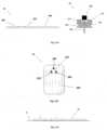
- Figures 1A-1Cshow connection of the patch unit (10) to and disconnection of the patch unit (10) from the needle unit (20).
- Figure 1Ashows the needle unit (20) being attached to the body. In Fig. 1A are seen also, the cradle (300) and the well (310). After attaching the needle unit (20) to the body, the user may connect the patch unit (10) to the needle unit (20) by connecting the patch unit housing to the cradle and the exit port (not shown) of the patch unit to the well (310).
- Figure 1Bshows the patch unit (10) and the needle unit (20) being connected and attached to the patient body. The patch unit (10) and needle unit (20) after connection together constitute a fluid delivery device.
- Figure 1Cshows disconnection of the patch unit (10) from the needle unit (20). The process of connection and disconnection can be repeated many times according to the patient's discretion or as otherwise necessary.
- Figures 2A-2Eshow schematically two units of the fluid delivery device, the patch unit (10) and the needle unit (20).
- Figure 2Ashows the two units, the patch unit (10) and the needle unit (20).
- Figure 2Bshows the needle unit (20) adhered to the skin (5).
- Figure 2Cshows connection of the two units.
- Figure 2dshows the two connected units brought into operation mode, and Figure 2E shows disconnection of units. The two units can be repeatedly connected and disconnected.
- FIGS 3A-3Bshow the patch unit (10) in more detail.
- the patchhas on its lower surface an exit port (210).
- the patch unit (10)can be composed of a single part ( fig. 3A ) or of two parts ( fig. 3B ).
- the two part patch unit (10)is composed of a reusable part (100) and a disposable part (200) with an exit port (210).
- the exit port (210)allows fluid dripping during priming and fluid communication with the needle unit (20) during operation.
- Figures 4A-4Bshow an arrangements of the patch unit (10) employing a peristaltic pump as a pumping mechanism for dispensing fluid to a patient body.
- Figure 4Ashows a single-part patch unit (10) which is not part of the presently claimed invention.
- the fluidis delivered from a reservoir (220) provided in the patch unit (10) through a delivery tube (230) to the exit port (210).
- the peristaltic pumpcomprises a rotary tooth wheel (110) provided with rollers and a stator (290).
- Driving mechanism (120)is provided (e.g. a stepper motor, a DC motor, a SMA actuator or the like), which rotates the rotary wheel and is controlled by electronic components residing in the patch unit (10).
- electronic componentscan be controller, processor and/or transceiver.
- the electronic componentsare schematically designated by a common numeral (130).
- An appropriate energy supply means (240)is also provided, which may include one or more batteries.
- Infusion programmingcan be carried out by a remote controller (not shown) having a bidirectional communication link with the transceiver provided in the patch unit (10).
- the infusion programmingcan be carried out by manual buttons/switches (105) provided on the patch unit (10).
- Figure 4Bshows a two-part patch unit (10) comprised of a reusable part (100) and a disposable part (200).
- Reusable part (100)may comprise positive displacement pump provided with rotary wheel (110), driving mechanism (120) and/or electronic components (130).
- Disposable part (200)may include a reservoir (220), delivery tube (230), energy supply means (240), exit port (210) and/or stator (290). Fluid dispensing is possible after connecting the reusable part (100) with disposable part (200). This arrangement is described in USSN 11/397,115 .
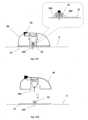
- Figures 5A-5Cshow the needle unit (20).
- Figure 5Ashows the needle unit (20) before insertion.
- the needle unit (20)comprises the following components: a cradle (300), a cannula (330), a penetrating member (320) and a well (310).
- Fig 5Bshows the needle unit (20) after it has been adhered to the skin (5).
- the cradle (300)is adhered to the skin (5) by virtue of adhesive layer, which is provided on the side of the cradle (300) that faces the skin (5).
- the cannula (330) and the penetrating member (320)are shown after they have been placed in the subcutaneous compartment of the patient's body.
- Fig 5Cshows a still further step, when the needle unit (20) remains adhered to the skin (5) and the cannula (330) remains within the subcutaneous compartment while the penetrating member (320) is being removed.
- FIGS 6A-6Cshow additional details of the needle unit (20): a cross sectional view (6A), an upper view (6B) and a perspective view (6C).
- the cradle (300)is configured as a flat and thin resilient sheet and it can be made for example from a polymer sheet having thickness of about 0.8 mm.
- the cradle (300)may be configured to any desired shape suitable for connection to the patch unit (10).
- To the bottom side of the cradle (300) that faces the skin (5)can be attached an adhesive tape (i.e. 3M TM Soft, conformable aperture non-woven cloth tape) or this bottom side can be coated with a biocompatible epoxy layer enabling adherence to the skin (5).
- adhesive tapei.e. 3M TM Soft, conformable aperture non-woven cloth tape
- a protrusionextends upwardly from the cradle (300) and forms the well (310).
- the well (310)may be positioned at the center, corner or any other location of the cradle (300).
- the upper end of the well (310)comprises a well inlet port (311), and the lower end of the well (310) comprises an outlet port (312) through which the cannula (330) is attached to the cradle (300).
- the inlet port (311)is sealed with a septum (313) that can be made of any self-sealable material (i.e. silicon rubber).
- the septum (313)can be pierced many times by a connecting lumen (250) provided in the patch unit (10) as will be described in greater detail below with reference to Figure 17 .
- the septum (313)keeps the well (310) sealed after withdrawal of the penetrating member (320) as shown in Figure 7 .
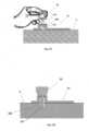
- Figures 7A-7Dshows how the needle unit (20) is attached to the body of a patient.
- the attachment procedureincludes insertion of the cannula (330) and subsequent adherence of the cradle (300) to the skin (5).
- Fig. 7Ashows the needle unit (20) before attachment.
- the needle unit (20)includes cannula (330), cradle (300), well (310) and penetrating member (320).
- the penetrating member (320)includes a penetrating dagger (321) having a sharp tip (322) and a grip portion (323).
- the penetrating member (320)punctures the self-sealable septum (313) and displaces the cannula (330) towards the skin (5) while the sharp tip (322) pierces the skin (5) and the cannula (330) penetrates the subcutaneous compartment under the skin surface.
- Fig 7Bshows the needle unit (20) before insertion, i.e. just before the penetrating member punctures the skin and the cannula penetrates the subcutaneous compartment.
- Fig. 7Cshows the needle unit (20) after insertion.
- the cradle (300)is adhered to the skin (5) and the cannula (330) and penetrating member (320) are subcutaneously inserted.
- Fig. 7Dshows the needle unit (20) adhered to the skin (5) and the penetrating member (320) removed from the needle unit (20). The well remains to be sealed by the septum (313) after penetrating member (320) withdrawal.
- the needle unitcan be attached to the skin automatically by means of an inserter.
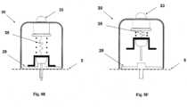
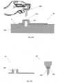
- Figures 8A-Fshow an automatic insertion of the needle unit (20) by using an inserter (30) which is not part of the presently claimed invention.
- the inserter (30)has a cup-shaped body.
- the inserter (30)comprises a cup-shaped body portion (31), an actuation mechanism (32) e.g. an actuator, an activation button/trigger (33) and a spring biased plunger element (34).
- the needle unit (20)is fully concealed within the inserter's body portion (31).
- Figure 8Bshows how the inserter (30) is located on the skin (5) before insertion. By triggering the activation button/trigger (32) the needle unit (20) is fired towards the skin (5).
- Figure 8Cshows the needle unit (20) being fired and attached to the skin upon triggering the activation button/trigger (33).
- Figure 8Dshows withdrawal of the inserter (30), while leaving the needle unit (20) in place.
- Figures 8E-Fshow an alternative arrangement, in which penetrating member (320) is being automatically withdrawn from the needle unit (20). In this arrangement the inserter is provided with a retraction spring (35), which retracts the penetrating member (320).
- Figure 8eshows the needle unit (20) placement following button/trigger (33) depression.
- the retraction spring (35)is extended.
- Figure 8fshows penetrating member (320) withdrawal by the retracted spring (35), leaving the needle unit (20) in place.
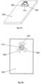
- FIGS 9A-9Bshow the cradle (300) provided with the well portion (310) protruding therefrom and sealed by a septum (313).
- the cradle (300)is provided with arcuate discrete slits (305) formed on the cradle's upper face and surrounding the well portion (310).
- FIG 10Ashows the needle unit (20) comprising cradle (300) with the penetrating member (320) inserted within the well portion (310). Now, the needle unit (20) is ready for loading into inserter.
- FIG 10Bis shown how the needle unit (20) is loaded into inserter (40) which is not part of the presently claimed invention. It is seen that the inserter is provided with legs (45) which are intended for entering into slits (305).
- Figure 10Bshows the inserter with needle unit (20) loaded therein ready for firing towards the skin (5). By triggering the activation button/trigger (43) the needle unit (20) can be fired towards the skin (5).
- Figure 10Cshows the needle unit (20) being fired and attached to the skin (5) upon triggering the activation button/trigger (43).
- Figure 10Dshows automatic withdrawal of the inserter (40) including penetrating member (320), while leaving the needle unit (20) in place.
- cradle (300)is configured as a flat and thin resilient sheet having thickness of about 0.8 mm, it may be difficult to prevent crumpling of the cradle (300) and ensure a uniform horizontal spreading of the cradle surface, which is crucial for a reliable adherence of the cradle (300).
- Figure 10Eshows an arrangement of the needle unit (20) provided with a few strips (47) which prevent crumpling (i.e., crumpling prevention means) of the cradle surface during firing of the needle unit (20). The strips (47) are connected by their one end to the grip portion (323) of the penetrating member (320).
- the strips (47)are slightly adhered to the cradle (300) by glue and are spread across the upper surface of the cradle (300). It is preferable if the strips (47) are located between adjacent arcuate slits (305). The width, thickness and rigidity of the strips (47) are selected to ensure that the cradle (300) remains in horizontal position during firing and does not crumple.
- Figure 10Fshows the needle unit (20) provided with strips (47) and being loaded within the inserter (40). It is seen that legs (45) pass through slits (305). Strips (47) ensure spreading of the cradle (300) without crumpling.
- Figure 10Gshows the next step in which the inserter (40) is withdrawn. The strips (47) disconnect from the cradle (300) and remain attached to the grip portion (323) when the inserter is evacuated from the cradle (300).
- Figs. 11A-11Fshow another arrangement of the needle unit.
- the needle unitcomprises two parts as follows:
- Fig. 11Ashows the two parts of the needle unit (20) before insertion - the penetrating cartridge part (22) and the cradle part (21).
- the cradle part (21)comprises the cradle base (300) and connecting latches (306), which are situated around an opening made in the cradle base (300).
- the penetrating cartridge part (22)comprises well portion (310), lateral recesses (316) made in the well portion, septum (313), cannula (330) and penetrating member (320).
- the amount of recesses and their locationshould allow snapping of the latches on the recesses when the penetrating cartridge part (22) approaches the cradle part (21).
- Fig 11Bshows an upper view of the cradle part (21) including cradle base (300) and three connecting latches (306), which are situated symmetrically around the opening (307).
- Fig 11Cshows the cradle part (21) attached to the patient skin (5). The attachment can be achieved by gluing with adhesives or by other means known in the art. It will be appreciated that an adhesive layer should be put on that side of the cradle base, which faces the skin.
- Figure 11Dshows how the penetration cartridge part (21) is approaching the cradle part (21) and latches (306) are about to snappingly engage the recesses (316). Upon engagement the sharp tip (322) of the penetrating member pricks skin (5) and cannula (330) penetrates the body.
- Figure 11Eshows the penetration cartridge part (22) connected to the cradle part (21).
- Figure 11Fshows the removal of the penetrating member (320) from the penetrating cartridge part (22).
- the cradle part (21)remains adhered to the skin (5) and the cannula (330) remains in the body.
- the self-sealable septum (313) of the well portion (310)allows for repeated connection/disconnection of the connecting lumen of the patch unit (10) and prevents leaking and penetration by contaminants, as shown in Figure 17 .
- FIGs 12A-12Dshow an arrangement of an inserter (50) (which is not part of the presently claimed invention) for use with the two part needle unit (20).
- the inserterfacilitates adhesion of the cradle part (21) to the skin (5) and allows automatic connection of penetrating cartridge part (22) with the base cradle part (21).
- the cradle base part (21)is first attached to the skin and consecutively cartridge part (22) is fired by the inserter (50) toward the cradle base part (21) so as to connect the cradle base part (21) with the penetrating cartridge part (22).
- Fig. 12Ashows inserter (50) and the two part needle unit (20) that comprises cradle part (21) and penetrating cartridge part (22).
- the figureshows the situation before insertion.
- the inserter (50)is provided with an actuation mechanism (52) employing plunger-spring element (54) and actuation button/trigger (53).
- the inserteris loaded with penetrating cartridge part (22).
- the penetrating cartridge part (22)comprises well portion (310), cannula (330) and penetrating member (320).
- the cradle part (21)comprises cradle base (300) which upper side is relatively glued (or otherwise secured) to the inserter's bottom side.
- Figure 12Bshows the cradle part (21) attached to the patient skin (5). The attachment can be done by adhesives or by other means known in the art. Adherence is ensured by pressing the inserter (50) toward the skin.
- Fig. 12Cshows the inserter (50) after the actuation button/trigger (53) is pressed and the penetrating cartridge part has been fired. Upon firing the penetrating cartridge part (22) is connected to the cradle part (21) by virtue of snapping engagement between latches (306) and depressions (316) made on the well portion (310) of the penetrating cartridge part (22).
- Figure 12Dshows still further step, when the inserter (50) along with the penetrating member (320) is being automatically removed from the skin (5).
- the cradle part (21)remains stay adhered to the skin (5) and the cannula (330) remains inserted within body.
- Figs. 13A-13Gshow another arrangement of a needle unit (20) which is intended for manual insertion mode.
- the needle unit (20)also comprises two parts as follows:
- Fig. 13Ashows the two parts before insertion.
- the cradle part (21)comprises cradle base (300) and well portion (310).
- the penetration cartridge part (22)comprises cannula (330), penetrating member (320) and septum (313).
- Figure 13Bshows the cradle part (21) after it has been attached to the patient skin (5). The attachment can be done by adhesives or by other means known in the art.
- Figure 13Cshows manual insertion of the penetration cartridge (22) through the well portion (310).
- the septum (313)is pierced by the dagger (321).
- Figure 13Dshows sharp tip of the dagger (322) and the cannula (330) within the subcutaneous tissue.
- Figure 13Eshows the removal of the penetrating member (320).
- the cradle part (21)remains adhered to the skin and the cannula (330) remains in the body.
- the self-sealable septum (313) of the well portion (310)prevents leaking of the therapeutic fluid as well as contamination.
- Fig. 13Fshows another arrangement of the penetration cartridge part (22). In this arrangement the septum (313) is attached to the cannula (330) and is introduced into the upper side of the well portion (310) during insertion of the penetrating cartridge (22) through the well portion (310).
- Fig. 13Gshows another arrangement of the cradle part (20). In this arrangement the well portion (310) is in a tilted position allowing the insertion of the penetrating cartridge part (22) at an angle with respect to the skin.
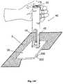
- FIGs 14A-14Fshow another arrangement of an inserter (which is not part of the presently claimed invention) for use with a two part needle unit.
- the inserter (60)is used for the insertion of the cartridge part (22) into the cradle base part (21).
- the cradle part (21)is first manually attached to the skin (5) and consecutively the penetrating cartridge part (22) is automatically inserted by the inserter (60).
- Fig. 14Ashows the inserter housing (60) and the penetrating cartridge part (22) before insertion.
- Figure 14Bshows the cradle part (21).
- the inserter housing (60)accommodates actuation mechanism (62), spring-loaded plunger element (64) and the penetration cartridge part (22).
- the penetrating cartridge part (22)comprises cannula (330) and penetrating member (320).
- the cradle part (21)comprises cradle (300) and well portion (310).
- Figure 14Cshows the cradle part (21) attached to the patient skin (5). The attachment can be done by adhesives or by other means known in the art.
- Figure 14Dshows the inserter housing (60) put on the well portion (330) of the cradle part (21).
- Fig. 14Eshows the penetrating cartridge (22) after penetrating the skin (5) such that the cannula (330) has penetrated within the subcutaneous tissue.
- Figure 14Fshows the removal of the penetrating member (320).
- the cradle part (21)remains adhered to the skin (5) and the cannula (330) remains in the body.
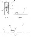
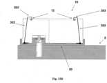
- FIG 15shows still another arrangements of the patch unit (10) that is composed of a single part, which is not part of the presently claimed invention.
- the patch unit (10)contains housing (11), which is provided with exit port (210), through which protrudes a short connecting lumen (250) having sharpened forward end.
- the opposite rear end of the lumenis in fluid communication with the delivery tube (230) and reservoir (220).
- the sharpened end of the lumen (250)enters in the cannula (330) to provide fluid communication between the cannula (330) and reservoir (220).
- the connecting lumen (250)is rigidly secured within the exit port (210). It is connected by its rear end to the tube (230) through a connector (251).
- the housing (11)is provided with lateral notches (12).
- the sharpened forward end of the connecting lumen (250)pierces the septum (313) of the needle unit (20) and enters in the cannula (330).
- the lateral notches (12)allow connecting of the patch unit (10) to the needle unit (20).
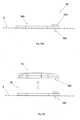
- FIG 16shows an embodiment of the patch unit (10) composed of two parts.
- a reusable part (100)contains components that can be used multiple times while disposable part (200) contains disposable components including reservoir (220) and exit port (210). The disposable components are used until emptying of the reservoir (220).
- the connecting elemente.g., connecting lumen
- Lateral notches (12)are provided on exterior sides of both parts.
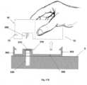
- FIGS 17A-17Fshow an example of connection and disconnection of the patch unit (10) and the needle unit (20).
- Fig. 17Ashows the two units before connection.
- the needle unit (20)is attached to the user skin (5) and the cannula (330) penetrates within the subcutaneous tissue.
- the patch unit (10) in this exampleis composed of two parts and contains lateral notches (12), exit port (210) and connecting lumen (250).
- the needle unit (20)contains cradle (300), cannula (330), anchoring latches (302), well portion (310) and well septum (313). When the patch unit (10) is brought into contact with the needle unit (20) it is guided by the anchoring latches (302) maintaining precise alignment between the two units and anchoring of the two units.
- Figure 17Bshows the patch unit (10) after is has been connected to the skin-adhered needle unit (20) and secured due to snapping engagement of the anchoring latches (302) provided at the outside periphery of the needle unit (20) with the lateral notches (12) provided at the patch unit (10).
- FIG. 17Cshows the patch unit (10) being disconnected by back-pulling the elastically deformable latches (302).
- Figure 17dshows the patch unit (10) disconnected from the needle unit (20) which remains adhered to the skin (5) and the cannula (330) remains in the body.
- the self-sealable septum (313)prevents body fluids from leaking and also prevents contamination.
- the cradle (300)could be protected to avoid contamination and abrasion of protruding elements by a protective cover (280), as shown in figures 17E-17F .
- the protective cover (280)can be configured as a convex - shaped rigid polymeric cover which conceals the cradle (300) within. Thus, the cradle (300) when covered is not exposed to the environment. The protective cover (280) should be removed before reconnection of the patch unit (10).
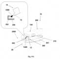
- FIGs 18A-18Kshows another embodiment of a fluid delivery device that includes a patch unit and a needle unit.
- the patch unit (10)comprises two parts - reusable part (100) and disposable part (200).
- the disposable partis provided with the exit port (210) which is located not in the center of the disposable part (200) but close to its lateral side.
- Figure 18Ashows the two parts.
- the disposable part (200)has a U-shape configuration and the reusable part (100) has a squared configuration mating the recess in the U-shaped disposable part (200).
- the reusable part (100)is fitted with driving mechanism (110), with pumping mechanism (120) e.g. a peristaltic pump and with suitable electronics (130).
- the disposable part (200)is fitted with reservoir (220), with power supply means (240), with delivery tube (230) and with connecting lumen (250).
- the tube (230)is connected by its one end to the reservoir (220) and by its opposite end to the connecting lumen (250).
- the connecting lumen (250)resides within the exit port (210).
- FIG. 18B and 18Cit is shown how reservoir (220) is being filled and priming is carried out.
- the filling and the primingare carried out by a syringe connectable to the reservoir (220).
- Connection of the syringe to the reservoirmay be also carried out by means of a dedicated adapter, examples of which are described in more detail in commonly owned application USSN 60/838,660 .
- the adapterallows connection of the filling syringe to the reservoir (220).
- Figure 18Dshows the patch unit (10) assembled after the reusable part (100) and the disposable part (200) are connected. Upon connection, air is purged out of the reservoir (220), out of the tube (230) and out of the connecting lumen (250).
- Figure 18Eshows the reusable part (100) and the disposable part (200) before they are connected.
- Figure 18Fshows another view of the patch unit (10) after connecting the two parts.
- Figure 18gshows the needle unit (20) before its adherence to the skin.
- the needle unit (20)comprises cradle (300), well portion (310) and cannula (330).
- Figure 18Hshows the needle unit (20) after it has been adhered to skin (5).
- Figure 18Ishows connection of patch unit (10) to needle unit (20);
- Figure 18Jshows both units being connected (operation mode) and
- Figure 18Kshows the units being disconnected.
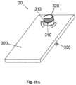
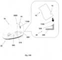
- FIGs 19A-19Dshow another embodiment of a fluid delivery device and a method for connecting a patch unit (10) and a needle unit (20).
- the patch unit (10)comprises a reusable part (100) and a disposable part (200).
- the needle unit (20)comprises a cradle (300) having an elevated peripheral wall (301), well portion (310) and adhesive layer at the lower surface of the cradle.
- Figure 19Ashows the first step of connecting the patch unit (10) to the needle unit (20) by moving the patch unit (10) towards the needle unit (20) along arrow (1000), such that a protrusion (12) in the cradle (300) engages with a corresponding recess (302) provided on the rear end (2000) of the cradle (300) (or vice versa).
- Figure 19Bshows the next step of connecting the two units by pivoting the front end (3000) of the patch unit (10) towards the needle unit (20) along arrow (1100).
- the connectionis carried out by snapping engagement of a latch (304) in the cradle (300) with a corresponding notch (14) in the patch (10).
- Figure 19Cshows the device in an operation mode after the patch (10) and the needle (20) units have been connected.
- the patientcan conveniently use the device since connecting and disconnecting of the patch unit (10) and the needle unit (20) does not affect the use of the device.
- the patientcan give an insulin bolus dose by pressing simultaneously the two buttons/switches (15) provided at the lateral walls of the reusable part (100).
- Figure 19Dshows disconnection of the units by the release of a latch (304), pulled along the arrow (1300).
- the patch unit (10)now may be withdrawn by pivoting it along the arrow (1200).
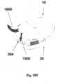
- FIGs 20A-20Dshows another embodiment of a fluid delivery device and a method for connection the patch unit (10) and the needle unit (20).
- the patch unit (10)comprises a reusable part (100) and a disposable part (200). There is provided an exit port (210) in the disposable part (200).
- the needle unit (20)comprises a cradle (300) having an elevated side wall (301), a well portion (310) and adhesive layer at the lower surface of the cradle.
- Figure 20Ashows patch unit (10) and needle unit (20) being connected by a sliding movement of the patch unit (10) towards the cradle (300) along arrow (1400).
- Figure 20Bshows operation mode of the device after the patch unit (10) has been connected to the needle unit (20).
- Patientcan control insulin bolus dose by using the remote controller or by pressing simultaneously on the two buttons/switches (15).
- Figure 20Cshows the connection of the exit port (210) with well portion (310) therefrom introducing the connecting lumen (250) into the well portion (310).
- Connection by slidingrequires horizontally directed connecting lumen (250) on the patch unit (10) and a lateral inlet port (311) on the well portion (310).
- the self-sealable septum (313)is provided for the penetrating member insertion. This septum (313) seals the well portion (310) and it is oriented horizontally.
- an additional self-sealable septum (315)which is directed vertically. This septum is provided for penetrating of the connecting lumen (250).
- Figure 20Dshows the connecting lumen (250) which pierces the well's septum (313) allowing fluid communication with the reservoir.
- Figure 20Eshows disconnection of patch unit (10) from needle unit (20) by releasing the latch (304) along arrow (1500) followed by the sliding withdrawal of the patch unit (10) along arrow (1600).
- FIGS 21A-21Cshow another embodiment of a fluid delivery device and a method for connecting a patch unit (10) and a needle unit (20).
- the patch unit (10)comprises a reusable part (100) and a disposable part (200).
- the patch unit (10)is provided with elastically deformable latches (16) provided at the periphery of the patch unit (10).
- the needle unit (20)comprises a cradle (300) and a well portion (310).
- Notches (17)are provided at the periphery of the cradle (300).
- the notches (17)are configured to mate the latches (16), such that snapping engagement is possible therebetween.
- the peripheral wall (2100) of the patch unit (10)is elastically deformable, such that latches (16) can be easily pressed inwardly.
- Figure 21Ashows the two units are being brought together and are about to be connected by virtue of snapping engagement of latches (16) with notches (17).
- Fig. 21Bshows patch unit (10) secured on the cradle (300) by virtue of snapping of the latches (16) on notches (17).
- Fig 21Cshows disconnection of patch unit (10) by squeezing the wall of the patch unit (10) such that latches (16) are elastically displaced inwardly to allow their disengagement from the notches (17).
- FIGs 22A-22Cshow another embodiment of a fluid delivery device and of a method for connecting a patch unit (10) and a needle unit (20).
- the patch unit (10) and the needle unit (20)are connectable by virtue of magnetic forces.
- the patch unit (10)comprises a reusable part (100) and a disposable part (200).
- the needle unit (20)comprises a cradle (300) and a well portion (310).
- Fig. 22Ashows patch unit (10) being brought to the needle unit so as to connect it to the needle unit (20).
- Magnetic strips (18)are provided at several locations of the bottom surface of the patch unit (10).
- Magnetic strips (28)are provided at corresponding locations of the upper side of the cradle (300).
- Cradle (300)is configured with supporting walls (302) protruding upwardly and parallel to the outside surface of the well portion (310).
- the exit port (210) of the patch unit (10)is configured to match the periphery of the wall portion (310).
- Figure 22Bshows that connection between the two parts is maintained by magnetic attraction forces of the magnetic strips (18) and (28).
- Fig. 22Cshows disconnection of patch (10) from needle unit (20). This may be affected by placing a thin separating means (9) such as a coin or pin within a dedicated recess (19) provided at the patch unit (10).
- connectionmay be achieved by using any other suitable connective material instead of magnetic strips, such as Velcro ® Adhesives (e.g., comprising hooks and loops), or the like.
- FIGS 23A-23Eshow another embodiment of a fluid delivery device and of a method for connecting a patch unit (10) and a needle unit (20).
- the patch unit (10)is securable on the needle unit (20) by virtue of a trap-like mechanism (an example of which is described below), which, according to some embodiments, is (for example) a structure utilizing one or more catches/recesses/grooves to receive corresponding swing arms (arms) -- at least a portion of the swing arm is captured by a corresponding groove thereby "trapping" the patch within the cradle.
- the patch unit (10)comprises a reusable part (100) and a disposable part (200).
- the needle unit (20)comprises a cradle (300) and a well portion (310). Swiveling arms (302) terminated by hooked ends (303) are provided on the needle unit (20) and corresponding grooves (12) are provided on the patch unit (10).
- Figure 23Ashows connection of patch unit (10) and needle unit (20) by arms (302).
- Figure 23Bshows patch unit (10) being secured by arms (302) which have been swiveled so as the hooked ends (303) have entered within the grooves (12, 303) in order to lock the patch unit on the cradle.
- Fig. 23Cshows disconnection of patch (10) by swiveling the arms (302) until the hooked ends (303) exit the grooves (12) and release the patch unit (10).
- Figures 23Dshows perspective view of the patch unit (10) being released and disconnected from the cradle.
- Figure 23Eshows perspective view of the patch unit (10) secured on the cradle (300).
Landscapes
- Health & Medical Sciences (AREA)
- Heart & Thoracic Surgery (AREA)
- Animal Behavior & Ethology (AREA)
- General Health & Medical Sciences (AREA)
- Biomedical Technology (AREA)
- Engineering & Computer Science (AREA)
- Hematology (AREA)
- Life Sciences & Earth Sciences (AREA)
- Veterinary Medicine (AREA)
- Anesthesiology (AREA)
- Public Health (AREA)
- Vascular Medicine (AREA)
- Dermatology (AREA)
- Pulmonology (AREA)
- Infusion, Injection, And Reservoir Apparatuses (AREA)
- Medicinal Preparation (AREA)
- Media Introduction/Drainage Providing Device (AREA)
- Medicines That Contain Protein Lipid Enzymes And Other Medicines (AREA)
Description
- Embodiments of the present invention relate generally to a device for sustained medical infusion of fluids to a patient's body and for connecting and disconnecting the device to and from the patient's body. More particularly, some embodiments of the present invention relate to a new configuration of a portable infusion patch-like device that can be disconnected from and reconnected to the patient's body as necessary or according to the patient's discretion.
- Medical treatment of some illnesses requires continuous drug infusion into various body compartments, which is carried out as subcutaneous and intra-venous injections. For example, diabetes mellitus patients require the administration of varying amounts of insulin throughout the day to control their blood glucose levels. In recent years, ambulatory portable insulin infusion pumps have emerged as a superior alternative to multiple daily injections of insulin. These pumps, which deliver insulin at continuous basal rates as well as in bolus volumes, were developed to liberate patients from repeated self-administered syringe injections, and allow them to maintain a near-normal daily routine. Both basal and bolus volumes must be delivered in precise doses, according to individual prescription, since an overdose of insulin could be fatal. Therefore, insulin injection pumps must feature high reliability, to prevent the unintentional delivery of an excess of insulin.
- Several ambulatory insulin infusion devices are currently available on the market. Mostly, these devices have two parts: a durable portion, containing a pumping mechanism, a controller and electronics, and a disposable portion containing a reservoir, a needle/penetrating assembly (e.g., a cannula and penetrating/needle member), and a fluid delivery tube altogether referred to as the "infusion set". Usually, the patient fills the reservoir, attaches the infusion set to the exit port of the reservoir, and then inserts the reservoir into the pump housing. After purging air out of the reservoir, out of the tube and out of the needle, the patient inserts the needle assembly, penetrating member and cannula, at a selected location on the body, and withdraws the penetrating member while leaving the cannula within the body. To avoid irritation and infection, the subcutaneous cannula must be replaced and discarded after two to three days, together with the empty reservoir.
- Examples of a first generation pump, which employs disposable syringe-type reservoir and tubes, were described in
1972, by Hobbs, in U.S. Patent No. 2,631,847 , and in1973, by Kaminski, in U.S. Patent No. 3,771,694 , and later byJulius, in U.S. Patent No. 4,657,486 , and bySkakoon, in U.S. Patent No. 4,544,369 . The driving mechanism employed in these devices comprises a screw thread derived plunger controlling the programmed movement of a syringe piston. While these devices represent an improvement over multiple daily injections, unfortunately they are heavy, bulky, and must be carried in a pocket or attached to a belt. Consequently, the fluid delivery tube is long, usually more than 60 cm, to permit needle insertion in remote sites of the body. Furthermore, since the tubing is long and not discreet, this severely disturbs teenagers' body image and prevents the teenager patients from insertion in remote sites like buttocks and limbs. To avoid the tubing limitations, a second generation of insulin pump was devised, namely - skin adhered pumps. For the sake of brevity these pumps will be referred-to further as patch type pumps or simply patches. - These patches include a housing having a bottom surface adapted for contact with the patient's skin, a reservoir disposed within the housing, and an injection needle which is in fluid communication with the reservoir. These skin adhered devices should be disposed every 2-3 days like current pump infusion sets. This type of pump was described by
Schneider, in U.S. Patent No. 4,498,843 ,Burton in U.S. Patent No. 5,957,895 ,Connelly, in U.S. Patent No. 6,589,229 , and byFlaherty in U.S. Patents No. 6,740,059 . Additional configurations of skin adhered pumps are disclosed inU.S. Patent Nos. 6,723,072 and6,485,461 . In these configurations, the pump is adhered to the patient's skin for the entire time period of device usage and the needle emerges from the bottom surface of the device and is fixed to the device housing. - These second-generation skin adhered devices have several limitations:
- Disconnection and reconnection of the pump to the patient is impossible -while there exists several conditions such as hot showers, bath and sauna (cause insulin denaturation) as well as other activities during which disconnection of the pump is required. In some cases the patient wants to disconnect the pump for a short period and subsequently reconnect it just to free himself from the 24 hours a day / 7days a week life long connection.
- Waste of Insulin - In cases of site misplacement (scar tissue, bleeding, cannula kinking etc.) the entire device including reservoir, which is full of insulin should be disposed.
- These devices are expensive - the entire device including relatively expensive parts should be disposed every pump replacement. Thus the production cost is high and the final product price far exceeds Medicare allowable payments.
- These devices are bulky and heavy -The automatic insertion mechanism included within the device occupies substantial volume as described in
U.S. Patent No. 6,699,218 , which is incorporated by reference herein. The patient must carry the heavy and bulky insertion mechanism during the entire usage of the pump. - In view of the foregoing, what is needed is an improved method and device for delivery of therapeutic fluid to the body.
WO 2006/108809 relates to a medical skin mountable device, and discloses a medical device in the form of a modular skin-mountable drug delivery device comprising a patch-like needle unit and a reservoir unit. One arrangement of the medical device has a modular design comprising a durable control unit adapted to be mounted ona reservoir unit comprising a reservoir and an expelling assembly controllable by the control unit through contacts. The reservoir unit is configured to be secured to a transcutaneous device to provide fluid communication between the reservoir and the transcutaneous device.WO 02/094352 - In accordance with the present invention, there is provided a therapeutic infusion system as defined in appended
independent claim 1. Embodiments of the present invention are defined in appended claims dependent onindependent claim 1. Methods of using the therapeutic infusion system are presented to help better understand the present invention, but do not form part of the present invention. The terms "system" and "apparatus" can be used interchangeably in some embodiments of the present invention. In some embodiments, a miniature portable programmable fluid dispensing patch type pump is provided that does not have long external tubing and can be attached to the patient at any desired location on the patient's body. Alternatively or additionally, the device allows for disconnection and reconnection to the patient to make possible temporary removal by the patient in cases such as hot bath, sauna, etc. Such disconnection and reconnection can be performed without harm various components of the patch, like the dispenser, the needle, nor the surrounding tissue and/or the patient. The device may be inserted into position manually, automatically, or based on a combination of manual and automatic means. - It is worth noting that the term "patch" according to embodiments of the present invention, may be understood to be a small sized infusion system/device, which is directly adherable to a user's (human body) skin. For example, in some embodiments, the "patch" is a credit card sized infusion device, with a thickness of between about 5 mm to about 25 mm in thickness, and preferably less than about 15 mm in thickness.
- In some arrangements, the fluid delivery device comprises 3 units: a dispensing patch unit, a skin adherable unit and a remote control unit. The patch unit is connectable to and disconnectable from a skin adherable needle unit, and a remote control unit is capable of programming and data acquisition. Remote control unit, according to some arrangements, includes any electronic unit that can include functionality for communication with the patch/infusion device, and may include watches, mobile telephones, personal computers, and the like.
- Below is a description of each unit according to some arrangements:
- 1. Patch unit: comprising a driving and pumping mechanism (either separately provided or integral with one another), a reservoir and an exit port. The exit port allows connection of the patch unit to and disconnection from the needle unit. The exit port is provided with a small connecting lumen that can pierce a self sealable rubber septum. The connecting lumen allows fluid communication between the patch unit and the needle unit. The patch unit comprises two or more parts. In this configuration it may contain:
- a. Reusable part - contains the driving and pumping mechanism(s), electronics and other relatively expensive components e.g. an occlusion sensor.
- b. Disposable part - contains components such as the reservoir, tubes and batteries that can last until reservoir emptying, usually a few days.
- 2. Needle unit comprises the following :
- a. Cannula and penetrating member. The penetrating member is removed after insertion.
- b. Cradle: a flat sheet with an adhesive layer (and/or one portion of a hook and loop fastening system - e.g., Velcro®) facing the skin and with a connecting means on its upper side allowing connection and disconnection of the patch unit. Upon insertion of the cannula the cradle remains connected to the skin by virtue of adhesive layer. The cradle anchors the cannula and allows connection to the patch. The cradle can be integral with the cannula and well or it can be separate, a stand alone piece.
- c. Well: a tubular protrusion emerging upwardly from the cradle to allow alignment with the patch unit and appropriate connection between the needle and the patch unit as required for proper fluid delivery to the body.
- 3. Remote control unit comprising means (e.g., electronics, including a CPU) and one-way or two-way communication elements for wirelessly communicating with the patch unit) required for issuing instructions for programming fluid flow and for data acquisition.
- It is worth noting, that the cradle, according to some arrangements, may be any structure which is adherable to a user of a medical device, and which can receive a medical device, and retain it so that it may be used by the user in its intended manner. Accordingly, in some arrangements, such a cradle (as described with reference to some of the embodiments of the invention described herein) allows repeated connection and disconnection of the medical device to/from the cradle, even while the cradle remains adhered to the user. Moreover, according to some arrangements, the cradle may be simply a substantially flat structure having a portion/side which includes adhesive to adhere the cradle to the user's skin (and, thus, retain/hold the medical device in position), and having a portion/side which is faces/lies-adjacent to the medical device. According to other arrangements, the cradle may also be a housing (e.g., "box" like structure having at least one opening to receive the medical device). For example, the housing may be a box, having a side which is substantially flat (or configured to the natural contour of a surface of the body), and which also includes a side which is capable of being open to (for example) slidably receive the medical device.
- Some arrangements of the present disclosure are directed to a therapeutic fluid infusion device cradle adherable to the skin of a user for retaining a therapeutic fluid dispenser for delivering a therapeutic fluid to a user. In such arrangements, the cradle includes a structure having a first surface configured for adhering to the skin of a user and having at least a portion of a second surface which substantially corresponds to at least a portion of a therapeutic fluid infusion device, at least one connecting area for connection with a corresponding connecting area of the infusion device, wherein connection between the two connecting areas enables the cradle and infusion device to be removably affixed to one another, an opening for receiving a fluid dispensing outlet of the infusion device and for receiving a cannula through which therapeutic fluid is delivered to the user, and an adhesive provided on at least a portion of the first surface of the cradle for adhering the cradle to the user.
- Some arrangements of the present disclosure are directed to a therapeutic fluid infusion system for delivering a therapeutic fluid to a human body. The system includes a first assembly having a cradle configured for adhesion to a cutaneous region of the human body, a cannula, and a self-sealing septum, wherein a distal portion of the cannula is configured for subcutaneous placement within the human body and wherein the self-sealing septum separates a proximal portion of the cannula from an external environment. The system also includes a second assembly configured for removable attachment to the first assembly, where the second assembly includes a pump, a reservoir for containing a therapeutic fluid, and a connecting lumen configured to penetrate the self-sealing septum in order to place the second assembly in fluid communication with the first assembly.
- Some parts of the present disclosure are directed to a method for delivering a therapeutic fluid to a human body, where the method includes securing a first assembly to a cutaneous region of the human body, penetrating the cutaneous region in order to place the first assembly in fluid communication with the human body, removably attaching a second assembly comprising the therapeutic fluid to the first assembly in order to place the second assembly in fluid communication with the first assembly, detaching the second assembly from the first assembly and substantially simultaneously with the detaching, sealing the first assembly to prevent fluid communication between the human body and an outside environment.
- Some arrangements of the present disclosure are directed to an apparatus for delivering a therapeutic fluid to a human body, the apparatus including means for securing a first assembly to a cutaneous region of the human body, means for penetrating the cutaneous region in order to place the first assembly in fluid communication with the human body, means for removably attaching a second assembly comprising the therapeutic fluid infusion device to the first assembly in order to place the second assembly in fluid communication with the first assembly, means for detaching the second assembly from the first assembly; and means for sealing the first assembly, substantially simultaneously with the detaching, to prevent fluid communication between the human body and an outside environment.
- Some arrangements of the present disclosure are directed to an inserter device for at least partially automating the placement of a needle assembly on a cutaneous region of the human body, the inserter device including a housing comprising an activation button/trigger/activation means, and a spring-loaded plunger (e.g., driving/projection means" coupled to the activation trigger via an actuator (actuator means, e.g., elements/structural-members for connecting the trigger to the plunger);. The plunger is configured for attachment to a needle assembly prior to a user pressing the activation button/trigger and for detachment from at least a portion of the needle assembly subsequent to the placement.
- In some arrangements, the patch unit can be also provided with appropriate means, e.g. buttons/switches, enabling issuing of flow instructions.
- In some arrangements, a device is provided for sustained medical infusion with controlled rate injection of a fluid into a body.
- In some arrangements, a device is provided for medical infusion that contains a dispensing patch that is thin, has no external tubing and can be connected to any part of the body. The device may include, for example, a reservoir, a delivery tube and an exit port enabling direct fluid communication with a skin adherable needle unit.
- In some arrangements, the skin adherable unit comprises a subcutaneous cannula and a well that allows fluid communication between the patch unit and the subcutaneous compartment in the patient's body.
- A reusable part of a delivery device contains electronics, a driving and pumping mechanism and/or other relatively expensive components (e.g. a sensor for detection of occlusion in the delivery tube, and the disposable part contains reservoir, delivery tube and an exit port). Batteries can reside in the disposable part and/or in the reusable part.
- In some arrangements, a device is provided that includes a dispensing patch unit that can be disconnected and reconnected.
- In some arrangements, an infusion device is provided that includes 3 units- a remote control unit, a patch unit and a needle unit. The patch unit can be connected/disconnected to the needle unit and the needle unit is adherable to the skin. Infusion programming can be carried out by a remote control unit or by control buttons/switches on the patch.
- In some arrangements, an infusion device is provided that includes a patch unit that can be connected to and disconnected from a needle unit. The needle unit comprises a skin compliant cradle that is associated with a cannula and a well.
- In some arrangements, an infusion device is provided that includes a patch unit that can be connected to and disconnected from a skin compliant cradle. A needle unit that contains cannula and well can be inserted through the cradle into the skin.
- In some e arrangements, an infusion device is provided that includes a patch unit that is composed of at least one part. Another unit (needle unit) is composed of a cradle, a well, and a cannula. The cradle has an adhesive layer on its bottom side allowing retaining on the skin, and attachment means on its upper side allowing connection of the patch unit to the cradle. The well is connected at its lower side to the cannula and has a rubber septum (e.g., silicon rubber, chlorobutyl rubber, etc) at its upper side. The exit port of the patch unit is provided with a short needle for fluid communication between the patch unit and the well. This needle, which will be referred-to also as a "connecting lumen" allows multiple piercings of the rubber septum.
- According to the present disclosure, a method is provided that allows infusion of a fluid into the patient's body through a flexible soft transdermal cannula. The cannula can be inserted in the patients body either manually or by a dedicated spring loaded inserter.
- According to the present disclosure, a method is provided that allows adhering of a cradle to a patient skin by an adhesive, thus providing fixation of the cannula and a base for anchoring the patch unit.
- According to the present disclosure, a method is provided that includes connecting the patch unit to and disconnecting the patch unit from the needle unit, connecting the exit port of the patch unit to the well, connecting the patch housing to the cradle and piercing the rubber septum by the connecting lumen.
- Generally, some parts of the present disclosure provide a safe, simple, reliable and user-friendly device and method for connecting and disconnecting a patch unit to the patient while maintaining sterility and avoiding mechanical damage to the patient.
- Various objects and advantages of the present invention will be apparent from the following, non-limiting description of illustrative embodiments of the present invention.
FIG. 1a-c are perspective views illustrating the use of a patch type fluid delivery device.FIG. 2a-e are schematic descriptions of the connection and disconnection of patch unit to needle unit.FIG. 3a -b are schematic descriptions of a single part patch unit (a) and a two-part patch unit (b).FIG. 4a-b are detailed schematic descriptions of a single part (a) and a two-part (b) patch unit employing a peristaltic pumping mechanism.FIG. 5a-c are schematic descriptions of cradle adherence to skin and cannula subcutaneous placement.FIG. 6a-c are a transverse cross-sectional view (a), upper view (b) and perspective view (c) of needle unit including cradle, cannula and well (penetrating member not included).FIG. 7a-d are transverse cross-sectional views of a mounting procedure of a needle unit, including cradle adherence and cannula placement, Where the needle unit is a single integral part.FIG. 8a-f are schematic cross-sectional views of an inserter used for cradle and cannula placement, where the needle unit is concealed within the inserter.FIG. 9a-b are perspective (a) and upper (b) views of the cradle. In this configuration the cradle slides over inserter's legs.FIG. 10a-g are perspective views illustrating an inserter used for cradle and cannula placement - cradle slides over inserter's legs.FIG. 11a-f are transverse cross-sectional views of a mounting procedure of a needle unit, including cradle adherence and cannula placement, where the needle unit comprises a cradle part and a penetrating cartridge part.FIG. 12a-d are cross-sectional views of an inserter configured as a computer mouse. The inserter is used for cradle and cannula placement. The needle unit comprises a cradle part and a penetrating cartridge part.FIG. 13a-g are cross-sectional schematic views of a mounting procedure for a needle unit including cradle adherence and cannula placement, where the needle unit comprises a cradle part and a penetrating cartridge part.FIG. 14a-f are cross-sectional schematic views of an inserter used for cradle and cannula placement, where the needle unit comprises a cradle part and a penetrating cartridge part.FIG. 15 is a schematic cross-sectional view of a single-part patch unit.FIG. 16 is a schematic cross-sectional view of a two-part patch unit.FIG. 17a-f are transverse cross-sectional views depicting connection of the patch unit to and disconnection of the patch unit from the needle unit.FIG. 18a-k are views of an embodiment of a patch unit comprising a reusable and a disposable part. The figures depict matching and priming as well as adherence of the cradle, connection and disconnection of the patch unit.FIG. 19a-d are views of a patch unit and needle unit employing rear and front latches for connection and disconnection.FIG. 20a-e are views of an alternative arrangement of the patch unit and needle unit depicting slide connection and disconnection.FIG. 21a-c are transverse cross sectional views of an alternative arrangement of the patch unit and needle unit depicting connection and disconnection by virtue of flexible latches.FIG. 22a-c are transverse cross-sectional views of an alternative arrangement of the patch unit and needle unit depicting connection and disconnection by virtue of magnetic forces.FIG. 23a-e are transverse cross-sectional views and perspective views of an alternative arrangement of patch-cradle connection/disconnection by virtue of a trap-like mechanism.- As shown in the drawings for purposes of illustration, embodiments of the present invention relate to a portable fluid infusion device. In some arrangements, the device can include 3 units: a remote control unit, a dispensing patch unit and a needle unit that is adherable to the skin at any desired location. In other arrangements, the device is composed of two units: a needle unit and a patch unit, without a remote control unit.
- The patch unit may comprise a reservoir, a driving mechanism such as an electrical DC or stepper motor, a shape memory alloy actuator, or the like and/or a pumping mechanism such as a peristaltic pump, a syringe, or the like. The patch unit may also comprise a power supply means and electronic components.
- According to the present invention, the patch unit comprises two parts, namely a reusable part and a disposable part and can be connected to and disconnected from the needle unit. In some arrangements, the needle unit comprises a penetrating member with connected thereto cannula, well and cradle.
- One process for attaching the patch unit to the patient's body comprises the following main steps:
- 1. Needle unit insertion: The patient pricks the skin with the penetrating member to allow cannula placement in the subcutaneous compartment. The rigidly connected to the cannula cradle is adhered to the skin. After insertion, the penetrating member is withdrawn, the cannula remains in the body and the cradle remains adhered to the skin. Insertion of the needle unit can be done carried out manually or automatically with an inserter.
- 2. Patch unit attachment - the patient connects housing of the patch unit to the cradle such that the exit port of the patch unit is connected to the well of the needle unit.
Figures 1A-1C show connection of the patch unit (10) to and disconnection of the patch unit (10) from the needle unit (20).Figure 1A shows the needle unit (20) being attached to the body. InFig. 1A are seen also, the cradle (300) and the well (310). After attaching the needle unit (20) to the body, the user may connect the patch unit (10) to the needle unit (20) by connecting the patch unit housing to the cradle and the exit port (not shown) of the patch unit to the well (310).Figure 1B shows the patch unit (10) and the needle unit (20) being connected and attached to the patient body. The patch unit (10) and needle unit (20) after connection together constitute a fluid delivery device.Figure 1C shows disconnection of the patch unit (10) from the needle unit (20). The process of connection and disconnection can be repeated many times according to the patient's discretion or as otherwise necessary.Figures 2A-2E show schematically two units of the fluid delivery device, the patch unit (10) and the needle unit (20).Figure 2A shows the two units, the patch unit (10) and the needle unit (20).Figure 2B shows the needle unit (20) adhered to the skin (5).Figure 2C shows connection of the two units.Figure 2d shows the two connected units brought into operation mode, andFigure 2E shows disconnection of units. The two units can be repeatedly connected and disconnected.Figures 3A-3B show the patch unit (10) in more detail. The patch has on its lower surface an exit port (210). The patch unit (10) can be composed of a single part (fig. 3A ) or of two parts (fig. 3B ). The two part patch unit (10) is composed of a reusable part (100) and a disposable part (200) with an exit port (210). The exit port (210) allows fluid dripping during priming and fluid communication with the needle unit (20) during operation.Figures 4A-4B show an arrangements of the patch unit (10) employing a peristaltic pump as a pumping mechanism for dispensing fluid to a patient body.Figure 4A shows a single-part patch unit (10) which is not part of the presently claimed invention. The fluid is delivered from a reservoir (220) provided in the patch unit (10) through a delivery tube (230) to the exit port (210). The peristaltic pump comprises a rotary tooth wheel (110) provided with rollers and a stator (290).- Rotation of the wheel and pressing of rollers against the stator (290) periodically positively displaces fluid within the delivery tube (230) by virtue of a peristaltic motion. An example of suitable positive displacement pump is disclosed in commonly owned
application USSN 11/397,115 . Driving mechanism (120) is provided (e.g. a stepper motor, a DC motor, a SMA actuator or the like), which rotates the rotary wheel and is controlled by electronic components residing in the patch unit (10). Among such electronic components can be controller, processor and/or transceiver. The electronic components are schematically designated by a common numeral (130). An appropriate energy supply means (240) is also provided, which may include one or more batteries. Infusion programming can be carried out by a remote controller (not shown) having a bidirectional communication link with the transceiver provided in the patch unit (10). Alternatively or additionally, the infusion programming can be carried out by manual buttons/switches (105) provided on the patch unit (10). Figure 4B shows a two-part patch unit (10) comprised of a reusable part (100) and a disposable part (200). Reusable part (100) may comprise positive displacement pump provided with rotary wheel (110), driving mechanism (120) and/or electronic components (130). Disposable part (200) may include a reservoir (220), delivery tube (230), energy supply means (240), exit port (210) and/or stator (290). Fluid dispensing is possible after connecting the reusable part (100) with disposable part (200). This arrangement is described inUSSN 11/397,115Figures 5A-5C show the needle unit (20).Figure 5A shows the needle unit (20) before insertion. At this step the needle unit (20) comprises the following components: a cradle (300), a cannula (330), a penetrating member (320) and a well (310).Fig 5B shows the needle unit (20) after it has been adhered to the skin (5). The cradle (300) is adhered to the skin (5) by virtue of adhesive layer, which is provided on the side of the cradle (300) that faces the skin (5). The cannula (330) and the penetrating member (320) are shown after they have been placed in the subcutaneous compartment of the patient's body.Fig 5C shows a still further step, when the needle unit (20) remains adhered to the skin (5) and the cannula (330) remains within the subcutaneous compartment while the penetrating member (320) is being removed.Figures 6A-6C show additional details of the needle unit (20): a cross sectional view (6A), an upper view (6B) and a perspective view (6C). The cradle (300) is configured as a flat and thin resilient sheet and it can be made for example from a polymer sheet having thickness of about 0.8 mm. The cradle (300) may be configured to any desired shape suitable for connection to the patch unit (10). To the bottom side of the cradle (300) that faces the skin (5) can be attached an adhesive tape (i.e. 3M™ Soft, conformable aperture non-woven cloth tape) or this bottom side can be coated with a biocompatible epoxy layer enabling adherence to the skin (5). A protrusion (e.g., tubular protrusion) extends upwardly from the cradle (300) and forms the well (310). The well (310) may be positioned at the center, corner or any other location of the cradle (300). The upper end of the well (310) comprises a well inlet port (311), and the lower end of the well (310) comprises an outlet port (312) through which the cannula (330) is attached to the cradle (300). The inlet port (311) is sealed with a septum (313) that can be made of any self-sealable material (i.e. silicon rubber). The septum (313) can be pierced many times by a connecting lumen (250) provided in the patch unit (10) as will be described in greater detail below with reference toFigure 17 . The septum (313) keeps the well (310) sealed after withdrawal of the penetrating member (320) as shown inFigure 7 .Figures 7A-7D shows how the needle unit (20) is attached to the body of a patient. The attachment procedure includes insertion of the cannula (330) and subsequent adherence of the cradle (300) to the skin (5).Fig. 7A shows the needle unit (20) before attachment. At this step the needle unit (20) includes cannula (330), cradle (300), well (310) and penetrating member (320). The penetrating member (320) includes a penetrating dagger (321) having a sharp tip (322) and a grip portion (323). The penetrating member (320) punctures the self-sealable septum (313) and displaces the cannula (330) towards the skin (5) while the sharp tip (322) pierces the skin (5) and the cannula (330) penetrates the subcutaneous compartment under the skin surface.Fig 7B shows the needle unit (20) before insertion, i.e. just before the penetrating member punctures the skin and the cannula penetrates the subcutaneous compartment.Fig. 7C shows the needle unit (20) after insertion. The cradle (300) is adhered to the skin (5) and the cannula (330) and penetrating member (320) are subcutaneously inserted.Fig. 7D shows the needle unit (20) adhered to the skin (5) and the penetrating member (320) removed from the needle unit (20). The well remains to be sealed by the septum (313) after penetrating member (320) withdrawal.- In a further arrangement the needle unit can be attached to the skin automatically by means of an inserter.
Figures 8A-F show an automatic insertion of the needle unit (20) by using an inserter (30) which is not part of the presently claimed invention. In some arrangements, the inserter (30) has a cup-shaped body. As shown inFigure 8A , the inserter (30) comprises a cup-shaped body portion (31), an actuation mechanism (32) e.g. an actuator, an activation button/trigger (33) and a spring biased plunger element (34). The needle unit (20) is fully concealed within the inserter's body portion (31).Figure 8B shows how the inserter (30) is located on the skin (5) before insertion. By triggering the activation button/trigger (32) the needle unit (20) is fired towards the skin (5).Figure 8C shows the needle unit (20) being fired and attached to the skin upon triggering the activation button/trigger (33).Figure 8D shows withdrawal of the inserter (30), while leaving the needle unit (20) in place.Figures 8E-F show an alternative arrangement, in which penetrating member (320) is being automatically withdrawn from the needle unit (20). In this arrangement the inserter is provided with a retraction spring (35), which retracts the penetrating member (320).Figure 8e shows the needle unit (20) placement following button/trigger (33) depression. The retraction spring (35) is extended.Figure 8f shows penetrating member (320) withdrawal by the retracted spring (35), leaving the needle unit (20) in place.Figures 9A-9B show the cradle (300) provided with the well portion (310) protruding therefrom and sealed by a septum (313). In this arrangement the cradle (300) is provided with arcuate discrete slits (305) formed on the cradle's upper face and surrounding the well portion (310).Figure 10A shows the needle unit (20) comprising cradle (300) with the penetrating member (320) inserted within the well portion (310). Now, the needle unit (20) is ready for loading into inserter. Infigure 10B is shown how the needle unit (20) is loaded into inserter (40) which is not part of the presently claimed invention. It is seen that the inserter is provided with legs (45) which are intended for entering into slits (305).Figure 10B shows the inserter with needle unit (20) loaded therein ready for firing towards the skin (5). By triggering the activation button/trigger (43) the needle unit (20) can be fired towards the skin (5).Figure 10C shows the needle unit (20) being fired and attached to the skin (5) upon triggering the activation button/trigger (43).Figure 10D shows automatic withdrawal of the inserter (40) including penetrating member (320), while leaving the needle unit (20) in place. Since cradle (300) is configured as a flat and thin resilient sheet having thickness of about 0.8 mm, it may be difficult to prevent crumpling of the cradle (300) and ensure a uniform horizontal spreading of the cradle surface, which is crucial for a reliable adherence of the cradle (300).Figure 10E shows an arrangement of the needle unit (20) provided with a few strips (47) which prevent crumpling (i.e., crumpling prevention means) of the cradle surface during firing of the needle unit (20). The strips (47) are connected by their one end to the grip portion (323) of the penetrating member (320).- The strips (47) are slightly adhered to the cradle (300) by glue and are spread across the upper surface of the cradle (300). It is preferable if the strips (47) are located between adjacent arcuate slits (305). The width, thickness and rigidity of the strips (47) are selected to ensure that the cradle (300) remains in horizontal position during firing and does not crumple.
Figure 10F shows the needle unit (20) provided with strips (47) and being loaded within the inserter (40). It is seen that legs (45) pass through slits (305). Strips (47) ensure spreading of the cradle (300) without crumpling.Figure 10G shows the next step in which the inserter (40) is withdrawn. The strips (47) disconnect from the cradle (300) and remain attached to the grip portion (323) when the inserter is evacuated from the cradle (300). Figs. 11A-11F show another arrangement of the needle unit. In this configuration the needle unit comprises two parts as follows:- 1. The cradle part provided with Cradle base;
- 2. The penetrating cartridge part comprising:
- a. Well portion (sealed by a self-sealable septum)
- b. Cannula
- c. Penetrating member (the dagger and the grip)
Fig. 11A shows the two parts of the needle unit (20) before insertion - the penetrating cartridge part (22) and the cradle part (21). The cradle part (21) comprises the cradle base (300) and connecting latches (306), which are situated around an opening made in the cradle base (300). The penetrating cartridge part (22) comprises well portion (310), lateral recesses (316) made in the well portion, septum (313), cannula (330) and penetrating member (320). The amount of recesses and their location should allow snapping of the latches on the recesses when the penetrating cartridge part (22) approaches the cradle part (21). By virtue of this provision a reliable securing of the penetrating cartridge part on the cradle part is provided.Fig 11B shows an upper view of the cradle part (21) including cradle base (300) and three connecting latches (306), which are situated symmetrically around the opening (307).Fig 11C shows the cradle part (21) attached to the patient skin (5). The attachment can be achieved by gluing with adhesives or by other means known in the art. It will be appreciated that an adhesive layer should be put on that side of the cradle base, which faces the skin.Figure 11D shows how the penetration cartridge part (21) is approaching the cradle part (21) and latches (306) are about to snappingly engage the recesses (316). Upon engagement the sharp tip (322) of the penetrating member pricks skin (5) and cannula (330) penetrates the body.Figure 11E shows the penetration cartridge part (22) connected to the cradle part (21).Figure 11F shows the removal of the penetrating member (320) from the penetrating cartridge part (22). The cradle part (21) remains adhered to the skin (5) and the cannula (330) remains in the body. The self-sealable septum (313) of the well portion (310) allows for repeated connection/disconnection of the connecting lumen of the patch unit (10) and prevents leaking and penetration by contaminants, as shown inFigure 17 .Figures 12A-12D show an arrangement of an inserter (50) (which is not part of the presently claimed invention) for use with the two part needle unit (20). The inserter facilitates adhesion of the cradle part (21) to the skin (5) and allows automatic connection of penetrating cartridge part (22) with the base cradle part (21). In this arrangement the cradle base part (21) is first attached to the skin and consecutively cartridge part (22) is fired by the inserter (50) toward the cradle base part (21) so as to connect the cradle base part (21) with the penetrating cartridge part (22).Fig. 12A shows inserter (50) and the two part needle unit (20) that comprises cradle part (21) and penetrating cartridge part (22). The figure shows the situation before insertion. The inserter (50) is provided with an actuation mechanism (52) employing plunger-spring element (54) and actuation button/trigger (53). The inserter is loaded with penetrating cartridge part (22). The penetrating cartridge part (22) comprises well portion (310), cannula (330) and penetrating member (320).- The cradle part (21) comprises cradle base (300) which upper side is relatively glued (or otherwise secured) to the inserter's bottom side.
Figure 12B shows the cradle part (21) attached to the patient skin (5). The attachment can be done by adhesives or by other means known in the art. Adherence is ensured by pressing the inserter (50) toward the skin.Fig. 12C shows the inserter (50) after the actuation button/trigger (53) is pressed and the penetrating cartridge part has been fired. Upon firing the penetrating cartridge part (22) is connected to the cradle part (21) by virtue of snapping engagement between latches (306) and depressions (316) made on the well portion (310) of the penetrating cartridge part (22).Figure 12D shows still further step, when the inserter (50) along with the penetrating member (320) is being automatically removed from the skin (5). The cradle part (21) remains stay adhered to the skin (5) and the cannula (330) remains inserted within body. Figs. 13A-13G show another arrangement of a needle unit (20) which is intended for manual insertion mode. In this configuration the needle unit (20) also comprises two parts as follows:- 1. The cradle part composed of:
- a. Cradle base
- b. Well portion; and
- c. Self-sealable septum
- 2. The penetrating cartridge part composed of:
- a. Cannula; and
- b. Penetrating member (the dagger and the grip).
Fig. 13A shows the two parts before insertion. The cradle part (21) comprises cradle base (300) and well portion (310). The penetration cartridge part (22) comprises cannula (330), penetrating member (320) and septum (313).Figure 13B shows the cradle part (21) after it has been attached to the patient skin (5). The attachment can be done by adhesives or by other means known in the art.Figure 13C shows manual insertion of the penetration cartridge (22) through the well portion (310). The septum (313) is pierced by the dagger (321).Figure 13D shows sharp tip of the dagger (322) and the cannula (330) within the subcutaneous tissue.Figure 13E shows the removal of the penetrating member (320). The cradle part (21) remains adhered to the skin and the cannula (330) remains in the body. The self-sealable septum (313) of the well portion (310) prevents leaking of the therapeutic fluid as well as contamination.Fig. 13F shows another arrangement of the penetration cartridge part (22). In this arrangement the septum (313) is attached to the cannula (330) and is introduced into the upper side of the well portion (310) during insertion of the penetrating cartridge (22) through the well portion (310).Fig. 13G shows another arrangement of the cradle part (20). In this arrangement the well portion (310) is in a tilted position allowing the insertion of the penetrating cartridge part (22) at an angle with respect to the skin.Figures 14A-14F show another arrangement of an inserter (which is not part of the presently claimed invention) for use with a two part needle unit. The inserter (60) is used for the insertion of the cartridge part (22) into the cradle base part (21). In this arrangement the cradle part (21) is first manually attached to the skin (5) and consecutively the penetrating cartridge part (22) is automatically inserted by the inserter (60).Fig. 14A shows the inserter housing (60) and the penetrating cartridge part (22) before insertion.Figure 14B shows the cradle part (21). The inserter housing (60) accommodates actuation mechanism (62), spring-loaded plunger element (64) and the penetration cartridge part (22). The penetrating cartridge part (22) comprises cannula (330) and penetrating member (320). The cradle part (21) comprises cradle (300) and well portion (310).Figure 14C shows the cradle part (21) attached to the patient skin (5). The attachment can be done by adhesives or by other means known in the art.Figure 14D shows the inserter housing (60) put on the well portion (330) of the cradle part (21).Fig. 14E shows the penetrating cartridge (22) after penetrating the skin (5) such that the cannula (330) has penetrated within the subcutaneous tissue.Figure 14F shows the removal of the penetrating member (320). The cradle part (21) remains adhered to the skin (5) and the cannula (330) remains in the body.Figure 15 shows still another arrangements of the patch unit (10) that is composed of a single part, which is not part of the presently claimed invention. The patch unit (10) contains housing (11), which is provided with exit port (210), through which protrudes a short connecting lumen (250) having sharpened forward end. The opposite rear end of the lumen is in fluid communication with the delivery tube (230) and reservoir (220). When the patch unit (10) is attached to the needle unit (20) the sharpened end of the lumen (250) enters in the cannula (330) to provide fluid communication between the cannula (330) and reservoir (220). The connecting lumen (250) is rigidly secured within the exit port (210). It is connected by its rear end to the tube (230) through a connector (251). The housing (11) is provided with lateral notches (12). When the patch unit (10) is attached to the needle unit (20) the sharpened forward end of the connecting lumen (250) pierces the septum (313) of the needle unit (20) and enters in the cannula (330). By virtue of this provision fluid communication is provided between reservoir (220) and cannula (330). The lateral notches (12) allow connecting of the patch unit (10) to the needle unit (20).Figure 16 shows an embodiment of the patch unit (10) composed of two parts. A reusable part (100) contains components that can be used multiple times while disposable part (200) contains disposable components including reservoir (220) and exit port (210). The disposable components are used until emptying of the reservoir (220). The connecting element (e.g., connecting lumen) (250) emerges from the exit port (210) in the disposable part (200). Lateral notches (12) are provided on exterior sides of both parts. Before connecting the patch unit (10) with the needle unit (20) the disposable (200) and reusable (100) parts are attached to each other and constitute the single patch unit (10) as seen inFig. 16 .Figures 17A-17F show an example of connection and disconnection of the patch unit (10) and the needle unit (20).Fig. 17A shows the two units before connection. The needle unit (20) is attached to the user skin (5) and the cannula (330) penetrates within the subcutaneous tissue. The patch unit (10) in this example is composed of two parts and contains lateral notches (12), exit port (210) and connecting lumen (250). The needle unit (20) contains cradle (300), cannula (330), anchoring latches (302), well portion (310) and well septum (313). When the patch unit (10) is brought into contact with the needle unit (20) it is guided by the anchoring latches (302) maintaining precise alignment between the two units and anchoring of the two units.Figure 17B shows the patch unit (10) after is has been connected to the skin-adhered needle unit (20) and secured due to snapping engagement of the anchoring latches (302) provided at the outside periphery of the needle unit (20) with the lateral notches (12) provided at the patch unit (10).- The sharpened end of the connecting lumen (250) pierces the septum (313) thus allowing fluid supply to the well portion (310) and then to the cannula (330).
Figure 17C shows the patch unit (10) being disconnected by back-pulling the elastically deformable latches (302).Figure 17d shows the patch unit (10) disconnected from the needle unit (20) which remains adhered to the skin (5) and the cannula (330) remains in the body. The self-sealable septum (313) prevents body fluids from leaking and also prevents contamination. When the patch unit (10) is disconnected, the cradle (300) could be protected to avoid contamination and abrasion of protruding elements by a protective cover (280), as shown infigures 17E-17F . - The protective cover (280) can be configured as a convex - shaped rigid polymeric cover which conceals the cradle (300) within. Thus, the cradle (300) when covered is not exposed to the environment. The protective cover (280) should be removed before reconnection of the patch unit (10).
Figures 18A-18K shows another embodiment of a fluid delivery device that includes a patch unit and a needle unit. In this embodiment the patch unit (10) comprises two parts - reusable part (100) and disposable part (200). The disposable part is provided with the exit port (210) which is located not in the center of the disposable part (200) but close to its lateral side.Figure 18A shows the two parts. The disposable part (200) has a U-shape configuration and the reusable part (100) has a squared configuration mating the recess in the U-shaped disposable part (200). The reusable part (100) is fitted with driving mechanism (110), with pumping mechanism (120) e.g. a peristaltic pump and with suitable electronics (130). The disposable part (200) is fitted with reservoir (220), with power supply means (240), with delivery tube (230) and with connecting lumen (250). The tube (230) is connected by its one end to the reservoir (220) and by its opposite end to the connecting lumen (250). The connecting lumen (250) resides within the exit port (210).- With reference to
Figures 18B and 18C it is shown how reservoir (220) is being filled and priming is carried out. In these figures it is shown that the filling and the priming are carried out by a syringe connectable to the reservoir (220). Connection of the syringe to the reservoir may be also carried out by means of a dedicated adapter, examples of which are described in more detail in commonly ownedapplication USSN 60/838,660 . The adapter allows connection of the filling syringe to the reservoir (220).Figure 18D shows the patch unit (10) assembled after the reusable part (100) and the disposable part (200) are connected. Upon connection, air is purged out of the reservoir (220), out of the tube (230) and out of the connecting lumen (250).Figure 18E shows the reusable part (100) and the disposable part (200) before they are connected.Figure 18F shows another view of the patch unit (10) after connecting the two parts.Figure 18g shows the needle unit (20) before its adherence to the skin. The needle unit (20) comprises cradle (300), well portion (310) and cannula (330).Figure 18H shows the needle unit (20) after it has been adhered to skin (5).Figure 18I shows connection of patch unit (10) to needle unit (20);Figure 18J shows both units being connected (operation mode) andFigure 18K shows the units being disconnected. Figures 19A-19D show another embodiment of a fluid delivery device and a method for connecting a patch unit (10) and a needle unit (20). The patch unit (10) comprises a reusable part (100) and a disposable part (200). The needle unit (20) comprises a cradle (300) having an elevated peripheral wall (301), well portion (310) and adhesive layer at the lower surface of the cradle.Figure 19A shows the first step of connecting the patch unit (10) to the needle unit (20) by moving the patch unit (10) towards the needle unit (20) along arrow (1000), such that a protrusion (12) in the cradle (300) engages with a corresponding recess (302) provided on the rear end (2000) of the cradle (300) (or vice versa).Figure 19B shows the next step of connecting the two units by pivoting the front end (3000) of the patch unit (10) towards the needle unit (20) along arrow (1100). The connection is carried out by snapping engagement of a latch (304) in the cradle (300) with a corresponding notch (14) in the patch (10).Figure 19C shows the device in an operation mode after the patch (10) and the needle (20) units have been connected. In this configuration the patient can conveniently use the device since connecting and disconnecting of the patch unit (10) and the needle unit (20) does not affect the use of the device. The patient can give an insulin bolus dose by pressing simultaneously the two buttons/switches (15) provided at the lateral walls of the reusable part (100).Figure 19D shows disconnection of the units by the release of a latch (304), pulled along the arrow (1300). The patch unit (10) now may be withdrawn by pivoting it along the arrow (1200).Figures 20A-20D shows another embodiment of a fluid delivery device and a method for connection the patch unit (10) and the needle unit (20). The patch unit (10) comprises a reusable part (100) and a disposable part (200). There is provided an exit port (210) in the disposable part (200). The needle unit (20) comprises a cradle (300) having an elevated side wall (301), a well portion (310) and adhesive layer at the lower surface of the cradle.Figure 20A shows patch unit (10) and needle unit (20) being connected by a sliding movement of the patch unit (10) towards the cradle (300) along arrow (1400).Figure 20B shows operation mode of the device after the patch unit (10) has been connected to the needle unit (20). Patient can control insulin bolus dose by using the remote controller or by pressing simultaneously on the two buttons/switches (15).Figure 20C shows the connection of the exit port (210) with well portion (310) therefrom introducing the connecting lumen (250) into the well portion (310). Connection by sliding requires horizontally directed connecting lumen (250) on the patch unit (10) and a lateral inlet port (311) on the well portion (310). The self-sealable septum (313) is provided for the penetrating member insertion. This septum (313) seals the well portion (310) and it is oriented horizontally. There is provided also an additional self-sealable septum (315) which is directed vertically. This septum is provided for penetrating of the connecting lumen (250).Figure 20D shows the connecting lumen (250) which pierces the well's septum (313) allowing fluid communication with the reservoir.Figure 20E , shows disconnection of patch unit (10) from needle unit (20) by releasing the latch (304) along arrow (1500) followed by the sliding withdrawal of the patch unit (10) along arrow (1600).Figures 21A-21C show another embodiment of a fluid delivery device and a method for connecting a patch unit (10) and a needle unit (20). The patch unit (10) comprises a reusable part (100) and a disposable part (200). The patch unit (10) is provided with elastically deformable latches (16) provided at the periphery of the patch unit (10). The needle unit (20) comprises a cradle (300) and a well portion (310). Notches (17) are provided at the periphery of the cradle (300). The notches (17) are configured to mate the latches (16), such that snapping engagement is possible therebetween. The peripheral wall (2100) of the patch unit (10) is elastically deformable, such that latches (16) can be easily pressed inwardly.Figure 21A shows the two units are being brought together and are about to be connected by virtue of snapping engagement of latches (16) with notches (17).Fig. 21B shows patch unit (10) secured on the cradle (300) by virtue of snapping of the latches (16) on notches (17).Fig 21C shows disconnection of patch unit (10) by squeezing the wall of the patch unit (10) such that latches (16) are elastically displaced inwardly to allow their disengagement from the notches (17).Figures 22A-22C show another embodiment of a fluid delivery device and of a method for connecting a patch unit (10) and a needle unit (20). In this embodiment the patch unit (10) and the needle unit (20) are connectable by virtue of magnetic forces. The patch unit (10) comprises a reusable part (100) and a disposable part (200). The needle unit (20) comprises a cradle (300) and a well portion (310).Fig. 22A shows patch unit (10) being brought to the needle unit so as to connect it to the needle unit (20). Magnetic strips (18) are provided at several locations of the bottom surface of the patch unit (10). Magnetic strips (28) are provided at corresponding locations of the upper side of the cradle (300). Cradle (300) is configured with supporting walls (302) protruding upwardly and parallel to the outside surface of the well portion (310). The exit port (210) of the patch unit (10) is configured to match the periphery of the wall portion (310). By virtue of the supporting walls (302) and the well portion (310) the patch unit (10) can be properly positioned on the cradle (300).Figure 22B shows that connection between the two parts is maintained by magnetic attraction forces of the magnetic strips (18) and (28).Fig. 22C shows disconnection of patch (10) from needle unit (20). This may be affected by placing a thin separating means (9) such as a coin or pin within a dedicated recess (19) provided at the patch unit (10). In principle connection may be achieved by using any other suitable connective material instead of magnetic strips, such as Velcro® Adhesives (e.g., comprising hooks and loops), or the like.Figures 23A-23E show another embodiment of a fluid delivery device and of a method for connecting a patch unit (10) and a needle unit (20). In this embodiment the patch unit (10) is securable on the needle unit (20) by virtue of a trap-like mechanism (an example of which is described below), which, according to some embodiments, is (for example) a structure utilizing one or more catches/recesses/grooves to receive corresponding swing arms (arms) -- at least a portion of the swing arm is captured by a corresponding groove thereby "trapping" the patch within the cradle. Accordingly, the patch unit (10) comprises a reusable part (100) and a disposable part (200). The needle unit (20) comprises a cradle (300) and a well portion (310). Swiveling arms (302) terminated by hooked ends (303) are provided on the needle unit (20) and corresponding grooves (12) are provided on the patch unit (10).Figure 23A shows connection of patch unit (10) and needle unit (20) by arms (302).Figure 23B shows patch unit (10) being secured by arms (302) which have been swiveled so as the hooked ends (303) have entered within the grooves (12, 303) in order to lock the patch unit on the cradle.Fig. 23C shows disconnection of patch (10) by swiveling the arms (302) until the hooked ends (303) exit the grooves (12) and release the patch unit (10).Figures 23D shows perspective view of the patch unit (10) being released and disconnected from the cradle.Figure 23E shows perspective view of the patch unit (10) secured on the cradle (300).- Thus it is seen that devices, systems and methods for delivering therapeutic fluid into the body are provided. Although particular embodiments have been disclosed herein in detail, this has been done by way of example for purposes of illustration only, and is not intended to be limiting with respect to the scope of the appended claims, which follow. In particular, it is contemplated by the inventors that various substitutions, alterations, and modifications may be made without departing from the scope of the invention as defined by the claims.
Claims (12)
- A therapeutic fluid infusion system for delivering a therapeutic fluid to a human body, the system comprising:a first assembly configured as a needle unit (20) comprising:a cradle (300) configured for adhesion to a cutaneous region of the human body,a well (310),a cannula (330), anda self- sealable septum (315), wherein a distal portion of the cannula (330) is configured for subcutaneous placement within the human body and wherein the self- sealable septum (315) separates a proximal portion of the cannula (330) from an external environment;anda second assembly configured as a patch unit (10) and configured for removable attachment to the first assembly (20), the second assembly (10) comprising:wherein the second assembly further comprises a delivery tube (230) connecting the reservoir (220) to the exit port (210), and wherein the second assembly (10) comprises:energy supply means (240),electronic components,a driving mechanism (120),a pumping mechanism (110),a reservoir (220) for containing a therapeutic fluid, andan exit port (210) with a connecting lumen (250) configured to penetrate the self- sealable septum (315) in order to bring the second assembly (10) in fluid communication with the first assembly (20),;a disposable part (200) comprising the delivery tube (230), the reservoir (220) and the exit port (210) with the connecting lumen (250); anda reusable part (100) comprising at least one of: the electronic components; the driving and pumping mechanisms; and other relatively expensive components.
- The system of claim 1, further comprising one of: at least one magnet (18, 28) for removably attaching the second assembly (10) to the first assembly (20); a trap-like mechanism (302, 303) for removably attaching the second assembly (10) to the first assembly (20); hooks and loops for removably attaching the second assembly (10) to the first assembly (20); and an adhesive for removably attaching the second assembly (10) to the first assembly (20).
- The system of claim 1, wherein the cannula (330) and the self- sealable septum (315) are housed at least in part within the well (310).
- The system of claim 3, wherein the cradle (300) is integral with at least one of the cannula (330) and the well (310).
- The system of claim 3, wherein the cradle (300) and the well (310) are configured for matable attachment by at least one latch (306).
- The system of claim 1, wherein the first assembly (20) further comprises a penetrating member (320) configured for placement through the cannula (330) during adhesion of the first assembly (20) to the cutaneous region and the subcutaneous placement of the cannula, and for removal from the cannula (330) subsequent to the subcutaneous placement and adhesion.
- The system of claim 1, wherein the first assembly (20) is configured for attachment to an inserter device (30) for use in attaching the first assembly (20) to the human body.
- The system of claim 1, further comprising a connecting area (302) on the first assembly (20) for removable connection to a corresponding connecting area (12) on the second assembly (10), for removably attaching the second assembly (10) to the first assembly (20).
- The system of claim 1, wherein upon connection of the first and second assemblies (20, 10), the connecting lumen (250) from the second assembly (10) pierces the self-sealable septum (315) of the first assembly (20).
- The system according to claim 12, wherein the piercing of the self- sealable septum (315) by the connecting lumen (250) occurs horizontally, or at an angle.
- The system of claim 1, further comprising crumpling prevention means (47) of the cradle (300) during insertion of a penetrating assembly (310, 320) through an opening (307).
- The system of claim 1, further comprising a removable cover (280) for the first assembly (20) for covering at least a portion of the cradle (300) having the self-sealable septum (313), wherein the cover (280) substantially seals the at least a portion of the cradle (300) from the external environment while the second assembly (10) is not connected to the cradle.
Priority Applications (4)
| Application Number | Priority Date | Filing Date | Title |
|---|---|---|---|
| EP24153664.8AEP4385551A3 (en) | 2006-12-22 | 2007-12-20 | Device for sustained delivery of a therapeutic fluid |
| DK21211809.5TDK3998095T3 (en) | 2006-12-22 | 2007-12-20 | Device for continuous administration of a therapeutic liquid |
| EP21211809.5AEP3998095B1 (en) | 2006-12-22 | 2007-12-20 | Device for sustained delivery of a therapeutic fluid |
| SI200732198TSI3632488T1 (en) | 2006-12-22 | 2007-12-20 | Device for sustained delivery of a therapeutic fluid |
Applications Claiming Priority (4)
| Application Number | Priority Date | Filing Date | Title |
|---|---|---|---|
| US87667906P | 2006-12-22 | 2006-12-22 | |
| EP07849604.9AEP2125077B1 (en) | 2006-12-22 | 2007-12-20 | Systems and devices for sustained delivery of a therapeutic fluid |
| PCT/IL2007/001578WO2008078318A2 (en) | 2006-12-22 | 2007-12-20 | Systems and devices for sustained delivery of therapeutic fluid |
| EP18163685.3AEP3400979B1 (en) | 2006-12-22 | 2007-12-20 | Systems and devices for sustained delivery of a therapeutic fluid |
Related Parent Applications (2)
| Application Number | Title | Priority Date | Filing Date |
|---|---|---|---|
| EP07849604.9ADivisionEP2125077B1 (en) | 2006-12-22 | 2007-12-20 | Systems and devices for sustained delivery of a therapeutic fluid |
| EP18163685.3ADivisionEP3400979B1 (en) | 2006-12-22 | 2007-12-20 | Systems and devices for sustained delivery of a therapeutic fluid |
Related Child Applications (3)
| Application Number | Title | Priority Date | Filing Date |
|---|---|---|---|
| EP24153664.8ADivisionEP4385551A3 (en) | 2006-12-22 | 2007-12-20 | Device for sustained delivery of a therapeutic fluid |
| EP21211809.5ADivisionEP3998095B1 (en) | 2006-12-22 | 2007-12-20 | Device for sustained delivery of a therapeutic fluid |
| EP21211809.5ADivision-IntoEP3998095B1 (en) | 2006-12-22 | 2007-12-20 | Device for sustained delivery of a therapeutic fluid |
Publications (2)
| Publication Number | Publication Date |
|---|---|
| EP3632488A1 EP3632488A1 (en) | 2020-04-08 |
| EP3632488B1true EP3632488B1 (en) | 2023-04-05 |
Family
ID=39185937
Family Applications (5)
| Application Number | Title | Priority Date | Filing Date |
|---|---|---|---|
| EP18163685.3ARevokedEP3400979B1 (en) | 2006-12-22 | 2007-12-20 | Systems and devices for sustained delivery of a therapeutic fluid |
| EP07849604.9AActiveEP2125077B1 (en) | 2006-12-22 | 2007-12-20 | Systems and devices for sustained delivery of a therapeutic fluid |
| EP24153664.8AWithdrawnEP4385551A3 (en) | 2006-12-22 | 2007-12-20 | Device for sustained delivery of a therapeutic fluid |
| EP21211809.5AActiveEP3998095B1 (en) | 2006-12-22 | 2007-12-20 | Device for sustained delivery of a therapeutic fluid |
| EP19206870.8AActiveEP3632488B1 (en) | 2006-12-22 | 2007-12-20 | Device for sustained delivery of a therapeutic fluid |
Family Applications Before (4)
| Application Number | Title | Priority Date | Filing Date |
|---|---|---|---|
| EP18163685.3ARevokedEP3400979B1 (en) | 2006-12-22 | 2007-12-20 | Systems and devices for sustained delivery of a therapeutic fluid |
| EP07849604.9AActiveEP2125077B1 (en) | 2006-12-22 | 2007-12-20 | Systems and devices for sustained delivery of a therapeutic fluid |
| EP24153664.8AWithdrawnEP4385551A3 (en) | 2006-12-22 | 2007-12-20 | Device for sustained delivery of a therapeutic fluid |
| EP21211809.5AActiveEP3998095B1 (en) | 2006-12-22 | 2007-12-20 | Device for sustained delivery of a therapeutic fluid |
Country Status (14)
| Country | Link |
|---|---|
| US (3) | US9662440B2 (en) |
| EP (5) | EP3400979B1 (en) |
| JP (1) | JP2011507555A (en) |
| CN (4) | CN101573151A (en) |
| AU (1) | AU2007337684A1 (en) |
| DK (4) | DK3632488T3 (en) |
| ES (4) | ES2764202T3 (en) |
| FI (2) | FI3998095T3 (en) |
| HU (2) | HUE061916T2 (en) |
| LT (2) | LT3632488T (en) |
| PL (4) | PL2125077T3 (en) |
| PT (2) | PT3632488T (en) |
| SI (4) | SI3400979T1 (en) |
| WO (1) | WO2008078318A2 (en) |
Families Citing this family (190)
| Publication number | Priority date | Publication date | Assignee | Title |
|---|---|---|---|---|
| US9788771B2 (en) | 2006-10-23 | 2017-10-17 | Abbott Diabetes Care Inc. | Variable speed sensor insertion devices and methods of use |
| EP1762259B2 (en) | 2005-09-12 | 2025-01-01 | Unomedical A/S | Inserter for an infusion set with a first and second spring units |
| US8475408B2 (en) | 2005-11-08 | 2013-07-02 | Asante Solutions, Inc. | Infusion pump system |
| EP3165247B1 (en) | 2006-02-09 | 2020-10-28 | DEKA Products Limited Partnership | Pumping fluid delivery systems and methods using force application assembley |
| DK2365452T3 (en)* | 2006-07-07 | 2020-11-16 | Hoffmann La Roche | Liquid administration device and methods of operating the same |
| US7682338B2 (en) | 2006-08-23 | 2010-03-23 | Medtronic Minimed, Inc. | Infusion medium delivery system, device and method with needle inserter and needle inserter device and method |
| DK3632488T3 (en) | 2006-12-22 | 2023-06-06 | Hoffmann La Roche | Device for continuous administration of a therapeutic fluid |
| JP5624322B2 (en)* | 2006-12-22 | 2014-11-12 | エフ.ホフマン−ラ ロシュアーゲーF.Hoffmann−La Roche Aktiengesellschaft | Liquid supply with in-vivo electrochemical analyte sensing |
| WO2008080990A1 (en)* | 2006-12-29 | 2008-07-10 | Disetronic Licensing Ag | Infusion device that can be worn outside the body |
| US20080234663A1 (en)* | 2007-03-19 | 2008-09-25 | Ofer Yodfat | Method for Selecting Bolus Doses in a Drug Delivery System |
| ES2973440T3 (en)* | 2007-04-10 | 2024-06-20 | Hoffmann La Roche | Apparatus and procedure for pumping fluid |
| WO2009056981A2 (en)* | 2007-05-07 | 2009-05-07 | Medingo Ltd. | Reciprocating delivery of fluids to the body with analyte concentration monitoring |
| US9138534B2 (en)* | 2007-05-11 | 2015-09-22 | Roche Diabetes Care, Inc. | Positive displacement pump |
| US20080319394A1 (en)* | 2007-06-11 | 2008-12-25 | Medingo, Ltd. | Portable infusion device with reduced level of operational noise |
| ES2576639T3 (en)* | 2007-06-20 | 2016-07-08 | F.Hoffmann-La Roche Ag | Method and device to assess the ratio of carbohydrates to insulin |
| ES2767265T3 (en) | 2007-06-21 | 2020-06-17 | Hoffmann La Roche | Device and procedure to prevent hypoglycemia |
| EP2165320A2 (en)* | 2007-06-22 | 2010-03-24 | Medingo Ltd. | Communications for medicinal fluid delivery system |
| US8002752B2 (en)* | 2007-06-25 | 2011-08-23 | Medingo, Ltd. | Protector apparatus |
| EP2174248B1 (en)* | 2007-06-25 | 2016-10-05 | Roche Diabetes Care GmbH | A method system and device for assessing insulin sensitivity |
| US9173991B2 (en)* | 2007-07-02 | 2015-11-03 | Roche Diabetes Care, Inc. | Device for drug delivery |
| US8911423B2 (en)* | 2007-07-12 | 2014-12-16 | Roche Diagnostics Operations, Inc. | Systems and methods for glycemic control during pump disconnection |
| EP2180821B1 (en)* | 2007-07-20 | 2014-05-07 | Roche Diagnostics GmbH | Energy supply for fluid dispensing device |
| EP2185220B1 (en)* | 2007-08-01 | 2019-04-10 | Roche Diabetes Care GmbH | A device for drug delivery |
| US8147446B2 (en)* | 2007-08-01 | 2012-04-03 | Medingo Ltd. | Detachable portable infusion device |
| AU2008281381A1 (en) | 2007-08-01 | 2009-02-05 | F.Hoffmann-La Roche Ag | Portable infusion device provided with means for monitoring and controlling fluid delivery |
| WO2009016638A1 (en)* | 2007-08-01 | 2009-02-05 | Medingo Ltd. | Device for facilitating infusion of therapeutic fluids and sensing of bodily analytes |
| EP2200677A1 (en) | 2007-09-17 | 2010-06-30 | ICU Medical, Inc. | Insertion devices for infusion devices |
| US7967795B1 (en) | 2010-01-19 | 2011-06-28 | Lamodel Ltd. | Cartridge interface assembly with driving plunger |
| US10420880B2 (en) | 2007-10-02 | 2019-09-24 | West Pharma. Services IL, Ltd. | Key for securing components of a drug delivery system during assembly and/or transport and methods of using same |
| BRPI0817907B8 (en) | 2007-10-02 | 2021-06-22 | Lamodel Ltd | apparatus for administering a substance to an individual |
| US9345836B2 (en) | 2007-10-02 | 2016-05-24 | Medimop Medical Projects Ltd. | Disengagement resistant telescoping assembly and unidirectional method of assembly for such |
| US9656019B2 (en) | 2007-10-02 | 2017-05-23 | Medimop Medical Projects Ltd. | Apparatuses for securing components of a drug delivery system during transport and methods of using same |
| US20100268043A1 (en)* | 2007-11-07 | 2010-10-21 | Ofer Yodfat | Device and Method for Preventing Diabetic Complications |
| WO2009060433A1 (en)* | 2007-11-09 | 2009-05-14 | Medingo Ltd. | Assessing residual insulin time |
| DE102007055636A1 (en)* | 2007-11-21 | 2009-05-28 | Robert Bosch Gmbh | Drug dosing device for administering a liquid medicament |
| JP2011504129A (en)* | 2007-11-21 | 2011-02-03 | メディンゴ・リミテッド | Analyte monitoring and fluid dispensing system |
| US8500692B2 (en)* | 2007-12-21 | 2013-08-06 | Medingo Ltd. | Devices and methods for powering a medical device |
| DK2230991T3 (en)* | 2007-12-26 | 2018-08-06 | Hoffmann La Roche | Glycemic Control System |
| WO2009081403A2 (en)* | 2007-12-26 | 2009-07-02 | Medingo Ltd. | Maintaining glycemic control during exercise |
| US10188787B2 (en) | 2007-12-31 | 2019-01-29 | Deka Products Limited Partnership | Apparatus, system and method for fluid delivery |
| CA2919786C (en) | 2007-12-31 | 2019-10-22 | Deka Products Limited Partnership | Infusion pump assembly |
| US10080704B2 (en) | 2007-12-31 | 2018-09-25 | Deka Products Limited Partnership | Apparatus, system and method for fluid delivery |
| US9456955B2 (en) | 2007-12-31 | 2016-10-04 | Deka Products Limited Partnership | Apparatus, system and method for fluid delivery |
| US9526830B2 (en) | 2007-12-31 | 2016-12-27 | Deka Products Limited Partnership | Wearable pump assembly |
| US8900188B2 (en) | 2007-12-31 | 2014-12-02 | Deka Products Limited Partnership | Split ring resonator antenna adapted for use in wirelessly controlled medical device |
| US11357910B2 (en)* | 2007-12-31 | 2022-06-14 | Deka Products Limited Partnership | Pump assembly with switch |
| US8881774B2 (en) | 2007-12-31 | 2014-11-11 | Deka Research & Development Corp. | Apparatus, system and method for fluid delivery |
| US8845613B2 (en) | 2008-01-28 | 2014-09-30 | Roche Diagnostics Operations, Inc. | Bolus dose determination for a therapeutic fluid dispensing system |
| EP2271384B1 (en) | 2008-03-10 | 2018-04-18 | Roche Diabetes Care GmbH | Portable infusion and sensing device with battery charging and data transferring mechanisms |
| WO2009113075A1 (en)* | 2008-03-12 | 2009-09-17 | Medingo Ltd. | Devices and methods for improving accuracy of fluid delivery |
| DK3260145T3 (en) | 2008-04-09 | 2020-02-17 | Hoffmann La Roche | Fluid level sensor for a modular, skin adhesive medical fluid delivery system |
| WO2009133558A2 (en)* | 2008-04-29 | 2009-11-05 | Medingo Ltd. | A method for selecting bolus doses and bolus delivery patterns in a drug delivery device |
| WO2009133557A2 (en)* | 2008-04-29 | 2009-11-05 | Medingo Ltd. | Methods and apparatuses for selecting a bolus delivery pattern in a drug delivery device |
| US20110071765A1 (en)* | 2008-05-16 | 2011-03-24 | Ofer Yodfat | Device and Method for Alleviating Postprandial Hyperglycemia |
| EP2303359B1 (en) | 2008-05-29 | 2020-02-26 | Roche Diabetes Care GmbH | Modular medical infusion device with means for identification/authentication between its components |
| US7959598B2 (en) | 2008-08-20 | 2011-06-14 | Asante Solutions, Inc. | Infusion pump systems and methods |
| JP5298699B2 (en)* | 2008-08-20 | 2013-09-25 | セイコーエプソン株式会社 | Control unit, tube unit, micro pump |
| DK2626093T3 (en)* | 2008-08-28 | 2014-02-24 | Hoffmann La Roche | DEVICE FOR INCREASING HYPODERMIC insulin absorption |
| WO2010026580A2 (en) | 2008-09-05 | 2010-03-11 | Medingo Ltd. | Auditory notification device |
| EP2350894B1 (en)* | 2008-09-11 | 2019-07-03 | Roche Diabetes Care GmbH | Methods and devices for tailoring a bolus delivery pattern |
| US12097357B2 (en) | 2008-09-15 | 2024-09-24 | West Pharma. Services IL, Ltd. | Stabilized pen injector |
| US9393369B2 (en) | 2008-09-15 | 2016-07-19 | Medimop Medical Projects Ltd. | Stabilized pen injector |
| JP5282508B2 (en) | 2008-09-29 | 2013-09-04 | セイコーエプソン株式会社 | Control unit, tube unit, micro pump |
| EP2370125B1 (en) | 2008-10-07 | 2019-04-10 | Roche Diabetes Care GmbH | Skin securable drug delivery device with a shock absorbing protective shield |
| US8632497B2 (en)* | 2008-10-09 | 2014-01-21 | Roche Diagnostics Operations Inc. | Skin securable drug delivery device with a shock absorbing protective shield |
| US9566383B2 (en) | 2008-10-16 | 2017-02-14 | Roche Diabetes Care, Inc. | Method and system for adaptive communication transmission |
| EP2379133A1 (en) | 2008-11-11 | 2011-10-26 | Medingo Ltd. | Modular fluid delivery device with quick-release /connect mechanism for drive screw |
| JP5195368B2 (en) | 2008-12-05 | 2013-05-08 | セイコーエプソン株式会社 | Tube unit, control unit, micro pump |
| EP2201968A1 (en) | 2008-12-24 | 2010-06-30 | Roche Diagnostics GmbH | Insertion system and insertion device |
| WO2010076792A1 (en) | 2008-12-31 | 2010-07-08 | Medingo Ltd. | Portable medical fluid delivery device with drive screw articulated with reservoir plunger |
| EP2414028A4 (en)* | 2009-03-30 | 2012-09-19 | Medingo Ltd | DEVICES AND METHOD FOR INCREASING THE ACTIVE ABSORPTION RATE |
| US20110125178A1 (en)* | 2009-05-15 | 2011-05-26 | Michael Drews | Devices, methods and kits for forming tracts in tissue |
| DK2437731T3 (en) | 2009-06-04 | 2018-01-22 | Hoffmann La Roche | DEVICE AND PROCEDURE FOR ADJUSTING BASAL SUBMISSION PROFILE |
| EP2442843A4 (en) | 2009-06-14 | 2012-11-28 | Medingo Ltd | DEVICE AND METHOD FOR DETECTING MALFUNCTION IN A MEDICAMENTAL DISPENSER |
| EP2453972B1 (en) | 2009-07-16 | 2014-01-15 | Medingo Ltd. | A device for accurate infusion of fluids |
| US8547239B2 (en) | 2009-08-18 | 2013-10-01 | Cequr Sa | Methods for detecting failure states in a medicine delivery device |
| US8672873B2 (en) | 2009-08-18 | 2014-03-18 | Cequr Sa | Medicine delivery device having detachable pressure sensing unit |
| US8900190B2 (en) | 2009-09-02 | 2014-12-02 | Medtronic Minimed, Inc. | Insertion device systems and methods |
| US8932256B2 (en) | 2009-09-02 | 2015-01-13 | Medtronic Minimed, Inc. | Insertion device systems and methods |
| USD810279S1 (en) | 2009-09-15 | 2018-02-13 | Medimop Medical Projects Ltd. | Injector device |
| US10071196B2 (en) | 2012-05-15 | 2018-09-11 | West Pharma. Services IL, Ltd. | Method for selectively powering a battery-operated drug-delivery device and device therefor |
| US8157769B2 (en) | 2009-09-15 | 2012-04-17 | Medimop Medical Projects Ltd. | Cartridge insertion assembly for drug delivery system |
| US10071198B2 (en) | 2012-11-02 | 2018-09-11 | West Pharma. Servicees IL, Ltd. | Adhesive structure for medical device |
| US8734391B2 (en) | 2009-10-30 | 2014-05-27 | Roche Diagnostics Operations, Inc. | Systems, methods and devices for adjusting the insertion depth of a cannula associated with a portable therapeutic device |
| ATE553800T1 (en) | 2009-11-26 | 2012-05-15 | Hoffmann La Roche | EXTERNALLY TRIGGERABLE CANNULA ARRANGEMENT |
| AU2010325518A1 (en)* | 2009-11-30 | 2012-06-14 | F.Hoffmann-La Roche Ag | Analyte monitoring and fluid dispensing system |
| US8998840B2 (en)* | 2009-12-30 | 2015-04-07 | Medtronic Minimed, Inc. | Connection and alignment systems and methods |
| US8998858B2 (en) | 2009-12-29 | 2015-04-07 | Medtronic Minimed, Inc. | Alignment and connection systems and methods |
| US9039653B2 (en) | 2009-12-29 | 2015-05-26 | Medtronic Minimed, Inc. | Retention systems and methods |
| US8858500B2 (en) | 2009-12-30 | 2014-10-14 | Medtronic Minimed, Inc. | Engagement and sensing systems and methods |
| US8435209B2 (en) | 2009-12-30 | 2013-05-07 | Medtronic Minimed, Inc. | Connection and alignment detection systems and methods |
| US11497850B2 (en) | 2009-12-30 | 2022-11-15 | Medtronic Minimed, Inc. | Connection and alignment detection systems and methods |
| US9421321B2 (en) | 2009-12-30 | 2016-08-23 | Medtronic Minimed, Inc. | Connection and alignment systems and methods |
| US20120215163A1 (en) | 2009-12-30 | 2012-08-23 | Medtronic Minimed, Inc. | Sensing systems and methods |
| US8348898B2 (en) | 2010-01-19 | 2013-01-08 | Medimop Medical Projects Ltd. | Automatic needle for drug pump |
| JP5671824B2 (en)* | 2010-03-25 | 2015-02-18 | セイコーエプソン株式会社 | Fluid injection system |
| KR20130018783A (en) | 2010-03-30 | 2013-02-25 | 우노메디컬 에이/에스 | Medical device |
| EP2569031B1 (en) | 2010-05-10 | 2017-10-11 | Medimop Medical Projects Ltd. | Low volume accurate injector |
| US9216249B2 (en) | 2010-09-24 | 2015-12-22 | Perqflo, Llc | Infusion pumps |
| US8915879B2 (en) | 2010-09-24 | 2014-12-23 | Perqflo, Llc | Infusion pumps |
| US9498573B2 (en) | 2010-09-24 | 2016-11-22 | Perqflo, Llc | Infusion pumps |
| US9381300B2 (en) | 2010-09-24 | 2016-07-05 | Perqflo, Llc | Infusion pumps |
| WO2012059209A1 (en) | 2010-11-01 | 2012-05-10 | Roche Diagnostics Gmbh | Fluid dispensing device with a flow detector |
| US8905972B2 (en) | 2010-11-20 | 2014-12-09 | Perqflo, Llc | Infusion pumps |
| CA2820070A1 (en)* | 2011-01-27 | 2012-08-02 | Medtronic Minimed, Inc. | Insertion device systems and methods |
| WO2012123274A1 (en) | 2011-03-14 | 2012-09-20 | Unomedical A/S | Inserter system with transport protection |
| USD702834S1 (en) | 2011-03-22 | 2014-04-15 | Medimop Medical Projects Ltd. | Cartridge for use in injection device |
| WO2013050277A1 (en) | 2011-10-05 | 2013-04-11 | Unomedical A/S | Inserter for simultaneous insertion of multiple transcutaneous parts |
| DK3045187T3 (en) | 2011-10-14 | 2019-06-11 | Amgen Inc | INJECTOR AND COLLECTION PROCEDURE |
| EP2583715A1 (en) | 2011-10-19 | 2013-04-24 | Unomedical A/S | Infusion tube system and method for manufacture |
| KR20140135736A (en)* | 2012-03-12 | 2014-11-26 | 유니트랙트 시린지 피티와이 엘티디 | Fill-finish cartridges for sterile fluid pathway assemblies and drug delivery devices incorporating fill-finish cartridges |
| US9072827B2 (en) | 2012-03-26 | 2015-07-07 | Medimop Medical Projects Ltd. | Fail safe point protector for needle safety flap |
| EP2650031A1 (en) | 2012-04-11 | 2013-10-16 | PharmaSens AG | Manual pressure activated application mechanism |
| US20130317438A1 (en) | 2012-05-25 | 2013-11-28 | Arstasis, Inc. | Vascular access configuration |
| HK1210974A1 (en)* | 2012-08-20 | 2016-05-13 | F. Hoffmann-La Roche Ag | Therapeutic system with an adaptor for an infusion set |
| US9731069B2 (en) | 2012-09-27 | 2017-08-15 | Becton, Dickinson And Company | Perpendicular infusion set and disposable inserter |
| US9421323B2 (en) | 2013-01-03 | 2016-08-23 | Medimop Medical Projects Ltd. | Door and doorstop for portable one use drug delivery apparatus |
| JP6098250B2 (en)* | 2013-03-14 | 2017-03-22 | セイコーエプソン株式会社 | Liquid transport device |
| SG11201507878SA (en) | 2013-03-22 | 2015-10-29 | Amgen Inc | Injector and method of assembly |
| US9011164B2 (en) | 2013-04-30 | 2015-04-21 | Medimop Medical Projects Ltd. | Clip contact for easy installation of printed circuit board PCB |
| US9561324B2 (en) | 2013-07-19 | 2017-02-07 | Bigfoot Biomedical, Inc. | Infusion pump system and method |
| BR112016008946B1 (en) | 2013-10-24 | 2022-12-27 | Amgen Inc | INJECTORS AND METHOD FOR ASSEMBLING THE INJECTORS |
| US10569015B2 (en) | 2013-12-02 | 2020-02-25 | Bigfoot Biomedical, Inc. | Infusion pump system and method |
| JP2015167709A (en)* | 2014-03-07 | 2015-09-28 | セイコーエプソン株式会社 | liquid transport device and pump unit |
| US10279106B1 (en) | 2014-05-08 | 2019-05-07 | Tandem Diabetes Care, Inc. | Insulin patch pump |
| EP3145561A1 (en) | 2014-05-20 | 2017-03-29 | Cequr SA | Medicine delivery device with restricted access filling port |
| US12178992B2 (en) | 2014-09-30 | 2024-12-31 | Medtronic Minimed, Inc. | Different disposable assemblies for the same reusable assembly |
| US10159786B2 (en) | 2014-09-30 | 2018-12-25 | Perqflo, Llc | Hybrid ambulatory infusion pumps |
| EP3034115A1 (en)* | 2014-12-19 | 2016-06-22 | Sanofi-Aventis Deutschland GmbH | Needle interface |
| US10737016B2 (en) | 2015-02-18 | 2020-08-11 | Medtronic Minimed, Inc. | Ambulatory infusion pumps and reservoir assemblies for use with same |
| US10293120B2 (en) | 2015-04-10 | 2019-05-21 | West Pharma. Services IL, Ltd. | Redundant injection device status indication |
| US9878097B2 (en) | 2015-04-29 | 2018-01-30 | Bigfoot Biomedical, Inc. | Operating an infusion pump system |
| US9993595B2 (en) | 2015-05-18 | 2018-06-12 | Tandem Diabetes Care, Inc. | Patch pump cartridge attachment |
| PL3097933T3 (en)* | 2015-05-26 | 2020-03-31 | F. Hoffmann-La Roche Ag | Cartridge and inserter for a medical system |
| US10149943B2 (en) | 2015-05-29 | 2018-12-11 | West Pharma. Services IL, Ltd. | Linear rotation stabilizer for a telescoping syringe stopper driverdriving assembly |
| CN113181477B (en) | 2015-06-04 | 2023-07-14 | 麦迪麦珀医疗工程有限公司 | Cartridge insertion for drug delivery device |
| US10279107B2 (en) | 2015-08-20 | 2019-05-07 | Tandem Diabetes Care, Inc. | Drive mechanism for infusion pump |
| US10576207B2 (en) | 2015-10-09 | 2020-03-03 | West Pharma. Services IL, Ltd. | Angled syringe patch injector |
| US9987432B2 (en) | 2015-09-22 | 2018-06-05 | West Pharma. Services IL, Ltd. | Rotation resistant friction adapter for plunger driver of drug delivery device |
| US11065381B2 (en) | 2015-10-05 | 2021-07-20 | E3D A.C.A.L. | Infusion pump device and method for use thereof |
| US11318254B2 (en) | 2015-10-09 | 2022-05-03 | West Pharma. Services IL, Ltd. | Injector needle cap remover |
| AU2016385454B2 (en) | 2016-01-05 | 2021-12-16 | Bigfoot Biomedical, Inc. | Operating multi-modal medicine delivery systems |
| HK1256995A1 (en) | 2016-01-14 | 2019-10-11 | Bigfoot Biomedical, Inc. | Occlusion resolution in medication delivery devices, systems, and methods |
| CN108778370B (en) | 2016-01-19 | 2021-10-08 | 优诺医疗有限公司 | Cannula and infusion set |
| EP3711793B1 (en) | 2016-01-21 | 2021-12-01 | West Pharma Services IL, Ltd. | A method of connecting a cartridge to an automatic injector |
| JP6885960B2 (en) | 2016-01-21 | 2021-06-16 | ウェスト ファーマ サービシーズ イスラエル リミテッド | Drug delivery device with visual indicators |
| US10646643B2 (en) | 2016-01-21 | 2020-05-12 | West Pharma. Services IL, Ltd. | Needle insertion and retraction mechanism |
| AU366963S (en)* | 2016-01-21 | 2016-02-09 | Cpie Pharmacy Services R & D Pty Ltd | Infusion pump |
| USD835261S1 (en)* | 2016-01-22 | 2018-12-04 | ViCentra, B.V. | Pump and cartridge set for portable patient infusion system |
| EP3413954B1 (en) | 2016-02-12 | 2025-09-03 | Medtronic MiniMed, Inc. | Ambulatory infusion pump and assemblies for use with same |
| US11389597B2 (en) | 2016-03-16 | 2022-07-19 | West Pharma. Services IL, Ltd. | Staged telescopic screw assembly having different visual indicators |
| EP4442297A3 (en) | 2016-04-29 | 2025-01-01 | ICU Medical, Inc. | Subcutaneous insertion systems, devices and related methods |
| CN109310831B (en) | 2016-06-02 | 2021-11-23 | 西医药服务以色列有限公司 | Three position needle retraction |
| US11338090B2 (en) | 2016-08-01 | 2022-05-24 | West Pharma. Services IL, Ltd. | Anti-rotation cartridge pin |
| JP7059251B2 (en) | 2016-08-01 | 2022-04-25 | ウェスト ファーマ サービシーズ イスラエル リミテッド | A spring that prevents the door from closing halfway |
| US10926025B2 (en) | 2016-09-15 | 2021-02-23 | Tandem Diabetes Care, Inc. | Vial supporter for medicament pump |
| WO2018132578A1 (en) | 2017-01-11 | 2018-07-19 | Tandem Diabetes Care, Inc. | Electromagnetic signal-based infusion pump control |
| US11071478B2 (en) | 2017-01-23 | 2021-07-27 | Abbott Diabetes Care Inc. | Systems, devices and methods for analyte sensor insertion |
| DE102017201434A1 (en)* | 2017-01-30 | 2018-08-02 | Fresenius Medical Care Deutschland Gmbh | Kanülierautomat |
| KR102388991B1 (en)* | 2017-05-22 | 2022-04-22 | 삼성전자주식회사 | Biosensor, manufacturing method of biosensor and biosignal measuring apparatus |
| EP3630226A1 (en) | 2017-05-30 | 2020-04-08 | West Pharma. Services Il, Ltd. | Modular drive train for wearable injector |
| JP7126544B2 (en)* | 2017-07-07 | 2022-08-26 | ニューロダーム リミテッド | Vial adapter, method and filling system for filling a reservoir of a drug delivery device with a flowable drug using the vial adapter |
| US20230123806A1 (en) | 2017-07-07 | 2023-04-20 | Neuroderm, Ltd. | Device for subcutaneous delivery of fluid medicament |
| JP7402799B2 (en) | 2017-12-22 | 2023-12-21 | ウェスト ファーマ サービシーズ イスラエル リミテッド | Syringes available with different cartridge sizes |
| CN111936182B (en) | 2018-02-05 | 2022-08-23 | 坦德姆糖尿病护理股份有限公司 | Method and system for detecting the condition of an infusion pump |
| HUE063930T2 (en)* | 2018-12-21 | 2024-02-28 | Hoffmann La Roche | A medical device that can be applied to the skin |
| WO2020142544A1 (en) | 2019-01-04 | 2020-07-09 | Enable Injections, Inc. | Medical fluid injection apparatus and method with detachable patch and monitoring |
| US11109800B2 (en) | 2019-01-04 | 2021-09-07 | Enable Injections, Inc. | Medical fluid injection apparatus and method with detachable patch and monitoring |
| US10888655B2 (en) | 2019-02-19 | 2021-01-12 | Tandem Diabetes Care, Inc. | System and method of pairing an infusion pump with a remote control device |
| EP3946514A4 (en) | 2019-03-26 | 2022-12-21 | Tandem Diabetes Care, Inc. | Method of pairing an infusion pump with a remote control device |
| US11458292B2 (en) | 2019-05-20 | 2022-10-04 | Unomedical A/S | Rotatable infusion device and methods thereof |
| KR102780302B1 (en) | 2019-09-03 | 2025-03-14 | 삼성전자주식회사 | Electronic device for measuring bio-signals |
| EP4028110A1 (en)* | 2019-09-23 | 2022-07-20 | Bard Peripheral Vascular, Inc. | Vascular access systems and methods thereof |
| AU2021242403A1 (en) | 2020-03-23 | 2022-05-26 | Terumo Kabushiki Kaisha | Medicinal solution administration device |
| CA3188510A1 (en) | 2020-08-31 | 2022-03-03 | Vivek S. RAO | Systems, devices, and methods for analyte sensor insertion |
| JP2022136595A (en) | 2021-03-08 | 2022-09-21 | テルモ株式会社 | Drug solution administration device |
| JPWO2022202280A1 (en)* | 2021-03-25 | 2022-09-29 | ||
| US12178979B2 (en) | 2021-10-13 | 2024-12-31 | Satio, Inc. | Dermal patch for delivering a pharmaceutical |
| US11964121B2 (en) | 2021-10-13 | 2024-04-23 | Satio, Inc. | Mono dose dermal patch for pharmaceutical delivery |
| US11510602B1 (en) | 2021-11-08 | 2022-11-29 | Satio, Inc. | Dermal patch for collecting a physiological sample |
| US12214346B2 (en) | 2021-10-13 | 2025-02-04 | Satio, Inc. | Dermal patch with a diagnostic test strip |
| US11877848B2 (en) | 2021-11-08 | 2024-01-23 | Satio, Inc. | Dermal patch for collecting a physiological sample |
| US12023156B2 (en) | 2021-10-13 | 2024-07-02 | Satio, Inc. | Dermal patch for collecting a physiological sample |
| US12048543B2 (en)* | 2021-11-08 | 2024-07-30 | Satio, Inc. | Dermal patch for collecting a physiological sample with removable vial |
| US12053284B2 (en)* | 2021-11-08 | 2024-08-06 | Satio, Inc. | Dermal patch for collecting a physiological sample |
| US12029562B2 (en) | 2021-04-14 | 2024-07-09 | Satio, Inc. | Dermal patch system |
| CN117836023A (en) | 2021-07-23 | 2024-04-05 | 康沃特克有限公司 | Port with piercing mechanism |
| EP4469105A4 (en)* | 2022-01-24 | 2025-09-10 | Aita Bio Inc | Removable activation mechanism and needle cartridge assembly for inserting an infusion needle and CGM sensor |
| EP4572819A1 (en)* | 2022-10-12 | 2025-06-25 | Aita Bio Inc. | Cartridge with locking mechanism for locking cartridge insert with integrated infusion needle and cgm sensor |
| KR20240097296A (en)* | 2022-12-20 | 2024-06-27 | 이오플로우(주) | Apparatus for infusing medical liquid |
Citations (28)
| Publication number | Priority date | Publication date | Assignee | Title |
|---|---|---|---|---|
| US4755173A (en) | 1986-02-25 | 1988-07-05 | Pacesetter Infusion, Ltd. | Soft cannula subcutaneous injection set |
| WO1992018175A1 (en) | 1991-04-18 | 1992-10-29 | Novo Nordisk A/S | Infuser |
| WO1998010807A2 (en) | 1996-09-10 | 1998-03-19 | Conseilray S.A. | Miniature peristaltic pump for medical use |
| WO1998052638A2 (en) | 1997-05-16 | 1998-11-26 | Pyng Medical Corp. | Method and apparatus for the intraosseous introduction of a device such as an infusion tube |
| WO1999033504A1 (en) | 1997-12-31 | 1999-07-08 | Minimed Inc. | Insertion device for an insertion set and method of using the same |
| US5960797A (en) | 1991-04-29 | 1999-10-05 | Board Of Regents, The University Of Texas System | Implantable intraosseous device for rapid vascular access |
| US20010053889A1 (en) | 1998-05-14 | 2001-12-20 | Rolf Marggi | Catheter head for subcutaneous administration of an active substance |
| WO2002068015A2 (en) | 2001-02-22 | 2002-09-06 | Insulet Corporation | Modular infusion device and method |
| WO2002081012A2 (en) | 2001-04-06 | 2002-10-17 | Disetronic Licensing Ag | Infusion set |
| WO2002094352A2 (en)* | 2001-05-18 | 2002-11-28 | Deka Products Limited Partnership | Infusion set for a fluid pump |
| WO2003026726A1 (en) | 2001-09-26 | 2003-04-03 | Novo Nordisk A/S | Modular drug delivery system |
| US6551276B1 (en) | 1998-08-18 | 2003-04-22 | Medtronic Minimed, Inc. | External infusion device with remote programming bolus estimator and/or vibration alarm capabilities |
| WO2004012796A1 (en) | 2002-07-31 | 2004-02-12 | Novo Nordisk A/S | Medical delivery device |
| WO2004056412A2 (en) | 2002-12-23 | 2004-07-08 | M2 Medical A/S | A disposable, wearable insulin dispensing device, a combination of such a device and a programming controller and a method of controlling the operation of such a device |
| WO2004071556A1 (en) | 2003-02-12 | 2004-08-26 | Unomedical A/S | A cover for an infusion site |
| WO2005002649A1 (en) | 2003-07-08 | 2005-01-13 | Novo Nordisk A/S | Portable drug delivery device having an encapsulated needle |
| WO2005039673A2 (en) | 2003-10-21 | 2005-05-06 | Novo Nordisk A/S | Medical injection device mountable to the skin |
| WO2005046780A1 (en) | 2003-11-10 | 2005-05-26 | Smiths Medical Md, Inc. | Device for insertion of a cannula of an infusion device |
| WO2005120623A2 (en) | 2004-06-07 | 2005-12-22 | C.R. Bard, Inc. | Subcutaneous infusion devices |
| WO2006015600A2 (en) | 2004-08-10 | 2006-02-16 | Unomedical A/S | Cannula device |
| WO2006062680A1 (en) | 2004-12-03 | 2006-06-15 | Medtronic Minimed, Inc. | Multi-position infusion set device and process |
| US20060189863A1 (en) | 1998-04-30 | 2006-08-24 | Abbott Diabetes Care, Inc. | Analyte monitoring device and methods of use |
| US20060202859A1 (en) | 1998-10-08 | 2006-09-14 | Mastrototaro John J | Telemetered characteristic monitor system and method of using the same |
| WO2006097111A2 (en) | 2005-03-17 | 2006-09-21 | Unomedical A/S | Gateway system |
| WO2006108809A1 (en) | 2005-04-13 | 2006-10-19 | Novo Nordisk A/S | Medical skin mountable device and system |
| US20060264894A1 (en) | 2005-05-06 | 2006-11-23 | Medtronic Minimed, Inc. | Infusion device and method with disposable portion |
| US20070106218A1 (en) | 2005-11-07 | 2007-05-10 | Ofer Yodfat | Systems and methods for sustained medical infusion and devices related thereto |
| WO2008078318A2 (en) | 2006-12-22 | 2008-07-03 | Medingo Ltd. | Systems and devices for sustained delivery of therapeutic fluid |
Family Cites Families (39)
| Publication number | Priority date | Publication date | Assignee | Title |
|---|---|---|---|---|
| US2631847A (en) | 1949-04-19 | 1953-03-17 | Armstrong Cork Co | Web accumulator |
| US3631847A (en)* | 1966-03-04 | 1972-01-04 | James C Hobbs | Method and apparatus for injecting fluid into the vascular system |
| US3771694A (en) | 1972-07-07 | 1973-11-13 | A Kaminski | Infusion pump |
| US4498843A (en) | 1982-08-02 | 1985-02-12 | Schneider Philip H | Insulin infusion pump |
| US4544369A (en) | 1983-11-22 | 1985-10-01 | C. R. Bard, Inc. | Battery operated miniature syringe infusion pump |
| US4657486A (en) | 1984-01-13 | 1987-04-14 | Stempfle Julius E | Portable infusion device |
| IL113459A (en)* | 1995-04-23 | 2000-07-16 | Electromagnetic Bracing System | Electrophoretic cuff apparatus |
| US5968011A (en) | 1997-06-20 | 1999-10-19 | Maersk Medical A/S | Subcutaneous injection set |
| NL1007613C2 (en)* | 1997-10-21 | 1999-04-23 | Grup Ir Arnold Willem Josephus | Vibration-free roller blade motor and roller blade pump. |
| DE19750903C2 (en)* | 1997-11-17 | 2001-04-12 | Takata Europ Gmbh | Roller deflection |
| US5957895A (en) | 1998-02-20 | 1999-09-28 | Becton Dickinson And Company | Low-profile automatic injection device with self-emptying reservoir |
| DE19821723C2 (en)* | 1998-05-14 | 2000-07-06 | Disetronic Licensing Ag | Catheter head for subcutaneous administration of an active ingredient |
| US6562023B1 (en)* | 1999-04-23 | 2003-05-13 | Deltec Inc. | Catheter connector including seal ring and method |
| US6485461B1 (en) | 2000-04-04 | 2002-11-26 | Insulet, Inc. | Disposable infusion device |
| US6589229B1 (en)* | 2000-07-31 | 2003-07-08 | Becton, Dickinson And Company | Wearable, self-contained drug infusion device |
| CA2421133C (en) | 2000-09-08 | 2012-06-26 | Insulet Corporation | Devices, systems and methods for patient infusion |
| ES2281457T3 (en)* | 2000-11-09 | 2007-10-01 | Insulet Corporation | TRANSCUTANEOUS SUPPLY MEDIA. |
| US6997914B2 (en)* | 2001-04-02 | 2006-02-14 | Horizon Medical Products, Inc. | Implantable access port |
| US6607504B2 (en) | 2001-06-29 | 2003-08-19 | Scimed Life Systems, Inc. | Percutaneous access |
| US20030130625A1 (en)* | 2002-01-07 | 2003-07-10 | Jacobson James D. | Infusion system |
| US7122026B2 (en)* | 2002-04-22 | 2006-10-17 | Medtronic, Inc. | Implantable infusion device with optimized peristaltic pump motor drive |
| US6723072B2 (en) | 2002-06-06 | 2004-04-20 | Insulet Corporation | Plunger assembly for patient infusion device |
| US20040010207A1 (en)* | 2002-07-15 | 2004-01-15 | Flaherty J. Christopher | Self-contained, automatic transcutaneous physiologic sensing system |
| EP1534362A4 (en)* | 2002-08-30 | 2007-08-29 | Sterling Medivations Inc | Injector for a subcutaneous infusion set |
| US20040064110A1 (en)* | 2002-10-01 | 2004-04-01 | Peter Forsell | Injection port |
| US6939319B1 (en)* | 2002-11-20 | 2005-09-06 | Conrad Anstead | Process and device for single use, needle-free intradermal, subcutaneous, or intramuscular injections |
| EP1475113A1 (en)* | 2003-05-08 | 2004-11-10 | Novo Nordisk A/S | External needle inserter |
| EP1527792A1 (en)* | 2003-10-27 | 2005-05-04 | Novo Nordisk A/S | Medical injection device mountable to the skin |
| CN1871042B (en)* | 2003-10-21 | 2010-06-30 | 诺沃挪第克公司 | internal fluid connector |
| KR20060099520A (en)* | 2003-10-21 | 2006-09-19 | 노보 노르디스크 에이/에스 | Medical Skin Mounting Device |
| US7309326B2 (en)* | 2003-11-18 | 2007-12-18 | Icu Medical, Inc. | Infusion set |
| MY141255A (en)* | 2003-12-11 | 2010-03-31 | Memory Pharm Corp | Phosphodiesterase 4 inhibitors, including n-substituted diarylamine analogs |
| CN101052719A (en) | 2004-10-29 | 2007-10-10 | 国际花卉开发有限公司 | Method for stabilizing and blueing anthocyanin pigments using a gene encoding anthocyanin 3'-position aromatic acyltransferase |
| US7303543B1 (en)* | 2004-12-03 | 2007-12-04 | Medtronic Minimed, Inc. | Medication infusion set |
| US8167841B2 (en)* | 2005-01-24 | 2012-05-01 | Novo Nordisk A/S | Transcutaneous device assembly |
| DK1933902T3 (en)* | 2005-09-26 | 2015-03-23 | Asante Solutions Inc | Infusion Pump WITH A DRIVE THAT HAVE AN PALLEGEME- AND CONGEST HAGE-COMBINATION |
| DK1962926T3 (en)* | 2005-12-23 | 2009-09-28 | Unomedical As | injection device |
| CN101426542A (en)* | 2006-04-26 | 2009-05-06 | 诺沃-诺迪斯克有限公司 | Skin-mountable device in packaging comprising coated seal member |
| US8636041B2 (en) | 2006-08-18 | 2014-01-28 | Roche Diagnostics Operations Inc. | Methods and devices for delivering fluid to a reservoir of a fluid delivery device |
- 2007
- 2007-12-20DKDK19206870.8Tpatent/DK3632488T3/enactive
- 2007-12-20ESES18163685Tpatent/ES2764202T3/enactiveActive
- 2007-12-20FIFIEP21211809.5Tpatent/FI3998095T3/enactive
- 2007-12-20DKDK07849604.9Tpatent/DK2125077T3/enactive
- 2007-12-20EPEP18163685.3Apatent/EP3400979B1/ennot_activeRevoked
- 2007-12-20ESES19206870Tpatent/ES2945732T3/enactiveActive
- 2007-12-20ESES07849604.9Tpatent/ES2670443T3/enactiveActive
- 2007-12-20PLPL07849604Tpatent/PL2125077T3/enunknown
- 2007-12-20EPEP07849604.9Apatent/EP2125077B1/enactiveActive
- 2007-12-20SISI200732141Tpatent/SI3400979T1/enunknown
- 2007-12-20PLPL19206870.8Tpatent/PL3632488T3/enunknown
- 2007-12-20EPEP24153664.8Apatent/EP4385551A3/ennot_activeWithdrawn
- 2007-12-20DKDK18163685.3Tpatent/DK3400979T3/enactive
- 2007-12-20ESES21211809Tpatent/ES2975710T3/enactiveActive
- 2007-12-20CNCNA2007800471135Apatent/CN101573151A/enactivePending
- 2007-12-20AUAU2007337684Apatent/AU2007337684A1/ennot_activeAbandoned
- 2007-12-20EPEP21211809.5Apatent/EP3998095B1/enactiveActive
- 2007-12-20PTPT192068708Tpatent/PT3632488T/enunknown
- 2007-12-20HUHUE19206870Apatent/HUE061916T2/enunknown
- 2007-12-20EPEP19206870.8Apatent/EP3632488B1/enactiveActive
- 2007-12-20PLPL21211809.5Tpatent/PL3998095T3/enunknown
- 2007-12-20SISI200732198Tpatent/SI3632488T1/enunknown
- 2007-12-20PLPL18163685Tpatent/PL3400979T3/enunknown
- 2007-12-20JPJP2009542393Apatent/JP2011507555A/enactivePending
- 2007-12-20USUS12/004,837patent/US9662440B2/enactiveActive
- 2007-12-20WOPCT/IL2007/001578patent/WO2008078318A2/enactiveApplication Filing
- 2007-12-20SISI200732026Tpatent/SI2125077T1/enunknown
- 2007-12-20CNCN202410722004.4Apatent/CN118576817A/enactivePending
- 2007-12-20HUHUE21211809Apatent/HUE065830T2/enunknown
- 2007-12-20LTLTEP19206870.8Tpatent/LT3632488T/enunknown
- 2007-12-20CNCN202210376348.5Apatent/CN114712615B/enactiveActive
- 2007-12-20PTPT212118095Tpatent/PT3998095T/enunknown
- 2007-12-20FIFIEP19206870.8Tpatent/FI3632488T3/enactive
- 2007-12-20DKDK21211809.5Tpatent/DK3998095T3/enactive
- 2007-12-20LTLTEP21211809.5Tpatent/LT3998095T/enunknown
- 2007-12-20SISI200732202Tpatent/SI3998095T1/enunknown
- 2007-12-20CNCN201510849967.1Apatent/CN105327418B/enactiveActive
- 2017
- 2017-04-26USUS15/497,844patent/US11179514B2/enactiveActive
- 2021
- 2021-10-13USUS17/500,106patent/US20220105261A1/enactivePending
Patent Citations (31)
| Publication number | Priority date | Publication date | Assignee | Title |
|---|---|---|---|---|
| US4755173A (en) | 1986-02-25 | 1988-07-05 | Pacesetter Infusion, Ltd. | Soft cannula subcutaneous injection set |
| WO1992018175A1 (en) | 1991-04-18 | 1992-10-29 | Novo Nordisk A/S | Infuser |
| US5960797A (en) | 1991-04-29 | 1999-10-05 | Board Of Regents, The University Of Texas System | Implantable intraosseous device for rapid vascular access |
| WO1998010807A2 (en) | 1996-09-10 | 1998-03-19 | Conseilray S.A. | Miniature peristaltic pump for medical use |
| WO1998052638A2 (en) | 1997-05-16 | 1998-11-26 | Pyng Medical Corp. | Method and apparatus for the intraosseous introduction of a device such as an infusion tube |
| WO1999033504A1 (en) | 1997-12-31 | 1999-07-08 | Minimed Inc. | Insertion device for an insertion set and method of using the same |
| US20060189863A1 (en) | 1998-04-30 | 2006-08-24 | Abbott Diabetes Care, Inc. | Analyte monitoring device and methods of use |
| US20010053889A1 (en) | 1998-05-14 | 2001-12-20 | Rolf Marggi | Catheter head for subcutaneous administration of an active substance |
| US6554798B1 (en) | 1998-08-18 | 2003-04-29 | Medtronic Minimed, Inc. | External infusion device with remote programming, bolus estimator and/or vibration alarm capabilities |
| US6551276B1 (en) | 1998-08-18 | 2003-04-22 | Medtronic Minimed, Inc. | External infusion device with remote programming bolus estimator and/or vibration alarm capabilities |
| US20060202859A1 (en) | 1998-10-08 | 2006-09-14 | Mastrototaro John J | Telemetered characteristic monitor system and method of using the same |
| WO2002068015A2 (en) | 2001-02-22 | 2002-09-06 | Insulet Corporation | Modular infusion device and method |
| WO2002081012A2 (en) | 2001-04-06 | 2002-10-17 | Disetronic Licensing Ag | Infusion set |
| US20040158207A1 (en) | 2001-04-06 | 2004-08-12 | Marcel Hunn | Infusion set |
| WO2002094352A2 (en)* | 2001-05-18 | 2002-11-28 | Deka Products Limited Partnership | Infusion set for a fluid pump |
| WO2003026726A1 (en) | 2001-09-26 | 2003-04-03 | Novo Nordisk A/S | Modular drug delivery system |
| WO2004012796A1 (en) | 2002-07-31 | 2004-02-12 | Novo Nordisk A/S | Medical delivery device |
| WO2004056412A2 (en) | 2002-12-23 | 2004-07-08 | M2 Medical A/S | A disposable, wearable insulin dispensing device, a combination of such a device and a programming controller and a method of controlling the operation of such a device |
| WO2004071556A1 (en) | 2003-02-12 | 2004-08-26 | Unomedical A/S | A cover for an infusion site |
| WO2005002649A1 (en) | 2003-07-08 | 2005-01-13 | Novo Nordisk A/S | Portable drug delivery device having an encapsulated needle |
| WO2005039673A2 (en) | 2003-10-21 | 2005-05-06 | Novo Nordisk A/S | Medical injection device mountable to the skin |
| WO2005046780A1 (en) | 2003-11-10 | 2005-05-26 | Smiths Medical Md, Inc. | Device for insertion of a cannula of an infusion device |
| WO2005120623A2 (en) | 2004-06-07 | 2005-12-22 | C.R. Bard, Inc. | Subcutaneous infusion devices |
| WO2006015600A2 (en) | 2004-08-10 | 2006-02-16 | Unomedical A/S | Cannula device |
| WO2006062680A1 (en) | 2004-12-03 | 2006-06-15 | Medtronic Minimed, Inc. | Multi-position infusion set device and process |
| WO2006097111A2 (en) | 2005-03-17 | 2006-09-21 | Unomedical A/S | Gateway system |
| WO2006108809A1 (en) | 2005-04-13 | 2006-10-19 | Novo Nordisk A/S | Medical skin mountable device and system |
| US20060264894A1 (en) | 2005-05-06 | 2006-11-23 | Medtronic Minimed, Inc. | Infusion device and method with disposable portion |
| US20070106218A1 (en) | 2005-11-07 | 2007-05-10 | Ofer Yodfat | Systems and methods for sustained medical infusion and devices related thereto |
| WO2007052277A1 (en) | 2005-11-07 | 2007-05-10 | Medingo Ltd. | Modular portable infusion pump |
| WO2008078318A2 (en) | 2006-12-22 | 2008-07-03 | Medingo Ltd. | Systems and devices for sustained delivery of therapeutic fluid |
Non-Patent Citations (6)
| Title |
|---|
| ANONYMOUS: "Cellnovo Receives CE Mark Approval for World's First Mobile Diabetes Management System", BIOSPACE, 19 September 2011 (2011-09-19), pages 1 - 3, XP093041827 |
| ANONYMOUS: "Innovative management system for type 1 diabetes", ADVANCES WALES, no. 85, 1 January 2018 (2018-01-01), pages 6 - 7, XP093041836 |
| ANONYMOUS: "Paradigm Infusion Pump Model MMT-511 User Guide", MEDTRONIC MINIMED, 1 January 2005 (2005-01-01), pages 1 - 170, XP055809932 |
| ANONYMOUS: "Peristaltic pump", WIKIPEDIA, 19 December 2019 (2019-12-19), pages 1 - 8, XP093041830, Retrieved from the Internet <URL:https://en.wikipedia.org/wiki/Peristaltic_pump> [retrieved on 20230425] |
| GINSBERG BARRY H: "Patch Pumps for Insulin", JOURNAL OF DIABETES SCIENCE AND TECHNOLOGY, vol. 13, no. 1, 1 January 2019 (2019-01-01), pages 27 - 33, XP093041824 |
| KESAVADEV JOTHYDEV, SABOO BANSHI, KRISHNA MEERA B., KRISHNAN GOPIKA: "Evolution of Insulin Delivery Devices: From Syringes, Pens, and Pumps to DIY Artificial Pancreas", DIABETES THERAPY, vol. 11, no. 6, 1 June 2020 (2020-06-01), pages 1251 - 1269, XP093197701, ISSN: 1869-6953, DOI: 10.1007/s13300-020-00831-z |
Also Published As
Similar Documents
| Publication | Publication Date | Title |
|---|---|---|
| US20220105261A1 (en) | Systems, devices and methods for sustained delivery of a therapeutic fluid | |
| EP3375470B1 (en) | Apparatus and method for pumping fluid | |
| US9173993B2 (en) | Fluid delivery device | |
| JP2011507555A5 (en) | ||
| EP2187994B1 (en) | Device for facilitating infusion of therapeutic fluids and sensing of bodily analytes | |
| JP5995812B2 (en) | Treatment fluid injection system | |
| HK40074095A (en) | Systems and devices for sustained delivery of therapeutic fluid | |
| HK1220928B (en) | Systems and devices for sustained delivery of therapeutic fluid |
Legal Events
| Date | Code | Title | Description |
|---|---|---|---|
| PUAI | Public reference made under article 153(3) epc to a published international application that has entered the european phase | Free format text:ORIGINAL CODE: 0009012 | |
| STAA | Information on the status of an ep patent application or granted ep patent | Free format text:STATUS: THE APPLICATION HAS BEEN PUBLISHED | |
| AC | Divisional application: reference to earlier application | Ref document number:2125077 Country of ref document:EP Kind code of ref document:P Ref document number:3400979 Country of ref document:EP Kind code of ref document:P | |
| AK | Designated contracting states | Kind code of ref document:A1 Designated state(s):AT BE BG CH CY CZ DE DK EE ES FI FR GB GR HU IE IS IT LI LT LU LV MC MT NL PL PT RO SE SI SK TR | |
| STAA | Information on the status of an ep patent application or granted ep patent | Free format text:STATUS: REQUEST FOR EXAMINATION WAS MADE | |
| 17P | Request for examination filed | Effective date:20201007 | |
| RBV | Designated contracting states (corrected) | Designated state(s):AT BE BG CH CY CZ DE DK EE ES FI FR GB GR HU IE IS IT LI LT LU LV MC MT NL PL PT RO SE SI SK TR | |
| TPAC | Observations filed by third parties | Free format text:ORIGINAL CODE: EPIDOSNTIPA | |
| STAA | Information on the status of an ep patent application or granted ep patent | Free format text:STATUS: EXAMINATION IS IN PROGRESS | |
| 17Q | First examination report despatched | Effective date:20210212 | |
| TPAC | Observations filed by third parties | Free format text:ORIGINAL CODE: EPIDOSNTIPA | |
| TPAC | Observations filed by third parties | Free format text:ORIGINAL CODE: EPIDOSNTIPA | |
| GRAP | Despatch of communication of intention to grant a patent | Free format text:ORIGINAL CODE: EPIDOSNIGR1 | |
| STAA | Information on the status of an ep patent application or granted ep patent | Free format text:STATUS: GRANT OF PATENT IS INTENDED | |
| GRAS | Grant fee paid | Free format text:ORIGINAL CODE: EPIDOSNIGR3 | |
| INTG | Intention to grant announced | Effective date:20230202 | |
| GRAA | (expected) grant | Free format text:ORIGINAL CODE: 0009210 | |
| STAA | Information on the status of an ep patent application or granted ep patent | Free format text:STATUS: THE PATENT HAS BEEN GRANTED | |
| AC | Divisional application: reference to earlier application | Ref document number:2125077 Country of ref document:EP Kind code of ref document:P Ref document number:3400979 Country of ref document:EP Kind code of ref document:P | |
| AK | Designated contracting states | Kind code of ref document:B1 Designated state(s):AT BE BG CH CY CZ DE DK EE ES FI FR GB GR HU IE IS IT LI LT LU LV MC MT NL PL PT RO SE SI SK TR | |
| REG | Reference to a national code | Ref country code:DE Ref legal event code:R026 Ref document number:602007061656 Country of ref document:DE Ref country code:GB Ref legal event code:FG4D | |
| PLBI | Opposition filed | Free format text:ORIGINAL CODE: 0009260 | |
| REG | Reference to a national code | Ref country code:CH Ref legal event code:EP | |
| REG | Reference to a national code | Ref country code:AT Ref legal event code:REF Ref document number:1557773 Country of ref document:AT Kind code of ref document:T Effective date:20230415 | |
| REG | Reference to a national code | Ref country code:DE Ref legal event code:R096 Ref document number:602007061656 Country of ref document:DE | |
| REG | Reference to a national code | Ref country code:IE Ref legal event code:FG4D | |
| 26 | Opposition filed | Opponent name:PRUEFER & PARTNER MBB Effective date:20230405 | |
| REG | Reference to a national code | Ref country code:NL Ref legal event code:FP | |
| REG | Reference to a national code | Ref country code:DK Ref legal event code:T3 Effective date:20230531 | |
| REG | Reference to a national code | Ref country code:SE Ref legal event code:TRGR | |
| REG | Reference to a national code | Ref country code:PT Ref legal event code:SC4A Ref document number:3632488 Country of ref document:PT Date of ref document:20230621 Kind code of ref document:T Free format text:AVAILABILITY OF NATIONAL TRANSLATION Effective date:20230616 | |
| REG | Reference to a national code | Ref country code:ES Ref legal event code:FG2A Ref document number:2945732 Country of ref document:ES Kind code of ref document:T3 Effective date:20230706 | |
| REG | Reference to a national code | Ref country code:GR Ref legal event code:EP Ref document number:20230400767 Country of ref document:GR Effective date:20230710 | |
| P01 | Opt-out of the competence of the unified patent court (upc) registered | Effective date:20230630 | |
| REG | Reference to a national code | Ref country code:SK Ref legal event code:T3 Ref document number:E 41735 Country of ref document:SK | |
| REG | Reference to a national code | Ref country code:EE Ref legal event code:FG4A Ref document number:E023376 Country of ref document:EE Effective date:20230627 | |
| REG | Reference to a national code | Ref country code:HU Ref legal event code:AG4A Ref document number:E061916 Country of ref document:HU | |
| PG25 | Lapsed in a contracting state [announced via postgrant information from national office to epo] | Ref country code:IS Free format text:LAPSE BECAUSE OF FAILURE TO SUBMIT A TRANSLATION OF THE DESCRIPTION OR TO PAY THE FEE WITHIN THE PRESCRIBED TIME-LIMIT Effective date:20230805 | |
| PLBI | Opposition filed | Free format text:ORIGINAL CODE: 0009260 | |
| PLAX | Notice of opposition and request to file observation + time limit sent | Free format text:ORIGINAL CODE: EPIDOSNOBS2 | |
| 26 | Opposition filed | Opponent name:CONVATEC LIMITED Effective date:20240105 | |
| REG | Reference to a national code | Ref country code:AT Ref legal event code:UEP Ref document number:1557773 Country of ref document:AT Kind code of ref document:T Effective date:20230405 | |
| PLBB | Reply of patent proprietor to notice(s) of opposition received | Free format text:ORIGINAL CODE: EPIDOSNOBS3 | |
| PG25 | Lapsed in a contracting state [announced via postgrant information from national office to epo] | Ref country code:MC Free format text:LAPSE BECAUSE OF FAILURE TO SUBMIT A TRANSLATION OF THE DESCRIPTION OR TO PAY THE FEE WITHIN THE PRESCRIBED TIME-LIMIT Effective date:20230405 | |
| PG25 | Lapsed in a contracting state [announced via postgrant information from national office to epo] | Ref country code:MC Free format text:LAPSE BECAUSE OF FAILURE TO SUBMIT A TRANSLATION OF THE DESCRIPTION OR TO PAY THE FEE WITHIN THE PRESCRIBED TIME-LIMIT Effective date:20230405 | |
| PGFP | Annual fee paid to national office [announced via postgrant information from national office to epo] | Ref country code:PT Payment date:20241125 Year of fee payment:18 | |
| PGFP | Annual fee paid to national office [announced via postgrant information from national office to epo] | Ref country code:LU Payment date:20241121 Year of fee payment:18 Ref country code:NL Payment date:20241121 Year of fee payment:18 | |
| PGFP | Annual fee paid to national office [announced via postgrant information from national office to epo] | Ref country code:LT Payment date:20241121 Year of fee payment:18 | |
| PGFP | Annual fee paid to national office [announced via postgrant information from national office to epo] | Ref country code:DE Payment date:20241121 Year of fee payment:18 | |
| PGFP | Annual fee paid to national office [announced via postgrant information from national office to epo] | Ref country code:DK Payment date:20241121 Year of fee payment:18 | |
| PGFP | Annual fee paid to national office [announced via postgrant information from national office to epo] | Ref country code:BE Payment date:20241121 Year of fee payment:18 Ref country code:PL Payment date:20241125 Year of fee payment:18 Ref country code:FI Payment date:20241121 Year of fee payment:18 Ref country code:GR Payment date:20241122 Year of fee payment:18 | |
| PGFP | Annual fee paid to national office [announced via postgrant information from national office to epo] | Ref country code:GB Payment date:20241121 Year of fee payment:18 | |
| PGFP | Annual fee paid to national office [announced via postgrant information from national office to epo] | Ref country code:BG Payment date:20241126 Year of fee payment:18 Ref country code:FR Payment date:20241121 Year of fee payment:18 | |
| PGFP | Annual fee paid to national office [announced via postgrant information from national office to epo] | Ref country code:EE Payment date:20241122 Year of fee payment:18 Ref country code:LV Payment date:20241121 Year of fee payment:18 | |
| PGFP | Annual fee paid to national office [announced via postgrant information from national office to epo] | Ref country code:HU Payment date:20241209 Year of fee payment:18 Ref country code:AT Payment date:20241122 Year of fee payment:18 | |
| PGFP | Annual fee paid to national office [announced via postgrant information from national office to epo] | Ref country code:CZ Payment date:20241127 Year of fee payment:18 Ref country code:IE Payment date:20241122 Year of fee payment:18 | |
| PGFP | Annual fee paid to national office [announced via postgrant information from national office to epo] | Ref country code:RO Payment date:20241202 Year of fee payment:18 Ref country code:SK Payment date:20241127 Year of fee payment:18 | |
| PGFP | Annual fee paid to national office [announced via postgrant information from national office to epo] | Ref country code:IT Payment date:20241121 Year of fee payment:18 | |
| PGFP | Annual fee paid to national office [announced via postgrant information from national office to epo] | Ref country code:SE Payment date:20241121 Year of fee payment:18 | |
| PGFP | Annual fee paid to national office [announced via postgrant information from national office to epo] | Ref country code:TR Payment date:20241126 Year of fee payment:18 | |
| PGFP | Annual fee paid to national office [announced via postgrant information from national office to epo] | Ref country code:SI Payment date:20241129 Year of fee payment:18 | |
| PLCK | Communication despatched that opposition was rejected | Free format text:ORIGINAL CODE: EPIDOSNREJ1 | |
| PGFP | Annual fee paid to national office [announced via postgrant information from national office to epo] | Ref country code:ES Payment date:20250102 Year of fee payment:18 | |
| PGFP | Annual fee paid to national office [announced via postgrant information from national office to epo] | Ref country code:CH Payment date:20250101 Year of fee payment:18 | |
| APBP | Date of receipt of notice of appeal recorded | Free format text:ORIGINAL CODE: EPIDOSNNOA2O | |
| APAH | Appeal reference modified | Free format text:ORIGINAL CODE: EPIDOSCREFNO | |
| APAW | Appeal reference deleted | Free format text:ORIGINAL CODE: EPIDOSDREFNO | |
| APBQ | Date of receipt of statement of grounds of appeal recorded | Free format text:ORIGINAL CODE: EPIDOSNNOA3O | |
| PGFP | Annual fee paid to national office [announced via postgrant information from national office to epo] | Ref country code:CY Payment date:20241122 Year of fee payment:18 |