EP3629968B1 - Electrosurgical apparatus with robotic tip - Google Patents
Electrosurgical apparatus with robotic tipDownload PDFInfo
- Publication number
- EP3629968B1 EP3629968B1EP18809601.0AEP18809601AEP3629968B1EP 3629968 B1EP3629968 B1EP 3629968B1EP 18809601 AEP18809601 AEP 18809601AEP 3629968 B1EP3629968 B1EP 3629968B1
- Authority
- EP
- European Patent Office
- Prior art keywords
- electrode
- actuator
- coupled
- shaft
- wire
- Prior art date
- Legal status (The legal status is an assumption and is not a legal conclusion. Google has not performed a legal analysis and makes no representation as to the accuracy of the status listed.)
- Active
Links
Images


Classifications
- A—HUMAN NECESSITIES
- A61—MEDICAL OR VETERINARY SCIENCE; HYGIENE
- A61B—DIAGNOSIS; SURGERY; IDENTIFICATION
- A61B18/00—Surgical instruments, devices or methods for transferring non-mechanical forms of energy to or from the body
- A61B18/04—Surgical instruments, devices or methods for transferring non-mechanical forms of energy to or from the body by heating
- A61B18/12—Surgical instruments, devices or methods for transferring non-mechanical forms of energy to or from the body by heating by passing a current through the tissue to be heated, e.g. high-frequency current
- A61B18/14—Probes or electrodes therefor
- A61B18/1482—Probes or electrodes therefor having a long rigid shaft for accessing the inner body transcutaneously in minimal invasive surgery, e.g. laparoscopy
- A—HUMAN NECESSITIES
- A61—MEDICAL OR VETERINARY SCIENCE; HYGIENE
- A61B—DIAGNOSIS; SURGERY; IDENTIFICATION
- A61B17/00—Surgical instruments, devices or methods
- A61B17/32—Surgical cutting instruments
- A61B17/3205—Excision instruments
- A—HUMAN NECESSITIES
- A61—MEDICAL OR VETERINARY SCIENCE; HYGIENE
- A61B—DIAGNOSIS; SURGERY; IDENTIFICATION
- A61B18/00—Surgical instruments, devices or methods for transferring non-mechanical forms of energy to or from the body
- A61B18/04—Surgical instruments, devices or methods for transferring non-mechanical forms of energy to or from the body by heating
- A61B18/042—Surgical instruments, devices or methods for transferring non-mechanical forms of energy to or from the body by heating using additional gas becoming plasma
- A—HUMAN NECESSITIES
- A61—MEDICAL OR VETERINARY SCIENCE; HYGIENE
- A61B—DIAGNOSIS; SURGERY; IDENTIFICATION
- A61B34/00—Computer-aided surgery; Manipulators or robots specially adapted for use in surgery
- A61B34/70—Manipulators specially adapted for use in surgery
- A61B34/71—Manipulators operated by drive cable mechanisms
- A—HUMAN NECESSITIES
- A61—MEDICAL OR VETERINARY SCIENCE; HYGIENE
- A61B—DIAGNOSIS; SURGERY; IDENTIFICATION
- A61B17/00—Surgical instruments, devices or methods
- A61B2017/00367—Details of actuation of instruments, e.g. relations between pushing buttons, or the like, and activation of the tool, working tip, or the like
- A61B2017/00389—Button or wheel for performing multiple functions, e.g. rotation of shaft and end effector
- A61B2017/00393—Button or wheel for performing multiple functions, e.g. rotation of shaft and end effector with means for switching between functions
- A—HUMAN NECESSITIES
- A61—MEDICAL OR VETERINARY SCIENCE; HYGIENE
- A61B—DIAGNOSIS; SURGERY; IDENTIFICATION
- A61B17/00—Surgical instruments, devices or methods
- A61B2017/00367—Details of actuation of instruments, e.g. relations between pushing buttons, or the like, and activation of the tool, working tip, or the like
- A61B2017/00398—Details of actuation of instruments, e.g. relations between pushing buttons, or the like, and activation of the tool, working tip, or the like using powered actuators, e.g. stepper motors, solenoids
- A—HUMAN NECESSITIES
- A61—MEDICAL OR VETERINARY SCIENCE; HYGIENE
- A61B—DIAGNOSIS; SURGERY; IDENTIFICATION
- A61B17/00—Surgical instruments, devices or methods
- A61B2017/00477—Coupling
- A—HUMAN NECESSITIES
- A61—MEDICAL OR VETERINARY SCIENCE; HYGIENE
- A61B—DIAGNOSIS; SURGERY; IDENTIFICATION
- A61B17/00—Surgical instruments, devices or methods
- A61B2017/00973—Surgical instruments, devices or methods pedal-operated
- A—HUMAN NECESSITIES
- A61—MEDICAL OR VETERINARY SCIENCE; HYGIENE
- A61B—DIAGNOSIS; SURGERY; IDENTIFICATION
- A61B18/00—Surgical instruments, devices or methods for transferring non-mechanical forms of energy to or from the body
- A61B2018/00571—Surgical instruments, devices or methods for transferring non-mechanical forms of energy to or from the body for achieving a particular surgical effect
- A61B2018/00577—Ablation
- A61B2018/00583—Coblation, i.e. ablation using a cold plasma
- A—HUMAN NECESSITIES
- A61—MEDICAL OR VETERINARY SCIENCE; HYGIENE
- A61B—DIAGNOSIS; SURGERY; IDENTIFICATION
- A61B18/00—Surgical instruments, devices or methods for transferring non-mechanical forms of energy to or from the body
- A61B2018/00571—Surgical instruments, devices or methods for transferring non-mechanical forms of energy to or from the body for achieving a particular surgical effect
- A61B2018/00589—Coagulation
- A—HUMAN NECESSITIES
- A61—MEDICAL OR VETERINARY SCIENCE; HYGIENE
- A61B—DIAGNOSIS; SURGERY; IDENTIFICATION
- A61B18/00—Surgical instruments, devices or methods for transferring non-mechanical forms of energy to or from the body
- A61B2018/00571—Surgical instruments, devices or methods for transferring non-mechanical forms of energy to or from the body for achieving a particular surgical effect
- A61B2018/00601—Cutting
- A—HUMAN NECESSITIES
- A61—MEDICAL OR VETERINARY SCIENCE; HYGIENE
- A61B—DIAGNOSIS; SURGERY; IDENTIFICATION
- A61B18/00—Surgical instruments, devices or methods for transferring non-mechanical forms of energy to or from the body
- A61B2018/00636—Sensing and controlling the application of energy
- A61B2018/00642—Sensing and controlling the application of energy with feedback, i.e. closed loop control
- A—HUMAN NECESSITIES
- A61—MEDICAL OR VETERINARY SCIENCE; HYGIENE
- A61B—DIAGNOSIS; SURGERY; IDENTIFICATION
- A61B18/00—Surgical instruments, devices or methods for transferring non-mechanical forms of energy to or from the body
- A61B18/04—Surgical instruments, devices or methods for transferring non-mechanical forms of energy to or from the body by heating
- A61B18/12—Surgical instruments, devices or methods for transferring non-mechanical forms of energy to or from the body by heating by passing a current through the tissue to be heated, e.g. high-frequency current
- A61B18/1206—Generators therefor
- A61B2018/1246—Generators therefor characterised by the output polarity
- A61B2018/1253—Generators therefor characterised by the output polarity monopolar
- A—HUMAN NECESSITIES
- A61—MEDICAL OR VETERINARY SCIENCE; HYGIENE
- A61B—DIAGNOSIS; SURGERY; IDENTIFICATION
- A61B18/00—Surgical instruments, devices or methods for transferring non-mechanical forms of energy to or from the body
- A61B18/04—Surgical instruments, devices or methods for transferring non-mechanical forms of energy to or from the body by heating
- A61B18/12—Surgical instruments, devices or methods for transferring non-mechanical forms of energy to or from the body by heating by passing a current through the tissue to be heated, e.g. high-frequency current
- A61B18/14—Probes or electrodes therefor
- A61B2018/1405—Electrodes having a specific shape
- A61B2018/1412—Blade
- A—HUMAN NECESSITIES
- A61—MEDICAL OR VETERINARY SCIENCE; HYGIENE
- A61B—DIAGNOSIS; SURGERY; IDENTIFICATION
- A61B18/00—Surgical instruments, devices or methods for transferring non-mechanical forms of energy to or from the body
- A61B18/04—Surgical instruments, devices or methods for transferring non-mechanical forms of energy to or from the body by heating
- A61B18/12—Surgical instruments, devices or methods for transferring non-mechanical forms of energy to or from the body by heating by passing a current through the tissue to be heated, e.g. high-frequency current
- A61B18/14—Probes or electrodes therefor
- A61B2018/1405—Electrodes having a specific shape
- A61B2018/1425—Needle
- A—HUMAN NECESSITIES
- A61—MEDICAL OR VETERINARY SCIENCE; HYGIENE
- A61B—DIAGNOSIS; SURGERY; IDENTIFICATION
- A61B18/00—Surgical instruments, devices or methods for transferring non-mechanical forms of energy to or from the body
- A61B18/04—Surgical instruments, devices or methods for transferring non-mechanical forms of energy to or from the body by heating
- A61B18/12—Surgical instruments, devices or methods for transferring non-mechanical forms of energy to or from the body by heating by passing a current through the tissue to be heated, e.g. high-frequency current
- A61B18/14—Probes or electrodes therefor
- A61B2018/1405—Electrodes having a specific shape
- A61B2018/144—Wire
- A—HUMAN NECESSITIES
- A61—MEDICAL OR VETERINARY SCIENCE; HYGIENE
- A61B—DIAGNOSIS; SURGERY; IDENTIFICATION
- A61B18/00—Surgical instruments, devices or methods for transferring non-mechanical forms of energy to or from the body
- A61B18/04—Surgical instruments, devices or methods for transferring non-mechanical forms of energy to or from the body by heating
- A61B18/12—Surgical instruments, devices or methods for transferring non-mechanical forms of energy to or from the body by heating by passing a current through the tissue to be heated, e.g. high-frequency current
- A61B18/14—Probes or electrodes therefor
- A61B2018/1475—Electrodes retractable in or deployable from a housing
- A—HUMAN NECESSITIES
- A61—MEDICAL OR VETERINARY SCIENCE; HYGIENE
- A61B—DIAGNOSIS; SURGERY; IDENTIFICATION
- A61B18/00—Surgical instruments, devices or methods for transferring non-mechanical forms of energy to or from the body
- A61B18/04—Surgical instruments, devices or methods for transferring non-mechanical forms of energy to or from the body by heating
- A61B18/12—Surgical instruments, devices or methods for transferring non-mechanical forms of energy to or from the body by heating by passing a current through the tissue to be heated, e.g. high-frequency current
- A61B18/14—Probes or electrodes therefor
- A61B18/16—Indifferent or passive electrodes for grounding
- A61B2018/167—Passive electrodes capacitively coupled to the skin
- A—HUMAN NECESSITIES
- A61—MEDICAL OR VETERINARY SCIENCE; HYGIENE
- A61B—DIAGNOSIS; SURGERY; IDENTIFICATION
- A61B34/00—Computer-aided surgery; Manipulators or robots specially adapted for use in surgery
- A61B34/30—Surgical robots
- A61B2034/302—Surgical robots specifically adapted for manipulations within body cavities, e.g. within abdominal or thoracic cavities
- A—HUMAN NECESSITIES
- A61—MEDICAL OR VETERINARY SCIENCE; HYGIENE
- A61B—DIAGNOSIS; SURGERY; IDENTIFICATION
- A61B34/00—Computer-aided surgery; Manipulators or robots specially adapted for use in surgery
- A61B34/30—Surgical robots
- A61B2034/305—Details of wrist mechanisms at distal ends of robotic arms
- A61B2034/306—Wrists with multiple vertebrae
- A—HUMAN NECESSITIES
- A61—MEDICAL OR VETERINARY SCIENCE; HYGIENE
- A61B—DIAGNOSIS; SURGERY; IDENTIFICATION
- A61B34/00—Computer-aided surgery; Manipulators or robots specially adapted for use in surgery
- A61B34/30—Surgical robots
Definitions
- the present disclosurerelates generally to electrosurgery and electrosurgical systems and apparatuses, and more particularly, to an electrosurgical apparatus with a robotic tip and a retractable electrode for use in cold plasma applications, electrosurgical cutting and mechanical cutting.
- US 2013/218005 A1is directed at a minimally invasive neurosurgical intracranial robot system that is introduced to the operative site by a neurosurgeon through a narrow surgical corridor.
- the robot of US 2013/218005 A1is passed through a cannula and is attached to the cannula by a latching mechanism.
- the robot of US 2013/218005 A1has several links interconnected via revolute joints which are tendon-driven by tendons routed through channels formed in the walls of the links.
- the robot body of US 2013/218005 A1is equipped with a tracking system, a tissue liquefacting end-effector, as well as irrigation and suction tubes.
- US2015238254A1is directed at devices and systems for using an end effector.
- US2009306658 A1is directed at a manually articulated surgical device that includes an elongate shaft having a distal end coupled to a proximal end of an articulation joint, and an actuation wire extending through the elongate shaft and the articulation joint.
- High frequency electrical energyhas been widely used in surgery and is commonly referred to as electrosurgical energy. Tissue is cut and bodily fluids are coagulated using electrosurgical energy.
- Electrosurgical instrumentsgenerally comprise “monopolar” devices or “bipolar” devices.
- Monopolar devicescomprise an active electrode on the electrosurgical instrument with a return electrode attached to the patient.
- the electrosurgical energyflows through the active electrode on the instrument through the patient's body to the return electrode.
- Such monopolar devicesare effective in surgical procedures where cutting and coagulation of tissue are required and where stray electrical currents do not pose a substantial risk to the patient.
- Bipolar devicescomprise an active electrode and a return electrode on the surgical instrument.
- electrosurgical energyflows through the active electrode to the tissue of a patient through a short distance through the tissue to the return electrode.
- the electrosurgical effectsare substantially localized to a small area of tissue that is disposed between the two electrodes on the surgical instrument.
- Bipolar electrosurgical deviceshave been found to be useful with surgical procedures where stray electrical currents may pose a hazard to the patient or where other procedural concerns require close proximity of the active and return electrodes. Surgical operations involving bipolar electrosurgery often require methods and procedures that differ substantially from the methods and procedures involving monopolar electrosurgery.
- Gas plasmais an ionized gas capable of conducting electrical energy. Plasmas are used in surgical devices to conduct electrosurgical energy to a patient. The plasma conducts the energy by providing a pathway of relatively low electrical resistance. The electrosurgical energy will follow through the plasma to cut, coagulate, desiccate, or fulgurate blood or tissue of the patient. There is no physical contact required between an electrode and the tissue treated.
- Electrosurgical systemsthat do not incorporate a source of regulated gas can ionize the ambient air between the active electrode and the patient.
- the plasma that is thereby createdwill conduct the electrosurgical energy to the patient, although the plasma arc will typically appear more spatially dispersed compared with systems that have a regulated flow of ionizable gas.
- Atmospheric pressure discharge cold plasma applicatorshave found use in a variety of applications including surface sterilization, hemostasis, and ablation of tumors. Often, a simple surgical knife is used to excise the tissue in question, followed by the use of a cold plasma applicator for cauterization, sterilization, and hemostasis.
- Cold plasma beam applicatorshave been developed for both open and endoscopic procedures. In the latter case, it is often desirable to be able to redirect the position of the cold plasma beam tip to a specific operative site.
- the external incision and pathway for the endoscopic toolmay be chosen to avoid major blood vessels and non-target organs, and may not coincide with an optimum alignment for the target internal tissue site. A means of redirecting the cold plasma beam is essential in these situations.
- the present disclosurerelates to an electrosurgical apparatus with a retractable electrode, e.g., a blade, needle, sharp electrode, etc., for use in cold plasma applications, electrosurgical cutting and mechanical cutting.
- a retractable electrodee.g., a blade, needle, sharp electrode, etc.
- the present inventionis defined by the features described in the independent claims. Additional embodiments are defined in the dependent claims.
- proximalwill refer to the end of the device, e.g., instrument, apparatus, applicator, handpiece, forceps, etc., which is closer to the user, while the term “distal” will refer to the end which is further from the user.
- distalwill refer to the end which is further from the user.
- coupledis defined to mean directly connected to or indirectly connected with through one or more intermediate components. Such intermediate components may include both hardware and software based components.
- FIG. 1shows an exemplary monopolar electrosurgical system generally indicated as 10 comprising an electrosurgical generator (ESU) generally indicated as 12 to generate power for the electrosurgical apparatus 10 and a plasma generator generally indicated as 14 to generate and apply a plasma stream 16 to a surgical site or target area 18 on a patient 20 resting on a conductive plate or support surface 22.
- the electrosurgical generator 12includes at least one transformer generally indicated as 24 that may include a primary and secondary coupled to an electrical source (not shown) to provide high frequency electrical energy to the plasma generator 14.
- the electrosurgical generator 12comprises an isolated floating potential not referenced to any potential. Thus, current flows between the active and return electrodes. If the output is not isolated, but referenced to "earth", current can flow to areas with ground potential. If the contact surface of these areas and the patient is relatively small, an undesirable burning can occur.
- the plasma generator 14comprises a handpiece or holder 26 having an electrode 28 at least partially disposed within a fluid flow housing 29 and coupled to the transformer 24 to receive the high frequency electrical energy therefrom to at least partially ionize noble gas fed to the fluid flow housing 29 of the handpiece or holder 26 to generate or create the plasma stream 16.
- the electrode 28is configured to be retractable, such that the electrode 28 may be advanced to extend outside of housing 29 or be retracted within housing 29.
- the high frequency electrical energyis fed from the secondary of the transformer 24 through an active conductor 30 to the electrode 28 (collectively active electrode) in the handpiece 26 to create the plasma stream 16 for application to the surgical site 18 on the patient 20.
- a current limiting capacitor 25may be provided in series with the electrode 28 to limit the amount of current being delivered to the patient 20.
- the return path to the electrosurgical generator 12is through the tissue and body fluid of the patient 20, the conductor plate or support member 22 and a return conductor 32 (collectively return electrode) to the secondary of the transformer 24 to complete the isolated, floating potential circuit.
- the ESU 12comprises an isolated non-floating potential not referenced to any potential.
- the plasma current flow back to the ESU 12is through the tissue and body fluid and the patient 20. From there, the return current circuit is completed through the combined external capacitance to the plasma generator handpiece 26, surgeon and through displacement current. The capacitance is determined, among other things, by the physical size of the patient 20.
- Such an electrosurgical apparatus and generatorare described in commonly owned U.S. Patent No. 7,316,682 to Konesky.
- ESU 12may be configured for use with a handpiece 26 that does not include a dedicated transformer.
- ESU 12includes at least one second transformer configured to perform at least some of the tasks that a transformer within handpiece 26 would perform.
- the ESU 12is configured for use with a handpiece 26 that does not include a dedicated transformer, such that ESU 12, is configured to support a new plasma mode, herein called internal J-Plasma mode, or simply J-Plasma mode.
- J-Plasma modeis designed to allow a handpiece 26 to generate plasma without requiring handpiece 26 to include an internal transformer.
- ESU 12may be configured for use with handpiece 26 as a closed-loop system, where ESU 12 can effectively limit the current delivered to electrode 28 without the need for handpiece 26 to include an internal dedicated transformer.
- the ESU 12 of the present disclosuremay be configured to generate various different plasma beam effects by modifying the applied high voltage and high frequency waveform of the power provided to electrode 28 by ESU 12.
- these effectsinclude several forms of monopolar coagulation and gas assisted coagulation, also known as Cool Coag effects.
- a coagulation waveformis applied to the electrode while an inert gas is present, e.g., Helium, thereby forming a plasma.
- an inert gase.g., Helium
- a single electrosurgical apparatus in accordance with the present disclosuremay generate 1.) cold plasma discharges, 2.) monopolar coagulation effects and 3.) various gas assisted coagulation discharges, or plasma.
- One transformeris optimized for high voltage and low current and is utilized in generating the cold plasma beam with the electrode retracted (such as with electrode 28 and/or electrode 240, described below).
- the other transformeris optimized for somewhat lower voltage but higher current required by electrosurgical procedures such as monopolar, bipolar, and coagulation.
- Buttons on a hand held applicator, such as applicator 14, or selection of an appropriate foot switch or pedal coupled to ESU 12,may be configured to control which transformer in ESU 12 is activated for the required procedure to activate the various modes ESU 12 provides for.
- a coagulation waveformis applied to the electrode and coagulation effects may be applied to target tissue by making contact between the electrode of the electrosurgical device and the target tissue.
- the plasma coagulation mode(e.g., activated by a button or an appropriate foot switch of the electrosurgical apparatus, as described above) several forms of gas assisted coagulation (or plasma coagulation) can be affected by spacing the electrode a predetermined distance away from the target tissue, including a pinpoint coagulation mode, a gentle coagulation mode, and a spray coagulation mode.
- a high crest factor, or ratio of peak voltage to RMS voltageassures ignition of the flowing inert gas in the various gas assisted coagulation modes.
- the coagulation mode to be employed during plasma coagulation(e.g., when an appropriate foot switch or pedal is pressed) is selected at an electrosurgical generator that is providing electrosurgical energy to the apparatus.
- a coagulation modeis selected at the generator (e.g., pinpoint, gentle, or spray coagulation mode)
- a coagulation button or foot switch of the electrosurgical apparatuse.g., applicator 14 or apparatus 200 described below
- the selected coagulation modeis employed in the plasma beam emitted by the electrosurgical apparatus.
- the gas assisted spray modeby contrast, has a much longer period between pulses (e.g., by applying the fulguration mode waveform to the electrode), permitting any residual ions to recombine. There is, therefore, no preferential residual discharge path and the individual discharges randomly cover a much larger area.
- a single electrosurgical apparatusin accordance with the present disclosure may include at least three activation modes including a cold plasma mode, a monopolar coagulation mode (where an electrode of the electrosurgical apparatus is touching target tissue) and a gas assisted or plasma coagulation mode (where an electrode of the electrosurgical apparatus is spaced apart from the target tissue without touching the tissue).
- activation modesincluding a cold plasma mode, a monopolar coagulation mode (where an electrode of the electrosurgical apparatus is touching target tissue) and a gas assisted or plasma coagulation mode (where an electrode of the electrosurgical apparatus is spaced apart from the target tissue without touching the tissue).
- the present disclosureprovides an electrosurgical apparatus including an articulating distal end configured to be pivoted and preferably rotated in a plurality of directions.
- the electrosurgical apparatus of the present disclosureis configured to be used in robotic surgical systems to perform a wide variety of surgeries, as will be described below.
- FIG. 2an electrosurgical apparatus 200 with a robotic distal tip 208 is shown in accordance with the present disclosure.
- Apparatus 200includes a distal end 215 and a proximal end 217, where an assembly 203 is disposed at proximal end 217 of apparatus 200.
- Assembly 203includes a housing 202 and a base 204, where housing 202 is coupled to base 204.
- FIG. 2illustrates the apparatus 220 with the housing 202 in a lower portion of the figure, while the upper portion of FIG. 2 illustrates the same apparatus 200 with the housing removed.
- connector 212is configured to be coupled to an ESU, such as ESU 12, and a gas supply. It is to be appreciated that in some embodiments, the ESU includes the gas supply.
- the ESU and gas supply coupled to connector 212provide electrosurgical energy and gas via cable 210 to assembly 203.
- cable 210may include one or more flexible gas tubes configured to carry gas from a gas source or supply to assembly 203 and one or more electrically conducting wires configured to provide electrical power and carry electrical signals from the ESU (or any other device coupled to assembly 203 via cable 210) to assembly 203. Gas and electrosurgical energy is provided from assembly 203 to robotic distal tip 208 via shaft 206.
- Tip 208includes a retractable electrode or blade, which, in combination with the electrosurgical energy and gas provided via assembly 203 may be used to produce a plasma beam for surgical applications.
- Assembly 203includes one or more actuators configured to rotate and pivot robotic distal tip 208 in a plurality of ways. At least one of the actuators is also be used to extend or retract the electrode in robotic tip 208. It is to be appreciated that each of the features of apparatus 200 are described in greater detail below.
- shaft 206is coupled to and extends from base 204 along a longitudinal axis.
- shaft 206is a rigid carbon fiber tube including a hollow interior.
- a plurality of actuators 250are coupled to base 204.
- each of actuators 250are configured as interfaces that can each be coupled to a motor of an apparatus controllable by a user.
- each actuator 250may include one or more slots 259 configured to receive a tab or extension member of a mating disk of a motor to couple each actuator 250 to a respective motor. In this way, when the mating disk (or any other mating mechanism for coupling a motor to one of actuators 250) of a motor coupled to an actuator 250 is rotated, the actuator 250 is also rotated.
- actuator 250Ais configured to control the rotation of shaft 206 to cause the rotation of robotic tip 208
- actuator 250Bis configured to control the extension and retraction of an electrode or blade of robotic tip 208 (e.g., electrode 240 described below)
- actuators 250C and 250Dmay be configured to control the pivoting of robotic tip 208 about one or more hinging members.
- cable 210is coupled to assembly 203 via a cable holder 254.
- Cable holder 254is configured to provide strain relief for cable 210.
- Cable holder 254is coupled to gas port 252 (e.g., a flexible tube suitable for carrying gas), where gas port 252 is further coupled to tube sealing block 260.
- Cable holder 254is also coupled to cable 258, where cable 258 is coupled to interfacing block or sliding member 256.
- gas port 252is a single gas tube disposed through cable 210 and coupled to the gas source.
- one or more electrical wires disposed in cable 210 and configured to carry electrical power from an ESU to assembly 203are coupled to cable 258.
- cable 258is disposed through cable 210 and coupled to the ESU.
- tube sealing block 260is fixedly mounted to assembly 203 via brackets 251A and 251B (shown in FIG. 3D ) and interfacing block 256 is slidably mounted to assembly 203 via brackets 251A and 251B, such that, interfacing block 256 may be advanced in a distal direction toward tube sealing block 260 or retracted in a proximal direction away from tube sealing block 260. It is to be appreciated that interfacing block 256 is coupled to a conductive wire or rod 270 (shown in FIGS.
- wire 270causes the electrode of tip 208 to also be advanced or retracted in the same direction as the movement of interfacing block 256.
- wire 270is a flexible stainless steel conducting wire of 0.30mm thickness configured to reduce leakage capacitance while still being sufficiently rigid to advance or retract the electrode within tip 208.
- tube sealing block 260includes a tube receiving member 265 and a block portion 263, where tube receiving member 265 extends from block portion 263 in a direction toward base 204.
- Tube receiving member 265is configured in a generally cylindrical shape with a hollow interior or inner channel.
- Block portion 263includes a channel 261, where channel 261 extends from an end 267 of block portion 263 into tube receiving member 265 such that channel 261 and the inner channel of tube receiving member 265 merge.
- Gas port 252is coupled to channel 261 via end 267 of block portion 263.
- Tube receiving member 265is configured to receive a proximal end of a flexible tube 272, e.g., a flexible Teflon tube.
- a distal end of tube 272is coupled to tip 208 (described below).
- Gasis provided from a gas supply coupled to apparatus 200 via cable 210, through gas port 252, through channel 261 of gas sealing block 260, through an inner channel of tube 272 to tip 208.
- the gasmay be an inert gas, such as helium, that is used in combination with an electrode 240 of tip 208 to generate plasma.
- interfacing block 256includes ends 255 and 257, where end 255 is slidably disposed in a slot of bracket 251A and end 257 is slidably disposed in a slot of bracket 251B. It is to be appreciated that brackets 251A and 251B are shown in FIG. 3D .
- a distal end of wire 270e.g., a conducting wire
- Wire 270is fixedly coupled to interfacing block 256 (e.g., via a screw or other fastening means).
- Wire 270is slidably disposed through an aperture (not shown) of block portion 263 of gas tube sealing block 260, through tube the inner channel of receiving member 265, and into the interior of gas tube 272.
- a distal end of wire 270is fixedly coupled to electrode 240, such that, as interfacing block 256 is advanced toward tube sealing block 260 or away from tube sealing block 260, wire 270 also slides within tube sealing block 260 and tube 272 in a direction toward or away from tube sealing block 260 to cause electrode 240 of tip 208 to be advanced or retracted.
- cable 258 of assembly 203couples cable 210 to wire 270, such that, electrosurgical energy can be provided by ESU 12 to wire 270 (via cable 258) to energize electrode 240 of tip 208.
- tube sealing block 260 and interfacing block 256are configured as separate components, as will be described below, in other embodiments of the present disclosure, interfacing block 256 and tube sealing block 260 may be configured as a single component.
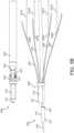
- apparatus 200also includes a plurality of cords or twisted flexible wires 231, 233, 235, 239 and corresponding tubes or rigid linear members 237A-D.
- Tubes 237A-Dare slidably disposed through shaft 206, such that, tubes 237A-D are disposed exterior to tube 272 (i.e., between the exterior of tube 272 and an inner wall of shaft 206).
- the distal ends of each of wires 231, 233, 235, 239are partially disposed through the proximal end of shaft 206 and fixedly coupled to a proximal end 241 of a respective pulling tube 237.
- the distal end of wire 231is coupled to the proximal end 241A of tube 237A
- the distal end of wire 233is coupled to the proximal end 241B of tube 237B
- the distal end of wire 235is coupled to the proximal end 241C of tube 237C
- the distal end of wire 239is coupled to the proximal end 241D of tube 237D.
- the proximal ends 241A-D of tubes 237A-D, respectivelyare crimped, such that the distal ends of each of wires 231, 233, 235, 239 are fixedly coupled to the proximal ends of tubes 237A, B, C, and D, respectively.
- each wire 231, 233, 235, 239 and its respective tube 237is configured from a single material.
- a proximal end of each of wires 231, 233, 235, 239are coupled to actuator 250C or actuator 250D (shown in FIG. 3E and described below).
- actuators 250C and 250D of assembly 203are shown in accordance with the present disclosure.
- Actuator 250Cincludes tubular member 262, where the proximal ends of wires 231 and 239 are wrapped around tubular member 262, as will be described below.
- Actuator 250Dincludes tubular member 264, where the proximal ends of wires 233 and 235 are wrapped around tubular member 264, as will be described in greater detail below.
- tubular member 262is configured to rotate in a direction A1 or in an opposite direction B1 and tubular member 264 is configured to rotate in a direction A2 or an opposite direction B2 in response to each of actuators 250C and 250D being rotated by a motor.
- the proximal end of wire 231is wrapped around tubular member 262 in a first direction (e.g., direction A1) and the proximal end of wire 239 is wrapped around tubular member 262 in a second direction (e.g., direction B1) being opposite to the first direction.
- a portion of tubular member 262includes a pair of threads that are embedded around tubular member 262 in a spiraling manner in opposite directions relative to each other. The pair of threads are each configured to receive the proximal ends of wires 231, 239 to be coupled to and wrapped around tubular member 262 in opposite directions.
- tubular member 262when tubular member 262 is rotated in the first direction A1, wire 231 is rotated about tubular member 262, such that, an additional amount of wire 231 is wrapped around tubular member 262 thus pulling wire 231 and tube 237A within tube 272 in a proximal direction toward assembly 203.
- wire 239is unwrapped from tubular member 262 causing tension to be released from wire 239 and allowing wire 239 and tube 237D to travel in a distal direction within tube 272.
- tubular member 262when tubular member 262 is rotated in the second direction B1, wire 231 is unwrapped from tubular member 262 causing tension to be released from wire 231 and allowing wire 231 and tube 237A to travel in a distal direction within tube 272. As tubular member 262 is rotated in direction B1, an additional amount of wire 239 is wrapped around tubular member 262, thus pulling wire 239 and tube 237D within tube 272 in a proximal direction toward assembly 203.
- the proximal ends of wires 233, 235are wrapped around tubular member 264.
- the proximal end of wire 235is wrapped around tubular member 264 in a first direction (e.g., direction A2) and the proximal end of wire 233 is wrapped around tubular member 264 in a second direction (e.g., direction B2) being opposite to the first direction.
- a portion of tubular member 264has a pair of threads that are embedded around tubular member 264 in a spiraling manner in opposite directions relative to each other. The pair of threads are each configured to receive the proximal ends of wires 233, 235 to be coupled to and wrapped around tubular member 264 in opposite directions.
- tubular member 264when tubular member 264 is rotated in the first direction A2, wire 235 is rotated about tubular member 264, such that, an additional amount of wire 235 is wrapped around tubular member 264 thus pulling wire 235 and tube 237C within tube 272 in a proximal direction toward assembly 203.
- wire 233is unwrapped from tubular member 264 causing tension to be released from wire 233 and allowing wire 233 and tube 237B to travel in a distal direction within tube 272.
- tubular member 264when tubular member 264 is rotated in the second direction B2, wire 235 is unwrapped from tubular member 264 causing tension to be released from wire 235 and allowing wire 235 and tube 237C to travel in a distal direction within tube 272. As tubular member 264 is rotated in direction B2, an additional amount of wire 233 is wrapped around tubular member 264, thus pulling wire 233 and tube 237B within tube 272 in a proximal direction toward assembly 203.
- assembly 203also includes a flexible twisted wire 253, shown in FIG. 3D .
- One end of flexible twisted wire 253is wrapped around actuator 250B and the other end of wire 253 is coupled to interfacing block 256.
- actuator 250Bis rotated (e.g., via a motor, as described above) in a first direction (e.g., direction A3), cable 253 unwraps from actuator 250B and tension is released from wire 253.
- interfacing block 256is biased toward sealing block 260 (e.g., via a spring).
- interfacing block 256when tension is released from wire 253 (i.e., via rotating actuator 250B in a first direction A3), interfacing block 256 is biased in a distal direction toward block 260, causing wire 270 to be advanced in a distal direction (i.e., toward tip 208) within tube 272.
- actuator 250Bis rotated in a second direction (e.g., direction B3), an additional amount of wire 253 is wrapped around actuator 250B, causing wire 253 to pull interfacing block 256 in a proximal direction away from block 260, which also causes wire 270 to be retracted in a proximal direction (i.e., away from tip 208) within tube 272.
- proximal and distal motion of block 256may be controlled solely by actuator 250B and wire 253 without requiring block 256 to be biased toward sealing block 260.
- each end of flexible twisted wire 253may be wrapped around actuator 250B in an opposite direction (i.e., one end is wrapped around actuator 250B in direction A3 and the other end is wrapped around actuator 250B in a direction B3).
- a central portion of wire 253is coupled to interfacing block 256 and a constant tension is maintained in wire 253.
- actuator 250BWhen actuator 250B is rotated in a first direction (e.g., A3), a first end of wire 253 is further wrapped around actuator 250B and a second end of wire 253 is unwrapped from around actuator 250B, causing block 256 to slide in a distal direction and causing wire 270 to extend in a distal direction.
- actuator 250BWhen actuator 250B is rotated in a second direction (e.g., B3), the first end of wire 253 is unwrapped from around actuator 250B and the second end of wire 256 is further wrapped around actuator 250B, causing block 253 to slide in a proximal direction and causing wire 270 to retract in a proximal direction.
- actuator 250Ais coupled to a proximal end of shaft 206, such that, when actuator 250A is rotated, shaft 206 is rotated in an opposite direction.
- shaft 206is rotated in a direction B4.
- actuator 250Ais rotated in an opposite direction B4.
- shaft 206is rotated in the opposite direction A4.
- a distal portion of shaft 206is coupled to tip 208.
- actuator 250Amay be rotated to rotate tip 208.
- tube 272is configured to have sufficient flexibility to be twisted within shaft 206 to enable the rotation of shaft 206.
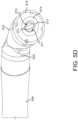
- Robotic tip 208includes electrode 240, ceramic insert 214, tip holder 216, and hinging members 220, 222, and 224. Ceramic insert 214 and tip holder 216 are each configured in a generally cylindrical shape. Ceramic insert 214 includes a distal end 201 and a proximal end 205 and a channel extending from end 201 to end 205 through the interior of insert 214.
- Tip holder 216includes a distal end 207 and a proximal end 209 and a channel extending from end 207 to end 209 through the interior of holder 216. As shown in FIG. 5A , proximal end 205 of ceramic insert 214 is disposed into and fixedly coupled to the distal end 207 of holder 216. It is to be appreciated that the ceramic insert 214 and tip holder 216 together form an electrode housing, with the distal end 201 of ceramic insert 214 being the distal end of the electrode housing and the proximal end 209 of tip holder 216 being the proximal end of the housing. Proximal end 209 of tip holder 216 is disposed over the distal end of tube 272. Although not shown, a rubber gasket is disposed around the distal end of tube 272 within holder 216. The rubber gasket forms a seal around the distal end of tube 272 to prevent leakage of the inert gas at the tip 208.
- a distal end of shaft 206is coupled to hinging member 224, such that, a distal end of tube 272 is disposed through apertures 221, 223, 225 of hinging members 220, 222, 224 ( FIGS. 6A and 6B further illustrate apertures of hinging members 220, 222, 224).
- the distal end of tube 272is coupled to proximal end 209 of tip holder 216.
- a distal end of wire 270is disposed through the distal end of tube 272, the holder 216, and ceramic insert 214. As shown in FIG. 5C , the distal end of wire 270 is coupled to an electrode 240, where electrode 240 is slidably disposed through the inner channel of ceramic insert 214.
- electrode 240is configured as a conducting blade. As shown in FIG. 5C , electrode 240 includes a distal end 244 and a proximal end 242. The distal end of wire 270 is coupled to the proximal end 242 of electrode 240. Electrode 240 also includes extension members 247, 248 and a blade portion 246, which extends distally from extension members 247, 248 to distal end 244 of electrode 240. It is to be appreciated that blade portion 246 is configured with sharp cutting edges that are suitable for mechanical cutting (i.e., excising tissue with no RF energy being applied to the blade portion similar to using a scalpel or the like). Although, electrode 240 is shown and described as a conducting blade, it is to be appreciated that in other embodiments electrode 240 may be configured as a conducting needle or any other type of shape suitable for use as a conducting electrode in surgical applications.
- ceramic insert 214includes a pair of diametrically opposed slots 211 and 213 disposed in the inner wall of the channel of insert 214. Extension members 247, 248 of electrode 240 are slidably disposed within slots 211, 213, respectively, such that electrode 240 is slidable with respect to ceramic insert 214. In this way, when actuator 250B is rotated in a first direction or a second opposite direction to slidably extend or retract interfacing block 256, wire 270 is also extended or retracted within tube 272 causing electrode 240 to be extended or retracted. It is to be appreciated that, since ceramic insert 214 is fixedly coupled to tip holder 216 such that electrode 240 and ceramic insert are fixed rotationally with respect to tip holder 216.
- electrode 240is shown in an advanced or extended position in accordance with the present disclosure. As shown in FIG. 5E , when electrode 240 is extended (by rotating actuator 250B), the distal end 244 of electrode 240 extends passed the distal end 201 of insert 214 until the blade portion 246 is disposed passed distal end 201 of insert 214.
- apparatus 200includes flexible wires 230, 232, 234, and 236.
- the distal ends of each of wires 230, 232, 234, 236are fixedly coupled to the proximal end 209 of holder 216.
- the proximal ends of wires 230, 232, 234, 236are each partially-disposed through the distal end of shaft 206 and fixedly coupled to the distal ends 243 of tubes 237, where the proximal end of wire 230 is coupled to distal end 243A of tube 237A, the proximal end of wire 232 is coupled to distal end 243B of tube 237B, the proximal end of wire 234 is coupled to distal end 243C of tube 237C, and the proximal end of wire 236 is coupled to distal end 243D of tube 237D.
- each of distal ends 243are crimped, such that the proximal ends of wires 230, 232, 234, 236 are fixedly coupled to distal ends 243.
- wires 230, 232, 234, 235, respective tubes 237 and respective wires 231, 233, 235, 239are configured from a single material and are of unitary constructions.
- wire 230, respective tube 237A and wire 231may be a single wire or component as opposed to three separate components as shown.
- tubes 237are configured as rigid tubes and slidably disposed within shaft 206. Tubes 237 are configured to transfer the pushing and pulling (i.e., the creation and release of tension) of wires 231, 233, 235, 239 responsive to the rotation of actuators 250C and 250D to wires 230, 232, 234, and 236.
- apparatus 200includes 4 pulling mechanisms comprising one tube and two wires: (1) wires 230, 231, and tube 237A; (2) wires 232, 233, and tube 237B; (3) wires 234, 235, and tube 237C; and (4) wires 236, 239, and tube 237D.
- tubular member 262 of actuator 250Cwhen tubular member 262 of actuator 250C is rotated in a direction A1 (shown in FIG. 3E ), tension is created in wire 234 and tension is released in wire 232.
- tubular member 262 of actuator 250Cis rotated in a direction B1, tension is released in wire 234 and tension is created in wire 232.
- tubular member 264 of actuator 250Dis rotated in a direction A2 (shown in FIG. 3E )
- tensionis created in wire 230 and tension is released in wire 236.
- tubular member 264 of actuator 250Dis rotated in a direction B2
- tensionis released in wire 230 and tension is created in wire 236.
- Each pulling mechanismis configured to transfer the pushing and pulling of wires 231, 233, 235, 239 (created in response to the rotation of actuators 250C and 250D) to a hinging mechanism of tip 208.
- the hinging mechanismincludes hinging members 220, 222, 224.
- Hinging members 220, 222, 224are included in robotic tip 208 to enable tip 208 to be pivoted and rotated relative to shaft 206 in a variety of ways.
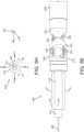
- FIGS. 6A and 6Bexploded views of hinging members 220, 222, 224 are shown in accordance with the present disclosure.
- Hinging members 220, 222, 224are each configured in a generally cylindrical shape.
- Hinging member 220includes apertures, 221, 276A, 277A, 278A, and 279A and a curved surface 280 having protruding or convex portions 281, 282 and recessed concave portions 283, 284, where protruding portions 281, 282 are diametrically opposed about surface 280 and recessed portions 283, 284 are diametrically opposed about surface 280.
- Hinging member 222includes apertures, 223, 276B, 277B, 278B, and 279B and a curved surface 285 having protruding or convex portions 286, 287 and recessed or concave portions 288, 289, where protruding portions 286, 287 are diametrically opposed about surface 285 and recessed portions 288, 289 are diametrically opposed about surface 285.
- Hinging member 222also includes a curved surface 290 having recessed or concave portions 291, 292 and protruding or convex portions 293, 294, where recessed portions 291, 292 are diametrically opposed about surface 290 and protruding portions 293, 294 are diametrically opposed about surface 290.
- Hinging member 224includes apertures, 225, 276C, 277C, 278C, and 279C and a curved surface 295 having recessed or concave portions 296, 297 and protruding or convex portions 298, 299, where recessed portions 296, 297 are diametrically opposed about surface 295 and protruding portions 298, 299 are diametrically opposed about surface 295.
- Hinging member 220is hingedly coupled to hinging member 222, such that, protruding portion 281 of surface 280 is hingedly coupled to protruding portion 286 and protruding portion 282 of surface 280 is hingedly coupled to protruding portion 287.
- hinging member 220may be pivoted about hinging member 222 until recessed portion 283 of surface 280 comes into contact with recessed portion 289 of surface 285.
- hinging member 220may be pivoted about hinging member 222 until recessed portion 284 of surface 280 comes into contact with recessed portion 288 of surface 285.
- Hinging member 222is hingedly coupled to hinging member 224, such that, protruding portion 293 of surface 290 is hingedly coupled to protruding portion 299 of surface 295 and protruding portion 294 of surface 290 is hingedly coupled to protruding portion 298 of surface 295.
- hinging member 222may be pivoted about hinging member 224 until recessed portion 291 of surface 290 comes into contact with recessed portion 296 of surface 295.
- hinging member 222may be pivoted about hinging member 224 until recessed portion 292 of surface 290 comes into contact with recessed portion 297 of surface 295.
- hinging member 224is coupled to a distal end of shaft 206 and hinging member 220 is coupled to proximal end 209 of holder 216.
- the distal end of wire 230is disposed through apertures 276A, 276B, 276C of hinging members 220, 222, 224, respectively, and fixedly coupled to proximal end 209 of holder 216.
- the distal end of wire 232is disposed through apertures 277A, 277B, 277C of hinging members 220, 222, 224, respectively, and fixedly coupled to proximal end 209 of holder 216.
- the distal end of wire 234is disposed through apertures 278A, 278B, 278C of hinging members 220, 222, 224, respectively, and fixedly coupled to proximal end 209 of holder 216.
- the distal end of wire 236is disposed through apertures 279A, 279B, 279C of hinging members 220, 222, 224, respectively, and fixedly coupled to proximal end 209 of holder 216.
- actuators 250C and 250Dmay be rotated (in directions A1/A2 or B1/B2, shown in FIG. 3E ) to pull or create tension in wires 230, 232, 234, 236 or release tension in wires 230, 232, 234, 236.
- the design of hinging members 220, 222, 224is configured to take advantage of this ability to pivot tip holder 216 (and thus electrode 240) in a plurality of ways. As will be described in greater detail below, hinging members 222, 224 enable holder 216 to be pivoted relative to shaft 206 along a first two-dimensional plane responsive to the selective pulling of one or more of wires 230, 232, 234, 236. Referring to FIG.
- the first two-dimensional planeis indicated by the x-y plane, where the y-axis corresponds to the longitudinal axis along which shaft 206 is disposed on and the x-axis traverses the y-axis.
- hinging members 220, 222enable holder 216 to be pivoted relative to shaft 206 along a second two-dimensional plane responsive to the selective pulling of one or more of wires 230, 232, 234, 236.
- the second two-dimensional planeis indicated by the y-z plane in FIG. 5E , where the z-axis traverses the y-axis.
- hinging members 220, 222, 224enable three-dimensional pivoting of holder 216 to shaft 206.
- tubular member 262when tubular member 262 is rotated in direction A1 and tubular member 264 is rotated in a direction B2, tension is created in wires 230 and 232 and tension is released in wires 234 and 236 to pivot hinging member 222 about hinging member 224, such that, recessed portion 291 of surface 290 is drawn toward recessed portion 296 of surface 295 to pivot holder 216 in a direction E along the y-z plane (indicated in FIG. 5E ).
- tubular member 262When tubular member 262 is rotated in a direction B1 and tubular member 264 is rotated in a direction A2, tension is created in wires 234 and 236 and tension is released in wires 230 and 232 to pivot hinging member 222 about hinging member 224, such that, recessed portion 292 of surface 290 is drawn toward recessed portion 297 of surface 295 to pivot holder 216 in a direction F along the y-z plane (indicated in FIG. 5E ), where direction F is opposite to direction E.
- robotic tip 208is shown with tip holder 216 pivoted in a direction F in accordance with the present disclosure.
- tubular member 262 and 264are each rotated in directions A1, A2, respectively, tension is created in wires 230 and 234 and tension is released in wires 232 and 236 to pivot hinging member 220 about hinging member 222, such that, recessed portion 283 of surface 280 is drawn toward recessed portion 289 of surface 285 to pivot holder 216 in a direction C along the y-x plane (i.e., a direction perpendicular to directions E and F).
- tubular members 262 and 264When tubular members 262 and 264 are each rotated in opposite directions B1, B2, respectively, tension is created in wires 232 and 236 and tension is released in wires 230 and 234 to pivot hinging member 220 about hinging member 222, such that, recessed portion 284 of surface 280 is drawn toward recessed portion 289 of surface 285 to pivot holder 216 in a direction D along the y-x plane (i.e., perpendicular to directions E and F), where direction D is opposite to direction C.
- wires 230, 232, 234, 236may be pulled or released by actuators 250C and 250D to pivot holder 216 threedimensionally in directions between directions C, D, E, and F creating a hemi-sphere of possible orientations for holder 216 (and thus electrode 240) relative to shaft 206 using the design of robotic tip 208.
- one of tubular members 262/264may be rotated in a direction A/B, while the other tubular member 262/264 is either maintained stationary (or rotated fewer revolutions) relative to the first tubular member 262/264.
- tubular member 262is rotated in a direction A1
- tubular member 264is maintained in a stationary position (or rotated slightly in direction B2)
- tensionis created in wire 230 and released in wire 236, such that, wire 230 has more tension than wires 232, 234, and 236, and wire 236 has less tension than wires 230, 232, 234
- the resulting tensionspivot holder 216 in a direction between directions E and C.
- robotic tip 208is shown with tip holder 216 pivoted in a direction between directions C and E.
- actuators 250C and 250Dmay be used to control and vary the tension in any one of the wires 230, 232, 234, 236 in many different ways to effectuate many different orientations for holder 216 relative to shaft 206.
- tubular members 262, 264are maintained in a static position, such that, equal tension is maintained in all of wires 230, 232, 234, 236 and no resulting force is applied to tip 208 in direction C, D, E, F.
- tubular members 262, 264are appropriately rotated until an equal amount of tension is reached in each of wires 230, 232, 234, 236.
- actuator 250Amay be rotated (in directions A4 or B4, shown in FIG. 3E ) to rotate shaft 206.
- actuator 250AWhen actuator 250A is rotated in a first direction (e.g., direction A4), shaft 206 and tip 208 are rotated in an opposite direction (e.g., direction B4, shown in FIG. 5H ).
- actuator 250AWhen actuator 250A is rotated in a second direction (e.g., direction B4), shaft 206 and tip 208 are rotated in an opposite direction (e.g., direction A4, shown in FIG. 5H ).
- the ability to rotate tip 208further increases the amount of orientations and positions achievable by tip holder 216 (and thus electrode 240).
- electrode 240is configured in a generally planar shape.
- gas passageways 271, 273are formed on either side of electrode 240 (shown in FIG. 5D ). In this way, when gas is provided from assembly 203, through tube 272, and through the inner channels of tip holder 216 and ceramic insert 214, the gas will pass over electrode 240 and out of the distal end 201 of ceramic tip 201.
- a rubber sealing gasketis disposed over the distal end of tube 272, such that, the sealing gasket prevents gas provided through tube 272 into the inner channels of holder 216 and insert 214 from escaping from the distal end of tube 272 and the proximal end 209 of holder 216 as gas flows.
- apparatus 200When electrode 240 is in the retracted position, i.e., disposed within the inner channel of ceramic insert 214, as shown in FIG. 5A , apparatus 200 is suitable for generating plasma.
- RF energyis conducted to blade portion 246 of electrode 240 from an electrosurgical generator such, as ESU 12, via cable 210, wire 258 and wire 270.
- An inert gassuch as helium or argon, is then supplied through the tube 272 from either the electrosurgical generator or an external gas source coupled to tube 272 via cable 210 and gas port 252.
- a cold plasma beamis generated and emitted from the distal end 201 of ceramic insert 214.
- the plasma beammay then be used in a desired surgical application.
- electrode 240is shown in an extended or advanced position such that blade portion 246 is extended passed the distal end 201 of ceramic insert 214. It is to be appreciated that, as long as electrode 240 is not in contact with the tissue of a patient, while electrode 240 is in an advanced position, apparatus 200 is also suitable for generating plasma in the manner described above (i.e., by providing inert gas flow over electrode 240, while electrode is held at high voltage and high frequency). Furthermore, while electrode 240 is in an advanced position, apparatus 200 can also be used for two cutting modes: mechanical cutting and electrosurgical cutting. In the mechanical cutting mode, RF or electrosurgical energy is not applied to wire 270 or electrode 240, and therefore, the electrode 240 is in a de-energized state.
- mechanical cutting modeRF or electrosurgical energy is not applied to wire 270 or electrode 240, and therefore, the electrode 240 is in a de-energized state.
- the blade portion 246 of electrode 240can be used to excise tissue via mechanical cutting, i.e., the blade portion makes physical contact with the tissue.
- gasmay be applied to electrode 240 (while electrode 240 is advanced or retracted) to generate a cold plasma beam for cauterization, sterilization and/or hemostasis of the operative patient site.
- electrode 240In the electrosurgical cutting mode, electrode 240 is advanced and used while both electrically energized and enveloped with inert gas flow. This configuration resembles an electrosurgical knife approach, where the electrosurgical energy does the cutting. However, with the addition of the inert gas flow, cuts made show virtually no eschar, with very little collateral damage along the side walls of the cut. The cutting speed is considerably faster, with less mechanical cutting resistance as compared to when the knife blade is not electrically energized, i.e., the mechanical cutting mode. Hemostasis is also affected during this process.
- electrosurgical apparatus 200is configured to effectuate the cutting motion of electrode 240 (i.e., the translational path of electrode 240 across tissue to treat or otherwise remove tissue) via the rotation of actuators 250A-D in multiple ways.
- the path of electrode 240 during either of the cutting modesmay be controlled via the selective rotation of actuators 250C and 250D to pivot tip 208 relative to shaft 206 as desired.
- the path of electrode 240may further be controlled via the selective rotation of actuator 250A to rotate shaft 206 and tip 208 about the longitudinal axis.
- the rotation of shaft 206 about the longitudinal axiscauses tip 208 (and thus the extended electrode 240) to move in a circular motion.
- Rotation of shaft 206 and tip 208also serves as a means to choose the orientation of the sharp edges of electrode 240 to enable cutting at varying angles across tissue.
- the path of electrode 240may further be controlled by changing the length electrode 240 extends past distal end 201 of ceramic insert 214 via the selective rotation of actuator 250B. By altering the length electrode 240 extends past distal end 201, the length and depth of cuts or incisions to patient tissue can be selected with high precision as desired.
- the length electrode 240 extends past distal end 201may also be oscillated or varied in time (by alternating the directions A3 and B3 that actuator 250B is rotated in) to create a sawing or puncturing motion of electrode 240.
- the sawing or puncturing motionmay be implemented in the mechanical cutting mode to aid in cutting tissue.
- blocks 256 and 260may be configured as a single component.
- apparatus 200is shown with a block or sliding member 350 instead of blocks 256, 260 in accordance with the present disclosure.
- Block 350includes ends 351, 352, and tube receiving members 356, 358, where tube receiving member 358 extends from a surface 354 of block 350.
- Block 350is slidably mounted to brackets 251A, 251B, where end 351 is slidably mounted to bracket 251A and end 352 is slidably mounted to bracket 251B.
- a central portion of wire 253(shown in FIG. 3D ) is coupled to block 350.
- first and second ends of wire 253are wrapped around actuator 250B in an opposite direction (i.e., one end is wrapped around actuator 250B in direction A3 and the other end is wrapped around actuator 250B in a direction B3).
- actuator 250Bis rotated in a first direction (e.g., A3)
- a first end of wire 253is further wrapped around actuator 250B and a second end of wire 253 is unwrapped from around actuator 250B, causing block 350 to slide in a distal direction, as shown in FIG. 7A .
- actuator 250BWhen actuator 250B is rotated in a second direction (e.g., B3), the first end of wire 253 is unwrapped from around actuator 250B and the second end of wire 256 is further wrapped around actuator 250B, causing block 350 to slide in a proximal direction, as shown in FIG. 7B .
- a second directione.g., B3
- Tube receiving member 358is configured to receive an end of port 252. It is to be appreciated that flexible plastic tube 360 replaces tube 272 in the present embodiment. A distal end of the tube 360 is coupled to tip 208 and a proximal end of tube 360 is coupled to tube receiving member 356. Tube 360 is configured to be stretchable along the longitudinal axis defined by shaft 206 to accommodate the proximal and distal movements of block 350 within brackets 251A, 251B. Internal to block 350, tube receiving members 356, 358 are connected via a channel or passageway. In this way, gas is provided via a gas source through gas port 252 and into tube 360 via the internal channel connecting members 356, 358. Gas is further provided from tube 360 to tip 208.
- wire 270is disposed through tube 360, where a distal end of wire 270 is coupled to electrode 240.
- the proximal end of wire 270is disposed through a hollow interior of tube receiving member 356 and coupled to cable 258, for example, via a conducting screw 370.
- wire 270is advanced in a distal direction to extend electrode 240.
- wire 270is retracted in a proximal direction to retract electrode 240.
- wire 362replaces wire 270.
- wire 362is a flexible stainless steel string with Teflon coating.
- Wire 362is disposed through tube 360, where a distal end of wire 362 is coupled to electrode 240 and a proximal end of wire 362 enters the interior of block 350 and is coupled to cable 258, e.g., via screw 370.
- Wire 362is configured to conduct electrosurgical energy provided from cable 258 (via an ESU) to electrode 240.
- wire 362is only configured for pulling electrode 240 in a proximal direction.
- a spring(not shown) is disposed within tip 208 and biases electrode 240 in a distal direction, such that, electrode 240 is in an extended position (as described above) unless it is pulled on by wire 362.
- actuator 250Bmay be rotated in a first direction to slide block 350 in a proximal direction (as shown in FIGS. 7B , 7C ) to pull wire 362 in a proximal direction, such that, electrode 240 is retracted into tip 208.
- Actuator 250Bmay be rotated in a second direction to slide block 350 in a distal direction (as shown in FIG. 7A ), thereby, releasing the tension in wire 362 and allowing electrode 240 to be biased by the spring in tip 208 toward an extended position.
- tubes 272 and 360are shown and described as tubes including a single interior channel or lumen for providing a single gas to tip 208, in another embodiment of the present disclosure, tubes 272 and/or 360 may be configured as multi-lumen or multi-channel tubes for providing two or more gases to tip 208.
- gas port 252 and cable 210are each configured to provide two or more gases to the multi-lumen tubes 272 and/or 360, where each gas provided corresponds to a different lumen or channel of tubes 272 and/or 360.
- one of the channels or lumens of the multi-lumen tubes 272 and/or tube 360may be coupled to a source providing air-suction. In this way, tip 208 may be configured to also provide aspiration to a surgical site as desired.
- assembly 203may include or be coupled to at least one processor configured to control the speed and direction of rotations of each of the motors coupled to actuators 250A-D, thus, also controlling the speed and direction of rotations of each of actuators 250A-D.
- the processormay include a mapping to the amount (i.e., fraction and/or number of revolutions) that each of actuators must be rotated to create the desired movement, orientation, extension, and retraction of electrode 240. It is to be appreciated that the processor may be included in assembly 203, or alternatively, may be external to assembly 203.
- apparatus 200may be controllable via a separate peripheral device coupled to the processor described above.
- the movement of robotic tip 208may be controllable via a mouse, keyboard, joystick, or other input-receiving device coupled to the processor and apparatus 200.
- the input receiving devicemay be a device that tracks the hand, wrist, and finger movements of the user.
- the movements of the user's hand, wrist, and fingermay be tracked and mapped (e.g., via a processing device as described above) to the appropriate rotations of actuators 250, such that, robotic tip 208 mimics the movements of the user.
- the input-receiving devices described abovemay be coupled to a processing device (e.g., a computer, a processor of ESU 12, and/or a processor of apparatus 200) configured to control actuators 250 of apparatus 200 and/or the motors coupled to actuators 250.
- a processing devicee.g., a computer, a processor of ESU 12, and/or a processor of apparatus 200
- the processor and input receiving devicemay also be in communication with ESU 12 and the gas supply to control the plasma generation of electrode 240.
- the processormay be configured to send a signal to ESU 12 and/or the gas supply in response to one or more inputs received from the input-receiving device to receive electrosurgical energy and/or gas via cable 210 to be provided to tip 208 to generate plasma or be used in electrosurgical cutting.
- the input receiving devicemay include one or more foot pedals or buttons to activate different modes that ESU 12 is capable of (described above).
- a first foot pedalmay be configured to activate J-Plasma mode when pressed, while a second foot pedal may be configured to activate Cool-Coag .
- shaft 206is made of a rigid material, such as, but not limited to, carbon fiber.
- tip 208 of apparatus 200may be inserted through a cannula or trocar for use in various surgical applications, such as, laparoscopic surgery. Since, as described above, tip 208 is configured to be manipulated as desired to achieve a plurality of orientations and positions relative to shaft 206 from a distance via the rotations of actuators 250A-D, tip 208 does not require a separate device or mechanism, e.g., forceps, to interact with tip 208 to control the orientations and positions of tip 208 during surgical applications.
- a separate device or mechanisme.g., forceps
- a cannula or trocar of smaller diameter than normally usedmay be used with electrosurgical apparatus 200 (since only shaft 206 and tip 208 is required to pass through the cannula or trocar) and an incision of a smaller diameter than normal may be created on the patient.
Landscapes
- Health & Medical Sciences (AREA)
- Surgery (AREA)
- Life Sciences & Earth Sciences (AREA)
- Engineering & Computer Science (AREA)
- Biomedical Technology (AREA)
- Public Health (AREA)
- Nuclear Medicine, Radiotherapy & Molecular Imaging (AREA)
- Veterinary Medicine (AREA)
- General Health & Medical Sciences (AREA)
- Heart & Thoracic Surgery (AREA)
- Medical Informatics (AREA)
- Molecular Biology (AREA)
- Animal Behavior & Ethology (AREA)
- Physics & Mathematics (AREA)
- Otolaryngology (AREA)
- Plasma & Fusion (AREA)
- Robotics (AREA)
- Surgical Instruments (AREA)
Description
- This application claims priority to
U.S. Provisional Patent Application No. 62/512,538, filed May 30, 2017 - The present disclosure relates generally to electrosurgery and electrosurgical systems and apparatuses, and more particularly, to an electrosurgical apparatus with a robotic tip and a retractable electrode for use in cold plasma applications, electrosurgical cutting and mechanical cutting.
US 2013/218005 A1 is directed at a minimally invasive neurosurgical intracranial robot system that is introduced to the operative site by a neurosurgeon through a narrow surgical corridor. The robot ofUS 2013/218005 A1 is passed through a cannula and is attached to the cannula by a latching mechanism. The robot ofUS 2013/218005 A1 has several links interconnected via revolute joints which are tendon-driven by tendons routed through channels formed in the walls of the links. The robot body ofUS 2013/218005 A1 is equipped with a tracking system, a tissue liquefacting end-effector, as well as irrigation and suction tubes.US2015238254A1 is directed at devices and systems for using an end effector.US2009306658 A1 is directed at a manually articulated surgical device that includes an elongate shaft having a distal end coupled to a proximal end of an articulation joint, and an actuation wire extending through the elongate shaft and the articulation joint.- High frequency electrical energy has been widely used in surgery and is commonly referred to as electrosurgical energy. Tissue is cut and bodily fluids are coagulated using electrosurgical energy.
- Electrosurgical instruments generally comprise "monopolar" devices or "bipolar" devices. Monopolar devices comprise an active electrode on the electrosurgical instrument with a return electrode attached to the patient. In monopolar electrosurgery, the electrosurgical energy flows through the active electrode on the instrument through the patient's body to the return electrode. Such monopolar devices are effective in surgical procedures where cutting and coagulation of tissue are required and where stray electrical currents do not pose a substantial risk to the patient.
- Bipolar devices comprise an active electrode and a return electrode on the surgical instrument. In a bipolar electrosurgical device, electrosurgical energy flows through the active electrode to the tissue of a patient through a short distance through the tissue to the return electrode. The electrosurgical effects are substantially localized to a small area of tissue that is disposed between the two electrodes on the surgical instrument. Bipolar electrosurgical devices have been found to be useful with surgical procedures where stray electrical currents may pose a hazard to the patient or where other procedural concerns require close proximity of the active and return electrodes. Surgical operations involving bipolar electrosurgery often require methods and procedures that differ substantially from the methods and procedures involving monopolar electrosurgery.
- Gas plasma is an ionized gas capable of conducting electrical energy. Plasmas are used in surgical devices to conduct electrosurgical energy to a patient. The plasma conducts the energy by providing a pathway of relatively low electrical resistance. The electrosurgical energy will follow through the plasma to cut, coagulate, desiccate, or fulgurate blood or tissue of the patient. There is no physical contact required between an electrode and the tissue treated.
- Electrosurgical systems that do not incorporate a source of regulated gas can ionize the ambient air between the active electrode and the patient. The plasma that is thereby created will conduct the electrosurgical energy to the patient, although the plasma arc will typically appear more spatially dispersed compared with systems that have a regulated flow of ionizable gas.
- Atmospheric pressure discharge cold plasma applicators have found use in a variety of applications including surface sterilization, hemostasis, and ablation of tumors. Often, a simple surgical knife is used to excise the tissue in question, followed by the use of a cold plasma applicator for cauterization, sterilization, and hemostasis. Cold plasma beam applicators have been developed for both open and endoscopic procedures. In the latter case, it is often desirable to be able to redirect the position of the cold plasma beam tip to a specific operative site. The external incision and pathway for the endoscopic tool may be chosen to avoid major blood vessels and non-target organs, and may not coincide with an optimum alignment for the target internal tissue site. A means of redirecting the cold plasma beam is essential in these situations.
- Elaborate mechanisms have been developed to change the direction of the plasma beam by the surgeon as needed. However, these mechanisms are mechanically complicated, expensive to produce and, in some cases, unwieldy to operate effectively. The small diameter of the endoscopic trocar through which this surgical tool must be inserted places even more severe restrictions on these issues.
- The present disclosure relates to an electrosurgical apparatus with a retractable electrode, e.g., a blade, needle, sharp electrode, etc., for use in cold plasma applications, electrosurgical cutting and mechanical cutting. The present invention is defined by the features described in the independent claims. Additional embodiments are defined in the dependent claims.
- The above and other aspects, features, and advantages of the present disclosure will become more apparent in light of the following detailed description when taken in conjunction with the accompanying drawings in which:
FIG. 1 is an illustration of an exemplary monopolar electrosurgical system in accordance with an embodiment of the present disclosure;FIG. 2 is a perspective view of an electrosurgical device with a robotic tip in accordance with an embodiment of the present disclosure;FIG. 3A is a perspective view of an assembly of the electrosurgical device ofFIG. 2 in accordance with an embodiment of the present disclosure;FIGS 3B-E are perspective views of the assembly ofFIG. 3A with a housing of the assembly removed in accordance with an embodiment of the present disclosure;FIG. 4 is a side view of several components of the electrosurgical apparatus ofFIG. 2 in accordance with an embodiment of the present disclosure;FIG. 5A is a side view of the robotic tip of the electrosurgical apparatus ofFIG. 2 in accordance with an embodiment of the present disclosure;FIGS. 5B and5C are partial exploded views of the robotic tip of the electrosurgical apparatus ofFIG. 2 in accordance with an embodiment of the present disclosure;FIG. 5D is a perspective view of the robotic tip of the electrosurgical apparatus ofFIG. 2 in accordance with an embodiment of the present disclosure;FIG. 5E is a side view of the robotic tip of the electrosurgical apparatus ofFIG. 2 with an electrode in an extended position in accordance with an embodiment of the present disclosure;FIGS. 5F and5G are views of the robotic tip of the electrosurgical apparatus ofFIG. 2 while pivoted in accordance with an embodiment of the present disclosure;FIG. 5H is a view through the distal end of the robotic tip of the electrosurgical apparatus ofFIG. 2 in accordance with an embodiment of the present disclosure;FIGS. 6A and 6B are views of hinging members of the robotic tip of the electrosurgical apparatus ofFIG. 2 in accordance with an embodiment of the present disclosure; andFIGS. 7A-7C are perspective views of the assembly ofFIG. 3A including an alternative sliding block in accordance with an embodiment of the present disclosure.- It should be understood that the drawings are for purposes of illustrating the concepts of the disclosure and are not necessarily the only possible configuration for illustrating the disclosure.
- Preferred embodiments of the present disclosure will be described hereinbelow with reference to the accompanying drawings. In the following description, well-known functions or constructions are not described in detail to avoid obscuring the present disclosure in unnecessary detail. In the drawings and in the description which follow, the term "proximal", as is traditional, will refer to the end of the device, e.g., instrument, apparatus, applicator, handpiece, forceps, etc., which is closer to the user, while the term "distal" will refer to the end which is further from the user. Herein, the phrase "coupled" is defined to mean directly connected to or indirectly connected with through one or more intermediate components. Such intermediate components may include both hardware and software based components.
FIG. 1 shows an exemplary monopolar electrosurgical system generally indicated as 10 comprising an electrosurgical generator (ESU) generally indicated as 12 to generate power for theelectrosurgical apparatus 10 and a plasma generator generally indicated as 14 to generate and apply aplasma stream 16 to a surgical site ortarget area 18 on a patient 20 resting on a conductive plate orsupport surface 22. Theelectrosurgical generator 12 includes at least one transformer generally indicated as 24 that may include a primary and secondary coupled to an electrical source (not shown) to provide high frequency electrical energy to theplasma generator 14. In one embodiment, theelectrosurgical generator 12 comprises an isolated floating potential not referenced to any potential. Thus, current flows between the active and return electrodes. If the output is not isolated, but referenced to "earth", current can flow to areas with ground potential. If the contact surface of these areas and the patient is relatively small, an undesirable burning can occur.- The
plasma generator 14 comprises a handpiece orholder 26 having anelectrode 28 at least partially disposed within afluid flow housing 29 and coupled to thetransformer 24 to receive the high frequency electrical energy therefrom to at least partially ionize noble gas fed to thefluid flow housing 29 of the handpiece orholder 26 to generate or create theplasma stream 16. Theelectrode 28 is configured to be retractable, such that theelectrode 28 may be advanced to extend outside ofhousing 29 or be retracted withinhousing 29. The high frequency electrical energy is fed from the secondary of thetransformer 24 through anactive conductor 30 to the electrode 28 (collectively active electrode) in thehandpiece 26 to create theplasma stream 16 for application to thesurgical site 18 on thepatient 20. Furthermore, a current limitingcapacitor 25 may be provided in series with theelectrode 28 to limit the amount of current being delivered to thepatient 20. - The return path to the
electrosurgical generator 12 is through the tissue and body fluid of thepatient 20, the conductor plate orsupport member 22 and a return conductor 32 (collectively return electrode) to the secondary of thetransformer 24 to complete the isolated, floating potential circuit. - In another embodiment, the
ESU 12 comprises an isolated non-floating potential not referenced to any potential. The plasma current flow back to theESU 12 is through the tissue and body fluid and thepatient 20. From there, the return current circuit is completed through the combined external capacitance to theplasma generator handpiece 26, surgeon and through displacement current. The capacitance is determined, among other things, by the physical size of thepatient 20. Such an electrosurgical apparatus and generator are described in commonly ownedU.S. Patent No. 7,316,682 to Konesky. - It is to be appreciated that in some embodiments ESU 12 may be configured for use with a
handpiece 26 that does not include a dedicated transformer. In this embodiment,ESU 12 includes at least one second transformer configured to perform at least some of the tasks that a transformer withinhandpiece 26 would perform. In this embodiment, theESU 12 is configured for use with ahandpiece 26 that does not include a dedicated transformer, such thatESU 12, is configured to support a new plasma mode, herein called internal J-Plasma mode, or simply J-Plasma mode. J-Plasma mode is designed to allow ahandpiece 26 to generate plasma without requiringhandpiece 26 to include an internal transformer. - It is to be appreciated that in the embodiment described above, where the
handpiece 26 does not include a dedicated transformer, current limitingcapacitor 25 may be removed fromhandpiece 26. In this embodiment,ESU 12 may be configured for use withhandpiece 26 as a closed-loop system, whereESU 12 can effectively limit the current delivered to electrode 28 without the need forhandpiece 26 to include an internal dedicated transformer. - The
ESU 12 of the present disclosure may be configured to generate various different plasma beam effects by modifying the applied high voltage and high frequency waveform of the power provided toelectrode 28 byESU 12. In addition to the generation of cold plasma, these effects include several forms of monopolar coagulation and gas assisted coagulation, also known as Cool Coageffects. It is to be appreciated that in these gas assisted coagulation modes a coagulation waveform is applied to the electrode while an inert gas is present, e.g., Helium, thereby forming a plasma. In this manner, a single electrosurgical apparatus in accordance with the present disclosure may generate 1.) cold plasma discharges, 2.) monopolar coagulation effects and 3.) various gas assisted coagulation discharges, or plasma.
- It is to be appreciated that in various embodiments two high voltage step up output transformers are included in
ESU 12 and are utilized to generate the necessary waveforms. An exemplary system including two high voltage step up output transformers are shown and described in commonly ownedU.S. Patent No. 9,144,453 to Rencher, et al. - One transformer is optimized for high voltage and low current and is utilized in generating the cold plasma beam with the electrode retracted (such as with
electrode 28 and/orelectrode 240, described below). The other transformer is optimized for somewhat lower voltage but higher current required by electrosurgical procedures such as monopolar, bipolar, and coagulation. Buttons on a hand held applicator, such asapplicator 14, or selection of an appropriate foot switch or pedal coupled toESU 12, may be configured to control which transformer inESU 12 is activated for the required procedure to activate the various modes ESU 12 provides for. - In the monopolar coagulation mode, (e.g., activated by pressing an appropriate foot switch, as described above), a coagulation waveform is applied to the electrode and coagulation effects may be applied to target tissue by making contact between the electrode of the electrosurgical device and the target tissue.
- In the plasma coagulation mode, (e.g., activated by a button or an appropriate foot switch of the electrosurgical apparatus, as described above) several forms of gas assisted coagulation (or plasma coagulation) can be affected by spacing the electrode a predetermined distance away from the target tissue, including a pinpoint coagulation mode, a gentle coagulation mode, and a spray coagulation mode. A high crest factor, or ratio of peak voltage to RMS voltage, assures ignition of the flowing inert gas in the various gas assisted coagulation modes. In one embodiment, the coagulation mode to be employed during plasma coagulation (e.g., when an appropriate foot switch or pedal is pressed) is selected at an electrosurgical generator that is providing electrosurgical energy to the apparatus. In this way, after a coagulation mode is selected at the generator (e.g., pinpoint, gentle, or spray coagulation mode), when a coagulation button or foot switch of the electrosurgical apparatus (e.g.,
applicator 14 orapparatus 200 described below) is activated, the selected coagulation mode is employed in the plasma beam emitted by the electrosurgical apparatus. - In the pinpoint and gentle gas assisted coagulation modes, a relatively short period exists between the plasma generating pulse groups. Residual ions from the previous discharge path ensure that subsequent discharges follow the same path, providing a plasma beam with the same pointing accuracy as the cold plasma beam, but with substantially higher current and enhanced coagulation capability.
- The gas assisted spray mode, by contrast, has a much longer period between pulses (e.g., by applying the fulguration mode waveform to the electrode), permitting any residual ions to recombine. There is, therefore, no preferential residual discharge path and the individual discharges randomly cover a much larger area.
- As in the cold plasma beam mode, a wide range of physiological effects can be affected in the various gas assisted coagulation modes by adjusting the ratio of electrical power in the beam and the inert gas flow rate.
- From the above, it is to be appreciated that a single electrosurgical apparatus (e.g.,
applicator 14 and/orapparatus 200, described below) in accordance with the present disclosure may include at least three activation modes including a cold plasma mode, a monopolar coagulation mode (where an electrode of the electrosurgical apparatus is touching target tissue) and a gas assisted or plasma coagulation mode (where an electrode of the electrosurgical apparatus is spaced apart from the target tissue without touching the tissue). - The present disclosure provides an electrosurgical apparatus including an articulating distal end configured to be pivoted and preferably rotated in a plurality of directions. The electrosurgical apparatus of the present disclosure is configured to be used in robotic surgical systems to perform a wide variety of surgeries, as will be described below. Referring to
FIG. 2 , anelectrosurgical apparatus 200 with a roboticdistal tip 208 is shown in accordance with the present disclosure.Apparatus 200 includes adistal end 215 and aproximal end 217, where anassembly 203 is disposed atproximal end 217 ofapparatus 200.Assembly 203 includes ahousing 202 and abase 204, wherehousing 202 is coupled tobase 204. As will be described in greater detail below, one or more components ofapparatus 200 are coupled tobase 204 and disposed withinhousing 202. Ashaft 206 and acable 210 are each coupled toassembly 203.Cable 210 is further coupled toconnector 212 andshaft 206 is further coupled to roboticdistal tip 208. It is to be appreciated thatFIG. 2 illustrates theapparatus 220 with thehousing 202 in a lower portion of the figure, while the upper portion ofFIG. 2 illustrates thesame apparatus 200 with the housing removed. - In one embodiment,
connector 212 is configured to be coupled to an ESU, such asESU 12, and a gas supply. It is to be appreciated that in some embodiments, the ESU includes the gas supply. The ESU and gas supply coupled toconnector 212 provide electrosurgical energy and gas viacable 210 toassembly 203. In one embodiment,cable 210 may include one or more flexible gas tubes configured to carry gas from a gas source or supply toassembly 203 and one or more electrically conducting wires configured to provide electrical power and carry electrical signals from the ESU (or any other device coupled toassembly 203 via cable 210) toassembly 203. Gas and electrosurgical energy is provided fromassembly 203 to roboticdistal tip 208 viashaft 206.Tip 208 includes a retractable electrode or blade, which, in combination with the electrosurgical energy and gas provided viaassembly 203 may be used to produce a plasma beam for surgical applications.Assembly 203 includes one or more actuators configured to rotate and pivot roboticdistal tip 208 in a plurality of ways. At least one of the actuators is also be used to extend or retract the electrode inrobotic tip 208. It is to be appreciated that each of the features ofapparatus 200 are described in greater detail below. - Referring to
FIGS. 3A to 3E , various views ofassembly 203 are shown in accordance with the present disclosure. As shown inFIGS. 3A and3B ,shaft 206 is coupled to and extends frombase 204 along a longitudinal axis. In one embodiment,shaft 206 is a rigid carbon fiber tube including a hollow interior. Also, a plurality of actuators 250 are coupled tobase 204. In one embodiment, each of actuators 250 are configured as interfaces that can each be coupled to a motor of an apparatus controllable by a user. In one embodiment, each actuator 250 may include one ormore slots 259 configured to receive a tab or extension member of a mating disk of a motor to couple each actuator 250 to a respective motor. In this way, when the mating disk (or any other mating mechanism for coupling a motor to one of actuators 250) of a motor coupled to an actuator 250 is rotated, the actuator 250 is also rotated. - The rotations of actuators control and manipulate the orientation of
robotic tip 208. For example, as will be described in greater detail below,actuator 250A is configured to control the rotation ofshaft 206 to cause the rotation ofrobotic tip 208,actuator 250B is configured to control the extension and retraction of an electrode or blade of robotic tip 208 (e.g.,electrode 240 described below), andactuators robotic tip 208 about one or more hinging members. - Referring to
FIGS. 3B ,3C , and3D ,cable 210 is coupled toassembly 203 via acable holder 254.Cable holder 254 is configured to provide strain relief forcable 210.Cable holder 254 is coupled to gas port 252 (e.g., a flexible tube suitable for carrying gas), wheregas port 252 is further coupled totube sealing block 260.Cable holder 254 is also coupled tocable 258, wherecable 258 is coupled to interfacing block or slidingmember 256. It is to be appreciated that a gas tube disposed withincable 210 and configured to carry gas from a gas source toassembly 203 is coupled togas port 252. In one embodiment,gas port 252 is a single gas tube disposed throughcable 210 and coupled to the gas source. It is also to be appreciated that one or more electrical wires disposed incable 210 and configured to carry electrical power from an ESU toassembly 203 are coupled tocable 258. In one embodiment,cable 258 is disposed throughcable 210 and coupled to the ESU. - In one embodiment,
tube sealing block 260 is fixedly mounted toassembly 203 viabrackets FIG. 3D ) and interfacingblock 256 is slidably mounted toassembly 203 viabrackets block 256 may be advanced in a distal direction towardtube sealing block 260 or retracted in a proximal direction away fromtube sealing block 260. It is to be appreciated that interfacingblock 256 is coupled to a conductive wire or rod 270 (shown inFIGS. 3D and4 ) disposed throughshaft 206 and coupled to an electrode oftip 208, such that, as interfacingblock 256 is advanced in a distal direction towardtube sealing block 260 or retracted in a proximal direction away fromtube sealing block 260,wire 270 causes the electrode oftip 208 to also be advanced or retracted in the same direction as the movement of interfacingblock 256. In one embodiment,wire 270 is a flexible stainless steel conducting wire of 0.30mm thickness configured to reduce leakage capacitance while still being sufficiently rigid to advance or retract the electrode withintip 208. - For example, referring to
FIG. 4 , blocks 260 and 256 are shown in greater detail in accordance with the present disclosure. As shown inFIG. 4 ,tube sealing block 260 includes atube receiving member 265 and ablock portion 263, wheretube receiving member 265 extends fromblock portion 263 in a direction towardbase 204.Tube receiving member 265 is configured in a generally cylindrical shape with a hollow interior or inner channel.Block portion 263 includes achannel 261, wherechannel 261 extends from anend 267 ofblock portion 263 intotube receiving member 265 such thatchannel 261 and the inner channel oftube receiving member 265 merge.Gas port 252 is coupled to channel 261 viaend 267 ofblock portion 263.Tube receiving member 265 is configured to receive a proximal end of aflexible tube 272, e.g., a flexible Teflon tube. A distal end oftube 272 is coupled to tip 208 (described below). Gas is provided from a gas supply coupled toapparatus 200 viacable 210, throughgas port 252, throughchannel 261 ofgas sealing block 260, through an inner channel oftube 272 to tip 208. As will be described below, the gas may be an inert gas, such as helium, that is used in combination with anelectrode 240 oftip 208 to generate plasma. - Also shown in
FIG. 4 , interfacingblock 256 includesends end 255 is slidably disposed in a slot ofbracket 251A and end 257 is slidably disposed in a slot ofbracket 251B. It is to be appreciated thatbrackets FIG. 3D . A distal end of wire 270 (e.g., a conducting wire) is fixedly coupled to interfacing block 256 (e.g., via a screw or other fastening means).Wire 270 is slidably disposed through an aperture (not shown) ofblock portion 263 of gastube sealing block 260, through tube the inner channel of receivingmember 265, and into the interior ofgas tube 272. As described below, a distal end ofwire 270 is fixedly coupled toelectrode 240, such that, as interfacingblock 256 is advanced towardtube sealing block 260 or away fromtube sealing block 260,wire 270 also slides withintube sealing block 260 andtube 272 in a direction toward or away fromtube sealing block 260 to causeelectrode 240 oftip 208 to be advanced or retracted. In one embodiment,cable 258 ofassembly 203couples cable 210 towire 270, such that, electrosurgical energy can be provided byESU 12 to wire 270 (via cable 258) to energizeelectrode 240 oftip 208. - Although in the embodiments described above,
tube sealing block 260 and interfacingblock 256 are configured as separate components, as will be described below, in other embodiments of the present disclosure, interfacingblock 256 andtube sealing block 260 may be configured as a single component. - Referring again to
FIG. 4 ,apparatus 200 also includes a plurality of cords or twistedflexible wires linear members 237A-D. Tubes 237A-D are slidably disposed throughshaft 206, such that,tubes 237A-D are disposed exterior to tube 272 (i.e., between the exterior oftube 272 and an inner wall of shaft 206). In one embodiment, the distal ends of each ofwires shaft 206 and fixedly coupled to a proximal end 241 of a respective pulling tube 237. For example, the distal end ofwire 231 is coupled to theproximal end 241A oftube 237A, the distal end ofwire 233 is coupled to theproximal end 241B oftube 237B, the distal end ofwire 235 is coupled to theproximal end 241C oftube 237C, and the distal end ofwire 239 is coupled to theproximal end 241D oftube 237D. In one embodiment, the proximal ends 241A-D oftubes 237A-D, respectively, are crimped, such that the distal ends of each ofwires tubes 237A, B, C, and D, respectively. In another embodiment, eachwire wires actuator 250C oractuator 250D (shown inFIG. 3E and described below). For example, referring toFIG. 3E ,actuators assembly 203 are shown in accordance with the present disclosure.Actuator 250C includestubular member 262, where the proximal ends ofwires tubular member 262, as will be described below.Actuator 250D includestubular member 264, where the proximal ends ofwires tubular member 264, as will be described in greater detail below. As indicated inFIG. 3E ,tubular member 262 is configured to rotate in a direction A1 or in an opposite direction B1 andtubular member 264 is configured to rotate in a direction A2 or an opposite direction B2 in response to each ofactuators - The proximal end of
wire 231 is wrapped aroundtubular member 262 in a first direction (e.g., direction A1) and the proximal end ofwire 239 is wrapped aroundtubular member 262 in a second direction (e.g., direction B1) being opposite to the first direction. In one embodiment, a portion oftubular member 262 includes a pair of threads that are embedded aroundtubular member 262 in a spiraling manner in opposite directions relative to each other. The pair of threads are each configured to receive the proximal ends ofwires tubular member 262 in opposite directions. - In this way, when
tubular member 262 is rotated in the first direction A1,wire 231 is rotated abouttubular member 262, such that, an additional amount ofwire 231 is wrapped aroundtubular member 262 thus pullingwire 231 andtube 237A withintube 272 in a proximal direction towardassembly 203. Astubular member 262 is rotated in direction A1,wire 239 is unwrapped fromtubular member 262 causing tension to be released fromwire 239 and allowingwire 239 andtube 237D to travel in a distal direction withintube 272. Additionally, whentubular member 262 is rotated in the second direction B1,wire 231 is unwrapped fromtubular member 262 causing tension to be released fromwire 231 and allowingwire 231 andtube 237A to travel in a distal direction withintube 272. Astubular member 262 is rotated in direction B1, an additional amount ofwire 239 is wrapped aroundtubular member 262, thus pullingwire 239 andtube 237D withintube 272 in a proximal direction towardassembly 203. - The proximal ends of
wires tubular member 264. The proximal end ofwire 235 is wrapped aroundtubular member 264 in a first direction (e.g., direction A2) and the proximal end ofwire 233 is wrapped aroundtubular member 264 in a second direction (e.g., direction B2) being opposite to the first direction. In one embodiment, a portion oftubular member 264 has a pair of threads that are embedded aroundtubular member 264 in a spiraling manner in opposite directions relative to each other. The pair of threads are each configured to receive the proximal ends ofwires tubular member 264 in opposite directions. - In this way, when
tubular member 264 is rotated in the first direction A2,wire 235 is rotated abouttubular member 264, such that, an additional amount ofwire 235 is wrapped aroundtubular member 264 thus pullingwire 235 andtube 237C withintube 272 in a proximal direction towardassembly 203. Astubular member 264 is rotated in direction A2,wire 233 is unwrapped fromtubular member 264 causing tension to be released fromwire 233 and allowingwire 233 andtube 237B to travel in a distal direction withintube 272. Additionally, whentubular member 264 is rotated in the second direction B2,wire 235 is unwrapped fromtubular member 264 causing tension to be released fromwire 235 and allowingwire 235 andtube 237C to travel in a distal direction withintube 272. Astubular member 264 is rotated in direction B2, an additional amount ofwire 233 is wrapped aroundtubular member 264, thus pullingwire 233 andtube 237B withintube 272 in a proximal direction towardassembly 203. - In one embodiment,
assembly 203 also includes a flexibletwisted wire 253, shown inFIG. 3D . One end of flexibletwisted wire 253 is wrapped aroundactuator 250B and the other end ofwire 253 is coupled to interfacingblock 256. When actuator 250B is rotated (e.g., via a motor, as described above) in a first direction (e.g., direction A3),cable 253 unwraps fromactuator 250B and tension is released fromwire 253. In one embodiment, interfacingblock 256 is biased toward sealing block 260 (e.g., via a spring). In this way, when tension is released from wire 253 (i.e., via rotatingactuator 250B in a first direction A3), interfacingblock 256 is biased in a distal direction towardblock 260, causingwire 270 to be advanced in a distal direction (i.e., toward tip 208) withintube 272. When actuator 250B is rotated in a second direction (e.g., direction B3), an additional amount ofwire 253 is wrapped aroundactuator 250B, causingwire 253 to pull interfacingblock 256 in a proximal direction away fromblock 260, which also causeswire 270 to be retracted in a proximal direction (i.e., away from tip 208) withintube 272. - Alternatively, in another embodiment, the proximal and distal motion of
block 256 may be controlled solely byactuator 250B andwire 253 without requiringblock 256 to be biased toward sealingblock 260. In this embodiment, each end of flexibletwisted wire 253 may be wrapped aroundactuator 250B in an opposite direction (i.e., one end is wrapped aroundactuator 250B in direction A3 and the other end is wrapped aroundactuator 250B in a direction B3). A central portion ofwire 253 is coupled to interfacing block 256 and a constant tension is maintained inwire 253. When actuator 250B is rotated in a first direction (e.g., A3), a first end ofwire 253 is further wrapped aroundactuator 250B and a second end ofwire 253 is unwrapped from aroundactuator 250B, causing block 256 to slide in a distal direction and causingwire 270 to extend in a distal direction. When actuator 250B is rotated in a second direction (e.g., B3), the first end ofwire 253 is unwrapped from around actuator 250B and the second end ofwire 256 is further wrapped aroundactuator 250B, causing block 253 to slide in a proximal direction and causingwire 270 to retract in a proximal direction. - In one embodiment,
actuator 250A is coupled to a proximal end ofshaft 206, such that, when actuator 250A is rotated,shaft 206 is rotated in an opposite direction. In this embodiment, when actuator 250A is rotated in a direction A4,shaft 206 is rotated in a direction B4. Alternatively, when actuator 250A is rotated in an opposite direction B4,shaft 206 is rotated in the opposite direction A4. As described below, a distal portion ofshaft 206 is coupled totip 208. In this way,actuator 250A may be rotated to rotatetip 208. It is to be appreciated that, in one embodiment,tube 272 is configured to have sufficient flexibility to be twisted withinshaft 206 to enable the rotation ofshaft 206. - Referring to
FIGS. 5A ,5B , and5C , a side view ofrobotic tip 208 is shown inFIG. 5A and side exploded views oftip 208 are shown inFIGS. 5B and5C in accordance with the present disclosure.Robotic tip 208 includeselectrode 240,ceramic insert 214,tip holder 216, and hingingmembers Ceramic insert 214 andtip holder 216 are each configured in a generally cylindrical shape.Ceramic insert 214 includes adistal end 201 and aproximal end 205 and a channel extending fromend 201 to end 205 through the interior ofinsert 214.Tip holder 216 includes adistal end 207 and aproximal end 209 and a channel extending fromend 207 to end 209 through the interior ofholder 216. As shown inFIG. 5A ,proximal end 205 ofceramic insert 214 is disposed into and fixedly coupled to thedistal end 207 ofholder 216. It is to be appreciated that theceramic insert 214 andtip holder 216 together form an electrode housing, with thedistal end 201 ofceramic insert 214 being the distal end of the electrode housing and theproximal end 209 oftip holder 216 being the proximal end of the housing.Proximal end 209 oftip holder 216 is disposed over the distal end oftube 272. Although not shown, a rubber gasket is disposed around the distal end oftube 272 withinholder 216. The rubber gasket forms a seal around the distal end oftube 272 to prevent leakage of the inert gas at thetip 208. - A distal end of
shaft 206 is coupled to hingingmember 224, such that, a distal end oftube 272 is disposed throughapertures members FIGS. 6A and 6B further illustrate apertures of hingingmembers tube 272 is coupled toproximal end 209 oftip holder 216. A distal end ofwire 270 is disposed through the distal end oftube 272, theholder 216, andceramic insert 214. As shown inFIG. 5C , the distal end ofwire 270 is coupled to anelectrode 240, whereelectrode 240 is slidably disposed through the inner channel ofceramic insert 214. - In one embodiment,
electrode 240 is configured as a conducting blade. As shown inFIG. 5C ,electrode 240 includes adistal end 244 and aproximal end 242. The distal end ofwire 270 is coupled to theproximal end 242 ofelectrode 240.Electrode 240 also includesextension members blade portion 246, which extends distally fromextension members distal end 244 ofelectrode 240. It is to be appreciated thatblade portion 246 is configured with sharp cutting edges that are suitable for mechanical cutting (i.e., excising tissue with no RF energy being applied to the blade portion similar to using a scalpel or the like). Although,electrode 240 is shown and described as a conducting blade, it is to be appreciated that in other embodiments electrode 240 may be configured as a conducting needle or any other type of shape suitable for use as a conducting electrode in surgical applications. - Referring to
FIG. 5D , in one embodiment,ceramic insert 214 includes a pair of diametricallyopposed slots insert 214.Extension members electrode 240 are slidably disposed withinslots electrode 240 is slidable with respect toceramic insert 214. In this way, whenactuator 250B is rotated in a first direction or a second opposite direction to slidably extend or retract interfacingblock 256,wire 270 is also extended or retracted withintube 272 causingelectrode 240 to be extended or retracted. It is to be appreciated that, sinceceramic insert 214 is fixedly coupled totip holder 216 such thatelectrode 240 and ceramic insert are fixed rotationally with respect to tipholder 216. - Referring to
FIG. 5E ,electrode 240 is shown in an advanced or extended position in accordance with the present disclosure. As shown inFIG. 5E , whenelectrode 240 is extended (by rotatingactuator 250B), thedistal end 244 ofelectrode 240 extends passed thedistal end 201 ofinsert 214 until theblade portion 246 is disposed passeddistal end 201 ofinsert 214. - As shown in
FIG. 5B ,apparatus 200 includesflexible wires wires proximal end 209 ofholder 216. The proximal ends ofwires shaft 206 and fixedly coupled to the distal ends 243 of tubes 237, where the proximal end ofwire 230 is coupled todistal end 243A oftube 237A, the proximal end ofwire 232 is coupled todistal end 243B oftube 237B, the proximal end ofwire 234 is coupled todistal end 243C oftube 237C, and the proximal end ofwire 236 is coupled todistal end 243D oftube 237D. In one embodiment, each of distal ends 243 are crimped, such that the proximal ends ofwires wires respective wires wire 230,respective tube 237A andwire 231 may be a single wire or component as opposed to three separate components as shown. - As stated above, tubes 237 are configured as rigid tubes and slidably disposed within
shaft 206. Tubes 237 are configured to transfer the pushing and pulling (i.e., the creation and release of tension) ofwires actuators wires apparatus 200 includes 4 pulling mechanisms comprising one tube and two wires: (1)wires tube 237A; (2)wires tube 237B; (3)wires tube 237C; and (4)wires tube 237D. For example, whentubular member 262 ofactuator 250C is rotated in a direction A1 (shown inFIG. 3E ), tension is created inwire 234 and tension is released inwire 232. Alternatively, whentubular member 262 ofactuator 250C is rotated in a direction B1, tension is released inwire 234 and tension is created inwire 232. Whentubular member 264 ofactuator 250D is rotated in a direction A2 (shown inFIG. 3E ), tension is created inwire 230 and tension is released inwire 236. Alternatively, whentubular member 264 ofactuator 250D is rotated in a direction B2, tension is released inwire 230 and tension is created inwire 236. - Each pulling mechanism is configured to transfer the pushing and pulling of
wires actuators tip 208. Referring again toFIG. 5A , the hinging mechanism includes hingingmembers members robotic tip 208 to enabletip 208 to be pivoted and rotated relative toshaft 206 in a variety of ways. Referring toFIGS. 6A and 6B , exploded views of hingingmembers members member 220 includes apertures, 221, 276A, 277A, 278A, and 279A and acurved surface 280 having protruding orconvex portions concave portions portions surface 280 and recessedportions surface 280. Hingingmember 222 includes apertures, 223, 276B, 277B, 278B, and 279B and acurved surface 285 having protruding orconvex portions concave portions portions surface 285 and recessedportions surface 285. Hingingmember 222 also includes acurved surface 290 having recessed orconcave portions convex portions portions surface 290 and protrudingportions surface 290. Hingingmember 224 includes apertures, 225, 276C, 277C, 278C, and 279C and acurved surface 295 having recessed orconcave portions convex portions portions surface 295 and protrudingportions surface 295. - Hinging
member 220 is hingedly coupled to hingingmember 222, such that, protrudingportion 281 ofsurface 280 is hingedly coupled to protrudingportion 286 and protrudingportion 282 ofsurface 280 is hingedly coupled to protrudingportion 287. In this way, hingingmember 220 may be pivoted about hingingmember 222 until recessedportion 283 ofsurface 280 comes into contact with recessedportion 289 ofsurface 285. Alternatively, hingingmember 220 may be pivoted about hingingmember 222 until recessedportion 284 ofsurface 280 comes into contact with recessedportion 288 ofsurface 285. - Hinging
member 222 is hingedly coupled to hingingmember 224, such that, protrudingportion 293 ofsurface 290 is hingedly coupled to protrudingportion 299 ofsurface 295 and protrudingportion 294 ofsurface 290 is hingedly coupled to protrudingportion 298 ofsurface 295. In this way, hingingmember 222 may be pivoted about hingingmember 224 until recessedportion 291 ofsurface 290 comes into contact with recessedportion 296 ofsurface 295. Alternatively, hingingmember 222 may be pivoted about hingingmember 224 until recessedportion 292 ofsurface 290 comes into contact with recessedportion 297 ofsurface 295. - Referring to
FIGS. 5A ,5B ,5E ,6A, and 6B , hingingmember 224 is coupled to a distal end ofshaft 206 and hingingmember 220 is coupled toproximal end 209 ofholder 216. The distal end ofwire 230 is disposed throughapertures members proximal end 209 ofholder 216. The distal end ofwire 232 is disposed throughapertures members proximal end 209 ofholder 216. The distal end ofwire 234 is disposed throughapertures members proximal end 209 ofholder 216. The distal end ofwire 236 is disposed throughapertures members proximal end 209 ofholder 216. - As best seen in
FIGS. 5A and5E , when hingingmembers tube 272 is disposed throughapertures distal end 209 ofholder 216. - As stated above,
actuators FIG. 3E ) to pull or create tension inwires wires members members holder 216 to be pivoted relative toshaft 206 along a first two-dimensional plane responsive to the selective pulling of one or more ofwires FIG. 5E , the first two-dimensional plane is indicated by the x-y plane, where the y-axis corresponds to the longitudinal axis along whichshaft 206 is disposed on and the x-axis traverses the y-axis. Furthermore, hingingmembers holder 216 to be pivoted relative toshaft 206 along a second two-dimensional plane responsive to the selective pulling of one or more ofwires FIG. 5E , where the z-axis traverses the y-axis. In combination, hingingmembers holder 216 toshaft 206. - For example, referring to
FIGS. 3E ,5E ,6A, 6B , whentubular member 262 is rotated in direction A1 andtubular member 264 is rotated in a direction B2, tension is created inwires wires member 222 about hingingmember 224, such that, recessedportion 291 ofsurface 290 is drawn toward recessedportion 296 ofsurface 295 to pivotholder 216 in a direction E along the y-z plane (indicated inFIG. 5E ). Whentubular member 262 is rotated in a direction B1 andtubular member 264 is rotated in a direction A2, tension is created inwires wires member 222 about hingingmember 224, such that, recessedportion 292 ofsurface 290 is drawn toward recessedportion 297 ofsurface 295 to pivotholder 216 in a direction F along the y-z plane (indicated inFIG. 5E ), where direction F is opposite to direction E. Referring toFIG. 5F ,robotic tip 208 is shown withtip holder 216 pivoted in a direction F in accordance with the present disclosure. - When
tubular member wires wires member 220 about hingingmember 222, such that, recessedportion 283 ofsurface 280 is drawn toward recessedportion 289 ofsurface 285 to pivotholder 216 in a direction C along the y-x plane (i.e., a direction perpendicular to directions E and F). Whentubular members wires wires member 220 about hingingmember 222, such that, recessedportion 284 ofsurface 280 is drawn toward recessedportion 289 ofsurface 285 to pivotholder 216 in a direction D along the y-x plane (i.e., perpendicular to directions E and F), where direction D is opposite to direction C. - It is to be appreciated that different combinations of
wires actuators holder 216 threedimensionally in directions between directions C, D, E, and F creating a hemi-sphere of possible orientations for holder 216 (and thus electrode 240) relative toshaft 206 using the design ofrobotic tip 208. - To
pivot holder 216 in directions between C, D, E, and F, as shown inFIGS. 5E and 5H , one oftubular members 262/264 may be rotated in a direction A/B, while the othertubular member 262/264 is either maintained stationary (or rotated fewer revolutions) relative to the firsttubular member 262/264. For example, iftubular member 262 is rotated in a direction A1, whiletubular member 264 is maintained in a stationary position (or rotated slightly in direction B2), tension is created inwire 230 and released inwire 236, such that,wire 230 has more tension thanwires wire 236 has less tension thanwires tensions pivot holder 216 in a direction between directions E and C. Referring toFIG. 5G ,robotic tip 208 is shown withtip holder 216 pivoted in a direction between directions C and E. It is to be appreciated thatactuators wires holder 216 relative toshaft 206. - To maintain a "zero rotation" position for robotic tip 208 (i.e., where
tip 208 is straight, such that,shaft 206 andtip 208 are collinear as shown inFIGS. 5A and5E ),tubular members wires tip 208 is pivoted about one or more of hingingmembers tip 208 to a "zero rotation" or neutral position,tubular members wires - As stated above,
actuator 250A may be rotated (in directions A4 or B4, shown inFIG. 3E ) to rotateshaft 206. When actuator 250A is rotated in a first direction (e.g., direction A4),shaft 206 andtip 208 are rotated in an opposite direction (e.g., direction B4, shown inFIG. 5H ). When actuator 250A is rotated in a second direction (e.g., direction B4),shaft 206 andtip 208 are rotated in an opposite direction (e.g., direction A4, shown inFIG. 5H ). The ability to rotatetip 208 further increases the amount of orientations and positions achievable by tip holder 216 (and thus electrode 240). - It is to be appreciated that
electrode 240 is configured in a generally planar shape. Whenelectrode 240 is disposed in the inner channel ofceramic insert 214,gas passageways FIG. 5D ). In this way, when gas is provided fromassembly 203, throughtube 272, and through the inner channels oftip holder 216 andceramic insert 214, the gas will pass overelectrode 240 and out of thedistal end 201 ofceramic tip 201. It is to be appreciated that, as stated above, a rubber sealing gasket is disposed over the distal end oftube 272, such that, the sealing gasket prevents gas provided throughtube 272 into the inner channels ofholder 216 and insert 214 from escaping from the distal end oftube 272 and theproximal end 209 ofholder 216 as gas flows. - When
electrode 240 is in the retracted position, i.e., disposed within the inner channel ofceramic insert 214, as shown inFIG. 5A ,apparatus 200 is suitable for generating plasma. In the retracted position, RF energy is conducted toblade portion 246 ofelectrode 240 from an electrosurgical generator such, asESU 12, viacable 210,wire 258 andwire 270. An inert gas, such as helium or argon, is then supplied through thetube 272 from either the electrosurgical generator or an external gas source coupled totube 272 viacable 210 andgas port 252. As the inert gas flows over theblade portion 246 of theelectrode 240 whileelectrode 240 is held at high voltage and high frequency, a cold plasma beam is generated and emitted from thedistal end 201 ofceramic insert 214. The plasma beam may then be used in a desired surgical application. - Referring to
FIG. 5E ,electrode 240 is shown in an extended or advanced position such thatblade portion 246 is extended passed thedistal end 201 ofceramic insert 214. It is to be appreciated that, as long aselectrode 240 is not in contact with the tissue of a patient, whileelectrode 240 is in an advanced position,apparatus 200 is also suitable for generating plasma in the manner described above (i.e., by providing inert gas flow overelectrode 240, while electrode is held at high voltage and high frequency). Furthermore, whileelectrode 240 is in an advanced position,apparatus 200 can also be used for two cutting modes: mechanical cutting and electrosurgical cutting. In the mechanical cutting mode, RF or electrosurgical energy is not applied to wire 270 orelectrode 240, and therefore, theelectrode 240 is in a de-energized state. In this mode, theblade portion 246 ofelectrode 240 can be used to excise tissue via mechanical cutting, i.e., the blade portion makes physical contact with the tissue. After the tissue is removed, gas may be applied to electrode 240 (whileelectrode 240 is advanced or retracted) to generate a cold plasma beam for cauterization, sterilization and/or hemostasis of the operative patient site. - In the electrosurgical cutting mode,
electrode 240 is advanced and used while both electrically energized and enveloped with inert gas flow. This configuration resembles an electrosurgical knife approach, where the electrosurgical energy does the cutting. However, with the addition of the inert gas flow, cuts made show virtually no eschar, with very little collateral damage along the side walls of the cut. The cutting speed is considerably faster, with less mechanical cutting resistance as compared to when the knife blade is not electrically energized, i.e., the mechanical cutting mode. Hemostasis is also affected during this process. - It is to be appreciated that in either of the electrosurgical cutting or the mechanical cutting modes described above,
electrosurgical apparatus 200 is configured to effectuate the cutting motion of electrode 240 (i.e., the translational path ofelectrode 240 across tissue to treat or otherwise remove tissue) via the rotation ofactuators 250A-D in multiple ways. The path ofelectrode 240 during either of the cutting modes may be controlled via the selective rotation ofactuators tip 208 relative toshaft 206 as desired. The path ofelectrode 240 may further be controlled via the selective rotation ofactuator 250A to rotateshaft 206 andtip 208 about the longitudinal axis. For example, wheretip 208 is pivoted relative toshaft 206, the rotation ofshaft 206 about the longitudinal axis causes tip 208 (and thus the extended electrode 240) to move in a circular motion. Rotation ofshaft 206 andtip 208 also serves as a means to choose the orientation of the sharp edges ofelectrode 240 to enable cutting at varying angles across tissue. The path ofelectrode 240 may further be controlled by changing thelength electrode 240 extends pastdistal end 201 ofceramic insert 214 via the selective rotation ofactuator 250B. By altering thelength electrode 240 extends pastdistal end 201, the length and depth of cuts or incisions to patient tissue can be selected with high precision as desired. Thelength electrode 240 extends pastdistal end 201 may also be oscillated or varied in time (by alternating the directions A3 and B3 that actuator 250B is rotated in) to create a sawing or puncturing motion ofelectrode 240. The sawing or puncturing motion may be implemented in the mechanical cutting mode to aid in cutting tissue. - As stated above, in an alternative embodiment, blocks 256 and 260 may be configured as a single component. For example, referring to
FIGS. 7A ,7B ,7C ,apparatus 200 is shown with a block or slidingmember 350 instead ofblocks Block 350 includes ends 351, 352, andtube receiving members tube receiving member 358 extends from asurface 354 ofblock 350.Block 350 is slidably mounted tobrackets end 351 is slidably mounted tobracket 251A and end 352 is slidably mounted tobracket 251B. - In this embodiment, a central portion of wire 253 (shown in
FIG. 3D ) is coupled to block 350. Also, first and second ends ofwire 253 are wrapped aroundactuator 250B in an opposite direction (i.e., one end is wrapped aroundactuator 250B in direction A3 and the other end is wrapped aroundactuator 250B in a direction B3). In this way, whenactuator 250B is rotated in a first direction (e.g., A3), a first end ofwire 253 is further wrapped aroundactuator 250B and a second end ofwire 253 is unwrapped from aroundactuator 250B, causing block 350 to slide in a distal direction, as shown inFIG. 7A . When actuator 250B is rotated in a second direction (e.g., B3), the first end ofwire 253 is unwrapped from around actuator 250B and the second end ofwire 256 is further wrapped aroundactuator 250B, causing block 350 to slide in a proximal direction, as shown inFIG. 7B . Tube receiving member 358 is configured to receive an end ofport 252. It is to be appreciated that flexibleplastic tube 360 replacestube 272 in the present embodiment. A distal end of thetube 360 is coupled to tip 208 and a proximal end oftube 360 is coupled totube receiving member 356.Tube 360 is configured to be stretchable along the longitudinal axis defined byshaft 206 to accommodate the proximal and distal movements ofblock 350 withinbrackets tube receiving members gas port 252 and intotube 360 via the internalchannel connecting members tube 360 to tip 208.- In one embodiment,
wire 270 is disposed throughtube 360, where a distal end ofwire 270 is coupled toelectrode 240. The proximal end ofwire 270 is disposed through a hollow interior oftube receiving member 356 and coupled tocable 258, for example, via a conductingscrew 370. In this way, when block 350 slides in a distal direction (as shown inFIG. 7A ),wire 270 is advanced in a distal direction to extendelectrode 240. When block 250 slides in a proximal direction (as shown inFIGS. 7B, 7C ),wire 270 is retracted in a proximal direction to retractelectrode 240. - In another embodiment, a
wire 362 replaceswire 270. In one embodiment,wire 362 is a flexible stainless steel string with Teflon coating.Wire 362 is disposed throughtube 360, where a distal end ofwire 362 is coupled toelectrode 240 and a proximal end ofwire 362 enters the interior ofblock 350 and is coupled tocable 258, e.g., viascrew 370.Wire 362 is configured to conduct electrosurgical energy provided from cable 258 (via an ESU) toelectrode 240. Unlikewire 270,wire 362 is only configured for pullingelectrode 240 in a proximal direction. In this embodiment, a spring (not shown) is disposed withintip 208 and biases electrode 240 in a distal direction, such that,electrode 240 is in an extended position (as described above) unless it is pulled on bywire 362. In this way,actuator 250B may be rotated in a first direction to slideblock 350 in a proximal direction (as shown inFIGS. 7B ,7C ) to pullwire 362 in a proximal direction, such that,electrode 240 is retracted intotip 208.Actuator 250B may be rotated in a second direction to slideblock 350 in a distal direction (as shown inFIG. 7A ), thereby, releasing the tension inwire 362 and allowingelectrode 240 to be biased by the spring intip 208 toward an extended position. - It is to be appreciated that although
tubes tubes 272 and/or 360 may be configured as multi-lumen or multi-channel tubes for providing two or more gases to tip 208. In this embodiment,gas port 252 andcable 210 are each configured to provide two or more gases to themulti-lumen tubes 272 and/or 360, where each gas provided corresponds to a different lumen or channel oftubes 272 and/or 360. In another embodiment, one of the channels or lumens of themulti-lumen tubes 272 and/ortube 360 may be coupled to a source providing air-suction. In this way,tip 208 may be configured to also provide aspiration to a surgical site as desired. - As stated above,
assembly 203 may include or be coupled to at least one processor configured to control the speed and direction of rotations of each of the motors coupled to actuators 250A-D, thus, also controlling the speed and direction of rotations of each ofactuators 250A-D. The processor may include a mapping to the amount (i.e., fraction and/or number of revolutions) that each of actuators must be rotated to create the desired movement, orientation, extension, and retraction ofelectrode 240. It is to be appreciated that the processor may be included inassembly 203, or alternatively, may be external toassembly 203. - In one embodiment,
apparatus 200 may be controllable via a separate peripheral device coupled to the processor described above. For example, the movement ofrobotic tip 208 may be controllable via a mouse, keyboard, joystick, or other input-receiving device coupled to the processor andapparatus 200. In one embodiment, the input receiving device may be a device that tracks the hand, wrist, and finger movements of the user. In this embodiment, the movements of the user's hand, wrist, and finger may be tracked and mapped (e.g., via a processing device as described above) to the appropriate rotations of actuators 250, such that,robotic tip 208 mimics the movements of the user. The input-receiving devices described above may be coupled to a processing device (e.g., a computer, a processor ofESU 12, and/or a processor of apparatus 200) configured to control actuators 250 ofapparatus 200 and/or the motors coupled to actuators 250. - The processor and input receiving device may also be in communication with
ESU 12 and the gas supply to control the plasma generation ofelectrode 240. For example, the processor may be configured to send a signal toESU 12 and/or the gas supply in response to one or more inputs received from the input-receiving device to receive electrosurgical energy and/or gas viacable 210 to be provided to tip 208 to generate plasma or be used in electrosurgical cutting. For example, the input receiving device may include one or more foot pedals or buttons to activate different modes that ESU 12 is capable of (described above). For example, a first foot pedal may be configured to activate J-Plasma mode when pressed, while a second foot pedal may be configured to activate Cool-Coag. - As stated above, in one embodiment,
shaft 206 is made of a rigid material, such as, but not limited to, carbon fiber. In this embodiment,tip 208 ofapparatus 200 may be inserted through a cannula or trocar for use in various surgical applications, such as, laparoscopic surgery. Since, as described above,tip 208 is configured to be manipulated as desired to achieve a plurality of orientations and positions relative toshaft 206 from a distance via the rotations ofactuators 250A-D,tip 208 does not require a separate device or mechanism, e.g., forceps, to interact withtip 208 to control the orientations and positions oftip 208 during surgical applications. Since, no additional devices, such as forceps, are required to control the orientation and movement oftip 208, a cannula or trocar of smaller diameter than normally used may be used with electrosurgical apparatus 200 (sinceonly shaft 206 andtip 208 is required to pass through the cannula or trocar) and an incision of a smaller diameter than normal may be created on the patient. - It is to be appreciated that the various features shown and described are interchangeable, that is a feature shown in one embodiment may be incorporated into another embodiment.
- While the disclosure has been shown and described with reference to certain preferred embodiments thereof, it will be understood by those skilled in the art that various changes in form and detail may be made therein without departing from the scope of the disclosure as defined by the appended claims.
- Furthermore, although the foregoing text sets forth a detailed description of numerous embodiments, it should be understood that the legal scope of the invention is defined by the words of the claims set forth at the end of this patent. The detailed description is to be construed as exemplary only and does not describe every possible embodiment, as describing every possible embodiment would be impractical, if not impossible. One could implement numerous alternate embodiments, using either current technology or technology developed after the filing date of this patent, which would still fall within the scope of the claims.
- It should also be understood that, unless a term is expressly defined in this patent using the sentence "As used herein, the term '_' is hereby defined to mean..." or a similar sentence, there is no intent to limit the meaning of that term, either expressly or by implication, beyond its plain or ordinary meaning, and such term should not be interpreted to be limited in scope based on any statement made in any section of this patent (other than the language of the claims). To the extent that any term recited in the claims at the end of this patent is referred to in this patent in a manner consistent with a single meaning, that is done for sake of clarity only so as to not confuse the reader, and it is not intended that such claim term be limited, by implication or otherwise, to that single meaning.

Claims (11)
- An electrosurgical apparatus (200) comprising:an assembly (203) including at least one actuator (250);a shaft (206) including a proximal end, a distal end, and a hollow interior, the proximal end of the shaft (206) coupled to the assembly (203);a tip (208) including an electrode housing (214, 216) and a hinging mechanism (220, 222, 224) coupling the electrode housing (214, 216) to the distal end of the shaft (206), the electrode housing (214, 216) including a proximal end and a distal end, an electrode (240) being disposed through the distal end of the electrode housing (214, 216);a flexible tube (272) including a proximal end and a distal end, the flexible tube (272) disposed through the hollow interior of the shaft (206), the distal end of the flexible tube (272) disposed through at least one aperture of the hinging mechanism (220, 222, 224) and coupled to the proximal end of electrode housing (214, 216) and the proximal end of the flexible tube (272) configured to receive a gas to be provided to the electrode housing (214, 216);a conductive wire (270) including a proximal end and a distal end, the distal end of the conductive wire (270) is coupled to the electrode (240) to provide electrosurgical energy thereto; anda plurality of pulling mechanisms (230, 231, 237A, 232, 233, 237B, 234, 235, 237C, 236, 239, 237D) , each of pulling mechanism (230, 231, 237A, 232, 233, 237B, 234, 235, 237C, 236, 239, 237D) disposed through the hollow interior of the shaft (206) and including a proximal end and a distal end, the proximal end of each pulling mechanism (230, 231, 237A, 232, 233, 237B, 234, 235, 237C, 236, 239, 237D) coupled to a respective one of the at least one actuator (250) and the distal ends of each pulling mechanism (230, 231, 237A, 232, 233, 237B, 234, 235, 237C, 236, 239, 237D) coupled to the proximal end of the electrode housing,wherein the at least one actuator (250) is configured to be rotated to selectively pull one or more of the pulling mechanisms (230, 231, 237A, 232, 233, 237B, 234, 235, 237C, 236, 239, 237D) in a proximal direction to pivot the tip (208) relative to the shaft (206) via the hinging mechanism (220, 222, 224), andcharacterised in thatthe conductive wire (270) is slidable within the shaft (206) and is coupled to a second actuator (250B), the second actuator (250B) configured to be rotated to control the extension and retraction of the electrode (240) relative to the distal end of the electrode housing.
- The electrosurgical apparatus (200) of claim 1, wherein the hinging mechanism (220, 222, 224) includes a first hinging member and a second hinging member, the first and second hinging members hingedly coupled to each other such that, responsive to the selective pulling of one or more of the pulling mechanisms, the tip (208) is pivoted relative to the shaft (206) along a first two-dimensional plane.
- The electrosurgical apparatus (200) of claim 2, wherein the hinging mechanism (220, 222, 224) includes a third hinging member, the third hinging member hingedly coupled to the second hinging member such that, responsive to the selective pulling of one or more of the pulling mechanisms, the tip (208) is pivoted relative to the shaft (206) along a second two-dimensional plane.
- The electrosurgical apparatus (200) of claim 1, wherein the hinging mechanism (220, 222, 224) is configured such that the tip (208) is pivotable relative to the shaft (206) via the hinging mechanism (220, 222, 224) in three dimensions.
- The electrosurgical apparatus (200) of claim 3, wherein the at least one actuator (250) includes a first actuator (250C, 250D) and a third actuator (250C, 250D) and the plurality of pulling mechanisms (230, 231, 237A, 232, 233, 2378,;234, 235, 237C, 236, 239, 237D) include first, second, third, and fourth pulling mechanisms, the proximal ends of the first and second pulling mechanisms coupled to the first actuator (250C, 250D) such that when the first actuator (250C, 250D) is rotated, one of the first or second pulling mechanisms is pulled in a proximal direction and tension from the other of the first or second pulling mechanisms is released enabling the other of the first or second pulling mechanisms to travel in a distal direction, the proximal ends of the third and fourth pulling mechanisms coupled to the third actuator (250C, 250D) such that when the third actuator (250C, 250D) is rotated, one of the third or fourth pulling mechanisms is pulled in a proximal direction and tension from the other of the third or fourth pulling mechanisms is released enabling the other of the third or fourth pulling mechanisms to travel in a distal direction.
- The electrosurgical apparatus (200) of claim 1,wherein when equal tension is maintained in each of the plurality of pulling mechanisms, the tip (208) is colinear relative to the shaft (206), orwherein each pulling mechanism includes a first wire, a second wire, and a rigid linear member, the first wire coupled to the proximal end of the electrode housing (214, 216), the rigid linear member coupling the first wire to the second wire, and the second wire coupled to the at least one actuator (250).
- The electrosurgical apparatus (200) of claim 1,wherein when the electrode (240) is retracted within the electrode housing (214, 261), the electrode (240) is energized via the conductive wire (270) and gas is provided to the electrode housing (214, 216) to form plasma; orwherein the electrode (240) is extended past the distal end of the electrode housing (214, 216) for mechanical cutting; orwherein the electrode (240) is extended past the distal end of the electrode housing (214, 216) and the electrode (240) is energized via the conductive wire (270) for electrosurgical cutting.
- The electrosurgical apparatus (200) of claim 1, further comprising a sliding member (256, 350) slidably mounted within the assembly (203), the sliding member (256, 350) coupled to the distal end of the conductive wire (270) and to the second actuator (250B), wherein, responsive to the rotation of the second actuator (250B) in a first direction, the sliding member (256, 350) is configured to pull the conductive wire (270) in the proximal direction to retract the electrode (240) relative to the distal end of the electrode housing.
- The electrosurgical apparatus (200) of claim 8,further comprising a spring disposed in the electrode housing (214, 216), the spring configured to bias the electrode (240) in a distal direction past the distal end of the electrode housing (214, 216); orwherein, responsive to the rotation of the second actuator (250B) in a second direction, the sliding member (350) is configured to extend the conductive wire (270) in a distal direction to extend the electrode (240) relative to the distal end of the electrode housing (214, 216); orwherein the sliding member (350) is coupled to a gas source and to the flexible tube (272) and the sliding member (350) is configured to provide the gas from the gas source to the flexible tube (272); orwherein the sliding member (350) is coupled to an energy source and the sliding member (350) is configured to provide electrosurgical energy to the conductive wire (270).
- The electrosurgical apparatus (200) of claim 1,further comprising a fourth actuator, the fourth actuator (250A) coupled to the shaft (206) such that rotation of the fourth actuator (250A) rotates the shaft (206) relative to the assembly (203), wherein when the shaft (206) is rotated, the tip (208) is rotated, orwherein the electrode (240) is configured as one of an electrically conducting blade or an electrically conductive needle; orwherein the at least one actuator (250) is configured to be coupled to at least one motor for rotating the at least one actuator, the at least one motor is configured to be controlled via at least one processor and at least one input receiving device.
- The electrosurgical apparatus (200) of claim 5,further comprising a fourth actuator (250A), the fourth actuator (250A) coupled to the shaft (206) such that rotation of the fourth actuator (250A) rotates the shaft (206) relative to the assembly (203), wherein when the shaft (206) is rotated, the tip (208) is rotated;wherein optionally each actuator is coupled to a corresponding motor, each motor is controllable via at least one processor and at least one input receiving device to selectively rotate one or more of the actuators to pivot the tip (208) relative to the shaft (206), rotate the tip (208) and shaft (206) relative to the assembly (203), and/or extend or retract the electrode (240) relative to the distal end of the electrode housing (214, 216).
Applications Claiming Priority (2)
| Application Number | Priority Date | Filing Date | Title |
|---|---|---|---|
| US201762512538P | 2017-05-30 | 2017-05-30 | |
| PCT/US2018/034823WO2018222562A1 (en) | 2017-05-30 | 2018-05-29 | Electrosurgical apparatus with robotic tip |
Publications (3)
| Publication Number | Publication Date |
|---|---|
| EP3629968A1 EP3629968A1 (en) | 2020-04-08 |
| EP3629968A4 EP3629968A4 (en) | 2021-02-17 |
| EP3629968B1true EP3629968B1 (en) | 2024-11-20 |
Family
ID=64454949
Family Applications (1)
| Application Number | Title | Priority Date | Filing Date |
|---|---|---|---|
| EP18809601.0AActiveEP3629968B1 (en) | 2017-05-30 | 2018-05-29 | Electrosurgical apparatus with robotic tip |
Country Status (4)
| Country | Link |
|---|---|
| US (1) | US11877788B2 (en) |
| EP (1) | EP3629968B1 (en) |
| CN (1) | CN110719759B (en) |
| WO (1) | WO2018222562A1 (en) |
Families Citing this family (4)
| Publication number | Priority date | Publication date | Assignee | Title |
|---|---|---|---|---|
| US9060765B2 (en) | 2010-11-08 | 2015-06-23 | Bovie Medical Corporation | Electrosurgical apparatus with retractable blade |
| JP7112100B2 (en) | 2017-01-30 | 2022-08-03 | アピックス メディカル コーポレーション | Electrosurgical device with flexible shaft |
| EP3629968B1 (en) | 2017-05-30 | 2024-11-20 | Apyx Medical Corporation | Electrosurgical apparatus with robotic tip |
| WO2019177987A1 (en)* | 2018-03-13 | 2019-09-19 | Pulse Biosciences, Inc. | Moving electrodes for the application of electrical therapy within a tissue |
Citations (1)
| Publication number | Priority date | Publication date | Assignee | Title |
|---|---|---|---|---|
| US20160128766A1 (en)* | 2013-03-28 | 2016-05-12 | Olympus Corporation | Medical instrument and medical system |
Family Cites Families (199)
| Publication number | Priority date | Publication date | Assignee | Title |
|---|---|---|---|---|
| US1813902A (en) | 1928-01-18 | 1931-07-14 | Liebel Flarsheim Co | Electrosurgical apparatus |
| FR962088A (en) | 1943-12-23 | 1950-05-31 | ||
| US3239730A (en) | 1964-04-16 | 1966-03-08 | Farago George | Variable capacitor |
| US3801766A (en) | 1973-01-22 | 1974-04-02 | Valleylab Inc | Switching means for an electro-surgical device including particular contact means and particular printed-circuit mounting means |
| DE2429021C2 (en) | 1974-06-18 | 1983-12-08 | Erbe Elektromedizin GmbH, 7400 Tübingen | Remote switching device for an HF surgical device |
| US4127110A (en) | 1976-05-24 | 1978-11-28 | Huntington Institute Of Applied Medical Research | Implantable pressure transducer |
| US4196734A (en) | 1978-02-16 | 1980-04-08 | Valleylab, Inc. | Combined electrosurgery/cautery system and method |
| GB2090532B (en) | 1981-01-02 | 1985-09-18 | Goof Sven Karl Lennart | An electrosurgical apparatus |
| US4545375A (en) | 1983-06-10 | 1985-10-08 | Aspen Laboratories, Inc. | Electrosurgical instrument |
| US4619258A (en) | 1984-03-02 | 1986-10-28 | Dart Industries Inc. | Electrosurgical pencil providing blade isolation |
| US4827927A (en) | 1984-12-26 | 1989-05-09 | Valleylab, Inc. | Apparatus for changing the output power level of an electrosurgical generator while remaining in the sterile field of a surgical procedure |
| US4632109A (en) | 1984-12-11 | 1986-12-30 | Valleylab, Inc. | Circuitry for processing requests made from the sterile field of a surgical procedure to change the output power level of an electrosurgical generator |
| NO165661C (en) | 1984-12-11 | 1991-03-20 | Valleylab Inc | ELECTRO-SURGICAL GENERATION SYSTEM. |
| US4625723A (en) | 1985-02-26 | 1986-12-02 | Medical Research Associates, Ltd. #1 | Pencil for electrosurgical generator |
| US4708137A (en) | 1985-05-20 | 1987-11-24 | Olympus Optical Co., Ltd. | High-frequency incision device |
| US4884557A (en) | 1987-05-15 | 1989-12-05 | Olympus Optical Co., Ltd. | Endoscope for automatically adjusting an angle with a shape memory alloy |
| US4930494A (en) | 1988-03-09 | 1990-06-05 | Olympus Optical Co., Ltd. | Apparatus for bending an insertion section of an endoscope using a shape memory alloy |
| US4905691A (en) | 1989-04-17 | 1990-03-06 | Everest Medical Corporation | Polypectome snare with bipolar electrodes |
| US5088997A (en) | 1990-03-15 | 1992-02-18 | Valleylab, Inc. | Gas coagulation device |
| US5306238A (en) | 1990-03-16 | 1994-04-26 | Beacon Laboratories, Inc. | Laparoscopic electrosurgical pencil |
| US5098430A (en) | 1990-03-16 | 1992-03-24 | Beacon Laboratories, Inc. | Dual mode electrosurgical pencil |
| US5256138A (en) | 1990-10-04 | 1993-10-26 | The Birtcher Corporation | Electrosurgical handpiece incorporating blade and conductive gas functionality |
| DE4032471C2 (en) | 1990-10-12 | 1997-02-06 | Delma Elektro Med App | Electrosurgical device |
| US5207675A (en) | 1991-07-15 | 1993-05-04 | Jerome Canady | Surgical coagulation device |
| US5697909A (en) | 1992-01-07 | 1997-12-16 | Arthrocare Corporation | Methods and apparatus for surgical cutting |
| US5449356A (en) | 1991-10-18 | 1995-09-12 | Birtcher Medical Systems, Inc. | Multifunctional probe for minimally invasive surgery |
| US5383874A (en) | 1991-11-08 | 1995-01-24 | Ep Technologies, Inc. | Systems for identifying catheters and monitoring their use |
| US5257451A (en)* | 1991-11-08 | 1993-11-02 | Ep Technologies, Inc. | Method of making durable sleeve for enclosing a bendable electrode tip assembly |
| DE9117111U1 (en)* | 1991-11-27 | 1995-11-23 | Erbe Elektromedizin GmbH, 72072 Tübingen | Device for the coagulation of biological tissues |
| US5683366A (en) | 1992-01-07 | 1997-11-04 | Arthrocare Corporation | System and method for electrosurgical tissue canalization |
| US6770071B2 (en) | 1995-06-07 | 2004-08-03 | Arthrocare Corporation | Bladed electrosurgical probe |
| US7429262B2 (en) | 1992-01-07 | 2008-09-30 | Arthrocare Corporation | Apparatus and methods for electrosurgical ablation and resection of target tissue |
| US5514157A (en) | 1992-02-12 | 1996-05-07 | United States Surgical Corporation | Articulating endoscopic surgical apparatus |
| US5254117A (en) | 1992-03-17 | 1993-10-19 | Alton Dean Medical | Multi-functional endoscopic probe apparatus |
| US5417203A (en) | 1992-04-23 | 1995-05-23 | United States Surgical Corporation | Articulating endoscopic surgical apparatus |
| US5445635A (en) | 1992-05-01 | 1995-08-29 | Hemostatic Surgery Corporation | Regulated-current power supply and methods for resistively-heated surgical instruments |
| US5496314A (en) | 1992-05-01 | 1996-03-05 | Hemostatic Surgery Corporation | Irrigation and shroud arrangement for electrically powered endoscopic probes |
| US5720745A (en) | 1992-11-24 | 1998-02-24 | Erbe Electromedizin Gmbh | Electrosurgical unit and method for achieving coagulation of biological tissue |
| US5400267A (en) | 1992-12-08 | 1995-03-21 | Hemostatix Corporation | Local in-device memory feature for electrically powered medical equipment |
| US5693044A (en) | 1992-12-11 | 1997-12-02 | Cosmescu; Ioan | Telescopic surgical device and method therefor |
| US5743880A (en) | 1992-12-21 | 1998-04-28 | Origin Medsystems, Inc. | Side load tolerant instruments for use in laparoscopic surgery |
| US5425375A (en) | 1993-09-09 | 1995-06-20 | Cardiac Pathways Corporation | Reusable medical device with usage memory, system using same |
| EP0688536B1 (en) | 1994-03-23 | 2000-08-02 | Erbe Elektromedizin GmbH | Multifunctional instrument for ultrasonic surgery |
| US5413575A (en) | 1994-04-19 | 1995-05-09 | Innovative Medical Technologies, Ltd. | Multifunction electrocautery tool |
| US5529235A (en) | 1994-04-28 | 1996-06-25 | Ethicon Endo-Surgery, Inc. | Identification device for surgical instrument |
| GB9413070D0 (en) | 1994-06-29 | 1994-08-17 | Gyrus Medical Ltd | Electrosurgical apparatus |
| US6017340A (en) | 1994-10-03 | 2000-01-25 | Wiltek Medical Inc. | Pre-curved wire guided papillotome having a shape memory tip for controlled bending and orientation |
| US5660657A (en) | 1995-01-31 | 1997-08-26 | Kimberly-Clark Worldwide, Inc. | Composite method for fabricating garments |
| US6409722B1 (en) | 1998-07-07 | 2002-06-25 | Medtronic, Inc. | Apparatus and method for creating, maintaining, and controlling a virtual electrode used for the ablation of tissue |
| US5897553A (en) | 1995-11-02 | 1999-04-27 | Medtronic, Inc. | Ball point fluid-assisted electrocautery device |
| US6063081A (en) | 1995-02-22 | 2000-05-16 | Medtronic, Inc. | Fluid-assisted electrocautery device |
| US5626575A (en) | 1995-04-28 | 1997-05-06 | Conmed Corporation | Power level control apparatus for electrosurgical generators |
| US6099523A (en) | 1995-06-27 | 2000-08-08 | Jump Technologies Limited | Cold plasma coagulator |
| US6458125B1 (en) | 1995-07-10 | 2002-10-01 | I. C. Medical, Inc. | Electro-surgical unit pencil apparatus and method therefor |
| US20030212393A1 (en) | 1996-01-05 | 2003-11-13 | Knowlton Edward W. | Handpiece with RF electrode and non-volatile memory |
| DE19706269A1 (en) | 1996-03-21 | 1997-09-25 | Valleylab Inc | Instrument for gas-enriched electrosurgery |
| US6391027B1 (en) | 1996-07-04 | 2002-05-21 | Erbe Elektromedizin Gmbh | Gas-aided, axially displaceable surgical electrode |
| US5800427A (en) | 1996-12-26 | 1998-09-01 | Zamba; Gene | Electro-surgical blade |
| US5916213A (en) | 1997-02-04 | 1999-06-29 | Medtronic, Inc. | Systems and methods for tissue mapping and ablation |
| GB9703159D0 (en) | 1997-02-15 | 1997-04-02 | Helica Instr Limited | Medical apparatus |
| GB9708268D0 (en) | 1997-04-24 | 1997-06-18 | Gyrus Medical Ltd | An electrosurgical instrument |
| US5908381A (en) | 1997-04-30 | 1999-06-01 | C. R. Bard Inc. | Directional surgical device for use with endoscope, gastroscope, colonoscope or the like |
| US5921915A (en) | 1997-04-30 | 1999-07-13 | C.R. Bard, Inc. | Directional surgical device for use with endoscope, gastroscope, colonoscope or the like |
| WO1998049953A1 (en) | 1997-05-09 | 1998-11-12 | Xomed Surgical Products, Inc. | Angled rotary tissue cutting instrument |
| US6091048A (en) | 1997-05-16 | 2000-07-18 | Illinois Tool Works Inc. | Welding machine with automatic parameter setting |
| US6068627A (en) | 1997-12-10 | 2000-05-30 | Valleylab, Inc. | Smart recognition apparatus and method |
| US6146380A (en) | 1998-01-09 | 2000-11-14 | Radionics, Inc. | Bent tip electrical surgical probe |
| US6508815B1 (en) | 1998-05-08 | 2003-01-21 | Novacept | Radio-frequency generator for powering an ablation device |
| US6068609A (en) | 1998-05-19 | 2000-05-30 | Douglas E. Ott | Method and apparatus for conditioning gas for medical procedures having humidity monitoring and recharge alert |
| US6293960B1 (en) | 1998-05-22 | 2001-09-25 | Micrus Corporation | Catheter with shape memory polymer distal tip for deployment of therapeutic devices |
| US6193715B1 (en) | 1999-03-19 | 2001-02-27 | Medical Scientific, Inc. | Device for converting a mechanical cutting device to an electrosurgical cutting device |
| US6958063B1 (en) | 1999-04-22 | 2005-10-25 | Soring Gmbh Medizintechnik | Plasma generator for radio frequency surgery |
| US6231571B1 (en) | 1999-05-03 | 2001-05-15 | Alan G. Ellman | Electrosurgical handpiece for treating tissue |
| US6409724B1 (en) | 1999-05-28 | 2002-06-25 | Gyrus Medical Limited | Electrosurgical instrument |
| US6716233B1 (en) | 1999-06-02 | 2004-04-06 | Power Medical Interventions, Inc. | Electromechanical driver and remote surgical instrument attachment having computer assisted control capabilities |
| US6451016B1 (en) | 1999-07-12 | 2002-09-17 | C. R. Bard, Inc. | Displaceable ablation electrode |
| AU5629300A (en) | 1999-07-29 | 2001-02-19 | Scope Medical, Inc. | Steerable medical device |
| WO2001015759A1 (en) | 1999-09-01 | 2001-03-08 | Bacchus Vascular, Inc. | Methods and apparatus for accessing and treating body lumens |
| US6237604B1 (en) | 1999-09-07 | 2001-05-29 | Scimed Life Systems, Inc. | Systems and methods for preventing automatic identification of re-used single use devices |
| US6616660B1 (en) | 1999-10-05 | 2003-09-09 | Sherwood Services Ag | Multi-port side-fire coagulator |
| US6475217B1 (en) | 1999-10-05 | 2002-11-05 | Sherwood Services Ag | Articulating ionizable gas coagulator |
| DE60119002T2 (en) | 2000-02-16 | 2006-11-23 | Sherwood Services Ag | Electrosurgical device with enriched inert gas |
| US7335199B2 (en) | 2000-02-22 | 2008-02-26 | Rhytec Limited | Tissue resurfacing |
| US8048070B2 (en) | 2000-03-06 | 2011-11-01 | Salient Surgical Technologies, Inc. | Fluid-assisted medical devices, systems and methods |
| US6293945B1 (en) | 2000-03-06 | 2001-09-25 | Everest Medical Corporation | Electrosurgical instrument with suction capability |
| US20020056250A1 (en) | 2000-04-24 | 2002-05-16 | Cash David W. | Method and apparatus for increasing the capacity and stability of a single-pole tower |
| US6743239B1 (en) | 2000-05-25 | 2004-06-01 | St. Jude Medical, Inc. | Devices with a bendable tip for medical procedures |
| JP3897962B2 (en) | 2000-07-19 | 2007-03-28 | 株式会社モリタ製作所 | Identification-type instrument body, identification-type adapter, identification-type tube, and medical device using these |
| US20050075630A1 (en) | 2000-08-01 | 2005-04-07 | Dfine, Inc. | Voltage threshold ablation apparatus |
| US7070596B1 (en) | 2000-08-09 | 2006-07-04 | Arthrocare Corporation | Electrosurgical apparatus having a curved distal section |
| US20030158545A1 (en) | 2000-09-28 | 2003-08-21 | Arthrocare Corporation | Methods and apparatus for treating back pain |
| US6475215B1 (en) | 2000-10-12 | 2002-11-05 | Naim Erturk Tanrisever | Quantum energy surgical device and method |
| US7083629B2 (en) | 2001-05-30 | 2006-08-01 | Satiety, Inc. | Overtube apparatus for insertion into a body |
| DE10128377A1 (en) | 2001-06-08 | 2003-01-16 | Storz Endoskop Gmbh Schaffhaus | Electrosurgical device |
| DE10129699C1 (en) | 2001-06-22 | 2003-05-08 | Erbe Elektromedizin | Electrosurgical instrument |
| AU2002322374B2 (en)* | 2001-06-29 | 2006-10-26 | Intuitive Surgical, Inc. | Platform link wrist mechanism |
| US6817974B2 (en)* | 2001-06-29 | 2004-11-16 | Intuitive Surgical, Inc. | Surgical tool having positively positionable tendon-actuated multi-disk wrist joint |
| US20060178556A1 (en) | 2001-06-29 | 2006-08-10 | Intuitive Surgical, Inc. | Articulate and swapable endoscope for a surgical robot |
| US6740079B1 (en) | 2001-07-12 | 2004-05-25 | Neothermia Corporation | Electrosurgical generator |
| US7344532B2 (en) | 2001-08-27 | 2008-03-18 | Gyrus Medical Limited | Electrosurgical generator and system |
| US6652514B2 (en) | 2001-09-13 | 2003-11-25 | Alan G. Ellman | Intelligent selection system for electrosurgical instrument |
| GB0205109D0 (en) | 2002-03-05 | 2002-04-17 | Thermocore Medical Systems Sa | A catheter |
| JP2005533607A (en) | 2002-07-25 | 2005-11-10 | シャーウッド・サービシーズ・アクチェンゲゼルシャフト | Electrosurgical pencil with drag detection |
| DE10240847B4 (en) | 2002-09-04 | 2011-07-28 | Erbe Elektromedizin GmbH, 72072 | Applicator for an electrosurgical instrument |
| US7244257B2 (en) | 2002-11-05 | 2007-07-17 | Sherwood Services Ag | Electrosurgical pencil having a single button variable control |
| AU2003297691A1 (en) | 2002-12-03 | 2004-06-23 | Arthrocare Corporation | Devices and methods for selective orientation of electrosurgical devices |
| KR101087996B1 (en) | 2002-12-06 | 2011-12-01 | 인튜어티브 서지컬 인코포레이티드 | Minimally invasive surgical instruments |
| US7316682B2 (en) | 2002-12-17 | 2008-01-08 | Aaron Medical Industries, Inc. | Electrosurgical device to generate a plasma stream |
| US8057468B2 (en) | 2002-12-17 | 2011-11-15 | Bovie Medical Corporation | Method to generate a plasma stream for performing electrosurgery |
| CN1233300C (en) | 2003-02-19 | 2005-12-28 | 苏英 | Multifunctional operational dissector |
| US7654975B2 (en) | 2003-04-24 | 2010-02-02 | Northgate Technologies, Inc. | Mixed-gas insufflation system |
| DE10327237A1 (en) | 2003-06-17 | 2005-01-13 | Trumpf Medizin Systeme Gmbh + Co. Kg | Electrosurgical instrument for an endoscope |
| US20070028669A1 (en) | 2003-09-26 | 2007-02-08 | Brewster Barrie D | Detection of contaminants within fluid pumped by a vacuum pump |
| US7503917B2 (en) | 2003-11-20 | 2009-03-17 | Covidien Ag | Electrosurgical pencil with improved controls |
| US7156844B2 (en) | 2003-11-20 | 2007-01-02 | Sherwood Services Ag | Electrosurgical pencil with improved controls |
| US7156842B2 (en) | 2003-11-20 | 2007-01-02 | Sherwood Services Ag | Electrosurgical pencil with improved controls |
| US8157795B2 (en) | 2004-02-03 | 2012-04-17 | Covidien Ag | Portable argon system |
| US7959608B2 (en) | 2004-04-27 | 2011-06-14 | The Spectranetics Corporation | Thrombectomy and soft debris removal device |
| US7122034B2 (en) | 2004-05-27 | 2006-10-17 | St. Jude Medical, Atrial Fibrillation Division, Inc. | Curved ablation catheter |
| US7578817B2 (en) | 2004-08-11 | 2009-08-25 | Jerome Canady | Combination argon plasma coagulation and electrocautery device and method |
| US7568619B2 (en) | 2004-12-15 | 2009-08-04 | Alcon, Inc. | System and method for identifying and controlling ophthalmic surgical devices and components |
| WO2006078661A1 (en) | 2005-01-19 | 2006-07-27 | Applied Medical Resources Corporation | Disposable laparoscopic instrument |
| JP4692166B2 (en) | 2005-09-05 | 2011-06-01 | 富士フイルム株式会社 | High frequency treatment tool |
| US7749221B2 (en) | 2005-08-23 | 2010-07-06 | Rontal Daniel A | Retractable electrosurgical electrode |
| US7828794B2 (en) | 2005-08-25 | 2010-11-09 | Covidien Ag | Handheld electrosurgical apparatus for controlling operating room equipment |
| US7957815B2 (en) | 2005-10-11 | 2011-06-07 | Thermage, Inc. | Electrode assembly and handpiece with adjustable system impedance, and methods of operating an energy-based medical system to treat tissue |
| CN101351236B (en)* | 2005-11-15 | 2013-05-29 | 约翰霍普金斯大学 | An active sleeve for biosensing and surgery |
| US7947039B2 (en) | 2005-12-12 | 2011-05-24 | Covidien Ag | Laparoscopic apparatus for performing electrosurgical procedures |
| KR100837397B1 (en) | 2006-01-05 | 2008-06-17 | 삼성전자주식회사 | Gas sensor using carbon nanotube and measuring method |
| WO2007115655A1 (en) | 2006-04-05 | 2007-10-18 | Erbe Elektromedizin Gmbh | Connection cable |
| US7549991B2 (en)* | 2006-05-18 | 2009-06-23 | Ethicon Endo-Surgery, Inc. | Bipolar endoscopic device with parallel electrodes for endoluminal and transluminal haemostasis |
| EP2018205A1 (en) | 2006-05-19 | 2009-01-28 | Conmed Endoscopic Technologies, Inc. | Steerable medical instrument |
| US7443296B2 (en) | 2006-07-21 | 2008-10-28 | Alcon, Inc. | Smart connector system for surgical machine |
| US7819865B2 (en) | 2006-09-20 | 2010-10-26 | Covidien Ag | Electrosurgical radio frequency energy transmission medium |
| JP2010508899A (en) | 2006-11-02 | 2010-03-25 | ピーク サージカル, インコーポレイテッド | Tissue cutting and coagulation with electrical plasma, and surgical devices |
| US20080132893A1 (en) | 2006-11-08 | 2008-06-05 | Gyrus Group Plc | Electrosurgical system |
| US8096943B2 (en) | 2006-12-04 | 2012-01-17 | University Of Washington Through Its Center For Commercialization | Flexible endoscope tip bending mechanism using optical fiber as compression member |
| US8684253B2 (en)* | 2007-01-10 | 2014-04-01 | Ethicon Endo-Surgery, Inc. | Surgical instrument with wireless communication between a control unit of a robotic system and remote sensor |
| US20090005772A1 (en) | 2007-06-28 | 2009-01-01 | Rhytec Limited | Tissue treatment apparatus |
| US8216220B2 (en) | 2007-09-07 | 2012-07-10 | Tyco Healthcare Group Lp | System and method for transmission of combined data stream |
| WO2009062105A2 (en)* | 2007-11-08 | 2009-05-14 | Angiodynamics, Inc. | Device and method for providing power to lighting elements for use as a visual indicator in a medical probe |
| US20090125023A1 (en) | 2007-11-13 | 2009-05-14 | Cytyc Corporation | Electrosurgical Instrument |
| US8334468B2 (en) | 2008-11-06 | 2012-12-18 | Covidien Ag | Method of switching a cordless hand-held ultrasonic cautery cutting device |
| US8235987B2 (en) | 2007-12-05 | 2012-08-07 | Tyco Healthcare Group Lp | Thermal penetration and arc length controllable electrosurgical pencil |
| DE102008061418A1 (en) | 2007-12-12 | 2009-06-18 | Erbe Elektromedizin Gmbh | Apparatus for contactless communication and use of a memory device |
| CA2715895A1 (en) | 2008-02-20 | 2009-08-27 | Mayo Foundation For Medical Education And Research | Ultrasound guided systems and methods |
| US8979834B2 (en) | 2008-03-27 | 2015-03-17 | Bovie Medical Corporation | Laparoscopic electrosurgical electrical leakage detection |
| US8728089B2 (en) | 2008-03-28 | 2014-05-20 | Olympus Medical Systems Corp. | Endoscope treatment instrument |
| ES2442241T3 (en) | 2008-03-31 | 2014-02-10 | Applied Medical Resources Corporation | Electrosurgical system with a switching mechanism |
| JP5301867B2 (en) | 2008-04-07 | 2013-09-25 | オリンパスメディカルシステムズ株式会社 | Medical manipulator system |
| US9827367B2 (en) | 2008-04-29 | 2017-11-28 | Medtronic Xomed, Inc. | Surgical instrument, system, and method for frontal sinus irrigation |
| US8403926B2 (en)* | 2008-06-05 | 2013-03-26 | Ethicon Endo-Surgery, Inc. | Manually articulating devices |
| US20100022824A1 (en) | 2008-07-22 | 2010-01-28 | Cybulski James S | Tissue modification devices and methods of using the same |
| US8328804B2 (en) | 2008-07-24 | 2012-12-11 | Covidien Lp | Suction coagulator |
| JP5171471B2 (en) | 2008-08-08 | 2013-03-27 | オリンパスメディカルシステムズ株式会社 | Endoscopic treatment tool |
| US8734444B2 (en) | 2008-10-10 | 2014-05-27 | Covidien Lp | System and method for delivering high current to electrosurgical device |
| US20110276113A1 (en) | 2010-04-12 | 2011-11-10 | Cybulski James S | RF Tissue Modulation Devices and Methods of Using the Same |
| US10046141B2 (en) | 2008-12-30 | 2018-08-14 | Biosense Webster, Inc. | Deflectable sheath introducer |
| US8689606B2 (en) | 2009-03-23 | 2014-04-08 | Koninklijke Philips N.V. | Gas sensing using ultrasound |
| US8319134B2 (en) | 2009-06-19 | 2012-11-27 | E Surgical, Llc | Electrosurgical pencil switch, circuitry, and method of assembly |
| US8022327B2 (en) | 2009-06-19 | 2011-09-20 | Michael Blomeyer | Switch, circuitry, and method of assembly for electrosurgical pencil |
| US20110009856A1 (en) | 2009-07-08 | 2011-01-13 | Glen Jorgensen | Combination Radio Frequency Device for Electrosurgery |
| US8568400B2 (en) | 2009-09-23 | 2013-10-29 | Covidien Lp | Methods and apparatus for smart handset design in surgical instruments |
| US9005203B2 (en) | 2009-09-24 | 2015-04-14 | Imds, Llc | Reciprocating surgical instruments |
| CN102711585B (en) | 2009-11-02 | 2016-04-20 | 波士顿科学国际医疗贸易公司 | There is the soft endoscope that can change rigidity |
| JP2013509979A (en) | 2009-11-09 | 2013-03-21 | イオンメド リミテッド | Plasma head for welding tissue |
| KR102152042B1 (en)* | 2009-11-13 | 2020-09-04 | 인튜어티브 서지컬 오퍼레이션즈 인코포레이티드 | Surgical tool with a compact wrist |
| DE102010015899B4 (en) | 2010-02-04 | 2022-07-28 | Erbe Elektromedizin Gmbh | Electrosurgical assembly and electrosurgical instrument |
| US9028474B2 (en) | 2010-03-25 | 2015-05-12 | Covidien Lp | Microwave surface coagulator with retractable blade |
| DE102010061059B4 (en) | 2010-10-26 | 2012-09-13 | Erbe Elektromedizin Gmbh | Surgery device to stop bleeding |
| EP2635226B1 (en) | 2010-11-02 | 2018-06-13 | U.S. Patent Innovations, LLC | System for electrosurgical conductive gas cutting for improving eschar, sealing vessels and tissues |
| US8998899B2 (en) | 2010-11-08 | 2015-04-07 | Bovie Medical Corporation | Multi-button electrosurgical apparatus |
| US9144453B2 (en)* | 2010-11-08 | 2015-09-29 | Bovie Medical Corporation | Multi-mode electrosurgical apparatus |
| US9770285B2 (en) | 2010-11-08 | 2017-09-26 | Bovie Medical Corporation | System and method for identifying and controlling an electrosurgical apparatus |
| US9095333B2 (en) | 2012-07-02 | 2015-08-04 | Bovie Medical Corporation | Systems and methods of discriminating between argon and helium gases for enhanced safety of medical devices |
| US9060765B2 (en) | 2010-11-08 | 2015-06-23 | Bovie Medical Corporation | Electrosurgical apparatus with retractable blade |
| US8945122B2 (en) | 2010-11-16 | 2015-02-03 | Covidien Lp | Power glove |
| EP2667812A1 (en) | 2011-01-28 | 2013-12-04 | Medtronic Ardian Luxembourg S.à.r.l. | Ablation catheter equipped with a shape memory material |
| EP2497427B1 (en) | 2011-03-10 | 2020-01-15 | Erbe Elektromedizin GmbH | Surgical instrument with digital data interface |
| US9358065B2 (en) | 2011-06-23 | 2016-06-07 | Covidien Lp | Shaped electrode bipolar resection apparatus, system and methods of use |
| US20150038790A1 (en) | 2011-08-25 | 2015-02-05 | Michael Rontal | Method and apparatus for cold plasma treatment of internal organs |
| US9204918B2 (en) | 2011-09-28 | 2015-12-08 | RELIGN Corporation | Medical ablation system and method of use |
| US20130218005A1 (en)* | 2012-02-08 | 2013-08-22 | University Of Maryland, Baltimore | Minimally invasive neurosurgical intracranial robot system and method |
| US9033975B2 (en)* | 2012-02-29 | 2015-05-19 | Boston Scientific Scimed, Inc. | Electrosurgical device and system |
| GB201215095D0 (en) | 2012-08-24 | 2012-10-10 | Gyrus Medical Ltd | Electrosurgical system |
| JP6053933B2 (en) | 2012-11-29 | 2016-12-27 | オリンパス株式会社 | TREATMENT TOOL, MANIPULATOR SYSTEM, AND TREATMENT TOOL OPERATION METHOD |
| US9717551B2 (en) | 2013-02-21 | 2017-08-01 | Carefusion 2200, Inc. | Intravertebral tissue ablation device and method |
| US9532826B2 (en) | 2013-03-06 | 2017-01-03 | Covidien Lp | System and method for sinus surgery |
| US10716914B2 (en)* | 2013-03-12 | 2020-07-21 | St. Jude Medical, Cardiology Division, Inc. | Catheter system |
| US20150073342A1 (en)* | 2013-09-06 | 2015-03-12 | Catheter Robotics Inc. | Linearly Stationary Catheter Drive Assemblies For Remote Catheter Positioning Systems |
| US9364635B2 (en) | 2013-09-20 | 2016-06-14 | Covidien Lp | Computer controlled steerable tip guide catheter |
| CN105358072B (en)* | 2014-04-22 | 2018-11-09 | 香港生物医学工程有限公司 | Single access channel surgical robotic devices and systems and methods of configuring single access channel surgical robotic devices and systems |
| US20180146925A1 (en)* | 2014-12-29 | 2018-05-31 | Jamil Mogul | Tentacular Electrode Catheter Apparatus |
| WO2016123147A1 (en) | 2015-01-28 | 2016-08-04 | Bovie Medical Corporation | Cold plasma electrosurgical apparatus with bent tip applicator |
| US10245095B2 (en) | 2015-02-06 | 2019-04-02 | Ethicon Llc | Electrosurgical instrument with rotation and articulation mechanisms |
| EP3092966B1 (en) | 2015-05-11 | 2021-01-20 | Erbe Elektromedizin GmbH | Electrosurgical instrument |
| PL3141204T3 (en)* | 2015-09-10 | 2021-12-06 | Erbe Elektromedizin Gmbh | Ablation system for the large-scale surface coagulation of biological tissues |
| US10603101B2 (en)* | 2016-03-26 | 2020-03-31 | Paul Joseph Weber | Apparatus, systems and methods for minimally invasive dissection of tissues |
| EP3629968B1 (en) | 2017-05-30 | 2024-11-20 | Apyx Medical Corporation | Electrosurgical apparatus with robotic tip |
- 2018
- 2018-05-29EPEP18809601.0Apatent/EP3629968B1/enactiveActive
- 2018-05-29USUS16/617,534patent/US11877788B2/enactiveActive
- 2018-05-29CNCN201880036847.1Apatent/CN110719759B/enactiveActive
- 2018-05-29WOPCT/US2018/034823patent/WO2018222562A1/ennot_activeCeased
Patent Citations (1)
| Publication number | Priority date | Publication date | Assignee | Title |
|---|---|---|---|---|
| US20160128766A1 (en)* | 2013-03-28 | 2016-05-12 | Olympus Corporation | Medical instrument and medical system |
Also Published As
| Publication number | Publication date |
|---|---|
| EP3629968A1 (en) | 2020-04-08 |
| CN110719759A (en) | 2020-01-21 |
| EP3629968A4 (en) | 2021-02-17 |
| US11877788B2 (en) | 2024-01-23 |
| WO2018222562A1 (en) | 2018-12-06 |
| US20200085491A1 (en) | 2020-03-19 |
| CN110719759B (en) | 2023-06-30 |
Similar Documents
| Publication | Publication Date | Title |
|---|---|---|
| US11903630B2 (en) | Electrosurgical apparatus with retractable blade | |
| US11179191B2 (en) | Electrosurgical instrument with end-effector assembly including electrically-conductive, tissue-engaging surfaces and switchable bipolar electrodes | |
| US10064675B2 (en) | Multi-mode electrosurgical apparatus | |
| US11602390B2 (en) | Electrosurgical apparatus with flexible shaft | |
| EP3250141B1 (en) | Cold plasma electrosurgical apparatus with bent tip applicator | |
| EP3629968B1 (en) | Electrosurgical apparatus with robotic tip | |
| US20230093858A1 (en) | Electrosurgical apparatus with flexible shaft | |
| US10813685B2 (en) | Single-handed operable surgical instrument including loop electrode with integrated pad electrode | |
| WO2025075690A1 (en) | Electrosurgical apparatus with flush port |
Legal Events
| Date | Code | Title | Description |
|---|---|---|---|
| STAA | Information on the status of an ep patent application or granted ep patent | Free format text:STATUS: THE INTERNATIONAL PUBLICATION HAS BEEN MADE | |
| PUAI | Public reference made under article 153(3) epc to a published international application that has entered the european phase | Free format text:ORIGINAL CODE: 0009012 | |
| STAA | Information on the status of an ep patent application or granted ep patent | Free format text:STATUS: REQUEST FOR EXAMINATION WAS MADE | |
| 17P | Request for examination filed | Effective date:20191114 | |
| AK | Designated contracting states | Kind code of ref document:A1 Designated state(s):AL AT BE BG CH CY CZ DE DK EE ES FI FR GB GR HR HU IE IS IT LI LT LU LV MC MK MT NL NO PL PT RO RS SE SI SK SM TR | |
| AX | Request for extension of the european patent | Extension state:BA ME | |
| DAV | Request for validation of the european patent (deleted) | ||
| DAX | Request for extension of the european patent (deleted) | ||
| A4 | Supplementary search report drawn up and despatched | Effective date:20210120 | |
| RIC1 | Information provided on ipc code assigned before grant | Ipc:A61B 18/14 20060101AFI20210114BHEP Ipc:A61B 34/30 20160101ALI20210114BHEP Ipc:A61B 18/04 20060101ALI20210114BHEP | |
| GRAP | Despatch of communication of intention to grant a patent | Free format text:ORIGINAL CODE: EPIDOSNIGR1 | |
| STAA | Information on the status of an ep patent application or granted ep patent | Free format text:STATUS: GRANT OF PATENT IS INTENDED | |
| INTG | Intention to grant announced | Effective date:20240712 | |
| P01 | Opt-out of the competence of the unified patent court (upc) registered | Free format text:CASE NUMBER: APP_48634/2024 Effective date:20240826 | |
| GRAS | Grant fee paid | Free format text:ORIGINAL CODE: EPIDOSNIGR3 | |
| GRAA | (expected) grant | Free format text:ORIGINAL CODE: 0009210 | |
| STAA | Information on the status of an ep patent application or granted ep patent | Free format text:STATUS: THE PATENT HAS BEEN GRANTED | |
| AK | Designated contracting states | Kind code of ref document:B1 Designated state(s):AL AT BE BG CH CY CZ DE DK EE ES FI FR GB GR HR HU IE IS IT LI LT LU LV MC MK MT NL NO PL PT RO RS SE SI SK SM TR | |
| REG | Reference to a national code | Ref country code:GB Ref legal event code:FG4D | |
| REG | Reference to a national code | Ref country code:CH Ref legal event code:EP | |
| REG | Reference to a national code | Ref country code:DE Ref legal event code:R096 Ref document number:602018076782 Country of ref document:DE | |
| REG | Reference to a national code | Ref country code:IE Ref legal event code:FG4D | |
| REG | Reference to a national code | Ref country code:LT Ref legal event code:MG9D | |
| REG | Reference to a national code | Ref country code:NL Ref legal event code:MP Effective date:20241120 | |
| PG25 | Lapsed in a contracting state [announced via postgrant information from national office to epo] | Ref country code:PT Free format text:LAPSE BECAUSE OF FAILURE TO SUBMIT A TRANSLATION OF THE DESCRIPTION OR TO PAY THE FEE WITHIN THE PRESCRIBED TIME-LIMIT Effective date:20250320 Ref country code:HR Free format text:LAPSE BECAUSE OF FAILURE TO SUBMIT A TRANSLATION OF THE DESCRIPTION OR TO PAY THE FEE WITHIN THE PRESCRIBED TIME-LIMIT Effective date:20241120 Ref country code:IS Free format text:LAPSE BECAUSE OF FAILURE TO SUBMIT A TRANSLATION OF THE DESCRIPTION OR TO PAY THE FEE WITHIN THE PRESCRIBED TIME-LIMIT Effective date:20250320 | |
| PG25 | Lapsed in a contracting state [announced via postgrant information from national office to epo] | Ref country code:FI Free format text:LAPSE BECAUSE OF FAILURE TO SUBMIT A TRANSLATION OF THE DESCRIPTION OR TO PAY THE FEE WITHIN THE PRESCRIBED TIME-LIMIT Effective date:20241120 Ref country code:NL Free format text:LAPSE BECAUSE OF FAILURE TO SUBMIT A TRANSLATION OF THE DESCRIPTION OR TO PAY THE FEE WITHIN THE PRESCRIBED TIME-LIMIT Effective date:20241120 | |
| REG | Reference to a national code | Ref country code:AT Ref legal event code:MK05 Ref document number:1742872 Country of ref document:AT Kind code of ref document:T Effective date:20241120 | |
| PG25 | Lapsed in a contracting state [announced via postgrant information from national office to epo] | Ref country code:BG Free format text:LAPSE BECAUSE OF FAILURE TO SUBMIT A TRANSLATION OF THE DESCRIPTION OR TO PAY THE FEE WITHIN THE PRESCRIBED TIME-LIMIT Effective date:20241120 | |
| PG25 | Lapsed in a contracting state [announced via postgrant information from national office to epo] | Ref country code:ES Free format text:LAPSE BECAUSE OF FAILURE TO SUBMIT A TRANSLATION OF THE DESCRIPTION OR TO PAY THE FEE WITHIN THE PRESCRIBED TIME-LIMIT Effective date:20241120 | |
| PG25 | Lapsed in a contracting state [announced via postgrant information from national office to epo] | Ref country code:NO Free format text:LAPSE BECAUSE OF FAILURE TO SUBMIT A TRANSLATION OF THE DESCRIPTION OR TO PAY THE FEE WITHIN THE PRESCRIBED TIME-LIMIT Effective date:20250220 | |
| PG25 | Lapsed in a contracting state [announced via postgrant information from national office to epo] | Ref country code:LV Free format text:LAPSE BECAUSE OF FAILURE TO SUBMIT A TRANSLATION OF THE DESCRIPTION OR TO PAY THE FEE WITHIN THE PRESCRIBED TIME-LIMIT Effective date:20241120 Ref country code:GR Free format text:LAPSE BECAUSE OF FAILURE TO SUBMIT A TRANSLATION OF THE DESCRIPTION OR TO PAY THE FEE WITHIN THE PRESCRIBED TIME-LIMIT Effective date:20250221 Ref country code:AT Free format text:LAPSE BECAUSE OF FAILURE TO SUBMIT A TRANSLATION OF THE DESCRIPTION OR TO PAY THE FEE WITHIN THE PRESCRIBED TIME-LIMIT Effective date:20241120 | |
| PG25 | Lapsed in a contracting state [announced via postgrant information from national office to epo] | Ref country code:PL Free format text:LAPSE BECAUSE OF FAILURE TO SUBMIT A TRANSLATION OF THE DESCRIPTION OR TO PAY THE FEE WITHIN THE PRESCRIBED TIME-LIMIT Effective date:20241120 | |
| PG25 | Lapsed in a contracting state [announced via postgrant information from national office to epo] | Ref country code:RS Free format text:LAPSE BECAUSE OF FAILURE TO SUBMIT A TRANSLATION OF THE DESCRIPTION OR TO PAY THE FEE WITHIN THE PRESCRIBED TIME-LIMIT Effective date:20250220 | |
| PG25 | Lapsed in a contracting state [announced via postgrant information from national office to epo] | Ref country code:SM Free format text:LAPSE BECAUSE OF FAILURE TO SUBMIT A TRANSLATION OF THE DESCRIPTION OR TO PAY THE FEE WITHIN THE PRESCRIBED TIME-LIMIT Effective date:20241120 | |
| PGFP | Annual fee paid to national office [announced via postgrant information from national office to epo] | Ref country code:DE Payment date:20250527 Year of fee payment:8 | |
| PG25 | Lapsed in a contracting state [announced via postgrant information from national office to epo] | Ref country code:DK Free format text:LAPSE BECAUSE OF FAILURE TO SUBMIT A TRANSLATION OF THE DESCRIPTION OR TO PAY THE FEE WITHIN THE PRESCRIBED TIME-LIMIT Effective date:20241120 | |
| PGFP | Annual fee paid to national office [announced via postgrant information from national office to epo] | Ref country code:GB Payment date:20250527 Year of fee payment:8 | |
| PG25 | Lapsed in a contracting state [announced via postgrant information from national office to epo] | Ref country code:EE Free format text:LAPSE BECAUSE OF FAILURE TO SUBMIT A TRANSLATION OF THE DESCRIPTION OR TO PAY THE FEE WITHIN THE PRESCRIBED TIME-LIMIT Effective date:20241120 | |
| PGFP | Annual fee paid to national office [announced via postgrant information from national office to epo] | Ref country code:FR Payment date:20250527 Year of fee payment:8 | |
| PG25 | Lapsed in a contracting state [announced via postgrant information from national office to epo] | Ref country code:RO Free format text:LAPSE BECAUSE OF FAILURE TO SUBMIT A TRANSLATION OF THE DESCRIPTION OR TO PAY THE FEE WITHIN THE PRESCRIBED TIME-LIMIT Effective date:20241120 | |
| PG25 | Lapsed in a contracting state [announced via postgrant information from national office to epo] | Ref country code:SK Free format text:LAPSE BECAUSE OF FAILURE TO SUBMIT A TRANSLATION OF THE DESCRIPTION OR TO PAY THE FEE WITHIN THE PRESCRIBED TIME-LIMIT Effective date:20241120 | |
| PG25 | Lapsed in a contracting state [announced via postgrant information from national office to epo] | Ref country code:CZ Free format text:LAPSE BECAUSE OF FAILURE TO SUBMIT A TRANSLATION OF THE DESCRIPTION OR TO PAY THE FEE WITHIN THE PRESCRIBED TIME-LIMIT Effective date:20241120 | |
| PG25 | Lapsed in a contracting state [announced via postgrant information from national office to epo] | Ref country code:IT Free format text:LAPSE BECAUSE OF FAILURE TO SUBMIT A TRANSLATION OF THE DESCRIPTION OR TO PAY THE FEE WITHIN THE PRESCRIBED TIME-LIMIT Effective date:20241120 | |
| REG | Reference to a national code | Ref country code:DE Ref legal event code:R097 Ref document number:602018076782 Country of ref document:DE | |
| PG25 | Lapsed in a contracting state [announced via postgrant information from national office to epo] | Ref country code:SE Free format text:LAPSE BECAUSE OF FAILURE TO SUBMIT A TRANSLATION OF THE DESCRIPTION OR TO PAY THE FEE WITHIN THE PRESCRIBED TIME-LIMIT Effective date:20241120 | |
| PLBE | No opposition filed within time limit | Free format text:ORIGINAL CODE: 0009261 | |
| STAA | Information on the status of an ep patent application or granted ep patent | Free format text:STATUS: NO OPPOSITION FILED WITHIN TIME LIMIT |