EP3628942B1 - A method for controlling a vapour compression system at a reduced suction pressure - Google Patents
A method for controlling a vapour compression system at a reduced suction pressureDownload PDFInfo
- Publication number
- EP3628942B1 EP3628942B1EP18196411.5AEP18196411AEP3628942B1EP 3628942 B1EP3628942 B1EP 3628942B1EP 18196411 AEP18196411 AEP 18196411AEP 3628942 B1EP3628942 B1EP 3628942B1
- Authority
- EP
- European Patent Office
- Prior art keywords
- compressor
- receiver
- pressure
- refrigerant
- suction pressure
- Prior art date
- Legal status (The legal status is an assumption and is not a legal conclusion. Google has not performed a legal analysis and makes no representation as to the accuracy of the status listed.)
- Active
Links
- 230000006835compressionEffects0.000titleclaimsdescription61
- 238000007906compressionMethods0.000titleclaimsdescription61
- 238000000034methodMethods0.000titleclaimsdescription32
- 239000003507refrigerantSubstances0.000claimsdescription114
- 239000012530fluidSubstances0.000claimsdescription30
- 238000012544monitoring processMethods0.000claimsdescription2
- 239000007788liquidSubstances0.000description16
- 230000007423decreaseEffects0.000description5
- 230000003247decreasing effectEffects0.000description4
- 238000005259measurementMethods0.000description4
- 238000010586diagramMethods0.000description2
- 238000010438heat treatmentMethods0.000description2
- 238000005057refrigerationMethods0.000description2
- 238000001816coolingMethods0.000description1
- 230000000694effectsEffects0.000description1
- 238000005265energy consumptionMethods0.000description1
Images


Classifications
- F—MECHANICAL ENGINEERING; LIGHTING; HEATING; WEAPONS; BLASTING
- F25—REFRIGERATION OR COOLING; COMBINED HEATING AND REFRIGERATION SYSTEMS; HEAT PUMP SYSTEMS; MANUFACTURE OR STORAGE OF ICE; LIQUEFACTION SOLIDIFICATION OF GASES
- F25B—REFRIGERATION MACHINES, PLANTS OR SYSTEMS; COMBINED HEATING AND REFRIGERATION SYSTEMS; HEAT PUMP SYSTEMS
- F25B49/00—Arrangement or mounting of control or safety devices
- F25B49/02—Arrangement or mounting of control or safety devices for compression type machines, plants or systems
- F—MECHANICAL ENGINEERING; LIGHTING; HEATING; WEAPONS; BLASTING
- F25—REFRIGERATION OR COOLING; COMBINED HEATING AND REFRIGERATION SYSTEMS; HEAT PUMP SYSTEMS; MANUFACTURE OR STORAGE OF ICE; LIQUEFACTION SOLIDIFICATION OF GASES
- F25B—REFRIGERATION MACHINES, PLANTS OR SYSTEMS; COMBINED HEATING AND REFRIGERATION SYSTEMS; HEAT PUMP SYSTEMS
- F25B2400/00—General features or devices for refrigeration machines, plants or systems, combined heating and refrigeration systems or heat-pump systems, i.e. not limited to a particular subgroup of F25B
- F25B2400/07—Details of compressors or related parts
- F25B2400/075—Details of compressors or related parts with parallel compressors
- F—MECHANICAL ENGINEERING; LIGHTING; HEATING; WEAPONS; BLASTING
- F25—REFRIGERATION OR COOLING; COMBINED HEATING AND REFRIGERATION SYSTEMS; HEAT PUMP SYSTEMS; MANUFACTURE OR STORAGE OF ICE; LIQUEFACTION SOLIDIFICATION OF GASES
- F25B—REFRIGERATION MACHINES, PLANTS OR SYSTEMS; COMBINED HEATING AND REFRIGERATION SYSTEMS; HEAT PUMP SYSTEMS
- F25B2400/00—General features or devices for refrigeration machines, plants or systems, combined heating and refrigeration systems or heat-pump systems, i.e. not limited to a particular subgroup of F25B
- F25B2400/13—Economisers
- F—MECHANICAL ENGINEERING; LIGHTING; HEATING; WEAPONS; BLASTING
- F25—REFRIGERATION OR COOLING; COMBINED HEATING AND REFRIGERATION SYSTEMS; HEAT PUMP SYSTEMS; MANUFACTURE OR STORAGE OF ICE; LIQUEFACTION SOLIDIFICATION OF GASES
- F25B—REFRIGERATION MACHINES, PLANTS OR SYSTEMS; COMBINED HEATING AND REFRIGERATION SYSTEMS; HEAT PUMP SYSTEMS
- F25B2400/00—General features or devices for refrigeration machines, plants or systems, combined heating and refrigeration systems or heat-pump systems, i.e. not limited to a particular subgroup of F25B
- F25B2400/16—Receivers
- F—MECHANICAL ENGINEERING; LIGHTING; HEATING; WEAPONS; BLASTING
- F25—REFRIGERATION OR COOLING; COMBINED HEATING AND REFRIGERATION SYSTEMS; HEAT PUMP SYSTEMS; MANUFACTURE OR STORAGE OF ICE; LIQUEFACTION SOLIDIFICATION OF GASES
- F25B—REFRIGERATION MACHINES, PLANTS OR SYSTEMS; COMBINED HEATING AND REFRIGERATION SYSTEMS; HEAT PUMP SYSTEMS
- F25B2400/00—General features or devices for refrigeration machines, plants or systems, combined heating and refrigeration systems or heat-pump systems, i.e. not limited to a particular subgroup of F25B
- F25B2400/23—Separators
- F—MECHANICAL ENGINEERING; LIGHTING; HEATING; WEAPONS; BLASTING
- F25—REFRIGERATION OR COOLING; COMBINED HEATING AND REFRIGERATION SYSTEMS; HEAT PUMP SYSTEMS; MANUFACTURE OR STORAGE OF ICE; LIQUEFACTION SOLIDIFICATION OF GASES
- F25B—REFRIGERATION MACHINES, PLANTS OR SYSTEMS; COMBINED HEATING AND REFRIGERATION SYSTEMS; HEAT PUMP SYSTEMS
- F25B2500/00—Problems to be solved
- F25B2500/19—Calculation of parameters
- F—MECHANICAL ENGINEERING; LIGHTING; HEATING; WEAPONS; BLASTING
- F25—REFRIGERATION OR COOLING; COMBINED HEATING AND REFRIGERATION SYSTEMS; HEAT PUMP SYSTEMS; MANUFACTURE OR STORAGE OF ICE; LIQUEFACTION SOLIDIFICATION OF GASES
- F25B—REFRIGERATION MACHINES, PLANTS OR SYSTEMS; COMBINED HEATING AND REFRIGERATION SYSTEMS; HEAT PUMP SYSTEMS
- F25B2600/00—Control issues
- F25B2600/02—Compressor control
- F25B2600/025—Compressor control by controlling speed
- F—MECHANICAL ENGINEERING; LIGHTING; HEATING; WEAPONS; BLASTING
- F25—REFRIGERATION OR COOLING; COMBINED HEATING AND REFRIGERATION SYSTEMS; HEAT PUMP SYSTEMS; MANUFACTURE OR STORAGE OF ICE; LIQUEFACTION SOLIDIFICATION OF GASES
- F25B—REFRIGERATION MACHINES, PLANTS OR SYSTEMS; COMBINED HEATING AND REFRIGERATION SYSTEMS; HEAT PUMP SYSTEMS
- F25B2600/00—Control issues
- F25B2600/02—Compressor control
- F25B2600/027—Compressor control by controlling pressure
- F25B2600/0272—Compressor control by controlling pressure the suction pressure
- F—MECHANICAL ENGINEERING; LIGHTING; HEATING; WEAPONS; BLASTING
- F25—REFRIGERATION OR COOLING; COMBINED HEATING AND REFRIGERATION SYSTEMS; HEAT PUMP SYSTEMS; MANUFACTURE OR STORAGE OF ICE; LIQUEFACTION SOLIDIFICATION OF GASES
- F25B—REFRIGERATION MACHINES, PLANTS OR SYSTEMS; COMBINED HEATING AND REFRIGERATION SYSTEMS; HEAT PUMP SYSTEMS
- F25B2600/00—Control issues
- F25B2600/25—Control of valves
- F25B2600/2523—Receiver valves
Definitions
- the present inventionrelates to a method for controlling a vapour compression system comprising a compressor unit, a heat rejecting heat exchanger, a receiver, an expansion device and an evaporator arranged in a refrigerant path.
- the method according to the inventionallows the vapour compression system to operate properly, even when the pressure prevailing inside the receiver is low.
- refrigerantcirculates a refrigerant path having at least a compressor, a heat rejecting heat exchanger, an expansion device and an evaporator arranged therein.
- refrigerantis alternatingly compressed in the compressor and expanded in the expansion device, and heat exchange takes place between the refrigerant and appropriate secondary fluid flows or the ambient in the heat rejecting heat exchanger and the evaporator.
- cooling or heating of a closed volumecan be obtained.
- a receiveris arranged in the refrigerant path between an outlet of the heat rejecting heat exchanger and an inlet of the expansion device.
- the refrigerantis separated into a liquid part and a gaseous part in the receiver, and the liquid part of the refrigerant is supplied to the evaporator, via the expansion device.
- the gaseous part of the refrigerantmay be supplied to a compressor.
- the vapour compression systemWhen the pressure prevailing inside the receiver is very low, the vapour compression system may not be able to operate properly. For instance, no or an insufficient flow of refrigerant may be supplied to the evaporator, and thereby the heat exchange taking place there will be insufficient, or even non-existent. A very low receiver pressure may even result in a situation where compressors are unable to start, and the vapour compression system will therefore stop operating.
- WO 2017/067858 A1discloses a method for controlling a vapour compression system in which a pressure prevailing inside a receiver is controlled in accordance with opening degrees of one or more expansion devices, each being arranged to control a supply of refrigerant to an evaporator
- EP 3 023 712 A1discloses a method for controlling a vapour compression system in which a pressure prevailing inside a receiver is controlled by calculating a setpoint value for a pressure inside the receiver and operating the compressor unit in accordance with the calculated setpoint value.
- the inventionprovides a method for controlling a vapour compression system as defined in claim 1.
- the methodcomprises a compressor unit comprising one or more compressors, a heat rejecting heat exchanger, a receiver, an expansion device and an evaporator arranged in a refrigerant path, the expansion device being arranged to control a supply of refrigerant to the evaporator, the method comprising the steps of:
- the method according to the inventionis for controlling a vapour compression system.
- the term 'vapour compression system'should be interpreted to mean any system in which a flow of fluid medium, such as refrigerant, circulates and is alternatingly compressed and expanded, thereby providing either refrigeration or heating of a volume.
- the vapour compression systemmay be a refrigeration system, an air condition system, a heat pump, etc.
- the vapour compression systemcomprises a compressor unit comprising one or more compressors, a heat rejecting heat exchanger, a receiver, an expansion device and an evaporator arranged in a refrigerant path.
- the expansion deviceis arranged to control a supply of refrigerant to the evaporator.
- the heat rejecting heat exchangercould, e.g., be in the form of a condenser, in which refrigerant is at least partly condensed, or in the form of a gas cooler, in which refrigerant is cooled, but remains in a gaseous or trans-critical state.
- the expansion devicecould, e.g., be in the form of an expansion valve.
- refrigerant flowing in the refrigerant pathis compressed by the compressor(s) of the compressor unit.
- the compressed refrigerantis supplied to the heat rejecting heat exchanger, where heat exchange takes place with the ambient, or with a secondary fluid flow across the heat rejecting heat exchanger, in such a manner that heat is rejected from the refrigerant flowing through the heat rejecting heat exchanger.
- the heat rejecting heat exchangeris in the form of a condenser
- the refrigerantis at least partly condensed when passing through the heat rejecting heat exchanger.
- the heat rejecting heat exchangeris in the form of a gas cooler, the refrigerant flowing through the heat rejecting heat exchanger is cooled, but it remains in a gaseous or trans-critical state.
- the refrigerantis supplied to the receiver, possibly via a high pressure expansion device, such as a high pressure valve or an ejector.
- a high pressure expansion devicesuch as a high pressure valve or an ejector.
- the refrigerantis separated into a liquid part and a gaseous part.
- the liquid part of the refrigerantis supplied to the expansion device, where expansion takes place and the pressure of the refrigerant is reduced, before the refrigerant is supplied to the evaporator.
- the refrigerant being supplied to the evaporatoris thereby in a mixed gaseous and liquid state.
- the liquid part of the refrigerantis at least partly evaporated, while heat exchange takes place with the ambient, or with a secondary fluid flow across the evaporator, in such a manner that heat is absorbed by the refrigerant flowing through the evaporator.
- the refrigerantis supplied to the compressor unit.
- the gaseous part of the refrigerant in the receivermay be supplied to the compressor unit. Thereby the gaseous part of the refrigerant is not subjected to the pressure drop introduced by the expansion device, and the work required in order to compress the refrigerant can thereby be reduced. Accordingly, energy is conserved.
- a pressure value indicating a pressure prevailing inside the receiveris initially obtained.
- the pressure valuecould be derived from measurements of other parameters, such as measurements of pressure prevailing in other parts of the vapour compression system and/or measurements of temperature prevailing inside the receiver and/or in other parts of the vapour compression system.
- the obtained pressure valueprovides information regarding the current pressure inside the receiver.
- the obtained pressure valueis compared to a first threshold pressure value.
- the first threshold pressure valuemay represent a pressure level inside the receiver, below which there is a risk that the vapour compression system will operate in an inefficient or inappropriate manner.
- the first threshold pressure valuemay be a fixed value, representing a pressure value below which the pressure prevailing inside the receiver should not be allowed to be.
- the first threshold pressure valuemay be a dynamical value which can be varied according to the prevailing ambient conditions, such as the outdoor temperature.
- 'suction pressure'should be interpreted to mean a pressure of refrigerant entering the compressor unit via the part of the refrigerant path which is connected to an outlet of the evaporator.
- the compressor(s) of the compressor unitWhen the suction pressure is reduced in this manner, the compressor(s) of the compressor unit will remove more refrigerant from the evaporator, because the pressure difference across the expansion device is increased. This will increase the flow of refrigerant through the evaporator, and thereby the vapour compression system will continue to operate in an appropriate manner, despite the low pressure inside the receiver.
- the step of controlling the compressor(s) of the compressor unitmay comprise the steps of:
- the compressors of the compressor unitare controlled based on a setpoint value representing a desired suction pressure.
- This setpoint valuemay be a fixed value, or it may be variable in accordance with various operating conditions, e.g. according to the pressure prevailing inside the receiver.
- the suction pressure setpoint valueis lowered from an initial suction pressure setpoint value, P 0,set , to a reduced suction pressure setpoint value, P 0,red.
- the initial suction pressure setpoint value, P 0,setrepresents a suction pressure which is appropriate and desirable under the prevailing operating conditions, i.e. it represents the suction pressure at which the vapour compression system would normally operate, under the given circumstances.
- the reduced suction pressure setpoint value, P 0,redis a suction pressure value which is lower than the initial suction pressure setpoint value, P 0,set , i.e. it is reduced as compared to this value.
- the reduced suction pressure setpoint value, P 0,redcould, e.g., be a fixed amount lower than the initial suction pressure setpoint value, P 0,set , which could be a variable according to the operating conditions as described above.
- the compressor(s) of the compressor unitare then controlled based on the reduced suction pressure setpoint value, P 0,red , i.e. the compressor(s) are controlled in order to achieve this reduced suction pressure. This will decrease the actual suction pressure from a level corresponding to the initial suction pressure setpoint value, P 0,set , to a level corresponding to the reduced suction pressure setpoint value, P 0,red , and thereby a reduction in suction pressure is obtained.
- the suction pressuremay be reduced in other ways, without changing a setpoint value.
- the step of reducing the suction pressuremay comprise increasing the compressor capacity of the compressor unit.
- Such an increase in compressor capacitywill also result in a reduced suction pressure. This could, e.g., include overruling the normal control of the compressor unit and/or forcing an additional compressor of the compressor unit to start.
- the methodmay further comprise the step of adjusting a secondary fluid flow across the heat rejecting heat exchanger, based on the obtained pressure value.
- the secondary fluid flow across the heat rejecting heat exchangerhas an impact on the heat exchange taking place in the heat rejecting heat exchanger.
- An increase in the secondary fluid flowresults in an increased heat transfer from the refrigerant to the secondary fluid, and a decrease in the secondary fluid flow results in a decreased heat transfer from the refrigerant to the secondary fluid flow.
- an adjustment of the secondary fluid flowresults in an adjustment in the temperature and pressure of the refrigerant leaving the heat rejecting heat exchanger, and this has an impact on the liquid-vapour ratio of the refrigerant being supplied to the receiver. This, in turn, affects the pressure prevailing inside the receiver.
- the pressure prevailing inside the receivercan be adjusted by appropriately adjusting the secondary fluid flow across the heat rejecting heat exchanger.
- adjusting the secondary fluid flow across the heat rejecting heat exchangeris one of the measures which may be taken in order to maintain the pressure prevailing inside the receiver at an appropriate level.
- the secondary fluid flow across the heat rejecting heat exchangeris an air flow
- the secondary fluid flowmay be adjusted by adjusting a fan speed of one or more fans driving the secondary fluid flow and/or by switching one or more fans on or off.
- the secondary fluid flowmay be adjusted by adjusting one or more pumps driving the secondary fluid flow.
- the compressor unitmay comprise at least one main compressor being fluidly connected to an outlet of the evaporator and at least one receiver compressor being fluidly connected to a gaseous outlet of the receiver, and the method may further comprise the step of controlling the at least one receiver compressor based on the obtained pressure value.
- refrigerant leaving the evaporatoris supplied to the at least one main compressor, and refrigerant from the gaseous outlet of the receiver is supplied to the at least one receiver compressor.
- the receiver compressorremoves gaseous refrigerant from the receiver and supplies compressed refrigerant to the heat rejecting heat exchanger.
- operating the receiver compressorreduces the pressure prevailing inside the receiver.
- Each of the compressors of the compressor unitmay be permanently connected to the outlet of the evaporator or to the gaseous outlet of the receiver.
- at least some of the compressorsmay be provided with a valve arrangement allowing the compressor to be selectively connected to the outlet of the evaporator or to the gaseous outlet of the receiver.
- the available compressor capacitycan be distributed in a suitable manner between 'main compressor capacity' and 'receiver compressor capacity', by appropriately operating the valve arrangement(s).
- the supply of refrigerant to the receiver compressor(s)could, e.g., be adjusted by switching one or more compressors between being connected to the outlet of the evaporator and being connected to the gaseous outlet of the receiver.
- the compressor speed of one or more receiver compressorscould be adjusted.
- one or more receiver compressorscould be switched on or off.
- the supply of refrigerant to the receiver compressor(s)could be adjusted by controlling a bypass valve arranged in a part of the refrigerant path interconnecting the gaseous outlet of the receiver and the main compressor(s).
- the step of obtaining a pressure valuemay comprise measuring the pressure prevailing inside the receiver.
- the pressure prevailing inside the receiveris directly measured, e.g. by means of a pressure sensor arranged inside the receiver.
- the pressure prevailing inside the receivermay be obtained in an indirect manner, e.g. by deriving the pressure from one or more other measured parameters, such as pressures prevailing in other parts of the vapour compression system and/or temperatures prevailing inside the receiver and/or in other parts of the vapour compression system.
- the obtained pressure valuemay be low pass filtered before being compared to the first threshold pressure value, in order to remove short term fluctuations in the signal.
- the step of controlling the compressor(s) of the compressor unitmay comprise adjusting a compressor capacity of the compressor unit.
- the compressor capacity of the compressor unitaffects how much refrigerant is removed from the suction. Accordingly, adjusting the compressor capacity of the compressor unit has an impact on the suction pressure. More particularly, and increase in the compressor capacity results in more refrigerant being removed from the suction line. Thus, the suction pressure is decreased in this case. Similarly, a decrease in the compressor capacity results in less refrigerant being removed from the suction line, and an increase in suction pressure.
- the step of adjusting a compressor capacity of the compressor unitmay comprise switching one or more compressors on or off. Switching on a compressor which was previously switched off increases the total compressor capacity by an amount corresponding to the compressor capacity of the compressor being switched on. Similarly, switching off a compressor which was previously switched on decreases the total compressor capacity by an amount corresponding to the compressor capacity of the compressor being switched off.
- the compressor capacityis adjusted in discrete steps corresponding to the capacities of the available compressors.
- At least one of the compressors of the compressor unitmay be a variable capacity compressor.
- the step of adjusting a compressor capacity of the compressor unitmay comprise varying the compressor capacity of one or more variable capacity compressors, e.g. by varying the speed of one or more compressors.
- the methodmay further comprise the steps of:
- the pressure prevailing inside the receiveris monitored, e.g. continuously, in order to establish whether or not the low pressure which gave rise to the reduction in suction pressure remains.
- the monitored pressure prevailing inside the receiveris compared to a second threshold pressure value, and in the case that the monitored pressure is above the second threshold pressure value, the compressor(s) of the compressor unit is/are controlled in order to increase the suction pressure.
- the second threshold pressure valuemay be identical to the first threshold pressure value, in which case the suction pressure will be increased as soon as the pressure prevailing inside the receiver has increased to a level above the first threshold pressure value. However, in most cases the second threshold pressure value is higher than the first threshold pressure value in order to avoid repeatedly switching between reducing and increasing the suction pressure in the case that the pressure prevailing inside the receiver is approximately equal to the first threshold pressure value.
- a reduced suction pressureis only maintained as long as the pressure prevailing inside the receiver is so low that there is a risk that the vapour compression system may not operate in an appropriate manner.
- the suction pressureis once again allowed to increase.
- the step of controlling the compressor(s) of the compressor unit in order to increase the suction pressuremay comprise increasing a suction pressure setpoint value, e.g. from a reduced suction pressure setpoint value, P 0,red , to an initial suction pressure setpoint value, P 0,set , i.e. the initial suction pressure setpoint value, P 0,set , may be restored.
- a suction pressure setpoint valuee.g. from a reduced suction pressure setpoint value, P 0,red
- P 0,setinitial suction pressure setpoint value
- P 0,setinitial suction pressure setpoint value
- the vapour compression systemmay further comprise a high pressure expansion device arranged fluidly between an outlet of the heat rejecting heat exchanger and an inlet of the receiver. In this case the refrigerant leaving the heat rejecting heat exchanger undergoes expansion before being supplied to the receiver.
- the high pressure expansion devicemay be in the form of a high pressure valve, in which case the refrigerant is merely expanded when passing through the high pressure valve.
- the high pressure expansion devicemay be in the form of an ejector having a primary inlet connected to the outlet of the heat rejecting heat exchanger, an outlet connected to the receiver and a secondary inlet connected to the outlet of the evaporator.
- An ejectoris a type of pump which uses the Venturi effect to increase the pressure energy of fluid at a suction inlet (or secondary inlet) of the ejector by means of a motive fluid supplied to a motive inlet (or primary inlet) of the ejector.
- the high pressure expansion devicemay comprise at least one high pressure valve and at least one ejector arranged fluidly in parallel.
- a pressure prevailing in the heat rejecting heat exchangermay be controlled by controlling a fluid flow through the high pressure expansion device. This could, e.g., include controlling an opening degree of the high pressure expansion device.
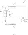
- Fig. 1is a diagrammatic view of a vapour compression system 1 being controlled in accordance with a method according to a first embodiment of the invention.
- the vapour compression system 1comprises a compressor unit 2 comprising one or more compressors 3, one of which is shown, a heat rejecting heat exchanger 4, a high pressure valve 5, a receiver 6, an expansion valve 7 and an evaporator 8 arranged in a refrigerant path.
- Refrigerant flowing in the refrigerant pathis compressed by the compressor 3 before being supplied to the heat rejecting heat exchanger 4.
- heat exchangetakes place between the refrigerant flowing through the heat rejecting heat exchanger 4 and the ambient or a secondary fluid flow across the heat rejecting heat exchanger 4, in such a manner that heat is rejected from the refrigerant.
- the heat rejecting heat exchanger 4is in the form of a condenser, the refrigerant is thereby at least partly condensed.
- the heat rejecting heat exchanger 4is in the form of a gas cooler, the refrigerant flowing through the heat rejecting heat exchanger 4 is cooled, but it remains in a gaseous or trans-critical state.
- the refrigerant leaving the heat rejecting heat exchanger 4is passed through the high pressure valve 5, where it undergoes expansion before being supplied to the receiver 6.
- the refrigerantis separated into a liquid part and a gaseous part.
- the liquid part of the refrigerantleaves the receiver 6 via a liquid outlet 9, and is supplied to the expansion device 7, where it undergoes expansion before being supplied to the evaporator 8.
- the refrigerant being supplied to the evaporator 8is thereby in a mixed gaseous and liquid state.
- the gaseous part of the refrigerant in the receiver 6may be supplied directly to the compressor 3, via a gaseous outlet 10 and a bypass valve 11.
- the vapour compression system 1may be controlled in the following manner.
- a pressure value indicating a pressure prevailing inside the receiveris obtained, e.g. by directly measuring the pressure by means of a pressure sensor arranged inside the receiver 6.
- the obtained pressure valueis then compared to a first threshold pressure value.
- the first threshold pressure valuemay represent a pressure level inside the receiver 6, below which there is a risk that the vapour compression system 1 may not operate in an appropriate manner, because a low pressure inside the receiver 6 may lead to an insufficient supply of refrigerant to the evaporator 8.
- the compressor 3is operated in order to reduce the suction pressure of the vapour compression system 1, i.e. the pressure of refrigerant being supplied to the compressor 3.
- Thismay, e.g., be obtained by increasing the compressor capacity of the compressor unit 2, e.g. by increasing a speed of the compressor 3, or by switching on an additional compressor 3.
- the suction pressuremay be reduced by reducing a suction pressure setpoint value from an initial suction pressure setpoint value, P 0,set , to a reduced suction pressure setpoint value, P 0,red , and then control the compressor 3 based on the reduced suction pressure setpoint value, P 0,red .
- the suction pressuremay once again be increased. This may, e.g., be obtained by restoring the initial suction pressure setpoint value, P 0,set , and then control the compressor 3 based on the restored, initial suction pressure setpoint value, P 0,set .
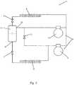
- Fig. 2is a diagrammatic view of a vapour compression system 1 being controlled in accordance with a method according to a second embodiment of the invention.
- the vapour compression system 1 of Fig. 2is very similar to the vapour compression system 1 of Fig. 1 , and it will therefore not be described in detail here.
- the compressor unit 2further comprises a receiver compressor 12 connected to the gaseous outlet 10 of the receiver 6.
- gaseous refrigerant from the receiver 6may be supplied directly to the receiver compressor 12, and may therefore be compressed without having to be mixed with refrigerant leaving the evaporator 8, and thereby without affecting the suction pressure of the vapour compression system 1.
- the vapour compression system 1 of Fig. 2may be controlled essentially as described above with reference to Fig. 1 . Furthermore, the pressure prevailing inside the receiver 6 may be controlled by controlling the receiver compressor 12.
- Fig. 3is a diagrammatic view of a vapour compression system 1 being controlled in accordance with a method according to a third embodiment of the invention.
- the vapour compression system 1 of Fig. 3is very similar to the vapour compression system 1 of Fig. 2 , and it will therefore not be described in detail here.
- the vapour compression system 1 of Fig. 3is not provided with a high pressure valve. Accordingly, the refrigerant leaving the heat rejecting heat exchanger 4 is supplied directly to the receiver 6 without undergoing expansion.
- the vapour compression system 1 of Fig. 3may be controlled essentially as described above with reference to Fig. 1 .
- Fig. 4is a diagrammatic view of a vapour compression system 1 being controlled in accordance with a method according to a fourth embodiment of the invention.
- the vapour compression system 1 of Fig. 4is very similar to the vapour compression system 1 of Fig. 2 , and it will therefore not be described in detail here.
- an ejector 13is arranged fluidly in parallel with the high pressure valve 5. Accordingly, refrigerant leaving the heat rejecting heat exchanger 4 may pass through the high pressure valve 5 or through the ejector 13.
- the ejector 13further has its secondary inlet connected to the outlet of the evaporator 8. Accordingly, refrigerant leaving the evaporator 8 may either be supplied to the compressor 3 or to the ejector 13.
- Fig. 5is a log(P)-h diagram illustrating control of a vapour compression system in accordance with a method according to an embodiment of the invention.
- the vapour compression system being controlledcould, e.g., be one of the vapour compression systems illustrated in Figs. 1-4 .
- the refrigerantis compressed in the compressor unit. Thereby the pressure as well as the enthalpy is increased.
- the refrigerantpasses through the heat rejecting heat exchanger, where heat exchange takes place between the refrigerant and the ambient or a secondary fluid flow across the heat rejecting heat exchanger, in such a manner that heat is rejected from the refrigerant. Thereby the enthalpy is decreased, while the pressure remains constant.
- the refrigerantpasses through a high pressure valve or an ejector, where the refrigerant undergoes expansion, and is received in the receiver. Thereby the pressure is decreased, while the enthalpy remains substantially constant.
- the refrigerantIn the receiver the refrigerant is separated into a liquid part and a gaseous part.
- Point 18represents the liquid part of the refrigerant in the receiver
- point 19represents the gaseous part of the refrigerant in the receiver.
- the liquid part of the refrigerant in the receiveris passed through the expansion device, where it undergoes expansion. Thereby the pressure is reduced while the enthalpy remains constant.
- the refrigerantpasses through the evaporator, where heat exchange takes place between the refrigerant and the ambient or a secondary fluid flow across the evaporator, in such a manner that heat is absorbed by the refrigerant. Thereby the enthalpy is increased, while the pressure remains constant.
- the gaseous part of the refrigerant in the receiveris supplied to the suction line via a bypass valve, and is thereby mixed with refrigerant leaving the evaporator. Passing the refrigerant through the bypass valve causes the pressure to decrease while the enthalpy remains constant.
- the position of the point 17corresponds to the enthalpy of the refrigerant which leaves the heat rejecting heat exchanger and is supplied to the receiver.
- This enthalpydetermines the liquid-vapour ratio of the refrigerant entering the receiver, and the liquid-vapour ratio of the refrigerant entering the receiver has an impact on the pressure prevailing in the receiver.
- the enthalpy of the refrigerant entering the receiveris low, corresponding to the point 17 being arranged far to the left, a large portion of the refrigerant entering the receiver is liquid.
- the liquid-vapour ratio of the refrigerant in the receiver, and thereby the pressure prevailing inside the receivercan be adjusted by adjusting the enthalpy of the refrigerant leaving the heat rejecting heat exchanger.
- Thismay be done by adjusting a secondary fluid flow across the heat rejecting heat exchanger, e.g. by adjusting a fan speed of one or more fans driving this flow. Adjusting the secondary fluid flow has an impact on the heat transfer taking place in the heat rejecting heat exchanger, and this in turn affects the enthalpy of the refrigerant leaving the heat rejecting heat exchanger.
- adjusting a secondary fluid flow across the heat rejecting heat exchangeris one way of controlling the pressure prevailing inside the receiver.
- the liquid-vapour ratio of the refrigerant entering the receivershould be such that at least 5% of the refrigerant is in the form of vapour.
- a certain minimum pressure difference between the pressure prevailing inside the receiver and the suction pressurei.e. the pressure difference across the expansion device, must be maintained.
- This pressure differenceis represented by the difference between the pressure at point 19, representing the pressure prevailing inside the receiver, and the pressure at point 14, representing the suction pressure.
- this pressure differencebecomes too small, it may initially be attempted to increase the pressure prevailing inside the receiver, e.g. in the manner described above. If this is not sufficient to maintain the minimum pressure difference, the suction pressure may be reduced instead. This could, e.g., be done in the manner described above with reference to Fig. 1 .
Landscapes
- Engineering & Computer Science (AREA)
- Physics & Mathematics (AREA)
- Mechanical Engineering (AREA)
- Thermal Sciences (AREA)
- General Engineering & Computer Science (AREA)
- Air Conditioning Control Device (AREA)
Description
- The present invention relates to a method for controlling a vapour compression system comprising a compressor unit, a heat rejecting heat exchanger, a receiver, an expansion device and an evaporator arranged in a refrigerant path. The method according to the invention allows the vapour compression system to operate properly, even when the pressure prevailing inside the receiver is low.
- In vapour compression system refrigerant circulates a refrigerant path having at least a compressor, a heat rejecting heat exchanger, an expansion device and an evaporator arranged therein. Thereby the refrigerant is alternatingly compressed in the compressor and expanded in the expansion device, and heat exchange takes place between the refrigerant and appropriate secondary fluid flows or the ambient in the heat rejecting heat exchanger and the evaporator. Thereby cooling or heating of a closed volume can be obtained.
- In some vapour compression systems a receiver is arranged in the refrigerant path between an outlet of the heat rejecting heat exchanger and an inlet of the expansion device. In this case the refrigerant is separated into a liquid part and a gaseous part in the receiver, and the liquid part of the refrigerant is supplied to the evaporator, via the expansion device. The gaseous part of the refrigerant may be supplied to a compressor. In order to operate such a vapour compression system in an appropriate manner, it is necessary to maintain a pressure level inside the receiver, which is appropriate under the prevailing operating conditions. For instance, when the outdoor temperature is low, such as during winter time, the temperature of refrigerant leaving the heat rejecting heat exchanger is also low. This results in a low pressure inside the receiver.
- When the pressure prevailing inside the receiver is very low, the vapour compression system may not be able to operate properly. For instance, no or an insufficient flow of refrigerant may be supplied to the evaporator, and thereby the heat exchange taking place there will be insufficient, or even non-existent. A very low receiver pressure may even result in a situation where compressors are unable to start, and the vapour compression system will therefore stop operating.
- In order to avoid the situations described above, various measures may be taken in order to control the pressure prevailing inside the receiver to be within a desired range. However, these measures may be insufficient.
WO 2017/067858 A1 discloses a method for controlling a vapour compression system in which a pressure prevailing inside a receiver is controlled in accordance with opening degrees of one or more expansion devices, each being arranged to control a supply of refrigerant to anevaporator EP 3 023 712 A1 discloses a method for controlling a vapour compression system in which a pressure prevailing inside a receiver is controlled by calculating a setpoint value for a pressure inside the receiver and operating the compressor unit in accordance with the calculated setpoint value.- It is an object of embodiments of the invention to provide a method for controlling a vapour compression system which allows the vapour compression system to be operated properly, even when the pressure prevailing inside the receiver is low.
- The invention provides a method for controlling a vapour compression system as defined in
claim 1. The method comprises a compressor unit comprising one or more compressors, a heat rejecting heat exchanger, a receiver, an expansion device and an evaporator arranged in a refrigerant path, the expansion device being arranged to control a supply of refrigerant to the evaporator, the method comprising the steps of: - obtaining a pressure value indicating a pressure prevailing inside the receiver,
- comparing the obtained pressure value to a first threshold pressure value, and
- in the case that the obtained pressure value is below the first threshold pressure value, controlling the compressor(s) of the compressor unit in order to reduce a suction pressure of the vapour compression system.
- Thus, the method according to the invention is for controlling a vapour compression system. In the present context the term 'vapour compression system' should be interpreted to mean any system in which a flow of fluid medium, such as refrigerant, circulates and is alternatingly compressed and expanded, thereby providing either refrigeration or heating of a volume. Thus, the vapour compression system may be a refrigeration system, an air condition system, a heat pump, etc.
- The vapour compression system comprises a compressor unit comprising one or more compressors, a heat rejecting heat exchanger, a receiver, an expansion device and an evaporator arranged in a refrigerant path. The expansion device is arranged to control a supply of refrigerant to the evaporator. The heat rejecting heat exchanger could, e.g., be in the form of a condenser, in which refrigerant is at least partly condensed, or in the form of a gas cooler, in which refrigerant is cooled, but remains in a gaseous or trans-critical state. The expansion device could, e.g., be in the form of an expansion valve.
- Thus, refrigerant flowing in the refrigerant path is compressed by the compressor(s) of the compressor unit. The compressed refrigerant is supplied to the heat rejecting heat exchanger, where heat exchange takes place with the ambient, or with a secondary fluid flow across the heat rejecting heat exchanger, in such a manner that heat is rejected from the refrigerant flowing through the heat rejecting heat exchanger. In the case that the heat rejecting heat exchanger is in the form of a condenser, the refrigerant is at least partly condensed when passing through the heat rejecting heat exchanger. In the case that the heat rejecting heat exchanger is in the form of a gas cooler, the refrigerant flowing through the heat rejecting heat exchanger is cooled, but it remains in a gaseous or trans-critical state.
- From the heat rejecting heat exchanger, the refrigerant is supplied to the receiver, possibly via a high pressure expansion device, such as a high pressure valve or an ejector. In the receiver, the refrigerant is separated into a liquid part and a gaseous part. The liquid part of the refrigerant is supplied to the expansion device, where expansion takes place and the pressure of the refrigerant is reduced, before the refrigerant is supplied to the evaporator. The refrigerant being supplied to the evaporator is thereby in a mixed gaseous and liquid state. In the evaporator, the liquid part of the refrigerant is at least partly evaporated, while heat exchange takes place with the ambient, or with a secondary fluid flow across the evaporator, in such a manner that heat is absorbed by the refrigerant flowing through the evaporator. Finally, the refrigerant is supplied to the compressor unit.
- The gaseous part of the refrigerant in the receiver may be supplied to the compressor unit. Thereby the gaseous part of the refrigerant is not subjected to the pressure drop introduced by the expansion device, and the work required in order to compress the refrigerant can thereby be reduced. Accordingly, energy is conserved.
- According to the method of the invention, a pressure value indicating a pressure prevailing inside the receiver is initially obtained. This could include a direct measurement of the pressure prevailing inside the receiver. As an alternative, the pressure value could be derived from measurements of other parameters, such as measurements of pressure prevailing in other parts of the vapour compression system and/or measurements of temperature prevailing inside the receiver and/or in other parts of the vapour compression system. In any event, the obtained pressure value provides information regarding the current pressure inside the receiver.
- Next, the obtained pressure value is compared to a first threshold pressure value. The first threshold pressure value may represent a pressure level inside the receiver, below which there is a risk that the vapour compression system will operate in an inefficient or inappropriate manner. The first threshold pressure value may be a fixed value, representing a pressure value below which the pressure prevailing inside the receiver should not be allowed to be. Alternatively, the first threshold pressure value may be a dynamical value which can be varied according to the prevailing ambient conditions, such as the outdoor temperature.
- In the case that the comparison reveals that the obtained pressure value is below the first threshold pressure value, this is an indication that the pressure prevailing inside the receiver is approaching a level where there is a risk that the vapour compression system is no longer able to operate in an efficient or appropriate manner. Furthermore, this is an indication that the measures which are normally applied in order to maintain a sufficient pressure level inside the receiver are not sufficient. Therefore, when this situation occurs, the compressor(s) of the compressor unit are controlled in order to reduce a suction pressure of the vapour compression system.
- In the present context the term 'suction pressure' should be interpreted to mean a pressure of refrigerant entering the compressor unit via the part of the refrigerant path which is connected to an outlet of the evaporator.
- When the suction pressure is reduced in this manner, the compressor(s) of the compressor unit will remove more refrigerant from the evaporator, because the pressure difference across the expansion device is increased. This will increase the flow of refrigerant through the evaporator, and thereby the vapour compression system will continue to operate in an appropriate manner, despite the low pressure inside the receiver.
- The step of controlling the compressor(s) of the compressor unit may comprise the steps of:
- reducing a suction pressure setpoint value from an initial suction pressure setpoint value, P0,set, to a reduced suction pressure setpoint value, P0,red, and
- controlling the compressor(s) of the compressor unit based on the reduced suction pressure setpoint value, P0,red.
- According to this embodiment, the compressors of the compressor unit are controlled based on a setpoint value representing a desired suction pressure. This setpoint value may be a fixed value, or it may be variable in accordance with various operating conditions, e.g. according to the pressure prevailing inside the receiver. When a reduction of the suction pressure is required, as described above, the suction pressure setpoint value is lowered from an initial suction pressure setpoint value, P0,set, to a reduced suction pressure setpoint value, P0,red. The initial suction pressure setpoint value, P0,set, represents a suction pressure which is appropriate and desirable under the prevailing operating conditions, i.e. it represents the suction pressure at which the vapour compression system would normally operate, under the given circumstances. The reduced suction pressure setpoint value, P0,red, is a suction pressure value which is lower than the initial suction pressure setpoint value, P0,set, i.e. it is reduced as compared to this value. The reduced suction pressure setpoint value, P0,red, could, e.g., be a fixed amount lower than the initial suction pressure setpoint value, P0,set, which could be a variable according to the operating conditions as described above.
- The compressor(s) of the compressor unit are then controlled based on the reduced suction pressure setpoint value, P0,red, i.e. the compressor(s) are controlled in order to achieve this reduced suction pressure. This will decrease the actual suction pressure from a level corresponding to the initial suction pressure setpoint value, P0,set, to a level corresponding to the reduced suction pressure setpoint value, P0,red, and thereby a reduction in suction pressure is obtained.
- As an alternative, the suction pressure may be reduced in other ways, without changing a setpoint value. For instance, the step of reducing the suction pressure may comprise increasing the compressor capacity of the compressor unit. Such an increase in compressor capacity will also result in a reduced suction pressure. This could, e.g., include overruling the normal control of the compressor unit and/or forcing an additional compressor of the compressor unit to start.
- The method may further comprise the step of adjusting a secondary fluid flow across the heat rejecting heat exchanger, based on the obtained pressure value. The secondary fluid flow across the heat rejecting heat exchanger has an impact on the heat exchange taking place in the heat rejecting heat exchanger. An increase in the secondary fluid flow results in an increased heat transfer from the refrigerant to the secondary fluid, and a decrease in the secondary fluid flow results in a decreased heat transfer from the refrigerant to the secondary fluid flow. Thus, an adjustment of the secondary fluid flow results in an adjustment in the temperature and pressure of the refrigerant leaving the heat rejecting heat exchanger, and this has an impact on the liquid-vapour ratio of the refrigerant being supplied to the receiver. This, in turn, affects the pressure prevailing inside the receiver. Accordingly, the pressure prevailing inside the receiver can be adjusted by appropriately adjusting the secondary fluid flow across the heat rejecting heat exchanger. Thus, adjusting the secondary fluid flow across the heat rejecting heat exchanger is one of the measures which may be taken in order to maintain the pressure prevailing inside the receiver at an appropriate level.
- In the case that the secondary fluid flow across the heat rejecting heat exchanger is an air flow, the secondary fluid flow may be adjusted by adjusting a fan speed of one or more fans driving the secondary fluid flow and/or by switching one or more fans on or off. Alternatively, in the case that the secondary fluid flow is a liquid flow, the secondary fluid flow may be adjusted by adjusting one or more pumps driving the secondary fluid flow.
- The compressor unit may comprise at least one main compressor being fluidly connected to an outlet of the evaporator and at least one receiver compressor being fluidly connected to a gaseous outlet of the receiver, and the method may further comprise the step of controlling the at least one receiver compressor based on the obtained pressure value.
- According to this embodiment, refrigerant leaving the evaporator is supplied to the at least one main compressor, and refrigerant from the gaseous outlet of the receiver is supplied to the at least one receiver compressor. Thus, the receiver compressor removes gaseous refrigerant from the receiver and supplies compressed refrigerant to the heat rejecting heat exchanger. Thus, operating the receiver compressor reduces the pressure prevailing inside the receiver.
- Each of the compressors of the compressor unit may be permanently connected to the outlet of the evaporator or to the gaseous outlet of the receiver. Alternatively, at least some of the compressors may be provided with a valve arrangement allowing the compressor to be selectively connected to the outlet of the evaporator or to the gaseous outlet of the receiver. In this case the available compressor capacity can be distributed in a suitable manner between 'main compressor capacity' and 'receiver compressor capacity', by appropriately operating the valve arrangement(s).
- The supply of refrigerant to the receiver compressor(s) could, e.g., be adjusted by switching one or more compressors between being connected to the outlet of the evaporator and being connected to the gaseous outlet of the receiver. As an alternative, the compressor speed of one or more receiver compressors could be adjusted. As another alternative, one or more receiver compressors could be switched on or off. Finally, the supply of refrigerant to the receiver compressor(s) could be adjusted by controlling a bypass valve arranged in a part of the refrigerant path interconnecting the gaseous outlet of the receiver and the main compressor(s).
- The step of obtaining a pressure value may comprise measuring the pressure prevailing inside the receiver. According to this embodiment, the pressure prevailing inside the receiver is directly measured, e.g. by means of a pressure sensor arranged inside the receiver. As an alternative, the pressure prevailing inside the receiver may be obtained in an indirect manner, e.g. by deriving the pressure from one or more other measured parameters, such as pressures prevailing in other parts of the vapour compression system and/or temperatures prevailing inside the receiver and/or in other parts of the vapour compression system.
- The obtained pressure value may be low pass filtered before being compared to the first threshold pressure value, in order to remove short term fluctuations in the signal.
- The step of controlling the compressor(s) of the compressor unit may comprise adjusting a compressor capacity of the compressor unit. The compressor capacity of the compressor unit affects how much refrigerant is removed from the suction. Accordingly, adjusting the compressor capacity of the compressor unit has an impact on the suction pressure. More particularly, and increase in the compressor capacity results in more refrigerant being removed from the suction line. Thus, the suction pressure is decreased in this case. Similarly, a decrease in the compressor capacity results in less refrigerant being removed from the suction line, and an increase in suction pressure.
- The step of adjusting a compressor capacity of the compressor unit may comprise switching one or more compressors on or off. Switching on a compressor which was previously switched off increases the total compressor capacity by an amount corresponding to the compressor capacity of the compressor being switched on. Similarly, switching off a compressor which was previously switched on decreases the total compressor capacity by an amount corresponding to the compressor capacity of the compressor being switched off. Thus, according to this embodiment, the compressor capacity is adjusted in discrete steps corresponding to the capacities of the available compressors.
- Alternatively or additionally, at least one of the compressors of the compressor unit may be a variable capacity compressor. In this case the step of adjusting a compressor capacity of the compressor unit may comprise varying the compressor capacity of one or more variable capacity compressors, e.g. by varying the speed of one or more compressors.
- The method may further comprise the steps of:
- after controlling the compressor(s) of the compressor unit in order to reduce the suction pressure of the vapour compression system, monitoring the pressure prevailing inside the receiver,
- comparing the monitored pressure prevailing inside the receiver to a second threshold pressure value, and
- in the case that the monitored pressure prevailing inside the receiver is above the second threshold pressure value, controlling the compressor(s) of the compressor unit in order to increase the suction pressure.
- According to this embodiment, when it has been decided to reduce the suction pressure in the manner described above, the pressure prevailing inside the receiver is monitored, e.g. continuously, in order to establish whether or not the low pressure which gave rise to the reduction in suction pressure remains.
- Accordingly, the monitored pressure prevailing inside the receiver is compared to a second threshold pressure value, and in the case that the monitored pressure is above the second threshold pressure value, the compressor(s) of the compressor unit is/are controlled in order to increase the suction pressure.
- The second threshold pressure value may be identical to the first threshold pressure value, in which case the suction pressure will be increased as soon as the pressure prevailing inside the receiver has increased to a level above the first threshold pressure value. However, in most cases the second threshold pressure value is higher than the first threshold pressure value in order to avoid repeatedly switching between reducing and increasing the suction pressure in the case that the pressure prevailing inside the receiver is approximately equal to the first threshold pressure value.
- Thus, according to this embodiment, a reduced suction pressure is only maintained as long as the pressure prevailing inside the receiver is so low that there is a risk that the vapour compression system may not operate in an appropriate manner. As soon as the pressure prevailing inside the receiver has reached a level where this is no longer the case, the suction pressure is once again allowed to increase. This is an advantage because maintaining a low suction pressure requires additional energy consumption, because the compressors of the compressor unit need to work harder. By allowing the suction pressure to increase when the low suction pressure is no longer required, energy is therefore conserved.
- The step of controlling the compressor(s) of the compressor unit in order to increase the suction pressure may comprise increasing a suction pressure setpoint value, e.g. from a reduced suction pressure setpoint value, P0,red, to an initial suction pressure setpoint value, P0,set, i.e. the initial suction pressure setpoint value, P0,set, may be restored. This is similar to reducing the suction pressure by reducing the suction pressure setpoint value described above, and the remarks set forth in this regard are therefore equally applicable here.
- The vapour compression system may further comprise a high pressure expansion device arranged fluidly between an outlet of the heat rejecting heat exchanger and an inlet of the receiver. In this case the refrigerant leaving the heat rejecting heat exchanger undergoes expansion before being supplied to the receiver.
- The high pressure expansion device may be in the form of a high pressure valve, in which case the refrigerant is merely expanded when passing through the high pressure valve.
- As an alternative, the high pressure expansion device may be in the form of an ejector having a primary inlet connected to the outlet of the heat rejecting heat exchanger, an outlet connected to the receiver and a secondary inlet connected to the outlet of the evaporator. Thereby at least some of the refrigerant leaving the evaporator is supplied to the secondary inlet of the ejector. An ejector is a type of pump which uses the Venturi effect to increase the pressure energy of fluid at a suction inlet (or secondary inlet) of the ejector by means of a motive fluid supplied to a motive inlet (or primary inlet) of the ejector. Thereby, arranging an ejector in the refrigerant path as described above will cause the refrigerant to perform work, and thereby the power consumption of the vapour compression system is reduced as compared to the situation where no ejector is provided.
- As another alternative, the high pressure expansion device may comprise at least one high pressure valve and at least one ejector arranged fluidly in parallel.
- In the case that the vapour compression system comprises a high pressure expansion device as described above, a pressure prevailing in the heat rejecting heat exchanger may be controlled by controlling a fluid flow through the high pressure expansion device. This could, e.g., include controlling an opening degree of the high pressure expansion device.
- The invention will now be described in further detail with reference to the accompanying drawings in which
Figs. 1-4 are diagrammatic views of four different vapour compression systems, each being controlled in accordance with a method according to an embodiment of the invention, andFig. 5 is a log(P)-h diagram illustrating control of a vapour compression system in accordance with a method according to an embodiment of the invention.Fig. 1 is a diagrammatic view of avapour compression system 1 being controlled in accordance with a method according to a first embodiment of the invention. Thevapour compression system 1 comprises acompressor unit 2 comprising one ormore compressors 3, one of which is shown, a heat rejectingheat exchanger 4, ahigh pressure valve 5, areceiver 6, an expansion valve 7 and anevaporator 8 arranged in a refrigerant path.- Refrigerant flowing in the refrigerant path is compressed by the
compressor 3 before being supplied to the heat rejectingheat exchanger 4. In the heat rejectingheat exchanger 4, heat exchange takes place between the refrigerant flowing through the heat rejectingheat exchanger 4 and the ambient or a secondary fluid flow across the heat rejectingheat exchanger 4, in such a manner that heat is rejected from the refrigerant. In the case that the heat rejectingheat exchanger 4 is in the form of a condenser, the refrigerant is thereby at least partly condensed. In the case that the heat rejectingheat exchanger 4 is in the form of a gas cooler, the refrigerant flowing through the heat rejectingheat exchanger 4 is cooled, but it remains in a gaseous or trans-critical state. - The refrigerant leaving the heat rejecting
heat exchanger 4 is passed through thehigh pressure valve 5, where it undergoes expansion before being supplied to thereceiver 6. In thereceiver 6, the refrigerant is separated into a liquid part and a gaseous part. The liquid part of the refrigerant leaves thereceiver 6 via aliquid outlet 9, and is supplied to the expansion device 7, where it undergoes expansion before being supplied to theevaporator 8. The refrigerant being supplied to theevaporator 8 is thereby in a mixed gaseous and liquid state. - In the
evaporator 8, heat exchange takes place between the refrigerant flowing through theevaporator 8 and the ambient or a secondary fluid flow across theevaporator 8, in such a manner that heat is absorbed by the refrigerant, while the liquid part of the refrigerant is at least partly evaporated. Finally, the refrigerant leaving theevaporator 8 is once again supplied to thecompressor 3. - The gaseous part of the refrigerant in the
receiver 6 may be supplied directly to thecompressor 3, via agaseous outlet 10 and abypass valve 11. - The
vapour compression system 1 may be controlled in the following manner. A pressure value indicating a pressure prevailing inside the receiver is obtained, e.g. by directly measuring the pressure by means of a pressure sensor arranged inside thereceiver 6. The obtained pressure value is then compared to a first threshold pressure value. The first threshold pressure value may represent a pressure level inside thereceiver 6, below which there is a risk that thevapour compression system 1 may not operate in an appropriate manner, because a low pressure inside thereceiver 6 may lead to an insufficient supply of refrigerant to theevaporator 8. - In the case that the comparison reveals that the obtained pressure value is below the first threshold pressure value, the
compressor 3 is operated in order to reduce the suction pressure of thevapour compression system 1, i.e. the pressure of refrigerant being supplied to thecompressor 3. This may, e.g., be obtained by increasing the compressor capacity of thecompressor unit 2, e.g. by increasing a speed of thecompressor 3, or by switching on anadditional compressor 3. Alternatively, the suction pressure may be reduced by reducing a suction pressure setpoint value from an initial suction pressure setpoint value, P0,set, to a reduced suction pressure setpoint value, P0,red, and then control thecompressor 3 based on the reduced suction pressure setpoint value, P0,red. - In the case that it is subsequently revealed that the pressure prevailing inside the
receiver 6 has increased to a level where there is no longer a risk that thevapour compression system 1 may not operate in an appropriate manner, the suction pressure may once again be increased. This may, e.g., be obtained by restoring the initial suction pressure setpoint value, P0,set, and then control thecompressor 3 based on the restored, initial suction pressure setpoint value, P0,set. Fig. 2 is a diagrammatic view of avapour compression system 1 being controlled in accordance with a method according to a second embodiment of the invention. Thevapour compression system 1 ofFig. 2 is very similar to thevapour compression system 1 ofFig. 1 , and it will therefore not be described in detail here.- In the
vapour compression system 1 ofFig. 2 thecompressor unit 2 further comprises areceiver compressor 12 connected to thegaseous outlet 10 of thereceiver 6. Thereby gaseous refrigerant from thereceiver 6 may be supplied directly to thereceiver compressor 12, and may therefore be compressed without having to be mixed with refrigerant leaving theevaporator 8, and thereby without affecting the suction pressure of thevapour compression system 1. - The
vapour compression system 1 ofFig. 2 may be controlled essentially as described above with reference toFig. 1 . Furthermore, the pressure prevailing inside thereceiver 6 may be controlled by controlling thereceiver compressor 12. Fig. 3 is a diagrammatic view of avapour compression system 1 being controlled in accordance with a method according to a third embodiment of the invention. Thevapour compression system 1 ofFig. 3 is very similar to thevapour compression system 1 ofFig. 2 , and it will therefore not be described in detail here.- The
vapour compression system 1 ofFig. 3 is not provided with a high pressure valve. Accordingly, the refrigerant leaving the heat rejectingheat exchanger 4 is supplied directly to thereceiver 6 without undergoing expansion. Thevapour compression system 1 ofFig. 3 may be controlled essentially as described above with reference toFig. 1 . Fig. 4 is a diagrammatic view of avapour compression system 1 being controlled in accordance with a method according to a fourth embodiment of the invention. Thevapour compression system 1 ofFig. 4 is very similar to thevapour compression system 1 ofFig. 2 , and it will therefore not be described in detail here.- In the
vapour compression system 1 ofFig. 4 , anejector 13 is arranged fluidly in parallel with thehigh pressure valve 5. Accordingly, refrigerant leaving the heat rejectingheat exchanger 4 may pass through thehigh pressure valve 5 or through theejector 13. Theejector 13 further has its secondary inlet connected to the outlet of theevaporator 8. Accordingly, refrigerant leaving theevaporator 8 may either be supplied to thecompressor 3 or to theejector 13. Fig. 5 is a log(P)-h diagram illustrating control of a vapour compression system in accordance with a method according to an embodiment of the invention. The vapour compression system being controlled could, e.g., be one of the vapour compression systems illustrated inFigs. 1-4 . Frompoint 14 to point 15 the refrigerant is compressed in the compressor unit. Thereby the pressure as well as the enthalpy is increased. Frompoint 15 to point 16 the refrigerant passes through the heat rejecting heat exchanger, where heat exchange takes place between the refrigerant and the ambient or a secondary fluid flow across the heat rejecting heat exchanger, in such a manner that heat is rejected from the refrigerant. Thereby the enthalpy is decreased, while the pressure remains constant.- From
point 16 to point 17 the refrigerant passes through a high pressure valve or an ejector, where the refrigerant undergoes expansion, and is received in the receiver. Thereby the pressure is decreased, while the enthalpy remains substantially constant. - In the receiver the refrigerant is separated into a liquid part and a gaseous part.
Point 18 represents the liquid part of the refrigerant in the receiver, andpoint 19 represents the gaseous part of the refrigerant in the receiver. Frompoint 18 to point 20 the liquid part of the refrigerant in the receiver is passed through the expansion device, where it undergoes expansion. Thereby the pressure is reduced while the enthalpy remains constant. Frompoint 20 to point 14 the refrigerant passes through the evaporator, where heat exchange takes place between the refrigerant and the ambient or a secondary fluid flow across the evaporator, in such a manner that heat is absorbed by the refrigerant. Thereby the enthalpy is increased, while the pressure remains constant. - From
point 19 to point 14 the gaseous part of the refrigerant in the receiver is supplied to the suction line via a bypass valve, and is thereby mixed with refrigerant leaving the evaporator. Passing the refrigerant through the bypass valve causes the pressure to decrease while the enthalpy remains constant. - The position of the
point 17 corresponds to the enthalpy of the refrigerant which leaves the heat rejecting heat exchanger and is supplied to the receiver. This enthalpy determines the liquid-vapour ratio of the refrigerant entering the receiver, and the liquid-vapour ratio of the refrigerant entering the receiver has an impact on the pressure prevailing in the receiver. Thus, when the enthalpy of the refrigerant entering the receiver is low, corresponding to thepoint 17 being arranged far to the left, a large portion of the refrigerant entering the receiver is liquid. Similarly, when the enthalpy of the refrigerant entering the receiver is high, corresponding to thepoint 17 being arranged far to the right, a large portion of the refrigerant entering the receiver is gaseous, i.e. in the form of vapour. - Accordingly, the liquid-vapour ratio of the refrigerant in the receiver, and thereby the pressure prevailing inside the receiver, can be adjusted by adjusting the enthalpy of the refrigerant leaving the heat rejecting heat exchanger. This may be done by adjusting a secondary fluid flow across the heat rejecting heat exchanger, e.g. by adjusting a fan speed of one or more fans driving this flow. Adjusting the secondary fluid flow has an impact on the heat transfer taking place in the heat rejecting heat exchanger, and this in turn affects the enthalpy of the refrigerant leaving the heat rejecting heat exchanger.
- Thus, adjusting a secondary fluid flow across the heat rejecting heat exchanger is one way of controlling the pressure prevailing inside the receiver. Preferably, the liquid-vapour ratio of the refrigerant entering the receiver should be such that at least 5% of the refrigerant is in the form of vapour.
- Furthermore, in order to ensure a sufficient refrigerant supply to the evaporator, a certain minimum pressure difference between the pressure prevailing inside the receiver and the suction pressure, i.e. the pressure difference across the expansion device, must be maintained. This pressure difference is represented by the difference between the pressure at
point 19, representing the pressure prevailing inside the receiver, and the pressure atpoint 14, representing the suction pressure. - In the case that this pressure difference becomes too small, it may initially be attempted to increase the pressure prevailing inside the receiver, e.g. in the manner described above. If this is not sufficient to maintain the minimum pressure difference, the suction pressure may be reduced instead. This could, e.g., be done in the manner described above with reference to
Fig. 1 .
Claims (9)
- A method for controlling a vapour compression system (1) comprising a compressor unit (2) comprising one or more compressors (3, 12), a heat rejecting heat exchanger (4), a receiver (6), an expansion device (7) and an evaporator (8) arranged in a refrigerant path, the expansion device (7) being arranged to control a supply of refrigerant to the evaporator (8), the method comprising the steps of:- obtaining a pressure value indicating a pressure prevailing inside the receiver (6),- comparing the obtained pressure value to a first threshold pressure value, and- in the case that the obtained pressure value is below the first threshold pressure value, controlling the compressor(s) (3, 12) of the compressor unit (2) in order to reduce a suction pressure of the vapour compression system (1).
- A method according to claim 1, wherein the step of controlling the compressor(s) (3, 12) of the compressor unit (2) comprises the steps of:- reducing a suction pressure setpoint value from an initial suction pressure setpoint value, P0,set, to a reduced suction pressure setpoint value, P0,red, and- controlling the compressor(s) (3, 12) of the compressor unit (2) based on the reduced suction pressure setpoint value, P0,red.
- A method according to claim 1, wherein the step of reducing the suction pressure comprises increasing the compressor capacity of the compressor unit (2).
- A method according to any of the preceding claims, further comprising the step of adjusting a secondary fluid flow across the heat rejecting heat exchanger (4), based on the obtained pressure value.
- A method according to any of the preceding claims, wherein the compressor unit (2) comprises at least one main compressor (3) being fluidly connected to an outlet of the evaporator (8) and at least one receiver compressor (12) being fluidly connected to a gaseous outlet (10) of the receiver (6), and wherein the method further comprises the step of controlling the at least one receiver compressor (12) based on the obtained pressure value.
- A method according to any of the preceding claims, wherein the step of obtaining a pressure value comprises measuring the pressure prevailing inside the receiver (6).
- A method according to any of the preceding claims, wherein the step of controlling the compressor(s) (3, 12) of the compressor unit (2) comprises adjusting a compressor capacity of the compressor unit (2).
- A method according to claim 7, wherein the step of adjusting a compressor capacity of the compressor unit (2) comprises switching one or more compressors (3, 12) on or off.
- A method according to any of the preceding claims, further comprising the steps of:- after controlling the compressor(s) (3, 12) of the compressor unit (2) in order to reduce the suction pressure of the vapour compression system (1), monitoring the pressure prevailing inside the receiver (6),- comparing the monitored pressure prevailing inside the receiver (6) to a second threshold pressure value, and- in the case that the monitored pressure prevailing inside the receiver (6) is above the second threshold pressure value, controlling the compressor(s) (3, 12) of the compressor unit (2) in order to increase the suction pressure.
Priority Applications (5)
| Application Number | Priority Date | Filing Date | Title |
|---|---|---|---|
| EP18196411.5AEP3628942B1 (en) | 2018-09-25 | 2018-09-25 | A method for controlling a vapour compression system at a reduced suction pressure |
| PL18196411TPL3628942T3 (en) | 2018-09-25 | 2018-09-25 | A method for controlling a vapour compression system at a reduced suction pressure |
| US17/278,738US11959676B2 (en) | 2018-09-25 | 2019-09-12 | Method for controlling a vapour compression system at a reduced suction pressure |
| CN201980050556.2ACN112534196B (en) | 2018-09-25 | 2019-09-12 | Method for controlling a vapour compression system at reduced suction pressure |
| PCT/EP2019/074352WO2020064351A1 (en) | 2018-09-25 | 2019-09-12 | A method for controlling a vapour compression system at a reduced suction pressure |
Applications Claiming Priority (1)
| Application Number | Priority Date | Filing Date | Title |
|---|---|---|---|
| EP18196411.5AEP3628942B1 (en) | 2018-09-25 | 2018-09-25 | A method for controlling a vapour compression system at a reduced suction pressure |
Publications (2)
| Publication Number | Publication Date |
|---|---|
| EP3628942A1 EP3628942A1 (en) | 2020-04-01 |
| EP3628942B1true EP3628942B1 (en) | 2021-01-27 |
Family
ID=63683666
Family Applications (1)
| Application Number | Title | Priority Date | Filing Date |
|---|---|---|---|
| EP18196411.5AActiveEP3628942B1 (en) | 2018-09-25 | 2018-09-25 | A method for controlling a vapour compression system at a reduced suction pressure |
Country Status (5)
| Country | Link |
|---|---|
| US (1) | US11959676B2 (en) |
| EP (1) | EP3628942B1 (en) |
| CN (1) | CN112534196B (en) |
| PL (1) | PL3628942T3 (en) |
| WO (1) | WO2020064351A1 (en) |
Families Citing this family (2)
| Publication number | Priority date | Publication date | Assignee | Title |
|---|---|---|---|---|
| EP4016207B1 (en)* | 2020-12-18 | 2023-01-04 | Danfoss A/S | A method for configuring setpoints for a vapour compression system |
| CN113566455B (en)* | 2021-08-18 | 2023-04-07 | 深圳市蓝石环保科技有限公司 | Heat pump system, control method, electronic device, and evaporation processing system |
Family Cites Families (67)
| Publication number | Priority date | Publication date | Assignee | Title |
|---|---|---|---|---|
| US4227862A (en) | 1978-09-19 | 1980-10-14 | Frick Company | Solid state compressor control system |
| US5867995A (en)* | 1995-07-14 | 1999-02-09 | Energy Controls International, Inc. | Electronic control of refrigeration systems |
| US6321564B1 (en) | 1999-03-15 | 2001-11-27 | Denso Corporation | Refrigerant cycle system with expansion energy recovery |
| JP3966044B2 (en) | 2002-04-02 | 2007-08-29 | 株式会社デンソー | Air conditioner |
| JP2004293813A (en) | 2003-03-25 | 2004-10-21 | Sanyo Electric Co Ltd | Refrigerant cycle device |
| JP2004354017A (en) | 2003-05-30 | 2004-12-16 | Sanyo Electric Co Ltd | Cooling device |
| TWI309290B (en) | 2003-05-30 | 2009-05-01 | Sanyo Electric Co | Cooling apparatus |
| JP4179927B2 (en) | 2003-06-04 | 2008-11-12 | 三洋電機株式会社 | Method for setting refrigerant filling amount of cooling device |
| EP1701112B1 (en) | 2003-11-28 | 2017-11-15 | Mitsubishi Denki Kabushiki Kaisha | Freezer and air conditioner |
| US7389648B2 (en) | 2004-03-04 | 2008-06-24 | Carrier Corporation | Pressure regulation in a transcritical refrigerant cycle |
| DE102004038640A1 (en) | 2004-08-09 | 2006-02-23 | Linde Kältetechnik GmbH & Co. KG | Refrigeration circuit and method for operating a refrigeration cycle |
| US20080196420A1 (en) | 2004-08-09 | 2008-08-21 | Andreas Gernemann | Flashgas Removal From a Receiver in a Refrigeration Circuit |
| JP2006343017A (en) | 2005-06-08 | 2006-12-21 | Sanyo Electric Co Ltd | Freezer |
| EP2005079B1 (en) | 2006-03-27 | 2016-12-07 | Carrier Corporation | Refrigerating system with parallel staged economizer circuits and a single or two stage main compressor |
| EP1974171B1 (en) | 2006-09-29 | 2014-07-23 | Carrier Corporation | Refrigerant vapor compression system with flash tank receiver |
| DE102006050232B9 (en) | 2006-10-17 | 2008-09-18 | Bitzer Kühlmaschinenbau Gmbh | refrigeration plant |
| US8561425B2 (en) | 2007-04-24 | 2013-10-22 | Carrier Corporation | Refrigerant vapor compression system with dual economizer circuits |
| EP2147269A4 (en) | 2007-04-24 | 2014-05-28 | Carrier Corp | Transcritical refrigerant vapor compression system with charge management |
| EP2147264B1 (en) | 2007-04-24 | 2019-01-16 | Carrier Corporation | Refrigerant vapor compression system |
| JP2009014210A (en) | 2007-06-29 | 2009-01-22 | Daikin Ind Ltd | Refrigeration equipment |
| EP2203693B1 (en) | 2007-09-24 | 2019-10-30 | Carrier Corporation | Refrigerant system with bypass line and dedicated economized flow compression chamber |
| CN101809384B (en) | 2007-09-28 | 2012-12-12 | 开利公司 | Refrigerant circuit and method for managing oil therein |
| EP2229564A4 (en) | 2008-01-17 | 2014-01-15 | Carrier Corp | Mounting of pressure relief devices in a high pressure refrigeration system |
| US9951975B2 (en) | 2008-01-17 | 2018-04-24 | Carrier Corporation | Carbon dioxide refrigerant vapor compression system |
| EP2245392B1 (en) | 2008-01-17 | 2019-09-18 | Carrier Corporation | Pressure relief in high pressure refrigeration system |
| JP5181813B2 (en) | 2008-05-02 | 2013-04-10 | ダイキン工業株式会社 | Refrigeration equipment |
| JP5025605B2 (en) | 2008-09-12 | 2012-09-12 | 三菱電機株式会社 | Refrigeration cycle apparatus and air conditioner |
| EP2329206B1 (en) | 2008-09-29 | 2016-10-19 | Carrier Corporation | Flash tank economizer cycle control |
| US20110174014A1 (en) | 2008-10-01 | 2011-07-21 | Carrier Corporation | Liquid vapor separation in transcritical refrigerant cycle |
| US10088202B2 (en) | 2009-10-23 | 2018-10-02 | Carrier Corporation | Refrigerant vapor compression system operation |
| WO2011049778A1 (en) | 2009-10-23 | 2011-04-28 | Carrier Corporation | Parameter control in transport refrigeration system and methods for same |
| DK2339265T3 (en) | 2009-12-25 | 2018-05-28 | Sanyo Electric Co | Cooling device |
| DK2339266T3 (en) | 2009-12-25 | 2018-05-28 | Sanyo Electric Co | Cooling device |
| US9909786B2 (en) | 2010-03-08 | 2018-03-06 | Carrier Corporation | Refrigerant distribution apparatus and methods for transport refrigeration system |
| EP2565555B1 (en) | 2010-04-27 | 2021-04-21 | Mitsubishi Electric Corporation | Refrigeration cycle apparatus |
| DK2649387T3 (en) | 2010-12-08 | 2018-11-12 | Carrier Corp | CYCLE FOR COOLING |
| DK2673585T3 (en) | 2011-02-08 | 2019-03-25 | Carrier Corp | HARDWOOD PLATE HEAT EXCHANGE FOR WATER COOLED HEAT REJECTION IN COOLING CYCLE |
| CN103717981B (en) | 2011-07-26 | 2016-08-17 | 开利公司 | Temperature control logic for refrigeration systems |
| US9395105B2 (en) | 2011-09-01 | 2016-07-19 | Mitsubishi Electric Corporation | Refrigeration cycle device |
| JP5944135B2 (en) | 2011-10-17 | 2016-07-05 | サンデンホールディングス株式会社 | Air conditioner for vehicles |
| MX359679B (en) | 2011-11-21 | 2018-10-05 | Hill Phoenix Inc | C02 refrigeration system with hot gas defrost. |
| WO2013169591A1 (en) | 2012-05-11 | 2013-11-14 | Hill Phoenix, Inc. | Co2 refrigeration system with integrated air conditioning module |
| FR2992913B1 (en) | 2012-07-03 | 2014-08-08 | Air Liquide | METHOD AND APPARATUS FOR REFRIGERATED TRANSPORT USING INDIRECT INJECTION OF A CRYOGENIC LIQUID AND PROVIDING A TEMPERATURE HOLDING SOLUTION IN THE CASE OF VERY LOW EXTERIOR TEMPERATURES |
| EP2888542A1 (en) | 2012-08-24 | 2015-07-01 | Carrier Corporation | Transcritical refrigerant vapor compression system high side pressure control |
| WO2014031708A1 (en) | 2012-08-24 | 2014-02-27 | Carrier Corporation | Stage transition in transcritical refrigerant vapor compression system |
| BR112015017772A2 (en)* | 2013-01-25 | 2017-07-11 | Emerson Climate Tech Retail Solutions Inc | system and method for transcritical refrigeration system control |
| US9353980B2 (en)* | 2013-05-02 | 2016-05-31 | Emerson Climate Technologies, Inc. | Climate-control system having multiple compressors |
| EP3339769B1 (en) | 2013-05-03 | 2024-08-21 | Hill Phoenix Inc. | Systems and methods for pressure control in a co2 refrigeration system |
| US20160231040A1 (en) | 2013-09-19 | 2016-08-11 | Carrier Corporation | Refrigeration circuit with heat recovery module |
| US20160298883A1 (en) | 2013-11-14 | 2016-10-13 | Parker-Hannifin Corporation | System and method for controlling fluid flow and temperature within a pumped two-phase cooling distribution unit |
| ES2792508T3 (en) | 2014-07-09 | 2020-11-11 | Carrier Corp | Refrigeration system |
| US9746213B2 (en) | 2014-08-14 | 2017-08-29 | Siemens Industry, Inc | Demand flow for air cooled chillers |
| EP3023712A1 (en) | 2014-11-19 | 2016-05-25 | Danfoss A/S | A method for controlling a vapour compression system with a receiver |
| EP3023713A1 (en)* | 2014-11-19 | 2016-05-25 | Danfoss A/S | A method for controlling a vapour compression system with an ejector |
| EP3054238B1 (en)* | 2015-02-03 | 2021-03-24 | Rolls-Royce Corporation | Charge control system for trans-critical vapor cycle systems |
| CN107532827B (en) | 2015-05-12 | 2021-06-08 | 开利公司 | Ejector refrigeration circuit |
| WO2016198258A1 (en) | 2015-06-08 | 2016-12-15 | Danfoss A/S | A method for operating a vapour compression system with heat recovery |
| EP3341662B1 (en) | 2015-08-03 | 2024-06-05 | Hill Phoenix Inc. | Co2 refrigeration system with direct co2 heat exchange |
| PL3365620T3 (en) | 2015-10-20 | 2020-01-31 | Danfoss A/S | A method for controlling a vapour compression system in a flooded state |
| US11460230B2 (en) | 2015-10-20 | 2022-10-04 | Danfoss A/S | Method for controlling a vapour compression system with a variable receiver pressure setpoint |
| EP3371523B1 (en) | 2015-11-05 | 2020-05-06 | Danfoss A/S | A method for switching compressor capacity |
| WO2017220702A1 (en) | 2016-06-24 | 2017-12-28 | Danfoss A/S | A method for controlling pressure and oil level in an oil receiver of a vapour compressions system |
| US10962262B2 (en)* | 2016-11-22 | 2021-03-30 | Danfoss A/S | Method for controlling a vapour compression system during gas bypass valve malfunction |
| US10208985B2 (en) | 2016-12-30 | 2019-02-19 | Heatcraft Refrigeration Products Llc | Flash tank pressure control for transcritical system with ejector(s) |
| US10496108B2 (en) | 2017-07-19 | 2019-12-03 | Heatcraft Refrigeration Products Llc | Cooling system flood prevention tool |
| US11353246B2 (en) | 2018-06-11 | 2022-06-07 | Hill Phoenix, Inc. | CO2 refrigeration system with automated control optimization |
| EP3798533B1 (en) | 2019-09-26 | 2022-04-20 | Danfoss A/S | A method for controlling suction pressure of a vapour compression system |
- 2018
- 2018-09-25EPEP18196411.5Apatent/EP3628942B1/enactiveActive
- 2018-09-25PLPL18196411Tpatent/PL3628942T3/enunknown
- 2019
- 2019-09-12CNCN201980050556.2Apatent/CN112534196B/enactiveActive
- 2019-09-12USUS17/278,738patent/US11959676B2/enactiveActive
- 2019-09-12WOPCT/EP2019/074352patent/WO2020064351A1/ennot_activeCeased
Also Published As
| Publication number | Publication date |
|---|---|
| CN112534196A (en) | 2021-03-19 |
| PL3628942T3 (en) | 2021-10-04 |
| EP3628942A1 (en) | 2020-04-01 |
| WO2020064351A1 (en) | 2020-04-02 |
| CN112534196B (en) | 2022-01-11 |
| US11959676B2 (en) | 2024-04-16 |
| US20220034567A1 (en) | 2022-02-03 |
Similar Documents
| Publication | Publication Date | Title |
|---|---|---|
| EP3023714B1 (en) | A method for controlling a vapour compression system with an ejector | |
| EP3032192B1 (en) | A method for controlling a valve arrangement in a vapour compression system | |
| EP3365618B1 (en) | A method for controlling a vapour compression system with a variable receiver pressure setpoint | |
| EP3365619B1 (en) | A method for controlling a vapour compression system in ejector mode for a prolonged time | |
| US8701424B2 (en) | Turbo chiller, heat source system, and method for controlling the same | |
| EP3545243B1 (en) | A method for controlling a vapour compression system during gas bypass valve malfunction | |
| CA2997662A1 (en) | A method for controlling a vapour compression system in a flooded state | |
| EP3798533B1 (en) | A method for controlling suction pressure of a vapour compression system | |
| EP3545242B1 (en) | A method for controlling a vapour compression system during gas bypass valve malfunction | |
| US11959676B2 (en) | Method for controlling a vapour compression system at a reduced suction pressure | |
| EP3601907B1 (en) | A vapour compression system with a suction line liquid separator | |
| EP3628940B1 (en) | A method for controlling a vapour compression system based on estimated flow |
Legal Events
| Date | Code | Title | Description |
|---|---|---|---|
| PUAI | Public reference made under article 153(3) epc to a published international application that has entered the european phase | Free format text:ORIGINAL CODE: 0009012 | |
| STAA | Information on the status of an ep patent application or granted ep patent | Free format text:STATUS: THE APPLICATION HAS BEEN PUBLISHED | |
| AK | Designated contracting states | Kind code of ref document:A1 Designated state(s):AL AT BE BG CH CY CZ DE DK EE ES FI FR GB GR HR HU IE IS IT LI LT LU LV MC MK MT NL NO PL PT RO RS SE SI SK SM TR | |
| AX | Request for extension of the european patent | Extension state:BA ME | |
| STAA | Information on the status of an ep patent application or granted ep patent | Free format text:STATUS: REQUEST FOR EXAMINATION WAS MADE | |
| 17P | Request for examination filed | Effective date:20200901 | |
| RBV | Designated contracting states (corrected) | Designated state(s):AL AT BE BG CH CY CZ DE DK EE ES FI FR GB GR HR HU IE IS IT LI LT LU LV MC MK MT NL NO PL PT RO RS SE SI SK SM TR | |
| GRAP | Despatch of communication of intention to grant a patent | Free format text:ORIGINAL CODE: EPIDOSNIGR1 | |
| STAA | Information on the status of an ep patent application or granted ep patent | Free format text:STATUS: GRANT OF PATENT IS INTENDED | |
| GRAS | Grant fee paid | Free format text:ORIGINAL CODE: EPIDOSNIGR3 | |
| INTG | Intention to grant announced | Effective date:20201117 | |
| GRAA | (expected) grant | Free format text:ORIGINAL CODE: 0009210 | |
| STAA | Information on the status of an ep patent application or granted ep patent | Free format text:STATUS: THE PATENT HAS BEEN GRANTED | |
| AK | Designated contracting states | Kind code of ref document:B1 Designated state(s):AL AT BE BG CH CY CZ DE DK EE ES FI FR GB GR HR HU IE IS IT LI LT LU LV MC MK MT NL NO PL PT RO RS SE SI SK SM TR | |
| REG | Reference to a national code | Ref country code:GB Ref legal event code:FG4D | |
| REG | Reference to a national code | Ref country code:CH Ref legal event code:EP | |
| REG | Reference to a national code | Ref country code:AT Ref legal event code:REF Ref document number:1358711 Country of ref document:AT Kind code of ref document:T Effective date:20210215 | |
| REG | Reference to a national code | Ref country code:IE Ref legal event code:FG4D | |
| REG | Reference to a national code | Ref country code:DE Ref legal event code:R096 Ref document number:602018012226 Country of ref document:DE | |
| REG | Reference to a national code | Ref country code:NL Ref legal event code:MP Effective date:20210127 | |
| REG | Reference to a national code | Ref country code:LT Ref legal event code:MG9D | |
| REG | Reference to a national code | Ref country code:AT Ref legal event code:MK05 Ref document number:1358711 Country of ref document:AT Kind code of ref document:T Effective date:20210127 | |
| PG25 | Lapsed in a contracting state [announced via postgrant information from national office to epo] | Ref country code:HR Free format text:LAPSE BECAUSE OF FAILURE TO SUBMIT A TRANSLATION OF THE DESCRIPTION OR TO PAY THE FEE WITHIN THE PRESCRIBED TIME-LIMIT Effective date:20210127 Ref country code:FI Free format text:LAPSE BECAUSE OF FAILURE TO SUBMIT A TRANSLATION OF THE DESCRIPTION OR TO PAY THE FEE WITHIN THE PRESCRIBED TIME-LIMIT Effective date:20210127 Ref country code:GR Free format text:LAPSE BECAUSE OF FAILURE TO SUBMIT A TRANSLATION OF THE DESCRIPTION OR TO PAY THE FEE WITHIN THE PRESCRIBED TIME-LIMIT Effective date:20210428 Ref country code:BG Free format text:LAPSE BECAUSE OF FAILURE TO SUBMIT A TRANSLATION OF THE DESCRIPTION OR TO PAY THE FEE WITHIN THE PRESCRIBED TIME-LIMIT Effective date:20210427 Ref country code:NO Free format text:LAPSE BECAUSE OF FAILURE TO SUBMIT A TRANSLATION OF THE DESCRIPTION OR TO PAY THE FEE WITHIN THE PRESCRIBED TIME-LIMIT Effective date:20210427 Ref country code:PT Free format text:LAPSE BECAUSE OF FAILURE TO SUBMIT A TRANSLATION OF THE DESCRIPTION OR TO PAY THE FEE WITHIN THE PRESCRIBED TIME-LIMIT Effective date:20210527 Ref country code:LT Free format text:LAPSE BECAUSE OF FAILURE TO SUBMIT A TRANSLATION OF THE DESCRIPTION OR TO PAY THE FEE WITHIN THE PRESCRIBED TIME-LIMIT Effective date:20210127 | |
| PG25 | Lapsed in a contracting state [announced via postgrant information from national office to epo] | Ref country code:LV Free format text:LAPSE BECAUSE OF FAILURE TO SUBMIT A TRANSLATION OF THE DESCRIPTION OR TO PAY THE FEE WITHIN THE PRESCRIBED TIME-LIMIT Effective date:20210127 Ref country code:RS Free format text:LAPSE BECAUSE OF FAILURE TO SUBMIT A TRANSLATION OF THE DESCRIPTION OR TO PAY THE FEE WITHIN THE PRESCRIBED TIME-LIMIT Effective date:20210127 Ref country code:AT Free format text:LAPSE BECAUSE OF FAILURE TO SUBMIT A TRANSLATION OF THE DESCRIPTION OR TO PAY THE FEE WITHIN THE PRESCRIBED TIME-LIMIT Effective date:20210127 Ref country code:SE Free format text:LAPSE BECAUSE OF FAILURE TO SUBMIT A TRANSLATION OF THE DESCRIPTION OR TO PAY THE FEE WITHIN THE PRESCRIBED TIME-LIMIT Effective date:20210127 | |
| PG25 | Lapsed in a contracting state [announced via postgrant information from national office to epo] | Ref country code:IS Free format text:LAPSE BECAUSE OF FAILURE TO SUBMIT A TRANSLATION OF THE DESCRIPTION OR TO PAY THE FEE WITHIN THE PRESCRIBED TIME-LIMIT Effective date:20210527 | |
| REG | Reference to a national code | Ref country code:DE Ref legal event code:R097 Ref document number:602018012226 Country of ref document:DE | |
| PG25 | Lapsed in a contracting state [announced via postgrant information from national office to epo] | Ref country code:EE Free format text:LAPSE BECAUSE OF FAILURE TO SUBMIT A TRANSLATION OF THE DESCRIPTION OR TO PAY THE FEE WITHIN THE PRESCRIBED TIME-LIMIT Effective date:20210127 Ref country code:CZ Free format text:LAPSE BECAUSE OF FAILURE TO SUBMIT A TRANSLATION OF THE DESCRIPTION OR TO PAY THE FEE WITHIN THE PRESCRIBED TIME-LIMIT Effective date:20210127 Ref country code:SM Free format text:LAPSE BECAUSE OF FAILURE TO SUBMIT A TRANSLATION OF THE DESCRIPTION OR TO PAY THE FEE WITHIN THE PRESCRIBED TIME-LIMIT Effective date:20210127 | |
| PG25 | Lapsed in a contracting state [announced via postgrant information from national office to epo] | Ref country code:DK Free format text:LAPSE BECAUSE OF FAILURE TO SUBMIT A TRANSLATION OF THE DESCRIPTION OR TO PAY THE FEE WITHIN THE PRESCRIBED TIME-LIMIT Effective date:20210127 Ref country code:SK Free format text:LAPSE BECAUSE OF FAILURE TO SUBMIT A TRANSLATION OF THE DESCRIPTION OR TO PAY THE FEE WITHIN THE PRESCRIBED TIME-LIMIT Effective date:20210127 Ref country code:RO Free format text:LAPSE BECAUSE OF FAILURE TO SUBMIT A TRANSLATION OF THE DESCRIPTION OR TO PAY THE FEE WITHIN THE PRESCRIBED TIME-LIMIT Effective date:20210127 | |
| PLBE | No opposition filed within time limit | Free format text:ORIGINAL CODE: 0009261 | |
| STAA | Information on the status of an ep patent application or granted ep patent | Free format text:STATUS: NO OPPOSITION FILED WITHIN TIME LIMIT | |
| 26N | No opposition filed | Effective date:20211028 | |
| PG25 | Lapsed in a contracting state [announced via postgrant information from national office to epo] | Ref country code:AL Free format text:LAPSE BECAUSE OF FAILURE TO SUBMIT A TRANSLATION OF THE DESCRIPTION OR TO PAY THE FEE WITHIN THE PRESCRIBED TIME-LIMIT Effective date:20210127 Ref country code:ES Free format text:LAPSE BECAUSE OF FAILURE TO SUBMIT A TRANSLATION OF THE DESCRIPTION OR TO PAY THE FEE WITHIN THE PRESCRIBED TIME-LIMIT Effective date:20210127 | |
| PG25 | Lapsed in a contracting state [announced via postgrant information from national office to epo] | Ref country code:SI Free format text:LAPSE BECAUSE OF FAILURE TO SUBMIT A TRANSLATION OF THE DESCRIPTION OR TO PAY THE FEE WITHIN THE PRESCRIBED TIME-LIMIT Effective date:20210127 | |
| REG | Reference to a national code | Ref country code:CH Ref legal event code:PL | |
| REG | Reference to a national code | Ref country code:BE Ref legal event code:MM Effective date:20210930 | |
| PG25 | Lapsed in a contracting state [announced via postgrant information from national office to epo] | Ref country code:IS Free format text:LAPSE BECAUSE OF FAILURE TO SUBMIT A TRANSLATION OF THE DESCRIPTION OR TO PAY THE FEE WITHIN THE PRESCRIBED TIME-LIMIT Effective date:20210527 Ref country code:MC Free format text:LAPSE BECAUSE OF FAILURE TO SUBMIT A TRANSLATION OF THE DESCRIPTION OR TO PAY THE FEE WITHIN THE PRESCRIBED TIME-LIMIT Effective date:20210127 | |
| PG25 | Lapsed in a contracting state [announced via postgrant information from national office to epo] | Ref country code:LU Free format text:LAPSE BECAUSE OF NON-PAYMENT OF DUE FEES Effective date:20210925 Ref country code:IE Free format text:LAPSE BECAUSE OF NON-PAYMENT OF DUE FEES Effective date:20210925 Ref country code:BE Free format text:LAPSE BECAUSE OF NON-PAYMENT OF DUE FEES Effective date:20210930 | |
| PG25 | Lapsed in a contracting state [announced via postgrant information from national office to epo] | Ref country code:LI Free format text:LAPSE BECAUSE OF NON-PAYMENT OF DUE FEES Effective date:20210930 Ref country code:CH Free format text:LAPSE BECAUSE OF NON-PAYMENT OF DUE FEES Effective date:20210930 | |
| GBPC | Gb: european patent ceased through non-payment of renewal fee | Effective date:20220925 | |
| PG25 | Lapsed in a contracting state [announced via postgrant information from national office to epo] | Ref country code:NL Free format text:LAPSE BECAUSE OF NON-PAYMENT OF DUE FEES Effective date:20210127 Ref country code:CY Free format text:LAPSE BECAUSE OF FAILURE TO SUBMIT A TRANSLATION OF THE DESCRIPTION OR TO PAY THE FEE WITHIN THE PRESCRIBED TIME-LIMIT Effective date:20210127 | |
| P01 | Opt-out of the competence of the unified patent court (upc) registered | Effective date:20230617 | |
| PG25 | Lapsed in a contracting state [announced via postgrant information from national office to epo] | Ref country code:HU Free format text:LAPSE BECAUSE OF FAILURE TO SUBMIT A TRANSLATION OF THE DESCRIPTION OR TO PAY THE FEE WITHIN THE PRESCRIBED TIME-LIMIT; INVALID AB INITIO Effective date:20180925 | |
| PG25 | Lapsed in a contracting state [announced via postgrant information from national office to epo] | Ref country code:GB Free format text:LAPSE BECAUSE OF NON-PAYMENT OF DUE FEES Effective date:20220925 | |
| PG25 | Lapsed in a contracting state [announced via postgrant information from national office to epo] | Ref country code:MK Free format text:LAPSE BECAUSE OF FAILURE TO SUBMIT A TRANSLATION OF THE DESCRIPTION OR TO PAY THE FEE WITHIN THE PRESCRIBED TIME-LIMIT Effective date:20210127 | |
| PG25 | Lapsed in a contracting state [announced via postgrant information from national office to epo] | Ref country code:MT Free format text:LAPSE BECAUSE OF FAILURE TO SUBMIT A TRANSLATION OF THE DESCRIPTION OR TO PAY THE FEE WITHIN THE PRESCRIBED TIME-LIMIT Effective date:20210127 | |
| PGFP | Annual fee paid to national office [announced via postgrant information from national office to epo] | Ref country code:DE Payment date:20240806 Year of fee payment:7 | |
| PGFP | Annual fee paid to national office [announced via postgrant information from national office to epo] | Ref country code:FR Payment date:20240821 Year of fee payment:7 | |
| PGFP | Annual fee paid to national office [announced via postgrant information from national office to epo] | Ref country code:PL Payment date:20240813 Year of fee payment:7 | |
| PGFP | Annual fee paid to national office [announced via postgrant information from national office to epo] | Ref country code:IT Payment date:20240812 Year of fee payment:7 | |
| PGFP | Annual fee paid to national office [announced via postgrant information from national office to epo] | Ref country code:TR Payment date:20240904 Year of fee payment:7 |