EP3628902B1 - Method for controlling a magnetic valve and method for dispensing or aspirating a volume of liquid as well as corresponding dispenser/pipetting apparatus - Google Patents
Method for controlling a magnetic valve and method for dispensing or aspirating a volume of liquid as well as corresponding dispenser/pipetting apparatusDownload PDFInfo
- Publication number
- EP3628902B1 EP3628902B1EP18197661.4AEP18197661AEP3628902B1EP 3628902 B1EP3628902 B1EP 3628902B1EP 18197661 AEP18197661 AEP 18197661AEP 3628902 B1EP3628902 B1EP 3628902B1
- Authority
- EP
- European Patent Office
- Prior art keywords
- magnetic valve
- current
- plunger
- time
- liquid
- Prior art date
- Legal status (The legal status is an assumption and is not a legal conclusion. Google has not performed a legal analysis and makes no representation as to the accuracy of the status listed.)
- Active
Links
- 239000007788liquidSubstances0.000titleclaimsdescription70
- 238000000034methodMethods0.000titleclaimsdescription56
- 239000012530fluidSubstances0.000claimsdescription39
- 230000001419dependent effectEffects0.000claimsdescription10
- 238000005259measurementMethods0.000claimsdescription8
- 238000004891communicationMethods0.000claimsdescription5
- 230000032683agingEffects0.000description3
- 239000003990capacitorSubstances0.000description3
- 238000006073displacement reactionMethods0.000description3
- 230000007613environmental effectEffects0.000description3
- 238000004519manufacturing processMethods0.000description3
- 239000003153chemical reaction reagentSubstances0.000description2
- 239000000126substanceSubstances0.000description2
- 238000011109contaminationMethods0.000description1
- 230000007423decreaseEffects0.000description1
- 238000012544monitoring processMethods0.000description1
- 230000036962time dependentEffects0.000description1
Images

Classifications
- F—MECHANICAL ENGINEERING; LIGHTING; HEATING; WEAPONS; BLASTING
- F16—ENGINEERING ELEMENTS AND UNITS; GENERAL MEASURES FOR PRODUCING AND MAINTAINING EFFECTIVE FUNCTIONING OF MACHINES OR INSTALLATIONS; THERMAL INSULATION IN GENERAL
- F16K—VALVES; TAPS; COCKS; ACTUATING-FLOATS; DEVICES FOR VENTING OR AERATING
- F16K31/00—Actuating devices; Operating means; Releasing devices
- F16K31/02—Actuating devices; Operating means; Releasing devices electric; magnetic
- F16K31/06—Actuating devices; Operating means; Releasing devices electric; magnetic using a magnet, e.g. diaphragm valves, cutting off by means of a liquid
- F16K31/0675—Electromagnet aspects, e.g. electric supply therefor
- F—MECHANICAL ENGINEERING; LIGHTING; HEATING; WEAPONS; BLASTING
- F16—ENGINEERING ELEMENTS AND UNITS; GENERAL MEASURES FOR PRODUCING AND MAINTAINING EFFECTIVE FUNCTIONING OF MACHINES OR INSTALLATIONS; THERMAL INSULATION IN GENERAL
- F16K—VALVES; TAPS; COCKS; ACTUATING-FLOATS; DEVICES FOR VENTING OR AERATING
- F16K31/00—Actuating devices; Operating means; Releasing devices
- F16K31/02—Actuating devices; Operating means; Releasing devices electric; magnetic
- F16K31/06—Actuating devices; Operating means; Releasing devices electric; magnetic using a magnet, e.g. diaphragm valves, cutting off by means of a liquid
- F16K31/0644—One-way valve
- F16K31/0655—Lift valves
- B—PERFORMING OPERATIONS; TRANSPORTING
- B01—PHYSICAL OR CHEMICAL PROCESSES OR APPARATUS IN GENERAL
- B01L—CHEMICAL OR PHYSICAL LABORATORY APPARATUS FOR GENERAL USE
- B01L3/00—Containers or dishes for laboratory use, e.g. laboratory glassware; Droppers
- B01L3/02—Burettes; Pipettes
- B01L3/0289—Apparatus for withdrawing or distributing predetermined quantities of fluid
- B01L3/0293—Apparatus for withdrawing or distributing predetermined quantities of fluid for liquids
- F—MECHANICAL ENGINEERING; LIGHTING; HEATING; WEAPONS; BLASTING
- F16—ENGINEERING ELEMENTS AND UNITS; GENERAL MEASURES FOR PRODUCING AND MAINTAINING EFFECTIVE FUNCTIONING OF MACHINES OR INSTALLATIONS; THERMAL INSULATION IN GENERAL
- F16K—VALVES; TAPS; COCKS; ACTUATING-FLOATS; DEVICES FOR VENTING OR AERATING
- F16K37/00—Special means in or on valves or other cut-off apparatus for indicating or recording operation thereof, or for enabling an alarm to be given
- F16K37/0075—For recording or indicating the functioning of a valve in combination with test equipment
- F16K37/0083—For recording or indicating the functioning of a valve in combination with test equipment by measuring valve parameters
- G—PHYSICS
- G01—MEASURING; TESTING
- G01F—MEASURING VOLUME, VOLUME FLOW, MASS FLOW OR LIQUID LEVEL; METERING BY VOLUME
- G01F11/00—Apparatus requiring external operation adapted at each repeated and identical operation to measure and separate a predetermined volume of fluid or fluent solid material from a supply or container, without regard to weight, and to deliver it
- G01F11/02—Apparatus requiring external operation adapted at each repeated and identical operation to measure and separate a predetermined volume of fluid or fluent solid material from a supply or container, without regard to weight, and to deliver it with measuring chambers which expand or contract during measurement
- G01F11/021—Apparatus requiring external operation adapted at each repeated and identical operation to measure and separate a predetermined volume of fluid or fluent solid material from a supply or container, without regard to weight, and to deliver it with measuring chambers which expand or contract during measurement of the piston type
- G01F11/029—Apparatus requiring external operation adapted at each repeated and identical operation to measure and separate a predetermined volume of fluid or fluent solid material from a supply or container, without regard to weight, and to deliver it with measuring chambers which expand or contract during measurement of the piston type provided with electric controlling means
- G—PHYSICS
- G01—MEASURING; TESTING
- G01F—MEASURING VOLUME, VOLUME FLOW, MASS FLOW OR LIQUID LEVEL; METERING BY VOLUME
- G01F11/00—Apparatus requiring external operation adapted at each repeated and identical operation to measure and separate a predetermined volume of fluid or fluent solid material from a supply or container, without regard to weight, and to deliver it
- G01F11/10—Apparatus requiring external operation adapted at each repeated and identical operation to measure and separate a predetermined volume of fluid or fluent solid material from a supply or container, without regard to weight, and to deliver it with measuring chambers moved during operation
- G01F11/12—Apparatus requiring external operation adapted at each repeated and identical operation to measure and separate a predetermined volume of fluid or fluent solid material from a supply or container, without regard to weight, and to deliver it with measuring chambers moved during operation of the valve type, i.e. the separating being effected by fluid-tight or powder-tight movements
- G—PHYSICS
- G01—MEASURING; TESTING
- G01F—MEASURING VOLUME, VOLUME FLOW, MASS FLOW OR LIQUID LEVEL; METERING BY VOLUME
- G01F13/00—Apparatus for measuring by volume and delivering fluids or fluent solid materials, not provided for in the preceding groups
- G01F13/006—Apparatus for measuring by volume and delivering fluids or fluent solid materials, not provided for in the preceding groups measuring volume in function of time
- H—ELECTRICITY
- H01—ELECTRIC ELEMENTS
- H01F—MAGNETS; INDUCTANCES; TRANSFORMERS; SELECTION OF MATERIALS FOR THEIR MAGNETIC PROPERTIES
- H01F7/00—Magnets
- H01F7/06—Electromagnets; Actuators including electromagnets
- H01F7/08—Electromagnets; Actuators including electromagnets with armatures
- H01F7/18—Circuit arrangements for obtaining desired operating characteristics, e.g. for slow operation, for sequential energisation of windings, for high-speed energisation of windings
- H01F7/1805—Circuit arrangements for holding the operation of electromagnets or for holding the armature in attracted position with reduced energising current
- H—ELECTRICITY
- H01—ELECTRIC ELEMENTS
- H01F—MAGNETS; INDUCTANCES; TRANSFORMERS; SELECTION OF MATERIALS FOR THEIR MAGNETIC PROPERTIES
- H01F7/00—Magnets
- H01F7/06—Electromagnets; Actuators including electromagnets
- H01F7/08—Electromagnets; Actuators including electromagnets with armatures
- H01F7/18—Circuit arrangements for obtaining desired operating characteristics, e.g. for slow operation, for sequential energisation of windings, for high-speed energisation of windings
- H01F7/1844—Monitoring or fail-safe circuits
- B—PERFORMING OPERATIONS; TRANSPORTING
- B01—PHYSICAL OR CHEMICAL PROCESSES OR APPARATUS IN GENERAL
- B01L—CHEMICAL OR PHYSICAL LABORATORY APPARATUS FOR GENERAL USE
- B01L2400/00—Moving or stopping fluids
- B01L2400/06—Valves, specific forms thereof
- B01L2400/0633—Valves, specific forms thereof with moving parts
- B01L2400/0666—Solenoid valves
- H—ELECTRICITY
- H01—ELECTRIC ELEMENTS
- H01F—MAGNETS; INDUCTANCES; TRANSFORMERS; SELECTION OF MATERIALS FOR THEIR MAGNETIC PROPERTIES
- H01F7/00—Magnets
- H01F7/06—Electromagnets; Actuators including electromagnets
- H01F7/08—Electromagnets; Actuators including electromagnets with armatures
- H01F7/18—Circuit arrangements for obtaining desired operating characteristics, e.g. for slow operation, for sequential energisation of windings, for high-speed energisation of windings
- H01F7/1844—Monitoring or fail-safe circuits
- H01F2007/185—Monitoring or fail-safe circuits with armature position measurement
- H—ELECTRICITY
- H01—ELECTRIC ELEMENTS
- H01F—MAGNETS; INDUCTANCES; TRANSFORMERS; SELECTION OF MATERIALS FOR THEIR MAGNETIC PROPERTIES
- H01F7/00—Magnets
- H01F7/06—Electromagnets; Actuators including electromagnets
- H01F7/08—Electromagnets; Actuators including electromagnets with armatures
- H01F7/18—Circuit arrangements for obtaining desired operating characteristics, e.g. for slow operation, for sequential energisation of windings, for high-speed energisation of windings
- H01F7/1844—Monitoring or fail-safe circuits
- H01F2007/1861—Monitoring or fail-safe circuits using derivative of measured variable
- H—ELECTRICITY
- H01—ELECTRIC ELEMENTS
- H01F—MAGNETS; INDUCTANCES; TRANSFORMERS; SELECTION OF MATERIALS FOR THEIR MAGNETIC PROPERTIES
- H01F7/00—Magnets
- H01F7/06—Electromagnets; Actuators including electromagnets
- H01F7/08—Electromagnets; Actuators including electromagnets with armatures
- H01F7/18—Circuit arrangements for obtaining desired operating characteristics, e.g. for slow operation, for sequential energisation of windings, for high-speed energisation of windings
- H01F2007/1888—Circuit arrangements for obtaining desired operating characteristics, e.g. for slow operation, for sequential energisation of windings, for high-speed energisation of windings using pulse width modulation
Definitions
- the present inventionrelates to a method for controlling a magnetic valve and more particularly to a method for dispensing and/or aspirating a volume of liquid as well as to a corresponding dispenser/pipetting apparatus.
- Such an apparatuscan be part of an automated liquid handling system as commonly used in medical, pharmaceutical and chemical laboratories, where large amounts of sample liquids need to be processed quickly and reliably.
- the proposed method for controlling a magnetic valvecan for instance be employed to calibrate certain operation parameters of the magnetic valve, e.g. the time during which it is held open, or to monitor operation of the magnetic valve.
- automated laboratory systemsusually comprise one or more dispenser/pipetting apparatuses operating on liquid containers situated on a worktable.
- One or more robots(in particular robotic arms) may be used for operating on such a worktable surface.
- These robotscan carry liquid containers such as sample tubes or microplates.
- Specialized robotscan also be implemented as robotic sample processors (RSP) comprising one or more dispenser/pipetting apparatuses for dispensing and aspirating liquids or merely for delivering liquids.
- RSProbotic sample processors
- a central processor or computerusually controls these systems. The primary advantage of such a system is complete hands-free operation. Accordingly, these systems can run for hours or days at a time with no human intervention.
- a common technique for dispensing and aspirating liquidsuses a system fluid such as air or a working liquid (which is less compressible) to apply a pressure from a pressure source to a dispenser/pipetting tube with an attached dispenser/pipetting tip to force e.g. a sample liquid or reagent out of the tip or to suck sample liquid or reagent into the tip.
- a system fluidsuch as air or a working liquid (which is less compressible) to apply a pressure from a pressure source to a dispenser/pipetting tube with an attached dispenser/pipetting tip to force e.g. a sample liquid or reagent out of the tip or to suck sample liquid or reagent into the tip.
- the volume of liquid which is dispensed or aspiratedis dependent on the pressure and the amount of time during which the pressure is applied.
- Such a techniqueis therefore known as "time pressure dispensing(/aspirating)" (TPD).
- the pressure applied to the pipetting tube and therewith to the liquid to be dispensed/aspiratedis controlled by a valve, such that by opening the valve a positive or negative pressure (relative to the current pressure in the pipetting tube, e.g. atmospheric pressure) is applied to the pipetting tube by enabling the system fluid to flow through the valve.
- a positive or negative pressurerelative to the current pressure in the pipetting tube, e.g. atmospheric pressure
- magnetic valvesare employed which comprise a solenoid coil and a mobile anchor forming a plunger, the plunger being moveable between a closed and an open position.
- the flow of the system fluid through the valve and consequently the volume of liquid which is dispensed or aspirateddepends on the time it takes to open the valve, the open position of the plunger (e.g.
- CV in the field of liquid handingdefined as the ratio of standard deviation of the volume of dispensed/aspirated liquid to the mean value of the volume of dispensed/aspirated liquid over time
- CV in the field of liquid handingdefined as the ratio of standard deviation of the volume of dispensed/aspirated liquid to the mean value of the volume of dispensed/aspirated liquid over time
- CV in the field of liquid handingwill vary due to manufacturing tolerances, aging, mechanical wear, environmental influences such as temperature and humidity, operating conditions such as pressure, liquid properties and supply voltage, etc., and will be different for different dispenser/pipetting apparatuses of an RSP and usually change over time.
- US 2010/0051841 A1pertains to electromagnetic actuators for controlling fluid flow in various systems.
- the actuatorincludes a radial magnet and a solenoid coil constructed and arranged to cause a linear displacement of an armature upon application of a coil drive current from a control circuit.
- the actuatormay include an armature sensor constructed to detect displacement of the armature, whereby the armature sensor can for instance be a capacitive sensor that includes one plate located on a stationary actuator surface and the other plate located on a surface of the moving armature. Movement of the armature causes relative displacement of the two capacitor plates, which in turn changes the measured capacitance value. Based on the capacitance value, the capacitive sensor determines the position of the armature.
- the present inventionprovides a method for controlling a magnetic valve, comprising a solenoid coil and a mobile anchor forming a plunger, wherein the plunger is moveable between a closed position and an open position, the method comprising the steps of:
- the applied opening currentmay then be adjusted dependent on the position of the plunger determined based on the measured capacitance.
- the applied holding currentmay then be adjusted dependent on the position of the plunger determined based on the measured capacitance.
- the applied closing currentmay then be adjusted dependent on the position of the plunger determined based on the measured capacitance.
- a closing springacts on the mobile anchor forcing the plunger towards the closed position when no current is applied.
- no closing springis employed but instead a closing current is applied as specified above.
- a closing springwill be used and additionally a closing current may be applied, for instance to be able to control the closing behaviour, such as the closing speed, and for example decelerate the plunger before reaching the closed position in order to avoid strong impacts and thus increase the durability of the valve.
- the magnetic valvefurther comprises a stationary anchor, in particular coaxially arranged adjacent to the mobile anchor, electrically connected to a metallic housing of the magnetic valve, wherein the solenoid coil and the housing are connected to a capacitance measurement unit for measuring the capacitance.
- the measuring voltageis in particular applied as an alternating current (AC) signal, a pseudo random noise (PRN) signal or an exponential function shaped signal.
- ACalternating current
- PRNpseudo random noise
- the measuring voltagehas a different frequency, in particular a higher frequency, than the driving current, the frequency of the measuring voltage in particular being higher than 1 kHz, more particularly higher than 10 kHz, even more particularly between 100 kHz and 1 MHz.
- the opening, closing and holding current/voltageis a DC (direct current) signal.
- the measuring voltagehas a different amplitude, in particular a lower amplitude, than a driving voltage associated with the driving current.
- the opening and closing voltageequals 24 VDC
- the holding voltageequals 6 VDC
- the measuring voltageis below 1 VAC, such as 50 mVAC.
- the measuring voltageis superimposed on the driving voltage associated with the driving current.
- the driving currentis applied as a pulse width modulated (PWM) signal having a duty cycle consisting of an active phase and a passive phase, wherein the driving current is zero during the passive phase.
- PWMpulse width modulated
- the driving currentmay be applied as a pulse amplitude modulated (PAM) signal.
- PAMpulse amplitude modulated
- the measuring voltageis only present during the passive phase of the duty cycle of the pulse width modulated signal.
- the present inventionis directed to a use of the last-mentioned method to adjust or calibrate a holding time of the magnetic valve in dependence of the determined opening time and/or closing time.
- the present inventionis directed to a use of the method for controlling a magnetic valve to monitor operation of the magnetic valve based on the position of the plunger.
- the present inventionis directed to a method for dispensing or aspirating a volume of liquid comprising the steps of:
- the liquid to be dispensedcan itself be used as the system fluid. Consequently, the system fluid and the liquid to be dispensed are then to be considered as one and the same.
- a restrictorsuch as a capillary, for restricting the flow is interconnected between the pressure source and the tip, the restrictor in particular having a flow resistance which is at least twice that of the exterior opening of the tip.
- the present inventionis directed to a dispenser/pipetting apparatus comprising:
- the magnetic valvefurther comprises a stationary anchor, in particular coaxially arranged adjacent to the mobile anchor, electrically connected to a metallic housing of the magnetic valve, wherein the solenoid coil and the housing are connected to the capacitance measurement unit for measuring the capacitance.
- the apparatusfurther comprises a restrictor, such as a capillary, adapted to restrict the flow and interconnected between the pressure source and the tip, the restrictor in particular having a flow resistance which is at least twice that of the exterior opening of the tip.
- a restrictorsuch as a capillary
- the present inventionis directed to an automated liquid handling system comprising the above-mentioned apparatus.
- Fig. 1depicts a dispenser/pipetting apparatus according to the present invention.
- a positive and a negative pressure source 1+, 1- selectable by a pressure switching means 2apply a pressure to a system fluid 9.
- a single pressure source with an adjustable pressuresuch as a (plunger) pump, may be used.
- the system fluid 9is in fluid communication with a liquid 8 to be dispensed or aspirated via a pipetting/dispenser tip 6, which is typically attached to a pipetting tube 5.
- the system fluid 9is not a gas, such as air
- the liquid 8is separated from the system fluid 9 by air 10 (or another gas) in order to avoid contact (and therewith e.g.
- a magnetic valve 3is located in the path of the system fluid 9 in order to regulate its flow.
- a restriction 4such as a capillary, may be located between the magnetic valve 3 and the tip 6.
- the restriction 4may also be arranged between the pressure source 1+, 1- and the magnetic valve 3, or may even form part of the magnetic valve 3, e.g. it may be integrated into the magnetic valve 3.
- the purpose of the restrictor 4is to restrict the flow of the system fluid 9 by exerting a certain desired flow resistance, whereby the flow resistance is typically chosen to be at least double that of the exterior opening 7 of the tip 6.
- a higher pressure than the pressure currently being exerted on the liquid 8is applied to the system fluid 9, i.e. the positive pressure source 1+ is selected by the pressure switching means 2.
- the pressure switching means 2may comprise two valves, one at the output of the positive pressure source 1+, which is open when dispensing, and one at the output of the negative pressure source 1-, which is closed when dispensing. This higher pressure becomes effective on the liquid 8 to be dispensed from the tip 6 as soon as the magnetic valve 3 is opened and stays effective until the magnetic valve 3 is closed again.
- the amounti.e.
- the volume) of liquid 8 which is dispensedis dependent on the level of the pressure being applied and the length of time during which the pressure is applied, i.e. the time during which the magnetic valve 3 is open. If the magnetic valve 3 opens and closes essentially instantaneously (i.e. the opening and closing time are negligible), the holding time T h during which the magnetic valve 3 is held open determines the volume of liquid 8 which is dispensed if the pressure is maintained at a constant level. Therefore, given the amount of liquid 8 to be dispensed the control unit 12 determines the necessary holding time T h for dispensing the desired volume of liquid 8, and controls the magnetic valve 3 accordingly, as will be described in more detail below.
- a lower pressure than the pressure currently being exerted on the liquid 8(e.g. below atmospheric pressure) is applied to the system fluid 9, i.e. the negative pressure source 1- is selected by the pressure switching means 2, e.g. the valve at the output of the negative pressure source 1- is opened and the one at the output of the positive pressure source 1+ is closed.
- this lower pressurebecomes effective on the liquid 8 to be aspirated into the tip 6 as soon as the magnetic valve 3 is opened and stays effective until the magnetic valve 3 is closed again.
- the amount/volume of liquid 8 dispensed/aspiratedvaries based on manufacturing tolerances, aging and mechanical wear of the magnetic valve as well as environmental influences such as temperature and humidity, operating conditions such as pressure, liquid properties and supply voltage. All these influences can lead to changes of the switching behaviour of the magnetic valve 3, e.g. the opening and closing times are increased, and therefore are no longer negligible (or at least take on other values than the initial ones over time). Furthermore, the flow of the system fluid 9 decreases over time, for instance when the magnetic valve 3 is hindered from fully opening, e.g. due to clogging.
- Fig. 2schematically shows a magnetic valve 3 comprising a solenoid coil 13 and a mobile anchor forming a plunger 14.
- an opening currentis applied as a driving current to the solenoid coil 13, which drives the plunger 14 from its closed position P c (shown in Fig. 2 b) ) to an open position P o (shown in Fig. 2 a) ).
- fluid 9may flow through the passage 16 of the magnetic valve 3, thereby transferring the pressure from the positive or negative pressure source 1+, 1- to the liquid 8 to be dispensed or aspirated.
- a closing spring 15is arranged at the mobile anchor to apply a closing force that pushes the plunger 14 back towards the closed position P c . Therefore, once the magnetic valve 3 has been opened a holding current needs to be applied as a driving current to the solenoid coil 13 to counteract the closing force of the closing spring 15. This holding current is maintained during the holding time T h determined by the control unit 12 such that the desired amount/volume of liquid 8 is dispensed/aspirated. Once the holding time T h has passed the magnetic valve 3 is closed again.
- closing spring 15This can simply be achieved by no longer driving the solenoid coil 13 and letting the closing spring 15 close the magnetic valve 3, or alternatively when no closing spring 15 is employed applying a closing current having the opposite polarity to the opening and holding current as a driving current to the solenoid coil 13 such that the plunger 14 is moved to the closed position P c again.
- a closing currentcan also be employed together with the closing spring 15, for example to decelerate (i.e. apply a breaking action on) the plunger 14 before reaching the closed position P c in order to avoid strong impacts and thus increase the working lifespan of the magnetic valve 3.
- the driving currentsare preset to certain levels for opening, holding open and closing the magnetic valve 3.
- the holding time T his preselected depending on the desired amount of liquid 8 to be dispensed (e.g. based on a lookup table).
- a feedback signalmust be available. This is made possible by the present invention by measuring a capacitance at/of the magnetic valve 3. The measured capacitance changes depending on the position P of the plunger 14 as indicated by the large capacitor illustrated in Fig. 2 a) when the magnetic valve 3 is open and the mobile anchor is largely retracted within the solenoid coil 13 (plunger 14 in the open position P o ) and the smaller capacitor illustrated in Fig. 2 b) when the magnetic valve 3 is closed and the mobile anchor is less retracted within the solenoid coil 13 (plunger 14 in the closed position P c ).
- the solenoid coil 13 and the housing 17can be connected to a capacitance measurement unit 11 for measuring the capacitance. Measuring the capacitance is achieved by applying a measuring voltage to the solenoid coil 13 in addition to the driving current, e.g. by superimposing the measuring signal onto the driving signal.
- the measuring signalmay be an alternating current signal, a pseudo random noise signal or an exponential function shaped signal.
- the measuring signal and the driving signalmay have different frequencies so that they can be easily separated from one another, e.g. by means of a highpass filter.
- the applied driving currentcan be adjusted dependent on the position P of the plunger determined based on the measured capacitance. This allows to achieve targeted opening, holding and closing times T o , T h , T c despite manufacturing tolerances, aging and mechanical wear of the magnetic valve as well as environmental influences such as temperature and humidity, operating conditions such as pressure, liquid properties and supply voltage.
- Fig. 3displays graphs of two different examples for driving the magnetic valve 3.
- PWMpulse width modulated
- the measuring voltage in the form of a sinusoidal signalis only present during the passive phase of the duty cycle of the PWM signal, i.e. the driving and measuring signals are interleaved.
- the driving voltage u dis applied as a pulse amplitude modulated (PAM) signal.
- PAMpulse amplitude modulated
- the measuring voltage in the form of a sinusoidal signalis superimposed on the PAM driving signal and continuously present.
- the graph depicted in Fig. 3 c)shows the position P of the plunger 14 over time dependent on the driving voltage u d .
- the opening voltageis applied to the solenoid coil 13 (e.g. for two duty cycles of the PWM signal in Fig. 3 a) ) to drive the plunger 14 from the closed position P c to the open position P o .
- the plunger 14is held in the open position P o by applying the holding voltage to the solenoid coil 13 during the holding time T h (e.g. for four duty cycles of the PWM signal in Fig. 3 a) ).
- the plunger 14is forced back to the closed position P c , in this case by setting the closing voltage to 0 V during the closing time T c (e.g. for two duty cycles of the PWM signal in Fig. 3 a) ) and leaving it to the closing force of the closing spring 15 to retract the plunger 14.
- the desired amount of liquid 8 to be dispensed or aspiratedcan then be precisely controlled by the control unit 12 by appropriately adjusting the driving voltage u d dependent on the position of the plunger 14 determined based on the capacitance measured at the magnetic valve 3.
Landscapes
- Physics & Mathematics (AREA)
- Engineering & Computer Science (AREA)
- General Engineering & Computer Science (AREA)
- Electromagnetism (AREA)
- Fluid Mechanics (AREA)
- Chemical & Material Sciences (AREA)
- General Physics & Mathematics (AREA)
- Mechanical Engineering (AREA)
- Analytical Chemistry (AREA)
- Chemical Kinetics & Catalysis (AREA)
- Clinical Laboratory Science (AREA)
- Health & Medical Sciences (AREA)
- Power Engineering (AREA)
- Magnetically Actuated Valves (AREA)
Description
- The present invention relates to a method for controlling a magnetic valve and more particularly to a method for dispensing and/or aspirating a volume of liquid as well as to a corresponding dispenser/pipetting apparatus. Such an apparatus can be part of an automated liquid handling system as commonly used in medical, pharmaceutical and chemical laboratories, where large amounts of sample liquids need to be processed quickly and reliably. The proposed method for controlling a magnetic valve can for instance be employed to calibrate certain operation parameters of the magnetic valve, e.g. the time during which it is held open, or to monitor operation of the magnetic valve.
- Laboratories conducting large-scale sample analysis in the medical, pharmaceutical or chemical industries require systems for rapidly and reliably handling liquid volumes. Dispensing/pipetting of the sample liquids is at the core of these processes. Therefore, automated laboratory systems usually comprise one or more dispenser/pipetting apparatuses operating on liquid containers situated on a worktable. One or more robots (in particular robotic arms) may be used for operating on such a worktable surface. These robots can carry liquid containers such as sample tubes or microplates. Specialized robots can also be implemented as robotic sample processors (RSP) comprising one or more dispenser/pipetting apparatuses for dispensing and aspirating liquids or merely for delivering liquids. A central processor or computer usually controls these systems. The primary advantage of such a system is complete hands-free operation. Accordingly, these systems can run for hours or days at a time with no human intervention.
- In order to guarantee high-quality results such an automated liquid handling system must be able to handle predetermined volumes of liquid very precisely and consistently over time. A common technique for dispensing and aspirating liquids uses a system fluid such as air or a working liquid (which is less compressible) to apply a pressure from a pressure source to a dispenser/pipetting tube with an attached dispenser/pipetting tip to force e.g. a sample liquid or reagent out of the tip or to suck sample liquid or reagent into the tip. The volume of liquid which is dispensed or aspirated is dependent on the pressure and the amount of time during which the pressure is applied. Such a technique is therefore known as "time pressure dispensing(/aspirating)" (TPD). Usually, the pressure applied to the pipetting tube and therewith to the liquid to be dispensed/aspirated is controlled by a valve, such that by opening the valve a positive or negative pressure (relative to the current pressure in the pipetting tube, e.g. atmospheric pressure) is applied to the pipetting tube by enabling the system fluid to flow through the valve. Typically, magnetic valves are employed which comprise a solenoid coil and a mobile anchor forming a plunger, the plunger being moveable between a closed and an open position. The flow of the system fluid through the valve and consequently the volume of liquid which is dispensed or aspirated depends on the time it takes to open the valve, the open position of the plunger (e.g. fully or only partially open, which determines the passage size for the system fluid), the time during which the plunger is held in the open position and the time it takes to close the valve again. Consequently, depending on the valve's switching behaviour the amount of liquid being dispensed/aspirated by the dispenser/pipetting apparatus will be different and especially change over time. The "coefficient of variation" (commonly referred to as CV in the field of liquid handing, defined as the ratio of standard deviation of the volume of dispensed/aspirated liquid to the mean value of the volume of dispensed/aspirated liquid over time) in a liquid handling system will vary due to manufacturing tolerances, aging, mechanical wear, environmental influences such as temperature and humidity, operating conditions such as pressure, liquid properties and supply voltage, etc., and will be different for different dispenser/pipetting apparatuses of an RSP and usually change over time.
- Hence, there exists a need for improved means for ensuring precise (e.g. in terms of CV) and accurate (e.g. in terms of deviation of the actually dispensed/aspirated volume of liquid from the intended target volume) handling of liquid volumes.
US 2010/0051841 A1 pertains to electromagnetic actuators for controlling fluid flow in various systems. The actuator includes a radial magnet and a solenoid coil constructed and arranged to cause a linear displacement of an armature upon application of a coil drive current from a control circuit. The actuator may include an armature sensor constructed to detect displacement of the armature, whereby the armature sensor can for instance be a capacitive sensor that includes one plate located on a stationary actuator surface and the other plate located on a surface of the moving armature. Movement of the armature causes relative displacement of the two capacitor plates, which in turn changes the measured capacitance value. Based on the capacitance value, the capacitive sensor determines the position of the armature.- It is an object of the present invention to provide an improved method for controlling a magnetic valve. This object is reached by the method according to
claim 1. - Moreover, it is a further goal of the present invention to provide a method for adjusting or calibrating the behaviour of a magnetic valve and for monitoring the operation of a magnetic valve, respectively. This aim is achieved by the uses according to
claims - In addition, it is also an object of the present invention to provide an improved method for dispending and/or aspirating a volume of liquid. This object is reached by the method according to
claim 15. - Furthermore, it is a further goal of the present invention to provide a dispenser/pipetting apparatus capable of performing the proposed method for dispending and/or aspirating as well as an automated liquid handling system comprising the proposed apparatus, respectively. This aim is achieved by the apparatus and system according to
claims 17 and 20, respectively. - Specific embodiments of the methods and apparatus according to the present invention are given in the dependent claims. The present invention provides a method for controlling a magnetic valve, comprising a solenoid coil and a mobile anchor forming a plunger, wherein the plunger is moveable between a closed position and an open position, the method comprising the steps of:
- applying an opening current as a driving current to the solenoid coil to drive the plunger from the closed position to the open position;
- measuring a capacitance at the magnetic valve;
- determining a position of the plunger based on the measured capacitance, wherein the step of measuring the capacitance comprises the step of:
- applying a measuring voltage to the solenoid coil.
- The applied opening current may then be adjusted dependent on the position of the plunger determined based on the measured capacitance.
- In an embodiment the method further comprises the step of:
- holding the plunger at a predetermined position, in particular at the open position, for a predetermined holding time by applying a holding current as the driving current to the solenoid coil, the holding current in particular having a smaller amplitude than the opening current.
- The applied holding current may then be adjusted dependent on the position of the plunger determined based on the measured capacitance.
- In an embodiment the method further comprises the step of:
- applying a closing current as the driving current to the solenoid coil to drive the plunger from the open position to the closed position, the closing current in particular having an opposite polarity to the opening current.
- The applied closing current may then be adjusted dependent on the position of the plunger determined based on the measured capacitance.
- Often a closing spring acts on the mobile anchor forcing the plunger towards the closed position when no current is applied. However, for fast acting valves with switching times of less than a millisecond, as especially employed in dispensing applications, no closing spring is employed but instead a closing current is applied as specified above.
- In certain applications a closing spring will be used and additionally a closing current may be applied, for instance to be able to control the closing behaviour, such as the closing speed, and for example decelerate the plunger before reaching the closed position in order to avoid strong impacts and thus increase the durability of the valve.
- In a further embodiment of the method the magnetic valve further comprises a stationary anchor, in particular coaxially arranged adjacent to the mobile anchor, electrically connected to a metallic housing of the magnetic valve, wherein the solenoid coil and the housing are connected to a capacitance measurement unit for measuring the capacitance.
- In a further embodiment of the method the measuring voltage is in particular applied as an alternating current (AC) signal, a pseudo random noise (PRN) signal or an exponential function shaped signal.
- In a further embodiment of the method the measuring voltage has a different frequency, in particular a higher frequency, than the driving current, the frequency of the measuring voltage in particular being higher than 1 kHz, more particularly higher than 10 kHz, even more particularly between 100 kHz and 1 MHz. Typically, the opening, closing and holding current/voltage is a DC (direct current) signal.
- In a further embodiment of the method the measuring voltage has a different amplitude, in particular a lower amplitude, than a driving voltage associated with the driving current. For instance, the opening and closing voltage equals 24 VDC, the holding voltage equals 6 VDC and the measuring voltage is below 1 VAC, such as 50 mVAC.
- In a further embodiment of the method the measuring voltage is superimposed on the driving voltage associated with the driving current.
- In a further embodiment of the method the driving current is applied as a pulse width modulated (PWM) signal having a duty cycle consisting of an active phase and a passive phase, wherein the driving current is zero during the passive phase.
- Alternatively, the driving current may be applied as a pulse amplitude modulated (PAM) signal.
- In a further embodiment of the method the measuring voltage is only present during the passive phase of the duty cycle of the pulse width modulated signal.
- In a further embodiment the method further comprises the step of:
- adjusting the driving current, in particular at least one of the opening current, the holding current and the closing current, in particular the amplitude, more particularly a pulse width of the pulse width modulated signal, in dependence of the position of the plunger.
- In a further embodiment the method further comprises at least one of the following steps:
- determining an opening time of the magnetic valve as a time interval between the plunger leaving the closed position and reaching the open position;
- determining a closing time of the magnetic valve as a time interval between the plunger leaving the open position and reaching the closed position,
and further comprising at least one of the following steps: - adjusting the driving current, in particular at least one of the opening current, the holding current and the closing current, in particular the amplitude, more particularly a pulse width of the pulse width modulated signal, in dependence of the opening time and/or the closing time;
- providing a fault indication in dependence of the opening time and/or the closing time, in particular when the opening time exceeds a first predefined value and/or when the closing time exceeds a second predefined value.
- Furthermore, the present invention is directed to a use of the last-mentioned method to adjust or calibrate a holding time of the magnetic valve in dependence of the determined opening time and/or closing time.
- Furthermore, the present invention is directed to a use of the method for controlling a magnetic valve to monitor operation of the magnetic valve based on the position of the plunger.
- Furthermore, the present invention is directed to a method for dispensing or aspirating a volume of liquid comprising the steps of:
- applying a pressure from a pressure source to a system fluid;
- controlling a flow of the system fluid by means of a magnetic valve located between the pressure source and a dispenser or pipetting tip;
- dispensing or aspirating the volume of liquid through an exterior opening of the tip dependent on the flow of the system fluid, the system fluid being in fluid communication with the liquid to be dispensed or aspirated,
- determining a flow time in dependence of the volume of liquid to be dispensed or aspirated;
- controlling the magnetic valve according to the aboveproposed method for controlling a magnetic valve, wherein the predetermined holding time is set to the flow time.
- It is to be noted that in the case of a dispenser the liquid to be dispensed can itself be used as the system fluid. Consequently, the system fluid and the liquid to be dispensed are then to be considered as one and the same.
- In an embodiment of the method a restrictor, such as a capillary, for restricting the flow is interconnected between the pressure source and the tip, the restrictor in particular having a flow resistance which is at least twice that of the exterior opening of the tip.
- Furthermore, the present invention is directed to a dispenser/pipetting apparatus comprising:
- a pressure source adapted to apply a pressure to a system fluid, the system fluid being in fluid communication with a liquid to be dispensed or aspirated;
- a magnetic valve, comprising a solenoid coil and a mobile anchor forming a plunger, wherein the plunger is moveable between a closed position and an open position;
- a dispenser or pipetting tip with an exterior opening through which the liquid can be dispensed or aspirated;
- a capacitance measurement unit adapted to measure a capacitance at the magnetic valve; and
- a control unit adapted to control a flow of the system fluid by means of the magnetic valve, which is located between the pressure source and the tip,
- determine a flow time in dependence of a volume of liquid to be dispensed or aspirated; and
- control the magnetic valve according to the aboveproposed method for controlling a magnetic valve, wherein the predetermined holding time is set to the flow time.
- In an embodiment of the apparatus the magnetic valve further comprises a stationary anchor, in particular coaxially arranged adjacent to the mobile anchor, electrically connected to a metallic housing of the magnetic valve, wherein the solenoid coil and the housing are connected to the capacitance measurement unit for measuring the capacitance.
- In a further embodiment the apparatus further comprises a restrictor, such as a capillary, adapted to restrict the flow and interconnected between the pressure source and the tip, the restrictor in particular having a flow resistance which is at least twice that of the exterior opening of the tip.
- Furthermore, the present invention is directed to an automated liquid handling system comprising the above-mentioned apparatus.
- It is specifically pointed out that combinations of the embodiments described above can result in even further, more specific embodiments.
- The present invention is further explained below by means of non-limiting specific embodiments and with reference to the accompanying drawings, which show the following:
- Fig. 1
- a dispenser/pipetting apparatus according to the present invention;
- Fig. 2
- a schematic representation of an embodiment of a magnetic valve according to the present invention a) in an open position, and b) in a closed position; and
- Fig. 3
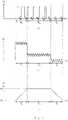
- exemplary graphs of the progression over time of: a) a driving voltage applied to the solenoid coil of a magnetic valve as a PWM signal together with an interleaved measuring voltage, b) a driving voltage applied to the solenoid coil as a PAM signal together with a superimposed measuring voltage, and c) the position of a plunger of a magnetic valve resulting from applying the drive voltage to the solenoid coil.
Fig. 1 depicts a dispenser/pipetting apparatus according to the present invention. A positive and anegative pressure source 1+, 1- selectable by a pressure switching means 2 apply a pressure to asystem fluid 9. Instead of employing a separate positive and anegative pressure source 1+, 1- a single pressure source with an adjustable pressure, such as a (plunger) pump, may be used. Thesystem fluid 9 is in fluid communication with a liquid 8 to be dispensed or aspirated via a pipetting/dispenser tip 6, which is typically attached to apipetting tube 5. In case thesystem fluid 9 is not a gas, such as air, theliquid 8 is separated from thesystem fluid 9 by air 10 (or another gas) in order to avoid contact (and therewith e.g. contamination of the liquid 8) with thesystem fluid 9. In the case of a dispenser theliquid 8 to be dispensed can itself be used as the system fluid 9 (and theinterjacent air 10 is not necessary). Amagnetic valve 3 is located in the path of thesystem fluid 9 in order to regulate its flow. Furthermore, arestriction 4, such as a capillary, may be located between themagnetic valve 3 and thetip 6. However, therestriction 4 may also be arranged between thepressure source 1+, 1- and themagnetic valve 3, or may even form part of themagnetic valve 3, e.g. it may be integrated into themagnetic valve 3. The purpose of therestrictor 4 is to restrict the flow of thesystem fluid 9 by exerting a certain desired flow resistance, whereby the flow resistance is typically chosen to be at least double that of theexterior opening 7 of thetip 6.- In
case liquid 8 is to be dispensed, a higher pressure than the pressure currently being exerted on the liquid 8 (e.g. above atmospheric pressure) is applied to thesystem fluid 9, i.e. thepositive pressure source 1+ is selected by the pressure switching means 2. The pressure switching means 2 may comprise two valves, one at the output of thepositive pressure source 1+, which is open when dispensing, and one at the output of the negative pressure source 1-, which is closed when dispensing. This higher pressure becomes effective on theliquid 8 to be dispensed from thetip 6 as soon as themagnetic valve 3 is opened and stays effective until themagnetic valve 3 is closed again. The amount (i.e. the volume) ofliquid 8 which is dispensed is dependent on the level of the pressure being applied and the length of time during which the pressure is applied, i.e. the time during which themagnetic valve 3 is open. If themagnetic valve 3 opens and closes essentially instantaneously (i.e. the opening and closing time are negligible), the holding time Th during which themagnetic valve 3 is held open determines the volume ofliquid 8 which is dispensed if the pressure is maintained at a constant level. Therefore, given the amount ofliquid 8 to be dispensed thecontrol unit 12 determines the necessary holding time Th for dispensing the desired volume ofliquid 8, and controls themagnetic valve 3 accordingly, as will be described in more detail below. - In
case liquid 8 is to be aspirated, a lower pressure than the pressure currently being exerted on the liquid 8 (e.g. below atmospheric pressure) is applied to thesystem fluid 9, i.e. the negative pressure source 1- is selected by the pressure switching means 2, e.g. the valve at the output of the negative pressure source 1- is opened and the one at the output of thepositive pressure source 1+ is closed. Again, this lower pressure becomes effective on theliquid 8 to be aspirated into thetip 6 as soon as themagnetic valve 3 is opened and stays effective until themagnetic valve 3 is closed again. - As previously indicated the amount/volume of
liquid 8 dispensed/aspirated varies based on manufacturing tolerances, aging and mechanical wear of the magnetic valve as well as environmental influences such as temperature and humidity, operating conditions such as pressure, liquid properties and supply voltage. All these influences can lead to changes of the switching behaviour of themagnetic valve 3, e.g. the opening and closing times are increased, and therefore are no longer negligible (or at least take on other values than the initial ones over time). Furthermore, the flow of thesystem fluid 9 decreases over time, for instance when themagnetic valve 3 is hindered from fully opening, e.g. due to clogging. This will reduce the amount/volume ofliquid 8 that is dispensed/aspirated during a fixed holding time Th determined by thecontrol unit 12 and used to control themagnetic valve 3. Consequently, the holding time Th should be adjusted (or calibrated) based on an appropriate feedback signal, as will be explained in the following. Fig. 2 schematically shows amagnetic valve 3 comprising asolenoid coil 13 and a mobile anchor forming aplunger 14. In order to open themagnetic valve 3 an opening current is applied as a driving current to thesolenoid coil 13, which drives theplunger 14 from its closed position Pc (shown inFig. 2 b) ) to an open position Po (shown inFig. 2 a) ). As soon as themagnetic valve 3 isopen system fluid 9 may flow through thepassage 16 of themagnetic valve 3, thereby transferring the pressure from the positive ornegative pressure source 1+, 1- to theliquid 8 to be dispensed or aspirated.- Typically, a
closing spring 15 is arranged at the mobile anchor to apply a closing force that pushes theplunger 14 back towards the closed position Pc. Therefore, once themagnetic valve 3 has been opened a holding current needs to be applied as a driving current to thesolenoid coil 13 to counteract the closing force of theclosing spring 15. This holding current is maintained during the holding time Th determined by thecontrol unit 12 such that the desired amount/volume ofliquid 8 is dispensed/aspirated. Once the holding time Th has passed themagnetic valve 3 is closed again. This can simply be achieved by no longer driving thesolenoid coil 13 and letting theclosing spring 15 close themagnetic valve 3, or alternatively when no closingspring 15 is employed applying a closing current having the opposite polarity to the opening and holding current as a driving current to thesolenoid coil 13 such that theplunger 14 is moved to the closed position Pc again. A closing current can also be employed together with theclosing spring 15, for example to decelerate (i.e. apply a breaking action on) theplunger 14 before reaching the closed position Pc in order to avoid strong impacts and thus increase the working lifespan of themagnetic valve 3. - In an open loop control system the driving currents are preset to certain levels for opening, holding open and closing the
magnetic valve 3. Likewise, the holding time Th is preselected depending on the desired amount ofliquid 8 to be dispensed (e.g. based on a lookup table). - To allow closed loop control of the magnetic valve 3 a feedback signal must be available. This is made possible by the present invention by measuring a capacitance at/of the
magnetic valve 3. The measured capacitance changes depending on the position P of theplunger 14 as indicated by the large capacitor illustrated inFig. 2 a) when themagnetic valve 3 is open and the mobile anchor is largely retracted within the solenoid coil 13 (plunger 14 in the open position Po) and the smaller capacitor illustrated inFig. 2 b) when themagnetic valve 3 is closed and the mobile anchor is less retracted within the solenoid coil 13 (plunger 14 in the closed position Pc). When themagnetic valve 3 for instance comprises a stationary anchor that is coaxially arranged adjacent to the mobile anchor and electrically connected to ametallic housing 17 of themagnetic valve 3, thesolenoid coil 13 and thehousing 17 can be connected to acapacitance measurement unit 11 for measuring the capacitance. Measuring the capacitance is achieved by applying a measuring voltage to thesolenoid coil 13 in addition to the driving current, e.g. by superimposing the measuring signal onto the driving signal. Thereby, the measuring signal may be an alternating current signal, a pseudo random noise signal or an exponential function shaped signal. Furthermore, the measuring signal and the driving signal may have different frequencies so that they can be easily separated from one another, e.g. by means of a highpass filter. - To achieve closed loop control of the
magnetic valve 3 the applied driving current can be adjusted dependent on the position P of the plunger determined based on the measured capacitance. This allows to achieve targeted opening, holding and closing times To, Th, Tc despite manufacturing tolerances, aging and mechanical wear of the magnetic valve as well as environmental influences such as temperature and humidity, operating conditions such as pressure, liquid properties and supply voltage. Fig. 3 displays graphs of two different examples for driving themagnetic valve 3.Fig. 3 a) shows a driving voltage ud applied as a pulse width modulated (PWM) signal having a duty cycle consisting of an active phase (ud > 0 VDC) and a passive phase (ud = 0 VDC). In this example the measuring voltage in the form of a sinusoidal signal is only present during the passive phase of the duty cycle of the PWM signal, i.e. the driving and measuring signals are interleaved. In the alternative example shown inFig. 3 b) the driving voltage ud is applied as a pulse amplitude modulated (PAM) signal. In this example the measuring voltage in the form of a sinusoidal signal is superimposed on the PAM driving signal and continuously present. The graph depicted in Fig. 3 c) shows the position P of theplunger 14 over time dependent on the driving voltage ud. During the opening time To the opening voltage is applied to the solenoid coil 13 (e.g. for two duty cycles of the PWM signal inFig. 3 a) ) to drive theplunger 14 from the closed position Pc to the open position Po. Subsequently, theplunger 14 is held in the open position Po by applying the holding voltage to thesolenoid coil 13 during the holding time Th (e.g. for four duty cycles of the PWM signal inFig. 3 a) ). Finally, theplunger 14 is forced back to the closed position Pc, in this case by setting the closing voltage to 0 V during the closing time Tc (e.g. for two duty cycles of the PWM signal inFig. 3 a) ) and leaving it to the closing force of theclosing spring 15 to retract theplunger 14. The desired amount ofliquid 8 to be dispensed or aspirated can then be precisely controlled by thecontrol unit 12 by appropriately adjusting the driving voltage ud dependent on the position of theplunger 14 determined based on the capacitance measured at themagnetic valve 3.- 1+
- positive pressure source
- 1-
- negative pressure source
- 2
- pressure switching means
- 3
- magnetic valve
- 4
- restriction, e.g. capillary
- 5
- pipetting tube
- 6
- dispenser/pipetting tip
- 7
- tip opening
- 8
- liquid
- 9
- system fluid
- 10
- air
- 11
- capacitance measurement unit
- 12
- control unit
- 13
- solenoid coil
- 14
- plunger (mobile anchor)
- 15
- closing spring
- 16
- passage
- 17
- housing
- P
- position of the plunger
- Pc
- closed position of the plunger
- Po
- open position of the plunger
- t
- time
- Tc
- closing time
- Th
- holding time
- To
- opening time
- ud
- driving voltage
Claims (20)
- A method for controlling a magnetic valve (3), comprising a solenoid coil (13) and a mobile anchor forming a plunger (14), wherein the plunger (14) is moveable between a closed position (Pc) and an open position (Po), the method comprising the steps of:- applying an opening current as a driving current to the solenoid coil (13) to drive the plunger (14) from the closed position (Pc) to the open position (Po);- measuring a capacitance at the magnetic valve (3);- determining a position (P) of the plunger (14) based on the measured capacitance,characterised in that the step of measuring the capacitance comprises the step of:- applying a measuring voltage to the solenoid coil (13).
- The method of claim 1, further comprising the step of:- holding the plunger (14) at a predetermined position (P), in particular at the open position (Po), for a predetermined holding time (Th) by applying a holding current as the driving current to the solenoid coil (13), the holding current in particular having a smaller amplitude than the opening current.
- The method of claim 1 or 2, further comprising the step of:- applying a closing current as the driving current to the solenoid coil (13) to drive the plunger (14) from the open position (Po) to the closed position (Pc), the closing current in particular having an opposite polarity to the opening current.
- The method of one of claims 1 to 3, wherein the magnetic valve (3) further comprises a stationary anchor, in particular coaxially arranged adjacent to the mobile anchor, electrically connected to a metallic housing (17) of the magnetic valve (3), wherein the solenoid coil (13) and the housing (17) are connected to a capacitance measurement unit (11) for measuring the capacitance.
- The method of one of claims 1 to 4, wherein the measuring voltage is applied as an alternating current signal, a pseudo random noise signal or an exponential function shaped signal.
- The method of claim 1 to 5, wherein the measuring voltage has a different frequency, in particular a higher frequency, than the driving current, the frequency of the measuring voltage in particular being higher than 1 kHz, more particularly higher than 10 kHz, even more particularly between 100 kHz and 1 MHz.
- The method of claim 6, wherein the measuring voltage has a different amplitude, in particular a lower amplitude, than a driving voltage associated with the driving current.
- The method of one of claims 5 to 7, wherein the measuring voltage is superimposed on the driving voltage associated with the driving current.
- The method of one of claims 1 to 8, wherein the driving current is applied as a pulse width modulated signal having a duty cycle consisting of an active phase and a passive phase, wherein the driving current is zero during the passive phase.
- The method of claim 9 and claim 5, wherein the measuring voltage is only present during the passive phase of the duty cycle of the pulse width modulated signal.
- The method of one of claims 1 to 10, further comprising the step of:- adjusting the driving current, in particular at least one of the opening current, the holding current and the closing current, in particular the amplitude, more particularly a pulse width of the pulse width modulated signal, in dependence of the position (P) of the plunger (14) .
- The method of one of claims 1 to 10, further comprising at least one of the following steps:- determining an opening time (To) of the magnetic valve (3) as a time interval between the plunger (14) leaving the closed position (Pc) and reaching the open position (Po) ;- determining a closing time (Tc) of the magnetic valve (3) as a time interval between the plunger (14) leaving the open position (Po) and reaching the closed position (Pc),and further comprising at least one of the following steps:- adjusting the driving current, in particular at least one of the opening current, the holding current and the closing current, in particular the amplitude, more particularly a pulse width of the pulse width modulated signal, in dependence of the opening time (To) and/or the closing time (Tc);- providing a fault indication in dependence of the opening time (To) and/or the closing time (Tc), in particular when the opening time (To) exceeds a first predefined value and/or when the closing time (Tc) exceeds a second predefined value.
- Use of the method according to claim 12 to adjust or calibrate a holding time (Th) of the magnetic valve (3) in dependence of the determined opening time (To) and/or closing time (Tc).
- Use of the method according to one of claims 1 to 10 to monitor operation of the magnetic valve (3) based on the position (P) of the plunger (14).
- A method for dispensing or aspirating a volume of liquid (8) comprising the steps of:- applying a pressure from a pressure source (1+, 1-) to a system fluid (9);- controlling a flow of the system fluid (9) by means of a magnetic valve (3) located between the pressure source (1+, 1-) and a dispenser or pipetting tip (6);- dispensing or aspirating the volume of liquid (8) through an exterior opening (7) of the tip (6) dependent on the flow of the system fluid (9), the system fluid (9) being in fluid communication with the liquid (8) to be dispensed or aspirated,wherein controlling the flow comprises:- determining a flow time in dependence of the volume of liquid (8) to be dispensed or aspirated;- controlling the magnetic valve (3) according to the method of claim 2, in particular in combination with the method of one of claims 3 to 11, wherein the predetermined holding time (Th) is set to the flow time.
- The method of claim 15, wherein a restrictor (4), such as a capillary, for restricting the flow is interconnected between the pressure source (1+, 1-) and the tip (6), the restrictor (4) in particular having a flow resistance which is at least twice that of the exterior opening (7) of the tip (6).
- A dispenser/pipetting apparatus comprising:- a pressure source (1+, 1-) adapted to apply a pressure to a system fluid (9), the system fluid (9) being in fluid communication with a liquid (8) to be dispensed or aspirated;- a magnetic valve (3), comprising a solenoid coil (13) and a mobile anchor forming a plunger (14), wherein the plunger (14) is moveable between a closed position (Pc) and an open position (Pc);- a dispenser or pipetting tip (6) with an exterior opening (7) through which the liquid (8) can be dispensed or aspirated;- a capacitance measurement unit (11) adapted to measure a capacitance at the magnetic valve (3); and- a control unit (12) adapted to control a flow of the system fluid (9) by means of the magnetic valve (3), which is located between the pressure source (1+, 1-) and the tip (6),wherein the control unit (12) is adapted to:- determine a flow time in dependence of a volume of liquid (8) to be dispensed or aspirated; and- control the magnetic valve (3) according to the method of claim 2, in particular in combination with the method of one of claims 3 to 11, wherein the predetermined holding time (Th) is set to the flow time.
- The apparatus according to claim 17, wherein the magnetic valve (3) further comprises a stationary anchor, in particular coaxially arranged adjacent to the mobile anchor, electrically connected to a metallic housing (17) of the magnetic valve (3), wherein the solenoid coil (13) and the housing (17) are connected to the capacitance measurement unit (11) for measuring the capacitance.
- The apparatus of claim 17 or 18, further comprising a restrictor (4), such as a capillary, adapted to restrict the flow and interconnected between the pressure source (1+, 1-) and the tip (6), the restrictor (4) in particular having a flow resistance which is at least twice that of the exterior opening (7) of the tip (6).
- An automated liquid handling system comprising the apparatus of one of claims 17 to 19.
Priority Applications (4)
| Application Number | Priority Date | Filing Date | Title |
|---|---|---|---|
| EP18197661.4AEP3628902B1 (en) | 2018-09-28 | 2018-09-28 | Method for controlling a magnetic valve and method for dispensing or aspirating a volume of liquid as well as corresponding dispenser/pipetting apparatus |
| US17/276,731US11719355B2 (en) | 2018-09-28 | 2019-09-20 | Method for controlling a magnetic valve and method for dispensing or aspirating a volume of liquid as well as corresponding dispenser/pipetting apparatus |
| PCT/EP2019/075364WO2020064559A1 (en) | 2018-09-28 | 2019-09-20 | A method for dispensing or aspirating a volume of liquid using a magnetic valve and as well as a corresponding dispenser/pipetting apparatus |
| CN201980063561.7ACN112789436B (en) | 2018-09-28 | 2019-09-20 | Method for controlling solenoid valve and method for dispensing or aspirating liquid volume and corresponding dispenser/pipetting device |
Applications Claiming Priority (1)
| Application Number | Priority Date | Filing Date | Title |
|---|---|---|---|
| EP18197661.4AEP3628902B1 (en) | 2018-09-28 | 2018-09-28 | Method for controlling a magnetic valve and method for dispensing or aspirating a volume of liquid as well as corresponding dispenser/pipetting apparatus |
Publications (2)
| Publication Number | Publication Date |
|---|---|
| EP3628902A1 EP3628902A1 (en) | 2020-04-01 |
| EP3628902B1true EP3628902B1 (en) | 2022-06-22 |
Family
ID=63713694
Family Applications (1)
| Application Number | Title | Priority Date | Filing Date |
|---|---|---|---|
| EP18197661.4AActiveEP3628902B1 (en) | 2018-09-28 | 2018-09-28 | Method for controlling a magnetic valve and method for dispensing or aspirating a volume of liquid as well as corresponding dispenser/pipetting apparatus |
Country Status (4)
| Country | Link |
|---|---|
| US (1) | US11719355B2 (en) |
| EP (1) | EP3628902B1 (en) |
| CN (1) | CN112789436B (en) |
| WO (1) | WO2020064559A1 (en) |
Families Citing this family (4)
| Publication number | Priority date | Publication date | Assignee | Title |
|---|---|---|---|---|
| DE102018217661A1 (en)* | 2018-10-15 | 2020-04-16 | Continental Teves Ag & Co. Ohg | Method for determining a switching state of a valve and electromagnetic valve arrangement |
| DE102021101335A1 (en)* | 2021-01-22 | 2022-07-28 | Amazonen-Werke H. Dreyer SE & Co. KG | Method for controlling a solenoid valve used for flow rate control in an agricultural spreading machine |
| DE102022202189A1 (en)* | 2022-03-03 | 2023-09-07 | Robert Bosch Gesellschaft mit beschränkter Haftung | Method for determining a lower current threshold value of a current band of a magnet coil of a magnet valve for a valve unit, device and vehicle that communicates fluidly with a pressurized fluid reservoir |
| CN114733588A (en)* | 2022-05-12 | 2022-07-12 | 杭州天微基因科技有限公司 | Micro-fluidic power chip based on magnetic control technology |
Family Cites Families (25)
| Publication number | Priority date | Publication date | Assignee | Title |
|---|---|---|---|---|
| US1538906A (en)* | 1920-10-25 | 1925-05-26 | Wigginton Company | Potential indicator |
| US4122378A (en)* | 1976-12-16 | 1978-10-24 | Facet Enterprises, Inc. | Solid state switching circuit for an electromagnetic pump |
| US5244179A (en)* | 1992-08-21 | 1993-09-14 | Sloan Valve Company | Diaphragm stop for sensor-operated, battery-powered flush valve |
| JPH07189787A (en)* | 1993-12-28 | 1995-07-28 | Honda Motor Co Ltd | Fuel injection valve drive controller |
| CN2211530Y (en)* | 1995-02-25 | 1995-11-01 | 王红柱 | Automatic valve actuator |
| US5741554A (en)* | 1996-07-26 | 1998-04-21 | Bio Dot, Inc. | Method of dispensing a liquid reagent |
| JPH11148439A (en)* | 1997-06-26 | 1999-06-02 | Hitachi Ltd | Electromagnetic fuel injection valve and fuel injection method thereof |
| US20030207464A1 (en) | 1999-02-19 | 2003-11-06 | Tony Lemmo | Methods for microfluidic aspirating and dispensing |
| DE19913870A1 (en)* | 1999-03-26 | 2000-10-19 | Siemens Ag | Positioning sensor used for operating electromagnetic control of valves has a capacitor coupled to a lifting movement |
| SE9901511D0 (en)* | 1999-04-27 | 1999-04-27 | Siemens Elema Ab | Check valve for anesthetic device |
| US6405693B2 (en)* | 2000-02-28 | 2002-06-18 | Toyota Jidosha Kabushiki Kaisha | Internal combustion engine and method for controlling valve of internal combustion engine |
| US20070241298A1 (en)* | 2000-02-29 | 2007-10-18 | Kay Herbert | Electromagnetic apparatus and method for controlling fluid flow |
| EP1343180B1 (en)* | 2000-11-14 | 2011-07-20 | Yuken Kogyo Kabushiki Kaisha | Electromagnetic operating device |
| DE10140157B4 (en)* | 2001-08-16 | 2010-07-22 | Robert Bosch Gmbh | Method and device for driving a solenoid valve |
| KR100608686B1 (en)* | 2004-08-25 | 2006-08-08 | 엘지전자 주식회사 | Variable displacement reciprocating compressor and its control method |
| SE0501531L (en)* | 2005-07-01 | 2007-01-02 | Haldex Traction Ab | Method, device and system |
| CN1955529A (en)* | 2005-10-26 | 2007-05-02 | 浙江三花制冷集团有限公司 | Control loop of electromagnet valve and its control method |
| US8376313B2 (en)* | 2007-03-28 | 2013-02-19 | Masco Corporation Of Indiana | Capacitive touch sensor |
| JP4359855B2 (en)* | 2007-07-09 | 2009-11-11 | Smc株式会社 | Solenoid valve drive circuit and solenoid valve |
| US8130482B2 (en)* | 2008-04-21 | 2012-03-06 | Tai-Her Yang | Electromagnetic actuating device being actuated by AC power and held by DC power |
| CN102410396B (en)* | 2011-08-05 | 2014-04-09 | 安徽中科光电色选机械有限公司 | High-frequency electromagnetic valve and driving circuit thereof |
| US9534795B2 (en)* | 2012-10-05 | 2017-01-03 | Schneider Electric Buildings, Llc | Advanced valve actuator with remote location flow reset |
| CN103343741B (en)* | 2013-07-10 | 2015-11-25 | 中联重科股份有限公司 | Hydraulic oil replacement control method for double-cylinder pumping device, double-cylinder pumping device and equipment |
| WO2018091075A1 (en) | 2016-11-15 | 2018-05-24 | Tecan Schweiz Ag | Pipetting method and pipetting device |
| CN107781345B (en)* | 2017-12-05 | 2023-12-12 | 华东交通大学 | Magnetorheological damper capable of detecting piston displacement |
- 2018
- 2018-09-28EPEP18197661.4Apatent/EP3628902B1/enactiveActive
- 2019
- 2019-09-20WOPCT/EP2019/075364patent/WO2020064559A1/ennot_activeCeased
- 2019-09-20USUS17/276,731patent/US11719355B2/enactiveActive
- 2019-09-20CNCN201980063561.7Apatent/CN112789436B/enactiveActive
Also Published As
| Publication number | Publication date |
|---|---|
| CN112789436A (en) | 2021-05-11 |
| US11719355B2 (en) | 2023-08-08 |
| US20220034420A1 (en) | 2022-02-03 |
| CN112789436B (en) | 2024-07-09 |
| WO2020064559A1 (en) | 2020-04-02 |
| EP3628902A1 (en) | 2020-04-01 |
Similar Documents
| Publication | Publication Date | Title |
|---|---|---|
| US11719355B2 (en) | Method for controlling a magnetic valve and method for dispensing or aspirating a volume of liquid as well as corresponding dispenser/pipetting apparatus | |
| US6669909B2 (en) | Liquid droplet dispensing | |
| US20200209274A1 (en) | Pipetting device with functional checking and method for functional checking of a pipetting device | |
| US10466264B2 (en) | Dispensing assembly | |
| US11602745B2 (en) | Integrated pipetting apparatus | |
| US20140010667A1 (en) | Device and method for uptake or release of a liquid | |
| US6200100B1 (en) | Method and system for preventing incontinent liquid drip | |
| JP7145973B2 (en) | Intelligent pressure controller and method for maintaining manifold pressure in diagnostic test equipment | |
| CN111465836B (en) | Pipetting device, liquid treatment system and method for controlling pipetting | |
| EP2236873B1 (en) | Adjustment spring device for a pinch solenoid valve | |
| US12060951B2 (en) | Adjustment device for a vacuum area with pressure measuring functionality | |
| JPH01249162A (en) | Resist liquid discharge device | |
| US20250138041A1 (en) | Apparatus for the automated pipeting and related process | |
| JP2004237155A (en) | Method for discharging constant amount of liquid and apparatus therefor | |
| Liu et al. | A self-adjusted precise liquid handling system | |
| HK40035127A (en) | Intelligent pressure control apparatus and methods for maintaining manifold pressure in a diagnostic testing apparatus |
Legal Events
| Date | Code | Title | Description |
|---|---|---|---|
| PUAI | Public reference made under article 153(3) epc to a published international application that has entered the european phase | Free format text:ORIGINAL CODE: 0009012 | |
| STAA | Information on the status of an ep patent application or granted ep patent | Free format text:STATUS: THE APPLICATION HAS BEEN PUBLISHED | |
| AK | Designated contracting states | Kind code of ref document:A1 Designated state(s):AL AT BE BG CH CY CZ DE DK EE ES FI FR GB GR HR HU IE IS IT LI LT LU LV MC MK MT NL NO PL PT RO RS SE SI SK SM TR | |
| AX | Request for extension of the european patent | Extension state:BA ME | |
| STAA | Information on the status of an ep patent application or granted ep patent | Free format text:STATUS: REQUEST FOR EXAMINATION WAS MADE | |
| 17P | Request for examination filed | Effective date:20201001 | |
| RBV | Designated contracting states (corrected) | Designated state(s):AL AT BE BG CH CY CZ DE DK EE ES FI FR GB GR HR HU IE IS IT LI LT LU LV MC MK MT NL NO PL PT RO RS SE SI SK SM TR | |
| REG | Reference to a national code | Ref country code:DE Ref legal event code:R079 Ref document number:602018036948 Country of ref document:DE Free format text:PREVIOUS MAIN CLASS: F16K0031060000 Ipc:B01L0003020000 | |
| GRAP | Despatch of communication of intention to grant a patent | Free format text:ORIGINAL CODE: EPIDOSNIGR1 | |
| STAA | Information on the status of an ep patent application or granted ep patent | Free format text:STATUS: GRANT OF PATENT IS INTENDED | |
| RIC1 | Information provided on ipc code assigned before grant | Ipc:G01F 13/00 20060101ALI20220119BHEP Ipc:G01F 11/02 20060101ALI20220119BHEP Ipc:F16K 31/06 20060101ALI20220119BHEP Ipc:H01F 7/18 20060101ALI20220119BHEP Ipc:B01L 3/02 20060101AFI20220119BHEP | |
| INTG | Intention to grant announced | Effective date:20220209 | |
| GRAS | Grant fee paid | Free format text:ORIGINAL CODE: EPIDOSNIGR3 | |
| GRAA | (expected) grant | Free format text:ORIGINAL CODE: 0009210 | |
| STAA | Information on the status of an ep patent application or granted ep patent | Free format text:STATUS: THE PATENT HAS BEEN GRANTED | |
| AK | Designated contracting states | Kind code of ref document:B1 Designated state(s):AL AT BE BG CH CY CZ DE DK EE ES FI FR GB GR HR HU IE IS IT LI LT LU LV MC MK MT NL NO PL PT RO RS SE SI SK SM TR | |
| REG | Reference to a national code | Ref country code:GB Ref legal event code:FG4D | |
| REG | Reference to a national code | Ref country code:CH Ref legal event code:EP | |
| REG | Reference to a national code | Ref country code:DE Ref legal event code:R096 Ref document number:602018036948 Country of ref document:DE | |
| REG | Reference to a national code | Ref country code:AT Ref legal event code:REF Ref document number:1499418 Country of ref document:AT Kind code of ref document:T Effective date:20220715 | |
| REG | Reference to a national code | Ref country code:IE Ref legal event code:FG4D | |
| REG | Reference to a national code | Ref country code:LT Ref legal event code:MG9D | |
| REG | Reference to a national code | Ref country code:NL Ref legal event code:MP Effective date:20220622 | |
| PG25 | Lapsed in a contracting state [announced via postgrant information from national office to epo] | Ref country code:SE Free format text:LAPSE BECAUSE OF FAILURE TO SUBMIT A TRANSLATION OF THE DESCRIPTION OR TO PAY THE FEE WITHIN THE PRESCRIBED TIME-LIMIT Effective date:20220622 Ref country code:NO Free format text:LAPSE BECAUSE OF FAILURE TO SUBMIT A TRANSLATION OF THE DESCRIPTION OR TO PAY THE FEE WITHIN THE PRESCRIBED TIME-LIMIT Effective date:20220922 Ref country code:LT Free format text:LAPSE BECAUSE OF FAILURE TO SUBMIT A TRANSLATION OF THE DESCRIPTION OR TO PAY THE FEE WITHIN THE PRESCRIBED TIME-LIMIT Effective date:20220622 Ref country code:HR Free format text:LAPSE BECAUSE OF FAILURE TO SUBMIT A TRANSLATION OF THE DESCRIPTION OR TO PAY THE FEE WITHIN THE PRESCRIBED TIME-LIMIT Effective date:20220622 Ref country code:GR Free format text:LAPSE BECAUSE OF FAILURE TO SUBMIT A TRANSLATION OF THE DESCRIPTION OR TO PAY THE FEE WITHIN THE PRESCRIBED TIME-LIMIT Effective date:20220923 Ref country code:FI Free format text:LAPSE BECAUSE OF FAILURE TO SUBMIT A TRANSLATION OF THE DESCRIPTION OR TO PAY THE FEE WITHIN THE PRESCRIBED TIME-LIMIT Effective date:20220622 Ref country code:BG Free format text:LAPSE BECAUSE OF FAILURE TO SUBMIT A TRANSLATION OF THE DESCRIPTION OR TO PAY THE FEE WITHIN THE PRESCRIBED TIME-LIMIT Effective date:20220922 | |
| REG | Reference to a national code | Ref country code:AT Ref legal event code:MK05 Ref document number:1499418 Country of ref document:AT Kind code of ref document:T Effective date:20220622 | |
| PG25 | Lapsed in a contracting state [announced via postgrant information from national office to epo] | Ref country code:RS Free format text:LAPSE BECAUSE OF FAILURE TO SUBMIT A TRANSLATION OF THE DESCRIPTION OR TO PAY THE FEE WITHIN THE PRESCRIBED TIME-LIMIT Effective date:20220622 Ref country code:LV Free format text:LAPSE BECAUSE OF FAILURE TO SUBMIT A TRANSLATION OF THE DESCRIPTION OR TO PAY THE FEE WITHIN THE PRESCRIBED TIME-LIMIT Effective date:20220622 | |
| PG25 | Lapsed in a contracting state [announced via postgrant information from national office to epo] | Ref country code:NL Free format text:LAPSE BECAUSE OF FAILURE TO SUBMIT A TRANSLATION OF THE DESCRIPTION OR TO PAY THE FEE WITHIN THE PRESCRIBED TIME-LIMIT Effective date:20220622 | |
| PG25 | Lapsed in a contracting state [announced via postgrant information from national office to epo] | Ref country code:SM Free format text:LAPSE BECAUSE OF FAILURE TO SUBMIT A TRANSLATION OF THE DESCRIPTION OR TO PAY THE FEE WITHIN THE PRESCRIBED TIME-LIMIT Effective date:20220622 Ref country code:SK Free format text:LAPSE BECAUSE OF FAILURE TO SUBMIT A TRANSLATION OF THE DESCRIPTION OR TO PAY THE FEE WITHIN THE PRESCRIBED TIME-LIMIT Effective date:20220622 Ref country code:RO Free format text:LAPSE BECAUSE OF FAILURE TO SUBMIT A TRANSLATION OF THE DESCRIPTION OR TO PAY THE FEE WITHIN THE PRESCRIBED TIME-LIMIT Effective date:20220622 Ref country code:PT Free format text:LAPSE BECAUSE OF FAILURE TO SUBMIT A TRANSLATION OF THE DESCRIPTION OR TO PAY THE FEE WITHIN THE PRESCRIBED TIME-LIMIT Effective date:20221024 Ref country code:ES Free format text:LAPSE BECAUSE OF FAILURE TO SUBMIT A TRANSLATION OF THE DESCRIPTION OR TO PAY THE FEE WITHIN THE PRESCRIBED TIME-LIMIT Effective date:20220622 Ref country code:EE Free format text:LAPSE BECAUSE OF FAILURE TO SUBMIT A TRANSLATION OF THE DESCRIPTION OR TO PAY THE FEE WITHIN THE PRESCRIBED TIME-LIMIT Effective date:20220622 Ref country code:CZ Free format text:LAPSE BECAUSE OF FAILURE TO SUBMIT A TRANSLATION OF THE DESCRIPTION OR TO PAY THE FEE WITHIN THE PRESCRIBED TIME-LIMIT Effective date:20220622 Ref country code:AT Free format text:LAPSE BECAUSE OF FAILURE TO SUBMIT A TRANSLATION OF THE DESCRIPTION OR TO PAY THE FEE WITHIN THE PRESCRIBED TIME-LIMIT Effective date:20220622 | |
| PG25 | Lapsed in a contracting state [announced via postgrant information from national office to epo] | Ref country code:PL Free format text:LAPSE BECAUSE OF FAILURE TO SUBMIT A TRANSLATION OF THE DESCRIPTION OR TO PAY THE FEE WITHIN THE PRESCRIBED TIME-LIMIT Effective date:20220622 Ref country code:IS Free format text:LAPSE BECAUSE OF FAILURE TO SUBMIT A TRANSLATION OF THE DESCRIPTION OR TO PAY THE FEE WITHIN THE PRESCRIBED TIME-LIMIT Effective date:20221022 | |
| REG | Reference to a national code | Ref country code:DE Ref legal event code:R097 Ref document number:602018036948 Country of ref document:DE | |
| PG25 | Lapsed in a contracting state [announced via postgrant information from national office to epo] | Ref country code:AL Free format text:LAPSE BECAUSE OF FAILURE TO SUBMIT A TRANSLATION OF THE DESCRIPTION OR TO PAY THE FEE WITHIN THE PRESCRIBED TIME-LIMIT Effective date:20220622 | |
| PG25 | Lapsed in a contracting state [announced via postgrant information from national office to epo] | Ref country code:MC Free format text:LAPSE BECAUSE OF FAILURE TO SUBMIT A TRANSLATION OF THE DESCRIPTION OR TO PAY THE FEE WITHIN THE PRESCRIBED TIME-LIMIT Effective date:20220622 Ref country code:DK Free format text:LAPSE BECAUSE OF FAILURE TO SUBMIT A TRANSLATION OF THE DESCRIPTION OR TO PAY THE FEE WITHIN THE PRESCRIBED TIME-LIMIT Effective date:20220622 | |
| PLBE | No opposition filed within time limit | Free format text:ORIGINAL CODE: 0009261 | |
| STAA | Information on the status of an ep patent application or granted ep patent | Free format text:STATUS: NO OPPOSITION FILED WITHIN TIME LIMIT | |
| REG | Reference to a national code | Ref country code:BE Ref legal event code:MM Effective date:20220930 | |
| 26N | No opposition filed | Effective date:20230323 | |
| P01 | Opt-out of the competence of the unified patent court (upc) registered | Effective date:20230523 | |
| PG25 | Lapsed in a contracting state [announced via postgrant information from national office to epo] | Ref country code:LU Free format text:LAPSE BECAUSE OF NON-PAYMENT OF DUE FEES Effective date:20220928 | |
| PG25 | Lapsed in a contracting state [announced via postgrant information from national office to epo] | Ref country code:IE Free format text:LAPSE BECAUSE OF NON-PAYMENT OF DUE FEES Effective date:20220928 | |
| PG25 | Lapsed in a contracting state [announced via postgrant information from national office to epo] | Ref country code:SI Free format text:LAPSE BECAUSE OF FAILURE TO SUBMIT A TRANSLATION OF THE DESCRIPTION OR TO PAY THE FEE WITHIN THE PRESCRIBED TIME-LIMIT Effective date:20220622 | |
| PG25 | Lapsed in a contracting state [announced via postgrant information from national office to epo] | Ref country code:BE Free format text:LAPSE BECAUSE OF NON-PAYMENT OF DUE FEES Effective date:20220930 | |
| PG25 | Lapsed in a contracting state [announced via postgrant information from national office to epo] | Ref country code:IT Free format text:LAPSE BECAUSE OF FAILURE TO SUBMIT A TRANSLATION OF THE DESCRIPTION OR TO PAY THE FEE WITHIN THE PRESCRIBED TIME-LIMIT Effective date:20220622 | |
| PG25 | Lapsed in a contracting state [announced via postgrant information from national office to epo] | Ref country code:HU Free format text:LAPSE BECAUSE OF FAILURE TO SUBMIT A TRANSLATION OF THE DESCRIPTION OR TO PAY THE FEE WITHIN THE PRESCRIBED TIME-LIMIT; INVALID AB INITIO Effective date:20180928 | |
| PG25 | Lapsed in a contracting state [announced via postgrant information from national office to epo] | Ref country code:CY Free format text:LAPSE BECAUSE OF FAILURE TO SUBMIT A TRANSLATION OF THE DESCRIPTION OR TO PAY THE FEE WITHIN THE PRESCRIBED TIME-LIMIT Effective date:20220622 | |
| PG25 | Lapsed in a contracting state [announced via postgrant information from national office to epo] | Ref country code:MK Free format text:LAPSE BECAUSE OF FAILURE TO SUBMIT A TRANSLATION OF THE DESCRIPTION OR TO PAY THE FEE WITHIN THE PRESCRIBED TIME-LIMIT Effective date:20220622 | |
| PG25 | Lapsed in a contracting state [announced via postgrant information from national office to epo] | Ref country code:MT Free format text:LAPSE BECAUSE OF FAILURE TO SUBMIT A TRANSLATION OF THE DESCRIPTION OR TO PAY THE FEE WITHIN THE PRESCRIBED TIME-LIMIT Effective date:20220622 | |
| PGFP | Annual fee paid to national office [announced via postgrant information from national office to epo] | Ref country code:DE Payment date:20240806 Year of fee payment:7 | |
| PGFP | Annual fee paid to national office [announced via postgrant information from national office to epo] | Ref country code:GB Payment date:20240808 Year of fee payment:7 | |
| PGFP | Annual fee paid to national office [announced via postgrant information from national office to epo] | Ref country code:FR Payment date:20240808 Year of fee payment:7 | |
| PG25 | Lapsed in a contracting state [announced via postgrant information from national office to epo] | Ref country code:BG Free format text:LAPSE BECAUSE OF FAILURE TO SUBMIT A TRANSLATION OF THE DESCRIPTION OR TO PAY THE FEE WITHIN THE PRESCRIBED TIME-LIMIT Effective date:20220622 | |
| PG25 | Lapsed in a contracting state [announced via postgrant information from national office to epo] | Ref country code:BG Free format text:LAPSE BECAUSE OF FAILURE TO SUBMIT A TRANSLATION OF THE DESCRIPTION OR TO PAY THE FEE WITHIN THE PRESCRIBED TIME-LIMIT Effective date:20220622 | |
| PGFP | Annual fee paid to national office [announced via postgrant information from national office to epo] | Ref country code:CH Payment date:20241001 Year of fee payment:7 |