EP3628244A1 - Intervertebral implant with keel - Google Patents
Intervertebral implant with keelDownload PDFInfo
- Publication number
- EP3628244A1 EP3628244A1EP19186610.2AEP19186610AEP3628244A1EP 3628244 A1EP3628244 A1EP 3628244A1EP 19186610 AEP19186610 AEP 19186610AEP 3628244 A1EP3628244 A1EP 3628244A1
- Authority
- EP
- European Patent Office
- Prior art keywords
- implant
- keel
- component
- insertion direction
- pair
- Prior art date
- Legal status (The legal status is an assumption and is not a legal conclusion. Google has not performed a legal analysis and makes no representation as to the accuracy of the status listed.)
- Pending
Links
Images


Classifications
- A—HUMAN NECESSITIES
- A61—MEDICAL OR VETERINARY SCIENCE; HYGIENE
- A61F—FILTERS IMPLANTABLE INTO BLOOD VESSELS; PROSTHESES; DEVICES PROVIDING PATENCY TO, OR PREVENTING COLLAPSING OF, TUBULAR STRUCTURES OF THE BODY, e.g. STENTS; ORTHOPAEDIC, NURSING OR CONTRACEPTIVE DEVICES; FOMENTATION; TREATMENT OR PROTECTION OF EYES OR EARS; BANDAGES, DRESSINGS OR ABSORBENT PADS; FIRST-AID KITS
- A61F2/00—Filters implantable into blood vessels; Prostheses, i.e. artificial substitutes or replacements for parts of the body; Appliances for connecting them with the body; Devices providing patency to, or preventing collapsing of, tubular structures of the body, e.g. stents
- A61F2/02—Prostheses implantable into the body
- A61F2/30—Joints
- A61F2/44—Joints for the spine, e.g. vertebrae, spinal discs
- A61F2/442—Intervertebral or spinal discs, e.g. resilient
- A—HUMAN NECESSITIES
- A61—MEDICAL OR VETERINARY SCIENCE; HYGIENE
- A61B—DIAGNOSIS; SURGERY; IDENTIFICATION
- A61B17/00—Surgical instruments, devices or methods
- A61B17/14—Surgical saws
- A61B17/142—Surgical saws with reciprocating saw blades, e.g. with cutting edges at the distal end of the saw blades
- A61B17/144—Surgical saws with reciprocating saw blades, e.g. with cutting edges at the distal end of the saw blades with cutting edges at the side of the saw blades
- A—HUMAN NECESSITIES
- A61—MEDICAL OR VETERINARY SCIENCE; HYGIENE
- A61B—DIAGNOSIS; SURGERY; IDENTIFICATION
- A61B17/00—Surgical instruments, devices or methods
- A61B17/14—Surgical saws
- A61B17/15—Guides therefor
- A—HUMAN NECESSITIES
- A61—MEDICAL OR VETERINARY SCIENCE; HYGIENE
- A61B—DIAGNOSIS; SURGERY; IDENTIFICATION
- A61B17/00—Surgical instruments, devices or methods
- A61B17/16—Instruments for performing osteoclasis; Drills or chisels for bones; Trepans
- A61B17/1604—Chisels; Rongeurs; Punches; Stamps
- A—HUMAN NECESSITIES
- A61—MEDICAL OR VETERINARY SCIENCE; HYGIENE
- A61B—DIAGNOSIS; SURGERY; IDENTIFICATION
- A61B17/00—Surgical instruments, devices or methods
- A61B17/16—Instruments for performing osteoclasis; Drills or chisels for bones; Trepans
- A61B17/1662—Instruments for performing osteoclasis; Drills or chisels for bones; Trepans for particular parts of the body
- A61B17/1671—Instruments for performing osteoclasis; Drills or chisels for bones; Trepans for particular parts of the body for the spine
- A—HUMAN NECESSITIES
- A61—MEDICAL OR VETERINARY SCIENCE; HYGIENE
- A61F—FILTERS IMPLANTABLE INTO BLOOD VESSELS; PROSTHESES; DEVICES PROVIDING PATENCY TO, OR PREVENTING COLLAPSING OF, TUBULAR STRUCTURES OF THE BODY, e.g. STENTS; ORTHOPAEDIC, NURSING OR CONTRACEPTIVE DEVICES; FOMENTATION; TREATMENT OR PROTECTION OF EYES OR EARS; BANDAGES, DRESSINGS OR ABSORBENT PADS; FIRST-AID KITS
- A61F2/00—Filters implantable into blood vessels; Prostheses, i.e. artificial substitutes or replacements for parts of the body; Appliances for connecting them with the body; Devices providing patency to, or preventing collapsing of, tubular structures of the body, e.g. stents
- A61F2/02—Prostheses implantable into the body
- A61F2/30—Joints
- A61F2/44—Joints for the spine, e.g. vertebrae, spinal discs
- A61F2/442—Intervertebral or spinal discs, e.g. resilient
- A61F2/4425—Intervertebral or spinal discs, e.g. resilient made of articulated components
- A—HUMAN NECESSITIES
- A61—MEDICAL OR VETERINARY SCIENCE; HYGIENE
- A61F—FILTERS IMPLANTABLE INTO BLOOD VESSELS; PROSTHESES; DEVICES PROVIDING PATENCY TO, OR PREVENTING COLLAPSING OF, TUBULAR STRUCTURES OF THE BODY, e.g. STENTS; ORTHOPAEDIC, NURSING OR CONTRACEPTIVE DEVICES; FOMENTATION; TREATMENT OR PROTECTION OF EYES OR EARS; BANDAGES, DRESSINGS OR ABSORBENT PADS; FIRST-AID KITS
- A61F2/00—Filters implantable into blood vessels; Prostheses, i.e. artificial substitutes or replacements for parts of the body; Appliances for connecting them with the body; Devices providing patency to, or preventing collapsing of, tubular structures of the body, e.g. stents
- A61F2/02—Prostheses implantable into the body
- A61F2/30—Joints
- A61F2/46—Special tools for implanting artificial joints
- A61F2/4603—Special tools for implanting artificial joints for insertion or extraction of endoprosthetic joints or of accessories thereof
- A61F2/4611—Special tools for implanting artificial joints for insertion or extraction of endoprosthetic joints or of accessories thereof of spinal prostheses
- A—HUMAN NECESSITIES
- A61—MEDICAL OR VETERINARY SCIENCE; HYGIENE
- A61F—FILTERS IMPLANTABLE INTO BLOOD VESSELS; PROSTHESES; DEVICES PROVIDING PATENCY TO, OR PREVENTING COLLAPSING OF, TUBULAR STRUCTURES OF THE BODY, e.g. STENTS; ORTHOPAEDIC, NURSING OR CONTRACEPTIVE DEVICES; FOMENTATION; TREATMENT OR PROTECTION OF EYES OR EARS; BANDAGES, DRESSINGS OR ABSORBENT PADS; FIRST-AID KITS
- A61F2/00—Filters implantable into blood vessels; Prostheses, i.e. artificial substitutes or replacements for parts of the body; Appliances for connecting them with the body; Devices providing patency to, or preventing collapsing of, tubular structures of the body, e.g. stents
- A61F2/02—Prostheses implantable into the body
- A61F2/30—Joints
- A61F2/46—Special tools for implanting artificial joints
- A61F2/4684—Trial or dummy prostheses
- A—HUMAN NECESSITIES
- A61—MEDICAL OR VETERINARY SCIENCE; HYGIENE
- A61B—DIAGNOSIS; SURGERY; IDENTIFICATION
- A61B17/00—Surgical instruments, devices or methods
- A61B17/02—Surgical instruments, devices or methods for holding wounds open, e.g. retractors; Tractors
- A61B17/025—Joint distractors
- A61B2017/0256—Joint distractors for the spine
- A—HUMAN NECESSITIES
- A61—MEDICAL OR VETERINARY SCIENCE; HYGIENE
- A61F—FILTERS IMPLANTABLE INTO BLOOD VESSELS; PROSTHESES; DEVICES PROVIDING PATENCY TO, OR PREVENTING COLLAPSING OF, TUBULAR STRUCTURES OF THE BODY, e.g. STENTS; ORTHOPAEDIC, NURSING OR CONTRACEPTIVE DEVICES; FOMENTATION; TREATMENT OR PROTECTION OF EYES OR EARS; BANDAGES, DRESSINGS OR ABSORBENT PADS; FIRST-AID KITS
- A61F2/00—Filters implantable into blood vessels; Prostheses, i.e. artificial substitutes or replacements for parts of the body; Appliances for connecting them with the body; Devices providing patency to, or preventing collapsing of, tubular structures of the body, e.g. stents
- A61F2/02—Prostheses implantable into the body
- A61F2/30—Joints
- A61F2002/30001—Additional features of subject-matter classified in A61F2/28, A61F2/30 and subgroups thereof
- A61F2002/30003—Material related properties of the prosthesis or of a coating on the prosthesis
- A61F2002/30004—Material related properties of the prosthesis or of a coating on the prosthesis the prosthesis being made from materials having different values of a given property at different locations within the same prosthesis
- A61F2002/30056—Material related properties of the prosthesis or of a coating on the prosthesis the prosthesis being made from materials having different values of a given property at different locations within the same prosthesis differing in radiographic density
- A—HUMAN NECESSITIES
- A61—MEDICAL OR VETERINARY SCIENCE; HYGIENE
- A61F—FILTERS IMPLANTABLE INTO BLOOD VESSELS; PROSTHESES; DEVICES PROVIDING PATENCY TO, OR PREVENTING COLLAPSING OF, TUBULAR STRUCTURES OF THE BODY, e.g. STENTS; ORTHOPAEDIC, NURSING OR CONTRACEPTIVE DEVICES; FOMENTATION; TREATMENT OR PROTECTION OF EYES OR EARS; BANDAGES, DRESSINGS OR ABSORBENT PADS; FIRST-AID KITS
- A61F2/00—Filters implantable into blood vessels; Prostheses, i.e. artificial substitutes or replacements for parts of the body; Appliances for connecting them with the body; Devices providing patency to, or preventing collapsing of, tubular structures of the body, e.g. stents
- A61F2/02—Prostheses implantable into the body
- A61F2/30—Joints
- A61F2002/30001—Additional features of subject-matter classified in A61F2/28, A61F2/30 and subgroups thereof
- A61F2002/30108—Shapes
- A61F2002/3011—Cross-sections or two-dimensional shapes
- A61F2002/30112—Rounded shapes, e.g. with rounded corners
- A—HUMAN NECESSITIES
- A61—MEDICAL OR VETERINARY SCIENCE; HYGIENE
- A61F—FILTERS IMPLANTABLE INTO BLOOD VESSELS; PROSTHESES; DEVICES PROVIDING PATENCY TO, OR PREVENTING COLLAPSING OF, TUBULAR STRUCTURES OF THE BODY, e.g. STENTS; ORTHOPAEDIC, NURSING OR CONTRACEPTIVE DEVICES; FOMENTATION; TREATMENT OR PROTECTION OF EYES OR EARS; BANDAGES, DRESSINGS OR ABSORBENT PADS; FIRST-AID KITS
- A61F2/00—Filters implantable into blood vessels; Prostheses, i.e. artificial substitutes or replacements for parts of the body; Appliances for connecting them with the body; Devices providing patency to, or preventing collapsing of, tubular structures of the body, e.g. stents
- A61F2/02—Prostheses implantable into the body
- A61F2/30—Joints
- A61F2002/30001—Additional features of subject-matter classified in A61F2/28, A61F2/30 and subgroups thereof
- A61F2002/30316—The prosthesis having different structural features at different locations within the same prosthesis; Connections between prosthetic parts; Special structural features of bone or joint prostheses not otherwise provided for
- A61F2002/30329—Connections or couplings between prosthetic parts, e.g. between modular parts; Connecting elements
- A61F2002/30331—Connections or couplings between prosthetic parts, e.g. between modular parts; Connecting elements made by longitudinally pushing a protrusion into a complementarily-shaped recess, e.g. held by friction fit
- A—HUMAN NECESSITIES
- A61—MEDICAL OR VETERINARY SCIENCE; HYGIENE
- A61F—FILTERS IMPLANTABLE INTO BLOOD VESSELS; PROSTHESES; DEVICES PROVIDING PATENCY TO, OR PREVENTING COLLAPSING OF, TUBULAR STRUCTURES OF THE BODY, e.g. STENTS; ORTHOPAEDIC, NURSING OR CONTRACEPTIVE DEVICES; FOMENTATION; TREATMENT OR PROTECTION OF EYES OR EARS; BANDAGES, DRESSINGS OR ABSORBENT PADS; FIRST-AID KITS
- A61F2/00—Filters implantable into blood vessels; Prostheses, i.e. artificial substitutes or replacements for parts of the body; Appliances for connecting them with the body; Devices providing patency to, or preventing collapsing of, tubular structures of the body, e.g. stents
- A61F2/02—Prostheses implantable into the body
- A61F2/30—Joints
- A61F2002/30001—Additional features of subject-matter classified in A61F2/28, A61F2/30 and subgroups thereof
- A61F2002/30316—The prosthesis having different structural features at different locations within the same prosthesis; Connections between prosthetic parts; Special structural features of bone or joint prostheses not otherwise provided for
- A61F2002/30329—Connections or couplings between prosthetic parts, e.g. between modular parts; Connecting elements
- A61F2002/30383—Connections or couplings between prosthetic parts, e.g. between modular parts; Connecting elements made by laterally inserting a protrusion, e.g. a rib into a complementarily-shaped groove
- A—HUMAN NECESSITIES
- A61—MEDICAL OR VETERINARY SCIENCE; HYGIENE
- A61F—FILTERS IMPLANTABLE INTO BLOOD VESSELS; PROSTHESES; DEVICES PROVIDING PATENCY TO, OR PREVENTING COLLAPSING OF, TUBULAR STRUCTURES OF THE BODY, e.g. STENTS; ORTHOPAEDIC, NURSING OR CONTRACEPTIVE DEVICES; FOMENTATION; TREATMENT OR PROTECTION OF EYES OR EARS; BANDAGES, DRESSINGS OR ABSORBENT PADS; FIRST-AID KITS
- A61F2/00—Filters implantable into blood vessels; Prostheses, i.e. artificial substitutes or replacements for parts of the body; Appliances for connecting them with the body; Devices providing patency to, or preventing collapsing of, tubular structures of the body, e.g. stents
- A61F2/02—Prostheses implantable into the body
- A61F2/30—Joints
- A61F2002/30001—Additional features of subject-matter classified in A61F2/28, A61F2/30 and subgroups thereof
- A61F2002/30316—The prosthesis having different structural features at different locations within the same prosthesis; Connections between prosthetic parts; Special structural features of bone or joint prostheses not otherwise provided for
- A61F2002/30329—Connections or couplings between prosthetic parts, e.g. between modular parts; Connecting elements
- A61F2002/30448—Connections or couplings between prosthetic parts, e.g. between modular parts; Connecting elements using adhesives
- A—HUMAN NECESSITIES
- A61—MEDICAL OR VETERINARY SCIENCE; HYGIENE
- A61F—FILTERS IMPLANTABLE INTO BLOOD VESSELS; PROSTHESES; DEVICES PROVIDING PATENCY TO, OR PREVENTING COLLAPSING OF, TUBULAR STRUCTURES OF THE BODY, e.g. STENTS; ORTHOPAEDIC, NURSING OR CONTRACEPTIVE DEVICES; FOMENTATION; TREATMENT OR PROTECTION OF EYES OR EARS; BANDAGES, DRESSINGS OR ABSORBENT PADS; FIRST-AID KITS
- A61F2/00—Filters implantable into blood vessels; Prostheses, i.e. artificial substitutes or replacements for parts of the body; Appliances for connecting them with the body; Devices providing patency to, or preventing collapsing of, tubular structures of the body, e.g. stents
- A61F2/02—Prostheses implantable into the body
- A61F2/30—Joints
- A61F2002/30001—Additional features of subject-matter classified in A61F2/28, A61F2/30 and subgroups thereof
- A61F2002/30316—The prosthesis having different structural features at different locations within the same prosthesis; Connections between prosthetic parts; Special structural features of bone or joint prostheses not otherwise provided for
- A61F2002/30329—Connections or couplings between prosthetic parts, e.g. between modular parts; Connecting elements
- A61F2002/30476—Connections or couplings between prosthetic parts, e.g. between modular parts; Connecting elements locked by an additional locking mechanism
- A61F2002/30485—Connections or couplings between prosthetic parts, e.g. between modular parts; Connecting elements locked by an additional locking mechanism plastically deformable
- A—HUMAN NECESSITIES
- A61—MEDICAL OR VETERINARY SCIENCE; HYGIENE
- A61F—FILTERS IMPLANTABLE INTO BLOOD VESSELS; PROSTHESES; DEVICES PROVIDING PATENCY TO, OR PREVENTING COLLAPSING OF, TUBULAR STRUCTURES OF THE BODY, e.g. STENTS; ORTHOPAEDIC, NURSING OR CONTRACEPTIVE DEVICES; FOMENTATION; TREATMENT OR PROTECTION OF EYES OR EARS; BANDAGES, DRESSINGS OR ABSORBENT PADS; FIRST-AID KITS
- A61F2/00—Filters implantable into blood vessels; Prostheses, i.e. artificial substitutes or replacements for parts of the body; Appliances for connecting them with the body; Devices providing patency to, or preventing collapsing of, tubular structures of the body, e.g. stents
- A61F2/02—Prostheses implantable into the body
- A61F2/30—Joints
- A61F2002/30001—Additional features of subject-matter classified in A61F2/28, A61F2/30 and subgroups thereof
- A61F2002/30316—The prosthesis having different structural features at different locations within the same prosthesis; Connections between prosthetic parts; Special structural features of bone or joint prostheses not otherwise provided for
- A61F2002/30329—Connections or couplings between prosthetic parts, e.g. between modular parts; Connecting elements
- A61F2002/30476—Connections or couplings between prosthetic parts, e.g. between modular parts; Connecting elements locked by an additional locking mechanism
- A61F2002/30507—Connections or couplings between prosthetic parts, e.g. between modular parts; Connecting elements locked by an additional locking mechanism using a threaded locking member, e.g. a locking screw or a set screw
- A—HUMAN NECESSITIES
- A61—MEDICAL OR VETERINARY SCIENCE; HYGIENE
- A61F—FILTERS IMPLANTABLE INTO BLOOD VESSELS; PROSTHESES; DEVICES PROVIDING PATENCY TO, OR PREVENTING COLLAPSING OF, TUBULAR STRUCTURES OF THE BODY, e.g. STENTS; ORTHOPAEDIC, NURSING OR CONTRACEPTIVE DEVICES; FOMENTATION; TREATMENT OR PROTECTION OF EYES OR EARS; BANDAGES, DRESSINGS OR ABSORBENT PADS; FIRST-AID KITS
- A61F2/00—Filters implantable into blood vessels; Prostheses, i.e. artificial substitutes or replacements for parts of the body; Appliances for connecting them with the body; Devices providing patency to, or preventing collapsing of, tubular structures of the body, e.g. stents
- A61F2/02—Prostheses implantable into the body
- A61F2/30—Joints
- A61F2002/30001—Additional features of subject-matter classified in A61F2/28, A61F2/30 and subgroups thereof
- A61F2002/30316—The prosthesis having different structural features at different locations within the same prosthesis; Connections between prosthetic parts; Special structural features of bone or joint prostheses not otherwise provided for
- A61F2002/30535—Special structural features of bone or joint prostheses not otherwise provided for
- A61F2002/30576—Special structural features of bone or joint prostheses not otherwise provided for with extending fixation tabs
- A—HUMAN NECESSITIES
- A61—MEDICAL OR VETERINARY SCIENCE; HYGIENE
- A61F—FILTERS IMPLANTABLE INTO BLOOD VESSELS; PROSTHESES; DEVICES PROVIDING PATENCY TO, OR PREVENTING COLLAPSING OF, TUBULAR STRUCTURES OF THE BODY, e.g. STENTS; ORTHOPAEDIC, NURSING OR CONTRACEPTIVE DEVICES; FOMENTATION; TREATMENT OR PROTECTION OF EYES OR EARS; BANDAGES, DRESSINGS OR ABSORBENT PADS; FIRST-AID KITS
- A61F2/00—Filters implantable into blood vessels; Prostheses, i.e. artificial substitutes or replacements for parts of the body; Appliances for connecting them with the body; Devices providing patency to, or preventing collapsing of, tubular structures of the body, e.g. stents
- A61F2/02—Prostheses implantable into the body
- A61F2/30—Joints
- A61F2002/30001—Additional features of subject-matter classified in A61F2/28, A61F2/30 and subgroups thereof
- A61F2002/30316—The prosthesis having different structural features at different locations within the same prosthesis; Connections between prosthetic parts; Special structural features of bone or joint prostheses not otherwise provided for
- A61F2002/30535—Special structural features of bone or joint prostheses not otherwise provided for
- A61F2002/30594—Special structural features of bone or joint prostheses not otherwise provided for slotted, e.g. radial or meridian slot ending in a polar aperture, non-polar slots, horizontal or arcuate slots
- A—HUMAN NECESSITIES
- A61—MEDICAL OR VETERINARY SCIENCE; HYGIENE
- A61F—FILTERS IMPLANTABLE INTO BLOOD VESSELS; PROSTHESES; DEVICES PROVIDING PATENCY TO, OR PREVENTING COLLAPSING OF, TUBULAR STRUCTURES OF THE BODY, e.g. STENTS; ORTHOPAEDIC, NURSING OR CONTRACEPTIVE DEVICES; FOMENTATION; TREATMENT OR PROTECTION OF EYES OR EARS; BANDAGES, DRESSINGS OR ABSORBENT PADS; FIRST-AID KITS
- A61F2/00—Filters implantable into blood vessels; Prostheses, i.e. artificial substitutes or replacements for parts of the body; Appliances for connecting them with the body; Devices providing patency to, or preventing collapsing of, tubular structures of the body, e.g. stents
- A61F2/02—Prostheses implantable into the body
- A61F2/30—Joints
- A61F2002/30001—Additional features of subject-matter classified in A61F2/28, A61F2/30 and subgroups thereof
- A61F2002/30316—The prosthesis having different structural features at different locations within the same prosthesis; Connections between prosthetic parts; Special structural features of bone or joint prostheses not otherwise provided for
- A61F2002/30535—Special structural features of bone or joint prostheses not otherwise provided for
- A61F2002/30604—Special structural features of bone or joint prostheses not otherwise provided for modular
- A—HUMAN NECESSITIES
- A61—MEDICAL OR VETERINARY SCIENCE; HYGIENE
- A61F—FILTERS IMPLANTABLE INTO BLOOD VESSELS; PROSTHESES; DEVICES PROVIDING PATENCY TO, OR PREVENTING COLLAPSING OF, TUBULAR STRUCTURES OF THE BODY, e.g. STENTS; ORTHOPAEDIC, NURSING OR CONTRACEPTIVE DEVICES; FOMENTATION; TREATMENT OR PROTECTION OF EYES OR EARS; BANDAGES, DRESSINGS OR ABSORBENT PADS; FIRST-AID KITS
- A61F2/00—Filters implantable into blood vessels; Prostheses, i.e. artificial substitutes or replacements for parts of the body; Appliances for connecting them with the body; Devices providing patency to, or preventing collapsing of, tubular structures of the body, e.g. stents
- A61F2/02—Prostheses implantable into the body
- A61F2/30—Joints
- A61F2002/30001—Additional features of subject-matter classified in A61F2/28, A61F2/30 and subgroups thereof
- A61F2002/30667—Features concerning an interaction with the environment or a particular use of the prosthesis
- A61F2002/30677—Means for introducing or releasing pharmaceutical products, e.g. antibiotics, into the body
- A—HUMAN NECESSITIES
- A61—MEDICAL OR VETERINARY SCIENCE; HYGIENE
- A61F—FILTERS IMPLANTABLE INTO BLOOD VESSELS; PROSTHESES; DEVICES PROVIDING PATENCY TO, OR PREVENTING COLLAPSING OF, TUBULAR STRUCTURES OF THE BODY, e.g. STENTS; ORTHOPAEDIC, NURSING OR CONTRACEPTIVE DEVICES; FOMENTATION; TREATMENT OR PROTECTION OF EYES OR EARS; BANDAGES, DRESSINGS OR ABSORBENT PADS; FIRST-AID KITS
- A61F2/00—Filters implantable into blood vessels; Prostheses, i.e. artificial substitutes or replacements for parts of the body; Appliances for connecting them with the body; Devices providing patency to, or preventing collapsing of, tubular structures of the body, e.g. stents
- A61F2/02—Prostheses implantable into the body
- A61F2/30—Joints
- A61F2/30767—Special external or bone-contacting surface, e.g. coating for improving bone ingrowth
- A61F2/30771—Special external or bone-contacting surface, e.g. coating for improving bone ingrowth applied in original prostheses, e.g. holes or grooves
- A61F2002/30878—Special external or bone-contacting surface, e.g. coating for improving bone ingrowth applied in original prostheses, e.g. holes or grooves with non-sharp protrusions, for instance contacting the bone for anchoring, e.g. keels, pegs, pins, posts, shanks, stems, struts
- A61F2002/30884—Fins or wings, e.g. longitudinal wings for preventing rotation within the bone cavity
- A—HUMAN NECESSITIES
- A61—MEDICAL OR VETERINARY SCIENCE; HYGIENE
- A61F—FILTERS IMPLANTABLE INTO BLOOD VESSELS; PROSTHESES; DEVICES PROVIDING PATENCY TO, OR PREVENTING COLLAPSING OF, TUBULAR STRUCTURES OF THE BODY, e.g. STENTS; ORTHOPAEDIC, NURSING OR CONTRACEPTIVE DEVICES; FOMENTATION; TREATMENT OR PROTECTION OF EYES OR EARS; BANDAGES, DRESSINGS OR ABSORBENT PADS; FIRST-AID KITS
- A61F2/00—Filters implantable into blood vessels; Prostheses, i.e. artificial substitutes or replacements for parts of the body; Appliances for connecting them with the body; Devices providing patency to, or preventing collapsing of, tubular structures of the body, e.g. stents
- A61F2/02—Prostheses implantable into the body
- A61F2/30—Joints
- A61F2/30767—Special external or bone-contacting surface, e.g. coating for improving bone ingrowth
- A61F2/30771—Special external or bone-contacting surface, e.g. coating for improving bone ingrowth applied in original prostheses, e.g. holes or grooves
- A61F2002/30878—Special external or bone-contacting surface, e.g. coating for improving bone ingrowth applied in original prostheses, e.g. holes or grooves with non-sharp protrusions, for instance contacting the bone for anchoring, e.g. keels, pegs, pins, posts, shanks, stems, struts
- A61F2002/30891—Plurality of protrusions
- A61F2002/30894—Plurality of protrusions inclined obliquely with respect to each other
- A—HUMAN NECESSITIES
- A61—MEDICAL OR VETERINARY SCIENCE; HYGIENE
- A61F—FILTERS IMPLANTABLE INTO BLOOD VESSELS; PROSTHESES; DEVICES PROVIDING PATENCY TO, OR PREVENTING COLLAPSING OF, TUBULAR STRUCTURES OF THE BODY, e.g. STENTS; ORTHOPAEDIC, NURSING OR CONTRACEPTIVE DEVICES; FOMENTATION; TREATMENT OR PROTECTION OF EYES OR EARS; BANDAGES, DRESSINGS OR ABSORBENT PADS; FIRST-AID KITS
- A61F2/00—Filters implantable into blood vessels; Prostheses, i.e. artificial substitutes or replacements for parts of the body; Appliances for connecting them with the body; Devices providing patency to, or preventing collapsing of, tubular structures of the body, e.g. stents
- A61F2/02—Prostheses implantable into the body
- A61F2/30—Joints
- A61F2/30767—Special external or bone-contacting surface, e.g. coating for improving bone ingrowth
- A61F2/30771—Special external or bone-contacting surface, e.g. coating for improving bone ingrowth applied in original prostheses, e.g. holes or grooves
- A61F2002/30878—Special external or bone-contacting surface, e.g. coating for improving bone ingrowth applied in original prostheses, e.g. holes or grooves with non-sharp protrusions, for instance contacting the bone for anchoring, e.g. keels, pegs, pins, posts, shanks, stems, struts
- A61F2002/30897—Stepped protrusions, i.e. having discrete diameter changes
- A—HUMAN NECESSITIES
- A61—MEDICAL OR VETERINARY SCIENCE; HYGIENE
- A61F—FILTERS IMPLANTABLE INTO BLOOD VESSELS; PROSTHESES; DEVICES PROVIDING PATENCY TO, OR PREVENTING COLLAPSING OF, TUBULAR STRUCTURES OF THE BODY, e.g. STENTS; ORTHOPAEDIC, NURSING OR CONTRACEPTIVE DEVICES; FOMENTATION; TREATMENT OR PROTECTION OF EYES OR EARS; BANDAGES, DRESSINGS OR ABSORBENT PADS; FIRST-AID KITS
- A61F2/00—Filters implantable into blood vessels; Prostheses, i.e. artificial substitutes or replacements for parts of the body; Appliances for connecting them with the body; Devices providing patency to, or preventing collapsing of, tubular structures of the body, e.g. stents
- A61F2/02—Prostheses implantable into the body
- A61F2/30—Joints
- A61F2/30767—Special external or bone-contacting surface, e.g. coating for improving bone ingrowth
- A61F2/30771—Special external or bone-contacting surface, e.g. coating for improving bone ingrowth applied in original prostheses, e.g. holes or grooves
- A61F2002/30878—Special external or bone-contacting surface, e.g. coating for improving bone ingrowth applied in original prostheses, e.g. holes or grooves with non-sharp protrusions, for instance contacting the bone for anchoring, e.g. keels, pegs, pins, posts, shanks, stems, struts
- A61F2002/30899—Protrusions pierced with apertures
- A61F2002/30901—Protrusions pierced with apertures longitudinally
- A—HUMAN NECESSITIES
- A61—MEDICAL OR VETERINARY SCIENCE; HYGIENE
- A61F—FILTERS IMPLANTABLE INTO BLOOD VESSELS; PROSTHESES; DEVICES PROVIDING PATENCY TO, OR PREVENTING COLLAPSING OF, TUBULAR STRUCTURES OF THE BODY, e.g. STENTS; ORTHOPAEDIC, NURSING OR CONTRACEPTIVE DEVICES; FOMENTATION; TREATMENT OR PROTECTION OF EYES OR EARS; BANDAGES, DRESSINGS OR ABSORBENT PADS; FIRST-AID KITS
- A61F2/00—Filters implantable into blood vessels; Prostheses, i.e. artificial substitutes or replacements for parts of the body; Appliances for connecting them with the body; Devices providing patency to, or preventing collapsing of, tubular structures of the body, e.g. stents
- A61F2/02—Prostheses implantable into the body
- A61F2/30—Joints
- A61F2/30767—Special external or bone-contacting surface, e.g. coating for improving bone ingrowth
- A61F2/30771—Special external or bone-contacting surface, e.g. coating for improving bone ingrowth applied in original prostheses, e.g. holes or grooves
- A61F2002/30878—Special external or bone-contacting surface, e.g. coating for improving bone ingrowth applied in original prostheses, e.g. holes or grooves with non-sharp protrusions, for instance contacting the bone for anchoring, e.g. keels, pegs, pins, posts, shanks, stems, struts
- A61F2002/30899—Protrusions pierced with apertures
- A61F2002/30902—Protrusions pierced with apertures laterally or radially
- A—HUMAN NECESSITIES
- A61—MEDICAL OR VETERINARY SCIENCE; HYGIENE
- A61F—FILTERS IMPLANTABLE INTO BLOOD VESSELS; PROSTHESES; DEVICES PROVIDING PATENCY TO, OR PREVENTING COLLAPSING OF, TUBULAR STRUCTURES OF THE BODY, e.g. STENTS; ORTHOPAEDIC, NURSING OR CONTRACEPTIVE DEVICES; FOMENTATION; TREATMENT OR PROTECTION OF EYES OR EARS; BANDAGES, DRESSINGS OR ABSORBENT PADS; FIRST-AID KITS
- A61F2/00—Filters implantable into blood vessels; Prostheses, i.e. artificial substitutes or replacements for parts of the body; Appliances for connecting them with the body; Devices providing patency to, or preventing collapsing of, tubular structures of the body, e.g. stents
- A61F2/02—Prostheses implantable into the body
- A61F2/30—Joints
- A61F2/30767—Special external or bone-contacting surface, e.g. coating for improving bone ingrowth
- A61F2/30771—Special external or bone-contacting surface, e.g. coating for improving bone ingrowth applied in original prostheses, e.g. holes or grooves
- A61F2002/30904—Special external or bone-contacting surface, e.g. coating for improving bone ingrowth applied in original prostheses, e.g. holes or grooves serrated profile, i.e. saw-toothed
- A—HUMAN NECESSITIES
- A61—MEDICAL OR VETERINARY SCIENCE; HYGIENE
- A61F—FILTERS IMPLANTABLE INTO BLOOD VESSELS; PROSTHESES; DEVICES PROVIDING PATENCY TO, OR PREVENTING COLLAPSING OF, TUBULAR STRUCTURES OF THE BODY, e.g. STENTS; ORTHOPAEDIC, NURSING OR CONTRACEPTIVE DEVICES; FOMENTATION; TREATMENT OR PROTECTION OF EYES OR EARS; BANDAGES, DRESSINGS OR ABSORBENT PADS; FIRST-AID KITS
- A61F2/00—Filters implantable into blood vessels; Prostheses, i.e. artificial substitutes or replacements for parts of the body; Appliances for connecting them with the body; Devices providing patency to, or preventing collapsing of, tubular structures of the body, e.g. stents
- A61F2/02—Prostheses implantable into the body
- A61F2/30—Joints
- A61F2/30767—Special external or bone-contacting surface, e.g. coating for improving bone ingrowth
- A61F2002/30932—Special external or bone-contacting surface, e.g. coating for improving bone ingrowth for retarding or preventing ingrowth of bone tissue
- A—HUMAN NECESSITIES
- A61—MEDICAL OR VETERINARY SCIENCE; HYGIENE
- A61F—FILTERS IMPLANTABLE INTO BLOOD VESSELS; PROSTHESES; DEVICES PROVIDING PATENCY TO, OR PREVENTING COLLAPSING OF, TUBULAR STRUCTURES OF THE BODY, e.g. STENTS; ORTHOPAEDIC, NURSING OR CONTRACEPTIVE DEVICES; FOMENTATION; TREATMENT OR PROTECTION OF EYES OR EARS; BANDAGES, DRESSINGS OR ABSORBENT PADS; FIRST-AID KITS
- A61F2/00—Filters implantable into blood vessels; Prostheses, i.e. artificial substitutes or replacements for parts of the body; Appliances for connecting them with the body; Devices providing patency to, or preventing collapsing of, tubular structures of the body, e.g. stents
- A61F2/02—Prostheses implantable into the body
- A61F2/30—Joints
- A61F2/44—Joints for the spine, e.g. vertebrae, spinal discs
- A61F2/442—Intervertebral or spinal discs, e.g. resilient
- A61F2/4425—Intervertebral or spinal discs, e.g. resilient made of articulated components
- A61F2002/443—Intervertebral or spinal discs, e.g. resilient made of articulated components having two transversal endplates and at least one intermediate component
- A—HUMAN NECESSITIES
- A61—MEDICAL OR VETERINARY SCIENCE; HYGIENE
- A61F—FILTERS IMPLANTABLE INTO BLOOD VESSELS; PROSTHESES; DEVICES PROVIDING PATENCY TO, OR PREVENTING COLLAPSING OF, TUBULAR STRUCTURES OF THE BODY, e.g. STENTS; ORTHOPAEDIC, NURSING OR CONTRACEPTIVE DEVICES; FOMENTATION; TREATMENT OR PROTECTION OF EYES OR EARS; BANDAGES, DRESSINGS OR ABSORBENT PADS; FIRST-AID KITS
- A61F2/00—Filters implantable into blood vessels; Prostheses, i.e. artificial substitutes or replacements for parts of the body; Appliances for connecting them with the body; Devices providing patency to, or preventing collapsing of, tubular structures of the body, e.g. stents
- A61F2/02—Prostheses implantable into the body
- A61F2/30—Joints
- A61F2/44—Joints for the spine, e.g. vertebrae, spinal discs
- A61F2002/449—Joints for the spine, e.g. vertebrae, spinal discs comprising multiple spinal implants located in different intervertebral spaces or in different vertebrae
- A—HUMAN NECESSITIES
- A61—MEDICAL OR VETERINARY SCIENCE; HYGIENE
- A61F—FILTERS IMPLANTABLE INTO BLOOD VESSELS; PROSTHESES; DEVICES PROVIDING PATENCY TO, OR PREVENTING COLLAPSING OF, TUBULAR STRUCTURES OF THE BODY, e.g. STENTS; ORTHOPAEDIC, NURSING OR CONTRACEPTIVE DEVICES; FOMENTATION; TREATMENT OR PROTECTION OF EYES OR EARS; BANDAGES, DRESSINGS OR ABSORBENT PADS; FIRST-AID KITS
- A61F2/00—Filters implantable into blood vessels; Prostheses, i.e. artificial substitutes or replacements for parts of the body; Appliances for connecting them with the body; Devices providing patency to, or preventing collapsing of, tubular structures of the body, e.g. stents
- A61F2/02—Prostheses implantable into the body
- A61F2/30—Joints
- A61F2/46—Special tools for implanting artificial joints
- A61F2/4603—Special tools for implanting artificial joints for insertion or extraction of endoprosthetic joints or of accessories thereof
- A61F2002/4625—Special tools for implanting artificial joints for insertion or extraction of endoprosthetic joints or of accessories thereof with relative movement between parts of the instrument during use
- A61F2002/4627—Special tools for implanting artificial joints for insertion or extraction of endoprosthetic joints or of accessories thereof with relative movement between parts of the instrument during use with linear motion along or rotating motion about the instrument axis or the implantation direction, e.g. telescopic, along a guiding rod, screwing inside the instrument
- A—HUMAN NECESSITIES
- A61—MEDICAL OR VETERINARY SCIENCE; HYGIENE
- A61F—FILTERS IMPLANTABLE INTO BLOOD VESSELS; PROSTHESES; DEVICES PROVIDING PATENCY TO, OR PREVENTING COLLAPSING OF, TUBULAR STRUCTURES OF THE BODY, e.g. STENTS; ORTHOPAEDIC, NURSING OR CONTRACEPTIVE DEVICES; FOMENTATION; TREATMENT OR PROTECTION OF EYES OR EARS; BANDAGES, DRESSINGS OR ABSORBENT PADS; FIRST-AID KITS
- A61F2220/00—Fixations or connections for prostheses classified in groups A61F2/00 - A61F2/26 or A61F2/82 or A61F9/00 or A61F11/00 or subgroups thereof
- A61F2220/0008—Fixation appliances for connecting prostheses to the body
- A—HUMAN NECESSITIES
- A61—MEDICAL OR VETERINARY SCIENCE; HYGIENE
- A61F—FILTERS IMPLANTABLE INTO BLOOD VESSELS; PROSTHESES; DEVICES PROVIDING PATENCY TO, OR PREVENTING COLLAPSING OF, TUBULAR STRUCTURES OF THE BODY, e.g. STENTS; ORTHOPAEDIC, NURSING OR CONTRACEPTIVE DEVICES; FOMENTATION; TREATMENT OR PROTECTION OF EYES OR EARS; BANDAGES, DRESSINGS OR ABSORBENT PADS; FIRST-AID KITS
- A61F2220/00—Fixations or connections for prostheses classified in groups A61F2/00 - A61F2/26 or A61F2/82 or A61F9/00 or A61F11/00 or subgroups thereof
- A61F2220/0025—Connections or couplings between prosthetic parts, e.g. between modular parts; Connecting elements
- A61F2220/0033—Connections or couplings between prosthetic parts, e.g. between modular parts; Connecting elements made by longitudinally pushing a protrusion into a complementary-shaped recess, e.g. held by friction fit
- A—HUMAN NECESSITIES
- A61—MEDICAL OR VETERINARY SCIENCE; HYGIENE
- A61F—FILTERS IMPLANTABLE INTO BLOOD VESSELS; PROSTHESES; DEVICES PROVIDING PATENCY TO, OR PREVENTING COLLAPSING OF, TUBULAR STRUCTURES OF THE BODY, e.g. STENTS; ORTHOPAEDIC, NURSING OR CONTRACEPTIVE DEVICES; FOMENTATION; TREATMENT OR PROTECTION OF EYES OR EARS; BANDAGES, DRESSINGS OR ABSORBENT PADS; FIRST-AID KITS
- A61F2220/00—Fixations or connections for prostheses classified in groups A61F2/00 - A61F2/26 or A61F2/82 or A61F9/00 or A61F11/00 or subgroups thereof
- A61F2220/0025—Connections or couplings between prosthetic parts, e.g. between modular parts; Connecting elements
- A61F2220/005—Connections or couplings between prosthetic parts, e.g. between modular parts; Connecting elements using adhesives
- A—HUMAN NECESSITIES
- A61—MEDICAL OR VETERINARY SCIENCE; HYGIENE
- A61F—FILTERS IMPLANTABLE INTO BLOOD VESSELS; PROSTHESES; DEVICES PROVIDING PATENCY TO, OR PREVENTING COLLAPSING OF, TUBULAR STRUCTURES OF THE BODY, e.g. STENTS; ORTHOPAEDIC, NURSING OR CONTRACEPTIVE DEVICES; FOMENTATION; TREATMENT OR PROTECTION OF EYES OR EARS; BANDAGES, DRESSINGS OR ABSORBENT PADS; FIRST-AID KITS
- A61F2230/00—Geometry of prostheses classified in groups A61F2/00 - A61F2/26 or A61F2/82 or A61F9/00 or A61F11/00 or subgroups thereof
- A61F2230/0002—Two-dimensional shapes, e.g. cross-sections
- A61F2230/0004—Rounded shapes, e.g. with rounded corners
- A—HUMAN NECESSITIES
- A61—MEDICAL OR VETERINARY SCIENCE; HYGIENE
- A61F—FILTERS IMPLANTABLE INTO BLOOD VESSELS; PROSTHESES; DEVICES PROVIDING PATENCY TO, OR PREVENTING COLLAPSING OF, TUBULAR STRUCTURES OF THE BODY, e.g. STENTS; ORTHOPAEDIC, NURSING OR CONTRACEPTIVE DEVICES; FOMENTATION; TREATMENT OR PROTECTION OF EYES OR EARS; BANDAGES, DRESSINGS OR ABSORBENT PADS; FIRST-AID KITS
- A61F2250/00—Special features of prostheses classified in groups A61F2/00 - A61F2/26 or A61F2/82 or A61F9/00 or A61F11/00 or subgroups thereof
- A61F2250/0014—Special features of prostheses classified in groups A61F2/00 - A61F2/26 or A61F2/82 or A61F9/00 or A61F11/00 or subgroups thereof having different values of a given property or geometrical feature, e.g. mechanical property or material property, at different locations within the same prosthesis
- A61F2250/0032—Special features of prostheses classified in groups A61F2/00 - A61F2/26 or A61F2/82 or A61F9/00 or A61F11/00 or subgroups thereof having different values of a given property or geometrical feature, e.g. mechanical property or material property, at different locations within the same prosthesis differing in radiographic density
- A—HUMAN NECESSITIES
- A61—MEDICAL OR VETERINARY SCIENCE; HYGIENE
- A61F—FILTERS IMPLANTABLE INTO BLOOD VESSELS; PROSTHESES; DEVICES PROVIDING PATENCY TO, OR PREVENTING COLLAPSING OF, TUBULAR STRUCTURES OF THE BODY, e.g. STENTS; ORTHOPAEDIC, NURSING OR CONTRACEPTIVE DEVICES; FOMENTATION; TREATMENT OR PROTECTION OF EYES OR EARS; BANDAGES, DRESSINGS OR ABSORBENT PADS; FIRST-AID KITS
- A61F2310/00—Prostheses classified in A61F2/28 or A61F2/30 - A61F2/44 being constructed from or coated with a particular material
- A61F2310/00005—The prosthesis being constructed from a particular material
- A61F2310/00011—Metals or alloys
- A61F2310/00023—Titanium or titanium-based alloys, e.g. Ti-Ni alloys
- A—HUMAN NECESSITIES
- A61—MEDICAL OR VETERINARY SCIENCE; HYGIENE
- A61F—FILTERS IMPLANTABLE INTO BLOOD VESSELS; PROSTHESES; DEVICES PROVIDING PATENCY TO, OR PREVENTING COLLAPSING OF, TUBULAR STRUCTURES OF THE BODY, e.g. STENTS; ORTHOPAEDIC, NURSING OR CONTRACEPTIVE DEVICES; FOMENTATION; TREATMENT OR PROTECTION OF EYES OR EARS; BANDAGES, DRESSINGS OR ABSORBENT PADS; FIRST-AID KITS
- A61F2310/00—Prostheses classified in A61F2/28 or A61F2/30 - A61F2/44 being constructed from or coated with a particular material
- A61F2310/00005—The prosthesis being constructed from a particular material
- A61F2310/00161—Carbon; Graphite
- A—HUMAN NECESSITIES
- A61—MEDICAL OR VETERINARY SCIENCE; HYGIENE
- A61F—FILTERS IMPLANTABLE INTO BLOOD VESSELS; PROSTHESES; DEVICES PROVIDING PATENCY TO, OR PREVENTING COLLAPSING OF, TUBULAR STRUCTURES OF THE BODY, e.g. STENTS; ORTHOPAEDIC, NURSING OR CONTRACEPTIVE DEVICES; FOMENTATION; TREATMENT OR PROTECTION OF EYES OR EARS; BANDAGES, DRESSINGS OR ABSORBENT PADS; FIRST-AID KITS
- A61F2310/00—Prostheses classified in A61F2/28 or A61F2/30 - A61F2/44 being constructed from or coated with a particular material
- A61F2310/00005—The prosthesis being constructed from a particular material
- A61F2310/00179—Ceramics or ceramic-like structures
- A—HUMAN NECESSITIES
- A61—MEDICAL OR VETERINARY SCIENCE; HYGIENE
- A61F—FILTERS IMPLANTABLE INTO BLOOD VESSELS; PROSTHESES; DEVICES PROVIDING PATENCY TO, OR PREVENTING COLLAPSING OF, TUBULAR STRUCTURES OF THE BODY, e.g. STENTS; ORTHOPAEDIC, NURSING OR CONTRACEPTIVE DEVICES; FOMENTATION; TREATMENT OR PROTECTION OF EYES OR EARS; BANDAGES, DRESSINGS OR ABSORBENT PADS; FIRST-AID KITS
- A61F2310/00—Prostheses classified in A61F2/28 or A61F2/30 - A61F2/44 being constructed from or coated with a particular material
- A61F2310/00389—The prosthesis being coated or covered with a particular material
- A61F2310/00395—Coating or prosthesis-covering structure made of metals or of alloys
- A61F2310/00419—Other metals
- A61F2310/00449—Coating made of chromium or Cr-based alloys
- A—HUMAN NECESSITIES
- A61—MEDICAL OR VETERINARY SCIENCE; HYGIENE
- A61F—FILTERS IMPLANTABLE INTO BLOOD VESSELS; PROSTHESES; DEVICES PROVIDING PATENCY TO, OR PREVENTING COLLAPSING OF, TUBULAR STRUCTURES OF THE BODY, e.g. STENTS; ORTHOPAEDIC, NURSING OR CONTRACEPTIVE DEVICES; FOMENTATION; TREATMENT OR PROTECTION OF EYES OR EARS; BANDAGES, DRESSINGS OR ABSORBENT PADS; FIRST-AID KITS
- A61F2310/00—Prostheses classified in A61F2/28 or A61F2/30 - A61F2/44 being constructed from or coated with a particular material
- A61F2310/00389—The prosthesis being coated or covered with a particular material
- A61F2310/00574—Coating or prosthesis-covering structure made of carbon, e.g. of pyrocarbon
- A61F2310/0058—Coating made of diamond or of diamond-like carbon DLC
- A—HUMAN NECESSITIES
- A61—MEDICAL OR VETERINARY SCIENCE; HYGIENE
- A61F—FILTERS IMPLANTABLE INTO BLOOD VESSELS; PROSTHESES; DEVICES PROVIDING PATENCY TO, OR PREVENTING COLLAPSING OF, TUBULAR STRUCTURES OF THE BODY, e.g. STENTS; ORTHOPAEDIC, NURSING OR CONTRACEPTIVE DEVICES; FOMENTATION; TREATMENT OR PROTECTION OF EYES OR EARS; BANDAGES, DRESSINGS OR ABSORBENT PADS; FIRST-AID KITS
- A61F2310/00—Prostheses classified in A61F2/28 or A61F2/30 - A61F2/44 being constructed from or coated with a particular material
- A61F2310/00389—The prosthesis being coated or covered with a particular material
- A61F2310/00592—Coating or prosthesis-covering structure made of ceramics or of ceramic-like compounds
- A61F2310/00856—Coating or prosthesis-covering structure made of compounds based on metal nitrides
- A61F2310/0088—Coating made of titanium nitride
- A—HUMAN NECESSITIES
- A61—MEDICAL OR VETERINARY SCIENCE; HYGIENE
- A61F—FILTERS IMPLANTABLE INTO BLOOD VESSELS; PROSTHESES; DEVICES PROVIDING PATENCY TO, OR PREVENTING COLLAPSING OF, TUBULAR STRUCTURES OF THE BODY, e.g. STENTS; ORTHOPAEDIC, NURSING OR CONTRACEPTIVE DEVICES; FOMENTATION; TREATMENT OR PROTECTION OF EYES OR EARS; BANDAGES, DRESSINGS OR ABSORBENT PADS; FIRST-AID KITS
- A61F2310/00—Prostheses classified in A61F2/28 or A61F2/30 - A61F2/44 being constructed from or coated with a particular material
- A61F2310/00389—The prosthesis being coated or covered with a particular material
- A61F2310/0097—Coating or prosthesis-covering structure made of pharmaceutical products, e.g. antibiotics
- Y—GENERAL TAGGING OF NEW TECHNOLOGICAL DEVELOPMENTS; GENERAL TAGGING OF CROSS-SECTIONAL TECHNOLOGIES SPANNING OVER SEVERAL SECTIONS OF THE IPC; TECHNICAL SUBJECTS COVERED BY FORMER USPC CROSS-REFERENCE ART COLLECTIONS [XRACs] AND DIGESTS
- Y10—TECHNICAL SUBJECTS COVERED BY FORMER USPC
- Y10T—TECHNICAL SUBJECTS COVERED BY FORMER US CLASSIFICATION
- Y10T83/00—Cutting
- Y10T83/929—Tool or tool with support
- Y10T83/9454—Reciprocable type
Definitions
- disc replacementinvolves the insertion of an artificial intervertebral disc implant into the intervertebral space between adjacent vertebrae.
- a disc implantallows limited universal movement of the adjacent vertebrae with respect to each other.
- the aim of total disc replacementis to remove pain generation (caused by a degenerated disc), restore anatomy (disc height), and maintain mobility in the functional spinal unit so that the spine remains in an adapted sagittal balance.
- Sagittal balanceis defined as the equilibrium of the trunk with the legs and pelvis to maintain harmonious sagittal curves and thus the damping effect of the spine.
- total disc replacementpreserves mobility in the motion segment and mimics physiologic conditions.
- One such intervertebral implantincludes an upper part that can communicate with an adjacent vertebrae, a lower part that can communicate with an adjacent vertebrae, and an insert located between these two parts.
- each partincludes a vertically extending keel. Examples of this type of implant are disclosed in U.S. Patent No. 5,314,477 (Marnay ) and U.S. Patent No. 7,204,852 (Marnay et al. ), which are hereby incorporated by reference.
- an intervertebral implantincludes two components each having an outer surface for engaging an adjacent vertebra and an inner surface.
- a keelextends from the outer surface of one component and is designed to be disposed in a slot provided in the adjacent vertebra. This keel extends in a plane which is perpendicular to the outer surface.
- an intervertebral implant component of an intervertebral implantincludes an outer surface for engaging an adjacent vertebra and an inner surface.
- a keelextends from the outer surface and is designed to be disposed in a slot provided in the adjacent vertebra.
- An anterior shelfis also provided at an anterior end of the outer surface, and this anterior shelf extends vertically away from the inner surface in order to help prevent bone growth from the adjacent vertebra towards the inner surface.
- the anterior shelfcan have a forward surface which is angled, an exterior surface which is polished, and/or a surface treatment which helps prevent bone growth thereon.
- various materials and forms of construction of the componentare disclosed. Posterior and/or anterior reductions of the keel are possible for different benefits.
- the body strength of the vertebra with keel slots on both the superior and inferior surfacescan also be stronger if the keels of the associated components requiring slots are laterally offset.
- Embodiments of components with modular keels, as well as a variety of advantageous keel shapesare also disclosed.
- An instrument for cutting of keel slots with a saw blade, and in particular for cutting multiple slots simultaneously,is also provided.
- FIG. 1-4a first component 10 of an intervertebral implant for total disc replacement according to the present invention is depicted in Figures 1-4 .
- the implant including component 10is primarily designed for insertion between adjacent vertebrae from an anterior direction.
- anterior and posterior directionsfor convenience.
- terms such as front/back, forward/rearward, left/right and top/bottommay be used to identify directions as depicted in the figures and/or as the implant is used relative to any insertion direction, even though the "front" may be facing anteriorly or posteriorly depending on the direction of insertion used.
- these termsare used for illustration purposes only and not as limiting terms for the invention.
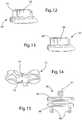
- implant component 10is formed of an endplate 12 having an outer surface 14 and an integral keel 16 extending outwardly away from outer surface 14. Outer surface 14 is designed to engage an adjacent vertebra, with integral keel 16 then being located in a slot suitably formed in the vertebra (see figure 11 for an illustration of a vertebra having a component mounted therein).
- Component 10also includes an inner surface 18 in which an insert 20 is securely located.
- Insert 20includes in this embodiment a concavity 22 therein, but it will be appreciated that insert 20 could instead have a convexity. Received in concavity 22 will be a mating component of the implant, allowing a ball joint movement of a similar endplate engaging an adjacent vertebra.
- the similar endplatecould have a mating convexity provided thereon, either integrally formed or as an insert (like insert 20); or alternatively the similar endplate could be part of a substantially identical component, and a third component could be interposed between the two components to provide articulation between the facing concavities (or convexities) of the components.
- Component 10is designed to help overcome the problem of artifacts which arises when an MRI is taken of a metal orthopedic medical device such as an intervertebral implant typically having two such components.
- MRIis a standard diagnostic tool used to determine the state of the anatomy by visualizing the soft tissue and nerve roots relative to the bony anatomy.
- commonly used metals for orthopedic devicescause MRI artifacts of different degrees.
- the amount of imaging artifactis reduced as the density of the material and magnetic properties of the material are decreased.
- the following biomedical materialscreate imaging artifacts in decreasing order: stainless steel, CoCr alloy, Titanium alloy, ceramics and plastic polymer materials.
- component 10is made to have a reduced amount of imaging artifact, and is thus comprised of two materials: a soft low density material with properties similar to that of the surrounding bone as the main construct foundation, and a harder dense material insert with superior wear properties for the articulating surface areas or parts.
- component 10includes endplate 12 made of a titanium or titanium alloy, and insert 20 made of a material with good articulating properties such as Co-Cr. It will also be noted that insert 20 is reduced to a small area defining the articulating surface of the implant, further helping to reduce the MRI artifact problem.
- insert 20is a shrink-fit into a cylindrical portion 24 of a receiving and mating cavity 26 of endplate 12 located adjacent inner surface 18, though other ways to secure insert 20 as known in the art are possible (such as a sliding/locking ledge design, threads, adhesives, soldering, pressing, etc.).
- the receiving cavity 26 of endplate 12has been optionally designed to pass through outer surface 18, so that a portion of insert 20 is viewable and flat with outer surface 18 as shown in figure 2 .
- insert 20'has a wide flat bottom 28 (as shown best in figure 7 , for example) which mates with the similar shape of cavity 26'.
- This bottom 28is used to secure insert 20' to endplate 12' by use of a suitable adhesive or the like, while the cylindrical areas 30 on the sides of insert 20' in cavity 26' are slightly spaced from the surrounding metal of cylindrical portion 24' of endplate 12' to create an air channel 25 between the two as shown.
- cavity 26'does not extend through to outer surface 14', as shown in figure 6 .
- a layer of Co-Cr, ceramic, carbon or other biocompatible low-friction materialcould also be plasma coated and/or sputtered onto the low-density material of an endplate in a position thereof providing the articulating area (ball and/or socket). This layer of material can then be ground, polished, and/or treated to create the desired low-friction, low-wear articulating surfaces.
- titanium basecould be PEEK, PEKK, or some other structural polymer, carbon reinforced or other similar composite materials, or any other low density structural biomaterial.
- a possible alternativecould be a pyrolitic carbon implant with a smooth articulating surface and roughened bone contacting surfaces similar to that used in hand and wrist implants.
- the conceptis to create a significantly reduced angled/inclined surface to the forward (or posterior) edge of the keel, more pronounced than the large chamfer at the forward end of the keel such as shown in USP 7,204,852 which is designed instead for easier insertion of the keel.
- component 36has a keel 38 with a front edge formed as a pointed edge 40 (or knife edge shape). With pointed edge 40, keel 38 can easily cleave through any excess material located in the bottom end of the channel in the vertebra.
- a similar solutionwould be to reduce the length of the keel by increasing the distance between the posterior (forward) face of the keel and the posterior (bottom) edge of the component. The depth (bottom) of the clearance cut preparation in the bone of the channel for the keel would then remain the same, but the anterior to posterior (or trailing to leading) length of the keel would be reduced on the posterior (forward or leading) end. Doing this would create added clearance between the bone material left in the channel and the posterior (forward) surface of the keel.
- component 44has a keel 46 with a forward U-shape, and preferably an overall an H-shape in plan view.
- This U-shapecan be provided by removing remove material out of the central forward portion of keel 46 so as to create a slot 48 that goes down the front of keel 46. Any obstructive bone material in the channel would fill into the slot 48 and allow keel 46 to fully seat in the formed channel.
- an anterior (rearward) top (outer) corner 52 of a keelmay be proud or protruding out from the anterior (rearward) surface 54 of the bone as shown in figure 11 .
- This exposed metal cornercan cause irritation in surrounding tissue.
- a means for slightly reducing the anterior (rearward) corner profile in the keel in the anterior (rearward) end (as well as posterior end, if desired, as noted above)is desirable.
- One means for slightly reducing the anterior (rearward) corner profile in the keel at the anterior endis to provide a component 58 with a keel 60 in which the anterior (rearward) corner is reduced by a curved rounded surface 62 as shown in figure 12 .
- Another means for slightly reducing the anterior (rearward) corner profile in the keel at the anterior (rearward) endis to provide a component 64 with a keel 66 in which the anterior (rearward) corner is reduced by a chamfer 68 as shown in figure 13 .
- an implant 80has a single central keel 80 on one (superior) endplate 82 and double laterally offset keels 84 on the other (inferior) endplate 86.
- the positions of double keelscould instead be superior, if desired.
- the desired result of a stronger vertebrais as shown in figure 16 where such an implant is used both above and below the depicted vertebra.
- double keel receiving channels 90 in the superior side of vertebra 92which are on either side (laterally offset) from single keel receiving channel 94 in the inferior side of vertebra 92 - leaving a larger amount of bone in the central area of vertebra 92.
- the two components of an implantcould have oppositely offset keels 98a and 98b as depicted in figure 17 .
- offset keels 84'are divergent at a certain angle as shown in figure 18
- offset keels 84"are convergent as shown in figure 19 .
- the enhanced benefit of having divergent/convergent keel designsis to prevent loosening of the associated endplate with that type of geometry.
- the divergent or convergent angles of the keelswould add greater resistance to movement in the axial direction and become less likely to be loosened over time.
- the keels of paired endplatescould be both convergent or both divergent, or one convergent and one divergent.
- an implant component 100having an endplate 102 and insert 104.
- a raised plate edge or shelf-like feature 106is provided at the anterior (outer) end of component 102.
- the presence of raised edge 106serves as a means for retarding bone growth/formation between the adjacent vertebrae by its presence and large distance which must then be bridged.
- tissueincluding bone tissue, tends to grow into and anchor to rough surfaces of titanium implants but does not adhere to certain plastics or other materials.
- this raised anterior edge 106 of endplate 104is preferably polished to a smooth surface finish.
- the raised anterior edge 106is treated with a suitable surface coating since bone fusion is usually related to the blood supply and cell formation/cell growth for a given area.
- a suitable surface coatingcould be placed in this area to prevent bone forming and hence undesirable bone fusion.
- an anti-blood coagulating surface or agentcould be integral to raised edge 106.
- Raised edge 106could also be designed to hold cement or other material that would contain an anticoagulant or anti-cellular growth inhibiting agent.
- the bone cement, implant coating, and/or implant edge fusion block featurecould also contain a controlled release anti-inflammatory agent to retard the healing process and thus retard bone growth in that area of undesired fusion.
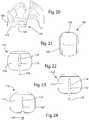
- the keel or other fixation feature of an implantcould also be modular as depicted in figures 22-24 .
- the endplateis placed into the intervertebral space first; and then the fixation element, such as a keel, is moved through the plate into a mating slot provided in the bone. Finally, that fixation element is then locked to the plate by a suitable mechanical means such as a fastener or set screw.
- a suitable mechanical meanssuch as a fastener or set screw.
- Keel 116has a "ball" shape at one end, with the vertebra thus having a cutout or slot designed to receive this ball shape. With this shape, keel 116 is more stably held in place longitudinally, without removing so much of the vertebrae.
- keel geometries or configurationsare possible, such as the "Xmas Tree” shape of keel 116' of component 110' depicted in figure 23 , or the snake-shaped keel 116" of component 110" depicted in figure 24 . It would also be alternatively possible to put the keel in place first, and then attach the endplate to the keel in a similar manner.
- the shape of the keelcan be slightly wedged in one dimension (in the forward or insertion direction) as shown by keel 122 in figure 25 (or keel 126 in figure 27 ); or in two dimensions as shown by keel 124 in figure 26 .
- the wedge shapeis regular and symmetrical, but it could also be irregular and unsymmetrical.
- the wedge shapecan go over the whole length of the keel or just in a short section of the keel.
- keel 126The wedge shape of the keel does not need to be solid, and thus could be hollow as shown by keel 126 in figure 27 .
- keel 126is open from the top, and from the anterior (outer) end; and in another embodiment the keel could also be open from the front (forward end) as shown schematically by keels 128 in figure 28 .
- Keel 126 or 128could also be open from the sides as desired; and it will be thus appreciated that combinations of different openings are also possible.
- a keel with stepsis also desirable, as shown by keels 130, 132 and 134 shown in respective figures 29, 30 and 31 .
- keel 130it consists of respective small parts 130' that are grouped together to build the keel-shape.
- keel 134also provides special surfaces preventing the backing out by the keel, namely angled out fin or surface 134' and angled in surface 134", even though keel 134 is easy to insert in one (forward) direction as surface 134' has a ramping action in that direction.
- the vertical cross-sectional shape of a keelis typically a simple rectangular shape, the vertical cross-sectional geometry of a keel could also be modified to enhance fixation and/or stability in the bone.
- This cross sectioncan vary, as it can be symmetrical or asymmetrical.
- the horizontal cross-sectional shape of a keelis also typically a simple rectangular shape
- the horizontal cross-sectional geometry of a keelcould also be modified to enhance fixation and/or stability in the bone.
- This cross sectioncan vary, as it can be symmetrical or asymmetrical.
- the thicknesses of the keelscan vary. Some examples of differing thickness keels are shown in the drawings as described hereafter with reference to the following figures.
- FIG. 62-63Depicted in figures 62-63 is an instrument broadly similar to those disclosed in the above noted published applications, and thus including a trial implant 150 having an adjustable stop 152.
- the trial implant 150includes a top slot 154 at the location above which a keel slot is to be cut in a superior (or inferior) vertebra when trial implant 150 is located between two vertebrae. It will be noted that trial implant also has two bottom slots (not shown) similar to top slot 150, but at locations where offset keel slots are to be cut in the inferior vertebra - so that trial implant 150 is thus used to cut the slots for an implant such as disclosed in figure 15 .
- a guide 156Extending away from trial implant 150 is a guide 156 which is used to guide trial implant into the intervertebral space between two adjacent vertebrae after the disc is removed and to which adjustable stop 152 is threadedly engaged.
- Guide 156has slots corresponding to those in trial implant 150, such as top slot 158.
- Slots 154 and 158serve to guide saw cutting tool 160 therealong, where cutting tool 160 is rapidly reciprocated by a suitable motor 162 shown schematically and which can take the form of various power tools as known in the art. Rapid reciprocation of saw cutting tool 160 is effective to produce is a reduced impact on the vertebral bone due to the acceleration to mass relationship between cutting tool 160 and the vertebral bone.
- cutting tool 160includes three thin saw blades 162 which extend at a proximal edge thereof along slots in guide 156 and trial implant 150, such as slots 158 and 154. At the distal edge, saw blades 162 have suitable cutting teeth 164, which at a leading or forward end form a ramp for easier starting into the vertebra. The insertion depth of cutting blades into the vertebrae is controlled by adjusting the position of adjustable stop 152.
- cutting tool 160has been shown with three blades, it will be appreciated that only a single blade could be provided to cut each slot individually as needed. It would also be possible to provide a blade more like a chisel but with cutting teeth just at the front. Different interchangeable blades would also be possible, if a narrower or wider, or higher or lower, or deeper or shallower, cut slot was desired. If desired, motor 162 can be dispensed with, and the blade or blades moved by hand with the same guidance.
- the material of the bladesis preferably a suitable metal, but ceramic or plastic blades, or even a diamond cutting blade, would also be possible. If desired or necessary, a coatings to reduce friction could be used with the cutting blades.
- Cutting tool 168includes chisel blades 170 and would thus be used to chisel three slots simultaneously.
Landscapes
- Health & Medical Sciences (AREA)
- Engineering & Computer Science (AREA)
- Biomedical Technology (AREA)
- Life Sciences & Earth Sciences (AREA)
- Orthopedic Medicine & Surgery (AREA)
- Surgery (AREA)
- Oral & Maxillofacial Surgery (AREA)
- Heart & Thoracic Surgery (AREA)
- Animal Behavior & Ethology (AREA)
- General Health & Medical Sciences (AREA)
- Public Health (AREA)
- Veterinary Medicine (AREA)
- Transplantation (AREA)
- Neurology (AREA)
- Medical Informatics (AREA)
- Molecular Biology (AREA)
- Dentistry (AREA)
- Nuclear Medicine, Radiotherapy & Molecular Imaging (AREA)
- Vascular Medicine (AREA)
- Cardiology (AREA)
- Physical Education & Sports Medicine (AREA)
- Prostheses (AREA)
Abstract
Description
- Historically, when it was necessary to completely remove a disc from between adjacent vertebrae, the conventional procedure was to fuse the adjacent vertebrae together. This "spinal fusion" procedure, which is still in use today, is a widely accepted surgical treatment for symptomatic lumbar and cervical degenerative disc disease.
- More recently, there have been important developments in the field of disc replacement, namely disc arthoplasty, which involves the insertion of an artificial intervertebral disc implant into the intervertebral space between adjacent vertebrae. Such a disc implant allows limited universal movement of the adjacent vertebrae with respect to each other. The aim of total disc replacement is to remove pain generation (caused by a degenerated disc), restore anatomy (disc height), and maintain mobility in the functional spinal unit so that the spine remains in an adapted sagittal balance. Sagittal balance is defined as the equilibrium of the trunk with the legs and pelvis to maintain harmonious sagittal curves and thus the damping effect of the spine. In contrast with fusion techniques, total disc replacement preserves mobility in the motion segment and mimics physiologic conditions.
- One such intervertebral implant includes an upper part that can communicate with an adjacent vertebrae, a lower part that can communicate with an adjacent vertebrae, and an insert located between these two parts. To provide an anchor to the adjacent vertebrae, each part includes a vertically extending keel. Examples of this type of implant are disclosed in
U.S. Patent No. 5,314,477 (Marnay ) andU.S. Patent No. 7,204,852 (Marnay et al. ), which are hereby incorporated by reference. - While this and other known implants represent improvements in the art of artificial intervertebral implants, there exists a continuing need for improvements for these types of implants.
- It will also be noted that in order to provide a keel slot in a vertebra, a cutting of the bone needs to be performed. Typically the cut is made by chiseling, drilling or milling. Combinations of these procedures are possible too. However, where a chisel cut is made using a chisel and a mallet, quite high forces are applied in direction of the cut. With drilling, lesser forces are applied, but the drill can slip of or bend during drilling. With milling, a precise cut is made without high forces, but the milling tool needs to have a certain diameter, because otherwise it will brake during milling so milling is not always possible where a long narrow cut is required. Thus, a procedure used to perform narrow cuts without applying high forces is desirable. Exemplary of such prior art devices and methods are those disclosed in USPA
2004-0215198 (Marnay et al. ) and USPA2006-0064100 (Bertagnoli et al. ), which are hereby incorporated by reference. - In accordance with a disclosed embodiment, an intervertebral implant includes two components each having an outer surface for engaging an adjacent vertebra and an inner surface. A keel extends from the outer surface of one component and is designed to be disposed in a slot provided in the adjacent vertebra. This keel extends in a plane which is perpendicular to the outer surface. In one preferred embodiment, there are a pair of keels extending from the other outer surface, which are preferably offset laterally from one another. The pair of keels are preferably symmetrically located on either side of a vertical mid-plane of the outer surface, and are divergent or convergent with respect to each other.
- Also in accordance with a disclosed embodiment, an intervertebral implant component of an intervertebral implant includes an outer surface for engaging an adjacent vertebra and an inner surface. A keel extends from the outer surface and is designed to be disposed in a slot provided in the adjacent vertebra. An anterior shelf is also provided at an anterior end of the outer surface, and this anterior shelf extends vertically away from the inner surface in order to help prevent bone growth from the adjacent vertebra towards the inner surface. In accordance with preferred embodiments, the anterior shelf can have a forward surface which is angled, an exterior surface which is polished, and/or a surface treatment which helps prevent bone growth thereon.
- Further in accordance with disclosed embodiments, various materials and forms of construction of the component are disclosed. Posterior and/or anterior reductions of the keel are possible for different benefits. The body strength of the vertebra with keel slots on both the superior and inferior surfaces can also be stronger if the keels of the associated components requiring slots are laterally offset. Embodiments of components with modular keels, as well as a variety of advantageous keel shapes (both in horizontal cross section and vertical cross section) are also disclosed.
- It will also be appreciated that various combinations of the features disclosed hereafter for a component, and hence for the implant, are also possible as desired.
- An instrument for cutting of keel slots with a saw blade, and in particular for cutting multiple slots simultaneously, is also provided.
- Other features and advantages of the present invention are stated in or apparent from detailed descriptions of presently preferred embodiments of the inventions found hereinbelow.
Figure 1 is a bottom, right and back perspective view of an implant component in accordance with the present invention.Figure 2 is a top and front perspective view of the implant component depicted infigure 1 .Figure 3 is cross-sectional side elevational perspective view of the implant component offigure 1 taken along the line 3-3 offigure 1 .Figure 4 is an exploded front, bottom, left side perspective view of the implant component offigure 1 .Figure 5 is a bottom and back perspective view of a second embodiment of an implant component in accordance with the present invention.Figure 6 is a top, front and left side perspective view of the implant component depicted infigure 5 .Figure 7 is cross-sectional side elevational perspective view of the implant component offigure 5 taken along the line 7-7 offigure 5 .Figure 8 is an exploded bottom, right and back perspective view of the implant component offigure 5 .Figure 9 is a top, front and left side perspective view of an implant component with a pointed keel.Figure 10 is a top, back and right side perspective view of an implant component with an H-shaped keel.Figure 11 is a top, back and left side perspective view of an implant component inserted in a vertebra with an anterior corner of the keel exposed.Figure 12 is a top, back and left side perspective view of an implant component with a keel with a rounded top corner.Figure 13 is a top, back and left side perspective view of an implant component with a keel with a chamfered top corner.Figure 14 is a top, back and left side view of a vertebra with symmetrically cut slots for centered keels.Figure 15 is a top and front perspective view of mating implant components with two keels of one component offset from the single keel of the other component.Figure 16 is top, back and left side view of a vertebra with offset cut slots for the keels of the components depicted infigure 15 .Figure 17 a front view of mating implant components with one keel of one component offset from the other keel of the other component.Figure 18 is a front and top perspective view of an implant component with two keels that are divergent.Figure 19 is a front and top perspective view of an implant component with two keels that are convergent.Figure 20 is a left side view of an implant component having a bone growth retarding plate which is inserted in a vertebra.Figure 21 is a top plan view of the implant component offigure 20 .Figures 22-24 are top plan views of implant components with different modular keel shapes retainable therein.Figures 25-31 are top, back and left side perspective views of implant components with differently shaped keels for better longitudinal retention.Figures 32-51 are front elevation views of different keel shapes.Figures 52-58 are top plan views of different keel shapes.Figures 59-61 are schematic front elevation views of mating implant components with different thicknesses of keels.Figure 62 is a top, back and right side perspective view of an instrument used to cut keel slots.Figure 63 is a top, front and right side perspective view of the cutting tool depicted infigure 62 .Figure 64 is a top, front and right side perspective view of an alternative cutting tool for use with the instrument depicted infigure 62 .- With reference now to the drawings in which like numerals represent like elements throughout the views, a
first component 10 of an intervertebral implant for total disc replacement according to the present invention is depicted inFigures 1-4 . Theimplant including component 10 is primarily designed for insertion between adjacent vertebrae from an anterior direction. Thus, reference will sometimes be made to anterior and posterior directions for convenience. However, it will be appreciated that insertion from other directions is possible, and hence the referenced directions would thus be similarly changed. In addition, terms such as front/back, forward/rearward, left/right and top/bottom may be used to identify directions as depicted in the figures and/or as the implant is used relative to any insertion direction, even though the "front" may be facing anteriorly or posteriorly depending on the direction of insertion used. Thus, these terms are used for illustration purposes only and not as limiting terms for the invention. - In this embodiment,
implant component 10 is formed of anendplate 12 having anouter surface 14 and anintegral keel 16 extending outwardly away fromouter surface 14.Outer surface 14 is designed to engage an adjacent vertebra, withintegral keel 16 then being located in a slot suitably formed in the vertebra (seefigure 11 for an illustration of a vertebra having a component mounted therein).Component 10 also includes aninner surface 18 in which aninsert 20 is securely located.Insert 20 includes in this embodiment aconcavity 22 therein, but it will be appreciated thatinsert 20 could instead have a convexity. Received inconcavity 22 will be a mating component of the implant, allowing a ball joint movement of a similar endplate engaging an adjacent vertebra. The similar endplate could have a mating convexity provided thereon, either integrally formed or as an insert (like insert 20); or alternatively the similar endplate could be part of a substantially identical component, and a third component could be interposed between the two components to provide articulation between the facing concavities (or convexities) of the components. Component 10 is designed to help overcome the problem of artifacts which arises when an MRI is taken of a metal orthopedic medical device such as an intervertebral implant typically having two such components. During spine surgery, MRI is a standard diagnostic tool used to determine the state of the anatomy by visualizing the soft tissue and nerve roots relative to the bony anatomy. However, commonly used metals for orthopedic devices cause MRI artifacts of different degrees. The amount of imaging artifact is reduced as the density of the material and magnetic properties of the material are decreased. For example, the following biomedical materials create imaging artifacts in decreasing order: stainless steel, CoCr alloy, Titanium alloy, ceramics and plastic polymer materials.- The design of
component 10 is made to have a reduced amount of imaging artifact, and is thus comprised of two materials: a soft low density material with properties similar to that of the surrounding bone as the main construct foundation, and a harder dense material insert with superior wear properties for the articulating surface areas or parts. In particular,component 10 includesendplate 12 made of a titanium or titanium alloy, and insert 20 made of a material with good articulating properties such as Co-Cr. It will also be noted thatinsert 20 is reduced to a small area defining the articulating surface of the implant, further helping to reduce the MRI artifact problem. - Conveniently, insert 20 is a shrink-fit into a
cylindrical portion 24 of a receiving andmating cavity 26 ofendplate 12 located adjacentinner surface 18, though other ways to secureinsert 20 as known in the art are possible (such as a sliding/locking ledge design, threads, adhesives, soldering, pressing, etc.). In this embodiment, it will be appreciated that the receivingcavity 26 ofendplate 12 has been optionally designed to pass throughouter surface 18, so that a portion ofinsert 20 is viewable and flat withouter surface 18 as shown infigure 2 . - Depicted in
figures 5-8 is an alternative embodiment of a component 10' which is broadly similar tocomponent 10 and whose similar elements will thus be identified with the same reference numerals followed by a prime ('). In this embodiment of component 10', insert 20' has a wide flat bottom 28 (as shown best infigure 7 , for example) which mates with the similar shape of cavity 26'. This bottom 28 is used to secure insert 20' to endplate 12' by use of a suitable adhesive or the like, while thecylindrical areas 30 on the sides of insert 20' in cavity 26' are slightly spaced from the surrounding metal ofcylindrical portion 24' of endplate 12' to create anair channel 25 between the two as shown. It will also be noted that cavity 26' does not extend through to outer surface 14', as shown infigure 6 . - Other alternatives to the embodiments above could include any number of hard materials and/or surface treatments to be used for the articulating function, such as a ceramic insert, a titanium nitride coated hardened surface, a diamond coated surface such as a DLC (amorphic diamond like carbon), or any other type surface treatment or material for medical use that provides a hardened superior wear surface. A layer of Co-Cr, ceramic, carbon or other biocompatible low-friction material could also be plasma coated and/or sputtered onto the low-density material of an endplate in a position thereof providing the articulating area (ball and/or socket). This layer of material can then be ground, polished, and/or treated to create the desired low-friction, low-wear articulating surfaces.
- Alternatives to the titanium base could be PEEK, PEKK, or some other structural polymer, carbon reinforced or other similar composite materials, or any other low density structural biomaterial. A possible alternative could be a pyrolitic carbon implant with a smooth articulating surface and roughened bone contacting surfaces similar to that used in hand and wrist implants.
- It has been found that during surgical implantation final seating of the implant endplates has in a few cases proven to be difficult. It is believed that during surgical preparation (typically chiseling, or cutting or drilling) of the keel receiving channel in the vertebral body, not all of the cut bone material is removed but instead some material may be forced to the posterior (or closed) end of the channel by the action of the chisel or the like. This material is then inadvertently left to form an obstruction to the full seating of the keel at the closed end of the channel, resulting in a suboptimal implant position. In order to alleviate this problem, a number of designs are proposed with means designed to accommodate for such excess material, as by a posterior (forward) reduction of the keel. The concept is to create a significantly reduced angled/inclined surface to the forward (or posterior) edge of the keel, more pronounced than the large chamfer at the forward end of the keel such as shown in USP
7,204,852 which is designed instead for easier insertion of the keel. - Thus, a means for accommodating excess material in accordance with the present invention is shown in
figure 9 . In this embodiment,component 36 has akeel 38 with a front edge formed as a pointed edge 40 (or knife edge shape). With pointededge 40,keel 38 can easily cleave through any excess material located in the bottom end of the channel in the vertebra. A similar solution would be to reduce the length of the keel by increasing the distance between the posterior (forward) face of the keel and the posterior (bottom) edge of the component. The depth (bottom) of the clearance cut preparation in the bone of the channel for the keel would then remain the same, but the anterior to posterior (or trailing to leading) length of the keel would be reduced on the posterior (forward or leading) end. Doing this would create added clearance between the bone material left in the channel and the posterior (forward) surface of the keel. - Still another means for accommodating excess material is shown in
figure 10 . In this embodiment,component 44 has akeel 46 with a forward U-shape, and preferably an overall an H-shape in plan view. This U-shape can be provided by removing remove material out of the central forward portion ofkeel 46 so as to create aslot 48 that goes down the front ofkeel 46. Any obstructive bone material in the channel would fill into theslot 48 and allowkeel 46 to fully seat in the formed channel. - It has also been found that in rare cases, due to the irregular anatomy of some patients and/or in cases of extreme anterior (rearward) positioning of the implant, an anterior (rearward) top (outer)
corner 52 of a keel may be proud or protruding out from the anterior (rearward) surface 54 of the bone as shown infigure 11 . This exposed metal corner can cause irritation in surrounding tissue. For that reason, a means for slightly reducing the anterior (rearward) corner profile in the keel in the anterior (rearward) end (as well as posterior end, if desired, as noted above) is desirable. - One means for slightly reducing the anterior (rearward) corner profile in the keel at the anterior end is to provide a
component 58 with akeel 60 in which the anterior (rearward) corner is reduced by a curvedrounded surface 62 as shown infigure 12 . Another means for slightly reducing the anterior (rearward) corner profile in the keel at the anterior (rearward) end is to provide acomponent 64 with akeel 66 in which the anterior (rearward) corner is reduced by achamfer 68 as shown infigure 13 . - Other embodiments could include an angled surface or other feature to reduce keel material in this area.
- In small or weakened vertebrae, weakening of the bone due to the alignment in the central axis of the spine of
keel receiving channels vertebra 72 in a multi-level (consecutive) disc replacement case will occur as shown infigure 14 . This occurrence would leave a much smaller central portion of the bone invertebra 72, possibly creating a weaker bony construct surrounding the two keels of the two adjacent implants. Thus, it was determined that designs where the keels would be offset in different locations would be desirable for leaving a more intact stronger bone construct. - One means for offsetting keels in adjacent implants is depicted in
figures 15-16 . In this embodiment, animplant 80 has a singlecentral keel 80 on one (superior)endplate 82 and double laterally offset keels 84 on the other (inferior)endplate 86. Obviously, the positions of double keels could instead be superior, if desired. However, the desired result of a stronger vertebra is as shown infigure 16 where such an implant is used both above and below the depicted vertebra. In particular, there are double keel receiving channels 90 in the superior side ofvertebra 92 which are on either side (laterally offset) from singlekeel receiving channel 94 in the inferior side of vertebra 92 - leaving a larger amount of bone in the central area ofvertebra 92. - As a variation of this design, the two components of an implant could have oppositely offset keels 98a and 98b as depicted in
figure 17 . - Another variations of this design could include embodiments wherein offset keels 84' are divergent at a certain angle as shown in
figure 18 , or offsetkeels 84" are convergent as shown infigure 19 . The enhanced benefit of having divergent/convergent keel designs is to prevent loosening of the associated endplate with that type of geometry. The divergent or convergent angles of the keels would add greater resistance to movement in the axial direction and become less likely to be loosened over time. Thus, it will be appreciated that such divergent or convergent keel designs would be beneficial even when not used in consecutive implants; and thus the keels of paired endplates could be both convergent or both divergent, or one convergent and one divergent. - It has been found that in some cases of total disc arthroplasty in the neck, bone has grown across the implant located in between the vertebral bodies so that the adjacent vertebrae have become fused in spite of the articulating implant provided therebetween. Mostly this problem occurs in the anterior portion of the implant. Therefore, in order to prevent this from happening, a means is added to the implant endplates to retard or stop bone from bridging over the implant.
- Depicted in
figures 20-21 is animplant component 100 having anendplate 102 and insert 104. Provided at the anterior (outer) end ofcomponent 102 is a raised plate edge or shelf-like feature 106. The presence of raisededge 106 serves as a means for retarding bone growth/formation between the adjacent vertebrae by its presence and large distance which must then be bridged. - It will also be appreciated that tissue, including bone tissue, tends to grow into and anchor to rough surfaces of titanium implants but does not adhere to certain plastics or other materials. Thus, this raised
anterior edge 106 ofendplate 104 is preferably polished to a smooth surface finish. - Alternatively, the raised
anterior edge 106 is treated with a suitable surface coating since bone fusion is usually related to the blood supply and cell formation/cell growth for a given area. For example, an anti-cellular coating could be placed in this area to prevent bone forming and hence undesirable bone fusion. Alternatively, an anti-blood coagulating surface or agent could be integral to raisededge 106. Raisededge 106 could also be designed to hold cement or other material that would contain an anticoagulant or anti-cellular growth inhibiting agent. The bone cement, implant coating, and/or implant edge fusion block feature could also contain a controlled release anti-inflammatory agent to retard the healing process and thus retard bone growth in that area of undesired fusion. - In order to improve fixation of a keel while avoiding removing of some of the vertebra, the keel or other fixation feature of an implant could also be modular as depicted in
figures 22-24 . With such an embodiment, the endplate is placed into the intervertebral space first; and then the fixation element, such as a keel, is moved through the plate into a mating slot provided in the bone. Finally, that fixation element is then locked to the plate by a suitable mechanical means such as a fastener or set screw. Thus, depicted infigure 22 is animplant component 110 having anendplate 112 in which there is acentral aperture 114 shaped to matingly receive akeel 116. As shown, setscrew 118 is used to securekeel 116 in place inaperture 114 ofendplate 112 oncekeel 116 is located properly.Keel 116 has a "ball" shape at one end, with the vertebra thus having a cutout or slot designed to receive this ball shape. With this shape,keel 116 is more stably held in place longitudinally, without removing so much of the vertebrae. - Other possible keel geometries or configurations are possible, such as the "Xmas Tree" shape of keel 116' of component 110' depicted in
figure 23 , or the snake-shapedkeel 116" ofcomponent 110" depicted infigure 24 . It would also be alternatively possible to put the keel in place first, and then attach the endplate to the keel in a similar manner. - A variety of different keel shapes are also possible to enhance the ability of the keel to be retained (or not to loosen as easily) in the slot cut into the vertebra. For example, the shape of the keel can be slightly wedged in one dimension (in the forward or insertion direction) as shown by
keel 122 infigure 25 (orkeel 126 infigure 27 ); or in two dimensions as shown bykeel 124 infigure 26 . Typically the wedge shape is regular and symmetrical, but it could also be irregular and unsymmetrical. The wedge shape can go over the whole length of the keel or just in a short section of the keel. The wedge shape of the keel does not need to be solid, and thus could be hollow as shown bykeel 126 infigure 27 . In this embodiment,keel 126 is open from the top, and from the anterior (outer) end; and in another embodiment the keel could also be open from the front (forward end) as shown schematically bykeels 128 infigure 28 .Keel - A keel with steps is also desirable, as shown by
keels figures 29, 30 and 31 . In the case ofkeel 130, it consists of respective small parts 130' that are grouped together to build the keel-shape. It will be appreciated thatkeel 134 also provides special surfaces preventing the backing out by the keel, namely angled out fin or surface 134' and angled insurface 134", even thoughkeel 134 is easy to insert in one (forward) direction as surface 134' has a ramping action in that direction. - While the vertical cross-sectional shape of a keel is typically a simple rectangular shape, the vertical cross-sectional geometry of a keel could also be modified to enhance fixation and/or stability in the bone. This cross section can vary, as it can be symmetrical or asymmetrical. Some examples of different vertical cross-sectional shapes, and combinations of vertical cross-sectional shapes, are shown in the drawings as described hereafter with reference to the noted figures.
- Figure 32:
- bowed on each side;
- Figure 33:
- angled asymmetrically on each top side;
- Figure 34:
- pointed at the top side;
- Figure 35:
- angled to one side;
- Figure 36:
- top edge angled;
- Figure 37:
- right angle triangle shaped;
- Figure 38:
- round nosed;
- Figure 39:
- one side inwardly angled;
- Figure 40:
- one side inwardly bowed;
- Figure 41:
- both sides inwardly bowed;
- Figure 42:
- top edge angled to one side which is angled inward;
- Figure 43:
- angled on each top side, and each side angled inward;
- Figure 44:
- both sides angled inward;
- Figure 45:
- both sides angled outward;
- Figure 46:
- diamond shaped;
- Figure 47:
- both ends chamfered;
- Figure 48:
- parallelogram shaped;
- Figure 49:
- elongated hexagonal shaped;
- Figure 50:
- both ends stepped at both sides; and
- Figure 51:
- elongated pentagon shaped.
- Also, while the horizontal cross-sectional shape of a keel is also typically a simple rectangular shape, the horizontal cross-sectional geometry of a keel could also be modified to enhance fixation and/or stability in the bone. This cross section can vary, as it can be symmetrical or asymmetrical. Some examples of different horizontal cross-sectional shapes, besides those already mentioned above, and combinations of horizontal cross-sectional shapes, are shown in the drawings as described hereafter with reference to the following figures.
- Figure 52:
- angled symmetrically toward the leading edge;
- Figure 53:
- angled symmetrically toward the leading edge to a point;
- Figure 54:
- rounded leading edge;
- Figure 55:
- sharply angled to one side leading edge;
- Figure 56:
- a series of angled leading edges;
- Figure 57:
- diamond shaped with trailing edge blunted; and
- Figure 58:
- asymmetrically bowed.
- Further, where more than one keel is present on one of the two components the thicknesses of the keels can vary. Some examples of differing thickness keels are shown in the drawings as described hereafter with reference to the following figures.
- Figure 59:
- the top keels have a small and a large thickness, while the bottom keel has an intermediate thickness;
- Figure 60:
- the bottom keels have a small and an intermediate thickness, while the top keel has a large thickness;
- Figure 61:
- the top keels have a small and a large thickness, while the bottom keels have a small intermediate thickness and a large intermediate thickness.
- As noted above, instruments and methods have been disclosed for cutting keel receiving slots in a vertebra, or in two adjacent vertebrae. Typical of such devices and methods are those shown and described in USPA
2004-0215198 (Marnay et al. ) and USPA2006-0064100 Bertagnoli et al. ) which primarily disclose chiseling or burring embodiments. - Depicted in
figures 62-63 is an instrument broadly similar to those disclosed in the above noted published applications, and thus including atrial implant 150 having anadjustable stop 152. Thetrial implant 150 includes atop slot 154 at the location above which a keel slot is to be cut in a superior (or inferior) vertebra whentrial implant 150 is located between two vertebrae. It will be noted that trial implant also has two bottom slots (not shown) similar totop slot 150, but at locations where offset keel slots are to be cut in the inferior vertebra - so thattrial implant 150 is thus used to cut the slots for an implant such as disclosed infigure 15 . - Extending away from
trial implant 150 is aguide 156 which is used to guide trial implant into the intervertebral space between two adjacent vertebrae after the disc is removed and to whichadjustable stop 152 is threadedly engaged.Guide 156 has slots corresponding to those intrial implant 150, such astop slot 158.Slots saw cutting tool 160 therealong, where cuttingtool 160 is rapidly reciprocated by asuitable motor 162 shown schematically and which can take the form of various power tools as known in the art. Rapid reciprocation ofsaw cutting tool 160 is effective to produce is a reduced impact on the vertebral bone due to the acceleration to mass relationship between cuttingtool 160 and the vertebral bone. - It will be appreciated that cutting
tool 160 includes three thin sawblades 162 which extend at a proximal edge thereof along slots inguide 156 andtrial implant 150, such asslots blades 162 have suitable cuttingteeth 164, which at a leading or forward end form a ramp for easier starting into the vertebra. The insertion depth of cutting blades into the vertebrae is controlled by adjusting the position ofadjustable stop 152. - While cutting
tool 160 has been shown with three blades, it will be appreciated that only a single blade could be provided to cut each slot individually as needed. It would also be possible to provide a blade more like a chisel but with cutting teeth just at the front. Different interchangeable blades would also be possible, if a narrower or wider, or higher or lower, or deeper or shallower, cut slot was desired. If desired,motor 162 can be dispensed with, and the blade or blades moved by hand with the same guidance. The material of the blades is preferably a suitable metal, but ceramic or plastic blades, or even a diamond cutting blade, would also be possible. If desired or necessary, a coatings to reduce friction could be used with the cutting blades. - Depicted in
figure 64 is anothercutting tool 168 usable in place of cuttingtool 160 and withtrial implant 150. Cuttingtool 168 includeschisel blades 170 and would thus be used to chisel three slots simultaneously. - Various advantageous features have been described above with respect to various embodiments. Such advantageous features are also considered to be usable together, rather than singly as typically depicted and described.
- While the present invention has been described with respect to exemplary embodiments thereof, it will be understood by those of ordinary skill in the art that variations and modifications can be effected within the scope and spirit of the invention.
- Item 1: An intervertebral implant comprising: a first component having an outer surface for engaging an adjacent vertebra and an inner surface, and a keel extending from the outer surface which is disposed in a slot provided in the adjacent vertebra, said keel extending in a plane which is substantially perpendicular to said outer surface; and a second component having an outer surface for engaging an adjacent vertebra and an inner surface, and a pair of keels extending from the outer surface which are disposed in respective slots provided in the adjacent vertebra, said keels extending on either side of a vertical mid-plane of said outer surface.
- Item 2: An intervertebral implant component as described in item 1, wherein said pair of keels are symmetrically located on either side of the vertical mid-plane of said outer surface.
- Item 3: An intervertebral implant component as described in item 2, wherein said pair of keels are divergent with respect to each other.
- Item 4: An intervertebral implant component as described in item 2, wherein said pair of keels are convergent with respect to each other.
- Item 5: An intervertebral implant component as described in item 1, wherein said pair of keels are divergent with respect to each other.
- Item 6: An intervertebral implant component as described in item 1, wherein said pair of keels are convergent with respect to each other.
- Item 7: An intervertebral implant component as described in item 2, wherein said pair of keels have a leading knife edge.
- Item 8: An intervertebral implant component comprising: an outer surface for engaging an adjacent vertebra and an inner surface; a keel extending from the outer surface which is disposed in a slot provided in the adjacent vertebra; and an anterior shelf provided at an anterior end of said outer surface and extending vertically away from said inner surface which helps to prevent bone growth from the adjacent vertebra towards said inner surface.
- Item 9: An intervertebral implant component as described in item 8, wherein said anterior shelf has a forward surface which is angled.
- Item 10: An intervertebral implant component as described in item 8, wherein an exterior surface of said anterior shelf is polished.
- Item 11: An intervertebral implant component as described in item 8, wherein an exterior surface of said anterior shelf is provided with a surface treatment which helps prevent bone growth thereon.
Claims (15)
- An intervertebral implant for insertion into an intervertebral disc space between two adjacent vertebrae along an insertion direction, the implant comprising:a component having an outer surface for engaging one of the adjacent vertebrae and an inner surface opposite the outer surface; anda fixation element extending from the outer surface, said fixation element extending in a plane which is substantially perpendicular to said outer surface and having a leading end in the insertion direction and a trailing end opposite the insertion direction, the fixation element defining a recess in the trailing end.
- The implant of claim 1, wherein the fixation element includes opposed side walls that are substantially parallel to each other and elongate along the insertion direction, wherein the side walls flare away from each along a direction opposite the insertion direction so as to define the trailing end.
- The implant of claim 1, wherein the recess extends into the trailing end in the insertion direction, terminates between the leading and trailing ends and extends through the fixation element in a transverse direction that is perpendicular to the insertion direction and terminates at the outer surface.
- The implant of claim 1, wherein the fixation element is integral with the component.
- The implant of claim 1, wherein the fixation element extends from the outer surface on a vertical mid-plane of the outer surface.
- The implant of claim 1, wherein the fixation element comprises a keel.
- The implant of claim 1, wherein the component is a first component, the implant further comprising a second component having an outer surface for engaging the other of the two adjacent vertebrae and an inner surface opposite the outer surface, and a pair of fixation elements extending from the outer surface, said pair of fixation elements extending on either side of a vertical mid-plane of said outer surface.
- The implant of claim 7, wherein the fixation element of the first component is centered with respect to the pair of fixation elements of the second component.
- The implant of claim 7, wherein each of the pair of fixation elements of the second component is offset from the fixation element of the first component in the lateral direction.
- The implant of claim 7, wherein the fixation element of the first component extends from the outer surface on a vertical mid-plane of the outer surface.
- The implant of claim 7, further including an insert residing between the first and second components.
- The implant of claim 7, wherein the first component includes a concave surface, and the insert includes a convex surface for engaging the concave surface of the first component.
- The intervertebral of claim 7, wherein the pair of fixation elements each have a second leading end in the insertion direction and a second trailing end opposite the insertion direction, said pair of fixation elements each defining a second recess in the second trailing end.
- The implant of claim 13, wherein the pair of fixation elements each have opposed side walls that are substantially parallel to each other and elongate along the insertion direction, wherein the opposed side walls flare away from each other along a direction opposite the insertion direction so as to define the second trailing end.
- The implant of claim 14 wherein the second recess of each of the pair of fixation elements extends into the second trailing end in the insertion direction, terminates between the second leading and trailing ends and extends through each of the pair of fixation elements in a transverse direction that is perpendicular to the insertion direction and terminates at the second outer surface.
Applications Claiming Priority (3)
| Application Number | Priority Date | Filing Date | Title |
|---|---|---|---|
| US83259506P | 2006-07-24 | 2006-07-24 | |
| PCT/US2007/074218WO2008014258A2 (en) | 2006-07-24 | 2007-07-24 | Intervertebral implant with keel |
| EP07813286.7AEP2043563B1 (en) | 2006-07-24 | 2007-07-24 | Intervertebral implant with keel |
Related Parent Applications (1)
| Application Number | Title | Priority Date | Filing Date |
|---|---|---|---|
| EP07813286.7ADivisionEP2043563B1 (en) | 2006-07-24 | 2007-07-24 | Intervertebral implant with keel |
Publications (1)
| Publication Number | Publication Date |
|---|---|
| EP3628244A1true EP3628244A1 (en) | 2020-04-01 |
Family
ID=38982262
Family Applications (2)
| Application Number | Title | Priority Date | Filing Date |
|---|---|---|---|
| EP19186610.2APendingEP3628244A1 (en) | 2006-07-24 | 2007-07-24 | Intervertebral implant with keel |
| EP07813286.7AActiveEP2043563B1 (en) | 2006-07-24 | 2007-07-24 | Intervertebral implant with keel |
Family Applications After (1)
| Application Number | Title | Priority Date | Filing Date |
|---|---|---|---|
| EP07813286.7AActiveEP2043563B1 (en) | 2006-07-24 | 2007-07-24 | Intervertebral implant with keel |
Country Status (5)
| Country | Link |
|---|---|
| US (5) | US8998990B2 (en) |
| EP (2) | EP3628244A1 (en) |
| AU (1) | AU2007276755A1 (en) |
| CA (1) | CA2658876C (en) |
| WO (1) | WO2008014258A2 (en) |
Families Citing this family (91)
| Publication number | Priority date | Publication date | Assignee | Title |
|---|---|---|---|---|
| US6936071B1 (en) | 1999-07-02 | 2005-08-30 | Spine Solutions, Inc. | Intervertebral implant |
| AR038680A1 (en) | 2002-02-19 | 2005-01-26 | Synthes Ag | INTERVERTEBRAL IMPLANT |
| CA2515247C (en) | 2003-02-06 | 2010-10-05 | Synthes (U.S.A.) | Intervertebral implant |
| US7491204B2 (en) | 2003-04-28 | 2009-02-17 | Spine Solutions, Inc. | Instruments and method for preparing an intervertebral space for receiving an artificial disc implant |
| US7854766B2 (en)* | 2004-05-13 | 2010-12-21 | Moskowitz Nathan C | Artificial total lumbar disc for unilateral safe and simple posterior placement in the lumbar spine, and removable bifunctional screw which drives vertical sliding expansile plate expansion, and interplate widening, and angled traction spikes |
| MXPA06014714A (en) | 2004-06-30 | 2007-06-22 | Synergy Disc Replacement Inc | Artificial spinal disc. |
| US8454699B2 (en) | 2004-06-30 | 2013-06-04 | Synergy Disc Replacement, Inc | Systems and methods for vertebral disc replacement |
| EP1988855A2 (en) | 2006-02-27 | 2008-11-12 | Synthes GmbH | Intervertebral implant with fixation geometry |
| US8409290B2 (en)* | 2006-03-08 | 2013-04-02 | Seaspine, Inc. | Interbody device for spinal applications |
| EP3628244A1 (en) | 2006-07-24 | 2020-04-01 | Centinel Spine Schweiz GmbH | Intervertebral implant with keel |
| BRPI0714955A2 (en) | 2006-07-31 | 2013-07-23 | Systhes Gmbh | instrument system and method for preparing an intervertebral space to receive an implant, and milling guide for use with an instrument system |
| US20080228275A1 (en)* | 2007-03-14 | 2008-09-18 | Heather Cannon | Intervertebral implant component with three points of contact |
| US9820861B2 (en) | 2007-10-09 | 2017-11-21 | Richard Charles Smith | Rail-fixing implant |
| US9486321B1 (en)* | 2007-10-09 | 2016-11-08 | Richard C. Smith | Wedge-fixing implant |
| US20090105834A1 (en)* | 2007-10-22 | 2009-04-23 | Spinalmotion, Inc. | Dynamic Spacer Device and Method for Spanning a Space Formed upon Removal of an Intervertebral Disc |
| JP2011502708A (en) | 2007-11-16 | 2011-01-27 | ジンテス ゲゼルシャフト ミット ベシュレンクテル ハフツング | Low profile intervertebral implant |
| US8328872B2 (en) | 2008-09-02 | 2012-12-11 | Globus Medical, Inc. | Intervertebral fusion implant |
| US8709083B2 (en) | 2009-06-04 | 2014-04-29 | William E. Duffield | Intervertebral fusion implant |
| CN102256570B (en) | 2008-11-07 | 2015-09-02 | 斯恩蒂斯有限公司 | Spacer and connecting plate assembly between vertebral bodies |
| WO2010080511A1 (en) | 2008-12-18 | 2010-07-15 | 4-Web Spine, Inc. | Truss implant |
| US12279964B2 (en) | 2008-12-18 | 2025-04-22 | 4Web, Llc | Implants having bone growth promoting agents and methods of using such implants to repair bone structures |
| EP2419053B1 (en)* | 2009-04-15 | 2015-04-08 | Synthes GmbH | Trial implant assembly |
| KR101973101B1 (en) | 2009-05-29 | 2019-04-26 | 스미스 앤드 네퓨, 인크. | Methods and apparatus for performing knee arthroplasty |
| US8657820B2 (en)* | 2009-10-12 | 2014-02-25 | Tornier, Inc. | Bone plate and keel systems |
| US9480511B2 (en) | 2009-12-17 | 2016-11-01 | Engage Medical Holdings, Llc | Blade fixation for ankle fusion and arthroplasty |
| US8814872B2 (en)* | 2010-03-16 | 2014-08-26 | Arthrex, Inc. | Double row keel cut saw blade |
| US9155631B2 (en) | 2010-04-08 | 2015-10-13 | Globus Medical Inc. | Intervertbral implant |
| US20110313532A1 (en)* | 2010-06-18 | 2011-12-22 | Jessee Hunt | Bone implant interface system and method |
| EP2651341B1 (en) | 2010-12-16 | 2017-01-04 | Engage Medical Holdings, LLC | Arthroplasty systems and methods |
| WO2012088238A2 (en) | 2010-12-21 | 2012-06-28 | Synthes Usa, Llc | Intervertebral implants, systems, and methods of use |
| US9241809B2 (en) | 2010-12-21 | 2016-01-26 | DePuy Synthes Products, Inc. | Intervertebral implants, systems, and methods of use |
| US8998991B2 (en)* | 2011-02-23 | 2015-04-07 | Globus Medical, Inc. | Six degree spine stabilization devices and methods |
| US9848994B2 (en) | 2011-09-16 | 2017-12-26 | Globus Medical, Inc. | Low profile plate |
| US10245155B2 (en) | 2011-09-16 | 2019-04-02 | Globus Medical, Inc. | Low profile plate |
| US9237957B2 (en) | 2011-09-16 | 2016-01-19 | Globus Medical, Inc. | Low profile plate |
| US9681959B2 (en) | 2011-09-16 | 2017-06-20 | Globus Medical, Inc. | Low profile plate |
| US9149365B2 (en) | 2013-03-05 | 2015-10-06 | Globus Medical, Inc. | Low profile plate |
| US10881526B2 (en) | 2011-09-16 | 2021-01-05 | Globus Medical, Inc. | Low profile plate |
| US9539109B2 (en) | 2011-09-16 | 2017-01-10 | Globus Medical, Inc. | Low profile plate |
| US9017410B2 (en)* | 2011-10-26 | 2015-04-28 | Globus Medical, Inc. | Artificial discs |
| US9254130B2 (en) | 2011-11-01 | 2016-02-09 | Hyun Bae | Blade anchor systems for bone fusion |
| US9615856B2 (en) | 2011-11-01 | 2017-04-11 | Imds Llc | Sacroiliac fusion cage |
| US10238382B2 (en) | 2012-03-26 | 2019-03-26 | Engage Medical Holdings, Llc | Blade anchor for foot and ankle |
| US20130325071A1 (en) | 2012-05-30 | 2013-12-05 | Marcin Niemiec | Aligning Vertebral Bodies |
| US9326861B2 (en) | 2012-08-03 | 2016-05-03 | Globus Medical, Inc. | Stabilizing joints |
| JP6310922B2 (en) | 2012-09-25 | 2018-04-11 | フォー−ウェブ・インコーポレイテッド | Programmable graft and method of using a programmable graft to repair bone structure |
| US12115071B2 (en) | 2012-09-25 | 2024-10-15 | 4Web, Llc | Programmable intramedullary implants and methods of using programmable intramedullary implants to repair bone structures |
| US9585765B2 (en) | 2013-02-14 | 2017-03-07 | Globus Medical, Inc | Devices and methods for correcting vertebral misalignment |
| US10105239B2 (en) | 2013-02-14 | 2018-10-23 | Globus Medical, Inc. | Devices and methods for correcting vertebral misalignment |
| US10117754B2 (en) | 2013-02-25 | 2018-11-06 | Globus Medical, Inc. | Expandable intervertebral implant |
| US9233009B2 (en) | 2013-03-15 | 2016-01-12 | Globus Medical, Inc. | Expandable intervertebral implant |
| US9539103B2 (en) | 2013-03-15 | 2017-01-10 | Globus Medical, Inc. | Expandable intervertebral implant |
| US9149367B2 (en) | 2013-03-15 | 2015-10-06 | Globus Medical Inc | Expandable intervertebral implant |
| US9456906B2 (en) | 2013-03-15 | 2016-10-04 | Globus Medical, Inc. | Expandable intervertebral implant |
| KR20150130528A (en) | 2013-03-15 | 2015-11-23 | 4웹, 인코포레이티드 | Traumatic bone fracture repair systems and methods |
| US9572677B2 (en) | 2013-03-15 | 2017-02-21 | Globus Medical, Inc. | Expandable intervertebral implant |
| US9655735B2 (en)* | 2013-03-15 | 2017-05-23 | Atlas Spine, Inc. | Spinal disc prosthesis |
| US9474622B2 (en) | 2013-03-15 | 2016-10-25 | Globus Medical, Inc | Expandable intervertebral implant |
| US9034045B2 (en) | 2013-03-15 | 2015-05-19 | Globus Medical, Inc | Expandable intervertebral implant |
| CN105392450B (en) | 2013-03-15 | 2017-09-29 | 马科外科公司 | Tibial knee list condyle implant |
| US9186258B2 (en) | 2013-03-15 | 2015-11-17 | Globus Medical, Inc. | Expandable intervertebral implant |
| US10507119B2 (en)* | 2013-12-19 | 2019-12-17 | Aesculap Implant Systems, Llc | Spinal interbody device, system and method |
| US9968461B2 (en) | 2014-05-15 | 2018-05-15 | Globus Medical, Inc. | Standalone interbody implants |
| US9675465B2 (en) | 2014-05-15 | 2017-06-13 | Globus Medical, Inc. | Standalone interbody implants |
| US9486327B2 (en) | 2014-05-15 | 2016-11-08 | Globus Medical, Inc. | Standalone interbody implants |
| US11160666B2 (en) | 2014-05-15 | 2021-11-02 | Globus Medical, Inc. | Laterally insertable intervertebral spinal implant |
| US9545320B2 (en) | 2014-05-15 | 2017-01-17 | Globus Medical, Inc. | Standalone interbody implants |
| US10105240B2 (en) | 2014-08-19 | 2018-10-23 | Oxford Performance Materials, Inc. | Spinal implant and method for fabricating the same |
| US9867718B2 (en) | 2014-10-22 | 2018-01-16 | DePuy Synthes Products, Inc. | Intervertebral implants, systems, and methods of use |
| JP6643364B2 (en)* | 2015-06-25 | 2020-02-12 | インスティテュート フォー マスキュロスケレタル サイエンス アンド エジュケイション,リミテッド | Interbody fusion device and system for implantation |
| US10034768B2 (en) | 2015-09-02 | 2018-07-31 | Globus Medical, Inc. | Implantable systems, devices and related methods |
| US10405875B2 (en) | 2016-05-05 | 2019-09-10 | Misonix, Incorporated | Ultrasonic surgical instrument and method for manufacturing same |
| US10390955B2 (en) | 2016-09-22 | 2019-08-27 | Engage Medical Holdings, Llc | Bone implants |
| US10231849B2 (en) | 2016-10-13 | 2019-03-19 | Warsaw Orthopedic, Inc. | Surgical instrument system and method |
| US10307265B2 (en) | 2016-10-18 | 2019-06-04 | Institute for Musculoskeletal Science and Education, Ltd. | Implant with deployable blades |
| US10456272B2 (en) | 2017-03-03 | 2019-10-29 | Engage Uni Llc | Unicompartmental knee arthroplasty |
| US11540928B2 (en) | 2017-03-03 | 2023-01-03 | Engage Uni Llc | Unicompartmental knee arthroplasty |
| US11452608B2 (en) | 2017-04-05 | 2022-09-27 | Globus Medical, Inc. | Decoupled spacer and plate and method of installing the same |
| US10376385B2 (en) | 2017-04-05 | 2019-08-13 | Globus Medical, Inc. | Decoupled spacer and plate and method of installing the same |
| US11439440B2 (en)* | 2019-06-30 | 2022-09-13 | Innovasis, Inc. | Vertebral disc repair |
| AU2020207869A1 (en) | 2019-08-01 | 2021-02-18 | Howmedica Osteonics Corp. | Hybrid metal-backed glenoid component |
| USD948052S1 (en)* | 2019-10-07 | 2022-04-05 | L&K Biomed Co., Ltd. | Part of spinal fusion cage |
| WO2021097438A1 (en) | 2019-11-15 | 2021-05-20 | 4Web, Inc. | Piezoelectric coated implants and methods of using piezoelectric coated implants to repair bone structures |
| US11197765B2 (en) | 2019-12-04 | 2021-12-14 | Robert S. Bray, Jr. | Artificial disc replacement device |
| US11839554B2 (en) | 2020-01-23 | 2023-12-12 | Robert S. Bray, Jr. | Method of implanting an artificial disc replacement device |
| US12279787B2 (en) | 2020-02-27 | 2025-04-22 | Misonix, Llc | Spinal surgery method |
| AU2021204625A1 (en)* | 2020-07-06 | 2022-01-20 | Howmedica Osteonics Corp. | Anatomic implant for joints |
| EP4178496A4 (en) | 2020-07-08 | 2024-08-14 | 4Web, Inc. | Implants having bone growth promoting agents contained within biodegradable materials |
| CN111920551A (en)* | 2020-07-28 | 2020-11-13 | 北京市春立正达医疗器械股份有限公司 | Primary total ankle joint prosthesis |
| US12161558B2 (en)* | 2020-12-29 | 2024-12-10 | Brigham Young University | Artificial vertebral endplates and associated methods |
| US12402905B2 (en)* | 2021-08-13 | 2025-09-02 | Misonix, Llc | Serrated ultrasonic cutting blade with varied tooth pitch |
Citations (8)
| Publication number | Priority date | Publication date | Assignee | Title |
|---|---|---|---|---|
| US5314477A (en) | 1990-03-07 | 1994-05-24 | J.B.S. Limited Company | Prosthesis for intervertebral discs and instruments for implanting it |
| US20030208273A1 (en)* | 2002-01-09 | 2003-11-06 | Lukas Eisermann | Intervertebral prosthetic joint |
| US20040215198A1 (en) | 2003-04-28 | 2004-10-28 | Spine Solutions, Inc. | Instruments and method for preparing an intervertebral space for receiving an artificial disc implant |
| US20050159818A1 (en)* | 2002-06-26 | 2005-07-21 | Jason Blain | Total disc replacement system and related methods |
| US20050203626A1 (en)* | 2004-03-15 | 2005-09-15 | Sdgi Holdings, Inc. | System and method for stabilizing a prosthetic device |
| US20060064100A1 (en) | 2004-09-23 | 2006-03-23 | Rudi Bertagnoli | Adjustable cutting of cutout in vertebral bone |
| US7204852B2 (en) | 2002-12-13 | 2007-04-17 | Spine Solutions, Inc. | Intervertebral implant, insertion tool and method of inserting same |
| WO2008036417A2 (en)* | 2006-09-21 | 2008-03-27 | Spinecore, Inc. | Intervertebral disc implants and tooling |
Family Cites Families (353)
| Publication number | Priority date | Publication date | Assignee | Title |
|---|---|---|---|---|
| US114816A (en) | 1871-05-16 | Improvement in carriage-jacks | ||
| US1497577A (en)* | 1923-07-12 | 1924-06-10 | Morzsa Charles | Saw |
| US2854981A (en)* | 1957-02-18 | 1958-10-07 | Orthopedic Frame Company | Surgical instrument |
| US3181577A (en)* | 1961-11-24 | 1965-05-04 | Thomas Gaskins | Saw for palm wood |
| GB1030145A (en) | 1964-04-21 | 1966-05-18 | Paul Wittebol | Improvements in or relating to femoral prostheses |
| US3486505A (en) | 1967-05-22 | 1969-12-30 | Gordon M Morrison | Orthopedic surgical instrument |
| US3510883A (en) | 1967-10-30 | 1970-05-12 | Robert F Cathcart | Joint prosthesis |
| BE757681A (en) | 1970-01-22 | 1971-04-01 | Sampson Arnold | IMPROVEMENTS TO DENTAL PROSTHESIS DEVICES |
| US3740769A (en) | 1971-02-11 | 1973-06-26 | E Haboush | Prosthesis for hip joints |
| DE2263842A1 (en) | 1972-12-28 | 1974-07-04 | Hoffmann Daimler Siegfried Dr | DISC PROTHESIS |
| JPS552966Y2 (en) | 1974-02-08 | 1980-01-24 | ||
| US3875595A (en) | 1974-04-15 | 1975-04-08 | Edward C Froning | Intervertebral disc prosthesis and instruments for locating same |
| US3903549A (en) | 1974-06-12 | 1975-09-09 | William Minor Deyerle | Acetabular cup prosthesis component for total or subtotal hip prosthesis system |
| GB1522603A (en)* | 1974-08-07 | 1978-08-23 | Nat Res Dev | Prosthetic devices |
| US3889300A (en)* | 1974-08-28 | 1975-06-17 | Wright Mfg | Articulated two-part prosthesis replacing the ankle joint |
| USD243286S (en) | 1975-06-02 | 1977-02-01 | William Minor Deyerle | Femoral hip prosthesis component for total and sub-total hip replacement systems |
| US4034746A (en) | 1975-08-01 | 1977-07-12 | Williams Robert W | Retractor |
| US4038897A (en) | 1975-10-14 | 1977-08-02 | Electronic Music Laboratories, Inc. | Electronic music system and stringed instrument input device therefor |
| US4021864A (en) | 1976-04-14 | 1977-05-10 | The Regents Of The University Of California | Ankle prosthesis |
| GB1579773A (en) | 1977-07-18 | 1980-11-26 | Nat Res Dev | Endoprosthetic bone joint devices |
| CH624573A5 (en) | 1978-02-01 | 1981-08-14 | Sulzer Ag | Intervertebral prosthesis |
| US4470158A (en) | 1978-03-10 | 1984-09-11 | Biomedical Engineering Corp. | Joint endoprosthesis |
| US4239045A (en)* | 1979-04-04 | 1980-12-16 | Schlein Allen P | Surgical knife |
| CH640131A5 (en) | 1979-10-03 | 1983-12-30 | Sulzer Ag | Complete intervertebral prosthesis |
| DE3012447C2 (en) | 1980-03-31 | 1982-04-01 | Harald 7200 Tuttlingen Maslanka | Surgical grasper instrument |
| CA1146301A (en) | 1980-06-13 | 1983-05-17 | J. David Kuntz | Intervertebral disc prosthesis |
| US4309777A (en) | 1980-11-13 | 1982-01-12 | Patil Arun A | Artificial intervertebral disc |
| EP0077159A1 (en) | 1981-10-14 | 1983-04-20 | Brian Norman Atkins | Vertebrae spreader |
| US4770661A (en) | 1982-01-18 | 1988-09-13 | Indong Oh | Conversion femoral endoprosthesis |
| US4545374A (en) | 1982-09-03 | 1985-10-08 | Jacobson Robert E | Method and instruments for performing a percutaneous lumbar diskectomy |
| US4819334A (en)* | 1983-05-06 | 1989-04-11 | Minnesota Mining And Manufacturing Company | Orbital saw device |
| US4681589A (en) | 1984-06-01 | 1987-07-21 | Tronzo Raymond G | Adjustable acetabular cup prosthesis as part of a total cup replacement system |
| US4736738A (en) | 1984-07-09 | 1988-04-12 | Matej Lipovsek | Instrument kit and procedure for performing posterior lumbar interbody fusion |
| US4550450A (en) | 1984-07-24 | 1985-11-05 | Kinnett James G | Total shoulder prosthesis system |
| EP0176728B1 (en) | 1984-09-04 | 1989-07-26 | Humboldt-Universität zu Berlin | Intervertebral-disc prosthesis |
| US4622959A (en) | 1985-03-05 | 1986-11-18 | Marcus Randall E | Multi-use femoral intramedullary nail |
| US5035698A (en)* | 1985-04-10 | 1991-07-30 | Ohio Medical Instrument Co., Inc. | Arcuate osteotomy blade |
| DE3526742A1 (en) | 1985-07-26 | 1987-01-29 | Volkmar Dipl Ing Jansson | Guide sleeve with a striker for driving (bone) chips in bone |
| US4653487A (en) | 1986-01-29 | 1987-03-31 | Maale Gerhard E | Intramedullary rod assembly for cement injection system |
| USH571H (en)* | 1986-02-20 | 1989-02-07 | The United States Of America As Represented By The Secretary Of The Army | Double-bladed, water-cooled attachment for surgical bone cutting saw and method for using and assembling the same |
| US4697586A (en) | 1986-06-24 | 1987-10-06 | Gazale William J | Combined chisel-guide surgical instrument |
| US4785084A (en) | 1986-07-31 | 1988-11-15 | The General Hospital Corporation | Method of preparing peracetyl oxazolines |
| GB8620937D0 (en) | 1986-08-29 | 1986-10-08 | Shepperd J A N | Spinal implant |
| WO1988005645A1 (en)* | 1987-01-29 | 1988-08-11 | Gregory James Roger | Improved method and apparatus for removing prosthetic cement |
| CA1283501C (en) | 1987-02-12 | 1991-04-30 | Thomas P. Hedman | Artificial spinal disc |
| US4714469A (en) | 1987-02-26 | 1987-12-22 | Pfizer Hospital Products Group, Inc. | Spinal implant |
| JPH01136655A (en) | 1987-11-24 | 1989-05-29 | Asahi Optical Co Ltd | Movable type pyramid spacer |
| US4805607A (en) | 1987-12-03 | 1989-02-21 | Boehringer Mannheim Corporation | Modular intramedullary nail system |
| US4874389A (en) | 1987-12-07 | 1989-10-17 | Downey Ernest L | Replacement disc |
| US4875474A (en) | 1988-01-29 | 1989-10-24 | Biomet, Inc. | Variable wall thickness interlocking intramedullary nail |
| US4827928A (en) | 1988-02-01 | 1989-05-09 | Collis Jr John S | Surgical instrument |
| DE3809793A1 (en) | 1988-03-23 | 1989-10-05 | Link Waldemar Gmbh Co | SURGICAL INSTRUMENT SET |
| US4936863A (en) | 1988-05-13 | 1990-06-26 | Hofmann Aaron A | Hip prosthesis |
| DE8807485U1 (en) | 1988-06-06 | 1989-08-10 | Mecron Medizinische Produkte Gmbh, 1000 Berlin | Intervertebral disc endoprosthesis |
| US6770074B2 (en) | 1988-06-13 | 2004-08-03 | Gary Karlin Michelson | Apparatus for use in inserting spinal implants |
| US5484437A (en) | 1988-06-13 | 1996-01-16 | Michelson; Gary K. | Apparatus and method of inserting spinal implants |
| EP0703757B1 (en) | 1988-06-13 | 2003-08-27 | Karlin Technology, Inc. | Apparatus for inserting spinal implants |
| US5015247A (en) | 1988-06-13 | 1991-05-14 | Michelson Gary K | Threaded spinal implant |
| CA1333209C (en) | 1988-06-28 | 1994-11-29 | Gary Karlin Michelson | Artificial spinal fusion implants |
| US4892545A (en) | 1988-07-14 | 1990-01-09 | Ohio Medical Instrument Company, Inc. | Vertebral lock |
| US5545229A (en) | 1988-08-18 | 1996-08-13 | University Of Medicine And Dentistry Of Nj | Functional and biocompatible intervertebral disc spacer containing elastomeric material of varying hardness |
| US4881534A (en) | 1988-10-03 | 1989-11-21 | Uhl Richard L | Corticotomo osteotome with T-shaped cutting end |
| US4936853A (en) | 1989-01-11 | 1990-06-26 | Kirschner Medical Corporation | Modular knee prosthesis |
| US5022576A (en) | 1989-01-13 | 1991-06-11 | Jenq Jin Huoo | Lever-operated protective cover for a saw tooth-shaped cutter |
| CA1318469C (en) | 1989-02-15 | 1993-06-01 | Acromed Corporation | Artificial disc |
| JPH02261446A (en) | 1989-04-03 | 1990-10-24 | Kawasaki Steel Corp | Artificial vertebra |
| DE3921973C1 (en) | 1989-07-04 | 1990-10-31 | Rainer Dr. 8000 Muenchen De Baumgart | |
| US5037438A (en) | 1989-07-25 | 1991-08-06 | Richards Medical Company | Zirconium oxide coated prosthesis for wear and corrosion resistance |
| US4932975A (en) | 1989-10-16 | 1990-06-12 | Vanderbilt University | Vertebral prosthesis |
| DE8912648U1 (en) | 1989-10-23 | 1990-11-22 | Mecron Medizinische Produkte Gmbh, 1000 Berlin | Vertebral body implant |
| US5004476A (en) | 1989-10-31 | 1991-04-02 | Tulane University | Porous coated total hip replacement system |
| US5062850A (en) | 1990-01-16 | 1991-11-05 | University Of Florida | Axially-fixed vertebral body prosthesis and method of fixation |
| US5236460A (en) | 1990-02-12 | 1993-08-17 | Midas Rex Pneumatic Tools, Inc. | Vertebral body prosthesis |
| US5167725A (en) | 1990-08-01 | 1992-12-01 | Ultracision, Inc. | Titanium alloy blade coupler coated with nickel-chrome for ultrasonic scalpel |
| DE59100448D1 (en) | 1990-04-20 | 1993-11-11 | Sulzer Ag | Implant, in particular intervertebral prosthesis. |
| US5122142A (en)* | 1990-09-13 | 1992-06-16 | Hall Surgical Division Of Zimmer, Inc. | Irrigating saw blade |
| US6006174A (en) | 1990-10-03 | 1999-12-21 | Interdigital Technology Coporation | Multiple impulse excitation speech encoder and decoder |
| US5336232A (en) | 1991-03-14 | 1994-08-09 | United States Surgical Corporation | Approximating apparatus for surgical jaw structure and method of using the same |
| US5192327A (en) | 1991-03-22 | 1993-03-09 | Brantigan John W | Surgical prosthetic implant for vertebrae |
| US5108442A (en) | 1991-05-09 | 1992-04-28 | Boehringer Mannheim Corporation | Prosthetic implant locking assembly |
| GB9110778D0 (en) | 1991-05-18 | 1991-07-10 | Middleton Jeffrey K | Apparatus for use in surgery |
| US5228455A (en) | 1991-05-20 | 1993-07-20 | Siemens Pacesetter, Inc. | Implant tool for extendable/retractable positive fixation lead |
| US6022353A (en)* | 1991-05-30 | 2000-02-08 | Synasive Technology, Inc. | Surgical saw blade |
| US5135528A (en) | 1991-06-04 | 1992-08-04 | Frederick Winston | Hockey stick chisel |
| US5282868A (en) | 1991-06-17 | 1994-02-01 | Andre Bahler | Prosthetic arrangement for a complex joint, especially knee joint |
| US5383888A (en) | 1992-02-12 | 1995-01-24 | United States Surgical Corporation | Articulating endoscopic surgical apparatus |
| US5290312A (en) | 1991-09-03 | 1994-03-01 | Alphatec | Artificial vertebral body |
| US5395317A (en) | 1991-10-30 | 1995-03-07 | Smith & Nephew Dyonics, Inc. | Unilateral biportal percutaneous surgical procedure |
| GB9125798D0 (en) | 1991-12-04 | 1992-02-05 | Customflex Limited | Improvements in or relating to spinal vertebrae implants |
| US5425773A (en) | 1992-01-06 | 1995-06-20 | Danek Medical, Inc. | Intervertebral disk arthroplasty device |
| US5258031A (en) | 1992-01-06 | 1993-11-02 | Danek Medical | Intervertebral disk arthroplasty |
| US5509934A (en) | 1992-02-28 | 1996-04-23 | Osteonics Corp. | Prosthetic knee tibial component constructed of synthetic polymeric material |
| DE4208116C2 (en) | 1992-03-13 | 1995-08-03 | Link Waldemar Gmbh Co | Intervertebral disc prosthesis |
| DE4208115A1 (en) | 1992-03-13 | 1993-09-16 | Link Waldemar Gmbh Co | DISC ENDOPROTHESIS |
| EP0566810B1 (en) | 1992-04-21 | 1996-08-14 | SULZER Medizinaltechnik AG | Artificial spinal disc |
| US5306309A (en) | 1992-05-04 | 1994-04-26 | Calcitek, Inc. | Spinal disk implant and implantation kit |
| US6102954A (en) | 1992-05-18 | 2000-08-15 | Astra Aktiebolag | Joint prosthesis and apparatus for preparing the bone prior to fitting of the prosthesis |
| US5423825A (en) | 1992-06-10 | 1995-06-13 | Levine; Andrew S. | Spinal fusion instruments and methods |
| US5344458A (en) | 1992-08-06 | 1994-09-06 | Bonutti Peter M | Arthroplasty component |
| US5271737A (en) | 1992-09-04 | 1993-12-21 | U.S. Medical Products, Inc. | Tibial prosthetic implant with offset stem |
| JPH06178787A (en) | 1992-12-14 | 1994-06-28 | Shima Yumiko | Centrum spacer with joint, intervertebral cavity measuring device and centrum spacer pattern |
| US5676701A (en) | 1993-01-14 | 1997-10-14 | Smith & Nephew, Inc. | Low wear artificial spinal disc |
| US5403318A (en)* | 1993-01-15 | 1995-04-04 | Boehringer Laboratories, Inc. | Apparatus and method for shaping bone |
| EP0607748B1 (en)* | 1993-01-21 | 1999-06-23 | Sulzer Orthopädie AG | Artificial wrist joint |
| EP0610837B1 (en) | 1993-02-09 | 2001-09-05 | Acromed Corporation | Spine disc |
| CA2155422C (en) | 1993-02-10 | 2005-07-12 | Stephen D. Kuslich | Spinal stabilization surgical method |
| US5326366A (en) | 1993-02-16 | 1994-07-05 | Wright Medical Technology, Inc. | Biomechanical great toe implant |
| SE9301405D0 (en)* | 1993-04-27 | 1993-04-27 | Medevelop Ab | BEFORE IMPLANTATION IN WEAVEN PROVIDED, MAINLY ROTATION SYMETRICALLY TRAINED ANCHORING ORGANIZATION, CONDUCTING PROTESTS OR DIFFICULTLY, ANCHORING DEVICE COMPLETED FOR APPLICATION OF SUFFICIENT ANCHORING |
| US5364397A (en) | 1993-06-01 | 1994-11-15 | Zimmer, Inc. | Spinal coupler seater with dual jaws and an independent plunger |
| ATE263511T1 (en) | 1993-06-10 | 2004-04-15 | Karlin Technology Inc | PROTECTIVE DEVICE WITH TWO PASSAGES FOR SURGERY OF THE INTERVERBEL SPACE |
| US5501654A (en) | 1993-07-15 | 1996-03-26 | Ethicon, Inc. | Endoscopic instrument having articulating element |
| US5409492A (en) | 1993-08-09 | 1995-04-25 | Stelkast Incorporated | System for coupling an implant to a tool for inserting and removing the implant |
| DE4328690B4 (en) | 1993-08-26 | 2006-08-17 | SDGI Holdings, Inc., Wilmington | Intervertebral implant for vertebral body blocking and implantation instrument for positioning the intervertebral implant |
| US5458641A (en) | 1993-09-08 | 1995-10-17 | Ramirez Jimenez; Juan J. | Vertebral body prosthesis |
| CN1156255C (en) | 1993-10-01 | 2004-07-07 | 美商-艾克罗米德公司 | Spinal implant |
| US5443514A (en) | 1993-10-01 | 1995-08-22 | Acromed Corporation | Method for using spinal implants |
| FR2715293B1 (en) | 1994-01-26 | 1996-03-22 | Biomat | Vertebral interbody fusion cage. |
| US5431658A (en) | 1994-02-14 | 1995-07-11 | Moskovich; Ronald | Facilitator for vertebrae grafts and prostheses |
| US5507817A (en) | 1994-02-22 | 1996-04-16 | Kirschner Medical Corporation | Modular humeral prosthesis for reconstruction of the humerus |
| US6309421B1 (en) | 1994-03-18 | 2001-10-30 | Madhavan Pisharodi | Rotating, locking intervertebral disk stabilizer and applicator |
| FR2718635B1 (en) | 1994-04-15 | 1996-07-05 | Axcyl Medical | Cervical prosthesis. |
| US5658347A (en) | 1994-04-25 | 1997-08-19 | Sarkisian; James S. | Acetabular cup with keel |
| JP3509103B2 (en) | 1994-05-23 | 2004-03-22 | スルザー スパイン−テック インコーポレイテッド | Intervertebral fusion implant |
| DE9413471U1 (en) | 1994-08-20 | 1995-12-21 | Schäfer micomed GmbH, 73614 Schorndorf | Ventral intervertebral implant |
| FR2724108B1 (en) | 1994-09-02 | 1997-01-17 | Jbs Sa | JOINT PROSTHESIS |
| US6033405A (en) | 1994-09-15 | 2000-03-07 | Surgical Dynamics, Inc. | Apparatus and method for implant insertion |
| US5562736A (en) | 1994-10-17 | 1996-10-08 | Raymedica, Inc. | Method for surgical implantation of a prosthetic spinal disc nucleus |
| US5674296A (en)* | 1994-11-14 | 1997-10-07 | Spinal Dynamics Corporation | Human spinal disc prosthesis |
| US5591235A (en) | 1995-03-15 | 1997-01-07 | Kuslich; Stephen D. | Spinal fixation device |
| ES2236792T3 (en) | 1995-03-27 | 2005-07-16 | Sdgi Holdings, Inc. | IMPLANTS OF SPINAL FUSION AND INSTRUMENTS FOR INSERTION AND REVIEW. |
| US6245072B1 (en) | 1995-03-27 | 2001-06-12 | Sdgi Holdings, Inc. | Methods and instruments for interbody fusion |
| US6264655B1 (en) | 1995-06-07 | 2001-07-24 | Madhavan Pisharodi | Cervical disk and spinal stabilizer |
| FR2737656B1 (en) | 1995-08-09 | 1997-10-17 | Jbs Sa | IMPACTOR DEVICE FOR PLACING A PROSTHESIS FOR INTERVERTEBRAL DISCS |
| ES2176396T3 (en) | 1995-08-25 | 2002-12-01 | Bristol Myers Squibb Co | PROTESIC IMPLANT WITH FINS. |
| US5782830A (en) | 1995-10-16 | 1998-07-21 | Sdgi Holdings, Inc. | Implant insertion device |
| DE19541114A1 (en) | 1995-10-26 | 1997-04-30 | Artos Med Produkte | Intervertebral implant |
| US5709683A (en) | 1995-12-19 | 1998-01-20 | Spine-Tech, Inc. | Interbody bone implant having conjoining stabilization features for bony fusion |
| FR2742653B1 (en) | 1995-12-21 | 1998-02-27 | Colorado | INTERSOMATIC VERTEBRAL CAGE |
| US5702469A (en) | 1996-01-18 | 1997-12-30 | Kinetikos Medical, Inc. | Thumb joint prosthesis and related method of implantation |
| US5722977A (en) | 1996-01-24 | 1998-03-03 | Danek Medical, Inc. | Method and means for anterior lumbar exact cut with quadrilateral osteotome and precision guide/spacer |
| CA2199462C (en) | 1996-03-14 | 2006-01-03 | Charles J. Winslow | Method and instrumentation for implant insertion |
| US5683465A (en) | 1996-03-18 | 1997-11-04 | Shinn; Gary Lee | Artificial intervertebral disk prosthesis |
| JP3819962B2 (en) | 1996-04-01 | 2006-09-13 | ペンタックス株式会社 | Interbody fusion implant guide device |
| US6835207B2 (en)* | 1996-07-22 | 2004-12-28 | Fred Zacouto | Skeletal implant |
| US5782832A (en) | 1996-10-01 | 1998-07-21 | Surgical Dynamics, Inc. | Spinal fusion implant and method of insertion thereof |
| US5802947A (en)* | 1996-10-15 | 1998-09-08 | Credo Tool Company | Dimpled circular saw blade |
| US6063088A (en) | 1997-03-24 | 2000-05-16 | United States Surgical Corporation | Method and instrumentation for implant insertion |
| WO1998017209A2 (en) | 1996-10-23 | 1998-04-30 | Sdgi Holdings, Inc. | Spinal spacer |
| US5895428A (en) | 1996-11-01 | 1999-04-20 | Berry; Don | Load bearing spinal joint implant |
| US5720751A (en) | 1996-11-27 | 1998-02-24 | Jackson; Roger P. | Tools for use in seating spinal rods in open ended implants |
| US5951564A (en) | 1996-12-18 | 1999-09-14 | Bristol-Myers Squibb Company | Orthopaedic positioning apparatus |
| US6712819B2 (en) | 1998-10-20 | 2004-03-30 | St. Francis Medical Technologies, Inc. | Mating insertion instruments for spinal implants and methods of use |
| WO1998034552A1 (en) | 1997-02-06 | 1998-08-13 | Surgical Dynamics | Expandable non-threaded spinal fusion device |
| US5810878A (en) | 1997-02-12 | 1998-09-22 | Sdgi Holdings, Inc. | Rod introducer forceps |
| US5897593A (en) | 1997-03-06 | 1999-04-27 | Sulzer Spine-Tech Inc. | Lordotic spinal implant |
| US6641614B1 (en) | 1997-05-01 | 2003-11-04 | Spinal Concepts, Inc. | Multi-variable-height fusion device |
| US6042582A (en) | 1997-05-20 | 2000-03-28 | Ray; Charles D. | Instrumentation and method for facilitating insertion of spinal implant |
| USD401335S (en) | 1997-07-28 | 1998-11-17 | Tibor Koros | Combined cervical and lumbar extractor and injector surgical instrument |
| US6146421A (en) | 1997-08-04 | 2000-11-14 | Gordon, Maya, Roberts And Thomas, Number 1, Llc | Multiple axis intervertebral prosthesis |
| FR2767675B1 (en) | 1997-08-26 | 1999-12-03 | Materiel Orthopedique En Abreg | INTERSOMATIC IMPLANT AND ANCILLARY OF PREPARATION SUITABLE FOR ALLOWING ITS POSITION |
| US6059790A (en) | 1997-08-29 | 2000-05-09 | Sulzer Spine-Tech Inc. | Apparatus and method for spinal stabilization |
| US6086595A (en) | 1997-08-29 | 2000-07-11 | Sulzer Spine-Tech Inc. | Apparatus and method for spinal stabilization |
| US5865848A (en) | 1997-09-12 | 1999-02-02 | Artifex, Ltd. | Dynamic intervertebral spacer and method of use |
| US5824094A (en) | 1997-10-17 | 1998-10-20 | Acromed Corporation | Spinal disc |
| DE19748369C2 (en) | 1997-11-03 | 2003-08-21 | Medi Plus Instr Gmbh & Co Kg | Surgical sliding shaft instrument |
| US5888226A (en) | 1997-11-12 | 1999-03-30 | Rogozinski; Chaim | Intervertebral prosthetic disc |
| US5899941A (en) | 1997-12-09 | 1999-05-04 | Chubu Bearing Kabushiki Kaisha | Artificial intervertebral disk |
| US6159215A (en) | 1997-12-19 | 2000-12-12 | Depuy Acromed, Inc. | Insertion instruments and method for delivering a vertebral body spacer |
| FR2774581B1 (en) | 1998-02-10 | 2000-08-11 | Dimso Sa | INTEREPINOUS STABILIZER TO BE ATTACHED TO SPINOUS APOPHYSIS OF TWO VERTEBRES |
| GB9804473D0 (en) | 1998-03-02 | 1998-04-29 | Benoist Girard & Cie | Prosthesis inserter |
| US6835208B2 (en)* | 1998-03-30 | 2004-12-28 | J. Alexander Marchosky | Prosthetic system |
| WO1999049818A1 (en) | 1998-03-30 | 1999-10-07 | Marchosky J Alexander | Prosthetic system |
| US6019792A (en) | 1998-04-23 | 2000-02-01 | Cauthen Research Group, Inc. | Articulating spinal implant |
| WO1999053871A1 (en)* | 1998-04-23 | 1999-10-28 | Cauthen Research Group, Inc. | Articulating spinal implant |
| US6241769B1 (en) | 1998-05-06 | 2001-06-05 | Cortek, Inc. | Implant for spinal fusion |
| US6171339B1 (en) | 1998-05-19 | 2001-01-09 | Sulzer Spine-Tech Inc. | Multi-lumen spinal implant guide and method |
| US6251140B1 (en) | 1998-05-27 | 2001-06-26 | Nuvasive, Inc. | Interlocking spinal inserts |
| US6083228A (en) | 1998-06-09 | 2000-07-04 | Michelson; Gary K. | Device and method for preparing a space between adjacent vertebrae to receive an insert |
| EP1681021A3 (en) | 1998-06-09 | 2009-04-15 | Warsaw Orthopedic, Inc. | Abrading element for preparing a space between adjacent vertebral bodies |
| WO1999065412A1 (en) | 1998-06-18 | 1999-12-23 | Pioneer Laboratories, Inc. | Spinal fixation system |
| GB2338652A (en) | 1998-06-23 | 1999-12-29 | Biomet Merck Ltd | Vertebral body replacement |
| US6063121A (en) | 1998-07-29 | 2000-05-16 | Xavier; Ravi | Vertebral body prosthesis |
| US6126660A (en) | 1998-07-29 | 2000-10-03 | Sofamor Danek Holdings, Inc. | Spinal compression and distraction devices and surgical methods |
| US6017342A (en) | 1998-08-05 | 2000-01-25 | Beere Precision Medical Instrumnets, Inc. | Compression and distraction instrument |
| DE29814174U1 (en) | 1998-08-07 | 1999-12-16 | Howmedica GmbH, 24232 Schönkirchen | Instruments for inserting an implant into the human spine |
| WO2000013619A1 (en) | 1998-09-04 | 2000-03-16 | Spinal Dynamics Corporation | Peanut spectacle multi discoid thoraco-lumbar disc prosthesis |
| AU760821B2 (en) | 1998-10-02 | 2003-05-22 | Synthes Gmbh | Spinal disc space distractor |
| US6652534B2 (en) | 1998-10-20 | 2003-11-25 | St. Francis Medical Technologies, Inc. | Apparatus and method for determining implant size |
| US7189234B2 (en) | 1998-10-20 | 2007-03-13 | St. Francis Medical Technologies, Inc. | Interspinous process implant sizer and distractor with a split head and size indicator and method |
| US6113637A (en) | 1998-10-22 | 2000-09-05 | Sofamor Danek Holdings, Inc. | Artificial intervertebral joint permitting translational and rotational motion |
| US6039763A (en)* | 1998-10-27 | 2000-03-21 | Disc Replacement Technologies, Inc. | Articulating spinal disc prosthesis |
| US6174311B1 (en) | 1998-10-28 | 2001-01-16 | Sdgi Holdings, Inc. | Interbody fusion grafts and instrumentation |
| US6102950A (en) | 1999-01-19 | 2000-08-15 | Vaccaro; Alex | Intervertebral body fusion device |
| ATE464847T1 (en) | 1999-01-25 | 2010-05-15 | Warsaw Orthopedic Inc | INSTRUMENT FOR CREATION OF AN INTERVERBEL SPACE FOR ACCOMMODATION OF AN IMPLANT |
| DE19903762C1 (en) | 1999-01-30 | 2000-11-16 | Aesculap Ag & Co Kg | Surgical instrument for inserting intervertebral implants |
| US6648895B2 (en) | 2000-02-04 | 2003-11-18 | Sdgi Holdings, Inc. | Methods and instrumentation for vertebral interbody fusion |
| CA2361068A1 (en) | 1999-02-04 | 2000-08-10 | Sdgi Holdings, Inc. | Improved interbody fusion device with anti-rotation features |
| AU761818C (en) | 1999-02-04 | 2004-05-27 | Warsaw Orthopedic, Inc. | Methods and instrumentation for vertebral interbody fusion |
| US6368353B1 (en) | 1999-02-24 | 2002-04-09 | Michel A. Arcand | Shoulder prosthesis apparatus and methods |
| US6113638A (en) | 1999-02-26 | 2000-09-05 | Williams; Lytton A. | Method and apparatus for intervertebral implant anchorage |
| US6368350B1 (en) | 1999-03-11 | 2002-04-09 | Sulzer Spine-Tech Inc. | Intervertebral disc prosthesis and method |
| US6113602A (en) | 1999-03-26 | 2000-09-05 | Sulzer Spine-Tech Inc. | Posterior spinal instrument guide and method |
| US6733505B2 (en) | 2000-04-26 | 2004-05-11 | Sdgi Holdings, Inc. | Apparatus and method for loading a prosthetic nucleus into a deployment cannula to replace the nucleus pulposus of an intervertebral disc |
| WO2000069347A1 (en) | 1999-05-12 | 2000-11-23 | Medical Sterile Products, Inc. | Corrugated osteotome blade and method of severing bones and other anatomical structures |
| US6224599B1 (en) | 1999-05-19 | 2001-05-01 | Matthew G. Baynham | Viewable wedge distractor device |
| AU770261B2 (en) | 1999-06-04 | 2004-02-19 | Warsaw Orthopedic, Inc. | Artificial disc implant |
| US6936071B1 (en) | 1999-07-02 | 2005-08-30 | Spine Solutions, Inc. | Intervertebral implant |
| FR2795945B1 (en) | 1999-07-09 | 2001-10-26 | Scient X | ANATOMICAL INTERSOMATIC IMPLANT AND GRIPPER FOR SUCH AN IMPLANT |
| FR2797179B1 (en)* | 1999-08-03 | 2002-03-08 | Michel Gau | INTERVERTEBRAL NUCLEAR PROSTHESIS AND SURGICAL IMPLANTATION METHOD |
| US20120316648A1 (en)* | 1999-08-18 | 2012-12-13 | Intrinsic Therapeutics, Inc. | Intervertebral disc reinforcement systems |
| DE60030989T2 (en) | 1999-08-26 | 2007-05-24 | Warsaw Orthopedic, Inc., Warsaw | DEVICE FOR IMPLANTING FUSION CAGE |
| EP1792586B1 (en) | 1999-09-14 | 2012-12-26 | Spine Solutions Inc. | Insert instrument for an implant between vertebrae |
| US6238414B1 (en) | 2000-01-20 | 2001-05-29 | Jerry R. Griffiths | Laparoscopic instrument with parallel actuated jaws |
| FR2805985B1 (en)* | 2000-03-10 | 2003-02-07 | Eurosurgical | INTERVERTEBRAL DISK PROSTHESIS |
| US7169183B2 (en) | 2000-03-14 | 2007-01-30 | Warsaw Orthopedic, Inc. | Vertebral implant for promoting arthrodesis of the spine |
| US6478800B1 (en) | 2000-05-08 | 2002-11-12 | Depuy Acromed, Inc. | Medical installation tool |
| US6579318B2 (en)* | 2000-06-12 | 2003-06-17 | Ortho Development Corporation | Intervertebral spacer |
| US6641582B1 (en) | 2000-07-06 | 2003-11-04 | Sulzer Spine-Tech Inc. | Bone preparation instruments and methods |
| US7018416B2 (en) | 2000-07-06 | 2006-03-28 | Zimmer Spine, Inc. | Bone implants and methods |
| US6638310B2 (en) | 2000-07-26 | 2003-10-28 | Osteotech, Inc. | Intervertebral spacer and implant insertion instrumentation |
| CA2429246C (en)* | 2000-08-08 | 2011-06-07 | Vincent Bryan | Implantable joint prosthesis |
| US6824565B2 (en) | 2000-09-08 | 2004-11-30 | Nabil L. Muhanna | System and methods for inserting a vertebral spacer |
| US6679886B2 (en) | 2000-09-01 | 2004-01-20 | Synthes (Usa) | Tools and methods for creating cavities in bone |
| US6500206B1 (en) | 2000-09-15 | 2002-12-31 | Donald W. Bryan | Instruments for inserting spinal vertebral implant |
| ATE334644T1 (en) | 2000-10-11 | 2006-08-15 | Michael D Mason | INTEGRATED FUSION DEVICE |
| US6599291B1 (en) | 2000-10-20 | 2003-07-29 | Sdgi Holdings, Inc. | Methods and instruments for interbody surgical techniques |
| US6743257B2 (en) | 2000-12-19 | 2004-06-01 | Cortek, Inc. | Dynamic implanted intervertebral spacer |
| AU2002235351A1 (en) | 2001-01-26 | 2002-08-06 | Osteotech, Inc. | Implant insertion tool |
| US7169182B2 (en) | 2001-07-16 | 2007-01-30 | Spinecore, Inc. | Implanting an artificial intervertebral disc |
| US7575576B2 (en) | 2001-07-16 | 2009-08-18 | Spinecore, Inc. | Wedge ramp distractor and related methods for use in implanting artificial intervertebral discs |
| WO2002071986A2 (en) | 2001-03-13 | 2002-09-19 | Depuy International Ltd. | Vertebral body replacement device |
| US6368351B1 (en) | 2001-03-27 | 2002-04-09 | Bradley J. Glenn | Intervertebral space implant for use in spinal fusion procedures |
| US6440142B1 (en) | 2001-04-27 | 2002-08-27 | Third Millennium Engineering, Llc | Femoral ring loader |
| US6719794B2 (en)* | 2001-05-03 | 2004-04-13 | Synthes (U.S.A.) | Intervertebral implant for transforaminal posterior lumbar interbody fusion procedure |
| FR2824261B1 (en) | 2001-05-04 | 2004-05-28 | Ldr Medical | INTERVERTEBRAL DISC PROSTHESIS AND IMPLEMENTATION METHOD AND TOOLS |
| US6558424B2 (en) | 2001-06-28 | 2003-05-06 | Depuy Acromed | Modular anatomic fusion device |
| US7635368B2 (en)* | 2001-07-16 | 2009-12-22 | Spinecore, Inc. | Intervertebral spacer device having simultaneously engageable angled perimeters for manipulation using a surgical tool |
| US6478801B1 (en) | 2001-07-16 | 2002-11-12 | Third Millennium Engineering, Llc | Insertion tool for use with tapered trial intervertebral distraction spacers |
| EP1287794B1 (en)* | 2001-08-24 | 2008-06-18 | Zimmer GmbH | Artificial spinal disc |
| US6652533B2 (en) | 2001-09-20 | 2003-11-25 | Depuy Acromed, Inc. | Medical inserter tool with slaphammer |
| EP1439802A2 (en)* | 2001-10-30 | 2004-07-28 | Osteotech, Inc. | Bone implant and insertion tools |
| US8025684B2 (en) | 2001-11-09 | 2011-09-27 | Zimmer Spine, Inc. | Instruments and methods for inserting a spinal implant |
| US7238203B2 (en) | 2001-12-12 | 2007-07-03 | Vita Special Purpose Corporation | Bioactive spinal implants and method of manufacture thereof |
| WO2003051212A2 (en) | 2001-12-13 | 2003-06-26 | Sdgi Holdings, Inc. | Instrumentation and method for delivering an implant into a vertebral space |
| US7708776B1 (en)* | 2002-01-16 | 2010-05-04 | Nuvasive, Inc. | Intervertebral disk replacement system and methods |
| EP1482877B1 (en) | 2002-03-11 | 2007-05-30 | Spinal Concepts Inc. | Instrumentation for implanting spinal implant devices |
| US6875222B2 (en) | 2002-03-12 | 2005-04-05 | Depuy Products, Inc. | Blade for resection of bone for prosthesis implantation, blade stop and method |
| US7717959B2 (en)* | 2002-03-30 | 2010-05-18 | Lytton William | Intervertebral device and method of use |
| US20030195631A1 (en)* | 2002-04-12 | 2003-10-16 | Ferree Bret A. | Shape-memory spacers for artificial disc replacements |
| US20080027548A9 (en)* | 2002-04-12 | 2008-01-31 | Ferree Bret A | Spacerless artificial disc replacements |
| US7179294B2 (en) | 2002-04-25 | 2007-02-20 | Warsaw Orthopedic, Inc. | Articular disc prosthesis and method for implanting the same |
| US7153303B2 (en) | 2002-06-19 | 2006-12-26 | Sdgi Holdings, Inc. | Guide and blade for contouring vertebral bodies |
| US6793678B2 (en)* | 2002-06-27 | 2004-09-21 | Depuy Acromed, Inc. | Prosthetic intervertebral motion disc having dampening |
| EP1542626B1 (en) | 2002-08-15 | 2012-09-26 | Synthes GmbH | Controlled artificial intervertebral disc implant |
| ES2269743T3 (en) | 2002-09-02 | 2007-04-01 | Synthes Gmbh | INTERVERTEBRAL IMPLANT WITH THREE PIECES ARTICULATION. |
| US6966929B2 (en)* | 2002-10-29 | 2005-11-22 | St. Francis Medical Technologies, Inc. | Artificial vertebral disk replacement implant with a spacer |
| US7083649B2 (en)* | 2002-10-29 | 2006-08-01 | St. Francis Medical Technologies, Inc. | Artificial vertebral disk replacement implant with translating pivot point |
| US20040133278A1 (en)* | 2002-10-31 | 2004-07-08 | Marino James F. | Spinal disc implant |
| AU2003287370B2 (en) | 2002-10-31 | 2009-05-07 | Zimmer Spine, Inc. | Movable disc implant |
| GB0301085D0 (en)* | 2003-01-17 | 2003-02-19 | Krishna Manoj | Articulating spinal disc prosthesis |
| US20040158254A1 (en)* | 2003-02-12 | 2004-08-12 | Sdgi Holdings, Inc. | Instrument and method for milling a path into bone |
| US7235101B2 (en)* | 2003-09-15 | 2007-06-26 | Warsaw Orthopedic, Inc. | Revisable prosthetic device |
| US6908484B2 (en) | 2003-03-06 | 2005-06-21 | Spinecore, Inc. | Cervical disc replacement |
| US7291173B2 (en)* | 2003-05-06 | 2007-11-06 | Aesculap Ii, Inc. | Artificial intervertebral disc |
| US7442211B2 (en) | 2003-05-27 | 2008-10-28 | Spinalmotion, Inc. | Intervertebral prosthetic disc |
| US7048766B2 (en)* | 2003-06-06 | 2006-05-23 | Ferree Bret A | Methods and apparatus for total disc replacements with oblique keels |
| US7087057B2 (en)* | 2003-06-27 | 2006-08-08 | Depuy Acromed, Inc. | Polyaxial bone screw |
| US7803162B2 (en) | 2003-07-21 | 2010-09-28 | Spine Solutions, Inc. | Instruments and method for inserting an intervertebral implant |
| US7306607B2 (en)* | 2003-07-28 | 2007-12-11 | Biomet Manufacturing Corp. | Method and apparatus for minimally invasive distal femoral resection |
| US7811329B2 (en)* | 2003-07-31 | 2010-10-12 | Globus Medical | Transforaminal prosthetic spinal disc replacement and methods thereof |
| US7713304B2 (en)* | 2003-07-31 | 2010-05-11 | Globus Medical, Inc. | Transforaminal prosthetic spinal disc replacement |
| US7153325B2 (en) | 2003-08-01 | 2006-12-26 | Ultra-Kinetics, Inc. | Prosthetic intervertebral disc and methods for using the same |
| US7753958B2 (en)* | 2003-08-05 | 2010-07-13 | Gordon Charles R | Expandable intervertebral implant |
| US7300441B2 (en)* | 2003-08-20 | 2007-11-27 | Sdgi Holdings, Inc. | Technique and instrumentation for preparation of vertebral members |
| US7252673B2 (en) | 2003-09-10 | 2007-08-07 | Warsaw Orthopedic, Inc. | Devices and methods for inserting spinal implants |
| GB0325421D0 (en) | 2003-10-30 | 2003-12-03 | Gill Steven S | An intervertebral prosthesis |
| US7520899B2 (en)* | 2003-11-05 | 2009-04-21 | Kyphon Sarl | Laterally insertable artificial vertebral disk replacement implant with crossbar spacer |
| US7837732B2 (en)* | 2003-11-20 | 2010-11-23 | Warsaw Orthopedic, Inc. | Intervertebral body fusion cage with keels and implantation methods |
| US7670377B2 (en)* | 2003-11-21 | 2010-03-02 | Kyphon Sarl | Laterally insertable artifical vertebral disk replacement implant with curved spacer |
| WO2005053580A1 (en) | 2003-11-28 | 2005-06-16 | Richard Mervyn Walker | An intervertebral prosthesis |
| US20050154462A1 (en)* | 2003-12-02 | 2005-07-14 | St. Francis Medical Technologies, Inc. | Laterally insertable artificial vertebral disk replacement implant with translating pivot point |
| US7217291B2 (en)* | 2003-12-08 | 2007-05-15 | St. Francis Medical Technologies, Inc. | System and method for replacing degenerated spinal disks |
| US8123757B2 (en) | 2003-12-31 | 2012-02-28 | Depuy Spine, Inc. | Inserter instrument and implant clip |
| US7625379B2 (en) | 2004-01-26 | 2009-12-01 | Warsaw Orthopedic, Inc. | Methods and instrumentation for inserting intervertebral grafts and devices |
| FR2865629B1 (en)* | 2004-02-04 | 2007-01-26 | Ldr Medical | INTERVERTEBRAL DISC PROSTHESIS |
| US7468076B2 (en)* | 2004-02-20 | 2008-12-23 | Spinecore, Inc. | Artificial intervertebral disc having a universal joint |
| US20050234465A1 (en)* | 2004-03-31 | 2005-10-20 | Mccombs Daniel L | Guided saw with pins |
| US7648520B2 (en)* | 2004-04-16 | 2010-01-19 | Kyphon Sarl | Pedicle screw assembly |
| FR2869528B1 (en)* | 2004-04-28 | 2007-02-02 | Ldr Medical | INTERVERTEBRAL DISC PROSTHESIS |
| US8083746B2 (en)* | 2004-05-07 | 2011-12-27 | Arthrex, Inc. | Open wedge osteotomy system and surgical method |
| US20050256576A1 (en)* | 2004-05-13 | 2005-11-17 | Moskowitz Nathan C | Artificial expansile total lumbar and thoracic discs for posterior placement without supplemental instrumentation and its adaptation for anterior placement of artificial cervical, thoracic and lumbar discs |
| US7854766B2 (en)* | 2004-05-13 | 2010-12-21 | Moskowitz Nathan C | Artificial total lumbar disc for unilateral safe and simple posterior placement in the lumbar spine, and removable bifunctional screw which drives vertical sliding expansile plate expansion, and interplate widening, and angled traction spikes |
| US8172904B2 (en)* | 2004-06-30 | 2012-05-08 | Synergy Disc Replacement, Inc. | Artificial spinal disc |
| US9237958B2 (en)* | 2004-06-30 | 2016-01-19 | Synergy Disc Replacement Inc. | Joint prostheses |
| MXPA06014714A (en)* | 2004-06-30 | 2007-06-22 | Synergy Disc Replacement Inc | Artificial spinal disc. |
| US7497860B2 (en)* | 2004-07-09 | 2009-03-03 | Stryker Corporation | Surgical sagittal saw including a handpiece and a removable blade assembly, the blade assembly including a guide bar, a blade head capable of oscillatory movement and a drive rod for actuating the blade head |
| US7625380B2 (en) | 2004-07-21 | 2009-12-01 | Warsaw Orthopedic, Inc. | Dual distractor inserter |
| US7594919B2 (en) | 2004-07-23 | 2009-09-29 | Warsaw Orthopedic, Inc. | Artificial disc inserter |
| US20060041313A1 (en)* | 2004-08-19 | 2006-02-23 | Sdgi Holdings, Inc. | Intervertebral disc system |
| KR20120102806A (en) | 2004-09-23 | 2012-09-18 | 스파인 소루션 아이앤씨 | System and method for an intervertebral implant |
| US7780731B2 (en)* | 2004-11-26 | 2010-08-24 | Spine Solutions, Inc. | Intervertebral implant |
| US7547309B2 (en) | 2004-09-23 | 2009-06-16 | Spine Solutions, Inc. | Distractor for lumbar insertion instrument |
| US20060089656A1 (en) | 2004-10-22 | 2006-04-27 | Sdgi Holdings, Inc. | Revision instruments |
| US20060149378A1 (en)* | 2004-11-24 | 2006-07-06 | Brad Chase | Articulating spinal disc prosthetic |
| AU2005314224B2 (en) | 2004-12-06 | 2009-10-08 | Axiomed Spine Corporation | Method for replacing a spinal disc |
| US20060265077A1 (en)* | 2005-02-23 | 2006-11-23 | Zwirkoski Paul A | Spinal repair |
| US20060217729A1 (en)* | 2005-03-09 | 2006-09-28 | Brasseler Usa Medical Llc | Surgical apparatus and tools for same |
| US7857856B2 (en)* | 2005-03-15 | 2010-12-28 | Warsaw Ortho Pedic, Inc. | Composite spinal nucleus implant with water absorption and swelling capabilities |
| US20060235403A1 (en)* | 2005-03-17 | 2006-10-19 | Jason Blain | Flanged interbody fusion device with locking plate |
| WO2006104722A2 (en)* | 2005-03-24 | 2006-10-05 | Accelerated Innovation, Llc | Intervertebral disc replacement device |
| US7632312B2 (en)* | 2005-03-24 | 2009-12-15 | Neurocare International, Inc. | Artifical lumbar disc |
| US20060241641A1 (en) | 2005-04-22 | 2006-10-26 | Sdgi Holdings, Inc. | Methods and instrumentation for distraction and insertion of implants in a spinal disc space |
| US20120143341A1 (en)* | 2006-12-12 | 2012-06-07 | Arthrodisc, L.L.C. | Devices and methods for visual differentiation of intervertebral spaces |
| US8753394B2 (en)* | 2005-06-03 | 2014-06-17 | Arthrodisc, L.L.C. | Minimally invasive apparatus to manipulate and revitalize spinal column disc |
| FR2893838B1 (en)* | 2005-11-30 | 2008-08-08 | Ldr Medical Soc Par Actions Si | PROSTHESIS OF INTERVERTEBRAL DISC AND INSTRUMENTATION OF INSERTION OF THE PROSTHESIS BETWEEN VERTEBRATES |
| US20070179615A1 (en)* | 2006-01-31 | 2007-08-02 | Sdgi Holdings, Inc. | Intervertebral prosthetic disc |
| US8556973B2 (en)* | 2006-02-10 | 2013-10-15 | DePuy Synthes Products, LLC | Intervertebral disc prosthesis having multiple bearing surfaces |
| US20070198093A1 (en)* | 2006-02-17 | 2007-08-23 | Amedica Corporation | Spinal implant with offset keels |
| US20070233244A1 (en)* | 2006-03-28 | 2007-10-04 | Depuy Spine, Inc. | Artificial Disc Replacement Using Posterior Approach |
| US8043379B2 (en)* | 2006-04-21 | 2011-10-25 | Depuy Spine, Inc. | Disc prosthesis having remote flexion/extension center of rotation |
| US8239569B2 (en)* | 2006-05-01 | 2012-08-07 | Cisco Technology, Inc. | OSPF optimization for hub and spoke environment |
| US8016886B2 (en)* | 2006-07-18 | 2011-09-13 | Altus Partners, Llc | Intervertebral disc replacement device |
| EP3628244A1 (en) | 2006-07-24 | 2020-04-01 | Centinel Spine Schweiz GmbH | Intervertebral implant with keel |
| US8057545B2 (en)* | 2006-08-25 | 2011-11-15 | Warsaw Orthopedic, Inc. | Revision spacer |
| US20080161923A1 (en)* | 2006-09-28 | 2008-07-03 | Matthew Parsons | Intervertebral Motion Disc Having A Resorbable Keel |
| US8029569B2 (en)* | 2006-11-20 | 2011-10-04 | International Spinal Innovations, Llc | Implantable spinal disk |
| US20080140204A1 (en)* | 2006-12-07 | 2008-06-12 | Warsaw Orthopedic, Inc. | Vertebral Implant Systems and Methods of Use |
| US8562616B2 (en)* | 2007-10-10 | 2013-10-22 | Biomet Manufacturing, Llc | Knee joint prosthesis system and method for implantation |
| WO2008088777A2 (en)* | 2007-01-12 | 2008-07-24 | Synthes Usa, Llc | Modular intervertebral implant |
| US7959677B2 (en)* | 2007-01-19 | 2011-06-14 | Flexuspine, Inc. | Artificial functional spinal unit system and method for use |
| US20080228275A1 (en) | 2007-03-14 | 2008-09-18 | Heather Cannon | Intervertebral implant component with three points of contact |
| US8608745B2 (en)* | 2007-03-26 | 2013-12-17 | DePuy Synthes Products, LLC | System, apparatus, and method for cutting bone during an orthopaedic surgical procedure |
| EP2214571B1 (en)* | 2007-09-13 | 2016-01-06 | Zsigmond Szanto | Spherical osteotomy device |
| US20090076608A1 (en)* | 2007-09-17 | 2009-03-19 | Vermillion Technologies, Llc | Intervertebral disc replacement prosthesis |
| US20100326490A1 (en)* | 2008-01-09 | 2010-12-30 | Tagliareni Russell V | Photovoltaic panel with hot plug connector |
| US8083796B1 (en)* | 2008-02-29 | 2011-12-27 | Nuvasive, Inc. | Implants and methods for spinal fusion |
| US7823491B2 (en)* | 2008-04-11 | 2010-11-02 | Kleen Kut, Inc. | System and method for reducing physiological material on surfaces of cut meat |
| US20090270988A1 (en)* | 2008-04-24 | 2009-10-29 | Ranier Limited | Artificial spinal disc implant |
| CN102046111A (en)* | 2008-06-05 | 2011-05-04 | 斯恩蒂斯有限公司 | Articulating disc implant |
| US8882838B2 (en)* | 2008-06-05 | 2014-11-11 | DePuy Synthes Products, LLC | Articulating disc implant |
| US8465492B2 (en)* | 2008-06-30 | 2013-06-18 | Medtronic Xomed, Inc. | Chuck for reciprocating surgical instrument |
| KR20110049771A (en)* | 2008-07-14 | 2011-05-12 | 신세스 게엠바하 | Flexible buffering intervertebral spacer device |
| JP5602739B2 (en)* | 2008-09-02 | 2014-10-08 | ジンテス ゲゼルシャフト ミット ベシュレンクテル ハフツング | Intervertebral implant having blades for connection to adjacent vertebral bodies |
| GB2476447A (en)* | 2008-10-31 | 2011-06-22 | David Feldman | Orthopedic cast remover |
| US8128699B2 (en)* | 2009-03-13 | 2012-03-06 | Warsaw Orthopedic, Inc. | Spinal implant and methods of implantation and treatment |
| EP2432429B1 (en)* | 2009-05-19 | 2016-03-30 | Synthes GmbH | Dynamic trial implants |
| US8277509B2 (en)* | 2009-12-07 | 2012-10-02 | Globus Medical, Inc. | Transforaminal prosthetic spinal disc apparatus |
| US8814872B2 (en)* | 2010-03-16 | 2014-08-26 | Arthrex, Inc. | Double row keel cut saw blade |
| US20120101579A1 (en)* | 2010-04-27 | 2012-04-26 | Spinalmotion, Inc. | Prosthetic intervertebral disc with movable core |
| EP2514372A1 (en)* | 2011-04-21 | 2012-10-24 | Deru GmbH | Set of instruments for inserting a joint prosthetic, in particular knee prosthetic |
| DE102011082228A1 (en)* | 2011-09-07 | 2013-03-07 | Robert Bosch Gmbh | Saw blade for a machine tool |
| US9017410B2 (en)* | 2011-10-26 | 2015-04-28 | Globus Medical, Inc. | Artificial discs |
| US8858559B2 (en)* | 2012-02-06 | 2014-10-14 | Medtronic Ps Medical, Inc. | Saw blade stability and collet system mechanism |
- 2007
- 2007-07-24EPEP19186610.2Apatent/EP3628244A1/enactivePending
- 2007-07-24WOPCT/US2007/074218patent/WO2008014258A2/enactiveApplication Filing
- 2007-07-24CACA2658876Apatent/CA2658876C/ennot_activeExpired - Fee Related
- 2007-07-24EPEP07813286.7Apatent/EP2043563B1/enactiveActive
- 2007-07-24USUS12/375,071patent/US8998990B2/enactiveActive - Reinstated
- 2007-07-24AUAU2007276755Apatent/AU2007276755A1/ennot_activeAbandoned
- 2015
- 2015-03-10USUS14/643,287patent/US9387086B2/enactiveActive
- 2016
- 2016-06-14USUS15/182,163patent/US9883950B2/enactiveActive
- 2018
- 2018-02-05USUS15/888,505patent/US10583014B2/enactiveActive
- 2020
- 2020-03-09USUS16/812,674patent/US11690728B2/enactiveActive
Patent Citations (8)
| Publication number | Priority date | Publication date | Assignee | Title |
|---|---|---|---|---|
| US5314477A (en) | 1990-03-07 | 1994-05-24 | J.B.S. Limited Company | Prosthesis for intervertebral discs and instruments for implanting it |
| US20030208273A1 (en)* | 2002-01-09 | 2003-11-06 | Lukas Eisermann | Intervertebral prosthetic joint |
| US20050159818A1 (en)* | 2002-06-26 | 2005-07-21 | Jason Blain | Total disc replacement system and related methods |
| US7204852B2 (en) | 2002-12-13 | 2007-04-17 | Spine Solutions, Inc. | Intervertebral implant, insertion tool and method of inserting same |
| US20040215198A1 (en) | 2003-04-28 | 2004-10-28 | Spine Solutions, Inc. | Instruments and method for preparing an intervertebral space for receiving an artificial disc implant |
| US20050203626A1 (en)* | 2004-03-15 | 2005-09-15 | Sdgi Holdings, Inc. | System and method for stabilizing a prosthetic device |
| US20060064100A1 (en) | 2004-09-23 | 2006-03-23 | Rudi Bertagnoli | Adjustable cutting of cutout in vertebral bone |
| WO2008036417A2 (en)* | 2006-09-21 | 2008-03-27 | Spinecore, Inc. | Intervertebral disc implants and tooling |
Also Published As
| Publication number | Publication date |
|---|---|
| WO2008014258A2 (en) | 2008-01-31 |
| EP2043563B1 (en) | 2019-07-17 |
| WO2008014258A3 (en) | 2008-06-19 |
| EP2043563A4 (en) | 2013-03-27 |
| US8998990B2 (en) | 2015-04-07 |
| US20150182345A1 (en) | 2015-07-02 |
| AU2007276755A2 (en) | 2009-04-02 |
| CA2658876C (en) | 2015-03-17 |
| US20180153705A1 (en) | 2018-06-07 |
| US10583014B2 (en) | 2020-03-10 |
| US20200205991A1 (en) | 2020-07-02 |
| US20100217395A1 (en) | 2010-08-26 |
| CA2658876A1 (en) | 2008-01-31 |
| US9883950B2 (en) | 2018-02-06 |
| US9387086B2 (en) | 2016-07-12 |
| EP2043563A2 (en) | 2009-04-08 |
| AU2007276755A8 (en) | 2009-04-09 |
| AU2007276755A1 (en) | 2008-01-31 |
| US11690728B2 (en) | 2023-07-04 |
| US20160287402A1 (en) | 2016-10-06 |
Similar Documents
| Publication | Publication Date | Title |
|---|---|---|
| US11690728B2 (en) | Intervertebral implant with keel | |
| US6984245B2 (en) | Anterior impacted bone graft and driver instruments | |
| US10512548B2 (en) | Intervertebral implant with fixation geometry | |
| EP2328521B1 (en) | Intervertebral implant with blades for connecting to adjacent vertebral bodies | |
| AU2003295501B2 (en) | Intervertebral implant for transforaminal posterior lumbar interbody fusion procedure | |
| EP2442756B1 (en) | Intervertebral implant | |
| US7125424B2 (en) | Skeletal stabilization implant | |
| EP1383449B1 (en) | Intervertebral implant for transforaminal posterior lumbar interbody fusion procedure | |
| US20040199251A1 (en) | Interbody fusion device |
Legal Events
| Date | Code | Title | Description |
|---|---|---|---|
| PUAI | Public reference made under article 153(3) epc to a published international application that has entered the european phase | Free format text:ORIGINAL CODE: 0009012 | |
| STAA | Information on the status of an ep patent application or granted ep patent | Free format text:STATUS: THE APPLICATION HAS BEEN PUBLISHED | |
| AC | Divisional application: reference to earlier application | Ref document number:2043563 Country of ref document:EP Kind code of ref document:P | |
| AK | Designated contracting states | Kind code of ref document:A1 Designated state(s):AT BE BG CH CY CZ DE DK EE ES FI FR GB GR HU IE IS IT LI LT LU LV MC MT NL PL PT RO SE SI SK TR | |
| STAA | Information on the status of an ep patent application or granted ep patent | Free format text:STATUS: REQUEST FOR EXAMINATION WAS MADE | |
| 17P | Request for examination filed | Effective date:20201001 | |
| RBV | Designated contracting states (corrected) | Designated state(s):AT BE BG CH CY CZ DE DK EE ES FI FR GB GR HU IE IS IT LI LT LU LV MC MT NL PL PT RO SE SI SK TR | |
| STAA | Information on the status of an ep patent application or granted ep patent | Free format text:STATUS: EXAMINATION IS IN PROGRESS | |
| 17Q | First examination report despatched | Effective date:20230621 | |
| RAP3 | Party data changed (applicant data changed or rights of an application transferred) | Owner name:CENTINEL SPINE SCHWEIZ GMBH | |
| 111Z | Information provided on other rights and legal means of execution | Free format text:AT BE BG CH CY CZ DE DK EE ES FI FR GB GR HU IE IS IT LT LU LV MC MT NL PL PT RO SE SI SK TR Effective date:20250429 |