EP3628243A1 - Improved grasping for tissue repair - Google Patents
Improved grasping for tissue repairDownload PDFInfo
- Publication number
- EP3628243A1 EP3628243A1EP19209511.5AEP19209511AEP3628243A1EP 3628243 A1EP3628243 A1EP 3628243A1EP 19209511 AEP19209511 AEP 19209511AEP 3628243 A1EP3628243 A1EP 3628243A1
- Authority
- EP
- European Patent Office
- Prior art keywords
- distal
- elements
- proximal
- tissue
- clause
- Prior art date
- Legal status (The legal status is an assumption and is not a legal conclusion. Google has not performed a legal analysis and makes no representation as to the accuracy of the status listed.)
- Pending
Links
- 230000017423tissue regenerationEffects0.000title1
- 210000004115mitral valveAnatomy0.000claimsdescription58
- 230000001746atrial effectEffects0.000claimsdescription11
- 239000004744fabricSubstances0.000claimsdescription11
- 230000002861ventricularEffects0.000claimsdescription11
- 230000007547defectEffects0.000claimsdescription10
- 239000000463materialSubstances0.000claimsdescription7
- RVTZCBVAJQQJTK-UHFFFAOYSA-Noxygen(2-);zirconium(4+)Chemical compound[O-2].[O-2].[Zr+4]RVTZCBVAJQQJTK-UHFFFAOYSA-N0.000claimsdescription3
- 230000001419dependent effectEffects0.000claimsdescription2
- 238000000034methodMethods0.000abstractdescription20
- 230000007246mechanismEffects0.000abstractdescription17
- 230000008439repair processEffects0.000abstractdescription16
- 238000011282treatmentMethods0.000abstractdescription5
- 210000001519tissueAnatomy0.000description98
- 210000005240left ventricleAnatomy0.000description10
- 206010067171RegurgitationDiseases0.000description9
- 210000000038chestAnatomy0.000description8
- 208000005907mitral valve insufficiencyDiseases0.000description7
- 230000008878couplingEffects0.000description6
- 238000010168coupling processMethods0.000description6
- 238000005859coupling reactionMethods0.000description6
- 210000005246left atriumAnatomy0.000description6
- 238000003780insertionMethods0.000description5
- 230000037431insertionEffects0.000description5
- 210000003709heart valveAnatomy0.000description4
- 206010027727Mitral valve incompetenceDiseases0.000description3
- 239000008280bloodSubstances0.000description3
- 210000004369bloodAnatomy0.000description3
- 238000000576coating methodMethods0.000description3
- 238000003384imaging methodMethods0.000description3
- 230000014759maintenance of locationEffects0.000description3
- 230000000717retained effectEffects0.000description3
- 238000007788rougheningMethods0.000description3
- 238000005245sinteringMethods0.000description3
- 238000004804windingMethods0.000description3
- IJJWOSAXNHWBPR-HUBLWGQQSA-N5-[(3as,4s,6ar)-2-oxo-1,3,3a,4,6,6a-hexahydrothieno[3,4-d]imidazol-4-yl]-n-(6-hydrazinyl-6-oxohexyl)pentanamideChemical compoundN1C(=O)N[C@@H]2[C@H](CCCCC(=O)NCCCCCC(=O)NN)SC[C@@H]21IJJWOSAXNHWBPR-HUBLWGQQSA-N0.000description2
- 230000004913activationEffects0.000description2
- 230000008901benefitEffects0.000description2
- 239000000560biocompatible materialSubstances0.000description2
- 238000009835boilingMethods0.000description2
- 230000000747cardiac effectEffects0.000description2
- 239000007943implantSubstances0.000description2
- 238000002324minimally invasive surgeryMethods0.000description2
- 238000002355open surgical procedureMethods0.000description2
- 210000003540papillary muscleAnatomy0.000description2
- 230000008569processEffects0.000description2
- 238000001356surgical procedureMethods0.000description2
- 238000002560therapeutic procedureMethods0.000description2
- 238000012800visualizationMethods0.000description2
- 206010056370Congestive cardiomyopathyDiseases0.000description1
- 201000010046Dilated cardiomyopathyDiseases0.000description1
- 206010019280Heart failuresDiseases0.000description1
- MWCLLHOVUTZFKS-UHFFFAOYSA-NMethyl cyanoacrylateChemical compoundCOC(=O)C(=C)C#NMWCLLHOVUTZFKS-UHFFFAOYSA-N0.000description1
- 230000003187abdominal effectEffects0.000description1
- 230000001154acute effectEffects0.000description1
- 229910045601alloyInorganic materials0.000description1
- 239000000956alloySubstances0.000description1
- 210000003484anatomyAnatomy0.000description1
- 210000000709aortaAnatomy0.000description1
- 210000001765aortic valveAnatomy0.000description1
- 230000017531blood circulationEffects0.000description1
- 210000004204blood vesselAnatomy0.000description1
- 230000002612cardiopulmonary effectEffects0.000description1
- 230000004087circulationEffects0.000description1
- 230000002950deficientEffects0.000description1
- 230000035487diastolic blood pressureEffects0.000description1
- 230000001079digestive effectEffects0.000description1
- 230000002526effect on cardiovascular systemEffects0.000description1
- 238000005516engineering processMethods0.000description1
- 230000002708enhancing effectEffects0.000description1
- 230000010247heart contractionEffects0.000description1
- 230000037183heart physiologyEffects0.000description1
- 208000014674injuryDiseases0.000description1
- 230000000968intestinal effectEffects0.000description1
- 238000000968medical method and processMethods0.000description1
- 238000012978minimally invasive surgical procedureMethods0.000description1
- HLXZNVUGXRDIFK-UHFFFAOYSA-Nnickel titaniumChemical compound[Ti].[Ti].[Ti].[Ti].[Ti].[Ti].[Ti].[Ti].[Ti].[Ti].[Ti].[Ni].[Ni].[Ni].[Ni].[Ni].[Ni].[Ni].[Ni].[Ni].[Ni].[Ni].[Ni].[Ni].[Ni]HLXZNVUGXRDIFK-UHFFFAOYSA-N0.000description1
- 229910001000nickel titaniumInorganic materials0.000description1
- 210000000056organAnatomy0.000description1
- 230000000149penetrating effectEffects0.000description1
- 229920000642polymerPolymers0.000description1
- 230000000750progressive effectEffects0.000description1
- 238000005086pumpingMethods0.000description1
- 238000007634remodelingMethods0.000description1
- 230000000241respiratory effectEffects0.000description1
- 230000004044responseEffects0.000description1
- 238000012552reviewMethods0.000description1
- 238000000926separation methodMethods0.000description1
- 230000007847structural defectEffects0.000description1
- 230000001225therapeutic effectEffects0.000description1
- 210000000115thoracic cavityAnatomy0.000description1
- 230000007704transitionEffects0.000description1
- 230000008733traumaEffects0.000description1
- 230000000472traumatic effectEffects0.000description1
- 210000000591tricuspid valveAnatomy0.000description1
- 230000002485urinary effectEffects0.000description1
- 230000002792vascularEffects0.000description1
- 210000002073venous valveAnatomy0.000description1
- 230000000007visual effectEffects0.000description1
Images


Classifications
- A—HUMAN NECESSITIES
- A61—MEDICAL OR VETERINARY SCIENCE; HYGIENE
- A61B—DIAGNOSIS; SURGERY; IDENTIFICATION
- A61B17/00—Surgical instruments, devices or methods
- A61B17/08—Wound clamps or clips, i.e. not or only partly penetrating the tissue ; Devices for bringing together the edges of a wound
- A—HUMAN NECESSITIES
- A61—MEDICAL OR VETERINARY SCIENCE; HYGIENE
- A61B—DIAGNOSIS; SURGERY; IDENTIFICATION
- A61B17/00—Surgical instruments, devices or methods
- A61B17/12—Surgical instruments, devices or methods for ligaturing or otherwise compressing tubular parts of the body, e.g. blood vessels or umbilical cord
- A61B17/122—Clamps or clips, e.g. for the umbilical cord
- A—HUMAN NECESSITIES
- A61—MEDICAL OR VETERINARY SCIENCE; HYGIENE
- A61B—DIAGNOSIS; SURGERY; IDENTIFICATION
- A61B17/00—Surgical instruments, devices or methods
- A61B17/12—Surgical instruments, devices or methods for ligaturing or otherwise compressing tubular parts of the body, e.g. blood vessels or umbilical cord
- A61B17/128—Surgical instruments, devices or methods for ligaturing or otherwise compressing tubular parts of the body, e.g. blood vessels or umbilical cord for applying or removing clamps or clips
- A61B17/1285—Surgical instruments, devices or methods for ligaturing or otherwise compressing tubular parts of the body, e.g. blood vessels or umbilical cord for applying or removing clamps or clips for minimally invasive surgery
- A—HUMAN NECESSITIES
- A61—MEDICAL OR VETERINARY SCIENCE; HYGIENE
- A61F—FILTERS IMPLANTABLE INTO BLOOD VESSELS; PROSTHESES; DEVICES PROVIDING PATENCY TO, OR PREVENTING COLLAPSING OF, TUBULAR STRUCTURES OF THE BODY, e.g. STENTS; ORTHOPAEDIC, NURSING OR CONTRACEPTIVE DEVICES; FOMENTATION; TREATMENT OR PROTECTION OF EYES OR EARS; BANDAGES, DRESSINGS OR ABSORBENT PADS; FIRST-AID KITS
- A61F2/00—Filters implantable into blood vessels; Prostheses, i.e. artificial substitutes or replacements for parts of the body; Appliances for connecting them with the body; Devices providing patency to, or preventing collapsing of, tubular structures of the body, e.g. stents
- A61F2/02—Prostheses implantable into the body
- A61F2/24—Heart valves ; Vascular valves, e.g. venous valves; Heart implants, e.g. passive devices for improving the function of the native valve or the heart muscle; Transmyocardial revascularisation [TMR] devices; Valves implantable in the body
- A61F2/2442—Annuloplasty rings or inserts for correcting the valve shape; Implants for improving the function of a native heart valve
- A61F2/246—Devices for obstructing a leak through a native valve in a closed condition
- A—HUMAN NECESSITIES
- A61—MEDICAL OR VETERINARY SCIENCE; HYGIENE
- A61B—DIAGNOSIS; SURGERY; IDENTIFICATION
- A61B17/00—Surgical instruments, devices or methods
- A61B17/00234—Surgical instruments, devices or methods for minimally invasive surgery
- A61B2017/00238—Type of minimally invasive operation
- A61B2017/00243—Type of minimally invasive operation cardiac
- A—HUMAN NECESSITIES
- A61—MEDICAL OR VETERINARY SCIENCE; HYGIENE
- A61B—DIAGNOSIS; SURGERY; IDENTIFICATION
- A61B17/00—Surgical instruments, devices or methods
- A61B2017/00743—Type of operation; Specification of treatment sites
- A61B2017/00778—Operations on blood vessels
- A61B2017/00783—Valvuloplasty
- A—HUMAN NECESSITIES
- A61—MEDICAL OR VETERINARY SCIENCE; HYGIENE
- A61B—DIAGNOSIS; SURGERY; IDENTIFICATION
- A61B17/00—Surgical instruments, devices or methods
- A61B17/08—Wound clamps or clips, i.e. not or only partly penetrating the tissue ; Devices for bringing together the edges of a wound
- A61B2017/081—Tissue approximator
- A—HUMAN NECESSITIES
- A61—MEDICAL OR VETERINARY SCIENCE; HYGIENE
- A61F—FILTERS IMPLANTABLE INTO BLOOD VESSELS; PROSTHESES; DEVICES PROVIDING PATENCY TO, OR PREVENTING COLLAPSING OF, TUBULAR STRUCTURES OF THE BODY, e.g. STENTS; ORTHOPAEDIC, NURSING OR CONTRACEPTIVE DEVICES; FOMENTATION; TREATMENT OR PROTECTION OF EYES OR EARS; BANDAGES, DRESSINGS OR ABSORBENT PADS; FIRST-AID KITS
- A61F2220/00—Fixations or connections for prostheses classified in groups A61F2/00 - A61F2/26 or A61F2/82 or A61F9/00 or A61F11/00 or subgroups thereof
- A61F2220/0008—Fixation appliances for connecting prostheses to the body
- A61F2220/0016—Fixation appliances for connecting prostheses to the body with sharp anchoring protrusions, e.g. barbs, pins, spikes
- A—HUMAN NECESSITIES
- A61—MEDICAL OR VETERINARY SCIENCE; HYGIENE
- A61F—FILTERS IMPLANTABLE INTO BLOOD VESSELS; PROSTHESES; DEVICES PROVIDING PATENCY TO, OR PREVENTING COLLAPSING OF, TUBULAR STRUCTURES OF THE BODY, e.g. STENTS; ORTHOPAEDIC, NURSING OR CONTRACEPTIVE DEVICES; FOMENTATION; TREATMENT OR PROTECTION OF EYES OR EARS; BANDAGES, DRESSINGS OR ABSORBENT PADS; FIRST-AID KITS
- A61F2220/00—Fixations or connections for prostheses classified in groups A61F2/00 - A61F2/26 or A61F2/82 or A61F9/00 or A61F11/00 or subgroups thereof
- A61F2220/0025—Connections or couplings between prosthetic parts, e.g. between modular parts; Connecting elements
- A61F2220/0091—Connections or couplings between prosthetic parts, e.g. between modular parts; Connecting elements connected by a hinged linkage mechanism, e.g. of the single-bar or multi-bar linkage type
Definitions
- the present inventionrelates generally to medical methods, devices, and systems.
- the present inventionrelates to methods, devices, and systems for the endovascular, percutaneous, or minimally invasive surgical treatment of bodily tissues, such as tissue approximation or valve repair.
- the present inventionrelates to repairing heart valves and venous valves, and devices and methods for removing or disabling mitral valve repair components through minimally invasive procedures.
- tissue approximationincludes coapting the leaflets of the valves in a therapeutic arrangement which may then be maintained by fastening or fixing the leaflets.
- Such coaptationcan be used to treat regurgitation which most commonly occurs in the mitral valve.
- Mitral valve regurgitationis characterized by retrograde flow from the left ventricle of a heart through an incompetent mitral valve into the left atrium.
- the mitral valveacts as a check valve to prevent oxygenated blood from flowing back into the left atrium. In this way, oxygenated blood is pumped into the aorta through the aortic valve.
- Mitral valve regurgitationcan significantly decrease the pumping efficiency of the heart, placing the patient at risk of severe, progressive heart failure.
- Mitral valve regurgitationcan result from a number of different mechanical defects in the mitral valve or the left ventricular wall.
- the valve leaflets, the valve chordae which connect the leaflets to the papillary muscles, the papillary muscles themselves, or the left ventricular wallmay be damaged or otherwise dysfunctional.
- the valve annulusmay be damaged, dilated, or weakened, limiting the ability of the mitral valve to close adequately against the high pressures of the left ventricle.
- valve replacement or repairincluding leaflet and annulus remodeling, the latter generally referred to as valve annuloplasty.
- One technique for mitral valve repairwhich relies on suturing adjacent segments of the opposed valve leaflets together is referred to as the "bow-tie” or “edge-to-edge” technique. While all these techniques can be effective, they usually rely on open heart surgery where the patient's chest is opened, typically via a sternotomy, and the patient placed on cardiopulmonary bypass. The need to both open the chest and place the patient on bypass is traumatic and has associated high mortality and morbidity.
- a fixation devicecan be installed into the heart using minimally invasive techniques.
- the fixation devicecan hold the adjacent segments of the opposed valve leaflets together and may reduce mitral valve regurgitation.
- One such device used to clip the anterior and posterior leaflets of the mitral valve togetheris the MitraClip® fixation device, sold by Abbott Vascular, Santa Clara, California, USA.
- Mitral valve annuloplastyis described in the following publications: Bach and Boiling (1996) Am. J. Cardiol. 78:966-969 ; Kameda et al. (1996) Ann. Thorac. Surg. 61:1829-1832 ; Bach and Boiling (1995) Am. Heart J. 129:1165-1170 ; and Boiling et al. (1995) 109:676-683.
- Linear segmental annuloplasty for mitral valve repairis described in Ricchi et al. (1997) Ann. Thorac. Surg. 63:1805-1806 .
- Tricuspid valve annuloplastyis described in McCarthy and Cosgrove (1997) Ann. Thorac. Surg. 64:267-268 ; Tager et al. (1998) Am. J. Cardiol. 81:1013-1016 ; and Abe et al. (1989) Ann. Thorac. Surg. 48:670-676 .
- the present disclosuredescribes devices intended for intravascular delivery and for use in treating mitral valve defects in human patients.
- the mitral valve of a human hearthas an atrial side, a ventricular side, an anterior leaflet, a posterior leaflet, and an opening between the leaflets.
- the devicecan include a body, a pair of proximal elements, and a pair of distal elements.
- Each proximal elementis coupled at a first end to the body on opposite sides of the body, and has a free second end.
- Each proximal elementhas a proximal engagement surface between its first and second ends.
- Each proximal engagement surfaceis configured to approximate and engage a portion of the leaflets adjacent the mitral valve on the atrial side.
- Each proximal engagement surfacealso has a proximal retaining element configured to permit tissue to move toward the first end of the proximal element and to resist movement of the tissue away from the first end of the proximal element.
- Each distal elementis pivotally coupled at a first end to the body on opposite sides of the body, and has a free second end.
- Each distal elementhas a distal engagement surface between its first and second ends.
- Each distal engagement surfaceis configured to approximate and engage a portion of the leaflets adjacent the mitral valve on the ventricular side.
- a first one of the proximal elementscooperates with a first one of the distal elements to form a space for receiving a portion of the anterior leaflet therebetween.
- a second one of the proximal elementscooperates with a second one of the distal elements to form a space for receiving a portion of the posterior leaflet therebetween.
- Each such spacehas an open end and a closed end, and the closed end forms an apex.
- the deviceincludes an actuator for selectively moving the distal elements between a first position in which the distal elements are in a collapsed, low profile configuration for delivery of the device, a second position in which the distal elements are in an expanded configuration for positioning the device relative to the mitral valve, and a third position in which the distal elements are secured in position against a portion of the leaflets adjacent the mitral valve on the ventricular side.
- the devicealso includes an actuator for selectively moving the proximal elements between a first position in which the proximal elements are in a collapsed, low profile configuration for delivery of the device and a second position in which the proximal elements are in an expanded configuration for engaging a portion of the leaflets adjacent the mitral valve on the atrial side.
- Each distal elementcan also include a distal retaining element positioned along the distal engagement surface.
- Each distal retaining elementis configured to cooperate with a corresponding proximal retaining element to capture a free edge of the mitral valve leaflet as the device is positioned relative to the mitral valve.
- Each retaining elementcan be configured to cooperate with a frictional element to allow a leading free edge of the leaflets to move in a first direction toward the body with little or no resistance or restriction and to resist or prevent movement of the free edge of the leaflets in an opposite direction away from the body.
- the mitral valvecomprises a pair of leaflets (LF) having free edges (FE) which, in patients with normal heart structure and function, meet evenly to close along a line of coaptation (C).
- the leaflets (LF)attach to the surrounding heart structure along an annular region called the annulus (AN).
- the free edges (FE) of the leaflets (LF)are secured to the lower portions of the left ventricle LV through chordae tendinae (or “chordae").
- mitral valveAs the left ventricle of a heart contracts (which is called “systole”), blood flow from the left ventricle to the left atrium through the mitral valve (MV) (called “mitral regurgitation”) is usually prevented by the mitral valve.
- FIG. 2shows a mitral valve with a defect causing regurgitation through a gap (G).
- Some defects in the mitral valvecan be treated through intravascular procedures, where interventional tools and devices are introduced and removed from the heart through the blood vessels.
- One method of repairing certain mitral valve defectsincludes intravascular delivery of a fixation device to hold portions of the mitral valve tissues in a certain position.
- One or more interventional cathetersmay be used to deliver a fixation device to the mitral valve and install it there as an implant to treat mitral regurgitation.
- Figure 3Aillustrates a schematic of an interventional tool 10 with a delivery shaft 12 and a fixation device 14.
- the tool 10has approached the mitral valve MV from the atrial side and grasped the leaflets LF.
- the fixation device 14is releasably attached to the shaft 12 of the interventional tool 10 at the distal end of the shaft 12.
- proximalmeans the direction toward the end of the device to be manipulated by the user outside the patient's body
- distalmeans the direction toward the working end of the device that is positioned at the treatment site and away from the user.
- proximalmeans the atrial side of the leaflets
- distalmeans the ventricular side of the leaflets.
- the fixation device 14comprises proximal elements 16 and distal elements 18 which protrude radially outward and are positionable on opposite sides of the leaflets LF as shown so as to capture or retain the leaflets therebetween.
- the fixation device 14is coupleable to the shaft 12 by a coupling mechanism 17.
- Figure 3Billustrates that the distal elements 18 may be moved in the direction of arrows 40 to an inverted position.
- the proximal elements 16may be raised as shown in Figure 3C .
- the device 14In the inverted position, the device 14 may be repositioned and then be reverted to a grasping position against the leaflets as in Figure 3A . Or, the fixation device 14 may be withdrawn (indicated by arrow 42) from the leaflets as shown in Figure 3C .
- Such inversionreduces trauma to the leaflets and minimizes any entanglement of the device with surrounding tissues.
- Figure 4illustrates the fixation device 14 in a desired orientation in relation to the leaflets LF.
- the mitral valve MVis viewed from the atrial side, so the proximal elements 16 are shown in solid line and the distal elements 18 are shown in dashed line.
- the proximal and distal elements 16, 18are positioned to be substantially perpendicular to the line of coaptation C.
- fixation device 14holds the leaflets LF in position between the elements 16, 18 surrounded by openings or orifices O which result from the diastolic pressure gradient, as shown in Figure 4 .
- the fixation device 14is detached from the shaft 12 and left behind as an implant.
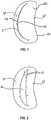
- FIG. 5illustrates an exemplary fixation device 14.
- the fixation device 14is shown coupled to a shaft 12 to form an interventional tool 10.
- the fixation device 14includes a coupling member 19, a pair of opposed proximal elements 16, and a pair of opposed distal elements 18.
- the distal elements 18comprise elongate arms 53, each arm having a proximal end 52 rotatably connected to the coupling member 19 and a free end 54.
- each free end 54defines a curvature about two axes, axis 66 perpendicular to longitudinal axis of arms 53, and axis 67 perpendicular to axis 66 or the longitudinal axis of arms 53.
- Arms 53have engagement surfaces 50. Arms 53 and engagement surfaces 50 are configured to engage about 4-10 mm of tissue, and preferably about 6-8 mm along the longitudinal axis of arms 53. Arms 53 further include a plurality of openings.
- the proximal elements 16are preferably resiliently biased toward the distal elements 18. When the fixation device 14 is in the open position, each proximal element 16 is separated from the engagement surface 50 near the proximal end 52 of arm 53 and slopes toward the engagement surface 50 near the free end 54 with the free end of the proximal element 16 contacting engagement surface 50, as illustrated in Figure 5 .
- Proximal elements 16include a plurality of openings 63 and scalloped side edges 61 to increase their grip on tissue.
- the proximal elements 16optionally include a frictional element or multiple frictional elements to assist in grasping the leaflets.
- the frictional elementsmay comprise barbs 60 having tapering pointed tips extending toward engagement surfaces 50. Any suitable frictional elements may be used, such as prongs, windings, bands, barbs, grooves, channels, bumps, surface roughening, sintering, high-friction pads, coverings, coatings or a combination of these.
- the proximal elements 16may be covered with a fabric or other flexible material.
- fabrics or coveringsare used in combination with barbs or other frictional features, such features will protrude through such fabric or other covering so as to contact any tissue engaged by proximal elements 16.
- the fixation device 14also includes an actuator or actuation mechanism 58.
- the actuation mechanism 58comprises two link members or legs 68, each leg 68 having a first end 70 which is rotatably joined with one of the distal elements 18 at a riveted joint 76 and a second end 72 which is rotatably joined with a stud 74.
- the actuation mechanism 58comprises two legs 68 which are each movably coupled to a base 69. Or, each leg 68 may be individually attached to the stud 74 by a separate rivet or pin.
- the stud 74is joinable with an actuator rod which extends through the shaft 12 and is axially extendable and retractable to move the stud 74 and therefore the legs 68 which rotate the distal elements 18 between closed, open and inverted positions. Immobilization of the stud 74 holds the legs 68 in place and therefore holds the distal elements 18 in a desired position.
- the stud 74may also be locked in place by a locking feature.
- This actuator rod and stud assemblymay be considered a first means for selectively moving the distal elements between a first position in which the distal elements are in a collapsed, low profile configuration for delivery of the device, a second position in which the distal elements are in an expanded configuration for positioning the device relative to the mitral valve, and a third position in which the distal elements are secured in position against a portion of the leaflets adjacent the mitral valve on the ventricular side.
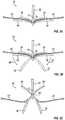
- Figures 6A-6B, 7A-7B , and 8illustrate various possible positions of the fixation device 14 of Figure 5 .
- Figure 6Aillustrates an interventional tool 10 delivered through a catheter 86.
- the catheter 86may take the form of a guide catheter or sheath.
- the interventional tool 10comprises a fixation device 14 coupled to a shaft 12 and the fixation device 14 is shown in the closed position.
- Figure 6Billustrates a device similar to the device of Figure 6A in a larger view.
- the opposed pair of distal elements 18are positioned so that the engagement surfaces 50 face each other.
- Each distal element 18comprises an elongate arm 53 having a cupped or concave shape so that together the arms 53 surround the shaft 12. This provides a low profile for the fixation device 14.
- Figures 7A-7Billustrate the fixation device 14 in the open position.
- the distal elements 18are rotated so that the engagement surfaces 50 face a first direction.
- Such rotation and movement of the distal elements 18 radially outwardcauses rotation of the legs 68 about joints 80 so that the legs 68 are directed slightly outwards.
- the stud 74may be advanced to any desired distance correlating to a desired separation of the distal elements 18.
- engagement surfaces 50are disposed at an acute angle relative to shaft 12, and are preferably at an angle of between 90 and 180 degrees relative to each other.
- the free ends 54 of arms 53may have a span therebetween of about 10-20 mm, usually about 12-18 mm, and preferably about 14-16 mm.
- Proximal elements 16are typically biased outwardly toward arms 53.
- the proximal elements 16may be moved inwardly toward the shaft 12 and held against the shaft 12 with the aid of proximal element lines 90 which can be in the form of sutures, wires, nitinol wire, rods, cables, polymeric lines, or other suitable structures.
- the proximal element lines 90extend through the shaft 302 of the delivery catheter 300 and connect with the proximal elements 16.
- the proximal elements 16are raised and lowered by manipulation of the proximal element lines 90. Once the device is properly positioned and deployed, the proximal element lines can be removed by withdrawing them through the catheter and out the proximal end of the device 10.
- the proximal element lines 90may be considered a second means for selectively moving the proximal elements between a first position in which the proximal elements are in a collapsed, low profile configuration for delivery of the device and a second position in which the proximal elements are in an expanded configuration for engaging a portion of the leaflets adjacent the mitral valve on the atrial side.
- the fixation device 14can engage the tissue which is to be approximated or treated.
- the interventional tool 10is advanced through the mitral valve from the left atrium to the left ventricle.
- the distal elements 18are then deployed by advancing actuator rod relative to shaft 12 to thereby reorient distal elements 18 to be perpendicular to the line of coaptation.
- the entire assemblyis then withdrawn proximally and positioned so that the engagement surfaces 50 contact the ventricular surface of the valve leaflets, thereby engaging the left ventricle side surfaces of the leaflets.
- the proximal elements 16remain on the atrial side of the valve leaflets so that the leaflets lie between the proximal and distal elements.
- the interventional tool 10may be repeatedly manipulated to reposition the fixation device 14 so that the leaflets are properly contacted or grasped at a desired location. Repositioning is achieved with the fixation device in the open position. In some instances, regurgitation may also be checked while the device 14 is in the open position. If regurgitation is not satisfactorily reduced, the device may be repositioned and regurgitation checked again until the desired results are achieved.
- FIG. 8illustrates the fixation device 14 in the inverted position.
- the distal elements 18are further rotated so that the engagement surfaces 50 face outwardly and free ends 54 point distally, with each arm 53 forming an obtuse angle relative to shaft 12.
- the angle between arms 53 when the device is invertedis preferably in the range of about 270 to 360 degrees. Further advancement of the stud 74 further rotates the distal elements 18 around joints 76. This rotation and movement of the distal elements 18 radially outward causes rotation of the legs 68 about joints 80 so that the legs 68 are returned toward their initial position, generally parallel to each other.
- the stud 74may be advanced to any desired distance correlating to a desired inversion of the distal elements 18.
- the span between free ends 54is no more than about 20 mm, usually less than about 16 mm, and preferably about 12-14 mm.
- Barbs 60are angled slightly in the distal direction (away from the free ends of the proximal elements 16), reducing the risk that the barbs will catch on or lacerate tissue as the fixation device is withdrawn.
- the leafletsmay then be captured between the proximal elements 16 and the distal elements 18.
- the proximal elements 16are lowered toward the engagement surfaces 50 by releasing tension from proximal element lines 90, thereby releasing proximal elements 16 so that they are then free to move, in response to the internal spring bias force formed into proximal elements 16, from a constrained, collapsed position to an expanded, deployed position and so that the leaflets are held between the proximal elements 16 and the distal elements 18. If regurgitation is not sufficiently reduced, the proximal elements 16 may be raised and the distal elements 18 adjusted or inverted to reposition the fixation device 14.
- the distal elements 18may be locked to hold the leaflets LF in this position or the fixation device 14 may be returned to or toward a closed position. This is achieved by retraction of the stud 74 proximally relative to coupling member 19 so that the legs 68 of the actuation mechanism 58 apply an upwards force to the distal elements 18 which in turn rotate the distal elements 18 so that the engagement surfaces 50 again face one another.
- the released proximal elements 16which are biased outwardly toward distal elements 18 are concurrently urged inwardly by the distal elements 18.
- the fixation device 14may then be locked to hold the leaflets in this closed position.
- the fixation device 14may then be released from the shaft 12.
- the fixation device 14optionally includes a locking mechanism for locking the device 14 in a particular position, such as an open, closed or inverted position or any position therebetween.
- the locking mechanismmay include a release harness. Applying tension to the release harness may unlock the locking mechanism.
- the lock lines 92engage the release harnesses 108 of the locking mechanism 106 to lock and unlock the locking mechanism 106.
- the lock lines 92extend through the shaft 302 of the delivery catheter 300.
- a handle attached to the proximal end of the shaftis used to manipulate and decouple the fixation device 14.
- fixation devices 14may be found in PCT Publication No. WO 2004/103162 and U.S. Patent Application No. 14/216,787 , the disclosures of both of which are incorporated herein in their entirety.
- fixation device 14Sometimes it can be difficult to capture or retain tissue within fixation device 14 so that fixation device 14 approximates or repairs the tissue as desired.
- Leaflet insertionmay be assessed throughout the process of installing a fixation device 14, but it can be difficult to differentiate good and poor leaflet insertion and retention. For example, when fixation device 14 is used in endovascular or minimally invasive procedures, visualization of the capturing or retention of tissue may be difficult.
- the tissue desired to be captured or retained between proximal elements 16 and distal elements 18may seem to be securely captured or retained when it is actually only partially captured or insecurely captured.
- the free edges FE of leaflet tissue LFmay later disassociate from the fixation device 14 and the fixation device 14 may then not properly coapt, approximate, or repair the tissue.
- imaging methodsmake it possible to visualize when tissue is captured in the fixation device, they may not allow for a viewer to distinguish between securely and insecurely captured tissue. For example, color Doppler echo may show that regurgitation has been reduced, but it may not provide precise specifics on where along the leaflets LF fixation device 14 has captured the tissue, and whether the capturing is secure.
- leaflet LFmay separate from the fixation device 14. This may result in the fixation device 14 being attached to only one of the leaflets LF, or separating from both leaflets LF, and no longer functioning as desired.
- fixation device 14In addition to difficulties arising from the imaging or visualization of the device 14 as it is installed, difficulty in capturing or retaining tissue within fixation device 14 may also result from the nature of tissue desired to be captured or retained. For example, when using fixation device 14 to fix mitral valve leaflets LF to each other to stop or reduce mitral valve regurgitation, the leaflets LF are constantly moving as the heart beats.
- Figures 9 - 12illustrate various embodiments that are intended to help a fixation device 14' capture and retain the free edges FE of leaflets LF during placement of the fixation device 14'.
- these embodimentsinclude the addition of a retaining element 400 positioned on the proximal side of each distal element 18'.
- the retaining element 400combines with frictional elements such as barbs 410 at the lower end of the proximal element 16' to capture the free edge FE of the leaflet upon its initial insertion and help retain it there until the proximal and distal elements are fully deployed.
- the lower end of the proximal element 16'is the end closest to the stud 74'.
- the retaining element 400 and barbs 410are configured to cooperate to allow the free edge FE of the leaflets LF to easily or freely move in a first direction toward the apex 430 formed between each proximal element 16' and the corresponding distal element 18', but at the same time to resist or prevent movement of the free edge FE of the leaflet tissue LF in the opposite direction away from apex 430.
- retaining element 400in cooperation with the barbs 410, help to retain the leaflets LF in the device 14' while the device is being positioned relative to the leaflets LF and before the proximal elements 16' and distal elements 18' are fully deployed.
- the retaining element 400may serve as a passive capture mechanism that retains leaflet tissue LF without needing to be activated.
- the retaining element 400may retain leaflet tissue LF in the device 14' when a length of tissue of about 4-10 mm, and preferably about 6-8 mm, is located along the longitudinal axis of the distal elements 18'.
- a retaining element 400may be located on the distal elements 18', as shown in the illustrated embodiments, or the retaining element 400 may be located on the proximal elements 16', or it may be located on both the distal elements 18' and the proximal elements 16'.
- a retaining element 400may hold a leaflet LF in place without closing the fixation element 18' and gripping element 16'.
- a retaining element 400may be a spring element 402 that retains leaflets LF inserted into the fixation device 14'.
- the spring element 402may help capture or hold any leaflet LF that inserts past a given point along the distal elements 18' which is determined to be sufficient insertion depth.
- the spring element 402is on a distal element 18'.
- Each distal element 18'has a spring element 402 incorporated into or attached to the distal element 18'.
- the spring element 402may be incorporated into or attached to the distal element 18' at a midpoint 414 between a first end 404 of the distal element 18' that attaches to a stud 74' and the free end 406 of the distal element 18'. It may also be incorporated into or attached to the distal element 18' closer to the free end 406 of each distal element 18' or to the first end 404 of each distal element 18'.
- the fixed end 412 of the spring element 402is located between the midpoint 414 and free end 406 of the distal element 18'.
- the spring element 402 of the retaining element 400is elongate and can extend in an elongate fashion along substantially an entire length of the distal element 18' and associated distal engagement surface.
- the retaining element 400can extend in an elongate fashion from a location near or adjacent first end 404 to a location distal a midpoint of the distal engagement surface of the distal element 18' or from a location near or adjacent second end 406 to a location distal a midpoint of the distal engagement surface of the distal element 18'.
- the spring element 402may comprise a low-force leaf spring 408 biased to push the spring element 402 towards the leaflet LF and encourage frictional elements or barbs 410 to be deeply inserted into the leaflet LF, so the leaflet LF remains in a fully seated state until distal elements 18' are further closed.
- barbs 410are orientated at an angle pointing toward apex 430. With barbs 410 oriented in that direction, the leading edge LE of the leaflet tissue LF is allowed to move in a first direction toward apex 430 with little or no restriction or resistance. As the leading edge LE of the leaflet tissue moves toward apex 430, spring element 402 directs or urges the leaflet tissue LF toward and into contact with barbs 410.
- the combination of the retaining element 400 and the barbs 410effectively function as a directional trap that permits the leaflet tissue LF to move in a first direction toward apex 430 with little or no resistance, while restricting or preventing movement of the leaflet tissue LF in a second or opposite direction away from apex 430.
- the leaf spring 408may have one or more lobes or a partial lobe.
- the leaf spring 408may be biased to allow for little to no resistance to a leaflet LF as it inserts. It may have surface features, a pointed edge, or other elements that create resistance to make it difficult for the leaflet LF to retract out. Such surface features may include, for example, dimples, bumps, ridges, or indents.
- the free end 416 of the spring element 402may be configured to curve toward the distal elements 18' (as shown in Figure 9A ) when tissue LF is being trapped, and curve away from the distal element 18' (as shown in Figure 9B ) when tissue LF is being released.
- the free end 416 of the spring element 402may be configured to lie flat against the distal element 18'.
- the retaining element 400helps the fixation device 14 capture tissue when proximal elements 16' are raised and distal elements 18' are still partially open.
- the retaining element 400may be configured to urge the leaflet tissue against the barbs 410 on the proximal elements 16.
- the retaining element 400may be a one-way mechanism that allows tissue to enter but not exit, such as a ratchet or something similar to a ratchet.
- the one-way mechanismshould have a way for the leaflet tissue LF to be permitted to escape.
- the retaining elementcan be designed to allow tissue to exit under certain circumstances, such as when the distal elements 18' are opened to approximately 180°, as shown in Figure 9B , or are opened even further in an inverted position, as shown in Figure 8 . Or, when the proximal elements 16' are raised, the leaflet tissue LF may be released to allow regrasping.
- one method of using a device with a retaining element 400 such as a spring element 402 located near each set of distal elements 18' and proximal elements 16'is to first capture one or both leaflets LF in the spring element 402.
- the spring elementurges the leaflets LF against the barbs 410 at the lower end of the proximal element 16' to capture the free edge FE of the leaflet LF upon its initial insertion and help retain it there until the proximal and distal elements 16, 18 are fully deployed.
- leaflets LFmay be captured based on imaging methods such as color Doppler echo.
- imaging methodssuch as color Doppler echo.
- the proximal elements 16'may be lowered toward the surfaces 50' of the distal elements 18', so that the leaflets LF are held therebetween and the distal elements 18' may be locked to hold the leaflets LF in this position or the fixation device 14' may be returned to or toward a closed position.
- a retaining element 400comprises an arm 417.
- Each distal element 18'has an arm 417 incorporated into or attached to the distal element 18'.
- the arm 417may be incorporated into or attached at a fixed end 415 to the distal element 18' at a midpoint 414 between a first end 404 of the distal element 18' that attaches to a stud 74' and the free end 406 of the distal element 18'. It may also be incorporated into or attached to the distal element 18' closer to the free end 406 of each distal element 18' or to the first end 404 of each distal element 18'.
- the fixed end 415 of the arm 417is located between the midpoint 414 and free end 406 of the distal element 18'.
- the arm 417has a projection or projections 418 of a suitable shape and size to assist in retaining the leaflets LF in position.
- These projections 418may have sharp tips located opposite to the arm 417, or sharp edges between their tips and the arm 417. They may comprise barbs having tapering pointed tips, scalloped edges, prongs, windings, bands, grooves, channels, bumps, surface roughening, sintering, high-friction pads, coverings, coatings or a combination of these. As shown in Figure 10 , these projections may be oriented away from the surface 50' and angled away from the free ends 406 of the distal element 18'. They may also orient toward the free ends 406, or be perpendicular to the surface 50'.
- the projectionsmay flex or collapse toward the distal clement 18' when the fixation device 14' is closed and flex out to a fixed angle when the fixation device 14' is open.
- the projections 418may bias toward a fixed angle from the engagement surfaces 50', but may be pushed flat against the distal element 18' when the distal elements 18' close around the shaft 12.
- the fixation deviceshould be configured with enough space between the proximal elements 16' and the distal elements 18' for a leaflet LF to be easily inserted past the projections 418 on the distal elements 18'.
- the chordal tethered leaflets LFmay be tensioned lightly upon the fixation device 14' just prior to closing the distal elements 18' and proximal elements 16'. They may also be securely affixed to the device 14' prior to closing the distal elements 18' and proximal elements 16'.
- the arm 417may be a flexible leaf-spring that pivots at a fixed end 415 and is positioned between the proximal element 16' and distal elements 18'. It may also include a system of projections 418 angled to allow entry of the tissue between the distal element 18' and proximal element 16', but to prevent retraction of the tissue LF. As shown, the projection 418 and leaf spring 417 may be combined in the same structure.
- the arm 417 of the retaining element 400is elongate and can extend in an elongate fashion along substantially an entire length of the distal element 18' and associated distal engagement surface.
- the retaining element 400can extend in an elongate fashion from a location near or adjacent first end 404 to a location distal a midpoint of the distal engagement surface of the distal element 18' or from a location near or adjacent second end 406 to a location distal a midpoint of the distal engagement surface of the distal element 18'.
- the retaining element 400may comprise one or more protrusions 420.
- One or more protrusions 420may be positioned close to the hinge point of the distal elements 18' on the engagement surface 50'.
- the protrusion 420may reduce leaflet detachment upon deployment of the fixation device 14' by directing or urging the leaflet LF into contact with the gripping surfaces or barbs 410 located on the opposing proximal element 16'.
- the protruding feature 420may be located near a midpoint 414 between a first end 404 of the distal element 18' that attaches to a stud 74' and the free end 406 of the distal element 18'. It may also be incorporated into or attached to the distal element 18' closer to the free end 406 of each distal element 18' or to the first end 404 of each distal element 18'.
- a protruding feature 420may be a rigid piece of material that is affixed to the engagement surface 50' of distal elements 18' and may be atraumatic to aid with directing or urging the leaflet LF while causing minimal damage to the leaflet LF, such as not penetrating or puncturing the leaflet LF.
- the protruding featuremay be comprised of any biocompatible material or materials, such as a polymer, nitinol, or other alloys, or bioabsorbable materials.
- the protruding feature 420 of the distal elements 18'may passively engage the leaflet tissue LF when leaflet tissue LF is sufficiently inserted into the device 14'. Or, the protruding feature 420 may be configured to help engage leaflet tissue and secure it into position when the proximal elements 16' are lowered and also secure the leaflet tissue LF. The protruding feature 420 may help entrap tissue between the protruding feature 420 and the gripping surfaces of the proximal elements 16'. The feature 420 may urge the tissue LF against the barbs 410.
- the protruding feature 420is illustrated as including a generally curved or domed outer surface, it will be understood that various other surface orientations are appropriate while maintaining the atraumatic nature and ability to aid with directing or urging the leaflet LF.
- the protruding feature 420can have a curved surface that is symmetric or asymmetric in (i) a direction from first end 404 towards the second end 406. (ii) a direction cross-wise, transverse, or oblique to the direction from first end 404 towards the second end 406, or (iii) both.
- the protruding feature 420can be symmetric in at least one axis, at least two axes, or in all three axes.
- the protruding feature 420can be asymmetric in at least one axis, at least two axes, or in all three axes.
- the retaining element 400may comprise a hinge 422 that is attached to the surface 50' of the distal elements 18'.
- the hinge 422connects to an arm 424 that can swing toward and away from the distal element 18'.
- the arm 424may bias toward the first end 404 of each distal element 18'.
- the arm 424may be capable of laying parallel to or flat against the surface 50' while being oriented toward the first end 404 of the distal element 18'. It also may be capable of laying parallel to or flat against the surface 50' while being oriented toward the free end 406 of the distal element 18', and therefore capable of rotating 180°.
- the hinge 422may restrict the movement of the arm 424 so that it can, for example, only lie parallel to the surface 50' while being oriented toward the first end 404 of the distal element 18' and be rotated about 90°, so that the angle formed between the arm 424 and the portion of the distal element 18' below the hinge 422 can be no greater than 90°.
- the hinge 422may also be a pivoting element.
- arms 424 on the distal element 18'there may also be multiple arms 424 on the distal element 18'. For example, there may be two arms, each located the same distance between the ends 404 and 406, and positioned next to each other on the engagement surface 50'. If there are multiple retaining elements 400, such as multiple arms 424 or multiple spring elements 402, they may be configured to be positioned on either side of the barbs 410 on the proximal element. Retaining element or elements 400 may also be positioned to be located between barbs 410 on the proximal element 16', if there are multiple barbs 410 on the proximal element 16'.
- the arm 424 of the retaining element 400is elongate and can extend in an elongate fashion along substantially an entire length of the distal element 18' and associated distal engagement surface.
- the retaining element 400, and associated arm 424can extend in an elongate fashion from a location near or adjacent first end 404 to a location distal a midpoint of the distal engagement surface of the distal element 18' or from a location near or adjacent second end 406 to a location distal a midpoint of the distal engagement surface of the distal element 18'.
- the distal elements 18may be covered with a fabric or other flexible material.
- fabrics or coveringsare used in combination with projections 418, such features will protrude through such fabric or other covering so as to contact the leaflet tissue LF.
- the bias, angle, and direction of a retaining element 400may allow the leaflet to fall or slide deeper towards the stud 74' without much resistance but may restrict the ability of the leaflet LF to move back out. By permitting the leaflet LF to easily enter but not permitting it to easily be removed from the fixation device 14', this may help entrap the leaflet LF in a fully inserted state.
- the retaining element 400is a passive element.
- retaining element 400may also include an active element such that, when a piece of leaflet tissue LF proceeds beyond or next to a portion of the retaining element 400, the retaining element 400 may automatically spring or deploy in such a way as to retain tissue LF in place.
- a fixation device 14 or 14'may comprise a mechanical or physical sensor or some visual indicator of when a leaflet is properly inserted into the device prior to closing the distal elements 18' and deployment of the fixation device 14 or 14'.
- a tactile sensormay be embedded near the first end 404 of each distal element. Each tactile sensor may provide a signal or indication when the leaflet LF touches the sensor, and the sensor may be located so that the leaflet LF will be unable or unlikely to touch the sensor unless the leaflet is adequately captured.
- Yet another mechanism for enhancing the placement and retention of the leaflet tissue LF in the fixation device 14 or 14'is to facilitate actuation of each proximal element 16 or 16' and each distal element 18 or 18' independent from one another.
- the proximal elements 16 or 16' for both leaflets LFare activated simultaneously, and the distal elements 18 or 18' for each leaflet LF are also activated simultaneously, it can be hard to capture both leaflets, because it is necessary to capture both at the same time.
- the fixation device 14 or 14'is not able to grasp one leaflet first and then the other.
- fixation device 14 or 14'may not fully seat the leaflets between each distal fixation element 18 or 18' and proximal gripping element 16 or 16'.
- each proximal element 16 or 16' and/or each distal element 18 or 18'may be activated independently from each other.
- these devicescan be used in a variety of therapeutic procedures, including endovascular, minimally-invasive, and open surgical procedures, and can be used in various anatomical regions, including abdominal, thoracic, cardiovascular, intestinal, digestive, respiratory, and urinary systems, and other systems and tissues.
- the inventionprovides devices, systems, and methods that may more successfully approximate and repair tissue by improving the capture of tissue into the devices.
Landscapes
- Health & Medical Sciences (AREA)
- Life Sciences & Earth Sciences (AREA)
- Surgery (AREA)
- Biomedical Technology (AREA)
- General Health & Medical Sciences (AREA)
- Engineering & Computer Science (AREA)
- Heart & Thoracic Surgery (AREA)
- Veterinary Medicine (AREA)
- Public Health (AREA)
- Animal Behavior & Ethology (AREA)
- Medical Informatics (AREA)
- Nuclear Medicine, Radiotherapy & Molecular Imaging (AREA)
- Molecular Biology (AREA)
- Vascular Medicine (AREA)
- Reproductive Health (AREA)
- Cardiology (AREA)
- Oral & Maxillofacial Surgery (AREA)
- Transplantation (AREA)
- Prostheses (AREA)
- Surgical Instruments (AREA)
Abstract
Description
- This application claims the benefit of and priority to
U.S. Application No. 14/577,852, filed on December 19, 2014 - The present invention relates generally to medical methods, devices, and systems. In particular, the present invention relates to methods, devices, and systems for the endovascular, percutaneous, or minimally invasive surgical treatment of bodily tissues, such as tissue approximation or valve repair. More particularly, the present invention relates to repairing heart valves and venous valves, and devices and methods for removing or disabling mitral valve repair components through minimally invasive procedures.
- Surgical repair of bodily tissues often involves tissue approximation and fastening of such tissues in the approximated arrangement. When repairing valves, tissue approximation includes coapting the leaflets of the valves in a therapeutic arrangement which may then be maintained by fastening or fixing the leaflets. Such coaptation can be used to treat regurgitation which most commonly occurs in the mitral valve.
- Mitral valve regurgitation is characterized by retrograde flow from the left ventricle of a heart through an incompetent mitral valve into the left atrium. During a normal cycle of heart contraction (systole), the mitral valve acts as a check valve to prevent oxygenated blood from flowing back into the left atrium. In this way, oxygenated blood is pumped into the aorta through the aortic valve. Mitral valve regurgitation can significantly decrease the pumping efficiency of the heart, placing the patient at risk of severe, progressive heart failure.
- Mitral valve regurgitation can result from a number of different mechanical defects in the mitral valve or the left ventricular wall. The valve leaflets, the valve chordae which connect the leaflets to the papillary muscles, the papillary muscles themselves, or the left ventricular wall may be damaged or otherwise dysfunctional. Commonly, the valve annulus may be damaged, dilated, or weakened, limiting the ability of the mitral valve to close adequately against the high pressures of the left ventricle.
- The most common treatments for mitral valve regurgitation rely on valve replacement or repair including leaflet and annulus remodeling, the latter generally referred to as valve annuloplasty. One technique for mitral valve repair which relies on suturing adjacent segments of the opposed valve leaflets together is referred to as the "bow-tie" or "edge-to-edge" technique. While all these techniques can be effective, they usually rely on open heart surgery where the patient's chest is opened, typically via a sternotomy, and the patient placed on cardiopulmonary bypass. The need to both open the chest and place the patient on bypass is traumatic and has associated high mortality and morbidity.
- In some patients, a fixation device can be installed into the heart using minimally invasive techniques. The fixation device can hold the adjacent segments of the opposed valve leaflets together and may reduce mitral valve regurgitation. One such device used to clip the anterior and posterior leaflets of the mitral valve together is the MitraClip® fixation device, sold by Abbott Vascular, Santa Clara, California, USA.
- Many techniques exist for approximating and repairing tissues and organs at treatment sites. For example, minimally invasive and percutaneous techniques for coapting and modifying mitral valve leaflets to treat mitral valve regurgitation are described in
PCT Publication Nos. WO 98/35638 WO 99/00059 WO 99/01377 WO 00/03759 WO 2000/060995 WO 2004/103162 - Mitral valve annuloplasty is described in the following publications:Bach and Boiling (1996) Am. J. Cardiol. 78:966-969;Kameda et al. (1996) Ann. Thorac. Surg. 61:1829-1832;Bach and Boiling (1995) Am. Heart J. 129:1165-1170; and Boiling et al. (1995) 109:676-683. Linear segmental annuloplasty for mitral valve repair is described inRicchi et al. (1997) Ann. Thorac. Surg. 63:1805-1806. Tricuspid valve annuloplasty is described inMcCarthy and Cosgrove (1997) Ann. Thorac. Surg. 64:267-268;Tager et al. (1998) Am. J. Cardiol. 81:1013-1016; andAbe et al. (1989) Ann. Thorac. Surg. 48:670-676.
- Percutaneous transluminal cardiac repair procedures are described inPark et al. (1978) Circulation 58:600-608;Uchida et al. (1991) Am. Heart J. 121: 1221-1224; andAli Khan et al. (1991) Cathet. Cardiovasc. Diagn. 23:257-262. Endovascular cardiac valve replacement is described in
U.S. Patent Nos. 5,840,081 ;5,411,552 ;5,554,185 ;5,332,402 ;4,994,077 ; and4,056,854 .U.S. Patent No. 3,671,979 describes a catheter for temporary placement of an artificial heart valve. - Other percutaneous and endovascular cardiac repair procedures are described in
U.S. Patent Nos. 4,917,089 ;4,484,579 ; and3,874,338 ; andPCT Publication No. WO 91/01689 - The present disclosure describes devices intended for intravascular delivery and for use in treating mitral valve defects in human patients. The mitral valve of a human heart has an atrial side, a ventricular side, an anterior leaflet, a posterior leaflet, and an opening between the leaflets.
- In one embodiment, the device can include a body, a pair of proximal elements, and a pair of distal elements. Each proximal element is coupled at a first end to the body on opposite sides of the body, and has a free second end. Each proximal element has a proximal engagement surface between its first and second ends. Each proximal engagement surface is configured to approximate and engage a portion of the leaflets adjacent the mitral valve on the atrial side. Each proximal engagement surface also has a proximal retaining element configured to permit tissue to move toward the first end of the proximal element and to resist movement of the tissue away from the first end of the proximal element.
- Each distal element is pivotally coupled at a first end to the body on opposite sides of the body, and has a free second end. Each distal element has a distal engagement surface between its first and second ends. Each distal engagement surface is configured to approximate and engage a portion of the leaflets adjacent the mitral valve on the ventricular side.
- A first one of the proximal elements cooperates with a first one of the distal elements to form a space for receiving a portion of the anterior leaflet therebetween. A second one of the proximal elements cooperates with a second one of the distal elements to form a space for receiving a portion of the posterior leaflet therebetween. Each such space has an open end and a closed end, and the closed end forms an apex.
- The device includes an actuator for selectively moving the distal elements between a first position in which the distal elements are in a collapsed, low profile configuration for delivery of the device, a second position in which the distal elements are in an expanded configuration for positioning the device relative to the mitral valve, and a third position in which the distal elements are secured in position against a portion of the leaflets adjacent the mitral valve on the ventricular side.
- The device also includes an actuator for selectively moving the proximal elements between a first position in which the proximal elements are in a collapsed, low profile configuration for delivery of the device and a second position in which the proximal elements are in an expanded configuration for engaging a portion of the leaflets adjacent the mitral valve on the atrial side.
- Each distal element can also include a distal retaining element positioned along the distal engagement surface. Each distal retaining element is configured to cooperate with a corresponding proximal retaining element to capture a free edge of the mitral valve leaflet as the device is positioned relative to the mitral valve. Each retaining element can be configured to cooperate with a frictional element to allow a leading free edge of the leaflets to move in a first direction toward the body with little or no resistance or restriction and to resist or prevent movement of the free edge of the leaflets in an opposite direction away from the body.
- These and other objects and features of the present disclosure will become more fully apparent from the following description and appended claims, or may be learned by the practice of the embodiments of the invention as set forth hereinafter.
- To further clarify the above and other advantages and features of the present disclosure, a more particular description of the invention will be rendered by reference to specific embodiments thereof which are illustrated in the appended drawings. It is appreciated that these drawings depict only illustrated embodiments of the invention and are therefore not to be considered limiting of its scope. Embodiments of the invention will be described and explained with additional specificity and detail through the use of the accompanying drawings in which:
Figure 1 illustrates free edges of leaflets of the mitral valve in normal coaptation, andFigure 2 illustrates the free edges in regurgitative coaptation.Figures 3A-3C illustrate grasping of the leaflets with a fixation device, inversion of the distal elements of the fixation device and removal of the fixation device, respectively.Figure 4 illustrates the fixation device in a desired orientation relative to the leaflets.Figure 5 illustrates an exemplary fixation device coupled to a shaft.Figures 6A-6B, 7A-7B , and8 illustrate a fixation device in various possible positions during introduction and placement of the device within the body to perform a therapeutic procedure.Figures 9A-9B illustrate a fixation device embodiment with a leaf spring.Figure 10 illustrates a close-up of a portion of another embodiment of a fixation device.Figure 11A illustrates a close-up of a portion of another embodiment of a fixation device.Figures 11B and 11C each illustrate a close-up cross-sectional side view of a portion of another embodiment of a fixation device.Figures 11D and 11E each illustrate a close-up cross-sectional transverse view of a portion of another embodiment of a fixation device.Figure 12 illustrates a close-up of a portion of another embodiment of a fixation device.- As shown in
Figure 1 , the mitral valve (MV) comprises a pair of leaflets (LF) having free edges (FE) which, in patients with normal heart structure and function, meet evenly to close along a line of coaptation (C). The leaflets (LF) attach to the surrounding heart structure along an annular region called the annulus (AN). The free edges (FE) of the leaflets (LF) are secured to the lower portions of the left ventricle LV through chordae tendinae (or "chordae"). - As the left ventricle of a heart contracts (which is called "systole"), blood flow from the left ventricle to the left atrium through the mitral valve (MV) (called "mitral regurgitation") is usually prevented by the mitral valve.
- Regurgitation occurs when the valve leaflets do not close properly and allow leakage from the left ventricle into the left atrium. A number of heart structural defects can cause mitral regurgitation.
Figure 2 shows a mitral valve with a defect causing regurgitation through a gap (G). - Several methods for repairing or replacing a defective mitral valve exist. Some defects in the mitral valve can be treated through intravascular procedures, where interventional tools and devices are introduced and removed from the heart through the blood vessels. One method of repairing certain mitral valve defects includes intravascular delivery of a fixation device to hold portions of the mitral valve tissues in a certain position. One or more interventional catheters may be used to deliver a fixation device to the mitral valve and install it there as an implant to treat mitral regurgitation.
Figure 3A illustrates a schematic of aninterventional tool 10 with adelivery shaft 12 and afixation device 14. Thetool 10 has approached the mitral valve MV from the atrial side and grasped the leaflets LF.- The
fixation device 14 is releasably attached to theshaft 12 of theinterventional tool 10 at the distal end of theshaft 12. In this application, when describing devices, "proximal" means the direction toward the end of the device to be manipulated by the user outside the patient's body, and "distal" means the direction toward the working end of the device that is positioned at the treatment site and away from the user. When describing the mitral valve, proximal means the atrial side of the leaflets and distal means the ventricular side of the leaflets. - The
fixation device 14 comprisesproximal elements 16 anddistal elements 18 which protrude radially outward and are positionable on opposite sides of the leaflets LF as shown so as to capture or retain the leaflets therebetween. Thefixation device 14 is coupleable to theshaft 12 by acoupling mechanism 17. Figure 3B illustrates that thedistal elements 18 may be moved in the direction ofarrows 40 to an inverted position. Theproximal elements 16 may be raised as shown inFigure 3C . In the inverted position, thedevice 14 may be repositioned and then be reverted to a grasping position against the leaflets as inFigure 3A . Or, thefixation device 14 may be withdrawn (indicated by arrow 42) from the leaflets as shown inFigure 3C . Such inversion reduces trauma to the leaflets and minimizes any entanglement of the device with surrounding tissues.Figure 4 illustrates thefixation device 14 in a desired orientation in relation to the leaflets LF. The mitral valve MV is viewed from the atrial side, so theproximal elements 16 are shown in solid line and thedistal elements 18 are shown in dashed line. The proximal anddistal elements fixation device 14 holds the leaflets LF in position between theelements Figure 4 .- Once the leaflets are coapted in the desired arrangement, the
fixation device 14 is detached from theshaft 12 and left behind as an implant. Figure 5 illustrates anexemplary fixation device 14. Thefixation device 14 is shown coupled to ashaft 12 to form aninterventional tool 10. Thefixation device 14 includes acoupling member 19, a pair of opposedproximal elements 16, and a pair of opposeddistal elements 18.- The
distal elements 18 compriseelongate arms 53, each arm having aproximal end 52 rotatably connected to thecoupling member 19 and afree end 54. Preferably, eachfree end 54 defines a curvature about two axes,axis 66 perpendicular to longitudinal axis ofarms 53, andaxis 67 perpendicular toaxis 66 or the longitudinal axis ofarms 53. Arms 53 have engagement surfaces 50.Arms 53 andengagement surfaces 50 are configured to engage about 4-10 mm of tissue, and preferably about 6-8 mm along the longitudinal axis ofarms 53.Arms 53 further include a plurality of openings.- The
proximal elements 16 are preferably resiliently biased toward thedistal elements 18. When thefixation device 14 is in the open position, eachproximal element 16 is separated from theengagement surface 50 near theproximal end 52 ofarm 53 and slopes toward theengagement surface 50 near thefree end 54 with the free end of theproximal element 16 contactingengagement surface 50, as illustrated inFigure 5 . Proximal elements 16 include a plurality ofopenings 63 and scalloped side edges 61 to increase their grip on tissue. Theproximal elements 16 optionally include a frictional element or multiple frictional elements to assist in grasping the leaflets. The frictional elements may comprisebarbs 60 having tapering pointed tips extending toward engagement surfaces 50. Any suitable frictional elements may be used, such as prongs, windings, bands, barbs, grooves, channels, bumps, surface roughening, sintering, high-friction pads, coverings, coatings or a combination of these.- The
proximal elements 16 may be covered with a fabric or other flexible material. Preferably, when fabrics or coverings are used in combination with barbs or other frictional features, such features will protrude through such fabric or other covering so as to contact any tissue engaged byproximal elements 16. - The
fixation device 14 also includes an actuator oractuation mechanism 58. Theactuation mechanism 58 comprises two link members orlegs 68, eachleg 68 having afirst end 70 which is rotatably joined with one of thedistal elements 18 at a riveted joint 76 and asecond end 72 which is rotatably joined with astud 74. Theactuation mechanism 58 comprises twolegs 68 which are each movably coupled to abase 69. Or, eachleg 68 may be individually attached to thestud 74 by a separate rivet or pin. Thestud 74 is joinable with an actuator rod which extends through theshaft 12 and is axially extendable and retractable to move thestud 74 and therefore thelegs 68 which rotate thedistal elements 18 between closed, open and inverted positions. Immobilization of thestud 74 holds thelegs 68 in place and therefore holds thedistal elements 18 in a desired position. Thestud 74 may also be locked in place by a locking feature. This actuator rod and stud assembly may be considered a first means for selectively moving the distal elements between a first position in which the distal elements are in a collapsed, low profile configuration for delivery of the device, a second position in which the distal elements are in an expanded configuration for positioning the device relative to the mitral valve, and a third position in which the distal elements are secured in position against a portion of the leaflets adjacent the mitral valve on the ventricular side. Figures 6A-6B, 7A-7B , and8 illustrate various possible positions of thefixation device 14 ofFigure 5 .Figure 6A illustrates aninterventional tool 10 delivered through acatheter 86. Thecatheter 86 may take the form of a guide catheter or sheath. Theinterventional tool 10 comprises afixation device 14 coupled to ashaft 12 and thefixation device 14 is shown in the closed position.Figure 6B illustrates a device similar to the device ofFigure 6A in a larger view. In the closed position, the opposed pair ofdistal elements 18 are positioned so that the engagement surfaces 50 face each other. Eachdistal element 18 comprises anelongate arm 53 having a cupped or concave shape so that together thearms 53 surround theshaft 12. This provides a low profile for thefixation device 14.Figures 7A-7B illustrate thefixation device 14 in the open position. In the open position, thedistal elements 18 are rotated so that the engagement surfaces 50 face a first direction. Distal advancement of the actuator rod relative toshaft 12, and thus distal advancement of thestud 74 relative to couplingmember 19, applies force to thedistal elements 18 which begin to rotate around joints 76. Such rotation and movement of thedistal elements 18 radially outward causes rotation of thelegs 68 aboutjoints 80 so that thelegs 68 are directed slightly outwards. Thestud 74 may be advanced to any desired distance correlating to a desired separation of thedistal elements 18. In the open position, engagement surfaces 50 are disposed at an acute angle relative toshaft 12, and are preferably at an angle of between 90 and 180 degrees relative to each other. In the open position, the free ends 54 ofarms 53 may have a span therebetween of about 10-20 mm, usually about 12-18 mm, and preferably about 14-16 mm.Proximal elements 16 are typically biased outwardly towardarms 53. Theproximal elements 16 may be moved inwardly toward theshaft 12 and held against theshaft 12 with the aid ofproximal element lines 90 which can be in the form of sutures, wires, nitinol wire, rods, cables, polymeric lines, or other suitable structures. Theproximal element lines 90 extend through the shaft 302 of the delivery catheter 300 and connect with theproximal elements 16. Theproximal elements 16 are raised and lowered by manipulation of the proximal element lines 90. Once the device is properly positioned and deployed, the proximal element lines can be removed by withdrawing them through the catheter and out the proximal end of thedevice 10. The proximal element lines 90 may be considered a second means for selectively moving the proximal elements between a first position in which the proximal elements are in a collapsed, low profile configuration for delivery of the device and a second position in which the proximal elements are in an expanded configuration for engaging a portion of the leaflets adjacent the mitral valve on the atrial side.- In the open position, the
fixation device 14 can engage the tissue which is to be approximated or treated. Theinterventional tool 10 is advanced through the mitral valve from the left atrium to the left ventricle. Thedistal elements 18 are then deployed by advancing actuator rod relative toshaft 12 to thereby reorientdistal elements 18 to be perpendicular to the line of coaptation. The entire assembly is then withdrawn proximally and positioned so that the engagement surfaces 50 contact the ventricular surface of the valve leaflets, thereby engaging the left ventricle side surfaces of the leaflets. Theproximal elements 16 remain on the atrial side of the valve leaflets so that the leaflets lie between the proximal and distal elements. Theinterventional tool 10 may be repeatedly manipulated to reposition thefixation device 14 so that the leaflets are properly contacted or grasped at a desired location. Repositioning is achieved with the fixation device in the open position. In some instances, regurgitation may also be checked while thedevice 14 is in the open position. If regurgitation is not satisfactorily reduced, the device may be repositioned and regurgitation checked again until the desired results are achieved. - It may also be desired to invert
distal elements 18 of thefixation device 14 to aid in repositioning or removal of thefixation device 14.Figure 8 illustrates thefixation device 14 in the inverted position. By further advancement of actuator rod relative toshaft 12, and thusstud 74 relative to couplingmember 19, thedistal elements 18 are further rotated so that the engagement surfaces 50 face outwardly and free ends 54 point distally, with eacharm 53 forming an obtuse angle relative toshaft 12. - The angle between
arms 53 when the device is inverted is preferably in the range of about 270 to 360 degrees. Further advancement of thestud 74 further rotates thedistal elements 18 around joints 76. This rotation and movement of thedistal elements 18 radially outward causes rotation of thelegs 68 aboutjoints 80 so that thelegs 68 are returned toward their initial position, generally parallel to each other. Thestud 74 may be advanced to any desired distance correlating to a desired inversion of thedistal elements 18. Preferably, in the fully inverted position, the span between free ends 54 is no more than about 20 mm, usually less than about 16 mm, and preferably about 12-14 mm.Barbs 60 are angled slightly in the distal direction (away from the free ends of the proximal elements 16), reducing the risk that the barbs will catch on or lacerate tissue as the fixation device is withdrawn. - Once the
distal elements 18 of thefixation device 14 have been positioned in a desired location against the left ventricle side surfaces of the valve leaflets, the leaflets may then be captured between theproximal elements 16 and thedistal elements 18. Theproximal elements 16 are lowered toward the engagement surfaces 50 by releasing tension from proximal element lines 90, thereby releasingproximal elements 16 so that they are then free to move, in response to the internal spring bias force formed intoproximal elements 16, from a constrained, collapsed position to an expanded, deployed position and so that the leaflets are held between theproximal elements 16 and thedistal elements 18. If regurgitation is not sufficiently reduced, theproximal elements 16 may be raised and thedistal elements 18 adjusted or inverted to reposition thefixation device 14. - After the leaflets have been captured between the proximal and
distal elements distal elements 18 may be locked to hold the leaflets LF in this position or thefixation device 14 may be returned to or toward a closed position. This is achieved by retraction of thestud 74 proximally relative to couplingmember 19 so that thelegs 68 of theactuation mechanism 58 apply an upwards force to thedistal elements 18 which in turn rotate thedistal elements 18 so that the engagement surfaces 50 again face one another. The releasedproximal elements 16 which are biased outwardly towarddistal elements 18 are concurrently urged inwardly by thedistal elements 18. Thefixation device 14 may then be locked to hold the leaflets in this closed position. Thefixation device 14 may then be released from theshaft 12. - The
fixation device 14 optionally includes a locking mechanism for locking thedevice 14 in a particular position, such as an open, closed or inverted position or any position therebetween. - The locking mechanism may include a release harness. Applying tension to the release harness may unlock the locking mechanism.
- The lock lines 92 engage the release harnesses 108 of the locking mechanism 106 to lock and unlock the locking mechanism 106. The lock lines 92 extend through the shaft 302 of the delivery catheter 300. A handle attached to the proximal end of the shaft is used to manipulate and decouple the
fixation device 14. - Additional disclosure regarding
such fixation devices 14 may be found inPCT Publication No. WO 2004/103162 andU.S. Patent Application No. 14/216,787 , the disclosures of both of which are incorporated herein in their entirety. - Sometimes it can be difficult to capture or retain tissue within
fixation device 14 so thatfixation device 14 approximates or repairs the tissue as desired. Leaflet insertion may be assessed throughout the process of installing afixation device 14, but it can be difficult to differentiate good and poor leaflet insertion and retention. For example, whenfixation device 14 is used in endovascular or minimally invasive procedures, visualization of the capturing or retention of tissue may be difficult. - At times during the process of installing a
fixation device 14, the tissue desired to be captured or retained betweenproximal elements 16 anddistal elements 18 may seem to be securely captured or retained when it is actually only partially captured or insecurely captured. As a result, the free edges FE of leaflet tissue LF may later disassociate from thefixation device 14 and thefixation device 14 may then not properly coapt, approximate, or repair the tissue. Even if imaging methods make it possible to visualize when tissue is captured in the fixation device, they may not allow for a viewer to distinguish between securely and insecurely captured tissue. For example, color Doppler echo may show that regurgitation has been reduced, but it may not provide precise specifics on where along the leafletsLF fixation device 14 has captured the tissue, and whether the capturing is secure. - If a leaflet is poorly grasped between
proximal elements 16 anddistal elements 18, eventually that leaflet LF may separate from thefixation device 14. This may result in thefixation device 14 being attached to only one of the leaflets LF, or separating from both leaflets LF, and no longer functioning as desired. - In addition to difficulties arising from the imaging or visualization of the
device 14 as it is installed, difficulty in capturing or retaining tissue withinfixation device 14 may also result from the nature of tissue desired to be captured or retained. For example, when usingfixation device 14 to fix mitral valve leaflets LF to each other to stop or reduce mitral valve regurgitation, the leaflets LF are constantly moving as the heart beats. Figures 9 - 12 illustrate various embodiments that are intended to help a fixation device 14' capture and retain the free edges FE of leaflets LF during placement of the fixation device 14'. To do so, these embodiments include the addition of a retainingelement 400 positioned on the proximal side of each distal element 18'. The retainingelement 400 combines with frictional elements such asbarbs 410 at the lower end of the proximal element 16' to capture the free edge FE of the leaflet upon its initial insertion and help retain it there until the proximal and distal elements are fully deployed. The lower end of the proximal element 16' is the end closest to the stud 74'.- The retaining
element 400 andbarbs 410 are configured to cooperate to allow the free edge FE of the leaflets LF to easily or freely move in a first direction toward the apex 430 formed between each proximal element 16' and the corresponding distal element 18', but at the same time to resist or prevent movement of the free edge FE of the leaflet tissue LF in the opposite direction away fromapex 430. In this way, retainingelement 400, in cooperation with thebarbs 410, help to retain the leaflets LF in the device 14' while the device is being positioned relative to the leaflets LF and before the proximal elements 16' and distal elements 18' are fully deployed. - The retaining
element 400 may serve as a passive capture mechanism that retains leaflet tissue LF without needing to be activated. For example, the retainingelement 400 may retain leaflet tissue LF in the device 14' when a length of tissue of about 4-10 mm, and preferably about 6-8 mm, is located along the longitudinal axis of the distal elements 18'. A retainingelement 400 may be located on the distal elements 18', as shown in the illustrated embodiments, or the retainingelement 400 may be located on the proximal elements 16', or it may be located on both the distal elements 18' and the proximal elements 16'. A retainingelement 400 may hold a leaflet LF in place without closing the fixation element 18' and gripping element 16'. - As shown in
Figures 9A-9B , in one embodiment, a retainingelement 400 may be aspring element 402 that retains leaflets LF inserted into the fixation device 14'. Thespring element 402 may help capture or hold any leaflet LF that inserts past a given point along the distal elements 18' which is determined to be sufficient insertion depth. - Referring again to
Figures 9A-B , thespring element 402 is on a distal element 18'. Each distal element 18' has aspring element 402 incorporated into or attached to the distal element 18'. Thespring element 402 may be incorporated into or attached to the distal element 18' at amidpoint 414 between afirst end 404 of the distal element 18' that attaches to a stud 74' and thefree end 406 of the distal element 18'. It may also be incorporated into or attached to the distal element 18' closer to thefree end 406 of each distal element 18' or to thefirst end 404 of each distal element 18'. As shown inFigures 9A-B , thefixed end 412 of thespring element 402 is located between themidpoint 414 andfree end 406 of the distal element 18'. In addition, thespring element 402 of the retainingelement 400 is elongate and can extend in an elongate fashion along substantially an entire length of the distal element 18' and associated distal engagement surface. Alternatively, the retainingelement 400 can extend in an elongate fashion from a location near or adjacentfirst end 404 to a location distal a midpoint of the distal engagement surface of the distal element 18' or from a location near or adjacentsecond end 406 to a location distal a midpoint of the distal engagement surface of the distal element 18'. - The
spring element 402 may comprise a low-force leaf spring 408 biased to push thespring element 402 towards the leaflet LF and encourage frictional elements orbarbs 410 to be deeply inserted into the leaflet LF, so the leaflet LF remains in a fully seated state until distal elements 18' are further closed. As illustrated,barbs 410 are orientated at an angle pointing towardapex 430. Withbarbs 410 oriented in that direction, the leading edge LE of the leaflet tissue LF is allowed to move in a first direction towardapex 430 with little or no restriction or resistance. As the leading edge LE of the leaflet tissue moves towardapex 430,spring element 402 directs or urges the leaflet tissue LF toward and into contact withbarbs 410. Once the leaflet tissue LF comes into contact with and engages thebarbs 410, the angled orientation of thebarbs 410causes barbs 410 to penetrate into the leaflet tissue LF and then restricts or prevents movement of the leaflet tissue LF in the opposite direction away fromapex 430. Thus, the combination of the retainingelement 400 and thebarbs 410 effectively function as a directional trap that permits the leaflet tissue LF to move in a first direction towardapex 430 with little or no resistance, while restricting or preventing movement of the leaflet tissue LF in a second or opposite direction away fromapex 430. - The
leaf spring 408 may have one or more lobes or a partial lobe. Theleaf spring 408 may be biased to allow for little to no resistance to a leaflet LF as it inserts. It may have surface features, a pointed edge, or other elements that create resistance to make it difficult for the leaflet LF to retract out. Such surface features may include, for example, dimples, bumps, ridges, or indents. - For example, as shown in
Figure 9A-B , thefree end 416 of thespring element 402 may be configured to curve toward the distal elements 18' (as shown inFigure 9A ) when tissue LF is being trapped, and curve away from the distal element 18' (as shown inFigure 9B ) when tissue LF is being released. When the leaflet is entrapped between the distal elements 18' and the proximal elements 16', thefree end 416 of thespring element 402 may be configured to lie flat against the distal element 18'. - The retaining
element 400 helps thefixation device 14 capture tissue when proximal elements 16' are raised and distal elements 18' are still partially open. The retainingelement 400 may be configured to urge the leaflet tissue against thebarbs 410 on theproximal elements 16. The retainingelement 400 may be a one-way mechanism that allows tissue to enter but not exit, such as a ratchet or something similar to a ratchet. - Because repositioning and regrasping the fixation device 14' is sometimes required, the one-way mechanism should have a way for the leaflet tissue LF to be permitted to escape. The retaining element can be designed to allow tissue to exit under certain circumstances, such as when the distal elements 18' are opened to approximately 180°, as shown in
Figure 9B , or are opened even further in an inverted position, as shown inFigure 8 . Or, when the proximal elements 16' are raised, the leaflet tissue LF may be released to allow regrasping. - To ensure that the leaflets LF are properly grasped in a fixation device 14', one method of using a device with a retaining
element 400 such as aspring element 402 located near each set of distal elements 18' and proximal elements 16' is to first capture one or both leaflets LF in thespring element 402. The spring element urges the leaflets LF against thebarbs 410 at the lower end of the proximal element 16' to capture the free edge FE of the leaflet LF upon its initial insertion and help retain it there until the proximal anddistal elements - It may be possible to confirm that one or more leaflets LF is captured based on imaging methods such as color Doppler echo. When leaflets LF are trapped between the
spring element 402 and thebarbs 410, then the proximal elements 16' may be lowered toward thesurfaces 50' of the distal elements 18', so that the leaflets LF are held therebetween and the distal elements 18' may be locked to hold the leaflets LF in this position or the fixation device 14' may be returned to or toward a closed position. - In another embodiment, as shown in
Figure 10 , a retainingelement 400 comprises anarm 417. Each distal element 18' has anarm 417 incorporated into or attached to the distal element 18'. Thearm 417 may be incorporated into or attached at afixed end 415 to the distal element 18' at amidpoint 414 between afirst end 404 of the distal element 18' that attaches to a stud 74' and thefree end 406 of the distal element 18'. It may also be incorporated into or attached to the distal element 18' closer to thefree end 406 of each distal element 18' or to thefirst end 404 of each distal element 18'. As shown inFigure 10 , thefixed end 415 of thearm 417 is located between themidpoint 414 andfree end 406 of the distal element 18'. - The
arm 417 has a projection orprojections 418 of a suitable shape and size to assist in retaining the leaflets LF in position. Theseprojections 418 may have sharp tips located opposite to thearm 417, or sharp edges between their tips and thearm 417. They may comprise barbs having tapering pointed tips, scalloped edges, prongs, windings, bands, grooves, channels, bumps, surface roughening, sintering, high-friction pads, coverings, coatings or a combination of these. As shown inFigure 10 , these projections may be oriented away from thesurface 50' and angled away from the free ends 406 of the distal element 18'. They may also orient toward the free ends 406, or be perpendicular to thesurface 50'. The projections may flex or collapse toward the distal clement 18' when the fixation device 14' is closed and flex out to a fixed angle when the fixation device 14' is open. For example, theprojections 418 may bias toward a fixed angle from the engagement surfaces 50', but may be pushed flat against the distal element 18' when the distal elements 18' close around theshaft 12. - The fixation device should be configured with enough space between the proximal elements 16' and the distal elements 18' for a leaflet LF to be easily inserted past the
projections 418 on the distal elements 18'. The chordal tethered leaflets LF may be tensioned lightly upon the fixation device 14' just prior to closing the distal elements 18' and proximal elements 16'. They may also be securely affixed to the device 14' prior to closing the distal elements 18' and proximal elements 16'. - In one embodiment, the
arm 417 may be a flexible leaf-spring that pivots at afixed end 415 and is positioned between the proximal element 16' and distal elements 18'. It may also include a system ofprojections 418 angled to allow entry of the tissue between the distal element 18' and proximal element 16', but to prevent retraction of the tissue LF. As shown, theprojection 418 andleaf spring 417 may be combined in the same structure. In addition, thearm 417 of the retainingelement 400 is elongate and can extend in an elongate fashion along substantially an entire length of the distal element 18' and associated distal engagement surface. Alternatively, the retainingelement 400 can extend in an elongate fashion from a location near or adjacentfirst end 404 to a location distal a midpoint of the distal engagement surface of the distal element 18' or from a location near or adjacentsecond end 406 to a location distal a midpoint of the distal engagement surface of the distal element 18'. - As shown in
Figure 11 , in another embodiment the retainingelement 400 may comprise one ormore protrusions 420. One ormore protrusions 420 may be positioned close to the hinge point of the distal elements 18' on theengagement surface 50'. When a leaflet LF is inserted past theprotrusion 420, theprotrusion 420 may reduce leaflet detachment upon deployment of the fixation device 14' by directing or urging the leaflet LF into contact with the gripping surfaces orbarbs 410 located on the opposing proximal element 16'. Theprotruding feature 420 may be located near amidpoint 414 between afirst end 404 of the distal element 18' that attaches to a stud 74' and thefree end 406 of the distal element 18'. It may also be incorporated into or attached to the distal element 18' closer to thefree end 406 of each distal element 18' or to thefirst end 404 of each distal element 18'. Aprotruding feature 420 may be a rigid piece of material that is affixed to theengagement surface 50' of distal elements 18' and may be atraumatic to aid with directing or urging the leaflet LF while causing minimal damage to the leaflet LF, such as not penetrating or puncturing the leaflet LF. The protruding feature may be comprised of any biocompatible material or materials, such as a polymer, nitinol, or other alloys, or bioabsorbable materials. - The
protruding feature 420 of the distal elements 18' may passively engage the leaflet tissue LF when leaflet tissue LF is sufficiently inserted into the device 14'. Or, the protrudingfeature 420 may be configured to help engage leaflet tissue and secure it into position when the proximal elements 16' are lowered and also secure the leaflet tissue LF. Theprotruding feature 420 may help entrap tissue between theprotruding feature 420 and the gripping surfaces of the proximal elements 16'. Thefeature 420 may urge the tissue LF against thebarbs 410. - While the
protruding feature 420 is illustrated as including a generally curved or domed outer surface, it will be understood that various other surface orientations are appropriate while maintaining the atraumatic nature and ability to aid with directing or urging the leaflet LF. For instance, as illustrated inFigs. 11B - 11E , the protrudingfeature 420 can have a curved surface that is symmetric or asymmetric in (i) a direction fromfirst end 404 towards thesecond end 406. (ii) a direction cross-wise, transverse, or oblique to the direction fromfirst end 404 towards thesecond end 406, or (iii) both. So theprotruding feature 420 can be symmetric in at least one axis, at least two axes, or in all three axes. Alternatively, the protrudingfeature 420 can be asymmetric in at least one axis, at least two axes, or in all three axes. - In another embodiment, shown in
Figure 12 , the retainingelement 400 may comprise ahinge 422 that is attached to thesurface 50' of the distal elements 18'. Thehinge 422 connects to anarm 424 that can swing toward and away from the distal element 18'. As shown inFigure 12 , thearm 424 may bias toward thefirst end 404 of each distal element 18'. Thearm 424 may be capable of laying parallel to or flat against thesurface 50' while being oriented toward thefirst end 404 of the distal element 18'. It also may be capable of laying parallel to or flat against thesurface 50' while being oriented toward thefree end 406 of the distal element 18', and therefore capable of rotating 180°. Thehinge 422 may restrict the movement of thearm 424 so that it can, for example, only lie parallel to thesurface 50' while being oriented toward thefirst end 404 of the distal element 18' and be rotated about 90°, so that the angle formed between thearm 424 and the portion of the distal element 18' below thehinge 422 can be no greater than 90°. Thehinge 422 may also be a pivoting element. - There may also be
multiple arms 424 on the distal element 18'. For example, there may be two arms, each located the same distance between theends engagement surface 50'. If there are multiple retainingelements 400, such asmultiple arms 424 ormultiple spring elements 402, they may be configured to be positioned on either side of thebarbs 410 on the proximal element. Retaining element orelements 400 may also be positioned to be located betweenbarbs 410 on the proximal element 16', if there aremultiple barbs 410 on the proximal element 16'. In addition, thearm 424 of the retainingelement 400 is elongate and can extend in an elongate fashion along substantially an entire length of the distal element 18' and associated distal engagement surface. Alternatively, the retainingelement 400, and associatedarm 424, can extend in an elongate fashion from a location near or adjacentfirst end 404 to a location distal a midpoint of the distal engagement surface of the distal element 18' or from a location near or adjacentsecond end 406 to a location distal a midpoint of the distal engagement surface of the distal element 18'. - The
distal elements 18 may be covered with a fabric or other flexible material. Preferably, when fabrics or coverings are used in combination withprojections 418, such features will protrude through such fabric or other covering so as to contact the leaflet tissue LF. - Analogous to a mechanical pawl, the bias, angle, and direction of a retaining
element 400 may allow the leaflet to fall or slide deeper towards the stud 74' without much resistance but may restrict the ability of the leaflet LF to move back out. By permitting the leaflet LF to easily enter but not permitting it to easily be removed from the fixation device 14', this may help entrap the leaflet LF in a fully inserted state. - In the embodiments described above, the retaining
element 400 is a passive element. However, retainingelement 400 may also include an active element such that, when a piece of leaflet tissue LF proceeds beyond or next to a portion of the retainingelement 400, the retainingelement 400 may automatically spring or deploy in such a way as to retain tissue LF in place. - In another embodiment, a
fixation device 14 or 14' may comprise a mechanical or physical sensor or some visual indicator of when a leaflet is properly inserted into the device prior to closing the distal elements 18' and deployment of thefixation device 14 or 14'. For example, a tactile sensor may be embedded near thefirst end 404 of each distal element. Each tactile sensor may provide a signal or indication when the leaflet LF touches the sensor, and the sensor may be located so that the leaflet LF will be unable or unlikely to touch the sensor unless the leaflet is adequately captured. - Yet another mechanism for enhancing the placement and retention of the leaflet tissue LF in the
fixation device 14 or 14' is to facilitate actuation of eachproximal element 16 or 16' and eachdistal element 18 or 18' independent from one another. When theproximal elements 16 or 16' for both leaflets LF are activated simultaneously, and thedistal elements 18 or 18' for each leaflet LF are also activated simultaneously, it can be hard to capture both leaflets, because it is necessary to capture both at the same time. In other words, when the activation of bothproximal elements 16 or 16' is symmetric, and the activation of bothdistal elements 18 or 18' is symmetric, thefixation device 14 or 14' is not able to grasp one leaflet first and then the other. If a catheter or thefixation device 14 or 14' is not properly positioned, or if either leaflet LF has redundant or loose length, thefixation device 14 or 14' may not fully seat the leaflets between eachdistal fixation element 18 or 18' and proximalgripping element 16 or 16'. - In one embodiment, each
proximal element 16 or 16' and/or eachdistal element 18 or 18' may be activated independently from each other. For example, there may be a separate proximal element line for eachproximal element 16 or 16'. Similarly, there may be twoactuator rods 64 which extend through theshaft 12, each of which may be configured to activate onedistal element 18 or 18'. - In addition to being used to repair mitral valves, these devices can be used in a variety of therapeutic procedures, including endovascular, minimally-invasive, and open surgical procedures, and can be used in various anatomical regions, including abdominal, thoracic, cardiovascular, intestinal, digestive, respiratory, and urinary systems, and other systems and tissues. The invention provides devices, systems, and methods that may more successfully approximate and repair tissue by improving the capture of tissue into the devices.
- The present invention may be embodied in other specific forms without departing from its spirit or essential characteristics. The described embodiments are to be considered in all respects only as illustrative and not restrictive. The scope of the invention is, therefore, indicated by the appended claims rather than by the foregoing description. All changes which come within the meaning and range of equivalency of the claims are to be embraced within their scope.
- Further aspects of the present invention are set out in the following numbered Clauses:
- Clause A1. A fixation device for engaging tissue comprising: a pair of distal elements each having a first end, a free end opposite the first end, and an engagement surface therebetween; a pair of proximal elements each having a first end, a free end opposite the first end, and an engagement surface therebetween; and a shaft to which the first ends of the proximal elements and distal fixation elements are operably coupled; where each of the distal elements comprises a retaining element located on its engagement surface that is designed to permit tissue to move toward the first end of the distal element and to resist movement of the tissue away from the first end of the distal element, the retaining element extending along substantially an entire length of the distal element from a proximal end towards a junction of a distal end with the shaft.
- Clause A2. The fixation device of Clause A1, wherein each proximal element further comprises one or more frictional elements on the engagement surface.
- Clause A3. The fixation device of Clause A2, wherein the frictional elements located on each proximal element comprise one or more barbs that are oriented at an angle pointing toward the shaft.
- Clause A4. The fixation device of Clause A1, wherein each retaining element further comprises one or more frictional elements.
- Clause A5. The fixation device of Clause A4, wherein the frictional elements located on each of the retaining elements comprises at least one leaf spring configured to direct or urge the tissue toward engagement with the barbs located on one of the proximal elements.
- Clause A6. The fixation device of Clause A4, wherein the frictional elements located on each of the retaining elements comprises at least one protrusion configured to direct or urge the tissue toward engagement with the barbs located on one of the proximal elements.
- Clause A7. The fixation device of Clause A4, wherein the frictional elements located on each of the retaining elements comprises at least one hinged or pivoting arm configured to direct or urge the tissue toward engagement with the barbs located on one of the proximal elements.
- Clause A8. A fixation device intended for intravascular delivery and for use in treating mitral valve defects, the device comprising: a pair of proximal elements each having a proximal engagement surface between a first end coupled to a body and a free second end; a pair of distal elements each having a distal engagement surface between a first end pivotally coupled to the body and a free second end; and a first one of the proximal elements cooperating with a first one of the distal elements to form a space for receiving a portion of tissue therebetween, and a second one of the proximal elements cooperating with a second one of the distal elements to form a space for receiving a portion of the tissue therebetween; wherein each distal element further comprises a retaining element extending in an elongate fashion from a proximal portion of the distal engagement surface to a location distal a midpoint of the distal engagement surface, the retaining element having a fixed proximal end mounted to the distal engagement surface and a free distal end spaced apart from the distal engagement surface, each retaining element being configured to cooperate with a corresponding frictional element on each proximal element to capture a free edge of the tissue.
- Clause A9. The device of Clause A8, wherein the retaining element includes a tissue engaging curved portion disposed along a length thereof, the tissue engaging curved portion transitioning the retaining element from extending away from the distal engagement surface to extending towards the distal engagement surface.
- Clause A10. The device of Clause A9, wherein the tissue engaging curved portion cooperates with the proximal element to guide tissue disposed therebetween.
- Clause A11. The device of Clause A8, wherein the retaining element extends along substantially an entire length of the distal engagement surface from the proximal end to a junction of the distal element with an actuator configured to deploy the distal element.
- Clause A12. The device of Clause A8, wherein the retaining element is biased toward the distal element and lay flat against the distal engagement surface.
- Clause A13. The device of Clause A8, wherein the retaining element is biased away from the distal element.
- Clause A14. The device of Clause A8, wherein the retaining elements is configured to curve toward the distal element when the tissue is trapped between the proximal element and the distal element and is configured to curve away from the distal element when the tissue is released.
- Clause A15. The device of Clause A8, wherein the retaining element is configured to urge the tissue against engagement features of the proximal element.
- Clause A16. The device of Clause A8, wherein the retaining element is configured to rotate up to 180 degrees, the free second end being movable from the distal end of the distal element towards the proximal end of the distal element.
- Clause A17. The device of Clause A15, wherein the retaining element is configured to lay flat against a proximal portion of the distal engagement surface.
- Clause A18. A device intended for intravascular delivery and for use in treating mitral valve defects in human patients, the device comprising: a body; a pair of proximal elements, each being coupled at a first end to the body on opposite sides of the body, each having a free second end, and each having a proximal engagement surface between the first and second ends thereof, and; a pair of distal elements, each being pivotally coupled at a first end to the body on opposite sides of the body, each having a free second end, and each having a distal engagement surface between the first and second ends thereof; a first one of the proximal elements cooperating with a first one of the distal elements to form a space for receiving a portion of tissue therebetween, and a second one of the proximal elements cooperating with a second one of the distal elements to form a space for receiving a portion of the tissue therebetween, each said space having an open end and a closed end, the closed end forming an apex; and wherein each distal element further comprises a retaining element positioned along the distal engagement surface and extending from a proximal end of the distal engagement surface to a location adjacent a distal end of the distal engagement surface, each retaining element configured to cooperate with a corresponding frictional element to capture a free edge of the tissue as the device is positioned relative to the mitral valve.
- Clause A19. The device of Clause A18, wherein each proximal engagement surface also has a frictional element configured to permit tissue to move toward the first end of the proximal element and to resist movement of the tissue away from the first end of the proximal element.
- Clause A20. The device of Clause A18, further comprising an actuator for selectively moving the distal elements between a first position in which the distal elements are in a collapsed, low profile configuration for delivery of the device, a second position in which the distal elements are in an expanded configuration for positioning the device relative to the tissue, and a third position in which the distal elements are secured in position against a portion of the tissue, and for selectively moving the proximal elements between a first position in which the proximal elements are in a collapsed, low profile configuration for delivery of the device and a second position in which the proximal elements are in an expanded configuration for engaging a portion of the tissue.
- Clause A21. The device of Clause A18, wherein each retaining element is configured to cooperate with a frictional element to allow a leading free edge of the leaflets to move in a first direction toward the body with little or no resistance or restriction and to resist or prevent movement of the free edge of the leaflets in an opposite direction away from the body.
- Clause A22. The device of Clause A18, where the retaining element is a leaf-spring.
- Clause A23. The device of Clause A22, further comprising one or more barbs positioned on the leaf-spring.
- Clause A24. The device of Clause A23, where the barb is angled toward the first end of the distal element.
- Clause A25. The device of Clause A18, where the retaining element is a hinged or pivoting arm.
- Clause A26. A device intended for intravascular delivery and for use in treating mitral valve defects in human patients, a mitral valve of a human heart having an atrial side, a ventricular side, an anterior leaflet, a posterior leaflet, and an opening between the leaflets, the device comprising: a body with a proximal end, a distal end, a right side, and a left side; a pair of proximal elements, each proximal element having a first end coupled near to the distal end of the body, each proximal element having a free second end; a pair of distal elements, each distal element being pivotally coupled at a first end of the distal element to the body at a position on the body closer to the distal end of the body than the proximal elements, each distal element also having a free second end; the proximal element on the right side cooperating with the distal element on the right side to form a space therebetween, and the proximal element on the left side cooperating with the distal element on the left side to form a space therebetween, each said space having an open end and a closed end, the closed end forming an apex located near the distal end of the body; wherein each distal element further comprises a rigid, atraumatic retaining element positioned on and extending from the distal engagement surface, each distal retaining element configured to cooperate with a corresponding proximal retaining element to capture a free edge of the mitral valve leaflet as the device is positioned relative to the mitral valve; and wherein each retaining element is configured to cooperate with a frictional element to allow a leading free edge of the leaflets to move in a first direction toward the body with little or no resistance or restriction and to resist or prevent movement of the free edge of the leaflets in an opposite direction away from the body.
- Clause A27. The device of Clause A26, wherein the retaining element has is domed from the distal end of the distal element towards the proximal end of the distal element.
- Clause A28. The device of Clause A27, wherein the retaining element has a curved in at least two axes.
- Clause A29. The device of Clause A26, wherein the retaining element transitions smoothly to the distal engagement surface.
- Clause A30. The device of Clause A26, wherein the retaining element is asymmetrical in at least one axis.
- Clause B1. A device (14') configured for intravascular delivery and for use in treating mitral valve defects in human patients, the device (14') comprising: a body; a pair of proximal elements (16'), each being coupled at a first end to the body on opposite sides of the body, each having a free second end, and each having a proximal engagement surface between the first and second ends thereof, and; a pair of distal elements (18'), each being pivotally coupled at a first end (404) to the body on opposite sides of the body, each having a free second end (406), and each having a distal engagement surface between the first and second ends thereof (404, 406); a first one of the proximal elements (16') cooperating with a first one of the distal elements (18') to form a space for receiving a portion of tissue therebetween, and a second one of the proximal elements (16') cooperating with a second one of the distal elements (18') to form a space for receiving a portion of the tissue therebetween, each said space having an open end and a closed end, the closed end forming an apex (430); and wherein each distal element (18') further comprises a retaining element (400) positioned along the distal engagement surface and extending from a proximal end of the distal engagement surface to a location adjacent a distal end of the distal engagement surface, each retaining element (400) configured to cooperate with a corresponding frictional element (410) to capture a free edge of the tissue as the device is positioned relative to the mitral valve.
- Clause B2. The device (14') of Clause B1, wherein each proximal engagement surface is configured to approximate and engage a portion of the leaflets adjacent the mitral valve on the atrial side.
- Clause B3. The device (14') of Clause B1 or Clause B2, wherein each proximal engagement surface has a frictional element (410) configured to permit tissue to move toward the first end of the proximal element (16') and to resist movement of the tissue away from the first end of the proximal element (16').
- Clause B4. The device (14') of Clause B3 when dependent on Clause B2, wherein each distal engagement surface is configured to approximate and engage a portion of the leaflets adjacent the mitral valve on the ventricular side.
- Clause B5. The device (14') of Clause B1 or Clause B4, further comprising an actuator for selectively moving the distal elements (18') between a first position in which the distal elements (18') are in a collapsed, low profile configuration for delivery of the device (14'), a second position in which the distal elements (18') are in an expanded configuration for positioning the device (14') relative to the tissue, and a third position in which the distal elements (18') are secured in position against a portion of the tissue, and for selectively moving the proximal elements (16') between a first position in which the proximal elements (16') are in a collapsed, low profile configuration for delivery of the device (14') and a second position in which the proximal elements (16') are in an expanded configuration for engaging a portion of the tissue.
- Clause B6. The device (14') of Clause B1 or Clause B5, wherein each retaining element (400) is configured to cooperate with a frictional element (410) to allow a leading free edge of the leaflets to move in a first direction toward the body with little or no resistance or restriction and to resist or prevent movement of the free edge of the leaflets in an opposite direction away from the body.
- Clause B7. The device (14') of Clause B1, wherein the retaining element (400) is a hinged or pivoting arm.
- Clause B8. The device (14') of Clause B1, wherein the retaining element (400) comprises an arm (417) and each distal element (18') has an arm (417) incorporated into or attached to the distal element (18').
- Clause B9. The device (14') of Clause B8, wherein each arm (417) is incorporated into or attached to a respective one of the distal elements (18') close to the free end (406) of the distal element (18').
- Clause 810. The device (14') of Clause B1, wherein each of the retaining elements (400) comprises a hinge (422) that is attached to the surface (50') of a respective one of the distal elements (18').
- Clause B11. The device (14') of Clause B10, wherein each hinge (422) connects to an arm that can swing toward and away from the respective distal element (18').
- Clause B12. The device (14') of Clause B11, wherein each arm is capable of laying parallel to or flat against the surface (50') while being oriented toward the first end (404) of the respective distal element (18').
- Clause B13. The device (14') of Clause B12, wherein each arm is capable of rotating 180°.
- Clause B14. The device (14') of any of Clauses B10 to B13, wherein the hinge (422) comprises a pivoting element.
- Clause B15. The device (14') of Clause B1, wherein the retaining element (400) is elongate and extends in an elongate fashion along substantially an entire length of the distal element (18') and associated distal engagement surface.
- Clause B16. The device (14') of Clause B1, wherein the retaining element (400) is elongate and extends in an elongate fashion from a location near or adjacent the free end (406) to a location distal a midpoint of the distal engagement surface of the distal element (18').
- Clause B17. The device (14') of Clause B1, wherein the frictional elements comprise barbs (410) orientated at an angle pointing toward apex (430).
- Clause B18. The device (14') of Clause B17, wherein the combination of the retaining element (400) and the barbs (410) is configured to function as a directional trap that permits leaflet tissue to move in a first direction toward apex (430) with little or no resistance, while restricting or preventing movement of the leaflet tissue in a second or opposite direction away from apex (430).
- Clause B19. The device (14') of Clause B1, wherein the retaining element (400) has surface features, a pointed edge, or other elements that create resistance to make it difficult for a leaflet to retract out, said surface features being selected from the list comprising dimples, bumps, ridges, and indents.
- Clause B20. The device (14') of Clause B1, wherein the retaining element (400) comprises one or more protrusions configured to direct or urge a leaflet into contact with gripping surfaces or barbs (410) located on the opposing proximal element (16').
- Clause B21. The device (14') of Clause B1, wherein the distal elements (18') are covered with a fabric or other flexible material.
- Clause B22. The device (14') of Clause B5, wherein the actuator comprises a separate proximal element line for each proximal element (16').
- Clause B23. The device (14') of Clause B1, wherein the fixation device (14') is coupled to a shaft to form an interventional tool.
- Clause B24. The device (14') of Clause B1, wherein the distal elements (18') and distal engagement surfaces are configured to engage about 4-10 mm of tissue, and preferably about 6-8 mm along a longitudinal axis of distal elements (18').
- Clause B25. The device (14') of Clause B1, wherein the proximal elements (16') are resiliently biased toward the distal elements (18').
- Clause B26. The device (14') of Clause B1, wherein the frictional elements are selected from the list comprising prongs, windings, bands, barbs, grooves, channels, bumps, surface roughening, sintering, high-friction pads, coverings, coatings or a combination thereof.
- Clause B27. The device (14') of Clause B1, wherein the proximal elements (16') are covered with a fabric or other flexible material and, preferably, when fabrics or coverings are used in combination with barbs or other frictional features, such features protrude through such fabric or other covering so as to contact any tissue engaged by the proximal elements (16').
- Clause B28. The device (14') of Clause B1, wherein, in a closed position, the opposed pair of distal elements (18') are positioned so that the engagement surfaces face each other.
- Clause B29. The device (14') of Clause B1, wherein, each distal element (18') comprises an elongate arm having a cupped or concave shape.
- Clause B30. The device (14') of Clause B1, wherein, in an open position, the engagement surfaces of the distal elements (18') are disposed at an angle of between 90 and 180 degrees relative to each other.
- Clause B31. The device (14') of Clause B1, wherein, in the open position, the free ends of distal elements (18') have a span therebetween of about 10-20 mm, usually about 12-18 mm, and preferably about 14-16 mm.
- Clause B32. The device (14') of Clause B1, wherein the proximal elements (16') are raised and lowered by manipulation of proximal element lines, the proximal element lines being in a form selected from the list comprising sutures, wires, nitinol wire, rods, cables, and polymeric lines.
Claims (17)
- A device (14') configured for intravascular delivery and for use in treating mitral valve defects in human patients, the device (14') comprising:a body;a pair of proximal elements (16'), each having a first end and a free second end, and each having a proximal engagement surface between the first and second ends thereof, and;a pair of distal elements (18'), each being pivotally coupled at a first end (404) to the body on opposite sides of the body, each having a free second end (406), and each having a distal engagement surface between the first and second ends thereof (404, 406);a first one of the proximal elements (16') cooperating with a first one of the distal elements (18') to form a space for receiving a portion of tissue therebetween, and a second one of the proximal elements (16') cooperating with a second one of the distal elements (18') to form a space for receiving a portion of the tissue therebetween, each said space having an open end and a closed end, the closed end forming an apex (430); andwherein each distal element (18') further comprises a retaining element (400) positioned along the distal engagement surface and extending from a proximal end of the distal engagement surface to a location adjacent a distal end of the distal engagement surface, each retaining element (400) configured to cooperate with a corresponding frictional element (410) to capture a free edge of the tissue as the device is positioned relative to the mitral valve.
- The device (14') of claim 1, wherein each proximal engagement surface is configured to approximate and engage a portion of the leaflets adjacent the mitral valve on the atrial side.
- The device (14') of claim 1 or claim 2, wherein each proximal engagement surface has a frictional element (410) configured to permit tissue to move toward the first end of the proximal element (16') and to resist movement of the tissue away from the first end of the proximal element (16').
- The device (14') of claim 3 when dependent on claim 2, wherein each distal engagement surface is configured to approximate and engage a portion of the leaflets adjacent the mitral valve on the ventricular side.
- The device (14') of claim 1 or claim 4, further comprising an actuator for selectively moving the distal elements (18') between a first position in which the distal elements (18') are in a collapsed, low profile configuration for delivery of the device (14'), a second position in which the distal elements (18') are in an expanded configuration for positioning the device (14') relative to the tissue, and a third position in which the distal elements (18') are secured in position against a portion of the tissue, and for selectively moving the proximal elements (16') between a first position in which the proximal elements (16') are in a collapsed, low profile configuration for delivery of the device (14') and a second position in which the proximal elements (16') are in an expanded configuration for engaging a portion of the tissue.
- The device (14') of claim 1 or claim 5, wherein each retaining element (400) is configured to cooperate with a frictional element (410) to allow a leading free edge of the leaflets to move in a first direction toward the body with little or no resistance or restriction and to resist or prevent movement of the free edge of the leaflets in an opposite direction away from the body.
- The device (14') of claim 1, wherein the retaining element (400) is a hinged or pivoting arm.
- The device (14') of claim 1, wherein the retaining element (400) comprises an arm (417) and each distal element (18') has an arm (417) incorporated into or attached to the distal element (18'); and, optionally, wherein each arm (417) is incorporated into or attached to a respective one of the distal elements (18') close to the free second end (406) of the distal element (18').
- The device (14') of claim 1, wherein each of the retaining elements (400) comprises a hinge (422) that is attached to the surface (50') of a respective one of the distal elements (18'); and, optionally, wherein each hinge (422) connects to an arm that can swing toward and away from the respective distal element (18'), each arm optionally being capable of laying parallel to or flat against the surface (50') while being oriented toward the first end (404) of the respective distal element (18'), and under such circumstances each arm optionally being capable of rotating 180°, the hinge (422) optionally comprising a pivoting element.
- The device (14') of claim 1, wherein the retaining element (400) is elongate and extends in one of:(a) an elongate fashion along substantially an entire length of the distal element (18') and associated distal engagement surface; and(b) an elongate fashion from a location near or adjacent the free end (406) to a location distal a midpoint of the distal engagement surface of the distal element (18').
- The device (14') of claim 1, wherein the frictional elements comprise barbs (410) orientated at an angle pointing toward apex (430); and, optionally, wherein the combination of the retaining element (400) and the barbs (410) is configured to function as a directional trap that permits leaflet tissue to move in a first direction toward apex (430) with little or no resistance, while restricting or preventing movement of the leaflet tissue in a second or opposite direction away from apex (430).
- The device (14') of claim 1, wherein the retaining element (400) has surface features, a pointed edge, or other elements that create resistance to make it difficult for a leaflet to retract out, said surface features being selected from the list comprising dimples, bumps, ridges, and indents.
- The device (14') of claim 1, wherein the distal elements (18') are covered with a fabric or other flexible material.
- The device (14') of claim 5, wherein the actuator comprises a separate proximal element line for each proximal element (16').
- The device (14') of claim 1, wherein the proximal elements (16') are resiliently biased toward the distal elements (18').
- The device (14') of claim 1, wherein, each distal element (18') comprises an elongate arm having a cupped or concave shape.
- The device (14') of claim 1, wherein the proximal elements (16') are raised and lowered by manipulation of proximal element lines, the proximal element lines being in a form selected from the list comprising sutures, wires, nitinol wire, rods, cables, and polymeric lines.
Applications Claiming Priority (3)
| Application Number | Priority Date | Filing Date | Title |
|---|---|---|---|
| US14/577,852US10188392B2 (en) | 2014-12-19 | 2014-12-19 | Grasping for tissue repair |
| EP15787422.3AEP3232948B1 (en) | 2014-12-19 | 2015-10-20 | Improved grasping for tissue repair |
| PCT/US2015/056415WO2016099650A1 (en) | 2014-12-19 | 2015-10-20 | Improved grasping for tissue repair |
Related Parent Applications (1)
| Application Number | Title | Priority Date | Filing Date |
|---|---|---|---|
| EP15787422.3ADivisionEP3232948B1 (en) | 2014-12-19 | 2015-10-20 | Improved grasping for tissue repair |
Publications (1)
| Publication Number | Publication Date |
|---|---|
| EP3628243A1true EP3628243A1 (en) | 2020-04-01 |
Family
ID=54361215
Family Applications (2)
| Application Number | Title | Priority Date | Filing Date |
|---|---|---|---|
| EP19209511.5APendingEP3628243A1 (en) | 2014-12-19 | 2015-10-20 | Improved grasping for tissue repair |
| EP15787422.3AActiveEP3232948B1 (en) | 2014-12-19 | 2015-10-20 | Improved grasping for tissue repair |
Family Applications After (1)
| Application Number | Title | Priority Date | Filing Date |
|---|---|---|---|
| EP15787422.3AActiveEP3232948B1 (en) | 2014-12-19 | 2015-10-20 | Improved grasping for tissue repair |
Country Status (5)
| Country | Link |
|---|---|
| US (8) | US10188392B2 (en) |
| EP (2) | EP3628243A1 (en) |
| JP (3) | JP6685306B2 (en) |
| CN (2) | CN107106176B (en) |
| WO (1) | WO2016099650A1 (en) |
Families Citing this family (130)
| Publication number | Priority date | Publication date | Assignee | Title |
|---|---|---|---|---|
| US8652202B2 (en) | 2008-08-22 | 2014-02-18 | Edwards Lifesciences Corporation | Prosthetic heart valve and delivery apparatus |
| US10517719B2 (en) | 2008-12-22 | 2019-12-31 | Valtech Cardio, Ltd. | Implantation of repair devices in the heart |
| US9968452B2 (en) | 2009-05-04 | 2018-05-15 | Valtech Cardio, Ltd. | Annuloplasty ring delivery cathethers |
| US8449599B2 (en) | 2009-12-04 | 2013-05-28 | Edwards Lifesciences Corporation | Prosthetic valve for replacing mitral valve |
| US10058323B2 (en) | 2010-01-22 | 2018-08-28 | 4 Tech Inc. | Tricuspid valve repair using tension |
| US8475525B2 (en) | 2010-01-22 | 2013-07-02 | 4Tech Inc. | Tricuspid valve repair using tension |
| US9307980B2 (en) | 2010-01-22 | 2016-04-12 | 4Tech Inc. | Tricuspid valve repair using tension |
| EP3345573B1 (en) | 2011-06-23 | 2020-01-29 | Valtech Cardio, Ltd. | Closure element for use with annuloplasty structure |
| US9011468B2 (en) | 2011-09-13 | 2015-04-21 | Abbott Cardiovascular Systems Inc. | Independent gripper |
| US8945177B2 (en) | 2011-09-13 | 2015-02-03 | Abbott Cardiovascular Systems Inc. | Gripper pusher mechanism for tissue apposition systems |
| CN105007832B (en) | 2013-01-09 | 2018-01-23 | 4科技有限公司 | Organize ancora equipment |
| US9439763B2 (en) | 2013-02-04 | 2016-09-13 | Edwards Lifesciences Corporation | Prosthetic valve for replacing mitral valve |
| US9907681B2 (en) | 2013-03-14 | 2018-03-06 | 4Tech Inc. | Stent with tether interface |
| US10022114B2 (en) | 2013-10-30 | 2018-07-17 | 4Tech Inc. | Percutaneous tether locking |
| US10052095B2 (en) | 2013-10-30 | 2018-08-21 | 4Tech Inc. | Multiple anchoring-point tension system |
| US9622863B2 (en) | 2013-11-22 | 2017-04-18 | Edwards Lifesciences Corporation | Aortic insufficiency repair device and method |
| US10390943B2 (en) | 2014-03-17 | 2019-08-27 | Evalve, Inc. | Double orifice device for transcatheter mitral valve replacement |
| US9572666B2 (en) | 2014-03-17 | 2017-02-21 | Evalve, Inc. | Mitral valve fixation device removal devices and methods |
| WO2015193728A2 (en) | 2014-06-19 | 2015-12-23 | 4Tech Inc. | Cardiac tissue cinching |
| US9700445B2 (en) | 2014-11-04 | 2017-07-11 | Abbott Cardiovascular Systems, Inc. | One-way actuator knob |
| US9907547B2 (en) | 2014-12-02 | 2018-03-06 | 4Tech Inc. | Off-center tissue anchors |
| WO2016090308A1 (en) | 2014-12-04 | 2016-06-09 | Edwards Lifesciences Corporation | Percutaneous clip for repairing a heart valve |
| US10188392B2 (en)* | 2014-12-19 | 2019-01-29 | Abbott Cardiovascular Systems, Inc. | Grasping for tissue repair |
| RU2708222C2 (en) | 2015-01-05 | 2019-12-04 | Стрейт Эксесс Текнолоджиз Холдингз (Пти) Лтд | Heart valve leaflet capture device |
| US10524912B2 (en) | 2015-04-02 | 2020-01-07 | Abbott Cardiovascular Systems, Inc. | Tissue fixation devices and methods |
| EP3294219B1 (en) | 2015-05-14 | 2020-05-13 | Edwards Lifesciences Corporation | Heart valve sealing devices and delivery devices therefor |
| US10376673B2 (en) | 2015-06-19 | 2019-08-13 | Evalve, Inc. | Catheter guiding system and methods |
| US10238494B2 (en) | 2015-06-29 | 2019-03-26 | Evalve, Inc. | Self-aligning radiopaque ring |
| US10667815B2 (en) | 2015-07-21 | 2020-06-02 | Evalve, Inc. | Tissue grasping devices and related methods |
| US10413408B2 (en) | 2015-08-06 | 2019-09-17 | Evalve, Inc. | Delivery catheter systems, methods, and devices |
| US10238495B2 (en) | 2015-10-09 | 2019-03-26 | Evalve, Inc. | Delivery catheter handle and methods of use |
| US10835714B2 (en) | 2016-03-21 | 2020-11-17 | Edwards Lifesciences Corporation | Multi-direction steerable handles for steering catheters |
| US10799677B2 (en) | 2016-03-21 | 2020-10-13 | Edwards Lifesciences Corporation | Multi-direction steerable handles for steering catheters |
| US10799676B2 (en) | 2016-03-21 | 2020-10-13 | Edwards Lifesciences Corporation | Multi-direction steerable handles for steering catheters |
| US11219746B2 (en) | 2016-03-21 | 2022-01-11 | Edwards Lifesciences Corporation | Multi-direction steerable handles for steering catheters |
| US10799675B2 (en) | 2016-03-21 | 2020-10-13 | Edwards Lifesciences Corporation | Cam controlled multi-direction steerable handles |
| EP3868306A1 (en) | 2016-06-20 | 2021-08-25 | Evalve, Inc. | Transapical removal device |
| US10736632B2 (en) | 2016-07-06 | 2020-08-11 | Evalve, Inc. | Methods and devices for valve clip excision |
| US10973638B2 (en) | 2016-07-07 | 2021-04-13 | Edwards Lifesciences Corporation | Device and method for treating vascular insufficiency |
| US10478304B2 (en) | 2016-07-20 | 2019-11-19 | Abbott Cardiovascular Systems Inc. | Independent system for tricuspid valve repair |
| CN106175986B (en)* | 2016-07-26 | 2017-12-01 | 复旦大学附属中山医院 | A kind of valve clamping machine |
| US11071564B2 (en) | 2016-10-05 | 2021-07-27 | Evalve, Inc. | Cardiac valve cutting device |
| US10653862B2 (en) | 2016-11-07 | 2020-05-19 | Edwards Lifesciences Corporation | Apparatus for the introduction and manipulation of multiple telescoping catheters |
| US10363138B2 (en) | 2016-11-09 | 2019-07-30 | Evalve, Inc. | Devices for adjusting the curvature of cardiac valve structures |
| US10398553B2 (en) | 2016-11-11 | 2019-09-03 | Evalve, Inc. | Opposing disk device for grasping cardiac valve tissue |
| US10426616B2 (en) | 2016-11-17 | 2019-10-01 | Evalve, Inc. | Cardiac implant delivery system |
| US10779837B2 (en) | 2016-12-08 | 2020-09-22 | Evalve, Inc. | Adjustable arm device for grasping tissues |
| US10314586B2 (en) | 2016-12-13 | 2019-06-11 | Evalve, Inc. | Rotatable device and method for fixing tricuspid valve tissue |
| US10905554B2 (en) | 2017-01-05 | 2021-02-02 | Edwards Lifesciences Corporation | Heart valve coaptation device |
| WO2018140535A1 (en)* | 2017-01-25 | 2018-08-02 | Cedars-Sinai Medical Center | Device for securing heart valve leaflets |
| US11224511B2 (en)* | 2017-04-18 | 2022-01-18 | Edwards Lifesciences Corporation | Heart valve sealing devices and delivery devices therefor |
| EP4613214A2 (en)* | 2017-04-18 | 2025-09-10 | Edwards Lifesciences Corporation | Heart valve sealing devices and delivery devices therefor |
| US10799312B2 (en) | 2017-04-28 | 2020-10-13 | Edwards Lifesciences Corporation | Medical device stabilizing apparatus and method of use |
| US10959846B2 (en)* | 2017-05-10 | 2021-03-30 | Edwards Lifesciences Corporation | Mitral valve spacer device |
| IT201700052909A1 (en)* | 2017-05-16 | 2018-11-16 | Star Tric S R L | ARTICULATED PROSTHESIS FOR TRICUSPIDE OR MITRAL VALVE AND ITS RELEASING DEVICE |
| CA3066361A1 (en) | 2017-06-07 | 2018-12-13 | Shifamed Holdings, Llc | Intravascular fluid movement devices, systems, and methods of use |
| EP3648678A4 (en)* | 2017-07-06 | 2021-03-24 | Raghuveer Basude | TISSUE GRIPPING DEVICES AND RELATED PROCEDURES |
| US11051940B2 (en) | 2017-09-07 | 2021-07-06 | Edwards Lifesciences Corporation | Prosthetic spacer device for heart valve |
| US11065117B2 (en) | 2017-09-08 | 2021-07-20 | Edwards Lifesciences Corporation | Axisymmetric adjustable device for treating mitral regurgitation |
| US11040174B2 (en) | 2017-09-19 | 2021-06-22 | Edwards Lifesciences Corporation | Multi-direction steerable handles for steering catheters |
| CN109717987B (en)* | 2017-10-30 | 2024-06-14 | 北京领健医疗科技有限公司 | Valve repair device |
| WO2019094963A1 (en) | 2017-11-13 | 2019-05-16 | Shifamed Holdings, Llc | Intravascular fluid movement devices, systems, and methods of use |
| CN109953778B (en)* | 2017-12-26 | 2022-02-22 | 先健科技(深圳)有限公司 | Clamping device and system for fixing tissue |
| US10973639B2 (en) | 2018-01-09 | 2021-04-13 | Edwards Lifesciences Corporation | Native valve repair devices and procedures |
| US10111751B1 (en) | 2018-01-09 | 2018-10-30 | Edwards Lifesciences Corporation | Native valve repair devices and procedures |
| US10105222B1 (en) | 2018-01-09 | 2018-10-23 | Edwards Lifesciences Corporation | Native valve repair devices and procedures |
| FI3964175T3 (en) | 2018-01-09 | 2024-12-03 | Edwards Lifesciences Corp | Native valve repair devices |
| US10245144B1 (en) | 2018-01-09 | 2019-04-02 | Edwards Lifesciences Corporation | Native valve repair devices and procedures |
| US10159570B1 (en) | 2018-01-09 | 2018-12-25 | Edwards Lifesciences Corporation | Native valve repair devices and procedures |
| US10231837B1 (en) | 2018-01-09 | 2019-03-19 | Edwards Lifesciences Corporation | Native valve repair devices and procedures |
| US10130475B1 (en)* | 2018-01-09 | 2018-11-20 | Edwards Lifesciences Corporation | Native valve repair devices and procedures |
| US10238493B1 (en) | 2018-01-09 | 2019-03-26 | Edwards Lifesciences Corporation | Native valve repair devices and procedures |
| US10507109B2 (en) | 2018-01-09 | 2019-12-17 | Edwards Lifesciences Corporation | Native valve repair devices and procedures |
| US10136993B1 (en) | 2018-01-09 | 2018-11-27 | Edwards Lifesciences Corporation | Native valve repair devices and procedures |
| US10076415B1 (en) | 2018-01-09 | 2018-09-18 | Edwards Lifesciences Corporation | Native valve repair devices and procedures |
| US10123873B1 (en) | 2018-01-09 | 2018-11-13 | Edwards Lifesciences Corporation | Native valve repair devices and procedures |
| CN112004563B (en) | 2018-02-01 | 2024-08-06 | 施菲姆德控股有限责任公司 | Intravascular blood pump and methods of use and manufacture |
| US11285003B2 (en) | 2018-03-20 | 2022-03-29 | Medtronic Vascular, Inc. | Prolapse prevention device and methods of use thereof |
| US11026791B2 (en) | 2018-03-20 | 2021-06-08 | Medtronic Vascular, Inc. | Flexible canopy valve repair systems and methods of use |
| US11389297B2 (en) | 2018-04-12 | 2022-07-19 | Edwards Lifesciences Corporation | Mitral valve spacer device |
| US11207181B2 (en)* | 2018-04-18 | 2021-12-28 | Edwards Lifesciences Corporation | Heart valve sealing devices and delivery devices therefor |
| US12161857B2 (en) | 2018-07-31 | 2024-12-10 | Shifamed Holdings, Llc | Intravascular blood pumps and methods of use |
| FR3085835B1 (en)* | 2018-09-13 | 2020-08-28 | Univ Compiegne Tech | HEART VALVE IMPLANT |
| WO2020073047A1 (en) | 2018-10-05 | 2020-04-09 | Shifamed Holdings, Llc | Intravascular blood pumps and methods of use |
| US10945844B2 (en) | 2018-10-10 | 2021-03-16 | Edwards Lifesciences Corporation | Heart valve sealing devices and delivery devices therefor |
| US12102531B2 (en) | 2018-10-22 | 2024-10-01 | Evalve, Inc. | Tissue cutting systems, devices and methods |
| CN113226223A (en) | 2018-11-20 | 2021-08-06 | 爱德华兹生命科学公司 | Deployment tools and methods for delivering devices to native heart valves |
| CA3118988A1 (en) | 2018-11-21 | 2020-05-28 | Edwards Lifesciences Corporation | Heart valve sealing devices, delivery devices therefor, and retrieval devices |
| CR20210312A (en) | 2018-11-29 | 2021-09-14 | Edwards Lifesciences Corp | Catheterization method and apparatus |
| CN111437065A (en)* | 2019-01-17 | 2020-07-24 | TauPNU医疗有限公司 | Position-adjustable tricuspid valve backflow surgical instrument |
| ES2969252T3 (en) | 2019-02-14 | 2024-05-17 | Edwards Lifesciences Corp | Heart valve sealing devices and delivery devices therefor |
| US11534303B2 (en) | 2020-04-09 | 2022-12-27 | Evalve, Inc. | Devices and systems for accessing and repairing a heart valve |
| WO2021011473A1 (en) | 2019-07-12 | 2021-01-21 | Shifamed Holdings, Llc | Intravascular blood pumps and methods of manufacture and use |
| JP7566004B2 (en) | 2019-07-15 | 2024-10-11 | エバルブ,インコーポレイティド | Wide clip with non-deforming wings |
| JP7543391B2 (en) | 2019-07-15 | 2024-09-02 | エバルブ,インコーポレイティド | Method of Actuating Individual Proximal Elements |
| CA3147410A1 (en) | 2019-07-15 | 2021-01-21 | Evalve, Inc. | Proximal element actuator fixation and release mechanisms |
| US11654275B2 (en) | 2019-07-22 | 2023-05-23 | Shifamed Holdings, Llc | Intravascular blood pumps with struts and methods of use and manufacture |
| EP4005532A4 (en) | 2019-07-31 | 2022-09-28 | Hangzhou Valgen Medtech Co., Ltd. | Valve clamp having membrane and valve clamping system |
| CN112472363B (en)* | 2019-09-12 | 2025-01-17 | 杭州德晋医疗科技有限公司 | Anti-slip valve clamp and valve clamping system |
| WO2021062265A1 (en) | 2019-09-25 | 2021-04-01 | Shifamed Holdings, Llc | Intravascular blood pump systems and methods of use and control thereof |
| EP4501393A3 (en) | 2019-09-25 | 2025-04-09 | Shifamed Holdings, LLC | Catheter blood pumps and collapsible pump housings |
| US12121713B2 (en) | 2019-09-25 | 2024-10-22 | Shifamed Holdings, Llc | Catheter blood pumps and collapsible blood conduits |
| EP4033970B1 (en) | 2019-09-26 | 2024-11-20 | Evalve, Inc. | Systems for intra-procedural cardiac pressure monitoring |
| US11464636B2 (en) | 2019-10-11 | 2022-10-11 | Evalve, Inc. | Repair clip for variable tissue thickness |
| WO2021092107A1 (en) | 2019-11-06 | 2021-05-14 | Evalve, Inc. | Stabilizer for a medical delivery system |
| EP4292546B1 (en) | 2019-11-08 | 2025-04-23 | Evalve, Inc. | Medical device delivery system with locking system |
| US11701229B2 (en) | 2019-11-14 | 2023-07-18 | Evalve, Inc. | Kit with coaptation aid and fixation system and methods for valve repair |
| US11801140B2 (en) | 2019-11-14 | 2023-10-31 | Evalve, Inc. | Catheter assembly with coaptation aid and methods for valve repair |
| CN114786595B (en)* | 2019-12-09 | 2025-09-19 | 波士顿科学国际有限公司 | Edge-to-edge prosthetic device for valve |
| EP4072650A4 (en) | 2019-12-11 | 2024-01-10 | Shifamed Holdings, LLC | Descending aorta and vena cava blood pumps |
| US12109115B2 (en) | 2019-12-18 | 2024-10-08 | Evalve, Inc. | Wide clip with deformable width |
| US12171486B2 (en) | 2020-05-06 | 2024-12-24 | Evalve, Inc. | Devices and methods for clip separation |
| US12178444B2 (en) | 2020-05-06 | 2024-12-31 | Evalve, Inc. | Clip removal systems and methods |
| US12414811B2 (en) | 2020-05-06 | 2025-09-16 | Evalve, Inc. | Devices and methods for leaflet cutting |
| US12048448B2 (en) | 2020-05-06 | 2024-07-30 | Evalve, Inc. | Leaflet grasping and cutting device |
| US12171485B2 (en) | 2020-05-06 | 2024-12-24 | Evalve, Inc. | Systems and methods for leaflet cutting using a hook catheter |
| US11969347B2 (en) | 2020-05-13 | 2024-04-30 | Evalve, Inc. | Methods, systems, and devices for deploying an implant |
| WO2022037084A1 (en)* | 2020-08-21 | 2022-02-24 | 杭州德晋医疗科技有限公司 | Tissue clamping member and valve clamping device |
| WO2022068188A1 (en)* | 2020-09-29 | 2022-04-07 | 上海捍宇医疗科技股份有限公司 | Clamping device |
| WO2022081328A1 (en)* | 2020-10-15 | 2022-04-21 | Evalve, Inc. | Biased distal assemblies with locking mechanism |
| CN114681142B (en)* | 2020-12-30 | 2023-05-09 | 沛嘉医疗科技(苏州)有限公司 | Fixing device for clamping tissues |
| CN114681144B (en)* | 2020-12-30 | 2024-06-07 | 沛嘉医疗科技(苏州)有限公司 | A system for clamping tissue |
| CN113274168B (en)* | 2021-02-01 | 2025-06-24 | 应脉医疗科技(上海)有限公司 | Implantable fixation device for engaging cardiac tissue including an improved locking mechanism |
| EP4082481B1 (en)* | 2021-04-30 | 2024-04-17 | Evalve Inc. | Fixation device having a flexure portion |
| EP4122425A1 (en)* | 2021-07-23 | 2023-01-25 | The Provost, Fellows, Foundation Scholars, and the other members of Board, of the College of the Holy & Undiv. Trinity of Queen Elizabeth near Dublin | A fixation device for implantation |
| MX2024000291A (en)* | 2021-07-23 | 2024-03-14 | Edwards Lifesciences Corp | Heart valve repair devices. |
| JP7728963B2 (en)* | 2021-09-01 | 2025-08-25 | ボストン サイエンティフィック サイムド,インコーポレイテッド | Devices, systems, and methods for clamping the leaflets of a heart valve |
| WO2023086024A1 (en)* | 2021-11-10 | 2023-05-19 | Spectrumedics International Pte Ltd | System for determining implant-tissue contact |
| USD1071198S1 (en) | 2023-06-28 | 2025-04-15 | Edwards Lifesciences Corporation | Cradle |
| CN118697515A (en)* | 2024-04-08 | 2024-09-27 | 杭州德晋医疗科技有限公司 | Atrioventricular valve clamp device |
Citations (23)
| Publication number | Priority date | Publication date | Assignee | Title |
|---|---|---|---|---|
| US3671979A (en) | 1969-09-23 | 1972-06-27 | Univ Utah | Catheter mounted artificial heart valve for implanting in close proximity to a defective natural heart valve |
| US3874338A (en) | 1972-10-09 | 1975-04-01 | Fritz Happel | Milking cup |
| US4056854A (en) | 1976-09-28 | 1977-11-08 | The United States Of America As Represented By The Department Of Health, Education And Welfare | Aortic heart valve catheter |
| US4484579A (en) | 1982-07-19 | 1984-11-27 | University Of Pittsburgh | Commissurotomy catheter apparatus and method |
| US4917089A (en) | 1988-08-29 | 1990-04-17 | Sideris Eleftherios B | Buttoned device for the transvenous occlusion of intracardiac defects |
| US4994077A (en) | 1989-04-21 | 1991-02-19 | Dobben Richard L | Artificial heart valve for implantation in a blood vessel |
| WO1991001689A1 (en) | 1989-07-28 | 1991-02-21 | Jacob Segalowitz | Valvulotome catheter |
| US5332402A (en) | 1992-05-12 | 1994-07-26 | Teitelbaum George P | Percutaneously-inserted cardiac valve |
| US5411552A (en) | 1990-05-18 | 1995-05-02 | Andersen; Henning R. | Valve prothesis for implantation in the body and a catheter for implanting such valve prothesis |
| US5554185A (en) | 1994-07-18 | 1996-09-10 | Block; Peter C. | Inflatable prosthetic cardiovascular valve for percutaneous transluminal implantation of same |
| US5718725A (en) | 1992-12-03 | 1998-02-17 | Heartport, Inc. | Devices and methods for intracardiac procedures |
| US5769812A (en) | 1991-07-16 | 1998-06-23 | Heartport, Inc. | System for cardiac procedures |
| WO1998035638A1 (en) | 1997-02-18 | 1998-08-20 | Hearten Medical, Inc. | Method and device for soft tissue modification |
| US5797960A (en) | 1993-02-22 | 1998-08-25 | Stevens; John H. | Method and apparatus for thoracoscopic intracardiac procedures |
| US5840081A (en) | 1990-05-18 | 1998-11-24 | Andersen; Henning Rud | System and method for implanting cardiac valves |
| WO1999000059A1 (en) | 1997-06-27 | 1999-01-07 | The Trustees Of Columbia University In The City Of New York | Method and apparatus for circulatory valve repair |
| WO1999001377A1 (en) | 1997-07-01 | 1999-01-14 | Kempro Italiana S.R.L. | Process to obtain a high-concentration colloidal silica suspension and product thus obtained |
| WO2000003759A2 (en) | 1998-07-15 | 2000-01-27 | St. Jude Medical, Inc. | Mitral and tricuspid valve repair |
| WO2000060995A2 (en) | 1999-04-09 | 2000-10-19 | Evalve, Inc. | Methods and apparatus for cardiac valve repair |
| US20040049207A1 (en)* | 1999-04-09 | 2004-03-11 | Evalve, Inc., A Delaware Corporation | Fixation device and methods for engaging tissue |
| WO2006037073A2 (en)* | 2004-09-27 | 2006-04-06 | Evalve, Inc. | Methods and devices for tissue grasping and assessment |
| US20070038293A1 (en)* | 1999-04-09 | 2007-02-15 | St Goar Frederick G | Device and methods for endoscopic annuloplasty |
| US20100022823A1 (en)* | 2005-09-27 | 2010-01-28 | Evalve, Inc. | Methods and devices for tissue grasping and assessment |
Family Cites Families (509)
| Publication number | Priority date | Publication date | Assignee | Title |
|---|---|---|---|---|
| US2097018A (en) | 1936-07-17 | 1937-10-26 | Coleman R Chamberlin | Multiple purpose guide and retention clip |
| US2108206A (en) | 1937-03-09 | 1938-02-15 | Lillian Pearl Mecker | Tenaculum |
| US3296668A (en) | 1965-03-03 | 1967-01-10 | Winthrop J Aiken | Clip for sheets and the like |
| US3378010A (en) | 1965-07-28 | 1968-04-16 | Coldling | Surgical clip with means for releasing the clamping pressure |
| US3557780A (en) | 1967-04-20 | 1971-01-26 | Olympus Optical Co | Mechanism for controlling flexure of endoscope |
| US3675639A (en) | 1970-05-11 | 1972-07-11 | Hugo S Cimber | Device for and method of temporary sterilizing a female |
| US3874388A (en) | 1973-02-12 | 1975-04-01 | Ochsner Med Found Alton | Shunt defect closure system |
| FR2306671A1 (en) | 1975-04-11 | 1976-11-05 | Rhone Poulenc Ind | VALVULAR IMPLANT |
| US4340091A (en) | 1975-05-07 | 1982-07-20 | Albany International Corp. | Elastomeric sheet materials for heart valve and other prosthetic implants |
| GB1486351A (en) | 1975-06-06 | 1977-09-21 | Rocket Of London Ltd | Surgical clip applicator |
| US4007743A (en) | 1975-10-20 | 1977-02-15 | American Hospital Supply Corporation | Opening mechanism for umbrella-like intravascular shunt defect closure device |
| US4112951A (en) | 1976-01-26 | 1978-09-12 | Research Corporation | Surgical clip |
| US4091815A (en) | 1976-07-06 | 1978-05-30 | Larsen Otis M | Flexible tube clamp |
| AU521676B2 (en) | 1977-02-23 | 1982-04-22 | Clark, Richard Edwin | Heart valve prosthesis |
| US4297749A (en) | 1977-04-25 | 1981-11-03 | Albany International Corp. | Heart valve prosthesis |
| US4235238A (en) | 1978-05-11 | 1980-11-25 | Olympus Optical Co., Ltd. | Apparatus for suturing coeliac tissues |
| NL7906691A (en) | 1979-09-07 | 1981-03-10 | Jansen Anton | MEDICAL DEVICE FOR COUPLING TWO Bowel Sections, Auxiliary Device For Using It And Method Of Laying A Gut Knot Using This Device. |
| US4327736A (en) | 1979-11-20 | 1982-05-04 | Kanji Inoue | Balloon catheter |
| US4657024A (en) | 1980-02-04 | 1987-04-14 | Teleflex Incorporated | Medical-surgical catheter |
| US4578061A (en) | 1980-10-28 | 1986-03-25 | Lemelson Jerome H | Injection catheter and method |
| US4498476A (en) | 1981-08-27 | 1985-02-12 | Ethicon, Inc. | Non-metallic, bio-compatible hemostatic clips with interlocking latch means |
| US4809695A (en) | 1981-10-21 | 1989-03-07 | Owen M. Gwathmey | Suturing assembly and method |
| US4944295A (en) | 1981-10-21 | 1990-07-31 | Owen Gwathmay | Suturing assembly |
| US4425908A (en) | 1981-10-22 | 1984-01-17 | Beth Israel Hospital | Blood clot filter |
| US4487205A (en) | 1982-04-26 | 1984-12-11 | Ethicon, Inc. | Non-metallic, bio-compatible hemostatic clips |
| US4458682A (en) | 1982-08-02 | 1984-07-10 | Ethicon, Inc. | Non-metallic, bio-compatible hemostatic clips (ring lock clips) |
| US4510934A (en) | 1983-05-13 | 1985-04-16 | Batra Subhash K | Suture |
| US4531522A (en) | 1983-06-20 | 1985-07-30 | Ethicon, Inc. | Two-piece tissue fastener with locking top and method for applying same |
| US4693248A (en) | 1983-06-20 | 1987-09-15 | Ethicon, Inc. | Two-piece tissue fastener with deformable retaining receiver |
| DE3344934A1 (en) | 1983-12-13 | 1985-06-20 | Richard Wolf Gmbh, 7134 Knittlingen | ENDOSCOPE WITH DISTALLY DEFLECTABLE AUXILIARY INSTRUMENT |
| GB8424582D0 (en) | 1984-09-28 | 1984-11-07 | Univ Glasgow | Heart valve prosthesis |
| JPS6187434A (en) | 1984-10-04 | 1986-05-02 | Nec Corp | Portable radio equipment |
| DE3504292C1 (en) | 1985-02-08 | 1986-07-24 | Richard Wolf Gmbh, 7134 Knittlingen | Instrument for endoscopic interventions, especially for percutaneous gallstone removal or gallbladder surgery |
| US4716886A (en) | 1986-05-01 | 1988-01-05 | Norman Schulman | Umbilical cord clamp and cutters |
| US5125895A (en) | 1986-07-22 | 1992-06-30 | Medtronic Versaflex, Inc. | Steerable catheter |
| CA1303298C (en) | 1986-08-06 | 1992-06-16 | Alain Carpentier | Flexible cardiac valvular support prosthesis |
| US4777951A (en) | 1986-09-19 | 1988-10-18 | Mansfield Scientific, Inc. | Procedure and catheter instrument for treating patients for aortic stenosis |
| US5542949A (en) | 1987-05-14 | 1996-08-06 | Yoon; Inbae | Multifunctional clip applier instrument |
| US5478353A (en) | 1987-05-14 | 1995-12-26 | Yoon; Inbae | Suture tie device system and method for suturing anatomical tissue proximate an opening |
| US5059211A (en) | 1987-06-25 | 1991-10-22 | Duke University | Absorbable vascular stent |
| US4795458A (en) | 1987-07-02 | 1989-01-03 | Regan Barrie F | Stent for use following balloon angioplasty |
| JPH088933B2 (en) | 1987-07-10 | 1996-01-31 | 日本ゼオン株式会社 | Catheter |
| US5019096A (en) | 1988-02-11 | 1991-05-28 | Trustees Of Columbia University In The City Of New York | Infection-resistant compositions, medical devices and surfaces and methods for preparing and using same |
| US5002562A (en) | 1988-06-03 | 1991-03-26 | Oberlander Michael A | Surgical clip |
| US5447966A (en) | 1988-07-19 | 1995-09-05 | United States Surgical Corporation | Treating bioabsorbable surgical articles by coating with glycerine, polalkyleneoxide block copolymer and gelatin |
| US5108368A (en) | 1990-01-04 | 1992-04-28 | Pilot Cardiovascular System, Inc. | Steerable medical device |
| US5069679A (en) | 1989-02-16 | 1991-12-03 | Taheri Syde A | Method and apparatus for removing venous valves |
| US4930674A (en) | 1989-02-24 | 1990-06-05 | Abiomed, Inc. | Surgical stapler |
| US5620461A (en) | 1989-05-29 | 1997-04-15 | Muijs Van De Moer; Wouter M. | Sealing device |
| US5047041A (en) | 1989-08-22 | 1991-09-10 | Samuels Peter B | Surgical apparatus for the excision of vein valves in situ |
| GB8924806D0 (en) | 1989-11-03 | 1989-12-20 | Neoligaments Ltd | Prosthectic ligament system |
| US5049153A (en) | 1989-12-26 | 1991-09-17 | Nakao Naomi L | Endoscopic stapling device and method |
| US5015249A (en) | 1989-12-26 | 1991-05-14 | Nakao Naomi L | Endoscopic stapling device and method |
| US5195968A (en) | 1990-02-02 | 1993-03-23 | Ingemar Lundquist | Catheter steering mechanism |
| US6033378A (en) | 1990-02-02 | 2000-03-07 | Ep Technologies, Inc. | Catheter steering mechanism |
| ATE107150T1 (en) | 1990-04-02 | 1994-07-15 | Kanji Inoue | DEVICE FOR CLOSING A SHUTTLE OPENING BY A NON-OPERATIONAL METHOD. |
| US5001136A (en) | 1990-06-07 | 1991-03-19 | Pfizer Inc. | Leukotriene-synthesis-inhibiting 2-substitutedmethylamino-5-(hydroxy or alkoxy)pyridines |
| US5098440A (en) | 1990-08-14 | 1992-03-24 | Cordis Corporation | Object retrieval method and apparatus |
| US5389102A (en) | 1990-09-13 | 1995-02-14 | United States Surgical Corporation | Apparatus and method for subcuticular stapling of body tissue |
| US5282845A (en) | 1990-10-01 | 1994-02-01 | Ventritex, Inc. | Multiple electrode deployable lead |
| US5611794A (en) | 1990-10-11 | 1997-03-18 | Lasersurge, Inc. | Clamp for approximating tissue sections |
| US5042707A (en) | 1990-10-16 | 1991-08-27 | Taheri Syde A | Intravascular stapler, and method of operating same |
| US5125758A (en) | 1990-12-06 | 1992-06-30 | Dewan Thomas E | Piercing clamp |
| US5275578A (en) | 1991-01-11 | 1994-01-04 | Adams Andy W | Clip |
| US5222963A (en) | 1991-01-17 | 1993-06-29 | Ethicon, Inc. | Pull-through circular anastomosic intraluminal stapler with absorbable fastener means |
| US5163955A (en) | 1991-01-24 | 1992-11-17 | Autogenics | Rapid assembly, concentric mating stent, tissue heart valve with enhanced clamping and tissue alignment |
| US5171252A (en) | 1991-02-05 | 1992-12-15 | Friedland Thomas W | Surgical fastening clip formed of a shape memory alloy, a method of making such a clip and a method of using such a clip |
| US5329923A (en) | 1991-02-15 | 1994-07-19 | Lundquist Ingemar H | Torquable catheter |
| US5251611A (en) | 1991-05-07 | 1993-10-12 | Zehel Wendell E | Method and apparatus for conducting exploratory procedures |
| US5330501A (en) | 1991-05-30 | 1994-07-19 | United States Surgical Corporation | Tissue gripping device for use with a cannula and a cannula incorporating the device |
| US5147370A (en) | 1991-06-12 | 1992-09-15 | Mcnamara Thomas O | Nitinol stent for hollow body conduits |
| US5226429A (en) | 1991-06-20 | 1993-07-13 | Inamed Development Co. | Laparoscopic gastric band and method |
| US5304131A (en) | 1991-07-15 | 1994-04-19 | Paskar Larry D | Catheter |
| US5370685A (en) | 1991-07-16 | 1994-12-06 | Stanford Surgical Technologies, Inc. | Endovascular aortic valve replacement |
| US5452733A (en) | 1993-02-22 | 1995-09-26 | Stanford Surgical Technologies, Inc. | Methods for performing thoracoscopic coronary artery bypass |
| US5571215A (en) | 1993-02-22 | 1996-11-05 | Heartport, Inc. | Devices and methods for intracardiac procedures |
| GR920100358A (en) | 1991-08-23 | 1993-06-07 | Ethicon Inc | Surgical anastomosis stapling instrument. |
| CA2078530A1 (en) | 1991-09-23 | 1993-03-24 | Jay Erlebacher | Percutaneous arterial puncture seal device and insertion tool therefore |
| US5226911A (en) | 1991-10-02 | 1993-07-13 | Target Therapeutics | Vasoocclusion coil with attached fibrous element(s) |
| EP0541063B1 (en) | 1991-11-05 | 1998-09-02 | The Children's Medical Center Corporation | Improved occluder for repair of cardiac and vascular defects |
| US5363861A (en) | 1991-11-08 | 1994-11-15 | Ep Technologies, Inc. | Electrode tip assembly with variable resistance to bending |
| DE4137218C1 (en) | 1991-11-13 | 1993-02-11 | Heidmueller, Harald, 5000 Koeln, De | |
| US5271381A (en) | 1991-11-18 | 1993-12-21 | Vision Sciences, Inc. | Vertebrae for a bending section of an endoscope |
| US5242456A (en) | 1991-11-21 | 1993-09-07 | Kensey Nash Corporation | Apparatus and methods for clamping tissue and reflecting the same |
| US5234437A (en) | 1991-12-12 | 1993-08-10 | Target Therapeutics, Inc. | Detachable pusher-vasoocclusion coil assembly with threaded coupling |
| US5261916A (en) | 1991-12-12 | 1993-11-16 | Target Therapeutics | Detachable pusher-vasoocclusive coil assembly with interlocking ball and keyway coupling |
| US5522873A (en) | 1991-12-26 | 1996-06-04 | Webster Laboratories, Inc. | Catheter having electrode with annular recess and method of using same |
| AU3803193A (en) | 1991-12-30 | 1994-09-26 | Wellesley Research Associates, Inc. | Dental implant system and apparatus |
| CA2128338C (en) | 1992-01-21 | 2004-10-12 | Gladwin S. Das | Septal defect closure device |
| US5489297A (en) | 1992-01-27 | 1996-02-06 | Duran; Carlos M. G. | Bioprosthetic heart valve with absorbable stent |
| US5327905A (en) | 1992-02-14 | 1994-07-12 | Boaz Avitall | Biplanar deflectable catheter for arrhythmogenic tissue ablation |
| US5417700A (en) | 1992-03-30 | 1995-05-23 | Thomas D. Egan | Automatic suturing and ligating device |
| US5314424A (en) | 1992-04-06 | 1994-05-24 | United States Surgical Corporation | Surgical instrument locking mechanism |
| US5190554A (en) | 1992-04-08 | 1993-03-02 | Eastern Virginia Medical School | Appendix extractor |
| US5318525A (en) | 1992-04-10 | 1994-06-07 | Medtronic Cardiorhythm | Steerable electrode catheter |
| US5254130A (en) | 1992-04-13 | 1993-10-19 | Raychem Corporation | Surgical device |
| US5368601A (en) | 1992-04-30 | 1994-11-29 | Lasersurge, Inc. | Trocar wound closure device |
| US5389098A (en) | 1992-05-19 | 1995-02-14 | Olympus Optical Co., Ltd. | Surgical device for stapling and/or fastening body tissues |
| US5658300A (en) | 1992-06-04 | 1997-08-19 | Olympus Optical Co., Ltd. | Tissue fixing surgical instrument, tissue-fixing device, and method of fixing tissues |
| US5325845A (en) | 1992-06-08 | 1994-07-05 | Adair Edwin Lloyd | Steerable sheath for use with selected removable optical catheter |
| US5306283A (en) | 1992-06-30 | 1994-04-26 | American Cyanamid Company | Two-part surgical ligation clip |
| US5782239A (en) | 1992-06-30 | 1998-07-21 | Cordis Webster, Inc. | Unique electrode configurations for cardiovascular electrode catheter with built-in deflection method and central puller wire |
| US5368606A (en) | 1992-07-02 | 1994-11-29 | Marlow Surgical Technologies, Inc. | Endoscopic instrument system |
| US5342393A (en) | 1992-08-27 | 1994-08-30 | Duke University | Method and device for vascular repair |
| US5383886A (en) | 1992-10-13 | 1995-01-24 | Kensey Nash Corporation | Methods and instruments for performing medical procedures percutaneously without a trocar |
| US6048351A (en) | 1992-09-04 | 2000-04-11 | Scimed Life Systems, Inc. | Transvaginal suturing system |
| US5713910A (en) | 1992-09-04 | 1998-02-03 | Laurus Medical Corporation | Needle guidance system for endoscopic suture device |
| US5342373A (en) | 1992-09-14 | 1994-08-30 | Ethicon, Inc. | Sterile clips and instrument for their placement |
| US5250071A (en) | 1992-09-22 | 1993-10-05 | Target Therapeutics, Inc. | Detachable embolic coil assembly using interlocking clasps and method of use |
| US5350397A (en) | 1992-11-13 | 1994-09-27 | Target Therapeutics, Inc. | Axially detachable embolic coil assembly |
| US5312415A (en) | 1992-09-22 | 1994-05-17 | Target Therapeutics, Inc. | Assembly for placement of embolic coils using frictional placement |
| CA2106126A1 (en) | 1992-09-23 | 1994-03-24 | Ian M. Scott | Bipolar surgical instruments |
| US5500180A (en) | 1992-09-30 | 1996-03-19 | C. R. Bard, Inc. | Method of making a distensible dilatation balloon using a block copolymer |
| US5330442A (en) | 1992-10-09 | 1994-07-19 | United States Surgical Corporation | Suture retaining clip |
| US5601224A (en) | 1992-10-09 | 1997-02-11 | Ethicon, Inc. | Surgical instrument |
| US6283127B1 (en) | 1992-12-03 | 2001-09-04 | Wesley D. Sterman | Devices and methods for intracardiac procedures |
| US5814097A (en) | 1992-12-03 | 1998-09-29 | Heartport, Inc. | Devices and methods for intracardiac procedures |
| US5462527A (en) | 1993-06-29 | 1995-10-31 | C.R. Bard, Inc. | Actuator for use with steerable catheter |
| US6036699A (en) | 1992-12-10 | 2000-03-14 | Perclose, Inc. | Device and method for suturing tissue |
| US5417699A (en) | 1992-12-10 | 1995-05-23 | Perclose Incorporated | Device and method for the percutaneous suturing of a vascular puncture site |
| US5403312A (en) | 1993-07-22 | 1995-04-04 | Ethicon, Inc. | Electrosurgical hemostatic device |
| US5702825A (en) | 1992-12-22 | 1997-12-30 | Essilor International (Compagnie Generale D'optique) | Low yellow index polymer compositions, polymerizable compositions and lenses using said compositions |
| US5368564A (en) | 1992-12-23 | 1994-11-29 | Angeion Corporation | Steerable catheter |
| US5403326A (en) | 1993-02-01 | 1995-04-04 | The Regents Of The University Of California | Method for performing a gastric wrap of the esophagus for use in the treatment of esophageal reflux |
| US5980455A (en) | 1993-02-22 | 1999-11-09 | Heartport, Inc. | Method for manipulating a tissue structure within a thoracic cavity |
| US5569274A (en) | 1993-02-22 | 1996-10-29 | Heartport, Inc. | Endoscopic vascular clamping system and method |
| US5972030A (en) | 1993-02-22 | 1999-10-26 | Heartport, Inc. | Less-invasive devices and methods for treatment of cardiac valves |
| US6346074B1 (en) | 1993-02-22 | 2002-02-12 | Heartport, Inc. | Devices for less invasive intracardiac interventions |
| JPH08502438A (en) | 1993-02-22 | 1996-03-19 | ヴァリーラブ・インコーポレーテッド | Laparoscopic distraction tension retractor device and method |
| US5425705A (en) | 1993-02-22 | 1995-06-20 | Stanford Surgical Technologies, Inc. | Thoracoscopic devices and methods for arresting the heart |
| US5389077A (en) | 1993-03-03 | 1995-02-14 | Uresil Corporation | Minimally invasive body cavity penetrating instruments |
| US5636634A (en) | 1993-03-16 | 1997-06-10 | Ep Technologies, Inc. | Systems using guide sheaths for introducing, deploying, and stabilizing cardiac mapping and ablation probes |
| NL9300572A (en) | 1993-03-31 | 1994-10-17 | Cordis Europ | Method for manufacturing an extrusion profile with length-varying properties and catheter manufactured therewith. |
| US5456400A (en) | 1993-04-22 | 1995-10-10 | United States Surgical Corporation | Apparatus and clip for fastening body tissue |
| DE4319829C1 (en) | 1993-06-16 | 1994-08-25 | Lerch Karl Dieter | Set for treating vascular deformities |
| US5715817A (en) | 1993-06-29 | 1998-02-10 | C.R. Bard, Inc. | Bidirectional steering catheter |
| US5549565A (en) | 1993-07-13 | 1996-08-27 | Symbiosis Corporation | Reusable surgical trocar with disposable valve assembly |
| US5527321A (en) | 1993-07-14 | 1996-06-18 | United States Surgical Corporation | Instrument for closing trocar puncture wounds |
| US5507755A (en) | 1993-08-03 | 1996-04-16 | Origin Medsystems, Inc. | Apparatus and method for closing puncture wounds |
| FR2708458B1 (en) | 1993-08-03 | 1995-09-15 | Seguin Jacques | Prosthetic ring for cardiac surgery. |
| US5391182A (en) | 1993-08-03 | 1995-02-21 | Origin Medsystems, Inc. | Apparatus and method for closing puncture wounds |
| US5450860A (en) | 1993-08-31 | 1995-09-19 | W. L. Gore & Associates, Inc. | Device for tissue repair and method for employing same |
| US5607462A (en) | 1993-09-24 | 1997-03-04 | Cardiac Pathways Corporation | Catheter assembly, catheter and multi-catheter introducer for use therewith |
| US5423858A (en) | 1993-09-30 | 1995-06-13 | United States Surgical Corporation | Septoplasty fasteners and device for applying same |
| US5496333A (en) | 1993-10-20 | 1996-03-05 | Applied Medical Resources Corporation | Laparoscopic surgical clamp |
| US5472044A (en) | 1993-10-20 | 1995-12-05 | E. I. Du Pont De Nemours And Company | Method and apparatus for interacting a gas and liquid on a convoluted array of tubes |
| US5423857A (en) | 1993-11-02 | 1995-06-13 | Ethicon, Inc. | Three piece surgical staple |
| US6203531B1 (en) | 1993-11-03 | 2001-03-20 | Daig Corporation | Guiding introducers for use in the treatment of accessory pathways around the mitral valve using a retrograde approach |
| US5640955A (en) | 1995-02-14 | 1997-06-24 | Daig Corporation | Guiding introducers for use in the treatment of accessory pathways around the mitral valve using a retrograde approach |
| US5527322A (en) | 1993-11-08 | 1996-06-18 | Perclose, Inc. | Device and method for suturing of internal puncture sites |
| US5437681A (en) | 1994-01-13 | 1995-08-01 | Suturtek Inc. | Suturing instrument with thread management |
| GB9400739D0 (en) | 1994-01-15 | 1994-03-16 | Femcare Ltd | Medical clip |
| US5741280A (en) | 1994-01-18 | 1998-04-21 | Coral Medical | Knot tying method and apparatus |
| US5452837A (en) | 1994-01-21 | 1995-09-26 | Ethicon Endo-Surgery, Inc. | Surgical stapler with tissue gripping ridge |
| US5359994A (en) | 1994-01-24 | 1994-11-01 | Welch Allyn, Inc. | Proximal steering cable adjustment |
| US5501698A (en) | 1994-02-14 | 1996-03-26 | Heartport, Inc. | Endoscopic microsurgical instruments and methods |
| US5431666A (en) | 1994-02-24 | 1995-07-11 | Lasersurge, Inc. | Surgical suture instrument |
| CA2141911C (en) | 1994-02-24 | 2002-04-23 | Jude S. Sauer | Surgical crimping device and method of use |
| US5476470A (en) | 1994-04-15 | 1995-12-19 | Fitzgibbons, Jr.; Robert J. | Trocar site suturing device |
| AU697233B2 (en) | 1994-04-21 | 1998-10-01 | Medchem Products, Inc. | Skin stretching device |
| US5478309A (en) | 1994-05-27 | 1995-12-26 | William P. Sweezer, Jr. | Catheter system and method for providing cardiopulmonary bypass pump support during heart surgery |
| DE4447658C2 (en) | 1994-05-28 | 1996-12-19 | Karlsruhe Forschzent | Surgical sewing instrument |
| US5732872A (en) | 1994-06-17 | 1998-03-31 | Heartport, Inc. | Surgical stapling instrument |
| US5593435A (en) | 1994-07-29 | 1997-01-14 | Baxter International Inc. | Distensible annuloplasty ring for surgical remodelling of an atrioventricular valve and nonsurgical method for post-implantation distension thereof to accommodate patient growth |
| US5601576A (en) | 1994-08-10 | 1997-02-11 | Heartport Inc. | Surgical knot pusher and method of use |
| US5593424A (en) | 1994-08-10 | 1997-01-14 | Segmed, Inc. | Apparatus and method for reducing and stabilizing the circumference of a vascular structure |
| US5456684A (en) | 1994-09-08 | 1995-10-10 | Hutchinson Technology Incorporated | Multifunctional minimally invasive surgical instrument |
| US5496332A (en) | 1994-10-20 | 1996-03-05 | Cordis Corporation | Wound closure apparatus and method for its use |
| US5599305A (en) | 1994-10-24 | 1997-02-04 | Cardiovascular Concepts, Inc. | Large-diameter introducer sheath having hemostasis valve and removable steering mechanism |
| US5814029A (en) | 1994-11-03 | 1998-09-29 | Daig Corporation | Guiding introducer system for use in ablation and mapping procedures in the left ventricle |
| US5487746A (en) | 1994-11-23 | 1996-01-30 | Yu; George W. | Surgical clip having a longitudinal opening through which clamped tissue protrudes |
| US5690671A (en) | 1994-12-13 | 1997-11-25 | Micro Interventional Systems, Inc. | Embolic elements and methods and apparatus for their delivery |
| US5620452A (en) | 1994-12-22 | 1997-04-15 | Yoon; Inbae | Surgical clip with ductile tissue penetrating members |
| US5643295A (en) | 1994-12-29 | 1997-07-01 | Yoon; Inbae | Methods and apparatus for suturing tissue |
| US5609598A (en) | 1994-12-30 | 1997-03-11 | Vnus Medical Technologies, Inc. | Method and apparatus for minimally invasive treatment of chronic venous insufficiency |
| US6540755B2 (en) | 1995-02-14 | 2003-04-01 | Daig Corporation | Guiding introducers for use in the treatment of accessory pathways around the mitral valve using a retrograde approach |
| US5976159A (en) | 1995-02-24 | 1999-11-02 | Heartport, Inc. | Surgical clips and methods for tissue approximation |
| US5695504A (en) | 1995-02-24 | 1997-12-09 | Heartport, Inc. | Devices and methods for performing a vascular anastomosis |
| JPH08231444A (en) | 1995-02-28 | 1996-09-10 | Daikin Ind Ltd | Method for producing 1,1,1,3,3-pentafluoropropane |
| US5695505A (en) | 1995-03-09 | 1997-12-09 | Yoon; Inbae | Multifunctional spring clips and cartridges and applicators therefor |
| US5571085A (en) | 1995-03-24 | 1996-11-05 | Electro-Catheter Corporation | Steerable open lumen catheter |
| US5849005A (en) | 1995-06-07 | 1998-12-15 | Heartport, Inc. | Method and apparatus for minimizing the risk of air embolism when performing a procedure in a patient's thoracic cavity |
| EP0819013B1 (en) | 1995-03-30 | 2004-06-23 | Heartport, Inc. | System for performing endovascular procedures |
| US5626607A (en) | 1995-04-03 | 1997-05-06 | Heartport, Inc. | Clamp assembly and method of use |
| US5639277A (en) | 1995-04-28 | 1997-06-17 | Target Therapeutics, Inc. | Embolic coils with offset helical and twisted helical shapes |
| US5540705A (en) | 1995-05-19 | 1996-07-30 | Suturtek, Inc. | Suturing instrument with thread management |
| US5562678A (en) | 1995-06-02 | 1996-10-08 | Cook Pacemaker Corporation | Needle's eye snare |
| US5716417A (en) | 1995-06-07 | 1998-02-10 | St. Jude Medical, Inc. | Integral supporting structure for bioprosthetic heart valve |
| US5846253A (en) | 1995-07-14 | 1998-12-08 | C. R. Bard, Inc. | Wound closure apparatus and method |
| US6562052B2 (en) | 1995-08-24 | 2003-05-13 | Sutura, Inc. | Suturing device and method |
| WO1997007745A1 (en) | 1995-08-24 | 1997-03-06 | Nobles-Lai Engineering, Inc. | Method and apparatus for suturing |
| US6117144A (en) | 1995-08-24 | 2000-09-12 | Sutura, Inc. | Suturing device and method for sealing an opening in a blood vessel or other biological structure |
| DE19534112A1 (en) | 1995-09-14 | 1997-03-20 | Wolf Gmbh Richard | Endoscopic instrument with steerable distal end |
| US5722421A (en) | 1995-09-15 | 1998-03-03 | Symbiosis Corporation | Clevis having deflection limiting stops for use in an endoscopic biopsy forceps instrument |
| US5797927A (en) | 1995-09-22 | 1998-08-25 | Yoon; Inbae | Combined tissue clamping and suturing instrument |
| US5810876A (en) | 1995-10-03 | 1998-09-22 | Akos Biomedical, Inc. | Flexible forceps device |
| US5634932A (en) | 1995-10-10 | 1997-06-03 | Industrial & Scientific Designs, Ltd. | Cantilever aneurysm clip system |
| US6283951B1 (en) | 1996-10-11 | 2001-09-04 | Transvascular, Inc. | Systems and methods for delivering drugs to selected locations within the body |
| JP3293118B2 (en) | 1995-10-18 | 2002-06-17 | ニプロ株式会社 | Catheter assembly for endocardial suture surgery |
| WO1997016119A1 (en) | 1995-10-30 | 1997-05-09 | Children's Medical Center Corporation | Self-centering umbrella-type septal closure device |
| US5855271A (en) | 1995-11-03 | 1999-01-05 | T. K. F., Inc. | Noise and wear reducing apparatus for endless conveyors |
| US5704898A (en) | 1995-11-17 | 1998-01-06 | Circon Corporation | Articulation mechanism for an endoscope |
| US5823955A (en) | 1995-11-20 | 1998-10-20 | Medtronic Cardiorhythm | Atrioventricular valve tissue ablation catheter and method |
| JP2963037B2 (en) | 1995-11-30 | 1999-10-12 | 三洋電機株式会社 | Disk recording and playback device |
| US5662704A (en) | 1995-12-01 | 1997-09-02 | Medtronic, Inc. | Physiologic mitral valve bioprosthesis |
| US5725556A (en) | 1995-12-15 | 1998-03-10 | M & R Medical, Inc. | Suture locking apparatus |
| US5749828A (en) | 1995-12-22 | 1998-05-12 | Hewlett-Packard Company | Bending neck for use with invasive medical devices |
| CN1142351A (en) | 1996-01-09 | 1997-02-12 | 郑宏 | Closing device for atrial septal defect |
| US5810853A (en) | 1996-01-16 | 1998-09-22 | Yoon; Inbae | Knotting element for use in suturing anatomical tissue and methods therefor |
| US6015417A (en) | 1996-01-25 | 2000-01-18 | Reynolds, Jr.; Walker | Surgical fastener |
| US5860992A (en) | 1996-01-31 | 1999-01-19 | Heartport, Inc. | Endoscopic suturing devices and methods |
| US6182664B1 (en) | 1996-02-19 | 2001-02-06 | Edwards Lifesciences Corporation | Minimally invasive cardiac valve surgery procedure |
| US6402780B2 (en) | 1996-02-23 | 2002-06-11 | Cardiovascular Technologies, L.L.C. | Means and method of replacing a heart valve in a minimally invasive manner |
| US5891160A (en) | 1996-02-23 | 1999-04-06 | Cardiovascular Technologies, Llc | Fastener delivery and deployment mechanism and method for placing the fastener in minimally invasive surgery |
| US6162233A (en) | 1996-02-23 | 2000-12-19 | Cardiovascular Technologies, Llc | Wire fasteners for use in minimally invasive surgery and means and methods for handling those fasteners |
| US5879307A (en) | 1996-03-15 | 1999-03-09 | Pulse Metric, Inc. | Non-invasive method and apparatus for diagnosing and monitoring aortic valve abnormalities, such a aortic regurgitation |
| JP3661267B2 (en) | 1996-03-18 | 2005-06-15 | フジノン株式会社 | Endoscope flexible tube |
| US5853422A (en) | 1996-03-22 | 1998-12-29 | Scimed Life Systems, Inc. | Apparatus and method for closing a septal defect |
| US5769859A (en) | 1996-04-09 | 1998-06-23 | Dorsey; William R. | Umbilical scissors |
| US6110145A (en) | 1996-04-16 | 2000-08-29 | Cardeon Corporation | Catheter system for surgical access and circulatory support of the heart |
| US5738649A (en) | 1996-04-16 | 1998-04-14 | Cardeon Corporation | Peripheral entry biventricular catheter system for providing access to the heart for cardiopulmonary surgery or for prolonged circulatory support of the heart |
| US6149660A (en) | 1996-04-22 | 2000-11-21 | Vnus Medical Technologies, Inc. | Method and apparatus for delivery of an appliance in a vessel |
| US5662681A (en) | 1996-04-23 | 1997-09-02 | Kensey Nash Corporation | Self locking closure for sealing percutaneous punctures |
| US5706824A (en) | 1996-05-20 | 1998-01-13 | Symbiosis Corporation | Endoscopic biopsy forceps instrument having a constant force spring biasing the jaws closed |
| US5833671A (en) | 1996-06-17 | 1998-11-10 | Cardeon Corporation | Triple lumen catheter with controllable antegrade and retrograde fluid flow |
| US6059757A (en) | 1996-06-18 | 2000-05-09 | Cardeon | Single lumen catheter with controlled antegrade and retrograde flow |
| CA2258641A1 (en) | 1996-06-17 | 1997-12-24 | Cardeon Corporation | Externally valved catheter for controlled antegrade and retrograde fluid flow |
| US5827237A (en) | 1996-06-17 | 1998-10-27 | Cardeon Corporation | Dual lumen catheter with controlled antegrade and retrograde fluid flow |
| US5843178A (en) | 1996-06-20 | 1998-12-01 | St. Jude Medical, Inc. | Suture guard for annuloplasty ring |
| US5855601A (en) | 1996-06-21 | 1999-01-05 | The Trustees Of Columbia University In The City Of New York | Artificial heart valve and method and device for implanting the same |
| US6001796A (en) | 1996-07-03 | 1999-12-14 | Alliedsignal Inc. | Azeotrope-like compositions of 1,1,1,3,3-pentafluoropropane and hydrogen fluoride |
| US5820592A (en) | 1996-07-16 | 1998-10-13 | Hammerslag; Gary R. | Angiographic and/or guide catheter |
| US5782845A (en) | 1996-07-31 | 1998-07-21 | Shewchuk; Dwight | Trocar site suturing device |
| US5820631A (en) | 1996-08-01 | 1998-10-13 | Nr Medical, Inc. | Device and method for suturing tissue adjacent to a blood vessel |
| US6068628A (en) | 1996-08-20 | 2000-05-30 | Oratec Interventions, Inc. | Apparatus for treating chondromalacia |
| WO1998007375A1 (en) | 1996-08-22 | 1998-02-26 | The Trustees Of Columbia University | Endovascular flexible stapling device |
| US5741297A (en) | 1996-08-28 | 1998-04-21 | Simon; Morris | Daisy occluder and method for septal defect repair |
| US5713911A (en) | 1996-10-03 | 1998-02-03 | United States Surgical Corporation | Surgical clip |
| US5755778A (en) | 1996-10-16 | 1998-05-26 | Nitinol Medical Technologies, Inc. | Anastomosis device |
| US5861003A (en) | 1996-10-23 | 1999-01-19 | The Cleveland Clinic Foundation | Apparatus and method for occluding a defect or aperture within body surface |
| CA2273149A1 (en) | 1996-12-02 | 1998-06-11 | Angiotrax, Inc. | Apparatus and methods for percutaneously performing surgery |
| US6332880B1 (en) | 1996-12-19 | 2001-12-25 | Ep Technologies, Inc. | Loop structures for supporting multiple electrode elements |
| IL119911A (en) | 1996-12-25 | 2001-03-19 | Niti Alloys Tech Ltd | Surgical clip |
| EP0850607A1 (en) | 1996-12-31 | 1998-07-01 | Cordis Corporation | Valve prosthesis for implantation in body channels |
| US6050936A (en) | 1997-01-02 | 2000-04-18 | Myocor, Inc. | Heart wall tension reduction apparatus |
| US6406420B1 (en) | 1997-01-02 | 2002-06-18 | Myocor, Inc. | Methods and devices for improving cardiac function in hearts |
| US6077214A (en) | 1998-07-29 | 2000-06-20 | Myocor, Inc. | Stress reduction apparatus and method |
| US6074401A (en) | 1997-01-09 | 2000-06-13 | Coalescent Surgical, Inc. | Pinned retainer surgical fasteners, instruments and methods for minimally invasive vascular and endoscopic surgery |
| US6149658A (en) | 1997-01-09 | 2000-11-21 | Coalescent Surgical, Inc. | Sutured staple surgical fasteners, instruments and methods for minimally invasive vascular and endoscopic surgery |
| US5928224A (en) | 1997-01-24 | 1999-07-27 | Hearten Medical, Inc. | Device for the treatment of damaged heart valve leaflets and methods of using the device |
| US5916213A (en) | 1997-02-04 | 1999-06-29 | Medtronic, Inc. | Systems and methods for tissue mapping and ablation |
| US6056769A (en) | 1997-02-11 | 2000-05-02 | Biointerventional Corporation | Expansile device for use in blood vessels and tracts in the body and tension application device for use therewith and method |
| US5972020A (en) | 1997-02-14 | 1999-10-26 | Cardiothoracic Systems, Inc. | Surgical instrument for cardiac valve repair on the beating heart |
| US5885271A (en) | 1997-03-14 | 1999-03-23 | Millennium Cardiac Strategies, Inc. | Device for regional immobilization of a compliant body |
| US6017358A (en) | 1997-05-01 | 2000-01-25 | Inbae Yoon | Surgical instrument with multiple rotatably mounted offset end effectors |
| US5957949A (en) | 1997-05-01 | 1999-09-28 | World Medical Manufacturing Corp. | Percutaneous placement valve stent |
| US5876399A (en) | 1997-05-28 | 1999-03-02 | Irvine Biomedical, Inc. | Catheter system and methods thereof |
| US5810849A (en) | 1997-06-09 | 1998-09-22 | Cardiologics, L.L.C. | Device and method for suturing blood vessels and the like |
| IL121316A (en) | 1997-07-15 | 2001-07-24 | Litana Ltd | Implantable medical device of shape memory alloy |
| US5944733A (en) | 1997-07-14 | 1999-08-31 | Target Therapeutics, Inc. | Controlled detachable vasoocclusive member using mechanical junction and friction-enhancing member |
| US5910148A (en) | 1997-08-06 | 1999-06-08 | Mitek Surgical Products, Inc. | Suture retrograder |
| WO1999007354A2 (en) | 1997-08-08 | 1999-02-18 | Duke University | Compositions, apparatus and methods for facilitating surgical procedures |
| US6088889A (en) | 1997-09-03 | 2000-07-18 | Edward Elson | Clamp operable as a hemostasis valve |
| AU9225598A (en) | 1997-09-04 | 1999-03-22 | Endocore, Inc. | Artificial chordae replacement |
| US6123699A (en) | 1997-09-05 | 2000-09-26 | Cordis Webster, Inc. | Omni-directional steerable catheter |
| US5954732A (en) | 1997-09-10 | 1999-09-21 | Hart; Charles C. | Suturing apparatus and method |
| FR2768324B1 (en) | 1997-09-12 | 1999-12-10 | Jacques Seguin | SURGICAL INSTRUMENT FOR PERCUTANEOUSLY FIXING TWO AREAS OF SOFT TISSUE, NORMALLY MUTUALLY REMOTE, TO ONE ANOTHER |
| US6019722A (en) | 1997-09-17 | 2000-02-01 | Guidant Corporation | Device to permit offpump beating heart coronary bypass surgery |
| US6063106A (en) | 1997-09-19 | 2000-05-16 | Gibson; William Frits Stewart | Surgical spacer |
| JPH1189937A (en) | 1997-09-19 | 1999-04-06 | Atsuo Mori | Catheter for mitral regurgitation test |
| US5916147A (en) | 1997-09-22 | 1999-06-29 | Boury; Harb N. | Selectively manipulable catheter |
| AU9669898A (en) | 1997-09-26 | 1999-04-12 | Cardeon Corporation | Multi-function aortic catheterization and bumper instrument |
| US6120496A (en) | 1998-05-05 | 2000-09-19 | Scimed Life Systems, Inc. | Surgical method and apparatus for positioning a diagnostic or therapeutic element within the body and coupling device for use with same |
| US6086600A (en) | 1997-11-03 | 2000-07-11 | Symbiosis Corporation | Flexible endoscopic surgical instrument for invagination and fundoplication |
| US6187003B1 (en) | 1997-11-12 | 2001-02-13 | Sherwood Services Ag | Bipolar electrosurgical instrument for sealing vessels |
| US6332893B1 (en) | 1997-12-17 | 2001-12-25 | Myocor, Inc. | Valve to myocardium tension members device and method |
| US6200315B1 (en) | 1997-12-18 | 2001-03-13 | Medtronic, Inc. | Left atrium ablation catheter |
| US6193734B1 (en) | 1998-01-23 | 2001-02-27 | Heartport, Inc. | System for performing vascular anastomoses |
| EP1685808B1 (en) | 1998-01-30 | 2016-09-14 | St.Jude Medical ATG, Inc. | Device for use in closing septal defects and an installation assembly for such device |
| US6562037B2 (en) | 1998-02-12 | 2003-05-13 | Boris E. Paton | Bonding of soft biological tissues by passing high frequency electric current therethrough |
| US6126658A (en) | 1998-02-19 | 2000-10-03 | Baker; James A. | Radiofrequency medical instrument and methods for vessel welding |
| US20020095175A1 (en) | 1998-02-24 | 2002-07-18 | Brock David L. | Flexible instrument |
| US6190408B1 (en) | 1998-03-05 | 2001-02-20 | The University Of Cincinnati | Device and method for restructuring the heart chamber geometry |
| US6099553A (en) | 1998-05-21 | 2000-08-08 | Applied Medical Resources Corporation | Suture clinch |
| US6165164A (en) | 1999-03-29 | 2000-12-26 | Cordis Corporation | Catheter for injecting therapeutic and diagnostic agents |
| US6143024A (en) | 1998-06-04 | 2000-11-07 | Sulzer Carbomedics Inc. | Annuloplasty ring having flexible anterior portion |
| US6599311B1 (en) | 1998-06-05 | 2003-07-29 | Broncus Technologies, Inc. | Method and assembly for lung volume reduction |
| US6283962B1 (en) | 1998-06-08 | 2001-09-04 | Quantum Therapeutics Corp. | Device for valvular annulus treatment and methods thereof |
| US6250308B1 (en) | 1998-06-16 | 2001-06-26 | Cardiac Concepts, Inc. | Mitral valve annuloplasty ring and method of implanting |
| US6066146A (en) | 1998-06-24 | 2000-05-23 | Carroll; Brendan J. | Laparascopic incision closure device |
| US6630001B2 (en) | 1998-06-24 | 2003-10-07 | International Heart Institute Of Montana Foundation | Compliant dehyrated tissue for implantation and process of making the same |
| US6322559B1 (en) | 1998-07-06 | 2001-11-27 | Vnus Medical Technologies, Inc. | Electrode catheter having coil structure |
| EP1094756B1 (en) | 1998-07-08 | 2009-01-14 | Axya Medical Inc. | Devices for securing sutures and ligatures without knots |
| AU5101699A (en) | 1998-07-15 | 2000-02-07 | Corazon Technologies, Inc. | Methods and devices for reducing the mineral content of vascular calcified lesions |
| US7569062B1 (en) | 1998-07-15 | 2009-08-04 | St. Jude Medical, Inc. | Mitral and tricuspid valve repair |
| US6547821B1 (en) | 1998-07-16 | 2003-04-15 | Cardiothoracic Systems, Inc. | Surgical procedures and devices for increasing cardiac output of the heart |
| US6260552B1 (en) | 1998-07-29 | 2001-07-17 | Myocor, Inc. | Transventricular implant tools and devices |
| US6159240A (en) | 1998-08-31 | 2000-12-12 | Medtronic, Inc. | Rigid annuloplasty device that becomes compliant after implantation |
| US6267781B1 (en) | 1998-08-31 | 2001-07-31 | Quantum Therapeutics Corp. | Medical device and methods for treating valvular annulus |
| AU5903599A (en) | 1998-09-01 | 2000-03-21 | Cardeon Corporation | System and methods for catheter procedures with circulatory support in high riskpatients |
| US6203553B1 (en) | 1999-09-08 | 2001-03-20 | United States Surgical | Stapling apparatus and method for heart valve replacement |
| US6355030B1 (en) | 1998-09-25 | 2002-03-12 | Cardiothoracic Systems, Inc. | Instruments and methods employing thermal energy for the repair and replacement of cardiac valves |
| US6368326B1 (en) | 1998-09-28 | 2002-04-09 | Daos Limited | Internal cord fixation device |
| US6544215B1 (en) | 1998-10-02 | 2003-04-08 | Scimed Life Systems, Inc. | Steerable device for introducing diagnostic and therapeutic apparatus into the body |
| US7972323B1 (en) | 1998-10-02 | 2011-07-05 | Boston Scientific Scimed, Inc. | Steerable device for introducing diagnostic and therapeutic apparatus into the body |
| US6685627B2 (en) | 1998-10-09 | 2004-02-03 | Swaminathan Jayaraman | Modification of properties and geometry of heart tissue to influence heart function |
| US6319250B1 (en) | 1998-11-23 | 2001-11-20 | C.R. Bard, Inc | Tricuspid annular grasp catheter |
| US6210419B1 (en) | 1998-12-18 | 2001-04-03 | Aesculap Ag & Co. Kg | Surgical clip |
| US6558418B2 (en) | 1999-01-26 | 2003-05-06 | Edwards Lifesciences Corporation | Flexible heart valve |
| ATE465693T1 (en) | 1999-01-27 | 2010-05-15 | Medtronic Inc | DEVICE FOR HEART VALVE PROCEDURES |
| US6217528B1 (en) | 1999-02-11 | 2001-04-17 | Scimed Life Systems, Inc. | Loop structure having improved tissue contact capability |
| US8118822B2 (en) | 1999-03-01 | 2012-02-21 | Medtronic, Inc. | Bridge clip tissue connector apparatus and methods |
| US6701929B2 (en) | 1999-03-03 | 2004-03-09 | Hany Hussein | Device and method for treatment of congestive heart failure |
| US6136010A (en) | 1999-03-04 | 2000-10-24 | Perclose, Inc. | Articulating suturing device and method |
| US6267746B1 (en) | 1999-03-22 | 2001-07-31 | Biosense Webster, Inc. | Multi-directional steerable catheters and control handles |
| JP3425387B2 (en) | 1999-03-29 | 2003-07-14 | 有限会社タカタデザインラボ | Fixture for goods |
| AU4055700A (en) | 1999-04-01 | 2000-10-23 | David B. Bjerken | Vacuum-assisted remote suture placement system |
| US6752813B2 (en) | 1999-04-09 | 2004-06-22 | Evalve, Inc. | Methods and devices for capturing and fixing leaflets in valve repair |
| US20040044350A1 (en) | 1999-04-09 | 2004-03-04 | Evalve, Inc. | Steerable access sheath and methods of use |
| WO2006116558A2 (en) | 1999-04-09 | 2006-11-02 | Evalve, Inc. | Device and methods for endoscopic annuloplasty |
| US8216256B2 (en) | 1999-04-09 | 2012-07-10 | Evalve, Inc. | Detachment mechanism for implantable fixation devices |
| US7811296B2 (en) | 1999-04-09 | 2010-10-12 | Evalve, Inc. | Fixation devices for variation in engagement of tissue |
| US6860179B2 (en) | 1999-05-03 | 2005-03-01 | Irwin Industrial Tool Company | Clamp device |
| US6709382B1 (en) | 1999-05-04 | 2004-03-23 | Simon Marcus Horner | Cardiac assist method and apparatus |
| US6206907B1 (en) | 1999-05-07 | 2001-03-27 | Cardia, Inc. | Occlusion device with stranded wire support arms |
| WO2000067641A1 (en) | 1999-05-11 | 2000-11-16 | Williamson Warren P Iv | Surgical clamp devices and methods especially useful in cardiac surgery |
| US6165204A (en) | 1999-06-11 | 2000-12-26 | Scion International, Inc. | Shaped suture clip, appliance and method therefor |
| US6626899B2 (en) | 1999-06-25 | 2003-09-30 | Nidus Medical, Llc | Apparatus and methods for treating tissue |
| AU5884400A (en) | 1999-06-25 | 2001-01-31 | Vahid Saadat | Apparatus and methods for treating tissue |
| SE514718C2 (en) | 1999-06-29 | 2001-04-09 | Jan Otto Solem | Apparatus for treating defective closure of the mitral valve apparatus |
| US6997951B2 (en) | 1999-06-30 | 2006-02-14 | Edwards Lifesciences Ag | Method and device for treatment of mitral insufficiency |
| US7192442B2 (en) | 1999-06-30 | 2007-03-20 | Edwards Lifesciences Ag | Method and device for treatment of mitral insufficiency |
| DE19932565A1 (en) | 1999-07-13 | 2001-01-18 | Henkel Kgaa | Agent for dyeing keratin fibers |
| US20030109770A1 (en) | 1999-08-09 | 2003-06-12 | Sharkey Hugh R. | Device with a porous membrane for improving cardiac function |
| US6299637B1 (en) | 1999-08-20 | 2001-10-09 | Samuel M. Shaolian | Transluminally implantable venous valve |
| US6231561B1 (en) | 1999-09-20 | 2001-05-15 | Appriva Medical, Inc. | Method and apparatus for closing a body lumen |
| US20030069570A1 (en) | 1999-10-02 | 2003-04-10 | Witzel Thomas H. | Methods for repairing mitral valve annulus percutaneously |
| US6306133B1 (en) | 1999-10-02 | 2001-10-23 | Quantum Cor Incorporated | Ablation catheter system and methods for repairing a valvular annulus |
| US6485489B2 (en) | 1999-10-02 | 2002-11-26 | Quantum Cor, Inc. | Catheter system for repairing a mitral valve annulus |
| FR2799364B1 (en) | 1999-10-12 | 2001-11-23 | Jacques Seguin | MINIMALLY INVASIVE CANCELING DEVICE |
| US6312447B1 (en) | 1999-10-13 | 2001-11-06 | The General Hospital Corporation | Devices and methods for percutaneous mitral valve repair |
| WO2001026588A2 (en) | 1999-10-13 | 2001-04-19 | Yeung Jeffrey E | Methods and devices for treating urinary incontinence or obstruction |
| US6491511B1 (en) | 1999-10-14 | 2002-12-10 | The International Heart Institute Of Montana Foundation | Mold to form stent-less replacement heart valves from biological membranes |
| US6352708B1 (en) | 1999-10-14 | 2002-03-05 | The International Heart Institute Of Montana Foundation | Solution and method for treating autologous tissue for implant operation |
| US7004970B2 (en) | 1999-10-20 | 2006-02-28 | Anulex Technologies, Inc. | Methods and devices for spinal disc annulus reconstruction and repair |
| AU1219401A (en) | 1999-10-21 | 2001-04-30 | Myocor, Inc. | Methods and devices for improving cardiac function in hearts |
| EP1674040A3 (en) | 1999-10-21 | 2007-09-19 | Edwards Lifesciences Corporation | Minimally invasive mitral valve repair |
| US6626930B1 (en) | 1999-10-21 | 2003-09-30 | Edwards Lifesciences Corporation | Minimally invasive mitral valve repair method and apparatus |
| US6533767B2 (en) | 2000-03-20 | 2003-03-18 | Corazon Technologies, Inc. | Methods for enhancing fluid flow through an obstructed vascular site, and systems and kits for use in practicing the same |
| US6551303B1 (en) | 1999-10-27 | 2003-04-22 | Atritech, Inc. | Barrier device for ostium of left atrial appendage |
| US6926730B1 (en) | 2000-10-10 | 2005-08-09 | Medtronic, Inc. | Minimally invasive valve repair procedure and apparatus |
| US6387104B1 (en) | 1999-11-12 | 2002-05-14 | Scimed Life Systems, Inc. | Method and apparatus for endoscopic repair of the lower esophageal sphincter |
| US6458153B1 (en) | 1999-12-31 | 2002-10-01 | Abps Venture One, Ltd. | Endoluminal cardiac and venous valve prostheses and methods of manufacture and delivery thereof |
| US6641592B1 (en) | 1999-11-19 | 2003-11-04 | Lsi Solutions, Inc. | System for wound closure |
| EP1239795B1 (en) | 1999-12-23 | 2006-12-06 | Edwards Lifesciences Corporation | Enhanced visualization of medical implants |
| CN1806775A (en) | 2000-01-14 | 2006-07-26 | 维亚科公司 | Tissue annuloplasty band and apparatus and method for fashioning, sizing and implanting the same |
| US20010010005A1 (en) | 2000-01-24 | 2001-07-26 | Kammerer Gene W. | Meniscal repair device |
| US7296577B2 (en) | 2000-01-31 | 2007-11-20 | Edwards Lifescience Ag | Transluminal mitral annuloplasty with active anchoring |
| US6402781B1 (en) | 2000-01-31 | 2002-06-11 | Mitralife | Percutaneous mitral annuloplasty and cardiac reinforcement |
| US6797002B2 (en) | 2000-02-02 | 2004-09-28 | Paul A. Spence | Heart valve repair apparatus and methods |
| US6540782B1 (en) | 2000-02-02 | 2003-04-01 | Robert V. Snyders | Artificial heart valve |
| JP2004500206A (en) | 2000-03-03 | 2004-01-08 | シー・アール・バード・インク | Suture clip, supply device and method |
| TW465542U (en) | 2000-03-14 | 2001-11-21 | Tange Seiki Taichung Co Ltd | Improved structure for bearing alignment of concealed operation head joint of bicycle |
| WO2001070320A1 (en) | 2000-03-20 | 2001-09-27 | Corazon Technologies, Inc. | Methods and systems for enhancing fluid flow through an obstructed vascular site |
| US6858005B2 (en) | 2000-04-03 | 2005-02-22 | Neo Guide Systems, Inc. | Tendon-driven endoscope and methods of insertion |
| US6530897B2 (en) | 2000-04-28 | 2003-03-11 | Mahase Nardeo | Steerable medical catheter with bendable encapsulated metal spring tip fused to polymeric shaft |
| US7083628B2 (en) | 2002-09-03 | 2006-08-01 | Edwards Lifesciences Corporation | Single catheter mitral valve repair device and method for use |
| US6743239B1 (en) | 2000-05-25 | 2004-06-01 | St. Jude Medical, Inc. | Devices with a bendable tip for medical procedures |
| US6902522B1 (en) | 2000-06-12 | 2005-06-07 | Acorn Cardiovascular, Inc. | Cardiac disease treatment and device |
| US6730016B1 (en) | 2000-06-12 | 2004-05-04 | Acorn Cardiovascular, Inc. | Cardiac disease treatment and device |
| US6840246B2 (en) | 2000-06-20 | 2005-01-11 | University Of Maryland, Baltimore | Apparatuses and methods for performing minimally invasive diagnostic and surgical procedures inside of a beating heart |
| US6358277B1 (en) | 2000-06-21 | 2002-03-19 | The International Heart Institute Of Montana Foundation | Atrio-ventricular valvular device |
| EP1330189B1 (en) | 2000-06-23 | 2007-12-19 | Viacor Incorporated | Automated annular plication for mitral valve repair |
| EP1401358B1 (en) | 2000-06-30 | 2016-08-17 | Medtronic, Inc. | Apparatus for performing a procedure on a cardiac valve |
| US6419696B1 (en) | 2000-07-06 | 2002-07-16 | Paul A. Spence | Annuloplasty devices and related heart valve repair methods |
| SE0002878D0 (en) | 2000-08-11 | 2000-08-11 | Kimblad Ola | Device and method of treatment of atrioventricular regurgitation |
| US6572652B2 (en) | 2000-08-29 | 2003-06-03 | Venpro Corporation | Method and devices for decreasing elevated pulmonary venous pressure |
| WO2002019951A1 (en) | 2000-09-07 | 2002-03-14 | Viacor, Inc. | Fixation band for affixing a prosthetic heart valve to tissue |
| US20020035381A1 (en) | 2000-09-18 | 2002-03-21 | Cameron Health, Inc. | Subcutaneous electrode with improved contact shape for transthoracic conduction |
| US8956407B2 (en) | 2000-09-20 | 2015-02-17 | Mvrx, Inc. | Methods for reshaping a heart valve annulus using a tensioning implant |
| US8784482B2 (en) | 2000-09-20 | 2014-07-22 | Mvrx, Inc. | Method of reshaping a heart valve annulus using an intravascular device |
| US20050228422A1 (en) | 2002-11-26 | 2005-10-13 | Ample Medical, Inc. | Devices, systems, and methods for reshaping a heart valve annulus, including the use of magnetic tools |
| US7033374B2 (en) | 2000-09-26 | 2006-04-25 | Microvention, Inc. | Microcoil vaso-occlusive device with multi-axis secondary configuration |
| US6723038B1 (en) | 2000-10-06 | 2004-04-20 | Myocor, Inc. | Methods and devices for improving mitral valve function |
| US6616684B1 (en) | 2000-10-06 | 2003-09-09 | Myocor, Inc. | Endovascular splinting devices and methods |
| US6918917B1 (en) | 2000-10-10 | 2005-07-19 | Medtronic, Inc. | Minimally invasive annuloplasty procedure and apparatus |
| US6533796B1 (en) | 2000-10-11 | 2003-03-18 | Lsi Solutions, Inc. | Loader for surgical suturing instrument |
| WO2002032496A1 (en) | 2000-10-18 | 2002-04-25 | Nmt Medical, Inc. | Over-the-wire interlock attachment/detachment mechanism |
| US6508828B1 (en) | 2000-11-03 | 2003-01-21 | Radi Medical Systems Ab | Sealing device and wound closure device |
| US20020077687A1 (en) | 2000-12-14 | 2002-06-20 | Ahn Samuel S. | Catheter assembly for treating ischemic tissue |
| US7591826B2 (en) | 2000-12-28 | 2009-09-22 | Cardiac Dimensions, Inc. | Device implantable in the coronary sinus to provide mitral valve therapy |
| EP1355590B1 (en) | 2001-01-30 | 2008-12-10 | Edwards Lifesciences AG | Medical system for remodeling an extravascular tissue structure |
| US6810882B2 (en) | 2001-01-30 | 2004-11-02 | Ev3 Santa Rosa, Inc. | Transluminal mitral annuloplasty |
| EP1363559A4 (en) | 2001-02-05 | 2008-10-01 | Viacor Inc | Apparatus and method for reducing mitral regurgitation |
| CN100342829C (en) | 2001-02-05 | 2007-10-17 | 维亚科公司 | Method and apparatus for improving mitral valve function |
| US20020107531A1 (en) | 2001-02-06 | 2002-08-08 | Schreck Stefan G. | Method and system for tissue repair using dual catheters |
| JP2001239212A (en) | 2001-02-06 | 2001-09-04 | Matsushita Electric Ind Co Ltd | Vibration generating motor |
| US6723109B2 (en) | 2001-02-07 | 2004-04-20 | Karl Storz Endoscopy-America, Inc. | Deployable surgical clamp with delivery/retrieval device and actuator |
| US7842050B2 (en) | 2001-02-26 | 2010-11-30 | Diduch David R | Suture passing devices |
| JP4295925B2 (en) | 2001-03-01 | 2009-07-15 | Hoya株式会社 | Bipolar high-frequency treatment instrument for endoscope |
| US6585761B2 (en) | 2001-03-01 | 2003-07-01 | Syde A. Taheri | Prosthetic vein valve and method |
| WO2002078576A2 (en) | 2001-03-29 | 2002-10-10 | Viacor, Inc. | Method and apparatus for improving mitral valve function |
| DE10116168A1 (en) | 2001-03-31 | 2001-11-29 | Joachim Heinzl | Clip has gripper arms operated by articulated lever mechanism and joined by spacer piece, tie rod, pulley cable, locking mechanism with cogging and pawl |
| US20060069429A1 (en) | 2001-04-24 | 2006-03-30 | Spence Paul A | Tissue fastening systems and methods utilizing magnetic guidance |
| US6619291B2 (en) | 2001-04-24 | 2003-09-16 | Edwin J. Hlavka | Method and apparatus for catheter-based annuloplasty |
| US6837867B2 (en) | 2001-04-30 | 2005-01-04 | Biosense Webster, Inc. | Steerable catheter with reinforced tip |
| WO2002092148A2 (en) | 2001-05-17 | 2002-11-21 | The Regents Of The University Of California | Retrieval catheter |
| US6858039B2 (en) | 2002-07-08 | 2005-02-22 | Edwards Lifesciences Corporation | Mitral valve annuloplasty ring having a posterior bow |
| US7338514B2 (en) | 2001-06-01 | 2008-03-04 | St. Jude Medical, Cardiology Division, Inc. | Closure devices, related delivery methods and tools, and related methods of use |
| DE10129525A1 (en) | 2001-06-21 | 2003-01-09 | Basf Ag | Multimodal polyamides, polyesters and polyester amides |
| US20030078654A1 (en) | 2001-08-14 | 2003-04-24 | Taylor Daniel C. | Method and apparatus for improving mitral valve function |
| US6726716B2 (en) | 2001-08-24 | 2004-04-27 | Edwards Lifesciences Corporation | Self-molding annuloplasty ring |
| EP1432369B1 (en) | 2001-08-31 | 2008-02-27 | Mitral Interventions | Apparatus for valve repair |
| US20030050693A1 (en) | 2001-09-10 | 2003-03-13 | Quijano Rodolfo C. | Minimally invasive delivery system for annuloplasty rings |
| FR2829922B1 (en) | 2001-09-21 | 2004-06-18 | Sofradim Production | COMPLETE AND UNIVERSAL IMPLANT FOR THE REPAIR OF HERNIA BY ANTERIOR |
| AU2002362442B2 (en) | 2001-10-01 | 2008-08-07 | Ample Medical, Inc. | Methods and devices for heart valve treatments |
| US7144363B2 (en) | 2001-10-16 | 2006-12-05 | Extensia Medical, Inc. | Systems for heart treatment |
| US7052487B2 (en) | 2001-10-26 | 2006-05-30 | Cohn William E | Method and apparatus for reducing mitral regurgitation |
| US6949122B2 (en) | 2001-11-01 | 2005-09-27 | Cardiac Dimensions, Inc. | Focused compression mitral valve device and method |
| US6805710B2 (en) | 2001-11-13 | 2004-10-19 | Edwards Lifesciences Corporation | Mitral valve annuloplasty ring for molding left ventricle geometry |
| US6575971B2 (en) | 2001-11-15 | 2003-06-10 | Quantum Cor, Inc. | Cardiac valve leaflet stapler device and methods thereof |
| EP1450732A1 (en) | 2001-12-04 | 2004-09-01 | Edwards Lifesciences Corporation | Minimally-invasive annuloplasty repair segment delivery template system |
| US6908478B2 (en) | 2001-12-05 | 2005-06-21 | Cardiac Dimensions, Inc. | Anchor and pull mitral valve device and method |
| US6976995B2 (en) | 2002-01-30 | 2005-12-20 | Cardiac Dimensions, Inc. | Fixed length anchor and pull mitral valve device and method |
| US6978176B2 (en) | 2001-12-08 | 2005-12-20 | Lattouf Omar M | Treatment for patient with congestive heart failure |
| US6740107B2 (en) | 2001-12-19 | 2004-05-25 | Trimedyne, Inc. | Device for treatment of atrioventricular valve regurgitation |
| US20030120341A1 (en) | 2001-12-21 | 2003-06-26 | Hani Shennib | Devices and methods of repairing cardiac valves |
| US20030120340A1 (en) | 2001-12-26 | 2003-06-26 | Jan Liska | Mitral and tricuspid valve repair |
| US6764510B2 (en) | 2002-01-09 | 2004-07-20 | Myocor, Inc. | Devices and methods for heart valve treatment |
| US7150750B2 (en) | 2002-01-10 | 2006-12-19 | Boston Scientific Scimed, Inc. | Method and device for endoscopic suturing |
| WO2003105670A2 (en) | 2002-01-10 | 2003-12-24 | Guided Delivery Systems, Inc. | Devices and methods for heart valve repair |
| US7125420B2 (en) | 2002-02-05 | 2006-10-24 | Viacor, Inc. | Method and apparatus for improving mitral valve function |
| EP2172165B1 (en) | 2002-02-27 | 2013-06-26 | DENTSPLY International Inc. | dental handpiece with improved grease retention |
| US20030180819A1 (en) | 2002-03-01 | 2003-09-25 | Carney Walter P. | Assays for cancer patient monitoring based on levels of analyte components of the plasminogen activator system in body fluid samples |
| US7048754B2 (en) | 2002-03-01 | 2006-05-23 | Evalve, Inc. | Suture fasteners and methods of use |
| US7004958B2 (en) | 2002-03-06 | 2006-02-28 | Cardiac Dimensions, Inc. | Transvenous staples, assembly and method for mitral valve repair |
| US6855137B2 (en) | 2002-03-07 | 2005-02-15 | Visionary Biomedical, Inc. | Catheter shaft with coextruded stiffener |
| US6797001B2 (en) | 2002-03-11 | 2004-09-28 | Cardiac Dimensions, Inc. | Device, assembly and method for mitral valve repair |
| US7094244B2 (en) | 2002-03-26 | 2006-08-22 | Edwards Lifesciences Corporation | Sequential heart valve leaflet repair device and method of use |
| US7588585B2 (en) | 2002-03-26 | 2009-09-15 | Novare Surgical Systems, Inc. | Handleless clamping device |
| US7335221B2 (en) | 2002-04-12 | 2008-02-26 | Ethicon, Inc. | Suture anchoring and tensioning device and method for using same |
| US7497822B1 (en) | 2003-04-10 | 2009-03-03 | Torax Medical, Inc. | Stomach reduction methods and apparatus |
| US7101395B2 (en) | 2002-06-12 | 2006-09-05 | Mitral Interventions, Inc. | Method and apparatus for tissue connection |
| US8287555B2 (en) | 2003-02-06 | 2012-10-16 | Guided Delivery Systems, Inc. | Devices and methods for heart valve repair |
| US8348963B2 (en) | 2002-07-03 | 2013-01-08 | Hlt, Inc. | Leaflet reinforcement for regurgitant valves |
| AU2003265354A1 (en) | 2002-08-01 | 2004-02-23 | The General Hospital Corporation | Cardiac devices and methods for minimally invasive repair of ischemic mitral regurgitation |
| US8172856B2 (en) | 2002-08-02 | 2012-05-08 | Cedars-Sinai Medical Center | Methods and apparatus for atrioventricular valve repair |
| EP1534146B1 (en) | 2002-08-13 | 2008-01-23 | The General Hospital Corporation | Cardiac devices for percutaneous repair of atrioventricular valves |
| US20040034365A1 (en) | 2002-08-16 | 2004-02-19 | Lentz David J. | Catheter having articulation system |
| US7335218B2 (en) | 2002-08-28 | 2008-02-26 | Heart Leaflet Technologies, Inc. | Delivery device for leaflet valve |
| EP1531762B1 (en) | 2002-08-29 | 2010-04-14 | St. Jude Medical, Cardiology Division, Inc. | Implantable devices for controlling the internal circumference of an anatomic orifice or lumen |
| US7734316B2 (en) | 2002-08-30 | 2010-06-08 | Motorola, Inc. | User-specified outputs in mobile wireless communication devices and methods therefor |
| CN100553590C (en) | 2002-10-01 | 2009-10-28 | 安普尔医药公司 | The device of finishing semilunar valve annulus |
| AU2003277118A1 (en) | 2002-10-01 | 2004-04-23 | Ample Medical, Inc. | Devices for retaining native heart valve leaflet |
| US20040133062A1 (en) | 2002-10-11 | 2004-07-08 | Suresh Pai | Minimally invasive cardiac force transfer structures |
| US7087064B1 (en) | 2002-10-15 | 2006-08-08 | Advanced Cardiovascular Systems, Inc. | Apparatuses and methods for heart valve repair |
| EP1555949A4 (en) | 2002-10-21 | 2009-07-01 | Mitralign Inc | Method and apparatus for performing catheter-based annuloplasty using local plications |
| DE10249415B3 (en) | 2002-10-23 | 2004-03-25 | Siemens Ag | Motor vehicle has occupant medical support system with system controlling and/or interrogating data processor, arrangement for requesting person to carry out action and/or identification arrangement |
| AU2003285943B2 (en) | 2002-10-24 | 2008-08-21 | Boston Scientific Limited | Venous valve apparatus and method |
| US20040097979A1 (en) | 2002-11-14 | 2004-05-20 | Oleg Svanidze | Aortic valve implantation device |
| AU2003290979A1 (en) | 2002-11-15 | 2004-06-15 | The Government Of The United States Of America As Represented By The Secretary Of Health And Human Services | Method and device for catheter-based repair of cardiac valves |
| US6945978B1 (en) | 2002-11-15 | 2005-09-20 | Advanced Cardiovascular Systems, Inc. | Heart valve catheter |
| US7485143B2 (en) | 2002-11-15 | 2009-02-03 | Abbott Cardiovascular Systems Inc. | Apparatuses and methods for heart valve repair |
| US20040133240A1 (en) | 2003-01-07 | 2004-07-08 | Cardiac Dimensions, Inc. | Electrotherapy system, device, and method for treatment of cardiac valve dysfunction |
| US7381210B2 (en) | 2003-03-14 | 2008-06-03 | Edwards Lifesciences Corporation | Mitral valve repair system and method for use |
| JP4691017B2 (en) | 2003-03-18 | 2011-06-01 | セント ジュード メディカル インコーポレイテッド | Body tissue remodeling method and apparatus |
| US20040210240A1 (en) | 2003-04-21 | 2004-10-21 | Sean Saint | Method and repair device for treating mitral valve insufficiency |
| US20040220593A1 (en) | 2003-05-01 | 2004-11-04 | Secant Medical, Llc | Restraining clip for mitral valve repair |
| US20040220657A1 (en) | 2003-05-02 | 2004-11-04 | Cardiac Dimensions, Inc., A Washington Corporation | Tissue shaping device with conformable anchors |
| WO2004112585A2 (en) | 2003-06-20 | 2004-12-29 | Medtronic Vascular, Inc. | Valve annulus reduction system |
| WO2004112651A2 (en) | 2003-06-20 | 2004-12-29 | Medtronic Vascular, Inc. | Chordae tendinae girdle |
| US8052751B2 (en) | 2003-07-02 | 2011-11-08 | Flexcor, Inc. | Annuloplasty rings for repairing cardiac valves |
| US20050004665A1 (en) | 2003-07-02 | 2005-01-06 | Lishan Aklog | Annuloplasty rings and methods for repairing cardiac valves |
| EP1646332B1 (en) | 2003-07-18 | 2015-06-17 | Edwards Lifesciences AG | Remotely activated mitral annuloplasty system |
| US7160322B2 (en) | 2003-08-13 | 2007-01-09 | Shlomo Gabbay | Implantable cardiac prosthesis for mitigating prolapse of a heart valve |
| WO2005032421A2 (en) | 2003-09-15 | 2005-04-14 | Medtronic Vascular, Inc. | Apparatus and method for elongation of a papillary muscle |
| WO2005027797A1 (en) | 2003-09-23 | 2005-03-31 | Ersin Erek | A mitral web apparatus for mitral valve insufficiencies |
| US20050159810A1 (en) | 2004-01-15 | 2005-07-21 | Farzan Filsoufi | Devices and methods for repairing cardiac valves |
| WO2005069850A2 (en) | 2004-01-15 | 2005-08-04 | Macoviak John A | Trestle heart valve replacement |
| ITTO20040135A1 (en) | 2004-03-03 | 2004-06-03 | Sorin Biomedica Cardio Spa | CARDIAC VALVE PROSTHESIS |
| US7641686B2 (en) | 2004-04-23 | 2010-01-05 | Direct Flow Medical, Inc. | Percutaneous heart valve with stentless support |
| JP4774048B2 (en) | 2004-05-14 | 2011-09-14 | エヴァルヴ インコーポレイテッド | Locking mechanism of fixing device engaged with tissue and tissue engaging method |
| US7601117B2 (en) | 2004-06-30 | 2009-10-13 | Ethicon, Inc. | Systems and methods for assisting cardiac valve coaptation |
| US7556632B2 (en) | 2004-07-09 | 2009-07-07 | Reza Zadno | Device and method for repairing tissue |
| US7402134B2 (en) | 2004-07-15 | 2008-07-22 | Micardia Corporation | Magnetic devices and methods for reshaping heart anatomy |
| US7704277B2 (en) | 2004-09-14 | 2010-04-27 | Edwards Lifesciences Ag | Device and method for treatment of heart valve regurgitation |
| US7651502B2 (en) | 2004-09-24 | 2010-01-26 | Jackson Roger P | Spinal fixation tool set and method for rod reduction and fastener insertion |
| US20060089711A1 (en) | 2004-10-27 | 2006-04-27 | Medtronic Vascular, Inc. | Multifilament anchor for reducing a compass of a lumen or structure in mammalian body |
| CA2597066C (en) | 2005-02-07 | 2014-04-15 | Evalve, Inc. | Methods, systems and devices for cardiac valve repair |
| CA2602942A1 (en) | 2005-03-25 | 2006-10-05 | Ample Medical, Inc. | Devices, systems, and methods for reshaping a heart valve annulus |
| US20060241746A1 (en) | 2005-04-21 | 2006-10-26 | Emanuel Shaoulian | Magnetic implants and methods for reshaping tissue |
| US7753934B2 (en) | 2005-04-22 | 2010-07-13 | Wilk Patent, Llc | Medical closure method and associated device |
| CA2606101A1 (en)* | 2005-04-25 | 2006-11-02 | Evalve, Inc. | Device and methods for endoscopic annuloplasty |
| WO2007078772A1 (en) | 2005-12-15 | 2007-07-12 | The Cleveland Clinic Foundation | Apparatus and method for treating a regurgitant valve |
| US7798953B1 (en) | 2006-01-04 | 2010-09-21 | Wilk Patent, Llc | Method and device for improving cardiac function |
| WO2008022077A2 (en) | 2006-08-14 | 2008-02-21 | Buch Wally S | Methods and apparatus for mitral valve repair |
| US7533790B1 (en) | 2007-03-08 | 2009-05-19 | Cardica, Inc. | Surgical stapler |
| US20090105815A1 (en)* | 2007-10-19 | 2009-04-23 | Matthew Krever | Push-in retainer system for use in the direct plication annuloplasty treatment of mitral valve regurgitation |
| US8808368B2 (en) | 2008-12-22 | 2014-08-19 | Valtech Cardio, Ltd. | Implantation of repair chords in the heart |
| JP2012521222A (en)* | 2009-03-19 | 2012-09-13 | ミリピード リミテッド ライアビリティー カンパニー | Reconstruction of cardiac features |
| US9011522B2 (en)* | 2009-04-10 | 2015-04-21 | Lon Sutherland ANNEST | Device and method for temporary or permanent suspension of an implantable scaffolding containing an orifice for placement of a prosthetic or bio-prosthetic valve |
| CA2765682C (en) | 2009-06-17 | 2018-07-24 | Coherex Medical, Inc. | Medical device for modification of left atrial appendage and related systems and methods |
| US10335157B2 (en)* | 2010-10-02 | 2019-07-02 | Covidien Lp | Asymmetrical surgical clip with penetrating lock, non-slip clamping surface, severable hinge, hinge boss and pivoting applicator tip |
| CN103200883B (en)* | 2010-10-11 | 2015-08-26 | 库克医学技术有限责任公司 | Medical device with removable pivotable jaws |
| US8945177B2 (en)* | 2011-09-13 | 2015-02-03 | Abbott Cardiovascular Systems Inc. | Gripper pusher mechanism for tissue apposition systems |
| FR2985019B1 (en) | 2011-12-21 | 2014-01-24 | Irsn | SELF-CALIBRATION FLUXMETER |
| CA3095260C (en)* | 2012-01-31 | 2023-09-19 | Mitral Valve Technologies Sarl | Mitral valve docking devices, systems and methods |
| JP5480454B1 (en)* | 2012-07-20 | 2014-04-23 | オリンパスメディカルシステムズ株式会社 | Hemostatic clip |
| US10188392B2 (en)* | 2014-12-19 | 2019-01-29 | Abbott Cardiovascular Systems, Inc. | Grasping for tissue repair |
- 2014
- 2014-12-19USUS14/577,852patent/US10188392B2/enactiveActive
- 2015
- 2015-10-20WOPCT/US2015/056415patent/WO2016099650A1/enactiveApplication Filing
- 2015-10-20CNCN201580069505.6Apatent/CN107106176B/enactiveActive
- 2015-10-20EPEP19209511.5Apatent/EP3628243A1/enactivePending
- 2015-10-20CNCN202010099177.7Apatent/CN111297517B/enactiveActive
- 2015-10-20JPJP2017532775Apatent/JP6685306B2/enactiveActive
- 2015-10-20EPEP15787422.3Apatent/EP3232948B1/enactiveActive
- 2019
- 2019-01-07USUS16/241,647patent/US11229435B2/enactiveActive
- 2019-10-15JPJP2019188546Apatent/JP6874090B2/enactiveActive
- 2020
- 2020-01-21USUS16/748,450patent/US11109863B2/enactiveActive
- 2020-03-09USUS16/813,566patent/US11006956B2/enactiveActive
- 2020-03-09USUS16/813,532patent/US20200205829A1/ennot_activeAbandoned
- 2020-03-09USUS16/813,591patent/US20200205831A1/ennot_activeAbandoned
- 2021
- 2021-04-20JPJP2021070812Apatent/JP7072098B2/enactiveActive
- 2021-12-17USUS17/554,859patent/US12137909B2/enactiveActive
- 2024
- 2024-10-03USUS18/905,440patent/US20250025172A1/enactivePending
Patent Citations (27)
| Publication number | Priority date | Publication date | Assignee | Title |
|---|---|---|---|---|
| US3671979A (en) | 1969-09-23 | 1972-06-27 | Univ Utah | Catheter mounted artificial heart valve for implanting in close proximity to a defective natural heart valve |
| US3874338A (en) | 1972-10-09 | 1975-04-01 | Fritz Happel | Milking cup |
| US4056854A (en) | 1976-09-28 | 1977-11-08 | The United States Of America As Represented By The Department Of Health, Education And Welfare | Aortic heart valve catheter |
| US4484579A (en) | 1982-07-19 | 1984-11-27 | University Of Pittsburgh | Commissurotomy catheter apparatus and method |
| US4917089A (en) | 1988-08-29 | 1990-04-17 | Sideris Eleftherios B | Buttoned device for the transvenous occlusion of intracardiac defects |
| US4994077A (en) | 1989-04-21 | 1991-02-19 | Dobben Richard L | Artificial heart valve for implantation in a blood vessel |
| WO1991001689A1 (en) | 1989-07-28 | 1991-02-21 | Jacob Segalowitz | Valvulotome catheter |
| US5411552A (en) | 1990-05-18 | 1995-05-02 | Andersen; Henning R. | Valve prothesis for implantation in the body and a catheter for implanting such valve prothesis |
| US5840081A (en) | 1990-05-18 | 1998-11-24 | Andersen; Henning Rud | System and method for implanting cardiac valves |
| US5769812A (en) | 1991-07-16 | 1998-06-23 | Heartport, Inc. | System for cardiac procedures |
| US5332402A (en) | 1992-05-12 | 1994-07-26 | Teitelbaum George P | Percutaneously-inserted cardiac valve |
| US5718725A (en) | 1992-12-03 | 1998-02-17 | Heartport, Inc. | Devices and methods for intracardiac procedures |
| US5855614A (en) | 1993-02-22 | 1999-01-05 | Heartport, Inc. | Method and apparatus for thoracoscopic intracardiac procedures |
| US5797960A (en) | 1993-02-22 | 1998-08-25 | Stevens; John H. | Method and apparatus for thoracoscopic intracardiac procedures |
| US5823956A (en) | 1993-02-22 | 1998-10-20 | Heartport, Inc. | Method and apparatus for thoracoscopic intracardiac procedures |
| US5829447A (en) | 1993-02-22 | 1998-11-03 | Heartport, Inc. | Method and apparatus for thoracoscopic intracardiac procedures |
| US5554185A (en) | 1994-07-18 | 1996-09-10 | Block; Peter C. | Inflatable prosthetic cardiovascular valve for percutaneous transluminal implantation of same |
| WO1998035638A1 (en) | 1997-02-18 | 1998-08-20 | Hearten Medical, Inc. | Method and device for soft tissue modification |
| WO1999000059A1 (en) | 1997-06-27 | 1999-01-07 | The Trustees Of Columbia University In The City Of New York | Method and apparatus for circulatory valve repair |
| WO1999001377A1 (en) | 1997-07-01 | 1999-01-14 | Kempro Italiana S.R.L. | Process to obtain a high-concentration colloidal silica suspension and product thus obtained |
| WO2000003759A2 (en) | 1998-07-15 | 2000-01-27 | St. Jude Medical, Inc. | Mitral and tricuspid valve repair |
| WO2000060995A2 (en) | 1999-04-09 | 2000-10-19 | Evalve, Inc. | Methods and apparatus for cardiac valve repair |
| US20040049207A1 (en)* | 1999-04-09 | 2004-03-11 | Evalve, Inc., A Delaware Corporation | Fixation device and methods for engaging tissue |
| WO2004103162A2 (en) | 1999-04-09 | 2004-12-02 | Evalve, Inc. | Fixation devices, systems and methods for engaging tissue |
| US20070038293A1 (en)* | 1999-04-09 | 2007-02-15 | St Goar Frederick G | Device and methods for endoscopic annuloplasty |
| WO2006037073A2 (en)* | 2004-09-27 | 2006-04-06 | Evalve, Inc. | Methods and devices for tissue grasping and assessment |
| US20100022823A1 (en)* | 2005-09-27 | 2010-01-28 | Evalve, Inc. | Methods and devices for tissue grasping and assessment |
Non-Patent Citations (15)
| Title |
|---|
| ABE ET AL., ANN. THORAC. SURG., vol. 48, 1989, pages 670 - 676 |
| ALI KHAN ET AL., CATHET. CARDIOVASC. DIAGN., vol. 23, 1991, pages 257 - 262 |
| ALVAREZ ET AL., J. THORAC. CARDIOVASC. SURG., vol. 112, 1996, pages 238 - 247 |
| BACHBOILING, AM. HEART J., vol. 129, 1995, pages 1165 - 1170 |
| BACHBOILING, AM. J. CARDIOL., vol. 78, 1996, pages 966 - 969 |
| BOLLING ET AL., LINEAR SEGMENTAL ANNULOPLASTY FOR MITRAL VALVE REPAIR, vol. 109, 1995, pages 676 - 683 |
| DECFUSTER, N. ENGL. J. MED., vol. 331, 1994, pages 1564 - 1575 |
| FUCCI ET AL., EUR. J. CARDIOTHORAC. SURG., vol. 9, 1995, pages 621 - 627 |
| KAMEDA ET AL., ANN. THORAC. SURG., vol. 61, 1996, pages 1829 - 1832 |
| MAISANO ET AL., EUR. J. CARDIOTHORAC. SURG., vol. 13, 1998, pages 240 - 246 |
| MCCARTHYCOSGROVE, ANN. THORAC. SURG., vol. 64, 1997, pages 1805 - 1806 |
| PARK ET AL., CIRCULATION, vol. 58, 1978, pages 600 - 608 |
| TAGER ET AL., AM. J. CARDIOL., vol. 81, 1998, pages 1013 - 1016 |
| UCHIDA ET AL., AM. HEART J., vol. 121, 1991, pages 1221 - 1224 |
| UMANA ET AL., ANN. THORAC. SURG., vol. 66, 1998, pages 1640 - 1646 |
Also Published As
| Publication number | Publication date |
|---|---|
| JP2021112600A (en) | 2021-08-05 |
| JP6874090B2 (en) | 2021-05-19 |
| US20250025172A1 (en) | 2025-01-23 |
| US20200205831A1 (en) | 2020-07-02 |
| CN111297517A (en) | 2020-06-19 |
| US20200163672A1 (en) | 2020-05-28 |
| EP3232948A1 (en) | 2017-10-25 |
| EP3232948B1 (en) | 2019-11-20 |
| US11229435B2 (en) | 2022-01-25 |
| CN111297517B (en) | 2022-05-10 |
| JP6685306B2 (en) | 2020-04-22 |
| US10188392B2 (en) | 2019-01-29 |
| US20160174979A1 (en) | 2016-06-23 |
| CN107106176B (en) | 2020-03-17 |
| JP2017538510A (en) | 2017-12-28 |
| US20200205829A1 (en) | 2020-07-02 |
| US20220104819A1 (en) | 2022-04-07 |
| CN107106176A (en) | 2017-08-29 |
| JP7072098B2 (en) | 2022-05-19 |
| US12137909B2 (en) | 2024-11-12 |
| US11109863B2 (en) | 2021-09-07 |
| US11006956B2 (en) | 2021-05-18 |
| JP2020032197A (en) | 2020-03-05 |
| US20190133581A1 (en) | 2019-05-09 |
| WO2016099650A1 (en) | 2016-06-23 |
| US20200205830A1 (en) | 2020-07-02 |
Similar Documents
| Publication | Publication Date | Title |
|---|---|---|
| US12137909B2 (en) | Grasping for tissue repair | |
| US11666433B2 (en) | Double orifice device for transcatheter mitral valve replacement | |
| US20250160817A1 (en) | Mitral valve fixation device removal devices and methods | |
| EP1804686B1 (en) | Fixation devices for variation in engagement of tissue | |
| JP2022540903A (en) | Proximal Element Actuator Fixation and Release Mechanism | |
| US20240268957A1 (en) | Clip Delivery Catheter with Helical Multi-Lumen Extrusion for Improved Gripper Actuation and Methods of Making and Using Same |
Legal Events
| Date | Code | Title | Description |
|---|---|---|---|
| PUAI | Public reference made under article 153(3) epc to a published international application that has entered the european phase | Free format text:ORIGINAL CODE: 0009012 | |
| STAA | Information on the status of an ep patent application or granted ep patent | Free format text:STATUS: THE APPLICATION HAS BEEN PUBLISHED | |
| AC | Divisional application: reference to earlier application | Ref document number:3232948 Country of ref document:EP Kind code of ref document:P | |
| AK | Designated contracting states | Kind code of ref document:A1 Designated state(s):AL AT BE BG CH CY CZ DE DK EE ES FI FR GB GR HR HU IE IS IT LI LT LU LV MC MK MT NL NO PL PT RO RS SE SI SK SM TR | |
| STAA | Information on the status of an ep patent application or granted ep patent | Free format text:STATUS: REQUEST FOR EXAMINATION WAS MADE | |
| 17P | Request for examination filed | Effective date:20200930 | |
| RBV | Designated contracting states (corrected) | Designated state(s):AL AT BE BG CH CY CZ DE DK EE ES FI FR GB GR HR HU IE IS IT LI LT LU LV MC MK MT NL NO PL PT RO RS SE SI SK SM TR | |
| STAA | Information on the status of an ep patent application or granted ep patent | Free format text:STATUS: EXAMINATION IS IN PROGRESS | |
| RIC1 | Information provided on ipc code assigned before grant | Ipc:A61B 17/08 20060101ALN20230228BHEP Ipc:A61B 17/00 20060101ALN20230228BHEP Ipc:A61B 17/128 20060101ALI20230228BHEP Ipc:A61B 17/122 20060101AFI20230228BHEP | |
| 17Q | First examination report despatched | Effective date:20230403 | |
| P01 | Opt-out of the competence of the unified patent court (upc) registered | Effective date:20230530 |