EP3624725B1 - Endodontic hand file and methods for attachment - Google Patents
Endodontic hand file and methods for attachmentDownload PDFInfo
- Publication number
- EP3624725B1 EP3624725B1EP18802852.6AEP18802852AEP3624725B1EP 3624725 B1EP3624725 B1EP 3624725B1EP 18802852 AEP18802852 AEP 18802852AEP 3624725 B1EP3624725 B1EP 3624725B1
- Authority
- EP
- European Patent Office
- Prior art keywords
- file
- handle
- bend
- endodontic
- window
- Prior art date
- Legal status (The legal status is an assumption and is not a legal conclusion. Google has not performed a legal analysis and makes no representation as to the accuracy of the status listed.)
- Active
Links
Images


Classifications
- A—HUMAN NECESSITIES
- A61—MEDICAL OR VETERINARY SCIENCE; HYGIENE
- A61C—DENTISTRY; APPARATUS OR METHODS FOR ORAL OR DENTAL HYGIENE
- A61C5/00—Filling or capping teeth
- A61C5/40—Implements for surgical treatment of the roots or nerves of the teeth; Nerve needles; Methods or instruments for medication of the roots
- A61C5/42—Files for root canals; Handgrips or guiding means therefor
- A—HUMAN NECESSITIES
- A61—MEDICAL OR VETERINARY SCIENCE; HYGIENE
- A61C—DENTISTRY; APPARATUS OR METHODS FOR ORAL OR DENTAL HYGIENE
- A61C19/00—Dental auxiliary appliances
- A61C19/04—Measuring instruments specially adapted for dentistry
- A61C19/042—Measuring instruments specially adapted for dentistry for determining the position of a root apex
- A—HUMAN NECESSITIES
- A61—MEDICAL OR VETERINARY SCIENCE; HYGIENE
- A61C—DENTISTRY; APPARATUS OR METHODS FOR ORAL OR DENTAL HYGIENE
- A61C5/00—Filling or capping teeth
- A61C5/40—Implements for surgical treatment of the roots or nerves of the teeth; Nerve needles; Methods or instruments for medication of the roots
- A61C5/44—Means for controlling working depth, e.g. supports or boxes with depth-gauging means, stop positioners or files with adjustably-mounted handles
- A—HUMAN NECESSITIES
- A61—MEDICAL OR VETERINARY SCIENCE; HYGIENE
- A61C—DENTISTRY; APPARATUS OR METHODS FOR ORAL OR DENTAL HYGIENE
- A61C5/00—Filling or capping teeth
- A61C5/40—Implements for surgical treatment of the roots or nerves of the teeth; Nerve needles; Methods or instruments for medication of the roots
Definitions
- the inventionrelates to an endodontic hand file having an exposed window in its handle for attachment to an electronic apex locator.
- an endodontic hand file 100has a metal shaft 104 and a plastic handle 102.
- Such hand files 100are commonly used to measure the length of a root canal in a tooth with the aid of an electronic apex locator (EAL).
- EALelectronic apex locator
- This instrumentdue to its fine point and size, is able to enter and penetrate the root canal of a tooth and reach the end of the root "apex" via negotiations that are done along the way inside of the canal.
- EALelectronic apex locator
- the EALis a digital machine that, in turn, can give a reading based on the position of the endodontic hand file and hence calculate the length of the root canal from an arbitrary point on the surface of the tooth to the terminus of the canal where the file tip is located.
- One problem commonly encountered by conventional endodontic hand files 100is one of access to its metal shaft 104.
- the best way to attach the EAL to the fileis by means of a clasp, which is at one end attached to the EAL and at the other end to the metal shaft 104 of the file.
- This method of measurementbrings its own set of problems and inaccuracies when the length of the root is close to the length of the file.
- the filesare manufactured with three lengths - 21mm, 25mm and 31mm, which is standard of any file used in the field of endodontics.
- the most common problem and challenge faced by a user when using such filesis when the root length is approximately the same as the file length, meaning that if the root canal length is 20.5mm, a standard 21mm file cannot be used to measure such length, as the actual working length is just shy of 20mm. Should the user switch the file to a longer one, for example, a 25mm file, it may be too long and not fit in the small working area within the surface of the tooth.
- the metal shaft of the endodontic hand filecan contact the metal restoration, creating a problem with canal measurement.
- Insulating sheathscan be used to cover the file shaft, but they may also limit access to the file shaft for contact with the EAL probe.
- FR 1 424 534 Adiscloses an endodontic hand file comprising:a handle;a file having a first portion extending from the handle, and a second portion extending into the handle; a window formed in a top end of the handle; a first bend of the second portion bending the second portion toward an exterior of the handle, the first bend positioned within the handle; a second bend of the second portion bending the second portion toward the top end of the handle, the second bend positioned within the handle, the second bend positioned distal the first bend, relative to the first portion; and an exposed portion of the second portion of the file passing into the window, the exposed portion being distal the second bend, relative to the first portion.
- the extension portionis angled toward the longitudinal axis of the first portion of the file.
- the windowis formed as an indentation into the handle of the file.
- the depth of the indentationis less than about 50% of the thickness of the handle.
- embodiments of the present inventionprovide a dental instrument designed to help facilitate the procedure of root canal therapy.
- the dental instrumentcan reduce the inaccuracies that are accompanied using traditional methods of attaching an electronic apex location (EAL) to an endodontic hand file.
- EALelectronic apex location
- the endodontic hand filecan include an exposed window in the handle of the file that holds an extension of the main body of the file.
- the clasp from the EALcan attach to this exposed metal in the window of the handle.
- This new location for attaching the EAL to the hand filecan provide an accurate measurement while removing variables such as file movement in the canal, stopper thickness, clearance from the opposing tooth.
- the endodontic hand file with its exposed windowprovides a safe, reliable and accurate way of using an EAL to measure the root canal length.
- an endodontic hand file 10also referred to as hand file 10 or simply file 10
- the metal file 14extends into the handle 12 and further extends along a lengthwise axis thereof.
- the file 10includes a window 18 cut into the handle 12 to expose a portion of the metal file 14 that extends into the handle 12.
- a stopper 16may be disposed about the metal file 14, abutting the handle 12.
- a top portion 22 of the hand file 10can include indicia to indicate the size of the hand file 10. These indicia may coordinate with currently used indicia used on conventional hand files 100, permitting the user to quickly and easily integrate the hand files 10 of the present invention into their practice.
- the hand file 10may further include a hole 19 formed in the handle 12, similar to conventional hand files.
- the metal file 14 of the hand file 10may be placed into the root canal of a tooth 30 so that the tip of the metal file 14 reaches the apex at a distal end 34 of the tooth 30.
- a clamp 38 formed on an end of an EAL clasp-to-file shank extension 32can attached to an exposed portion 20 of the metal file 14 in the window 18 of the handle 12.
- Another connector 36may be disposed within the mouth of a patient to complete the connections for the EAL.
- the exposed portion 20may extend from a bottom portion 26 of the window 18, may continue up to a top portion 24 of the window 18 and may further extend through the top portion 24 into the handle 12.
- the hand file 10can take various shapes and sizes.
- the length and taper of the metal file 14can correspond to conventional endodontic hand files.
- the handle 12may also have a length similar to that of conventional hand files, such as from about 8mm to about 12mm, typically about 10mm.
- the window 18may have a length from about 3mm to about 7mm, typically about 4.85mm.
- the depth of the window 18may be from about 30% to about 60% of the depth of the thickness of the handle 12. In some embodiments, the depth of the window 18 may be less than about 50% of the thickness of the handle 12. In other words, the window 18 may cut into the handle 12 less than half of the handle's thickness.
- the metal file 14may be formed as an integral unit.
- the handle 12may be formed about the metal file 14 starting at location 60.
- the metal file 14may jog in an elongated Z-pattern from about 1.0mm to about 1.4mm, typically about 1.2mm.
- the amount of the jogis sufficient to permit a clasp (i.e., clasp 38, see FIG. 3 ) to fit on the exposed portion 20, with a space formed between the exposed portion 20 and the handle 12.
- This spacemay be from about 0.5mm to about 0.9mm, typically about 0.64mm.
- the metal filemay include a first bend 62 in a first direction, and a second bend 64 in a second direction, with a linear portion 66 extending from the second bend 64.
- the angles and orientation of the first bend 62 and the second bend 64may be configured such that the linear portion 66 is substantially parallel with the metal file 14 that is inserted into the tooth's root canal, as previously illustrated and described.
- the first bend 62 and the second bend 64combine to form jog 69, also referred to as offset 69.
- the first bend 62 and the second bend 64may form angles from about 20 to about 90 degrees, typically from about 30 to about 50 degrees.
- a bend end portion 68may extend from the linear portion 66 of the metal file 14. This bent portion 68 may be angled inward, toward a longitudinal axis of the insertion portion of the metal file 14. The angle formed between the bent portion 68 and the linear portion 66 may be from about 5 to about 15 degrees, typically about 10 degrees.
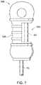
- an endodontic hand file 10Amay be formed in a more bulbous shape, where the handle 12A includes the window 18A, similar to that described above.
- FIG. 7is just one example of various shapes for the handle 12, 12A, and other like shapes are contemplated within the scope of the present invention.
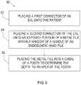
- a method 80 for measuring a tooth canal depthmay include a first step 82 of placing a first connector (i.e., connector 36) of an EAL onto the patient, such as on the patient's mouth or lip.
- a second step 84includes placing a second connector (i.e., connector 38) of the EAL onto an exposed portion (i.e., exposed portion 20) of a metal file (i.e., metal file 14) within a window (i.e., window 18) of a handle (i.e., handle 12) of an endodontic hand file.
- the exposed portionis typically between a bottom of the handle and below a top of the handle.
- a further step 86includes placing the metal file into a canal of a tooth to determine the depth to an apex of the tooth.
Landscapes
- Health & Medical Sciences (AREA)
- Life Sciences & Earth Sciences (AREA)
- General Health & Medical Sciences (AREA)
- Engineering & Computer Science (AREA)
- Veterinary Medicine (AREA)
- Public Health (AREA)
- Animal Behavior & Ethology (AREA)
- Oral & Maxillofacial Surgery (AREA)
- Dentistry (AREA)
- Epidemiology (AREA)
- Biomedical Technology (AREA)
- Surgery (AREA)
- Neurology (AREA)
- Nuclear Medicine, Radiotherapy & Molecular Imaging (AREA)
- Neurosurgery (AREA)
- Biophysics (AREA)
- Dental Tools And Instruments Or Auxiliary Dental Instruments (AREA)
Description
- The invention relates to an endodontic hand file having an exposed window in its handle for attachment to an electronic apex locator.
- The following background information may present examples of specific aspects of the prior art (e.g., without limitation, approaches, facts, or common wisdom) that, while expected to be helpful to further educate the reader as to additional aspects of the prior art, is not to be construed as limiting the present invention, or any embodiments thereof, to anything stated or implied therein or inferred thereupon.
- Referring to
FIG. 1 , anendodontic hand file 100 has ametal shaft 104 and aplastic handle 102.Such hand files 100 are commonly used to measure the length of a root canal in a tooth with the aid of an electronic apex locator (EAL). This instrument, due to its fine point and size, is able to enter and penetrate the root canal of a tooth and reach the end of the root "apex" via negotiations that are done along the way inside of the canal. Once the endodontic hand file reaches the terminus of the canal, it is able to act like a measuring device. This measurement can be accomplished by placing the endodontic hand file in the root canal and then attaching a connector from the EAL to the metal shaft of the file to complete an electronic circuit. The EAL is a digital machine that, in turn, can give a reading based on the position of the endodontic hand file and hence calculate the length of the root canal from an arbitrary point on the surface of the tooth to the terminus of the canal where the file tip is located. - One problem commonly encountered by conventional
endodontic hand files 100 is one of access to itsmetal shaft 104. Currently, the best way to attach the EAL to the file is by means of a clasp, which is at one end attached to the EAL and at the other end to themetal shaft 104 of the file. This method of measurement brings its own set of problems and inaccuracies when the length of the root is close to the length of the file. The files are manufactured with three lengths - 21mm, 25mm and 31mm, which is standard of any file used in the field of endodontics. There is also aplastic stopper 106, about 2mm thick, on the body of the file to facilitate the measurement. The most common problem and challenge faced by a user when using such files is when the root length is approximately the same as the file length, meaning that if the root canal length is 20.5mm, a standard 21mm file cannot be used to measure such length, as the actual working length is just shy of 20mm. Should the user switch the file to a longer one, for example, a 25mm file, it may be too long and not fit in the small working area within the surface of the tooth. - Moreover, when endodontics is performed on teeth with metal crowns, the metal shaft of the endodontic hand file can contact the metal restoration, creating a problem with canal measurement. Insulating sheaths can be used to cover the file shaft, but they may also limit access to the file shaft for contact with the EAL probe.
- The relevant prior art comprises the patent application
FR 1424534 A FR 1 424 534 A - In view of the foregoing, there is a need for improved dental instruments to help facilitate the procedure of root canal therapy.
- The invention is defined by an endodontic file with the features of claim 1. Preferred embodiments of the invention are defined in the dependent claims.
- In some embodiments, the extension portion is angled toward the longitudinal axis of the first portion of the file.
- In some embodiments, the window is formed as an indentation into the handle of the file.
- In some embodiments, the depth of the indentation is less than about 50% of the thickness of the handle.
- These and other features, aspects and advantages of the present invention will become better understood with reference to the following drawings, description and claims.
FIG. 1 illustrates a conventional endodontic hand file used in root canal therapy;FIG. 2 illustrates a partially cut away view of an endodontic hand file according to an exemplary embodiment of the present invention;FIG. 2A illustrates a detailed view of the handle of the endodontic hand file ofFIG. 2 , with the body of the handle shown in shadow to illustrate the extension of the metal shaft therethrough;FIG. 3 illustrates a schematic representation of the endodontic hand file ofFIG. 2 is use with an electronic apex locator during root canal therapy on a patient;FIG. 4 illustrates a side view of an endodontic hand file according to an exemplary embodiment of the present invention;FIG. 5 illustrates a detailed view of the handle of the endodontic hand file ofFIG. 4 ;FIG. 6 illustrates a side view of the metal file and its extension into the file handle used in the endodontic hand file ofFIG. 4 ;FIG. 7 illustrates a detailed side view of an endodontic hand file having an alternate handle shape, according to an exemplary embodiment of the present invention; andFIG. 8 illustrates a method for determining the depth of a tooth's root canal according to an exemplary embodiment of the present invention.- Unless otherwise indicated illustrations in the figures are not necessarily drawn to scale.
- The invention and its various embodiments can now be better understood by turning to the following detailed description wherein illustrated embodiments are described. It is to be expressly understood that the illustrated embodiments are set forth as examples and not by way of limitations on the invention as ultimately defined in the claims.
- The terminology used herein is for the purpose of describing particular embodiments only and is not intended to be limiting of the invention. As used herein, the term "and/or" includes any and all combinations of one or more of the associated listed items. As used herein, the singular forms "a," "an," and "the" are intended to include the plural forms as well as the singular forms, unless the context clearly indicates otherwise. It will be further understood that the terms "comprises" and/or "comprising," when used in this specification, specify the presence of stated features, steps, operations, elements, and/or components, but do not preclude the presence or addition of one or more other features, steps, operations, elements, components, and/or groups thereof.
- Unless otherwise defined, all terms (including technical and scientific terms) used herein have the same meaning as commonly understood by one having ordinary skill in the art to which this invention belongs. It will be further understood that terms, such as those defined in commonly used dictionaries, should be interpreted as having a meaning that is consistent with their meaning in the context of the relevant art and the present disclosure and will not be interpreted in an idealized or overly formal sense unless expressly so defined herein.
- In describing the invention, it will be understood that a number of techniques and steps are disclosed. Each of these has individual benefit and each can also be used in conjunction with one or more, or in some cases all, of the other disclosed techniques. Accordingly, for the sake of clarity, this description will refrain from repeating every possible combination of the individual steps in an unnecessary fashion. Nevertheless, the specification and claims should be read with the understanding that such combinations are entirely within the scope of the invention and the claims.
- In the following description, for purposes of explanation, numerous specific details are set forth in order to provide a thorough understanding of the present invention. It will be evident, however, to one skilled in the art that the present invention may be practiced without these specific details.
- Broadly, embodiments of the present invention provide a dental instrument designed to help facilitate the procedure of root canal therapy. The dental instrument can reduce the inaccuracies that are accompanied using traditional methods of attaching an electronic apex location (EAL) to an endodontic hand file. The endodontic hand file can include an exposed window in the handle of the file that holds an extension of the main body of the file. The clasp from the EAL can attach to this exposed metal in the window of the handle. This new location for attaching the EAL to the hand file can provide an accurate measurement while removing variables such as file movement in the canal, stopper thickness, clearance from the opposing tooth. The endodontic hand file with its exposed window provides a safe, reliable and accurate way of using an EAL to measure the root canal length.
- Referring to
FIGS. 2 and2A , anendodontic hand file 10, also referred to ashand file 10 or simplyfile 10, includes ahandle 12 and ametal file 14 extending from thehandle 12. Themetal file 14 extends into thehandle 12 and further extends along a lengthwise axis thereof. Thefile 10 includes awindow 18 cut into thehandle 12 to expose a portion of themetal file 14 that extends into thehandle 12. Astopper 16 may be disposed about themetal file 14, abutting thehandle 12. Atop portion 22 of thehand file 10 can include indicia to indicate the size of thehand file 10. These indicia may coordinate with currently used indicia used on conventional hand files 100, permitting the user to quickly and easily integrate the hand files 10 of the present invention into their practice. Thehand file 10 may further include ahole 19 formed in thehandle 12, similar to conventional hand files. - Referring now to
FIGS. 2A and3 , in use, themetal file 14 of thehand file 10 may be placed into the root canal of atooth 30 so that the tip of themetal file 14 reaches the apex at adistal end 34 of thetooth 30. Aclamp 38 formed on an end of an EAL clasp-to-file shank extension 32 can attached to an exposedportion 20 of themetal file 14 in thewindow 18 of thehandle 12. Anotherconnector 36 may be disposed within the mouth of a patient to complete the connections for the EAL. The exposedportion 20 may extend from abottom portion 26 of thewindow 18, may continue up to atop portion 24 of thewindow 18 and may further extend through thetop portion 24 into thehandle 12. - Referring now to
FIGS. 4 and5 , thehand file 10 can take various shapes and sizes. Typically, the length and taper of themetal file 14 can correspond to conventional endodontic hand files. Thehandle 12 may also have a length similar to that of conventional hand files, such as from about 8mm to about 12mm, typically about 10mm. Thewindow 18 may have a length from about 3mm to about 7mm, typically about 4.85mm. The depth of thewindow 18 may be from about 30% to about 60% of the depth of the thickness of thehandle 12. In some embodiments, the depth of thewindow 18 may be less than about 50% of the thickness of thehandle 12. In other words, thewindow 18 may cut into thehandle 12 less than half of the handle's thickness. - Referring now additionally to
FIG. 6 , themetal file 14 may be formed as an integral unit. Thehandle 12 may be formed about themetal file 14 starting atlocation 60. In some embodiments, within thehandle 12, themetal file 14 may jog in an elongated Z-pattern from about 1.0mm to about 1.4mm, typically about 1.2mm. Typically, the amount of the jog is sufficient to permit a clasp (i.e.,clasp 38, seeFIG. 3 ) to fit on the exposedportion 20, with a space formed between the exposedportion 20 and thehandle 12. This space may be from about 0.5mm to about 0.9mm, typically about 0.64mm. In other words, the metal file may include afirst bend 62 in a first direction, and asecond bend 64 in a second direction, with a linear portion 66 extending from thesecond bend 64. The angles and orientation of thefirst bend 62 and thesecond bend 64 may be configured such that the linear portion 66 is substantially parallel with themetal file 14 that is inserted into the tooth's root canal, as previously illustrated and described. Thefirst bend 62 and thesecond bend 64 combine to formjog 69, also referred to as offset 69. In some embodiments, thefirst bend 62 and thesecond bend 64 may form angles from about 20 to about 90 degrees, typically from about 30 to about 50 degrees. In some embodiments, a bend end portion 68 (also referred to as extension portion 68) may extend from the linear portion 66 of themetal file 14. Thisbent portion 68 may be angled inward, toward a longitudinal axis of the insertion portion of themetal file 14. The angle formed between thebent portion 68 and the linear portion 66 may be from about 5 to about 15 degrees, typically about 10 degrees. - Referring now to
FIG. 7 , an endodontic hand file 10A may be formed in a more bulbous shape, where thehandle 12A includes thewindow 18A, similar to that described above.FIG. 7 is just one example of various shapes for thehandle - Referring now to
FIG. 8 , amethod 80 for measuring a tooth canal depth may include afirst step 82 of placing a first connector (i.e., connector 36) of an EAL onto the patient, such as on the patient's mouth or lip. Asecond step 84 includes placing a second connector (i.e., connector 38) of the EAL onto an exposed portion (i.e., exposed portion 20) of a metal file (i.e., metal file 14) within a window (i.e., window 18) of a handle (i.e., handle 12) of an endodontic hand file. The exposed portion is typically between a bottom of the handle and below a top of the handle. Afurther step 86 includes placing the metal file into a canal of a tooth to determine the depth to an apex of the tooth. These steps are performed in root canal therapy of a patient.
Claims (10)
- An endodontic hand file (10) comprising:a handle (12);a file (14) having a first portion extending from the handle (12), and a second portion extending into the handle (12);a window (18) formed in a side portion of the handle (12);a first bend (62) of the second portion bending the second portion toward an exterior of the handle (12), the first bend (62) positioned within the handle (12);a second bend (64) of the second portion bending the second portion toward a top end (22) of the handle (12), the second bend (64) positioned within the handle (12), the second bend (64) positioned distal the first bend (62), relative to the first portion; andan exposed portion (20) of the second portion of the file (14) passing into the window (18), the exposed portion (20) being distal the second bend (64), relative to the first portion, a longitudinal axis of the exposed portion (20) being substantially parallel to a longitudinal axis of the first portion.
- The endodontic hand file (10) of claim 1, wherein the exposed portion (20) of the file (14) extends through the window (18) and an extension portion (68) of the file (14) extends back into the handle (12).
- The endodontic hand file (10) of claim 2, wherein the extension portion (68) is angled toward a longitudinal axis of the first portion of the file (14).
- The endodontic hand file (10) of claim 3, wherein an angle between the extension portion (68) and the first portion is from about 5 to about 15 degrees.
- The endodontic hand file (10) of claim 1, wherein the exposed portion (20) has a longitudinal axis that is offset from a longitudinal axis of the first portion of the file (14).
- The endodontic hand file (10) of claim 1, wherein the first portion and the second portion of the file (14) are integrally formed.
- The endodontic hand file (10) of claim 1, wherein the window (18) is formed as an indentation into the handle (12) of the file (14).
- The endodontic hand file (10) of claim 7, wherein a depth of the indentation is less than about 50% of a thickness of the handle (12).
- The endodontic hand file (10) of claim 1, wherein a space is formed entirely about the exposed portion (20).
- The endodontic hand file (10) of claim 1, wherein the second portion of the file (14) includes a jog (69) toward an exterior of the handle (12) inside the handle (12) before the exposed portion (20) extends into the window (18).
Applications Claiming Priority (2)
| Application Number | Priority Date | Filing Date | Title |
|---|---|---|---|
| US15/598,950US10130443B1 (en) | 2017-05-18 | 2017-05-18 | Endodontic hand file and methods for attachment |
| PCT/US2018/032591WO2018213197A1 (en) | 2017-05-18 | 2018-05-14 | Endodontic hand file and methods for attachment |
Publications (3)
| Publication Number | Publication Date |
|---|---|
| EP3624725A1 EP3624725A1 (en) | 2020-03-25 |
| EP3624725A4 EP3624725A4 (en) | 2021-02-24 |
| EP3624725B1true EP3624725B1 (en) | 2022-10-26 |
Family
ID=64176374
Family Applications (1)
| Application Number | Title | Priority Date | Filing Date |
|---|---|---|---|
| EP18802852.6AActiveEP3624725B1 (en) | 2017-05-18 | 2018-05-14 | Endodontic hand file and methods for attachment |
Country Status (4)
| Country | Link |
|---|---|
| US (1) | US10130443B1 (en) |
| EP (1) | EP3624725B1 (en) |
| CN (1) | CN110691560B (en) |
| WO (1) | WO2018213197A1 (en) |
Family Cites Families (43)
| Publication number | Priority date | Publication date | Assignee | Title |
|---|---|---|---|---|
| FR1424534A (en) | 1964-12-02 | 1966-01-14 | Micro Mega Sa | Fixation device of a dental instrument |
| US3924334A (en)* | 1974-06-21 | 1975-12-09 | Sybron Corp | Root canal implement |
| US4028810A (en)* | 1975-08-11 | 1977-06-14 | Karl F. Kinkel | Root canal file |
| SE419400B (en)* | 1980-10-31 | 1981-08-03 | Axelsson P A T | DENTISTRY INSTRUMENTS FOR INVESTIGATING DENTAL LOSS OR TUNAR |
| DE3936211C1 (en)* | 1989-10-31 | 1990-11-08 | Vereinigte Dentalwerke Antaeos-Beutelrock-Zipperer Zdarsky Ehrler Gmbh & Co Kg, 8000 Muenchen, De | |
| JPH09154853A (en)* | 1995-12-07 | 1997-06-17 | Manii Kk | Hand type dental care instrument |
| DE19642431A1 (en) | 1996-10-15 | 1998-04-16 | Coronet Werke Gmbh | Interdental cleaner and process for its manufacture |
| US6074209A (en) | 1998-10-06 | 2000-06-13 | Tulsa Dental Products Inc. | Reduced torque endodontic file |
| CA2320532C (en)* | 1999-09-24 | 2009-02-03 | Nicholas J. Manzoli | Use indicating means for dental files |
| US6638067B2 (en) | 2001-09-04 | 2003-10-28 | Ultradent Products, Inc. | Flocked endodontic files and other flocked devices |
| US6520773B1 (en)* | 2001-09-10 | 2003-02-18 | Joseph C. Weber | Endodontic file |
| WO2003063724A2 (en)* | 2002-01-28 | 2003-08-07 | Lampert Christopher J | Endodontic instrument |
| CA2500644C (en) | 2002-12-05 | 2011-05-24 | Patrick L. Roetzer | Improved dental bur |
| USD497668S1 (en) | 2003-03-11 | 2004-10-26 | Tyco Healthcare Group Lp | Instrument handle |
| US7731498B2 (en) | 2003-05-16 | 2010-06-08 | Mcspadden John T | Endododontic file with multi-tapered flutes |
| US7766657B2 (en) | 2005-08-09 | 2010-08-03 | Andris Jaunberzins | Endodontic file combining active and passive cutting edges |
| US7270541B1 (en) | 2006-03-02 | 2007-09-18 | Johnson William B | Endodontic files having variable helical angle flutes |
| US7938645B2 (en) | 2006-03-16 | 2011-05-10 | Sapian Schubert L | Dental system for root and root tip extraction |
| US20070218420A1 (en)* | 2006-03-16 | 2007-09-20 | Philip John Syribeys | Endodontic instrument with non-conductive coating and method for locating the apex of a tooth |
| USD571043S1 (en) | 2007-04-10 | 2008-06-10 | Ranir, Llc | Interdental device |
| US20090181341A1 (en)* | 2008-01-14 | 2009-07-16 | Lampert Chris J | Endodontic Instrument |
| US8047842B2 (en) | 2008-08-18 | 2011-11-01 | Johnson William B | Reciprocal reverse rotation endodontic file |
| IL204195A (en) | 2010-02-25 | 2013-02-28 | Medic Nrg Ltd | Rotary endodontic file with frictional grip |
| JP5529583B2 (en)* | 2010-02-26 | 2014-06-25 | マニー株式会社 | Dental root canal treatment instrument and manufacturing method thereof |
| EP2460489A1 (en)* | 2010-12-03 | 2012-06-06 | Maillefer Instruments Holding S.À.R.L. | Instrument for boring dental root canals |
| IL212422A0 (en) | 2011-04-17 | 2011-06-30 | Medic Nrg Ltd | Endodontic file and brush |
| USD668339S1 (en) | 2011-04-29 | 2012-10-02 | L-M Instruments Oy | Dental instrument handle |
| USD662206S1 (en) | 2011-05-04 | 2012-06-19 | AlveoLogic LLC | Dental device |
| USD674610S1 (en) | 2011-07-13 | 2013-01-22 | Dennis Eatherton | Interdental cleaner |
| USD700329S1 (en) | 2011-11-28 | 2014-02-25 | Dental Usa, Inc. | Dental tool handle |
| USD679837S1 (en) | 2011-12-19 | 2013-04-09 | Amir Hashem Shahidi Bonjar | Expandable dental micromotor bur |
| DE102012015663A1 (en) | 2012-08-09 | 2014-05-15 | Interbros Gmbh | Interdental cleaners |
| USD744101S1 (en) | 2012-12-04 | 2015-11-24 | Dentsply International Inc. | Dental screw driver |
| USD710009S1 (en) | 2013-02-11 | 2014-07-29 | Charles Maupin | Hybrid endodontic file |
| KR101344570B1 (en)* | 2013-06-14 | 2013-12-26 | 김형우 | Endo pile for dental endodontic treatment |
| USD737443S1 (en) | 2013-06-24 | 2015-08-25 | Karl Storz Gmbh & Co. Kg | Fixation instrument |
| USD714114S1 (en) | 2013-11-04 | 2014-09-30 | Ibt Holdings, Llc | Tool handle |
| US20160302883A1 (en) | 2013-12-05 | 2016-10-20 | Kenneth C. SPRECHMAN | Endodontic file |
| US20150230902A1 (en)* | 2014-02-18 | 2015-08-20 | Panayiotis Andreou | Endodontic file for assessing root canal depth |
| USD747842S1 (en) | 2014-02-26 | 2016-01-26 | Dally-Ann Bressler | Necktie |
| USD742007S1 (en) | 2014-06-04 | 2015-10-27 | Eric J. Schuetz | Angled elevator |
| USD764103S1 (en) | 2014-10-27 | 2016-08-16 | Tepe Munhygienprodukter Ab | Interdental cleaner |
| USD767900S1 (en) | 2015-03-03 | 2016-10-04 | LeedTech Resources Company, LLC | Interdental brush |
- 2017
- 2017-05-18USUS15/598,950patent/US10130443B1/enactiveActive
- 2018
- 2018-05-14EPEP18802852.6Apatent/EP3624725B1/enactiveActive
- 2018-05-14WOPCT/US2018/032591patent/WO2018213197A1/ennot_activeCeased
- 2018-05-14CNCN201880032755.6Apatent/CN110691560B/enactiveActive
Also Published As
| Publication number | Publication date |
|---|---|
| CN110691560B (en) | 2021-03-16 |
| EP3624725A4 (en) | 2021-02-24 |
| CN110691560A (en) | 2020-01-14 |
| WO2018213197A1 (en) | 2018-11-22 |
| EP3624725A1 (en) | 2020-03-25 |
| US20180333223A1 (en) | 2018-11-22 |
| US10130443B1 (en) | 2018-11-20 |
Similar Documents
| Publication | Publication Date | Title |
|---|---|---|
| US5044951A (en) | Dental space and periodontal cavity measuring instrument | |
| US6390814B1 (en) | Endodontic appliance which stops instruments from extending too far into a root canal during treatment | |
| US7121827B2 (en) | Endodontic instrument | |
| US7600325B2 (en) | Bone measurement device for use during oral implant surgery | |
| US4252522A (en) | Dental mirror with endodontic file measuring surface | |
| US4959014A (en) | Dental space measuring instrument | |
| US5193999A (en) | Abutment selector | |
| US20050227198A1 (en) | Combination dental mirror and measurement gauge | |
| JP2024001348A (en) | Root canal length measurement device attachment | |
| EP3530231A1 (en) | Dental retractor | |
| US4708651A (en) | Endodontic root canal file bending pliers | |
| EP3624725B1 (en) | Endodontic hand file and methods for attachment | |
| US20210401541A1 (en) | Endodontic hand file and methods for attachment | |
| US20090181341A1 (en) | Endodontic Instrument | |
| US20190125508A1 (en) | Endodontic hand file and methods for attachment | |
| KR100735423B1 (en) | Endo gauge | |
| US6872075B2 (en) | Endodontic file with a metallic conductor as part of the plastic handle to facilitate use of electronic apex locators | |
| Ruddle | Shaping complex canals: clinical strategy and technique | |
| US20200330205A1 (en) | Endodontic devices | |
| JP6391051B2 (en) | Working length setting / measurement tool for medical instruments | |
| CN216318165U (en) | An alveolar ridge thickness measuring ruler for oral implants | |
| US12440307B2 (en) | Apex locator attachment | |
| JP6357014B2 (en) | Measurement jig | |
| JP3038160U (en) | Dental finger ruler | |
| JP2000014680A (en) | Reamer file with scale |
Legal Events
| Date | Code | Title | Description |
|---|---|---|---|
| STAA | Information on the status of an ep patent application or granted ep patent | Free format text:STATUS: THE INTERNATIONAL PUBLICATION HAS BEEN MADE | |
| PUAI | Public reference made under article 153(3) epc to a published international application that has entered the european phase | Free format text:ORIGINAL CODE: 0009012 | |
| STAA | Information on the status of an ep patent application or granted ep patent | Free format text:STATUS: REQUEST FOR EXAMINATION WAS MADE | |
| 17P | Request for examination filed | Effective date:20191030 | |
| AK | Designated contracting states | Kind code of ref document:A1 Designated state(s):AL AT BE BG CH CY CZ DE DK EE ES FI FR GB GR HR HU IE IS IT LI LT LU LV MC MK MT NL NO PL PT RO RS SE SI SK SM TR | |
| AX | Request for extension of the european patent | Extension state:BA ME | |
| RAP1 | Party data changed (applicant data changed or rights of an application transferred) | Owner name:APEX ENDODONTIC SOLUTIONS, LP | |
| RIN1 | Information on inventor provided before grant (corrected) | Inventor name:BAGHERI, MOJI | |
| DAV | Request for validation of the european patent (deleted) | ||
| DAX | Request for extension of the european patent (deleted) | ||
| A4 | Supplementary search report drawn up and despatched | Effective date:20210121 | |
| RIC1 | Information provided on ipc code assigned before grant | Ipc:A61C 5/44 20170101ALI20210115BHEP Ipc:A61C 5/42 20170101AFI20210115BHEP | |
| GRAP | Despatch of communication of intention to grant a patent | Free format text:ORIGINAL CODE: EPIDOSNIGR1 | |
| STAA | Information on the status of an ep patent application or granted ep patent | Free format text:STATUS: GRANT OF PATENT IS INTENDED | |
| INTG | Intention to grant announced | Effective date:20220510 | |
| RIN1 | Information on inventor provided before grant (corrected) | Inventor name:BAGHERI, MOJI | |
| GRAS | Grant fee paid | Free format text:ORIGINAL CODE: EPIDOSNIGR3 | |
| GRAA | (expected) grant | Free format text:ORIGINAL CODE: 0009210 | |
| STAA | Information on the status of an ep patent application or granted ep patent | Free format text:STATUS: THE PATENT HAS BEEN GRANTED | |
| AK | Designated contracting states | Kind code of ref document:B1 Designated state(s):AL AT BE BG CH CY CZ DE DK EE ES FI FR GB GR HR HU IE IS IT LI LT LU LV MC MK MT NL NO PL PT RO RS SE SI SK SM TR | |
| REG | Reference to a national code | Ref country code:GB Ref legal event code:FG4D | |
| REG | Reference to a national code | Ref country code:CH Ref legal event code:EP | |
| REG | Reference to a national code | Ref country code:DE Ref legal event code:R096 Ref document number:602018042327 Country of ref document:DE | |
| REG | Reference to a national code | Ref country code:AT Ref legal event code:REF Ref document number:1526499 Country of ref document:AT Kind code of ref document:T Effective date:20221115 | |
| REG | Reference to a national code | Ref country code:IE Ref legal event code:FG4D | |
| REG | Reference to a national code | Ref country code:LT Ref legal event code:MG9D | |
| REG | Reference to a national code | Ref country code:NL Ref legal event code:MP Effective date:20221026 | |
| REG | Reference to a national code | Ref country code:AT Ref legal event code:MK05 Ref document number:1526499 Country of ref document:AT Kind code of ref document:T Effective date:20221026 | |
| PG25 | Lapsed in a contracting state [announced via postgrant information from national office to epo] | Ref country code:NL Free format text:LAPSE BECAUSE OF FAILURE TO SUBMIT A TRANSLATION OF THE DESCRIPTION OR TO PAY THE FEE WITHIN THE PRESCRIBED TIME-LIMIT Effective date:20221026 | |
| PG25 | Lapsed in a contracting state [announced via postgrant information from national office to epo] | Ref country code:SE Free format text:LAPSE BECAUSE OF FAILURE TO SUBMIT A TRANSLATION OF THE DESCRIPTION OR TO PAY THE FEE WITHIN THE PRESCRIBED TIME-LIMIT Effective date:20221026 Ref country code:PT Free format text:LAPSE BECAUSE OF FAILURE TO SUBMIT A TRANSLATION OF THE DESCRIPTION OR TO PAY THE FEE WITHIN THE PRESCRIBED TIME-LIMIT Effective date:20230227 Ref country code:NO Free format text:LAPSE BECAUSE OF FAILURE TO SUBMIT A TRANSLATION OF THE DESCRIPTION OR TO PAY THE FEE WITHIN THE PRESCRIBED TIME-LIMIT Effective date:20230126 Ref country code:LT Free format text:LAPSE BECAUSE OF FAILURE TO SUBMIT A TRANSLATION OF THE DESCRIPTION OR TO PAY THE FEE WITHIN THE PRESCRIBED TIME-LIMIT Effective date:20221026 Ref country code:FI Free format text:LAPSE BECAUSE OF FAILURE TO SUBMIT A TRANSLATION OF THE DESCRIPTION OR TO PAY THE FEE WITHIN THE PRESCRIBED TIME-LIMIT Effective date:20221026 Ref country code:ES Free format text:LAPSE BECAUSE OF FAILURE TO SUBMIT A TRANSLATION OF THE DESCRIPTION OR TO PAY THE FEE WITHIN THE PRESCRIBED TIME-LIMIT Effective date:20221026 Ref country code:AT Free format text:LAPSE BECAUSE OF FAILURE TO SUBMIT A TRANSLATION OF THE DESCRIPTION OR TO PAY THE FEE WITHIN THE PRESCRIBED TIME-LIMIT Effective date:20221026 | |
| PG25 | Lapsed in a contracting state [announced via postgrant information from national office to epo] | Ref country code:RS Free format text:LAPSE BECAUSE OF FAILURE TO SUBMIT A TRANSLATION OF THE DESCRIPTION OR TO PAY THE FEE WITHIN THE PRESCRIBED TIME-LIMIT Effective date:20221026 Ref country code:PL Free format text:LAPSE BECAUSE OF FAILURE TO SUBMIT A TRANSLATION OF THE DESCRIPTION OR TO PAY THE FEE WITHIN THE PRESCRIBED TIME-LIMIT Effective date:20221026 Ref country code:LV Free format text:LAPSE BECAUSE OF FAILURE TO SUBMIT A TRANSLATION OF THE DESCRIPTION OR TO PAY THE FEE WITHIN THE PRESCRIBED TIME-LIMIT Effective date:20221026 Ref country code:IS Free format text:LAPSE BECAUSE OF FAILURE TO SUBMIT A TRANSLATION OF THE DESCRIPTION OR TO PAY THE FEE WITHIN THE PRESCRIBED TIME-LIMIT Effective date:20230226 Ref country code:HR Free format text:LAPSE BECAUSE OF FAILURE TO SUBMIT A TRANSLATION OF THE DESCRIPTION OR TO PAY THE FEE WITHIN THE PRESCRIBED TIME-LIMIT Effective date:20221026 Ref country code:GR Free format text:LAPSE BECAUSE OF FAILURE TO SUBMIT A TRANSLATION OF THE DESCRIPTION OR TO PAY THE FEE WITHIN THE PRESCRIBED TIME-LIMIT Effective date:20230127 | |
| REG | Reference to a national code | Ref country code:DE Ref legal event code:R097 Ref document number:602018042327 Country of ref document:DE | |
| PG25 | Lapsed in a contracting state [announced via postgrant information from national office to epo] | Ref country code:SM Free format text:LAPSE BECAUSE OF FAILURE TO SUBMIT A TRANSLATION OF THE DESCRIPTION OR TO PAY THE FEE WITHIN THE PRESCRIBED TIME-LIMIT Effective date:20221026 Ref country code:RO Free format text:LAPSE BECAUSE OF FAILURE TO SUBMIT A TRANSLATION OF THE DESCRIPTION OR TO PAY THE FEE WITHIN THE PRESCRIBED TIME-LIMIT Effective date:20221026 Ref country code:EE Free format text:LAPSE BECAUSE OF FAILURE TO SUBMIT A TRANSLATION OF THE DESCRIPTION OR TO PAY THE FEE WITHIN THE PRESCRIBED TIME-LIMIT Effective date:20221026 Ref country code:DK Free format text:LAPSE BECAUSE OF FAILURE TO SUBMIT A TRANSLATION OF THE DESCRIPTION OR TO PAY THE FEE WITHIN THE PRESCRIBED TIME-LIMIT Effective date:20221026 Ref country code:CZ Free format text:LAPSE BECAUSE OF FAILURE TO SUBMIT A TRANSLATION OF THE DESCRIPTION OR TO PAY THE FEE WITHIN THE PRESCRIBED TIME-LIMIT Effective date:20221026 | |
| PG25 | Lapsed in a contracting state [announced via postgrant information from national office to epo] | Ref country code:SK Free format text:LAPSE BECAUSE OF FAILURE TO SUBMIT A TRANSLATION OF THE DESCRIPTION OR TO PAY THE FEE WITHIN THE PRESCRIBED TIME-LIMIT Effective date:20221026 Ref country code:AL Free format text:LAPSE BECAUSE OF FAILURE TO SUBMIT A TRANSLATION OF THE DESCRIPTION OR TO PAY THE FEE WITHIN THE PRESCRIBED TIME-LIMIT Effective date:20221026 | |
| PLBE | No opposition filed within time limit | Free format text:ORIGINAL CODE: 0009261 | |
| STAA | Information on the status of an ep patent application or granted ep patent | Free format text:STATUS: NO OPPOSITION FILED WITHIN TIME LIMIT | |
| 26N | No opposition filed | Effective date:20230727 | |
| PG25 | Lapsed in a contracting state [announced via postgrant information from national office to epo] | Ref country code:SI Free format text:LAPSE BECAUSE OF FAILURE TO SUBMIT A TRANSLATION OF THE DESCRIPTION OR TO PAY THE FEE WITHIN THE PRESCRIBED TIME-LIMIT Effective date:20221026 | |
| REG | Reference to a national code | Ref country code:DE Ref legal event code:R119 Ref document number:602018042327 Country of ref document:DE | |
| REG | Reference to a national code | Ref country code:CH Ref legal event code:PL | |
| PG25 | Lapsed in a contracting state [announced via postgrant information from national office to epo] | Ref country code:MC Free format text:LAPSE BECAUSE OF FAILURE TO SUBMIT A TRANSLATION OF THE DESCRIPTION OR TO PAY THE FEE WITHIN THE PRESCRIBED TIME-LIMIT Effective date:20221026 | |
| REG | Reference to a national code | Ref country code:BE Ref legal event code:MM Effective date:20230531 | |
| PG25 | Lapsed in a contracting state [announced via postgrant information from national office to epo] | Ref country code:MC Free format text:LAPSE BECAUSE OF FAILURE TO SUBMIT A TRANSLATION OF THE DESCRIPTION OR TO PAY THE FEE WITHIN THE PRESCRIBED TIME-LIMIT Effective date:20221026 Ref country code:LU Free format text:LAPSE BECAUSE OF NON-PAYMENT OF DUE FEES Effective date:20230514 Ref country code:LI Free format text:LAPSE BECAUSE OF NON-PAYMENT OF DUE FEES Effective date:20230531 Ref country code:CH Free format text:LAPSE BECAUSE OF NON-PAYMENT OF DUE FEES Effective date:20230531 | |
| REG | Reference to a national code | Ref country code:IE Ref legal event code:MM4A | |
| PG25 | Lapsed in a contracting state [announced via postgrant information from national office to epo] | Ref country code:IE Free format text:LAPSE BECAUSE OF NON-PAYMENT OF DUE FEES Effective date:20230514 | |
| PG25 | Lapsed in a contracting state [announced via postgrant information from national office to epo] | Ref country code:IE Free format text:LAPSE BECAUSE OF NON-PAYMENT OF DUE FEES Effective date:20230514 Ref country code:DE Free format text:LAPSE BECAUSE OF NON-PAYMENT OF DUE FEES Effective date:20231201 | |
| PG25 | Lapsed in a contracting state [announced via postgrant information from national office to epo] | Ref country code:IT Free format text:LAPSE BECAUSE OF FAILURE TO SUBMIT A TRANSLATION OF THE DESCRIPTION OR TO PAY THE FEE WITHIN THE PRESCRIBED TIME-LIMIT Effective date:20221026 Ref country code:FR Free format text:LAPSE BECAUSE OF NON-PAYMENT OF DUE FEES Effective date:20230531 Ref country code:BE Free format text:LAPSE BECAUSE OF NON-PAYMENT OF DUE FEES Effective date:20230531 | |
| PG25 | Lapsed in a contracting state [announced via postgrant information from national office to epo] | Ref country code:BG Free format text:LAPSE BECAUSE OF FAILURE TO SUBMIT A TRANSLATION OF THE DESCRIPTION OR TO PAY THE FEE WITHIN THE PRESCRIBED TIME-LIMIT Effective date:20221026 | |
| PG25 | Lapsed in a contracting state [announced via postgrant information from national office to epo] | Ref country code:BG Free format text:LAPSE BECAUSE OF FAILURE TO SUBMIT A TRANSLATION OF THE DESCRIPTION OR TO PAY THE FEE WITHIN THE PRESCRIBED TIME-LIMIT Effective date:20221026 | |
| PGFP | Annual fee paid to national office [announced via postgrant information from national office to epo] | Ref country code:GB Payment date:20250501 Year of fee payment:8 | |
| PG25 | Lapsed in a contracting state [announced via postgrant information from national office to epo] | Ref country code:CY Free format text:LAPSE BECAUSE OF FAILURE TO SUBMIT A TRANSLATION OF THE DESCRIPTION OR TO PAY THE FEE WITHIN THE PRESCRIBED TIME-LIMIT; INVALID AB INITIO Effective date:20180514 | |
| PG25 | Lapsed in a contracting state [announced via postgrant information from national office to epo] | Ref country code:HU Free format text:LAPSE BECAUSE OF FAILURE TO SUBMIT A TRANSLATION OF THE DESCRIPTION OR TO PAY THE FEE WITHIN THE PRESCRIBED TIME-LIMIT; INVALID AB INITIO Effective date:20180514 |