EP3624149B1 - Ferroresonant transformer for use in uninterruptible power supplies - Google Patents
Ferroresonant transformer for use in uninterruptible power suppliesDownload PDFInfo
- Publication number
- EP3624149B1 EP3624149B1EP19205746.1AEP19205746AEP3624149B1EP 3624149 B1EP3624149 B1EP 3624149B1EP 19205746 AEP19205746 AEP 19205746AEP 3624149 B1EP3624149 B1EP 3624149B1
- Authority
- EP
- European Patent Office
- Prior art keywords
- windings
- output
- section
- inverter
- ferroresonant transformer
- Prior art date
- Legal status (The legal status is an assumption and is not a legal conclusion. Google has not performed a legal analysis and makes no representation as to the accuracy of the status listed.)
- Active
Links
Images


Classifications
- H—ELECTRICITY
- H02—GENERATION; CONVERSION OR DISTRIBUTION OF ELECTRIC POWER
- H02J—CIRCUIT ARRANGEMENTS OR SYSTEMS FOR SUPPLYING OR DISTRIBUTING ELECTRIC POWER; SYSTEMS FOR STORING ELECTRIC ENERGY
- H02J9/00—Circuit arrangements for emergency or stand-by power supply, e.g. for emergency lighting
- H02J9/04—Circuit arrangements for emergency or stand-by power supply, e.g. for emergency lighting in which the distribution system is disconnected from the normal source and connected to a standby source
- H02J9/06—Circuit arrangements for emergency or stand-by power supply, e.g. for emergency lighting in which the distribution system is disconnected from the normal source and connected to a standby source with automatic change-over, e.g. UPS systems
- H02J9/062—Circuit arrangements for emergency or stand-by power supply, e.g. for emergency lighting in which the distribution system is disconnected from the normal source and connected to a standby source with automatic change-over, e.g. UPS systems for AC powered loads
- H—ELECTRICITY
- H01—ELECTRIC ELEMENTS
- H01F—MAGNETS; INDUCTANCES; TRANSFORMERS; SELECTION OF MATERIALS FOR THEIR MAGNETIC PROPERTIES
- H01F38/00—Adaptations of transformers or inductances for specific applications or functions
- H01F38/14—Inductive couplings
- H—ELECTRICITY
- H01—ELECTRIC ELEMENTS
- H01F—MAGNETS; INDUCTANCES; TRANSFORMERS; SELECTION OF MATERIALS FOR THEIR MAGNETIC PROPERTIES
- H01F27/00—Details of transformers or inductances, in general
- H01F27/24—Magnetic cores
- H—ELECTRICITY
- H01—ELECTRIC ELEMENTS
- H01F—MAGNETS; INDUCTANCES; TRANSFORMERS; SELECTION OF MATERIALS FOR THEIR MAGNETIC PROPERTIES
- H01F27/00—Details of transformers or inductances, in general
- H01F27/28—Coils; Windings; Conductive connections
- H—ELECTRICITY
- H01—ELECTRIC ELEMENTS
- H01F—MAGNETS; INDUCTANCES; TRANSFORMERS; SELECTION OF MATERIALS FOR THEIR MAGNETIC PROPERTIES
- H01F27/00—Details of transformers or inductances, in general
- H01F27/40—Structural association with built-in electric component, e.g. fuse
- H—ELECTRICITY
- H02—GENERATION; CONVERSION OR DISTRIBUTION OF ELECTRIC POWER
- H02J—CIRCUIT ARRANGEMENTS OR SYSTEMS FOR SUPPLYING OR DISTRIBUTING ELECTRIC POWER; SYSTEMS FOR STORING ELECTRIC ENERGY
- H02J9/00—Circuit arrangements for emergency or stand-by power supply, e.g. for emergency lighting
- H02J9/04—Circuit arrangements for emergency or stand-by power supply, e.g. for emergency lighting in which the distribution system is disconnected from the normal source and connected to a standby source
- H02J9/06—Circuit arrangements for emergency or stand-by power supply, e.g. for emergency lighting in which the distribution system is disconnected from the normal source and connected to a standby source with automatic change-over, e.g. UPS systems
- H02J9/067—Circuit arrangements for emergency or stand-by power supply, e.g. for emergency lighting in which the distribution system is disconnected from the normal source and connected to a standby source with automatic change-over, e.g. UPS systems using multi-primary transformers, e.g. transformer having one primary for each AC energy source and a secondary for the loads
- Y—GENERAL TAGGING OF NEW TECHNOLOGICAL DEVELOPMENTS; GENERAL TAGGING OF CROSS-SECTIONAL TECHNOLOGIES SPANNING OVER SEVERAL SECTIONS OF THE IPC; TECHNICAL SUBJECTS COVERED BY FORMER USPC CROSS-REFERENCE ART COLLECTIONS [XRACs] AND DIGESTS
- Y10—TECHNICAL SUBJECTS COVERED BY FORMER USPC
- Y10T—TECHNICAL SUBJECTS COVERED BY FORMER US CLASSIFICATION
- Y10T29/00—Metal working
- Y10T29/49—Method of mechanical manufacture
- Y10T29/49002—Electrical device making
- Y10T29/4902—Electromagnet, transformer or inductor
- Y10T29/49073—Electromagnet, transformer or inductor by assembling coil and core
Definitions
- the present inventionrelates the generation of a standby power signal and, more specifically, to uninterruptible power supply systems and methods using ferroresonant transformers.
- UPSUninterruptible power supplies
- a UPSis configured to switch between a primary power source and a standby power source as necessary to maintain constant power to a load.
- the primary power sourcemay be a utility power supply
- the standby power sourcemay take the form of a battery system.
- the UPSwill normally operate in a line mode in which the utility power signal is passed to the load when the utility power signal is within predefined parameters. In the line mode, the UPS will typically also charge the battery system. When the utility power falls outside of the predefined parameters, the UPS will switch to standby mode in which an AC signal is generated based on the energy stored in the battery system.
- a class of UPS'semploys a ferroresonant transformer.
- a ferroresonant transformeris a saturating transformer that employs a tank circuit comprised of a resonant winding and capacitor to produce a nearly constant average output even if the input to the transformer varies.
- a typical UPS employing a ferroresonant transformertakes advantage of the voltage regulating properties of a ferroresonant transformer in both line and standby modes. In the context of a UPS, a ferroresonant transformer thus provides surge suppression, isolation, short circuit protection, and voltage regulation without the use of active components.
- a conventional ferroresonant transformer used in a UPSwill further comprise input windings and inverter (resonant) windings arranged on the primary or input side and output windings on the secondary or output side.
- GB 2137033 Adescribes an uninterruptible AC power supply that permits parallel operation between a commercial AC line and an inverter unit.
- the uninterruptible AC power supplyis comprised of an iron core divided with magnetic shunts into three sections and has an output winding, a winding for a commercial AC line and a winding for an inverter unit, one each wound on the aforementioned three sections of the iron core.
- the three windingsare so disposed that the output winding is wound on one terminal section and the windings for the commercial AC line and the inverter unit are wound on the remaining two sections.
- WO 00/21180 A1describes an uninterruptible power supply system for producing an AC voltage from at least one of a DC power source or an AC power source.
- the uninterruptible power supply systemincludes an input terminal configured to receive an AC voltage from an AC power source, and an inverter operative to produce an AC voltage at an output thereof from a DC power source.
- a ferroresonant transformer circuitincludes a transformer having an input winding, an output winding, and a third winding that forms part of a resonant circuit that produces saturation in the output winding when an AC voltage on the input winding exceeds a predetermined amplitude.
- a transformer input control circuitis coupled to the input terminal and to the inverter output and is operative to couple at least one of the input terminal and the inverter output to the input winding.
- the transformer input control circuitvariably couples the input terminal to the input winding responsive to at least one of a voltage at the input terminal, a current in the output winding, a voltage on the output winding and a current at the input terminal.
- An object of the present inventionis to provide improved ferroresonant transformers for use in UPS systems.
- the present inventionprovides an uninterruptible power supply for supplying power to a load and a method of supplying power to a load, as set out in independent claims 1 and 8 respectively. Preferred embodiments are defined in the dependent claims.
- a ferroresonant transformercomprising a core, a main shunt, first windings, second windings, and third windings.
- the main shuntarranged relative to the core to define a primary side and a secondary side of the ferroresonant transformer.
- the first windingsare arranged on the primary side of the ferroresonant transformer and are operatively connected to the primary power source.
- the second windingsare arranged on the secondary side of the ferroresonant transformer and are operatively connected to the secondary power source.
- the third windingsare arranged on the secondary side of the ferroresonant transformer and are operatively connected to the resonant capacitor.
- a first output signalis present on at least a portion of the third windings.
- a secondary poweris present on the second windings, a second output signal is present on at least a portion of the third windings.
- an uninterruptible power supplyfor supplying power to a load comprising a transformer, a resonant capacitor, a primary power source, and a secondary power source.
- the transformercomprises a core, a main shunt arranged relative to the core to define a primary side and a secondary side of the transformer, first windings arranged on the primary side of the transformer, second windings arranged on the secondary side of the transformer, and third windings arranged on the secondary side of the transformer.
- the resonant capacitoris operatively connected to the third windings.
- the primary power sourceis operatively connected to the first windings.
- the secondary power sourceis operatively connected to the second windings.
- the loadis connected to at least a portion of the third windings.
- the primary power sourcecauses a primary signal to be present on the first windings such that a first output signal supplied to the load based on the primary signal.
- the secondary power sourcecauses a secondary signal to be present on the second windings such that a second output signal is supplied to the load based on the secondary signal.
- a main shuntis arranged relative to a core to define a primary side and a secondary side.
- First windingsare arranged on the primary side, while second and third windings are arranged on the secondary side.
- a resonant capacitoris operatively connected to the third windings.
- a primary power sourceis operatively connected to the first windings.
- a secondary power sourceis operatively connected to the second windings.
- the loadis operatively connected to at least a portion of the third windings.
- the primary power sourcecauses a primary signal to be present on the first windings such that a first output signal supplied to the load.
- the secondary power sourcecauses a secondary signal to be present on the second windings such that a second output signal is supplied to the load.
- UPSuninterruptible power supply
- the example UPS system 20supplies power to a load 22 based on a primary power signal present on an AC power line 24 (line mode) or a secondary power signal generated by a battery pack 26 (standby mode). While the example secondary power signal is generated by a battery pack in the example UPS system 20, alternative power sources such as generators, fuel cells, solar cells, and the like may be used as the secondary power source.
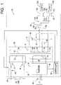
- the example UPS system 20comprises an input section 30, an output section 32, an inverter section 34, a cable assembly 36, and a ferroresonant transformer 38.
- the example input section 30comprises a main switch 40 and first and second select switches 42 and 44.
- the example output section 32comprises an output or resonant capacitor 50 and, optionally, a select switch 52 and a filter capacitor 54.
- the output capacitor 50forms a resonant or tank circuit with the transformer 38 as will be described in further detail below.
- the select switch 52is open, the output capacitor 50 is removed from the circuit formed by the output section 32 and transformer 38, and the filter capacitor 54 filters the output of this circuit.
- the inverter section 34comprises an inverter circuit 60.
- the inverter circuit 60may be an H-bridge circuit or any other circuit capable of producing an appropriate AC power signal based on a DC power signal obtained from the battery pack 26.
- the inverter circuit 60is pulse-width modulated, and the inverter section 34 functions as a switch mode power supply when the UPS system operates in the standby mode.
- the inverter section 34 and the inverter circuit 60are or may be conventional and will not be described herein in further detail.
- a controller 62may be optionally included in the inverter section 34. If used, the controller 62 operates the switches 40 and 52 and controls the inverter circuit 60. The controller 62 may further control the charging of the battery pack 26 when the UPS system 20 operates in line mode based on the temperature, voltage, and/or current signals associated with the battery pack 26.
- the ferroresonant transformer 38comprises a core 70, input windings 72, an inductor 74, inverter windings 76, and output windings 78.
- the core 70is or may be a conventional laminate structure.
- the inductor 74defines a primary side 80 and a secondary side 82 of the transformer 38.
- only the input windings 72are on the primary side 80 of the transformer 38.
- the inverter windings 76 and output windings 78are on the secondary side 82 of the transformer 38.
- the output windings 78are arranged between the inverter windings 76 and the inductor 74
- the inductor 74is arranged between the output windings 78 and the input windings 72.
- the transformer 38 depicted in FIGS. 1 and 2defines the following arrangement of windings and shunts: the input windings 72, a large (or main) shunt formed by the inductor 74, output windings 78, and inverter windings 76.
- FIGS. 3 and 5further illustrate that, in the example transformer 38, a small (or minor) shunt 90 is arranged between the output windings 78 and the inverter windings 76.
- the small shunt 90does not significantly affect the electromagnetic properties of the transformer 38 in the context of the overall UPS system 20 but is used in the example transformer 38 to allow the transformer 38 to operate as described herein in the context of the UPS system 20.
- the AC power line 24forms a primary power source that causes a primary signal to be present on the input windings 72.
- the input windings 72are electromagnetically coupled to the output windings 78 such that a first output signal is supplied to one or both of the loads 22a and 22b when the UPS system 20 operates in the line mode.
- the battery pack 26 and inverter section 34form a secondary power source that causes a secondary signal to be present on the inverter windings 76.
- the inverter windings 76are electromagnetically coupled to the output windings 78 such that a second output signal is supplied to one or both of the loads 22a and 22b when the UPS system 20 operates in the standby mode.
- the construction details of the transformer 38are not critical to the general principles of the present invention and will depend upon a particular implementation of the UPS system 20 in which the transformer 38 is designed to operate.
- the example transformer 38has the following characteristics: stacking 3 x 3 interleaved stack height approximately 109.73 MM (4.32") shunts positioned in cores such that there is equal overhang on both sides keeper cut from E lamination at both ends of stack; tape tightly across keeper after E-I compaction to reduce noise lamination compact E-I lamination together without air gap sleevings nylon sleevings used with bolts shims use wood shims to fill in gaps between windings and core small shunt approximately 2.00 mm (0.075") thick (4 pcs grade H50 or 3 pcs M54 shunt lamination); polyester tape large shunt approximately 16 mm (0.625") thick (stack height adjusted to meet short circuit current requirement); polyester tape core E-1 lamination; grain orientation as shown in FIG. 3 varnish penetrate at
- the example cable assembly 36connects the output section 32 to one of first and second example loads 22a or 22b.
- the cable assembly 36comprises first and second winding connectors 120 and 122 operatively connected to a first end 124 of the output windings 78.
- a second end 126 of the output windings 78is connected to the output capacitor 50.
- the cable assembly 36further comprises first and second tap connectors 130 and 132 operatively connected to first and second intermediate points 134 and 136, respectively, of the output windings 78.
- the example cable assembly 36additionally comprises a selection cable 140 comprising a selection connector 142 and first and second output connectors 144 and 146.
- the first load 22acomprises first and second load connectors 150 and 152
- the second load 22bcomprises second and third load connectors 154 and 156.
- the selection connector 142is connected to either the first tap connector 130 or the second tap connector 132 depending upon the voltage requirements of the loads 22a and 22b.
- the first and third load connectors 150 and 154are connected to the first and second winding connectors 120 and 122, and the second and fourth winding connectors 152 and 156 are connected to the first and second output connectors 144 and 146, respectively.
- the cable assembly 36thus allows one or both of the loads 22a and 22b to be connected to the output section 32 and the output windings 78 and, more specifically, to an appropriate portion of the output windings 78 as determined by the first and second tap connectors 130 and 132.
- the selection of the appropriate tap connector 130 or 132is based on the voltage requirements of the loads 22a and 22b.
Landscapes
- Engineering & Computer Science (AREA)
- Power Engineering (AREA)
- Business, Economics & Management (AREA)
- Emergency Management (AREA)
- Inverter Devices (AREA)
- Stand-By Power Supply Arrangements (AREA)
- Dc-Dc Converters (AREA)
- Charge And Discharge Circuits For Batteries Or The Like (AREA)
- Coils Or Transformers For Communication (AREA)
Description
- The present invention relates the generation of a standby power signal and, more specifically, to uninterruptible power supply systems and methods using ferroresonant transformers.
- Uninterruptible power supplies (UPS's) have long been used to provide at least temporary auxiliary power to electronic devices. Typically, a UPS is configured to switch between a primary power source and a standby power source as necessary to maintain constant power to a load.
- For example, the primary power source may be a utility power supply, and the standby power source may take the form of a battery system. The UPS will normally operate in a line mode in which the utility power signal is passed to the load when the utility power signal is within predefined parameters. In the line mode, the UPS will typically also charge the battery system. When the utility power falls outside of the predefined parameters, the UPS will switch to standby mode in which an AC signal is generated based on the energy stored in the battery system.
- A class of UPS's employs a ferroresonant transformer. A ferroresonant transformer is a saturating transformer that employs a tank circuit comprised of a resonant winding and capacitor to produce a nearly constant average output even if the input to the transformer varies. A typical UPS employing a ferroresonant transformer takes advantage of the voltage regulating properties of a ferroresonant transformer in both line and standby modes. In the context of a UPS, a ferroresonant transformer thus provides surge suppression, isolation, short circuit protection, and voltage regulation without the use of active components.
- Conventionally, a ferroresonant transformer configured for use in a UPS system includes a core and an inductor arranged relative to the core to define: (a) a primary or input side of the transformer and (b) a secondary or output side of the transformer. A conventional ferroresonant transformer used in a UPS will further comprise input windings and inverter (resonant) windings arranged on the primary or input side and output windings on the secondary or output side.
GB 2137033 A WO 00/21180 A1 - An object of the present invention is to provide improved ferroresonant transformers for use in UPS systems.
- The present invention provides an uninterruptible power supply for supplying power to a load and a method of supplying power to a load, as set out in
independent claims 1 and 8 respectively. Preferred embodiments are defined in the dependent claims. - There is provided a ferroresonant transformer comprising a core, a main shunt, first windings, second windings, and third windings. The main shunt arranged relative to the core to define a primary side and a secondary side of the ferroresonant transformer. The first windings are arranged on the primary side of the ferroresonant
transformer and are operatively connected to the primary power source. The second windings are arranged on the secondary side of the ferroresonant transformer and are operatively connected to the secondary power source. The third windings are arranged on the secondary side of the ferroresonant transformer and are operatively connected to the resonant capacitor. When a primary signal is present on the first windings, a first output signal is present on at least a portion of the third windings. When a secondary power is present on the second windings, a second output signal is present on at least a portion of the third windings. - There is further provided an uninterruptible power supply for supplying power to a load comprising a transformer, a resonant capacitor, a primary power source, and a secondary power source. The transformer comprises a core, a main shunt arranged relative to the core to define a primary side and a secondary side of the transformer, first windings arranged on the primary side of the transformer, second windings arranged on the secondary side of the transformer, and third windings arranged on the secondary side of the transformer. The resonant capacitor is operatively connected to the third windings. The primary power source is operatively connected to the first windings. The secondary power source is operatively connected to the second windings. The load is connected to at least a portion of the third windings. In a line mode, the primary power source causes a primary signal to be present on the first windings such that a first output signal supplied to the load based on the primary signal. In a standby mode, the secondary power source causes a secondary signal to be present on the second windings such that a second output signal is supplied to the load based on the secondary signal.
- There is provided a method of supplying uninterruptible power to a load comprising the following steps. A main shunt is arranged relative to a core to define a primary side and a
secondary side. First windings are arranged on the primary side, while second and third windings are arranged on the secondary side. A resonant capacitor is operatively connected to the third windings. A primary power source is operatively connected to the first windings. A secondary power source is operatively connected to the second windings. The load is operatively connected to at least a portion of the third windings. When operating in a line mode, the primary power source causes a primary signal to be present on the first windings such that a first output signal supplied to the load. When operating in a standby mode, the secondary power source causes a secondary signal to be present on the second windings such that a second output signal is supplied to the load. FIG. 1 is a simplified block diagram of a first embodiment of an uninterruptible power supply system using a ferroresonant transformer system constructed in accordance with, and embodying, the principles of the present invention;FIG. 2 is a somewhat schematic view of a ferroresonant transformer forming a part of the UPS system depicted inFIG. 1 ;FIG. 3 is a perspective view of the ferroresonant transformer depicted inFIG. 2 ;FIG. 4 is a side elevation view of the ferroresonant transformer depicted inFIGS. 2 and 3 ; andFIG. 5 is a section view taken along lines 5-5 inFIG. 4 .- Referring initially to
FIG. 1 of the drawing, depicted therein is a first example of an uninterruptible power supply (UPS)system 20 constructed in accordance with, and embodying, the principles of the present invention. - The example UPS
system 20 supplies power to a load 22 based on a primary power signal present on an AC power line 24 (line mode) or a secondary power signal generated by a battery pack 26 (standby mode). While the example secondary power signal is generated by a battery pack in theexample UPS system 20, alternative power sources such as generators, fuel cells, solar cells, and the like may be used as the secondary power source. - The
example UPS system 20 comprises aninput section 30, anoutput section 32, aninverter section 34, acable assembly 36, and aferroresonant transformer 38. - The
example input section 30 comprises amain switch 40 and first and secondselect switches example output section 32 comprises an output orresonant capacitor 50 and, optionally, aselect switch 52 and afilter capacitor 54. - When the
select switch 52 is closed, theoutput capacitor 50 forms a resonant or tank circuit with thetransformer 38 as will be described in further detail below. When theselect switch 52 is open, theoutput capacitor 50 is removed from the circuit formed by theoutput section 32 andtransformer 38, and thefilter capacitor 54 filters the output of this circuit. - The
inverter section 34 comprises aninverter circuit 60. Theinverter circuit 60 may be an H-bridge circuit or any other circuit capable of producing an appropriate AC power signal based on a DC power signal obtained from thebattery pack 26. In particular, theinverter circuit 60 is pulse-width modulated, and theinverter section 34 functions as a switch mode power supply when the UPS system operates in the standby mode. Theinverter section 34 and theinverter circuit 60 are or may be conventional and will not be described herein in further detail. - A
controller 62 may be optionally included in theinverter section 34. If used, thecontroller 62 operates theswitches inverter circuit 60. Thecontroller 62 may further control the charging of thebattery pack 26 when theUPS system 20 operates in line mode based on the temperature, voltage, and/or current signals associated with thebattery pack 26. - The
ferroresonant transformer 38 comprises a core 70,input windings 72, aninductor 74,inverter windings 76, andoutput windings 78. Thecore 70 is or may be a conventional laminate structure. As shown inFIG. 2 , theinductor 74 defines aprimary side 80 and asecondary side 82 of thetransformer 38. In theexample transformer 38, only theinput windings 72 are on theprimary side 80 of thetransformer 38. Theinverter windings 76 andoutput windings 78 are on thesecondary side 82 of thetransformer 38. In particular, theoutput windings 78 are arranged between theinverter windings 76 and theinductor 74, and theinductor 74 is arranged between theoutput windings 78 and theinput windings 72. - As perhaps best shown in
FIGS. 3 and5 , thetransformer 38 depicted inFIGS. 1 and2 defines the following arrangement of windings and shunts: theinput windings 72, a large (or main) shunt formed by theinductor 74,output windings 78, andinverter windings 76.FIGS. 3 and5 further illustrate that, in theexample transformer 38, a small (or minor)shunt 90 is arranged between theoutput windings 78 and theinverter windings 76. Thesmall shunt 90 does not significantly affect the electromagnetic properties of thetransformer 38 in the context of theoverall UPS system 20 but is used in theexample transformer 38 to allow thetransformer 38 to operate as described herein in the context of theUPS system 20. - In the line mode, the
AC power line 24 forms a primary power source that causes a primary signal to be present on theinput windings 72. Theinput windings 72 are electromagnetically coupled to theoutput windings 78 such that a first output signal is supplied to one or both of theloads UPS system 20 operates in the line mode. - In the standby mode, the
battery pack 26 andinverter section 34 form a secondary power source that causes a secondary signal to be present on theinverter windings 76. Theinverter windings 76 are electromagnetically coupled to theoutput windings 78 such that a second output signal is supplied to one or both of theloads UPS system 20 operates in the standby mode. - The construction details of the
transformer 38 are not critical to the general principles of the present invention and will depend upon a particular implementation of theUPS system 20 in which thetransformer 38 is designed to operate. Theexample transformer 38 has the following characteristics:stacking 3 x 3 interleaved stack height approximately 109.73 MM (4.32") shunts positioned in cores such that there is equal overhang on both sides keeper cut from E lamination at both ends of stack; tape tightly across keeper after E-I compaction to reduce noise lamination compact E-I lamination together without air gap sleevings nylon sleevings used with bolts shims use wood shims to fill in gaps between windings and core small shunt approximately 2.00 mm (0.075") thick (4 pcs grade H50 or 3 pcs M54 shunt lamination); polyester tape large shunt approximately 16 mm (0.625") thick (stack height adjusted to meet short circuit current requirement); polyester tape core E-1 lamination; grain orientation as shown in FIG. 3 varnish penetrate at least 80% of the windings and be fully cured - The
example cable assembly 36 connects theoutput section 32 to one of first and second example loads 22a or 22b. In particular, thecable assembly 36 comprises first and second windingconnectors first end 124 of theoutput windings 78. Asecond end 126 of theoutput windings 78 is connected to theoutput capacitor 50. Thecable assembly 36 further comprises first andsecond tap connectors intermediate points output windings 78. Theexample cable assembly 36 additionally comprises aselection cable 140 comprising aselection connector 142 and first andsecond output connectors first load 22a comprises first andsecond load connectors 150 and 152, while thesecond load 22b comprises second andthird load connectors - Using the
example cable assembly 36, theselection connector 142 is connected to either thefirst tap connector 130 or thesecond tap connector 132 depending upon the voltage requirements of theloads third load connectors connectors connectors 152 and 156 are connected to the first andsecond output connectors cable assembly 36 thus allows one or both of theloads output section 32 and theoutput windings 78 and, more specifically, to an appropriate portion of theoutput windings 78 as determined by the first andsecond tap connectors appropriate tap connector loads - Given the foregoing, it should be apparent that the principles of the present invention may be embodied in forms other than those described above. The scope of the present invention should thus be determined only by the appended claims.
Claims (14)
- An uninterruptible power supply (20) for supplying power to a load, the uninterruptible power supply comprising:an input section (30) adapted to be connected to a primary power source;an output section (32) adapted to be connected to the load;an inverter section (34) adapted to be connected to a secondary power source; anda ferroresonant transformer (38) comprisinga core (70),a first shunt (74) arranged relative to the core (70) to define a primary side (80) and a secondary side (82) of the ferroresonant transformer,first windings (72) arranged on the primary side (80) of the ferroresonant transformer, where the first windings (72) are adapted to be connected to the input section (30),second windings (76) arranged on the secondary side (82) of the ferroresonant transformer, where the second windings (82) are connected to the inverter section (34), andthird windings (78) arranged on the secondary side (82) of the ferroresonant transformer, where the third windings (78) are connected to the output section (32);characterised in thatwhen a primary signal from the primary power source is present at the input section (30), the output section (32) may be configured to connect a resonant capacitor (50) to the third windings (78) to form a resonant circuit and a first output signal is present on at least a portion of the third windings (78); andwhen a secondary power signal from the inverter is present at the inverter section (34), the output section (32) may be configured to disconnect the resonant capacitor (50) from the third windings (78) and a second output signal is present on at least a portion of the third windings (78).
- An uninterruptible power supply as recited in claim 1, where the output section (32) comprises the resonant capacitor (50) and an output select switch (52).
- An uninterruptible power supply as recited in claim 1, in which:the input section (30) comprises first and second input select switches (42, 44); andthe first and second input select switches (42, 44) may be operated to connect the primary power source to different portions of the first windings (72).
- An uninterruptible power supply as recited in claim 1, in which:the inverter section (34) comprises an inverter; andthe inverter may be operated such that the second output power signal is present on at least a portion of the third windings (78).
- An uninterruptible power supply as recited in claim 1, in which the first shunt (74) of the ferroresonant transformer (38) is formed by an inductor.
- An uninterruptible power supply as recited in claim 1, in which the ferroresonant transformer (38) further comprises a minor shunt (90) arranged between the second windings (76) and the third windings (78).
- An uninterruptible power supply as recited in claim 1, in which the output section (32) further comprises a filter capacitor (54).
- A method of supplying power to a load, the method comprising the steps of:connecting an input section (30) to a primary power source;connecting an output section (32) to the load;connecting an inverter section (34) to a secondary power source; andproviding a ferroresonant transformer (38) comprisinga core (70),a first shunt (74) arranged relative to the core (70) to define a primary side (80) and a secondary side (82) of the ferroresonant transformer,first windings (72) arranged on the primary side (80) of the ferroresonant transformer,second windings (76) arranged on the secondary side (82) of the ferroresonant transformer, andthird windings (78) arranged on the secondary side (82) of the ferroresonant transformer;connecting the first windings (72) to the input section (30);connecting the second windings (76) to the inverter section (34);connecting the third windings (78) to the output section (32);characterised in thatwhen a primary signal from the primary power source is present at the input section (30), configuring the output section (32) to connect a resonant capacitor (50) to the third windings (78) to form a resonant circuit such that a first output signal is present on at least a portion of the third windings (78); andwhen a secondary power signal from the inverter is present at the inverter section (34), configuring the output section (32) to disconnect the resonant capacitor (50) from the third windings (78) such that a second output signal is present on at least a portion of the third windings (78).
- A method as recited in claim 8, in which the step of providing the output section (32) comprises the step of providing the resonant capacitor (50) and an output select switch (52).
- A method as recited in claim 8, in which:the step of providing the input section (30) comprises the step of providing first and second input select switches (42, 44); andthe first and second input select switches (42, 44) are operated to connect the primary power source to different portions of the first windings (72).
- A method as recited in claim 8, in which:the step of providing the inverter section (34) further comprises the step of providing an inverter; andthe inverter is operated such that the second output power signal is present on at least a portion of the third windings (78).
- A method as recited in claim 8, in which the step of providing the ferroresonant transformer comprises the step of forming the first shunt with an inductor.
- A method as recited in claim 8, in which the step of providing the ferroresonant transformer further comprises the step of arranging a minor shunt (90) between the second windings (76) and the third windings (78).
- A method as recited in claim 8, in which the step of providing the output section (32) further comprises the step of providing a filter capacitor (54).
Applications Claiming Priority (4)
| Application Number | Priority Date | Filing Date | Title |
|---|---|---|---|
| US30592610P | 2010-02-18 | 2010-02-18 | |
| US12/803,787US8575779B2 (en) | 2010-02-18 | 2010-07-07 | Ferroresonant transformer for use in uninterruptible power supplies |
| PCT/US2011/025000WO2011103131A2 (en) | 2010-02-18 | 2011-02-16 | Ferroresonant transformer for use in uninterruptible power supplies |
| EP11745144.3AEP2537167B1 (en) | 2010-02-18 | 2011-02-16 | Ferroresonant transformer for use in uninterruptible power supplies |
Related Parent Applications (1)
| Application Number | Title | Priority Date | Filing Date |
|---|---|---|---|
| EP11745144.3ADivisionEP2537167B1 (en) | 2010-02-18 | 2011-02-16 | Ferroresonant transformer for use in uninterruptible power supplies |
Publications (2)
| Publication Number | Publication Date |
|---|---|
| EP3624149A1 EP3624149A1 (en) | 2020-03-18 |
| EP3624149B1true EP3624149B1 (en) | 2022-05-11 |
Family
ID=44369153
Family Applications (2)
| Application Number | Title | Priority Date | Filing Date |
|---|---|---|---|
| EP11745144.3AActiveEP2537167B1 (en) | 2010-02-18 | 2011-02-16 | Ferroresonant transformer for use in uninterruptible power supplies |
| EP19205746.1AActiveEP3624149B1 (en) | 2010-02-18 | 2011-02-16 | Ferroresonant transformer for use in uninterruptible power supplies |
Family Applications Before (1)
| Application Number | Title | Priority Date | Filing Date |
|---|---|---|---|
| EP11745144.3AActiveEP2537167B1 (en) | 2010-02-18 | 2011-02-16 | Ferroresonant transformer for use in uninterruptible power supplies |
Country Status (13)
| Country | Link |
|---|---|
| US (4) | US8575779B2 (en) |
| EP (2) | EP2537167B1 (en) |
| KR (1) | KR101813733B1 (en) |
| CN (1) | CN102906829A (en) |
| AU (1) | AU2011218269B2 (en) |
| BR (1) | BR112012020836B1 (en) |
| CA (1) | CA2790312C (en) |
| CL (1) | CL2012002276A1 (en) |
| MX (1) | MX2012009501A (en) |
| PE (1) | PE20130698A1 (en) |
| PL (1) | PL2537167T3 (en) |
| TW (1) | TWI467608B (en) |
| WO (1) | WO2011103131A2 (en) |
Families Citing this family (15)
| Publication number | Priority date | Publication date | Assignee | Title |
|---|---|---|---|---|
| US8575779B2 (en)* | 2010-02-18 | 2013-11-05 | Alpha Technologies Inc. | Ferroresonant transformer for use in uninterruptible power supplies |
| US9030048B2 (en) | 2010-10-18 | 2015-05-12 | Alpha Technologies Inc. | Uninterruptible power supply systems and methods for communications systems |
| WO2012112252A2 (en) | 2011-01-22 | 2012-08-23 | Alpha Technologies Inc. | Charge equalization systems and methods |
| WO2012148512A1 (en) | 2011-01-23 | 2012-11-01 | Alpha Technologies Inc. | Switching systems and methods for use in uninterruptible power supplies |
| US9037443B1 (en) | 2011-10-16 | 2015-05-19 | Alpha Technologies Inc. | Systems and methods for solar power equipment |
| DK2820751T3 (en)* | 2012-02-29 | 2019-02-18 | Schneider Electric It Corp | Uninterruptible power supply with Delta converter for use as input power controller in a dual conversion system |
| US9234916B2 (en) | 2012-05-11 | 2016-01-12 | Alpha Technologies Inc. | Status monitoring cables for generators |
| TWI558050B (en)* | 2015-08-19 | 2016-11-11 | Taiwan Power Co | Ferromagnetic resonance suppression device |
| EP3347979A4 (en) | 2015-09-13 | 2019-01-16 | Alpha Technologies Inc. | SYSTEMS AND METHODS FOR POWER CONTROL |
| JP6911016B2 (en) | 2015-10-15 | 2021-07-28 | ルーモス・ダイアグノスティクス・アイピー・ピーティーワイ・リミテッド | Device for reading IVD assay |
| US10381867B1 (en)* | 2015-10-16 | 2019-08-13 | Alpha Technologeis Services, Inc. | Ferroresonant transformer systems and methods with selectable input and output voltages for use in uninterruptible power supplies |
| GB2563679B (en)* | 2017-06-19 | 2022-07-06 | Tridonic Gmbh & Co Kg | Emergency converter output switching |
| EP3652604A4 (en)* | 2017-07-14 | 2021-03-17 | Alpha Technologies Services, Inc. | Voltage regulated ac power supply systems and methods |
| KR102112077B1 (en)* | 2019-12-06 | 2020-05-19 | (주)이에스테크인터내셔널 | Uninterruptible power supply with single winding of output winding and inverter winding |
| US11509229B2 (en)* | 2020-08-08 | 2022-11-22 | Patrick Carden | Resonant core power supply |
Family Cites Families (247)
| Publication number | Priority date | Publication date | Assignee | Title |
|---|---|---|---|---|
| US375614A (en)* | 1887-12-27 | Sparker-coil for gas-lighting | ||
| US414266A (en)* | 1889-11-05 | Iron-cased induction-coil for alternating-current transfer | ||
| US352105A (en)* | 1886-11-02 | op buda-pesth | ||
| GB188405201A (en) | 1884-03-20 | 1884-03-20 | Improvements in thrashing machines | |
| US1718238A (en)* | 1917-02-03 | 1929-06-25 | Delco Light Co | System of gas control |
| GB260731A (en) | 1925-09-24 | 1926-11-11 | Igranic Electric Co Ltd | Improvements in or relating to electrical transformers |
| US2007415A (en)* | 1927-10-25 | 1935-07-09 | Mary C Dunn | Emergency lighting and power unit |
| US2014101A (en)* | 1930-10-22 | 1935-09-10 | Joseph P Bryan | Emergency generating set |
| US2034220A (en)* | 1932-08-22 | 1936-03-17 | Detracolor Ltd | Light-sensitive layer and method of producing colored pictures |
| FR762789A (en) | 1932-10-19 | 1934-04-18 | Siemens Ag | Magnetic body, especially for high frequency applications |
| US1950395A (en)* | 1932-12-12 | 1934-03-13 | Charles P Boucher | Means for operating gas filled luminescent tubes |
| US2240123A (en)* | 1933-09-16 | 1941-04-29 | Rca Corp | Power supply system |
| US2085072A (en)* | 1934-06-14 | 1937-06-29 | Westinghouse Electric & Mfg Co | Small electric power plant |
| FR816510A (en)* | 1935-01-30 | 1937-08-10 | Materiel Telephonique | Improvements to electrical signaling systems |
| US2165969A (en)* | 1938-06-17 | 1939-07-11 | Reuben L Humbert | Prime mover dynamo plant |
| FR861215A (en) | 1939-01-24 | 1941-02-04 | Special self-regulating electric transformer, for the simultaneous supply of several light emitters | |
| US2302192A (en)* | 1940-03-29 | 1942-11-17 | Es B Es Co Ltd | Emergency power system |
| US2352073A (en)* | 1941-07-14 | 1944-06-20 | Boucher Inv S Ltd | Luminescent tube system and apparatus |
| US2444794A (en)* | 1945-02-13 | 1948-07-06 | Gen Electric | Voltage stabilizing system |
| US2427678A (en)* | 1945-08-25 | 1947-09-23 | Werner E F Laging | Auxiliary electrical generating and control system |
| US2512976A (en)* | 1948-01-14 | 1950-06-27 | Modern Controls Inc | Means for producing constant current from constant potential |
| US2688704A (en)* | 1953-05-13 | 1954-09-07 | Us Motors Corp | Motor and engine driven electric generating assemblage |
| US2920211A (en)* | 1955-03-30 | 1960-01-05 | Kokusai Electric Co Ltd | System for generating electric power without interruption |
| US2856543A (en)* | 1956-12-19 | 1958-10-14 | Porter Co H K | Means for maintaining standby power source in immediate readiness |
| US2996656A (en)* | 1959-02-02 | 1961-08-15 | Basic Products Corp | Voltage regulating apparatus |
| US3022458A (en)* | 1959-05-29 | 1962-02-20 | Joseph G Sola | Voltage regulating apparatus |
| US3064195A (en)* | 1960-05-05 | 1962-11-13 | Benco Television Associates Lt | Signal distribution system |
| US3221172A (en)* | 1962-08-29 | 1965-11-30 | John G Stevens | No-break power supply |
| US3293445A (en)* | 1962-10-01 | 1966-12-20 | Rca Corp | Power supply circuit |
| US3305762A (en)* | 1962-10-17 | 1967-02-21 | Ideal Electric And Mfg Company | Method of control of electric power |
| US3283165A (en)* | 1963-08-22 | 1966-11-01 | Dynamics Corp America | No break power system |
| US3348060A (en)* | 1964-01-14 | 1967-10-17 | Lorain Prod Corp | Continuously-operatingstandby powersupply and battery-charging apparatus and method |
| US3345517A (en)* | 1964-02-14 | 1967-10-03 | Dynamics Corp America | Uninterrupted power supply |
| US3339080A (en)* | 1964-06-24 | 1967-08-29 | Lorain Prod Corp | Dc-ac or ac-dc converter |
| US3304599A (en)* | 1965-03-30 | 1967-02-21 | Teletype Corp | Method of manufacturing an electromagnet having a u-shaped core |
| US3389329A (en)* | 1965-06-22 | 1968-06-18 | Transformer Engineers Inc | Constant output voltage transformer |
| GB1168073A (en)* | 1965-12-30 | 1969-10-22 | Londex Ltd | Improvements relating to the Handling of Data |
| US3458710A (en)* | 1966-04-06 | 1969-07-29 | Automatic Power Inc | Emergency power system |
| US3435358A (en)* | 1966-06-08 | 1969-03-25 | Anaconda Electronics Co | Cable television amplifier powering |
| US3521152A (en)* | 1967-08-28 | 1970-07-21 | Acme Electric Corp | Constant voltage transformer with core gap at primary end |
| US3546571A (en)* | 1968-06-21 | 1970-12-08 | Varo | Constant voltage ferroresonant transformer utilizing unequal area core structure |
| GB1260667A (en)* | 1968-08-27 | 1972-01-19 | Charles Michael Dansey Peters | Improvements in or relating to energy supply apparatus for a building |
| US3525035A (en)* | 1968-09-30 | 1970-08-18 | Bell Telephone Labor Inc | Closed loop ferroresonant voltage regulator which simulates core saturation |
| US3742251A (en)* | 1969-02-13 | 1973-06-26 | Westinghouse Electric Corp | Power regulation system |
| BE756428A (en)* | 1969-09-24 | 1971-03-01 | Western Electric Co | CONTINUOUS-CONTINUOUS CONVERTER WITH CONTROLLED SIMULATED SATURATION CORE VOLTAGE REGULATION |
| FR2070638A5 (en)* | 1969-12-11 | 1971-09-10 | Compteurs Comp D | |
| US3691393A (en)* | 1970-04-01 | 1972-09-12 | Christos Papachristou | Automatic starter for internal combustion machines |
| US3636368A (en)* | 1970-06-29 | 1972-01-18 | Onan Eastern Corp | Transfer switch and generator control means and new and improved method of operation thereof |
| US3686561A (en)* | 1971-04-23 | 1972-08-22 | Westinghouse Electric Corp | Regulating and filtering transformer having a magnetic core constructed to facilitate adjustment of non-magnetic gaps therein |
| US3873846A (en)* | 1972-09-07 | 1975-03-25 | Sony Corp | Power supply system |
| DE2310885B2 (en)* | 1973-03-05 | 1978-10-26 | Kabel- Und Metallwerke Gutehoffnungshuette Ag, 3000 Hannover | Method for remote direct current supply in a system for the transmission and distribution of high-frequency energy |
| US3859589A (en)* | 1973-06-05 | 1975-01-07 | Charles G Rush | Electric generation apparatus |
| US3823358A (en)* | 1973-06-18 | 1974-07-09 | United Aircraft Corp | Battery peaking unit for fuel cell power plants |
| US3860748A (en)* | 1973-06-20 | 1975-01-14 | Jerrold Electronics Corp | Catv primary and auxiliary power distribution apparatus |
| US3943447A (en)* | 1973-10-10 | 1976-03-09 | Comsonics, Inc. | Method and apparatus for bi-directional communication via existing CATV system |
| US3938033A (en)* | 1974-05-22 | 1976-02-10 | Sola Basic Industries, Inc. | Ferroresonant transformer regulator |
| US3916295A (en)* | 1974-07-15 | 1975-10-28 | North Electric Co | Ferroresonant voltage regulator stabilized for light load conditions |
| US4010381A (en)* | 1975-04-24 | 1977-03-01 | Bell Telephone Laboratories, Incorporated | No-break ac power supply |
| US4004110A (en)* | 1975-10-07 | 1977-01-18 | Westinghouse Electric Corporation | Power supply for power line carrier communication systems |
| DE2602789A1 (en) | 1976-01-26 | 1977-07-28 | Elektr Strassenverkehr Ges | Battery charger for electric cars - has bridge circuit with non-controlled rectifiers connected to AC voltage source |
| DE2713710C2 (en)* | 1977-03-28 | 1979-05-31 | Siemens Ag, 1000 Berlin Und 8000 Muenchen | Remote-fed repeater for communication links |
| NL7702457A (en) | 1977-03-08 | 1978-09-12 | S E I Electronics | DEVICE FOR CHARGING ACCUMULATORS. |
| US4122382A (en)* | 1977-04-20 | 1978-10-24 | Combustion Engineering, Inc. | Load-responsive treater controller |
| US4130790A (en)* | 1977-04-25 | 1978-12-19 | Hobart Brothers Company | Ferroresonant transformer power supply |
| GB2005118B (en) | 1977-07-07 | 1982-01-06 | Electricity Council | Generating signal currents in ac power lines |
| JPS5482053A (en) | 1977-12-12 | 1979-06-29 | Fujitsu Ltd | Dc power supply for constant voltage transformers |
| JPS5532133A (en) | 1978-08-30 | 1980-03-06 | Sanritsu Denki Kk | Regulated power supply unit of feedback control type |
| US4270080A (en)* | 1978-12-14 | 1981-05-26 | Sun Electric Corporation | Automatic battery charge apparatus and method |
| US4262245A (en)* | 1979-01-30 | 1981-04-14 | Rca Corp. | High frequency ferroresonant transformer |
| US4277692A (en)* | 1979-06-04 | 1981-07-07 | Tab Products Company | Continuous power source with bi-directional converter |
| US4251736A (en)* | 1979-07-23 | 1981-02-17 | United Technologies Corporation | Method for controlling power flow between an electrochemical cell and a power grid |
| JPS5650417A (en) | 1979-09-28 | 1981-05-07 | Toshiba Electric Equip Corp | Direct current power supply unit |
| US4313060A (en)* | 1980-02-15 | 1982-01-26 | Bell Telephone Laboratories, Incorporated | Uninterruptible power supply with load regulation of standby voltage source |
| JPS56155420A (en) | 1980-05-01 | 1981-12-01 | Nagano Aichi Denki Kk | Alternating current regulated power supply device |
| US4366390A (en)* | 1980-07-16 | 1982-12-28 | Rathmann Soren H | Emergency power unit |
| US4385263A (en)* | 1980-08-04 | 1983-05-24 | Rca Corporation | Television receiver, push-pull inverter, ferroresonant transformer power supply synchronized with horizontal deflection |
| US4423379A (en)* | 1981-03-31 | 1983-12-27 | Sun Electric Corporation | Battery testing techniques |
| US4353014A (en)* | 1981-04-20 | 1982-10-05 | Rca Corporation | Television receiver ferroresonant load power supply with reduced saturable reactor circulating current |
| US4366389A (en)* | 1981-07-13 | 1982-12-28 | Reliance Electric Company | Continuously operating standby A-C power system |
| FR2513031B1 (en)* | 1981-09-17 | 1986-01-24 | Fontaine Ets Pierre | IMPROVEMENTS IN PROCESSES AND DEVICES FOR ALTERNATING ELECTRICAL SUPPLY OF A LOAD, WITHOUT DISCONTINUITY OF THE ALTERNATIVE SIGNAL |
| US4400625A (en)* | 1981-11-30 | 1983-08-23 | Reliance Electric Company | Standby A-C power system with transfer compensation circuitry |
| US4475047A (en)* | 1982-04-29 | 1984-10-02 | At&T Bell Laboratories | Uninterruptible power supplies |
| US4400624A (en)* | 1982-04-29 | 1983-08-23 | Bell Telephone Laboratories, Incorporated | Uninterruptible power supplies |
| GB2120474B (en) | 1982-05-11 | 1985-10-23 | Harmer & Simmons Ltd | Standby power supply system |
| JPS58222731A (en) | 1982-06-19 | 1983-12-24 | 三菱電機株式会社 | Storage battery diagnosing device for vehicle |
| US4472641A (en)* | 1983-01-28 | 1984-09-18 | Westinghouse Electric Corp. | Power supply apparatus |
| US4466041A (en)* | 1983-02-01 | 1984-08-14 | Storage Technology Corporation | Fault protection system for power supplies that use ferro-resonant transformers |
| JPS59175347A (en) | 1983-03-24 | 1984-10-04 | ニシム電子工業株式会社 | Ac no-break power source |
| US4719427A (en)* | 1983-06-20 | 1988-01-12 | Mitsubishi Denki Kabushiki Kaisha | Vehicle battery diagnostic device |
| CA1228119A (en)* | 1983-08-16 | 1987-10-13 | Tadao Shibuya | Power supply equipment backup system for interruption of service |
| US4460834A (en)* | 1983-08-29 | 1984-07-17 | Power Group International Corp. | Uninterruptible power system |
| IN162259B (en) | 1983-10-11 | 1988-04-23 | Exide Elect Int | |
| US4775800A (en)* | 1983-12-30 | 1988-10-04 | Westinghouse Elctric Corp. | Power-supply apparatus |
| US4724290A (en)* | 1984-04-25 | 1988-02-09 | Campbell Mason M | Microwave popcorn popper |
| JPS60253387A (en)* | 1984-05-30 | 1985-12-14 | 株式会社東芝 | Reverse signal transmitter of cable television system |
| US4623834A (en)* | 1984-07-06 | 1986-11-18 | Oneac Corporation | Dual programmable response time constants for electronic tap switching line regulators |
| US4616305A (en)* | 1985-02-11 | 1986-10-07 | Eaton Corporation | AC/DC power MOSFET reversing H-drive system |
| US4673825A (en) | 1985-02-15 | 1987-06-16 | Exide Electronics Corporation | Uninterruptible power supply with isolated bypass winding |
| US4631471A (en)* | 1985-03-25 | 1986-12-23 | At&T Bell Laboratories | Inductor apparatus for application of ferroresonant regulators |
| US4656412A (en)* | 1985-07-08 | 1987-04-07 | California Institute Of Technology | Ferroresonant flux coupled battery charger |
| JPS6217958A (en)* | 1985-07-16 | 1987-01-26 | Sanyo Electric Co Ltd | Control device for fuel cell power generation system |
| US4829225A (en) | 1985-10-23 | 1989-05-09 | Electronic Power Devices, Corp. | Rapid battery charger, discharger and conditioner |
| US4700122A (en)* | 1985-10-28 | 1987-10-13 | The United States Of America As Represented By The Secretary Of The Air Force | Power supply filtering with rechargeable battery element |
| US4628426A (en) | 1985-10-31 | 1986-12-09 | General Electric Company | Dual output DC-DC converter with independently controllable output voltages |
| NL8503480A (en)* | 1985-12-18 | 1987-07-16 | Philips Nv | POWER SUPPLY. |
| DE3625905A1 (en) | 1986-01-14 | 1987-07-23 | Eikoh Giken Co Ltd | CIRCUIT ARRANGEMENT FOR CHECKING THE LIFE OF A BATTERY |
| US4686375A (en)* | 1986-03-05 | 1987-08-11 | Power Group International Corp. | Uninterruptible power supply cogeneration system |
| US4745299A (en)* | 1986-04-17 | 1988-05-17 | American Telephone And Telegraph Company, At&T Bell Laboratories | Off-line switcher with battery reserve |
| US4697134A (en)* | 1986-07-31 | 1987-09-29 | Commonwealth Edison Company | Apparatus and method for measuring battery condition |
| US4719550A (en)* | 1986-09-11 | 1988-01-12 | Liebert Corporation | Uninterruptible power supply with energy conversion and enhancement |
| US4730242A (en) | 1986-09-25 | 1988-03-08 | Wisconsin Alumni Research Foundation | Static power conversion and apparatus having essentially zero switching losses |
| US4864483A (en) | 1986-09-25 | 1989-09-05 | Wisconsin Alumni Research Foundation | Static power conversion method and apparatus having essentially zero switching losses and clamped voltage levels |
| US4709318A (en)* | 1986-10-22 | 1987-11-24 | Liebert Corporation | UPS apparatus with control protocols |
| JPS63178774A (en) | 1987-01-19 | 1988-07-22 | Canon Inc | Vibration wave motor drive circuit |
| US4740739A (en)* | 1987-02-10 | 1988-04-26 | Premier Engineered Products Corporation | Battery charging apparatus and method |
| US4748341A (en) | 1987-03-24 | 1988-05-31 | Rte Deltec Corporation | Uninterruptible power supply |
| US4733223A (en) | 1987-03-26 | 1988-03-22 | Gilbert William C | Apparatus for monitoring a communications system |
| JPH0746898B2 (en) | 1987-05-28 | 1995-05-17 | 株式会社東芝 | Power converter |
| US4791542A (en) | 1987-08-03 | 1988-12-13 | Rfl Industries, Inc. | Ferroresonant power supply and method |
| US4860185A (en) | 1987-08-21 | 1989-08-22 | Electronic Research Group, Inc. | Integrated uninterruptible power supply for personal computers |
| US4763014A (en)* | 1987-09-21 | 1988-08-09 | American Telephone And Telegraph Company, At&T Bell Laboratories | Backup protection switch to prevent reverse power flow in a UPS |
| EP0510730B1 (en) | 1987-09-21 | 1996-03-06 | Seiko Epson Corporation | Analog electronic timepiece |
| US4916329A (en) | 1987-10-05 | 1990-04-10 | Square D Company | Uninterruptible power supply |
| WO1989006866A1 (en) | 1988-01-14 | 1989-07-27 | Fuji Electric Co., Ltd. | Fuel cell generating apparatus and method of controlling the same |
| US4920475A (en) | 1988-03-07 | 1990-04-24 | California Institute Of Technology | Integrated traction inverter and battery charger apparatus |
| JPH01234073A (en) | 1988-03-14 | 1989-09-19 | Olympus Optical Co Ltd | Drive circuit for vibration wave motor |
| US4922125A (en) | 1988-03-17 | 1990-05-01 | International Business Machines Corporation | System cable assembly and component packaging |
| US5198970A (en) | 1988-04-27 | 1993-03-30 | Mitsubishi Denki Kabushiki Kaisha | A.C. power supply apparatus |
| JP2637467B2 (en) | 1988-05-06 | 1997-08-06 | キヤノン株式会社 | Vibration type actuator device |
| US4943763A (en) | 1988-09-08 | 1990-07-24 | Albar, Inc. | Ferroresonant transformer with dual outputs |
| US5281919A (en) | 1988-10-14 | 1994-01-25 | Alliedsignal Inc. | Automotive battery status monitor |
| US5237208A (en) | 1988-10-25 | 1993-08-17 | Nishimu Electronics Industries Co., Ltd. | Apparatus for parallel operation of triport uninterruptable power source devices |
| US5193067A (en) | 1988-12-05 | 1993-03-09 | Nippondenso Co., Ltd. | Battery condition detecton apparatus |
| US5200643A (en) | 1989-02-21 | 1993-04-06 | Westinghouse Electric Corp. | Parallel electric power supplies with current sharing and redundancy |
| US4885474A (en) | 1989-03-15 | 1989-12-05 | Dual Lite, Inc. | Connector assembly for plug-in energization and battery activation of an associated electrical apparatus |
| US5148043A (en) | 1989-07-25 | 1992-09-15 | Kabushiki Kaisha Toshiba | Uninterruptible power supply diagnosing remaining battery capacity during normal external power source operation |
| US5027264A (en) | 1989-09-29 | 1991-06-25 | Wisconsin Alumni Research Foundation | Power conversion apparatus for DC/DC conversion using dual active bridges |
| US5017800A (en) | 1989-09-29 | 1991-05-21 | Wisconsin Alumni Research Foundation | AC to DC to AC power conversion apparatus with few active switches and input and output control |
| US5057698A (en) | 1989-11-13 | 1991-10-15 | Exide Electronics | Shunt circuit for reducing audible noise at low loading conditions of a power supply employing a high frequency resonant converter |
| US4975649A (en) | 1989-12-18 | 1990-12-04 | Albar, Inc. | Method and apparatus for sensing loss of regulation in a ferroresonant transformer |
| US5168205A (en) | 1990-04-04 | 1992-12-01 | Hein-Werner Corporation | Method and apparatus for charging a battery in high amp and automatic charging modes |
| US5029285A (en) | 1990-04-20 | 1991-07-02 | Albar, Inc. | Power back feed protection device |
| US5010469A (en) | 1990-05-09 | 1991-04-23 | Albar | Uninterruptible power supply with dual level voltage input |
| US5229650A (en) | 1990-11-07 | 1993-07-20 | Yuasa Battery Company Limited | Uniterruptible power system |
| US5099410A (en) | 1990-11-13 | 1992-03-24 | Wisconsin Alumni Research Foundation | Single phase ac power conversion apparatus |
| US5137020A (en) | 1990-11-29 | 1992-08-11 | Medtronic, Inc. | Battery impedance measurement apparatus |
| US5198698A (en) | 1991-02-11 | 1993-03-30 | Best Power Technology, Inc. | Auxiliary power supply system for providing dc power on demand |
| US5172009A (en) | 1991-02-25 | 1992-12-15 | Regents Of The University Of Minnesota | Standby power supply with load-current harmonics neutralizer |
| US5154986A (en) | 1991-03-22 | 1992-10-13 | Yamaha Hatsudoki Kabushiki Kaisha | Shut-off device for fuel cell system |
| JP2947372B2 (en) | 1991-04-25 | 1999-09-13 | 株式会社関電工 | Multifunctional power conversion system |
| US5185536A (en) | 1991-09-27 | 1993-02-09 | Exide Electronics | Uninterruptible power supply having improved battery charger |
| US5302858A (en) | 1991-12-11 | 1994-04-12 | Best Power Technology, Incorporated | Method and apparatus for providing battery charging in a backup power system |
| CA2086897A1 (en) | 1992-01-13 | 1993-07-14 | Howard H. Bobry | Toroidal transformer and method for making |
| US5224025A (en) | 1992-04-21 | 1993-06-29 | Wisconsin Alumni Research Foundation | Forward converter with two active switches and unity power factor capability |
| JPH0698482A (en) | 1992-06-10 | 1994-04-08 | Digital Equip Corp <Dec> | Supply device of electric power |
| US5982645A (en) | 1992-08-25 | 1999-11-09 | Square D Company | Power conversion and distribution system |
| FI96370C (en) | 1992-10-01 | 1996-06-10 | Fps Power Systems Oy Ab | A method for controlling the internal impedance of an accumulator battery in a backup power source and a backup power source |
| US5739595A (en) | 1992-10-28 | 1998-04-14 | Alpha Technologies, Inc. | Apparatus and methods for generating an AC power signal for cable tv distribution systems |
| US5410720A (en) | 1992-10-28 | 1995-04-25 | Alpha Technologies | Apparatus and methods for generating an AC power signal for cable TV distribution systems |
| US5334057A (en) | 1993-02-19 | 1994-08-02 | Blackwell Larry R | Connectors for electrical meter socket adapters |
| US6069412A (en) | 1993-03-29 | 2000-05-30 | Powerware Corporation | Power factor corrected UPS with improved connection of battery to neutral |
| US5440179A (en) | 1993-04-26 | 1995-08-08 | Severinsky; Alex J. | UPS with bi-directional power flow |
| US5483463A (en) | 1993-07-30 | 1996-01-09 | Controlled Power Company | Uninterruptible power supply (UPS) and method |
| US5402053A (en) | 1993-08-26 | 1995-03-28 | Wisconsin Alumni Research Foundation | Single phase to three phase converter capable of variable speed motor operation |
| US5642002A (en) | 1993-10-29 | 1997-06-24 | Alpha Technologies | Apparatus and methods for generating uninterruptible AC power signals |
| JP2833460B2 (en) | 1993-12-27 | 1998-12-09 | 株式会社日立製作所 | Power system |
| US5532525A (en) | 1994-06-02 | 1996-07-02 | Albar, Inc. | Congeneration power system |
| JP3453954B2 (en) | 1994-11-02 | 2003-10-06 | トヨタ自動車株式会社 | Carbon monoxide detector, organic compound detector and lower alcohol detector |
| US5579197A (en) | 1995-01-24 | 1996-11-26 | Best Power Technology, Incorporated | Backup power system and method |
| US5602462A (en) | 1995-02-21 | 1997-02-11 | Best Power Technology, Incorporated | Uninterruptible power system |
| CA2168520C (en) | 1995-02-22 | 2003-04-08 | Fereydoun Mekanik | Inverter/charger circuit for uninterruptible power supplies |
| JP3322060B2 (en) | 1995-03-23 | 2002-09-09 | 株式会社日立製作所 | Power plant and power plant control device |
| CA2224675A1 (en) | 1995-06-16 | 1997-01-03 | Tollgrade Communications, Inc. | Coaxial testing and provisioning network interface device |
| US5804890A (en)* | 1995-07-07 | 1998-09-08 | Lucent Technologies Inc. | Direct current voltage power backup system |
| US5635773A (en) | 1995-08-23 | 1997-06-03 | Litton Systems, Inc. | High efficiency, no dropout uninterruptable power supply |
| DE19538381C2 (en) | 1995-10-14 | 1999-07-15 | Aeg Energietechnik Gmbh | Arrangement for the uninterruptible power supply of electrical consumers |
| US5747888A (en) | 1995-10-17 | 1998-05-05 | Zilberberg; David | Back up system for the supply of voltage in television cable systems |
| US5610451A (en) | 1995-11-30 | 1997-03-11 | Magnum Power Plc | Uninterruptible power supply with power factor correction |
| US5745356A (en) | 1996-06-25 | 1998-04-28 | Exide Electronics Corporation | Independent load sharing of AC power systems connected in parallel |
| US5844327A (en) | 1996-08-21 | 1998-12-01 | Antec Corporation | Apparatus and method for optimizing power distributed in a broadband signal system |
| JP4000607B2 (en) | 1996-09-06 | 2007-10-31 | トヨタ自動車株式会社 | Fuel cell power generation apparatus and method |
| US5790391A (en) | 1996-11-29 | 1998-08-04 | General Signal Corporation | Standby power system |
| US6028414A (en) | 1997-01-29 | 2000-02-22 | H Power Enterprises Of Canada Inc. | Fuel cell stand-by energy supply system |
| US5994794A (en) | 1997-05-09 | 1999-11-30 | Active Power, Inc. | Methods and apparatus for providing protection to batteries in an uninterruptible power supply |
| US5880536A (en) | 1997-05-14 | 1999-03-09 | Io Limited Partnership, Llp | Customer side power management system including auxiliary fuel cell for reducing potential peak load upon utilities and providing electric power for auxiliary equipment |
| US5892431A (en) | 1997-05-20 | 1999-04-06 | Alpha Technologies, Inc. | Power multiplexer for broadband communications systems |
| US5961604A (en) | 1997-06-03 | 1999-10-05 | Alpha Technologies, Inc. | Status monitoring systems for cable television signal distribution networks |
| WO1999008358A1 (en) | 1997-08-08 | 1999-02-18 | Alpha Technologies, Inc. | Electrical generator employing rotary engine |
| CA2304280C (en) | 1997-09-29 | 2003-07-08 | Tollgrade Communications, Inc. | Frequency agile transponder |
| US5994793A (en) | 1998-05-11 | 1999-11-30 | Multipower, Inc. | Uninterruptible power supply with plurality of inverters |
| MXPA00011366A (en) | 1998-05-19 | 2002-05-14 | Sure Power Corp | Power system. |
| US5982652A (en) | 1998-07-14 | 1999-11-09 | American Power Conversion | Method and apparatus for providing uninterruptible power using a power controller and a redundant power controller |
| US6348782B1 (en)* | 1998-10-02 | 2002-02-19 | Powerware Corporation | Uninterruptible power supply systems, voltage regulators and operating methods employing controlled ferroresonant transformer circuits |
| US6198178B1 (en) | 1999-12-21 | 2001-03-06 | International Power Systems, Inc. | Step wave power converter |
| CA2365409A1 (en)* | 1999-03-22 | 2000-09-28 | Healinx | Method and apparatus for medical covering group request processing, review and management |
| US6074246A (en) | 1999-04-27 | 2000-06-13 | Electro Industries Inc | Meter extender mount for generator interface |
| JP3444234B2 (en) | 1999-05-14 | 2003-09-08 | 株式会社ニプロン | Uninterruptible redundant power supply |
| US6100665A (en) | 1999-05-25 | 2000-08-08 | Alderman; Robert J. | Electrical power system with relatively-low voltage input and method |
| JP2000350381A (en) | 1999-05-31 | 2000-12-15 | Itochu Cable System Kk | Power source wave-form shaping device |
| US6738435B1 (en) | 1999-10-15 | 2004-05-18 | Tollgrade Communications, Inc. | Matched-filter frequency-shift-keyed receiver using degenerate digital signal processing techniques |
| US6288916B1 (en) | 1999-10-15 | 2001-09-11 | Alpha Technologies, Inc. | Multiple output uninterruptible alternating current power supplies for communications system |
| CA2403888C (en) | 2000-03-20 | 2007-05-29 | Alpha Technologies Inc. | Uninterruptible power supplies using fuel cells |
| US6295215B1 (en) | 2000-04-06 | 2001-09-25 | Powerware Corporation | AC power supply apparatus with economy mode and methods of operation thereof |
| US6465910B2 (en) | 2001-02-13 | 2002-10-15 | Utc Fuel Cells, Llc | System for providing assured power to a critical load |
| US6933626B2 (en) | 2001-04-24 | 2005-08-23 | Alphatec Ltd. | Ferroelectric transformer-free uninterruptible power supply (UPS) systems and methods for communications signal distribution systems |
| US6486399B1 (en) | 2001-05-08 | 2002-11-26 | Powerware Corporation | Pole mount cabinet and method for assembling the same |
| US6426610B1 (en)* | 2001-07-13 | 2002-07-30 | Shape Electronics, Inc. | Controlled ferroresonant constant current source |
| RU2221320C2 (en) | 2001-12-18 | 2004-01-10 | Никитин Игорь Евгеньевич | Multichannel no-break regulated power supply |
| RU2304335C2 (en) | 2001-12-28 | 2007-08-10 | Абб Текнолоджи Аг | Integral averal voltage switch-gear |
| US6841971B1 (en) | 2002-05-29 | 2005-01-11 | Alpha Technologies, Inc. | Charge balancing systems and methods |
| US20050258927A1 (en)* | 2002-07-17 | 2005-11-24 | Weimin Lu | Simplified harmonic-free constant-voltage transformer |
| JP3825020B2 (en) | 2002-08-01 | 2006-09-20 | 株式会社アイ・ヒッツ研究所 | Distributed power supply system |
| US6906933B2 (en) | 2002-11-01 | 2005-06-14 | Powerware Corporation | Power supply apparatus and methods with power-factor correcting bypass mode |
| US7040920B2 (en) | 2003-06-06 | 2006-05-09 | Alpha Technologies, Inc. | Connection systems and methods for utility meters |
| JP4846205B2 (en) | 2004-04-06 | 2011-12-28 | 富士電機株式会社 | PWM inverter control method |
| US7567520B2 (en) | 2004-11-17 | 2009-07-28 | Tollgrade Communications, Inc. | Apparatus and method of remotely enabling a special mode of operation of an endpoint in a VoIP network |
| TWI311394B (en) | 2006-05-09 | 2009-06-21 | Delta Electronics Inc | Ups system with low power loss |
| GB2479445B (en) | 2006-08-31 | 2011-11-30 | Wolfson Microelectronics Plc | DC-DC converter circuits and methods and apparatus including such circuits |
| US7688048B2 (en) | 2007-02-21 | 2010-03-30 | American Power Conversion Corporation | 3-phase high power UPS |
| AU2008217492B2 (en) | 2007-02-25 | 2013-10-24 | Avent, Inc. | Methods for control of energy delivery to multiple energy delivery devices |
| CN101855769A (en) | 2007-07-25 | 2010-10-06 | 特鲁丽特公司 | Apparatus, system, and method to manage the generation and use of hybrid electric power |
| WO2009039155A2 (en) | 2007-09-19 | 2009-03-26 | Briggs And Stratton Corporation | Power monitoring system |
| US7720576B2 (en) | 2007-11-21 | 2010-05-18 | Lennox Industries Inc. | Intelligent auxiliary power supply system with current and temperature monitoring capabilities |
| US7768800B2 (en) | 2007-12-12 | 2010-08-03 | The Board Of Trustees Of The University Of Illinois | Multiphase converter apparatus and method |
| US20090189574A1 (en) | 2008-01-23 | 2009-07-30 | Alpha Technologies, Inc. | Simplified maximum power point control utilizing the pv array voltage at the maximum power point |
| US8116105B2 (en) | 2008-02-07 | 2012-02-14 | American Power Conversion Corporation | Systems and methods for uninterruptible power supply control |
| US8594957B2 (en) | 2008-02-20 | 2013-11-26 | Advantest (Singapore) Pte Ltd | System, method and computer program for detecting an electrostatic discharge event |
| JP5872132B2 (en) | 2008-12-05 | 2016-03-01 | 株式会社ダイヘン | Inverter control circuit, grid-connected inverter system equipped with this inverter control circuit |
| GB0818174D0 (en) | 2008-10-03 | 2008-11-12 | Leaneco Aps | Emergency power supply apparatus |
| CN102460338B (en) | 2009-05-19 | 2014-08-13 | 最大输出可再生能源公司 | Construction of a power station comprising a cluster of power generating units |
| JP5482053B2 (en) | 2009-09-25 | 2014-04-23 | 大陽日酸株式会社 | Forming method of film |
| US8575779B2 (en) | 2010-02-18 | 2013-11-05 | Alpha Technologies Inc. | Ferroresonant transformer for use in uninterruptible power supplies |
| AU2015203667B2 (en) | 2010-02-18 | 2017-03-02 | Alpha Technologies Services, Inc. | Ferroresonant transformer for use in uninterruptible power supplies |
| JP5650417B2 (en) | 2010-03-11 | 2015-01-07 | 株式会社東洋工芸 | Chair |
| GB2483305A (en) | 2010-09-06 | 2012-03-07 | Sony Corp | Managing consumption of renewable energy |
| US9030048B2 (en) | 2010-10-18 | 2015-05-12 | Alpha Technologies Inc. | Uninterruptible power supply systems and methods for communications systems |
| WO2012112252A2 (en) | 2011-01-22 | 2012-08-23 | Alpha Technologies Inc. | Charge equalization systems and methods |
| WO2012148512A1 (en) | 2011-01-23 | 2012-11-01 | Alpha Technologies Inc. | Switching systems and methods for use in uninterruptible power supplies |
| BR112013018804A2 (en) | 2011-01-23 | 2020-09-01 | Alpha Technologies Inc. | uninterruptible power supplies for use on a distributed network |
| US20120217800A1 (en) | 2011-02-11 | 2012-08-30 | Alpha Technologies Inc. | Solar power systems optimized for use in communications networks |
| US9234916B2 (en) | 2012-05-11 | 2016-01-12 | Alpha Technologies Inc. | Status monitoring cables for generators |
| EP2858015A1 (en) | 2013-10-04 | 2015-04-08 | Building Research Establishment Ltd | System and method for simulation, control and performance monitoring of energy systems |
| US9389630B2 (en) | 2014-02-21 | 2016-07-12 | International Business Machines Corporation | Predictive smart grid re-structuring based on expected load and power generation |
| EP3347979A4 (en) | 2015-09-13 | 2019-01-16 | Alpha Technologies Inc. | SYSTEMS AND METHODS FOR POWER CONTROL |
| EP3652604A4 (en) | 2017-07-14 | 2021-03-17 | Alpha Technologies Services, Inc. | Voltage regulated ac power supply systems and methods |
| WO2019051321A1 (en) | 2017-09-08 | 2019-03-14 | Outback Power Technologies, Inc. | Power control systems and methods for integrating auxiliary power systems |
| WO2019051499A2 (en) | 2017-09-11 | 2019-03-14 | Outback Power Technologies, Inc. | Configuration systems and methods for power control systems |
- 2010
- 2010-07-07USUS12/803,787patent/US8575779B2/enactiveActive
- 2011
- 2011-02-16EPEP11745144.3Apatent/EP2537167B1/enactiveActive
- 2011-02-16MXMX2012009501Apatent/MX2012009501A/enactiveIP Right Grant
- 2011-02-16CACA2790312Apatent/CA2790312C/enactiveActive
- 2011-02-16BRBR112012020836-5Apatent/BR112012020836B1/enactiveIP Right Grant
- 2011-02-16PLPL11745144Tpatent/PL2537167T3/enunknown
- 2011-02-16EPEP19205746.1Apatent/EP3624149B1/enactiveActive
- 2011-02-16AUAU2011218269Apatent/AU2011218269B2/enactiveActive
- 2011-02-16CNCN2011800166088Apatent/CN102906829A/enactivePending
- 2011-02-16PEPE2012001261Apatent/PE20130698A1/enactiveIP Right Grant
- 2011-02-16WOPCT/US2011/025000patent/WO2011103131A2/enactiveApplication Filing
- 2011-02-16KRKR1020127023556Apatent/KR101813733B1/enactiveActive
- 2011-02-17TWTW100105186Apatent/TWI467608B/enactive
- 2012
- 2012-08-17CLCL2012002276Apatent/CL2012002276A1/enunknown
- 2013
- 2013-11-04USUS14/071,497patent/US9633781B2/enactiveActive
- 2017
- 2017-04-24USUS15/495,407patent/US10819144B2/enactiveActive
- 2020
- 2020-10-20USUS17/075,478patent/US11322974B2/enactiveActive
Also Published As
| Publication number | Publication date |
|---|---|
| US20210036546A1 (en) | 2021-02-04 |
| EP2537167A4 (en) | 2016-10-19 |
| US20170229906A1 (en) | 2017-08-10 |
| PE20130698A1 (en) | 2013-07-07 |
| US8575779B2 (en) | 2013-11-05 |
| US9633781B2 (en) | 2017-04-25 |
| CN102906829A (en) | 2013-01-30 |
| US20140062189A1 (en) | 2014-03-06 |
| EP3624149A1 (en) | 2020-03-18 |
| US11322974B2 (en) | 2022-05-03 |
| AU2011218269A1 (en) | 2012-10-11 |
| EP2537167B1 (en) | 2019-10-30 |
| AU2011218269B2 (en) | 2015-04-09 |
| KR20120131177A (en) | 2012-12-04 |
| WO2011103131A3 (en) | 2011-12-29 |
| TWI467608B (en) | 2015-01-01 |
| CA2790312A1 (en) | 2011-08-25 |
| EP2537167A2 (en) | 2012-12-26 |
| CA2790312C (en) | 2018-03-27 |
| KR101813733B1 (en) | 2017-12-29 |
| CL2012002276A1 (en) | 2013-02-01 |
| TW201203295A (en) | 2012-01-16 |
| BR112012020836B1 (en) | 2020-03-03 |
| WO2011103131A2 (en) | 2011-08-25 |
| PL2537167T3 (en) | 2020-04-30 |
| US10819144B2 (en) | 2020-10-27 |
| MX2012009501A (en) | 2012-11-30 |
| US20110198932A1 (en) | 2011-08-18 |
| BR112012020836A2 (en) | 2017-12-19 |
Similar Documents
| Publication | Publication Date | Title |
|---|---|---|
| US11322974B2 (en) | Ferroresonant transformer systems and methods | |
| AU2017203737B2 (en) | Ferroresonant transformer for use in uninterruptible power supplies | |
| Raabe et al. | Practical design considerations for contactless power transfer quadrature pick-ups | |
| US9753469B2 (en) | Energy harvesting device | |
| US20170170733A1 (en) | Redundant power supply apparatus | |
| CN109873560B (en) | High-power high-stability boosting power supply system | |
| KR20190038752A (en) | Power supply system and method | |
| US20120038167A1 (en) | Reconfigurable power converter module | |
| Zahid et al. | Design and control of a single-stage large air-gapped transformer isolated battery charger for wide-range output voltage for EV applications | |
| US20110074219A1 (en) | High-frequency inductive coupling power transfer system and associated method | |
| Li et al. | A dual-mode wireless charger based on cascaded rectifier and hybrid compensation | |
| HK1180101B (en) | Ferroresonant transformer for use in uninterruptible power supplies | |
| HK1180101A (en) | Ferroresonant transformer for use in uninterruptible power supplies | |
| US8946930B2 (en) | Uninterruptible power supply having an integrated transformer | |
| Di Mambro et al. | Control-oriented optimization of coil pair design in dynamic WPT systems for electrical vehicles | |
| WO2021002088A1 (en) | Stationary induction apparatus | |
| Archer et al. | A Customised Low-voltage Power Supply for a Formula SAE Electric Racing Vehicle | |
| Zhu et al. | Medium Voltage to Low Voltage Contactless Power Transformation for Data Centers | |
| Kazerani et al. | Improving Performance of Isolated Fuel Cell Power Conditioners Through Series Capacitive Compensation | |
| KR20160053118A (en) | High frequency transformer for reducing leakage flux |
Legal Events
| Date | Code | Title | Description |
|---|---|---|---|
| PUAI | Public reference made under article 153(3) epc to a published international application that has entered the european phase | Free format text:ORIGINAL CODE: 0009012 | |
| STAA | Information on the status of an ep patent application or granted ep patent | Free format text:STATUS: THE APPLICATION HAS BEEN PUBLISHED | |
| AC | Divisional application: reference to earlier application | Ref document number:2537167 Country of ref document:EP Kind code of ref document:P | |
| AK | Designated contracting states | Kind code of ref document:A1 Designated state(s):AL AT BE BG CH CY CZ DE DK EE ES FI FR GB GR HR HU IE IS IT LI LT LU LV MC MK MT NL NO PL PT RO RS SE SI SK SM TR | |
| STAA | Information on the status of an ep patent application or granted ep patent | Free format text:STATUS: REQUEST FOR EXAMINATION WAS MADE | |
| 17P | Request for examination filed | Effective date:20200918 | |
| RBV | Designated contracting states (corrected) | Designated state(s):AL AT BE BG CH CY CZ DE DK EE ES FI FR GB GR HR HU IE IS IT LI LT LU LV MC MK MT NL NO PL PT RO RS SE SI SK SM TR | |
| RIC1 | Information provided on ipc code assigned before grant | Ipc:H02J 9/06 20060101ALN20211007BHEP Ipc:H01F 27/40 20060101ALI20211007BHEP Ipc:H01F 27/28 20060101AFI20211007BHEP | |
| GRAP | Despatch of communication of intention to grant a patent | Free format text:ORIGINAL CODE: EPIDOSNIGR1 | |
| STAA | Information on the status of an ep patent application or granted ep patent | Free format text:STATUS: GRANT OF PATENT IS INTENDED | |
| RIC1 | Information provided on ipc code assigned before grant | Ipc:H02J 9/06 20060101ALN20211116BHEP Ipc:H01F 27/40 20060101ALI20211116BHEP Ipc:H01F 27/28 20060101AFI20211116BHEP | |
| INTG | Intention to grant announced | Effective date:20211202 | |
| GRAS | Grant fee paid | Free format text:ORIGINAL CODE: EPIDOSNIGR3 | |
| GRAA | (expected) grant | Free format text:ORIGINAL CODE: 0009210 | |
| STAA | Information on the status of an ep patent application or granted ep patent | Free format text:STATUS: THE PATENT HAS BEEN GRANTED | |
| AC | Divisional application: reference to earlier application | Ref document number:2537167 Country of ref document:EP Kind code of ref document:P | |
| AK | Designated contracting states | Kind code of ref document:B1 Designated state(s):AL AT BE BG CH CY CZ DE DK EE ES FI FR GB GR HR HU IE IS IT LI LT LU LV MC MK MT NL NO PL PT RO RS SE SI SK SM TR | |
| REG | Reference to a national code | Ref country code:GB Ref legal event code:FG4D | |
| REG | Reference to a national code | Ref country code:CH Ref legal event code:EP | |
| REG | Reference to a national code | Ref country code:AT Ref legal event code:REF Ref document number:1492159 Country of ref document:AT Kind code of ref document:T Effective date:20220515 | |
| REG | Reference to a national code | Ref country code:DE Ref legal event code:R096 Ref document number:602011072903 Country of ref document:DE | |
| REG | Reference to a national code | Ref country code:IE Ref legal event code:FG4D | |
| REG | Reference to a national code | Ref country code:LT Ref legal event code:MG9D | |
| REG | Reference to a national code | Ref country code:NL Ref legal event code:MP Effective date:20220511 | |
| REG | Reference to a national code | Ref country code:AT Ref legal event code:MK05 Ref document number:1492159 Country of ref document:AT Kind code of ref document:T Effective date:20220511 | |
| PG25 | Lapsed in a contracting state [announced via postgrant information from national office to epo] | Ref country code:SE Free format text:LAPSE BECAUSE OF FAILURE TO SUBMIT A TRANSLATION OF THE DESCRIPTION OR TO PAY THE FEE WITHIN THE PRESCRIBED TIME-LIMIT Effective date:20220511 Ref country code:PT Free format text:LAPSE BECAUSE OF FAILURE TO SUBMIT A TRANSLATION OF THE DESCRIPTION OR TO PAY THE FEE WITHIN THE PRESCRIBED TIME-LIMIT Effective date:20220912 Ref country code:NO Free format text:LAPSE BECAUSE OF FAILURE TO SUBMIT A TRANSLATION OF THE DESCRIPTION OR TO PAY THE FEE WITHIN THE PRESCRIBED TIME-LIMIT Effective date:20220811 Ref country code:NL Free format text:LAPSE BECAUSE OF FAILURE TO SUBMIT A TRANSLATION OF THE DESCRIPTION OR TO PAY THE FEE WITHIN THE PRESCRIBED TIME-LIMIT Effective date:20220511 Ref country code:LT Free format text:LAPSE BECAUSE OF FAILURE TO SUBMIT A TRANSLATION OF THE DESCRIPTION OR TO PAY THE FEE WITHIN THE PRESCRIBED TIME-LIMIT Effective date:20220511 Ref country code:HR Free format text:LAPSE BECAUSE OF FAILURE TO SUBMIT A TRANSLATION OF THE DESCRIPTION OR TO PAY THE FEE WITHIN THE PRESCRIBED TIME-LIMIT Effective date:20220511 Ref country code:GR Free format text:LAPSE BECAUSE OF FAILURE TO SUBMIT A TRANSLATION OF THE DESCRIPTION OR TO PAY THE FEE WITHIN THE PRESCRIBED TIME-LIMIT Effective date:20220812 Ref country code:FI Free format text:LAPSE BECAUSE OF FAILURE TO SUBMIT A TRANSLATION OF THE DESCRIPTION OR TO PAY THE FEE WITHIN THE PRESCRIBED TIME-LIMIT Effective date:20220511 Ref country code:ES Free format text:LAPSE BECAUSE OF FAILURE TO SUBMIT A TRANSLATION OF THE DESCRIPTION OR TO PAY THE FEE WITHIN THE PRESCRIBED TIME-LIMIT Effective date:20220511 Ref country code:BG Free format text:LAPSE BECAUSE OF FAILURE TO SUBMIT A TRANSLATION OF THE DESCRIPTION OR TO PAY THE FEE WITHIN THE PRESCRIBED TIME-LIMIT Effective date:20220811 Ref country code:AT Free format text:LAPSE BECAUSE OF FAILURE TO SUBMIT A TRANSLATION OF THE DESCRIPTION OR TO PAY THE FEE WITHIN THE PRESCRIBED TIME-LIMIT Effective date:20220511 | |
| PG25 | Lapsed in a contracting state [announced via postgrant information from national office to epo] | Ref country code:RS Free format text:LAPSE BECAUSE OF FAILURE TO SUBMIT A TRANSLATION OF THE DESCRIPTION OR TO PAY THE FEE WITHIN THE PRESCRIBED TIME-LIMIT Effective date:20220511 Ref country code:PL Free format text:LAPSE BECAUSE OF FAILURE TO SUBMIT A TRANSLATION OF THE DESCRIPTION OR TO PAY THE FEE WITHIN THE PRESCRIBED TIME-LIMIT Effective date:20220511 Ref country code:LV Free format text:LAPSE BECAUSE OF FAILURE TO SUBMIT A TRANSLATION OF THE DESCRIPTION OR TO PAY THE FEE WITHIN THE PRESCRIBED TIME-LIMIT Effective date:20220511 Ref country code:IS Free format text:LAPSE BECAUSE OF FAILURE TO SUBMIT A TRANSLATION OF THE DESCRIPTION OR TO PAY THE FEE WITHIN THE PRESCRIBED TIME-LIMIT Effective date:20220911 | |
| PG25 | Lapsed in a contracting state [announced via postgrant information from national office to epo] | Ref country code:SM Free format text:LAPSE BECAUSE OF FAILURE TO SUBMIT A TRANSLATION OF THE DESCRIPTION OR TO PAY THE FEE WITHIN THE PRESCRIBED TIME-LIMIT Effective date:20220511 Ref country code:SK Free format text:LAPSE BECAUSE OF FAILURE TO SUBMIT A TRANSLATION OF THE DESCRIPTION OR TO PAY THE FEE WITHIN THE PRESCRIBED TIME-LIMIT Effective date:20220511 Ref country code:RO Free format text:LAPSE BECAUSE OF FAILURE TO SUBMIT A TRANSLATION OF THE DESCRIPTION OR TO PAY THE FEE WITHIN THE PRESCRIBED TIME-LIMIT Effective date:20220511 Ref country code:EE Free format text:LAPSE BECAUSE OF FAILURE TO SUBMIT A TRANSLATION OF THE DESCRIPTION OR TO PAY THE FEE WITHIN THE PRESCRIBED TIME-LIMIT Effective date:20220511 Ref country code:DK Free format text:LAPSE BECAUSE OF FAILURE TO SUBMIT A TRANSLATION OF THE DESCRIPTION OR TO PAY THE FEE WITHIN THE PRESCRIBED TIME-LIMIT Effective date:20220511 Ref country code:CZ Free format text:LAPSE BECAUSE OF FAILURE TO SUBMIT A TRANSLATION OF THE DESCRIPTION OR TO PAY THE FEE WITHIN THE PRESCRIBED TIME-LIMIT Effective date:20220511 | |
| REG | Reference to a national code | Ref country code:DE Ref legal event code:R097 Ref document number:602011072903 Country of ref document:DE | |
| PLBE | No opposition filed within time limit | Free format text:ORIGINAL CODE: 0009261 | |
| STAA | Information on the status of an ep patent application or granted ep patent | Free format text:STATUS: NO OPPOSITION FILED WITHIN TIME LIMIT | |
| PG25 | Lapsed in a contracting state [announced via postgrant information from national office to epo] | Ref country code:AL Free format text:LAPSE BECAUSE OF FAILURE TO SUBMIT A TRANSLATION OF THE DESCRIPTION OR TO PAY THE FEE WITHIN THE PRESCRIBED TIME-LIMIT Effective date:20220511 | |
| 26N | No opposition filed | Effective date:20230214 | |
| PG25 | Lapsed in a contracting state [announced via postgrant information from national office to epo] | Ref country code:SI Free format text:LAPSE BECAUSE OF FAILURE TO SUBMIT A TRANSLATION OF THE DESCRIPTION OR TO PAY THE FEE WITHIN THE PRESCRIBED TIME-LIMIT Effective date:20220511 | |
| P01 | Opt-out of the competence of the unified patent court (upc) registered | Effective date:20230601 | |
| PG25 | Lapsed in a contracting state [announced via postgrant information from national office to epo] | Ref country code:MC Free format text:LAPSE BECAUSE OF FAILURE TO SUBMIT A TRANSLATION OF THE DESCRIPTION OR TO PAY THE FEE WITHIN THE PRESCRIBED TIME-LIMIT Effective date:20220511 | |
| REG | Reference to a national code | Ref country code:CH Ref legal event code:PL | |
| REG | Reference to a national code | Ref country code:BE Ref legal event code:MM Effective date:20230228 | |
| PG25 | Lapsed in a contracting state [announced via postgrant information from national office to epo] | Ref country code:LI Free format text:LAPSE BECAUSE OF NON-PAYMENT OF DUE FEES Effective date:20230228 Ref country code:CH Free format text:LAPSE BECAUSE OF NON-PAYMENT OF DUE FEES Effective date:20230228 Ref country code:LU Free format text:LAPSE BECAUSE OF NON-PAYMENT OF DUE FEES Effective date:20230216 | |
| REG | Reference to a national code | Ref country code:IE Ref legal event code:MM4A | |
| PG25 | Lapsed in a contracting state [announced via postgrant information from national office to epo] | Ref country code:IT Free format text:LAPSE BECAUSE OF FAILURE TO SUBMIT A TRANSLATION OF THE DESCRIPTION OR TO PAY THE FEE WITHIN THE PRESCRIBED TIME-LIMIT Effective date:20220511 Ref country code:IE Free format text:LAPSE BECAUSE OF NON-PAYMENT OF DUE FEES Effective date:20230216 Ref country code:FR Free format text:LAPSE BECAUSE OF NON-PAYMENT OF DUE FEES Effective date:20230228 | |
| PG25 | Lapsed in a contracting state [announced via postgrant information from national office to epo] | Ref country code:BE Free format text:LAPSE BECAUSE OF NON-PAYMENT OF DUE FEES Effective date:20230228 | |
| PG25 | Lapsed in a contracting state [announced via postgrant information from national office to epo] | Ref country code:BG Free format text:LAPSE BECAUSE OF FAILURE TO SUBMIT A TRANSLATION OF THE DESCRIPTION OR TO PAY THE FEE WITHIN THE PRESCRIBED TIME-LIMIT Effective date:20220511 | |
| PG25 | Lapsed in a contracting state [announced via postgrant information from national office to epo] | Ref country code:BG Free format text:LAPSE BECAUSE OF FAILURE TO SUBMIT A TRANSLATION OF THE DESCRIPTION OR TO PAY THE FEE WITHIN THE PRESCRIBED TIME-LIMIT Effective date:20220511 | |
| PGFP | Annual fee paid to national office [announced via postgrant information from national office to epo] | Ref country code:GB Payment date:20241227 Year of fee payment:15 | |
| PGFP | Annual fee paid to national office [announced via postgrant information from national office to epo] | Ref country code:DE Payment date:20241224 Year of fee payment:15 | |
| PG25 | Lapsed in a contracting state [announced via postgrant information from national office to epo] | Ref country code:CY Free format text:LAPSE BECAUSE OF FAILURE TO SUBMIT A TRANSLATION OF THE DESCRIPTION OR TO PAY THE FEE WITHIN THE PRESCRIBED TIME-LIMIT; INVALID AB INITIO Effective date:20110216 | |
| PG25 | Lapsed in a contracting state [announced via postgrant information from national office to epo] | Ref country code:HU Free format text:LAPSE BECAUSE OF FAILURE TO SUBMIT A TRANSLATION OF THE DESCRIPTION OR TO PAY THE FEE WITHIN THE PRESCRIBED TIME-LIMIT; INVALID AB INITIO Effective date:20110216 |