EP3621498B1 - Beverage dispensing device with cleaning module and method of cleaning said device - Google Patents
Beverage dispensing device with cleaning module and method of cleaning said deviceDownload PDFInfo
- Publication number
- EP3621498B1 EP3621498B1EP18725011.3AEP18725011AEP3621498B1EP 3621498 B1EP3621498 B1EP 3621498B1EP 18725011 AEP18725011 AEP 18725011AEP 3621498 B1EP3621498 B1EP 3621498B1
- Authority
- EP
- European Patent Office
- Prior art keywords
- fluid
- rinsing
- beverage
- outlet
- treatment
- Prior art date
- Legal status (The legal status is an assumption and is not a legal conclusion. Google has not performed a legal analysis and makes no representation as to the accuracy of the status listed.)
- Active
Links
Images


Classifications
- A—HUMAN NECESSITIES
- A47—FURNITURE; DOMESTIC ARTICLES OR APPLIANCES; COFFEE MILLS; SPICE MILLS; SUCTION CLEANERS IN GENERAL
- A47J—KITCHEN EQUIPMENT; COFFEE MILLS; SPICE MILLS; APPARATUS FOR MAKING BEVERAGES
- A47J31/00—Apparatus for making beverages
- A47J31/44—Parts or details or accessories of beverage-making apparatus
- A47J31/60—Cleaning devices
- A—HUMAN NECESSITIES
- A47—FURNITURE; DOMESTIC ARTICLES OR APPLIANCES; COFFEE MILLS; SPICE MILLS; SUCTION CLEANERS IN GENERAL
- A47J—KITCHEN EQUIPMENT; COFFEE MILLS; SPICE MILLS; APPARATUS FOR MAKING BEVERAGES
- A47J31/00—Apparatus for making beverages
- A47J31/44—Parts or details or accessories of beverage-making apparatus
- A47J31/46—Dispensing spouts, pumps, drain valves or like liquid transporting devices
- B—PERFORMING OPERATIONS; TRANSPORTING
- B08—CLEANING
- B08B—CLEANING IN GENERAL; PREVENTION OF FOULING IN GENERAL
- B08B3/00—Cleaning by methods involving the use or presence of liquid or steam
- B08B3/04—Cleaning involving contact with liquid
- B08B3/06—Cleaning involving contact with liquid using perforated drums in which the article or material is placed
- B—PERFORMING OPERATIONS; TRANSPORTING
- B08—CLEANING
- B08B—CLEANING IN GENERAL; PREVENTION OF FOULING IN GENERAL
- B08B3/00—Cleaning by methods involving the use or presence of liquid or steam
- B08B3/04—Cleaning involving contact with liquid
- B08B3/08—Cleaning involving contact with liquid the liquid having chemical or dissolving effect
- B—PERFORMING OPERATIONS; TRANSPORTING
- B08—CLEANING
- B08B—CLEANING IN GENERAL; PREVENTION OF FOULING IN GENERAL
- B08B3/00—Cleaning by methods involving the use or presence of liquid or steam
- B08B3/04—Cleaning involving contact with liquid
- B08B3/10—Cleaning involving contact with liquid with additional treatment of the liquid or of the object being cleaned, e.g. by heat, by electricity or by vibration
- B08B3/102—Cleaning involving contact with liquid with additional treatment of the liquid or of the object being cleaned, e.g. by heat, by electricity or by vibration with means for agitating the liquid
- B—PERFORMING OPERATIONS; TRANSPORTING
- B08—CLEANING
- B08B—CLEANING IN GENERAL; PREVENTION OF FOULING IN GENERAL
- B08B9/00—Cleaning hollow articles by methods or apparatus specially adapted thereto
- B08B9/02—Cleaning pipes or tubes or systems of pipes or tubes
- B08B9/023—Cleaning the external surfaces
- B—PERFORMING OPERATIONS; TRANSPORTING
- B08—CLEANING
- B08B—CLEANING IN GENERAL; PREVENTION OF FOULING IN GENERAL
- B08B9/00—Cleaning hollow articles by methods or apparatus specially adapted thereto
- B08B9/02—Cleaning pipes or tubes or systems of pipes or tubes
- B08B9/027—Cleaning the internal surfaces; Removal of blockages
- B08B9/032—Cleaning the internal surfaces; Removal of blockages by the mechanical action of a moving fluid, e.g. by flushing
- B08B9/0321—Cleaning the internal surfaces; Removal of blockages by the mechanical action of a moving fluid, e.g. by flushing using pressurised, pulsating or purging fluid
- B—PERFORMING OPERATIONS; TRANSPORTING
- B67—OPENING, CLOSING OR CLEANING BOTTLES, JARS OR SIMILAR CONTAINERS; LIQUID HANDLING
- B67D—DISPENSING, DELIVERING OR TRANSFERRING LIQUIDS, NOT OTHERWISE PROVIDED FOR
- B67D1/00—Apparatus or devices for dispensing beverages on draught
- B67D1/07—Cleaning beverage-dispensing apparatus
- B—PERFORMING OPERATIONS; TRANSPORTING
- B67—OPENING, CLOSING OR CLEANING BOTTLES, JARS OR SIMILAR CONTAINERS; LIQUID HANDLING
- B67D—DISPENSING, DELIVERING OR TRANSFERRING LIQUIDS, NOT OTHERWISE PROVIDED FOR
- B67D2210/00—Indexing scheme relating to aspects and details of apparatus or devices for dispensing beverages on draught or for controlling flow of liquids under gravity from storage containers for dispensing purposes
- B67D2210/00028—Constructional details
- B67D2210/00099—Temperature control
- B67D2210/00102—Heating only
Definitions
- Hot beverage dispensing devicesare commonly known that are capable of preparing a variety of hot beverages from water and one or more ingredients.
- a hot beverage dispensing devicetypically includes at least one water inlet, a hot beverage preparation module located downstream of the water inlet, and a beverage outlet downstream of the beverage preparation module.
- Such devicesmay for example prepare varieties of coffee, soup, hot milk, hot chocolate milk and the like. After each beverage dispensing action residues of ingredients remain in the device. Accordingly, it is important to regularly clean the device to avoid serious contaminations and potential food safety hazards.
- EP2531085discloses a hot beverage dispensing device that is provided with a cleaning arrangement. During a cleaning cycle, pressurized gas, e.g. a mixture of steam and air is passed through the various components of the device to remove such residues. In devices for dispensing a variety of beverages, this measure may not always be sufficient.
- pressurized gase.g. a mixture of steam and air
- a further hot beverage dispensing device provided with a cleaning arrangementis disclosed in EP-A-2869066 .
- a hot beverage dispensing devicehaving an improved cleaning module as claimed in claim 12.
- the improved method for cleaning a hot beverage dispensing devicecomprises a sequence of at least a first rinsing step, a treatment step and a second rinsing step.
- the first rinsing stepcomprises rinsing at least part of the beverage preparation module and the beverage outlet with a rinsing fluid having a first rinsing fluid temperature.
- the treatment stepcomprises treating at least part of the beverage preparation module and the beverage outlet with a treatment fluid.
- the treatment fluidhas a temperature that is higher than the first rinsing fluid temperature.
- the second rinsing stepcomprises rinsing at least part of the beverage preparation module and the beverage outlet with a rinsing fluid having a second rinsing fluid temperature.
- the improved hot beverage devicefurther comprises a cleaning module.
- the cleaning modulesubsequently performs a first rinsing step, a treatment step and a second rinsing step as specified above.
- the sequence of at least a first rinsing step, a treatment step and a second rinsing step as performed by the improved method, and as performed by the cleaning module in the second operational modeprovide an improved cleaning of the device. This is most beneficial for applications where the hot beverage preparation device is used for preparation of a variety of different beverages.
- the treatment fluidmay be provided with an active ingredient, for example, a detergent, an antibacterial agent and/or a descaling substance.
- an active ingredientfor example, a detergent, an antibacterial agent and/or a descaling substance.
- a temperature of the treatment fluidis at least 50 °C, preferably at least 60 °C. Even higher temperatures may be set for a descaling step, for example at least 80 °C, preferably at least 90 °C.
- at least one of the stepscomprises the first rinsing step and the second rinsing step is carried out using cold or lukewarm water.
- cold, or preferably lukewarm water in the first rinsing stepeffectively removes at least a substantial amount of residue in the rinsed parts of the device, while avoiding a solidification of proteins.
- Using cold or lukewarm water in the second rinsing stepcools down the rinsed parts of the system.
- a relatively fast coolingis achieved using cool rinsing water, however lukewarm water may alternatively be used, for example to mitigate against any risk of thermal shock, for example after a descaling treatment at high temperatures.
- the second rinsing stepmay further remove any residues of detergents, or other treatment agents if these were used during the treatment step.
- treatment fluidleaves a beverage outlet and is collected and reused.
- Thisis advantageous in that an active ingredient can be used more effectively, and in that less energy is required to maintain the treatment fluid at the required temperature.
- Itmay also be contemplated to collect and reuse the rinsing fluid during the first and/or the second rinsing step. In that case, the collected rinsing and/or treatment fluid may, for example pass through a filter before it is reused to filter out contaminants present therein.
- a gasis introduced to the flow of rinsing fluid or the treatment fluid in a pulsating manner.
- the effectiveness of the treatmentis improved since the gas causes turbulence in the flow of rinsing fluid or the treatment fluid.
- thisis particularly advantageous for a treatment step requiring high temperatures.
- the air bubbles present in the flowlocally allow for increased temperatures, for example in a heater element, so that, for example a descaling can be performed more effectively.
- the conductivity of a treatment fluid or rinsing fluidis measured in the second operational mode.
- the dispensing of an active ingredient into the fluidmay be monitored using a value from the conductivity measurement. In this way it can effectively be verified at the onset of the treatment step that the active ingredient is present in the treatment fluid for proper execution of the treatment step. It can also be verified during the second rinsing step that the active ingredient is no longer present in the treated parts.
- a flow rate of the rinsing fluid, or the treatment fluidmay be determined by measuring a difference in temperature of the respective rinsing fluid or treatment fluid at two positions in the machine. One position is located downstream of the heater and a second position is located upstream of the heater.. In this manner a separate flow meter is avoided and the temperature can be controlled according to the time available. In this way it is also possible to verify the correct functioning of a separate flow meter, if fitted.
- a hot beverage preparation module of the hot beverage preparation devicecomprises a hot water supply section to supply hot water, an ingredient supply section to supply one or more ingredients, and a combining section to prepare a beverage from the supplied hot water and the supplied one or more ingredients to a beverage supply outlet for supply of the prepared beverage to a receptacle.
- a fluid interfacemay be provided between the cleaning module and the hot beverage preparation module.
- the fluid interfacemay comprise a flow redirection facility to selectively redirect a flow of rinsing/treatment fluid from the cleaning module upstream or downstream of a heater in the hot water supply section.
- the fluid interface with the redirection facilityenables an efficient reuse of the cleaning device to descale the device.
- the hot beverage dispensing devicecomprises a fluid transport trajectory with at least one of a pump and a heater, wherein the device in its first operational mode provides an ingredient as a component of the hot beverage via the fluid transport trajectory to the beverage outlet, and wherein the device in its second operational mode induces a flow of rinsing or treatment fluid through the fluid transport trajectory.
- the hot beverage preparation deviceis efficiently reused for cleaning the device.
- the fluid transport trajectorymay further comprise one or more sensors, such as a conductivity sensor, a flow sensor, or a temperature sensor.
- the sensor arranged in the fluid transport trajectorymay be used for carrying out various measurements for performance verification during the first and the second operational mode.
- an inlet of the fluid transport trajectoryis coupled via a selection valve to an ingredient reservoir for said ingredient and a rinsing/treatment fluid reservoir.
- the selection valverespectively selects the ingredient reservoir and the rinsing/treatment fluid reservoir as inputs for the fluid transport trajectory. This allows for a rapid and efficient transition between the first and the second operational modes.
- An improved hot beverage dispensing devicemay further comprise a flow direction element arranged upstream of the outlet, which is configured to selectively re direct a flow of fluid streaming in a direction of the outlet towards a rinsing/treatment fluid reservoir. In this way an effective circulation of rinsing/treatment fluid is achieved.
- rinsing/treatmentmay be collected at a collection tray.
- a fluid capture elementis provided that is arranged downstream of the outlet.
- the hot beverage dispensing deviceis configured to selectively couple the fluid capture element with the outlet to capture fluid leaving the outlet and to re direct the fluid towards a rinsing/treatment fluid reservoir.
- the rinsing/treatment fluidalso rinses/treats the outlet, while providing a more effective re circulation than would be the case if the fluid is collected from a collection tray having a relatively large surface on which an amount of rinsing/treatment fluid could remain as droplets.
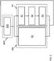
- FIG. 1schematically shows a hot beverage dispensing device 1.
- the devicecomprises at least one water inlet 11, a hot beverage preparation module 2 located downstream of the water inlet, and a beverage outlet 26 located downstream of the beverage preparation module for delivery of a prepared beverage to a receptacle in a first operational mode M0 of the device.
- the preparation and delivery of a hot beverageis schematically indicated as a step S0 in FIG. 2 .
- step S0involves a plurality of substeps known as such to the skilled person.
- the hot beverage dispensing devicefurther comprises a cleaning module 30.
- the cleansing module 30subsequently performs a first rinsing step S1, a treatment step S2 and a second rinsing step S3 as shown in FIG. 2 .
- the first rinsing step S1at least part of the beverage preparation module and the beverage outlet is rinsed with a rinsing fluid having a first rinsing fluid temperature.
- the treatment step S2at least part of the beverage preparation module 2 and the beverage outlet 26 is treated with a treatment fluid having a temperature that is higher than the first rinsing fluid temperature.
- the deviceIn the second rinsing step S3 at least part of the beverage preparation module 2 and the beverage outlet 26 is rinsed with a rinsing fluid having a second rinsing fluid temperature.
- the deviceassumes a standby mode M00, wherein it waits S00 for preparation instructions, for example, as provided from a user interface 18, for example a graphical user interface.
- the rinsing fluid as used in the first rinsing stepmay be water, or another fluid like air, or a combination thereof at a relatively low temperature, e.g. in a range of 10 to 40 degrees °C.
- the first rinsing stepsubstantially flushes any milk and/or coffee residues from the rinsed parts of the device and the outlet 26.
- rinsing with lukewarm water having a temperature in the range of 35 to 40 degrees °Csubstantially dissolves fats present in these parts, while avoiding a solidification of proteins.
- the used rinsing fluid leaving the outlet 26is typically collected and drained away.
- the relevant partsare treated with a treatment fluid having a temperature that is higher than the first rinsing fluid temperature.
- the temperature of the treatment fluidmay be at least 50 °C and preferably at least 60 °C.
- the treatment of the treatment fluid in this second stepis very effective, due to its relatively high temperature, while solidification of proteins is prevented due to their removal during the first step.
- the treatment fluidmay be water that is provided with an active ingredient, for example an antibacterial agent and/or a descaling substance. Also, other treatment fluids, such as alcohol may be considered for this purpose.
- the treatment fluid leaving the beverage outletmay be collected and re used.
- the collected rinsing fluidmay, for example, pass through a filter before it is re used to filter out contaminants present therein.
- the relevant partsare rinsed with a rinsing fluid having a second rinsing fluid temperature.
- any ingredients used during the treatment step S2are flushed out through the outlet.
- Cold wateris typically used in this step, which cools down the relevant part of the device for normal operation. Generally, fresh tap water is suitable for this purpose.
- an inlet filermay be applied, or the rinsing fluid may be provided from a separate source.
- the hot beverage dispensing device 1comprises a hot beverage preparation module 2 having a hot water supply section 20 to supply hot water, an ingredient supply section 22 to supply one or more ingredients, and a combining section 24 to prepare a hot beverage from the supplied hot water and the supplied one or more ingredients.
- the hot beverage as prepared in a first operational modeis supplied via the outlet 26 to a receptacle (not shown).
- the hot water supply section 20includes an inlet valve 201, a water reservoir 202, a pump 203, a flow meter 204 and a boiler 205 downstream of the inlet 11. These parts may be controllable by a controller 12 as shown in FIG. 1 , and/or may provide output signals to the controller 12.
- ingredient supply section 22includes a first ingredient supply element 221 to supply coffee, and a second ingredient supply element 222 to supply milk. It will be understood that in practice further ingredient supply elements may be present, for example for the supply of hot chocolate or soup.
- the combining section 24comprises combining elements 241/2, here in the form of water jet mixers for mixing the supplied ingredients with water.
- the cleaning module 30comprises an inlet valve 301, a reservoir 302, an inlet filter 303, a pump 305, a heater 306, a conductivity sensor 307, and a temperature sensor 308 downstream of a water inlet 300. It is noted that these elements may also be provided in another order.
- the pump 305is arranged downstream of the reservoir 302.
- the cleaning module 30further comprises a treatment agent dispenser 304 to dispense a treatment agent in the water reservoir, for example, a descaling agent, an anti-bacterial agent, or a detergent.
- the cleansing module 30has an outlet 310 to provide the rinsing, or treatment fluid to the hot beverage preparation module 2 and an inlet 311 to receive collected rinsing or treatment fluid from the hot beverage preparation module 2.
- the cleaning module 30further includes a multi-way valve 309 to direct returned fluid to either the reservoir 302, or towards a drain outlet 313.
- An additional inlet 312is provided to receive rinsing, or treatment fluid from the hot water supply section 20 of the hot beverage preparation module 2.
- the cleaning module 30 and the hot beverage preparation module 2are coupled via interface 41.
- Conduit 42serves to conduct the treatment/rinsing fluid from outlet 310 to the interface 41.
- Inlet 311receives the collected treatment/rinsing fluid via conduit 46 from collector 44. The additional inlet is coupled via conduit 43 to interface 41.
- a flow of rinsing/treatment fluid between the cleaning module 30 and the hot beverage preparation module 2is controlled by controllable valves 411, 412, 413, as well as by the controllable multiway valve 309.
- the hot water supply section 20is further provided with a first and a second one way valve 206, 207 at each side of the boiler 205.
- FIGS. 4A to 4COperation of the exemplary embodiment in the second mode is now described with reference to FIGS. 4A to 4C .
- a flow of rinsing/treatment fluidis schematically indicated with dashed arrows.
- Closed valves or other closed elementsare indicated with a cross (X).
- FIG. 4Aillustrates the first step S1 in more detail.
- the pump 305is activated to pump rinsing fluid from the reservoir 302 to the outlet 310 and via conduit 42 to the interface 41.
- the controllable valves 411 and 413are maintained in a closed position and only valve 412 is opened, so the rinsing fluid flows to the combining section 24.
- the first step S1comprises a first substep wherein controllable valve 243 is opened and controllable valve 244 is maintained in a closed position.
- controllable valve 244is opened and controllable valve 243 is maintained in a closed position.
- the combining elements 241, 242, shown here as waterjet mixersare rinsed in a more intensive manner than would be possible if both were rinsed at the same time.
- the multiway valve 309is set to re direct the rinsing fluid towards an outlet 313.
- the temperature of the rinsing fluidusually water, is for example in the range of 20 to 40 degrees °C.
- FIG. 4Bshows the second step S2 in more detail.
- the treatment fluidis guided via the conduit 42, via valve 412 to the combining unit 24 to the outlet 26.
- the treatment fluid leaving the outletis collected in tray 44 and returned via valve 309 to the reservoir 302.
- the valves 243, 244may be opened one at a time to provide for a more intensive cleansing of each of the water jet mixers 241, 242, and the associated outlets 26.
- a treatment agentfor example an anti-bacterial agent and/or a detergent may be released by treatment agent dosing device 304.
- the temperature of the treatment fluidis increased to a value that is higher than the rinsing fluid temperature in the first step S1, for example the treatment fluid may be increased to a value of at least 50 degrees °C, for example to 60 degrees °C.
- FIG. 4Cshows the third step S3 in more detail.
- the rinsing fluidmay be water, e.g. cold or lukewarm water, e.g. 20 to 40 degrees °C.
- multiway valve 309will be set to re direct the used rinsing fluid towards outlet 313.
- FIG. 5Ashows an optional descaling step S4.
- a treatment fluidtypically including a descaling agent is provided at outlet 310 via conduit 42 to the fluid interface 41.
- the supplied treatment fluidis redirected via valve 411 towards an inlet of the heater 205 and returned to an inlet 312 of the cleansing module via one-way valve 207, opened valve 413 and conduit 43.
- the treatment fluidis heated to a temperature above 80 degrees °C, preferably above 80 degrees °C, for example to 95 degrees °C.
- the treatment fluidis returned to the reservoir 302, it can be efficiently used with a relatively modest amount of electric energy.
- the presence of the descaling agent in the treatment fluidmay be verified from a reading of conductivity sensor 307, that is, the conductivity of the treatment fluid is increased by the presence of the descaling agent therein.
- FIG. 5Bshows a rinsing step S5 following the de scaling step S4.
- step S3the relevant parts of the hot beverage preparation module 2 are rinsed with cold or lukewarm water, in this case remove descaling agent from these parts.
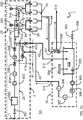
- FIG. 6schematically shows a further embodiment of a hot beverage preparation device 1 according to the present invention.
- the hot beverage preparation deviceis in particular suitable for preparation of foamed milk.
- the hot beverage preparation device of FIG. 6may, for example, be integrated with a hot beverage preparation device of FIG. 1 and/or FIG. 3 into a beverage preparation system.
- the device of FIG. 6comprises a water inlet 11, a hot beverage preparation module 2 located downstream of the water inlet, and a beverage outlet 26.
- the water inlet 11is coupled via an inlet valve 201 to a selection valve 509, a temperature sensor 508, a pump 507, a flow restriction 506, a heater 504 and a redirection valve 515 to an outlet 26.
- the devicealso includes a reservoir 222, e.g. for milk and a reservoir 302 for rinsing/treatment fluid.
- a second input of selection valve 509is coupled via a conductivity sensor 307 to an outlet of a further selection valve 512 having respective inputs coupled to each of the reservoirs 222, 302.
- the hot beverage dispensing device 1 of FIG. 6comprises a fluid transport trajectory 500 with at least one of a pump 507 and a heater 504. In FIG 6 both a pump and a heater are present..
- the deviceprovides an ingredient as a component of the hot beverage via the fluid transport trajectory to the beverage outlet 26. More in particular, in the first operational mode, the ingredient in reservoir 222, e.g. milk is pumped via valve 512 and via conductivity sensor to a first inlet of valve 509, while mixing the milk with water obtained from inlet 11 and air obtained from inlet 511 via controllable restriction 510.
- the mixtureis then guided via the temperature sensor 508, through the pump 507 and restriction 506 to heater 504 where it is heated to a desired temperature and dispensed at outlet 26.
- a second input of valve 512which is coupled to outlet 510 of reservoir 302 is closed and a second output of selection valve 515 which is coupled to inlet 511 of reservoir 302 is also closed.
- a flow of rinsing or treatment fluidis induced through the fluid transport trajectory 500. More specifically, selection valve 512 is set to selectively receive the rinsing/treatment fluid from the outlet 510 of the reservoir 302 which is provided to the fluid transport trajectory 500. Depending on the step performed in the second operational mode, the rinsing/treatment fluid may be either disposed at the outlet 26, or may be returned to the inlet 511 of the fluid reservoir.
- the fluid transport trajectory 500further includes a conductivity sensor 307 and a temperature sensor 508.
- a flow sensormay be included.
- the hot beverage dispensing device of FIG. 6includes a flow direction element 515 arranged upstream of the outlet 26which is configured to selectively redirect a flow of fluid streaming in a direction of the outlet 26 towards a rinsing/treatment fluid reservoir 302.
- a treatment fluidcan be circulated for a more efficient use with a treatment agent dissolved therein. Also energy consumption can be reduced therewith.
- a fluid capture element 518is provided. As schematically illustrated in FIG. 6A . the fluid capture element 518 is arranged downstream of the outlet 26.
- the hot beverage dispensing deviceis configured to selectively couple the fluid capture element 518 with the outlet 26 to capture fluid leaving the outlet and to redirect the fluid towards a rinsing/treatment fluid reservoir 302.
- a sealingmay be provided to avoid any fluid leakage between this coupling.
- FIG. 7shows a particular embodiment of a fluid capture element 518.
- the outlet 26comprises at least one outlet opening 261, 262 and at least one return opening 263 which is coupled to a drain conduit (for example towards the inlet 511 of reservoir 302, or to conduit 46 of FIG. 3 ).
- a drain conduitfor example towards the inlet 511 of reservoir 302, or to conduit 46 of FIG. 3 .
- the fluid capture element 518in this case has cavities 519, 520 that receive respective protrusions of the outlet 26 in the coupled state. It is a particular advantage of this embodiment that the rinsing/treatment liquid circulates in a turbulent manner around these protrusions, which also intensively cleans the outside of the protrusions.
- the first rinsing stepcomprises a sequence of substeps S101 to S113.
- the first treatment stepcomprises substeps S201 to S212 and the second rinsing step comprises S301 to S305.
- the purpose of each substepis summarized in the second column and the settings for the various elements is indicated in the subsequent columns.
- the value "0", "1"respectively indicates that the valve 201 is closed or opened.
- the value in column 507indicates the operation of the pump 507. A value 0 indicates that the pump is switched off, a value 1 indicates that it is operated at full capacity.
- a value between 0 and 1indicates that it is operated at the corresponding value of its capacity, for example 0.2 in state S103 indicates that it operates at 20% of its full capacity.
- Column 504indicates a temperature in degrees °C, set for the heater 504.
- a value 0means that the heater is switched off.
- Columns 509 and 512indicate a side A or B of the selected inlet.
- valve 509opens inlet A coupled to output of valve 201
- valve 512opens inlet B, coupled to the cleansing liquid reservoir 302.
- Column 515indicates the output of valve 515 to which the fluid is directed.
- “A”means output A towards reservoir 302 is selected and "B” means output B towards outlet 26 is selected.
- column 520indicates the setting of air valve 520: 0 is closed, 1 is open and 0/1 means that the valve is alternately opened and closed.
- STATE GOAL 201 507 504 509 512 515 520S101 Empty tubes 0 1 0 B B B 0 S102 Empty tubes 0 1 0 B B B 0 S103 Fill Reservoir 1 0,2 45 A B A 0 S104 Fill Reservoir 1 0,2 45 A B A 0 S106 Drain Reservoir 0 1 0 B B B 0 S107 Drain Reservoir 0 1 0 B B B 0 S113 Stop pre rinse 0 0 0 X X X 0 S201 Start heater 1 1 75 A B B 0 S202 Rinse Line 1 0,15 75 A B B 0 S203 Fill Reservoir 1 0,3 75 A B A 0 S204 Restart Heater 0 0,3 75 B B B 0 S205 Start Circulation 0 0,3 75 B B B 0 S206 Dispense Table 0 0
- substep S101 and S102 of the first rinsing stepfirst empty the fluid transport trajectory 500.
- the pump 507is activated at its full capacity to substantially remove remaining liquid from the trajectory 500.
- a conductivity valuemay be monitored with sensor 307, and an error message may be given if an unexpected value is measured. This may indicate an improper operation, for example indicating that no remainders of milk are detected.
- next substeps S103, A104the reservoir 302 is filled with tap water which is heated in the fluid transport trajectory 500 by heater 504.
- substeps S106 and S107the water is pumped from the reservoir 302 via the fluid transport trajectory 500 to outlet 26,to remove the contaminated rinsing liquid from the reservoir 302 and the fluid transport trajectory 500. Operation of the system is paused for a few seconds in substep S113, before preceding to the next sequence of substeps S201-S212.
- the reservoiris first filled with heated water in substeps S201-S203.
- substeps S204, S205the water is heated and circulated for some time until it reaches a desired temperature, e.g. at least 60 degrees °C.
- a treatment agentis dosed by treatment agent dosing device 304 in substep S206.
- the heater 504is reactivated (substep S207), additional water is supplied (S208) and when the treatment agent is dissolved therein, the treatment fluid is circulated through the fluid transport trajectory 500, valve 515 and reservoir 302 in substep S209.
- treatmentis intensified by periodically supplying air into the treatment fluid via valve 520. For example, every ten seconds, air is supplied for a period lasting a few seconds. For example, during circulation of the treatment fluid, air may be supplied every 20 seconds for a period of 4 seconds. This cycle may be repeated for a few times, e.g. 5 times.
- the reservoir 302is drained in substep S211 and the fluid transport trajectory 500 is drained in substep S212.
- valve 520is opened to allow the supplied air to expel a substantial amount of remaining fluids from the fluid transport trajectory 500.
- a second rinsing step S3follows with substeps S301-S305.
- the reservoiris filled with tap water.
- substep S302may be preceded by an additional reservoir draining substep S301.
- the reservoir 302is filled, it is drained via the fluid transport trajectory 500 and the rinsing fluid is disposed via outlet 26.
- further remaining fluidis disposed by allowing air to enter valve 520.
- a final substep S304proceeds to allow the device to cool down before proceeding further.
- FIG. 8shows sensor readings S C , S TH and S TL as obtained during the cleansing cycle as presented with reference to the table above.
- the left sideindicates the temperature scale for readings S TH and S TL in a range from 0 to 120 degrees °C.
- the right sideindicates a conductivity scale for the value S C extending from 0 to 700.
- a value 0indicates a relatively high conductivity and the value 700 indicates a relatively low conductivity.
- the horizontal axisindicates the time lapsed in seconds from the start of the cleaning cycle.
- FIG. 8for example demonstrates the rapid increase of conductivity after dosing the detergent in substep S206 and the fluctuations in rinsing fluid temperature measured during substep S201, when air is periodically added.
Landscapes
- Engineering & Computer Science (AREA)
- Food Science & Technology (AREA)
- Mechanical Engineering (AREA)
- Chemical & Material Sciences (AREA)
- Chemical Kinetics & Catalysis (AREA)
- General Chemical & Material Sciences (AREA)
- Apparatus For Making Beverages (AREA)
- Devices For Dispensing Beverages (AREA)
- Beverage Vending Machines With Cups, And Gas Or Electricity Vending Machines (AREA)
- Cleaning In General (AREA)
Description
- Hot beverage dispensing devices are commonly known that are capable of preparing a variety of hot beverages from water and one or more ingredients. A hot beverage dispensing device typically includes at least one water inlet, a hot beverage preparation module located downstream of the water inlet, and a beverage outlet downstream of the beverage preparation module. Such devices may for example prepare varieties of coffee, soup, hot milk, hot chocolate milk and the like. After each beverage dispensing action residues of ingredients remain in the device. Accordingly, it is important to regularly clean the device to avoid serious contaminations and potential food safety hazards.
EP2531085 discloses a hot beverage dispensing device that is provided with a cleaning arrangement. During a cleaning cycle, pressurized gas, e.g. a mixture of steam and air is passed through the various components of the device to remove such residues. In devices for dispensing a variety of beverages, this measure may not always be sufficient.- A further hot beverage dispensing device provided with a cleaning arrangement is disclosed in
EP-A-2869066 . - Accordingly, it is an object of the invention to provide an improved method for cleaning a hot beverage dispensing device, as well as a hot beverage dispensing device having an improved cleaning module.
- In accordance with the invention there is provided an improved method for cleaning a hot beverage dispensing device as claimed in
claim 1. - In accordance with the invention, there is further provided a hot beverage dispensing device having an improved cleaning module as claimed in
claim 12. - The improved method for cleaning a hot beverage dispensing device comprises a sequence of at least a first rinsing step, a treatment step and a second rinsing step.
- The first rinsing step comprises rinsing at least part of the beverage preparation module and the beverage outlet with a rinsing fluid having a first rinsing fluid temperature. The treatment step comprises treating at least part of the beverage preparation module and the beverage outlet with a treatment fluid. The treatment fluid has a temperature that is higher than the first rinsing fluid temperature. The second rinsing step comprises rinsing at least part of the beverage preparation module and the beverage outlet with a rinsing fluid having a second rinsing fluid temperature.
- In addition to the water inlet, hot beverage preparation module and beverage outlet referred to above which serve to deliver a prepared beverage to a receptacle in a first operational mode of the device, the improved hot beverage device further comprises a cleaning module. In a second operational mode of the device, the cleaning module subsequently performs a first rinsing step, a treatment step and a second rinsing step as specified above.
- The sequence of at least a first rinsing step, a treatment step and a second rinsing step as performed by the improved method, and as performed by the cleaning module in the second operational mode provide an improved cleaning of the device. This is most beneficial for applications where the hot beverage preparation device is used for preparation of a variety of different beverages.
- As a further improvement of the effectiveness of the treatment step, the treatment fluid may be provided with an active ingredient, for example, a detergent, an antibacterial agent and/or a descaling substance.
- Depending on the nature of the treatment step, a temperature of the treatment fluid is at least 50 °C, preferably at least 60 °C. Even higher temperatures may be set for a descaling step, for example at least 80 °C, preferably at least 90 °C. In one embodiment of the invention, at least one of the steps comprises the first rinsing step and the second rinsing step is carried out using cold or lukewarm water. Using cold, or preferably lukewarm water in the first rinsing step effectively removes at least a substantial amount of residue in the rinsed parts of the device, while avoiding a solidification of proteins. Using cold or lukewarm water in the second rinsing step cools down the rinsed parts of the system. A relatively fast cooling is achieved using cool rinsing water, however lukewarm water may alternatively be used, for example to mitigate against any risk of thermal shock, for example after a descaling treatment at high temperatures. The second rinsing step may further remove any residues of detergents, or other treatment agents if these were used during the treatment step.
- According to the invention treatment fluid leaves a beverage outlet and is collected and reused. This is advantageous in that an active ingredient can be used more effectively, and in that less energy is required to maintain the treatment fluid at the required temperature. It may also be contemplated to collect and reuse the rinsing fluid during the first and/or the second rinsing step. In that case, the collected rinsing and/or treatment fluid may, for example pass through a filter before it is reused to filter out contaminants present therein.
- In a further improved embodiment of the invention, a gas is introduced to the flow of rinsing fluid or the treatment fluid in a pulsating manner. In this way the effectiveness of the treatment is improved since the gas causes turbulence in the flow of rinsing fluid or the treatment fluid. Moreover, this is particularly advantageous for a treatment step requiring high temperatures. The air bubbles present in the flow locally allow for increased temperatures, for example in a heater element, so that, for example a descaling can be performed more effectively.
- In yet a further embodiment of the invention, the conductivity of a treatment fluid or rinsing fluid is measured in the second operational mode. In particular, the dispensing of an active ingredient into the fluid may be monitored using a value from the conductivity measurement. In this way it can effectively be verified at the onset of the treatment step that the active ingredient is present in the treatment fluid for proper execution of the treatment step. It can also be verified during the second rinsing step that the active ingredient is no longer present in the treated parts.
- A flow rate of the rinsing fluid, or the treatment fluid may be determined by measuring a difference in temperature of the respective rinsing fluid or treatment fluid at two positions in the machine. One position is located downstream of the heater and a second position is located upstream of the heater.. In this manner a separate flow meter is avoided and the temperature can be controlled according to the time available. In this way it is also possible to verify the correct functioning of a separate flow meter, if fitted.
- According to yet a further embodiment of the invention, a hot beverage preparation module of the hot beverage preparation device comprises a hot water supply section to supply hot water, an ingredient supply section to supply one or more ingredients, and a combining section to prepare a beverage from the supplied hot water and the supplied one or more ingredients to a beverage supply outlet for supply of the prepared beverage to a receptacle.
- A fluid interface may be provided between the cleaning module and the hot beverage preparation module. The fluid interface may comprise a flow redirection facility to selectively redirect a flow of rinsing/treatment fluid from the cleaning module upstream or downstream of a heater in the hot water supply section. The fluid interface with the redirection facility enables an efficient reuse of the cleaning device to descale the device.
- In an alternative embodiment of the invention, the hot beverage dispensing device comprises a fluid transport trajectory with at least one of a pump and a heater, wherein the device in its first operational mode provides an ingredient as a component of the hot beverage via the fluid transport trajectory to the beverage outlet, and wherein the device in its second operational mode induces a flow of rinsing or treatment fluid through the fluid transport trajectory. In this manner, parts of the hot beverage preparation device are efficiently reused for cleaning the device.
- The fluid transport trajectory may further comprise one or more sensors, such as a conductivity sensor, a flow sensor, or a temperature sensor. The sensor arranged in the fluid transport trajectory may be used for carrying out various measurements for performance verification during the first and the second operational mode.
- In yet a further embodiment of the improved hot beverage dispensing device, an inlet of the fluid transport trajectory is coupled via a selection valve to an ingredient reservoir for said ingredient and a rinsing/treatment fluid reservoir. In the first operational mode and the second operational mode, the selection valve respectively selects the ingredient reservoir and the rinsing/treatment fluid reservoir as inputs for the fluid transport trajectory. This allows for a rapid and efficient transition between the first and the second operational modes.
- It is noted that two or more embodiments of an improved beverage device as specified above may be combined into a beverage dispensing system.
- An improved hot beverage dispensing device may further comprise a flow direction element arranged upstream of the outlet, which is configured to selectively re direct a flow of fluid streaming in a direction of the outlet towards a rinsing/treatment fluid reservoir. In this way an effective circulation of rinsing/treatment fluid is achieved. Alternatively, rinsing/treatment may be collected at a collection tray.
- According to the invention a fluid capture element is provided that is arranged downstream of the outlet. Accordingly, the hot beverage dispensing device is configured to selectively couple the fluid capture element with the outlet to capture fluid leaving the outlet and to re direct the fluid towards a rinsing/treatment fluid reservoir. This is advantageous in that the rinsing/treatment fluid also rinses/treats the outlet, while providing a more effective re circulation than would be the case if the fluid is collected from a collection tray having a relatively large surface on which an amount of rinsing/treatment fluid could remain as droplets.
- The invention will now be described, by way of example only, with reference to the following drawings, in which:
FIG. 1 schematically illustrates an embodiment of a hot beverage preparation device according to the present invention,FIG. 2 schematically illustrates an embodiment of a method according to the present invention,FIG. 3 schematically illustrates a further embodiment of a hot beverage preparation device according to the present invention,FIG. 4A schematically illustrates a first step of an embodiment of a method according to the present invention performed in the device ofFIG. 4 ,FIG. 4B schematically illustrates a second step of an embodiment of a method according to the present invention performed in the device ofFIG. 4 ,FIG. 4C schematically illustrates a third step of an embodiment of a method according to the present invention performed in the device ofFIG. 4 ,FIG. 5A schematically illustrates a fourth step of an embodiment of a method according to the present invention performed in the device ofFIG. 4 ,FIG. 5B schematically illustrates a fifth step of an embodiment of a method according to the present invention performed in the device ofFIG. 4 ,FIG. 6 schematically illustratesFIG. 3 schematically illustrates a further embodiment of a hot beverage preparation device according to the present invention,FIG. 6A schematically illustrates a part of an alternative embodiment of a hot beverage preparation device according to the present invention,FIG. 7 illustrates an exemplary embodiment of the part ofFIG. 6A ,FIG. 8 shows various sensor readings obtained during operation of the device ofFIG. 6 in its second mode.FIG. 1 . schematically shows a hotbeverage dispensing device 1. The device comprises at least onewater inlet 11, a hotbeverage preparation module 2 located downstream of the water inlet, and abeverage outlet 26 located downstream of the beverage preparation module for delivery of a prepared beverage to a receptacle in a first operational mode M0 of the device. The preparation and delivery of a hot beverage is schematically indicated as a step S0 inFIG. 2 . In practice step S0 involves a plurality of substeps known as such to the skilled person. The hot beverage dispensing device further comprises acleaning module 30.- In a second operational mode M1 of the device, the cleansing
module 30 subsequently performs a first rinsing step S1, a treatment step S2 and a second rinsing step S3 as shown inFIG. 2 . In the first rinsing step S1 at least part of the beverage preparation module and the beverage outlet is rinsed with a rinsing fluid having a first rinsing fluid temperature. In the treatment step S2 at least part of thebeverage preparation module 2 and thebeverage outlet 26 is treated with a treatment fluid having a temperature that is higher than the first rinsing fluid temperature. In the second rinsing step S3 at least part of thebeverage preparation module 2 and thebeverage outlet 26 is rinsed with a rinsing fluid having a second rinsing fluid temperature. Upon completion, the device assumes a standby mode M00, wherein it waits S00 for preparation instructions, for example, as provided from auser interface 18, for example a graphical user interface. - The rinsing fluid as used in the first rinsing step may be water, or another fluid like air, or a combination thereof at a relatively low temperature, e.g. in a range of 10 to 40 degrees °C. The first rinsing step substantially flushes any milk and/or coffee residues from the rinsed parts of the device and the
outlet 26. In particular, rinsing with lukewarm water having a temperature in the range of 35 to 40 degrees °C substantially dissolves fats present in these parts, while avoiding a solidification of proteins. The used rinsing fluid leaving theoutlet 26 is typically collected and drained away. - In the second step S2, the relevant parts are treated with a treatment fluid having a temperature that is higher than the first rinsing fluid temperature. For example, the temperature of the treatment fluid may be at least 50 °C and preferably at least 60 °C. The treatment of the treatment fluid in this second step is very effective, due to its relatively high temperature, while solidification of proteins is prevented due to their removal during the first step. The treatment fluid may be water that is provided with an active ingredient, for example an antibacterial agent and/or a descaling substance. Also, other treatment fluids, such as alcohol may be considered for this purpose. In step S2, the treatment fluid leaving the beverage outlet may be collected and re used. This is advantageous in that an active ingredient can be used more effectively, and in that less energy is required to maintain the treatment fluid at the required temperature. It may also be contemplated to collect and re use the rinsing fluid in step S1. In that case, the collected rinsing fluid may, for example, pass through a filter before it is re used to filter out contaminants present therein.
- In the third step S3, the relevant parts are rinsed with a rinsing fluid having a second rinsing fluid temperature. In this step any ingredients used during the treatment step S2 are flushed out through the outlet. Cold water is typically used in this step, which cools down the relevant part of the device for normal operation. Generally, fresh tap water is suitable for this purpose. In some cases an inlet filer may be applied, or the rinsing fluid may be provided from a separate source. Also for this step S3 it may be contemplated to collect and re use the treatment fluid leaving the beverage outlet. For example, means may be provided that alternately allow an amount of rinsing fluid to circulate within the relevant parts and to flush rinsing fluid for replacement by a fresh amount of rinsing fluid.
- An example of an improved hot
beverage preparation device 1 is illustrated in more detail inFIG. 3 . The hotbeverage dispensing device 1 comprises a hotbeverage preparation module 2 having a hotwater supply section 20 to supply hot water, aningredient supply section 22 to supply one or more ingredients, and a combiningsection 24 to prepare a hot beverage from the supplied hot water and the supplied one or more ingredients. The hot beverage as prepared in a first operational mode is supplied via theoutlet 26 to a receptacle (not shown). - In the embodiment shown, the hot
water supply section 20 includes aninlet valve 201, awater reservoir 202, apump 203, aflow meter 204 and aboiler 205 downstream of theinlet 11. These parts may be controllable by acontroller 12 as shown inFIG. 1 , and/or may provide output signals to thecontroller 12. - In the exemplary embodiment shown in
FIG. 3 ,ingredient supply section 22 includes a firstingredient supply element 221 to supply coffee, and a secondingredient supply element 222 to supply milk. It will be understood that in practice further ingredient supply elements may be present, for example for the supply of hot chocolate or soup. - The combining
section 24 comprises combining elements 241/2, here in the form of water jet mixers for mixing the supplied ingredients with water. - In the embodiment shown in
FIG. 3 , thecleaning module 30 comprises aninlet valve 301, areservoir 302, aninlet filter 303, apump 305, aheater 306, aconductivity sensor 307, and atemperature sensor 308 downstream of awater inlet 300. It is noted that these elements may also be provided in another order. Preferably, however thepump 305 is arranged downstream of thereservoir 302. Thecleaning module 30 further comprises atreatment agent dispenser 304 to dispense a treatment agent in the water reservoir, for example, a descaling agent, an anti-bacterial agent, or a detergent. Thecleansing module 30 has anoutlet 310 to provide the rinsing, or treatment fluid to the hotbeverage preparation module 2 and aninlet 311 to receive collected rinsing or treatment fluid from the hotbeverage preparation module 2. Thecleaning module 30 further includes amulti-way valve 309 to direct returned fluid to either thereservoir 302, or towards adrain outlet 313. Anadditional inlet 312 is provided to receive rinsing, or treatment fluid from the hotwater supply section 20 of the hotbeverage preparation module 2. - In the embodiment shown the
cleaning module 30 and the hotbeverage preparation module 2 are coupled viainterface 41.Conduit 42 serves to conduct the treatment/rinsing fluid fromoutlet 310 to the interface 41.Inlet 311 receives the collected treatment/rinsing fluid viaconduit 46 fromcollector 44. The additional inlet is coupled viaconduit 43 tointerface 41. A flow of rinsing/treatment fluid between thecleaning module 30 and the hotbeverage preparation module 2 is controlled bycontrollable valves multiway valve 309. - In the embodiment shown the hot
water supply section 20 is further provided with a first and a second oneway valve boiler 205. - Operation of the exemplary embodiment in the second mode is now described with reference to
FIGS. 4A to 4C . Therein a flow of rinsing/treatment fluid is schematically indicated with dashed arrows. Closed valves or other closed elements are indicated with a cross (X). FIG. 4A illustrates the first step S1 in more detail. As shown inFIG. 4A , thepump 305 is activated to pump rinsing fluid from thereservoir 302 to theoutlet 310 and viaconduit 42 to theinterface 41. In this state, thecontrollable valves only valve 412 is opened, so the rinsing fluid flows to the combiningsection 24. In this case, the first step S1 comprises a first substep whereincontrollable valve 243 is opened andcontrollable valve 244 is maintained in a closed position. In a second substepcontrollable valve 244 is opened andcontrollable valve 243 is maintained in a closed position. In this way, the combining elements 241, 242, shown here as waterjet mixers are rinsed in a more intensive manner than would be possible if both were rinsed at the same time. Typically in this step, themultiway valve 309 is set to re direct the rinsing fluid towards anoutlet 313. The temperature of the rinsing fluid, usually water, is for example in the range of 20 to 40 degrees °C.FIG. 4B shows the second step S2 in more detail. In this step the treatment fluid is guided via theconduit 42, viavalve 412 to the combiningunit 24 to theoutlet 26. The treatment fluid leaving the outlet is collected intray 44 and returned viavalve 309 to thereservoir 302. Also in this step thevalves outlets 26. In this step S2 a treatment agent, for example an anti-bacterial agent and/or a detergent may be released by treatmentagent dosing device 304. In this step the temperature of the treatment fluid is increased to a value that is higher than the rinsing fluid temperature in the first step S1, for example the treatment fluid may be increased to a value of at least 50 degrees °C, for example to 60 degrees °C.FIG. 4C shows the third step S3 in more detail. As in the first step, the rinsing fluid may be water, e.g. cold or lukewarm water, e.g. 20 to 40 degrees °C. Typically,multiway valve 309 will be set to re direct the used rinsing fluid towardsoutlet 313.FIG. 5A shows an optional descaling step S4. In this step a treatment fluid, typically including a descaling agent is provided atoutlet 310 viaconduit 42 to thefluid interface 41. The supplied treatment fluid is redirected viavalve 411 towards an inlet of theheater 205 and returned to aninlet 312 of the cleansing module via one-way valve 207, openedvalve 413 andconduit 43. For best results the treatment fluid is heated to a temperature above 80 degrees °C, preferably above 80 degrees °C, for example to 95 degrees °C. As the treatment fluid is returned to thereservoir 302, it can be efficiently used with a relatively modest amount of electric energy. During the descaling step S4, the presence of the descaling agent in the treatment fluid may be verified from a reading ofconductivity sensor 307, that is, the conductivity of the treatment fluid is increased by the presence of the descaling agent therein.FIG. 5B shows a rinsing step S5 following the de scaling step S4. As in step S3, the relevant parts of the hotbeverage preparation module 2 are rinsed with cold or lukewarm water, in this case remove descaling agent from these parts.FIG. 6 schematically shows a further embodiment of a hotbeverage preparation device 1 according to the present invention. The hot beverage preparation device is in particular suitable for preparation of foamed milk. The hot beverage preparation device ofFIG. 6 may, for example, be integrated with a hot beverage preparation device ofFIG. 1 and/orFIG. 3 into a beverage preparation system.- The device of
FIG. 6 comprises awater inlet 11, a hotbeverage preparation module 2 located downstream of the water inlet, and abeverage outlet 26. Thewater inlet 11 is coupled via aninlet valve 201 to aselection valve 509, atemperature sensor 508, apump 507, aflow restriction 506, aheater 504 and aredirection valve 515 to anoutlet 26. The device also includes areservoir 222, e.g. for milk and areservoir 302 for rinsing/treatment fluid. A second input ofselection valve 509 is coupled via aconductivity sensor 307 to an outlet of afurther selection valve 512 having respective inputs coupled to each of thereservoirs - The hot
beverage dispensing device 1 ofFIG. 6 comprises afluid transport trajectory 500 with at least one of apump 507 and aheater 504. InFIG 6 both a pump and a heater are present.. In the first operational mode the device provides an ingredient as a component of the hot beverage via the fluid transport trajectory to thebeverage outlet 26. More in particular, in the first operational mode, the ingredient inreservoir 222, e.g. milk is pumped viavalve 512 and via conductivity sensor to a first inlet ofvalve 509, while mixing the milk with water obtained frominlet 11 and air obtained frominlet 511 viacontrollable restriction 510. The mixture is then guided via thetemperature sensor 508, through thepump 507 andrestriction 506 toheater 504 where it is heated to a desired temperature and dispensed atoutlet 26. In this mode, a second input ofvalve 512 which is coupled tooutlet 510 ofreservoir 302 is closed and a second output ofselection valve 515 which is coupled toinlet 511 ofreservoir 302 is also closed. - In the second operational mode of the device, a flow of rinsing or treatment fluid is induced through the
fluid transport trajectory 500. More specifically,selection valve 512 is set to selectively receive the rinsing/treatment fluid from theoutlet 510 of thereservoir 302 which is provided to thefluid transport trajectory 500. Depending on the step performed in the second operational mode, the rinsing/treatment fluid may be either disposed at theoutlet 26, or may be returned to theinlet 511 of the fluid reservoir. - In the embodiment shown the
fluid transport trajectory 500 further includes aconductivity sensor 307 and atemperature sensor 508. In an alternative arrangement, a flow sensor may be included. - As mentioned above, the hot beverage dispensing device of
FIG. 6 includes aflow direction element 515 arranged upstream of the outlet 26which is configured to selectively redirect a flow of fluid streaming in a direction of theoutlet 26 towards a rinsing/treatment fluid reservoir 302. In this way, for example, a treatment fluid can be circulated for a more efficient use with a treatment agent dissolved therein. Also energy consumption can be reduced therewith. - According to the invention, a
fluid capture element 518 is provided. As schematically illustrated inFIG. 6A . thefluid capture element 518 is arranged downstream of theoutlet 26. The hot beverage dispensing device is configured to selectively couple thefluid capture element 518 with theoutlet 26 to capture fluid leaving the outlet and to redirect the fluid towards a rinsing/treatment fluid reservoir 302. A sealing may be provided to avoid any fluid leakage between this coupling. FIG. 7 shows a particular embodiment of afluid capture element 518. In this embodiment theoutlet 26 comprises at least oneoutlet opening return opening 263 which is coupled to a drain conduit (for example towards theinlet 511 ofreservoir 302, or toconduit 46 ofFIG. 3 ). When thefluid capture element 518 is coupled with theoutlet 26 it causes the fluid to return via the return opening 263 to flow into the drain conduit. Thefluid capture element 518 in this case hascavities outlet 26 in the coupled state. It is a particular advantage of this embodiment that the rinsing/treatment liquid circulates in a turbulent manner around these protrusions, which also intensively cleans the outside of the protrusions.- An embodiment of the method according to the present invention as applied in the device of
FIG. 6 is now discussed with reference to the following Table. As indicated in the first column, the first rinsing step comprises a sequence of substeps S101 to S113. The first treatment step comprises substeps S201 to S212 and the second rinsing step comprises S301 to S305. The purpose of each substep is summarized in the second column and the settings for the various elements is indicated in the subsequent columns. In column "201" the value "0", "1" respectively indicates that thevalve 201 is closed or opened. The value incolumn 507 indicates the operation of thepump 507. Avalue 0 indicates that the pump is switched off, avalue 1 indicates that it is operated at full capacity. A value between 0 and 1 indicates that it is operated at the corresponding value of its capacity, for example 0.2 in state S103 indicates that it operates at 20% of its full capacity.Column 504 indicates a temperature in degrees °C, set for theheater 504. Avalue 0 means that the heater is switched off. Columns valve 509 opens inlet A coupled to output ofvalve 201, andvalve 512 opens inlet B, coupled to the cleansingliquid reservoir 302.Column 515 indicates the output ofvalve 515 to which the fluid is directed. "A" means output A towardsreservoir 302 is selected and "B" means output B towardsoutlet 26 is selected.- Finally,
column 520 indicates the setting of air valve 520: 0 is closed, 1 is open and 0/1 means that the valve is alternately opened and closed.STATE GOAL 201 507 504 509 512 515 520 S101 Empty tubes 0 1 0 B B B 0 S102 Empty tubes 0 1 0 B B B 0 S103 Fill Reservoir 1 0,2 45 A B A 0 S104 Fill Reservoir 1 0,2 45 A B A 0 S106 Drain Reservoir 0 1 0 B B B 0 S107 Drain Reservoir 0 1 0 B B B 0 S113 Stop pre rinse 0 0 0 X X X 0 S201 Start heater 1 1 75 A B B 0 S202 Rinse Line 1 0,15 75 A B B 0 S203 Fill Reservoir 1 0,3 75 A B A 0 S204 Restart Heater 0 0,3 75 B B B 0 S205 Start Circulation 0 0,3 75 B B B 0 S206 Dispense Table 0 0 0 X X X 0 S207 Start Heater 0 0 95 X X X 0 S208 Fill Reservoir 1 0,3 95 A B A 0 S209 Heat 80 0 0,3 95 B B A 0 S210 Circulation 0 1 95 B B A 0/1 S211 Drain reservoir 0 1 0 B B B 0 S212 Drain tubes 0 1 0 A B B 1 S301 Drain Reservoir 0 1 0 B B B 0 S302 Fill Reservoir 1 1 0 A B A 0 S303 Drain Reservoir 0 1 0 B B B 0 S304 Drain Tubes 0 1 0 B B B 1 S305 Wait for Tnorma 0 0 0 X X X 0 - In summary, by controlling the settings according to this table, the substeps S101 and S102 of the first rinsing step first empty the
fluid transport trajectory 500.. In substep S101, thepump 507 is activated at its full capacity to substantially remove remaining liquid from thetrajectory 500. A conductivity value may be monitored withsensor 307, and an error message may be given if an unexpected value is measured. This may indicate an improper operation, for example indicating that no remainders of milk are detected. - In the next substeps S103, A104 the
reservoir 302 is filled with tap water which is heated in thefluid transport trajectory 500 byheater 504. Subsequently in substeps S106 and S107, the water is pumped from thereservoir 302 via thefluid transport trajectory 500 tooutlet 26,to remove the contaminated rinsing liquid from thereservoir 302 and thefluid transport trajectory 500. Operation of the system is paused for a few seconds in substep S113, before preceding to the next sequence of substeps S201-S212. - In this subsequent series of substeps, i.e. substeps of a treatment step S2, the reservoir is first filled with heated water in substeps S201-S203. In substeps S204, S205 the water is heated and circulated for some time until it reaches a desired temperature, e.g. at least 60 degrees °C. After this temperature is achieved, a treatment agent is dosed by treatment
agent dosing device 304 in substep S206. Subsequently, theheater 504 is reactivated (substep S207), additional water is supplied (S208) and when the treatment agent is dissolved therein, the treatment fluid is circulated through thefluid transport trajectory 500,valve 515 andreservoir 302 in substep S209. - In substep S210 treatment is intensified by periodically supplying air into the treatment fluid via
valve 520. For example, every ten seconds, air is supplied for a period lasting a few seconds. For example, during circulation of the treatment fluid, air may be supplied every 20 seconds for a period of 4 seconds. This cycle may be repeated for a few times, e.g. 5 times. Upon completion of this treatment, thereservoir 302 is drained in substep S211 and thefluid transport trajectory 500 is drained in substep S212. Insubstep S212 valve 520 is opened to allow the supplied air to expel a substantial amount of remaining fluids from thefluid transport trajectory 500. - Subsequently a second rinsing step S3 follows with substeps S301-S305. In substep S302, the reservoir is filled with tap water. As an additional precaution substep S302 may be preceded by an additional reservoir draining substep S301. When the
reservoir 302 is filled, it is drained via thefluid transport trajectory 500 and the rinsing fluid is disposed viaoutlet 26. Subsequently, further remaining fluid is disposed by allowing air to entervalve 520. In this case a final substep S304 proceeds to allow the device to cool down before proceeding further. FIG. 8 shows sensor readings SC, STH and STL as obtained during the cleansing cycle as presented with reference to the table above. The left side indicates the temperature scale for readings STH and STL in a range from 0 to 120 degrees °C. The right side indicates a conductivity scale for the value SC extending from 0 to 700. Avalue 0 indicates a relatively high conductivity and thevalue 700 indicates a relatively low conductivity. The horizontal axis indicates the time lapsed in seconds from the start of the cleaning cycle.FIG. 8 for example demonstrates the rapid increase of conductivity after dosing the detergent in substep S206 and the fluctuations in rinsing fluid temperature measured during substep S201, when air is periodically added.
Claims (19)
- A method for cleaning a hot beverage dispensing device (1), the device comprising at least one water inlet (11), a hot beverage preparation module (2) located downstream of the water inlet and a beverage outlet (26) downstream of the beverage preparation module, the method including subsequently:
a first rinsing step (Si) of rinsing at least part of the beverage preparation module and the beverage outlet with a rinsing fluid having a first rinsing fluid temperature;- a treatment step (S2) of treating at least part of the beverage preparation module and the beverage outlet with a treatment fluid, the treatment fluid having a temperature that is higher than the first rinsing fluid temperature; and a second rinsing step (S3) of rinsing at least part of the beverage preparation module and the beverage outlet with a rinsing fluid having a second rinsing fluid temperature, wherein said treatment fluid leaves a beverage outlet and is collected and reused. - Method according to claim 1, wherein at least one of the first rinsing step (Si) and second rinsing step (S3), preferably both, is carried out using cold water.
- Method according to claim 1 or 2, wherein the treatment fluid is provided with an active ingredient, for example an antibacterial agent and/or a descaling substance.
- Method according to any of the preceding claims, wherein a temperature of the treatment fluid is at least 50 °C, for example at least 50 °C and preferably at least 60 °C.
- Method according to any of the preceding claims, wherein at least the beverage outlet (26) is cleaned by the rinsing steps (Si, S3) and treatment step (S2).
- Method according to any of the preceding claims, wherein the hot beverage preparation module (2) includes a water heater (20), wherein the method includes a water heater descaling process, including a water heater treatment step and a water heater rinsing step.
- Method according to any of the preceding claims, wherein a said rinsing fluid leaves a beverage outlet and is collected and reused.
- Method according to any of the preceding claims, including measuring a conductivity of said treatment fluid and/or said rinsing fluid.
- Method according to claim 8 wherein the conductivity measurement(s) are used to assess a level of active ingredient in the fluid(s).
- Method according to any preceding claim, wherein flow rate of the rinsing fluid or the treatment fluid is determined from a difference between a temperature of the rinsing fluid or the treatment fluid measured respectively at two positions, one position being downstream of the heater and a second position being up stream of the heater.
- Method according to any preceding claim, wherein a gas is added to the flow of rinsing fluid and/or flow of treatment fluid in a pulsating manner.
- A hot beverage dispensing device including at least one water inlet (11), a hot beverage preparation module (2) located downstream of the water inlet, a beverage outlet (21) located downstream of the beverage preparation module for delivery of a prepared beverage to a receptacle in a first operational mode of the device,characterized in that the beverage dispensing device further includes a cleansing module (30), which in a second operational mode of the device, subsequently performs a first rinsing step (Si), a treatment step (S2) and a second rinsing step (S3), wherein:the first rinsing step (Si) comprises rinsing at least part of the beverage preparation module and the beverage outlet with a rinsing fluid having a first rinsing fluid temperature;the treatment step (S2) comprises treating at least part of the beverage preparation module and the beverage outlet with a treatment fluid, the treatment fluid having a temperature that is higher than the first rinsing fluid temperature; and- the second rinsing step (S2) comprises rinsing at least part of the beverage preparation module and the beverage outlet with a rinsing fluid having a second rinsing fluid temperature, the beverage dispensing device further including a fluid capture element (518) arranged downstream with respect to the outlet (26), the beverage dispensing device being configured to selectively couple the fluid capture element (518) with the outlet (26) to capture fluid leaving the outlet and to redirect the fluid towards a rinsing/treatment fluid reservoir (302).
- The hot beverage dispensing device (1) according to claim 12, wherein the hot beverage preparation module (2) includes a hot water supply section (20) to supply hot water, an ingredient supply section (22) to supply one or more ingredients, and a combining section (24) to prepare a beverage from the supplied hot water and the supplied one or more ingredients to a beverage supply outlet (26) for supply of the prepared beverage to a receptacle (R).
- The hot beverage dispensing device (1) according to claim 13, wherein the hot beverage preparation module (2) includes a fluid interface (41) between the cleaning module (30) and the hot beverage preparation module (2), the fluid interface comprising a flow redirection facility (411, 412) to selectively redirect a flow of rinsing/treatment fluid from the cleaning module (30) upstream or downstream of a heater (205) in the hot water supply section (20).
- The hot beverage dispensing device (1) according to any one of claims 12 to 14, comprising a fluid transport trajectory (500) with at least one of a pump (507) and heater (504), wherein the device in its first operational mode provides an ingredient as a component of the hot beverage via the fluid transport trajectory to the beverage outlet (26), and wherein the device in its second operational mode induces a flow of rinsing or treatment fluid through the fluid transport trajectory (500).
- The hot beverage dispensing device (1) according to claim 15, wherein the fluid transport trajectory (500) further comprises at least one of a conductivity sensor (307), a flow sensor, or a temperature sensor (508).
- The hot beverage dispensing device (1) according to claim 15 or 16, wherein an inlet of the fluid transport trajectory (500) is coupled via a selection valve (512) to an ingredient reservoir (222) for said ingredient and to a rinsing/treatment fluid reservoir (302), wherein in said first operational mode and said second operational mode, the selection valve (512) respectively selects the ingredient reservoir (222) and the rinsing/treatment fluid reservoir (302) as input for the fluid transport trajectory (500).
- The hot beverage dispensing device (1) according to one of claims 12-17, further including a flow direction element (515) arranged upstream with respect to the outlet (26), which is configured to selectively redirect a flow of fluid streaming in a direction of the outlet (26) towards a rinsing/treatment fluid reservoir (302).
- The hot beverage dispensing device (1) according to any one of claims 12- 18, wherein the outlet (26) comprises at least one outlet opening (261, 262) and at least one return opening (263) coupled to a drain conduit, wherein the fluid capture element (518) when coupled with the outlet (26) causes the fluid to return via the return opening (263) to flow into the drain conduit.
Applications Claiming Priority (3)
| Application Number | Priority Date | Filing Date | Title |
|---|---|---|---|
| NL2018884ANL2018884B1 (en) | 2017-05-10 | 2017-05-10 | beverage brewing apparatus with nozzle exterior cleaning |
| NL2018886ANL2018886B1 (en) | 2017-05-10 | 2017-05-10 | Beverage dispensing device |
| PCT/NL2018/050308WO2018208157A1 (en) | 2017-05-10 | 2018-05-09 | Beverage dispensing device with cleaning module and method of cleaning said device |
Publications (2)
| Publication Number | Publication Date |
|---|---|
| EP3621498A1 EP3621498A1 (en) | 2020-03-18 |
| EP3621498B1true EP3621498B1 (en) | 2021-09-15 |
Family
ID=62167881
Family Applications (2)
| Application Number | Title | Priority Date | Filing Date |
|---|---|---|---|
| EP18725010.5AActiveEP3634186B1 (en) | 2017-05-10 | 2018-05-09 | Beverage brewing apparatus with nozzle exterior cleaning |
| EP18725011.3AActiveEP3621498B1 (en) | 2017-05-10 | 2018-05-09 | Beverage dispensing device with cleaning module and method of cleaning said device |
Family Applications Before (1)
| Application Number | Title | Priority Date | Filing Date |
|---|---|---|---|
| EP18725010.5AActiveEP3634186B1 (en) | 2017-05-10 | 2018-05-09 | Beverage brewing apparatus with nozzle exterior cleaning |
Country Status (12)
| Country | Link |
|---|---|
| US (2) | US12171363B2 (en) |
| EP (2) | EP3634186B1 (en) |
| JP (2) | JP7419071B2 (en) |
| KR (2) | KR102643769B1 (en) |
| CN (2) | CN110582216B (en) |
| AU (2) | AU2018266409B2 (en) |
| BR (2) | BR112019023584B1 (en) |
| CA (2) | CA3062584A1 (en) |
| DK (2) | DK3621498T3 (en) |
| ES (2) | ES2941960T3 (en) |
| RU (2) | RU2768259C2 (en) |
| WO (2) | WO2018208156A1 (en) |
Families Citing this family (15)
| Publication number | Priority date | Publication date | Assignee | Title |
|---|---|---|---|---|
| DE102017118598A1 (en)* | 2017-08-15 | 2019-02-21 | Franke Kaffeemaschinen Ag | DEVICE FOR PREPARING HOT BEVERAGES |
| KR102761380B1 (en)* | 2019-12-27 | 2025-01-31 | 후지 덴키 가부시키가이샤 | Beverage dispensing device |
| TWI739567B (en)* | 2020-08-25 | 2021-09-11 | 楓炫技研有限公司 | Drink extraction device |
| JP7655507B2 (en) | 2021-08-27 | 2025-04-02 | アサヒビール株式会社 | Cleaning device, method for using the cleaning device, and cleaning method |
| GB2610878B (en)* | 2021-09-21 | 2025-02-26 | Douwe Egberts Bv | An outlet nozzle arrangement for a drink dispensing apparatus |
| GB2610879B (en) | 2021-09-21 | 2024-10-16 | Douwe Egberts Bv | A mixing apparatus for a drink dispensing machine |
| ES2945233A1 (en)* | 2021-12-29 | 2023-06-29 | Cecotec Res And Development S L | CLEANING DEVICE FOR COFFEE MACHINE AND ITS ASSOCIATED METHOD (Machine-translation by Google Translate, not legally binding) |
| ES2945336A1 (en)* | 2021-12-31 | 2023-06-30 | Cecotec Res And Development S L | CLEANING SYSTEM OF THE STEAM ARM OF A COFFEE MAKER AND ASSOCIATED METHOD |
| WO2024015351A1 (en)* | 2022-07-11 | 2024-01-18 | Quality Mark, Inc. | Cleaning device for beverage dispenser nozzle |
| US20240245257A1 (en)* | 2023-01-20 | 2024-07-25 | Appliance Innovation, Inc. | Method and apparatus for brewing, mixing, and delivering a beverage |
| DE102023201354B3 (en)* | 2023-02-16 | 2024-07-18 | BSH Hausgeräte GmbH | Method for descaling a coffee machine and coffee machine and computer program product |
| GB2630788A (en) | 2023-06-08 | 2024-12-11 | Douwe Egberts Bv | Autonomous treatment process and apparatus |
| GB2632318A (en)* | 2023-08-02 | 2025-02-05 | Taphandles Llc | Beverage dispensing apparatus |
| US12369744B1 (en) | 2024-01-18 | 2025-07-29 | Sharkninja Operating Llc | Preparation of beverage machines for cold beverage brewing |
| WO2025155323A1 (en) | 2024-01-18 | 2025-07-24 | Sharkninja Operating Llc | Preventing coffee bean grinder jamming |
Family Cites Families (78)
| Publication number | Priority date | Publication date | Assignee | Title |
|---|---|---|---|---|
| US2535016A (en)* | 1947-12-26 | 1950-12-19 | Electric Auto Lite Co | Detachable coupling |
| US3390626A (en) | 1966-04-25 | 1968-07-02 | Universal Match Corp | Coffee vendor with cleaning system |
| JPS55132694A (en) | 1979-03-12 | 1980-10-15 | Kubota Ltd | Water treatment apparatus |
| KR830002140Y1 (en)* | 1980-06-24 | 1983-10-15 | 후지덴기 세이조오 가부시기 가이샤 | Water Supply System Cleaning Circuit in Beverage Vending Machine |
| JPS5714289U (en)* | 1980-06-24 | 1982-01-25 | ||
| JPS6029027Y2 (en)* | 1980-09-18 | 1985-09-03 | 富士電機株式会社 | Cleaning circuit for water supply system in cup-type beverage dispenser |
| JPH0789594A (en)* | 1993-09-17 | 1995-04-04 | Fuji Electric Co Ltd | Method for cleaning beverage circuit of beer dispenser |
| DE4411629A1 (en) | 1994-04-02 | 1995-11-02 | Tetra Laval Holdings & Finance | Valve for filling liquids in packaging |
| JPH0811992A (en)* | 1994-06-24 | 1996-01-16 | Suntory Ltd | Method and apparatus for cleaning tube-like passage |
| KR100379239B1 (en)* | 2001-02-16 | 2003-04-08 | (주)에코에이드 | Post mix type drink despenser with sterilizer |
| CN2525935Y (en)* | 2001-12-29 | 2002-12-18 | 马艺鸣 | Tableware washing machine |
| US6769627B2 (en)* | 2002-04-26 | 2004-08-03 | Nestec S.A. | Fluid dispensing device with self-cleaning nozzle and methods of use |
| EP1382281B1 (en) | 2002-07-19 | 2005-04-20 | Wmf Württembergische Metallwarenfabrik Ag | Apparatus and method for detecting the presence of cleaning agent in the cleaning water of a beverage vendor |
| US6889603B2 (en)* | 2002-12-24 | 2005-05-10 | Nestec S.A. | Clean-in-place automated food or beverage dispenser |
| AU2003903551A0 (en) | 2003-07-09 | 2003-07-24 | Muller Industries Australia Pty Ltd | System and method of cooling |
| DE102004006095A1 (en)* | 2004-02-06 | 2005-09-01 | Niro-Plan Ag | Device for producing milk foam |
| CH697020A5 (en) | 2004-04-13 | 2008-03-31 | Steiner Ag Weggis | Method and apparatus for producing milk foam or warm milk drinks. |
| JP4693430B2 (en)* | 2005-01-31 | 2011-06-01 | 三洋電機株式会社 | Beverage dispenser |
| US7562793B2 (en)* | 2005-02-08 | 2009-07-21 | Nestec S.A. | Dispensing device with self-cleaning nozzle |
| JP2008531162A (en)* | 2005-02-28 | 2008-08-14 | コーヒー ネーション リミテッド | Equipment for producing beverages |
| CN2815226Y (en)* | 2005-08-10 | 2006-09-13 | 于英霞 | Washing device of water-drinking bowl |
| EP1772081A1 (en)* | 2005-10-07 | 2007-04-11 | Cense d'Almez S.A. | Device for preparing an infused liquid |
| KR20070049703A (en)* | 2005-11-09 | 2007-05-14 | 삼성전자주식회사 | Nozzle cleaning device for applying photoresist |
| DE102006047969A1 (en)* | 2006-10-11 | 2008-04-17 | Niro-Plan Ag | Apparatus for preparing and dispensing beverages with a cleaning device |
| JP2008192047A (en) | 2007-02-07 | 2008-08-21 | Sanyo Electric Co Ltd | Beverage making apparatus |
| US8678239B2 (en) | 2007-07-13 | 2014-03-25 | The Coca-Cola Company | Clean in place system for beverage dispensers |
| EP2025268B1 (en)* | 2007-08-07 | 2009-07-29 | Gruppo Cimbali S.p.A. | Apparatus for washing circuits involved in the preparation of milk-based beverages |
| FR2929090B1 (en)* | 2008-03-26 | 2010-04-02 | Seb Sa | MACHINE FOR PREPARING BEVERAGES COMPRISING A SYSTEM FOR CLEANING A STEAM NOZZLE |
| GB2462278A (en)* | 2008-07-30 | 2010-02-03 | Waterwerkz Ltd | Sterilization of liquid dispensing apparatus using ozone |
| EP2272408A1 (en) | 2009-07-08 | 2011-01-12 | Jura Elektroapparate AG | Drink preparation machine and method for cleaning same |
| CN102028412A (en) | 2009-09-30 | 2011-04-27 | 曼尼托沃食品服务有限公司 | Multi-taste beverage distributing spray nozzle and distributor using same |
| EP2353474A1 (en) | 2010-02-03 | 2011-08-10 | Nestec S.A. | Beverage dispenser with safe cleaning arrangement |
| EP2353473A1 (en) | 2010-02-03 | 2011-08-10 | Nestec S.A. | Beverage dispenser with hygienic cleaning cycle |
| EP2364951A3 (en)* | 2010-03-09 | 2011-11-23 | Dominic Ellickson | A beverage dispensing gun cleaning apparatus |
| US9655985B2 (en)* | 2010-05-20 | 2017-05-23 | Automatic Bar Controls, Inc. | Ultraviolet disinfecting device for food and beverage dispensers |
| DE202010010509U1 (en)* | 2010-07-21 | 2011-10-05 | Franke Technology And Trademark Ltd. | Cleaning unit for a machine for the production of coffee mix drinks |
| CA2843759A1 (en)* | 2010-09-08 | 2012-03-15 | Scanomat A/S | A brewing device |
| JP5779884B2 (en) | 2011-01-11 | 2015-09-16 | 富士電機株式会社 | Beverage nozzle cleaning device |
| DE102011076214A1 (en) | 2011-05-20 | 2012-11-22 | Wmf Württembergische Metallwarenfabrik Ag | Vending Machine |
| DE102011077435A1 (en)* | 2011-06-10 | 2012-12-13 | Macchiavalley Produktions Gmbh | Cleaning system for hot drinks machines |
| US20130146109A1 (en)* | 2011-08-21 | 2013-06-13 | Ian Daniel Cavilia | In-place recirculatory draft beer line cleaning system |
| US9107538B2 (en)* | 2011-11-01 | 2015-08-18 | Pepsico, Inc. | Cold plasma sanitation for a dispensing machine |
| EP2594174B1 (en)* | 2011-11-18 | 2013-10-30 | Miele & Cie. KG | Beverage preparation machine |
| CN204797604U (en)* | 2011-12-02 | 2015-11-25 | Fbd合伙公司 | Food or drink dispensers, spout caps |
| CH706133A1 (en) | 2012-02-21 | 2013-08-30 | Schaerer Ag | Beverage preparation module with additional modules for self-service vending machines. |
| EP2638833A1 (en)* | 2012-03-16 | 2013-09-18 | Nestec S.A. | A beverage preparation machine with cleanable brewing head |
| DE102012104843A1 (en)* | 2012-06-05 | 2013-12-05 | Miele & Cie. Kg | Method for protecting fluid flow line system of beverage dispenser e.g. coffee machine, involves performing final rinsing of flow line system with fresh water by opening removal devices assigned to valves of fluid line system |
| JP6233315B2 (en)* | 2012-11-16 | 2017-11-22 | 大日本印刷株式会社 | Purification method for beverage filling device |
| US20140251994A1 (en)* | 2013-03-10 | 2014-09-11 | Intercon Chemical Company | Device for providing treatment to a fountain drink dispenser |
| JP2014184357A (en)* | 2013-03-21 | 2014-10-02 | Toshiba Corp | Nozzle cleaning unit and nozzle cleaning method |
| CH707837A1 (en) | 2013-03-26 | 2014-09-30 | Schaerer Ag | Vending Machine and method for operating such a vending machine. |
| DE102013112130A1 (en)* | 2013-11-05 | 2015-05-07 | Melitta Professional Coffee Solutions GmbH & Co. KG | Process for the detection of cleaning agents in a beverage machine, in particular a coffee machine |
| WO2015077237A2 (en)* | 2013-11-20 | 2015-05-28 | Starbucks Corporation D/B/A Starbucks Coffee Company | Cooking system power management |
| US9434594B2 (en)* | 2013-12-16 | 2016-09-06 | Panasonic Intellectual Property Management Co., Ltd. | Beverage dispenser |
| EP2918201A1 (en)* | 2014-03-13 | 2015-09-16 | Jura Elektroapparate Ag | Method for cleaning and/or disinfecting a milk- conveying system of a coffee machine and coffee machine |
| AU2015202474A1 (en) | 2014-05-09 | 2015-11-26 | Sunbeam Corporation Pty Ltd | Beverage maker with steam wand |
| DE102014216534B3 (en)* | 2014-08-20 | 2016-02-18 | Franke Kaffeemaschinen Ag | Apparatus and method for frothing a liquid food, in particular milk |
| ES2711854T3 (en) | 2014-09-04 | 2019-05-07 | Nestec Sa | A beverage preparation machine |
| DE102014112756A1 (en)* | 2014-09-04 | 2016-03-10 | Miele & Cie. Kg | A method of cleaning a milk-carrying flowline system of a beverage vending machine and vending machine for performing the method |
| CN106031919B (en) | 2014-10-16 | 2018-07-17 | 富士电机株式会社 | The cleaning device of the multi-way valve of beverage feeder |
| DE102015104146A1 (en)* | 2015-03-19 | 2016-09-22 | Air-Eltec Patent Ug (Haftungsbeschränkt) | Cleaning device and method for its operation |
| DE102015108438A1 (en) | 2015-05-28 | 2016-12-01 | Bwt Ag | Device for cleaning machines for the production of hot drinks, machine equipped therewith and method for its cleaning |
| AU2016274559B2 (en)* | 2015-06-09 | 2021-04-15 | Plae 2 Tech Ab | Brewing system and process of brewing a beverage |
| EP3114972B1 (en)* | 2015-07-09 | 2017-08-23 | Qbo Coffee GmbH | Beverage preparation machine |
| US10531761B2 (en)* | 2015-09-18 | 2020-01-14 | Starbucks Corporation | Beverage preparation systems and methods |
| CN105795910A (en)* | 2015-12-03 | 2016-07-27 | 深圳市易安诺科技有限公司 | Water dispenser pipeline cleaning method and water dispenser |
| KR102218579B1 (en)* | 2015-12-08 | 2021-02-22 | 후지 덴키 가부시키가이샤 | Drink dispensing apparatus |
| DE102016100715B4 (en)* | 2016-01-18 | 2025-09-04 | Miele & Cie. Kg | Hot drink maker with automatic cleaning device |
| CN107400586B (en)* | 2016-05-18 | 2021-05-28 | Lg电子株式会社 | Beer brewing device |
| CN105996765B (en)* | 2016-06-30 | 2019-10-22 | 珠海格力电器股份有限公司 | A direct drinking machine and its sterilization method |
| CN106419549B (en)* | 2016-09-26 | 2019-04-19 | 海南立昇净水科技实业有限公司 | Water dispenser |
| CN106419553A (en)* | 2016-10-20 | 2017-02-22 | 余伯坚 | Electric water boiler with scale removal function |
| US10272476B2 (en)* | 2016-10-21 | 2019-04-30 | Sea Hawk Systems, LLC | Method of delivering insecticide |
| WO2018081117A1 (en)* | 2016-10-25 | 2018-05-03 | Cornelius, Inc. | Systems of food dispenser cleaning |
| CN106510472A (en)* | 2017-01-10 | 2017-03-22 | 苏州咖博士咖啡系统科技有限公司 | Milk foam cleaning water route |
| US10357794B2 (en)* | 2017-03-29 | 2019-07-23 | The Boeing Company | Methods for removing residue from a nozzle |
| DE102017206767A1 (en)* | 2017-04-21 | 2018-10-25 | Wmf Group Gmbh | Milk delivery device and method for supplying milk |
| US10405693B2 (en)* | 2017-05-17 | 2019-09-10 | H&G Engineering Llc | Apparatus for manufacturing drink |
- 2018
- 2018-05-09ESES18725010Tpatent/ES2941960T3/enactiveActive
- 2018-05-09CNCN201880029683.XApatent/CN110582216B/enactiveActive
- 2018-05-09AUAU2018266409Apatent/AU2018266409B2/enactiveActive
- 2018-05-09USUS16/612,348patent/US12171363B2/enactiveActive
- 2018-05-09DKDK18725011.3Tpatent/DK3621498T3/enactive
- 2018-05-09EPEP18725010.5Apatent/EP3634186B1/enactiveActive
- 2018-05-09BRBR112019023584-1Apatent/BR112019023584B1/enactiveIP Right Grant
- 2018-05-09CNCN201880030472.8Apatent/CN110612049A/enactivePending
- 2018-05-09ESES18725011Tpatent/ES2893881T3/enactiveActive
- 2018-05-09EPEP18725011.3Apatent/EP3621498B1/enactiveActive
- 2018-05-09WOPCT/NL2018/050307patent/WO2018208156A1/ennot_activeCeased
- 2018-05-09KRKR1020197032771Apatent/KR102643769B1/enactiveActive
- 2018-05-09JPJP2019561298Apatent/JP7419071B2/enactiveActive
- 2018-05-09RURU2019139926Apatent/RU2768259C2/enactive
- 2018-05-09CACA3062584Apatent/CA3062584A1/enactivePending
- 2018-05-09RURU2019139927Apatent/RU2768328C2/enactive
- 2018-05-09USUS16/612,346patent/US11779152B2/enactiveActive
- 2018-05-09WOPCT/NL2018/050308patent/WO2018208157A1/ennot_activeCeased
- 2018-05-09BRBR112019023583-3Apatent/BR112019023583B1/enactiveIP Right Grant
- 2018-05-09DKDK18725010.5Tpatent/DK3634186T3/enactive
- 2018-05-09CACA3062564Apatent/CA3062564A1/enactivePending
- 2018-05-09AUAU2018266410Apatent/AU2018266410B2/enactiveActive
- 2018-05-09KRKR1020197032664Apatent/KR102535982B1/enactiveActive
- 2018-05-09JPJP2019561261Apatent/JP7602867B2/enactiveActive
Also Published As
Similar Documents
| Publication | Publication Date | Title |
|---|---|---|
| EP3621498B1 (en) | Beverage dispensing device with cleaning module and method of cleaning said device | |
| KR102340032B1 (en) | Assemblies and methods for processing fluids | |
| JP6362960B2 (en) | coffee maker | |
| KR102579083B1 (en) | Espresso coffee machine with system for cleaning the coffee dispensing system | |
| CN110461759B (en) | Device for filling container with filling product | |
| KR101296777B1 (en) | Clean water storage tank with a steam convection oven | |
| EP2108299A2 (en) | Programming machine with waste water reclaim | |
| CA2671813A1 (en) | Warewasher with water energy recovery system | |
| EP3269885A1 (en) | New-type cleaning device and cleaning method thereof | |
| WO2018139341A1 (en) | Beverage supply apparatus | |
| KR101296774B1 (en) | Clean water storage tank with a steam convection oven | |
| EP2818089B1 (en) | Conveyor type dishwasher machine | |
| KR101828030B1 (en) | Heat exchanger washing apparatus and heat exchanger washing method using the same | |
| NL2018886B1 (en) | Beverage dispensing device | |
| JP2018149472A (en) | Cleaning device | |
| EP3364847B1 (en) | Warewasher idling system and method | |
| JP4115525B2 (en) | Milk tank cleaning method and storage facility for performing the method | |
| EP3424400B1 (en) | Operating method of a professional tunnel dishwashing machine | |
| JPH1099222A (en) | Sanitizing cleaner of bathtub | |
| JPH11128624A (en) | Circulation warm bath device |
Legal Events
| Date | Code | Title | Description |
|---|---|---|---|
| STAA | Information on the status of an ep patent application or granted ep patent | Free format text:STATUS: UNKNOWN | |
| STAA | Information on the status of an ep patent application or granted ep patent | Free format text:STATUS: THE INTERNATIONAL PUBLICATION HAS BEEN MADE | |
| PUAI | Public reference made under article 153(3) epc to a published international application that has entered the european phase | Free format text:ORIGINAL CODE: 0009012 | |
| STAA | Information on the status of an ep patent application or granted ep patent | Free format text:STATUS: REQUEST FOR EXAMINATION WAS MADE | |
| 17P | Request for examination filed | Effective date:20191119 | |
| AK | Designated contracting states | Kind code of ref document:A1 Designated state(s):AL AT BE BG CH CY CZ DE DK EE ES FI FR GB GR HR HU IE IS IT LI LT LU LV MC MK MT NL NO PL PT RO RS SE SI SK SM TR | |
| AX | Request for extension of the european patent | Extension state:BA ME | |
| DAV | Request for validation of the european patent (deleted) | ||
| DAX | Request for extension of the european patent (deleted) | ||
| GRAP | Despatch of communication of intention to grant a patent | Free format text:ORIGINAL CODE: EPIDOSNIGR1 | |
| STAA | Information on the status of an ep patent application or granted ep patent | Free format text:STATUS: GRANT OF PATENT IS INTENDED | |
| INTG | Intention to grant announced | Effective date:20201215 | |
| GRAJ | Information related to disapproval of communication of intention to grant by the applicant or resumption of examination proceedings by the epo deleted | Free format text:ORIGINAL CODE: EPIDOSDIGR1 | |
| STAA | Information on the status of an ep patent application or granted ep patent | Free format text:STATUS: REQUEST FOR EXAMINATION WAS MADE | |
| GRAP | Despatch of communication of intention to grant a patent | Free format text:ORIGINAL CODE: EPIDOSNIGR1 | |
| STAA | Information on the status of an ep patent application or granted ep patent | Free format text:STATUS: GRANT OF PATENT IS INTENDED | |
| INTC | Intention to grant announced (deleted) | ||
| INTG | Intention to grant announced | Effective date:20210414 | |
| GRAS | Grant fee paid | Free format text:ORIGINAL CODE: EPIDOSNIGR3 | |
| GRAA | (expected) grant | Free format text:ORIGINAL CODE: 0009210 | |
| STAA | Information on the status of an ep patent application or granted ep patent | Free format text:STATUS: THE PATENT HAS BEEN GRANTED | |
| AK | Designated contracting states | Kind code of ref document:B1 Designated state(s):AL AT BE BG CH CY CZ DE DK EE ES FI FR GB GR HR HU IE IS IT LI LT LU LV MC MK MT NL NO PL PT RO RS SE SI SK SM TR | |
| REG | Reference to a national code | Ref country code:CH Ref legal event code:EP | |
| REG | Reference to a national code | Ref country code:DE Ref legal event code:R096 Ref document number:602018023596 Country of ref document:DE | |
| REG | Reference to a national code | Ref country code:DK Ref legal event code:T3 Effective date:20211004 | |
| REG | Reference to a national code | Ref country code:IE Ref legal event code:FG4D | |
| REG | Reference to a national code | Ref country code:AT Ref legal event code:REF Ref document number:1429852 Country of ref document:AT Kind code of ref document:T Effective date:20211015 | |
| REG | Reference to a national code | Ref country code:NL Ref legal event code:FP | |
| REG | Reference to a national code | Ref country code:SE Ref legal event code:TRGR | |
| REG | Reference to a national code | Ref country code:NO Ref legal event code:T2 Effective date:20210915 Ref country code:LT Ref legal event code:MG9D | |
| PG25 | Lapsed in a contracting state [announced via postgrant information from national office to epo] | Ref country code:BG Free format text:LAPSE BECAUSE OF FAILURE TO SUBMIT A TRANSLATION OF THE DESCRIPTION OR TO PAY THE FEE WITHIN THE PRESCRIBED TIME-LIMIT Effective date:20211215 Ref country code:LT Free format text:LAPSE BECAUSE OF FAILURE TO SUBMIT A TRANSLATION OF THE DESCRIPTION OR TO PAY THE FEE WITHIN THE PRESCRIBED TIME-LIMIT Effective date:20210915 Ref country code:FI Free format text:LAPSE BECAUSE OF FAILURE TO SUBMIT A TRANSLATION OF THE DESCRIPTION OR TO PAY THE FEE WITHIN THE PRESCRIBED TIME-LIMIT Effective date:20210915 Ref country code:HR Free format text:LAPSE BECAUSE OF FAILURE TO SUBMIT A TRANSLATION OF THE DESCRIPTION OR TO PAY THE FEE WITHIN THE PRESCRIBED TIME-LIMIT Effective date:20210915 Ref country code:RS Free format text:LAPSE BECAUSE OF FAILURE TO SUBMIT A TRANSLATION OF THE DESCRIPTION OR TO PAY THE FEE WITHIN THE PRESCRIBED TIME-LIMIT Effective date:20210915 | |
| REG | Reference to a national code | Ref country code:ES Ref legal event code:FG2A Ref document number:2893881 Country of ref document:ES Kind code of ref document:T3 Effective date:20220210 | |
| REG | Reference to a national code | Ref country code:AT Ref legal event code:MK05 Ref document number:1429852 Country of ref document:AT Kind code of ref document:T Effective date:20210915 | |
| PG25 | Lapsed in a contracting state [announced via postgrant information from national office to epo] | Ref country code:LV Free format text:LAPSE BECAUSE OF FAILURE TO SUBMIT A TRANSLATION OF THE DESCRIPTION OR TO PAY THE FEE WITHIN THE PRESCRIBED TIME-LIMIT Effective date:20210915 Ref country code:GR Free format text:LAPSE BECAUSE OF FAILURE TO SUBMIT A TRANSLATION OF THE DESCRIPTION OR TO PAY THE FEE WITHIN THE PRESCRIBED TIME-LIMIT Effective date:20211216 | |
| PG25 | Lapsed in a contracting state [announced via postgrant information from national office to epo] | Ref country code:AT Free format text:LAPSE BECAUSE OF FAILURE TO SUBMIT A TRANSLATION OF THE DESCRIPTION OR TO PAY THE FEE WITHIN THE PRESCRIBED TIME-LIMIT Effective date:20210915 | |
| PG25 | Lapsed in a contracting state [announced via postgrant information from national office to epo] | Ref country code:IS Free format text:LAPSE BECAUSE OF FAILURE TO SUBMIT A TRANSLATION OF THE DESCRIPTION OR TO PAY THE FEE WITHIN THE PRESCRIBED TIME-LIMIT Effective date:20220115 Ref country code:SM Free format text:LAPSE BECAUSE OF FAILURE TO SUBMIT A TRANSLATION OF THE DESCRIPTION OR TO PAY THE FEE WITHIN THE PRESCRIBED TIME-LIMIT Effective date:20210915 Ref country code:SK Free format text:LAPSE BECAUSE OF FAILURE TO SUBMIT A TRANSLATION OF THE DESCRIPTION OR TO PAY THE FEE WITHIN THE PRESCRIBED TIME-LIMIT Effective date:20210915 Ref country code:RO Free format text:LAPSE BECAUSE OF FAILURE TO SUBMIT A TRANSLATION OF THE DESCRIPTION OR TO PAY THE FEE WITHIN THE PRESCRIBED TIME-LIMIT Effective date:20210915 Ref country code:PT Free format text:LAPSE BECAUSE OF FAILURE TO SUBMIT A TRANSLATION OF THE DESCRIPTION OR TO PAY THE FEE WITHIN THE PRESCRIBED TIME-LIMIT Effective date:20220117 Ref country code:PL Free format text:LAPSE BECAUSE OF FAILURE TO SUBMIT A TRANSLATION OF THE DESCRIPTION OR TO PAY THE FEE WITHIN THE PRESCRIBED TIME-LIMIT Effective date:20210915 Ref country code:EE Free format text:LAPSE BECAUSE OF FAILURE TO SUBMIT A TRANSLATION OF THE DESCRIPTION OR TO PAY THE FEE WITHIN THE PRESCRIBED TIME-LIMIT Effective date:20210915 Ref country code:CZ Free format text:LAPSE BECAUSE OF FAILURE TO SUBMIT A TRANSLATION OF THE DESCRIPTION OR TO PAY THE FEE WITHIN THE PRESCRIBED TIME-LIMIT Effective date:20210915 Ref country code:AL Free format text:LAPSE BECAUSE OF FAILURE TO SUBMIT A TRANSLATION OF THE DESCRIPTION OR TO PAY THE FEE WITHIN THE PRESCRIBED TIME-LIMIT Effective date:20210915 | |
| REG | Reference to a national code | Ref country code:DE Ref legal event code:R097 Ref document number:602018023596 Country of ref document:DE | |
| PLBE | No opposition filed within time limit | Free format text:ORIGINAL CODE: 0009261 | |
| STAA | Information on the status of an ep patent application or granted ep patent | Free format text:STATUS: NO OPPOSITION FILED WITHIN TIME LIMIT | |
| 26N | No opposition filed | Effective date:20220616 | |
| PG25 | Lapsed in a contracting state [announced via postgrant information from national office to epo] | Ref country code:SI Free format text:LAPSE BECAUSE OF FAILURE TO SUBMIT A TRANSLATION OF THE DESCRIPTION OR TO PAY THE FEE WITHIN THE PRESCRIBED TIME-LIMIT Effective date:20210915 | |
| PG25 | Lapsed in a contracting state [announced via postgrant information from national office to epo] | Ref country code:MC Free format text:LAPSE BECAUSE OF FAILURE TO SUBMIT A TRANSLATION OF THE DESCRIPTION OR TO PAY THE FEE WITHIN THE PRESCRIBED TIME-LIMIT Effective date:20210915 Ref country code:LU Free format text:LAPSE BECAUSE OF NON-PAYMENT OF DUE FEES Effective date:20220509 | |
| PG25 | Lapsed in a contracting state [announced via postgrant information from national office to epo] | Ref country code:IE Free format text:LAPSE BECAUSE OF NON-PAYMENT OF DUE FEES Effective date:20220509 | |
| P01 | Opt-out of the competence of the unified patent court (upc) registered | Effective date:20230505 | |
| PG25 | Lapsed in a contracting state [announced via postgrant information from national office to epo] | Ref country code:MK Free format text:LAPSE BECAUSE OF FAILURE TO SUBMIT A TRANSLATION OF THE DESCRIPTION OR TO PAY THE FEE WITHIN THE PRESCRIBED TIME-LIMIT Effective date:20210915 Ref country code:CY Free format text:LAPSE BECAUSE OF FAILURE TO SUBMIT A TRANSLATION OF THE DESCRIPTION OR TO PAY THE FEE WITHIN THE PRESCRIBED TIME-LIMIT Effective date:20210915 | |
| PG25 | Lapsed in a contracting state [announced via postgrant information from national office to epo] | Ref country code:HU Free format text:LAPSE BECAUSE OF FAILURE TO SUBMIT A TRANSLATION OF THE DESCRIPTION OR TO PAY THE FEE WITHIN THE PRESCRIBED TIME-LIMIT; INVALID AB INITIO Effective date:20180509 | |
| PG25 | Lapsed in a contracting state [announced via postgrant information from national office to epo] | Ref country code:TR Free format text:LAPSE BECAUSE OF FAILURE TO SUBMIT A TRANSLATION OF THE DESCRIPTION OR TO PAY THE FEE WITHIN THE PRESCRIBED TIME-LIMIT Effective date:20210915 | |
| PG25 | Lapsed in a contracting state [announced via postgrant information from national office to epo] | Ref country code:MT Free format text:LAPSE BECAUSE OF FAILURE TO SUBMIT A TRANSLATION OF THE DESCRIPTION OR TO PAY THE FEE WITHIN THE PRESCRIBED TIME-LIMIT Effective date:20210915 | |
| PGFP | Annual fee paid to national office [announced via postgrant information from national office to epo] | Ref country code:NL Payment date:20250526 Year of fee payment:8 | |
| PGFP | Annual fee paid to national office [announced via postgrant information from national office to epo] | Ref country code:DE Payment date:20250529 Year of fee payment:8 | |
| PGFP | Annual fee paid to national office [announced via postgrant information from national office to epo] | Ref country code:GB Payment date:20250527 Year of fee payment:8 Ref country code:ES Payment date:20250602 Year of fee payment:8 Ref country code:DK Payment date:20250526 Year of fee payment:8 | |
| PGFP | Annual fee paid to national office [announced via postgrant information from national office to epo] | Ref country code:NO Payment date:20250530 Year of fee payment:8 | |
| PGFP | Annual fee paid to national office [announced via postgrant information from national office to epo] | Ref country code:IT Payment date:20250521 Year of fee payment:8 Ref country code:BE Payment date:20250527 Year of fee payment:8 | |
| PGFP | Annual fee paid to national office [announced via postgrant information from national office to epo] | Ref country code:FR Payment date:20250526 Year of fee payment:8 | |
| PGFP | Annual fee paid to national office [announced via postgrant information from national office to epo] | Ref country code:CH Payment date:20250601 Year of fee payment:8 | |
| PGFP | Annual fee paid to national office [announced via postgrant information from national office to epo] | Ref country code:SE Payment date:20250527 Year of fee payment:8 |