EP3620265B1 - Tool system - Google Patents
Tool systemDownload PDFInfo
- Publication number
- EP3620265B1 EP3620265B1EP19193756.4AEP19193756AEP3620265B1EP 3620265 B1EP3620265 B1EP 3620265B1EP 19193756 AEP19193756 AEP 19193756AEP 3620265 B1EP3620265 B1EP 3620265B1
- Authority
- EP
- European Patent Office
- Prior art keywords
- tool
- driver
- overload
- sensing unit
- type
- Prior art date
- Legal status (The legal status is an assumption and is not a legal conclusion. Google has not performed a legal analysis and makes no representation as to the accuracy of the status listed.)
- Active
Links
Images


Classifications
- B—PERFORMING OPERATIONS; TRANSPORTING
- B25—HAND TOOLS; PORTABLE POWER-DRIVEN TOOLS; MANIPULATORS
- B25F—COMBINATION OR MULTI-PURPOSE TOOLS NOT OTHERWISE PROVIDED FOR; DETAILS OR COMPONENTS OF PORTABLE POWER-DRIVEN TOOLS NOT PARTICULARLY RELATED TO THE OPERATIONS PERFORMED AND NOT OTHERWISE PROVIDED FOR
- B25F3/00—Associations of tools for different working operations with one portable power-drive means; Adapters therefor
- B—PERFORMING OPERATIONS; TRANSPORTING
- B25—HAND TOOLS; PORTABLE POWER-DRIVEN TOOLS; MANIPULATORS
- B25F—COMBINATION OR MULTI-PURPOSE TOOLS NOT OTHERWISE PROVIDED FOR; DETAILS OR COMPONENTS OF PORTABLE POWER-DRIVEN TOOLS NOT PARTICULARLY RELATED TO THE OPERATIONS PERFORMED AND NOT OTHERWISE PROVIDED FOR
- B25F5/00—Details or components of portable power-driven tools not particularly related to the operations performed and not otherwise provided for
- B25F5/001—Gearings, speed selectors, clutches or the like specially adapted for rotary tools
- B—PERFORMING OPERATIONS; TRANSPORTING
- B25—HAND TOOLS; PORTABLE POWER-DRIVEN TOOLS; MANIPULATORS
- B25F—COMBINATION OR MULTI-PURPOSE TOOLS NOT OTHERWISE PROVIDED FOR; DETAILS OR COMPONENTS OF PORTABLE POWER-DRIVEN TOOLS NOT PARTICULARLY RELATED TO THE OPERATIONS PERFORMED AND NOT OTHERWISE PROVIDED FOR
- B25F5/00—Details or components of portable power-driven tools not particularly related to the operations performed and not otherwise provided for
- B25F5/02—Construction of casings, bodies or handles
- B—PERFORMING OPERATIONS; TRANSPORTING
- B23—MACHINE TOOLS; METAL-WORKING NOT OTHERWISE PROVIDED FOR
- B23D—PLANING; SLOTTING; SHEARING; BROACHING; SAWING; FILING; SCRAPING; LIKE OPERATIONS FOR WORKING METAL BY REMOVING MATERIAL, NOT OTHERWISE PROVIDED FOR
- B23D45/00—Sawing machines or sawing devices with circular saw blades or with friction saw discs
- B23D45/16—Hand-held sawing devices with circular saw blades
Definitions
- the present disclosuregenerally relates to power tool systems and specifically to a power tool system including a body to which a tool is attachable.
- Patent Literature 1JP 2009-534203 A discloses a handheld electric power tool.
- the handheld electric power toolincludes an electric motor configured to drive a driven member that grips a working element (e.g., an abrasive disc).
- a working elemente.g., an abrasive disc
- Document WO 2006/104929describes a power tool accessory identification system including a power tool which has a motor, an output spindle actuatable by the motor, and a tool holder connected to the spindle and configured to hold an accessory therein.
- the power toolincludes an accessory reader to decoding an identification device on the accessory.
- Document EP 1884325describes a device having a housing body and a grinding-cutting-scrubbing wheel mountable at the housing body.
- a toolhas a code, which is identifiable by a sensor unit at a housing body of the hand tool device in a contactless manner, where the sensor unit acts together with an electrical or electronic control device. Controlling measures are executable by the control device in dependent of the identification.
- the codecomprises of magnetic or magnetizable material.
- the sensor unitcomprises an electrical coil, which detects magnetic flux.
- a tool system according to an aspect of the present disclosureis defined in claim 1.
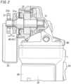
- FIGS. 1 and 2show a tool system 1 according to the present embodiment.
- the tool system 1is an electric power tool system.
- the tool system 1includes a body 20, a driver 30, and a tool sensing unit 40.
- the body 20is a grinder.
- the body 20is, for example, a portable electric power grinder or a handheld electric power grinder.
- a tool 10is attachable.
- the tool 10is separated from the body 20, and the tool 10 is attachable to and detachable from the body 20 as needed.
- the tool 10includes a cutting blade 11 and a grinding blade 12.
- the driver 30has a function of driving the tool 10 attached to the body 20. That is, the driver 30 gives power to the tool 10 attached to the body 20 to rotate or vibrate.
- the driver 30is, for example, a motor and gives power to the tool 10, thereby rotating the tool 10.
- the tool sensing unit 40has a function of identifying the type of the tool 10 attached to the body 20. That is, the tool sensing unit 40 identifies which type of a plurality of types the tool 10 corresponds to in a state where the tool 10 is attached to the body 20.
- the tool sensing unit 40is configured to identify the cutting blade 11 and the grinding blade 12. That is, the tool sensing unit 40 is configured to distinguish a plurality of types of tools 10 for different functions or usages.
- the tool system 1is configured to identify, with the tool sensing unit 40, the type of the tool 10 attached to the body 20. That is, the tool system 1 is configured to determine, before or during its use, which work the tool 10 attached to the body 20 supports. Thus, a worker using the tool system 1 easily recognizes the type of the tool 10 attached to the body 20 and is less likely to do work unsupported by the tool 10. This provides the advantage that a failure or breakage of the driver 30 caused due to incorrect use of the tool 10 is less likely to occur. This also provides the advantage that a failure or breakage of the tool 10 caused due to incorrect use of the tool 10 is less likely to occur.
- the tool system 1according to the present embodiment will be described in detail below.
- the tool system 1includes the body 20, the driver 30, and the tool sensing unit 40.
- the tool system 1may further include the tool 10. That is, the tool 10 is a component of the tool system 1.
- the tool 10does not necessarily have to be a component of the tool system 1. That is, the tool system 1 does not have to include the tool 10.
- the body 20includes a housing 22.
- the housing 22includes the tool sensing unit 40 and the driver 30. That is, the housing 22 accommodates the tool sensing unit 40 and the driver 30.
- the housing 22accommodates a controller 50, an overload sensor 60, a protector 70, a notification device 80, and a warning device 100.
- the housing 22is a tubular housing having such a thickness that the tubular housing can be grabbed with a single hand.
- the housing 22has one end (rear end) to which a battery pack 91 as a power supply 90 is attached.
- the battery pack 91is detachably attached to the housing 22.
- the housing 22has the other end (front end) whose lower surface is provided with a cover 23.
- the cover 23has a semicircular arc shape in bottom plan view, and the cover 23 protrudes rearward from the front end of the housing 22.
- the housing 22has an upper surface provided with a manipulation section 24.
- the manipulation section 24is configured to receive an operation given by a user to turn ON and OFF a switch.
- the manipulation section 24is manipulated to turn ON the switch, thereby allowing electric power to be supplied from the power supply 90 to the driver 30 so as to operate the driver 30.
- the manipulation section 24is manipulated to turn OFF the switch, thereby stopping supply of the electric power from the power supply 90 to the driver 30 so as to stop the operation of the driver 30.
- the upper surface of the housing 22is provided with the notification device 80.
- the notification device 80is configured to perform notification of an identification result by the tool sensing unit 40. That is, the notification device 80 is configured to perform notification of the type of the tool 10 identified by the tool sensing unit 40.
- the notification device 80includes, for example, a light-emitting element such as a light-emitting diode (LED). In this case, it is possible to cause the light-emitting element to emit light, extinguish light, change the color of emitting light, flash light, or change the flashing interval of light depending on the type of the tool 10 identified by the tool sensing unit 40.
- the notification device 80may be a liquid crystal display.
- the type of the tool 10 identified by the tool sensing unit 40is displayable as characters or symbols.
- the notification device 80may be configured to output a sound. In this case, depending on the type of the tool 10 identified by the tool sensing unit 40, the scale, volume, timbre, or the like of the sound is changeable with the notification device 80.
- the notification device 80may be configured to transmit a signal to an external apparatus. In this case, it is possible, depending on the type of the tool 10 identified by the tool sensing unit 40, to change the interval or timing of transmitting the signal from the notification device 80.
- the notification device 80is configured to notify a user or the like of the type of the tool 10 attached to the body 20.
- the driver 30has a function of driving the tool 10 attached to the body 20. That is, the driver 30 gives power to the tool 10 attached to the body 20 to rotate.
- the driver 30is a motor 32.
- a transmission mechanism 31is mechanically connected to the driver 30. That is, the motor 32 serving as the driver 30 has a rotary shaft to which the transmission mechanism 31 is mechanically connected.
- the transmission mechanism 31has a function of transmitting rotary driving force of the rotary shaft of the motor 32 to the tool 10.
- the transmission mechanism 31includes a gear, a bevel gear, an output shaft 33, and the like.
- the body 20includes an attachment 21 to which the tool 10 is to be attached.
- the attachment 21is provided at an end of the output shaft 33.
- the attachment 21includes a pair of ring members 21a and 21b provided at the end of the output shaft 33.
- the tool 10is attached to the output shaft 33 with the tool 10 being sandwiched in a thickness direction between the pair of ring members 21a and 21b. That is, in a state where one ring member 21a is attached to the output shaft 33, a tip of the output shaft 33 is inserted into a pore 10a formed in the tool 10, and then, the other ring member 21b is attached to the output shaft 33.
- the tool sensing unit 40has a function of identifying the type of the tool 10 attached to the body 20. That is, the tool sensing unit 40 has a function of performing checking to know the type of the tool 10 in a state where the tool 10 is attached to the output shaft 33. That is, the tool sensing unit 40 is configured to identify a plurality of types of tools 10 for different functions or usages.
- the types of the tool 10include the cutting blade 11 and the grinding blade 12.
- the cutting blade 11has a round thin plate shape (thin disc).
- the cutting blade 11has a side surface provided with a blade and is configured to perform cutting with the side surface.
- the grinding blade 12has a round thin plate shape thicker than the cutting blade 11.
- the grinding blade 12has a surface having fine recesses and protrusions and is configured to perform grinding (e.g., deburring) with the surface.
- grindinge.g., deburring
- either the cutting blade 11 or the grinding blade 12is attached to the output shaft 33 in use. That is, any one of the plurality of tools 10 different in type is attached to the body 20.
- the tool sensing unit 40As the tool sensing unit 40 is configured to identify the type of the tool 10 based on the difference in thickness of the tools 10, the tool sensing unit 40 identifies the dimension h of the attachment 21 in a state where the tool 10 is attached to the body 20.
- the dimension h of the attachment 21is a dimension of the attachment 21, the dimension being changed by attaching the tool 10 to the attachment 21, the dimension reflecting the dimension of the tool 10 attached to the attachment 21. That is, since the tool 10 attached to the output shaft 33 is sandwiched between the pair of ring members 21a and 21b, the distance between the pair of ring members 21a and 21b (equivalent to the dimension h) is substantially equal to the thickness of the tool 10 attached to the output shaft 33.
- the distance between the pair of ring members 21a and 21bvaries for each of the plurality of types of tools 10 having different thicknesses.
- measuring the distance between the pair of ring members 21a and 21b with the tool sensing unit 40enables the type of the tool 10 to be identified.
- the tool sensing unit 40includes an optical sensor 41 which performs identification. That is, the tool sensing unit 40 includes the optical sensor 41 configured to identify the type of the tool 10. Examples of the optical sensor 41 include a passive sensor configured to obtain the shape of an object as image data. Alternatively, the optical sensor 41 may be a laser sensor or an LED sensor. As the tool sensing unit 40 measures the dimension h of the attachment 21, the optical sensor 41 uses, as an optical sensor 41, an imaging element configured to capture an image of the attachment 21. That is, an image of the attachment 21 is captured with the optical sensor 41 to obtain image data, and based on the image data, the dimension h can be measured. The optical sensor 41 may be disposed at any location as long as the optical sensor 41 can obtain the image data of the attachment 21.
- the optical sensor 41may be disposed on an inner surface of the cover 23.
- the cutting blade 11performs cutting with its side surface, the cutting blade 11 generally has a thickness smaller than that of the grinding blade 12.
- the tool sensing unit 40 having a simple structurecan be incorporated, and therefore, cost can be reduced.
- the tool system 1includes a controller 50 configured to, when an overload applied to the driver 30 is sensed, control the driver 30 by a control method which varies in accordance with an identification result by the tool sensing unit 40. In other words, when the overload applied to the driver 30 is sensed, the controller 50 changes the control method of the driver 30 in accordance with the type of the tool 10 attached to the body 20.
- the overload sensor 60is provided, which is configured to sense the overload applied to the driver 30. That is, the overload sensor 60 senses the overload applied to the driver 30.
- the overload sensor 60may include a torque sensor to sense the overload applied to the driver 30. Alternatively, an overcurrent flowing through the motor 32 may be sensed as the overload.
- the overload sensor 60may include an overcurrent sensor.
- a temperature of the motor 32may be sensed as the overload.
- the overload sensor 60may include a temperature sensor. Since an allowable overload varies depending on the type of the tool 10 attached to the body 20, the overload sensor 60 sets, depending on the type of the tool 10, the magnitude of the overload to be sensed, where the type is known from the identification result by the tool sensing unit 40.
- the controller 50includes, for example, a microcomputer including a central processing unit (CPU) and memory, and the CPU executes a program stored in the memory to control operation of the motor 32.
- a microcomputerincluding a central processing unit (CPU) and memory
- the CPUexecutes a program stored in the memory to control operation of the motor 32.
- operation of the motor 32may be stopped, or the rotation speed of the rotary shaft may be reduced, so as to perform control different from that in a normally used state.
- the protector 70is provided, which is configured to protect the driver 30 when the tool sensing unit 40 identifies a particular tool 10 and the overload sensor 60 senses an overload. In other words, when the overload is sensed by the overload sensor 60, the protector 70 protects the driver 30 in accordance with the type of the particular tool 10, the type being identified by the tool sensing unit 40.
- "overload”means a state where a load larger than an allowable load is applied to the driver 30.
- the overloadis caused, for example, when large rotation torque is caused at the tool 10 and a locked state of the rotary shaft of the motor 32 continues, or when the motor 32 is driven with a low current continuously for a long period of time.
- the tool sensing unit 40identifies that the type of the tool 10 is the grinding blade 12, and when an overload applied to the driver 30 is sensed, the protector 70 protects the driver 30.
- a case where use of the grinding blade 12 applies the overload to the driver 30is, for example, a case where a workpiece is attempted to be cut with the grinding blade 12. Since the grinding blade 12 is thicker than the cutting blade 11, pressing a side surface of the grinding blade 12 against a surface of a workpiece in an attempt to cut the workpiece may cause a larger rotation torque than in a case where the grinding blade 12 is used for grinding. The large rotation torque is applied via the transmission mechanism 31 to the rotary shaft of the motor 32, thereby applying the overload to the motor 32.
- protectmeans preventing continuation of an overloaded state of the driver 30.
- the protector 70may interrupt supply of electric power to the motor 32 or may reduce the electric power supplied to the motor 32 so as to protect the motor 32 from the overload.
- the protector 70may include a grinding blade protector 71.
- the grinding blade protector 71protects, in particular, the driver 30 from the overload. That is, in a case where the type of the particular tool 10 identified by the tool sensing unit 40 is the grinding blade 12, the grinding blade protector 71 protects the driver 30 from an overload caused due to use of the grinding blade 12 when the overload is sensed by the overload sensor 60.
- the grinding blade 12is likely to be incorrectly used as compared to the cutting blade 11, which is likely to apply the overload to the driver 30. That is, if a workpiece is attempted to be cut with the grinding blade 12, large rotation torque may be caused at the driver 30.
- the grinding blade protector 71may be provided to reduce the overload applied to the driver 30.
- the warning device 100has a function of outputting a warning when the overload sensor 60 senses the overload applied to the driver 30.
- the warning device 100may be, for example, a loudspeaker configured to output the warning as a sound.
- the warning device 100may be, for example, a display configured to output the warning as characters or light. It is possible to notify a user of the overload applied to the driver 30 by the warning output by the warning device 100.
- the tool 10is attached to the attachment 21.
- the type of the tool 10is selected in accordance with work to be done by a user of the tool system 1.
- the manipulation section 24is manipulated to turn ON the switch (step S1).
- the power supply 90supplies electric power to the controller 50.
- the tool sensing unit 40performs identification of the type of the tool 10 attached to the attachment 21 (step S2). A result of the identification is input and stored in the controller 50.
- the controller 50controls the notification device 80 so as to perform a display according to the type of the tool 10.
- the power supply 90supplies electric power via the protector 70 to the driver 30.
- the driver 30operates (step S3).
- driving force generated by the driver 30is transmitted via the transmission mechanism 31 and the attachment 21 to the tool 10, so that the tool 10 is driven to rotate by rotation of the output shaft 33.
- Driving the tool 10 in this way to rotateenables work intended by a user to be done.
- the tool 10is the cutting blade 11, it is possible to do cutting work of a workpiece.
- the tool 10is the grinding blade 12, it is possible to do grinding work such as deburring of a surface of a workpiece.
- step S4the manipulation section 24 is manipulated at the end of the work to turn OFF the switch (step S5). In this way, supply of electric power from the power supply 90 to the controller 50 and the driver 30 is stopped.
- the overload sensor 60senses the overload caused at the driver 30 (step S4)
- the protector 70protects the driver 30 (step S6).
- the warning device 100outputs a warning (step S7). Then, protection of the driver 30 by the protector 70 and the warning from the warning device 100 continue until the manipulation section 24 is manipulated to turn OFF the switch (step S5).
- the controller 50controls the driver 30 by a control method according to the identification result by the tool sensing unit 40. That is, the tool sensing unit 40 performs identification of the type of the tool 10 attached to the body 20, and a result of the identification is input to the controller 50.
- the controller 50determines that the tool 10 is in the normal usage state.
- the controller 50executes a normal control method corresponding to the type of the tool 10 to control the driver 30.
- the controller 50controls the motor 32 such that the motor 32 operates, for example, at a rotation speed corresponding to cutting work by the cutting blade 11.
- the controller 50controls the motor 32 such that the motor 32 operates, for example, at a rotation speed corresponding to grinding work by the grinding blade 12.
- the overload sensor 60senses the overload applied to the driver 30, it is determined that the tool 10 is incorrectly used and is not in the normal usage state.
- the controller 50controls the drier 30 by a control method different from that in the normal usage state.
- the control method which is differentis a control method corresponding to an associated one of the types of tools 10.
- the controller 50reduces or stops the electric power supplied to the motor 32 so as to control the motor 32 by a control method different from that in a normal state. That is, the controller 50 controls the motor 32 by causing the motor 32 to operate, for example, at a rotation speed at which the overload of the motor 32 is reduced, stopping operation of the motor 32.
- an overloadsuch as flowing of an overcurrent
- the controller 50reduces or stops the electric power supplied to the motor 32 so as to control the motor 32 by a control method different from that in a normal state. That is, the controller 50 controls the motor 32 such that the motor 32 operates, for example, at a rotation speed for reducing the overload applied to the motor 32, or operation of the motor 32 stops.
- the controller 50controls the driver 30 by a control method (i.e., control method corresponding to the type of the tool 10) according to the identification result by the tool sensing unit 40.
- a control methodi.e., control method corresponding to the type of the tool 10.
- the driver 30is controlled by a control method which corresponds to an associated one of the plurality of types of tools 10 and which is different from that in a normal state. This enables breakage or failures of the body 20 and the tool 10 caused due to the overload applied to the driver 30 to be reduced.
- the warning device 100may be configured to output a warning as a sound or display.
- operation of the driver 30is not stopped, but simply warning suffices to reduce pressing force of the cutting blade 11, and therefore, work efficiency is not unnecessarily reduced.
- the tool 10when the tool 10 is identified as the grinding blade 12, there is a good chance of cutting attempted by using the side surface of the grinding blade 12. Therefore, before the side surface of the grinding blade 12 is broken (severely damaged), control, such as stopping operation of the driver 30, is possible. In this case, it is possible to reduce breakage of the side surface of the grinding blade 12 caused when the side surface of the grinding blade 12 is pressed against a workpiece. Moreover, it is possible to make a notification with the notification device 80 to prompt a user to replace the grinding blade 12 with the cutting blade 11.
- the controller 50is provided to control, when the overload applied to the motor 32 is sensed, the motor 32 in accordance with the type of the tool 10.
- the overload applied to the motor 32it is possible to reduce the overload applied to the motor 32, and it is possible to reduce seizure of the motor 32 and a failure and breakage of an electronic component mounted on a substrate in the vicinity of the motor 32.
- the first embodimentis a mere example of various embodiments of the present disclosure. Various modifications may be made to the first embodiment depending on design and the like as long as the object of the present disclosure as defined by the claims is achieved.
- the electric power tool system including the motor 32 used as the driver 30has been described above, but this should not be construed as limiting.
- the driver 30which receives fluid pressure or air pressure as power may be adopted.
- the tool sensing unit 40can measure the dimension h of the attachment 21 with various types of displacement sensors.
- various sensorssuch as an ultrasonic sensor, a contact sensor, an Eddy-current sensor, and a proximity sensor may be used.
- the body 20 including the controller 50has been described above, but this should not be construed as limiting.
- the controller 50may be included in an external apparatus other than the body 20.
- the external apparatusis, for example, a personal computer, a server, or a portable terminal.
- the body 20 and the external apparatushave communication functions for communication with each other.
- the external apparatusmay include, in addition to the controller 50, at least one of a component selected from a group consisting of the notification device 80, the overload sensor 60, and the warning device 100.
- a tool system (1) according to the claimed inventionis defined in the appended independent claim.
- the claimed inventionprovides the advantage that the tool sensing unit (40) can identify the type of the tool (10), work unsupported by the tool (10) currently used is less likely to be done, and a failure or breakage is less likely to occur.
- the claimed inventionalso provides the advantage that it is possible to determine, with the tool sensing unit (40), whether the tool (10) is the cutting blade (11) or the grinding blade (12), and work unsupported by the cutting blade (11) or work unsupported by the grinding blade (12) is less likely to be done, so that a failure or breakage is less likely to occur.
- the claimed inventionprovides the advantage that sensing the dimension of the attachment (21) with the tool sensing unit (40) enables the type of the tool (10) to be identified, and attaching the tool (10) to the attachment (21) enables the type of the tool (10) to be identified.
- the tool system (1)may further include a controller (50) configured to control, based on sensing of an overload applied to the driver (30), the driver (30) by a control mode (control method) according to a result of the identification performed by the tool sensing unit (40).
- a controller50 configured to control, based on sensing of an overload applied to the driver (30), the driver (30) by a control mode (control method) according to a result of the identification performed by the tool sensing unit (40).
- This aspectprovides the advantage that when the overload applied to the driver (30) is sensed, control by a control method corresponding to the type of the tool (10) identified by the tool sensing unit (40) is possible, and a failure or breakage of the driver (30) is less likely to be caused.
- the tool system (1)may further include an overload sensor (60) configured to sense an overload applied to the driver (30) based on a result of the identification performed by the tool sensing unit (40).
- an overload sensor (60)configured to sense an overload applied to the driver (30) based on a result of the identification performed by the tool sensing unit (40).
- This aspectprovides the advantage that the overload sensor (60) can sense an overload according to the type of the tool (10) identified by the tool sensing unit (40), and thus, it is easy to react to the overload according to the type of the tool (10).
- the tool system (1)may further include a protector (70) configured to protect the driver (30) when the tool sensing unit (40) identifies the type of the tool (10) as a particular type and the overload sensor (60) senses the overload.
- a protector70 configured to protect the driver (30) when the tool sensing unit (40) identifies the type of the tool (10) as a particular type and the overload sensor (60) senses the overload.
- This aspectprovides the advantage that the protector (70) can protect the driver (30) from the overload according to the type of the tool (10) identified by the tool sensing unit (40), and protection corresponding to the overload according to the type of the tool (10) is easily performed.
- the tool system (1)may further include a notification device (80) configured to perform notification of a result of the identification performed by the tool sensing unit (40).
- This aspectprovides the advantage that the type of the tool (10) is easily identified based on the notification by the notification device (80) and work corresponding to the type of the tool (10) is easily done.
- the tool sensing unit (40)may include an optical sensor (41) which performs identification of the type of the tool (10).
- This aspectprovides the advantage that the type of the tool (10) is identifiable by the optical sensor (41), and attaching the tool (10) to the body (20) enables the type of the tool (10) to be identified.
- the tool (10)is the grinding blade (12).
- the tool systemmay further include a grinding blade protector (71) configured to protect the driver (30) when an overload applied to the driver (30) is sensed.
- This aspectprovides the advantage that when work unsupported by the grinding blade (12) is done, the driver (30) can be protected by the grinding blade protector (71), and a failure or breakage of the driver (30) is less likely to occur.
- the tool system (1)may further include a housing (22) which accommodates the tool sensing unit (40) and the driver (30).
- This aspectprovides the advantage that the tool sensing unit (40) identifies the type of the tool (10), thereby reducing the occurrence of a failure or breakage of the driver (30) accommodated in the housing (22), and thus a failure or breakage of the body (20) is less likely to occur.
- the tool system (1)may further include a tool (10).
- This aspectprovides the advantage that the tool sensing unit (40) is configured to identify the type of the tool (10), work unsupported by the tool (10) currently used is less likely to be done, and a failure or breakage of the tool (10) is less likely to occur.
Landscapes
- Engineering & Computer Science (AREA)
- Mechanical Engineering (AREA)
- Finish Polishing, Edge Sharpening, And Grinding By Specific Grinding Devices (AREA)
- Constituent Portions Of Griding Lathes, Driving, Sensing And Control (AREA)
- Portable Power Tools In General (AREA)
- Machine Tool Sensing Apparatuses (AREA)
Description
- The present disclosure generally relates to power tool systems and specifically to a power tool system including a body to which a tool is attachable.
JP 2009-534203 A
DocumentWO 2006/104929 describes a power tool accessory identification system including a power tool which has a motor, an output spindle actuatable by the motor, and a tool holder connected to the spindle and configured to hold an accessory therein. The power tool includes an accessory reader to decoding an identification device on the accessory. In a method of controlling the power tool with an accessory operatively coupled thereto, the accessory is inserted in the tool and a communication interface between the accessory and tool is read. An accessory identification is decoded via an accessory reader of the tool. A tool setting for the power tool is accessed based on the decoded accessory identification.
DocumentEP 1884325 describes a device having a housing body and a grinding-cutting-scrubbing wheel mountable at the housing body. A tool has a code, which is identifiable by a sensor unit at a housing body of the hand tool device in a contactless manner, where the sensor unit acts together with an electrical or electronic control device. Controlling measures are executable by the control device in dependent of the identification. The code comprises of magnetic or magnetizable material. The sensor unit comprises an electrical coil, which detects magnetic flux. This document discloses the preamble ofclaim 1.- In the handheld electric power tool described in
Patent Literature 1, however, the type of a disk (tool) in use is difficultly identified. Therefore, work which the disk in use does not support may be done. If work which the disk in use does not support is done, a failure or breakage of the handheld electric power tool, such as damage to the electric motor, may occur. - In view of the foregoing, it is an object of the present disclosure to provide a tool system in which a failure or breakage is less likely to occur.
- A tool system according to an aspect of the present disclosure is defined in
claim 1. FIG. 1 is a perspective view illustrating a tool system according to a first embodiment;FIG. 2 is a sectional view illustrating part of the tool system;FIG. 3 is a block diagram schematically illustrating a configuration of the tool system; andFIG. 4 is a flowchart illustrating operation of the tool system.FIGS. 1 and2 show atool system 1 according to the present embodiment. Thetool system 1 is an electric power tool system. Thetool system 1 includes abody 20, adriver 30, and atool sensing unit 40.- The
body 20 is a grinder. Thebody 20 is, for example, a portable electric power grinder or a handheld electric power grinder. To thebody 20, atool 10 is attachable. In other words, thetool 10 is separated from thebody 20, and thetool 10 is attachable to and detachable from thebody 20 as needed. Thetool 10 includes acutting blade 11 and agrinding blade 12. - The
driver 30 has a function of driving thetool 10 attached to thebody 20. That is, thedriver 30 gives power to thetool 10 attached to thebody 20 to rotate or vibrate. In the present embodiment, thedriver 30 is, for example, a motor and gives power to thetool 10, thereby rotating thetool 10. - The
tool sensing unit 40 has a function of identifying the type of thetool 10 attached to thebody 20. That is, thetool sensing unit 40 identifies which type of a plurality of types thetool 10 corresponds to in a state where thetool 10 is attached to thebody 20. In the present invention, thetool sensing unit 40 is configured to identify thecutting blade 11 and thegrinding blade 12. That is, thetool sensing unit 40 is configured to distinguish a plurality of types oftools 10 for different functions or usages. - The
tool system 1 according to the present embodiment is configured to identify, with thetool sensing unit 40, the type of thetool 10 attached to thebody 20. That is, thetool system 1 is configured to determine, before or during its use, which work thetool 10 attached to thebody 20 supports. Thus, a worker using thetool system 1 easily recognizes the type of thetool 10 attached to thebody 20 and is less likely to do work unsupported by thetool 10. This provides the advantage that a failure or breakage of thedriver 30 caused due to incorrect use of thetool 10 is less likely to occur. This also provides the advantage that a failure or breakage of thetool 10 caused due to incorrect use of thetool 10 is less likely to occur. - The
tool system 1 according to the present embodiment will be described in detail below. - As illustrated in
FIGS. 1 ,2 , and3 , thetool system 1 includes thebody 20, thedriver 30, and thetool sensing unit 40. In the present embodiment, thetool system 1 may further include thetool 10. That is, thetool 10 is a component of thetool system 1. Note that thetool 10 does not necessarily have to be a component of thetool system 1. That is, thetool system 1 does not have to include thetool 10. - The
body 20 includes ahousing 22. Thehousing 22 includes thetool sensing unit 40 and thedriver 30. That is, thehousing 22 accommodates thetool sensing unit 40 and thedriver 30. Thehousing 22 accommodates acontroller 50, anoverload sensor 60, aprotector 70, anotification device 80, and awarning device 100. - As illustrated in
FIG. 1 , thehousing 22 is a tubular housing having such a thickness that the tubular housing can be grabbed with a single hand. Thehousing 22 has one end (rear end) to which abattery pack 91 as apower supply 90 is attached. Thebattery pack 91 is detachably attached to thehousing 22. Thehousing 22 has the other end (front end) whose lower surface is provided with acover 23. Thecover 23 has a semicircular arc shape in bottom plan view, and thecover 23 protrudes rearward from the front end of thehousing 22. - As illustrated in
FIG. 2 , thehousing 22 has an upper surface provided with amanipulation section 24. Themanipulation section 24 is configured to receive an operation given by a user to turn ON and OFF a switch. Themanipulation section 24 is manipulated to turn ON the switch, thereby allowing electric power to be supplied from thepower supply 90 to thedriver 30 so as to operate thedriver 30. Themanipulation section 24 is manipulated to turn OFF the switch, thereby stopping supply of the electric power from thepower supply 90 to thedriver 30 so as to stop the operation of thedriver 30. - The upper surface of the
housing 22 is provided with thenotification device 80. Thenotification device 80 is configured to perform notification of an identification result by thetool sensing unit 40. That is, thenotification device 80 is configured to perform notification of the type of thetool 10 identified by thetool sensing unit 40. Thenotification device 80 includes, for example, a light-emitting element such as a light-emitting diode (LED). In this case, it is possible to cause the light-emitting element to emit light, extinguish light, change the color of emitting light, flash light, or change the flashing interval of light depending on the type of thetool 10 identified by thetool sensing unit 40. Alternatively, thenotification device 80 may be a liquid crystal display. In this case, the type of thetool 10 identified by thetool sensing unit 40 is displayable as characters or symbols. Alternatively, thenotification device 80 may be configured to output a sound. In this case, depending on the type of thetool 10 identified by thetool sensing unit 40, the scale, volume, timbre, or the like of the sound is changeable with thenotification device 80. Alternatively, thenotification device 80 may be configured to transmit a signal to an external apparatus. In this case, it is possible, depending on the type of thetool 10 identified by thetool sensing unit 40, to change the interval or timing of transmitting the signal from thenotification device 80. Thus, thenotification device 80 is configured to notify a user or the like of the type of thetool 10 attached to thebody 20. - The
driver 30 has a function of driving thetool 10 attached to thebody 20. That is, thedriver 30 gives power to thetool 10 attached to thebody 20 to rotate. In the present embodiment, thedriver 30 is amotor 32. As illustrated inFIG. 3 , atransmission mechanism 31 is mechanically connected to thedriver 30. That is, themotor 32 serving as thedriver 30 has a rotary shaft to which thetransmission mechanism 31 is mechanically connected. Thetransmission mechanism 31 has a function of transmitting rotary driving force of the rotary shaft of themotor 32 to thetool 10. Thetransmission mechanism 31 includes a gear, a bevel gear, anoutput shaft 33, and the like. - The
body 20 includes anattachment 21 to which thetool 10 is to be attached. In the present embodiment, theattachment 21 is provided at an end of theoutput shaft 33. Theattachment 21 includes a pair ofring members output shaft 33. Thetool 10 is attached to theoutput shaft 33 with thetool 10 being sandwiched in a thickness direction between the pair ofring members ring member 21a is attached to theoutput shaft 33, a tip of theoutput shaft 33 is inserted into a pore 10a formed in thetool 10, and then, theother ring member 21b is attached to theoutput shaft 33. - The
tool sensing unit 40 has a function of identifying the type of thetool 10 attached to thebody 20. That is, thetool sensing unit 40 has a function of performing checking to know the type of thetool 10 in a state where thetool 10 is attached to theoutput shaft 33. That is, thetool sensing unit 40 is configured to identify a plurality of types oftools 10 for different functions or usages. In the present invention, the types of thetool 10 include thecutting blade 11 and the grindingblade 12. Thecutting blade 11 has a round thin plate shape (thin disc). Thecutting blade 11 has a side surface provided with a blade and is configured to perform cutting with the side surface. The grindingblade 12 has a round thin plate shape thicker than thecutting blade 11. The grindingblade 12 has a surface having fine recesses and protrusions and is configured to perform grinding (e.g., deburring) with the surface. In the present invention, either thecutting blade 11 or the grindingblade 12 is attached to theoutput shaft 33 in use. That is, any one of the plurality oftools 10 different in type is attached to thebody 20. - As the
tool sensing unit 40 is configured to identify the type of thetool 10 based on the difference in thickness of thetools 10, thetool sensing unit 40 identifies the dimension h of theattachment 21 in a state where thetool 10 is attached to thebody 20. In the present disclosure, "the dimension h of theattachment 21" is a dimension of theattachment 21, the dimension being changed by attaching thetool 10 to theattachment 21, the dimension reflecting the dimension of thetool 10 attached to theattachment 21. That is, since thetool 10 attached to theoutput shaft 33 is sandwiched between the pair ofring members ring members tool 10 attached to theoutput shaft 33. Thus, the distance between the pair ofring members tools 10 having different thicknesses. Thus, measuring the distance between the pair ofring members tool sensing unit 40 enables the type of thetool 10 to be identified. - The
tool sensing unit 40 includes anoptical sensor 41 which performs identification. That is, thetool sensing unit 40 includes theoptical sensor 41 configured to identify the type of thetool 10. Examples of theoptical sensor 41 include a passive sensor configured to obtain the shape of an object as image data. Alternatively, theoptical sensor 41 may be a laser sensor or an LED sensor. As thetool sensing unit 40 measures the dimension h of theattachment 21, theoptical sensor 41 uses, as anoptical sensor 41, an imaging element configured to capture an image of theattachment 21. That is, an image of theattachment 21 is captured with theoptical sensor 41 to obtain image data, and based on the image data, the dimension h can be measured. Theoptical sensor 41 may be disposed at any location as long as theoptical sensor 41 can obtain the image data of theattachment 21. For example, theoptical sensor 41 may be disposed on an inner surface of thecover 23. Note that since thecutting blade 11 performs cutting with its side surface, thecutting blade 11 generally has a thickness smaller than that of the grindingblade 12. Thus, thetool sensing unit 40 having a simple structure can be incorporated, and therefore, cost can be reduced. - The
tool system 1 includes acontroller 50 configured to, when an overload applied to thedriver 30 is sensed, control thedriver 30 by a control method which varies in accordance with an identification result by thetool sensing unit 40. In other words, when the overload applied to thedriver 30 is sensed, thecontroller 50 changes the control method of thedriver 30 in accordance with the type of thetool 10 attached to thebody 20. In the present embodiment, theoverload sensor 60 is provided, which is configured to sense the overload applied to thedriver 30. That is, theoverload sensor 60 senses the overload applied to thedriver 30. When thedriver 30 is themotor 32, theoverload sensor 60 may include a torque sensor to sense the overload applied to thedriver 30. Alternatively, an overcurrent flowing through themotor 32 may be sensed as the overload. In this case, theoverload sensor 60 may include an overcurrent sensor. Alternatively, a temperature of themotor 32 may be sensed as the overload. In this case, theoverload sensor 60 may include a temperature sensor. Since an allowable overload varies depending on the type of thetool 10 attached to thebody 20, theoverload sensor 60 sets, depending on the type of thetool 10, the magnitude of the overload to be sensed, where the type is known from the identification result by thetool sensing unit 40. - The
controller 50 includes, for example, a microcomputer including a central processing unit (CPU) and memory, and the CPU executes a program stored in the memory to control operation of themotor 32. In a case where when the overload applied to thedriver 30 is sensed, thedriver 30 is controlled by a different control method, operation of themotor 32 may be stopped, or the rotation speed of the rotary shaft may be reduced, so as to perform control different from that in a normally used state. - In the present embodiment, the
protector 70 is provided, which is configured to protect thedriver 30 when thetool sensing unit 40 identifies aparticular tool 10 and theoverload sensor 60 senses an overload. In other words, when the overload is sensed by theoverload sensor 60, theprotector 70 protects thedriver 30 in accordance with the type of theparticular tool 10, the type being identified by thetool sensing unit 40. In the present disclosure, "overload" means a state where a load larger than an allowable load is applied to thedriver 30. For example, in the case of thedriver 30 being themotor 32, the overload is caused, for example, when large rotation torque is caused at thetool 10 and a locked state of the rotary shaft of themotor 32 continues, or when themotor 32 is driven with a low current continuously for a long period of time. For example, when theparticular tool 10 is the grindingblade 12, thetool sensing unit 40 identifies that the type of thetool 10 is the grindingblade 12, and when an overload applied to thedriver 30 is sensed, theprotector 70 protects thedriver 30. A case where use of the grindingblade 12 applies the overload to thedriver 30 is, for example, a case where a workpiece is attempted to be cut with the grindingblade 12. Since the grindingblade 12 is thicker than thecutting blade 11, pressing a side surface of the grindingblade 12 against a surface of a workpiece in an attempt to cut the workpiece may cause a larger rotation torque than in a case where the grindingblade 12 is used for grinding. The large rotation torque is applied via thetransmission mechanism 31 to the rotary shaft of themotor 32, thereby applying the overload to themotor 32. In the present disclosure, "protect" means preventing continuation of an overloaded state of thedriver 30. For example, when thedriver 30 is themotor 32, theprotector 70 may interrupt supply of electric power to themotor 32 or may reduce the electric power supplied to themotor 32 so as to protect themotor 32 from the overload. - The
protector 70 may include agrinding blade protector 71. When thetool 10 attached to thebody 20 is the grindingblade 12, the grindingblade protector 71 protects, in particular, thedriver 30 from the overload. That is, in a case where the type of theparticular tool 10 identified by thetool sensing unit 40 is the grindingblade 12, the grindingblade protector 71 protects thedriver 30 from an overload caused due to use of the grindingblade 12 when the overload is sensed by theoverload sensor 60. The grindingblade 12 is likely to be incorrectly used as compared to thecutting blade 11, which is likely to apply the overload to thedriver 30. That is, if a workpiece is attempted to be cut with the grindingblade 12, large rotation torque may be caused at thedriver 30. Thus, in particular, when the grindingblade 12 is used, the grindingblade protector 71 may be provided to reduce the overload applied to thedriver 30. - The
warning device 100 has a function of outputting a warning when theoverload sensor 60 senses the overload applied to thedriver 30. Thewarning device 100 may be, for example, a loudspeaker configured to output the warning as a sound. Alternatively, thewarning device 100 may be, for example, a display configured to output the warning as characters or light. It is possible to notify a user of the overload applied to thedriver 30 by the warning output by thewarning device 100. - Operation of the
tool system 1 according to the present embodiment will be described with reference toFIGS. 3 and4 . First, thetool 10 is attached to theattachment 21. The type of thetool 10 is selected in accordance with work to be done by a user of thetool system 1. Next, themanipulation section 24 is manipulated to turn ON the switch (step S1). Thus, thepower supply 90 supplies electric power to thecontroller 50. Then, thetool sensing unit 40 performs identification of the type of thetool 10 attached to the attachment 21 (step S2). A result of the identification is input and stored in thecontroller 50. Moreover, thecontroller 50 controls thenotification device 80 so as to perform a display according to the type of thetool 10. - Then, the
power supply 90 supplies electric power via theprotector 70 to thedriver 30. Thus, thedriver 30 operates (step S3). Moreover, driving force generated by thedriver 30 is transmitted via thetransmission mechanism 31 and theattachment 21 to thetool 10, so that thetool 10 is driven to rotate by rotation of theoutput shaft 33. Driving thetool 10 in this way to rotate enables work intended by a user to be done. For example, when thetool 10 is thecutting blade 11, it is possible to do cutting work of a workpiece. When thetool 10 is the grindingblade 12, it is possible to do grinding work such as deburring of a surface of a workpiece. Then, if theoverload sensor 60 senses no overload caused at the driver 30 (step S4), themanipulation section 24 is manipulated at the end of the work to turn OFF the switch (step S5). In this way, supply of electric power from thepower supply 90 to thecontroller 50 and thedriver 30 is stopped. - On the other hand, if during the work, the
overload sensor 60 senses the overload caused at the driver 30 (step S4), theprotector 70 protects the driver 30 (step S6). Moreover, thewarning device 100 outputs a warning (step S7). Then, protection of thedriver 30 by theprotector 70 and the warning from thewarning device 100 continue until themanipulation section 24 is manipulated to turn OFF the switch (step S5). - In the present embodiment, when the overload applied to the
driver 30 is sensed, thecontroller 50 controls thedriver 30 by a control method according to the identification result by thetool sensing unit 40. That is, thetool sensing unit 40 performs identification of the type of thetool 10 attached to thebody 20, and a result of the identification is input to thecontroller 50. When the overload is not sensed, thecontroller 50 determines that thetool 10 is in the normal usage state. When it is determined that thetool 10 is in the normal usage state, thecontroller 50 executes a normal control method corresponding to the type of thetool 10 to control thedriver 30. - For example, when the
tool 10 is identified as thecutting blade 11, and a workpiece cuttable by thecutting blade 11 is cut, the overload is less likely to be sensed. Thus, thecontroller 50 controls themotor 32 such that themotor 32 operates, for example, at a rotation speed corresponding to cutting work by thecutting blade 11. - Moreover, for example, when the
tool 10 is identified as the grindingblade 12, and a workpiece grindable by the grindingblade 12 is ground, the overload is less likely to be sensed. Thus, thecontroller 50 controls themotor 32 such that themotor 32 operates, for example, at a rotation speed corresponding to grinding work by the grindingblade 12. - On the other hand, when the
overload sensor 60 senses the overload applied to thedriver 30, it is determined that thetool 10 is incorrectly used and is not in the normal usage state. When it is determined that thetool 10 is not in the normal usage state, thecontroller 50 controls the drier 30 by a control method different from that in the normal usage state. The control method which is different is a control method corresponding to an associated one of the types oftools 10. - For example, when the
tool 10 is identified as thecutting blade 11, and a workpiece uneasily cuttable by thecutting blade 11 is cut, an overload, such as flowing of an overcurrent, may be sensed. In this case, thecontroller 50 reduces or stops the electric power supplied to themotor 32 so as to control themotor 32 by a control method different from that in a normal state. That is, thecontroller 50 controls themotor 32 by causing themotor 32 to operate, for example, at a rotation speed at which the overload of themotor 32 is reduced, stopping operation of themotor 32. - Moreover, for example, when the
tool 10 is identified as the grindingblade 12, and a workpiece uneasily grindable by the grindingblade 12 is ground, an overload, such as flowing of an overcurrent, may be sensed. Alternatively, when a workpiece is attempted to be cut with the side surface of the grindingblade 12, an overload, such as flowing of an overcurrent, may be sensed. In such a case, thecontroller 50 reduces or stops the electric power supplied to themotor 32 so as to control themotor 32 by a control method different from that in a normal state. That is, thecontroller 50 controls themotor 32 such that themotor 32 operates, for example, at a rotation speed for reducing the overload applied to themotor 32, or operation of themotor 32 stops. - As described above, in the present embodiment, when the overload applied to the
driver 30 is sensed, thecontroller 50 controls thedriver 30 by a control method (i.e., control method corresponding to the type of the tool 10) according to the identification result by thetool sensing unit 40. Thus, it is possible to sense the overload applied to thedriver 30 corresponding to an associated one of the plurality of types oftools 10. When the overload of thedriver 30 is sensed, thedriver 30 is controlled by a control method which corresponds to an associated one of the plurality of types oftools 10 and which is different from that in a normal state. This enables breakage or failures of thebody 20 and thetool 10 caused due to the overload applied to thedriver 30 to be reduced. - In the present embodiment, for example, when the
tool 10 is identified as thecutting blade 11, an overload sensed by theoverload sensor 60 highly possibly means that the side surface of thecutting blade 11 is too strongly pressed against a workpiece. In this case, thewarning device 100 may be configured to output a warning as a sound or display. Thus, operation of thedriver 30 is not stopped, but simply warning suffices to reduce pressing force of thecutting blade 11, and therefore, work efficiency is not unnecessarily reduced. - In particular, when the
tool 10 is identified as the grindingblade 12, there is a good chance of cutting attempted by using the side surface of the grindingblade 12. Therefore, before the side surface of the grindingblade 12 is broken (severely damaged), control, such as stopping operation of thedriver 30, is possible. In this case, it is possible to reduce breakage of the side surface of the grindingblade 12 caused when the side surface of the grindingblade 12 is pressed against a workpiece. Moreover, it is possible to make a notification with thenotification device 80 to prompt a user to replace the grindingblade 12 with thecutting blade 11. - Moreover, when cutting is forcibly performed with the side surface of the grinding
blade 12, an overload is applied to themotor 32, and the temperature of themotor 32 may increase to an abnormal temperature. This may seize themotor 32 and may lead to a failure of an electronic component mounted on a substrate in the vicinity of themotor 32. In the present embodiment, thecontroller 50 is provided to control, when the overload applied to themotor 32 is sensed, themotor 32 in accordance with the type of thetool 10. Thus, it is possible to reduce the overload applied to themotor 32, and it is possible to reduce seizure of themotor 32 and a failure and breakage of an electronic component mounted on a substrate in the vicinity of themotor 32. - The first embodiment is a mere example of various embodiments of the present disclosure. Various modifications may be made to the first embodiment depending on design and the like as long as the object of the present disclosure as defined by the claims is achieved.
- The electric power tool system including the
motor 32 used as thedriver 30 has been described above, but this should not be construed as limiting. For example, thedriver 30 which receives fluid pressure or air pressure as power may be adopted. - An example in which the
optical sensor 41 is used to measure the dimension h of theattachment 21 has been described above, but this should not be construed as limiting. For example, thetool sensing unit 40 can measure the dimension h of theattachment 21 with various types of displacement sensors. As the displacement sensors, various sensors such as an ultrasonic sensor, a contact sensor, an Eddy-current sensor, and a proximity sensor may be used. - Moreover, the
body 20 including thecontroller 50 has been described above, but this should not be construed as limiting. For example, thecontroller 50 may be included in an external apparatus other than thebody 20. The external apparatus is, for example, a personal computer, a server, or a portable terminal. Moreover, in this case, thebody 20 and the external apparatus have communication functions for communication with each other. Moreover, the external apparatus may include, in addition to thecontroller 50, at least one of a component selected from a group consisting of thenotification device 80, theoverload sensor 60, and thewarning device 100. - A tool system (1) according to the claimed invention is defined in the appended independent claim.
- The claimed invention provides the advantage that the tool sensing unit (40) can identify the type of the tool (10), work unsupported by the tool (10) currently used is less likely to be done, and a failure or breakage is less likely to occur. The claimed invention also provides the advantage that it is possible to determine, with the tool sensing unit (40), whether the tool (10) is the cutting blade (11) or the grinding blade (12), and work unsupported by the cutting blade (11) or work unsupported by the grinding blade (12) is less likely to be done, so that a failure or breakage is less likely to occur. Also, the claimed invention provides the advantage that sensing the dimension of the attachment (21) with the tool sensing unit (40) enables the type of the tool (10) to be identified, and attaching the tool (10) to the attachment (21) enables the type of the tool (10) to be identified.
- The tool system (1) may further include a controller (50) configured to control, based on sensing of an overload applied to the driver (30), the driver (30) by a control mode (control method) according to a result of the identification performed by the tool sensing unit (40).
- This aspect provides the advantage that when the overload applied to the driver (30) is sensed, control by a control method corresponding to the type of the tool (10) identified by the tool sensing unit (40) is possible, and a failure or breakage of the driver (30) is less likely to be caused.
- The tool system (1) may further include an overload sensor (60) configured to sense an overload applied to the driver (30) based on a result of the identification performed by the tool sensing unit (40).
- This aspect provides the advantage that the overload sensor (60) can sense an overload according to the type of the tool (10) identified by the tool sensing unit (40), and thus, it is easy to react to the overload according to the type of the tool (10).
- The tool system (1) may further include a protector (70) configured to protect the driver (30) when the tool sensing unit (40) identifies the type of the tool (10) as a particular type and the overload sensor (60) senses the overload.
- This aspect provides the advantage that the protector (70) can protect the driver (30) from the overload according to the type of the tool (10) identified by the tool sensing unit (40), and protection corresponding to the overload according to the type of the tool (10) is easily performed.
- The tool system (1) may further include a notification device (80) configured to perform notification of a result of the identification performed by the tool sensing unit (40).
- This aspect provides the advantage that the type of the tool (10) is easily identified based on the notification by the notification device (80) and work corresponding to the type of the tool (10) is easily done.
- In the tool system (1), the tool sensing unit (40) may include an optical sensor (41) which performs identification of the type of the tool (10).
- This aspect provides the advantage that the type of the tool (10) is identifiable by the optical sensor (41), and attaching the tool (10) to the body (20) enables the type of the tool (10) to be identified.
- In the tool system (1), the tool (10) is the grinding blade (12). The tool system may further include a grinding blade protector (71) configured to protect the driver (30) when an overload applied to the driver (30) is sensed.
- This aspect provides the advantage that when work unsupported by the grinding blade (12) is done, the driver (30) can be protected by the grinding blade protector (71), and a failure or breakage of the driver (30) is less likely to occur.
- The tool system (1) may further include a housing (22) which accommodates the tool sensing unit (40) and the driver (30).
- This aspect provides the advantage that the tool sensing unit (40) identifies the type of the tool (10), thereby reducing the occurrence of a failure or breakage of the driver (30) accommodated in the housing (22), and thus a failure or breakage of the body (20) is less likely to occur.
- The tool system (1) may further include a tool (10).
- This aspect provides the advantage that the tool sensing unit (40) is configured to identify the type of the tool (10), work unsupported by the tool (10) currently used is less likely to be done, and a failure or breakage of the tool (10) is less likely to occur.
- 1
- TOOL SYSTEM
- 10
- TOOL
- 11
- CUTTING BLADE
- 12
- GRINDING BLADE
- 20
- BODY
- 21
- ATTACHMENT
- 22
- HOUSING
- 30
- DRIVER
- 40
- TOOL SENSING UNIT
- 50
- CONTROLLER
- 60
- OVERLOAD SENSOR
- 70
- PROTECTOR
- 71
- GRINDING BLADE PROTECTOR
- 80
- NOTIFICATION DEVICE
Claims (9)
- A tool system (1), comprising:a body (20) to which a tool (10) is attachable;a driver (30) configured to drive the tool (10) attached to the body (20); anda tool sensing unit (40) configured to perform identification of a type of the tool (10) attached to the body (20),wherein the body (20) is a grinder,the tool sensing unit (40) is configured to at least determine whether the tool (10) is a cutting blade (11) having a side surface for cutting or a grinding blade (12) having a surface for grinding,the body (20) includes an attachment (21) to which the tool (10) is attachable,the attachment (21) includes a pair of ring members (21a) and (21b),the tool (10) is configured to be sandwiched in a thickness direction between the pair of ring members (21a) and (21b),characterized in thatthe tool sensing unit (40) is configured to perform the identification of the type of the tool (10) based on measuring a distance between the pair of ring members (21a) and (21b) in a state where the tool (10) is attached to the attachment (21).
- The tool system (1) of claim 1, further comprising a controller (50) configured to control, based on sensing of an overload applied to the driver (30), the driver (30) by a control mode according to a result of the identification performed by the tool sensing unit (40).
- The tool system (1) of claim 1 or 2, further comprising an overload sensor (60) configured to sense an overload applied to the driver (30) based on a result of the identification performed by the tool sensing unit (40).
- The tool system (1) of claim 3, further comprising a protector (70) configured to protect the driver (30) when the tool sensing unit (40) identifies the type of the tool (10) as a particular type and the overload sensor (60) senses the overload.
- The tool system (1) of any one of claims 1 to 4, further comprising a notification device (80) configured to perform notification of a result of the identification performed by the tool sensing unit (40).
- The tool system (1) of any one of claims 1 to 5, wherein
the tool sensing unit (40) includes an optical sensor (41) which performs identification of the type of the tool (10). - The tool system (1) of claim 1, whereinthe tool (10) is the grinding blade (12), andthe tool system (1) further comprises a grinding blade protector (71) configured to protect the driver (30) when an overload applied to the driver (30) is sensed.
- The tool system (1) of any one of claims 1 to 7, further comprising a housing (22) which accommodates the tool sensing unit (40) and the driver (30).
- The tool system (1) of any one of claims 1 to 8, further comprising the tool (10).
Applications Claiming Priority (1)
| Application Number | Priority Date | Filing Date | Title |
|---|---|---|---|
| JP2018167378AJP2020040133A (en) | 2018-09-06 | 2018-09-06 | Tool system |
Publications (2)
| Publication Number | Publication Date |
|---|---|
| EP3620265A1 EP3620265A1 (en) | 2020-03-11 |
| EP3620265B1true EP3620265B1 (en) | 2024-05-08 |
Family
ID=67770433
Family Applications (1)
| Application Number | Title | Priority Date | Filing Date |
|---|---|---|---|
| EP19193756.4AActiveEP3620265B1 (en) | 2018-09-06 | 2019-08-27 | Tool system |
Country Status (3)
| Country | Link |
|---|---|
| US (1) | US11642770B2 (en) |
| EP (1) | EP3620265B1 (en) |
| JP (1) | JP2020040133A (en) |
Families Citing this family (4)
| Publication number | Priority date | Publication date | Assignee | Title |
|---|---|---|---|---|
| JP7224950B2 (en) | 2019-02-18 | 2023-02-20 | 株式会社マキタ | electric work machine |
| JP7281917B2 (en)* | 2019-02-18 | 2023-05-26 | 株式会社マキタ | electric work machine |
| US20230405860A1 (en)* | 2020-11-06 | 2023-12-21 | Sawstop Holding Llc | Control systems for power tools |
| DE102022202594A1 (en)* | 2022-03-16 | 2023-09-21 | Adolf Würth GmbH & Co. KG | Power operated hand tool and method for ordering an item |
Family Cites Families (21)
| Publication number | Priority date | Publication date | Assignee | Title |
|---|---|---|---|---|
| US4540318A (en)* | 1982-07-29 | 1985-09-10 | Robert Bosch, Gmbh | Rotary electrical tool with speed control, especially drill |
| DE19722121A1 (en)* | 1997-05-27 | 1998-12-03 | Wendt Gmbh | Device for the identification and automatic identification and classification of tools |
| US7489856B2 (en)* | 2004-06-25 | 2009-02-10 | Nokia Corporation | Electrical device for automatically adjusting operating speed of a tool |
| CN201515238U (en)* | 2004-10-18 | 2010-06-23 | 布莱克和戴克公司 | Cordless power tool system and battery pack for cordless power tool system |
| US7552781B2 (en)* | 2004-10-20 | 2009-06-30 | Black & Decker Inc. | Power tool anti-kickback system with rotational rate sensor |
| WO2006066259A2 (en)* | 2004-12-17 | 2006-06-22 | Milwaukee Electric Tool Corporation | Smart acessories for power tools |
| WO2006104929A2 (en)* | 2005-03-25 | 2006-10-05 | Black & Decker Inc. | Power tool accessory identification system |
| WO2007121534A1 (en) | 2006-04-26 | 2007-11-01 | Demain Technology Pty Ltd | A handle assembly for a power tool |
| EP1884325A1 (en)* | 2006-07-31 | 2008-02-06 | Metabowerke GmbH | Motor driven appliance and application tool therefor |
| WO2012061673A2 (en)* | 2010-11-04 | 2012-05-10 | Ingersoll-Rand Company | Cordless power tools with a universal controller and tool and battery identification |
| US9776315B2 (en)* | 2011-11-11 | 2017-10-03 | Black & Decker Inc. | Power tool having interchangeable tool heads with an independent accessory switch |
| JP6303294B2 (en)* | 2013-05-31 | 2018-04-04 | 日立工機株式会社 | Electric tool |
| US9724795B2 (en)* | 2013-11-07 | 2017-08-08 | Apex Brands, Inc. | Tooling system with visual identification of attached component |
| DE102014209009A1 (en)* | 2014-01-27 | 2015-07-30 | Robert Bosch Gmbh | Machine tool device |
| DE102014201435A1 (en)* | 2014-01-27 | 2015-07-30 | Robert Bosch Gmbh | Hand tool |
| CA2958206C (en)* | 2014-08-15 | 2023-09-19 | Baron Investments Llc | Data collection, transfer and feedback in working tools |
| DE102015215362A1 (en)* | 2015-08-12 | 2017-02-16 | Robert Bosch Gmbh | Method for setting at least one parameter of a handheld power tool |
| DE102016214844A1 (en)* | 2016-08-10 | 2018-02-15 | Robert Bosch Gmbh | Method for operating a portable power tool |
| DE102017213669A1 (en)* | 2016-08-22 | 2018-02-22 | Robert Bosch Gmbh | Tool device for a hand tool |
| JP2018108633A (en)* | 2016-12-28 | 2018-07-12 | パナソニックIpマネジメント株式会社 | Tool system |
| JP7183097B2 (en)* | 2019-03-26 | 2022-12-05 | 株式会社マキタ | Power tool dust collection system |
- 2018
- 2018-09-06JPJP2018167378Apatent/JP2020040133A/enactivePending
- 2019
- 2019-08-27EPEP19193756.4Apatent/EP3620265B1/enactiveActive
- 2019-09-04USUS16/560,758patent/US11642770B2/enactiveActive
Also Published As
| Publication number | Publication date |
|---|---|
| EP3620265A1 (en) | 2020-03-11 |
| US20200078920A1 (en) | 2020-03-12 |
| JP2020040133A (en) | 2020-03-19 |
| US11642770B2 (en) | 2023-05-09 |
Similar Documents
| Publication | Publication Date | Title |
|---|---|---|
| EP3620265B1 (en) | Tool system | |
| US11981018B2 (en) | Power tool | |
| US9061392B2 (en) | Controlled electro-pneumatic power tools and interactive consumable | |
| US12415244B2 (en) | Remotely activated portable hand tool | |
| US9007007B2 (en) | Handheld machine tool | |
| EP1690648A2 (en) | Power tool system | |
| CN101941192B (en) | Electric tool | |
| WO2017051892A1 (en) | Grinder | |
| CN201483037U (en) | Electric tool | |
| SE531000C2 (en) | System for imparting the various operating characteristics to a battery operated screw tightening tool | |
| EP3552768A1 (en) | Power tool and method for controlling a power tool | |
| US20150309640A1 (en) | Touch sensitive control for a tool | |
| JPWO2017051893A1 (en) | Grinder | |
| US20210245353A1 (en) | Power Tool and Tool Accessory Data Connection | |
| EP2286970A1 (en) | Power tool and method for providing user feedback | |
| US20230158658A1 (en) | Grinder including enhanced sensing and component detection | |
| GB2458386A (en) | Power tool with temperature indicator | |
| US20240278377A1 (en) | Power tool speed control | |
| US20080221736A1 (en) | Unit for supervising and reporting the operating status of a portable tool for machining surfaces | |
| WO2018062293A1 (en) | Work machine | |
| CN118284495A (en) | Rotary power tool assembly for torque control | |
| JP4727540B2 (en) | Chip dresser | |
| WO2025017975A1 (en) | Portable electric tool | |
| CN218802071U (en) | Electric tool's holding device and electric tool | |
| US12420400B2 (en) | Battery pack and electrical device |
Legal Events
| Date | Code | Title | Description |
|---|---|---|---|
| PUAI | Public reference made under article 153(3) epc to a published international application that has entered the european phase | Free format text:ORIGINAL CODE: 0009012 | |
| STAA | Information on the status of an ep patent application or granted ep patent | Free format text:STATUS: REQUEST FOR EXAMINATION WAS MADE | |
| 17P | Request for examination filed | Effective date:20190829 | |
| AK | Designated contracting states | Kind code of ref document:A1 Designated state(s):AL AT BE BG CH CY CZ DE DK EE ES FI FR GB GR HR HU IE IS IT LI LT LU LV MC MK MT NL NO PL PT RO RS SE SI SK SM TR | |
| AX | Request for extension of the european patent | Extension state:BA ME | |
| STAA | Information on the status of an ep patent application or granted ep patent | Free format text:STATUS: EXAMINATION IS IN PROGRESS | |
| 17Q | First examination report despatched | Effective date:20220919 | |
| GRAP | Despatch of communication of intention to grant a patent | Free format text:ORIGINAL CODE: EPIDOSNIGR1 | |
| STAA | Information on the status of an ep patent application or granted ep patent | Free format text:STATUS: GRANT OF PATENT IS INTENDED | |
| INTG | Intention to grant announced | Effective date:20240103 | |
| GRAS | Grant fee paid | Free format text:ORIGINAL CODE: EPIDOSNIGR3 | |
| GRAA | (expected) grant | Free format text:ORIGINAL CODE: 0009210 | |
| STAA | Information on the status of an ep patent application or granted ep patent | Free format text:STATUS: THE PATENT HAS BEEN GRANTED | |
| AK | Designated contracting states | Kind code of ref document:B1 Designated state(s):AL AT BE BG CH CY CZ DE DK EE ES FI FR GB GR HR HU IE IS IT LI LT LU LV MC MK MT NL NO PL PT RO RS SE SI SK SM TR | |
| REG | Reference to a national code | Ref country code:GB Ref legal event code:FG4D | |
| REG | Reference to a national code | Ref country code:CH Ref legal event code:EP | |
| REG | Reference to a national code | Ref country code:DE Ref legal event code:R096 Ref document number:602019051831 Country of ref document:DE | |
| REG | Reference to a national code | Ref country code:IE Ref legal event code:FG4D | |
| REG | Reference to a national code | Ref country code:LT Ref legal event code:MG9D | |
| REG | Reference to a national code | Ref country code:NL Ref legal event code:MP Effective date:20240508 | |
| PG25 | Lapsed in a contracting state [announced via postgrant information from national office to epo] | Ref country code:IS Free format text:LAPSE BECAUSE OF FAILURE TO SUBMIT A TRANSLATION OF THE DESCRIPTION OR TO PAY THE FEE WITHIN THE PRESCRIBED TIME-LIMIT Effective date:20240908 | |
| PG25 | Lapsed in a contracting state [announced via postgrant information from national office to epo] | Ref country code:BG Free format text:LAPSE BECAUSE OF FAILURE TO SUBMIT A TRANSLATION OF THE DESCRIPTION OR TO PAY THE FEE WITHIN THE PRESCRIBED TIME-LIMIT Effective date:20240508 | |
| PG25 | Lapsed in a contracting state [announced via postgrant information from national office to epo] | Ref country code:HR Free format text:LAPSE BECAUSE OF FAILURE TO SUBMIT A TRANSLATION OF THE DESCRIPTION OR TO PAY THE FEE WITHIN THE PRESCRIBED TIME-LIMIT Effective date:20240508 Ref country code:FI Free format text:LAPSE BECAUSE OF FAILURE TO SUBMIT A TRANSLATION OF THE DESCRIPTION OR TO PAY THE FEE WITHIN THE PRESCRIBED TIME-LIMIT Effective date:20240508 | |
| PGFP | Annual fee paid to national office [announced via postgrant information from national office to epo] | Ref country code:DE Payment date:20240821 Year of fee payment:6 | |
| PG25 | Lapsed in a contracting state [announced via postgrant information from national office to epo] | Ref country code:GR Free format text:LAPSE BECAUSE OF FAILURE TO SUBMIT A TRANSLATION OF THE DESCRIPTION OR TO PAY THE FEE WITHIN THE PRESCRIBED TIME-LIMIT Effective date:20240809 | |
| PG25 | Lapsed in a contracting state [announced via postgrant information from national office to epo] | Ref country code:PT Free format text:LAPSE BECAUSE OF FAILURE TO SUBMIT A TRANSLATION OF THE DESCRIPTION OR TO PAY THE FEE WITHIN THE PRESCRIBED TIME-LIMIT Effective date:20240909 | |
| REG | Reference to a national code | Ref country code:AT Ref legal event code:MK05 Ref document number:1684612 Country of ref document:AT Kind code of ref document:T Effective date:20240508 | |
| PG25 | Lapsed in a contracting state [announced via postgrant information from national office to epo] | Ref country code:NL Free format text:LAPSE BECAUSE OF FAILURE TO SUBMIT A TRANSLATION OF THE DESCRIPTION OR TO PAY THE FEE WITHIN THE PRESCRIBED TIME-LIMIT Effective date:20240508 | |
| PG25 | Lapsed in a contracting state [announced via postgrant information from national office to epo] | Ref country code:ES Free format text:LAPSE BECAUSE OF FAILURE TO SUBMIT A TRANSLATION OF THE DESCRIPTION OR TO PAY THE FEE WITHIN THE PRESCRIBED TIME-LIMIT Effective date:20240508 | |
| PG25 | Lapsed in a contracting state [announced via postgrant information from national office to epo] | Ref country code:AT Free format text:LAPSE BECAUSE OF FAILURE TO SUBMIT A TRANSLATION OF THE DESCRIPTION OR TO PAY THE FEE WITHIN THE PRESCRIBED TIME-LIMIT Effective date:20240508 | |
| PG25 | Lapsed in a contracting state [announced via postgrant information from national office to epo] | Ref country code:PL Free format text:LAPSE BECAUSE OF FAILURE TO SUBMIT A TRANSLATION OF THE DESCRIPTION OR TO PAY THE FEE WITHIN THE PRESCRIBED TIME-LIMIT Effective date:20240508 | |
| PG25 | Lapsed in a contracting state [announced via postgrant information from national office to epo] | Ref country code:LV Free format text:LAPSE BECAUSE OF FAILURE TO SUBMIT A TRANSLATION OF THE DESCRIPTION OR TO PAY THE FEE WITHIN THE PRESCRIBED TIME-LIMIT Effective date:20240508 | |
| PG25 | Lapsed in a contracting state [announced via postgrant information from national office to epo] | Ref country code:PT Free format text:LAPSE BECAUSE OF FAILURE TO SUBMIT A TRANSLATION OF THE DESCRIPTION OR TO PAY THE FEE WITHIN THE PRESCRIBED TIME-LIMIT Effective date:20240909 Ref country code:PL Free format text:LAPSE BECAUSE OF FAILURE TO SUBMIT A TRANSLATION OF THE DESCRIPTION OR TO PAY THE FEE WITHIN THE PRESCRIBED TIME-LIMIT Effective date:20240508 Ref country code:NO Free format text:LAPSE BECAUSE OF FAILURE TO SUBMIT A TRANSLATION OF THE DESCRIPTION OR TO PAY THE FEE WITHIN THE PRESCRIBED TIME-LIMIT Effective date:20240808 Ref country code:NL Free format text:LAPSE BECAUSE OF FAILURE TO SUBMIT A TRANSLATION OF THE DESCRIPTION OR TO PAY THE FEE WITHIN THE PRESCRIBED TIME-LIMIT Effective date:20240508 Ref country code:LV Free format text:LAPSE BECAUSE OF FAILURE TO SUBMIT A TRANSLATION OF THE DESCRIPTION OR TO PAY THE FEE WITHIN THE PRESCRIBED TIME-LIMIT Effective date:20240508 Ref country code:IS Free format text:LAPSE BECAUSE OF FAILURE TO SUBMIT A TRANSLATION OF THE DESCRIPTION OR TO PAY THE FEE WITHIN THE PRESCRIBED TIME-LIMIT Effective date:20240908 Ref country code:HR Free format text:LAPSE BECAUSE OF FAILURE TO SUBMIT A TRANSLATION OF THE DESCRIPTION OR TO PAY THE FEE WITHIN THE PRESCRIBED TIME-LIMIT Effective date:20240508 Ref country code:GR Free format text:LAPSE BECAUSE OF FAILURE TO SUBMIT A TRANSLATION OF THE DESCRIPTION OR TO PAY THE FEE WITHIN THE PRESCRIBED TIME-LIMIT Effective date:20240809 Ref country code:FI Free format text:LAPSE BECAUSE OF FAILURE TO SUBMIT A TRANSLATION OF THE DESCRIPTION OR TO PAY THE FEE WITHIN THE PRESCRIBED TIME-LIMIT Effective date:20240508 Ref country code:ES Free format text:LAPSE BECAUSE OF FAILURE TO SUBMIT A TRANSLATION OF THE DESCRIPTION OR TO PAY THE FEE WITHIN THE PRESCRIBED TIME-LIMIT Effective date:20240508 Ref country code:BG Free format text:LAPSE BECAUSE OF FAILURE TO SUBMIT A TRANSLATION OF THE DESCRIPTION OR TO PAY THE FEE WITHIN THE PRESCRIBED TIME-LIMIT Effective date:20240508 Ref country code:AT Free format text:LAPSE BECAUSE OF FAILURE TO SUBMIT A TRANSLATION OF THE DESCRIPTION OR TO PAY THE FEE WITHIN THE PRESCRIBED TIME-LIMIT Effective date:20240508 Ref country code:RS Free format text:LAPSE BECAUSE OF FAILURE TO SUBMIT A TRANSLATION OF THE DESCRIPTION OR TO PAY THE FEE WITHIN THE PRESCRIBED TIME-LIMIT Effective date:20240808 | |
| PG25 | Lapsed in a contracting state [announced via postgrant information from national office to epo] | Ref country code:DK Free format text:LAPSE BECAUSE OF FAILURE TO SUBMIT A TRANSLATION OF THE DESCRIPTION OR TO PAY THE FEE WITHIN THE PRESCRIBED TIME-LIMIT Effective date:20240508 | |
| PG25 | Lapsed in a contracting state [announced via postgrant information from national office to epo] | Ref country code:EE Free format text:LAPSE BECAUSE OF FAILURE TO SUBMIT A TRANSLATION OF THE DESCRIPTION OR TO PAY THE FEE WITHIN THE PRESCRIBED TIME-LIMIT Effective date:20240508 | |
| PG25 | Lapsed in a contracting state [announced via postgrant information from national office to epo] | Ref country code:CZ Free format text:LAPSE BECAUSE OF FAILURE TO SUBMIT A TRANSLATION OF THE DESCRIPTION OR TO PAY THE FEE WITHIN THE PRESCRIBED TIME-LIMIT Effective date:20240508 | |
| PG25 | Lapsed in a contracting state [announced via postgrant information from national office to epo] | Ref country code:SK Free format text:LAPSE BECAUSE OF FAILURE TO SUBMIT A TRANSLATION OF THE DESCRIPTION OR TO PAY THE FEE WITHIN THE PRESCRIBED TIME-LIMIT Effective date:20240508 Ref country code:RO Free format text:LAPSE BECAUSE OF FAILURE TO SUBMIT A TRANSLATION OF THE DESCRIPTION OR TO PAY THE FEE WITHIN THE PRESCRIBED TIME-LIMIT Effective date:20240508 | |
| PG25 | Lapsed in a contracting state [announced via postgrant information from national office to epo] | Ref country code:SM Free format text:LAPSE BECAUSE OF FAILURE TO SUBMIT A TRANSLATION OF THE DESCRIPTION OR TO PAY THE FEE WITHIN THE PRESCRIBED TIME-LIMIT Effective date:20240508 | |
| PG25 | Lapsed in a contracting state [announced via postgrant information from national office to epo] | Ref country code:SM Free format text:LAPSE BECAUSE OF FAILURE TO SUBMIT A TRANSLATION OF THE DESCRIPTION OR TO PAY THE FEE WITHIN THE PRESCRIBED TIME-LIMIT Effective date:20240508 Ref country code:SK Free format text:LAPSE BECAUSE OF FAILURE TO SUBMIT A TRANSLATION OF THE DESCRIPTION OR TO PAY THE FEE WITHIN THE PRESCRIBED TIME-LIMIT Effective date:20240508 Ref country code:RO Free format text:LAPSE BECAUSE OF FAILURE TO SUBMIT A TRANSLATION OF THE DESCRIPTION OR TO PAY THE FEE WITHIN THE PRESCRIBED TIME-LIMIT Effective date:20240508 Ref country code:EE Free format text:LAPSE BECAUSE OF FAILURE TO SUBMIT A TRANSLATION OF THE DESCRIPTION OR TO PAY THE FEE WITHIN THE PRESCRIBED TIME-LIMIT Effective date:20240508 Ref country code:DK Free format text:LAPSE BECAUSE OF FAILURE TO SUBMIT A TRANSLATION OF THE DESCRIPTION OR TO PAY THE FEE WITHIN THE PRESCRIBED TIME-LIMIT Effective date:20240508 Ref country code:CZ Free format text:LAPSE BECAUSE OF FAILURE TO SUBMIT A TRANSLATION OF THE DESCRIPTION OR TO PAY THE FEE WITHIN THE PRESCRIBED TIME-LIMIT Effective date:20240508 | |
| PG25 | Lapsed in a contracting state [announced via postgrant information from national office to epo] | Ref country code:IT Free format text:LAPSE BECAUSE OF FAILURE TO SUBMIT A TRANSLATION OF THE DESCRIPTION OR TO PAY THE FEE WITHIN THE PRESCRIBED TIME-LIMIT Effective date:20240508 | |
| REG | Reference to a national code | Ref country code:DE Ref legal event code:R097 Ref document number:602019051831 Country of ref document:DE | |
| PLBE | No opposition filed within time limit | Free format text:ORIGINAL CODE: 0009261 | |
| STAA | Information on the status of an ep patent application or granted ep patent | Free format text:STATUS: NO OPPOSITION FILED WITHIN TIME LIMIT | |
| REG | Reference to a national code | Ref country code:CH Ref legal event code:PL | |
| 26N | No opposition filed | Effective date:20250211 | |
| PG25 | Lapsed in a contracting state [announced via postgrant information from national office to epo] | Ref country code:LU Free format text:LAPSE BECAUSE OF NON-PAYMENT OF DUE FEES Effective date:20240827 | |
| GBPC | Gb: european patent ceased through non-payment of renewal fee | Effective date:20240827 | |
| PG25 | Lapsed in a contracting state [announced via postgrant information from national office to epo] | Ref country code:SI Free format text:LAPSE BECAUSE OF FAILURE TO SUBMIT A TRANSLATION OF THE DESCRIPTION OR TO PAY THE FEE WITHIN THE PRESCRIBED TIME-LIMIT Effective date:20240508 Ref country code:MC Free format text:LAPSE BECAUSE OF FAILURE TO SUBMIT A TRANSLATION OF THE DESCRIPTION OR TO PAY THE FEE WITHIN THE PRESCRIBED TIME-LIMIT Effective date:20240508 Ref country code:CH Free format text:LAPSE BECAUSE OF NON-PAYMENT OF DUE FEES Effective date:20240831 | |
| REG | Reference to a national code | Ref country code:BE Ref legal event code:MM Effective date:20240831 | |
| PG25 | Lapsed in a contracting state [announced via postgrant information from national office to epo] | Ref country code:GB Free format text:LAPSE BECAUSE OF NON-PAYMENT OF DUE FEES Effective date:20240827 | |
| PG25 | Lapsed in a contracting state [announced via postgrant information from national office to epo] | Ref country code:BE Free format text:LAPSE BECAUSE OF NON-PAYMENT OF DUE FEES Effective date:20240831 | |
| PG25 | Lapsed in a contracting state [announced via postgrant information from national office to epo] | Ref country code:FR Free format text:LAPSE BECAUSE OF NON-PAYMENT OF DUE FEES Effective date:20240831 | |
| PG25 | Lapsed in a contracting state [announced via postgrant information from national office to epo] | Ref country code:IE Free format text:LAPSE BECAUSE OF NON-PAYMENT OF DUE FEES Effective date:20240827 | |
| PG25 | Lapsed in a contracting state [announced via postgrant information from national office to epo] | Ref country code:SE Free format text:LAPSE BECAUSE OF FAILURE TO SUBMIT A TRANSLATION OF THE DESCRIPTION OR TO PAY THE FEE WITHIN THE PRESCRIBED TIME-LIMIT Effective date:20240508 |