EP3616671B1 - Wearable robotic device - Google Patents
Wearable robotic deviceDownload PDFInfo
- Publication number
- EP3616671B1 EP3616671B1EP19204405.5AEP19204405AEP3616671B1EP 3616671 B1EP3616671 B1EP 3616671B1EP 19204405 AEP19204405 AEP 19204405AEP 3616671 B1EP3616671 B1EP 3616671B1
- Authority
- EP
- European Patent Office
- Prior art keywords
- hip
- assembly
- exemplary
- wearable robotic
- robotic device
- Prior art date
- Legal status (The legal status is an assumption and is not a legal conclusion. Google has not performed a legal analysis and makes no representation as to the accuracy of the status listed.)
- Active
Links
Images


Classifications
- A—HUMAN NECESSITIES
- A61—MEDICAL OR VETERINARY SCIENCE; HYGIENE
- A61H—PHYSICAL THERAPY APPARATUS, e.g. DEVICES FOR LOCATING OR STIMULATING REFLEX POINTS IN THE BODY; ARTIFICIAL RESPIRATION; MASSAGE; BATHING DEVICES FOR SPECIAL THERAPEUTIC OR HYGIENIC PURPOSES OR SPECIFIC PARTS OF THE BODY
- A61H3/00—Appliances for aiding patients or disabled persons to walk about
- A—HUMAN NECESSITIES
- A61—MEDICAL OR VETERINARY SCIENCE; HYGIENE
- A61F—FILTERS IMPLANTABLE INTO BLOOD VESSELS; PROSTHESES; DEVICES PROVIDING PATENCY TO, OR PREVENTING COLLAPSING OF, TUBULAR STRUCTURES OF THE BODY, e.g. STENTS; ORTHOPAEDIC, NURSING OR CONTRACEPTIVE DEVICES; FOMENTATION; TREATMENT OR PROTECTION OF EYES OR EARS; BANDAGES, DRESSINGS OR ABSORBENT PADS; FIRST-AID KITS
- A61F5/00—Orthopaedic methods or devices for non-surgical treatment of bones or joints; Nursing devices ; Anti-rape devices
- A61F5/01—Orthopaedic devices, e.g. long-term immobilising or pressure directing devices for treating broken or deformed bones such as splints, casts or braces
- A61F5/0102—Orthopaedic devices, e.g. long-term immobilising or pressure directing devices for treating broken or deformed bones such as splints, casts or braces specially adapted for correcting deformities of the limbs or for supporting them; Ortheses, e.g. with articulations
- A61F5/0104—Orthopaedic devices, e.g. long-term immobilising or pressure directing devices for treating broken or deformed bones such as splints, casts or braces specially adapted for correcting deformities of the limbs or for supporting them; Ortheses, e.g. with articulations without articulation
- A61F5/0111—Orthopaedic devices, e.g. long-term immobilising or pressure directing devices for treating broken or deformed bones such as splints, casts or braces specially adapted for correcting deformities of the limbs or for supporting them; Ortheses, e.g. with articulations without articulation for the feet or ankles
- A—HUMAN NECESSITIES
- A61—MEDICAL OR VETERINARY SCIENCE; HYGIENE
- A61H—PHYSICAL THERAPY APPARATUS, e.g. DEVICES FOR LOCATING OR STIMULATING REFLEX POINTS IN THE BODY; ARTIFICIAL RESPIRATION; MASSAGE; BATHING DEVICES FOR SPECIAL THERAPEUTIC OR HYGIENIC PURPOSES OR SPECIFIC PARTS OF THE BODY
- A61H1/00—Apparatus for passive exercising; Vibrating apparatus; Chiropractic devices, e.g. body impacting devices, external devices for briefly extending or aligning unbroken bones
- A61H1/02—Stretching or bending or torsioning apparatus for exercising
- A61H1/0237—Stretching or bending or torsioning apparatus for exercising for the lower limbs
- A61H1/024—Knee
- A—HUMAN NECESSITIES
- A61—MEDICAL OR VETERINARY SCIENCE; HYGIENE
- A61H—PHYSICAL THERAPY APPARATUS, e.g. DEVICES FOR LOCATING OR STIMULATING REFLEX POINTS IN THE BODY; ARTIFICIAL RESPIRATION; MASSAGE; BATHING DEVICES FOR SPECIAL THERAPEUTIC OR HYGIENIC PURPOSES OR SPECIFIC PARTS OF THE BODY
- A61H1/00—Apparatus for passive exercising; Vibrating apparatus; Chiropractic devices, e.g. body impacting devices, external devices for briefly extending or aligning unbroken bones
- A61H1/02—Stretching or bending or torsioning apparatus for exercising
- A61H1/0237—Stretching or bending or torsioning apparatus for exercising for the lower limbs
- A61H1/0244—Hip
- B—PERFORMING OPERATIONS; TRANSPORTING
- B25—HAND TOOLS; PORTABLE POWER-DRIVEN TOOLS; MANIPULATORS
- B25J—MANIPULATORS; CHAMBERS PROVIDED WITH MANIPULATION DEVICES
- B25J9/00—Programme-controlled manipulators
- B25J9/0006—Exoskeletons, i.e. resembling a human figure
- B—PERFORMING OPERATIONS; TRANSPORTING
- B25—HAND TOOLS; PORTABLE POWER-DRIVEN TOOLS; MANIPULATORS
- B25J—MANIPULATORS; CHAMBERS PROVIDED WITH MANIPULATION DEVICES
- B25J9/00—Programme-controlled manipulators
- B25J9/10—Programme-controlled manipulators characterised by positioning means for manipulator elements
- B25J9/104—Programme-controlled manipulators characterised by positioning means for manipulator elements with cables, chains or ribbons
- B25J9/1045—Programme-controlled manipulators characterised by positioning means for manipulator elements with cables, chains or ribbons comprising tensioning means
- A—HUMAN NECESSITIES
- A61—MEDICAL OR VETERINARY SCIENCE; HYGIENE
- A61F—FILTERS IMPLANTABLE INTO BLOOD VESSELS; PROSTHESES; DEVICES PROVIDING PATENCY TO, OR PREVENTING COLLAPSING OF, TUBULAR STRUCTURES OF THE BODY, e.g. STENTS; ORTHOPAEDIC, NURSING OR CONTRACEPTIVE DEVICES; FOMENTATION; TREATMENT OR PROTECTION OF EYES OR EARS; BANDAGES, DRESSINGS OR ABSORBENT PADS; FIRST-AID KITS
- A61F5/00—Orthopaedic methods or devices for non-surgical treatment of bones or joints; Nursing devices ; Anti-rape devices
- A61F5/01—Orthopaedic devices, e.g. long-term immobilising or pressure directing devices for treating broken or deformed bones such as splints, casts or braces
- A61F5/0102—Orthopaedic devices, e.g. long-term immobilising or pressure directing devices for treating broken or deformed bones such as splints, casts or braces specially adapted for correcting deformities of the limbs or for supporting them; Ortheses, e.g. with articulations
- A61F2005/0132—Additional features of the articulation
- A61F2005/0155—Additional features of the articulation with actuating means
- A—HUMAN NECESSITIES
- A61—MEDICAL OR VETERINARY SCIENCE; HYGIENE
- A61F—FILTERS IMPLANTABLE INTO BLOOD VESSELS; PROSTHESES; DEVICES PROVIDING PATENCY TO, OR PREVENTING COLLAPSING OF, TUBULAR STRUCTURES OF THE BODY, e.g. STENTS; ORTHOPAEDIC, NURSING OR CONTRACEPTIVE DEVICES; FOMENTATION; TREATMENT OR PROTECTION OF EYES OR EARS; BANDAGES, DRESSINGS OR ABSORBENT PADS; FIRST-AID KITS
- A61F5/00—Orthopaedic methods or devices for non-surgical treatment of bones or joints; Nursing devices ; Anti-rape devices
- A61F5/01—Orthopaedic devices, e.g. long-term immobilising or pressure directing devices for treating broken or deformed bones such as splints, casts or braces
- A61F5/0102—Orthopaedic devices, e.g. long-term immobilising or pressure directing devices for treating broken or deformed bones such as splints, casts or braces specially adapted for correcting deformities of the limbs or for supporting them; Ortheses, e.g. with articulations
- A61F5/0123—Orthopaedic devices, e.g. long-term immobilising or pressure directing devices for treating broken or deformed bones such as splints, casts or braces specially adapted for correcting deformities of the limbs or for supporting them; Ortheses, e.g. with articulations for the knees
- A—HUMAN NECESSITIES
- A61—MEDICAL OR VETERINARY SCIENCE; HYGIENE
- A61F—FILTERS IMPLANTABLE INTO BLOOD VESSELS; PROSTHESES; DEVICES PROVIDING PATENCY TO, OR PREVENTING COLLAPSING OF, TUBULAR STRUCTURES OF THE BODY, e.g. STENTS; ORTHOPAEDIC, NURSING OR CONTRACEPTIVE DEVICES; FOMENTATION; TREATMENT OR PROTECTION OF EYES OR EARS; BANDAGES, DRESSINGS OR ABSORBENT PADS; FIRST-AID KITS
- A61F5/00—Orthopaedic methods or devices for non-surgical treatment of bones or joints; Nursing devices ; Anti-rape devices
- A61F5/01—Orthopaedic devices, e.g. long-term immobilising or pressure directing devices for treating broken or deformed bones such as splints, casts or braces
- A61F5/0102—Orthopaedic devices, e.g. long-term immobilising or pressure directing devices for treating broken or deformed bones such as splints, casts or braces specially adapted for correcting deformities of the limbs or for supporting them; Ortheses, e.g. with articulations
- A61F5/0127—Orthopaedic devices, e.g. long-term immobilising or pressure directing devices for treating broken or deformed bones such as splints, casts or braces specially adapted for correcting deformities of the limbs or for supporting them; Ortheses, e.g. with articulations for the feet
- A—HUMAN NECESSITIES
- A61—MEDICAL OR VETERINARY SCIENCE; HYGIENE
- A61H—PHYSICAL THERAPY APPARATUS, e.g. DEVICES FOR LOCATING OR STIMULATING REFLEX POINTS IN THE BODY; ARTIFICIAL RESPIRATION; MASSAGE; BATHING DEVICES FOR SPECIAL THERAPEUTIC OR HYGIENIC PURPOSES OR SPECIFIC PARTS OF THE BODY
- A61H3/00—Appliances for aiding patients or disabled persons to walk about
- A61H2003/007—Appliances for aiding patients or disabled persons to walk about secured to the patient, e.g. with belts
- A—HUMAN NECESSITIES
- A61—MEDICAL OR VETERINARY SCIENCE; HYGIENE
- A61H—PHYSICAL THERAPY APPARATUS, e.g. DEVICES FOR LOCATING OR STIMULATING REFLEX POINTS IN THE BODY; ARTIFICIAL RESPIRATION; MASSAGE; BATHING DEVICES FOR SPECIAL THERAPEUTIC OR HYGIENIC PURPOSES OR SPECIFIC PARTS OF THE BODY
- A61H2201/00—Characteristics of apparatus not provided for in the preceding codes
- A61H2201/01—Constructive details
- A61H2201/0107—Constructive details modular
- A—HUMAN NECESSITIES
- A61—MEDICAL OR VETERINARY SCIENCE; HYGIENE
- A61H—PHYSICAL THERAPY APPARATUS, e.g. DEVICES FOR LOCATING OR STIMULATING REFLEX POINTS IN THE BODY; ARTIFICIAL RESPIRATION; MASSAGE; BATHING DEVICES FOR SPECIAL THERAPEUTIC OR HYGIENIC PURPOSES OR SPECIFIC PARTS OF THE BODY
- A61H2201/00—Characteristics of apparatus not provided for in the preceding codes
- A61H2201/01—Constructive details
- A61H2201/0173—Means for preventing injuries
- A61H2201/0176—By stopping operation
- A—HUMAN NECESSITIES
- A61—MEDICAL OR VETERINARY SCIENCE; HYGIENE
- A61H—PHYSICAL THERAPY APPARATUS, e.g. DEVICES FOR LOCATING OR STIMULATING REFLEX POINTS IN THE BODY; ARTIFICIAL RESPIRATION; MASSAGE; BATHING DEVICES FOR SPECIAL THERAPEUTIC OR HYGIENIC PURPOSES OR SPECIFIC PARTS OF THE BODY
- A61H2201/00—Characteristics of apparatus not provided for in the preceding codes
- A61H2201/01—Constructive details
- A61H2201/0192—Specific means for adjusting dimensions
- A—HUMAN NECESSITIES
- A61—MEDICAL OR VETERINARY SCIENCE; HYGIENE
- A61H—PHYSICAL THERAPY APPARATUS, e.g. DEVICES FOR LOCATING OR STIMULATING REFLEX POINTS IN THE BODY; ARTIFICIAL RESPIRATION; MASSAGE; BATHING DEVICES FOR SPECIAL THERAPEUTIC OR HYGIENIC PURPOSES OR SPECIFIC PARTS OF THE BODY
- A61H2201/00—Characteristics of apparatus not provided for in the preceding codes
- A61H2201/12—Driving means
- A61H2201/1207—Driving means with electric or magnetic drive
- A61H2201/1215—Rotary drive
- A—HUMAN NECESSITIES
- A61—MEDICAL OR VETERINARY SCIENCE; HYGIENE
- A61H—PHYSICAL THERAPY APPARATUS, e.g. DEVICES FOR LOCATING OR STIMULATING REFLEX POINTS IN THE BODY; ARTIFICIAL RESPIRATION; MASSAGE; BATHING DEVICES FOR SPECIAL THERAPEUTIC OR HYGIENIC PURPOSES OR SPECIFIC PARTS OF THE BODY
- A61H2201/00—Characteristics of apparatus not provided for in the preceding codes
- A61H2201/16—Physical interface with patient
- A61H2201/1602—Physical interface with patient kind of interface, e.g. head rest, knee support or lumbar support
- A61H2201/1628—Pelvis
- A—HUMAN NECESSITIES
- A61—MEDICAL OR VETERINARY SCIENCE; HYGIENE
- A61H—PHYSICAL THERAPY APPARATUS, e.g. DEVICES FOR LOCATING OR STIMULATING REFLEX POINTS IN THE BODY; ARTIFICIAL RESPIRATION; MASSAGE; BATHING DEVICES FOR SPECIAL THERAPEUTIC OR HYGIENIC PURPOSES OR SPECIFIC PARTS OF THE BODY
- A61H2201/00—Characteristics of apparatus not provided for in the preceding codes
- A61H2201/16—Physical interface with patient
- A61H2201/1602—Physical interface with patient kind of interface, e.g. head rest, knee support or lumbar support
- A61H2201/164—Feet or leg, e.g. pedal
- A—HUMAN NECESSITIES
- A61—MEDICAL OR VETERINARY SCIENCE; HYGIENE
- A61H—PHYSICAL THERAPY APPARATUS, e.g. DEVICES FOR LOCATING OR STIMULATING REFLEX POINTS IN THE BODY; ARTIFICIAL RESPIRATION; MASSAGE; BATHING DEVICES FOR SPECIAL THERAPEUTIC OR HYGIENIC PURPOSES OR SPECIFIC PARTS OF THE BODY
- A61H2201/00—Characteristics of apparatus not provided for in the preceding codes
- A61H2201/16—Physical interface with patient
- A61H2201/1602—Physical interface with patient kind of interface, e.g. head rest, knee support or lumbar support
- A61H2201/165—Wearable interfaces
- A—HUMAN NECESSITIES
- A61—MEDICAL OR VETERINARY SCIENCE; HYGIENE
- A61H—PHYSICAL THERAPY APPARATUS, e.g. DEVICES FOR LOCATING OR STIMULATING REFLEX POINTS IN THE BODY; ARTIFICIAL RESPIRATION; MASSAGE; BATHING DEVICES FOR SPECIAL THERAPEUTIC OR HYGIENIC PURPOSES OR SPECIFIC PARTS OF THE BODY
- A61H2201/00—Characteristics of apparatus not provided for in the preceding codes
- A61H2201/50—Control means thereof
- A61H2201/5058—Sensors or detectors
Definitions
- the present inventionrelates generally to wearable robotic devices, and more particularly to improvements in operability to powered lower limb orthoses.
- the simplest form of passive orthoticsare long-leg braces that incorporate a pair of ankle-foot orthoses (AFOs) to provide support at the ankles, which are coupled with leg braces that lock the knee joints in full extension.
- AFOsankle-foot orthoses
- the hipsare typically stabilized by the tension in the ligaments and musculature on the anterior aspect of the pelvis. Since almost all energy for movement is provided by the upper body, these (passive) orthoses require considerable upper body strength and a high level of physical exertion, and provide very slow walking speeds.
- the hip guidance orthosiswhich is a variation on long-leg braces, incorporates hip joints that rigidly resist hip adduction and abduction, and rigid shoe plates that provide increased center of gravity elevation at toe-off, thus enabling a greater degree of forward progression per stride.
- the reciprocating gait orthosisincorporates a kinematic constraint that links hip flexion of one leg with hip extension of the other, typically by means of a push-pull cable assembly.
- the userleans forward against the stability aid while un weighting the swing leg and utilizing gravity to provide hip extension of the stance leg.
- the gravity-induced hip extensionalso provides contralateral hip flexion (of the swing leg), such that the stride length of gait is increased.
- One variation on the RGOincorporates a hydraulic-circuit-based variable coupling between the left and right hip joints. Experiments with this variation indicate improved hip kinematics with the modulated hydraulic coupling.
- a known wearable robotic deviceis described in JP2011156344 which comprises a conventional dual buckle attachment device for attaching the wearable robotic device to a user's body. Further examples of wearable robotic devices are described in KR20130045874 , EP1637116 , US2010/298746 and US2014/005798 .
- the present inventionprovides a wearable robotic device as defined in the appended claims.
- the wearable robotic deviceincludes a first body assembly for attachment to a first portion of a user's body; a second body assembly for attachment to a second portion of the user's body; an actuator having first and second actuator portions respectively connected to the first and second body assemblies and configured to move the first and second body assembly relative each other; an attachment device for attaching to the first portion of the user's body, the attachment device including a tensioning system for retention of the first body assembly to the first portion of the user's body, including a coarse adjuster and a separate fine adjuster.
- the coarse adjustercomprises a strap that is attached to the fine adjuster such that the fine adjuster is operable to shorten a strap length, the fine adjuster being mounted to a support piece that provides a low friction surface for sliding of the strap, and the strap has an end that is removably attachable to a rigid structure of the first or second body assembly to uncouple the tensioning system from the first or second body assembly.
- the fine adjusterincludes a tensioning member and a tensionable member.
- the tensioning memberincludes a ratchet.
- the tensioning memberincludes a cable reel and the tensionable member includes a cable acted upon by the cable reel to tension the cable.
- the strapis releasably coupled at a second end to a second strap anchor of the one body assembly.
- the attachment point of the strap to the strap anchoris adjustable.
- the strapis an adjustable length strap.
- the attachment deviceis removably coupled to the first body assembly at one end of the attachment device by a buckle.
- the buckleis rotatable with respect to the first body assembly in two orthogonal directions.
- the various embodimentswill be discussed at times with respect to orthoses for providing mobility assistance for users with paraplegia, the various embodiments are not limited in this regard.
- the various embodimentsare equally application to other applications.
- thesecan include mobility assistance for users with other conditions other than paraplegia, rehabilitation and mobility assistance for stroke-impaired users, and mobility assistance for users with neuromuscular disabilities that impair legged mobility, to name a few, including human and non-human users.
- embodimentsmay be applied to other wearable robotic devices such as strength-enhancing exoskeletons for use in military, construction, or other applications.
- the various embodimentscan be applied to any applications in which mobility assistance or enhancement is needed, either permanently or temporarily.
- exoskeleton systemrefers to any type of device that can be worn or otherwise attached to a user, where the device is configured to provide energy for motion and or support of the one or more portions of the user.
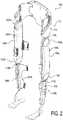
- a wearable robotic device 10can be worn by a user.
- the device 10can include attachment devices 11 for attachment of the device to the user via belts, loops, straps, or the like.
- the device 10can include padding 12 disposed along any surface likely to come into contact with the user.
- the device 10can be used with a stability aid 13, such as crutches, a walker, or the like.
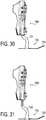
- FIGs. 2-6An exemplary wearable robotic device is illustrated as a powered lower limb orthosis 100 in FIGs. 2-6 .
- the orthosis 100 shown in FIGs. 2-6incorporates four motive devices (for example, electric motors), which impose sagittal plane torques at each hip joint 102R, 102L and knee joint 104R, 104L.
- FIG. 1shows the orthosis in a standing position while FIG. 3 shows the orthosis 100 in a seated position.
- the orthosiscontains five assemblies or modules, although one or more of these modules may be omitted and further modules may be added (for example, arm modules), which are: two lower leg assemblies (modules) 106R and 106L, two thigh assemblies 108R and 108L, and one hip assembly 110.
- Each thigh assembly 108R and 108Lincludes a thigh assembly housing 109R and 109L, respectively, and link, connector, or coupler 112R and 112L, respectively, extending from each of the knee joints 104R and 104L and configured for moving in accordance with the operation of the knee joints 104R and 104L to provide sagittal plane torque at the knee joints 104R and 104L.
- the connectors 112R and 112Lmay be further configured for releasably mechanically coupling each of thigh assembly 108R and 108L to respective ones of the lower leg assemblies 106R and 106L. Further, each thigh assembly 108R and 108L also includes a link, connector, or coupler 114R and 114L, respectively, extending from each of the hip joints 102R and 102L and moving in accordance with the operation of the hip joints 102R and 102L to provide sagittal plane torque at the knee joints 104R and 104L. The connectors 114R and 114L may be further configured for releasably mechanically coupling each of thigh assemblies 108R and 108L to the hip assembly 110.
- the various components of device 100can be dimensioned for the user.
- the componentscan be configured to accommodate a variety of users.
- one or more extension elementscan be disposed between the lower leg assemblies 106R and 106L and the thigh assemblies 108R and 108L to accommodate users with longer limbs.
- the lengths of the two lower leg assemblies 106R and 106L, two thigh assemblies 108R and 108L, and one hip assembly 110can be adjustable.
- thigh assembly housings 109R, 109L, the lower leg assembly housings 107R and 107L for the lower leg assemblies 106R, 106L, respectively, and the hip assembly housing 113 for the hip assembly 110can be configured to allow the user or prosthestist to adjust the length of these components in the field.
- these componentscan consist of slidable or movable sections that can be held in one or more positions using screws, clips, or any other types of fasteners.
- the two lower leg assemblies 106R and 106L, two thigh assemblies 108R and 108L, and one hip assembly 110can form a modular system allowing for one or more of the components of the orthosis 100 to be selectively replaced and for allowing an orthosis to be created for a user without requiring customized components.
- Such modularitycan also greatly facilitate the procedure for donning and doffing the device.
- each thigh assembly housing 109R, 109Lmay include substantially all the components for operating corresponding ones of the knee joints 104R, 104L and the hip joints 102R, 102L.
- each of thigh assembly housings 109R, 109Lmay include two motive devices (e.g., electric motors) which are used to drive the hip and knee articulations.
- the various embodimentsare not limited in this regard and some components can be located in the hip assembly 110 and/or the lower leg assemblies 106R, 106L.
- a battery 111 for providing power to the orthosiscan be located within hip assembly housing 113 and connectors 114R and 114L can also provide means for connecting the battery 111 to any components within either of thigh assemblies 108R and 108L.
- the connectors 114R and 114Lcan include wires, contacts, or any other types of electrical elements for electrically connecting battery 111 to electrically powered components in thigh assemblies 108R and 108L.
- the placement of battery 111is not limited to being within hip assembly housing 113. Rather, the battery can be one or more batteries located within any of the assemblies of orthosis 100.
- Wearable robotic devicesmay be especially difficult to don and doff because of the weight of the device, and/or due to physical limitations of users due to some medical condition.
- itmay be difficult to connect thigh assemblies to a hip assembly because one or more of these assemblies may be attached to the user's body already, and coupling may require both thigh assemblies to be coupled at the same time. Therefore, self-aligning and self-drawing couplers may ease donning and doffing of exemplary wearable robotic devices.
- An exemplary couplerincorporates a tapered joint connection with a tapered top portion that interfaces with a mating tapered receptacle to tightly secure the portions in place.
- Embodiments of this mechanical connectioncould also include an electrical interconnect 195 for power and/or other communication; these may include redundant contacts.
- FIG. 7shows a portion of the hip assembly 300 broken away in order to show the interior workings of the coupler.
- a thigh assembly 200 for attachment to a thigh of a userincludes a first portion 154 of the self-aligning, self-drawing coupler 150, and a hip assembly 300 for attachment to a hip region of the user has a second portion or receptacle 156 of the self-aligning, self-drawing coupler 150.
- a coupler between a thigh and a hip assemblysuch coupler may be used at any appropriate connection point of a wearable robotic device.
- the coupler 150may include a latch 152 configured to draw the first portion 154 of the self-aligning, self-drawing coupler to a latched position relative to the second portion 156 of the self-aligning, self-drawing coupler.
- the first portion 154 of the self-aligning, self-drawing couplerincludes a tapered male portion 158 receivable in a complimentary tapered female portion 160 of the second portion of the self-aligning, self-drawing coupler.
- These complimentary tapered portionscreate a self-aligning feature that assists a user when donning a wearable robotic device. For example, as long as the tapered positions are brought into general alignment, the shape of the pieces will cause the pieces to self-align when drawn together.
- the length of both the tapered male portion and tapered female portionis preferably longer than a widest width portion.
- the tapermay be in both a width and a depth direction along the length of the portions.
- Preferably the taperincludes a taper angle of between approximately 1 and 10 degrees.
- One embodimentmay include a friction reducing surface, such as Teflon®, on at least a portion of the interfacing surface between the male and female portions.
- an exemplary coupler 150may include a four bar linkage including an input link 162, a floating link 168, an output link 170, and a ground link 172 to aid in connecting the two separate components of a wearable robotic device. It may include a manually operable (i.e. operable without tools) lever 163 as the input link 162 with a cantilever portion 164 connecting to the floating link 168.
- a sliding latch element 152is attached at a first end 174.
- the latch element 152may be resilient.
- the other end 176 of the sliding latch elementmay be restricted to sliding in a guideway or channel 178 for controlling motion of the latch element during operation.
- the guideway 178may include a generally straight draw portion 180 aligned with the female portion of the coupler, and an engagement portion 182 extending laterally away from the draw portion for guiding the latch element into and out of engagement with a corresponding latch element 190 of the second portion 154 of the coupler.
- the guideway the sliding latch element is contained to be withinallows the sliding latch element to move in either direction based on the position and direction of the input lever. This movement allows the latch mechanism to draw the connecting link into the receptacle or to eject the link from the receptacle, as shown in FIGs. 12 and 13 , respectively.
- the sliding latch elementrides in a channel that is curved to push the sliding latch element out of the way in the fully open position allowing for unobstructed removal or insertion.
- the resilient latch element 152may provide a biasing force in the linkage mechanism for locking the linkage mechanism in an over-center configuration.
- the over-center positionmay be either in a locked open position as illustrated in FIG. 9 , or a locked close position as illustrated in FIG. 11 , although, preferably, it is both.
- the resilient latchwhen in an over-center, locked close position, holds the input lever closed with the spring load and takes up tolerance in the hip link.
- the resilient latchwhen in an over-center, locked close position, can secure the lever in an open position and secure the sliding latch element in a position that prevents the sliding latch element from blocking the connecting link during insertion.
- the connecting linkWhen the connecting link is inserted, it will catch the sliding latch element 152. With the connecting link partially inserted, the input lever of the four bar linkage can be used to fully insert the connecting link, creating a self-drawing feature.
- the male portion of the couplermay include a notch 190 that the sliding latch element can interface with and pull or push the connecting link. This controlled action provides a consistent connection of the link.
- the sliding latch element and notchcan be used to "key" the connecting link to prevent improper insertion. This also prevents incorrect electrical connections.
- the connectors 112R, 112L, 114R, and 114L, and/or the self-aligning, self-drawing coupler 150can be configured to provide mechanical and electrical connections.
- wirescan be routed through the interior of connector 112R to electrical contacts.
- a corresponding set of electrical contacts 190would also be provided in the interior of the female portion. Accordingly, when a male portion is locked into the female portion, the electrical contacts are placed in contact with the corresponding electrical contacts within the female portion.
- a similar configurationcan be provided for links 112L, 114R, and 114L. It is noted though that the various embodiments self-aligning, self-drawing coupler may be used on any suitable device and may, in particular, be used with any other exemplary devices disclosed herein.
- a substantially planar drive systemis used to drive the hip and knee articulations.
- each motorcan resepectively drive an associated joint through a speed-reduction transmission using an arrangement of sprocket gears and chains substantially parallel to the plane of sagittal motion.
- the powered jointsmay be implemented by disposing a joint sprocket gear 504 at one end of thigh assembly housing 109R parallel to the sagittal plane and configuring the joint sprocket gear 504 to rotate parallel to the sagittal plane.
- the connector 112Rcan extend from the joint sprocket gear 504 and be mechanically connected, so that rotation of the joint sprocket gear 504 results in application of torque to the lower leg assembly 106.
- a slot or receiving elementcan be provided for the connector 112R to link the thigh assembly 108R and lower leg assembly 106R.
- the receiving element and the connector 112Rcan be configured such that the connector can removably connect the thigh assembly 108R and lower leg assembly 106R.
- clips, screws, or any other types of fastener arrangementscan be used to provide a permanent or a removable connection.
- quick connect or "snap-in" devicescan be provided for providing the connection. That is, these quick connect devices allow connections to be made without the need of tools. These types of quick connect devices can not only be used for mechanically coupling, but for electrical coupling. In some embodiments, a single quick connect device can be used to provide both electrical and mechanical coupling. However, the various embodiments are not limited in this regard and separate quick connect devices can be provided for the electrical and mechanical coupling.
- the orthosiscan be easily separated into three or five modular components - right thigh, left thigh, right lower leg, left lower leg, and hip assemblies - for ease of donning and doffing and also for increased portability.
- the knee joint 104Rmay be actuated via operation of a motor 502, as discussed above.
- the motor 502can be an electric motor that drives the knee joint 104R (i.e., joint sprocket gear 504) using a two-stage chain drive transmission.
- a first stagecan consist of the motor 502 driving, either directly or via a first chain, a first drive sprocket gear 514.
- the first drive sprocket gear 514is mechanically coupled to a second drive sprocket gear 516 so that they rotate together about the same axis based on the power applied by motor 502 to first drive sprocket gear 514.
- the second drive sprocket gear 516can be arranged so that it is disposed in the same plane as the joint gear 504. Thus, a second chain can then be used to drive joint sprocket gear 504 using the second drive sprocket gear 516 and actuate the knee joint 104R.
- the gear ratios for the various components described abovecan be selected based on a needed amount of torque for a joint, power constraints, and space constraints.
- Each stage of the chain drive transmissioncan include tensioners, which can remove slack from a chain and mitigate shock loading.
- tensionerscan be adjustable or spring loaded.
- a brake 570can be provided for motor 502.
- a solenoid brakemay be provided which engages a brake pad against the rotor 524 of the motor 502 in one state, and disengages the brake pad in another state.
- the various embodimentsare not limited to this particular brake arrangement and any other methods for providing a brake for motor 502 can be used without limitation.
- FIG. 20has been discussed above with respect to an arrangement of sprocket gears and chains.
- the various embodimentsare not limited in this regard. That is, any other arrangement of gears, with or without chains, and providing a reduced profile can be used.
- the various embodiments disclosed hereinare not limited to an arrangement of gears and/or chains.
- a belt and pulley arrangementcould be used in place of the chain and sprocket arrangement.
- a friction drive arrangementcan also be used.
- any combination of the arrangements discussed abovecan be used as well. Additionally, different joints can employ different arrangements.
- a motor for each of joints 102R, 102L, 104R, 104Lcan be configured to provide a baseline amount of continuous torque and a higher amount of torque for shorter periods of time. For example, in one configuration, at least 10 Nm of continuous torque and at least 25 Nm of torque for shorter (i.e., 2-sec) durations are provided. In another example, up to 12 Nm of continuous torque and 40 Nm of torque for shorter (i.e., 2-sec) durations.
- both knee joints 104R and 104Lcan include normally locked brakes, as discussed above, in order to preclude knee buckling in the event of a power failure.
- cassettesallow for ease of maintenance and replacement because cassettes are swappable, making them easier to service or requiring less of a variety in spare components.
- self-containedmeans that the cassette includes everything necessary to operate in a fully functional manner if supplied with power. Thus, for example, if power is supplied to electrical contacts of the cassette, the cassette would actuate.
- the motoris integrated onto a common baseplate along with sprockets that control the motion of a joint link.
- Bearings and chains, with and/or without tensionersprovide smooth and efficient transfer of motion from the motor to the joint angle. Integrating the motor into the cassette allows for a thinner overall package configuration and provides consistent alignment among parts. Moreover, integrating the motor also creates a larger surface area to transfer and emit heat generated by the motor.
- these cassettesmay pertain to a specific joint or set of joints on the device.
- Eachmay have a unique actuation unit or share an actuation unit. They may include actuators, with or without a power source, and/or a method of transmitting movement.
- the illustrated embodimentincludes a brushless DC motor with chains and sprockets to create and transmit motion, however other embodiments may utilize electric motors, linear actuators, piezoelectric actuators, belts, ball screws, harmonic drive, gear drive (bevel or planetary), or any combination thereof.
- One embodimentmay also house electronics and/or sensors.
- the self-contained unit(s)can be preassembled to aid in manufacturing the broader device. This allows for quick servicing of the device since individual cassettes can be swapped out and serviced.
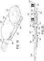
- a removable, self-contained, ovular actuator cassette 500may be receivable in a receptacle of a wearable robotic device.
- the cassette 500may include a first circular portion 520 housing a motive device (e.g., an electric motor) 502.
- a second circular portion 522may be longitudinally offset and longitudinally overlapping the first circular portion and may house a first portion of a drivetrain 514, 516 operatively coupled to and driven by the motive device 502.
- a third circular portion 524may be longitudinally offset from the first and second circular portions and longitudinally overlapping the second circular portion and may house a second portion of the drivetrain 504.
- an ovular housing 530may support the motive device 502 and drivetrain 502, 514, 516. Long sides of the ovular housing are straight and parallel with each other and tangentially terminate as curved end surfaces of the ovular housing.
- An output 112Rmay protrude from and be rotatable with respect to the housing and driven by the drivetrain.
- the housingmay include a top plate 532 on which the motive device is mounted. As shown in FIG. 20 , the drive shaft of the motive device 502 may protrude through the top plate 532.
- the housingmay also include a bottom plate 534 coupled to the top plate 532.
- the drive trainis sandwiched between and supported by the top plate 532 and the bottom plate 534.
- the motive device 502is mounted outside the top and bottom plates on a laterally offset portion 536 of the top plate.
- the maximum depth of the cassette measured along a rotational axis of the motive deviceis less than the maximum width and the maximum length of the cassette, thereby achieving a thin, flat profile.
- the output 112Rmay protrude through an output opening 540.
- Slide covers 542 disposed in the output opening and movable with the output 112R to cover portions of the output opening not occupied by the outputmay also be provided.
- brushed covers or other means known in the artmay be used to protect the interior of the cassette from contamination.
- the output 112Rmay be the first portion of the self-aligning, self-drawing coupler discussed above.
- the cassettemay be disposed in an appropriate receptacle 560 of the thigh assembly.
- a wearable robotic deviceoften needs to be donned and doffed under difficult circumstances, including, for example, by a user who is paralyzed. Therefore, an improved attachment system is desirable.
- a body assemblymay include an attachment device 600, 600' for attaching to the first portion of the user's body.
- the attachment devicemay include a tensioning system 650, 650' for retention of the first body assembly to the user's body.
- the tensioning systemincludes both a tensionable member 652, 652' and a tensioning member 654, 654'.
- a cable or lace 656, 656'is threaded through a looped strap 658, 658' and connected back onto itself.
- the tensioning systempreferably includes a cable reel system having a cable reel 660, 660' and a cable 656, 656' extending from the reel, and cable guides (not shown).
- the reelmay be a spring-loaded rotating spool that winds or unwinds the cable to either tension or untension the cable.
- Suitable devices to use for the reelare cable reel devices available under the name BOA from Boa Technology, Inc. of Denver, Colo., and described in U.S. Pat. Nos. 7,954,204 and 7,992,261 .
- the reelmay be mounted to the substrate 670, 670', as by use of plastic rivets, and the like.
- the cable reelis a rotating spool that winds or unwinds the cable and, preferably includes a toothed housing configured for receiving the ends of the cable, each end rotationally linked to a spool contained within the housing of the cable reel.
- a knob having a spring-loaded assemblycooperates with the housing and the spool for manually winding the cable around the spool.
- the knob and spring-loaded assemblycooperate to engage the spool with the housing to provide a ratchet feature for winding the spool when the knob is turned in one direction to tension the cable, and for releasing the spool to untension the cable.
- the cablemay be, for example, a nylon coated, stainless steel cable.
- the cable reel 660, 660'may be mounted to a plastic support piece (not shown) that retains the housing with or without the need for other retention methods, such as thread, removable brackets, adhesives, etc.
- the strapdoes not extend beyond the plastic support base.
- the inventionutilizes the support base as a low friction surface for the strap to slide against and provides a larger surface area for the lace to distribute pressure.
- the spoolretracts the lace the strap is effectively shortened as it is pulled toward the spool at the base of the support. This shortening tightens the strap when it is attached at one end and the support is attached at another, completing a loop.
- the tail of the strap 658'is attached to a rigid structure of the body assembly at attachment anchor 664, 664'.
- the attachmentis temporary, allowing for the entire strap to be adjusted or removed.
- Some methods for attachmentcould include threading it back on itself, hook and loop fasteners, button fasteners, or any combination of the above or other fastening method.
- Exemplary embodimentsthread the strap 658' through a series of slots to create adequate friction that secures the strap. This method allows the strap to be adjusted to accommodate a wide range of overall lengths.
- the strapmay be composed of or contain hook or loop material that can be used to secure the strap to the frame at an attachment anchor 664' or to attach other accessories, such as padding.
- the attachment devicemay include a sleeve to contain the support, lace, and strap.
- Paddingmay be placed on the back side of the support 670. This could be adhered to the support, to the sleeve (if present) or floating in place. The padding aids further in the comfort and distribution of pressure.
- a mechanism for attaching the support to the framemay include a quick connect/disconnect.
- a preferred embodimentincludes a button hole and post design, as detailed in FIGs. 23-27 .
- the keyholeincludes a first circular opening overlapping a second, larger circular opening, the larger circular opening disposed distal the first, smaller opening in relation to the button 680.
- the keyhole structureallows for the buckle to slide over the larger diameter of the button head and slide tight around the post.
- One embodimentmay include both the button/post and keyhole features to be secured to straps; when they are connected they join the two.
- the present inventiondiscloses a round post that allows the buckle to revolve. Further, the bottom portion of the button head 684, just above the connection to the post is slightly curved. This curvature allows the clip 690 to pivot. The degree of pivot is dependent on the height of the post in relation to the thickness of the buckle and the curvature of the bottom of the button relative to the diameter of the post.
- the button hole and post connect/disconnect methodcan be use independently of the tensioning strap method to secure other strapping to a frame or another strap.
- This buckle and clip designcan be used independently or combined with other strapping methods.
- the adjustable and removable strapsallow for coarse adjustment of the attachment device, while tensioning by the cable reel allows for fine adjustment of the attachment device.
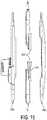
- the lower-leg assembly 106L, 106Rmay include an ankle foot orthotic (AFO) 700 that can be used independently or attach to a joint, such as one found on a wearable robotic device.
- AFOankle foot orthotic
- Preferred embodimentsinclude a quick connect/disconnect 702 between the lower-leg assembly and the rest of the robotic system so that, for example, the lower leg assembly could be worn all day, and the rest of the wearable robotic assembly could be attached when required. This can result in much quicker and easier donning and doffing, as a dedicated AFO would not have to be removed from under a shoe and replaced by an AFO integrated into a wearable robotic device.
- exemplary lower-leg assembliesallow for the length to be adjusted while worn by the user or separate from the user.
- One embodimentmay include markings to indicate total assembly length or that can be used to determine said length.
- the lower leg assembly 106Lincludes an AFO having a plantar element 720 which may be of a rigid, thin-sheeted material. This plantar element would be placed under the sole of a user's foot, and may fit within a shoe.
- a leg element 722may also be made of rigid thin-sheeted material, and may have a lower portion 724 rigidly connected to and extending upwardly from the plantar element. The lower portion of the leg element and the plantar element are adjustably coupled to the housing 726 of the lower-leg assembly.
- the lateral side of the illustrated AFOprovides load bearing support, other embodiments may bear support at the front, rear, medial, or any combination thereof.
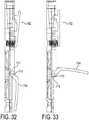
- exemplary embodimentsmay include a quick adjust mechanism 710, shown in more detail in FIGs. 32 and 33 , utilizing a cam lock 712 device movable by way of a manually operated lever 714 that allows for infinitely variable length between a maximum and a minimum without the use of tools or power source.
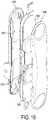
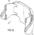
- a hip assembly 800includes pivoting hip wings as part of an attachment device that attaches a portion of a wearable robotic device to a user. Because these wings may be standard sizes or semi-customized or customized to the user customized to a user based on size and/or support needed based on physical limitations of the user, the wings may need to be removed on a regular basis in clinical settings. Therefore, exemplary embodiments include a quick connect/disconnect mechanism that is manually operable (i.e. operable without tools).
- An exemplary wearable robotic deviceincludes a hip assembly 800 attachable to a hip region of a user's body and coupled to another body assembly (e.g., a thigh assembly) and rotatable with respect to the first body assembly via a motive device housed in at least one of the first body assembly or the hip assembly.
- the hip assemblyincludes a rigid housing 810 and a removable attachment device or hip wing 820 attachable to the hip region of a user's body and removable from the rigid housing by operation of a manually operable removal mechanism 830.
- FIG. 35shows a detailed view of the hip assembly with the hip wing 820 removed and the removal mechanism 830 visible.
- FIG. 36shows another detailed view of the hip assembly, this time with a portion of the rigid housing 810 removed for clarity.
- the removal mechanismmay be a quick-release hinge pin.
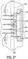
- the removal mechanism 830includes a central guide cylinder 832 housing a spring 834 longitudinally outwardly biasing first and second finger-operated pins 836, 838 slidably disposed on opposite longitudinal sides of the guide cylinder.
- These pins or end capsact as hinges when installed with the wings on the rigid housing. When the end caps are pinched together, compressing the spring, the pins retract into the ridged frame, allowing the wings to be freely removed or inserted.
- the guide cylinderprevents the spring from buckling during compression and may reduce friction to minimize force to activate the latch to release the wings.
- the wing releaseis not exposed during operation. Rather, laterally extending grip portions 840, 842 may protrude into a battery receptacle 870. This way, the wings cannot be removed when the battery 860 is in place because access to the removal mechanism is precluded when the battery is installed in the battery receptacle. Further, the battery may be shaped such that the battery cannot be connected if wings are only partially installed.
- the battery receptaclefurther includes electrical contacts 890 for mating with corresponding electrical contacts of the battery (not shown).
- the hip assembly 900is substantially the same as the above-referenced hip assembly 800, and consequently the same reference numerals but indexed by 100 are used to denote structures corresponding to similar structures in the hip assembly.
- the foregoing description of the hip assembly 800is equally applicable to the hip assembly 900 except as noted below.
- aspects of the hip assembliesmay be substituted for one another or used in conjunction with one another where applicable.
- the hip assemblyincludes a rigid housing 910 and a removable attachment device or hip wing 920 attachable to the hip region of a user's body and removable from the rigid housing by operation of a manually operable removal mechanism 930.
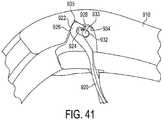
- FIG. 41shows a detailed sectioned view of the hip assembly with the hip wing 920 detached from the rigid housing 910 and the removal mechanism 930 visible.
- the removal mechanismis a combination of features that will be described further below. It is noted that more than one removal mechanism 930 may be included on each hip wing 920.
- the depicted hip wingincludes upper and lower attachment portions 921, 923, and each of these attachment portions may include one or more attachment points 925, 927.
- the hip wing/removable attachment device 920includes a hooked hinge portion 922 with an inner hook surface 924 and an outer hook surface 926.
- the outer hook surfacepartially circumscribes a rotational axis 933 of the hip wing when the hip wing is attached to the rigid housing.
- the inner hook surface 924engages with the hinge pin 932 and the removable attachment device rotates around the hinge pin when attached to the rigid housing.
- the hinge pin 932extends axially through the rigid housing 910 and acts as a hinge pin for every attachment point of the hip wing 920.
- the inner and or outer hook surfaces 924, 926are circular. If the hinge pin is also circular, the inner hook surface 924 may contact the hinge pin along the entire extent of the inner hook surface, or at least the portion thereof that is also circular.
- the hook portion 922has an opening 928 into which the hinge pin 932 passes when attaching and detaching the hip wing 920.
- This opening 928is optionally the same width as the diameter of the hinge pin 932, therefore allowing unimpeded attachment and detachment.
- the opening 928may be larger and may taper inwardly in order to more easily guide and attach the hooked portion 922 onto the pin 932.
- the openingmay include a portion that is narrower than the hinge pin so as to produce a positive detent snap-connection between the hinge pin 932 and the hook portion 922 via spring-like deformation of the hook portion 922.
- the rigid housing 910includes a radially inward facing hinge guide surface 934 radially offset from and partially circumscribing the hinge pin 932.
- the outer hook surface 924may engage the hinge guide surface 934 such that the hooked hinge portion 922 is sandwiched between the hinge pin 932 and the hinge guide surface 934 when the hip wing is attached to the rigid housing.
- the rigid housingincludes a detachment pocket 935 into which the hooked hinge portion 922 may be slid to disengage the hooked hinge portion from the hinge pin 932 to detach the hip wing from the rigid housing 910.
- the hooked hinge portion 922is in the detachment pocket 935.
- the detachment pocketincludes a flat wall 936 that acts with a flat portion 929 of the outer hook surface 926 to provide a positive stop for a user when attaching the hip wing to the rigid housing.
- the detachment pocket 935is adjacent the guide surface 934 and is deep enough for the hooked hinge portion 922 to clear the hinge pin 932 so as to allow complete removal of the hip wing 920 from the rigid housing 910.
- FIG. 42shows the hip wing being slid onto the hinge pin 932 from the position shown in FIG. 41 .
- FIG. 43shows the hip wing being rotated out to a "normal" or “operative” position to engage the hooked hinge portion 922 with the guide surface 934 from the position shown in FIG. 42 .
- Removal of the hip wing 920 from the rigid housing 930may be accomplished by the opposite order of movements shown in FIGs. 41-43 .
- a method for removing the hip wingincludes rotating the hip wing about the hinge pin until the hooked hinge portion 922 is aligned with the pocket 935. This rotational movement is preferably a rotation of the hip wing inward toward the middle of the rigid housing. This movement disengages the hooked hinge portion 922 from the guide surface 934. Once aligned, the hooked hinge portion 922 is slid into the pocket 935 to disengage from the hinge pin 932.
- the hip wing 920may be removed from the rigid housing.
- the foregoing manual removal methodhas the advantage of preventing accidental or purposeful removal of the hip wing during use of the wearable robotic device.
- the body of the userwould prevent rotation of the hip wing inwardly toward the middle of the rigid housing, therefore, the hooked hinge portion would be prevented from disengaging with the guide surface and the hinge pin.
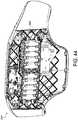
- exemplary embodimentsmay optionally include an integral or permanently-installed battery, in contrast to the removable battery described above.
- FIG. 44shows such a permanently installed battery 960 in the rigid housing of the hip assembly.
- Fig. 45shows an exemplary hip assembly from the back side, and it is evident that the permanently-installed battery allows for the benefit of fewer parts in this assembly (such, as for example, no need for separate battery contacts, a battery lock mechanism, or a battery latch mechanism.
- the back of the hip assemblyis now able to be free of seems, allowing for a cleaner, sleeker look, more surface are for branding, a more easily-cleanable product, and fewer surface discontinuities that could catch on clothing or other environmental objects.
- the battery 960may be charged via a battery port 965 which may be located anywhere that is convenient, but is preferably mounted to an underside of the hip assembly as shown in FIG. 46 .
- An underside mountmay have the advantage of preventing debris from the environment (such as, for example, dust and rain) from entering or blocking the battery port 965.
Landscapes
- Health & Medical Sciences (AREA)
- Engineering & Computer Science (AREA)
- Life Sciences & Earth Sciences (AREA)
- Animal Behavior & Ethology (AREA)
- General Health & Medical Sciences (AREA)
- Public Health (AREA)
- Veterinary Medicine (AREA)
- Physical Education & Sports Medicine (AREA)
- Rehabilitation Therapy (AREA)
- Pain & Pain Management (AREA)
- Epidemiology (AREA)
- Robotics (AREA)
- Mechanical Engineering (AREA)
- Nursing (AREA)
- Orthopedic Medicine & Surgery (AREA)
- Biomedical Technology (AREA)
- Heart & Thoracic Surgery (AREA)
- Vascular Medicine (AREA)
- Rehabilitation Tools (AREA)
- Manipulator (AREA)
- Prostheses (AREA)
Description
- The present invention relates generally to wearable robotic devices, and more particularly to improvements in operability to powered lower limb orthoses.
- There are currently about 262,000 spinal cord injured (SCI) individuals in the United States, with roughly 12,000 new injuries sustained each year at an average age of injury of 40.2 years. Of these, approximately 44% (5300 cases per year) result in paraplegia. One of the most significant impairments resulting from paraplegia is the loss of mobility, particularly given the relatively young age at which such injuries occur. Surveys of users with paraplegia indicate that mobility concerns are among the most prevalent, and that chief among mobility desires is the ability to walk and stand. In addition to impaired mobility, the inability to stand and walk entails severe physiological effects, including muscular atrophy, loss of bone mineral content, frequent skin breakdown problems, increased incidence of urinary tract infection, muscle spasticity, impaired lymphatic and vascular circulation, impaired digestive operation, and reduced respiratory and cardiovascular capacities.
- In an effort to restore some degree of legged mobility to individuals with paraplegia, several lower limb orthoses have been developed. The simplest form of passive orthotics are long-leg braces that incorporate a pair of ankle-foot orthoses (AFOs) to provide support at the ankles, which are coupled with leg braces that lock the knee joints in full extension. The hips are typically stabilized by the tension in the ligaments and musculature on the anterior aspect of the pelvis. Since almost all energy for movement is provided by the upper body, these (passive) orthoses require considerable upper body strength and a high level of physical exertion, and provide very slow walking speeds. The hip guidance orthosis (HGO), which is a variation on long-leg braces, incorporates hip joints that rigidly resist hip adduction and abduction, and rigid shoe plates that provide increased center of gravity elevation at toe-off, thus enabling a greater degree of forward progression per stride. Another variation on the long-leg orthosis, the reciprocating gait orthosis (RGO), incorporates a kinematic constraint that links hip flexion of one leg with hip extension of the other, typically by means of a push-pull cable assembly. As with other passive orthoses, the user leans forward against the stability aid while un weighting the swing leg and utilizing gravity to provide hip extension of the stance leg. Since motion of the hip joints is reciprocally coupled through the reciprocating mechanism, the gravity-induced hip extension also provides contralateral hip flexion (of the swing leg), such that the stride length of gait is increased. One variation on the RGO incorporates a hydraulic-circuit-based variable coupling between the left and right hip joints. Experiments with this variation indicate improved hip kinematics with the modulated hydraulic coupling.
- In order to decrease the high level of exertion associated with passive orthoses, the use of powered orthoses has been previously investigated, which incorporate actuators and an associated power supply to assist with locomotion. These orthoses have been shown to increase gait speed and decrease compensatory motions, relative to walking without powered assistance, however, the development of these orthoses is still in its infancy.
- A known wearable robotic device is described in
JP2011156344 KR20130045874 EP1637116 ,US2010/298746 andUS2014/005798 . - The present invention provides a wearable robotic device as defined in the appended claims.
- The wearable robotic device includes a first body assembly for attachment to a first portion of a user's body; a second body assembly for attachment to a second portion of the user's body; an actuator having first and second actuator portions respectively connected to the first and second body assemblies and configured to move the first and second body assembly relative each other; an attachment device for attaching to the first portion of the user's body, the attachment device including a tensioning system for retention of the first body assembly to the first portion of the user's body, including a coarse adjuster and a separate fine adjuster. The coarse adjuster comprises a strap that is attached to the fine adjuster such that the fine adjuster is operable to shorten a strap length, the fine adjuster being mounted to a support piece that provides a low friction surface for sliding of the strap, and the strap has an end that is removably attachable to a rigid structure of the first or second body assembly to uncouple the tensioning system from the first or second body assembly.
- Optionally, the fine adjuster includes a tensioning member and a tensionable member.
- Optionally, the tensioning member includes a ratchet.
- Optionally, the tensioning member includes a cable reel and the tensionable member includes a cable acted upon by the cable reel to tension the cable.
- Optionally, the strap is releasably coupled at a second end to a second strap anchor of the one body assembly.
- Optionally, the attachment point of the strap to the strap anchor is adjustable.
- Optionally, the strap is an adjustable length strap.
- Optionally, the attachment device is removably coupled to the first body assembly at one end of the attachment device by a buckle.
- Optionally, the buckle is rotatable with respect to the first body assembly in two orthogonal directions.
- The foregoing and other features of the invention are hereinafter described in greater detail with reference to the accompanying drawings.
FIG. 1 shows a wearable robotic device being worn by a user;FIG. 2 shows a perspective view of an exemplary wearable robotic device in a standing position;FIG. 3 shows a perspective view of the exemplary wearable robotic device in a seated position;FIG. 4 shows a front view of the exemplary wearable robotic device in a standing position;FIG. 5 shows a left view of the exemplary wearable robotic device in a standing position;FIG. 6 shows a back view of the exemplary wearable robotic device in a standing position;FIG. 7 shows a broken detail view of a portion of an exemplary wearable robotic device having a self-aligning, self-drawing coupler at the hip joint;FIG. 8 shows a simplified view of the linkage mechanism of the self-aligning, self-drawing coupler;FIG. 9 shows a broken detail view of a portion of the exemplary wearable robotic device having a self-aligning, self-drawing coupler at the hip joint with the coupler latch mechanism in a locked open position;FIG. 10 shows a broken detail view of a portion of the exemplary wearable robotic device having a self-aligning, self-drawing coupler at the hip joint with the coupler latch mechanism in a closing position;FIG. 11 shows a broken detail view of a portion of the exemplary wearable robotic device having a self-aligning, self-drawing coupler at the hip joint with the coupler latch mechanism in a locked close position;FIG. 12 shows a detail view of the self-aligning, self-drawing coupler at the hip joint with the coupler latch mechanism in a closing position;FIG. 13 shows a detail view of the self-aligning, self-drawing coupler at the hip joint with the coupler latch mechanism in an opening position;FIG. 14 shows a perspective view of an exemplary thigh assembly having two exemplary actuator cassettes installed therein;FIG. 15 shows a front exploded view of the exemplary thigh assembly having two exemplary actuator cassettes installed therein;FIG. 16 shows a perspective exploded view of the exemplary thigh assembly having two exemplary actuator cassettes installed therein;FIG. 17 shows a top view of an exemplary actuator cassette;FIG. 18 shows a bottom view of an exemplary actuator cassette;FIG. 19 shows a perspective view of an exemplary actuator cassette;FIG. 20 shows a cross-sectional view of an exemplary actuator cassette taken along the longitudinal direction;FIG. 21 shows an exemplary attachment device for use in an exemplary hip assembly having a retention system with a tensionable member and a tensioning member;FIG. 22 shows an exemplary attachment device according to the claimed invention for use in an exemplary lower leg assembly having a retention system with a tensionable member and a tensioning member;FIG. 23 shows a perspective view of an exemplary buckle for use in an exemplary attachment device;FIG. 24 shows a side view of the exemplary buckle for use in an exemplary attachment device according to the claimed invention;FIG. 25 shows an exemplary button and post for use in an exemplary clip of an exemplary attachment device;FIG. 26 shows an exemplary clip without an attached button;FIG. 27 shows another view of the exemplary clip without an attached button;FIG. 28 shows an exemplary attachment device according to the claimed invention for use in an exemplary hip assembly having a retention system with a tensionable member and a tensioning member;FIG. 29 shows an exemplary lower leg assembly having an exemplary integrated ankle-foot orthotic;FIG. 30 shows another view or the exemplary lower leg assembly having an exemplary integrated adjustable ankle-foot orthotic with the orthotic retracted;FIG. 31 shows another view of the exemplary lower leg assembly having an exemplary integrated adjustable ankle-foot orthotic with the orthotic partially extended;FIG. 32 shows a portion of an exemplary lower-leg assembly having a quick connect coupler at the top end and a cam-lock adjuster at a lower end in a locked position for use with an exemplary ankle-foot orthotic;FIG. 33 shows a portion of an exemplary lower-leg assembly having a quick connect coupler at the top end and a cam-lock adjuster at a lower end in an unlocked position for use with an exemplary ankle-foot orthotic;FIG. 34 shows an exemplary hip assembly with a removable hip wing;FIG. 35 shows a partial view of the hip assembly with the hip wing removed;FIG. 36 shows a partial view of the hip assembly with a portion of the housing removed to show the interior of the hip assembly;FIG. 37 shows a partial view of the hip assembly with a portion of the housing removed and the guide cylinder invisible to show the spring of the removal mechanism;FIG. 38 shows a rear view of the exemplary hip assembly with the battery installed in the batter receptacle;FIG. 39 shows a rear view of the exemplary hip assembly with the battery not installed in the batter receptacle, revealing the removal mechanism of one of the hip wings;FIG. 40 shows a partial view of the hip assembly with another exemplary attachment mechanism between the hip wing and the rigid housing of the hip assembly;FIG. 41 shows a sectioned view of the hip assembly with the hip wing disconnected from the hinge pin of the rigid housing;FIG. 42 shows another sectioned view of the hip assembly with the hip wing engaged with the hinge pin;FIG. 43 shows another sectioned view of the hip assembly with the hip wing engaged with the hinge pin and with a guide surface of the rigid housing;FIG. 44 shows a permanently installed battery with the back cover removed from the hip assembly;FIG. 45 shows an exemplary hip assembly with a permanently installed battery; andFIG. 46 shows an exemplary hip assembly with a battery charging port located under the hip assembly.- Although the various embodiments will be discussed at times with respect to orthoses for providing mobility assistance for users with paraplegia, the various embodiments are not limited in this regard. The various embodiments are equally application to other applications. For example, these can include mobility assistance for users with other conditions other than paraplegia, rehabilitation and mobility assistance for stroke-impaired users, and mobility assistance for users with neuromuscular disabilities that impair legged mobility, to name a few, including human and non-human users. Further, embodiments may be applied to other wearable robotic devices such as strength-enhancing exoskeletons for use in military, construction, or other applications. Thus, the various embodiments can be applied to any applications in which mobility assistance or enhancement is needed, either permanently or temporarily.
- Further, although the various embodiments will be generally described with respect to the exemplary orthosis described below, the various embodiments are not limited to this particular configuration. The various embodiments can be embodied in or used with any type of exoskeleton system, such as the orthosis described below and further illustrated in design application number
29/486,534 WO 2012/044621 . - The terms "exoskeleton system," "exoskeleton," and "wearable robotic device," as used herein, refer to any type of device that can be worn or otherwise attached to a user, where the device is configured to provide energy for motion and or support of the one or more portions of the user.
- As show in
FIG. 1 , a wearablerobotic device 10 can be worn by a user. To attach the device to the user, thedevice 10 can includeattachment devices 11 for attachment of the device to the user via belts, loops, straps, or the like. Further, for comfort of the user, thedevice 10 can includepadding 12 disposed along any surface likely to come into contact with the user. Thedevice 10 can be used with astability aid 13, such as crutches, a walker, or the like. - An exemplary wearable robotic device is illustrated as a powered
lower limb orthosis 100 inFIGs. 2-6 . Specifically, theorthosis 100 shown inFIGs. 2-6 incorporates four motive devices (for example, electric motors), which impose sagittal plane torques at each hip joint 102R, 102L and knee joint 104R, 104L.FIG. 1 shows the orthosis in a standing position whileFIG. 3 shows theorthosis 100 in a seated position. - As seen in the figures, the orthosis contains five assemblies or modules, although one or more of these modules may be omitted and further modules may be added (for example, arm modules), which are: two lower leg assemblies (modules) 106R and 106L, two
thigh assemblies hip assembly 110. Eachthigh assembly thigh assembly housing coupler - The
connectors thigh assembly lower leg assemblies thigh assembly coupler hip joints hip joints connectors thigh assemblies hip assembly 110. - In some embodiments, the various components of
device 100 can be dimensioned for the user. However, in other embodiments, the components can be configured to accommodate a variety of users. For example, in some embodiments, one or more extension elements can be disposed between thelower leg assemblies thigh assemblies lower leg assemblies thigh assemblies hip assembly 110 can be adjustable. That is,thigh assembly housings leg assembly housings lower leg assemblies hip assembly housing 113 for thehip assembly 110 can be configured to allow the user or prosthestist to adjust the length of these components in the field. For example, these components can consist of slidable or movable sections that can be held in one or more positions using screws, clips, or any other types of fasteners. In view of the foregoing, the twolower leg assemblies thigh assemblies hip assembly 110 can form a modular system allowing for one or more of the components of theorthosis 100 to be selectively replaced and for allowing an orthosis to be created for a user without requiring customized components. Such modularity can also greatly facilitate the procedure for donning and doffing the device. - In
orthosis 100, eachthigh assembly housing hip joints thigh assembly housings hip assembly 110 and/or thelower leg assemblies - For example, a
battery 111 for providing power to the orthosis can be located withinhip assembly housing 113 andconnectors battery 111 to any components within either ofthigh assemblies connectors battery 111 to electrically powered components inthigh assemblies battery 111 is not limited to being withinhip assembly housing 113. Rather, the battery can be one or more batteries located within any of the assemblies oforthosis 100. - Wearable robotic devices may be especially difficult to don and doff because of the weight of the device, and/or due to physical limitations of users due to some medical condition. In particular, it may be difficult to connect thigh assemblies to a hip assembly because one or more of these assemblies may be attached to the user's body already, and coupling may require both thigh assemblies to be coupled at the same time. Therefore, self-aligning and self-drawing couplers may ease donning and doffing of exemplary wearable robotic devices.
- An exemplary coupler incorporates a tapered joint connection with a tapered top portion that interfaces with a mating tapered receptacle to tightly secure the portions in place. Embodiments of this mechanical connection could also include an
electrical interconnect 195 for power and/or other communication; these may include redundant contacts. - Refering specifically to
Figures 7-13 , shown is an exemplary self-aligning, self-drawing coupler for use in a wearable robotic device. In particular,Fig. 7 shows a portion of thehip assembly 300 broken away in order to show the interior workings of the coupler. - A
thigh assembly 200 for attachment to a thigh of a user includes afirst portion 154 of the self-aligning, self-drawingcoupler 150, and ahip assembly 300 for attachment to a hip region of the user has a second portion orreceptacle 156 of the self-aligning, self-drawingcoupler 150. Although illustrated as a coupler between a thigh and a hip assembly, such coupler may be used at any appropriate connection point of a wearable robotic device. - The
coupler 150 may include alatch 152 configured to draw thefirst portion 154 of the self-aligning, self-drawing coupler to a latched position relative to thesecond portion 156 of the self-aligning, self-drawing coupler. - The
first portion 154 of the self-aligning, self-drawing coupler includes a taperedmale portion 158 receivable in a complimentary taperedfemale portion 160 of the second portion of the self-aligning, self-drawing coupler. These complimentary tapered portions create a self-aligning feature that assists a user when donning a wearable robotic device. For example, as long as the tapered positions are brought into general alignment, the shape of the pieces will cause the pieces to self-align when drawn together. - The length of both the tapered male portion and tapered female portion is preferably longer than a widest width portion. Further, the taper may be in both a width and a depth direction along the length of the portions. Preferably the taper includes a taper angle of between approximately 1 and 10 degrees. One embodiment may include a friction reducing surface, such as Teflon®, on at least a portion of the interfacing surface between the male and female portions.
- As shown in simplified form in
Fig. 8 , anexemplary coupler 150 may include a four bar linkage including aninput link 162, a floatinglink 168, anoutput link 170, and aground link 172 to aid in connecting the two separate components of a wearable robotic device. It may include a manually operable (i.e. operable without tools)lever 163 as theinput link 162 with acantilever portion 164 connecting to the floatinglink 168. - At the
revolute link 166 between the floatinglink 168 and theoutput link 170, a slidinglatch element 152 is attached at afirst end 174. Thelatch element 152 may be resilient. Theother end 176 of the sliding latch element may be restricted to sliding in a guideway orchannel 178 for controlling motion of the latch element during operation. - The
guideway 178 may include a generallystraight draw portion 180 aligned with the female portion of the coupler, and anengagement portion 182 extending laterally away from the draw portion for guiding the latch element into and out of engagement with acorresponding latch element 190 of thesecond portion 154 of the coupler. - The guideway the sliding latch element is contained to be within allows the sliding latch element to move in either direction based on the position and direction of the input lever. This movement allows the latch mechanism to draw the connecting link into the receptacle or to eject the link from the receptacle, as shown in
FIGs. 12 and 13 , respectively. Preferably, the sliding latch element rides in a channel that is curved to push the sliding latch element out of the way in the fully open position allowing for unobstructed removal or insertion. - The
resilient latch element 152 may provide a biasing force in the linkage mechanism for locking the linkage mechanism in an over-center configuration. The over-center position may be either in a locked open position as illustrated inFIG. 9 , or a locked close position as illustrated inFIG. 11 , although, preferably, it is both. The resilient latch, when in an over-center, locked close position, holds the input lever closed with the spring load and takes up tolerance in the hip link. The resilient latch, when in an over-center, locked close position, can secure the lever in an open position and secure the sliding latch element in a position that prevents the sliding latch element from blocking the connecting link during insertion. When the connecting link is inserted, it will catch the slidinglatch element 152. With the connecting link partially inserted, the input lever of the four bar linkage can be used to fully insert the connecting link, creating a self-drawing feature. - The male portion of the coupler may include a
notch 190 that the sliding latch element can interface with and pull or push the connecting link. This controlled action provides a consistent connection of the link. - In one embodiment the sliding latch element and notch can be used to "key" the connecting link to prevent improper insertion. This also prevents incorrect electrical connections.
- As noted above, the
connectors coupler 150 can be configured to provide mechanical and electrical connections. In the event that an electrical connection is needed between thethigh assembly 108R andlower leg assembly 106R, wires can be routed through the interior ofconnector 112R to electrical contacts. A corresponding set ofelectrical contacts 190 would also be provided in the interior of the female portion. Accordingly, when a male portion is locked into the female portion, the electrical contacts are placed in contact with the corresponding electrical contacts within the female portion. A similar configuration can be provided forlinks - In the various embodiments, in order to maintain a low weight for orthosis and a reduced profile for the various components, a substantially planar drive system is used to drive the hip and knee articulations. For example, each motor can resepectively drive an associated joint through a speed-reduction transmission using an arrangement of sprocket gears and chains substantially parallel to the plane of sagittal motion.
- The powered joints may be implemented by disposing a
joint sprocket gear 504 at one end ofthigh assembly housing 109R parallel to the sagittal plane and configuring thejoint sprocket gear 504 to rotate parallel to the sagittal plane. To provide the sagittal plane torque for knee joint 102R, theconnector 112R can extend from thejoint sprocket gear 504 and be mechanically connected, so that rotation of thejoint sprocket gear 504 results in application of torque to the lower leg assembly 106. A slot or receiving element can be provided for theconnector 112R to link thethigh assembly 108R andlower leg assembly 106R. The receiving element and theconnector 112R can be configured such that the connector can removably connect thethigh assembly 108R andlower leg assembly 106R. In the various embodiments, clips, screws, or any other types of fastener arrangements can be used to provide a permanent or a removable connection. In some embodiments, quick connect or "snap-in" devices can be provided for providing the connection. That is, these quick connect devices allow connections to be made without the need of tools. These types of quick connect devices can not only be used for mechanically coupling, but for electrical coupling. In some embodiments, a single quick connect device can be used to provide both electrical and mechanical coupling. However, the various embodiments are not limited in this regard and separate quick connect devices can be provided for the electrical and mechanical coupling. It is worth noting that with quick disconnect devices at each joint, the orthosis can be easily separated into three or five modular components - right thigh, left thigh, right lower leg, left lower leg, and hip assemblies - for ease of donning and doffing and also for increased portability. - The knee joint 104R may be actuated via operation of a
motor 502, as discussed above. Themotor 502 can be an electric motor that drives the knee joint 104R (i.e., joint sprocket gear 504) using a two-stage chain drive transmission. For example, as shown inFIG. 20 , a first stage can consist of themotor 502 driving, either directly or via a first chain, a firstdrive sprocket gear 514. The firstdrive sprocket gear 514 is mechanically coupled to a seconddrive sprocket gear 516 so that they rotate together about the same axis based on the power applied bymotor 502 to firstdrive sprocket gear 514. The seconddrive sprocket gear 516 can be arranged so that it is disposed in the same plane as thejoint gear 504. Thus, a second chain can then be used to drivejoint sprocket gear 504 using the seconddrive sprocket gear 516 and actuate the knee joint 104R. The gear ratios for the various components described above can be selected based on a needed amount of torque for a joint, power constraints, and space constraints. - Each stage of the chain drive transmission can include tensioners, which can remove slack from a chain and mitigate shock loading. Such tensioners can be adjustable or spring loaded.
- In addition, a
brake 570 can be provided formotor 502. For example, a solenoid brake may be provided which engages a brake pad against therotor 524 of themotor 502 in one state, and disengages the brake pad in another state. However, the various embodiments are not limited to this particular brake arrangement and any other methods for providing a brake formotor 502 can be used without limitation. - The configuration illustrated in
FIG. 20 has been discussed above with respect to an arrangement of sprocket gears and chains. However, the various embodiments are not limited in this regard. That is, any other arrangement of gears, with or without chains, and providing a reduced profile can be used. Further, the various embodiments disclosed herein are not limited to an arrangement of gears and/or chains. For example, in some configurations, a belt and pulley arrangement could be used in place of the chain and sprocket arrangement. Further, a friction drive arrangement can also be used. Also, any combination of the arrangements discussed above can be used as well. Additionally, different joints can employ different arrangements. - In the various embodiments, a motor for each of
joints knee joints - Referring now to
FIGS. 14-20 , consolidating the moveable parts described above into self-contained units, referred to herein as "cassettes," allow for ease of maintenance and replacement because cassettes are swappable, making them easier to service or requiring less of a variety in spare components. As used herein, "self-contained" means that the cassette includes everything necessary to operate in a fully functional manner if supplied with power. Thus, for example, if power is supplied to electrical contacts of the cassette, the cassette would actuate. - In the illustrated embodiment, the motor is integrated onto a common baseplate along with sprockets that control the motion of a joint link. Bearings and chains, with and/or without tensioners provide smooth and efficient transfer of motion from the motor to the joint angle. Integrating the motor into the cassette allows for a thinner overall package configuration and provides consistent alignment among parts. Moreover, integrating the motor also creates a larger surface area to transfer and emit heat generated by the motor.
- In the instance of a mobility assistance device, as in the current invention, these cassettes may pertain to a specific joint or set of joints on the device. Each may have a unique actuation unit or share an actuation unit. They may include actuators, with or without a power source, and/or a method of transmitting movement. The illustrated embodiment includes a brushless DC motor with chains and sprockets to create and transmit motion, however other embodiments may utilize electric motors, linear actuators, piezoelectric actuators, belts, ball screws, harmonic drive, gear drive (bevel or planetary), or any combination thereof. One embodiment may also house electronics and/or sensors.
- The self-contained unit(s) can be preassembled to aid in manufacturing the broader device. This allows for quick servicing of the device since individual cassettes can be swapped out and serviced.
- Therefore, a removable, self-contained,
ovular actuator cassette 500 may be receivable in a receptacle of a wearable robotic device. Thecassette 500 may include a firstcircular portion 520 housing a motive device (e.g., an electric motor) 502. A secondcircular portion 522 may be longitudinally offset and longitudinally overlapping the first circular portion and may house a first portion of adrivetrain motive device 502. A thirdcircular portion 524 may be longitudinally offset from the first and second circular portions and longitudinally overlapping the second circular portion and may house a second portion of thedrivetrain 504. - These three overlapping circular portions make an ovular shape. Therefore, an
ovular housing 530 may support themotive device 502 anddrivetrain - An
output 112R may protrude from and be rotatable with respect to the housing and driven by the drivetrain. - The housing may include a
top plate 532 on which the motive device is mounted. As shown inFIG. 20 , the drive shaft of themotive device 502 may protrude through thetop plate 532. - The housing may also include a
bottom plate 534 coupled to thetop plate 532. The drive train is sandwiched between and supported by thetop plate 532 and thebottom plate 534. Preferably, themotive device 502 is mounted outside the top and bottom plates on a laterally offsetportion 536 of the top plate. - As shown in the figures, the maximum depth of the cassette measured along a rotational axis of the motive device is less than the maximum width and the maximum length of the cassette, thereby achieving a thin, flat profile.
- The
output 112R may protrude through anoutput opening 540. Slide covers 542 disposed in the output opening and movable with theoutput 112R to cover portions of the output opening not occupied by the output may also be provided. Alternatively, brushed covers or other means known in the art may be used to protect the interior of the cassette from contamination. - As discussed above, the
output 112R may be the first portion of the self-aligning, self-drawing coupler discussed above. - The cassette may be disposed in an
appropriate receptacle 560 of the thigh assembly. - A wearable robotic device often needs to be donned and doffed under difficult circumstances, including, for example, by a user who is paralyzed. Therefore, an improved attachment system is desirable.
- A body assembly, for example, a hip assembly, may include an
attachment device 600, 600' for attaching to the first portion of the user's body. The attachment device may include atensioning system 650, 650' for retention of the first body assembly to the user's body. In preferred embodiments, the tensioning system includes both atensionable member 652, 652' and atensioning member 654, 654'. - As shown in
FIGs. 21 and22 , a cable orlace 656, 656' is threaded through a loopedstrap 658, 658' and connected back onto itself. - The tensioning system preferably includes a cable reel system having a
cable reel 660, 660' and acable 656, 656' extending from the reel, and cable guides (not shown). The reel may be a spring-loaded rotating spool that winds or unwinds the cable to either tension or untension the cable. Suitable devices to use for the reel are cable reel devices available under the name BOA from Boa Technology, Inc. of Denver, Colo., and described inU.S. Pat. Nos. 7,954,204 and7,992,261 . The reel may be mounted to thesubstrate 670, 670', as by use of plastic rivets, and the like. - Preferably, the cable reel is a rotating spool that winds or unwinds the cable and, preferably includes a toothed housing configured for receiving the ends of the cable, each end rotationally linked to a spool contained within the housing of the cable reel. A knob having a spring-loaded assembly cooperates with the housing and the spool for manually winding the cable around the spool. The knob and spring-loaded assembly cooperate to engage the spool with the housing to provide a ratchet feature for winding the spool when the knob is turned in one direction to tension the cable, and for releasing the spool to untension the cable. The cable may be, for example, a nylon coated, stainless steel cable.
- The
cable reel 660, 660' may be mounted to a plastic support piece (not shown) that retains the housing with or without the need for other retention methods, such as thread, removable brackets, adhesives, etc. - At the furthest extent, the strap does not extend beyond the plastic support base. The invention utilizes the support base as a low friction surface for the strap to slide against and provides a larger surface area for the lace to distribute pressure. When the spool retracts the lace the strap is effectively shortened as it is pulled toward the spool at the base of the support. This shortening tightens the strap when it is attached at one end and the support is attached at another, completing a loop.
- As shown in
FIG. 22 , the tail of the strap 658' is attached to a rigid structure of the body assembly atattachment anchor 664, 664'. The attachment is temporary, allowing for the entire strap to be adjusted or removed. Some methods for attachment could include threading it back on itself, hook and loop fasteners, button fasteners, or any combination of the above or other fastening method. Exemplary embodiments thread the strap 658' through a series of slots to create adequate friction that secures the strap. This method allows the strap to be adjusted to accommodate a wide range of overall lengths. - In exemplary embodiments, the strap may be composed of or contain hook or loop material that can be used to secure the strap to the frame at an attachment anchor 664' or to attach other accessories, such as padding.
- As shown in
FIG. 21 , the attachment device may include a sleeve to contain the support, lace, and strap. - Padding may be placed on the back side of the
support 670. This could be adhered to the support, to the sleeve (if present) or floating in place. The padding aids further in the comfort and distribution of pressure. - As shown in
FIG. 28 , a mechanism for attaching the support to the frame may include a quick connect/disconnect. A preferred embodiment includes a button hole and post design, as detailed inFIGs. 23-27 . On either the frame or thestrap support 684 is abutton 680 atop apost 682 and a buckle/clip 690 with akeyhole opening 692. Preferably, the keyhole includes a first circular opening overlapping a second, larger circular opening, the larger circular opening disposed distal the first, smaller opening in relation to thebutton 680. The keyhole structure allows for the buckle to slide over the larger diameter of the button head and slide tight around the post. - One embodiment may include both the button/post and keyhole features to be secured to straps; when they are connected they join the two.
- The present invention discloses a round post that allows the buckle to revolve. Further, the bottom portion of the
button head 684, just above the connection to the post is slightly curved. This curvature allows theclip 690 to pivot. The degree of pivot is dependent on the height of the post in relation to the thickness of the buckle and the curvature of the bottom of the button relative to the diameter of the post. - The button hole and post connect/disconnect method can be use independently of the tensioning strap method to secure other strapping to a frame or another strap. This buckle and clip design can be used independently or combined with other strapping methods.
- As disclosed above, the adjustable and removable straps allow for coarse adjustment of the attachment device, while tensioning by the cable reel allows for fine adjustment of the attachment device.
- The lower-
leg assembly disconnect 702 between the lower-leg assembly and the rest of the robotic system so that, for example, the lower leg assembly could be worn all day, and the rest of the wearable robotic assembly could be attached when required. This can result in much quicker and easier donning and doffing, as a dedicated AFO would not have to be removed from under a shoe and replaced by an AFO integrated into a wearable robotic device. - Further, as shown in
FIGs. 30 and 31 , exemplary lower-leg assemblies allow for the length to be adjusted while worn by the user or separate from the user. One embodiment may include markings to indicate total assembly length or that can be used to determine said length. - The
lower leg assembly 106L includes an AFO having aplantar element 720 which may be of a rigid, thin-sheeted material. This plantar element would be placed under the sole of a user's foot, and may fit within a shoe. Aleg element 722 may also be made of rigid thin-sheeted material, and may have alower portion 724 rigidly connected to and extending upwardly from the plantar element. The lower portion of the leg element and the plantar element are adjustably coupled to thehousing 726 of the lower-leg assembly. Although only the lateral side of the illustrated AFO provides load bearing support, other embodiments may bear support at the front, rear, medial, or any combination thereof. - Further, exemplary embodiments may include a quick adjust
mechanism 710, shown in more detail inFIGs. 32 and 33 , utilizing acam lock 712 device movable by way of a manually operatedlever 714 that allows for infinitely variable length between a maximum and a minimum without the use of tools or power source. - Referring now to
FIGs. 34-39 , ahip assembly 800 includes pivoting hip wings as part of an attachment device that attaches a portion of a wearable robotic device to a user. Because these wings may be standard sizes or semi-customized or customized to the user customized to a user based on size and/or support needed based on physical limitations of the user, the wings may need to be removed on a regular basis in clinical settings. Therefore, exemplary embodiments include a quick connect/disconnect mechanism that is manually operable (i.e. operable without tools). - An exemplary wearable robotic device includes a
hip assembly 800 attachable to a hip region of a user's body and coupled to another body assembly (e.g., a thigh assembly) and rotatable with respect to the first body assembly via a motive device housed in at least one of the first body assembly or the hip assembly. The hip assembly includes arigid housing 810 and a removable attachment device orhip wing 820 attachable to the hip region of a user's body and removable from the rigid housing by operation of a manuallyoperable removal mechanism 830. FIG. 35 shows a detailed view of the hip assembly with thehip wing 820 removed and theremoval mechanism 830 visible.FIG. 36 shows another detailed view of the hip assembly, this time with a portion of therigid housing 810 removed for clarity. As is evident, the removal mechanism may be a quick-release hinge pin.- The
removal mechanism 830 includes acentral guide cylinder 832 housing aspring 834 longitudinally outwardly biasing first and second finger-operatedpins - In exemplary embodiments the wing release is not exposed during operation. Rather, laterally extending
grip portions battery 860 is in place because access to the removal mechanism is precluded when the battery is installed in the battery receptacle. Further, the battery may be shaped such that the battery cannot be connected if wings are only partially installed. - The battery receptacle further includes
electrical contacts 890 for mating with corresponding electrical contacts of the battery (not shown). - Turning now to
FIGS. 40-46 , an exemplary embodiment of the hip assembly is shown at 900. Thehip assembly 900 is substantially the same as the above-referencedhip assembly 800, and consequently the same reference numerals but indexed by 100 are used to denote structures corresponding to similar structures in the hip assembly. In addition, the foregoing description of thehip assembly 800 is equally applicable to thehip assembly 900 except as noted below. Moreover, it will be appreciated upon reading and understanding the specification that aspects of the hip assemblies may be substituted for one another or used in conjunction with one another where applicable. - The hip assembly includes a
rigid housing 910 and a removable attachment device orhip wing 920 attachable to the hip region of a user's body and removable from the rigid housing by operation of a manuallyoperable removal mechanism 930. FIG. 41 shows a detailed sectioned view of the hip assembly with thehip wing 920 detached from therigid housing 910 and theremoval mechanism 930 visible. In this case, the removal mechanism is a combination of features that will be described further below. It is noted that more than oneremoval mechanism 930 may be included on eachhip wing 920. For example, the depicted hip wing includes upper andlower attachment portions - The hip wing/
removable attachment device 920 includes a hookedhinge portion 922 with aninner hook surface 924 and anouter hook surface 926. The outer hook surface partially circumscribes arotational axis 933 of the hip wing when the hip wing is attached to the rigid housing. - The
inner hook surface 924 engages with thehinge pin 932 and the removable attachment device rotates around the hinge pin when attached to the rigid housing. Optionally, thehinge pin 932 extends axially through therigid housing 910 and acts as a hinge pin for every attachment point of thehip wing 920. Optionally, the inner and or outer hook surfaces 924, 926 are circular. If the hinge pin is also circular, theinner hook surface 924 may contact the hinge pin along the entire extent of the inner hook surface, or at least the portion thereof that is also circular. - The
hook portion 922 has anopening 928 into which thehinge pin 932 passes when attaching and detaching thehip wing 920. Thisopening 928 is optionally the same width as the diameter of thehinge pin 932, therefore allowing unimpeded attachment and detachment. Alternatively, theopening 928 may be larger and may taper inwardly in order to more easily guide and attach the hookedportion 922 onto thepin 932. Alternatively, the opening may include a portion that is narrower than the hinge pin so as to produce a positive detent snap-connection between thehinge pin 932 and thehook portion 922 via spring-like deformation of thehook portion 922. - The
rigid housing 910 includes a radially inward facinghinge guide surface 934 radially offset from and partially circumscribing thehinge pin 932. Theouter hook surface 924 may engage thehinge guide surface 934 such that the hookedhinge portion 922 is sandwiched between thehinge pin 932 and thehinge guide surface 934 when the hip wing is attached to the rigid housing. - The rigid housing includes a
detachment pocket 935 into which the hookedhinge portion 922 may be slid to disengage the hooked hinge portion from thehinge pin 932 to detach the hip wing from therigid housing 910. InFIG. 41 , the hookedhinge portion 922 is in thedetachment pocket 935. - Optionally, the detachment pocket includes a
flat wall 936 that acts with aflat portion 929 of theouter hook surface 926 to provide a positive stop for a user when attaching the hip wing to the rigid housing. Thedetachment pocket 935 is adjacent theguide surface 934 and is deep enough for the hookedhinge portion 922 to clear thehinge pin 932 so as to allow complete removal of thehip wing 920 from therigid housing 910. FIG. 42 shows the hip wing being slid onto thehinge pin 932 from the position shown inFIG. 41 .FIG. 43 shows the hip wing being rotated out to a "normal" or "operative" position to engage the hookedhinge portion 922 with theguide surface 934 from the position shown inFIG. 42 . Removal of thehip wing 920 from therigid housing 930 may be accomplished by the opposite order of movements shown inFIGs. 41-43 . In particular, a method for removing the hip wing includes rotating the hip wing about the hinge pin until the hookedhinge portion 922 is aligned with thepocket 935. This rotational movement is preferably a rotation of the hip wing inward toward the middle of the rigid housing. This movement disengages the hookedhinge portion 922 from theguide surface 934. Once aligned, the hookedhinge portion 922 is slid into thepocket 935 to disengage from thehinge pin 932. Finally, thehip wing 920 may be removed from the rigid housing.- The foregoing manual removal method has the advantage of preventing accidental or purposeful removal of the hip wing during use of the wearable robotic device. In particular, the body of the user would prevent rotation of the hip wing inwardly toward the middle of the rigid housing, therefore, the hooked hinge portion would be prevented from disengaging with the guide surface and the hinge pin.
- Because this manual removal method and system does not require access to the interior of the rigid housing, exemplary embodiments may optionally include an integral or permanently-installed battery, in contrast to the removable battery described above.
FIG. 44 shows such a permanently installedbattery 960 in the rigid housing of the hip assembly.Fig. 45 shows an exemplary hip assembly from the back side, and it is evident that the permanently-installed battery allows for the benefit of fewer parts in this assembly (such, as for example, no need for separate battery contacts, a battery lock mechanism, or a battery latch mechanism. Furthermore, the back of the hip assembly is now able to be free of seems, allowing for a cleaner, sleeker look, more surface are for branding, a more easily-cleanable product, and fewer surface discontinuities that could catch on clothing or other environmental objects. - The
battery 960 may be charged via abattery port 965 which may be located anywhere that is convenient, but is preferably mounted to an underside of the hip assembly as shown inFIG. 46 . An underside mount may have the advantage of preventing debris from the environment (such as, for example, dust and rain) from entering or blocking thebattery port 965. - Although the invention has been shown and described with respect to a certain embodiment or embodiments, it is obvious that equivalent alterations and modifications will occur to others skilled in the art upon the reading and understanding of this specification and the annexed drawings. In particular regard to the various functions performed by the above described elements (components, assemblies, devices, compositions, etc.), the terms (including a reference to a "means") used to describe such elements are intended to correspond, unless otherwise indicated, to any element which performs the specified function of the described element (i.e., that is functionally equivalent), even though not structurally equivalent to the disclosed structure which performs the function in the herein illustrated exemplary embodiment or embodiments of the invention. In addition, while a particular feature of the invention may have been described above with respect to only one or more of several illustrated embodiments, such feature may be combined with one or more other features of the other embodiments, as may be desired and advantageous for any given or particular application.
Claims (6)
- A wearable robotic device comprising:a first body assembly for attachment to a first portion of a user's body;a second body assembly for attachment to a second portion of the user's body;an actuator (500) having first and second actuator portions respectively connected to the first and second body assemblies and configured to move the first and second body assembly relative each other; andan attachment device (600, 600') for attaching to the first portion of the user's body, the attachment device (600, 600') including a tensioning system (650, 650') for retention of the first body assembly to the first portion of the user's body, including a coarse adjuster (658, 658') and a separate fine adjuster (660, 660'), wherein attachment device (600, 600') is removably coupled to at least one of the first or second body assembly;characterised in that the coarse adjuster comprises a strap (658, 658') that is attached to the fine adjuster such that the fine adjuster (660, 660') is operable to shorten a strap length, the fine adjuster (660, 660') being mounted to a support piece that provides a low friction surface for sliding of the strap (658, 658'), and the strap (658, 658') has an end that is removably attachable to a rigid structure (664, 664') of the first or second body assembly to uncouple the tensioning system (650, 650') from the first or second body assembly.
- The wearable robotic device of claim 1, wherein the fine adjuster includes a tensioning member (654, 654') and a tensionable member (652, 652').
- The wearable robotic device of claim 2, wherein the tensioning member (654, 654') includes a ratchet.
- The wearable robotic device of claim 2, wherein the tensioning member (654, 654') includes a cable reel (660, 660') and the tensionable member includes a cable (656, 656') acted upon by the cable reel (660, 660') to tension the cable (656, 656').
- The wearable robotic device of any of claims 1 to 4, wherein the attachment device (600, 600') is removably coupled to the first body assembly at one end of the attachment device (600, 600') by a buckle (690).
- The wearable robotic device of claim 5, wherein the buckle (690) is rotatable with respect to the first body assembly in two orthogonal directions.
Applications Claiming Priority (3)
| Application Number | Priority Date | Filing Date | Title |
|---|---|---|---|
| US201461973129P | 2014-03-31 | 2014-03-31 | |
| EP15718673.5AEP3125849B1 (en) | 2014-03-31 | 2015-03-31 | Wearable robotic device |
| PCT/US2015/023624WO2015153633A2 (en) | 2014-03-31 | 2015-03-31 | Wearable robotic device |
Related Parent Applications (1)
| Application Number | Title | Priority Date | Filing Date |
|---|---|---|---|
| EP15718673.5ADivisionEP3125849B1 (en) | 2014-03-31 | 2015-03-31 | Wearable robotic device |
Publications (2)
| Publication Number | Publication Date |
|---|---|
| EP3616671A1 EP3616671A1 (en) | 2020-03-04 |
| EP3616671B1true EP3616671B1 (en) | 2021-06-02 |
Family
ID=53005654
Family Applications (5)
| Application Number | Title | Priority Date | Filing Date |
|---|---|---|---|
| EP19204413.9AWithdrawnEP3616672A1 (en) | 2014-03-31 | 2015-03-31 | Wearable robotic device |
| EP19204405.5AActiveEP3616671B1 (en) | 2014-03-31 | 2015-03-31 | Wearable robotic device |
| EP19204421.2AActiveEP3616673B1 (en) | 2014-03-31 | 2015-03-31 | Wearable robotic device |
| EP15718673.5AActiveEP3125849B1 (en) | 2014-03-31 | 2015-03-31 | Wearable robotic device |
| EP19204401.4AActiveEP3616670B1 (en) | 2014-03-31 | 2015-03-31 | Wearable robotic device |
Family Applications Before (1)
| Application Number | Title | Priority Date | Filing Date |
|---|---|---|---|
| EP19204413.9AWithdrawnEP3616672A1 (en) | 2014-03-31 | 2015-03-31 | Wearable robotic device |
Family Applications After (3)
| Application Number | Title | Priority Date | Filing Date |
|---|---|---|---|
| EP19204421.2AActiveEP3616673B1 (en) | 2014-03-31 | 2015-03-31 | Wearable robotic device |
| EP15718673.5AActiveEP3125849B1 (en) | 2014-03-31 | 2015-03-31 | Wearable robotic device |
| EP19204401.4AActiveEP3616670B1 (en) | 2014-03-31 | 2015-03-31 | Wearable robotic device |
Country Status (6)
| Country | Link |
|---|---|
| US (6) | US10537488B2 (en) |
| EP (5) | EP3616672A1 (en) |
| AU (1) | AU2015240878A1 (en) |
| CA (1) | CA2943359A1 (en) |
| ES (3) | ES2768692T3 (en) |
| WO (1) | WO2015153633A2 (en) |
Families Citing this family (52)
| Publication number | Priority date | Publication date | Assignee | Title |
|---|---|---|---|---|
| CA2673399C (en) | 2007-01-05 | 2017-08-29 | Victhom Human Bionics, Inc. | Joint actuation mechanism for a prosthetic and/or orthotic device having a compliant transmission |
| CA2676067C (en) | 2007-01-19 | 2017-06-20 | Victhom Human Bionics, Inc. | Reactive layer control system for prosthetic and orthotic devices |
| US9060884B2 (en) | 2011-05-03 | 2015-06-23 | Victhom Human Bionics Inc. | Impedance simulating motion controller for orthotic and prosthetic applications |
| US10543109B2 (en) | 2011-11-11 | 2020-01-28 | Össur Iceland Ehf | Prosthetic device and method with compliant linking member and actuating linking member |
| US9044346B2 (en)* | 2012-03-29 | 2015-06-02 | össur hf | Powered prosthetic hip joint |
| US9561118B2 (en) | 2013-02-26 | 2017-02-07 | össur hf | Prosthetic foot with enhanced stability and elastic energy return |
| WO2014159114A1 (en) | 2013-03-14 | 2014-10-02 | össur hf | Prosthetic ankle: a method of controlling based on adaptation to speed |
| FR3016821B1 (en)* | 2014-01-29 | 2019-08-02 | Robotiques 3 Dimensions | EXOSQUELETTE WITH FRONT PORT AND METHOD OF USING SUCH AN EXOSQUELET. |
| ES2768692T3 (en)* | 2014-03-31 | 2020-06-23 | Parker Hannifin Corp | Portable robotic device |
| WO2015157723A1 (en) | 2014-04-11 | 2015-10-15 | össur hf | Prosthetic foot with removable flexible members |
| KR102250260B1 (en)* | 2014-07-17 | 2021-05-10 | 삼성전자주식회사 | A connecting module and a motion assist apparatus comprising thereof |
| US10449105B2 (en)* | 2014-10-26 | 2019-10-22 | Springactive, Inc. | System and method of bidirectional compliant joint torque actuation |
| US20160213496A1 (en)* | 2015-01-28 | 2016-07-28 | Steering Solutions Ip Holding Corporation | Integrated power generation for human exoskeletons and method of generating power |
| EP4301110A3 (en)* | 2015-07-30 | 2024-04-10 | Merck Patent GmbH | Materials for organic electroluminescent devices |
| KR102483389B1 (en) | 2015-08-26 | 2022-12-30 | 삼성전자주식회사 | A pelvis fixing device and a motion assist apparatus comprising thereof |
| ITUB20155017A1 (en)* | 2015-11-02 | 2017-05-02 | Luca Simone Poli | EXOSCHELETER AND ITS FUNCTIONING PROCEDURE |
| WO2017105762A1 (en)* | 2015-12-14 | 2017-06-22 | Parker-Hannifin Corporation | Safety monitoring and control system and methods for a legged mobility exoskeleton device |
| FR3046038B1 (en)* | 2015-12-24 | 2017-12-22 | Sagem Defense Securite | BACKPACK SUPPORT MODULE FOR A MODULAR STRUCTURE OF EXOSQUELET |
| FR3046100B1 (en)* | 2015-12-24 | 2019-07-05 | B-Temia Inc. | EXOSQUELET MODULAR STRUCTURE FOR ASSISTANCE TO THE EFFORT OF A USER |
| US20190344432A1 (en)* | 2015-12-24 | 2019-11-14 | Safran Electronics & Defense | Modular exoskeleton structure that provides force assistance to the user |
| US10576620B1 (en)* | 2016-04-08 | 2020-03-03 | Ikutuki | Robotic mobility device and control |
| JP6148766B1 (en)* | 2016-06-01 | 2017-06-14 | サンコール株式会社 | Long leg brace with actuator |
| RU171262U1 (en)* | 2016-07-11 | 2017-05-25 | Общество С Ограниченной Ответственностью "Экзоатлет" | FEMAL LINK OF AN ACTIVE FOOT ORTHOSIS |
| US11020261B2 (en) | 2016-08-23 | 2021-06-01 | Seismic Holdings, Inc. | Patch systems for use with assistive exosuit |
| WO2018039355A1 (en) | 2016-08-23 | 2018-03-01 | Superflex, Inc. | Systems and methods for portable powered stretching exosuit |
| US10072743B1 (en) | 2016-09-02 | 2018-09-11 | Michael Brian Wittig | Rotary-to-linear transmission system |
| US11278465B2 (en) | 2016-09-09 | 2022-03-22 | Ecole Polytechnique Federale De Lausanne (Epfl) | Modular exoskeleton for example for spinal cord injured patients |
| CN110290898B (en)* | 2016-12-08 | 2022-10-14 | 地震控股股份有限公司 | Patch system for use with auxiliary mechanical armour |
| WO2018147982A1 (en) | 2017-02-08 | 2018-08-16 | Parker-Hannifin Corporation | Legged mobility exoskeleton device with enhanced actuator mechanism employing magnetic/electrical coupling |
| JP2018199209A (en)* | 2017-05-26 | 2018-12-20 | 株式会社ジェイテクト | Assist device |
| KR102469205B1 (en)* | 2017-09-22 | 2022-11-21 | 삼성전자주식회사 | Motion assist apparatus |
| KR102486660B1 (en)* | 2017-09-29 | 2023-01-10 | 삼성전자주식회사 | A plurality of electronic devices operating cooperatiely and a controlling method of the plurality of electronic devices |
| CN108030645B (en)* | 2018-01-10 | 2024-02-13 | 山东科技大学 | A wearable lower limb mobile exoskeleton robot |
| DE102018103302A1 (en) | 2018-02-14 | 2019-08-14 | Noonee Ag | Portable sitting position help device |
| KR102631409B1 (en) | 2018-02-20 | 2024-01-31 | 삼성전자주식회사 | Motion assistance apparatus |
| EP3536297A1 (en) | 2018-02-23 | 2019-09-11 | LG Electronics Inc. | Wearable assistive device that efficiently delivers assistive force |
| US20190283235A1 (en)* | 2018-03-15 | 2019-09-19 | Lg Electronics Inc. | Leg belt to effectively support the leg and wearable assistive device having the same |
| US10603786B2 (en)* | 2018-03-16 | 2020-03-31 | Lg Electronics Inc. | Belt for effective wearing and wearable assistive device having the same |
| RU186439U1 (en)* | 2018-07-05 | 2019-01-21 | Общество С Ограниченной Ответственностью "Экзоатлет" | Exoskeleton Torso Link |
| CN108583721A (en)* | 2018-07-13 | 2018-09-28 | 长沙紫宸科技开发有限公司 | A kind of easy assembling type bionic leg |
| CN109528451B (en)* | 2018-09-14 | 2019-10-08 | 华中科技大学 | A passive exoskeleton device with hip and knee joints based on clutch time-sharing control |
| DE102018126324A1 (en)* | 2018-10-23 | 2020-04-23 | Otto Bock Healthcare Products Gmbh | Orthopedic joint and orthopedic device |
| US12156845B2 (en) | 2019-04-23 | 2024-12-03 | Ossur Iceland Ehf | Locking and adjustment mechanism for exoskeleton |
| US12070433B2 (en)* | 2019-06-20 | 2024-08-27 | Free Bionics Taiwan Inc. | Assistive device and control method thereof |
| DE102020112238B3 (en) | 2020-05-06 | 2021-10-14 | J. Schmalz Gmbh | Pull-on auxiliary device for handling objects |
| USD992741S1 (en)* | 2020-10-22 | 2023-07-18 | Samsung Electronics Co., Ltd. | Wearable assistance robot |
| USD992122S1 (en)* | 2020-10-22 | 2023-07-11 | Samsung Electronics Co., Ltd. | Wearable assistance robot |
| US11612784B2 (en)* | 2020-11-18 | 2023-03-28 | Theodros Shawl | Multi-modal rehabilitation device and methods |
| IT202100002450A1 (en) | 2021-02-04 | 2022-08-04 | Fondazione St Italiano Tecnologia | MOTORIZED MODULAR JOINT FOR EXOSKELETON |
| IT202100003095A1 (en) | 2021-02-11 | 2022-08-11 | Fondazione St Italiano Tecnologia | PELVIS INTERFACE DEVICE FOR AN EXOSKELETON |
| IT202100007085A1 (en) | 2021-03-24 | 2022-09-24 | Fondazione St Italiano Tecnologia | MOTORIZED JOINT FOR EXOSKELETON |
| CN115582825B (en)* | 2022-12-12 | 2024-03-15 | 杭州智元研究院有限公司 | Passive lower limb exoskeleton |
Family Cites Families (108)
| Publication number | Priority date | Publication date | Assignee | Title |
|---|---|---|---|---|
| US3845668A (en)* | 1973-02-20 | 1974-11-05 | Mallory & Co Inc P R | Clutch and gear train utilizing same |
| US4640301A (en)* | 1982-11-08 | 1987-02-03 | Tubular Fabricators Industry, Inc. | Foldable walker with plunger actuated latch assembly |
| US4564365A (en)* | 1983-03-18 | 1986-01-14 | Winer Richard A | Quick change mechanism for a limb prosthesis |
| US5135329A (en)* | 1990-12-07 | 1992-08-04 | Yuda Lawrence F | Alignment coupler |
| US5271649A (en) | 1992-12-31 | 1993-12-21 | Southco, Inc. | Over center draw latch with lock bolt action |
| US5399154A (en) | 1993-06-30 | 1995-03-21 | Empi, Inc. | Constant torque range-of-motion splint |
| US20060156517A1 (en) | 1997-08-22 | 2006-07-20 | Hammerslag Gary R | Reel based closure system |
| US6666796B1 (en)* | 1999-09-16 | 2003-12-23 | Aerovironment, Inc. | Walking assisting apparatus |
| US7431738B2 (en)* | 2000-10-04 | 2008-10-07 | Dale Perkins | Attachment system for prosthesis |
| JP4093912B2 (en)* | 2003-05-21 | 2008-06-04 | 本田技研工業株式会社 | Walking assist device |
| US7628766B1 (en)* | 2003-10-29 | 2009-12-08 | The Regents Of The University Of California | Lower extremity enhancer |
| ITVR20030129A1 (en) | 2003-11-04 | 2005-05-05 | Fgp Srl | KNEE FOR KNEE PAD OR FOR ARTICULAR TUTORS IN GENERAL, |
| US7278979B2 (en)* | 2004-09-07 | 2007-10-09 | Honda Motor Co., Ltd. | Walking assistance device having a pelvis support member that is easy to wear |
| US7429253B2 (en)* | 2004-09-21 | 2008-09-30 | Honda Motor Co., Ltd. | Walking assistance system |
| JP4344314B2 (en)* | 2004-12-28 | 2009-10-14 | 本田技研工業株式会社 | Weight relief assist device and weight relief assist program |
| EP1845849B1 (en)* | 2005-01-18 | 2019-04-10 | The Regents of The University of California | Lower extremity exoskeleton |
| US8114034B2 (en)* | 2005-05-27 | 2012-02-14 | Honda Motor Co., Ltd. | Walking assisting device |
| WO2006126710A1 (en)* | 2005-05-27 | 2006-11-30 | Honda Motor Co., Ltd. | Walking assisting device |
| US8079967B2 (en)* | 2005-05-27 | 2011-12-20 | Honda Motor Co., Ltd. | Controller for walking assistance device |
| JP4332136B2 (en)* | 2005-06-03 | 2009-09-16 | 本田技研工業株式会社 | Limb body assist device and limb body assist program |
| JP4417300B2 (en)* | 2005-07-13 | 2010-02-17 | 本田技研工業株式会社 | Walking assist device |
| US7556606B2 (en)* | 2006-05-18 | 2009-07-07 | Massachusetts Institute Of Technology | Pelvis interface |
| JP4666644B2 (en)* | 2006-07-12 | 2011-04-06 | 本田技研工業株式会社 | Control device for walking aids |
| WO2009040987A1 (en)* | 2007-09-25 | 2009-04-02 | Honda Motor Co., Ltd. | Thigh attachment for walking assistance device |
| JP4326580B2 (en)* | 2007-09-25 | 2009-09-09 | 本田技研工業株式会社 | Walking assistance device thigh orthosis |
| US9615944B2 (en)* | 2007-10-23 | 2017-04-11 | Rocky Mountain Manufacturing, Llc. | Couplable prosthetic device |
| CA2710677C (en)* | 2007-12-26 | 2016-10-18 | Richard Little | Mobility aid |
| KR20100094998A (en)* | 2007-12-27 | 2010-08-27 | 고쿠리쯔 다이가쿠 호징 츠쿠바 다이가쿠 | Detector for position of gravitational center and wearing-type motion assisting device equipped with detector for position of gravitational center |
| JP5081740B2 (en)* | 2008-06-19 | 2012-11-28 | 本田技研工業株式会社 | Lumbar orthosis for walking assist devices |
| JP5021574B2 (en)* | 2008-06-19 | 2012-09-12 | 本田技研工業株式会社 | Walking assist device |
| US20100125229A1 (en)* | 2008-07-11 | 2010-05-20 | University Of Delaware | Controllable Joint Brace |
| JP5075759B2 (en)* | 2008-08-07 | 2012-11-21 | 本田技研工業株式会社 | Walking assist device |
| EP2337527A1 (en)* | 2008-08-28 | 2011-06-29 | Raytheon Sarcos, LLC | A biomimetic mechanical joint |
| JP5075777B2 (en)* | 2008-09-23 | 2012-11-21 | 本田技研工業株式会社 | Rehabilitation equipment |
| JP2010110365A (en)* | 2008-11-04 | 2010-05-20 | Kurimoto Ltd | Long leg brace |
| JP5161036B2 (en)* | 2008-11-06 | 2013-03-13 | 本田技研工業株式会社 | Walking assist device |
| KR101073525B1 (en) | 2009-01-12 | 2011-10-17 | 한양대학교 산학협력단 | Wearable robot for assisting the muscular strength of lower extremity |
| WO2010088635A1 (en)* | 2009-01-30 | 2010-08-05 | Massachusetts Institute Of Technology | Model-based neuromechanical controller for a robotic leg |
| JP5244029B2 (en)* | 2009-05-25 | 2013-07-24 | 本田技研工業株式会社 | Walking assist device |
| KR101709605B1 (en)* | 2009-07-01 | 2017-02-23 | 렉스 바이오닉스 리미티드 | Control system for a mobility aid |
| US8381894B2 (en)* | 2009-07-24 | 2013-02-26 | Kone Corporation | Power transmission system for people mover |
| US20110112447A1 (en)* | 2009-10-05 | 2011-05-12 | The Board Of Trustees Of The University Of Illinois | Portable active fluid powered ankle-foot orthosis |
| JP5456635B2 (en)* | 2010-01-11 | 2014-04-02 | 本田技研工業株式会社 | Walking assist device |
| US8663135B2 (en)* | 2010-01-11 | 2014-03-04 | Honda Motor Co., Ltd. | Belt buckle device |
| WO2012044621A1 (en) | 2010-09-27 | 2012-04-05 | Vanderbilt University | Movement assistance device |
| US9682006B2 (en)* | 2010-09-27 | 2017-06-20 | Vanderbilt University | Movement assistance devices |
| JP5393634B2 (en)* | 2010-10-13 | 2014-01-22 | 本田技研工業株式会社 | Walking assist device |
| US9554960B2 (en)* | 2010-11-24 | 2017-01-31 | Kawasaki Jukogyo Kabushiki Kaisha | Wearable motion supporting device |
| JP5854719B2 (en)* | 2011-06-10 | 2016-02-09 | 本田技研工業株式会社 | Battery pack housing structure, battery pack and walking assist device |
| US9022958B2 (en)* | 2011-06-10 | 2015-05-05 | Honda Motor Co., Ltd. | Walking assistance device |
| US9492302B2 (en)* | 2011-08-15 | 2016-11-15 | North Carolina State University | Apparatus and clutch for using controlled storage and release of mechanical energy to aid locomotion |
| KR101219795B1 (en)* | 2011-10-26 | 2013-01-09 | 한양대학교 에리카산학협력단 | Wearable robot to assist muscular strength |
| DE102011054956B4 (en)* | 2011-10-31 | 2022-05-12 | Minebea Mitsumi Inc. | Drive unit for an actuator with an electric motor and associated actuator |
| US9078490B2 (en)* | 2011-11-29 | 2015-07-14 | Nike, Inc. | Ankle and foot support system |
| US20130165817A1 (en)* | 2011-12-09 | 2013-06-27 | Robert W. Horst | Orthotic device sensor |
| US9682005B2 (en)* | 2012-02-24 | 2017-06-20 | Massachusetts Institute Of Technology | Elastic element exoskeleton and method of using same |
| US10179079B2 (en)* | 2012-03-22 | 2019-01-15 | Ekso Bionics, Inc. | Human machine interface for lower extremity orthotics |
| WO2014005071A1 (en) | 2012-06-28 | 2014-01-03 | Ossur Hf | Adjustable prosthetic limb system |
| DE102012218804A1 (en)* | 2012-10-16 | 2014-04-17 | ORTEMA GmbH | Orthosis and correction joint |
| KR101325066B1 (en) | 2012-10-22 | 2013-11-05 | 한국생산기술연구원 | Gait rehabilitation robot for the stroke |
| KR101287346B1 (en) | 2013-02-20 | 2013-07-23 | 한양대학교 에리카산학협력단 | Wearable robot to assist muscular strength |
| US9855181B2 (en)* | 2013-03-15 | 2018-01-02 | Bionik Laboratories, Inc. | Transmission assembly for use in an exoskeleton apparatus |
| US9808390B2 (en)* | 2013-03-15 | 2017-11-07 | Bionik Laboratories Inc. | Foot plate assembly for use in an exoskeleton apparatus |
| US9421143B2 (en)* | 2013-03-15 | 2016-08-23 | Bionik Laboratories, Inc. | Strap assembly for use in an exoskeleton apparatus |
| US9675514B2 (en)* | 2013-03-15 | 2017-06-13 | Bionik Laboratories, Inc. | Transmission assembly for use in an exoskeleton apparatus |
| JP5880504B2 (en)* | 2013-09-17 | 2016-03-09 | 株式会社安川電機 | Operation assistance device |
| CN111821145B (en)* | 2013-11-29 | 2022-12-06 | 雷克斯生物有限公司 | Walking aid |
| US11324655B2 (en)* | 2013-12-09 | 2022-05-10 | Trustees Of Boston University | Assistive flexible suits, flexible suit systems, and methods for making and control thereof to assist human mobility |
| JP6357628B2 (en)* | 2014-01-30 | 2018-07-18 | 国立大学法人 筑波大学 | Wearable motion assist device and operation unit of the wearable motion assist device |
| FR3018469B1 (en)* | 2014-03-11 | 2016-04-01 | Robotiques 3 Dimensions | EXOSQUE PANTS. |
| CN106456432B (en)* | 2014-03-21 | 2019-03-01 | 万德克拉夫特公司 | Ectoskeleton including foot structure |
| TWI556809B (en)* | 2014-03-27 | 2016-11-11 | 財團法人工業技術研究院 | Walking assist device |
| KR102241853B1 (en)* | 2014-03-28 | 2021-04-19 | 삼성전자주식회사 | Joint assembly and walking aid robot having the same |
| ES2768692T3 (en)* | 2014-03-31 | 2020-06-23 | Parker Hannifin Corp | Portable robotic device |
| KR102115016B1 (en)* | 2014-05-23 | 2020-05-26 | 삼성전자주식회사 | A driving module and a motion assist apparatus |
| KR102197708B1 (en)* | 2014-05-23 | 2020-12-31 | 삼성전자주식회사 | A supporting module and a motion assist apparatus |
| KR102250260B1 (en)* | 2014-07-17 | 2021-05-10 | 삼성전자주식회사 | A connecting module and a motion assist apparatus comprising thereof |
| KR102167182B1 (en)* | 2014-07-29 | 2020-10-16 | 삼성전자주식회사 | A driving module and a motion assist apparatus comprising thereof |
| KR102340447B1 (en)* | 2014-12-01 | 2021-12-17 | 삼성전자주식회사 | A supporting module and a motion assist apparatus comprising thereof |
| JP6284878B2 (en)* | 2014-12-26 | 2018-02-28 | 本田技研工業株式会社 | Joint power control device |
| JP6293653B2 (en)* | 2014-12-26 | 2018-03-14 | 本田技研工業株式会社 | Elastic force generator |
| KR102346198B1 (en)* | 2015-01-07 | 2021-12-31 | 삼성전자주식회사 | A driving module and a motion assist apparatus comprising thereof |
| US10278853B2 (en)* | 2015-03-26 | 2019-05-07 | Kinematic Improvements Llc | Limiting dynamic cord for an orthosis or prosthesis or walker |
| FR3034660B1 (en)* | 2015-04-07 | 2022-06-10 | Wandercraft | EXOSKELETON COMPRISING A MECHANICAL ANKLE LINKAGE WITH TWO PIVOTING AXES |
| WO2016210117A1 (en)* | 2015-06-23 | 2016-12-29 | The Regents Of The University Of California | A mechanism for efficient donning and doffing of an exoskeleton |
| US10213356B2 (en)* | 2015-12-10 | 2019-02-26 | Cadence Biomedical | Orthosis device |
| KR102432862B1 (en)* | 2015-12-15 | 2022-08-18 | 삼성전자주식회사 | A joint assembly and a motion assist apparatus comprising thereof |
| US10898403B2 (en)* | 2016-02-05 | 2021-01-26 | Purdue Research Foundation | Device and methods for movement assistance |
| US11278465B2 (en)* | 2016-09-09 | 2022-03-22 | Ecole Polytechnique Federale De Lausanne (Epfl) | Modular exoskeleton for example for spinal cord injured patients |
| US20180092797A1 (en)* | 2016-10-03 | 2018-04-05 | Institute For Cancer Research D/B/A The Research Institute Of Fox Chase Cancer Center | Mechanical Compression Device For Treating Or Preventing Deep Vein Thrombosis And Associated Complications |
| WO2018065913A1 (en)* | 2016-10-04 | 2018-04-12 | Ecole Polytechnique Federale De Lausanne (Epfl) | Modular and minimally constraining lower limb exoskeleton for enhanced mobility and balance augmentation |
| US12251354B2 (en)* | 2016-10-07 | 2025-03-18 | Lifeward Ltd. | Devices, systems and methods for pressure detection in an exoskeleton system |
| EP3525729B1 (en)* | 2016-10-13 | 2023-08-02 | Dephy, Inc. | Unidirectional actuated exoskeleton device |
| CN106491317B (en)* | 2016-12-01 | 2018-12-25 | 北京理工大学 | A kind of wearable knee joint walk help equipment from the adaptive gait of driving |
| US10912666B2 (en)* | 2016-12-08 | 2021-02-09 | University Of Washington | Energy storage device for an exoskeleton |
| FR3061445B1 (en)* | 2016-12-29 | 2019-05-24 | Safran Electronics & Defense | BONDING DEVICE FOR EXOSKELET STRUCTURE FACILITATING THE LOADING OF LOADS DURING THE MARKET OR THE RACE |
| JP6856431B2 (en)* | 2017-03-31 | 2021-04-07 | 本田技研工業株式会社 | Knee joint mechanism of motion assist device |
| JP6750551B2 (en)* | 2017-04-10 | 2020-09-02 | トヨタ自動車株式会社 | Cup sole, walking aid device, index member, and cup sole attachment method |
| US11207234B2 (en)* | 2017-04-12 | 2021-12-28 | Cleveland State University | Actuating device for powered orthosis |
| US10835443B2 (en)* | 2017-11-13 | 2020-11-17 | Free Bionics Taiwan Inc. | Exoskeleton robot |
| US20190274912A1 (en)* | 2018-03-09 | 2019-09-12 | Lg Electronics Inc. | Wearable assistive device having improved waist support |
| US11298285B2 (en)* | 2018-03-16 | 2022-04-12 | Arizona Board Of Regents On Behalf Of Northern Arizona University | Ankle exoskeleton system and method for assisted mobility and rehabilitation |
| US11191694B2 (en)* | 2018-04-30 | 2021-12-07 | Cleveland State University | Exoskeleton system |
| US11234888B2 (en)* | 2018-07-10 | 2022-02-01 | Dephy, Inc. | Wearable joint augmentation system |
| KR102748174B1 (en)* | 2018-12-12 | 2024-12-31 | 삼성전자주식회사 | Link assembly and motion assist apparatus comprising the same |
| CN111249119A (en)* | 2020-01-20 | 2020-06-09 | 深圳市丞辉威世智能科技有限公司 | Combined lower limb exoskeleton rehabilitation device |
| CN111249118A (en)* | 2020-01-20 | 2020-06-09 | 深圳市丞辉威世智能科技有限公司 | Lower limb exoskeleton rehabilitation device |
| KR102633470B1 (en)* | 2021-01-04 | 2024-02-06 | 한국과학기술원 | Wearable Assistance Device |
- 2015
- 2015-03-31ESES15718673Tpatent/ES2768692T3/enactiveActive
- 2015-03-31EPEP19204413.9Apatent/EP3616672A1/ennot_activeWithdrawn
- 2015-03-31USUS15/119,403patent/US10537488B2/enactiveActive
- 2015-03-31EPEP19204405.5Apatent/EP3616671B1/enactiveActive
- 2015-03-31EPEP19204421.2Apatent/EP3616673B1/enactiveActive
- 2015-03-31EPEP15718673.5Apatent/EP3125849B1/enactiveActive
- 2015-03-31ESES19204405Tpatent/ES2880106T3/enactiveActive
- 2015-03-31AUAU2015240878Apatent/AU2015240878A1/ennot_activeAbandoned
- 2015-03-31WOPCT/US2015/023624patent/WO2015153633A2/enactiveApplication Filing
- 2015-03-31ESES19204401Tpatent/ES2877666T3/enactiveActive
- 2015-03-31EPEP19204401.4Apatent/EP3616670B1/enactiveActive
- 2015-03-31CACA2943359Apatent/CA2943359A1/ennot_activeAbandoned
- 2019
- 2019-03-21USUS16/360,790patent/US11141342B2/enactiveActive
- 2019-03-21USUS16/360,767patent/US20190216672A1/ennot_activeAbandoned
- 2019-03-21USUS16/360,724patent/US11110025B2/enactiveActive
- 2019-03-21USUS16/360,749patent/US20190216671A1/ennot_activeAbandoned
- 2021
- 2021-09-07USUS17/467,924patent/US11826302B2/enactiveActive
Also Published As
| Publication number | Publication date |
|---|---|
| ES2877666T3 (en) | 2021-11-17 |
| EP3616672A1 (en) | 2020-03-04 |
| US20190216673A1 (en) | 2019-07-18 |
| EP3616673A1 (en) | 2020-03-04 |
| US10537488B2 (en) | 2020-01-21 |
| US20210401660A1 (en) | 2021-12-30 |
| ES2880106T3 (en) | 2021-11-23 |
| US20190216672A1 (en) | 2019-07-18 |
| US11110025B2 (en) | 2021-09-07 |
| US20190216671A1 (en) | 2019-07-18 |
| WO2015153633A2 (en) | 2015-10-08 |
| EP3616673B1 (en) | 2023-06-07 |
| CA2943359A1 (en) | 2015-10-08 |
| US20190216670A1 (en) | 2019-07-18 |
| EP3616671A1 (en) | 2020-03-04 |
| EP3616670B1 (en) | 2021-05-05 |
| WO2015153633A3 (en) | 2015-11-26 |
| US20170049659A1 (en) | 2017-02-23 |
| EP3125849A2 (en) | 2017-02-08 |
| EP3616670A1 (en) | 2020-03-04 |
| AU2015240878A1 (en) | 2016-09-01 |
| ES2768692T3 (en) | 2020-06-23 |
| EP3125849B1 (en) | 2019-11-20 |
| US11826302B2 (en) | 2023-11-28 |
| US11141342B2 (en) | 2021-10-12 |
Similar Documents
| Publication | Publication Date | Title |
|---|---|---|
| US11826302B2 (en) | Wearable robotic device | |
| US7416538B2 (en) | Walking assistance device | |
| EP3512483B1 (en) | Legged mobility exoskeleton device with enhanced actuator mechanism | |
| KR101693795B1 (en) | Wearable robot to assist muscular strength | |
| EP3377278B1 (en) | Fall mitigation and recovery methods for a legged mobility exoskeleton device | |
| US12208055B2 (en) | Legged mobility exoskeleton device with enhanced adjustment mechanisms | |
| EP3750519A1 (en) | Legged mobility exoskeleton device with enhanced actuator mechanism employing magnetic/electrical coupling | |
| EP3512482B1 (en) | Legged mobility exoskeleton device with enhanced actuator mechanism employing magnetic coupling | |
| KR20190109982A (en) | Muscular strength assist device improved battery storage structure |
Legal Events
| Date | Code | Title | Description |
|---|---|---|---|
| PUAI | Public reference made under article 153(3) epc to a published international application that has entered the european phase | Free format text:ORIGINAL CODE: 0009012 | |
| STAA | Information on the status of an ep patent application or granted ep patent | Free format text:STATUS: THE APPLICATION HAS BEEN PUBLISHED | |
| AC | Divisional application: reference to earlier application | Ref document number:3125849 Country of ref document:EP Kind code of ref document:P | |
| AK | Designated contracting states | Kind code of ref document:A1 Designated state(s):AL AT BE BG CH CY CZ DE DK EE ES FI FR GB GR HR HU IE IS IT LI LT LU LV MC MK MT NL NO PL PT RO RS SE SI SK SM TR | |
| RIN1 | Information on inventor provided before grant (corrected) | Inventor name:WILSON, EDGAR Inventor name:CLAUSEN, MIKE Inventor name:FARRIS, RYAN | |
| STAA | Information on the status of an ep patent application or granted ep patent | Free format text:STATUS: REQUEST FOR EXAMINATION WAS MADE | |
| 17P | Request for examination filed | Effective date:20200901 | |
| RBV | Designated contracting states (corrected) | Designated state(s):AL AT BE BG CH CY CZ DE DK EE ES FI FR GB GR HR HU IE IS IT LI LT LU LV MC MK MT NL NO PL PT RO RS SE SI SK SM TR | |
| GRAP | Despatch of communication of intention to grant a patent | Free format text:ORIGINAL CODE: EPIDOSNIGR1 | |
| STAA | Information on the status of an ep patent application or granted ep patent | Free format text:STATUS: GRANT OF PATENT IS INTENDED | |
| RIC1 | Information provided on ipc code assigned before grant | Ipc:A61F 5/01 20060101ALI20210129BHEP Ipc:A61F 2/60 20060101ALI20210129BHEP Ipc:A61H 1/02 20060101ALI20210129BHEP Ipc:B25J 9/00 20060101ALI20210129BHEP Ipc:A61H 3/00 20060101AFI20210129BHEP | |
| INTG | Intention to grant announced | Effective date:20210309 | |
| RIN1 | Information on inventor provided before grant (corrected) | Inventor name:WILSON, EDGAR Inventor name:CLAUSEN, MIKE Inventor name:FARRIS, RYAN | |
| GRAS | Grant fee paid | Free format text:ORIGINAL CODE: EPIDOSNIGR3 | |
| GRAA | (expected) grant | Free format text:ORIGINAL CODE: 0009210 | |
| STAA | Information on the status of an ep patent application or granted ep patent | Free format text:STATUS: THE PATENT HAS BEEN GRANTED | |
| REG | Reference to a national code | Ref country code:CH Ref legal event code:EP | |
| AC | Divisional application: reference to earlier application | Ref document number:3125849 Country of ref document:EP Kind code of ref document:P | |
| AK | Designated contracting states | Kind code of ref document:B1 Designated state(s):AL AT BE BG CH CY CZ DE DK EE ES FI FR GB GR HR HU IE IS IT LI LT LU LV MC MK MT NL NO PL PT RO RS SE SI SK SM TR | |
| REG | Reference to a national code | Ref country code:GB Ref legal event code:FG4D | |
| REG | Reference to a national code | Ref country code:AT Ref legal event code:REF Ref document number:1397759 Country of ref document:AT Kind code of ref document:T Effective date:20210615 | |
| REG | Reference to a national code | Ref country code:IE Ref legal event code:FG4D | |
| REG | Reference to a national code | Ref country code:DE Ref legal event code:R096 Ref document number:602015070163 Country of ref document:DE | |
| REG | Reference to a national code | Ref country code:LT Ref legal event code:MG9D | |
| PG25 | Lapsed in a contracting state [announced via postgrant information from national office to epo] | Ref country code:BG Free format text:LAPSE BECAUSE OF FAILURE TO SUBMIT A TRANSLATION OF THE DESCRIPTION OR TO PAY THE FEE WITHIN THE PRESCRIBED TIME-LIMIT Effective date:20210902 Ref country code:HR Free format text:LAPSE BECAUSE OF FAILURE TO SUBMIT A TRANSLATION OF THE DESCRIPTION OR TO PAY THE FEE WITHIN THE PRESCRIBED TIME-LIMIT Effective date:20210602 Ref country code:LT Free format text:LAPSE BECAUSE OF FAILURE TO SUBMIT A TRANSLATION OF THE DESCRIPTION OR TO PAY THE FEE WITHIN THE PRESCRIBED TIME-LIMIT Effective date:20210602 Ref country code:FI Free format text:LAPSE BECAUSE OF FAILURE TO SUBMIT A TRANSLATION OF THE DESCRIPTION OR TO PAY THE FEE WITHIN THE PRESCRIBED TIME-LIMIT Effective date:20210602 | |
| REG | Reference to a national code | Ref country code:NL Ref legal event code:MP Effective date:20210602 | |
| REG | Reference to a national code | Ref country code:AT Ref legal event code:MK05 Ref document number:1397759 Country of ref document:AT Kind code of ref document:T Effective date:20210602 | |
| REG | Reference to a national code | Ref country code:ES Ref legal event code:FG2A Ref document number:2880106 Country of ref document:ES Kind code of ref document:T3 Effective date:20211123 | |
| PG25 | Lapsed in a contracting state [announced via postgrant information from national office to epo] | Ref country code:GR Free format text:LAPSE BECAUSE OF FAILURE TO SUBMIT A TRANSLATION OF THE DESCRIPTION OR TO PAY THE FEE WITHIN THE PRESCRIBED TIME-LIMIT Effective date:20210903 Ref country code:PL Free format text:LAPSE BECAUSE OF FAILURE TO SUBMIT A TRANSLATION OF THE DESCRIPTION OR TO PAY THE FEE WITHIN THE PRESCRIBED TIME-LIMIT Effective date:20210602 Ref country code:NO Free format text:LAPSE BECAUSE OF FAILURE TO SUBMIT A TRANSLATION OF THE DESCRIPTION OR TO PAY THE FEE WITHIN THE PRESCRIBED TIME-LIMIT Effective date:20210902 Ref country code:LV Free format text:LAPSE BECAUSE OF FAILURE TO SUBMIT A TRANSLATION OF THE DESCRIPTION OR TO PAY THE FEE WITHIN THE PRESCRIBED TIME-LIMIT Effective date:20210602 Ref country code:SE Free format text:LAPSE BECAUSE OF FAILURE TO SUBMIT A TRANSLATION OF THE DESCRIPTION OR TO PAY THE FEE WITHIN THE PRESCRIBED TIME-LIMIT Effective date:20210602 Ref country code:RS Free format text:LAPSE BECAUSE OF FAILURE TO SUBMIT A TRANSLATION OF THE DESCRIPTION OR TO PAY THE FEE WITHIN THE PRESCRIBED TIME-LIMIT Effective date:20210602 | |
| PG25 | Lapsed in a contracting state [announced via postgrant information from national office to epo] | Ref country code:SM Free format text:LAPSE BECAUSE OF FAILURE TO SUBMIT A TRANSLATION OF THE DESCRIPTION OR TO PAY THE FEE WITHIN THE PRESCRIBED TIME-LIMIT Effective date:20210602 Ref country code:RO Free format text:LAPSE BECAUSE OF FAILURE TO SUBMIT A TRANSLATION OF THE DESCRIPTION OR TO PAY THE FEE WITHIN THE PRESCRIBED TIME-LIMIT Effective date:20210602 Ref country code:NL Free format text:LAPSE BECAUSE OF FAILURE TO SUBMIT A TRANSLATION OF THE DESCRIPTION OR TO PAY THE FEE WITHIN THE PRESCRIBED TIME-LIMIT Effective date:20210602 Ref country code:PT Free format text:LAPSE BECAUSE OF FAILURE TO SUBMIT A TRANSLATION OF THE DESCRIPTION OR TO PAY THE FEE WITHIN THE PRESCRIBED TIME-LIMIT Effective date:20211004 Ref country code:AT Free format text:LAPSE BECAUSE OF FAILURE TO SUBMIT A TRANSLATION OF THE DESCRIPTION OR TO PAY THE FEE WITHIN THE PRESCRIBED TIME-LIMIT Effective date:20210602 Ref country code:CZ Free format text:LAPSE BECAUSE OF FAILURE TO SUBMIT A TRANSLATION OF THE DESCRIPTION OR TO PAY THE FEE WITHIN THE PRESCRIBED TIME-LIMIT Effective date:20210602 Ref country code:SK Free format text:LAPSE BECAUSE OF FAILURE TO SUBMIT A TRANSLATION OF THE DESCRIPTION OR TO PAY THE FEE WITHIN THE PRESCRIBED TIME-LIMIT Effective date:20210602 Ref country code:EE Free format text:LAPSE BECAUSE OF FAILURE TO SUBMIT A TRANSLATION OF THE DESCRIPTION OR TO PAY THE FEE WITHIN THE PRESCRIBED TIME-LIMIT Effective date:20210602 | |
| REG | Reference to a national code | Ref country code:DE Ref legal event code:R097 Ref document number:602015070163 Country of ref document:DE | |
| PLBE | No opposition filed within time limit | Free format text:ORIGINAL CODE: 0009261 | |
| STAA | Information on the status of an ep patent application or granted ep patent | Free format text:STATUS: NO OPPOSITION FILED WITHIN TIME LIMIT | |
| PG25 | Lapsed in a contracting state [announced via postgrant information from national office to epo] | Ref country code:DK Free format text:LAPSE BECAUSE OF FAILURE TO SUBMIT A TRANSLATION OF THE DESCRIPTION OR TO PAY THE FEE WITHIN THE PRESCRIBED TIME-LIMIT Effective date:20210602 | |
| 26N | No opposition filed | Effective date:20220303 | |
| PG25 | Lapsed in a contracting state [announced via postgrant information from national office to epo] | Ref country code:AL Free format text:LAPSE BECAUSE OF FAILURE TO SUBMIT A TRANSLATION OF THE DESCRIPTION OR TO PAY THE FEE WITHIN THE PRESCRIBED TIME-LIMIT Effective date:20210602 | |
| PG25 | Lapsed in a contracting state [announced via postgrant information from national office to epo] | Ref country code:MC Free format text:LAPSE BECAUSE OF FAILURE TO SUBMIT A TRANSLATION OF THE DESCRIPTION OR TO PAY THE FEE WITHIN THE PRESCRIBED TIME-LIMIT Effective date:20210602 | |
| REG | Reference to a national code | Ref country code:CH Ref legal event code:PL | |
| REG | Reference to a national code | Ref country code:BE Ref legal event code:MM Effective date:20220331 | |
| PG25 | Lapsed in a contracting state [announced via postgrant information from national office to epo] | Ref country code:LU Free format text:LAPSE BECAUSE OF NON-PAYMENT OF DUE FEES Effective date:20220331 Ref country code:LI Free format text:LAPSE BECAUSE OF NON-PAYMENT OF DUE FEES Effective date:20220331 Ref country code:IE Free format text:LAPSE BECAUSE OF NON-PAYMENT OF DUE FEES Effective date:20220331 Ref country code:CH Free format text:LAPSE BECAUSE OF NON-PAYMENT OF DUE FEES Effective date:20220331 | |
| PG25 | Lapsed in a contracting state [announced via postgrant information from national office to epo] | Ref country code:BE Free format text:LAPSE BECAUSE OF NON-PAYMENT OF DUE FEES Effective date:20220331 | |
| PGFP | Annual fee paid to national office [announced via postgrant information from national office to epo] | Ref country code:IT Payment date:20230331 Year of fee payment:9 Ref country code:ES Payment date:20230406 Year of fee payment:9 | |
| PG25 | Lapsed in a contracting state [announced via postgrant information from national office to epo] | Ref country code:MK Free format text:LAPSE BECAUSE OF FAILURE TO SUBMIT A TRANSLATION OF THE DESCRIPTION OR TO PAY THE FEE WITHIN THE PRESCRIBED TIME-LIMIT Effective date:20210602 Ref country code:CY Free format text:LAPSE BECAUSE OF FAILURE TO SUBMIT A TRANSLATION OF THE DESCRIPTION OR TO PAY THE FEE WITHIN THE PRESCRIBED TIME-LIMIT Effective date:20210602 | |
| PG25 | Lapsed in a contracting state [announced via postgrant information from national office to epo] | Ref country code:HU Free format text:LAPSE BECAUSE OF FAILURE TO SUBMIT A TRANSLATION OF THE DESCRIPTION OR TO PAY THE FEE WITHIN THE PRESCRIBED TIME-LIMIT; INVALID AB INITIO Effective date:20150331 | |
| PG25 | Lapsed in a contracting state [announced via postgrant information from national office to epo] | Ref country code:TR Free format text:LAPSE BECAUSE OF FAILURE TO SUBMIT A TRANSLATION OF THE DESCRIPTION OR TO PAY THE FEE WITHIN THE PRESCRIBED TIME-LIMIT Effective date:20210602 | |
| PG25 | Lapsed in a contracting state [announced via postgrant information from national office to epo] | Ref country code:MT Free format text:LAPSE BECAUSE OF FAILURE TO SUBMIT A TRANSLATION OF THE DESCRIPTION OR TO PAY THE FEE WITHIN THE PRESCRIBED TIME-LIMIT Effective date:20210602 | |
| REG | Reference to a national code | Ref country code:GB Ref legal event code:732E Free format text:REGISTERED BETWEEN 20241003 AND 20241009 | |
| REG | Reference to a national code | Ref country code:DE Ref legal event code:R082 Ref document number:602015070163 Country of ref document:DE Representative=s name:MURGITROYD GERMANY PATENTANWALTSGESELLSCHAFT M, DE Ref country code:DE Ref legal event code:R081 Ref document number:602015070163 Country of ref document:DE Owner name:EKSO BIONICS HOLDINGS, INC., SAN RAFAEL, US Free format text:FORMER OWNER: PARKER-HANNIFIN CORPORATION, CLEVELAND, OH, US | |
| PGFP | Annual fee paid to national office [announced via postgrant information from national office to epo] | Ref country code:DE Payment date:20250218 Year of fee payment:11 | |
| PGFP | Annual fee paid to national office [announced via postgrant information from national office to epo] | Ref country code:FR Payment date:20250219 Year of fee payment:11 | |
| PG25 | Lapsed in a contracting state [announced via postgrant information from national office to epo] | Ref country code:IT Free format text:LAPSE BECAUSE OF NON-PAYMENT OF DUE FEES Effective date:20240331 | |
| PGFP | Annual fee paid to national office [announced via postgrant information from national office to epo] | Ref country code:GB Payment date:20250221 Year of fee payment:11 | |
| REG | Reference to a national code | Ref country code:ES Ref legal event code:FD2A Effective date:20250508 | |
| PG25 | Lapsed in a contracting state [announced via postgrant information from national office to epo] | Ref country code:ES Free format text:LAPSE BECAUSE OF NON-PAYMENT OF DUE FEES Effective date:20240401 |