EP3616627A1 - Surgical stapler buttress assembly with multi-layer adhesive - Google Patents
Surgical stapler buttress assembly with multi-layer adhesiveDownload PDFInfo
- Publication number
- EP3616627A1 EP3616627A1EP19195235.7AEP19195235AEP3616627A1EP 3616627 A1EP3616627 A1EP 3616627A1EP 19195235 AEP19195235 AEP 19195235AEP 3616627 A1EP3616627 A1EP 3616627A1
- Authority
- EP
- European Patent Office
- Prior art keywords
- adhesive layer
- buttress
- adhesive
- end effector
- anvil
- Prior art date
- Legal status (The legal status is an assumption and is not a legal conclusion. Google has not performed a legal analysis and makes no representation as to the accuracy of the status listed.)
- Granted
Links
Images


Classifications
- A—HUMAN NECESSITIES
- A61—MEDICAL OR VETERINARY SCIENCE; HYGIENE
- A61B—DIAGNOSIS; SURGERY; IDENTIFICATION
- A61B17/00—Surgical instruments, devices or methods
- A61B17/068—Surgical staplers, e.g. containing multiple staples or clamps
- A61B17/072—Surgical staplers, e.g. containing multiple staples or clamps for applying a row of staples in a single action, e.g. the staples being applied simultaneously
- A61B17/07292—Reinforcements for staple line, e.g. pledgets
- A—HUMAN NECESSITIES
- A61—MEDICAL OR VETERINARY SCIENCE; HYGIENE
- A61B—DIAGNOSIS; SURGERY; IDENTIFICATION
- A61B17/00—Surgical instruments, devices or methods
- A61B17/10—Surgical instruments, devices or methods for applying or removing wound clamps, e.g. containing only one clamp or staple; Wound clamp magazines
- A61B17/105—Wound clamp magazines
- A—HUMAN NECESSITIES
- A61—MEDICAL OR VETERINARY SCIENCE; HYGIENE
- A61B—DIAGNOSIS; SURGERY; IDENTIFICATION
- A61B17/00—Surgical instruments, devices or methods
- A61B17/068—Surgical staplers, e.g. containing multiple staples or clamps
- A—HUMAN NECESSITIES
- A61—MEDICAL OR VETERINARY SCIENCE; HYGIENE
- A61B—DIAGNOSIS; SURGERY; IDENTIFICATION
- A61B17/00—Surgical instruments, devices or methods
- A61B17/068—Surgical staplers, e.g. containing multiple staples or clamps
- A61B17/072—Surgical staplers, e.g. containing multiple staples or clamps for applying a row of staples in a single action, e.g. the staples being applied simultaneously
- A61B17/07207—Surgical staplers, e.g. containing multiple staples or clamps for applying a row of staples in a single action, e.g. the staples being applied simultaneously the staples being applied sequentially
- A—HUMAN NECESSITIES
- A61—MEDICAL OR VETERINARY SCIENCE; HYGIENE
- A61B—DIAGNOSIS; SURGERY; IDENTIFICATION
- A61B17/00—Surgical instruments, devices or methods
- A61B2017/00004—(bio)absorbable, (bio)resorbable or resorptive
- A—HUMAN NECESSITIES
- A61—MEDICAL OR VETERINARY SCIENCE; HYGIENE
- A61B—DIAGNOSIS; SURGERY; IDENTIFICATION
- A61B17/00—Surgical instruments, devices or methods
- A61B2017/00367—Details of actuation of instruments, e.g. relations between pushing buttons, or the like, and activation of the tool, working tip, or the like
- A61B2017/00398—Details of actuation of instruments, e.g. relations between pushing buttons, or the like, and activation of the tool, working tip, or the like using powered actuators, e.g. stepper motors, solenoids
- A—HUMAN NECESSITIES
- A61—MEDICAL OR VETERINARY SCIENCE; HYGIENE
- A61B—DIAGNOSIS; SURGERY; IDENTIFICATION
- A61B17/00—Surgical instruments, devices or methods
- A61B2017/00526—Methods of manufacturing
- A—HUMAN NECESSITIES
- A61—MEDICAL OR VETERINARY SCIENCE; HYGIENE
- A61B—DIAGNOSIS; SURGERY; IDENTIFICATION
- A61B17/00—Surgical instruments, devices or methods
- A61B2017/00831—Material properties
- A61B2017/00951—Material properties adhesive
Definitions
- endoscopic surgical instrumentsmay be preferred over traditional open surgical devices since a smaller incision may reduce the post-operative recovery time and complications. Consequently, some endoscopic surgical instruments may be suitable for placement of a distal end effector at a desired surgical site through the cannula of a trocar. These distal end effectors may engage tissue in a number of ways to achieve a diagnostic or therapeutic effect (e.g., endocutter, grasper, cutter, stapler, clip applier, access device, drug/gene therapy delivery device, and energy delivery device using ultrasonic vibration, RF, laser, etc.). Endoscopic surgical instruments may include a shaft between the end effector and a handle portion, which is manipulated by the clinician.
- Such a shaftmay enable insertion to a desired depth and rotation about the longitudinal axis of the shaft, thereby facilitating positioning of the end effector within the patient. Positioning of an end effector may be further facilitated through inclusion of one or more articulation joints or features, enabling the end effector to be selectively articulated or otherwise deflected relative to the longitudinal axis of the shaft.
- endoscopic surgical instrumentsinclude surgical staplers. Some such staplers are operable to clamp down on layers of tissue, cut through the clamped layers of tissue, and drive staples through the layers of tissue to substantially seal the severed layers of tissue together near the severed ends of the tissue layers.
- surgical staplersare disclosed in U.S. Pat. No. 4,805,823 , entitled “Pocket Configuration for Internal Organ Staplers,” issued February 21, 1989; U.S. Pat. No. 5,415,334 , entitled “Surgical Stapler and Staple Cartridge,” issued May 16, 1995; U.S. Pat. No. 5,465,895 , entitled “Surgical Stapler Instrument,” issued November 14, 1995; U.S. Pat. No.
- surgical staplers referred to aboveare described as being used in endoscopic procedures, it should be understood that such surgical staplers may also be used in open procedures and/or other non-endoscopic procedures.
- a surgical staplermay be inserted through a thoracotomy, and thereby between a patient's ribs, to reach one or more organs in a thoracic surgical procedure that does not use a trocar as a conduit for the stapler.
- Such proceduresmay include the use of the stapler to sever and close a vessel leading to a lung. For instance, the vessels leading to an organ may be severed and closed by a stapler before removal of the organ from the thoracic cavity.
- surgical staplersmay be used in various other settings and procedures.
- a surgical stapling instrumentmay be desirable to equip a surgical stapling instrument with a buttress material to reinforce the mechanical fastening of tissue provided by staples.
- a buttressmay prevent the applied staples from pulling through tissue and may otherwise reduce a risk of tissue tearing at or near the site of applied staples.
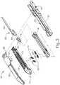
- FIG. 1depicts an exemplary surgical stapling and severing instrument (10) that includes a handle assembly (20), a shaft assembly (30), and an end effector (40).
- End effector (40) and the distal portion of shaft assembly (30)are sized for insertion, in a nonarticulated state as depicted in FIG. 1 , through a trocar cannula to a surgical site in a patient for performing a surgical procedure.
- a trocarmay be inserted in a patient's abdomen, between two of the patient's ribs, or elsewhere.
- instrument (10)is used without a trocar.
- end effector (40) and the distal portion of shaft assembly (30)may be inserted directly through a thoracotomy or other type of incision.
- terms such as “proximal” and “distal”are used herein with reference to a clinician gripping handle assembly (20) of instrument (10).
- end effector (40)is distal with respect to the more proximal handle assembly (20).
- spatial termssuch as “vertical” and “horizontal” are used herein with respect to the drawings.
- surgical instrumentsare used in many orientations and positions, and these terms are not intended to be limiting and absolute.
- handle assembly (20) of the present examplecomprises pistol grip (22), a closure trigger (24), and a firing trigger (26). Each trigger (24, 26) is selectively pivotable toward and away from pistol grip (22) as will be described in greater detail below.
- Handle assembly (20)further includes a removable battery pack (28). These components will also be described in greater detail below.
- handle assembly (20)may have a variety of other components, features, and operabilities, in addition to or in lieu of any of those noted above.
- Other suitable configurations for handle assembly (20)will be apparent to those of ordinary skill in the art in view of the teachings herein.
- shaft assembly (30) of the present examplecomprises an outer closure tube (32), an articulation section (34), and a closure ring (36), which is further coupled with end effector (40).
- Closure tube (32)extends along the length of shaft assembly (30).
- Closure ring (36)is positioned distal to articulation section (34).
- Closure tube (32) and closure ring (36)are configured to translate longitudinally relative to handle assembly (20). Longitudinal translation of closure tube (32) is communicated to closure ring (36) via articulation section (34). Exemplary features that may be used to provide longitudinal translation of closure tube (32) and closure ring (36) will be described in greater detail below.
- Articulation section (34)is operable to laterally deflect closure ring (36) and end effector (40) laterally away from the longitudinal axis (LA) of shaft assembly (30) at a desired angle ( ⁇ ).
- articulationis controlled through an articulation control knob (35) which is located at the proximal end of shaft assembly (30).
- Closure ring (36) and end effector (40)pivot about an axis that is perpendicular to the longitudinal axis (LA) of shaft assembly (30) in response to rotation of knob (35).
- Articulation section (34)is configured to communicate longitudinal translation of closure tube (32) to closure ring (36), regardless of whether articulation section (34) is in a straight configuration or an articulated configuration.
- articulation section (34) and/or articulation control knob (35)may be constructed and operable in accordance with at least some of the teachings of U.S. Pub. No. 2014/0243801 , entitled “Surgical Instrument End Effector Articulation Drive with Pinion and Opposing Racks,” published August 28, 2014, the disclosure of which is incorporated by reference herein; and/or U.S. Pat. App. No. 14/314,125 , entitled “Articulation Drive Features for Surgical Stapler,” filed June 25, 2014, the disclosure of which is incorporated by reference herein; and/or in accordance with the various teachings below.
- Other suitable forms that articulation section (34) and articulation knob (35) may takewill be apparent to those of ordinary skill in the art in view of the teachings herein.
- shaft assembly (30) of the present examplefurther includes a rotation knob (31).
- Rotation knob (31)is operable to rotate the entire shaft assembly (30) and end effector (40) relative to handle assembly (20) about the longitudinal axis (LA) of shaft assembly (30).
- shaft assembly (30)may have a variety of other components, features, and operabilities, in addition to or in lieu of any of those noted above.
- at least part of shaft assembly (30)is constructed in accordance with at least some of the teachings of U.S. Pub. No. 2014/0239038 , entitled "Surgical Instrument with Multi-Diameter Shaft," published August 28, 2014, the disclosure of which is incorporated by reference herein.
- Other suitable configurations for shaft assembly (30)will be apparent to those of ordinary skill in the art in view of the teachings herein.
- end effector (40) of the present exampleincludes a lower jaw (50) and a pivotable anvil (60).
- Anvil (60)includes a pair of integral, outwardly extending pins (66) that are disposed in corresponding curved slots (54) of lower jaw (50).
- Anvil (60)is pivotable toward and away from lower jaw (50) between an open position (shown in FIG. 2 ) and a closed position (shown in FIG. 1 ).
- Use of the term "pivotable”(and similar terms with "pivot" as a base) should not be read as necessarily requiring pivotal movement about a fixed axis.
- anvil (60)pivots about an axis that is defined by pins (66), which slide along curved slots (54) of lower jaw (50) as anvil (60) moves toward lower jaw (50).
- the pivot axistranslates along the path defined by slots (54) while anvil (60) simultaneously pivots about that axis.
- the pivot axismay slide along slots (54) first, with anvil (60) then pivoting about the pivot axis after the pivot axis has slid a certain distance along the slots (54).
- pivotal movementis encompassed within terms such as “pivot,” “pivots,” “pivotal,” “pivotable,” “pivoting,” and the like.
- some versionsmay provide pivotal movement of anvil (60) about an axis that remains fixed and does not translate within a slot or channel, etc.
- lower jaw (50) of the present exampledefines a channel (52) that is configured to receive a staple cartridge (70).
- Staple cartridge (70)may be inserted into channel (52), end effector (40) may be actuated, and then staple cartridge (70) may be removed and replaced with another staple cartridge (70).
- Lower jaw (50)thus releasably retains staple cartridge (70) in alignment with anvil (60) for actuation of end effector (40).
- lower jaw (50)is constructed in accordance with at least some of the teachings of U.S. Pub. No.
- staple cartridge (70) of the present examplecomprises a cartridge body (71) and a tray (76) secured to the underside of cartridge body (71).
- the upper side of cartridge body (71)presents a deck (73), against which tissue may be compressed when anvil (60) is in a closed position.
- Cartridge body (71)further defines a longitudinally extending channel (72) and a plurality of staple pockets (74).
- a staple (90)is positioned in each staple pocket (74).
- a staple driver (75)is also positioned in each staple pocket (74), underneath a corresponding staple (90), and above tray (76).
- staple drivers (75)are operable to translate upwardly in staple pockets (74) to thereby drive staples (90) upwardly through staple pockets (74) and into engagement with anvil (60).
- Staple drivers (75)are driven upwardly by a wedge sled (78), which is captured between cartridge body (71) and tray (76), and which translates longitudinally through cartridge body (71).
- Wedge sled (78)includes a pair of obliquely angled cam surfaces (79), which are configured to engage staple drivers (75) and thereby drive staple drivers (75) upwardly as wedge sled (78) translates longitudinally through cartridge (70). For instance, when wedge sled (78) is in a proximal position, staple drivers (75) are in downward positions and staples (90) are located in staple pockets (74). As wedge sled (78) is driven to the distal position by a translating knife member (80), wedge sled (78) drives staple drivers (75) upwardly, thereby driving staples (90) out of staple pockets (74) and into staple forming pockets (64) that are formed in the underside (65) of anvil (60). Thus, staple drivers (75) translate along a vertical dimension as wedge sled (78) translates along a horizontal dimension.
- staple cartridge (70)is constructed and operable in accordance with at least some of the teachings of U. U.S. Pub. No. 2014/0239042 , entitled “Integrated Tissue Positioning and Jaw Alignment Features for Surgical Stapler,” published August 28, 2014, the disclosure of which is incorporated by reference herein.
- staple cartridge (70)may be constructed and operable in accordance with at least some of the teachings of U.S. Pub. No. 2014/0239044 , entitled “Installation Features for Surgical Instrument End Effector Cartridge,” published August 28, 2014, the disclosure of which is incorporated by reference herein.
- Other suitable forms that staple cartridge (70) may takewill be apparent to those of ordinary skill in the art in view of the teachings herein.
- anvil (60) of the present examplecomprises a longitudinally extending channel (62) and a plurality of staple forming pockets (64).
- Channel (62)is configured to align with channel (72) of staple cartridge (70) when anvil (60) is in a closed position.
- Each staple forming pocket (64)is positioned to lie over a corresponding staple pocket (74) of staple cartridge (70) when anvil (60) is in a closed position.
- Staple forming pockets (64)are configured to deform the legs of staples (90) when staples (90) are driven through tissue and into anvil (60).
- staple forming pockets (64)are configured to bend the legs of staples (90) to secure the formed staples (90) in the tissue.
- Anvil (60)may be constructed in accordance with at least some of the teachings of U.S. Pub. No. 2014/0239042 , entitled “Integrated Tissue Positioning and Jaw Alignment Features for Surgical Stapler,” published August 28, 2014; at least some of the teachings of U.S. Pub. No. 2014/0239036 , entitled “Jaw Closure Feature for End Effector of Surgical Instrument,” published August 28, 2014; and/or at least some of the teachings of U.S. Pub. No. 2014/0239037 , entitled “Staple Forming Features for Surgical Stapling Instrument,” published August 28, 2014, the disclosure of which is incorporated by reference herein.
- Other suitable forms that anvil (60) may takewill be apparent to those of ordinary skill in the art in view of the teachings herein.
- a knife member (80)is configured to translate through end effector (40). As best seen in FIG. 3 , knife member (80) is secured to the distal end of a firing beam (82), which extends through a portion of shaft assembly (30). As best seen in FIG. 2 , knife member (80) is positioned in channels (62, 72) of anvil (60) and staple cartridge (70). Knife member (80) includes a distally presented cutting edge (84) that is configured to sever tissue that is compressed between anvil (60) and deck (73) of staple cartridge (70) as knife member (80) translates distally through end effector (40). As noted above, knife member (80) also drives wedge sled (78) distally as knife member (80) translates distally through end effector (40), thereby driving staples (90) through tissue and against anvil (60) into formation.
- anvil (60)is driven toward lower jaw (50) by advancing closure ring (36) distally relative to end effector (40).
- Closure ring (36)cooperates with anvil (60) through a camming action to drive anvil (60) toward lower jaw (50) in response to distal translation of closure ring (36) relative to end effector (40).
- closure ring (36)may cooperate with anvil (60) to open anvil (60) away from lower jaw (50) in response to proximal translation of closure ring (36) relative to end effector (40).
- closure ring (36) and anvil (60)may interact in accordance with at least some of the teachings of U.S. Pub. No.
- handle assembly (20)includes a pistol grip (22) and a closure trigger (24).
- anvil (60)is closed toward lower jaw (50) in response to distal advancement of closure ring (36).
- closure trigger (24)is pivotable toward pistol grip (22) to drive closure tube (32) and closure ring (36) distally.
- suitable componentsthat may be used to convert pivotal movement of closure trigger (24) toward pistol grip (22) into distal translation of closure tube (32) and closure ring (36) relative to handle assembly (20) will be apparent to those of ordinary skill in the art in view of the teachings herein.
- instrument (10)provides motorized control of firing beam (82).
- instrument (10)includes motorized components that are configured to drive firing beam (82) distally in response to pivoting of firing trigger (26) toward pistol grip (22).
- a motor(not shown) is contained in pistol grip (22) and receives power from battery pack (28). This motor is coupled with a transmission assembly (not shown) that converts rotary motion of a drive shaft of the motor into linear translation of firing beam (82).
- the features that are operable to provide motorized actuation of firing beam (82)may be configured and operable in accordance with at least some of the teachings of U.S. Pat. No.
- instrument (10)may be configured and operable in accordance with any of the various references cited herein. Additional exemplary modifications that may be provided for instrument (10) will be described in greater detail below. Various suitable ways in which the below teachings may be incorporated into instrument (10) will be apparent to those of ordinary skill in the art. Similarly, various suitable ways in which the below teachings may be combined with various teachings of the references cited herein will be apparent to those of ordinary skill in the art. It should therefore be understood that the teachings below may be readily incorporated into the various instruments taught in the various references that are cited herein. It should also be understood that the below teachings are not limited to instrument (10) or devices taught in the references cited herein.
- end effector (40)may be desirable to equip end effector (40) with a buttress material to reinforce the mechanical fastening of tissue provided by staples (90).
- a buttressmay prevent the applied staples (90) from pulling through the tissue and may otherwise reduce a risk of tissue tearing at or near the site of applied staples (90).
- a buttressmay provide various other kinds of effects such as spacing or gap-filling, administration of therapeutic agents, and/or other effects.
- a buttressmay be provided on deck (73) of staple cartridge (70).
- a buttressmay be provided on the surface of anvil (60) that faces staple cartridge (70).
- first buttressmay be provided on deck (73) of staple cartridge (70) while a second buttress is provided on anvil (60) of the same end effector (40).
- a buttressmay take will be described in greater detail below.
- Various ways in which a buttress may be secured to a staple cartridge (70) or an anvil (60)will also be described in greater detail below.
- FIG. 4shows an exemplary pair of buttress assemblies (100, 110) with a basic composition.
- Buttress assembly (100) of this examplecomprises a buttress body (102) and an upper adhesive layer (104).
- buttress assembly (110)comprises a buttress body (112) and a lower adhesive layer (114).
- each buttress body (102, 112)comprises a strong yet flexible material configured to structurally support a line of staples (90).
- each buttress body (102, 112)may comprise a woven mesh of polyglactin 910 material by Ethicon, Inc. of Somerville, New Jersey.
- each buttress body (102, 112)may take any other suitable form and may be constructed of any other suitable material(s).
- each buttress body (102, 112)may comprise one or more of the following: NEOVEIL absorbable PGA felt by Gunze Limited, of Kyoto, Japan; SEAMGUARD polyglycolic acid:trimethylene carbonate (PGA:TMC) reinforcement material by W.L.
- each buttress body (102, 112)will be apparent to those of ordinary skill in the art in view of the teachings herein.
- each buttress body (102, 112)may comprise a material including, for example, a hemostatic agent such as fibrin to assist in coagulating blood and reduce bleeding at the severed and/or stapled surgical site along tissue (90).
- a hemostatic agentsuch as fibrin
- each buttress body (102, 112)may comprise other adjuncts or hemostatic agents such as thrombin may be used such that each buttress body (102, 112) may assist to coagulate blood and reduce the amount of bleeding at the surgical site.
- Other adjuncts or reagents that may be incorporated into each buttress body (102, 112)may further include but are not limited to medical fluid or matrix components.
- each buttress body (102, 112)may be constructed in accordance with at least some of the teachings of U.S. Patent Pub. No. 2012/0241493 , entitled “Tissue Thickness Compensator Comprising Controlled Release and Expansion,” published September 27, 2012, the disclosure of which is incorporated by reference herein; U.S. Patent Pub. No. 2013/0068816 , entitled “Surgical Instrument and Buttress Material,” published March 21, 2013, the disclosure of which is incorporated by reference herein; U.S. Patent Pub. No. 2013/0062391 , entitled “Surgical Instrument with Fluid Fillable Buttress,” published March 14, 2013, the disclosure of which is incorporated by reference herein; U.S. Patent Pub. No.
- 2013/0068820entitled “Fibrin Pad Matrix with Suspended Heat Activated Beads of Adhesive,” published March 21, 2013, the disclosure of which is incorporated by reference herein;
- U.S. Patent Pub. No. 2013/0082086entitled “Attachment of Surgical Staple Buttress to Cartridge,” published April 4, 2013, the disclosure of which is incorporated by reference herein;
- U.S. Patent Pub. No. 2013/0037596entitled “Device for Applying Adjunct in Endoscopic Procedure,” published February 14, 2013, the disclosure of which is incorporated by reference herein;
- 2013/0062393entitled “Resistive Heated Surgical Staple Cartridge with Phase Change Sealant,” published March 14, 2013, the disclosure of which is incorporated by reference herein;
- U.S. Patent Pub. No. 2013/0075446entitled “Surgical Staple Assembly with Hemostatic Feature,” published March 28, 2013, the disclosure of which is incorporated by reference herein;
- U.S. Patent Pub. No. 2013/0062394entitled “Surgical Staple Cartridge with Self-Dispensing Staple Buttress,” published March 14, 2013, the disclosure of which is incorporated by reference herein;
- 2013/0075445entitled “Anvil Cartridge for Surgical Fastening Device,” published March 28, 2013, the disclosure of which is incorporated by reference herein;
- U.S. Patent Pub. No. 2013/0075447entitled “Adjunct Therapy for Applying Hemostatic Agent,” published March 28, 2013, the disclosure of which is incorporated by reference herein;
- U.S. Patent Pub. No. 2013/0256367entitled “Tissue Thickness Compensator Comprising a Plurality of Medicaments,” published October 3, 2013, the disclosure of which is incorporated by reference herein;
- adhesive layer (104)is provided on buttress body (102) in order to adhere buttress body (102) to underside (65) of anvil (60).
- adhesive layer (114)is provided on buttress body (112) in order to adhere buttress body (112) to deck (73) of staple cartridge (70).
- Adherence of the buttress body (102) to underside (65) of anvil (60) or to deck (73) of staple cartridge (70)can occur through a variety of mechanisms including but not limited to a pressure sensitive adhesive.
- each adhesive layer (104, 114)comprise a pressure sensitive adhesive material. Examples of various suitable materials that may be used to form adhesive layers (104, 114) are disclosed in U.S. Patent App. No.
- any other suitable materialsmay be used.
- the term "adhesive,” as used hereinmay include (but is not limited to) tacky materials and also materials that are pliable or wax-like and adhere to a complex geometry via deformation and conformance. Some suitable adhesives may provide such pliability to adhere to a complex geometry via deformation and conformance without necessarily providing a high initial tack. In some instances, adhesives with lower tackiness may be removed more cleanly from surfaces.
- Suitable materials that may be used to form adhesive layers (104, 114)will be apparent to those of ordinary skill in the art in view of the teachings herein.
- a buttress assembly (100, 110)may include a layer (104, 114) of adhesive material (or other form of adhesive material) that adheres buttress body (102, 112) to either underside (65) of anvil (60) or deck (73) of staple cartridge (70).
- adhesive materialor other form of adhesive material
- Such an adhesive materialmay provide proper positioning of buttress body (102, 112) before and during actuation of end effector (40); then allow buttress body (102, 112) to separate from end effector (40) after end effector (40) has been actuated, without causing damage to buttress body (102, 112) that is substantial enough to compromise the proper subsequent functioning of buttress body (102, 112).
- FIGS. 5A-5Cshow a sequence where an end effector (40) that has been loaded with buttress assemblies (100, 110) is actuated to drive staples (90) through two apposed layers of tissue (T 1 , T 2 ), with buttress assemblies (100, 110) being secured to the same layers of tissue (T 1 , T 2 ) by staples (90).
- FIG. 5Ashows layers of tissue (T 1 , T 2 ) positioned between anvil (60) and staple cartridge (70), with anvil (60) in the open position.
- Buttress assembly (100)is adhered to the underside (65) of anvil (60) via adhesive layer (104); while buttress assembly (110) is adhered to deck (73) of staple cartridge (70) via adhesive layer (114).
- a series of staples (90)will similarly capture and retain buttress assemblies (100, 110) against layers of tissue (T 1 , T 2 ), thereby securing buttress assemblies (100, 110) to tissue (T 1 , T 2 ) as shown in FIG. 6 .
- end effector (40)is pulled away from tissue (90) after deploying staples (90) and buttress assemblies (100, 110), buttress assemblies (100, 110) disengage end effector), such that buttress assemblies (100, 110) remain secured to tissue (T 1 , T 2 ) with staples (90).
- Buttress tissue (T 1 , T 2 )thus provide structural reinforcement to the lines of staples (90).
- knife member (80)also cuts through a centerline of buttress tissue assemblies (100, 110), separating each buttress assemblies (100, 110) into a corresponding pair of sections, such that each section remains secured to a respective severed region of tissue (T 1 , T 2 ).
- buttress assembly (100)is sized to span across the full width of underside (65), such that buttress assembly (100) spans across channel (62).
- knife member (80)cuts through buttress assembly (100) during actuation of end effector (40) as described above.
- buttress assembly (100)is provided in two separate, laterally spaced apart portions, with one portion being disposed on underside (65) on one side of channel (62) and another portion being disposed on underside (65) on the other side of channel (62). In such versions, buttress assembly (100) does not span across channel (62), such that knife member (80) does not cut through buttress assembly (100) during actuation of end effector (40).
- buttress assembly (110)may be sized to span across the full width of deck (73), such that buttress assembly (110) spans across channel (72), and such that knife member (80) cuts through buttress assembly (110) during actuation of end effector (40) as described above.
- buttress assembly (110)may be provided in two separate, laterally spaced apart portions, with one portion being disposed on deck (73) on one side of channel (72) and another portion being disposed on deck (73) on the other side of channel (72), such that buttress assembly (110) does not span across channel (72), and such that knife member (80) does not cut through buttress assembly (110) during actuation of end effector (40).
- FIGS. 7-8show an exemplary buttress assembly (200) that comprises a buttress body (202), a first adhesive layer (204) laid over buttress body (202), and a second adhesive layer (206) laid over first adhesive layer (204). It should be understood that, with buttress body (202) at the bottom of buttress assembly (200), buttress assembly (200) is analogous to buttress assembly (100) described above and may be similarly secured to underside (65) of anvil (60).
- buttress assembly (200)may be flipped upside-down for an arrangement where buttress assembly (200) would be secured to deck (73) of staple cartridge (70).
- second adhesive layer (206)would be at the bottom
- first adhesive layer (204)would be laid over second adhesive layer (206)
- buttress body (202)would be laid over first adhesive layer (204).
- Buttress body (202)may be constructed and operable just like buttress bodies (102, 112) described above. Moreover, buttress body (202) may be constructed and operable in accordance with at least some of the teachings of U.S. Patent App. No. 14/667,842 , entitled “Method of Applying a Buttress to a Surgical Stapler," filed March 25, 2015, the disclosure of which is incorporated by reference herein. Other suitable forms that buttress body (202) may take will be apparent to those of ordinary skill in the art in view of the teachings herein.
- First adhesive layer (204)is formed of an adhesive material that is different from the adhesive material forming second adhesive layer (206).
- first adhesive layer (204)is formed of a material that has greater pliability and tackiness than the material forming second adhesive layer (206).
- second adhesive layer (206)serves as a protectant for first adhesive layer (204).
- second adhesive layer (206)may protect first adhesive layer (204) from humidity, temperature fluctuations, and/or other environmental conditions that may be encountered during shipment and/or storage of buttress assembly (200).
- second adhesive layer (206)may be more resistant to moisture and/or temperature than first adhesive layer (206).
- second adhesive layer (206)is replaced with a non-adhesive protective layer.
- second adhesive layer (206)may be replaced by a film or other structure that is biocompatible and bioabsorbable, dissolvable, or otherwise capable of temporarily confining the material forming first adhesive layer (204) (e.g., to prevent first adhesive layer from seeping, migrating, or otherwise flowing out of buttress assembly (200) during storage, shipping, handling before surgery, etc.).
- first adhesive layere.g., to prevent first adhesive layer from seeping, migrating, or otherwise flowing out of buttress assembly (200) during storage, shipping, handling before surgery, etc.
- both adhesive layers (204, 206)may nevertheless cooperate to adhere buttress assembly (200) to underside (65) of anvil (60).
- second adhesive layer (206)is sprayed onto first adhesive layer (204) while first adhesive layer is maintained at a temperature and humidity level that keeps first adhesive layer (204) solid.
- first adhesive layeris maintained at a temperature and humidity level that keeps first adhesive layer (204) solid.
- the combination of different adhesive layers (204, 206)may be more soluble against anvil (60) and/or less sticky against anvil (60) than just a single adhesive layer (204) might be. This may prevent an undesirable buildup of adhesive material on underside (65) of anvil (60) as a series of buttress assemblies (200) are applied to underside (65) for a series of end effector (40) actuations during a surgical procedure.
- adhesive layers (204, 206)may provide different ratios of two molecular weight blends in different layers (204, 206).
- molecular weightmeans weight average molecular weight herein.
- adhesive layers (204, 206)may have cross-linking differences and/or come from different families of adhesive.
- adhesive layers (204, 206) formed by higher molecular weight poloxamersmay be stiffer and less prone to flow with temperature.
- using a poloxamer blend with higher molecular weight to form adhesive layer (206)may contain a lower molecular weight material forming adhesive layer (204), even if adhesive layer (204) becomes fluid with temperature. Materials with higher degrees of cross-linking may have higher transition temperatures and therefore flow less at temperature extremes.
- An example of different familiescould be a poloxamer blend in adhesive layer (204) with a thin layer of PCL/PGA co-ploymer sprayed onto adhesive layer (204) to form adhesive layer (206).
- first adhesive layer (204)may be configured and operable in accordance with at least some of the teachings of U.S. Pat. App. No. 14/926,045 [ATTORNEY DOCKET NO. END7809USNP.0630312], entitled “Surgical Stapler Buttress Assembly with Humidity Tolerant Adhesive,” filed on even date herewith, the disclosure of which is incorporated by reference herein; U.S. Pat. App. No. 14/926,057 [ATTORNEY DOCKET NO. END7810USNP.0630307], entitled “Surgical Stapler Buttress Assembly with Adhesion to Wet End Effector,” filed on even date herewith, the disclosure of which is incorporated by reference herein; and/or any other references cited herein.
- FIGS. 9-10show an exemplary alternative buttress assembly (300) where the outer edges of a first adhesive layer (304) are covered by downwardly projecting regions (308) of a second adhesive layer (306). Downwardly projecting regions (308) extend along the full width and the full length of firs adhesive layer (304) in this example. Downwardly projecting regions (308) also extend downwardly into contact with the upper surface of buttress body (302). Buttress body (302) and second adhesive layer (306) thus cooperate to completely encapsulate first adhesive layer (304).
- Buttress body (302), first adhesive layer (304), and second adhesive layer (306)may be otherwise identical to buttress body (202), first adhesive layer (204), and second adhesive layer (206) as described above.
- Other suitable ways in which adhesive layers (304, 306) may be configured and arranged in relation to a buttress body (302)will be apparent to those of ordinary skill in the art in view of the teachings herein.
- any of the various buttress assemblies described hereinmay be further constructed and operable in accordance with at least some of the teachings of U.S. Patent App. No. 14/667,842 , entitled “Method of Applying a Buttress to a Surgical Stapler,” filed March 25, 2015, the disclosure of which is incorporated by reference herein.
- the humidity tolerant adhesive materialsfor a buttress body (102, 202, 302, 112) comprise bioabsorbable polymers.
- Various physiomechanical properties of polymersmay be modified in order to provide different adhesive properties.
- Such variable characteristicsinclude but are not limited to copolymer composition, polymer architecture (e.g., random vs. block copolymers and/or branching), glass transition temperature (Tg), molecular weight (number average or weight average molecular weight), inherent viscosity (IV), crystallinity, sequence distribution, copolymer chain composition, melting temperature (Tm), surface tension and rheological properties.
- Glass transition temperature (Tg)is the temperature at which the mechanical properties of a copolymer change dramatically from a flowable adhesive to a brittle plastic. It may thus be of importance that the glass transition temperature (Tg) is sufficiently below the operating temperature of the adhesive in order to allow for polymer chain mobility.
- the glass transition temperature (Tg)is lower than the melting point of the crystalline form of the same copolymer.
- the glass transition temperature (Tg)may be indicative of how the polymer behaves under ambient conditions.
- the glass transition temperature (Tg)can be effected by composition, polymer chain configuration and stiffness, molecular weight, viscosity, shear modulus, heat capacity, thermal expansion, cross-linking and other factors. It is therefore possible to have a relatively low glass transition temperature (Tg) material composition that does not always correspond to low molecular weight or low inherent viscosity (IV).
- the melting temperature of a polymermay be referred to as the "first-order transition," which is where the polymer changes from a solid to liquid.
- Crystalline polymershave a true melting point, which is the temperature at which the crystallites melt and the total mass of plastic becomes amorphous.
- Amorphous polymersdo not have a true melting point, but they do have a first-order transition wherein their mechanical behavior transitions from a rubbery nature to viscous rubbery flow.
- Suitable polymers for use in forming adhesive layers (104,204,304, 114)may have a percentage of crystallinity making them semi-crystalline, thus having both amorphous and crystalline domains.
- the melting point of the polymermay be sufficiently high above the operating temperature of the adhesive to maintain cohesive strength and provide dimensional stability of the applied adhesive.
- Inherent viscosity (IV)reflects a measurement of molecular size. It is based on the flow time of a polymer solution through small capillary channels over time. The inherent viscosity (IV) and molecular weight of a polymer are related, but that relational agreement is different for each copolymer composition. For instance, the correlation of inherent viscosity (IV) to molecular weight may be logarithmic with only a small midsection of the curve being linear. This logarithmic correlation may differ as the copolymer composition differs. It is not necessarily required to have a low molecular weight copolymer in order to manifest adhesive and malleable properties. Low molecular weight copolymers may also have shortened degradation cycles and reduced structural strength.
- the ideal adhesion film or adhesive substrate to use in adhesive layersmay have higher molecular weight and low inherent viscosity (IV) to be both strong and adhesive. This may be achieved, for example, by the introduction of polymer branching.
- the molecular weight of the adhesivemay need to be high enough to provide mechanical strength to the adhesive to avoid cohesive failure, but also sufficiently low enough that it can be cleared from the body through degradation in an acceptable amount of time.
- Further important properties of the polymersinclude their surface tension and rheological properties. If there is a sufficiently large mismatch between the surface tension of the adhesive and the surfaces to be adhered to, adhesion may be energetically unfavorable. Similarly, the rheological properties of the polymer such as bulk moduli may need to be such that the polymer can flow to conform to the surface topography of deck (73) or underside (65), while simultaneously providing enough integrity to maintain cohesive strength and to resist shearing off and/or peeling off of end effector (40).
- the humidity tolerant adhesive materialsmay be malleable.
- Malleable humidity tolerant adhesivesmay be highly viscous yet flowable at room temperature.
- a malleable humidity tolerant adhesivemay, in response to pressure being applied to it, take the form of a surface with which it is engaged. In other words, if a malleable humidity tolerant adhesive is pressed against deck (73) of staple cartridge (70), the adhesive may take the form of the one or more features of the deck (73) that it the adhesive is pressed against. Similarly, if a malleable humidity tolerant polymer adhesive is pressed against underside (65) of anvil (60), the adhesive may take the form of the one or more features of underside (65) that the adhesive is pressed against.
- the malleable humidity tolerant adhesivemay adhere to the geometry, and may further provide re-applicable attachment. If the desired positioning of buttress assembly (100, 110) on deck (73) or underside (65) is not achieved, the malleable humidity tolerant adhesive may permit buttress assembly (100, 110) to be removed, repositioned, and re-adhered to deck (73) or underside (65). It should be understood that the humidity tolerant adhesives may be malleable at room temperature, such that additional heating or other treatment is not necessary in order to provide malleability.
- Providing the humidity tolerant adhesive material in the form of a malleable polymermay minimize the impact of fluids and debris on the adhesion of buttress assembly (100, 110) to deck (73) of staple cartridge (70) or underside (65) of anvil (60).
- the malleable humidity tolerant adhesive materialmay also be hydrophilic (e.g., at least in certain regions of buttress assembly (100, 110)), encouraging adhesion in a wet environment.
- adhesive layer (104, 114) of buttress assembly (100)may include a combination of adhesive material and hydrophobic material in respective localized regions. The hydrophobic material may drive fluids out of the adhesion areas, thereby improving adhesion at the localized regions of adhesive material.
- the humidity tolerant adhesive materialmay be combined with a buttress body (102,112) as disclosed in U.S. Patent App. No. 14/667,842 , entitled “Method of Applying a Buttress to a Surgical Stapler,” filed March 25, 2015, the disclosure of which is incorporated by reference herein.
- the humidity tolerant adhesive materialsmay be extrudable.
- the extrudable adhesivemay be extruded through a die that may be positioned directly next to or adjacent to the extruder.
- a melt pumpmay be used between the die and extruder.
- the diemay be used to form an extrudate that is generally planar and continuous or to form discrete deposits (e.g., rod-shaped deposits) on the surface of a buttress assembly (100, 110) before it is pressed against a deck (73) of staple cartridge (70) or pressed against the underside of an anvil (60).
- the humidity tolerant adhesive materialsfor a buttress body (102, 202, 302, 112) comprise polymers having a general A-B-A block configuration.
- the A-B-A block polymerscomprise by the percentage of their molecular weight: from about 1% to about 50%, or more particularly from about 5% to about 30% of A polymer blocks; and from about 50% to about 99%, or more particularly from about 70% to about 95%, of B polymer blocks.
- the A polymer blocksare biodegradable, bioabsorbable, highly crystalline segments, which are homopolymers that may be characterized by a relatively high glass transition temperature (Tg) and/or a relatively high crystallinity.
- Tgglass transition temperature
- the A homopolymersmay be characterized by a glass transition temperature (Tg) of at least about 0°C, preferably at least about 21°C (i.e., room temperature).
- Tgglass transition temperature
- the A homopolymersmay be characterized by a crystallinity as measured by X-ray diffraction of at least about 30%, preferably at least about 40%, or more preferably at least about 45%.
- the A homopolymersmay have a molecular weight of at least about 5 kDa.
- Such exemplary A homopolymersmay further be characterized by a melting temperature (Tm) of at least about 50°C, preferably at least about 60°C, and more preferably at least about 70°C.
- Exemplary A homopolymersmay be selected from the group of: poly(L-lactide) (PLLA); poly(caprolactone) (PCL); polyglycolide (PGA); poly(3-hydroxybutyrate) (PH 3 B); poly(3-hydroxyvalerate) (PHV); and poly(p-dioxanone) (PPDO). It may be difficult to synthesize 100% A homopolymers.
- the A homopolymersmay contain a small percentage of residual B monomers.
- exemplary A homopolymersmay contain a small percentage (e.g., up to about 10% by weight) of B monomers.
- the B polymer blocksare biodegradable, bioabsorbable homopolymers or co-polymers, which are predominantly amorphous and may be characterized by a relatively low to moderate glass transition temperature (Tg).
- Tgglass transition temperature
- the B polymers as homopolymers or co-polymersmay be characterized by glass transition temperature (Tg) of at least about -40°C, more particularly at least about -30°C, and more particularly at least about -20 °C.
- Tgglass transition temperature
- the B homopolymers or co-polymersmay be characterized by a crystallinity as measured by X-ray diffraction of at most about 25%, more particularly at most about 10%, or more particularly at most about 5%.
- the B polymers as homopolymers or co-polymersmay have a molecular weight of from about 20 to about 80 kDa, more particularly from about 30 to about 70 kDa, and more particularly, from about 40 to about 65 kDa.
- Exemplary B homopolymers or co-polymerscomprise monomers selected from the group consisting of: caprolactone (CL), L-Lactide (LLA), D,L-Lactide ((D,L)LA), Glycolide (GA), Polydioxanone (PDO), Trimethylene carbonate (TMC), sebacic acid (SA), 1,6-bis(carboxyphenoxy)hexane (CPH), and combinations thereof.
- the humidity tolerant adhesive materials having a general A-B-A block configurationmay be blended with a tackifying agent to provide for an extrudable adhesive.
- a tackifying agentmay be manufactured using hot melt extrusion.
- the A-B-A block polymermay be fed into a hot melt compounding twin-screw extruder. Once the A-B-A block polymer is sufficiently masticated and melted, the tackifying agent is added into the extruder.
- additional compoundsmay be added in one or more additional steps to the extruder. Such additional compounds may selected from the group consisting of: plasticizing molecules; preservatives (e.g. antioxidants); fillers; and combinations thereof.
- the resulting adhesivemay be fed through an extruder die and produced as a stand-alone flexible film that is then applied to a buttress body (102, 112).
- the resulting adhesivemay be fed through an extruder die and deposited directly onto a buttress body (102, 112).
- the adhesivemay then be annealed to obtain any necessary phase separation at, near or above the A-block melting temperature, T m .
- the resulting adhesivemay be sterilized, such as by treating it with ethylene oxide at a high temperature.
- the tackifying agentmay comprise a substantially amorphous biodegradable, bioabsorbable polymer with a molecular weight below the entanglement molecular weight.
- the tackifying agentmay have a glass transition above about 0 °C, more particularly above about 20 °C.
- the tackifying agentmay comprise a random copolymer of poly(L-lactide)-co-polyglycolide (PLGA) having a molecular weight of from about 1 to about 8 kDA, more particularly from about 1.5 to about 5 kDa.
- an extrudable hot melt adhesivecomprises ratios of polymer A-B-A and tackifying agent such that the glass transition of the blend ranges from about -5°C to about 15°C, more particularly from 0°C to about 10 °C.
- the rheological properties of the polymersuch as bulk moduli need to be such that the polymer can flow to conform to the surface topography of deck (73) or underside (65), while at the same time, providing enough integrity to maintain cohesive strength and resisting shearing off and/or peeling off of end effector (40).
- the humidity tolerant adhesive materialsfor a buttress body (102, 202, 302, 112) comprise polymers having a general A-B-C block terpolymer configuration, in which the C polymer block comprises a hydrophilic polymer.
- the humidity tolerant adhesives comprising hydrophilic polymersmay have better wet surface retention characteristics than adhesives comprising only hydrophobic polymers.
- the A-B-C block terpolymersmay be combined with a water sorbent.
- Useful water sorbentsmay be selected from the group consisting of: carboxymethyl cellulose (CMC); polyvinylpyrrolidine (PVP); gelatin; hyaluronan; and combinations thereof.
- the A-B-C block terpolymersmay be combined with water sorbent such that the resulting mixture comprises by its weight percentage from about 1% to about 60%, preferably from about 20% to about 40%, of the water sorbent.
- the A polymer blocksare biodegradable, bioabsorbable, non-elastic, highly crystalline segments, which are homopolymers that may be characterized by a relatively high glass transition temperature (Tg) and/or a relatively high crystallinity.
- Tgglass transition temperature
- the A homopolymersmay be characterized by a glass transition temperature (Tg) of at least about 0°C, more particularly at least about 21°C (i.e., room temperature).
- Tgglass transition temperature
- the A homopolymersmay be characterized by a crystallinity as measured by X-ray diffraction of at least about 30%, more particularly at least about 40%, or more particularly at least about 45%.
- the A homopolymersmay have a molecular weight of at least about 5 kDa.
- Such exemplary A homopolymersmay further be characterized by a melting temperature (Tm) of at least about 50°C, more particularly at least about 60°C, and more particularly at least about 70°C.
- Exemplary A homopolymersmay be selected from the group of: poly(L-lactide) (PLLA); poly(caprolactone) (PCL); polyglycolide (PGA); poly(3-hydroxybutyrate) (PH 3 B); poly(3-hydroxyvalerate) (PHV); and poly(p-dioxanone) (PPDO). It may be difficult to synthesize 100% A homopolymers.
- the A homopolymersmay thus contain a small percentage of residual B monomers.
- exemplary A homopolymersmay contain a small percentage (e.g., up to about 10% by weight) of B monomers.
- the B polymer blocksare biodegradable, bioabsorbable, elastomeric homopolymers or co-polymers, which are predominantly amorphous and may be characterized by a relatively low to moderate glass transition temperature (Tg).
- Tgglass transition temperature
- the B polymers as homopolymers or co-polymersmay be characterized by glass transition temperature (Tg) of at least about -40°C, more particularly at least about -30°C, and more particularly at least about -20 °C.
- Tgglass transition temperature
- the B homopolymers or co-polymersmay be characterized by a crystallinity as measured by X-ray diffraction of at most about 25%, more particularly at most about 10%, or more particularly at most about 5%.
- the B polymers as homopolymers or co-polymersmay have a molecular weight of from about 20 to about 80 kDa, more particularly from about 30 to about 70 kDa, and more particularly, from about 40 to about 65 kDa.
- the B polymers as homopolymersmay have an entanglement molecular weight of from about 3 to 4 kDa.
- Exemplary B homopolymers or co-polymerscomprise monomers selected from the group consisting of: caprolactone (CL), L-Lactide (LLA), D,L-Lactide ((D,L)LA), Glycolide (GA), Polydioxanone (PDO), Trimethylene carbonate (TMC), sebacic acid (SA), 1,6-bis(carboxyphenoxy)hexane (CPH), and combinations thereof.
- B polymers or co-polymersmay be selected from the group of: caprolactone-co-glycolide (CAP-co-GLY); poly(L-lactide)-co-glycolide (PLGA); poly(D,L-lactide) (P(D,L)LA); poly(caprolactone)-co-glycolide (PCL-co-GA); poly[(1,6-bis(p-carboxyphenoxy)hexane)-co-sebacic acid (PCPH-co-SA); poly(trimethylene carbonate) (PTMC); poly(trimethylene carbonate)-co-glycolide (PTMC-co-GA; and poly(trimethylene carbonate)-co-caprolactone (PTMC-co-CL).
- CAP-co-GLYcaprolactone-co-glycolide
- PLGApoly(L-lactide)-co-glycolide
- P(D,L)LA)poly(caprolactone)-co-gly
- the C polymer blocksare biodegradable, bioabsorbable, hydrophilic homopolymers or co-polymers and may be characterized by miscibility with water at 37°C.
- Exemplary C homopolymers and co-polymersmay be selected from the group of: polyethylene oxide (PEO); polyethylene oxide-co-polypropylene oxide (PEO-co-PPO); polyethylene oxide-co-polysulfone (PEO-co-PSO); polyvinylpyrrolidine (PVP); polyacrylic acid (PAA); and polyvinyl alcohol (PVOH).
- Ais glycolide (GLY)
- Bis a co-polymer of caprolactone-glycolide (CAP-co-GLY)
- Cis polyethylene oxide (PEO).
- a buttress body (102, 112)with one or more humidity tolerant adhesive materials that will at least temporarily adhere to a wet end effector (40), particularly when it is being used intraoperatively.
- humidity tolerant adhesive materialsmay provide for temporary attachment of a buttress body (102, 112) to the wet deck (73) of staple cartridge (70) or the wet underside (65) of anvil (60).
- a humidity tolerant adhesive materialis defined herein as an adhesive material that holds a buttress body (102, 112) in place on an anvil (60) or staple cartridge (70) for at least five minutes in an environment of 100% relative humidity (e.g., in a patient's body, at a normal body temperature of approximately 37°C), preferably after the buttress body (102, 112) has been exposed to a relative humidity of from about 20% to about 60% for up to one hour at room temperature (e.g., between approximately 20°C and approximately 22°C).
- a humidity tolerant adhesive materialmay hold a buttress body (102, 112) in place on an anvil (60) or staple cartridge (70) for at least ten minutes in an environment of 100% relative humidity (e.g., in a patient's body, at a normal body temperature of approximately 37°C), preferably after the buttress body (102, 112) has been exposed to a relative humidity of from about 20% to about 60% for up to one hour at room temperature (e.g., between approximately 20°C and approximately 22°C).
- a pressure sensitive humidity tolerant adhesive materialis defined herein as a humidity tolerant adhesive material that can be transferred from a delivery device onto an anvil (60) or staple cartridge (70) by the pressure respectively exerted by the anvil (60) or staple cartridge (70).
- Adhesive layers (104, 114)respectively provide for temporary attachment of the buttress bodies (102, 112) to underside (65) of anvil (60) and deck (73) of staple cartridge (70). It should be understood that the humidity tolerant adhesive material need not necessarily constitute a separate adhesive layer (104, 114) that is discretely identifiable as being different from a layer defined by buttress body (102, 112). Examples of humidity tolerant adhesive materials that may be otherwise integrated onto or into a buttress body (102, 112) are described in further detail below.
- the humidity tolerant adhesive materialsfor a buttress body (102, 112)
- a buttress body (102, 112)comprise polymers that are either bioabsorbable or of a molecular weight that is sufficiently low so as to be cleared from the patient's body (e.g., less than approximately 30,000 KDa).
- Various physiomechanical properties of polymersmay be modified in order to provide different adhesive properties. Such variable characteristics include but are not limited to the following: copolymer composition; copolymer architecture (e.g., random vs.
- some exemplary humidity tolerant adhesive materialsmay comprise polymers that are combined with sorbents.
- Useful sorbentsmay be selected from the group consisting of: polysaccharides such as cellulose; cellulose derivatives, e.g., sodium carboxymethylcellulose (Na-CMC); starch; starch derivates; natural gums, e.g., agar and alginates; chitosan; pectin; gelatin; and combinations thereof.
- a hydrocolloid of one or more sorbentsmay be mixed with the polymers.
- the humidity tolerant adhesive materialcomprises a blend of sorbent and polymer in a ratio in a range of 70:30 sorbent to polymer, more particularly in a range of 50:50 sorbent to polymer, more preferably in a range of 10:90 sorbent to polymer.
- sorbentsmay act to absorb moisture away from the surface interface between the humidity tolerant adhesive material and the surface to which it is adhered (e.g., a wet end effector (40)), and to maintain the adherence of the buttress body (102, 112) to said surface until such time as the buttress body (102, 112) is deployed or released from end effector (40).
- Glass transition temperatureis the temperature at which the mechanical properties of a copolymer change dramatically from a flowable adhesive to a brittle plastic. It may thus be of importance that the glass transition temperature (Tg) is sufficiently below the operating temperature of the humidity tolerant adhesive material in order to allow for sufficient polymer chain mobility.
- the melting temperature (Tm) of a polymermay be referred to as the "first-order transition,” which is where the polymer changes state from solid to liquid. Crystalline polymers have a true melting point, which is the temperature at which the crystallites melt and the total mass of plastic becomes liquid.
- Amorphous polymersdo not have a true melting point, but they do have a first-order transition wherein their mechanical behavior transitions from a rubbery nature to viscous rubbery flow.
- Suitable polymers for use in humidity tolerant adhesive materialsmay be semi-crystalline, i.e., they may have both amorphous and crystalline segments.
- Suitable polymersmay have a melting point that is sufficiently above the operating temperature of the humidity tolerant adhesive material to maintain cohesive strength and to provide dimensional stability of the applied humidity tolerant adhesive material.
- the molecular weight of non-bioabsorbable polymersshould be high enough to provide mechanical strength to the resulting adhesive material in order to avoid cohesive failure, yet low enough that they can be cleared by the patient's body. In the case of biodegradable polymers, an upper limit on molecular weight may not be required to provide polymer breakdown products are small enough to be cleared by the patient's body.
- solubility or dissolution rate of polymers in the aqueous environmentsdepend upon a number of polymer characteristics including, but not limited to: polymer composition; polymer architecture; degree of cross-linking; block length; crystallinity; molecular weight; branching; and combinations thereof.
- the surface tension and rheology of polymers present in a humidity tolerant adhesive materialmay also impact its adhesive properties. For example, if there is a sufficiently large mismatch between the surface tension of the polymers and the surfaces to which it will adhere, adhesion between the two may be energetically unfavorable. Similarly, the rheological properties of the polymer such as bulk modulus may be such that the humidity tolerant adhesive material can flow to conform to the surface topography of the end effector (40), while at the same time providing sufficient integrity to maintain cohesive strength and resist shearing and peeling of the buttress body (102, 112) from the end effector (40).
- the humidity tolerant adhesive materialsfor a buttress body (102, 112) may comprise a blend of "plastic fats", more particularly, poloxamers.
- the blend of poloxamersmay comprise a blend of poloxamers selected from the group consisting of: poloxamer 188, for example Kolliphor® P188 from BASF (Florham Park, NJ); Synperonic® PE/P84 from Croda Inc.
- poloxamer 124for example Pluronic® L44 from BASF (Florham Park, NJ); poloxamer 407, for example Pluronic® F-127 from BASF (Florham Park, NJ); and combinations thereof.
- the poloxamersare of National Formulary grade.
- the resulting poloxamer-based humidity tolerant adhesive materialsmay be putty-like materials with a relatively low crystallinity and low glass transition temperature (Tg).
- a poloxamer blend having a slower dissolution ratewhich may desirably provide for humidity tolerant adhesive materials having a greater humidity (i.e., wetness) tolerance.
- a buttress body (102, 112), to which poloxamer-based adhesive materials have been appliedmay desirably remain adhered to a wet end effector (40) of a surgical stapling instrument (10) during a surgical procedure until such time as buttress body (102, 112) is deployed.
- the humidity tolerant adhesive materialscomprise a poloxamer blend of poloxamer 188 and Synperonic® PE/P84 in a molar ratio in the range of from 1:3 to 1:4 of poloxamer 188 to Synperonic® PE/P84.
- humidity tolerant adhesive materialscomprise a poloxamer blend of poloxamer 188 and poloxamer 124 in a molar ratio in the range of from about 1:1 to about 1:4, more particularly from about 1:1.5 to about 1:3, of poloxamer 188 to poloxamer 124.
- the poloxamer blendmay comprise a blend of poloxamer 407 and poloxamer 124 in a molar ratio in the range of from about 1:1, to about 1:5, more particularly from about 1:1.5 to about 1:3 of poloxamer 407 to poloxamer 124.
- the poloxamersmay be combined with non-ionic surfactants to modify the hydrophobicity of the resulting humidity tolerant adhesive material.
- the poloxamersmay be combined with non-ionic surfactants selected from the group consisting of: polysorbates; polyethylene glycol hexadecyl ether, for example Brij 52 from Croda Inc. (Edison, NJ); sorbitane monooleate, for example, Span® 80 from Sigma Aldrich (Saint Louis, MO); and combinations thereof.
- the humidity tolerant adhesive materialsfor a buttress body (102, 112) comprise polyethylene glycol (PEG) or polyethylene-polyethylene glycol co-polymers (PE-co-PEG).
- PEGpolyethylene glycol
- PE-co-PEGpolyethylene-polyethylene glycol co-polymers
- the pressure sensitive humidity tolerant adhesive materialscomprise, or consist essentially of, polyethylene-polyethylene glycol co-polymers (PE-co-PEG) with a molecular weight that is sufficiently low so as to be cleared from the patient's body (e.g., less than approximately 30,000 KDa).
- PE-co-PEGpolyethylene-polyethylene glycol co-polymers
- the humidity tolerant adhesive materialscomprise a blend of polyethylene-polyethylene glycol copolymers (PE-co-PEG) and poly(caprolactone)-glycolide copolymers (PCL/PGA) in the ratio of about 40:60 PCL:PGA, preferably in a ratio of about 50:50 PCL:PGA, more preferably in a ratio of about 60:40 PCL:PGA.
- PEGpolyethylene-polyethylene glycol copolymers
- PCL/PGApoly(caprolactone)-glycolide copolymers
- Such a blendmay have low crystallinity and may even be near amorphous.
- the humidity tolerant adhesive materialscomprise a blend of polyethylene glycol having different molecular weights that is in turn blended with a polymer or co-polymer selected from the group consisting of: poloxamers; poly(caprolactone)-glycolide copolymers (PCL/PGA); lactide (PLA); and combinations thereof.
- the blendmay include polyethylene glycol 3350 (PEG 3350), polyethylene glycol 400 (PEG 400), and/or other polyethylene glycols.
- the humidity tolerant adhesive materialscomprise a block copolymer of polyethylene glycol 20,000 (PEG 20,000) and poly(caprolactone)-glycolide copolymers (PCL/PGA) that are characterized by a molarratio of 65:35 poly(caprolactone) (PCL) to glycolide (PGA).
- PCL/PGApoly(caprolactone)-glycolide copolymers
- the resulting blendsmay have a relatively high molecular weight and lower solubility.
- the humidity tolerant adhesive materialscomprise a blend of other water soluble copolymers with poloxamers or PEG, with a molecular weight low enough to be cleared from the patient's body.
- a blendmay be substituted for a component of any of the blends described above; or for the entirety of any of the blends described above.
- the polymer(s) in such a blendmay be biodegradable such as PCL/PGA, etc.
- the humidity tolerant adhesive materialsfor a buttress body (102, 112) comprise "plastic fats" comprising solid triglycerides in oil.
- such humidity tolerant adhesive materialsfurther comprise sorbents.
- Useful sorbentsmay be selected from the group consisting of: polysaccharides such as cellulose; cellulose derivatives, e.g., sodium carboxymethylcellulose (Na-CMC); starch; starch derivates; natural gums, e.g., agar and alginates; chitosan; pectin; gelatin; and combinations thereof.
- Useful triglyceridesmay be selected from the group consisting of: decanoyl glycerides; octanoyl glycerides; and combinations thereof-for example, Miglyol® 810, 812, 818 and 829 from Caesar & Loretz GMBH (Hilden, DE).
- Useful oilsmay be selected from the group consisting of: bis-diglyceryl polyacyladipate-1; glycerol trioheptanoate; and combinations thereof for example, Sofitisan® 645 and Spezialöl 107 from Cremer Care (Hamburg, GE).
- the resulting humidity tolerant adhesive materialsmay desirably provide for good adhesion to end effector (40) and good spreading properties.
- the humidity tolerant adhesive materialsfor a buttress body (102, 112) comprise hydrocolloid gels.
- useful hydrocolloid gelsmay be selected from the group consisting of gels comprising: chitosan; carboxymethyl cellulose (CMC); ethyl cellulose; hydroxypropylmethyl cellulose; gelatin; and combinations thereof.
- the resulting humidity tolerant adhesive materialsmay have a relatively high water binding capacity.
- a surgical stapler end effector assemblycomprising: (a) a staple cartridge, wherein the staple cartridge comprises: (i) a plurality of staples, and (ii) a deck, wherein the staple cartridge is operable to drive the staples through the deck; (b) an anvil, wherein the anvil is movable from an open position toward the staple cartridge to reach a closed position, wherein the anvil includes an underside having a staple forming surface configured to receive staples driven through the deck; and (c) a buttress assembly, wherein the buttress assembly is sized and configured to be coupled with the deck of the staple cartridge or the underside of the anvil, wherein the buttress assembly comprises: (i) a buttress body, (ii) a first adhesive layer laid over the buttress body, wherein the first adhesive layer is formed of a first adhesive material, and (iii) a second adhesive layer laid over the first adhesive layer, such that the first adhesive layer is interposed between the second adhesive layer and the buttress body, wherein the
- Example 1The end effector assembly of Example 1, wherein the second adhesive layer is positioned to face the underside of the anvil.
- Example 12The end effector assembly of Example 12, wherein the buttress body and the regions of the second adhesive material contacting the buttress body cooperate to encapsulate the first adhesive material.
- a surgical stapler end effector assemblycomprising: (a) a lower jaw; (b) an anvil, wherein the anvil is movable from an open position toward the lower jaw to reach a closed position, wherein the anvil includes an underside having a staple forming surface; and (c) a buttress assembly secured to the underside of the anvil, wherein the buttress assembly comprises: (i) a buttress body, (ii) a first adhesive layer laid over the buttress body, wherein the first adhesive layer is formed of a first adhesive material, and (iii) a second adhesive layer laid over the first adhesive layer, such that the first adhesive layer is interposed between the second adhesive layer and the buttress body, wherein the second adhesive layer is formed of a second adhesive material, wherein the second adhesive material is different from the first adhesive material.
- a method of making a buttress assembly for use with a surgical stapler end effectorwherein the end effector comprises a staple cartridge and an anvil, wherein the staple cartridge comprises a plurality of staples and a deck, wherein the staple cartridge is operable to drive the staples through the deck, wherein the anvil is movable from an open position toward the staple cartridge to reach a closed position, wherein the anvil includes an underside having a staple forming surface configured to receive staples driven through the deck, the method comprising: (a) applying a first adhesive layer to a buttress body, wherein the buttress body is sized and configured to fit on the deck of the staple cartridge or the underside of the anvil, wherein the first adhesive layer comprises a first adhesive material; and (b) applying a second adhesive layer to the first adhesive layer, such that the first adhesive layer is interposed between the second adhesive layer and the buttress body, wherein the second adhesive layer is formed of a second adhesive material, wherein the second adhesive material is different from the first adhesive material.
- Example 18wherein the act of applying the second adhesive layer to the first adhesive layer comprises spraying the second adhesive layer over the first adhesive layer.
- any of the various buttress assemblies described hereinmay be further constructed and operable in accordance with at least some of the teachings of U.S. Patent App. No. 14/667,842 , entitled “Method of Applying a Buttress to a Surgical Stapler,” filed March 25, 2015, the disclosure of which is incorporated by reference herein; U.S. Patent App. No. 14/827,856 , entitled “Implantable Layers for a Surgical Instrument,” filed August 17, 2015, the disclosure of which is incorporated by reference herein; U.S. Patent App. No.
- 2012/0132450entitled “Shiftable Drive Interface for Robotically-Controlled Surgical Tool,” published May 31, 2012, the disclosure of which is incorporated by reference herein;
- U.S. Pub. No. 2012/0199633entitled “Surgical Stapling Instruments with Cam-Driven Staple Deployment Arrangements,” published August 9, 2012, the disclosure of which is incorporated by reference herein;
- U.S. Pub. No. 2012/0199631entitled “Robotically-Controlled Motorized Surgical End Effector System with Rotary Actuated Closure Systems Having Variable Actuation Speeds,” published August 9, 2012, the disclosure of which is incorporated by reference herein;
- 2012/0138660entitled “Robotically-Controlled Cable-Based Surgical End Effectors,” published June 7, 2012, the disclosure of which is incorporated by reference herein; and/or U.S. Pub. No. 2012/0205421 , entitled “Robotically-Controlled Surgical End Effector System with Rotary Actuated Closure Systems,” published August 16, 2012, the disclosure of which is incorporated by reference herein.
- Versions of the devices described abovemay be designed to be disposed of after a single use, or they can be designed to be used multiple times. Versions may, in either or both cases, be reconditioned for reuse after at least one use. Reconditioning may include any combination of the steps of disassembly of the device, followed by cleaning or replacement of particular pieces, and subsequent reassembly. In particular, some versions of the device may be disassembled, and any number of the particular pieces or parts of the device may be selectively replaced or removed in any combination. Upon cleaning and/or replacement of particular parts, some versions of the device may be reassembled for subsequent use either at a reconditioning facility, or by a user immediately prior to a procedure.
- reconditioning of a devicemay utilize a variety of techniques for disassembly, cleaning/replacement, and reassembly. Use of such techniques, and the resulting reconditioned device, are all within the scope of the present application.
- versions described hereinmay be sterilized before and/or after a procedure.
- the deviceis placed in a closed and sealed container, such as a plastic or TYVEK bag.
- the container and devicemay then be placed in a field of radiation that can penetrate the container, such as gamma radiation, x-rays, or high-energy electrons.
- the radiationmay kill bacteria on the device and in the container.
- the sterilized devicemay then be stored in the sterile container for later use.
- a devicemay also be sterilized using any other technique known in the art, including but not limited to beta or gamma radiation, ethylene oxide, or steam.
Landscapes
- Health & Medical Sciences (AREA)
- Life Sciences & Earth Sciences (AREA)
- Surgery (AREA)
- Heart & Thoracic Surgery (AREA)
- Engineering & Computer Science (AREA)
- Biomedical Technology (AREA)
- Nuclear Medicine, Radiotherapy & Molecular Imaging (AREA)
- Medical Informatics (AREA)
- Molecular Biology (AREA)
- Animal Behavior & Ethology (AREA)
- General Health & Medical Sciences (AREA)
- Public Health (AREA)
- Veterinary Medicine (AREA)
- Surgical Instruments (AREA)
- Materials For Medical Uses (AREA)
Abstract
Description
- In some settings, endoscopic surgical instruments may be preferred over traditional open surgical devices since a smaller incision may reduce the post-operative recovery time and complications. Consequently, some endoscopic surgical instruments may be suitable for placement of a distal end effector at a desired surgical site through the cannula of a trocar. These distal end effectors may engage tissue in a number of ways to achieve a diagnostic or therapeutic effect (e.g., endocutter, grasper, cutter, stapler, clip applier, access device, drug/gene therapy delivery device, and energy delivery device using ultrasonic vibration, RF, laser, etc.). Endoscopic surgical instruments may include a shaft between the end effector and a handle portion, which is manipulated by the clinician. Such a shaft may enable insertion to a desired depth and rotation about the longitudinal axis of the shaft, thereby facilitating positioning of the end effector within the patient. Positioning of an end effector may be further facilitated through inclusion of one or more articulation joints or features, enabling the end effector to be selectively articulated or otherwise deflected relative to the longitudinal axis of the shaft.
- Examples of endoscopic surgical instruments include surgical staplers. Some such staplers are operable to clamp down on layers of tissue, cut through the clamped layers of tissue, and drive staples through the layers of tissue to substantially seal the severed layers of tissue together near the severed ends of the tissue layers. Merely exemplary surgical staplers are disclosed in
U.S. Pat. No. 4,805,823 , entitled "Pocket Configuration for Internal Organ Staplers," issued February 21, 1989;U.S. Pat. No. 5,415,334 , entitled "Surgical Stapler and Staple Cartridge," issued May 16, 1995;U.S. Pat. No. 5,465,895 , entitled "Surgical Stapler Instrument," issued November 14, 1995;U.S. Pat. No. 5,597,107 , entitled "Surgical Stapler Instrument," issued January 28, 1997;U.S. Pat. No. 5,632,432 , entitled "Surgical Instrument," issued May 27, 1997;U.S. Pat. No. 5,673,840 , entitled "Surgical Instrument," issued October 7, 1997;U.S. Pat. No. 5,704,534 , entitled "Articulation Assembly for Surgical Instruments," issued January 6, 1998;U.S. Pat. No. 5,814,055 , entitled "Surgical Clamping Mechanism," issued September 29, 1998;U.S. Pat. No. 6,978,921 , entitled "Surgical Stapling Instrument Incorporating an E-Beam Firing Mechanism," issued December 27, 2005;U.S. Pat. No. 7,000,818 , entitled "Surgical Stapling Instrument Having Separate Distinct Closing and Firing Systems," issued February 21, 2006;U.S. Pat. No. 7,143,923 , entitled "Surgical Stapling Instrument Having a Firing Lockout for an Unclosed Anvil," issued December 5, 2006;U.S. Pat. No. 7,303,108 , entitled "Surgical Stapling Instrument Incorporating a Multi-Stroke Firing Mechanism with a Flexible Rack," issued December 4, 2007;U.S. Pat. No. 7,367,485 , entitled "Surgical Stapling Instrument Incorporating a Multistroke Firing Mechanism Having a Rotary Transmission," issued May 6, 2008;U.S. Pat. No. 7,380,695 , entitled "Surgical Stapling Instrument Having a Single Lockout Mechanism for Prevention of Firing," issued June 3, 2008;U.S. Pat. No. 7,380,696 , entitled "Articulating Surgical Stapling Instrument Incorporating a Two-Piece E-Beam Firing Mechanism," issued June 3, 2008;U.S. Pat. No. 7,404,508 , entitled "Surgical Stapling and Cutting Device," issued July 29, 2008;U.S. Pat. No. 7,434,715 , entitled "Surgical Stapling Instrument Having Multistroke Firing with Opening Lockout," issued October 14, 2008;U.S. Pat. No. 7,721,930 , entitled "Disposable Cartridge with Adhesive for Use with a Stapling Device," issued May 25, 2010;U.S. Pat. No. 8,408,439 , entitled "Surgical Stapling Instrument with An Articulatable End Effector," issued April 2, 2013; andU.S. Pat. No. 8,453,914 , entitled "Motor-Driven Surgical Cutting Instrument with Electric Actuator Directional Control Assembly," issued June 4, 2013. The disclosure of each of the above-cited U.S. Patents is incorporated by reference herein. - While the surgical staplers referred to above are described as being used in endoscopic procedures, it should be understood that such surgical staplers may also be used in open procedures and/or other non-endoscopic procedures. By way of example only, a surgical stapler may be inserted through a thoracotomy, and thereby between a patient's ribs, to reach one or more organs in a thoracic surgical procedure that does not use a trocar as a conduit for the stapler. Such procedures may include the use of the stapler to sever and close a vessel leading to a lung. For instance, the vessels leading to an organ may be severed and closed by a stapler before removal of the organ from the thoracic cavity. Of course, surgical staplers may be used in various other settings and procedures.
- Examples of surgical staplers that may be particularly suited for use through a thoracotomy are disclosed in
U.S. Patent Pub. No. 2014/0243801 , entitled "Surgical Instrument End Effector Articulation Drive with Pinion and Opposing Racks," published August 28, 2014;U.S. Patent Pub. No. 2014/0239041 , entitled "Lockout Feature for Movable Cutting Member of Surgical Instrument," published August 28, 2014;U.S. Patent Pub. No. 2014/0239042 , entitled "Integrated Tissue Positioning and Jaw Alignment Features for Surgical Stapler," published August 28, 2014;U.S. Patent Pub. No. 2014/0239036 , entitled "Jaw Closure Feature for End Effector of Surgical Instrument," published August 28, 2014;U.S. Patent Pub. No. 2014/0239040 , entitled "Surgical Instrument with Articulation Lock having a Detenting Binary Spring," published August 28, 2014;U.S. Patent Pub. No. 2014/0239043 , entitled "Distal Tip Features for End Effector of Surgical Instrument," published August 28, 2014;U.S. Patent Pub. No. 2014/0239037 , entitled "Staple Forming Features for Surgical Stapling Instrument," published August 28, 2014;U.S. Patent Pub. No. 2014/0239038 , entitled "Surgical Instrument with Multi-Diameter Shaft," published August 28, 2014; andU.S. Patent Pub. No. 2014/0239044 , entitled "Installation Features for Surgical Instrument End Effector Cartridge," published August 28, 2014. The disclosure of each of the above-cited U.S. Patent Publications is incorporated by reference herein. - Additional surgical stapling instruments are disclosed in
U.S. Pat. No. 8,801,735 , entitled "Surgical Circular Stapler with Tissue Retention Arrangements," issued August 12, 2014;U.S. Pat. No. 8,141,762 , entitled "Surgical Stapler Comprising a Staple Pocket," issued March 27, 2012;U.S. Pat. No. 8,371,491 , entitled "Surgical End Effector Having Buttress Retention Features," issued February 12, 2013;U.S. Pub. No. 2014/0263563 , entitled "Method and Apparatus for Sealing End-to-End Anastomosis" published September 18, 2014;U.S. Pub. No. 2014/0246473 , entitled "Rotary Powered Surgical Instruments with Multiple Degrees of Freedom," published September 4, 2014;U.S. Pub. No. 2013/0206813 , entitled "Linear Stapler," published August 15, 2013;U.S. Pub. No. 2008/0169328 , entitled "Buttress Material for Use with a Surgical Stapler," published July 17, 2008;U.S. Pat. App. No. 14/300,804 U.S. Pat. App. No. 14/300,811 , entitled "Devices and Methods for Sealing Staples in Tissue"; andU.S. Pat. App. No. 14/498,070 - In some instances, it may be desirable to equip a surgical stapling instrument with a buttress material to reinforce the mechanical fastening of tissue provided by staples. Such a buttress may prevent the applied staples from pulling through tissue and may otherwise reduce a risk of tissue tearing at or near the site of applied staples.
- While various kinds of surgical stapling instruments and associated components have been made and used, it is believed that no one prior to the inventor(s) has made or used the invention described in the appended claims.
- The accompanying drawings, which are incorporated in and constitute a part of this specification, illustrate embodiments of the invention, and, together with the general description of the invention given above, and the detailed description of the embodiments given below, serve to explain the principles of the present invention.
FIG. 1 depicts a perspective view of an exemplary articulating surgical stapling instrument;FIG. 2 depicts a perspective view of an end effector of the instrument ofFIG. 1 , with the end effector in an open configuration;FIG. 3 depicts an exploded perspective view of the end effector ofFIG. 2 ;FIG. 4 depicts a perspective view of an exemplary upper buttress and an exemplary lower buttress, each of which may be applied to the end effector ofFIG. 2 ;FIG. 5A depicts a cross-sectional end view of a portion of the end effector ofFIG. 2 with a buttress assembly formed by the buttresses ofFIG. 4 applied to the end effector, with tissue positioned between the buttresses in the end effector, and with the anvil in an open position;FIG. 5B depicts a cross-sectional end view of the combined end effector and buttress assembly ofFIG. 5A , with tissue positioned between the buttresses in the end effector, and with the anvil in a closed position;FIG. 5C depicts a cross-sectional view of a staple and the buttress assembly ofFIG. 5A having been secured to the tissue by the end effector ofFIG. 2 ;FIG. 6 depicts a perspective view of staples and the buttress assembly ofFIG. 5A having been secured to the tissue by the end effector ofFIG. 2 ;FIG. 7 depicts a perspective view of an exemplary alternative buttress;FIG. 8 depicts a cross-sectional end view of the buttress ofFIG. 7 ;FIG. 9 depicts a perspective view of another exemplary alternative buttress; andFIG. 10 depicts a cross-sectional end view of the buttress ofFIG. 8 .- The drawings are not intended to be limiting in any way, and it is contemplated that various embodiments of the invention may be carried out in a variety of other ways, including those not necessarily depicted in the drawings. The accompanying drawings incorporated in and forming a part of the specification illustrate several aspects of the present invention, and together with the description serve to explain the principles of the invention; it being understood, however, that this invention is not limited to the precise arrangements shown.
- The following description of certain examples of the invention should not be used to limit the scope of the present invention. Other examples, features, aspects, embodiments, and advantages of the invention will become apparent to those skilled in the art from the following description, which is by way of illustration, one of the best modes contemplated for carrying out the invention. As will be realized, the invention is capable of other different and obvious aspects, all without departing from the invention. Accordingly, the drawings and descriptions should be regarded as illustrative in nature and not restrictive.
FIG. 1 depicts an exemplary surgical stapling and severing instrument (10) that includes a handle assembly (20), a shaft assembly (30), and an end effector (40). End effector (40) and the distal portion of shaft assembly (30) are sized for insertion, in a nonarticulated state as depicted inFIG. 1 , through a trocar cannula to a surgical site in a patient for performing a surgical procedure. By way of example only, such a trocar may be inserted in a patient's abdomen, between two of the patient's ribs, or elsewhere. In some settings, instrument (10) is used without a trocar. For instance, end effector (40) and the distal portion of shaft assembly (30) may be inserted directly through a thoracotomy or other type of incision. It should be understood that terms such as "proximal" and "distal" are used herein with reference to a clinician gripping handle assembly (20) of instrument (10). Thus, end effector (40) is distal with respect to the more proximal handle assembly (20). It will be further appreciated that for convenience and clarity, spatial terms such as "vertical" and "horizontal" are used herein with respect to the drawings. However, surgical instruments are used in many orientations and positions, and these terms are not intended to be limiting and absolute.- As shown in
FIG. 1 , handle assembly (20) of the present example comprises pistol grip (22), a closure trigger (24), and a firing trigger (26). Each trigger (24, 26) is selectively pivotable toward and away from pistol grip (22) as will be described in greater detail below. Handle assembly (20) further includes a removable battery pack (28). These components will also be described in greater detail below. Of course, handle assembly (20) may have a variety of other components, features, and operabilities, in addition to or in lieu of any of those noted above. Other suitable configurations for handle assembly (20) will be apparent to those of ordinary skill in the art in view of the teachings herein. - As shown in
FIGS. 1-2 , shaft assembly (30) of the present example comprises an outer closure tube (32), an articulation section (34), and a closure ring (36), which is further coupled with end effector (40). Closure tube (32) extends along the length of shaft assembly (30). Closure ring (36) is positioned distal to articulation section (34). Closure tube (32) and closure ring (36) are configured to translate longitudinally relative to handle assembly (20). Longitudinal translation of closure tube (32) is communicated to closure ring (36) via articulation section (34). Exemplary features that may be used to provide longitudinal translation of closure tube (32) and closure ring (36) will be described in greater detail below. - Articulation section (34) is operable to laterally deflect closure ring (36) and end effector (40) laterally away from the longitudinal axis (LA) of shaft assembly (30) at a desired angle (α). In the present example, articulation is controlled through an articulation control knob (35) which is located at the proximal end of shaft assembly (30). Closure ring (36) and end effector (40) pivot about an axis that is perpendicular to the longitudinal axis (LA) of shaft assembly (30) in response to rotation of knob (35). Articulation section (34) is configured to communicate longitudinal translation of closure tube (32) to closure ring (36), regardless of whether articulation section (34) is in a straight configuration or an articulated configuration. By way of example only, articulation section (34) and/or articulation control knob (35) may be constructed and operable in accordance with at least some of the teachings of
U.S. Pub. No. 2014/0243801 , entitled "Surgical Instrument End Effector Articulation Drive with Pinion and Opposing Racks," published August 28, 2014, the disclosure of which is incorporated by reference herein; and/orU.S. Pat. App. No. 14/314,125 - As shown in
FIG. 1 , shaft assembly (30) of the present example further includes a rotation knob (31). Rotation knob (31) is operable to rotate the entire shaft assembly (30) and end effector (40) relative to handle assembly (20) about the longitudinal axis (LA) of shaft assembly (30). Of course, shaft assembly (30) may have a variety of other components, features, and operabilities, in addition to or in lieu of any of those noted above. By way of example only, at least part of shaft assembly (30) is constructed in accordance with at least some of the teachings ofU.S. Pub. No. 2014/0239038 , entitled "Surgical Instrument with Multi-Diameter Shaft," published August 28, 2014, the disclosure of which is incorporated by reference herein. Other suitable configurations for shaft assembly (30) will be apparent to those of ordinary skill in the art in view of the teachings herein. - As also shown in
FIGS. 1-3 , end effector (40) of the present example includes a lower jaw (50) and a pivotable anvil (60). Anvil (60) includes a pair of integral, outwardly extending pins (66) that are disposed in corresponding curved slots (54) of lower jaw (50). Anvil (60) is pivotable toward and away from lower jaw (50) between an open position (shown inFIG. 2 ) and a closed position (shown inFIG. 1 ). Use of the term "pivotable" (and similar terms with "pivot" as a base) should not be read as necessarily requiring pivotal movement about a fixed axis. For instance, in the present example, anvil (60) pivots about an axis that is defined by pins (66), which slide along curved slots (54) of lower jaw (50) as anvil (60) moves toward lower jaw (50). In such versions, the pivot axis translates along the path defined by slots (54) while anvil (60) simultaneously pivots about that axis. In addition or in the alternative, the pivot axis may slide along slots (54) first, with anvil (60) then pivoting about the pivot axis after the pivot axis has slid a certain distance along the slots (54). It should be understood that such sliding/translating pivotal movement is encompassed within terms such as "pivot," "pivots," "pivotal," "pivotable," "pivoting," and the like. Of course, some versions may provide pivotal movement of anvil (60) about an axis that remains fixed and does not translate within a slot or channel, etc. - As best seen in
FIG. 3 , lower jaw (50) of the present example defines a channel (52) that is configured to receive a staple cartridge (70). Staple cartridge (70) may be inserted into channel (52), end effector (40) may be actuated, and then staple cartridge (70) may be removed and replaced with another staple cartridge (70). Lower jaw (50) thus releasably retains staple cartridge (70) in alignment with anvil (60) for actuation of end effector (40). In some versions, lower jaw (50) is constructed in accordance with at least some of the teachings ofU.S. Pub. No. 2014/0239044 , entitled "Installation Features for Surgical Instrument End Effector Cartridge," published August 28, 2014, the disclosure of which is incorporated by reference herein. Other suitable forms that lower jaw (50) may take will be apparent to those of ordinary skill in the art in view of the teachings herein. - As best seen in
FIGS. 2-3 , staple cartridge (70) of the present example comprises a cartridge body (71) and a tray (76) secured to the underside of cartridge body (71). The upper side of cartridge body (71) presents a deck (73), against which tissue may be compressed when anvil (60) is in a closed position. Cartridge body (71) further defines a longitudinally extending channel (72) and a plurality of staple pockets (74). A staple (90) is positioned in each staple pocket (74). A staple driver (75) is also positioned in each staple pocket (74), underneath a corresponding staple (90), and above tray (76). As will be described in greater detail below, staple drivers (75) are operable to translate upwardly in staple pockets (74) to thereby drive staples (90) upwardly through staple pockets (74) and into engagement with anvil (60). Staple drivers (75) are driven upwardly by a wedge sled (78), which is captured between cartridge body (71) and tray (76), and which translates longitudinally through cartridge body (71). - Wedge sled (78) includes a pair of obliquely angled cam surfaces (79), which are configured to engage staple drivers (75) and thereby drive staple drivers (75) upwardly as wedge sled (78) translates longitudinally through cartridge (70). For instance, when wedge sled (78) is in a proximal position, staple drivers (75) are in downward positions and staples (90) are located in staple pockets (74). As wedge sled (78) is driven to the distal position by a translating knife member (80), wedge sled (78) drives staple drivers (75) upwardly, thereby driving staples (90) out of staple pockets (74) and into staple forming pockets (64) that are formed in the underside (65) of anvil (60). Thus, staple drivers (75) translate along a vertical dimension as wedge sled (78) translates along a horizontal dimension.
- In some versions, staple cartridge (70) is constructed and operable in accordance with at least some of the teachings of U.
U.S. Pub. No. 2014/0239042 , entitled "Integrated Tissue Positioning and Jaw Alignment Features for Surgical Stapler," published August 28, 2014, the disclosure of which is incorporated by reference herein. In addition or in the alternative, staple cartridge (70) may be constructed and operable in accordance with at least some of the teachings ofU.S. Pub. No. 2014/0239044 , entitled "Installation Features for Surgical Instrument End Effector Cartridge," published August 28, 2014, the disclosure of which is incorporated by reference herein. Other suitable forms that staple cartridge (70) may take will be apparent to those of ordinary skill in the art in view of the teachings herein. - As best seen in
FIG. 2 , anvil (60) of the present example comprises a longitudinally extending channel (62) and a plurality of staple forming pockets (64). Channel (62) is configured to align with channel (72) of staple cartridge (70) when anvil (60) is in a closed position. Each staple forming pocket (64) is positioned to lie over a corresponding staple pocket (74) of staple cartridge (70) when anvil (60) is in a closed position. Staple forming pockets (64) are configured to deform the legs of staples (90) when staples (90) are driven through tissue and into anvil (60). In particular, staple forming pockets (64) are configured to bend the legs of staples (90) to secure the formed staples (90) in the tissue. Anvil (60) may be constructed in accordance with at least some of the teachings ofU.S. Pub. No. 2014/0239042 , entitled "Integrated Tissue Positioning and Jaw Alignment Features for Surgical Stapler," published August 28, 2014; at least some of the teachings ofU.S. Pub. No. 2014/0239036 , entitled "Jaw Closure Feature for End Effector of Surgical Instrument," published August 28, 2014; and/or at least some of the teachings ofU.S. Pub. No. 2014/0239037 , entitled "Staple Forming Features for Surgical Stapling Instrument," published August 28, 2014, the disclosure of which is incorporated by reference herein. Other suitable forms that anvil (60) may take will be apparent to those of ordinary skill in the art in view of the teachings herein. - In the present example, a knife member (80) is configured to translate through end effector (40). As best seen in
FIG. 3 , knife member (80) is secured to the distal end of a firing beam (82), which extends through a portion of shaft assembly (30). As best seen inFIG. 2 , knife member (80) is positioned in channels (62, 72) of anvil (60) and staple cartridge (70). Knife member (80) includes a distally presented cutting edge (84) that is configured to sever tissue that is compressed between anvil (60) and deck (73) of staple cartridge (70) as knife member (80) translates distally through end effector (40). As noted above, knife member (80) also drives wedge sled (78) distally as knife member (80) translates distally through end effector (40), thereby driving staples (90) through tissue and against anvil (60) into formation. - In the present example, anvil (60) is driven toward lower jaw (50) by advancing closure ring (36) distally relative to end effector (40). Closure ring (36) cooperates with anvil (60) through a camming action to drive anvil (60) toward lower jaw (50) in response to distal translation of closure ring (36) relative to end effector (40). Similarly, closure ring (36) may cooperate with anvil (60) to open anvil (60) away from lower jaw (50) in response to proximal translation of closure ring (36) relative to end effector (40). By way of example only, closure ring (36) and anvil (60) may interact in accordance with at least some of the teachings of
U.S. Pub. No. 2014/0239036 , entitled "Jaw Closure Feature for End Effector of Surgical Instrument," published August 28, 2014, the disclosure of which is incorporated by reference herein; and/or in accordance with at least some of the teachings ofU.S. Patent App. No. 14/314,108 - As noted above, handle assembly (20) includes a pistol grip (22) and a closure trigger (24). As also noted above, anvil (60) is closed toward lower jaw (50) in response to distal advancement of closure ring (36). In the present example, closure trigger (24) is pivotable toward pistol grip (22) to drive closure tube (32) and closure ring (36) distally. Various suitable components that may be used to convert pivotal movement of closure trigger (24) toward pistol grip (22) into distal translation of closure tube (32) and closure ring (36) relative to handle assembly (20) will be apparent to those of ordinary skill in the art in view of the teachings herein.
- Also in the present example, instrument (10) provides motorized control of firing beam (82). In particular, instrument (10) includes motorized components that are configured to drive firing beam (82) distally in response to pivoting of firing trigger (26) toward pistol grip (22). In some versions, a motor (not shown) is contained in pistol grip (22) and receives power from battery pack (28). This motor is coupled with a transmission assembly (not shown) that converts rotary motion of a drive shaft of the motor into linear translation of firing beam (82). By way of example only, the features that are operable to provide motorized actuation of firing beam (82) may be configured and operable in accordance with at least some of the teachings of
U.S. Pat. No. 8,210,411 , entitled "Motor-Driven Surgical Instrument," issued July 3, 2012, the disclosure of which is incorporated by reference herein.;U.S. Pat. No. 8,453,914 , entitled "Motor-Driven Surgical Cutting Instrument with Electric Actuator Directional Control Assembly," issued June 4, 2013, the disclosure of which is incorporated by reference herein; and/orU.S. Patent App. No. 14/226,142 - It should also be understood that any other components or features of instrument (10) may be configured and operable in accordance with any of the various references cited herein. Additional exemplary modifications that may be provided for instrument (10) will be described in greater detail below. Various suitable ways in which the below teachings may be incorporated into instrument (10) will be apparent to those of ordinary skill in the art. Similarly, various suitable ways in which the below teachings may be combined with various teachings of the references cited herein will be apparent to those of ordinary skill in the art. It should therefore be understood that the teachings below may be readily incorporated into the various instruments taught in the various references that are cited herein. It should also be understood that the below teachings are not limited to instrument (10) or devices taught in the references cited herein. The below teachings may be readily applied to various other kinds of instruments, including instruments that would not be classified as surgical staplers. Various other suitable devices and settings in which the below teachings may be applied will be apparent to those of ordinary skill in the art in view of the teachings herein.
- In some instances, it may be desirable to equip end effector (40) with a buttress material to reinforce the mechanical fastening of tissue provided by staples (90). Such a buttress may prevent the applied staples (90) from pulling through the tissue and may otherwise reduce a risk of tissue tearing at or near the site of applied staples (90). In addition to or as an alternative to providing structural support and integrity to a line of staples (90), a buttress may provide various other kinds of effects such as spacing or gap-filling, administration of therapeutic agents, and/or other effects. In some instances, a buttress may be provided on deck (73) of staple cartridge (70). In some other instances, a buttress may be provided on the surface of anvil (60) that faces staple cartridge (70). It should also be understood that a first buttress may be provided on deck (73) of staple cartridge (70) while a second buttress is provided on anvil (60) of the same end effector (40). Various examples of forms that a buttress may take will be described in greater detail below. Various ways in which a buttress may be secured to a staple cartridge (70) or an anvil (60) will also be described in greater detail below.
FIG. 4 shows an exemplary pair of buttress assemblies (100, 110) with a basic composition. Buttress assembly (100) of this example comprises a buttress body (102) and an upper adhesive layer (104). Similarly, buttress assembly (110) comprises a buttress body (112) and a lower adhesive layer (114). In the present example, each buttress body (102, 112) comprises a strong yet flexible material configured to structurally support a line of staples (90). By way of example only, each buttress body (102, 112) may comprise a woven mesh of polyglactin 910 material by Ethicon, Inc. of Somerville, New Jersey. Alternatively, any other suitable materials or combinations of materials may be used in addition to or as an alternative to polyglactin 910 material to form each buttress body (102, 112). Each buttress body (102, 112) may take any other suitable form and may be constructed of any other suitable material(s). By way of further example only, each buttress body (102, 112) may comprise one or more of the following: NEOVEIL absorbable PGA felt by Gunze Limited, of Kyoto, Japan; SEAMGUARD polyglycolic acid:trimethylene carbonate (PGA:TMC) reinforcement material by W.L. Gore & Associates, Inc., of Flagstaff, Arizona; PERI-STRIPS DRY with VERITAS Collagen Matrix (PSDV) reinforcement material, by Baxter Healthcare Corporation of Deerfield, Illinois; BIODESIGN biologic graft material by Cook Medical, Bloomington, Indiana; and/or SURGICEL NU-KNIT hemostat material by Ethicon, Inc. of Somerville, New Jersey. Still other suitable materials that may be used to form each buttress body (102, 112) will be apparent to those of ordinary skill in the art in view of the teachings herein.- In addition or in the alternative, each buttress body (102, 112) may comprise a material including, for example, a hemostatic agent such as fibrin to assist in coagulating blood and reduce bleeding at the severed and/or stapled surgical site along tissue (90). As another merely illustrative example, each buttress body (102, 112) may comprise other adjuncts or hemostatic agents such as thrombin may be used such that each buttress body (102, 112) may assist to coagulate blood and reduce the amount of bleeding at the surgical site. Other adjuncts or reagents that may be incorporated into each buttress body (102, 112) may further include but are not limited to medical fluid or matrix components. Merely illustrative examples of materials that may be used to form each buttress body (102, 112), as well as materials that may be otherwise incorporated into each buttress body (102, 112), are disclosed in
U.S. Patent App. No. 14/667,842 - By way of further example only, each buttress body (102, 112) may be constructed in accordance with at least some of the teachings of
U.S. Patent Pub. No. 2012/0241493 , entitled "Tissue Thickness Compensator Comprising Controlled Release and Expansion," published September 27, 2012, the disclosure of which is incorporated by reference herein;U.S. Patent Pub. No. 2013/0068816 , entitled "Surgical Instrument and Buttress Material," published March 21, 2013, the disclosure of which is incorporated by reference herein;U.S. Patent Pub. No. 2013/0062391 , entitled "Surgical Instrument with Fluid Fillable Buttress," published March 14, 2013, the disclosure of which is incorporated by reference herein;U.S. Patent Pub. No. 2013/0068820 , entitled "Fibrin Pad Matrix with Suspended Heat Activated Beads of Adhesive," published March 21, 2013, the disclosure of which is incorporated by reference herein;U.S. Patent Pub. No. 2013/0082086 , entitled "Attachment of Surgical Staple Buttress to Cartridge," published April 4, 2013, the disclosure of which is incorporated by reference herein;U.S. Patent Pub. No. 2013/0037596 , entitled "Device for Applying Adjunct in Endoscopic Procedure," published February 14, 2013, the disclosure of which is incorporated by reference herein;U.S. Patent Pub. No. 2013/0062393 , entitled "Resistive Heated Surgical Staple Cartridge with Phase Change Sealant," published March 14, 2013, the disclosure of which is incorporated by reference herein;U.S. Patent Pub. No. 2013/0075446 , entitled "Surgical Staple Assembly with Hemostatic Feature," published March 28, 2013, the disclosure of which is incorporated by reference herein;U.S. Patent Pub. No. 2013/0062394 , entitled "Surgical Staple Cartridge with Self-Dispensing Staple Buttress," published March 14, 2013, the disclosure of which is incorporated by reference herein;U.S. Patent Pub. No. 2013/0075445 , entitled "Anvil Cartridge for Surgical Fastening Device," published March 28, 2013, the disclosure of which is incorporated by reference herein;U.S. Patent Pub. No. 2013/0075447 , entitled "Adjunct Therapy for Applying Hemostatic Agent," published March 28, 2013, the disclosure of which is incorporated by reference herein;U.S. Patent Pub. No. 2013/0256367 , entitled "Tissue Thickness Compensator Comprising a Plurality of Medicaments," published October 3, 2013, the disclosure of which is incorporated by reference herein;U.S. Patent Application No. 14/300,954 U.S. Patent App. No. 14/827,856 U.S. Patent Application No. 14/840,613 U.S. Patent App. No. 14/871,071 U.S. Patent App. No. 14/871,131 - In the present example, adhesive layer (104) is provided on buttress body (102) in order to adhere buttress body (102) to underside (65) of anvil (60). Similarly, adhesive layer (114) is provided on buttress body (112) in order to adhere buttress body (112) to deck (73) of staple cartridge (70). Adherence of the buttress body (102) to underside (65) of anvil (60) or to deck (73) of staple cartridge (70) can occur through a variety of mechanisms including but not limited to a pressure sensitive adhesive. In some versions, each adhesive layer (104, 114) comprise a pressure sensitive adhesive material. Examples of various suitable materials that may be used to form adhesive layers (104, 114) are disclosed in
U.S. Patent App. No. 14/667,842 - As noted above, a buttress assembly (100, 110) may include a layer (104, 114) of adhesive material (or other form of adhesive material) that adheres buttress body (102, 112) to either underside (65) of anvil (60) or deck (73) of staple cartridge (70). Such an adhesive material may provide proper positioning of buttress body (102, 112) before and during actuation of end effector (40); then allow buttress body (102, 112) to separate from end effector (40) after end effector (40) has been actuated, without causing damage to buttress body (102, 112) that is substantial enough to compromise the proper subsequent functioning of buttress body (102, 112).
FIGS. 5A-5C show a sequence where an end effector (40) that has been loaded with buttress assemblies (100, 110) is actuated to drive staples (90) through two apposed layers of tissue (T1, T2), with buttress assemblies (100, 110) being secured to the same layers of tissue (T1, T2) by staples (90). In particular,FIG. 5A shows layers of tissue (T1, T2) positioned between anvil (60) and staple cartridge (70), with anvil (60) in the open position. Buttress assembly (100) is adhered to the underside (65) of anvil (60) via adhesive layer (104); while buttress assembly (110) is adhered to deck (73) of staple cartridge (70) via adhesive layer (114). Layers of tissue (T1, T2) are thus interposed between buttress assemblies (100, 110). Next, trigger (24) is pivoted toward pistol grip (22) to drive closure tube (32) and closure ring (36) distally. This drives anvil (60) to the closed position as shown inFIG. 5B . At this stage, layers of tissue (T1, T2) are compressed between anvil (60) and staple cartridge (70), with buttress assemblies (100, 110) engaging opposite surfaces of tissue layers (T1, T2). End effector (40) is then actuated as described above, driving staple (90) through buttress assemblies (100, 110) and tissue (90). As shown inFIG. 5C , crown (92) of driven staple (90) captures and retains buttress assembly (110) against layer of tissue (T2). Deformed legs (94) of staple (90) capture and retain buttress assembly (100) against layer of tissue (T1).- It should be understood that a series of staples (90) will similarly capture and retain buttress assemblies (100, 110) against layers of tissue (T1, T2), thereby securing buttress assemblies (100, 110) to tissue (T1, T2) as shown in
FIG. 6 . As end effector (40) is pulled away from tissue (90) after deploying staples (90) and buttress assemblies (100, 110), buttress assemblies (100, 110) disengage end effector), such that buttress assemblies (100, 110) remain secured to tissue (T1, T2) with staples (90). Buttress tissue (T1, T2) thus provide structural reinforcement to the lines of staples (90). As can also be seen inFIG. 6 , knife member (80) also cuts through a centerline of buttress tissue assemblies (100, 110), separating each buttress assemblies (100, 110) into a corresponding pair of sections, such that each section remains secured to a respective severed region of tissue (T1, T2). - In the foregoing example, buttress assembly (100) is sized to span across the full width of underside (65), such that buttress assembly (100) spans across channel (62). Thus, knife member (80) cuts through buttress assembly (100) during actuation of end effector (40) as described above. In some other examples, such as those described below, buttress assembly (100) is provided in two separate, laterally spaced apart portions, with one portion being disposed on underside (65) on one side of channel (62) and another portion being disposed on underside (65) on the other side of channel (62). In such versions, buttress assembly (100) does not span across channel (62), such that knife member (80) does not cut through buttress assembly (100) during actuation of end effector (40).
- Likewise, buttress assembly (110) may be sized to span across the full width of deck (73), such that buttress assembly (110) spans across channel (72), and such that knife member (80) cuts through buttress assembly (110) during actuation of end effector (40) as described above. Alternatively, buttress assembly (110) may be provided in two separate, laterally spaced apart portions, with one portion being disposed on deck (73) on one side of channel (72) and another portion being disposed on deck (73) on the other side of channel (72), such that buttress assembly (110) does not span across channel (72), and such that knife member (80) does not cut through buttress assembly (110) during actuation of end effector (40).
- In some instances, it may be desirable to provide a version of a buttress assembly (100, 110) where adhesive layer (104, 114) comprises two or more layers of different kinds of adhesive material having different properties. For instance,
FIGS. 7-8 show an exemplary buttress assembly (200) that comprises a buttress body (202), a first adhesive layer (204) laid over buttress body (202), and a second adhesive layer (206) laid over first adhesive layer (204). It should be understood that, with buttress body (202) at the bottom of buttress assembly (200), buttress assembly (200) is analogous to buttress assembly (100) described above and may be similarly secured to underside (65) of anvil (60). Alternatively, buttress assembly (200) may be flipped upside-down for an arrangement where buttress assembly (200) would be secured to deck (73) of staple cartridge (70). In such versions, second adhesive layer (206) would be at the bottom, first adhesive layer (204) would be laid over second adhesive layer (206), and buttress body (202) would be laid over first adhesive layer (204). - Buttress body (202) may be constructed and operable just like buttress bodies (102, 112) described above. Moreover, buttress body (202) may be constructed and operable in accordance with at least some of the teachings of
U.S. Patent App. No. 14/667,842 - First adhesive layer (204) is formed of an adhesive material that is different from the adhesive material forming second adhesive layer (206). In some versions, first adhesive layer (204) is formed of a material that has greater pliability and tackiness than the material forming second adhesive layer (206). In some such versions, second adhesive layer (206) serves as a protectant for first adhesive layer (204). For instance, second adhesive layer (206) may protect first adhesive layer (204) from humidity, temperature fluctuations, and/or other environmental conditions that may be encountered during shipment and/or storage of buttress assembly (200). In other words, second adhesive layer (206) may be more resistant to moisture and/or temperature than first adhesive layer (206). In some other variations, second adhesive layer (206) is replaced with a non-adhesive protective layer. By way of example only, second adhesive layer (206) may be replaced by a film or other structure that is biocompatible and bioabsorbable, dissolvable, or otherwise capable of temporarily confining the material forming first adhesive layer (204) (e.g., to prevent first adhesive layer from seeping, migrating, or otherwise flowing out of buttress assembly (200) during storage, shipping, handling before surgery, etc.). When anvil (60) is pressed against buttress assembly (200) both adhesive layers (204, 206) may nevertheless cooperate to adhere buttress assembly (200) to underside (65) of anvil (60).
- In some versions, second adhesive layer (206) is sprayed onto first adhesive layer (204) while first adhesive layer is maintained at a temperature and humidity level that keeps first adhesive layer (204) solid. It should be understood that the combination of different adhesive layers (204, 206) may be more soluble against anvil (60) and/or less sticky against anvil (60) than just a single adhesive layer (204) might be. This may prevent an undesirable buildup of adhesive material on underside (65) of anvil (60) as a series of buttress assemblies (200) are applied to underside (65) for a series of end effector (40) actuations during a surgical procedure. It should also be understood that adhesive layers (204, 206) may provide different ratios of two molecular weight blends in different layers (204, 206). Unless otherwise stated, the term molecular weight means weight average molecular weight herein. In addition, adhesive layers (204, 206) may have cross-linking differences and/or come from different families of adhesive. By way of further example only, adhesive layers (204, 206) formed by higher molecular weight poloxamers may be stiffer and less prone to flow with temperature. Thus, using a poloxamer blend with higher molecular weight to form adhesive layer (206) may contain a lower molecular weight material forming adhesive layer (204), even if adhesive layer (204) becomes fluid with temperature. Materials with higher degrees of cross-linking may have higher transition temperatures and therefore flow less at temperature extremes. An example of different families could be a poloxamer blend in adhesive layer (204) with a thin layer of PCL/PGA co-ploymer sprayed onto adhesive layer (204) to form adhesive layer (206).
- Various suitable materials that may be used to form second adhesive layer (206) and non-adhesive substitutes for second adhesive layer will be apparent to those of ordinary skill in the art in view of the teachings herein. By way of example only, first adhesive layer (204) may be configured and operable in accordance with at least some of the teachings of
U.S. Pat. App. No. 14/926,045 [ATTORNEY DOCKET NO. END7809USNP.0630312], entitled "Surgical Stapler Buttress Assembly with Humidity Tolerant Adhesive," filed on even date herewith, the disclosure of which is incorporated by reference herein;U.S. Pat. App. No. 14/926,057 [ATTORNEY DOCKET NO. END7810USNP.0630307], entitled "Surgical Stapler Buttress Assembly with Adhesion to Wet End Effector," filed on even date herewith, the disclosure of which is incorporated by reference herein; and/or any other references cited herein. - In buttress assembly (200), the outer edges of first adhesive layer (204) are left exposed by second adhesive layer (206).
FIGS. 9-10 show an exemplary alternative buttress assembly (300) where the outer edges of a first adhesive layer (304) are covered by downwardly projecting regions (308) of a second adhesive layer (306). Downwardly projecting regions (308) extend along the full width and the full length of firs adhesive layer (304) in this example. Downwardly projecting regions (308) also extend downwardly into contact with the upper surface of buttress body (302). Buttress body (302) and second adhesive layer (306) thus cooperate to completely encapsulate first adhesive layer (304). Buttress body (302), first adhesive layer (304), and second adhesive layer (306) may be otherwise identical to buttress body (202), first adhesive layer (204), and second adhesive layer (206) as described above. Other suitable ways in which adhesive layers (304, 306) may be configured and arranged in relation to a buttress body (302) will be apparent to those of ordinary skill in the art in view of the teachings herein. - In addition to the foregoing, it should also be understood that any of the various buttress assemblies described herein may be further constructed and operable in accordance with at least some of the teachings of
U.S. Patent App. No. 14/667,842 - In some instances, the humidity tolerant adhesive materials (e.g., one or more of layers (104, 204, 304, 114)) for a buttress body (102, 202, 302, 112) comprise bioabsorbable polymers. Various physiomechanical properties of polymers may be modified in order to provide different adhesive properties. Such variable characteristics include but are not limited to copolymer composition, polymer architecture (e.g., random vs. block copolymers and/or branching), glass transition temperature (Tg), molecular weight (number average or weight average molecular weight), inherent viscosity (IV), crystallinity, sequence distribution, copolymer chain composition, melting temperature (Tm), surface tension and rheological properties. Several exemplary combinations of these variables will be provided below, though it should be understood that these examples are merely illustrative. It should also be understood that these examples of adhesive materials may be provided in upper adhesive layer (104, 204, 304). In addition or in the alternative, these examples of adhesive materials may be provided in lower adhesive layer (114). In addition or in the alternative, these examples of adhesive materials may be otherwise integrated into buttress body (102, 202, 302, 112). It should therefore be understood that the adhesive material need not necessarily constitute a separate layer that is discretely identifiable as being different from a layer defined by buttress body (102, 202, 302, 112).
- One of the aforementioned physiomechanical properties of polymers is glass transition temperature (Tg). Glass transition temperature (Tg) is the temperature at which the mechanical properties of a copolymer change dramatically from a flowable adhesive to a brittle plastic. It may thus be of importance that the glass transition temperature (Tg) is sufficiently below the operating temperature of the adhesive in order to allow for polymer chain mobility. The glass transition temperature (Tg) is lower than the melting point of the crystalline form of the same copolymer. The glass transition temperature (Tg) may be indicative of how the polymer behaves under ambient conditions. The glass transition temperature (Tg) can be effected by composition, polymer chain configuration and stiffness, molecular weight, viscosity, shear modulus, heat capacity, thermal expansion, cross-linking and other factors. It is therefore possible to have a relatively low glass transition temperature (Tg) material composition that does not always correspond to low molecular weight or low inherent viscosity (IV).
- The melting temperature of a polymer may be referred to as the "first-order transition," which is where the polymer changes from a solid to liquid. Crystalline polymers have a true melting point, which is the temperature at which the crystallites melt and the total mass of plastic becomes amorphous. Amorphous polymers do not have a true melting point, but they do have a first-order transition wherein their mechanical behavior transitions from a rubbery nature to viscous rubbery flow. Suitable polymers for use in forming adhesive layers (104,204,304, 114) may have a percentage of crystallinity making them semi-crystalline, thus having both amorphous and crystalline domains. The melting point of the polymer may be sufficiently high above the operating temperature of the adhesive to maintain cohesive strength and provide dimensional stability of the applied adhesive.
- Inherent viscosity (IV) reflects a measurement of molecular size. It is based on the flow time of a polymer solution through small capillary channels over time. The inherent viscosity (IV) and molecular weight of a polymer are related, but that relational agreement is different for each copolymer composition. For instance, the correlation of inherent viscosity (IV) to molecular weight may be logarithmic with only a small midsection of the curve being linear. This logarithmic correlation may differ as the copolymer composition differs. It is not necessarily required to have a low molecular weight copolymer in order to manifest adhesive and malleable properties. Low molecular weight copolymers may also have shortened degradation cycles and reduced structural strength. The ideal adhesion film or adhesive substrate to use in adhesive layers (104, 204, 304, 114) may have higher molecular weight and low inherent viscosity (IV) to be both strong and adhesive. This may be achieved, for example, by the introduction of polymer branching. The molecular weight of the adhesive may need to be high enough to provide mechanical strength to the adhesive to avoid cohesive failure, but also sufficiently low enough that it can be cleared from the body through degradation in an acceptable amount of time.
- Further important properties of the polymers include their surface tension and rheological properties. If there is a sufficiently large mismatch between the surface tension of the adhesive and the surfaces to be adhered to, adhesion may be energetically unfavorable. Similarly, the rheological properties of the polymer such as bulk moduli may need to be such that the polymer can flow to conform to the surface topography of deck (73) or underside (65), while simultaneously providing enough integrity to maintain cohesive strength and to resist shearing off and/or peeling off of end effector (40).
- In some instances, the humidity tolerant adhesive materials may be malleable. Malleable humidity tolerant adhesives may be highly viscous yet flowable at room temperature. A malleable humidity tolerant adhesive may, in response to pressure being applied to it, take the form of a surface with which it is engaged. In other words, if a malleable humidity tolerant adhesive is pressed against deck (73) of staple cartridge (70), the adhesive may take the form of the one or more features of the deck (73) that it the adhesive is pressed against. Similarly, if a malleable humidity tolerant polymer adhesive is pressed against underside (65) of anvil (60), the adhesive may take the form of the one or more features of underside (65) that the adhesive is pressed against. By deforming to the geometry that it is pressed against, the malleable humidity tolerant adhesive may adhere to the geometry, and may further provide re-applicable attachment. If the desired positioning of buttress assembly (100, 110) on deck (73) or underside (65) is not achieved, the malleable humidity tolerant adhesive may permit buttress assembly (100, 110) to be removed, repositioned, and re-adhered to deck (73) or underside (65). It should be understood that the humidity tolerant adhesives may be malleable at room temperature, such that additional heating or other treatment is not necessary in order to provide malleability.
- Providing the humidity tolerant adhesive material in the form of a malleable polymer may minimize the impact of fluids and debris on the adhesion of buttress assembly (100, 110) to deck (73) of staple cartridge (70) or underside (65) of anvil (60). The malleable humidity tolerant adhesive material may also be hydrophilic (e.g., at least in certain regions of buttress assembly (100, 110)), encouraging adhesion in a wet environment. In addition or in the alternative, adhesive layer (104, 114) of buttress assembly (100) may include a combination of adhesive material and hydrophobic material in respective localized regions. The hydrophobic material may drive fluids out of the adhesion areas, thereby improving adhesion at the localized regions of adhesive material. In some examples, the humidity tolerant adhesive material may be combined with a buttress body (102,112) as disclosed in
U.S. Patent App. No. 14/667,842 - In some instances, the humidity tolerant adhesive materials may be extrudable. The extrudable adhesive may be extruded through a die that may be positioned directly next to or adjacent to the extruder. A melt pump may be used between the die and extruder. The die may be used to form an extrudate that is generally planar and continuous or to form discrete deposits (e.g., rod-shaped deposits) on the surface of a buttress assembly (100, 110) before it is pressed against a deck (73) of staple cartridge (70) or pressed against the underside of an anvil (60).
- In some instances, the humidity tolerant adhesive materials (e.g., one or more of layers (104, 204, 304, 114)) for a buttress body (102, 202, 302, 112) comprise polymers having a general A-B-A block configuration. In illustrative examples, the A-B-A block polymers comprise by the percentage of their molecular weight: from about 1% to about 50%, or more particularly from about 5% to about 30% of A polymer blocks; and from about 50% to about 99%, or more particularly from about 70% to about 95%, of B polymer blocks.
- The A polymer blocks are biodegradable, bioabsorbable, highly crystalline segments, which are homopolymers that may be characterized by a relatively high glass transition temperature (Tg) and/or a relatively high crystallinity. In illustrative examples, the A homopolymers may be characterized by a glass transition temperature (Tg) of at least about 0°C, preferably at least about 21°C (i.e., room temperature). In addition, or in the alternative, the A homopolymers may be characterized by a crystallinity as measured by X-ray diffraction of at least about 30%, preferably at least about 40%, or more preferably at least about 45%. In addition, or in the alternative, the A homopolymers may have a molecular weight of at least about 5 kDa. Such exemplary A homopolymers may further be characterized by a melting temperature (Tm) of at least about 50°C, preferably at least about 60°C, and more preferably at least about 70°C.
- Exemplary A homopolymers may be selected from the group of: poly(L-lactide) (PLLA); poly(caprolactone) (PCL); polyglycolide (PGA); poly(3-hydroxybutyrate) (PH3B); poly(3-hydroxyvalerate) (PHV); and poly(p-dioxanone) (PPDO). It may be difficult to synthesize 100% A homopolymers. In some instances, the A homopolymers may contain a small percentage of residual B monomers. For example, exemplary A homopolymers may contain a small percentage (e.g., up to about 10% by weight) of B monomers.
- The B polymer blocks are biodegradable, bioabsorbable homopolymers or co-polymers, which are predominantly amorphous and may be characterized by a relatively low to moderate glass transition temperature (Tg). In illustrative examples, the B polymers as homopolymers or co-polymers may be characterized by glass transition temperature (Tg) of at least about -40°C, more particularly at least about -30°C, and more particularly at least about -20 °C. In addition, or in the alternative, the B homopolymers or co-polymers may be characterized by a crystallinity as measured by X-ray diffraction of at most about 25%, more particularly at most about 10%, or more particularly at most about 5%. In addition, or in the alternative, the B polymers as homopolymers or co-polymers may have a molecular weight of from about 20 to about 80 kDa, more particularly from about 30 to about 70 kDa, and more particularly, from about 40 to about 65 kDa.
- Exemplary B homopolymers or co-polymers comprise monomers selected from the group consisting of: caprolactone (CL), L-Lactide (LLA), D,L-Lactide ((D,L)LA), Glycolide (GA), Polydioxanone (PDO), Trimethylene carbonate (TMC), sebacic acid (SA), 1,6-bis(carboxyphenoxy)hexane (CPH), and combinations thereof.
- In some instances, the humidity tolerant adhesive materials having a general A-B-A block configuration may be blended with a tackifying agent to provide for an extrudable adhesive. Such extrudable humidity tolerant adhesive materials may be manufactured using hot melt extrusion. In illustrative examples, the A-B-A block polymer may be fed into a hot melt compounding twin-screw extruder. Once the A-B-A block polymer is sufficiently masticated and melted, the tackifying agent is added into the extruder. In some versions, additional compounds may be added in one or more additional steps to the extruder. Such additional compounds may selected from the group consisting of: plasticizing molecules; preservatives (e.g. antioxidants); fillers; and combinations thereof. Once mixing in the extruder is completed, the resulting adhesive may be fed through an extruder die and produced as a stand-alone flexible film that is then applied to a buttress body (102, 112). In addition, or in the alternative, the resulting adhesive may be fed through an extruder die and deposited directly onto a buttress body (102, 112). In any case, the adhesive may then be annealed to obtain any necessary phase separation at, near or above the A-block melting temperature, Tm. In addition, or in the alternative, the resulting adhesive may be sterilized, such as by treating it with ethylene oxide at a high temperature.
- In illustrative examples, the tackifying agent may comprise a substantially amorphous biodegradable, bioabsorbable polymer with a molecular weight below the entanglement molecular weight. In addition, or alternative, the tackifying agent may have a glass transition above about 0 °C, more particularly above about 20 °C. In some examples, the tackifying agent may comprise a random copolymer of poly(L-lactide)-co-polyglycolide (PLGA) having a molecular weight of from about 1 to about 8 kDA, more particularly from about 1.5 to about 5 kDa.
- In illustrative examples, an extrudable hot melt adhesive comprises ratios of polymer A-B-A and tackifying agent such that the glass transition of the blend ranges from about -5°C to about 15°C, more particularly from 0°C to about 10 °C. In addition, or in the alternative, the rheological properties of the polymer such as bulk moduli need to be such that the polymer can flow to conform to the surface topography of deck (73) or underside (65), while at the same time, providing enough integrity to maintain cohesive strength and resisting shearing off and/or peeling off of end effector (40).
- In some instances, the humidity tolerant adhesive materials (e.g., one or more of layers (104, 204, 304, 114)) for a buttress body (102, 202, 302, 112) comprise polymers having a general A-B-C block terpolymer configuration, in which the C polymer block comprises a hydrophilic polymer. Generally it is theorized, but in no way limits the scope of this invention, that humidity tolerant adhesives comprising hydrophilic polymers may have better wet surface retention characteristics than adhesives comprising only hydrophobic polymers.
- In some versions, the A-B-C block terpolymers may be combined with a water sorbent. Useful water sorbents may be selected from the group consisting of: carboxymethyl cellulose (CMC); polyvinylpyrrolidine (PVP); gelatin; hyaluronan; and combinations thereof. In some such examples, the A-B-C block terpolymers may be combined with water sorbent such that the resulting mixture comprises by its weight percentage from about 1% to about 60%, preferably from about 20% to about 40%, of the water sorbent.
- The A polymer blocks are biodegradable, bioabsorbable, non-elastic, highly crystalline segments, which are homopolymers that may be characterized by a relatively high glass transition temperature (Tg) and/or a relatively high crystallinity. In illustrative examples, the A homopolymers may be characterized by a glass transition temperature (Tg) of at least about 0°C, more particularly at least about 21°C (i.e., room temperature). In addition, or in the alternative, the A homopolymers may be characterized by a crystallinity as measured by X-ray diffraction of at least about 30%, more particularly at least about 40%, or more particularly at least about 45%. In addition, or in the alternative, the A homopolymers may have a molecular weight of at least about 5 kDa. Such exemplary A homopolymers may further be characterized by a melting temperature (Tm) of at least about 50°C, more particularly at least about 60°C, and more particularly at least about 70°C.
- Exemplary A homopolymers may be selected from the group of: poly(L-lactide) (PLLA); poly(caprolactone) (PCL); polyglycolide (PGA); poly(3-hydroxybutyrate) (PH3B); poly(3-hydroxyvalerate) (PHV); and poly(p-dioxanone) (PPDO). It may be difficult to synthesize 100% A homopolymers. The A homopolymers may thus contain a small percentage of residual B monomers. For example, exemplary A homopolymers may contain a small percentage (e.g., up to about 10% by weight) of B monomers.
- The B polymer blocks are biodegradable, bioabsorbable, elastomeric homopolymers or co-polymers, which are predominantly amorphous and may be characterized by a relatively low to moderate glass transition temperature (Tg). In illustrative examples, the B polymers as homopolymers or co-polymers may be characterized by glass transition temperature (Tg) of at least about -40°C, more particularly at least about -30°C, and more particularly at least about -20 °C. In addition, or in the alternative, the B homopolymers or co-polymers may be characterized by a crystallinity as measured by X-ray diffraction of at most about 25%, more particularly at most about 10%, or more particularly at most about 5%. In addition, or in the alternative, the B polymers as homopolymers or co-polymers may have a molecular weight of from about 20 to about 80 kDa, more particularly from about 30 to about 70 kDa, and more particularly, from about 40 to about 65 kDa. In addition, or in the alternative, the B polymers as homopolymers may have an entanglement molecular weight of from about 3 to 4 kDa.
- Exemplary B homopolymers or co-polymers comprise monomers selected from the group consisting of: caprolactone (CL), L-Lactide (LLA), D,L-Lactide ((D,L)LA), Glycolide (GA), Polydioxanone (PDO), Trimethylene carbonate (TMC), sebacic acid (SA), 1,6-bis(carboxyphenoxy)hexane (CPH), and combinations thereof. As another merely illustrative example, B polymers or co-polymers may be selected from the group of: caprolactone-co-glycolide (CAP-co-GLY); poly(L-lactide)-co-glycolide (PLGA); poly(D,L-lactide) (P(D,L)LA); poly(caprolactone)-co-glycolide (PCL-co-GA); poly[(1,6-bis(p-carboxyphenoxy)hexane)-co-sebacic acid (PCPH-co-SA); poly(trimethylene carbonate) (PTMC); poly(trimethylene carbonate)-co-glycolide (PTMC-co-GA; and poly(trimethylene carbonate)-co-caprolactone (PTMC-co-CL).
- The C polymer blocks are biodegradable, bioabsorbable, hydrophilic homopolymers or co-polymers and may be characterized by miscibility with water at 37°C. Exemplary C homopolymers and co-polymers may be selected from the group of: polyethylene oxide (PEO); polyethylene oxide-co-polypropylene oxide (PEO-co-PPO); polyethylene oxide-co-polysulfone (PEO-co-PSO); polyvinylpyrrolidine (PVP); polyacrylic acid (PAA); and polyvinyl alcohol (PVOH).
- In an illustrative example of a useful A-B-C block terpolymer, A is glycolide (GLY), B is a co-polymer of caprolactone-glycolide (CAP-co-GLY) and C is polyethylene oxide (PEO).
- In some surgical applications, it may be desirable to provide a buttress body (102, 112) with one or more humidity tolerant adhesive materials that will at least temporarily adhere to a wet end effector (40), particularly when it is being used intraoperatively. In some instances, humidity tolerant adhesive materials may provide for temporary attachment of a buttress body (102, 112) to the wet deck (73) of staple cartridge (70) or the wet underside (65) of anvil (60). A humidity tolerant adhesive material is defined herein as an adhesive material that holds a buttress body (102, 112) in place on an anvil (60) or staple cartridge (70) for at least five minutes in an environment of 100% relative humidity (e.g., in a patient's body, at a normal body temperature of approximately 37°C), preferably after the buttress body (102, 112) has been exposed to a relative humidity of from about 20% to about 60% for up to one hour at room temperature (e.g., between approximately 20°C and approximately 22°C). In some instances, a humidity tolerant adhesive material may hold a buttress body (102, 112) in place on an anvil (60) or staple cartridge (70) for at least ten minutes in an environment of 100% relative humidity (e.g., in a patient's body, at a normal body temperature of approximately 37°C), preferably after the buttress body (102, 112) has been exposed to a relative humidity of from about 20% to about 60% for up to one hour at room temperature (e.g., between approximately 20°C and approximately 22°C). A pressure sensitive humidity tolerant adhesive material is defined herein as a humidity tolerant adhesive material that can be transferred from a delivery device onto an anvil (60) or staple cartridge (70) by the pressure respectively exerted by the anvil (60) or staple cartridge (70).
- Adhesive layers (104, 114) respectively provide for temporary attachment of the buttress bodies (102, 112) to underside (65) of anvil (60) and deck (73) of staple cartridge (70). It should be understood that the humidity tolerant adhesive material need not necessarily constitute a separate adhesive layer (104, 114) that is discretely identifiable as being different from a layer defined by buttress body (102, 112). Examples of humidity tolerant adhesive materials that may be otherwise integrated onto or into a buttress body (102, 112) are described in further detail below.
- In some instances, the humidity tolerant adhesive materials (e.g., one or more of layers (104, 114)) for a buttress body (102, 112), comprise polymers that are either bioabsorbable or of a molecular weight that is sufficiently low so as to be cleared from the patient's body (e.g., less than approximately 30,000 KDa). Various physiomechanical properties of polymers may be modified in order to provide different adhesive properties. Such variable characteristics include but are not limited to the following: copolymer composition; copolymer architecture (e.g., random vs. block configurations, polymer branching, etc.); glass transition temperature (Tg); molecular weight; crystallinity; sequence distribution; copolymer chain composition; melting temperature (Tm); solubility or dissolution rate; rheological properties; surface tension; and combinations thereof. Several exemplary combinations of these variables will be provided below, though it should be understood that these examples are merely illustrative.
- In addition or in the alternative to the aforementioned modifications to the physiomechanical properties of polymers, some exemplary humidity tolerant adhesive materials may comprise polymers that are combined with sorbents. Useful sorbents may be selected from the group consisting of: polysaccharides such as cellulose; cellulose derivatives, e.g., sodium carboxymethylcellulose (Na-CMC); starch; starch derivates; natural gums, e.g., agar and alginates; chitosan; pectin; gelatin; and combinations thereof. In some examples, a hydrocolloid of one or more sorbents may be mixed with the polymers. In some examples, the humidity tolerant adhesive material comprises a blend of sorbent and polymer in a ratio in a range of 70:30 sorbent to polymer, more particularly in a range of 50:50 sorbent to polymer, more preferably in a range of 10:90 sorbent to polymer. Generally it is theorized, but in no way limits the scope of this invention, that sorbents may act to absorb moisture away from the surface interface between the humidity tolerant adhesive material and the surface to which it is adhered (e.g., a wet end effector (40)), and to maintain the adherence of the buttress body (102, 112) to said surface until such time as the buttress body (102, 112) is deployed or released from end effector (40).
- One of the aforementioned physiomechanical properties of polymers is glass transition temperature (Tg). Glass transition temperature is the temperature at which the mechanical properties of a copolymer change dramatically from a flowable adhesive to a brittle plastic. It may thus be of importance that the glass transition temperature (Tg) is sufficiently below the operating temperature of the humidity tolerant adhesive material in order to allow for sufficient polymer chain mobility. The melting temperature (Tm) of a polymer may be referred to as the "first-order transition," which is where the polymer changes state from solid to liquid. Crystalline polymers have a true melting point, which is the temperature at which the crystallites melt and the total mass of plastic becomes liquid. Amorphous polymers do not have a true melting point, but they do have a first-order transition wherein their mechanical behavior transitions from a rubbery nature to viscous rubbery flow. Suitable polymers for use in humidity tolerant adhesive materials may be semi-crystalline, i.e., they may have both amorphous and crystalline segments. Suitable polymers may have a melting point that is sufficiently above the operating temperature of the humidity tolerant adhesive material to maintain cohesive strength and to provide dimensional stability of the applied humidity tolerant adhesive material.
- The molecular weight of non-bioabsorbable polymers should be high enough to provide mechanical strength to the resulting adhesive material in order to avoid cohesive failure, yet low enough that they can be cleared by the patient's body. In the case of biodegradable polymers, an upper limit on molecular weight may not be required to provide polymer breakdown products are small enough to be cleared by the patient's body.
- The solubility or dissolution rate of polymers in the aqueous environments that may be encountered during surgery depend upon a number of polymer characteristics including, but not limited to: polymer composition; polymer architecture; degree of cross-linking; block length; crystallinity; molecular weight; branching; and combinations thereof. In illustrative examples described below, certain polymers and co-polymers are chosen and combined with these characteristics in mind in order to decrease the dissolution rate of the resulting humidity tolerant adhesive materials that are of use for adhering a buttress body (102, 112) to a wet end effector (40) during surgery, and maintaining the adherence of the buttress body to the wet end effector (40) until such time as the buttress body (102, 112) is deployed or released from end effector (40).
- The surface tension and rheology of polymers present in a humidity tolerant adhesive material may also impact its adhesive properties. For example, if there is a sufficiently large mismatch between the surface tension of the polymers and the surfaces to which it will adhere, adhesion between the two may be energetically unfavorable. Similarly, the rheological properties of the polymer such as bulk modulus may be such that the humidity tolerant adhesive material can flow to conform to the surface topography of the end effector (40), while at the same time providing sufficient integrity to maintain cohesive strength and resist shearing and peeling of the buttress body (102, 112) from the end effector (40).
- In some examples, the humidity tolerant adhesive materials (e.g., one or more of layers (104, 114)) for a buttress body (102, 112) may comprise a blend of "plastic fats", more particularly, poloxamers. In illustrative examples, the blend of poloxamers may comprise a blend of poloxamers selected from the group consisting of: poloxamer 188, for example Kolliphor® P188 from BASF (Florham Park, NJ); Synperonic® PE/P84 from Croda Inc. (Edison, NJ); poloxamer 124, for example Pluronic® L44 from BASF (Florham Park, NJ); poloxamer 407, for example Pluronic® F-127 from BASF (Florham Park, NJ); and combinations thereof. Preferably, the poloxamers are of National Formulary grade. The resulting poloxamer-based humidity tolerant adhesive materials may be putty-like materials with a relatively low crystallinity and low glass transition temperature (Tg). Generally it is theorized, but in no way limits the scope of this invention, that the presence of polypropylene oxide repeat units in the backbone of the poloxamers provides for a poloxamer blend having a slower dissolution rate, which may desirably provide for humidity tolerant adhesive materials having a greater humidity (i.e., wetness) tolerance. In turn, a buttress body (102, 112), to which poloxamer-based adhesive materials have been applied, may desirably remain adhered to a wet end effector (40) of a surgical stapling instrument (10) during a surgical procedure until such time as buttress body (102, 112) is deployed.
- In some examples, the humidity tolerant adhesive materials comprise a poloxamer blend of poloxamer 188 and Synperonic® PE/P84 in a molar ratio in the range of from 1:3 to 1:4 of poloxamer 188 to Synperonic® PE/P84. In some other examples, humidity tolerant adhesive materials comprise a poloxamer blend of poloxamer 188 and poloxamer 124 in a molar ratio in the range of from about 1:1 to about 1:4, more particularly from about 1:1.5 to about 1:3, of poloxamer 188 to poloxamer 124. In yet some other examples, the poloxamer blend may comprise a blend of poloxamer 407 and poloxamer 124 in a molar ratio in the range of from about 1:1, to about 1:5, more particularly from about 1:1.5 to about 1:3 of poloxamer 407 to poloxamer 124.
- In yet some other examples, the poloxamers may be combined with non-ionic surfactants to modify the hydrophobicity of the resulting humidity tolerant adhesive material. In some such examples, the poloxamers may be combined with non-ionic surfactants selected from the group consisting of: polysorbates; polyethylene glycol hexadecyl ether, for
example Brij 52 from Croda Inc. (Edison, NJ); sorbitane monooleate, for example,Span® 80 from Sigma Aldrich (Saint Louis, MO); and combinations thereof. - In each of the foregoing exemplary poloxamer blends, it may be important to control the crystallite size of the poloxamers in order to achieve the desirable adhesive characteristics in the resulting humidity tolerant adhesive material.
- In some examples, the humidity tolerant adhesive materials (e.g., one or more of layers (104, 114)) for a buttress body (102, 112) comprise polyethylene glycol (PEG) or polyethylene-polyethylene glycol co-polymers (PE-co-PEG). The resulting humidity tolerant adhesive materials may be putty-like, malleable and extrudable.
- In yet further examples, the pressure sensitive humidity tolerant adhesive materials comprise, or consist essentially of, polyethylene-polyethylene glycol co-polymers (PE-co-PEG) with a molecular weight that is sufficiently low so as to be cleared from the patient's body (e.g., less than approximately 30,000 KDa).
- In yet further examples, the humidity tolerant adhesive materials comprise a blend of polyethylene-polyethylene glycol copolymers (PE-co-PEG) and poly(caprolactone)-glycolide copolymers (PCL/PGA) in the ratio of about 40:60 PCL:PGA, preferably in a ratio of about 50:50 PCL:PGA, more preferably in a ratio of about 60:40 PCL:PGA. Such a blend may have low crystallinity and may even be near amorphous.
- In yet further examples, the humidity tolerant adhesive materials comprise a blend of polyethylene glycol having different molecular weights that is in turn blended with a polymer or co-polymer selected from the group consisting of: poloxamers; poly(caprolactone)-glycolide copolymers (PCL/PGA); lactide (PLA); and combinations thereof. By way of example only, the blend may include polyethylene glycol 3350 (PEG 3350), polyethylene glycol 400 (PEG 400), and/or other polyethylene glycols.
- In yet further examples, the humidity tolerant adhesive materials comprise a block copolymer of polyethylene glycol 20,000 (PEG 20,000) and poly(caprolactone)-glycolide copolymers (PCL/PGA) that are characterized by a molarratio of 65:35 poly(caprolactone) (PCL) to glycolide (PGA). The resulting blends may have a relatively high molecular weight and lower solubility.
- As yet another merely illustrative example, the humidity tolerant adhesive materials comprise a blend of other water soluble copolymers with poloxamers or PEG, with a molecular weight low enough to be cleared from the patient's body. Such a blend may be substituted for a component of any of the blends described above; or for the entirety of any of the blends described above. By way of further example only, the polymer(s) in such a blend may be biodegradable such as PCL/PGA, etc.
- In some examples, the humidity tolerant adhesive materials (e.g., one or more of layers (104, 114)) for a buttress body (102, 112) comprise "plastic fats" comprising solid triglycerides in oil. In some illustrative examples, such humidity tolerant adhesive materials further comprise sorbents. Useful sorbents may be selected from the group consisting of: polysaccharides such as cellulose; cellulose derivatives, e.g., sodium carboxymethylcellulose (Na-CMC); starch; starch derivates; natural gums, e.g., agar and alginates; chitosan; pectin; gelatin; and combinations thereof. Useful triglycerides may be selected from the group consisting of: decanoyl glycerides; octanoyl glycerides; and combinations thereof-for example, Miglyol® 810, 812, 818 and 829 from Caesar & Loretz GMBH (Hilden, DE). Useful oils may be selected from the group consisting of: bis-diglyceryl polyacyladipate-1; glycerol trioheptanoate; and combinations thereof for example, Sofitisan® 645 and Spezialöl 107 from Cremer Care (Hamburg, GE). The resulting humidity tolerant adhesive materials may desirably provide for good adhesion to end effector (40) and good spreading properties.
- In some examples, the humidity tolerant adhesive materials (e.g., one or more of layers (104, 114)) for a buttress body (102, 112) comprise hydrocolloid gels. In some illustrative examples, useful hydrocolloid gels may be selected from the group consisting of gels comprising: chitosan; carboxymethyl cellulose (CMC); ethyl cellulose; hydroxypropylmethyl cellulose; gelatin; and combinations thereof. The resulting humidity tolerant adhesive materials may have a relatively high water binding capacity.
- The following examples relate to various non-exhaustive ways in which the teachings herein may be combined or applied. It should be understood that the following examples are not intended to restrict the coverage of any claims that may be presented at any time in this application or in subsequent filings of this application. No disclaimer is intended. The following examples are being provided for nothing more than merely illustrative purposes. It is contemplated that the various teachings herein may be arranged and applied in numerous other ways. It is also contemplated that some variations may omit certain features referred to in the below examples. Therefore, none of the aspects or features referred to below should be deemed critical unless otherwise explicitly indicated as such at a later date by the inventors or by a successor in interest to the inventors. If any claims are presented in this application or in subsequent filings related to this application that include additional features beyond those referred to below, those additional features shall not be presumed to have been added for any reason relating to patentability.
- A surgical stapler end effector assembly, the end effector assembly comprising: (a) a staple cartridge, wherein the staple cartridge comprises: (i) a plurality of staples, and (ii) a deck, wherein the staple cartridge is operable to drive the staples through the deck; (b) an anvil, wherein the anvil is movable from an open position toward the staple cartridge to reach a closed position, wherein the anvil includes an underside having a staple forming surface configured to receive staples driven through the deck; and (c) a buttress assembly, wherein the buttress assembly is sized and configured to be coupled with the deck of the staple cartridge or the underside of the anvil, wherein the buttress assembly comprises: (i) a buttress body, (ii) a first adhesive layer laid over the buttress body, wherein the first adhesive layer is formed of a first adhesive material, and (iii) a second adhesive layer laid over the first adhesive layer, such that the first adhesive layer is interposed between the second adhesive layer and the buttress body, wherein the second adhesive layer is formed of a second adhesive material, wherein the second adhesive material is different from the first adhesive material.
- The end effector assembly of Example 1, wherein the second adhesive layer is positioned to face the underside of the anvil.
- The end effector assembly of any one or more of Examples 1 through 2, wherein the second adhesive layer is positioned to face the deck of the staple cartridge.
- The end effector assembly of any one or more of Examples 1 through 3, wherein the first adhesive material has greater pliability than the second adhesive material.
- The end effector assembly of any one or more of Examples 1 through 4, wherein the first adhesive material has greater tackiness than the second adhesive material.
- The end effector assembly of any one or more of Examples 1 through 5, wherein the second adhesive material is more resistant to moisture than the first adhesive material.
- The end effector assembly of any one or more of Examples 1 through 6, wherein the second adhesive material is more resistant to temperature than the first adhesive material.
- The end effector assembly of any one or more of Examples 1 through 7, wherein the first and second adhesive layers are configured to cooperate to adhere the buttress body to either the deck of the staple cartridge or the underside of the anvil.
- The end effector assembly of any one or more of Examples 1 through 8, wherein the first and second adhesive materials have different molecular weight blends.
- The end effector assembly of any one or more of Examples 1 through 9, wherein the first and second adhesive materials have different cross-linking properties.
- The end effector assembly of any one or more of Examples 1 through 10, wherein the first and second adhesive materials are selected from different families of adhesive materials.
- The end effector assembly of any one or more of Examples 1 through 11, wherein the second adhesive material comprises regions contacting the buttress body.
- The end effector assembly of Example 12, wherein the buttress body and the regions of the second adhesive material contacting the buttress body cooperate to encapsulate the first adhesive material.
- The end effector assembly of any one or more of Examples 12 through 13, wherein the first adhesive layer has a length, wherein the regions of the second adhesive material contacting the buttress body extend along the full length of the first adhesive layer.
- The end effector assembly of any one or more of Examples 12 through 14, wherein the first adhesive layer has a width, wherein the regions of the second adhesive material contacting the buttress body extend along the full width of the first adhesive layer.
- The end effector assembly of any one or more of Examples 1 through 15, wherein the buttress assembly is adhered to the underside of the anvil, wherein the staples are positioned to be driven through the buttress assembly.
- A surgical stapler end effector assembly, the end effector assembly comprising: (a) a lower jaw; (b) an anvil, wherein the anvil is movable from an open position toward the lower jaw to reach a closed position, wherein the anvil includes an underside having a staple forming surface; and (c) a buttress assembly secured to the underside of the anvil, wherein the buttress assembly comprises: (i) a buttress body, (ii) a first adhesive layer laid over the buttress body, wherein the first adhesive layer is formed of a first adhesive material, and (iii) a second adhesive layer laid over the first adhesive layer, such that the first adhesive layer is interposed between the second adhesive layer and the buttress body, wherein the second adhesive layer is formed of a second adhesive material, wherein the second adhesive material is different from the first adhesive material.
- A method of making a buttress assembly for use with a surgical stapler end effector, wherein the end effector comprises a staple cartridge and an anvil, wherein the staple cartridge comprises a plurality of staples and a deck, wherein the staple cartridge is operable to drive the staples through the deck, wherein the anvil is movable from an open position toward the staple cartridge to reach a closed position, wherein the anvil includes an underside having a staple forming surface configured to receive staples driven through the deck, the method comprising: (a) applying a first adhesive layer to a buttress body, wherein the buttress body is sized and configured to fit on the deck of the staple cartridge or the underside of the anvil, wherein the first adhesive layer comprises a first adhesive material; and (b) applying a second adhesive layer to the first adhesive layer, such that the first adhesive layer is interposed between the second adhesive layer and the buttress body, wherein the second adhesive layer is formed of a second adhesive material, wherein the second adhesive material is different from the first adhesive material.
- The method of Example 18, wherein the act of applying the second adhesive layer to the first adhesive layer comprises spraying the second adhesive layer over the first adhesive layer.
- The method of any one or more of Examples 18 through 19, further comprising pressing the buttress assembly against the underside of the anvil, wherein one or both of the first or second adhesive materials secures the buttress assembly to the underside fo the anvil in response to pressing the buttress assembly against the underside of the anvil.
- It should be understood that any one or more of the teachings, expressions, embodiments, examples, etc. described herein may be combined with any one or more of the other teachings, expressions, embodiments, examples, etc. that are described herein. The above-described teachings, expressions, embodiments, examples, etc. should therefore not be viewed in isolation relative to each other. Various suitable ways in which the teachings herein may be combined will be readily apparent to those of ordinary skill in the art in view of the teachings herein. Such modifications and variations are intended to be included within the scope of the claims.
- In addition to the foregoing, it should also be understood that any of the various buttress assemblies described herein may be further constructed and operable in accordance with at least some of the teachings of
U.S. Patent App. No. 14/667,842 U.S. Patent App. No. 14/827,856 U.S. Patent App. No. 14/871,071 U.S. Patent App. No. 14/871,131 U.S. Provisional Patent App. No. 62/209,041 U.S. Patent App. No. 14/871,131 - It should be appreciated that any patent, publication, or other disclosure material, in whole or in part, that is said to be incorporated by reference herein is incorporated herein only to the extent that the incorporated material does not conflict with existing definitions, statements, or other disclosure material set forth in this disclosure. As such, and to the extent necessary, the disclosure as explicitly set forth herein supersedes any conflicting material incorporated herein by reference. Any material, or portion thereof, that is said to be incorporated by reference herein, but which conflicts with existing definitions, statements, or other disclosure material set forth herein will only be incorporated to the extent that no conflict arises between that incorporated material and the existing disclosure material.
- Versions of the devices described above may have application in conventional medical treatments and procedures conducted by a medical professional, as well as application in robotic-assisted medical treatments and procedures. By way of example only, various teachings herein may be readily incorporated into a robotic surgical system such as the DAVINCI™ system by Intuitive Surgical, Inc., of Sunnyvale, California. Similarly, those of ordinary skill in the art will recognize that various teachings herein may be readily combined with various teachings of any of the following:
U.S. Pat. No. 5,792,135 , entitled "Articulated Surgical Instrument For Performing Minimally Invasive Surgery With Enhanced Dexterity and Sensitivity," issued August 11, 1998, the disclosure of which is incorporated by reference herein;U.S. Pat. No. 5,817,084 , entitled "Remote Center Positioning Device with Flexible Drive," issued October 6, 1998, the disclosure of which is incorporated by reference herein;U.S. Pat. No. 5,878,193 , entitled "Automated Endoscope System for Optimal Positioning," issued March 2,1999, the disclosure of which is incorporated by reference herein;U.S. Pat. No. 6,231,565 , entitled "Robotic Arm DLUS for Performing Surgical Tasks," issued May 15, 2001, the disclosure of which is incorporated by reference herein;U.S. Pat. No. 6,783,524 , entitled "Robotic Surgical Tool with Ultrasound Cauterizing and Cutting Instrument," issued August 31, 2004, the disclosure of which is incorporated by reference herein;U.S. Pat. No. 6,364,888 , entitled "Alignment of Master and Slave in a Minimally Invasive Surgical Apparatus," issued April 2, 2002, the disclosure of which is incorporated by reference herein;U.S. Pat. No. 7,524,320 , entitled "Mechanical Actuator Interface System for Robotic Surgical Tools," issued April 28, 2009, the disclosure of which is incorporated by reference herein;U.S. Pat. No. 7,691,098 , entitled "Platform Link Wrist Mechanism," issued April 6, 2010, the disclosure of which is incorporated by reference herein;U.S. Pat. No. 7,806,891 , entitled "Repositioning and Reorientation of Master/Slave Relationship in Minimally Invasive Telesurgery," issued October 5, 2010, the disclosure of which is incorporated by reference herein;U.S. Pub. No. 2013/0012957 , entitled "Automated End Effector Component Reloading System for Use with a Robotic System, published January 10, 2013, the disclosure of which is incorporated by reference herein;U.S. Pub. No. 2012/0199630 , entitled "Robotically-Controlled Surgical Instrument with Force-Feedback Capabilities," published August 9, 2012, the disclosure of which is incorporated by reference herein;U.S. Pub. No. 2012/0132450 , entitled "Shiftable Drive Interface for Robotically-Controlled Surgical Tool," published May 31, 2012, the disclosure of which is incorporated by reference herein;U.S. Pub. No. 2012/0199633 , entitled "Surgical Stapling Instruments with Cam-Driven Staple Deployment Arrangements," published August 9, 2012, the disclosure of which is incorporated by reference herein;U.S. Pub. No. 2012/0199631 , entitled "Robotically-Controlled Motorized Surgical End Effector System with Rotary Actuated Closure Systems Having Variable Actuation Speeds," published August 9, 2012, the disclosure of which is incorporated by reference herein;U.S. Pub. No. 2012/0199632 , entitled "Robotically-Controlled Surgical Instrument with Selectively Articulatable End Effector," published August 9, 2012, the disclosure of which is incorporated by reference herein;U.S. Pub. No. 2012/0203247 , entitled "Robotically-Controlled Surgical End Effector System," published August 9, 2012, the disclosure of which is incorporated by reference herein;U.S. Pub. No. 2012/0211546 , entitled "Drive Interface for Operably Coupling a Manipulatable Surgical Tool to a Robot," published August 23,2012;U.S. Pub. No. 2012/0138660 , entitled "Robotically-Controlled Cable-Based Surgical End Effectors," published June 7, 2012, the disclosure of which is incorporated by reference herein; and/orU.S. Pub. No. 2012/0205421 , entitled "Robotically-Controlled Surgical End Effector System with Rotary Actuated Closure Systems," published August 16, 2012, the disclosure of which is incorporated by reference herein. - Versions of the devices described above may be designed to be disposed of after a single use, or they can be designed to be used multiple times. Versions may, in either or both cases, be reconditioned for reuse after at least one use. Reconditioning may include any combination of the steps of disassembly of the device, followed by cleaning or replacement of particular pieces, and subsequent reassembly. In particular, some versions of the device may be disassembled, and any number of the particular pieces or parts of the device may be selectively replaced or removed in any combination. Upon cleaning and/or replacement of particular parts, some versions of the device may be reassembled for subsequent use either at a reconditioning facility, or by a user immediately prior to a procedure. Those skilled in the art will appreciate that reconditioning of a device may utilize a variety of techniques for disassembly, cleaning/replacement, and reassembly. Use of such techniques, and the resulting reconditioned device, are all within the scope of the present application.
- By way of example only, versions described herein may be sterilized before and/or after a procedure. In one sterilization technique, the device is placed in a closed and sealed container, such as a plastic or TYVEK bag. The container and device may then be placed in a field of radiation that can penetrate the container, such as gamma radiation, x-rays, or high-energy electrons. The radiation may kill bacteria on the device and in the container. The sterilized device may then be stored in the sterile container for later use. A device may also be sterilized using any other technique known in the art, including but not limited to beta or gamma radiation, ethylene oxide, or steam.
- Having shown and described various embodiments of the present invention, further adaptations of the methods and systems described herein may be accomplished by appropriate modifications by one of ordinary skill in the art without departing from the scope of the present invention. Several of such potential modifications have been mentioned, and others will be apparent to those skilled in the art. For instance, the examples, embodiments, geometries, materials, dimensions, ratios, steps, and the like discussed above are illustrative and are not required. Accordingly, the scope of the present invention should be considered in terms of the following claims and is understood not to be limited to the details of structure and operation shown and described in the specification and drawings.
- The following is a non-exhaustive list of numbered aspects which may be claimed:
- 1. A surgical stapler end effector assembly, the end effector assembly comprising:
- (a) a staple cartridge, wherein the staple cartridge comprises:
- (i) a plurality of staples, and
- (ii) a deck, wherein the staple cartridge is operable to drive the staples through the deck;
- (b) an anvil, wherein the anvil is movable from an open position toward the staple cartridge to reach a closed position, wherein the anvil includes an underside having a staple forming surface configured to receive staples driven through the deck; and
- (c) a buttress assembly, wherein the buttress assembly is sized and configured to be coupled with the deck of the staple cartridge or the underside of the anvil, wherein the buttress assembly comprises:
- (i) a buttress body,
- (ii) a first adhesive layer laid over the buttress body, wherein the first adhesive layer is formed of a first adhesive material, and
- (iii) a second adhesive layer laid over the first adhesive layer, such that the first adhesive layer is interposed between the second adhesive layer and the buttress body, wherein the second adhesive layer is formed of a second adhesive material, wherein the second adhesive material is different from the first adhesive material.
- (a) a staple cartridge, wherein the staple cartridge comprises:
- 2. The end effector assembly of aspect 1, wherein the second adhesive layer is positioned to face one or more of: the underside of the anvil; and the deck of the staple cartridge.
- 3. The end effector assembly of aspect 1 or
aspect 2, wherein the first adhesive material has one or more of: greater pliability than the second adhesive material; and greater tackiness than the second adhesive material. - 4. The end effector assembly of any one of aspects 1 to 3, wherein the second adhesive material is one or more of: more resistant to moisture than the first adhesive material; and more resistant to temperature than the first adhesive material.
- 5. The end effector assembly of any one of aspects 1 to 4, wherein the first and second adhesive layers are configured to cooperate to adhere the buttress body to either the deck of the staple cartridge or the underside of the anvil.
- 6. The end effector assembly of any one of aspects 1 to 5, wherein the first and second adhesive materials have one or more of: different molecular weight blends; and different cross-linking properties.
- 7. The end effector assembly of any one of aspects 1 to 6, wherein the first and second adhesive materials are selected from different families of adhesive materials.
- 8. The end effector assembly of any one of aspects 1 to 7, wherein the second adhesive material comprises regions contacting the buttress body.
- 9. The end effector assembly of aspect 8, wherein the buttress body and the regions of the second adhesive material contacting the buttress body cooperate to encapsulate the first adhesive material.
- 10. The end effector assembly of aspect 8 or aspect 9, wherein the first adhesive layer has a length, wherein the regions of the second adhesive material contacting the buttress body extend along the full length of the first adhesive layer.
- 11. The end effector assembly of any one of aspects 8 to 10, wherein the first adhesive layer has a width, wherein the regions of the second adhesive material contacting the buttress body extend along the full width of the first adhesive layer.
- 12. The end effector assembly of any one of aspects 1 to 11, wherein the buttress assembly is adhered to the underside of the anvil, wherein the staples are positioned to be driven through the buttress assembly.
- 13. A surgical stapler end effector assembly, the end effector assembly comprising:
- (a) a lower jaw;
- (b) an anvil, wherein the anvil is movable from an open position toward the lower jaw to reach a closed position, wherein the anvil includes an underside having a staple forming surface; and
- (c) a buttress assembly secured to the underside of the anvil, wherein the buttress assembly comprises:
- (i) a buttress body,
- (ii) a first adhesive layer laid over the buttress body, wherein the first adhesive layer is formed of a first adhesive material, and
- (iii) a second adhesive layer laid over the first adhesive layer, such that the first adhesive layer is interposed between the second adhesive layer and the buttress body, wherein the second adhesive layer is formed of a second adhesive material, wherein the second adhesive material is different from the first adhesive material.
- 14. A method of making a buttress assembly for use with a surgical stapler end effector, wherein the end effector comprises a staple cartridge and an anvil, wherein the staple cartridge comprises a plurality of staples and a deck, wherein the staple cartridge is operable to drive the staples through the deck, wherein the anvil is movable from an open position toward the staple cartridge to reach a closed position, wherein the anvil includes an underside having a staple forming surface configured to receive staples driven through the deck, the method comprising:
- (a) applying a first adhesive layer to a buttress body, wherein the buttress body is sized and configured to fit on the deck of the staple cartridge or the underside of the anvil, wherein the first adhesive layer comprises a first adhesive material; and
- (b) applying a second adhesive layer to the first adhesive layer, such that the first adhesive layer is interposed between the second adhesive layer and the buttress body, wherein the second adhesive layer is formed of a second adhesive material, wherein the second adhesive material is different from the first adhesive material.
- 15. The method of aspect 14, wherein the act of applying the second adhesive layer to the first adhesive layer comprises spraying the second adhesive layer over the first adhesive layer.
- 16. The method of aspect 14 or aspect 15, further comprising pressing the buttress assembly against the underside of the anvil, wherein one or both of the first or second adhesive materials secures the buttress assembly to the underside fo the anvil in response to pressing the buttress assembly against the underside of the anvil.
Claims (14)
- A surgical stapler end effector assembly, the end effector assembly comprising:(a) a staple cartridge (70), wherein the staple cartridge comprises:(i) a plurality of staples (90), and(ii) a deck (73), wherein the staple cartridge is operable to drive the staples through the deck;(b) an anvil (60), wherein the anvil is movable from an open position toward the staple cartridge to reach a closed position, wherein the anvil includes an underside (65) having a staple forming surface configured to receive staples driven through the deck; and(c) a buttress assembly (200, 300), wherein the buttress assembly is sized and configured to be coupled with the deck of the staple cartridge or the underside of the anvil, wherein the buttress assembly comprises:(i) a buttress body (202, 302),(ii) a first adhesive layer (204, 304) laid over the buttress body, wherein the first adhesive layer is formed of a first adhesive material, and(iii) a second adhesive layer (206, 306) laid over the first adhesive layer, such that the first adhesive layer is interposed between the second adhesive layer and the buttress body, wherein the second adhesive layer is formed of a second adhesive material, wherein the second adhesive material is different from the first adhesive material,wherein the second adhesive material comprises regions (308) contacting the buttress body.
- The end effector assembly of claim 1, wherein the second adhesive layer is positioned to face one or more of: the underside of the anvil; and the deck of the staple cartridge.
- The end effector assembly of claim 1 or claim 2, wherein the first adhesive material has one or more of: greater pliability than the second adhesive material; and greater tackiness than the second adhesive material.
- The end effector assembly of any one of claims 1 to 3, wherein the second adhesive material is one or more of: more resistant to moisture than the first adhesive material; and more resistant to temperature than the first adhesive material.
- The end effector assembly of any one of claims 1 to 4, wherein the first and second adhesive layers are configured to cooperate to adhere the buttress body to either the deck of the staple cartridge or the underside of the anvil.
- The end effector assembly of any one of claims 1 to 5, wherein the first and second adhesive materials have one or more of: different molecular weight blends; and different cross-linking properties.
- The end effector assembly of any one of claims 1 to 6, wherein the first and second adhesive materials are selected from different families of adhesive materials.
- The end effector assembly of any one of claims 1-7, wherein the buttress body and the regions of the second adhesive material contacting the buttress body cooperate to encapsulate the first adhesive material.
- The end effector assembly of claim 1 or 8, wherein the first adhesive layer has a length, wherein the regions of the second adhesive material contacting the buttress body extend along the full length of the first adhesive layer.
- The end effector assembly of any one of claims 1 to 9, wherein the first adhesive layer has a width, wherein the regions of the second adhesive material contacting the buttress body extend along the full width of the first adhesive layer.
- The end effector assembly of any one of claims 1 to 10, wherein the buttress assembly is adhered to the underside of the anvil, wherein the staples are positioned to be driven through the buttress assembly.
- A method of making a buttress assembly for use with a surgical stapler end effector, wherein the end effector comprises a staple cartridge and an anvil, wherein the staple cartridge comprises a plurality of staples and a deck, wherein the staple cartridge is operable to drive the staples through the deck, wherein the anvil is movable from an open position toward the staple cartridge to reach a closed position, wherein the anvil includes an underside having a staple forming surface configured to receive staples driven through the deck, the method comprising:(a) applying a first adhesive layer to a buttress body, wherein the buttress body is sized and configured to fit on the deck of the staple cartridge or the underside of the anvil, wherein the first adhesive layer comprises a first adhesive material; and(b) applying a second adhesive layer to the first adhesive layer, such that the first adhesive layer is interposed between the second adhesive layer and the buttress body, wherein the second adhesive layer is formed of a second adhesive material, wherein the second adhesive material is different from the first adhesive material, wherein the second adhesive material comprises regions (308) contacting the buttress body.
- The method of claim 12, wherein the act of applying the second adhesive layer to the first adhesive layer comprises spraying the second adhesive layer over the first adhesive layer.
- The method of claim 12 or claim 13, further comprising pressing the buttress assembly against the underside of the anvil, wherein one or both of the first or second adhesive materials secures the buttress assembly to the underside of the anvil in response to pressing the buttress assembly against the underside of the anvil.
Applications Claiming Priority (2)
| Application Number | Priority Date | Filing Date | Title |
|---|---|---|---|
| US14/926,160US10441286B2 (en) | 2015-10-29 | 2015-10-29 | Multi-layer surgical stapler buttress assembly |
| EP16196410.1AEP3162302B1 (en) | 2015-10-29 | 2016-10-28 | Surgical stapler buttress assembly with multi-layer adhesive |
Related Parent Applications (1)
| Application Number | Title | Priority Date | Filing Date |
|---|---|---|---|
| EP16196410.1ADivisionEP3162302B1 (en) | 2015-10-29 | 2016-10-28 | Surgical stapler buttress assembly with multi-layer adhesive |
Publications (3)
| Publication Number | Publication Date |
|---|---|
| EP3616627A1true EP3616627A1 (en) | 2020-03-04 |
| EP3616627B1 EP3616627B1 (en) | 2024-06-26 |
| EP3616627C0 EP3616627C0 (en) | 2024-06-26 |
Family
ID=57211396
Family Applications (2)
| Application Number | Title | Priority Date | Filing Date |
|---|---|---|---|
| EP16196410.1AActiveEP3162302B1 (en) | 2015-10-29 | 2016-10-28 | Surgical stapler buttress assembly with multi-layer adhesive |
| EP19195235.7AActiveEP3616627B1 (en) | 2015-10-29 | 2016-10-28 | Surgical stapler buttress assembly with multi-layer adhesive |
Family Applications Before (1)
| Application Number | Title | Priority Date | Filing Date |
|---|---|---|---|
| EP16196410.1AActiveEP3162302B1 (en) | 2015-10-29 | 2016-10-28 | Surgical stapler buttress assembly with multi-layer adhesive |
Country Status (6)
| Country | Link |
|---|---|
| US (1) | US10441286B2 (en) |
| EP (2) | EP3162302B1 (en) |
| JP (1) | JP6926076B2 (en) |
| CN (1) | CN108348253B (en) |
| BR (1) | BR112018008559B1 (en) |
| WO (1) | WO2017074844A1 (en) |
Families Citing this family (423)
| Publication number | Priority date | Publication date | Assignee | Title |
|---|---|---|---|---|
| US20070084897A1 (en) | 2003-05-20 | 2007-04-19 | Shelton Frederick E Iv | Articulating surgical stapling instrument incorporating a two-piece e-beam firing mechanism |
| US9060770B2 (en) | 2003-05-20 | 2015-06-23 | Ethicon Endo-Surgery, Inc. | Robotically-driven surgical instrument with E-beam driver |
| US8215531B2 (en) | 2004-07-28 | 2012-07-10 | Ethicon Endo-Surgery, Inc. | Surgical stapling instrument having a medical substance dispenser |
| US11890012B2 (en) | 2004-07-28 | 2024-02-06 | Cilag Gmbh International | Staple cartridge comprising cartridge body and attached support |
| US11998198B2 (en) | 2004-07-28 | 2024-06-04 | Cilag Gmbh International | Surgical stapling instrument incorporating a two-piece E-beam firing mechanism |
| US9072535B2 (en) | 2011-05-27 | 2015-07-07 | Ethicon Endo-Surgery, Inc. | Surgical stapling instruments with rotatable staple deployment arrangements |
| US9237891B2 (en) | 2005-08-31 | 2016-01-19 | Ethicon Endo-Surgery, Inc. | Robotically-controlled surgical stapling devices that produce formed staples having different lengths |
| US11484312B2 (en) | 2005-08-31 | 2022-11-01 | Cilag Gmbh International | Staple cartridge comprising a staple driver arrangement |
| US7934630B2 (en) | 2005-08-31 | 2011-05-03 | Ethicon Endo-Surgery, Inc. | Staple cartridges for forming staples having differing formed staple heights |
| US11246590B2 (en) | 2005-08-31 | 2022-02-15 | Cilag Gmbh International | Staple cartridge including staple drivers having different unfired heights |
| US10159482B2 (en) | 2005-08-31 | 2018-12-25 | Ethicon Llc | Fastener cartridge assembly comprising a fixed anvil and different staple heights |
| US7669746B2 (en) | 2005-08-31 | 2010-03-02 | Ethicon Endo-Surgery, Inc. | Staple cartridges for forming staples having differing formed staple heights |
| US20070106317A1 (en) | 2005-11-09 | 2007-05-10 | Shelton Frederick E Iv | Hydraulically and electrically actuated articulation joints for surgical instruments |
| US11278279B2 (en) | 2006-01-31 | 2022-03-22 | Cilag Gmbh International | Surgical instrument assembly |
| US7753904B2 (en) | 2006-01-31 | 2010-07-13 | Ethicon Endo-Surgery, Inc. | Endoscopic surgical instrument with a handle that can articulate with respect to the shaft |
| US7845537B2 (en) | 2006-01-31 | 2010-12-07 | Ethicon Endo-Surgery, Inc. | Surgical instrument having recording capabilities |
| US11224427B2 (en) | 2006-01-31 | 2022-01-18 | Cilag Gmbh International | Surgical stapling system including a console and retraction assembly |
| US8186555B2 (en) | 2006-01-31 | 2012-05-29 | Ethicon Endo-Surgery, Inc. | Motor-driven surgical cutting and fastening instrument with mechanical closure system |
| US20120292367A1 (en) | 2006-01-31 | 2012-11-22 | Ethicon Endo-Surgery, Inc. | Robotically-controlled end effector |
| US11793518B2 (en) | 2006-01-31 | 2023-10-24 | Cilag Gmbh International | Powered surgical instruments with firing system lockout arrangements |
| US8708213B2 (en) | 2006-01-31 | 2014-04-29 | Ethicon Endo-Surgery, Inc. | Surgical instrument having a feedback system |
| US20110024477A1 (en) | 2009-02-06 | 2011-02-03 | Hall Steven G | Driven Surgical Stapler Improvements |
| US20110295295A1 (en) | 2006-01-31 | 2011-12-01 | Ethicon Endo-Surgery, Inc. | Robotically-controlled surgical instrument having recording capabilities |
| US8820603B2 (en) | 2006-01-31 | 2014-09-02 | Ethicon Endo-Surgery, Inc. | Accessing data stored in a memory of a surgical instrument |
| US8992422B2 (en) | 2006-03-23 | 2015-03-31 | Ethicon Endo-Surgery, Inc. | Robotically-controlled endoscopic accessory channel |
| US8322455B2 (en) | 2006-06-27 | 2012-12-04 | Ethicon Endo-Surgery, Inc. | Manually driven surgical cutting and fastening instrument |
| US10568652B2 (en) | 2006-09-29 | 2020-02-25 | Ethicon Llc | Surgical staples having attached drivers of different heights and stapling instruments for deploying the same |
| US7506791B2 (en) | 2006-09-29 | 2009-03-24 | Ethicon Endo-Surgery, Inc. | Surgical stapling instrument with mechanical mechanism for limiting maximum tissue compression |
| US11980366B2 (en) | 2006-10-03 | 2024-05-14 | Cilag Gmbh International | Surgical instrument |
| US8684253B2 (en) | 2007-01-10 | 2014-04-01 | Ethicon Endo-Surgery, Inc. | Surgical instrument with wireless communication between a control unit of a robotic system and remote sensor |
| US11291441B2 (en) | 2007-01-10 | 2022-04-05 | Cilag Gmbh International | Surgical instrument with wireless communication between control unit and remote sensor |
| US8652120B2 (en) | 2007-01-10 | 2014-02-18 | Ethicon Endo-Surgery, Inc. | Surgical instrument with wireless communication between control unit and sensor transponders |
| US8632535B2 (en) | 2007-01-10 | 2014-01-21 | Ethicon Endo-Surgery, Inc. | Interlock and surgical instrument including same |
| US11039836B2 (en) | 2007-01-11 | 2021-06-22 | Cilag Gmbh International | Staple cartridge for use with a surgical stapling instrument |
| US20080169333A1 (en) | 2007-01-11 | 2008-07-17 | Shelton Frederick E | Surgical stapler end effector with tapered distal end |
| US7673782B2 (en) | 2007-03-15 | 2010-03-09 | Ethicon Endo-Surgery, Inc. | Surgical stapling instrument having a releasable buttress material |
| US8893946B2 (en) | 2007-03-28 | 2014-11-25 | Ethicon Endo-Surgery, Inc. | Laparoscopic tissue thickness and clamp load measuring devices |
| US8931682B2 (en) | 2007-06-04 | 2015-01-13 | Ethicon Endo-Surgery, Inc. | Robotically-controlled shaft based rotary drive systems for surgical instruments |
| US11564682B2 (en) | 2007-06-04 | 2023-01-31 | Cilag Gmbh International | Surgical stapler device |
| US7753245B2 (en) | 2007-06-22 | 2010-07-13 | Ethicon Endo-Surgery, Inc. | Surgical stapling instruments |
| US11849941B2 (en) | 2007-06-29 | 2023-12-26 | Cilag Gmbh International | Staple cartridge having staple cavities extending at a transverse angle relative to a longitudinal cartridge axis |
| JP5410110B2 (en) | 2008-02-14 | 2014-02-05 | エシコン・エンド−サージェリィ・インコーポレイテッド | Surgical cutting / fixing instrument with RF electrode |
| US8758391B2 (en) | 2008-02-14 | 2014-06-24 | Ethicon Endo-Surgery, Inc. | Interchangeable tools for surgical instruments |
| US11986183B2 (en) | 2008-02-14 | 2024-05-21 | Cilag Gmbh International | Surgical cutting and fastening instrument comprising a plurality of sensors to measure an electrical parameter |
| US8636736B2 (en) | 2008-02-14 | 2014-01-28 | Ethicon Endo-Surgery, Inc. | Motorized surgical cutting and fastening instrument |
| US8573465B2 (en) | 2008-02-14 | 2013-11-05 | Ethicon Endo-Surgery, Inc. | Robotically-controlled surgical end effector system with rotary actuated closure systems |
| US7866527B2 (en) | 2008-02-14 | 2011-01-11 | Ethicon Endo-Surgery, Inc. | Surgical stapling apparatus with interlockable firing system |
| US9179912B2 (en) | 2008-02-14 | 2015-11-10 | Ethicon Endo-Surgery, Inc. | Robotically-controlled motorized surgical cutting and fastening instrument |
| US7819298B2 (en) | 2008-02-14 | 2010-10-26 | Ethicon Endo-Surgery, Inc. | Surgical stapling apparatus with control features operable with one hand |
| US9585657B2 (en) | 2008-02-15 | 2017-03-07 | Ethicon Endo-Surgery, Llc | Actuator for releasing a layer of material from a surgical end effector |
| US11648005B2 (en) | 2008-09-23 | 2023-05-16 | Cilag Gmbh International | Robotically-controlled motorized surgical instrument with an end effector |
| US9386983B2 (en) | 2008-09-23 | 2016-07-12 | Ethicon Endo-Surgery, Llc | Robotically-controlled motorized surgical instrument |
| US9005230B2 (en) | 2008-09-23 | 2015-04-14 | Ethicon Endo-Surgery, Inc. | Motorized surgical instrument |
| US8210411B2 (en) | 2008-09-23 | 2012-07-03 | Ethicon Endo-Surgery, Inc. | Motor-driven surgical cutting instrument |
| US8608045B2 (en) | 2008-10-10 | 2013-12-17 | Ethicon Endo-Sugery, Inc. | Powered surgical cutting and stapling apparatus with manually retractable firing system |
| US8517239B2 (en) | 2009-02-05 | 2013-08-27 | Ethicon Endo-Surgery, Inc. | Surgical stapling instrument comprising a magnetic element driver |
| US8444036B2 (en) | 2009-02-06 | 2013-05-21 | Ethicon Endo-Surgery, Inc. | Motor driven surgical fastener device with mechanisms for adjusting a tissue gap within the end effector |
| RU2525225C2 (en) | 2009-02-06 | 2014-08-10 | Этикон Эндо-Серджери, Инк. | Improvement of drive surgical suturing instrument |
| US8851354B2 (en) | 2009-12-24 | 2014-10-07 | Ethicon Endo-Surgery, Inc. | Surgical cutting instrument that analyzes tissue thickness |
| US8220688B2 (en) | 2009-12-24 | 2012-07-17 | Ethicon Endo-Surgery, Inc. | Motor-driven surgical cutting instrument with electric actuator directional control assembly |
| US8783543B2 (en) | 2010-07-30 | 2014-07-22 | Ethicon Endo-Surgery, Inc. | Tissue acquisition arrangements and methods for surgical stapling devices |
| US8360296B2 (en) | 2010-09-09 | 2013-01-29 | Ethicon Endo-Surgery, Inc. | Surgical stapling head assembly with firing lockout for a surgical stapler |
| US9016542B2 (en) | 2010-09-30 | 2015-04-28 | Ethicon Endo-Surgery, Inc. | Staple cartridge comprising compressible distortion resistant components |
| US10945731B2 (en) | 2010-09-30 | 2021-03-16 | Ethicon Llc | Tissue thickness compensator comprising controlled release and expansion |
| US9386988B2 (en) | 2010-09-30 | 2016-07-12 | Ethicon End-Surgery, LLC | Retainer assembly including a tissue thickness compensator |
| US9788834B2 (en) | 2010-09-30 | 2017-10-17 | Ethicon Llc | Layer comprising deployable attachment members |
| US11298125B2 (en) | 2010-09-30 | 2022-04-12 | Cilag Gmbh International | Tissue stapler having a thickness compensator |
| US9351730B2 (en) | 2011-04-29 | 2016-05-31 | Ethicon Endo-Surgery, Llc | Tissue thickness compensator comprising channels |
| US11812965B2 (en) | 2010-09-30 | 2023-11-14 | Cilag Gmbh International | Layer of material for a surgical end effector |
| US9629814B2 (en) | 2010-09-30 | 2017-04-25 | Ethicon Endo-Surgery, Llc | Tissue thickness compensator configured to redistribute compressive forces |
| US9364233B2 (en) | 2010-09-30 | 2016-06-14 | Ethicon Endo-Surgery, Llc | Tissue thickness compensators for circular surgical staplers |
| US12213666B2 (en) | 2010-09-30 | 2025-02-04 | Cilag Gmbh International | Tissue thickness compensator comprising layers |
| US11925354B2 (en) | 2010-09-30 | 2024-03-12 | Cilag Gmbh International | Staple cartridge comprising staples positioned within a compressible portion thereof |
| US8695866B2 (en) | 2010-10-01 | 2014-04-15 | Ethicon Endo-Surgery, Inc. | Surgical instrument having a power control circuit |
| US9211122B2 (en) | 2011-03-14 | 2015-12-15 | Ethicon Endo-Surgery, Inc. | Surgical access devices with anvil introduction and specimen retrieval structures |
| AU2012250197B2 (en) | 2011-04-29 | 2017-08-10 | Ethicon Endo-Surgery, Inc. | Staple cartridge comprising staples positioned within a compressible portion thereof |
| US11207064B2 (en) | 2011-05-27 | 2021-12-28 | Cilag Gmbh International | Automated end effector component reloading system for use with a robotic system |
| US9044230B2 (en) | 2012-02-13 | 2015-06-02 | Ethicon Endo-Surgery, Inc. | Surgical cutting and fastening instrument with apparatus for determining cartridge and firing motion status |
| MX358135B (en) | 2012-03-28 | 2018-08-06 | Ethicon Endo Surgery Inc | Tissue thickness compensator comprising a plurality of layers. |
| BR112014024098B1 (en) | 2012-03-28 | 2021-05-25 | Ethicon Endo-Surgery, Inc. | staple cartridge |
| JP6224070B2 (en) | 2012-03-28 | 2017-11-01 | エシコン・エンド−サージェリィ・インコーポレイテッドEthicon Endo−Surgery,Inc. | Retainer assembly including tissue thickness compensator |
| US9101358B2 (en) | 2012-06-15 | 2015-08-11 | Ethicon Endo-Surgery, Inc. | Articulatable surgical instrument comprising a firing drive |
| US9282974B2 (en) | 2012-06-28 | 2016-03-15 | Ethicon Endo-Surgery, Llc | Empty clip cartridge lockout |
| US11278284B2 (en) | 2012-06-28 | 2022-03-22 | Cilag Gmbh International | Rotary drive arrangements for surgical instruments |
| BR112014032776B1 (en) | 2012-06-28 | 2021-09-08 | Ethicon Endo-Surgery, Inc | SURGICAL INSTRUMENT SYSTEM AND SURGICAL KIT FOR USE WITH A SURGICAL INSTRUMENT SYSTEM |
| US9289256B2 (en) | 2012-06-28 | 2016-03-22 | Ethicon Endo-Surgery, Llc | Surgical end effectors having angled tissue-contacting surfaces |
| JP6290201B2 (en) | 2012-06-28 | 2018-03-07 | エシコン・エンド−サージェリィ・インコーポレイテッドEthicon Endo−Surgery,Inc. | Lockout for empty clip cartridge |
| US20140001231A1 (en) | 2012-06-28 | 2014-01-02 | Ethicon Endo-Surgery, Inc. | Firing system lockout arrangements for surgical instruments |
| US20140005718A1 (en) | 2012-06-28 | 2014-01-02 | Ethicon Endo-Surgery, Inc. | Multi-functional powered surgical device with external dissection features |
| US9408606B2 (en) | 2012-06-28 | 2016-08-09 | Ethicon Endo-Surgery, Llc | Robotically powered surgical device with manually-actuatable reversing system |
| US12383267B2 (en) | 2012-06-28 | 2025-08-12 | Cilag Gmbh International | Robotically powered surgical device with manually-actuatable reversing system |
| RU2672520C2 (en) | 2013-03-01 | 2018-11-15 | Этикон Эндо-Серджери, Инк. | Hingedly turnable surgical instruments with conducting ways for signal transfer |
| BR112015021082B1 (en) | 2013-03-01 | 2022-05-10 | Ethicon Endo-Surgery, Inc | surgical instrument |
| US9808244B2 (en) | 2013-03-14 | 2017-11-07 | Ethicon Llc | Sensor arrangements for absolute positioning system for surgical instruments |
| US9629629B2 (en) | 2013-03-14 | 2017-04-25 | Ethicon Endo-Surgey, LLC | Control systems for surgical instruments |
| BR112015026109B1 (en) | 2013-04-16 | 2022-02-22 | Ethicon Endo-Surgery, Inc | surgical instrument |
| US9826976B2 (en) | 2013-04-16 | 2017-11-28 | Ethicon Llc | Motor driven surgical instruments with lockable dual drive shafts |
| US9775609B2 (en) | 2013-08-23 | 2017-10-03 | Ethicon Llc | Tamper proof circuit for surgical instrument battery pack |
| MX369362B (en) | 2013-08-23 | 2019-11-06 | Ethicon Endo Surgery Llc | Firing member retraction devices for powered surgical instruments. |
| US9962161B2 (en) | 2014-02-12 | 2018-05-08 | Ethicon Llc | Deliverable surgical instrument |
| US10004497B2 (en) | 2014-03-26 | 2018-06-26 | Ethicon Llc | Interface systems for use with surgical instruments |
| US10013049B2 (en) | 2014-03-26 | 2018-07-03 | Ethicon Llc | Power management through sleep options of segmented circuit and wake up control |
| US20150272580A1 (en) | 2014-03-26 | 2015-10-01 | Ethicon Endo-Surgery, Inc. | Verification of number of battery exchanges/procedure count |
| BR112016021943B1 (en) | 2014-03-26 | 2022-06-14 | Ethicon Endo-Surgery, Llc | SURGICAL INSTRUMENT FOR USE BY AN OPERATOR IN A SURGICAL PROCEDURE |
| US12232723B2 (en) | 2014-03-26 | 2025-02-25 | Cilag Gmbh International | Systems and methods for controlling a segmented circuit |
| US10327764B2 (en) | 2014-09-26 | 2019-06-25 | Ethicon Llc | Method for creating a flexible staple line |
| US10470768B2 (en) | 2014-04-16 | 2019-11-12 | Ethicon Llc | Fastener cartridge including a layer attached thereto |
| CN106456159B (en) | 2014-04-16 | 2019-03-08 | 伊西康内外科有限责任公司 | Fastener Cartridge Assembly and Nail Retainer Cover Arrangement |
| US20150297225A1 (en) | 2014-04-16 | 2015-10-22 | Ethicon Endo-Surgery, Inc. | Fastener cartridges including extensions having different configurations |
| CN106456176B (en) | 2014-04-16 | 2019-06-28 | 伊西康内外科有限责任公司 | Fastener Cartridge Including Extensions With Different Configurations |
| BR112016023825B1 (en) | 2014-04-16 | 2022-08-02 | Ethicon Endo-Surgery, Llc | STAPLE CARTRIDGE FOR USE WITH A SURGICAL STAPLER AND STAPLE CARTRIDGE FOR USE WITH A SURGICAL INSTRUMENT |
| US10135242B2 (en) | 2014-09-05 | 2018-11-20 | Ethicon Llc | Smart cartridge wake up operation and data retention |
| US11311294B2 (en) | 2014-09-05 | 2022-04-26 | Cilag Gmbh International | Powered medical device including measurement of closure state of jaws |
| BR112017004361B1 (en) | 2014-09-05 | 2023-04-11 | Ethicon Llc | ELECTRONIC SYSTEM FOR A SURGICAL INSTRUMENT |
| US10105142B2 (en) | 2014-09-18 | 2018-10-23 | Ethicon Llc | Surgical stapler with plurality of cutting elements |
| US11523821B2 (en) | 2014-09-26 | 2022-12-13 | Cilag Gmbh International | Method for creating a flexible staple line |
| CN107427300B (en) | 2014-09-26 | 2020-12-04 | 伊西康有限责任公司 | Surgical suture buttresses and auxiliary materials |
| US10076325B2 (en) | 2014-10-13 | 2018-09-18 | Ethicon Llc | Surgical stapling apparatus comprising a tissue stop |
| US9924944B2 (en) | 2014-10-16 | 2018-03-27 | Ethicon Llc | Staple cartridge comprising an adjunct material |
| US11141153B2 (en) | 2014-10-29 | 2021-10-12 | Cilag Gmbh International | Staple cartridges comprising driver arrangements |
| US10517594B2 (en) | 2014-10-29 | 2019-12-31 | Ethicon Llc | Cartridge assemblies for surgical staplers |
| US9844376B2 (en) | 2014-11-06 | 2017-12-19 | Ethicon Llc | Staple cartridge comprising a releasable adjunct material |
| US10736636B2 (en) | 2014-12-10 | 2020-08-11 | Ethicon Llc | Articulatable surgical instrument system |
| US9844375B2 (en) | 2014-12-18 | 2017-12-19 | Ethicon Llc | Drive arrangements for articulatable surgical instruments |
| US9943309B2 (en) | 2014-12-18 | 2018-04-17 | Ethicon Llc | Surgical instruments with articulatable end effectors and movable firing beam support arrangements |
| MX389118B (en) | 2014-12-18 | 2025-03-20 | Ethicon Llc | SURGICAL INSTRUMENT WITH AN ANVIL THAT CAN BE SELECTIVELY MOVED ON A DISCRETE, NON-MOBILE AXIS RELATIVE TO A STAPLE CARTRIDGE. |
| US10085748B2 (en) | 2014-12-18 | 2018-10-02 | Ethicon Llc | Locking arrangements for detachable shaft assemblies with articulatable surgical end effectors |
| US9987000B2 (en) | 2014-12-18 | 2018-06-05 | Ethicon Llc | Surgical instrument assembly comprising a flexible articulation system |
| US9844374B2 (en) | 2014-12-18 | 2017-12-19 | Ethicon Llc | Surgical instrument systems comprising an articulatable end effector and means for adjusting the firing stroke of a firing member |
| US11154301B2 (en) | 2015-02-27 | 2021-10-26 | Cilag Gmbh International | Modular stapling assembly |
| US9924961B2 (en) | 2015-03-06 | 2018-03-27 | Ethicon Endo-Surgery, Llc | Interactive feedback system for powered surgical instruments |
| US10245033B2 (en) | 2015-03-06 | 2019-04-02 | Ethicon Llc | Surgical instrument comprising a lockable battery housing |
| US9901342B2 (en) | 2015-03-06 | 2018-02-27 | Ethicon Endo-Surgery, Llc | Signal and power communication system positioned on a rotatable shaft |
| US10441279B2 (en) | 2015-03-06 | 2019-10-15 | Ethicon Llc | Multiple level thresholds to modify operation of powered surgical instruments |
| US9993248B2 (en) | 2015-03-06 | 2018-06-12 | Ethicon Endo-Surgery, Llc | Smart sensors with local signal processing |
| US10687806B2 (en) | 2015-03-06 | 2020-06-23 | Ethicon Llc | Adaptive tissue compression techniques to adjust closure rates for multiple tissue types |
| US10617412B2 (en) | 2015-03-06 | 2020-04-14 | Ethicon Llc | System for detecting the mis-insertion of a staple cartridge into a surgical stapler |
| US9808246B2 (en) | 2015-03-06 | 2017-11-07 | Ethicon Endo-Surgery, Llc | Method of operating a powered surgical instrument |
| JP2020121162A (en) | 2015-03-06 | 2020-08-13 | エシコン エルエルシーEthicon LLC | Time dependent evaluation of sensor data to determine stability element, creep element and viscoelastic element of measurement |
| US10548504B2 (en) | 2015-03-06 | 2020-02-04 | Ethicon Llc | Overlaid multi sensor radio frequency (RF) electrode system to measure tissue compression |
| US10433844B2 (en) | 2015-03-31 | 2019-10-08 | Ethicon Llc | Surgical instrument with selectively disengageable threaded drive systems |
| US10835249B2 (en) | 2015-08-17 | 2020-11-17 | Ethicon Llc | Implantable layers for a surgical instrument |
| US10166023B2 (en) | 2015-08-24 | 2019-01-01 | Ethicon Llc | Method of applying a buttress to a surgical stapler end effector |
| US10105139B2 (en) | 2015-09-23 | 2018-10-23 | Ethicon Llc | Surgical stapler having downstream current-based motor control |
| US10327769B2 (en) | 2015-09-23 | 2019-06-25 | Ethicon Llc | Surgical stapler having motor control based on a drive system component |
| US10238386B2 (en) | 2015-09-23 | 2019-03-26 | Ethicon Llc | Surgical stapler having motor control based on an electrical parameter related to a motor current |
| US10299878B2 (en) | 2015-09-25 | 2019-05-28 | Ethicon Llc | Implantable adjunct systems for determining adjunct skew |
| US10478188B2 (en) | 2015-09-30 | 2019-11-19 | Ethicon Llc | Implantable layer comprising a constricted configuration |
| US10433846B2 (en) | 2015-09-30 | 2019-10-08 | Ethicon Llc | Compressible adjunct with crossing spacer fibers |
| US10980539B2 (en) | 2015-09-30 | 2021-04-20 | Ethicon Llc | Implantable adjunct comprising bonded layers |
| US11890015B2 (en) | 2015-09-30 | 2024-02-06 | Cilag Gmbh International | Compressible adjunct with crossing spacer fibers |
| US10368865B2 (en) | 2015-12-30 | 2019-08-06 | Ethicon Llc | Mechanisms for compensating for drivetrain failure in powered surgical instruments |
| US10292704B2 (en) | 2015-12-30 | 2019-05-21 | Ethicon Llc | Mechanisms for compensating for battery pack failure in powered surgical instruments |
| US10265068B2 (en) | 2015-12-30 | 2019-04-23 | Ethicon Llc | Surgical instruments with separable motors and motor control circuits |
| US10413291B2 (en) | 2016-02-09 | 2019-09-17 | Ethicon Llc | Surgical instrument articulation mechanism with slotted secondary constraint |
| BR112018016098B1 (en) | 2016-02-09 | 2023-02-23 | Ethicon Llc | SURGICAL INSTRUMENT |
| US11213293B2 (en) | 2016-02-09 | 2022-01-04 | Cilag Gmbh International | Articulatable surgical instruments with single articulation link arrangements |
| US11224426B2 (en) | 2016-02-12 | 2022-01-18 | Cilag Gmbh International | Mechanisms for compensating for drivetrain failure in powered surgical instruments |
| US10448948B2 (en) | 2016-02-12 | 2019-10-22 | Ethicon Llc | Mechanisms for compensating for drivetrain failure in powered surgical instruments |
| US11284890B2 (en) | 2016-04-01 | 2022-03-29 | Cilag Gmbh International | Circular stapling system comprising an incisable tissue support |
| US10531874B2 (en) | 2016-04-01 | 2020-01-14 | Ethicon Llc | Surgical cutting and stapling end effector with anvil concentric drive member |
| JP7010838B2 (en) | 2016-04-01 | 2022-01-26 | エシコン エルエルシー | Surgical staple fasteners |
| US10413297B2 (en) | 2016-04-01 | 2019-09-17 | Ethicon Llc | Surgical stapling system configured to apply annular rows of staples having different heights |
| US10617413B2 (en) | 2016-04-01 | 2020-04-14 | Ethicon Llc | Closure system arrangements for surgical cutting and stapling devices with separate and distinct firing shafts |
| US10420552B2 (en) | 2016-04-01 | 2019-09-24 | Ethicon Llc | Surgical stapling system configured to provide selective cutting of tissue |
| US11179150B2 (en) | 2016-04-15 | 2021-11-23 | Cilag Gmbh International | Systems and methods for controlling a surgical stapling and cutting instrument |
| US10456137B2 (en) | 2016-04-15 | 2019-10-29 | Ethicon Llc | Staple formation detection mechanisms |
| US10426467B2 (en) | 2016-04-15 | 2019-10-01 | Ethicon Llc | Surgical instrument with detection sensors |
| US10492783B2 (en) | 2016-04-15 | 2019-12-03 | Ethicon, Llc | Surgical instrument with improved stop/start control during a firing motion |
| US10405859B2 (en) | 2016-04-15 | 2019-09-10 | Ethicon Llc | Surgical instrument with adjustable stop/start control during a firing motion |
| US10335145B2 (en) | 2016-04-15 | 2019-07-02 | Ethicon Llc | Modular surgical instrument with configurable operating mode |
| US10828028B2 (en) | 2016-04-15 | 2020-11-10 | Ethicon Llc | Surgical instrument with multiple program responses during a firing motion |
| US11607239B2 (en) | 2016-04-15 | 2023-03-21 | Cilag Gmbh International | Systems and methods for controlling a surgical stapling and cutting instrument |
| US10357247B2 (en) | 2016-04-15 | 2019-07-23 | Ethicon Llc | Surgical instrument with multiple program responses during a firing motion |
| US20170296173A1 (en) | 2016-04-18 | 2017-10-19 | Ethicon Endo-Surgery, Llc | Method for operating a surgical instrument |
| US11317917B2 (en) | 2016-04-18 | 2022-05-03 | Cilag Gmbh International | Surgical stapling system comprising a lockable firing assembly |
| US10363037B2 (en) | 2016-04-18 | 2019-07-30 | Ethicon Llc | Surgical instrument system comprising a magnetic lockout |
| US10500000B2 (en) | 2016-08-16 | 2019-12-10 | Ethicon Llc | Surgical tool with manual control of end effector jaws |
| JP6983893B2 (en) | 2016-12-21 | 2021-12-17 | エシコン エルエルシーEthicon LLC | Lockout configuration for surgical end effectors and replaceable tool assemblies |
| US20180168625A1 (en) | 2016-12-21 | 2018-06-21 | Ethicon Endo-Surgery, Llc | Surgical stapling instruments with smart staple cartridges |
| JP7010956B2 (en) | 2016-12-21 | 2022-01-26 | エシコン エルエルシー | How to staple tissue |
| US10426471B2 (en) | 2016-12-21 | 2019-10-01 | Ethicon Llc | Surgical instrument with multiple failure response modes |
| CN110087565A (en) | 2016-12-21 | 2019-08-02 | 爱惜康有限责任公司 | Surgical stapling system |
| US11134942B2 (en) | 2016-12-21 | 2021-10-05 | Cilag Gmbh International | Surgical stapling instruments and staple-forming anvils |
| US10898186B2 (en) | 2016-12-21 | 2021-01-26 | Ethicon Llc | Staple forming pocket arrangements comprising primary sidewalls and pocket sidewalls |
| US10758229B2 (en) | 2016-12-21 | 2020-09-01 | Ethicon Llc | Surgical instrument comprising improved jaw control |
| US11419606B2 (en) | 2016-12-21 | 2022-08-23 | Cilag Gmbh International | Shaft assembly comprising a clutch configured to adapt the output of a rotary firing member to two different systems |
| US10973516B2 (en) | 2016-12-21 | 2021-04-13 | Ethicon Llc | Surgical end effectors and adaptable firing members therefor |
| MX2019007295A (en) | 2016-12-21 | 2019-10-15 | Ethicon Llc | Surgical instrument system comprising an end effector lockout and a firing assembly lockout. |
| US10980536B2 (en) | 2016-12-21 | 2021-04-20 | Ethicon Llc | No-cartridge and spent cartridge lockout arrangements for surgical staplers |
| JP7010957B2 (en) | 2016-12-21 | 2022-01-26 | エシコン エルエルシー | Shaft assembly with lockout |
| JP2020501815A (en) | 2016-12-21 | 2020-01-23 | エシコン エルエルシーEthicon LLC | Surgical stapling system |
| US20180168615A1 (en) | 2016-12-21 | 2018-06-21 | Ethicon Endo-Surgery, Llc | Method of deforming staples from two different types of staple cartridges with the same surgical stapling instrument |
| US10813638B2 (en) | 2016-12-21 | 2020-10-27 | Ethicon Llc | Surgical end effectors with expandable tissue stop arrangements |
| US11090048B2 (en) | 2016-12-21 | 2021-08-17 | Cilag Gmbh International | Method for resetting a fuse of a surgical instrument shaft |
| US10485543B2 (en) | 2016-12-21 | 2019-11-26 | Ethicon Llc | Anvil having a knife slot width |
| US10568625B2 (en) | 2016-12-21 | 2020-02-25 | Ethicon Llc | Staple cartridges and arrangements of staples and staple cavities therein |
| US10695055B2 (en) | 2016-12-21 | 2020-06-30 | Ethicon Llc | Firing assembly comprising a lockout |
| US10542982B2 (en) | 2016-12-21 | 2020-01-28 | Ethicon Llc | Shaft assembly comprising first and second articulation lockouts |
| US10582928B2 (en) | 2016-12-21 | 2020-03-10 | Ethicon Llc | Articulation lock arrangements for locking an end effector in an articulated position in response to actuation of a jaw closure system |
| USD890784S1 (en) | 2017-06-20 | 2020-07-21 | Ethicon Llc | Display panel with changeable graphical user interface |
| US10779820B2 (en) | 2017-06-20 | 2020-09-22 | Ethicon Llc | Systems and methods for controlling motor speed according to user input for a surgical instrument |
| US11090046B2 (en) | 2017-06-20 | 2021-08-17 | Cilag Gmbh International | Systems and methods for controlling displacement member motion of a surgical stapling and cutting instrument |
| USD879809S1 (en) | 2017-06-20 | 2020-03-31 | Ethicon Llc | Display panel with changeable graphical user interface |
| US11071554B2 (en) | 2017-06-20 | 2021-07-27 | Cilag Gmbh International | Closed loop feedback control of motor velocity of a surgical stapling and cutting instrument based on magnitude of velocity error measurements |
| US10368864B2 (en) | 2017-06-20 | 2019-08-06 | Ethicon Llc | Systems and methods for controlling displaying motor velocity for a surgical instrument |
| US10881399B2 (en) | 2017-06-20 | 2021-01-05 | Ethicon Llc | Techniques for adaptive control of motor velocity of a surgical stapling and cutting instrument |
| USD879808S1 (en) | 2017-06-20 | 2020-03-31 | Ethicon Llc | Display panel with graphical user interface |
| US10307170B2 (en) | 2017-06-20 | 2019-06-04 | Ethicon Llc | Method for closed loop control of motor velocity of a surgical stapling and cutting instrument |
| US11653914B2 (en) | 2017-06-20 | 2023-05-23 | Cilag Gmbh International | Systems and methods for controlling motor velocity of a surgical stapling and cutting instrument according to articulation angle of end effector |
| US10327767B2 (en) | 2017-06-20 | 2019-06-25 | Ethicon Llc | Control of motor velocity of a surgical stapling and cutting instrument based on angle of articulation |
| US10881396B2 (en) | 2017-06-20 | 2021-01-05 | Ethicon Llc | Surgical instrument with variable duration trigger arrangement |
| US10813639B2 (en) | 2017-06-20 | 2020-10-27 | Ethicon Llc | Closed loop feedback control of motor velocity of a surgical stapling and cutting instrument based on system conditions |
| US11517325B2 (en) | 2017-06-20 | 2022-12-06 | Cilag Gmbh International | Closed loop feedback control of motor velocity of a surgical stapling and cutting instrument based on measured displacement distance traveled over a specified time interval |
| US10980537B2 (en) | 2017-06-20 | 2021-04-20 | Ethicon Llc | Closed loop feedback control of motor velocity of a surgical stapling and cutting instrument based on measured time over a specified number of shaft rotations |
| US11382638B2 (en) | 2017-06-20 | 2022-07-12 | Cilag Gmbh International | Closed loop feedback control of motor velocity of a surgical stapling and cutting instrument based on measured time over a specified displacement distance |
| US10624633B2 (en) | 2017-06-20 | 2020-04-21 | Ethicon Llc | Systems and methods for controlling motor velocity of a surgical stapling and cutting instrument |
| US10888321B2 (en) | 2017-06-20 | 2021-01-12 | Ethicon Llc | Systems and methods for controlling velocity of a displacement member of a surgical stapling and cutting instrument |
| US10646220B2 (en) | 2017-06-20 | 2020-05-12 | Ethicon Llc | Systems and methods for controlling displacement member velocity for a surgical instrument |
| US10993716B2 (en) | 2017-06-27 | 2021-05-04 | Ethicon Llc | Surgical anvil arrangements |
| US10856869B2 (en) | 2017-06-27 | 2020-12-08 | Ethicon Llc | Surgical anvil arrangements |
| US11266405B2 (en) | 2017-06-27 | 2022-03-08 | Cilag Gmbh International | Surgical anvil manufacturing methods |
| US11090049B2 (en) | 2017-06-27 | 2021-08-17 | Cilag Gmbh International | Staple forming pocket arrangements |
| US11324503B2 (en) | 2017-06-27 | 2022-05-10 | Cilag Gmbh International | Surgical firing member arrangements |
| US10772629B2 (en) | 2017-06-27 | 2020-09-15 | Ethicon Llc | Surgical anvil arrangements |
| USD854151S1 (en) | 2017-06-28 | 2019-07-16 | Ethicon Llc | Surgical instrument shaft |
| USD869655S1 (en) | 2017-06-28 | 2019-12-10 | Ethicon Llc | Surgical fastener cartridge |
| USD906355S1 (en) | 2017-06-28 | 2020-12-29 | Ethicon Llc | Display screen or portion thereof with a graphical user interface for a surgical instrument |
| US11259805B2 (en) | 2017-06-28 | 2022-03-01 | Cilag Gmbh International | Surgical instrument comprising firing member supports |
| US11564686B2 (en) | 2017-06-28 | 2023-01-31 | Cilag Gmbh International | Surgical shaft assemblies with flexible interfaces |
| US10765427B2 (en) | 2017-06-28 | 2020-09-08 | Ethicon Llc | Method for articulating a surgical instrument |
| US10758232B2 (en) | 2017-06-28 | 2020-09-01 | Ethicon Llc | Surgical instrument with positive jaw opening features |
| US11484310B2 (en) | 2017-06-28 | 2022-11-01 | Cilag Gmbh International | Surgical instrument comprising a shaft including a closure tube profile |
| US10903685B2 (en) | 2017-06-28 | 2021-01-26 | Ethicon Llc | Surgical shaft assemblies with slip ring assemblies forming capacitive channels |
| EP3420947B1 (en) | 2017-06-28 | 2022-05-25 | Cilag GmbH International | Surgical instrument comprising selectively actuatable rotatable couplers |
| US11246592B2 (en) | 2017-06-28 | 2022-02-15 | Cilag Gmbh International | Surgical instrument comprising an articulation system lockable to a frame |
| US10716614B2 (en) | 2017-06-28 | 2020-07-21 | Ethicon Llc | Surgical shaft assemblies with slip ring assemblies with increased contact pressure |
| US10398434B2 (en) | 2017-06-29 | 2019-09-03 | Ethicon Llc | Closed loop velocity control of closure member for robotic surgical instrument |
| US10898183B2 (en) | 2017-06-29 | 2021-01-26 | Ethicon Llc | Robotic surgical instrument with closed loop feedback techniques for advancement of closure member during firing |
| US10932772B2 (en) | 2017-06-29 | 2021-03-02 | Ethicon Llc | Methods for closed loop velocity control for robotic surgical instrument |
| US11007022B2 (en) | 2017-06-29 | 2021-05-18 | Ethicon Llc | Closed loop velocity control techniques based on sensed tissue parameters for robotic surgical instrument |
| US11304695B2 (en) | 2017-08-03 | 2022-04-19 | Cilag Gmbh International | Surgical system shaft interconnection |
| US11471155B2 (en) | 2017-08-03 | 2022-10-18 | Cilag Gmbh International | Surgical system bailout |
| US11974742B2 (en) | 2017-08-03 | 2024-05-07 | Cilag Gmbh International | Surgical system comprising an articulation bailout |
| US11944300B2 (en) | 2017-08-03 | 2024-04-02 | Cilag Gmbh International | Method for operating a surgical system bailout |
| USD907647S1 (en) | 2017-09-29 | 2021-01-12 | Ethicon Llc | Display screen or portion thereof with animated graphical user interface |
| USD907648S1 (en) | 2017-09-29 | 2021-01-12 | Ethicon Llc | Display screen or portion thereof with animated graphical user interface |
| US10743872B2 (en) | 2017-09-29 | 2020-08-18 | Ethicon Llc | System and methods for controlling a display of a surgical instrument |
| US10796471B2 (en) | 2017-09-29 | 2020-10-06 | Ethicon Llc | Systems and methods of displaying a knife position for a surgical instrument |
| US11399829B2 (en) | 2017-09-29 | 2022-08-02 | Cilag Gmbh International | Systems and methods of initiating a power shutdown mode for a surgical instrument |
| US10729501B2 (en) | 2017-09-29 | 2020-08-04 | Ethicon Llc | Systems and methods for language selection of a surgical instrument |
| USD917500S1 (en) | 2017-09-29 | 2021-04-27 | Ethicon Llc | Display screen or portion thereof with graphical user interface |
| US10765429B2 (en) | 2017-09-29 | 2020-09-08 | Ethicon Llc | Systems and methods for providing alerts according to the operational state of a surgical instrument |
| US11090075B2 (en) | 2017-10-30 | 2021-08-17 | Cilag Gmbh International | Articulation features for surgical end effector |
| US11134944B2 (en) | 2017-10-30 | 2021-10-05 | Cilag Gmbh International | Surgical stapler knife motion controls |
| US10779903B2 (en) | 2017-10-31 | 2020-09-22 | Ethicon Llc | Positive shaft rotation lock activated by jaw closure |
| US10842490B2 (en) | 2017-10-31 | 2020-11-24 | Ethicon Llc | Cartridge body design with force reduction based on firing completion |
| US11006955B2 (en) | 2017-12-15 | 2021-05-18 | Ethicon Llc | End effectors with positive jaw opening features for use with adapters for electromechanical surgical instruments |
| US10687813B2 (en) | 2017-12-15 | 2020-06-23 | Ethicon Llc | Adapters with firing stroke sensing arrangements for use in connection with electromechanical surgical instruments |
| US10828033B2 (en) | 2017-12-15 | 2020-11-10 | Ethicon Llc | Handheld electromechanical surgical instruments with improved motor control arrangements for positioning components of an adapter coupled thereto |
| US10966718B2 (en) | 2017-12-15 | 2021-04-06 | Ethicon Llc | Dynamic clamping assemblies with improved wear characteristics for use in connection with electromechanical surgical instruments |
| US10743875B2 (en) | 2017-12-15 | 2020-08-18 | Ethicon Llc | Surgical end effectors with jaw stiffener arrangements configured to permit monitoring of firing member |
| US10743874B2 (en) | 2017-12-15 | 2020-08-18 | Ethicon Llc | Sealed adapters for use with electromechanical surgical instruments |
| US11197670B2 (en) | 2017-12-15 | 2021-12-14 | Cilag Gmbh International | Surgical end effectors with pivotal jaws configured to touch at their respective distal ends when fully closed |
| US10779826B2 (en) | 2017-12-15 | 2020-09-22 | Ethicon Llc | Methods of operating surgical end effectors |
| US11033267B2 (en) | 2017-12-15 | 2021-06-15 | Ethicon Llc | Systems and methods of controlling a clamping member firing rate of a surgical instrument |
| US10869666B2 (en) | 2017-12-15 | 2020-12-22 | Ethicon Llc | Adapters with control systems for controlling multiple motors of an electromechanical surgical instrument |
| US11071543B2 (en) | 2017-12-15 | 2021-07-27 | Cilag Gmbh International | Surgical end effectors with clamping assemblies configured to increase jaw aperture ranges |
| US10779825B2 (en) | 2017-12-15 | 2020-09-22 | Ethicon Llc | Adapters with end effector position sensing and control arrangements for use in connection with electromechanical surgical instruments |
| US11020112B2 (en) | 2017-12-19 | 2021-06-01 | Ethicon Llc | Surgical tools configured for interchangeable use with different controller interfaces |
| US10835330B2 (en) | 2017-12-19 | 2020-11-17 | Ethicon Llc | Method for determining the position of a rotatable jaw of a surgical instrument attachment assembly |
| USD910847S1 (en) | 2017-12-19 | 2021-02-16 | Ethicon Llc | Surgical instrument assembly |
| US10729509B2 (en) | 2017-12-19 | 2020-08-04 | Ethicon Llc | Surgical instrument comprising closure and firing locking mechanism |
| US11045270B2 (en) | 2017-12-19 | 2021-06-29 | Cilag Gmbh International | Robotic attachment comprising exterior drive actuator |
| US10716565B2 (en) | 2017-12-19 | 2020-07-21 | Ethicon Llc | Surgical instruments with dual articulation drivers |
| US11129680B2 (en) | 2017-12-21 | 2021-09-28 | Cilag Gmbh International | Surgical instrument comprising a projector |
| US11076853B2 (en) | 2017-12-21 | 2021-08-03 | Cilag Gmbh International | Systems and methods of displaying a knife position during transection for a surgical instrument |
| US12336705B2 (en) | 2017-12-21 | 2025-06-24 | Cilag Gmbh International | Continuous use self-propelled stapling instrument |
| US11311290B2 (en) | 2017-12-21 | 2022-04-26 | Cilag Gmbh International | Surgical instrument comprising an end effector dampener |
| US11179151B2 (en) | 2017-12-21 | 2021-11-23 | Cilag Gmbh International | Surgical instrument comprising a display |
| US11291440B2 (en) | 2018-08-20 | 2022-04-05 | Cilag Gmbh International | Method for operating a powered articulatable surgical instrument |
| US10912559B2 (en) | 2018-08-20 | 2021-02-09 | Ethicon Llc | Reinforced deformable anvil tip for surgical stapler anvil |
| US11039834B2 (en) | 2018-08-20 | 2021-06-22 | Cilag Gmbh International | Surgical stapler anvils with staple directing protrusions and tissue stability features |
| US11083458B2 (en) | 2018-08-20 | 2021-08-10 | Cilag Gmbh International | Powered surgical instruments with clutching arrangements to convert linear drive motions to rotary drive motions |
| US10779821B2 (en) | 2018-08-20 | 2020-09-22 | Ethicon Llc | Surgical stapler anvils with tissue stop features configured to avoid tissue pinch |
| US20200054321A1 (en) | 2018-08-20 | 2020-02-20 | Ethicon Llc | Surgical instruments with progressive jaw closure arrangements |
| US10856870B2 (en) | 2018-08-20 | 2020-12-08 | Ethicon Llc | Switching arrangements for motor powered articulatable surgical instruments |
| USD914878S1 (en) | 2018-08-20 | 2021-03-30 | Ethicon Llc | Surgical instrument anvil |
| US11207065B2 (en) | 2018-08-20 | 2021-12-28 | Cilag Gmbh International | Method for fabricating surgical stapler anvils |
| US11253256B2 (en) | 2018-08-20 | 2022-02-22 | Cilag Gmbh International | Articulatable motor powered surgical instruments with dedicated articulation motor arrangements |
| US11324501B2 (en) | 2018-08-20 | 2022-05-10 | Cilag Gmbh International | Surgical stapling devices with improved closure members |
| US10842492B2 (en) | 2018-08-20 | 2020-11-24 | Ethicon Llc | Powered articulatable surgical instruments with clutching and locking arrangements for linking an articulation drive system to a firing drive system |
| US11045192B2 (en) | 2018-08-20 | 2021-06-29 | Cilag Gmbh International | Fabricating techniques for surgical stapler anvils |
| US11166725B2 (en)* | 2018-12-28 | 2021-11-09 | Cilag Gmbh International | Configuration of buttress for surgical stapler |
| US11166724B2 (en)* | 2018-12-28 | 2021-11-09 | Cilag Gmbh International | Adhesive distribution on buttress for surgical stapler |
| US11272935B2 (en)* | 2018-12-28 | 2022-03-15 | Cilag Gmbh International | Curved tip surgical stapler buttress assembly applicator with opening feature for curved tip alignment |
| US11172929B2 (en) | 2019-03-25 | 2021-11-16 | Cilag Gmbh International | Articulation drive arrangements for surgical systems |
| US11696761B2 (en) | 2019-03-25 | 2023-07-11 | Cilag Gmbh International | Firing drive arrangements for surgical systems |
| US11147553B2 (en) | 2019-03-25 | 2021-10-19 | Cilag Gmbh International | Firing drive arrangements for surgical systems |
| US11147551B2 (en) | 2019-03-25 | 2021-10-19 | Cilag Gmbh International | Firing drive arrangements for surgical systems |
| US11253254B2 (en) | 2019-04-30 | 2022-02-22 | Cilag Gmbh International | Shaft rotation actuator on a surgical instrument |
| US11452528B2 (en) | 2019-04-30 | 2022-09-27 | Cilag Gmbh International | Articulation actuators for a surgical instrument |
| US11471157B2 (en) | 2019-04-30 | 2022-10-18 | Cilag Gmbh International | Articulation control mapping for a surgical instrument |
| US11648009B2 (en) | 2019-04-30 | 2023-05-16 | Cilag Gmbh International | Rotatable jaw tip for a surgical instrument |
| US11432816B2 (en) | 2019-04-30 | 2022-09-06 | Cilag Gmbh International | Articulation pin for a surgical instrument |
| US11426251B2 (en) | 2019-04-30 | 2022-08-30 | Cilag Gmbh International | Articulation directional lights on a surgical instrument |
| US11903581B2 (en) | 2019-04-30 | 2024-02-20 | Cilag Gmbh International | Methods for stapling tissue using a surgical instrument |
| US11553971B2 (en) | 2019-06-28 | 2023-01-17 | Cilag Gmbh International | Surgical RFID assemblies for display and communication |
| US11051807B2 (en) | 2019-06-28 | 2021-07-06 | Cilag Gmbh International | Packaging assembly including a particulate trap |
| US11298132B2 (en) | 2019-06-28 | 2022-04-12 | Cilag GmbH Inlernational | Staple cartridge including a honeycomb extension |
| US11627959B2 (en) | 2019-06-28 | 2023-04-18 | Cilag Gmbh International | Surgical instruments including manual and powered system lockouts |
| US12004740B2 (en) | 2019-06-28 | 2024-06-11 | Cilag Gmbh International | Surgical stapling system having an information decryption protocol |
| US11298127B2 (en) | 2019-06-28 | 2022-04-12 | Cilag GmbH Interational | Surgical stapling system having a lockout mechanism for an incompatible cartridge |
| US11426167B2 (en) | 2019-06-28 | 2022-08-30 | Cilag Gmbh International | Mechanisms for proper anvil attachment surgical stapling head assembly |
| US11291451B2 (en) | 2019-06-28 | 2022-04-05 | Cilag Gmbh International | Surgical instrument with battery compatibility verification functionality |
| US11464601B2 (en) | 2019-06-28 | 2022-10-11 | Cilag Gmbh International | Surgical instrument comprising an RFID system for tracking a movable component |
| US11219455B2 (en) | 2019-06-28 | 2022-01-11 | Cilag Gmbh International | Surgical instrument including a lockout key |
| US11684434B2 (en) | 2019-06-28 | 2023-06-27 | Cilag Gmbh International | Surgical RFID assemblies for instrument operational setting control |
| US11224497B2 (en) | 2019-06-28 | 2022-01-18 | Cilag Gmbh International | Surgical systems with multiple RFID tags |
| US11376098B2 (en) | 2019-06-28 | 2022-07-05 | Cilag Gmbh International | Surgical instrument system comprising an RFID system |
| US11241235B2 (en) | 2019-06-28 | 2022-02-08 | Cilag Gmbh International | Method of using multiple RFID chips with a surgical assembly |
| US11771419B2 (en) | 2019-06-28 | 2023-10-03 | Cilag Gmbh International | Packaging for a replaceable component of a surgical stapling system |
| US11638587B2 (en) | 2019-06-28 | 2023-05-02 | Cilag Gmbh International | RFID identification systems for surgical instruments |
| US11246678B2 (en) | 2019-06-28 | 2022-02-15 | Cilag Gmbh International | Surgical stapling system having a frangible RFID tag |
| US11497492B2 (en) | 2019-06-28 | 2022-11-15 | Cilag Gmbh International | Surgical instrument including an articulation lock |
| US11399837B2 (en) | 2019-06-28 | 2022-08-02 | Cilag Gmbh International | Mechanisms for motor control adjustments of a motorized surgical instrument |
| US11660163B2 (en) | 2019-06-28 | 2023-05-30 | Cilag Gmbh International | Surgical system with RFID tags for updating motor assembly parameters |
| US11259803B2 (en) | 2019-06-28 | 2022-03-01 | Cilag Gmbh International | Surgical stapling system having an information encryption protocol |
| US11478241B2 (en) | 2019-06-28 | 2022-10-25 | Cilag Gmbh International | Staple cartridge including projections |
| US11523822B2 (en) | 2019-06-28 | 2022-12-13 | Cilag Gmbh International | Battery pack including a circuit interrupter |
| US12035913B2 (en) | 2019-12-19 | 2024-07-16 | Cilag Gmbh International | Staple cartridge comprising a deployable knife |
| US11234698B2 (en) | 2019-12-19 | 2022-02-01 | Cilag Gmbh International | Stapling system comprising a clamp lockout and a firing lockout |
| US11446029B2 (en) | 2019-12-19 | 2022-09-20 | Cilag Gmbh International | Staple cartridge comprising projections extending from a curved deck surface |
| US11911032B2 (en) | 2019-12-19 | 2024-02-27 | Cilag Gmbh International | Staple cartridge comprising a seating cam |
| US11607219B2 (en) | 2019-12-19 | 2023-03-21 | Cilag Gmbh International | Staple cartridge comprising a detachable tissue cutting knife |
| US11291447B2 (en) | 2019-12-19 | 2022-04-05 | Cilag Gmbh International | Stapling instrument comprising independent jaw closing and staple firing systems |
| US11701111B2 (en) | 2019-12-19 | 2023-07-18 | Cilag Gmbh International | Method for operating a surgical stapling instrument |
| US11576672B2 (en) | 2019-12-19 | 2023-02-14 | Cilag Gmbh International | Surgical instrument comprising a closure system including a closure member and an opening member driven by a drive screw |
| US11464512B2 (en) | 2019-12-19 | 2022-10-11 | Cilag Gmbh International | Staple cartridge comprising a curved deck surface |
| US11529139B2 (en) | 2019-12-19 | 2022-12-20 | Cilag Gmbh International | Motor driven surgical instrument |
| US11844520B2 (en) | 2019-12-19 | 2023-12-19 | Cilag Gmbh International | Staple cartridge comprising driver retention members |
| US11529137B2 (en) | 2019-12-19 | 2022-12-20 | Cilag Gmbh International | Staple cartridge comprising driver retention members |
| US11931033B2 (en) | 2019-12-19 | 2024-03-19 | Cilag Gmbh International | Staple cartridge comprising a latch lockout |
| US11559304B2 (en) | 2019-12-19 | 2023-01-24 | Cilag Gmbh International | Surgical instrument comprising a rapid closure mechanism |
| US11504122B2 (en) | 2019-12-19 | 2022-11-22 | Cilag Gmbh International | Surgical instrument comprising a nested firing member |
| US11304696B2 (en) | 2019-12-19 | 2022-04-19 | Cilag Gmbh International | Surgical instrument comprising a powered articulation system |
| USD975850S1 (en) | 2020-06-02 | 2023-01-17 | Cilag Gmbh International | Staple cartridge |
| USD966512S1 (en) | 2020-06-02 | 2022-10-11 | Cilag Gmbh International | Staple cartridge |
| USD975278S1 (en) | 2020-06-02 | 2023-01-10 | Cilag Gmbh International | Staple cartridge |
| USD974560S1 (en) | 2020-06-02 | 2023-01-03 | Cilag Gmbh International | Staple cartridge |
| USD976401S1 (en) | 2020-06-02 | 2023-01-24 | Cilag Gmbh International | Staple cartridge |
| USD967421S1 (en) | 2020-06-02 | 2022-10-18 | Cilag Gmbh International | Staple cartridge |
| USD975851S1 (en) | 2020-06-02 | 2023-01-17 | Cilag Gmbh International | Staple cartridge |
| US11871925B2 (en) | 2020-07-28 | 2024-01-16 | Cilag Gmbh International | Surgical instruments with dual spherical articulation joint arrangements |
| US11717289B2 (en) | 2020-10-29 | 2023-08-08 | Cilag Gmbh International | Surgical instrument comprising an indicator which indicates that an articulation drive is actuatable |
| US12053175B2 (en) | 2020-10-29 | 2024-08-06 | Cilag Gmbh International | Surgical instrument comprising a stowed closure actuator stop |
| US11844518B2 (en) | 2020-10-29 | 2023-12-19 | Cilag Gmbh International | Method for operating a surgical instrument |
| US11779330B2 (en) | 2020-10-29 | 2023-10-10 | Cilag Gmbh International | Surgical instrument comprising a jaw alignment system |
| USD980425S1 (en) | 2020-10-29 | 2023-03-07 | Cilag Gmbh International | Surgical instrument assembly |
| USD1013170S1 (en) | 2020-10-29 | 2024-01-30 | Cilag Gmbh International | Surgical instrument assembly |
| US11896217B2 (en) | 2020-10-29 | 2024-02-13 | Cilag Gmbh International | Surgical instrument comprising an articulation lock |
| US11517390B2 (en) | 2020-10-29 | 2022-12-06 | Cilag Gmbh International | Surgical instrument comprising a limited travel switch |
| US11534259B2 (en) | 2020-10-29 | 2022-12-27 | Cilag Gmbh International | Surgical instrument comprising an articulation indicator |
| US11452526B2 (en) | 2020-10-29 | 2022-09-27 | Cilag Gmbh International | Surgical instrument comprising a staged voltage regulation start-up system |
| US11931025B2 (en) | 2020-10-29 | 2024-03-19 | Cilag Gmbh International | Surgical instrument comprising a releasable closure drive lock |
| US11617577B2 (en) | 2020-10-29 | 2023-04-04 | Cilag Gmbh International | Surgical instrument comprising a sensor configured to sense whether an articulation drive of the surgical instrument is actuatable |
| US11890010B2 (en) | 2020-12-02 | 2024-02-06 | Cllag GmbH International | Dual-sided reinforced reload for surgical instruments |
| US11653915B2 (en) | 2020-12-02 | 2023-05-23 | Cilag Gmbh International | Surgical instruments with sled location detection and adjustment features |
| US11653920B2 (en) | 2020-12-02 | 2023-05-23 | Cilag Gmbh International | Powered surgical instruments with communication interfaces through sterile barrier |
| US11627960B2 (en) | 2020-12-02 | 2023-04-18 | Cilag Gmbh International | Powered surgical instruments with smart reload with separately attachable exteriorly mounted wiring connections |
| US11737751B2 (en) | 2020-12-02 | 2023-08-29 | Cilag Gmbh International | Devices and methods of managing energy dissipated within sterile barriers of surgical instrument housings |
| US11678882B2 (en) | 2020-12-02 | 2023-06-20 | Cilag Gmbh International | Surgical instruments with interactive features to remedy incidental sled movements |
| US11944296B2 (en) | 2020-12-02 | 2024-04-02 | Cilag Gmbh International | Powered surgical instruments with external connectors |
| US11849943B2 (en) | 2020-12-02 | 2023-12-26 | Cilag Gmbh International | Surgical instrument with cartridge release mechanisms |
| US11744581B2 (en) | 2020-12-02 | 2023-09-05 | Cilag Gmbh International | Powered surgical instruments with multi-phase tissue treatment |
| US11925349B2 (en) | 2021-02-26 | 2024-03-12 | Cilag Gmbh International | Adjustment to transfer parameters to improve available power |
| US11950777B2 (en) | 2021-02-26 | 2024-04-09 | Cilag Gmbh International | Staple cartridge comprising an information access control system |
| US11696757B2 (en) | 2021-02-26 | 2023-07-11 | Cilag Gmbh International | Monitoring of internal systems to detect and track cartridge motion status |
| US11744583B2 (en) | 2021-02-26 | 2023-09-05 | Cilag Gmbh International | Distal communication array to tune frequency of RF systems |
| US11701113B2 (en) | 2021-02-26 | 2023-07-18 | Cilag Gmbh International | Stapling instrument comprising a separate power antenna and a data transfer antenna |
| US11723657B2 (en) | 2021-02-26 | 2023-08-15 | Cilag Gmbh International | Adjustable communication based on available bandwidth and power capacity |
| US11812964B2 (en) | 2021-02-26 | 2023-11-14 | Cilag Gmbh International | Staple cartridge comprising a power management circuit |
| US11730473B2 (en) | 2021-02-26 | 2023-08-22 | Cilag Gmbh International | Monitoring of manufacturing life-cycle |
| US11950779B2 (en) | 2021-02-26 | 2024-04-09 | Cilag Gmbh International | Method of powering and communicating with a staple cartridge |
| US12108951B2 (en) | 2021-02-26 | 2024-10-08 | Cilag Gmbh International | Staple cartridge comprising a sensing array and a temperature control system |
| US11980362B2 (en) | 2021-02-26 | 2024-05-14 | Cilag Gmbh International | Surgical instrument system comprising a power transfer coil |
| US12324580B2 (en) | 2021-02-26 | 2025-06-10 | Cilag Gmbh International | Method of powering and communicating with a staple cartridge |
| US11749877B2 (en) | 2021-02-26 | 2023-09-05 | Cilag Gmbh International | Stapling instrument comprising a signal antenna |
| US11751869B2 (en) | 2021-02-26 | 2023-09-12 | Cilag Gmbh International | Monitoring of multiple sensors over time to detect moving characteristics of tissue |
| US11793514B2 (en) | 2021-02-26 | 2023-10-24 | Cilag Gmbh International | Staple cartridge comprising sensor array which may be embedded in cartridge body |
| US11723658B2 (en) | 2021-03-22 | 2023-08-15 | Cilag Gmbh International | Staple cartridge comprising a firing lockout |
| US11806011B2 (en) | 2021-03-22 | 2023-11-07 | Cilag Gmbh International | Stapling instrument comprising tissue compression systems |
| US11826042B2 (en) | 2021-03-22 | 2023-11-28 | Cilag Gmbh International | Surgical instrument comprising a firing drive including a selectable leverage mechanism |
| US11717291B2 (en) | 2021-03-22 | 2023-08-08 | Cilag Gmbh International | Staple cartridge comprising staples configured to apply different tissue compression |
| US11759202B2 (en) | 2021-03-22 | 2023-09-19 | Cilag Gmbh International | Staple cartridge comprising an implantable layer |
| US11737749B2 (en) | 2021-03-22 | 2023-08-29 | Cilag Gmbh International | Surgical stapling instrument comprising a retraction system |
| US11826012B2 (en) | 2021-03-22 | 2023-11-28 | Cilag Gmbh International | Stapling instrument comprising a pulsed motor-driven firing rack |
| US11944336B2 (en) | 2021-03-24 | 2024-04-02 | Cilag Gmbh International | Joint arrangements for multi-planar alignment and support of operational drive shafts in articulatable surgical instruments |
| US11903582B2 (en) | 2021-03-24 | 2024-02-20 | Cilag Gmbh International | Leveraging surfaces for cartridge installation |
| US11786243B2 (en) | 2021-03-24 | 2023-10-17 | Cilag Gmbh International | Firing members having flexible portions for adapting to a load during a surgical firing stroke |
| US11849944B2 (en) | 2021-03-24 | 2023-12-26 | Cilag Gmbh International | Drivers for fastener cartridge assemblies having rotary drive screws |
| US11857183B2 (en) | 2021-03-24 | 2024-01-02 | Cilag Gmbh International | Stapling assembly components having metal substrates and plastic bodies |
| US11896218B2 (en) | 2021-03-24 | 2024-02-13 | Cilag Gmbh International | Method of using a powered stapling device |
| US11786239B2 (en) | 2021-03-24 | 2023-10-17 | Cilag Gmbh International | Surgical instrument articulation joint arrangements comprising multiple moving linkage features |
| US11832816B2 (en) | 2021-03-24 | 2023-12-05 | Cilag Gmbh International | Surgical stapling assembly comprising nonplanar staples and planar staples |
| US11793516B2 (en) | 2021-03-24 | 2023-10-24 | Cilag Gmbh International | Surgical staple cartridge comprising longitudinal support beam |
| US11896219B2 (en) | 2021-03-24 | 2024-02-13 | Cilag Gmbh International | Mating features between drivers and underside of a cartridge deck |
| US11849945B2 (en) | 2021-03-24 | 2023-12-26 | Cilag Gmbh International | Rotary-driven surgical stapling assembly comprising eccentrically driven firing member |
| US12102323B2 (en) | 2021-03-24 | 2024-10-01 | Cilag Gmbh International | Rotary-driven surgical stapling assembly comprising a floatable component |
| US11744603B2 (en) | 2021-03-24 | 2023-09-05 | Cilag Gmbh International | Multi-axis pivot joints for surgical instruments and methods for manufacturing same |
| US11826047B2 (en) | 2021-05-28 | 2023-11-28 | Cilag Gmbh International | Stapling instrument comprising jaw mounts |
| US11877745B2 (en) | 2021-10-18 | 2024-01-23 | Cilag Gmbh International | Surgical stapling assembly having longitudinally-repeating staple leg clusters |
| US11980363B2 (en) | 2021-10-18 | 2024-05-14 | Cilag Gmbh International | Row-to-row staple array variations |
| US12239317B2 (en) | 2021-10-18 | 2025-03-04 | Cilag Gmbh International | Anvil comprising an arrangement of forming pockets proximal to tissue stop |
| US11957337B2 (en) | 2021-10-18 | 2024-04-16 | Cilag Gmbh International | Surgical stapling assembly with offset ramped drive surfaces |
| US11937816B2 (en) | 2021-10-28 | 2024-03-26 | Cilag Gmbh International | Electrical lead arrangements for surgical instruments |
| US12432790B2 (en) | 2021-10-28 | 2025-09-30 | Cilag Gmbh International | Method and device for transmitting UART communications over a security short range wireless communication |
| US12089841B2 (en) | 2021-10-28 | 2024-09-17 | Cilag CmbH International | Staple cartridge identification systems |
| US12082834B2 (en) | 2022-03-25 | 2024-09-10 | Cilag Gmbh International | Tissue cushion adjunct with staple leg support features for surgical stapler end effector |
| US12161331B2 (en) | 2022-03-25 | 2024-12-10 | Cilag Gmbh International | Thermally formed tissue cushion adjunct for surgical stapler end effector |
| US12114882B2 (en) | 2022-03-25 | 2024-10-15 | Cilag Gmbh International | Surgical stapler features for stapling variable thickness tissue |
| US12295577B2 (en)* | 2022-03-25 | 2025-05-13 | Cilag Gmbh International | Tissue cushion adjuncts for surgical stapler end effector |
| US12349933B2 (en) | 2022-03-25 | 2025-07-08 | Cilag Gmbh International | Tissue cushion adjunct for surgical stapler end effector |
Citations (71)
| Publication number | Priority date | Publication date | Assignee | Title |
|---|---|---|---|---|
| US4805823A (en) | 1988-03-18 | 1989-02-21 | Ethicon, Inc. | Pocket configuration for internal organ staplers |
| US5415334A (en) | 1993-05-05 | 1995-05-16 | Ethicon Endo-Surgery | Surgical stapler and staple cartridge |
| US5465895A (en) | 1994-02-03 | 1995-11-14 | Ethicon Endo-Surgery, Inc. | Surgical stapler instrument |
| US5597107A (en) | 1994-02-03 | 1997-01-28 | Ethicon Endo-Surgery, Inc. | Surgical stapler instrument |
| US5632432A (en) | 1994-12-19 | 1997-05-27 | Ethicon Endo-Surgery, Inc. | Surgical instrument |
| US5704534A (en) | 1994-12-19 | 1998-01-06 | Ethicon Endo-Surgery, Inc. | Articulation assembly for surgical instruments |
| US5792135A (en) | 1996-05-20 | 1998-08-11 | Intuitive Surgical, Inc. | Articulated surgical instrument for performing minimally invasive surgery with enhanced dexterity and sensitivity |
| US5814055A (en) | 1995-09-19 | 1998-09-29 | Ethicon Endo-Surgery, Inc. | Surgical clamping mechanism |
| US5817084A (en) | 1993-05-14 | 1998-10-06 | Sri International | Remote center positioning device with flexible drive |
| US5878193A (en) | 1992-08-10 | 1999-03-02 | Computer Motion, Inc. | Automated endoscope system for optimal positioning |
| EP1064883A1 (en)* | 1999-06-30 | 2001-01-03 | Ethicon, Inc. | Foam buttress for stapling apparatus |
| US6231565B1 (en) | 1997-06-18 | 2001-05-15 | United States Surgical Corporation | Robotic arm DLUs for performing surgical tasks |
| US6364888B1 (en) | 1996-09-09 | 2002-04-02 | Intuitive Surgical, Inc. | Alignment of master and slave in a minimally invasive surgical apparatus |
| US6783524B2 (en) | 2001-04-19 | 2004-08-31 | Intuitive Surgical, Inc. | Robotic surgical tool with ultrasound cauterizing and cutting instrument |
| US6978921B2 (en) | 2003-05-20 | 2005-12-27 | Ethicon Endo-Surgery, Inc. | Surgical stapling instrument incorporating an E-beam firing mechanism |
| US7143923B2 (en) | 2003-05-20 | 2006-12-05 | Ethicon Endo-Surgery, Inc. | Surgical stapling instrument having a firing lockout for an unclosed anvil |
| US7303108B2 (en) | 2003-09-29 | 2007-12-04 | Ethicon Endo-Surgery, Inc. | Surgical stapling instrument incorporating a multi-stroke firing mechanism with a flexible rack |
| US7367485B2 (en) | 2004-06-30 | 2008-05-06 | Ethicon Endo-Surgery, Inc. | Surgical stapling instrument incorporating a multistroke firing mechanism having a rotary transmission |
| US7380695B2 (en) | 2003-05-20 | 2008-06-03 | Ethicon Endo-Surgery, Inc. | Surgical stapling instrument having a single lockout mechanism for prevention of firing |
| US7380696B2 (en) | 2003-05-20 | 2008-06-03 | Ethicon Endo-Surgery, Inc. | Articulating surgical stapling instrument incorporating a two-piece E-beam firing mechanism |
| US20080169328A1 (en) | 2007-01-11 | 2008-07-17 | Shelton Frederick E | Buttress material for use with a surgical stapler |
| US7404508B2 (en) | 2005-07-26 | 2008-07-29 | Ethicon Endo-Surgery, Inc. | Surgical stapling and cutting device |
| US7434715B2 (en) | 2003-09-29 | 2008-10-14 | Ethicon Endo-Surgery, Inc. | Surgical stapling instrument having multistroke firing with opening lockout |
| EP2008595A2 (en)* | 2007-06-27 | 2008-12-31 | Tyco Healthcare Group LP | Buttress and surgical stapling apparatus |
| US7524320B2 (en) | 1998-12-08 | 2009-04-28 | Intuitive Surgical, Inc. | Mechanical actuator interface system for robotic surgical tools |
| US7691098B2 (en) | 2001-06-29 | 2010-04-06 | Intuitive Surgical, Inc. | Platform link wrist mechanism |
| US7721930B2 (en) | 2006-11-10 | 2010-05-25 | Thicon Endo-Surgery, Inc. | Disposable cartridge with adhesive for use with a stapling device |
| US7806891B2 (en) | 1998-11-20 | 2010-10-05 | Intuitive Surgical Operations, Inc. | Repositioning and reorientation of master/slave relationship in minimally invasive telesurgery |
| US8141762B2 (en) | 2009-10-09 | 2012-03-27 | Ethicon Endo-Surgery, Inc. | Surgical stapler comprising a staple pocket |
| US20120132450A1 (en) | 2007-06-04 | 2012-05-31 | Ethicon Endo-Surgery, Inc | Shiftable drive interface for robotically-controlled surgical tool |
| US20120138660A1 (en) | 2005-08-31 | 2012-06-07 | Ethicon Endo-Surgery, Inc. | Robotically-controlled cable-based surgical end effectors |
| US8210411B2 (en) | 2008-09-23 | 2012-07-03 | Ethicon Endo-Surgery, Inc. | Motor-driven surgical cutting instrument |
| US20120203247A1 (en) | 2003-05-20 | 2012-08-09 | Ethicon Endo-Surgery, Inc. | Robotically-controlled surgical end effector system |
| US20120199632A1 (en) | 2006-03-23 | 2012-08-09 | Ethicon Endo-Surgery, Inc. | Robotically-controlled surgical instrument with selectively articulatable end effector |
| US20120199633A1 (en) | 2008-02-14 | 2012-08-09 | Ethicon Endo-Surgery, Inc. | Surgical stapling instruments with cam-driven staple deployment arrangements |
| US20120199630A1 (en) | 2006-01-31 | 2012-08-09 | Ethicon Endo-Surgery, Inc. | Robotically-controlled surgical instrument with force-feedback capabilities |
| US20120199631A1 (en) | 2008-09-23 | 2012-08-09 | Ethicon Endo-Surgery, Inc. | Robotically-controlled motorized surgical end effector system with rotary actuated closure systems having variable actuation speeds |
| US20120205421A1 (en) | 2008-02-14 | 2012-08-16 | Ethicon Endo-Surgery, Inc. | Robotically-controlled surgical end effector system with rotary actuated closure systems |
| US20120211546A1 (en) | 2007-01-10 | 2012-08-23 | Ethicon Endo-Surgery, Inc. | Drive interface for operably coupling a manipulatable surgical tool to a robot |
| US20120241493A1 (en) | 2010-09-30 | 2012-09-27 | Ethicon Endo-Surgery, Inc. | Tissue thickness compensator comprising controlled release and expansion |
| US20130012957A1 (en) | 2006-01-31 | 2013-01-10 | Ethicon Endo-Surgery, Inc. | Automated end effector component reloading system for use with a robotic system |
| US8371491B2 (en) | 2008-02-15 | 2013-02-12 | Ethicon Endo-Surgery, Inc. | Surgical end effector having buttress retention features |
| US20130037596A1 (en) | 2011-08-10 | 2013-02-14 | Brian W. Bear | Device for applying adjunct in endoscopic procedure |
| US20130062394A1 (en) | 2011-09-13 | 2013-03-14 | Bret W. Smith | Surgical staple cartridge with self-dispensing staple buttress |
| US20130062391A1 (en) | 2011-09-14 | 2013-03-14 | Chad P. Boudreaux | Surgical instrument with fluid fillable buttress |
| US20130062393A1 (en) | 2011-09-13 | 2013-03-14 | Dean B. Bruewer | Resistive heated surgical staple cartridge with phase change sealant |
| US20130068816A1 (en) | 2011-09-15 | 2013-03-21 | Venkataramanan Mandakolathur Vasudevan | Surgical instrument and buttress material |
| US20130068820A1 (en) | 2011-09-15 | 2013-03-21 | Matthew C. Miller | Fibrin pad matrix with suspended heat activated beads of adhesive |
| US20130075445A1 (en) | 2011-09-22 | 2013-03-28 | Stephen J. Balek | Anvil cartridge for surgical fastening device |
| US20130075447A1 (en) | 2011-09-22 | 2013-03-28 | II William B. Weisenburgh | Adjunct therapy device for applying hemostatic agent |
| US20130075446A1 (en) | 2011-09-22 | 2013-03-28 | Yi-Lan Wang | Surgical staple assembly with hemostatic feature |
| US8408439B2 (en) | 2007-06-22 | 2013-04-02 | Ethicon Endo-Surgery, Inc. | Surgical stapling instrument with an articulatable end effector |
| US20130082086A1 (en) | 2011-10-03 | 2013-04-04 | Geoffrey C. Hueil | Attachment of surgical staple buttress to cartridge |
| US8453914B2 (en) | 2009-12-24 | 2013-06-04 | Ethicon Endo-Surgery, Inc. | Motor-driven surgical cutting instrument with electric actuator directional control assembly |
| US20130206813A1 (en) | 2012-02-14 | 2013-08-15 | Ethicon Endo-Surgery, Inc. | Linear stapler |
| US20130214030A1 (en)* | 2010-09-30 | 2013-08-22 | Ethicon Endo-Surgery, Inc. | Actuator for releasing a tissue thickness compensator from a fastener cartridge |
| US20130256367A1 (en) | 2011-04-29 | 2013-10-03 | Ethicon Endo-Surgery, Inc. | Tissue thickness compensator comprising a plurality of medicaments |
| US8801735B2 (en) | 2010-07-30 | 2014-08-12 | Ethicon Endo-Surgery, Inc. | Surgical circular stapler with tissue retention arrangements |
| US20140239041A1 (en) | 2013-02-28 | 2014-08-28 | Ethicon Endo-Surgery, Inc. | Lockout feature for movable cutting member of surgical instrument |
| US20140239037A1 (en) | 2013-02-28 | 2014-08-28 | Ethicon Endo-Surgery, Inc. | Staple forming features for surgical stapling instrument |
| US20140239042A1 (en) | 2013-02-28 | 2014-08-28 | Ethicon Endo-Surgery, Inc. | Integrated tissue positioning and jaw alignment features for surgical stapler |
| US20140239043A1 (en) | 2013-02-28 | 2014-08-28 | Ethicon Endo-Surgery, Inc. | Distal tip features for end effector of surgical instrument |
| US20140243801A1 (en) | 2013-02-28 | 2014-08-28 | Ethicon Endo-Surgery, Inc. | Surgical instrument end effector articulation drive with pinion and opposing racks |
| US20140239038A1 (en) | 2013-02-28 | 2014-08-28 | Ethicon Endo-Surgery, Inc. | Surgical instrument with multi-diameter shaft |
| US20140239044A1 (en) | 2013-02-28 | 2014-08-28 | Ethicon Endo-Surgery, Inc. | Installation features for surgical instrument end effector cartridge |
| US20140239036A1 (en) | 2013-02-28 | 2014-08-28 | Ethicon Endo-Surgery, Inc. | Jaw closure feature for end effector of surgical instrument |
| US20140239040A1 (en) | 2013-02-28 | 2014-08-28 | Ethicon Endo-Surgery, Inc. | Surgical instrument with articulation lock having a detenting binary spring |
| US20140246473A1 (en) | 2013-03-01 | 2014-09-04 | Ethicon Endo-Surgery, Inc. | Rotary powered surgical instruments with multiple degrees of freedom |
| US20140263563A1 (en) | 2013-03-14 | 2014-09-18 | Ethicon Endo-Surgery, Inc. | Method and apparatus for sealing end-to-end anastomosis |
| EP3072455A2 (en)* | 2015-03-25 | 2016-09-28 | Ethicon Endo-Surgery, LLC | Flowable bioabsorbable polymer adhesive for releasably attaching a staple buttress to a surgical stapler |
| EP3072453A2 (en)* | 2015-03-25 | 2016-09-28 | Ethicon Endo-Surgery, LLC | Naturally derived bioabsorbable polymer gel adhesive for releasably attaching a staple buttress to a surgical stapler |
Family Cites Families (33)
| Publication number | Priority date | Publication date | Assignee | Title |
|---|---|---|---|---|
| US3993072A (en)* | 1974-08-28 | 1976-11-23 | Alza Corporation | Microporous drug delivery device |
| US5263629A (en)* | 1992-06-29 | 1993-11-23 | Ethicon, Inc. | Method and apparatus for achieving hemostasis along a staple line |
| CA2114282A1 (en)* | 1993-01-28 | 1994-07-29 | Lothar Schilder | Multi-layered implant |
| US5752965A (en)* | 1996-10-21 | 1998-05-19 | Bio-Vascular, Inc. | Apparatus and method for producing a reinforced surgical fastener suture line |
| US6503257B2 (en)* | 2001-05-07 | 2003-01-07 | Ethicon Endo-Surgery, Inc. | Method for releasing buttress material attached to a surgical fastening device |
| US7905902B2 (en)* | 2003-06-16 | 2011-03-15 | Ethicon Endo-Surgery, Inc. | Surgical implant with preferential corrosion zone |
| US20050070929A1 (en)* | 2003-09-30 | 2005-03-31 | Dalessandro David A. | Apparatus and method for attaching a surgical buttress to a stapling apparatus |
| US7845536B2 (en)* | 2004-10-18 | 2010-12-07 | Tyco Healthcare Group Lp | Annular adhesive structure |
| US7823592B2 (en)* | 2004-10-18 | 2010-11-02 | Tyco Healthcare Group Lp | Annular adhesive structure |
| US20060173470A1 (en)* | 2005-01-31 | 2006-08-03 | Oray B N | Surgical fastener buttress material |
| US9629626B2 (en)* | 2006-02-02 | 2017-04-25 | Covidien Lp | Mechanically tuned buttress material to assist with proper formation of surgical element in diseased tissue |
| US10500309B2 (en)* | 2007-10-05 | 2019-12-10 | Cook Biotech Incorporated | Absorbable adhesives and their formulation for use in medical applications |
| US9585657B2 (en)* | 2008-02-15 | 2017-03-07 | Ethicon Endo-Surgery, Llc | Actuator for releasing a layer of material from a surgical end effector |
| US8464925B2 (en)* | 2010-05-11 | 2013-06-18 | Ethicon Endo-Surgery, Inc. | Methods and apparatus for delivering tissue treatment compositions to stapled tissue |
| US8486155B2 (en)* | 2010-05-13 | 2013-07-16 | Ethicon Endo-Surgery, Inc. | Fistula repair plug having multiple layers |
| US9386988B2 (en)* | 2010-09-30 | 2016-07-12 | Ethicon End-Surgery, LLC | Retainer assembly including a tissue thickness compensator |
| US9113862B2 (en)* | 2010-09-30 | 2015-08-25 | Ethicon Endo-Surgery, Inc. | Surgical stapling instrument with a variable staple forming system |
| US9016542B2 (en)* | 2010-09-30 | 2015-04-28 | Ethicon Endo-Surgery, Inc. | Staple cartridge comprising compressible distortion resistant components |
| US9301753B2 (en)* | 2010-09-30 | 2016-04-05 | Ethicon Endo-Surgery, Llc | Expandable tissue thickness compensator |
| US9084602B2 (en)* | 2011-01-26 | 2015-07-21 | Covidien Lp | Buttress film with hemostatic action for surgical stapling apparatus |
| US20140209658A1 (en)* | 2013-01-25 | 2014-07-31 | Covidien Lp | Foam application to stapling device |
| US9386984B2 (en)* | 2013-02-08 | 2016-07-12 | Ethicon Endo-Surgery, Llc | Staple cartridge comprising a releasable cover |
| US9913642B2 (en) | 2014-03-26 | 2018-03-13 | Ethicon Llc | Surgical instrument comprising a sensor system |
| US10327764B2 (en) | 2014-09-26 | 2019-06-25 | Ethicon Llc | Method for creating a flexible staple line |
| US9848871B2 (en) | 2014-06-10 | 2017-12-26 | Ethicon Llc | Woven and fibrous materials for reinforcing a staple line |
| US9936954B2 (en) | 2014-06-10 | 2018-04-10 | Ethicon Llc | Devices and methods for sealing staples in tissue |
| US10172611B2 (en) | 2014-06-10 | 2019-01-08 | Ethicon Llc | Adjunct materials and methods of using same in surgical methods for tissue sealing |
| US10314577B2 (en) | 2014-06-25 | 2019-06-11 | Ethicon Llc | Lockout engagement features for surgical stapler |
| US10335147B2 (en) | 2014-06-25 | 2019-07-02 | Ethicon Llc | Method of using lockout features for surgical stapler cartridge |
| US10349939B2 (en)* | 2015-03-25 | 2019-07-16 | Ethicon Llc | Method of applying a buttress to a surgical stapler |
| US10166023B2 (en)* | 2015-08-24 | 2019-01-01 | Ethicon Llc | Method of applying a buttress to a surgical stapler end effector |
| US10314588B2 (en)* | 2015-10-29 | 2019-06-11 | Ethicon Llc | Fluid penetrable buttress assembly for a surgical stapler |
| US10912562B2 (en)* | 2017-08-14 | 2021-02-09 | Standard Bariatrics, Inc. | End effectors, surgical stapling devices, and methods of using same |
- 2015
- 2015-10-29USUS14/926,160patent/US10441286B2/enactiveActive
- 2016
- 2016-10-24BRBR112018008559-6Apatent/BR112018008559B1/enactiveIP Right Grant
- 2016-10-24CNCN201680063847.1Apatent/CN108348253B/enactiveActive
- 2016-10-24WOPCT/US2016/058398patent/WO2017074844A1/ennot_activeCeased
- 2016-10-24JPJP2018522073Apatent/JP6926076B2/enactiveActive
- 2016-10-28EPEP16196410.1Apatent/EP3162302B1/enactiveActive
- 2016-10-28EPEP19195235.7Apatent/EP3616627B1/enactiveActive
Patent Citations (73)
| Publication number | Priority date | Publication date | Assignee | Title |
|---|---|---|---|---|
| US4805823A (en) | 1988-03-18 | 1989-02-21 | Ethicon, Inc. | Pocket configuration for internal organ staplers |
| US5878193A (en) | 1992-08-10 | 1999-03-02 | Computer Motion, Inc. | Automated endoscope system for optimal positioning |
| US5415334A (en) | 1993-05-05 | 1995-05-16 | Ethicon Endo-Surgery | Surgical stapler and staple cartridge |
| US5817084A (en) | 1993-05-14 | 1998-10-06 | Sri International | Remote center positioning device with flexible drive |
| US5465895A (en) | 1994-02-03 | 1995-11-14 | Ethicon Endo-Surgery, Inc. | Surgical stapler instrument |
| US5597107A (en) | 1994-02-03 | 1997-01-28 | Ethicon Endo-Surgery, Inc. | Surgical stapler instrument |
| US5632432A (en) | 1994-12-19 | 1997-05-27 | Ethicon Endo-Surgery, Inc. | Surgical instrument |
| US5673840A (en) | 1994-12-19 | 1997-10-07 | Ethicon Endo-Surgery, Inc. | Surgical instrument |
| US5704534A (en) | 1994-12-19 | 1998-01-06 | Ethicon Endo-Surgery, Inc. | Articulation assembly for surgical instruments |
| US5814055A (en) | 1995-09-19 | 1998-09-29 | Ethicon Endo-Surgery, Inc. | Surgical clamping mechanism |
| US5792135A (en) | 1996-05-20 | 1998-08-11 | Intuitive Surgical, Inc. | Articulated surgical instrument for performing minimally invasive surgery with enhanced dexterity and sensitivity |
| US6364888B1 (en) | 1996-09-09 | 2002-04-02 | Intuitive Surgical, Inc. | Alignment of master and slave in a minimally invasive surgical apparatus |
| US6231565B1 (en) | 1997-06-18 | 2001-05-15 | United States Surgical Corporation | Robotic arm DLUs for performing surgical tasks |
| US7806891B2 (en) | 1998-11-20 | 2010-10-05 | Intuitive Surgical Operations, Inc. | Repositioning and reorientation of master/slave relationship in minimally invasive telesurgery |
| US7524320B2 (en) | 1998-12-08 | 2009-04-28 | Intuitive Surgical, Inc. | Mechanical actuator interface system for robotic surgical tools |
| EP1064883A1 (en)* | 1999-06-30 | 2001-01-03 | Ethicon, Inc. | Foam buttress for stapling apparatus |
| US6783524B2 (en) | 2001-04-19 | 2004-08-31 | Intuitive Surgical, Inc. | Robotic surgical tool with ultrasound cauterizing and cutting instrument |
| US7691098B2 (en) | 2001-06-29 | 2010-04-06 | Intuitive Surgical, Inc. | Platform link wrist mechanism |
| US7000818B2 (en) | 2003-05-20 | 2006-02-21 | Ethicon, Endo-Surger, Inc. | Surgical stapling instrument having separate distinct closing and firing systems |
| US7380695B2 (en) | 2003-05-20 | 2008-06-03 | Ethicon Endo-Surgery, Inc. | Surgical stapling instrument having a single lockout mechanism for prevention of firing |
| US7380696B2 (en) | 2003-05-20 | 2008-06-03 | Ethicon Endo-Surgery, Inc. | Articulating surgical stapling instrument incorporating a two-piece E-beam firing mechanism |
| US7143923B2 (en) | 2003-05-20 | 2006-12-05 | Ethicon Endo-Surgery, Inc. | Surgical stapling instrument having a firing lockout for an unclosed anvil |
| US6978921B2 (en) | 2003-05-20 | 2005-12-27 | Ethicon Endo-Surgery, Inc. | Surgical stapling instrument incorporating an E-beam firing mechanism |
| US20120203247A1 (en) | 2003-05-20 | 2012-08-09 | Ethicon Endo-Surgery, Inc. | Robotically-controlled surgical end effector system |
| US7434715B2 (en) | 2003-09-29 | 2008-10-14 | Ethicon Endo-Surgery, Inc. | Surgical stapling instrument having multistroke firing with opening lockout |
| US7303108B2 (en) | 2003-09-29 | 2007-12-04 | Ethicon Endo-Surgery, Inc. | Surgical stapling instrument incorporating a multi-stroke firing mechanism with a flexible rack |
| US7367485B2 (en) | 2004-06-30 | 2008-05-06 | Ethicon Endo-Surgery, Inc. | Surgical stapling instrument incorporating a multistroke firing mechanism having a rotary transmission |
| US7404508B2 (en) | 2005-07-26 | 2008-07-29 | Ethicon Endo-Surgery, Inc. | Surgical stapling and cutting device |
| US20120138660A1 (en) | 2005-08-31 | 2012-06-07 | Ethicon Endo-Surgery, Inc. | Robotically-controlled cable-based surgical end effectors |
| US20130012957A1 (en) | 2006-01-31 | 2013-01-10 | Ethicon Endo-Surgery, Inc. | Automated end effector component reloading system for use with a robotic system |
| US20120199630A1 (en) | 2006-01-31 | 2012-08-09 | Ethicon Endo-Surgery, Inc. | Robotically-controlled surgical instrument with force-feedback capabilities |
| US20120199632A1 (en) | 2006-03-23 | 2012-08-09 | Ethicon Endo-Surgery, Inc. | Robotically-controlled surgical instrument with selectively articulatable end effector |
| US7721930B2 (en) | 2006-11-10 | 2010-05-25 | Thicon Endo-Surgery, Inc. | Disposable cartridge with adhesive for use with a stapling device |
| US20120211546A1 (en) | 2007-01-10 | 2012-08-23 | Ethicon Endo-Surgery, Inc. | Drive interface for operably coupling a manipulatable surgical tool to a robot |
| US20080169328A1 (en) | 2007-01-11 | 2008-07-17 | Shelton Frederick E | Buttress material for use with a surgical stapler |
| US20120132450A1 (en) | 2007-06-04 | 2012-05-31 | Ethicon Endo-Surgery, Inc | Shiftable drive interface for robotically-controlled surgical tool |
| US8408439B2 (en) | 2007-06-22 | 2013-04-02 | Ethicon Endo-Surgery, Inc. | Surgical stapling instrument with an articulatable end effector |
| EP2008595A2 (en)* | 2007-06-27 | 2008-12-31 | Tyco Healthcare Group LP | Buttress and surgical stapling apparatus |
| US20120205421A1 (en) | 2008-02-14 | 2012-08-16 | Ethicon Endo-Surgery, Inc. | Robotically-controlled surgical end effector system with rotary actuated closure systems |
| US20120199633A1 (en) | 2008-02-14 | 2012-08-09 | Ethicon Endo-Surgery, Inc. | Surgical stapling instruments with cam-driven staple deployment arrangements |
| US8371491B2 (en) | 2008-02-15 | 2013-02-12 | Ethicon Endo-Surgery, Inc. | Surgical end effector having buttress retention features |
| US20120199631A1 (en) | 2008-09-23 | 2012-08-09 | Ethicon Endo-Surgery, Inc. | Robotically-controlled motorized surgical end effector system with rotary actuated closure systems having variable actuation speeds |
| US8210411B2 (en) | 2008-09-23 | 2012-07-03 | Ethicon Endo-Surgery, Inc. | Motor-driven surgical cutting instrument |
| US8141762B2 (en) | 2009-10-09 | 2012-03-27 | Ethicon Endo-Surgery, Inc. | Surgical stapler comprising a staple pocket |
| US8453914B2 (en) | 2009-12-24 | 2013-06-04 | Ethicon Endo-Surgery, Inc. | Motor-driven surgical cutting instrument with electric actuator directional control assembly |
| US8801735B2 (en) | 2010-07-30 | 2014-08-12 | Ethicon Endo-Surgery, Inc. | Surgical circular stapler with tissue retention arrangements |
| US20120241493A1 (en) | 2010-09-30 | 2012-09-27 | Ethicon Endo-Surgery, Inc. | Tissue thickness compensator comprising controlled release and expansion |
| US20130214030A1 (en)* | 2010-09-30 | 2013-08-22 | Ethicon Endo-Surgery, Inc. | Actuator for releasing a tissue thickness compensator from a fastener cartridge |
| US20130256367A1 (en) | 2011-04-29 | 2013-10-03 | Ethicon Endo-Surgery, Inc. | Tissue thickness compensator comprising a plurality of medicaments |
| US20130037596A1 (en) | 2011-08-10 | 2013-02-14 | Brian W. Bear | Device for applying adjunct in endoscopic procedure |
| US20130062393A1 (en) | 2011-09-13 | 2013-03-14 | Dean B. Bruewer | Resistive heated surgical staple cartridge with phase change sealant |
| US20130062394A1 (en) | 2011-09-13 | 2013-03-14 | Bret W. Smith | Surgical staple cartridge with self-dispensing staple buttress |
| US20130062391A1 (en) | 2011-09-14 | 2013-03-14 | Chad P. Boudreaux | Surgical instrument with fluid fillable buttress |
| US20130068816A1 (en) | 2011-09-15 | 2013-03-21 | Venkataramanan Mandakolathur Vasudevan | Surgical instrument and buttress material |
| US20130068820A1 (en) | 2011-09-15 | 2013-03-21 | Matthew C. Miller | Fibrin pad matrix with suspended heat activated beads of adhesive |
| US20130075446A1 (en) | 2011-09-22 | 2013-03-28 | Yi-Lan Wang | Surgical staple assembly with hemostatic feature |
| US20130075447A1 (en) | 2011-09-22 | 2013-03-28 | II William B. Weisenburgh | Adjunct therapy device for applying hemostatic agent |
| US20130075445A1 (en) | 2011-09-22 | 2013-03-28 | Stephen J. Balek | Anvil cartridge for surgical fastening device |
| US20130082086A1 (en) | 2011-10-03 | 2013-04-04 | Geoffrey C. Hueil | Attachment of surgical staple buttress to cartridge |
| US20130206813A1 (en) | 2012-02-14 | 2013-08-15 | Ethicon Endo-Surgery, Inc. | Linear stapler |
| US20140243801A1 (en) | 2013-02-28 | 2014-08-28 | Ethicon Endo-Surgery, Inc. | Surgical instrument end effector articulation drive with pinion and opposing racks |
| US20140239037A1 (en) | 2013-02-28 | 2014-08-28 | Ethicon Endo-Surgery, Inc. | Staple forming features for surgical stapling instrument |
| US20140239042A1 (en) | 2013-02-28 | 2014-08-28 | Ethicon Endo-Surgery, Inc. | Integrated tissue positioning and jaw alignment features for surgical stapler |
| US20140239043A1 (en) | 2013-02-28 | 2014-08-28 | Ethicon Endo-Surgery, Inc. | Distal tip features for end effector of surgical instrument |
| US20140239041A1 (en) | 2013-02-28 | 2014-08-28 | Ethicon Endo-Surgery, Inc. | Lockout feature for movable cutting member of surgical instrument |
| US20140239038A1 (en) | 2013-02-28 | 2014-08-28 | Ethicon Endo-Surgery, Inc. | Surgical instrument with multi-diameter shaft |
| US20140239044A1 (en) | 2013-02-28 | 2014-08-28 | Ethicon Endo-Surgery, Inc. | Installation features for surgical instrument end effector cartridge |
| US20140239036A1 (en) | 2013-02-28 | 2014-08-28 | Ethicon Endo-Surgery, Inc. | Jaw closure feature for end effector of surgical instrument |
| US20140239040A1 (en) | 2013-02-28 | 2014-08-28 | Ethicon Endo-Surgery, Inc. | Surgical instrument with articulation lock having a detenting binary spring |
| US20140246473A1 (en) | 2013-03-01 | 2014-09-04 | Ethicon Endo-Surgery, Inc. | Rotary powered surgical instruments with multiple degrees of freedom |
| US20140263563A1 (en) | 2013-03-14 | 2014-09-18 | Ethicon Endo-Surgery, Inc. | Method and apparatus for sealing end-to-end anastomosis |
| EP3072455A2 (en)* | 2015-03-25 | 2016-09-28 | Ethicon Endo-Surgery, LLC | Flowable bioabsorbable polymer adhesive for releasably attaching a staple buttress to a surgical stapler |
| EP3072453A2 (en)* | 2015-03-25 | 2016-09-28 | Ethicon Endo-Surgery, LLC | Naturally derived bioabsorbable polymer gel adhesive for releasably attaching a staple buttress to a surgical stapler |
Also Published As
| Publication number | Publication date |
|---|---|
| EP3616627B1 (en) | 2024-06-26 |
| CN108348253B (en) | 2021-06-11 |
| BR112018008559A2 (en) | 2018-11-21 |
| JP6926076B2 (en) | 2021-08-25 |
| US10441286B2 (en) | 2019-10-15 |
| CN108348253A (en) | 2018-07-31 |
| EP3162302A1 (en) | 2017-05-03 |
| US20170119392A1 (en) | 2017-05-04 |
| EP3162302B1 (en) | 2019-09-04 |
| EP3616627C0 (en) | 2024-06-26 |
| JP2018536467A (en) | 2018-12-13 |
| WO2017074844A1 (en) | 2017-05-04 |
| BR112018008559B1 (en) | 2022-10-11 |
Similar Documents
| Publication | Publication Date | Title |
|---|---|---|
| EP3162302B1 (en) | Surgical stapler buttress assembly with multi-layer adhesive | |
| US11877746B2 (en) | Surgical stapler buttress assembly with adhesion to wet end effector | |
| US10238388B2 (en) | Surgical stapler buttress assembly with humidity tolerant adhesive | |
| US11759205B2 (en) | Low inherent viscosity bioabsorbable polymer adhesive for releasably attaching a staple buttress to a surgical stapler | |
| US10172618B2 (en) | Low glass transition temperature bioabsorbable polymer adhesive for releasably attaching a staple buttress to a surgical stapler | |
| EP3072457B1 (en) | Biologically derived extracellular matrix with infused viscous absorbable copolymer for releasably attaching a staple buttress to a surgical stapler | |
| US10172617B2 (en) | Malleable bioabsorbable polymer adhesive for releasably attaching a staple buttress to a surgical stapler | |
| WO2016153904A2 (en) | Surgical staple buttress with integral adhesive for releasably attaching to a surgical stapler |
Legal Events
| Date | Code | Title | Description |
|---|---|---|---|
| PUAI | Public reference made under article 153(3) epc to a published international application that has entered the european phase | Free format text:ORIGINAL CODE: 0009012 | |
| STAA | Information on the status of an ep patent application or granted ep patent | Free format text:STATUS: THE APPLICATION HAS BEEN PUBLISHED | |
| AC | Divisional application: reference to earlier application | Ref document number:3162302 Country of ref document:EP Kind code of ref document:P | |
| AK | Designated contracting states | Kind code of ref document:A1 Designated state(s):AL AT BE BG CH CY CZ DE DK EE ES FI FR GB GR HR HU IE IS IT LI LT LU LV MC MK MT NL NO PL PT RO RS SE SI SK SM TR | |
| STAA | Information on the status of an ep patent application or granted ep patent | Free format text:STATUS: REQUEST FOR EXAMINATION WAS MADE | |
| 17P | Request for examination filed | Effective date:20200904 | |
| RBV | Designated contracting states (corrected) | Designated state(s):AL AT BE BG CH CY CZ DE DK EE ES FI FR GB GR HR HU IE IS IT LI LT LU LV MC MK MT NL NO PL PT RO RS SE SI SK SM TR | |
| STAA | Information on the status of an ep patent application or granted ep patent | Free format text:STATUS: EXAMINATION IS IN PROGRESS | |
| 17Q | First examination report despatched | Effective date:20230511 | |
| GRAP | Despatch of communication of intention to grant a patent | Free format text:ORIGINAL CODE: EPIDOSNIGR1 | |
| STAA | Information on the status of an ep patent application or granted ep patent | Free format text:STATUS: GRANT OF PATENT IS INTENDED | |
| INTG | Intention to grant announced | Effective date:20230926 | |
| RIN1 | Information on inventor provided before grant (corrected) | Inventor name:VENDELY, MICHAEL J. Inventor name:HARRIS, JASON L. Inventor name:SHELTON, IV, FREDERICK E. | |
| GRAJ | Information related to disapproval of communication of intention to grant by the applicant or resumption of examination proceedings by the epo deleted | Free format text:ORIGINAL CODE: EPIDOSDIGR1 | |
| STAA | Information on the status of an ep patent application or granted ep patent | Free format text:STATUS: EXAMINATION IS IN PROGRESS | |
| GRAP | Despatch of communication of intention to grant a patent | Free format text:ORIGINAL CODE: EPIDOSNIGR1 | |
| STAA | Information on the status of an ep patent application or granted ep patent | Free format text:STATUS: GRANT OF PATENT IS INTENDED | |
| INTG | Intention to grant announced | Effective date:20240202 | |
| GRAS | Grant fee paid | Free format text:ORIGINAL CODE: EPIDOSNIGR3 | |
| GRAA | (expected) grant | Free format text:ORIGINAL CODE: 0009210 | |
| STAA | Information on the status of an ep patent application or granted ep patent | Free format text:STATUS: THE PATENT HAS BEEN GRANTED | |
| AC | Divisional application: reference to earlier application | Ref document number:3162302 Country of ref document:EP Kind code of ref document:P | |
| AK | Designated contracting states | Kind code of ref document:B1 Designated state(s):AL AT BE BG CH CY CZ DE DK EE ES FI FR GB GR HR HU IE IS IT LI LT LU LV MC MK MT NL NO PL PT RO RS SE SI SK SM TR | |
| REG | Reference to a national code | Ref country code:GB Ref legal event code:FG4D | |
| REG | Reference to a national code | Ref country code:CH Ref legal event code:EP | |
| REG | Reference to a national code | Ref country code:DE Ref legal event code:R096 Ref document number:602016088172 Country of ref document:DE | |
| U01 | Request for unitary effect filed | Effective date:20240726 | |
| U07 | Unitary effect registered | Designated state(s):AT BE BG DE DK EE FI FR IT LT LU LV MT NL PT RO SE SI Effective date:20240902 | |
| PG25 | Lapsed in a contracting state [announced via postgrant information from national office to epo] | Ref country code:HR Free format text:LAPSE BECAUSE OF FAILURE TO SUBMIT A TRANSLATION OF THE DESCRIPTION OR TO PAY THE FEE WITHIN THE PRESCRIBED TIME-LIMIT Effective date:20240626 | |
| PG25 | Lapsed in a contracting state [announced via postgrant information from national office to epo] | Ref country code:GR Free format text:LAPSE BECAUSE OF FAILURE TO SUBMIT A TRANSLATION OF THE DESCRIPTION OR TO PAY THE FEE WITHIN THE PRESCRIBED TIME-LIMIT Effective date:20240927 | |
| PGFP | Annual fee paid to national office [announced via postgrant information from national office to epo] | Ref country code:GB Payment date:20240906 Year of fee payment:9 | |
| U20 | Renewal fee for the european patent with unitary effect paid | Year of fee payment:9 Effective date:20240906 | |
| PG25 | Lapsed in a contracting state [announced via postgrant information from national office to epo] | Ref country code:NO Free format text:LAPSE BECAUSE OF FAILURE TO SUBMIT A TRANSLATION OF THE DESCRIPTION OR TO PAY THE FEE WITHIN THE PRESCRIBED TIME-LIMIT Effective date:20240926 Ref country code:HR Free format text:LAPSE BECAUSE OF FAILURE TO SUBMIT A TRANSLATION OF THE DESCRIPTION OR TO PAY THE FEE WITHIN THE PRESCRIBED TIME-LIMIT Effective date:20240626 Ref country code:GR Free format text:LAPSE BECAUSE OF FAILURE TO SUBMIT A TRANSLATION OF THE DESCRIPTION OR TO PAY THE FEE WITHIN THE PRESCRIBED TIME-LIMIT Effective date:20240927 Ref country code:RS Free format text:LAPSE BECAUSE OF FAILURE TO SUBMIT A TRANSLATION OF THE DESCRIPTION OR TO PAY THE FEE WITHIN THE PRESCRIBED TIME-LIMIT Effective date:20240926 | |
| PG25 | Lapsed in a contracting state [announced via postgrant information from national office to epo] | Ref country code:PL Free format text:LAPSE BECAUSE OF FAILURE TO SUBMIT A TRANSLATION OF THE DESCRIPTION OR TO PAY THE FEE WITHIN THE PRESCRIBED TIME-LIMIT Effective date:20240626 | |
| PG25 | Lapsed in a contracting state [announced via postgrant information from national office to epo] | Ref country code:IS Free format text:LAPSE BECAUSE OF FAILURE TO SUBMIT A TRANSLATION OF THE DESCRIPTION OR TO PAY THE FEE WITHIN THE PRESCRIBED TIME-LIMIT Effective date:20241026 | |
| PG25 | Lapsed in a contracting state [announced via postgrant information from national office to epo] | Ref country code:CZ Free format text:LAPSE BECAUSE OF FAILURE TO SUBMIT A TRANSLATION OF THE DESCRIPTION OR TO PAY THE FEE WITHIN THE PRESCRIBED TIME-LIMIT Effective date:20240626 | |
| PG25 | Lapsed in a contracting state [announced via postgrant information from national office to epo] | Ref country code:SK Free format text:LAPSE BECAUSE OF FAILURE TO SUBMIT A TRANSLATION OF THE DESCRIPTION OR TO PAY THE FEE WITHIN THE PRESCRIBED TIME-LIMIT Effective date:20240626 | |
| PG25 | Lapsed in a contracting state [announced via postgrant information from national office to epo] | Ref country code:ES Free format text:LAPSE BECAUSE OF FAILURE TO SUBMIT A TRANSLATION OF THE DESCRIPTION OR TO PAY THE FEE WITHIN THE PRESCRIBED TIME-LIMIT Effective date:20240626 Ref country code:SM Free format text:LAPSE BECAUSE OF FAILURE TO SUBMIT A TRANSLATION OF THE DESCRIPTION OR TO PAY THE FEE WITHIN THE PRESCRIBED TIME-LIMIT Effective date:20240626 | |
| PG25 | Lapsed in a contracting state [announced via postgrant information from national office to epo] | Ref country code:SM Free format text:LAPSE BECAUSE OF FAILURE TO SUBMIT A TRANSLATION OF THE DESCRIPTION OR TO PAY THE FEE WITHIN THE PRESCRIBED TIME-LIMIT Effective date:20240626 Ref country code:SK Free format text:LAPSE BECAUSE OF FAILURE TO SUBMIT A TRANSLATION OF THE DESCRIPTION OR TO PAY THE FEE WITHIN THE PRESCRIBED TIME-LIMIT Effective date:20240626 Ref country code:PL Free format text:LAPSE BECAUSE OF FAILURE TO SUBMIT A TRANSLATION OF THE DESCRIPTION OR TO PAY THE FEE WITHIN THE PRESCRIBED TIME-LIMIT Effective date:20240626 Ref country code:IS Free format text:LAPSE BECAUSE OF FAILURE TO SUBMIT A TRANSLATION OF THE DESCRIPTION OR TO PAY THE FEE WITHIN THE PRESCRIBED TIME-LIMIT Effective date:20241026 Ref country code:ES Free format text:LAPSE BECAUSE OF FAILURE TO SUBMIT A TRANSLATION OF THE DESCRIPTION OR TO PAY THE FEE WITHIN THE PRESCRIBED TIME-LIMIT Effective date:20240626 Ref country code:CZ Free format text:LAPSE BECAUSE OF FAILURE TO SUBMIT A TRANSLATION OF THE DESCRIPTION OR TO PAY THE FEE WITHIN THE PRESCRIBED TIME-LIMIT Effective date:20240626 | |
| PLBE | No opposition filed within time limit | Free format text:ORIGINAL CODE: 0009261 | |
| STAA | Information on the status of an ep patent application or granted ep patent | Free format text:STATUS: NO OPPOSITION FILED WITHIN TIME LIMIT | |
| REG | Reference to a national code | Ref country code:CH Ref legal event code:PL | |
| 26N | No opposition filed | Effective date:20250327 | |
| PG25 | Lapsed in a contracting state [announced via postgrant information from national office to epo] | Ref country code:MC Free format text:LAPSE BECAUSE OF FAILURE TO SUBMIT A TRANSLATION OF THE DESCRIPTION OR TO PAY THE FEE WITHIN THE PRESCRIBED TIME-LIMIT Effective date:20240626 | |
| PG25 | Lapsed in a contracting state [announced via postgrant information from national office to epo] | Ref country code:CH Free format text:LAPSE BECAUSE OF NON-PAYMENT OF DUE FEES Effective date:20241031 |