EP3616235B1 - Inter-period control system for plasma power delivery system and method of operating the same - Google Patents
Inter-period control system for plasma power delivery system and method of operating the sameDownload PDFInfo
- Publication number
- EP3616235B1 EP3616235B1EP18827671.1AEP18827671AEP3616235B1EP 3616235 B1EP3616235 B1EP 3616235B1EP 18827671 AEP18827671 AEP 18827671AEP 3616235 B1EP3616235 B1EP 3616235B1
- Authority
- EP
- European Patent Office
- Prior art keywords
- period
- control
- elements
- generator
- dimensional
- Prior art date
- Legal status (The legal status is an assumption and is not a legal conclusion. Google has not performed a legal analysis and makes no representation as to the accuracy of the status listed.)
- Active
Links
Images


Classifications
- H—ELECTRICITY
- H01—ELECTRIC ELEMENTS
- H01J—ELECTRIC DISCHARGE TUBES OR DISCHARGE LAMPS
- H01J37/00—Discharge tubes with provision for introducing objects or material to be exposed to the discharge, e.g. for the purpose of examination or processing thereof
- H01J37/32—Gas-filled discharge tubes
- H01J37/32009—Arrangements for generation of plasma specially adapted for examination or treatment of objects, e.g. plasma sources
- H01J37/32082—Radio frequency generated discharge
- H01J37/32174—Circuits specially adapted for controlling the RF discharge
- H01J37/32183—Matching circuits
- H—ELECTRICITY
- H01—ELECTRIC ELEMENTS
- H01J—ELECTRIC DISCHARGE TUBES OR DISCHARGE LAMPS
- H01J37/00—Discharge tubes with provision for introducing objects or material to be exposed to the discharge, e.g. for the purpose of examination or processing thereof
- H01J37/32—Gas-filled discharge tubes
- H01J37/32009—Arrangements for generation of plasma specially adapted for examination or treatment of objects, e.g. plasma sources
- H01J37/32018—Glow discharge
- H01J37/32045—Circuits specially adapted for controlling the glow discharge
- H—ELECTRICITY
- H01—ELECTRIC ELEMENTS
- H01J—ELECTRIC DISCHARGE TUBES OR DISCHARGE LAMPS
- H01J37/00—Discharge tubes with provision for introducing objects or material to be exposed to the discharge, e.g. for the purpose of examination or processing thereof
- H01J37/32—Gas-filled discharge tubes
- H01J37/32009—Arrangements for generation of plasma specially adapted for examination or treatment of objects, e.g. plasma sources
- H01J37/32082—Radio frequency generated discharge
- H01J37/32128—Radio frequency generated discharge using particular waveforms, e.g. polarised waves
- H—ELECTRICITY
- H01—ELECTRIC ELEMENTS
- H01J—ELECTRIC DISCHARGE TUBES OR DISCHARGE LAMPS
- H01J37/00—Discharge tubes with provision for introducing objects or material to be exposed to the discharge, e.g. for the purpose of examination or processing thereof
- H01J37/32—Gas-filled discharge tubes
- H01J37/32009—Arrangements for generation of plasma specially adapted for examination or treatment of objects, e.g. plasma sources
- H01J37/32082—Radio frequency generated discharge
- H01J37/32137—Radio frequency generated discharge controlling of the discharge by modulation of energy
- H01J37/32146—Amplitude modulation, includes pulsing
- H—ELECTRICITY
- H01—ELECTRIC ELEMENTS
- H01J—ELECTRIC DISCHARGE TUBES OR DISCHARGE LAMPS
- H01J37/00—Discharge tubes with provision for introducing objects or material to be exposed to the discharge, e.g. for the purpose of examination or processing thereof
- H01J37/32—Gas-filled discharge tubes
- H01J37/32009—Arrangements for generation of plasma specially adapted for examination or treatment of objects, e.g. plasma sources
- H01J37/32082—Radio frequency generated discharge
- H01J37/32174—Circuits specially adapted for controlling the RF discharge
- H—ELECTRICITY
- H01—ELECTRIC ELEMENTS
- H01J—ELECTRIC DISCHARGE TUBES OR DISCHARGE LAMPS
- H01J37/00—Discharge tubes with provision for introducing objects or material to be exposed to the discharge, e.g. for the purpose of examination or processing thereof
- H01J37/32—Gas-filled discharge tubes
- H01J37/32917—Plasma diagnostics
- H01J37/32935—Monitoring and controlling tubes by information coming from the object and/or discharge
- H—ELECTRICITY
- H01—ELECTRIC ELEMENTS
- H01J—ELECTRIC DISCHARGE TUBES OR DISCHARGE LAMPS
- H01J37/00—Discharge tubes with provision for introducing objects or material to be exposed to the discharge, e.g. for the purpose of examination or processing thereof
- H01J37/32—Gas-filled discharge tubes
- H01J37/32917—Plasma diagnostics
- H01J37/3299—Feedback systems
- H—ELECTRICITY
- H03—ELECTRONIC CIRCUITRY
- H03H—IMPEDANCE NETWORKS, e.g. RESONANT CIRCUITS; RESONATORS
- H03H7/00—Multiple-port networks comprising only passive electrical elements as network components
- H03H7/38—Impedance-matching networks
- H03H7/40—Automatic matching of load impedance to source impedance
Definitions
- US2013/002136 A1is a document that describes a power delivery system configured to monitor characteristics of a generator, a match network, and a plasma load, via one or more sensors, and control these components via a local controller in order to improve power delivery accuracy and consistency to the plasma load.
- US2009/0237170 A1discloses an RF power generator whose frequency is fine-tuned by an inter-pulse controller, whereby a system is obtained with similar performance to a true intra-pulse control system, but which is implemented using a lower speed and stable controller.
- Plasma processing systemsare used to deposit thin films on a substrate using processes such as chemical vapor deposition (CVD) and physical vapor deposition (PVD) as well to remove films from the substrate using etch processes.
- the plasmais often created by coupling radio frequency (RF) or direct current (DC) generators to a plasma chamber filled with gases injected into the plasma chamber at low pressure.
- RFradio frequency
- DCdirect current
- a generatordelivers RF power to an antenna in the plasma chamber, and power delivered at the antenna ignites and sustains a plasma.
- the RF generatoris coupled to an impedance matching network that may match the plasma impedance to a desired impedance, typically 50 ⁇ , at the generator output.
- DC poweris typically coupled to chamber via one or more electrodes.
- Modulation of the power delivered to the plasma systemis often required.
- Most modulation schemesare repetitive, i.e., the same modulation waveform is repeated at a waveform repetition rate.
- the associated waveform repetition periodis equal to one divided by the waveform repetition rate.
- the ability to follow a prescribed modulation waveform using a traditional control schemerequires high bandwidth from the controller and ultimately from the measurement system.
- Many plasma systemshave power applied to the plasma at different frequencies.
- the nonlinear nature of the plasma loadcreates intermodulation products that can interfere with a generator's measurements system. Thus, it is sometimes advantageous to use a narrowband measurement system to limit such interference.
- power delivered to the plasma loadis not the only parameter that is being controlled.
- the impedance presented to the generator by the plasma loadcan be controlled, either through controlling the frequency of the generator output or through controlling a variable impedance match network between the generator and the plasma load.
- generator source impedancemay also be controlled. Tracking and controlling power in light of these various issues presents ever greater control challenges.
- a generatorproduces output, such as delivered power, voltage, current, forward power etc. that follows a prescribed pattern of output versus time where the pattern repeats with a repetition period, by controlling sections of the pattern based on measurements taken one or more repetition periods in the past.
- a power delivery systeminvolves a generator that produces a repeating output pattern and a control element controls the repeating pattern based on a measurement of a value of the repeating pattern taken a period prior to a current period.
- the control elementmay further control the repeating output pattern based on the measurement of the repeating pattern taken a period prior to the current period combined with a measurement of a value of the repeating pattern during a current period.
- the repeating output patternmay follow a prescribed pattern of output versus time wherein the prescribed pattern repeats with a repetition period, and wherein the measurement of the value of the repeating pattern taken a period prior to the current period occurs one or more repetition periods in the past.
- a variable impedance match networkcontrols the impedance presented to a RF generator while the generator produces output, such as delivered power, voltage, current, forward power, etc., that follows a prescribed pattern of output versus time where the pattern repeats with a repetition period by controlling variable impedance elements in the match network during sections of the pattern based on measurements taken one or more repetition periods in the past.
- the generatormay provide the delivered power, voltage, current, forward power, etc., to a plasma system in order to ignite and sustain a plasma, in various possible embodiments.
- a generatorproduces output that follows a prescribed pattern of output versus time where the pattern repeats with a repetition period by controlling sections of the pattern based on measurements taken one or more repetition periods in the past; and combining this controller with an intra-period controller that calculates the control output based on measurements taken less than a repetition period in the past.
- a variable impedance match networkcontrols the impedance presented to a RF generator while the generator produces output, such as delivered power, voltage, current, forward power, etc., that follows a prescribed pattern of output versus time where the pattern repeats with a repetition period by controlling variable impedance elements in the match network during sections of the pattern based on measurements taken one or more repetition periods in the past; and combining this controller with an intra-period controller that calculates the control of the variable impedance elements in the match network based on measurements taken less than a repetition period in the past.
- a generatorproduces output that follows a prescribed pattern of output versus time where the pattern repeats with a repetition period by controlling sections of the pattern based on measurements taken one or more repetition periods in the past while at the same time adjusting another parameter such as generator output frequency or variable impedance elements contained in the generator or in a variable impedance matching network coupled between the generator and the plasma based on measurements taken one or more repetition periods in the past where the correlation between the control inputs such as power control and generator frequency and control outputs such as delivered power and impedance presented to the generator is determined and used by the control system.
- a generatorproduces output that follows a prescribed pattern of output versus time where the pattern repeats with a repetition period by controlling a section of the pattern based on measurements taken for the same section one or more repetition periods in the past; as well as such measurements for other sections in the pattern by perturbing the control input, determining the response to the perturbation, and using the response to the perturbation to compensate for coupling between adjacent or closely located time periods in the waveform.
- Embodiments of the present disclosureprovide a plasma power delivery system that produces an output, such as delivered power, voltage, current, and forward power, that follows a prescribed pattern of output versus time where the pattern repeats with a repetition period by controlling sections of the pattern based on measurements taken one or more repetition periods in the past as opposed to within the current period.
- an inter-period controllercan reproduce output more accurately utilizing a lower bandwidth measurement and control system.
- the benefits provided by the inter-period controllercan be advantageous in various contexts including in the presence of plasma generated mixing and intermodulation products.
- the inter-period controllercan be combined with a conventional intra-period controller.
- parameterssuch as generator output frequency
- parametersmay be adjusted together with the main output based on measurements taken one or more repetition periods in the past where the correlation between the control inputs, such as power control and generator frequency, and control outputs, such as delivered power and impedance presented to the generator are determined and used by the control system.
- a generatorproduces output that follows a prescribed pattern of output versus time where the pattern repeats with a repetition period by controlling a section of the pattern based on measurements taken for the same section one or more repetition periods in the past; as well as such measurements for other sections in the pattern by perturbing the control input, determining the response to the perturbation, and using the response to the perturbation to compensate for coupling between adjacent or closely located time periods in the waveform.
- aspects of the present disclosureare applicable to switch mode power supplies, and controllers for the same, which may be used in eV source applications such as to provide a bias to a substrate as part of an overall power delivery system, as well as other substrate biasing schemes.
- the controller and control schemes discussed hereinmay also be used to control variable impedance elements (such as vacuum variable capacitors or switched variable reactance elements) of impedance matching networks.
- aspects of the present disclosuremay or may not also be used in the controlling of an RF supply to the impedance matching network as part of the overall power delivery system.
- the controllermay reside in any part of the power delivery system (e.g., in the generator or in the matching network) and may or may not receive information from and control other parts of the power delivery system.
- a controller residing in the generatormay control both a generator and a match that are part of the power delivery system with information obtained only from the generator, only from the match or from both the generator and the match.
- the controller and control schemes discussed hereinmay also be used in other systems with or without delivering power in a plasma power delivery environment.
- FIG. 1Aillustrates a simple analog intra-period
- FIG. 1Billustrates a simple digital intra-period control systems that may be used to control a plasma power delivery system.
- the difference between an input 101 and output 106produces an error signal 102 that a controller 103 uses to produce a control input 104 to a plant 105.
- the controlleris a simple integrator with a gain of k.
- the control input 104, cmay be a drive level to a power amplifier, and the plant 105, P, a power amplifier.
- the loop gainhas unity gain at k rad/s or k/(2 ⁇ ) Hz
- the time constant of the system step responseis 1/k s
- the integral of the impulse response of the systemreaches 63.2% (1 - 1/e) in 1/k s.
- an input 151is sampled at a sampling rate of 1/T s and digitized by a sampler 157.
- the output 156is sampled and digitized by a sampler 159 and the difference between the input and output produces an error signal 152 that a controller 153 uses to produce a control input 154 which is converted to an analog control signal by a digital to analog converter 158 which is fed to a plant 155.
- the plant 105, Pis a unity gain block. The same statements regarding relationship between k and the unity gain frequency and response times hold as for the analog controller of FIG. 1A provided that k is much less than 2 ⁇ /T s .
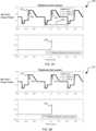
- FIG. 2Ashows the response 200 of the simple intra-period controller such as shown in FIG. 1A or FIG. 1B to a periodic input with period T p , 205.
- a host of different set pointse.g., a set point power of 1, followed by 2, followed by 5, with a ramp to 3 defines one period of the input.
- the output, 202follows the input, 201 with visible inaccuracy (where the output does not match the input set point).
- the time constant of the closed loop response for this illustrationis 10 ⁇ s.
- the output at a given point, A, 203can be obtained by multiplying the time shifted time reversed impulse response of the system with the input and integrating.
- the normalized time shifted time reversed impulse response of the unit, 204shows that the output at point A, 203, is heavily influenced by the very recent past (within one time constant or 10 ⁇ s prior to point A), and almost not at all by events occurring earlier than 10 time constants prior to point A.
- the conventional controllermust be very fast. As shown in FIG. 2B (prior art), speeding up the controller improves the ability of the output to follow the input accurately.
- the time constant of the closed loop response for this illustrationis 5 ⁇ s.
- the response, 250shows that the output, 252, follows the input, 251, more closely.
- the normalized time shifted time reversed impulse response 254shows that the point A, 253, is now even more heavily influenced by the input in the very recent past.
- the error controlis based on the measured value of the current output (within the period) against the set point. So, referring to Fig. 2A , for example, the measured value of the output at time 1.5 ms would be compared against the set point value at that same time to generate the error signal. Stated differently, the set point values are compared against the measured values during the current period to generate the error signal for the conventional intra-period controller.
- an inter-period controllercompares the measured value of the output one or more cycles in the past for a given set point and uses the past measured value at the set point to generate the current error signal and controller output. Referring again to Fig.
- the measured value at time 0.94 ms(which is one waveform repetition period of 0.56 ms earlier or that part of the preceding pulse that correlates with time 1.5 ms) with the same set point of 3 would be used by the controller to generate the error and output, as opposed to the measured value within the pulse at time 1.5 ms.
- the inter-period controllerneed not be nearly as fast because it relies on a measured value one cycle in the past as opposed to an immediately proximate value within the pulse.
- the pulse(e.g., the pulse over period Tp) is divided into multiple time periods, and the corresponding (same) output value in the same time period of the previous pulse is used for the error signal.
- the time periodwould encompass the specific value of 0.56 ms within some range.
- the time periods by which pulses are dividedare such that any given time period does not encompass different set points, with the exception of sloped set point transitions.
- the inter-period pulse informationis stored in some form of memory such that it can be accessed and used by the controller for the error feedback of the succeeding pulse.
- Complicated pulsessuch as with sloped set point transitions, and otherwise different set points may benefit from relatively smaller time period subdivisions of the pulse, and therefore may require relatively larger and faster memory.
- pulses with between a 100 ms and 10 ⁇ s period Tpmay be subdivided into 1024 time slices, and output values for each slice stored for comparison to the measured values in the same time slice of the subsequent pulse.
- no error signalis generated.
- information about an impedance presented to a generatorone or multiple periods, T p , 205, in the past can be used to adjust variable impedance elements within the matching network at the present time. The information can be used to calculate adjustments to the variable impedance matching elements without first generating an error signal.
- the setpointe.g. 101, 151, 303, 351, 501
- the setpointis generally constant, but there is a periodic disturbance of the load impedance that must be matched to a desired input impedance.
- Such a periodic disturbancecan for example arise from delivering power to a plasma load that follows a prescribed pattern of output versus time where the pattern repeats with a repetition period.
- a synchronization signal from for example the power source providing the prescribed pattern of powercan be provided to the matching network to assist the matching network in synchronizing with the repetitive waveform of the disturbance.
- FIG. 3Aillustrates a block diagram of one example of an inter-period controller 300 that may be implemented in a plasma power delivery system according to one embodiment of the present disclosure.
- FIG. 3Billustrates a block diagram of an alternate example implementation of an inter-period controller 350 that may be implemented in a plasma power delivery system according to another embodiment of the present disclosure.
- Some implementations of the inter-period controllers described hereinmay be considered multi-input-multi-output (MIMO) controllers.
- MIMOmulti-input-multi-output
- the controllers or more generally control elementsmay be implemented in hardware and software, with various possibly combinations of the same.
- the control elementmay be integrated with the generator or other device, or may be a separate component.
- the inter-period controllermay reside in a different piece of equipment from what is being controlled.
- a controller connected to an impedance matching networkmay reside in the generator but control variable impedance elements in the impedance matching network.
- forward and reflected signals from a couplermay be obtained from a coupler residing in the generator, filtered in analog, digitized in an analog to digital converter, and processed to extract the impedance presented to the generator by the match network by a microprocessor running a software program or by digital logic circuits implemented in, for example, an FPGA.
- the measurementscan be stored in memory by a microprocessor or reconfigurable digital circuits residing in an FPGA.
- the memory containing samples of impedance measurements at different timescan be processed using software running in a microprocessor or by an FPGA.
- the software or FPGAcan use samples one or multiple waveform repetition periods in the past to implement an inter-period control scheme.
- information about past values of variable impedance elements in the matchcan also be used.
- the controllercan then send control signals to the match to change variable impedance elements in the match.
- FIG. 3Aimplements the inter-period controller (providing an interleaved scheme) as a number, N, of controllers each running at the repetition period, T p , of the input.
- the block 301shows the first such controller and the block 302 shows the N-th such controller.
- the input, 303is sampled and digitized by an analog to digital converter, 304, at a sampling rate of 1/T s .
- the inputmay already exist as a data stream in which case the converter 304 is not used.
- the sampled inputis switched or routed to the controllers in turn by a switch, 305 so that each controller receives an updated input at a rate of 1/T p .
- the outputs of the controllersare routed to a common control input, c, by a switch 306.
- the control inputis converted to analog by a digital to analog converter 307 and applied to the control input of a plant, P, 308.
- the output, y, 309,is sampled by each controller at a rate of 1/T p by a sampler (313 for controller 301).
- Each controllercreates an error function (310 for controller 301) by subtracting the input from the sampled output. (Since the sampled output is delayed by a waveform period, T p , this implements an inter-period controller.) The error function is integrated (by 311 for controller 301) producing an output (312 for controller 301).
- extra controllersmay be utilized. For example, there may be N+3 controllers to deal with a T p that can vary three sampling periods.
- FIG. 3Bshows an alternate implementation of an inter-period controller 350 in accordance with an embodiment of the present disclosure.
- the input 351is sampled and digitized by an analog to digital converter, 352, at a sampling rate of 1/T s .
- the inputmay already exist as a data stream in which case the converter 352 is not used.
- the output 358is sampled and digitized by an analog to digital converter 359.
- the outputmay be a digital data stream derived from a measurement of the output in which case the analog to digital converter may not be implemented as shown.
- An error function 353is obtained by subtracting the input from the output.
- the controller 354generates the control input to the plant, c, 355, from the values of the control input to the plant, c, 355, and the error function, e, 353, one period of the input, T p ago. This is significantly different from a conventional intra-period controller as will be shown infra.
- the control input to the plantis converted to an analog signal by a digital to analog converter, 356, and applied to a plant, 357.
- FIGS. 4A - 4Dshow the response of an inter-period controller that may be implemented in a plasma power delivery system according to one embodiment of the present disclosure to a periodic control input.
- FIGs. 4A and 4Bthe response 400 of the output 402 to a periodic input 401 is shown.
- the outputslowly converges to the input ( FIG. 4A ), but after about 30 cycles of the input ( FIG. 4B ) the output 404 follows the input 403 with almost imperceptible error.
- FIG. 4Cshows that a point A, 451, on the response 450 and the points that influence point A. Note that for the inter-period controller point A, 451, is still significantly influenced by the input 5 ms in the past.
- FIG. 5illustrates a block diagram of an example combined inter-period and intra-period controller 500 that may be implemented in a plasma power delivery system according to one embodiment of the present disclosure.
- the input, 501is sampled and digitized by an analog to digital converter, 502, at a sampling rate of 1/T s .
- the inputmay already exist as a data stream in which case the converter 502 is not used.
- the output 509is sampled and digitized by an analog to digital converter 510.
- the outputmay be a digital data stream derived from a measurement of the output in which case the analog to digital converter may not be implemented as shown.
- An error function 503is obtained by subtracting the input from the output.
- the control input, c, 506,is a weighted average of a value based on values one sampling period, T s , ago and one period of the input, T p , ago. This weighting is perhaps more clearly illustrated in the sequence (sampled time) domain shown in equation 505.
- the control input to the plant, c, 506,is converted to an analog signal by a digital to analog converter, 507, and applied to a plant, 508.
- Nis allowed to vary based on the number of sampling periods, T s , that fit in the previous period of the input, T p .
- This example combined inter-period and intra-period controller 500has the additional advantage that it can easily transition from operating with a periodic input to operating with a non-repetitive input, 501.
- the Bode plot of the loop gain of an inter-period controlleris shown in FIG. 6A .
- the loop gainis very different from a traditional intra-period controller.
- FIG. 6Bshows a Nyquist plot of the loop gain.
- the magnitude of the loop gainis scaled by log 2 (1 + log 2 (1 + •)). This mapping maps 0 to 0, 1 to 1 and is monotonically increasing so we can still verify that the point -1 + j0 in the complex plane is not encircled.
- FIG. 6Cshows the magnitude and phase of the closed loop response of the system.
- FIG. 6Dshows the magnitude and phase of the closed loop response of the system only at the harmonics of the input and +/-1 Hz from the harmonics of the input.
- FIG. 6Dshows that the gain at the harmonics is unity gain confirming that a periodic input with period T p will be followed with precision.
- the points that have exactly 0 dB gain and 0 phase (unity gain)are exactly at the harmonics of the input, points having a gain of -0.04 dB and phase of +/-5 degrees are 1 Hz above and below the harmonic of the input.
- the Bode plot of the loop gain of the combined inter-period and intra-period controlleris shown in FIG. 7A .
- the loop gainis very different from a traditional intra-period controller.
- the magnitude of the gainreturns to high but finite values at the harmonics of the input (multiples of 1/T p ); a unique property of the combined inter-period and intra-period controller.
- FIG. 7Bshows a Nyquist plot of the loop gain. To facilitate interpretation of the Nyquist plot, the magnitude of the loop gain is scaled by log 2 (1 + log 2 (1 + •)).
- FIG. 7Cshows the magnitude and phase of the closed loop response of the system.
- FIG. 7Dshows the magnitude and phase of the closed loop response of the system only at the harmonics of the input and +/-1 Hz from the harmonics of the input.
- FIG. 7Dshows that the gain at the first few harmonics of the input is close to unity gain showing that the first few harmonic components of the input will be followed with good precision.
- the Bode plot of the loop gain of the combined inter-period and intra-period controlleris shown in FIG. 8A .
- the loop gainapproaches that of a traditional intra-period controller.
- FIG. 8Bshows a Nyquist plot of the loop gain.
- the magnitude of the loop gainis scaled by log 2 (1 + log 2 (1 + •)). This mapping maps 0 to 0, 1 to 1 and is monotonic increasing so we can still verify that the point -1 + j0 in the complex plane is not encircled.
- the Nyquist plotshows that the system is stable.
- FIG. 8Cshows the magnitude and phase of the closed loop response of the system.
- FIG. 7Dshows the magnitude and phase of the closed loop response of the system only at the harmonics of the input and +/-1 Hz from the harmonics of the input.
- FIG. 7Dshows that the gain at the first few harmonics of the input is close to unity gain showing that the first few harmonic components of the input will be followed with good precision.
- This controllerapproaches the performance of an intra-period controller with a gain cross over frequency of 10 kHz.
- FIG. 9illustrates a block diagram of a multi-input multi-output version of an example combined inter-period and intra-period controller 900 that may be implemented in a plasma power delivery system according to one embodiment of the present disclosure.
- the input, 901is sampled and digitized by analog to digital converters, 902, at a sampling rate of 1/T s .
- the inputmay already exist as a data stream in which case the converters 902 are not used.
- the inputis multi-dimensional and may, for example, contain inputs for output power and generator source impedance.
- the output 907is sampled and digitized by analog to digital converters 909.
- the outputmay be a digital data stream derived from a measurement of the output in which case the analog to digital converters may not be implemented as shown).
- the outputis multi-dimensional and may, for example, include measurements of output power and impedance presented to the generator.
- the dimensionality of the input 901 and output 907do not have to agree. This is so because an element of the output may contain a measure of something that is being minimized or maximized and thus does not require an input (e.g., the mismatch of the load impedance presented to the generator to a desired load impedance). Also, an element of the input may not require a corresponding measurement if the value can simply be set and does not require a corresponding measurement (e.g., setting the generator source impedance).
- Measurements of the input 901, control input 904, perturbation 908, and output 907are stored in a memory 910.
- the controllercan also generate a perturbation 908 that is added to the calculated control.
- the control input 904 to the plant added to the perturbation 908is converted to an analog signals by digital to analog converters, 905, and applied to a plant, 906.
- Perturbations 908can be used to extract correlations between the control input 904 and output 907. For example perturbing the control element in 904 that primarily controls output power (e.g. drive level to a power amplifier) and observing the change in both output power and impedance presented to the generator by the plasma load and then perturbing the control element that primarily controls the impedance presented to the generator (e.g.
- correlationcan be extracted between different time periods.
- the controllercan determine how a change in an element of the control input in one time period affects the output in successive time periods.
- Output resistanceis only one component of load impedance. In a practical application it is load impedance that is important, not just the resistive part of load impedance. In such a case a third input would have to be utilized (e.g. a variable reactance element in a matching network), or optimization techniques can be employed to find the best solution using only two inputs controlling three outputs rather than the simple computations in the example.
- Multi-input multi-output control in conjunction with inter-period controlallows control of multiple parameters in one control loop. This avoids the problem of interfering control loops which normally necessitates using widely differing speeds for different control loops in the same plasma power delivery system.
- Inter-period controlallows for a single controller to more readily control multiple generators delivering power to the same plasma system.
- the data rate for inter-period and intra-period controllersare the same since the control input to the plant is updated at the sampling rate 1/T s .
- the intra-period controllerneeds information from one sampling period T s earlier to update a current control input to a plant whereas the inter-period controller needs information from one input period T p earlier to update a control input to a plant. Since in most cases T p is multiple times longer than T s , it is much easier to get information to and from a controller before that information is needed for the inter-period controller.
- Inter-period controllerscan thus much more readily take interactions between different generators into account to improve overall control of all generators delivering power to the same plasma system.
- the controllersused samples of signals one sampling period, T s , or one repetition period, T p , in the past.
- T ssampling period
- T prepetition period
- the controllercan also use samples of signals multiple sampling periods or repetition periods in the past.
Landscapes
- Physics & Mathematics (AREA)
- Engineering & Computer Science (AREA)
- Plasma & Fusion (AREA)
- Chemical & Material Sciences (AREA)
- Analytical Chemistry (AREA)
- Plasma Technology (AREA)
- Drying Of Semiconductors (AREA)
- Inverter Devices (AREA)
- Golf Clubs (AREA)
Description
- This application is related to and claims priority from
U.S. Patent Application No. 62/529,963, filed July 7, 2017 - Aspects of the present disclosure relate to improved methods and systems for controlling a power delivery system, and particularly for controlling a plasma power delivery system.
US2013/002136 A1 is a document that describes a power delivery system configured to monitor characteristics of a generator, a match network, and a plasma load, via one or more sensors, and control these components via a local controller in order to improve power delivery accuracy and consistency to the plasma load.US2009/0237170 A1 discloses an RF power generator whose frequency is fine-tuned by an inter-pulse controller, whereby a system is obtained with similar performance to a true intra-pulse control system, but which is implemented using a lower speed and stable controller. - Plasma processing systems are used to deposit thin films on a substrate using processes such as chemical vapor deposition (CVD) and physical vapor deposition (PVD) as well to remove films from the substrate using etch processes. The plasma is often created by coupling radio frequency (RF) or direct current (DC) generators to a plasma chamber filled with gases injected into the plasma chamber at low pressure. Typically, a generator delivers RF power to an antenna in the plasma chamber, and power delivered at the antenna ignites and sustains a plasma. In some instances, the RF generator is coupled to an impedance matching network that may match the plasma impedance to a desired impedance, typically 50 Ω, at the generator output. DC power is typically coupled to chamber via one or more electrodes. The generator alone or the generator in combination with other pieces of equipment, such as the impedance matching network, other generators coupled to the same plasma, cables, etc., constitute a plasma power delivery system.
- Modulation of the power delivered to the plasma system is often required. Most modulation schemes are repetitive, i.e., the same modulation waveform is repeated at a waveform repetition rate. The associated waveform repetition period is equal to one divided by the waveform repetition rate. The ability to follow a prescribed modulation waveform using a traditional control scheme requires high bandwidth from the controller and ultimately from the measurement system. Many plasma systems have power applied to the plasma at different frequencies. The nonlinear nature of the plasma load creates intermodulation products that can interfere with a generator's measurements system. Thus, it is sometimes advantageous to use a narrowband measurement system to limit such interference. In many applications, power delivered to the plasma load is not the only parameter that is being controlled. For example, in RF power delivery systems, the impedance presented to the generator by the plasma load can be controlled, either through controlling the frequency of the generator output or through controlling a variable impedance match network between the generator and the plasma load. In some cases, generator source impedance may also be controlled. Tracking and controlling power in light of these various issues presents ever greater control challenges.
- It is with these observations in mind, among others, that aspects of the present disclosure were conceived.
- The invention is defined by the claims. According to one embodiment, a generator produces output, such as delivered power, voltage, current, forward power etc. that follows a prescribed pattern of output versus time where the pattern repeats with a repetition period, by controlling sections of the pattern based on measurements taken one or more repetition periods in the past. In one example, a power delivery system involves a generator that produces a repeating output pattern and a control element controls the repeating pattern based on a measurement of a value of the repeating pattern taken a period prior to a current period. The control element may further control the repeating output pattern based on the measurement of the repeating pattern taken a period prior to the current period combined with a measurement of a value of the repeating pattern during a current period. The repeating output pattern may follow a prescribed pattern of output versus time wherein the prescribed pattern repeats with a repetition period, and wherein the measurement of the value of the repeating pattern taken a period prior to the current period occurs one or more repetition periods in the past.
- According to yet another example not covered by the claims, a variable impedance match network controls the impedance presented to a RF generator while the generator produces output, such as delivered power, voltage, current, forward power, etc., that follows a prescribed pattern of output versus time where the pattern repeats with a repetition period by controlling variable impedance elements in the match network during sections of the pattern based on measurements taken one or more repetition periods in the past. The generator may provide the delivered power, voltage, current, forward power, etc., to a plasma system in order to ignite and sustain a plasma, in various possible embodiments.
- According to yet another embodiment, a generator produces output that follows a prescribed pattern of output versus time where the pattern repeats with a repetition period by controlling sections of the pattern based on measurements taken one or more repetition periods in the past; and combining this controller with an intra-period controller that calculates the control output based on measurements taken less than a repetition period in the past.
- According to yet another example not covered by the claims, a variable impedance match network controls the impedance presented to a RF generator while the generator produces output, such as delivered power, voltage, current, forward power, etc., that follows a prescribed pattern of output versus time where the pattern repeats with a repetition period by controlling variable impedance elements in the match network during sections of the pattern based on measurements taken one or more repetition periods in the past; and combining this controller with an intra-period controller that calculates the control of the variable impedance elements in the match network based on measurements taken less than a repetition period in the past.
- According to another embodiment, a generator produces output that follows a prescribed pattern of output versus time where the pattern repeats with a repetition period by controlling sections of the pattern based on measurements taken one or more repetition periods in the past while at the same time adjusting another parameter such as generator output frequency or variable impedance elements contained in the generator or in a variable impedance matching network coupled between the generator and the plasma based on measurements taken one or more repetition periods in the past where the correlation between the control inputs such as power control and generator frequency and control outputs such as delivered power and impedance presented to the generator is determined and used by the control system.
- According to yet another embodiment, a generator produces output that follows a prescribed pattern of output versus time where the pattern repeats with a repetition period by controlling a section of the pattern based on measurements taken for the same section one or more repetition periods in the past; as well as such measurements for other sections in the pattern by perturbing the control input, determining the response to the perturbation, and using the response to the perturbation to compensate for coupling between adjacent or closely located time periods in the waveform.
- The various features and advantages of the technology of the present disclosure will be apparent from the following description of particular embodiments of those technologies, as illustrated in the accompanying drawings. It should be noted that the drawings are not necessarily to scale; however the emphasis instead is being placed on illustrating the principles of the technological concepts. Also, in the drawings the like reference characters may refer to the same parts throughout the different views. The drawings depict only typical embodiments of the present disclosure and, therefore, are not to be considered limiting in scope.
FIG. 1A illustrates a simple analog intra-period, andFIG. 1B illustrates a simple digital intra-period control systems that may be used to control a plasma power delivery system.FIG. 2A illustrates the response of a relatively slow intra-period control system to a periodic input andFIG. 2B illustrates the response of a relatively fast intra-period control system to a periodic input.FIG. 3A and FIG. 3B illustrate block diagrams of example inter-period controllers that may be implemented in a plasma power delivery system according to embodiments of the present disclosure.FIG. 4A - FIG. 4D illustrate the response of an example inter-period controller to a periodic input.FIG. 5 illustrates a block diagram of an example combined inter-period and intra-period controller that may be implemented in a plasma power delivery system according to one embodiment of the present disclosure.FIG. 6A illustrates the loop gain as a function of frequency of an example pure inter-period controller.FIG. 6B illustrates the Nyquist plot of the loop gain for the inter-period controller generating the loop gain ofFig. 6A .FIG. 6C illustrates the closed loop response as a function of frequency for the inter-period controller generating the loop gain ofFig. 6A .FIG. 6D illustrates the closed loop response as a function of frequency at and close to the harmonics of the input waveform for the pure inter-period controller.FIG. 7A illustrates the loop gain as a function of frequency of an example combined inter-period and intra-period controller with a 0.1 weighting for the inter-period part and a 0.9 weighting for the intra-period part.FIG. 7B illustrates the Nyquist plot of the loop gain related toFig. 7A .FIG. 7C illustrates the closed loop response as a function of frequency of the example combined controller related toFig. 7A .FIG. 7D illustrates the closed loop response as a function of frequency at and close to the harmonics of the input waveform for the combined inter-period and intra-period controller related toFig. 7A .FIG. 8A illustrates the loop gain as a function of frequency of an example combined inter-period and intra-period controller with a 0.01 weighting for the inter-period part and a 0.99 weighting for the intra-period part.FIG. 8B illustrates the Nyquist plot of the loop gain for the combined controller related toFig. 8A .FIG. 8C illustrates the closed loop response as a function of frequency for the combined controller related toFig. 8A .FIG. 8D illustrates the closed loop response as a function of frequency at and close to the harmonics of the input waveform for the same combined inter-period and intra-period controller related toFig. 8A .FIG. 9 illustrates a block diagram of a multi-input multi-output version of a combined inter-period and intra-period controller according to one embodiment of the present disclosure.- Embodiments of the present disclosure provide a plasma power delivery system that produces an output, such as delivered power, voltage, current, and forward power, that follows a prescribed pattern of output versus time where the pattern repeats with a repetition period by controlling sections of the pattern based on measurements taken one or more repetition periods in the past as opposed to within the current period. Compared to a conventional controller, such an inter-period controller can reproduce output more accurately utilizing a lower bandwidth measurement and control system. The benefits provided by the inter-period controller can be advantageous in various contexts including in the presence of plasma generated mixing and intermodulation products. In additional embodiments, the inter-period controller can be combined with a conventional intra-period controller. In additional embodiments, parameters, such as generator output frequency, may be adjusted together with the main output based on measurements taken one or more repetition periods in the past where the correlation between the control inputs, such as power control and generator frequency, and control outputs, such as delivered power and impedance presented to the generator are determined and used by the control system. In additional embodiments, a generator produces output that follows a prescribed pattern of output versus time where the pattern repeats with a repetition period by controlling a section of the pattern based on measurements taken for the same section one or more repetition periods in the past; as well as such measurements for other sections in the pattern by perturbing the control input, determining the response to the perturbation, and using the response to the perturbation to compensate for coupling between adjacent or closely located time periods in the waveform.
- While primarily described with reference to a controller for a generator, aspects of the present disclosure are applicable to switch mode power supplies, and controllers for the same, which may be used in eV source applications such as to provide a bias to a substrate as part of an overall power delivery system, as well as other substrate biasing schemes. The controller and control schemes discussed herein may also be used to control variable impedance elements (such as vacuum variable capacitors or switched variable reactance elements) of impedance matching networks. In such instances, aspects of the present disclosure may or may not also be used in the controlling of an RF supply to the impedance matching network as part of the overall power delivery system. The controller may reside in any part of the power delivery system (e.g., in the generator or in the matching network) and may or may not receive information from and control other parts of the power delivery system. For example, a controller residing in the generator may control both a generator and a match that are part of the power delivery system with information obtained only from the generator, only from the match or from both the generator and the match. The controller and control schemes discussed herein may also be used in other systems with or without delivering power in a plasma power delivery environment.
FIG. 1A (prior art) illustrates a simple analog intra-period, andFIG. 1B (prior art) illustrates a simple digital intra-period control systems that may be used to control a plasma power delivery system. InFIG. 1A the difference between aninput 101 andoutput 106 produces anerror signal 102 that acontroller 103 uses to produce acontrol input 104 to aplant 105. In this illustration, the controller is a simple integrator with a gain of k. In an actual implementation, thecontrol input 104, c, may be a drive level to a power amplifier, and theplant 105, P, a power amplifier. To illustrate the performance differences between this controller and the disclosed inter-period controller, theplant 105, P, is a unity gain block, i.e.y =c. With these assumptions, the loop gain has unity gain at k rad/s or k/(2π) Hz, the time constant of the system step response is 1/k s and the integral of the impulse response of the system reaches 63.2% (1 - 1/e) in 1/k s. InFIG. 1B , aninput 151 is sampled at a sampling rate of 1/Ts and digitized by asampler 157. (In some applications the input is already a digital data stream and thesampler 157 is not present in the system.) Theoutput 156 is sampled and digitized by asampler 159 and the difference between the input and output produces anerror signal 152 that acontroller 153 uses to produce acontrol input 154 which is converted to an analog control signal by a digital toanalog converter 158 which is fed to aplant 155. As forFIG. 1A , to illustrate the performance differences between this controller and the disclosed inter-period controller, theplant 105, P, is a unity gain block. The same statements regarding relationship between k and the unity gain frequency and response times hold as for the analog controller ofFIG. 1A provided that k is much less than 2π/Ts.FIG. 2A (prior art) shows theresponse 200 of the simple intra-period controller such as shown inFIG. 1A or FIG. 1B to a periodic input with period Tp, 205. In this example a host of different set points (e.g., a set point power of 1, followed by 2, followed by 5, with a ramp to 3) defines one period of the input. The output, 202, follows the input, 201 with visible inaccuracy (where the output does not match the input set point). The time constant of the closed loop response for this illustration is 10 µs. The output at a given point, A, 203, can be obtained by multiplying the time shifted time reversed impulse response of the system with the input and integrating. The normalized time shifted time reversed impulse response of the unit, 204, shows that the output at point A, 203, is heavily influenced by the very recent past (within one time constant or 10 µs prior to point A), and almost not at all by events occurring earlier than 10 time constants prior to point A. To accommodate the changing set points within a pulse, the conventional controller must be very fast. As shown inFIG. 2B (prior art), speeding up the controller improves the ability of the output to follow the input accurately. The time constant of the closed loop response for this illustration is 5 µs. The response, 250, shows that the output, 252, follows the input, 251, more closely. The normalized time shifted time reversedimpulse response 254 shows that the point A, 253, is now even more heavily influenced by the input in the very recent past.- In these conventional intra-period controllers, the error control is based on the measured value of the current output (within the period) against the set point. So, referring to
Fig. 2A , for example, the measured value of the output at time 1.5 ms would be compared against the set point value at that same time to generate the error signal. Stated differently, the set point values are compared against the measured values during the current period to generate the error signal for the conventional intra-period controller. In contrast, an inter-period controller compares the measured value of the output one or more cycles in the past for a given set point and uses the past measured value at the set point to generate the current error signal and controller output. Referring again toFig. 2A , for example, at time 1.5 ms with a set point of 3, the measured value at time 0.94 ms (which is one waveform repetition period of 0.56 ms earlier or that part of the preceding pulse that correlates with time 1.5 ms) with the same set point of 3 would be used by the controller to generate the error and output, as opposed to the measured value within the pulse at time 1.5 ms. Notably, the inter-period controller need not be nearly as fast because it relies on a measured value one cycle in the past as opposed to an immediately proximate value within the pulse. - In some examples, the pulse (e.g., the pulse over period Tp) is divided into multiple time periods, and the corresponding (same) output value in the same time period of the previous pulse is used for the error signal. Referring again to the example immediately above referring to using the measured value at time 0.94 ms of the first pulse for the error correction at time 1.5 ms of the following second pulse, the time period would encompass the specific value of 0.56 ms within some range. In one example, the time periods by which pulses are divided are such that any given time period does not encompass different set points, with the exception of sloped set point transitions.
- In various implementations, the inter-period pulse information is stored in some form of memory such that it can be accessed and used by the controller for the error feedback of the succeeding pulse. Complicated pulses, such as with sloped set point transitions, and otherwise different set points may benefit from relatively smaller time period subdivisions of the pulse, and therefore may require relatively larger and faster memory. In specific examples, pulses with between a 100 ms and 10µs period Tp may be subdivided into 1024 time slices, and output values for each slice stored for comparison to the measured values in the same time slice of the subsequent pulse.
- In some applications no error signal is generated. In impedance matching applications using an inter-period control scheme information about an impedance presented to a generator one or multiple periods, Tp, 205, in the past can be used to adjust variable impedance elements within the matching network at the present time. The information can be used to calculate adjustments to the variable impedance matching elements without first generating an error signal. In impedance matching applications the setpoint (e.g. 101, 151, 303, 351, 501) is generally constant, but there is a periodic disturbance of the load impedance that must be matched to a desired input impedance. Such a periodic disturbance can for example arise from delivering power to a plasma load that follows a prescribed pattern of output versus time where the pattern repeats with a repetition period. In such a case a synchronization signal from for example the power source providing the prescribed pattern of power can be provided to the matching network to assist the matching network in synchronizing with the repetitive waveform of the disturbance.
FIG. 3A illustrates a block diagram of one example of aninter-period controller 300 that may be implemented in a plasma power delivery system according to one embodiment of the present disclosure.FIG. 3B illustrates a block diagram of an alternate example implementation of aninter-period controller 350 that may be implemented in a plasma power delivery system according to another embodiment of the present disclosure. Some implementations of the inter-period controllers described herein may be considered multi-input-multi-output (MIMO) controllers. The controllers or more generally control elements may be implemented in hardware and software, with various possibly combinations of the same. The control element may be integrated with the generator or other device, or may be a separate component. In some applications the inter-period controller may reside in a different piece of equipment from what is being controlled. As an example, a controller connected to an impedance matching network may reside in the generator but control variable impedance elements in the impedance matching network. In such an application forward and reflected signals from a coupler may be obtained from a coupler residing in the generator, filtered in analog, digitized in an analog to digital converter, and processed to extract the impedance presented to the generator by the match network by a microprocessor running a software program or by digital logic circuits implemented in, for example, an FPGA. The measurements can be stored in memory by a microprocessor or reconfigurable digital circuits residing in an FPGA. The memory containing samples of impedance measurements at different times can be processed using software running in a microprocessor or by an FPGA. The software or FPGA can use samples one or multiple waveform repetition periods in the past to implement an inter-period control scheme. To implement such a scheme information about past values of variable impedance elements in the match can also be used. The controller can then send control signals to the match to change variable impedance elements in the match.FIG. 3A implements the inter-period controller (providing an interleaved scheme) as a number, N, of controllers each running at the repetition period, Tp, of the input. Theblock 301 shows the first such controller and theblock 302 shows the N-th such controller. The input, 303, is sampled and digitized by an analog to digital converter, 304, at a sampling rate of 1/Ts. (The input may already exist as a data stream in which case theconverter 304 is not used.) The sampled input is switched or routed to the controllers in turn by a switch, 305 so that each controller receives an updated input at a rate of 1/Tp. The outputs of the controllers are routed to a common control input, c, by aswitch 306. The control input is converted to analog by a digital toanalog converter 307 and applied to the control input of a plant, P, 308. The output, y, 309, is sampled by each controller at a rate of 1/Tp by a sampler (313 for controller 301).- Each controller creates an error function (310 for controller 301) by subtracting the input from the sampled output. (Since the sampled output is delayed by a waveform period, Tp, this implements an inter-period controller.) The error function is integrated (by 311 for controller 301) producing an output (312 for controller 301). The number of controllers, N, and the sampling period Ts is adjusted so that NTs = Tp. To cater for situations where the repetition period of the input, Tp, may vary a few sampling periods, extra controllers may be utilized. For example, there may be N+3 controllers to deal with a Tp that can vary three sampling periods. When an extra control section is not updated due to a shorter than maximum Tp, the state of the last updated controller can be copied to the extra control section.
FIG. 3B shows an alternate implementation of aninter-period controller 350 in accordance with an embodiment of the present disclosure. Theinput 351 is sampled and digitized by an analog to digital converter, 352, at a sampling rate of 1/Ts. (The input may already exist as a data stream in which case theconverter 352 is not used.) Theoutput 358 is sampled and digitized by an analog todigital converter 359. (The output may be a digital data stream derived from a measurement of the output in which case the analog to digital converter may not be implemented as shown.) Anerror function 353 is obtained by subtracting the input from the output. Thecontroller 354 generates the control input to the plant, c, 355, from the values of the control input to the plant, c, 355, and the error function, e, 353, one period of the input, Tp ago. This is significantly different from a conventional intra-period controller as will be shown infra. The control input to the plant is converted to an analog signal by a digital to analog converter, 356, and applied to a plant, 357. As for thecontroller 300, provision can be made to deal with situations where the repetition period of the input, Tp, may vary a few sampling periods. In this case, N is allowed to vary based on the number of sampling periods Ts that fit in the previous period of the input Tp.FIGS. 4A - 4D show the response of an inter-period controller that may be implemented in a plasma power delivery system according to one embodiment of the present disclosure to a periodic control input. InFIGs. 4A and 4B theresponse 400 of theoutput 402 to aperiodic input 401 is shown. As shown in theresponse 400, the output slowly converges to the input (FIG. 4A ), but after about 30 cycles of the input (FIG. 4B ) theoutput 404 follows theinput 403 with almost imperceptible error.FIG. 4C shows that a point A, 451, on theresponse 450 and the points that influence point A. Note that for the inter-period controller point A, 451, is still significantly influenced by theinput 5 ms in the past. Thus, even though each section of the output approaches the input with a time constant on the order of 5 ms, after a few periods of the input, the output can follow the input with almost imperceptible error. For the conventional intra-period controller, even with a 5 µs time constant, the output does not follow the input with this precision.FIG. 5 illustrates a block diagram of an example combined inter-period andintra-period controller 500 that may be implemented in a plasma power delivery system according to one embodiment of the present disclosure. The input, 501, is sampled and digitized by an analog to digital converter, 502, at a sampling rate of 1/Ts. (The input may already exist as a data stream in which case theconverter 502 is not used.) Theoutput 509 is sampled and digitized by an analog todigital converter 510. (The output may be a digital data stream derived from a measurement of the output in which case the analog to digital converter may not be implemented as shown.) Anerror function 503 is obtained by subtracting the input from the output. Thecontroller 504 generates the control input to the plant, c, 506, from the values of the control input to the plant, c, 506, and the error function, e, 503, one period of the input, Tp, ago and one sampling period, Ts, ago. N and Ts are chosen to satisfy Tp=NTs. The control input, c, 506, is a weighted average of a value based on values one sampling period, Ts, ago and one period of the input, Tp, ago. This weighting is perhaps more clearly illustrated in the sequence (sampled time) domain shown inequation 505. In 504 and 505, We is a real number between 0 and 1 and Wa = 1 - We. If We = 1, the controller is a pure inter-period controller and if We=0 the controller is a conventional intra-period controller. The control input to the plant, c, 506, is converted to an analog signal by a digital to analog converter, 507, and applied to a plant, 508.- Provision can be made to deal with situations where the repetition period of the input, Tp, may vary a few sampling periods. In this case, N is allowed to vary based on the number of sampling periods, Ts, that fit in the previous period of the input, Tp. In this case, if a section towards the end of the repetition was not recently updated, rather than copying the state from a prior sample, the weighting can be changed to run a pure intra-period controller (We = 0) until the start of the next period of the input. This example combined inter-period and
intra-period controller 500 has the additional advantage that it can easily transition from operating with a periodic input to operating with a non-repetitive input, 501. FIG. 6A, FIG 6B, FIG. 6C and FIG. 6D illustrate properties of an example inter-period controller such as 300, 350 or 500 (with We=1) that may be implemented in a plasma power delivery system according to one embodiment of the present disclosure. For ease of illustration, inFIG. 6 the plant, P, 308, 357 or 506 is a simple unity gain block, the sample period Ts = 1 µs, the repetition period Tp = 1 ms, and hence N = Tp/Ts = 1000, and k (ke in 500) = 62.83. The Bode plot of the loop gain of an inter-period controller is shown inFIG. 6A . The loop gain is very different from a traditional intra-period controller. There is a first gain cross over frequency at 10 Hz as may be expected for a gain, k (ke in 500) = 62.83 = 2π10, but the magnitude of the gain returns to infinity at the harmonics of the input (multiples of 1/Tp); a unique property of the inter-period controller that allows it to follow a periodic input with unprecedented precision.FIG. 6B shows a Nyquist plot of the loop gain. To facilitate interpretation of the Nyquist plot, the magnitude of the loop gain is scaled by log2(1 + log2(1 + •)). This mapping maps 0 to 0, 1 to 1 and is monotonically increasing so we can still verify that the point -1 + j0 in the complex plane is not encircled. Despite the multiple gain crossings in the Bode plot, the Nyquist plot shows that the system is stable.FIG. 6C shows the magnitude and phase of the closed loop response of the system.FIG. 6D shows the magnitude and phase of the closed loop response of the system only at the harmonics of the input and +/-1 Hz from the harmonics of the input.FIG. 6D shows that the gain at the harmonics is unity gain confirming that a periodic input with period Tp will be followed with precision. InFIG. 6D the points that have exactly 0 dB gain and 0 phase (unity gain) are exactly at the harmonics of the input, points having a gain of -0.04 dB and phase of +/-5 degrees are 1 Hz above and below the harmonic of the input.FIG. 7A, FIG 7B, FIG. 7C and FIG. 7D illustrate properties of an example combined inter-period controller andintra-period controller 500 with We=0.1 that may be implemented in a plasma power delivery system according to one embodiment of the present disclosure. For ease of illustration, inFIG. 7 the plant, P, 506 is a simple unity gain block, the sample period Ts = 1 µs, the repetition period Tp = 1 ms, and hence N = Tp/Ts = 1000, ke = 62.83, and ka = 62830. The Bode plot of the loop gain of the combined inter-period and intra-period controller is shown inFIG. 7A . The loop gain is very different from a traditional intra-period controller. There is a first gain cross over frequency at 100 Hz, which is between the cross over frequency for We=1 of 10 Hz, and the cross over for We=0 of 10 kHz. The magnitude of the gain returns to high but finite values at the harmonics of the input (multiples of 1/Tp); a unique property of the combined inter-period and intra-period controller.FIG. 7B shows a Nyquist plot of the loop gain. To facilitate interpretation of the Nyquist plot, the magnitude of the loop gain is scaled by log2(1 + log2(1 + •)). This mapping maps 0 to 0, 1 to 1 and is monotonic increasing so we can still verify that the point -1 + j0 in the complex plane is not encircled. Despite the multiple gain crossings in the Bode plot, the Nyquist plot shows that the system is stable.FIG. 7C shows the magnitude and phase of the closed loop response of the system.FIG. 7D shows the magnitude and phase of the closed loop response of the system only at the harmonics of the input and +/-1 Hz from the harmonics of the input.FIG. 7D shows that the gain at the first few harmonics of the input is close to unity gain showing that the first few harmonic components of the input will be followed with good precision.FIG. 8A, FIG 8B, FIG. 8C and FIG. 8D illustrate properties of an example combined inter-period controller andintra-period controller 500 with We=0.01 that may be implemented in a plasma power delivery system according to one embodiment of the present disclosure. InFIG. 8 the plant, P, 506 is a simple unity gain block, the sample period Ts = 1 µs, the repetition period Tp = 1 ms, and hence N = Tp/Ts = 1000, ke = 62.83, and ka = 62830. The Bode plot of the loop gain of the combined inter-period and intra-period controller is shown inFIG. 8A . The loop gain approaches that of a traditional intra-period controller. There is a first gain cross over frequency at 9.1 kHz, which is between the cross over frequency for We=1 of 10 Hz, and the cross over for We=0 of 10 kHz. The magnitude of the gain returns to values higher than unity two more times as the frequency increases.FIG. 8B shows a Nyquist plot of the loop gain. To facilitate interpretation of the Nyquist plot, the magnitude of the loop gain is scaled by log2(1 + log2(1 + •)). This mapping maps 0 to 0, 1 to 1 and is monotonic increasing so we can still verify that the point -1 + j0 in the complex plane is not encircled. Despite the multiple gain crossings in the Bode plot, the Nyquist plot shows that the system is stable.FIG. 8C shows the magnitude and phase of the closed loop response of the system.FIG. 7D shows the magnitude and phase of the closed loop response of the system only at the harmonics of the input and +/-1 Hz from the harmonics of the input.FIG. 7D shows that the gain at the first few harmonics of the input is close to unity gain showing that the first few harmonic components of the input will be followed with good precision. This controller approaches the performance of an intra-period controller with a gain cross over frequency of 10 kHz.FIG. 9 illustrates a block diagram of a multi-input multi-output version of an example combined inter-period andintra-period controller 900 that may be implemented in a plasma power delivery system according to one embodiment of the present disclosure. The input, 901, is sampled and digitized by analog to digital converters, 902, at a sampling rate of 1/Ts. (The input may already exist as a data stream in which case theconverters 902 are not used.) The input is multi-dimensional and may, for example, contain inputs for output power and generator source impedance. Theoutput 907 is sampled and digitized by analog todigital converters 909. (The output may be a digital data stream derived from a measurement of the output in which case the analog to digital converters may not be implemented as shown). The output is multi-dimensional and may, for example, include measurements of output power and impedance presented to the generator. The dimensionality of theinput 901 andoutput 907 do not have to agree. This is so because an element of the output may contain a measure of something that is being minimized or maximized and thus does not require an input (e.g., the mismatch of the load impedance presented to the generator to a desired load impedance). Also, an element of the input may not require a corresponding measurement if the value can simply be set and does not require a corresponding measurement (e.g., setting the generator source impedance). Measurements of theinput 901, controlinput 904,perturbation 908, andoutput 907 are stored in amemory 910. Thecontroller 903 generates the control input to the plant, c, 904, from the values stored in memory, one period of the input, Tp, ago and one sampling period, Ts ago. N and Ts are chosen to satisfy Tp=NTs.- In addition to calculating values of the control input to the plant, 904, the controller can also generate a
perturbation 908 that is added to the calculated control. Thecontrol input 904 to the plant added to theperturbation 908 is converted to an analog signals by digital to analog converters, 905, and applied to a plant, 906.Perturbations 908 can be used to extract correlations between thecontrol input 904 andoutput 907. For example perturbing the control element in 904 that primarily controls output power (e.g. drive level to a power amplifier) and observing the change in both output power and impedance presented to the generator by the plasma load and then perturbing the control element that primarily controls the impedance presented to the generator (e.g. generator frequency) and observing both output power and impedance presented to the generator by the plasma load allows the controller to extract the correlation betweencontrol inputs 904 and outputs 907. If the input is periodically modulated, the correlation betweencontrol inputs 904 andoutputs 907 are also modulated (assuming the load is nonlinear as is the case for most plasma loads). An inter-period controller can correlatecontrol inputs 904 andoutputs 907 for each specific time period in the repetitive input cycle. For example, for Tp= 1 ms and Ts=1 µs, the controller can maintain 1000 matrices correlating 904 with 907 for each of the 1000 time periods in the input. In addition to extracting correlation between elements of thecontrol input 904 and elements of theoutput 907 for each specific time period, correlation can be extracted between different time periods. For example, the controller can determine how a change in an element of the control input in one time period affects the output in successive time periods. - A simple example illustrates the advantage of knowing these correlations. Consider the decision on how to update a two-dimensional control vector (e.g. drive and frequency) and a two dimensional output (e.g. output power and load resistance) for the 7th time period in the periodic input. Let the desired change in the outputs of the 7th time period be:


- Multi-input multi-output control in conjunction with inter-period control allows control of multiple parameters in one control loop. This avoids the problem of interfering control loops which normally necessitates using widely differing speeds for different control loops in the same plasma power delivery system.
- Inter-period control allows for a single controller to more readily control multiple generators delivering power to the same plasma system. The data rate for inter-period and intra-period controllers are the same since the control input to the plant is updated at the
sampling rate 1/Ts. However, the intra-period controller needs information from one sampling period Ts earlier to update a current control input to a plant whereas the inter-period controller needs information from one input period Tp earlier to update a control input to a plant. Since in most cases Tp is multiple times longer than Ts, it is much easier to get information to and from a controller before that information is needed for the inter-period controller. Inter-period controllers can thus much more readily take interactions between different generators into account to improve overall control of all generators delivering power to the same plasma system. - In the given examples of inter-period and mixed inter-period and intra-period controllers, the controllers used samples of signals one sampling period, Ts, or one repetition period, Tp, in the past. Of course the controller can also use samples of signals multiple sampling periods or repetition periods in the past.


Claims (13)
- A generator comprising:a power amplifier (906) configured to produce a power signal comprising a periodic repeating pattern of values comprising multi-dimensional output values (907), the pattern of values produced over a period of time comprising a repetition period of the power signal; anda control element (903) configured to control the power amplifier to produce the periodic repeating pattern based on:a multi-dimensional input (901);a measurement of a value of the periodic repeating pattern taken a repetition period of the power signal prior to a current period of the power signal;and a plurality of correlations between elements of multi-dimensional control input values (904) and elements of the multi-dimensional output values (907).
- The generator of Claim 1 wherein in use the control element (903) is configured to control the periodic repeating pattern based on the measurement of the periodic repeating pattern taken a repetition period of the power signal prior to the current repetition period of the power signal combined with a measurement of a value of the periodic repeating pattern during a current repetition period of the power signal.
- The generator of Claim 1 wherein in use the periodic repeating pattern follows a prescribed pattern of output versus time wherein the prescribed pattern repeats with a repetition period, and wherein the measurement of the value of the periodic repeating pattern taken a repetition period prior to the current repetition period occurs one or more repetition periods in the past.
- The generator of any of Claims 1-3 configured such that a correlation between the elements of the multi-dimensional control input values for a specific time period in the periodic repeating pattern and the elements of the multi-dimensional output values for the same specific time period is determined and used by the control element (903).
- The generator of Claim 4 configured such that the correlation between the elements of the multi-dimensional control input values (904) and the elements of the multi-dimensional output values (907) is determined by perturbing the control input values and observing a response to the perturbation.
- The generator of Claim 4 configured such that the correlation between the elements of the multi-dimensional control input values (904) for a specific time period in the periodic repeating pattern and time periods adjacent to the specific time period and the elements of the multi-dimensional output values (907) for the specific time period is determined and used by the control element (903).
- The generator of Claim 6 configured such that the correlation between the elements of the multi-dimensional control input values (904) and the elements of the multi-dimensional output values (907) is determined by perturbing the control input values (904) and observing the response to the perturbation.
- The generator of Claim 4 where one element of the periodic repeating pattern is one of voltage, current and power or combinations thereof and another element of the periodic repeating pattern is one of impedance presented to the generator and source impedance of the generator.
- A power delivery method comprising:producing a power signal with a control system, wherein the power signal comprises a periodic repeating pattern of values comprising multi-dimensional output values (907), wherein the power signal follows a prescribed pattern over a period of time comprising a repetition period of the power signal, and wherein the control system comprises a control element (903); controlling the repetitions of the prescribed pattern based on a multi-dimensional input (901);based on a measurement of a value of the prescribed pattern taken from one or more repetition periods of the power signal prior to a current period of the power signal; and based on a plurality of correlations between elements of multi-dimensional control input values (904) and elements of the multi-dimensional output values (907) stored in a memory.
- The method of Claim 9 comprising the step of combining a measurement taken from one or more previous repetition periods with a measurement taken from a current repetition period.
- A plasma power delivery system comprising:an impedance matching network configured to match a load impedance to a desired impedance in which the load impedance is subject to a periodic modulation pattern of values that repeats with a repetition period; anda control element (903) operably associated with the impedance matching network, the control element configured to control, based on a measurement of a value of the load impedance taken one or more repetition periods of the periodic modulation pattern in the past and a plurality of correlations between elements of multi-dimensional control input values and elements of multi-dimensional output values, a variable impedance element in the impedance matching network.
- The plasma power delivery system of Claim 11 wherein the control element (903) is configured to control the variable impedance element in the impedance matching network based on the measurement of the value of the load impedance taken one or more repetition periods of the periodic modulation pattern in the past combined with a measurement of a value of the load impedance taken less than a repetition period of the periodic modulation pattern in the past.
- The plasma power delivery system of any of Claims 11-12, wherein the plurality of correlations between the elements of the multi-dimensional control values (904) and the elements of the multi-dimensional output values (907) is stored as a correlation matrix.
Applications Claiming Priority (2)
| Application Number | Priority Date | Filing Date | Title |
|---|---|---|---|
| US201762529963P | 2017-07-07 | 2017-07-07 | |
| PCT/US2018/040930WO2019010312A1 (en) | 2017-07-07 | 2018-07-05 | Inter-period control system for plasma power delivery system and method of operating the same |
Publications (3)
| Publication Number | Publication Date |
|---|---|
| EP3616235A1 EP3616235A1 (en) | 2020-03-04 |
| EP3616235A4 EP3616235A4 (en) | 2021-02-24 |
| EP3616235B1true EP3616235B1 (en) | 2024-10-09 |
Family
ID=64903415
Family Applications (1)
| Application Number | Title | Priority Date | Filing Date |
|---|---|---|---|
| EP18827671.1AActiveEP3616235B1 (en) | 2017-07-07 | 2018-07-05 | Inter-period control system for plasma power delivery system and method of operating the same |
Country Status (7)
| Country | Link |
|---|---|
| US (4) | US10861677B2 (en) |
| EP (1) | EP3616235B1 (en) |
| JP (3) | JP6971376B2 (en) |
| KR (2) | KR102504624B1 (en) |
| CN (2) | CN115662868A (en) |
| TW (3) | TWI811658B (en) |
| WO (2) | WO2019010312A1 (en) |
Families Citing this family (17)
| Publication number | Priority date | Publication date | Assignee | Title |
|---|---|---|---|---|
| CN109148250B (en)* | 2017-06-15 | 2020-07-17 | 北京北方华创微电子装备有限公司 | Impedance matching device and impedance matching method |
| KR102504624B1 (en)* | 2017-07-07 | 2023-02-27 | 어드밴스드 에너지 인더스트리즈 인코포레이티드 | Inter-period control system for plasma power delivery system and method of operating the same |
| US11615943B2 (en)* | 2017-07-07 | 2023-03-28 | Advanced Energy Industries, Inc. | Inter-period control for passive power distribution of multiple electrode inductive plasma source |
| US11651939B2 (en)* | 2017-07-07 | 2023-05-16 | Advanced Energy Industries, Inc. | Inter-period control system for plasma power delivery system and method of operating same |
| KR20210149225A (en) | 2019-04-29 | 2021-12-08 | 램 리써치 코포레이션 | Systems and methods for multi-level pulsing of RF plasma tools |
| US11315757B2 (en) | 2019-08-13 | 2022-04-26 | Mks Instruments, Inc. | Method and apparatus to enhance sheath formation, evolution and pulse to pulse stability in RF powered plasma applications |
| US10741363B1 (en)* | 2019-10-08 | 2020-08-11 | Mks Instruments, Inc. | Extremum seeking control apparatus and method for automatic frequency tuning for RF impedance matching |
| JP7511501B2 (en)* | 2021-02-10 | 2024-07-05 | 東京エレクトロン株式会社 | Plasma processing apparatus and monitoring device |
| WO2022211915A1 (en)* | 2021-04-01 | 2022-10-06 | Advanced Energy Industries, Inc. | Inter-period control system for plasma power delivery system and method of operating the same |
| US11476090B1 (en)* | 2021-08-24 | 2022-10-18 | Applied Materials, Inc. | Voltage pulse time-domain multiplexing |
| US12300464B2 (en)* | 2021-10-25 | 2025-05-13 | Advanced Energy Industries, Inc. | Robust tensorized shaped setpoint waveform streaming control |
| KR20230129089A (en) | 2022-02-28 | 2023-09-06 | 주식회사 엘지에너지솔루션 | Cylindrical secondary battery, and battery pack and vehicle including the same |
| DE102022108642A1 (en)* | 2022-04-08 | 2023-10-12 | TRUMPF Hüttinger GmbH + Co. KG | Plasma ignition detection device for connection to an impedance matching circuit for a plasma generation system |
| US12308803B2 (en)* | 2022-08-24 | 2025-05-20 | Shenzhen Jiangnan Industrial Co., Ltd. | Switching power supply frequency adaptive adjustment method, system and electronic device |
| US12278090B2 (en)* | 2023-04-18 | 2025-04-15 | Mks Instruments, Inc. | Enhanced tuning methods for mitigating RF load impedance variations due to periodic disturbances |
| US20250037972A1 (en)* | 2023-07-26 | 2025-01-30 | Advanced Energy Industries, Inc. | Match network design for use with frequency sweeping |
| US20250087462A1 (en)* | 2023-09-08 | 2025-03-13 | Applied Materials, Inc. | Radio-frequency (rf) matching network and tuning technique |
Family Cites Families (87)
| Publication number | Priority date | Publication date | Assignee | Title |
|---|---|---|---|---|
| JPS61245202A (en)* | 1985-04-23 | 1986-10-31 | Isao Takahashi | Non-interference shortest time control method |
| US5187454A (en)* | 1992-01-23 | 1993-02-16 | Applied Materials, Inc. | Electronically tuned matching network using predictor-corrector control system |
| ES2206454T3 (en) | 1992-03-12 | 2004-05-16 | Ipm International Sa | METHOD AND DEVICE THAT ALLOWS THE REDUCTION OF POWER CONSUMPTION IN A PUBLIC TELEPHONE. |
| US5325019A (en)* | 1992-08-21 | 1994-06-28 | Sematech, Inc. | Control of plasma process by use of harmonic frequency components of voltage and current |
| KR20010031093A (en)* | 1997-10-14 | 2001-04-16 | 로버트 엠. 포터 | System for plasma ignition by fast voltage rise |
| JP2002184598A (en)* | 2000-12-12 | 2002-06-28 | Shimadzu Corp | High frequency power supply for ICP |
| US6459067B1 (en)* | 2001-04-06 | 2002-10-01 | Eni Technology, Inc. | Pulsing intelligent RF modulation controller |
| JP3778842B2 (en) | 2001-10-30 | 2006-05-24 | パール工業株式会社 | High frequency detection method and high frequency detection circuit |
| US20040016402A1 (en) | 2002-07-26 | 2004-01-29 | Walther Steven R. | Methods and apparatus for monitoring plasma parameters in plasma doping systems |
| US7115185B1 (en)* | 2003-09-16 | 2006-10-03 | Advanced Energy Industries, Inc. | Pulsed excitation of inductively coupled plasma sources |
| US7169256B2 (en) | 2004-05-28 | 2007-01-30 | Lam Research Corporation | Plasma processor with electrode responsive to multiple RF frequencies |
| TWI574318B (en) | 2004-06-21 | 2017-03-11 | Tokyo Electron Ltd | A plasma processing apparatus, a plasma processing method, and a computer-readable recording medium |
| US7988816B2 (en) | 2004-06-21 | 2011-08-02 | Tokyo Electron Limited | Plasma processing apparatus and method |
| JP4739793B2 (en) | 2005-03-31 | 2011-08-03 | 株式会社ダイヘン | High frequency power supply |
| US7173495B1 (en) | 2005-04-05 | 2007-02-06 | Pericom Semiconductor Corp | Redundant back-up PLL oscillator phase-locked to primary oscillator with fail-over to back-up oscillator without a third oscillator |
| US7602127B2 (en) | 2005-04-18 | 2009-10-13 | Mks Instruments, Inc. | Phase and frequency control of a radio frequency generator from an external source |
| US7477711B2 (en)* | 2005-05-19 | 2009-01-13 | Mks Instruments, Inc. | Synchronous undersampling for high-frequency voltage and current measurements |
| US20080179948A1 (en)* | 2005-10-31 | 2008-07-31 | Mks Instruments, Inc. | Radio frequency power delivery system |
| KR20080072642A (en) | 2005-10-31 | 2008-08-06 | 엠케이에스 인스트루먼츠, 인코포레이티드 | High frequency power delivery system |
| US9011633B2 (en)* | 2005-11-17 | 2015-04-21 | Mks Instruments, Inc. | Broadband techniques to reduce the effects of impedance mismatch in plasma chambers |
| US8932430B2 (en) | 2011-05-06 | 2015-01-13 | Axcelis Technologies, Inc. | RF coupled plasma abatement system comprising an integrated power oscillator |
| US7777567B2 (en)* | 2007-01-25 | 2010-08-17 | Mks Instruments, Inc. | RF power amplifier stability network |
| EP2097920B1 (en)* | 2007-07-23 | 2017-08-09 | TRUMPF Hüttinger GmbH + Co. KG | Plasma supply device |
| US9039871B2 (en)* | 2007-11-16 | 2015-05-26 | Advanced Energy Industries, Inc. | Methods and apparatus for applying periodic voltage using direct current |
| US7839223B2 (en)* | 2008-03-23 | 2010-11-23 | Advanced Energy Industries, Inc. | Method and apparatus for advanced frequency tuning |
| US8847561B2 (en) | 2008-05-07 | 2014-09-30 | Advanced Energy Industries, Inc. | Apparatus, system, and method for controlling a matching network based on information characterizing a cable |
| US7872523B2 (en)* | 2008-07-01 | 2011-01-18 | Mks Instruments, Inc. | Radio frequency (RF) envelope pulsing using phase switching of switch-mode power amplifiers |
| TWI511622B (en)* | 2008-07-07 | 2015-12-01 | Lam Res Corp | Passive capacitively-coupled electrostatic(cce) probe arrangement for detecting in-situ arcing events in a plasma processing chamber |
| US9997325B2 (en)* | 2008-07-17 | 2018-06-12 | Verity Instruments, Inc. | Electron beam exciter for use in chemical analysis in processing systems |
| US8044594B2 (en)* | 2008-07-31 | 2011-10-25 | Advanced Energy Industries, Inc. | Power supply ignition system and method |
| US7894927B2 (en)* | 2008-08-06 | 2011-02-22 | Tokyo Electron Limited | Using Multi-Layer/Multi-Input/Multi-Output (MLMIMO) models for metal-gate structures |
| US9093853B2 (en)* | 2008-09-27 | 2015-07-28 | Witricity Corporation | Flexible resonator attachment |
| US8319436B2 (en)* | 2009-02-02 | 2012-11-27 | Advanced Energy Industries, Inc. | Passive power distribution for multiple electrode inductive plasma source |
| US8040068B2 (en) | 2009-02-05 | 2011-10-18 | Mks Instruments, Inc. | Radio frequency power control system |
| US8674606B2 (en)* | 2009-04-27 | 2014-03-18 | Advanced Energy Industries, Inc. | Detecting and preventing instabilities in plasma processes |
| US9287092B2 (en)* | 2009-05-01 | 2016-03-15 | Advanced Energy Industries, Inc. | Method and apparatus for controlling ion energy distribution |
| US8716984B2 (en) | 2009-06-29 | 2014-05-06 | Advanced Energy Industries, Inc. | Method and apparatus for modifying the sensitivity of an electrical generator to a nonlinear load |
| US8774743B2 (en)* | 2009-10-14 | 2014-07-08 | Blackberry Limited | Dynamic real-time calibration for antenna matching in a radio frequency receiver system |
| US8436643B2 (en)* | 2010-11-04 | 2013-05-07 | Advanced Energy Industries, Inc. | High frequency solid state switching for impedance matching |
| KR101675625B1 (en) | 2011-01-04 | 2016-11-22 | 어드밴스드 에너지 인더스트리즈 인코포레이티드 | System level power delivery to a plasma processing load |
| US8416008B2 (en)* | 2011-01-20 | 2013-04-09 | Advanced Energy Industries, Inc. | Impedance-matching network using BJT switches in variable-reactance circuits |
| US8501499B2 (en) | 2011-03-28 | 2013-08-06 | Tokyo Electron Limited | Adaptive recipe selector |
| JP5808012B2 (en)* | 2011-12-27 | 2015-11-10 | 東京エレクトロン株式会社 | Plasma processing equipment |
| US8576013B2 (en) | 2011-12-29 | 2013-11-05 | Mks Instruments, Inc. | Power distortion-based servo control systems for frequency tuning RF power sources |
| US8773019B2 (en)* | 2012-02-23 | 2014-07-08 | Mks Instruments, Inc. | Feedback control and coherency of multiple power supplies in radio frequency power delivery systems for pulsed mode schemes in thin film processing |
| US8952765B2 (en)* | 2012-03-23 | 2015-02-10 | Mks Instruments, Inc. | System and methods of bimodal automatic power and frequency tuning of RF generators |
| KR102133057B1 (en)* | 2012-06-22 | 2020-07-10 | 램 리써치 코포레이션 | Methods and apparatus for controlling plasma in a plasma processing system |
| US9214901B2 (en) | 2012-07-27 | 2015-12-15 | Mks Instruments, Inc. | Wideband AFT power amplifier systems with frequency-based output transformer impedance balancing |
| US9685297B2 (en)* | 2012-08-28 | 2017-06-20 | Advanced Energy Industries, Inc. | Systems and methods for monitoring faults, anomalies, and other characteristics of a switched mode ion energy distribution system |
| US9210790B2 (en)* | 2012-08-28 | 2015-12-08 | Advanced Energy Industries, Inc. | Systems and methods for calibrating a switched mode ion energy distribution system |
| US9316675B2 (en) | 2012-09-06 | 2016-04-19 | Mks Instruments, Inc. | Secondary plasma detection systems and methods |
| US8736377B2 (en)* | 2012-10-30 | 2014-05-27 | Mks Instruments, Inc. | RF pulse edge shaping |
| US9294100B2 (en)* | 2012-12-04 | 2016-03-22 | Advanced Energy Industries, Inc. | Frequency tuning system and method for finding a global optimum |
| US9014648B2 (en) | 2012-12-21 | 2015-04-21 | Qualcomm Incorporated | Diversity receiver with shared local oscillator signal in diversity mode |
| US8781415B1 (en) | 2013-02-07 | 2014-07-15 | Mks Instruments, Inc. | Distortion correction based feedforward control systems and methods for radio frequency power sources |
| US9536713B2 (en)* | 2013-02-27 | 2017-01-03 | Advanced Energy Industries, Inc. | Reliable plasma ignition and reignition |
| JP5787926B2 (en)* | 2013-03-29 | 2015-09-30 | 株式会社東芝 | Semiconductor switch circuit |
| US9620382B2 (en)* | 2013-12-06 | 2017-04-11 | University Of Maryland, College Park | Reactor for plasma-based atomic layer etching of materials |
| JP6413261B2 (en) | 2014-03-03 | 2018-10-31 | 株式会社島津製作所 | High frequency power supply for ICP emission analyzer |
| WO2015148490A1 (en)* | 2014-03-24 | 2015-10-01 | Advanced Energy Industries, Inc. | System and method for control of high efficiency generator source impedance |
| US9591739B2 (en) | 2014-05-02 | 2017-03-07 | Reno Technologies, Inc. | Multi-stage heterodyne control circuit |
| US9544987B2 (en)* | 2014-06-30 | 2017-01-10 | Advanced Energy Industries, Inc. | Frequency tuning for pulsed radio frequency plasma processing |
| KR102432150B1 (en)* | 2014-08-15 | 2022-08-11 | 어플라이드 머티어리얼스, 인코포레이티드 | Compact configurable modular radio frequency matching network assembly for plasma processing systems |
| US9854659B2 (en)* | 2014-10-16 | 2017-12-26 | Advanced Energy Industries, Inc. | Noise based frequency tuning and identification of plasma characteristics |
| US10049857B2 (en)* | 2014-12-04 | 2018-08-14 | Mks Instruments, Inc. | Adaptive periodic waveform controller |
| US9595424B2 (en)* | 2015-03-02 | 2017-03-14 | Lam Research Corporation | Impedance matching circuit for operation with a kilohertz RF generator and a megahertz RF generator to control plasma processes |
| US9596744B2 (en) | 2015-03-31 | 2017-03-14 | Lam Research Corporation | Radio frequency generator having multiple mutually exclusive oscillators for use in plasma processing |
| US9812305B2 (en)* | 2015-04-27 | 2017-11-07 | Advanced Energy Industries, Inc. | Rate enhanced pulsed DC sputtering system |
| US10566845B2 (en)* | 2015-06-30 | 2020-02-18 | Ossia Inc. | Techniques for clock synchronization and control in wireless power delivery environments |
| US9947514B2 (en) | 2015-09-01 | 2018-04-17 | Mks Instruments, Inc. | Plasma RF bias cancellation system |
| US9515633B1 (en)* | 2016-01-11 | 2016-12-06 | Lam Research Corporation | Transformer coupled capacitive tuning circuit with fast impedance switching for plasma etch chambers |
| US10431889B2 (en)* | 2016-04-22 | 2019-10-01 | The Charles Stark Draper Laboratory, Inc. | Low-loss compact transmit impedance matching tuning technique |
| US10187032B2 (en)* | 2016-06-17 | 2019-01-22 | Lam Research Corporation | Combiner and distributor for adjusting impedances or power across multiple plasma processing stations |
| US10269545B2 (en)* | 2016-08-03 | 2019-04-23 | Lam Research Corporation | Methods for monitoring plasma processing systems for advanced process and tool control |
| US10109460B2 (en)* | 2016-11-30 | 2018-10-23 | Lam Research Corporation | Universal non-invasive chamber impedance measurement system and associated methods |
| US10263577B2 (en)* | 2016-12-09 | 2019-04-16 | Advanced Energy Industries, Inc. | Gate drive circuit and method of operating the same |
| US11615943B2 (en)* | 2017-07-07 | 2023-03-28 | Advanced Energy Industries, Inc. | Inter-period control for passive power distribution of multiple electrode inductive plasma source |
| KR102504624B1 (en) | 2017-07-07 | 2023-02-27 | 어드밴스드 에너지 인더스트리즈 인코포레이티드 | Inter-period control system for plasma power delivery system and method of operating the same |
| US11651939B2 (en)* | 2017-07-07 | 2023-05-16 | Advanced Energy Industries, Inc. | Inter-period control system for plasma power delivery system and method of operating same |
| US10607813B2 (en)* | 2017-11-17 | 2020-03-31 | Advanced Energy Industries, Inc. | Synchronized pulsing of plasma processing source and substrate bias |
| JP2021503702A (en) | 2017-11-17 | 2021-02-12 | エーイーエス グローバル ホールディングス, プライベート リミテッド | Improved application of modulation sources in plasma processing systems |
| US10504744B1 (en)* | 2018-07-19 | 2019-12-10 | Lam Research Corporation | Three or more states for achieving high aspect ratio dielectric etch |
| US11183368B2 (en) | 2018-08-02 | 2021-11-23 | Lam Research Corporation | RF tuning systems including tuning circuits having impedances for setting and adjusting parameters of electrodes in electrostatic chucks |
| US11177115B2 (en)* | 2019-06-03 | 2021-11-16 | Applied Materials, Inc. | Dual-level pulse tuning |
| US11158488B2 (en)* | 2019-06-26 | 2021-10-26 | Mks Instruments, Inc. | High speed synchronization of plasma source/bias power delivery |
| US10741363B1 (en)* | 2019-10-08 | 2020-08-11 | Mks Instruments, Inc. | Extremum seeking control apparatus and method for automatic frequency tuning for RF impedance matching |
| US11232931B2 (en)* | 2019-10-21 | 2022-01-25 | Mks Instruments, Inc. | Intermodulation distortion mitigation using electronic variable capacitor |
- 2018
- 2018-07-05KRKR1020227004931Apatent/KR102504624B1/enactiveActive
- 2018-07-05EPEP18827671.1Apatent/EP3616235B1/enactiveActive
- 2018-07-05WOPCT/US2018/040930patent/WO2019010312A1/ennot_activeCeased
- 2018-07-05CNCN202211425596.0Apatent/CN115662868A/enactivePending
- 2018-07-05KRKR1020207001574Apatent/KR102364528B1/enactiveActive
- 2018-07-05CNCN201880045502.2Apatent/CN110870039B/enactiveActive
- 2018-07-05JPJP2020500181Apatent/JP6971376B2/enactiveActive
- 2018-07-05USUS16/028,131patent/US10861677B2/enactiveActive
- 2018-07-09TWTW110112724Apatent/TWI811658B/enactive
- 2018-07-09TWTW107123277Apatent/TWI727184B/enactive
- 2020
- 2020-12-06USUS17/113,088patent/US11450510B2/enactiveActive
- 2021
- 2021-05-28USUS17/333,764patent/US11610763B2/enactiveActive
- 2021-06-22JPJP2021103078Apatent/JP7153771B2/enactiveActive
- 2021-11-05JPJP2021180892Apatent/JP2022010078A/ennot_activeWithdrawn
- 2022
- 2022-05-16USUS18/576,193patent/US20240203689A1/enactivePending
- 2022-05-16WOPCT/US2022/029456patent/WO2022250997A1/ennot_activeCeased
- 2022-05-18TWTW111118532Apatent/TW202249400A/enunknown
Also Published As
| Publication number | Publication date |
|---|---|
| US20210118650A1 (en) | 2021-04-22 |
| CN110870039A (en) | 2020-03-06 |
| JP6971376B2 (en) | 2021-11-24 |
| TWI727184B (en) | 2021-05-11 |
| TW202249400A (en) | 2022-12-16 |
| US11450510B2 (en) | 2022-09-20 |
| KR20200018662A (en) | 2020-02-19 |
| US10861677B2 (en) | 2020-12-08 |
| US20210287880A1 (en) | 2021-09-16 |
| WO2022250997A9 (en) | 2023-10-26 |
| US20190013182A1 (en) | 2019-01-10 |
| US20240203689A1 (en) | 2024-06-20 |
| CN115662868A (en) | 2023-01-31 |
| EP3616235A4 (en) | 2021-02-24 |
| WO2019010312A1 (en) | 2019-01-10 |
| CN110870039B (en) | 2022-09-16 |
| EP3616235A1 (en) | 2020-03-04 |
| JP2021144953A (en) | 2021-09-24 |
| KR20220025919A (en) | 2022-03-03 |
| KR102364528B1 (en) | 2022-02-17 |
| JP2022010078A (en) | 2022-01-14 |
| WO2019010312A4 (en) | 2019-02-21 |
| TW201907762A (en) | 2019-02-16 |
| TW202131765A (en) | 2021-08-16 |
| KR102504624B1 (en) | 2023-02-27 |
| US11610763B2 (en) | 2023-03-21 |
| JP7153771B2 (en) | 2022-10-14 |
| JP2020526881A (en) | 2020-08-31 |
| TWI811658B (en) | 2023-08-11 |
| WO2022250997A1 (en) | 2022-12-01 |
Similar Documents
| Publication | Publication Date | Title |
|---|---|---|
| EP3616235B1 (en) | Inter-period control system for plasma power delivery system and method of operating the same | |
| US11615943B2 (en) | Inter-period control for passive power distribution of multiple electrode inductive plasma source | |
| CN111954916B (en) | Adaptive control for power generator | |
| US20210249228A1 (en) | Inter-period control system for plasma power delivery system and method of operating same | |
| CN108140530B (en) | Plasma RF bias cancellation system | |
| KR101787501B1 (en) | System and methods of bimodal automatic power and frequency tuning of rf generators | |
| KR102733972B1 (en) | Plasma processing apparatus and measurement circuit | |
| JPS628583A (en) | Apparatus for obtaining derivative of characteristic curve of electronic device and control of operation of electronic device | |
| WO2022211915A1 (en) | Inter-period control system for plasma power delivery system and method of operating the same | |
| WO2022173629A1 (en) | Inter-period control for passive power distribution of multiple electrode inductive plasma source | |
| Syed et al. | Identification of the Mechanical Dynamics of the Superconducting Radio-Frequency Cavities for the European XFEL CW Upgrade |
Legal Events
| Date | Code | Title | Description |
|---|---|---|---|
| STAA | Information on the status of an ep patent application or granted ep patent | Free format text:STATUS: THE INTERNATIONAL PUBLICATION HAS BEEN MADE | |
| PUAI | Public reference made under article 153(3) epc to a published international application that has entered the european phase | Free format text:ORIGINAL CODE: 0009012 | |
| STAA | Information on the status of an ep patent application or granted ep patent | Free format text:STATUS: REQUEST FOR EXAMINATION WAS MADE | |
| 17P | Request for examination filed | Effective date:20191127 | |
| AK | Designated contracting states | Kind code of ref document:A1 Designated state(s):AL AT BE BG CH CY CZ DE DK EE ES FI FR GB GR HR HU IE IS IT LI LT LU LV MC MK MT NL NO PL PT RO RS SE SI SK SM TR | |
| AX | Request for extension of the european patent | Extension state:BA ME | |
| DAV | Request for validation of the european patent (deleted) | ||
| DAX | Request for extension of the european patent (deleted) | ||
| A4 | Supplementary search report drawn up and despatched | Effective date:20210122 | |
| RIC1 | Information provided on ipc code assigned before grant | Ipc:H01J 37/32 20060101AFI20210118BHEP | |
| STAA | Information on the status of an ep patent application or granted ep patent | Free format text:STATUS: EXAMINATION IS IN PROGRESS | |
| 17Q | First examination report despatched | Effective date:20221006 | |
| P01 | Opt-out of the competence of the unified patent court (upc) registered | Effective date:20230908 | |
| GRAP | Despatch of communication of intention to grant a patent | Free format text:ORIGINAL CODE: EPIDOSNIGR1 | |
| STAA | Information on the status of an ep patent application or granted ep patent | Free format text:STATUS: GRANT OF PATENT IS INTENDED | |
| INTG | Intention to grant announced | Effective date:20240429 | |
| GRAS | Grant fee paid | Free format text:ORIGINAL CODE: EPIDOSNIGR3 | |
| GRAA | (expected) grant | Free format text:ORIGINAL CODE: 0009210 | |
| STAA | Information on the status of an ep patent application or granted ep patent | Free format text:STATUS: THE PATENT HAS BEEN GRANTED | |
| AK | Designated contracting states | Kind code of ref document:B1 Designated state(s):AL AT BE BG CH CY CZ DE DK EE ES FI FR GB GR HR HU IE IS IT LI LT LU LV MC MK MT NL NO PL PT RO RS SE SI SK SM TR | |
| REG | Reference to a national code | Ref country code:CH Ref legal event code:EP | |
| REG | Reference to a national code | Ref country code:DE Ref legal event code:R096 Ref document number:602018075297 Country of ref document:DE | |
| REG | Reference to a national code | Ref country code:IE Ref legal event code:FG4D | |
| REG | Reference to a national code | Ref country code:NL Ref legal event code:FP | |
| REG | Reference to a national code | Ref country code:LT Ref legal event code:MG9D | |
| REG | Reference to a national code | Ref country code:AT Ref legal event code:MK05 Ref document number:1731534 Country of ref document:AT Kind code of ref document:T Effective date:20241009 | |
| PG25 | Lapsed in a contracting state [announced via postgrant information from national office to epo] | Ref country code:PT Free format text:LAPSE BECAUSE OF FAILURE TO SUBMIT A TRANSLATION OF THE DESCRIPTION OR TO PAY THE FEE WITHIN THE PRESCRIBED TIME-LIMIT Effective date:20250210 Ref country code:IS Free format text:LAPSE BECAUSE OF FAILURE TO SUBMIT A TRANSLATION OF THE DESCRIPTION OR TO PAY THE FEE WITHIN THE PRESCRIBED TIME-LIMIT Effective date:20250209 Ref country code:HR Free format text:LAPSE BECAUSE OF FAILURE TO SUBMIT A TRANSLATION OF THE DESCRIPTION OR TO PAY THE FEE WITHIN THE PRESCRIBED TIME-LIMIT Effective date:20241009 | |
| PG25 | Lapsed in a contracting state [announced via postgrant information from national office to epo] | Ref country code:FI Free format text:LAPSE BECAUSE OF FAILURE TO SUBMIT A TRANSLATION OF THE DESCRIPTION OR TO PAY THE FEE WITHIN THE PRESCRIBED TIME-LIMIT Effective date:20241009 | |
| PG25 | Lapsed in a contracting state [announced via postgrant information from national office to epo] | Ref country code:BG Free format text:LAPSE BECAUSE OF FAILURE TO SUBMIT A TRANSLATION OF THE DESCRIPTION OR TO PAY THE FEE WITHIN THE PRESCRIBED TIME-LIMIT Effective date:20241009 | |
| PG25 | Lapsed in a contracting state [announced via postgrant information from national office to epo] | Ref country code:ES Free format text:LAPSE BECAUSE OF FAILURE TO SUBMIT A TRANSLATION OF THE DESCRIPTION OR TO PAY THE FEE WITHIN THE PRESCRIBED TIME-LIMIT Effective date:20241009 | |
| PG25 | Lapsed in a contracting state [announced via postgrant information from national office to epo] | Ref country code:NO Free format text:LAPSE BECAUSE OF FAILURE TO SUBMIT A TRANSLATION OF THE DESCRIPTION OR TO PAY THE FEE WITHIN THE PRESCRIBED TIME-LIMIT Effective date:20250109 | |
| PG25 | Lapsed in a contracting state [announced via postgrant information from national office to epo] | Ref country code:GR Free format text:LAPSE BECAUSE OF FAILURE TO SUBMIT A TRANSLATION OF THE DESCRIPTION OR TO PAY THE FEE WITHIN THE PRESCRIBED TIME-LIMIT Effective date:20250110 Ref country code:AT Free format text:LAPSE BECAUSE OF FAILURE TO SUBMIT A TRANSLATION OF THE DESCRIPTION OR TO PAY THE FEE WITHIN THE PRESCRIBED TIME-LIMIT Effective date:20241009 Ref country code:LV Free format text:LAPSE BECAUSE OF FAILURE TO SUBMIT A TRANSLATION OF THE DESCRIPTION OR TO PAY THE FEE WITHIN THE PRESCRIBED TIME-LIMIT Effective date:20241009 | |
| PG25 | Lapsed in a contracting state [announced via postgrant information from national office to epo] | Ref country code:PL Free format text:LAPSE BECAUSE OF FAILURE TO SUBMIT A TRANSLATION OF THE DESCRIPTION OR TO PAY THE FEE WITHIN THE PRESCRIBED TIME-LIMIT Effective date:20241009 | |
| PG25 | Lapsed in a contracting state [announced via postgrant information from national office to epo] | Ref country code:RS Free format text:LAPSE BECAUSE OF FAILURE TO SUBMIT A TRANSLATION OF THE DESCRIPTION OR TO PAY THE FEE WITHIN THE PRESCRIBED TIME-LIMIT Effective date:20250109 | |
| PG25 | Lapsed in a contracting state [announced via postgrant information from national office to epo] | Ref country code:SM Free format text:LAPSE BECAUSE OF FAILURE TO SUBMIT A TRANSLATION OF THE DESCRIPTION OR TO PAY THE FEE WITHIN THE PRESCRIBED TIME-LIMIT Effective date:20241009 | |
| PG25 | Lapsed in a contracting state [announced via postgrant information from national office to epo] | Ref country code:DK Free format text:LAPSE BECAUSE OF FAILURE TO SUBMIT A TRANSLATION OF THE DESCRIPTION OR TO PAY THE FEE WITHIN THE PRESCRIBED TIME-LIMIT Effective date:20241009 | |
| PGFP | Annual fee paid to national office [announced via postgrant information from national office to epo] | Ref country code:GB Payment date:20250529 Year of fee payment:8 | |
| REG | Reference to a national code | Ref country code:DE Ref legal event code:R097 Ref document number:602018075297 Country of ref document:DE | |
| PGFP | Annual fee paid to national office [announced via postgrant information from national office to epo] | Ref country code:NL Payment date:20250613 Year of fee payment:8 | |
| PG25 | Lapsed in a contracting state [announced via postgrant information from national office to epo] | Ref country code:EE Free format text:LAPSE BECAUSE OF FAILURE TO SUBMIT A TRANSLATION OF THE DESCRIPTION OR TO PAY THE FEE WITHIN THE PRESCRIBED TIME-LIMIT Effective date:20241009 | |
| PG25 | Lapsed in a contracting state [announced via postgrant information from national office to epo] | Ref country code:RO Free format text:LAPSE BECAUSE OF FAILURE TO SUBMIT A TRANSLATION OF THE DESCRIPTION OR TO PAY THE FEE WITHIN THE PRESCRIBED TIME-LIMIT Effective date:20241009 | |
| PG25 | Lapsed in a contracting state [announced via postgrant information from national office to epo] | Ref country code:SK Free format text:LAPSE BECAUSE OF FAILURE TO SUBMIT A TRANSLATION OF THE DESCRIPTION OR TO PAY THE FEE WITHIN THE PRESCRIBED TIME-LIMIT Effective date:20241009 | |
| PG25 | Lapsed in a contracting state [announced via postgrant information from national office to epo] | Ref country code:CZ Free format text:LAPSE BECAUSE OF FAILURE TO SUBMIT A TRANSLATION OF THE DESCRIPTION OR TO PAY THE FEE WITHIN THE PRESCRIBED TIME-LIMIT Effective date:20241009 | |
| PG25 | Lapsed in a contracting state [announced via postgrant information from national office to epo] | Ref country code:IT Free format text:LAPSE BECAUSE OF FAILURE TO SUBMIT A TRANSLATION OF THE DESCRIPTION OR TO PAY THE FEE WITHIN THE PRESCRIBED TIME-LIMIT Effective date:20241009 | |
| PLBE | No opposition filed within time limit | Free format text:ORIGINAL CODE: 0009261 | |
| STAA | Information on the status of an ep patent application or granted ep patent | Free format text:STATUS: NO OPPOSITION FILED WITHIN TIME LIMIT | |
| PG25 | Lapsed in a contracting state [announced via postgrant information from national office to epo] | Ref country code:SE Free format text:LAPSE BECAUSE OF FAILURE TO SUBMIT A TRANSLATION OF THE DESCRIPTION OR TO PAY THE FEE WITHIN THE PRESCRIBED TIME-LIMIT Effective date:20241009 | |
| 26N | No opposition filed | Effective date:20250710 |