EP3613598B1 - Symbol grouping and striping for wide field matrix laser marking - Google Patents
Symbol grouping and striping for wide field matrix laser markingDownload PDFInfo
- Publication number
- EP3613598B1 EP3613598B1EP19189510.1AEP19189510AEP3613598B1EP 3613598 B1EP3613598 B1EP 3613598B1EP 19189510 AEP19189510 AEP 19189510AEP 3613598 B1EP3613598 B1EP 3613598B1
- Authority
- EP
- European Patent Office
- Prior art keywords
- laser marking
- marking device
- code
- stripes
- Prior art date
- Legal status (The legal status is an assumption and is not a legal conclusion. Google has not performed a legal analysis and makes no representation as to the accuracy of the status listed.)
- Active
Links
Images


Classifications
- B—PERFORMING OPERATIONS; TRANSPORTING
- B41—PRINTING; LINING MACHINES; TYPEWRITERS; STAMPS
- B41M—PRINTING, DUPLICATING, MARKING, OR COPYING PROCESSES; COLOUR PRINTING
- B41M3/00—Printing processes to produce particular kinds of printed work, e.g. patterns
- B—PERFORMING OPERATIONS; TRANSPORTING
- B23—MACHINE TOOLS; METAL-WORKING NOT OTHERWISE PROVIDED FOR
- B23K—SOLDERING OR UNSOLDERING; WELDING; CLADDING OR PLATING BY SOLDERING OR WELDING; CUTTING BY APPLYING HEAT LOCALLY, e.g. FLAME CUTTING; WORKING BY LASER BEAM
- B23K26/00—Working by laser beam, e.g. welding, cutting or boring
- B23K26/08—Devices involving relative movement between laser beam and workpiece
- B23K26/083—Devices involving movement of the workpiece in at least one axial direction
- B23K26/0838—Devices involving movement of the workpiece in at least one axial direction by using an endless conveyor belt
- B—PERFORMING OPERATIONS; TRANSPORTING
- B23—MACHINE TOOLS; METAL-WORKING NOT OTHERWISE PROVIDED FOR
- B23K—SOLDERING OR UNSOLDERING; WELDING; CLADDING OR PLATING BY SOLDERING OR WELDING; CUTTING BY APPLYING HEAT LOCALLY, e.g. FLAME CUTTING; WORKING BY LASER BEAM
- B23K26/00—Working by laser beam, e.g. welding, cutting or boring
- B23K26/08—Devices involving relative movement between laser beam and workpiece
- B23K26/082—Scanning systems, i.e. devices involving movement of the laser beam relative to the laser head
- B—PERFORMING OPERATIONS; TRANSPORTING
- B23—MACHINE TOOLS; METAL-WORKING NOT OTHERWISE PROVIDED FOR
- B23K—SOLDERING OR UNSOLDERING; WELDING; CLADDING OR PLATING BY SOLDERING OR WELDING; CUTTING BY APPLYING HEAT LOCALLY, e.g. FLAME CUTTING; WORKING BY LASER BEAM
- B23K26/00—Working by laser beam, e.g. welding, cutting or boring
- B23K26/36—Removing material
- B23K26/362—Laser etching
- B—PERFORMING OPERATIONS; TRANSPORTING
- B41—PRINTING; LINING MACHINES; TYPEWRITERS; STAMPS
- B41J—TYPEWRITERS; SELECTIVE PRINTING MECHANISMS, i.e. MECHANISMS PRINTING OTHERWISE THAN FROM A FORME; CORRECTION OF TYPOGRAPHICAL ERRORS
- B41J11/00—Devices or arrangements of selective printing mechanisms, e.g. ink-jet printers or thermal printers, for supporting or handling copy material in sheet or web form
- B41J11/008—Controlling printhead for accurately positioning print image on printing material, e.g. with the intention to control the width of margins
- B—PERFORMING OPERATIONS; TRANSPORTING
- B41—PRINTING; LINING MACHINES; TYPEWRITERS; STAMPS
- B41J—TYPEWRITERS; SELECTIVE PRINTING MECHANISMS, i.e. MECHANISMS PRINTING OTHERWISE THAN FROM A FORME; CORRECTION OF TYPOGRAPHICAL ERRORS
- B41J11/00—Devices or arrangements of selective printing mechanisms, e.g. ink-jet printers or thermal printers, for supporting or handling copy material in sheet or web form
- B41J11/36—Blanking or long feeds; Feeding to a particular line, e.g. by rotation of platen or feed roller
- B41J11/42—Controlling printing material conveyance for accurate alignment of the printing material with the printhead; Print registering
- B41J11/425—Controlling printing material conveyance for accurate alignment of the printing material with the printhead; Print registering for a variable printing material feed amount
- B—PERFORMING OPERATIONS; TRANSPORTING
- B41—PRINTING; LINING MACHINES; TYPEWRITERS; STAMPS
- B41J—TYPEWRITERS; SELECTIVE PRINTING MECHANISMS, i.e. MECHANISMS PRINTING OTHERWISE THAN FROM A FORME; CORRECTION OF TYPOGRAPHICAL ERRORS
- B41J2/00—Typewriters or selective printing mechanisms characterised by the printing or marking process for which they are designed
- B41J2/435—Typewriters or selective printing mechanisms characterised by the printing or marking process for which they are designed characterised by selective application of radiation to a printing material or impression-transfer material
- B41J2/44—Typewriters or selective printing mechanisms characterised by the printing or marking process for which they are designed characterised by selective application of radiation to a printing material or impression-transfer material using single radiation source per colour, e.g. lighting beams or shutter arrangements
- B41J2/442—Typewriters or selective printing mechanisms characterised by the printing or marking process for which they are designed characterised by selective application of radiation to a printing material or impression-transfer material using single radiation source per colour, e.g. lighting beams or shutter arrangements using lasers
- B—PERFORMING OPERATIONS; TRANSPORTING
- B41—PRINTING; LINING MACHINES; TYPEWRITERS; STAMPS
- B41J—TYPEWRITERS; SELECTIVE PRINTING MECHANISMS, i.e. MECHANISMS PRINTING OTHERWISE THAN FROM A FORME; CORRECTION OF TYPOGRAPHICAL ERRORS
- B41J29/00—Details of, or accessories for, typewriters or selective printing mechanisms not otherwise provided for
- B41J29/38—Drives, motors, controls or automatic cut-off devices for the entire printing mechanism
- B41J29/393—Devices for controlling or analysing the entire machine ; Controlling or analysing mechanical parameters involving printing of test patterns
- B—PERFORMING OPERATIONS; TRANSPORTING
- B41—PRINTING; LINING MACHINES; TYPEWRITERS; STAMPS
- B41J—TYPEWRITERS; SELECTIVE PRINTING MECHANISMS, i.e. MECHANISMS PRINTING OTHERWISE THAN FROM A FORME; CORRECTION OF TYPOGRAPHICAL ERRORS
- B41J3/00—Typewriters or selective printing or marking mechanisms characterised by the purpose for which they are constructed
- B41J3/01—Typewriters or selective printing or marking mechanisms characterised by the purpose for which they are constructed for special character, e.g. for Chinese characters or barcodes
- B—PERFORMING OPERATIONS; TRANSPORTING
- B41—PRINTING; LINING MACHINES; TYPEWRITERS; STAMPS
- B41M—PRINTING, DUPLICATING, MARKING, OR COPYING PROCESSES; COLOUR PRINTING
- B41M5/00—Duplicating or marking methods; Sheet materials for use therein
- B41M5/26—Thermography ; Marking by high energetic means, e.g. laser otherwise than by burning, and characterised by the material used
- G—PHYSICS
- G06—COMPUTING OR CALCULATING; COUNTING
- G06F—ELECTRIC DIGITAL DATA PROCESSING
- G06F3/00—Input arrangements for transferring data to be processed into a form capable of being handled by the computer; Output arrangements for transferring data from processing unit to output unit, e.g. interface arrangements
- G06F3/12—Digital output to print unit, e.g. line printer, chain printer
- G06F3/1201—Dedicated interfaces to print systems
- G06F3/1202—Dedicated interfaces to print systems specifically adapted to achieve a particular effect
- G06F3/1211—Improving printing performance
- G06F3/1215—Improving printing performance achieving increased printing speed, i.e. reducing the time between printing start and printing end
- G—PHYSICS
- G06—COMPUTING OR CALCULATING; COUNTING
- G06F—ELECTRIC DIGITAL DATA PROCESSING
- G06F3/00—Input arrangements for transferring data to be processed into a form capable of being handled by the computer; Output arrangements for transferring data from processing unit to output unit, e.g. interface arrangements
- G06F3/12—Digital output to print unit, e.g. line printer, chain printer
- G06F3/1201—Dedicated interfaces to print systems
- G06F3/1223—Dedicated interfaces to print systems specifically adapted to use a particular technique
- G06F3/1237—Print job management
- G06F3/126—Job scheduling, e.g. queuing, determine appropriate device
- G06F3/1262—Job scheduling, e.g. queuing, determine appropriate device by grouping or ganging jobs
- G—PHYSICS
- G06—COMPUTING OR CALCULATING; COUNTING
- G06F—ELECTRIC DIGITAL DATA PROCESSING
- G06F3/00—Input arrangements for transferring data to be processed into a form capable of being handled by the computer; Output arrangements for transferring data from processing unit to output unit, e.g. interface arrangements
- G06F3/12—Digital output to print unit, e.g. line printer, chain printer
- G06F3/1201—Dedicated interfaces to print systems
- G06F3/1278—Dedicated interfaces to print systems specifically adapted to adopt a particular infrastructure
- G06F3/1282—High volume printer device
- B—PERFORMING OPERATIONS; TRANSPORTING
- B41—PRINTING; LINING MACHINES; TYPEWRITERS; STAMPS
- B41J—TYPEWRITERS; SELECTIVE PRINTING MECHANISMS, i.e. MECHANISMS PRINTING OTHERWISE THAN FROM A FORME; CORRECTION OF TYPOGRAPHICAL ERRORS
- B41J2/00—Typewriters or selective printing mechanisms characterised by the printing or marking process for which they are designed
- B41J2/435—Typewriters or selective printing mechanisms characterised by the printing or marking process for which they are designed characterised by selective application of radiation to a printing material or impression-transfer material
- G—PHYSICS
- G06—COMPUTING OR CALCULATING; COUNTING
- G06K—GRAPHICAL DATA READING; PRESENTATION OF DATA; RECORD CARRIERS; HANDLING RECORD CARRIERS
- G06K1/00—Methods or arrangements for marking the record carrier in digital fashion
- G06K1/12—Methods or arrangements for marking the record carrier in digital fashion otherwise than by punching
- G06K1/121—Methods or arrangements for marking the record carrier in digital fashion otherwise than by punching by printing code marks
- G—PHYSICS
- G06—COMPUTING OR CALCULATING; COUNTING
- G06K—GRAPHICAL DATA READING; PRESENTATION OF DATA; RECORD CARRIERS; HANDLING RECORD CARRIERS
- G06K1/00—Methods or arrangements for marking the record carrier in digital fashion
- G06K1/12—Methods or arrangements for marking the record carrier in digital fashion otherwise than by punching
- G06K1/126—Methods or arrangements for marking the record carrier in digital fashion otherwise than by punching by photographic or thermographic registration
- G—PHYSICS
- G06—COMPUTING OR CALCULATING; COUNTING
- G06K—GRAPHICAL DATA READING; PRESENTATION OF DATA; RECORD CARRIERS; HANDLING RECORD CARRIERS
- G06K15/00—Arrangements for producing a permanent visual presentation of the output data, e.g. computer output printers
- G06K15/02—Arrangements for producing a permanent visual presentation of the output data, e.g. computer output printers using printers
- G06K15/12—Arrangements for producing a permanent visual presentation of the output data, e.g. computer output printers using printers by photographic printing, e.g. by laser printers
Definitions
- This specificationrelates to industrial printing systems, and in particular, systems and techniques relating to laser printing product codes on the packaging of products in a manufacturing or distribution facility.
- U.S. Patent No. 7,046,267describes a laser printing system that organizes an image into a sequence of "stripes" for laser printing so as to provide an efficient print order of characters and symbols, which can improve printing by using more of the laser's exposure window (aperture) and reducing an amount of laser deflection motion between marking operations.
- US 7,167,194describes a printing method using a printing system that prints a code on a product moving in a direction. The code is constructed from a plurality of pixels in a first data set indicating the positions of the pixels and generates a corrected data set indicating the position that each pixel would occupy if each pixel was moved at the velocity of the product until the pixel was printed.
- US 6,061,081describes a scan-type laser marking device that includes a scanning speed setting device.
- US 4,636,043describes a laser beam scanning device that includes an optical system that is mounted on a carriage which is movable back and forth along a linear path in front of a target area and which is parallel to the optical path of a projected laser beam.
- This specificationdescribes technologies relating to industrial printing systems, and in particular, systems and techniques relating to laser printing product codes on the packaging of products in a manufacturing or distribution facility.
- the present inventionis directed to a method that includes: obtaining a code to be printed on one or more products by a laser marking device configured to direct a laser beam in two orthogonal directions to move between different locations and to dwell at the different locations to form marks on the one or more products; grouping discrete symbols in the code with each other into separate symbol groups based on locations of the discrete symbols in the code; organizing the separate symbol groups into one or more macro-level stripes in a direction perpendicular to a direction of motion of the one or more products in a product line configured to move products through a facility; organizing one or more symbols in each respective symbol group into one or more stripes in a direction perpendicular to a direction of motion of the one or more products in a product line configured to move products through a facility; adding an extra distance or a time delay between stripes in at least one of the separate symbol groups to prevent clipping of a symbol by the laser marking device due to a print aperture of the laser marking device; and causing the laser marking device to direct the laser beam in accordance with the separate symbol
- the methodcan include: assigning a group print priority to the separate symbol groups in accordance with a time at which each respective symbol group enters the print aperture of the laser marking device; and assigning, for each of the separate symbol groups having two or more stripes, a stripe print priority to the two or more stripes in accordance with a time at which each respective stripe enters the print aperture of the laser marking device; wherein causing the laser marking device to direct the laser beam in accordance with the separate symbol groups includes causing the laser marking device to direct the laser beam to print the separate symbol groups in an order of the group print priority and to print the two or more stripes within a symbol group in an order of the stripe print priority.
- the methodcan include: that assigning the group print priority includes treating each of the stripes of groups as a single group for priority assignment.
- the separate symbol groups organized into stripes of groupscan include at least four separate symbol groups.
- Obtaining the code to be printed on the one or more products by the laser marking devicecan include: receiving an image to be printed; receiving X and Y coordinates corresponding to the two orthogonal directions; and replicating the image in accordance with the X and Y coordinates to form the code to be printed.
- Grouping the discrete symbols in the codecan include grouping the discrete symbols in the code based on proximity of the discrete symbols to each other. Grouping the discrete symbols in the code can include: defining a containing boundary for each of the discrete symbols in the code; and grouping discrete symbols whose containing boundaries overlap each other.
- the containing boundary for each discrete symbolcan be set as a circle having a diameter equal to one and a half times a size of the symbol.
- the containing boundary for each discrete symbolcan be set in accordance with user input.
- a systemincludes: a product line configured to move products through a facility; a laser marking device arranged with respect to the product line and configured to direct a laser beam in two orthogonal directions to move between different locations and to dwell at the different locations to form marks on the products; and a laser marking device controller communicatively coupled with the laser marking device, the laser marking device controller being configured to obtain a code to be printed on the products, group discrete symbols in the code with each other into separate symbol groups based on locations of the discrete symbols in the code, organize the separate symbol groups into one or more macro-level stripes in a direction perpendicular to a direction of motion of the one or more products in a product line configured to move products through a facility; organize one or more symbols in each respective symbol group into one or more stripes in a direction perpendicular to a direction of motion of the products in the product line, add an extra distance or a time
- the laser marking device controllercan be configured to assign a group print priority to the separate symbol groups in accordance with a time at which each respective symbol group enters the print aperture of the laser marking device, assign, for each of the separate symbol groups having two or more stripes, a stripe print priority to the two or more stripes in accordance with a time at which each respective stripe enters the print aperture of the laser marking device, and cause the laser marking device to direct the laser beam to print the separate symbol groups in an order of the group print priority and to print the two or more stripes within a symbol group in an order of the stripe print priority.
- the laser marking device controllercan be configured to treat each of the stripes of groups as a single group for priority assignment.
- the separate symbol groups organized into stripes of groupscan include at least four separate symbol groups.
- the laser marking device controllercan be configured to obtain the code to be printed on the one or more products by the laser marking device by receiving an image to be printed, receive X and Y coordinates corresponding to the two orthogonal directions, and replicate the image in accordance with the X and Y coordinates to form the code to be printed.
- the laser marking device controllercan be configured to group the discrete symbols in the code based on proximity of the discrete symbols to each other.
- the laser marking device controllercan be configured to group the discrete symbols in the code by defining a containing boundary for each of the discrete symbols in the code, and grouping discrete symbols whose containing boundaries overlap each other.
- the containing boundary for each discrete symbolcan be set as a circle having a diameter equal to one and a half times a size of the symbol.
- the containing boundary for each discrete symbolcan be set in accordance with user input.
- the laser marking device controllercan include: electronics that are integrated with the laser marking device; and a computer that is separate from the laser marking device.
- the facilitycan be a product manufacturing facility and the product line is a product packaging system.
- a code striping techniquecan employ a symbol grouping technique to reduce print time and/or improve print quality by determining an efficient print order of different portions of a complex code/image. In some cases, up to a 25% reduction in print time can be achieved on typical images in wide field, code matrix laser marking applications.
- Clipping correctioncan be implemented using the stripes formed for the code so as to successfully print (without clipping) codes on slow and fast moving products, as well as products that change speed, without requiring control of the speed of the product on a product line.
- the systems and techniques describedare also usable (and beneficial) with products that are stationary during a laser printing operation. For example, if the product is held temporarily stationary on a product line at a laser printing station for the entire printing of a code, the systems and techniques described can still improve the laser printing by optimizing the mirror movement to minimize jump distances, which reduces the overall print time, resulting in higher throughput on a product line.
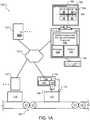
- FIG. 1Ashows an example of a laser marking system 100 usable to print codes on products.
- the system 100includes a product line configured to move products 110 through a facility, which can include one or more conveyor belts 105 and/or one or more other product movement mechanisms.
- the facilitycan be a product manufacturing facility, a product distribution facility, and/or other industrial/business facilities/buildings, and the product line can include a product packaging system, a product sorting system, and/or other product handling/management systems.
- the system 100includes one or more product interaction units 120 that are communicatively coupled with one or more control computers 125 through a network 130.
- the product interaction units 120can include various systems and devices, such as printers or RFID (radio frequency identification) stations for encoding information on the product 110, scales to weigh the product 110, various mechanical actuators to move the product 110 in particular ways, etc.
- the network 130can be a private network, a public network, a virtual private network, etc., and the network 130 can include wired and/or wireless networks.
- the system 100includes at least one laser marking device 140 that is configured and arranged in proximity to the product line to mark the products 110 with codes, as desired by a system operator.
- the "products" 110can be individual consumer units, boxes of units for delivery (dispatch units), and/or whole pallets of units or boxes, as well as the packaging or labelling for any of the foregoing.
- the laser marking device 140is a device that steers a laser beam to print codes on labels, which are then supplied to a label applicator that applies the labels to the product.
- the laser marking device 140effects the marking of products 110 (e.g., product labels) with product codes and is proximate to the product line in that it is close enough to print the codes directly on a merchandise unit, packaging for a merchandise unit, or a label for a merchandise unit.
- products 110e.g., product labels
- the laser marking device 140includes a laser source 142 configured to produce a laser printing beam 148, and an optics assembly 144 configured to direct the laser beam 148 in two orthogonal directions (e.g., using X and Y galvanometers) in accordance with control signals from electronics 146.
- the electronics 146can include one or more processors that execute instructions (e.g., stored in memory in the electronics 146) to control the operation of the laser marking device 140. Suitable processors include, but are not limited to, microprocessors, digital signal processors (DSP), microcontrollers, integrated circuits, application specific integrated circuits (ASICs), logic gate arrays and switching arrays.
- the electronics 146can also include one or more memories for storing instructions to be carried out by the one or more processors and/or for storing data developed during operation of the laser marking device 140.
- Suitable memoriesinclude, but are not limited to, Random Access Memory (RAM), Flash RAM, and electronic read-only memories (e.g., ROM, EPROM, or EEPROM).
- the electronics 146control operations of the laser source 142 and the optics assembly 144.
- the optics assembly 144can (in addition to redirecting the laser beam 148 toward the product 110) include low angle optics and reversed optics usable (under the control of the electronics 146) to steer the laser beam 148 between locations on the product 110, and dwell at the locations to mark the product 110.
- the "dwell time"can be adjusted based on the product 110 and the laser source 142 to ensure appropriate marks are created on the products 110. Note that the "dwell time" can include simply slowing the laser beam 148 down in the vicinity of the location to be marked, rather than requiring a complete stop of the laser beam 148. In any case, the electronics 146 cause the laser beam 148 to move quickly between the different dwell locations, e.g., such that the laser beam 148 does not leave a noticeable mark on the product 110 between these locations.
- the electronics 146can also be in communication with one or more sensors 135. These sensor(s) 135 can provide the electronics 146 with information about the products 110 on which the laser marking device 140 is to print. For instance, the sensor(s) 135 can indicate the location of a product 110 relative to the laser marking device 140, the direction that a product 110 is moving, a speed of a moving product 110, when a moving product 110 has been stopped, and when a product 110 is in the correct position to be printed upon.
- Suitable sensors 135can include, but are not limited to, a speed sensor for detecting the speed and/or direction that a product 110 is moving (e.g., encoders and resolvers) and a location sensor for indicating when a product 110 is positioned in front of the sensor 135 (e.g., a print trigger formed from a light beam generator and light sensor, where blocking of the light beam by the product 110 indicates the product 110 is in position for printing, or initiates a countdown for a time delay before the product 110 is in position for printing, e.g., a code position time delay that causes the code to be printed at a desired position on the product 110).
- a speed sensorfor detecting the speed and/or direction that a product 110 is moving
- a location sensorfor indicating when a product 110 is positioned in front of the sensor 135
- a print triggerformed from a light beam generator and light sensor, where blocking of the light beam by the product 110 indicates the product 110 is in position for printing, or initiates a countdown for
- a stop mechanismcan be used to temporarily stop the product 110 for printing with the laser beam 148.
- Such mechanismscan include a mechanical stop that prevents the product 110 from moving even though a conveyor belt 105 is still moving, or a functional control stop that temporarily stops the conveyor belt 105 (or other product movement system) and thus the product 110.
- the productcan be held stationary for the entire printing of the code, or the product can be stationary for only a portion of the time the laser printing of the code occurs, such as stopping the product mid-print, or stopping the product at the beginning of a print or at the end of the print.
- the laser marking device 140can employ pixel prioritization and motion-corrected dwell-location data generation techniques to print on moving products 110, such as described in U.S. Patent No. 7,167,194, issued on 23 January 2007 , and entitled, "PRINTING A CODE ON A PRODUCT".
- the laser source 142can be a continuous wave (CW) or pulsed laser light source, a fundamental mode or multi-mode laser light source, a CO 2 or a CO laser light source, or a combination thereof.
- the laser beam 148 formed by the laser source 142has enough power to alter an optical characteristic of the product 110 to form a spot when the laser beam 148 dwells at a location.
- the printing laser beam 148can alter a variety of optical characteristics of a product 110. For instance, the printing beam 148 can cause one or more layers of material to be ablated so the underlying layers are visible. Since upper layers of a material often have an ink layer on paper, removal of the ink layer leaves a spot where the paper is visible against the surrounding ink layer.
- the refractive characteristics of a materialcan also be altered.
- the printing beam 148can be used to print a code on a plastic such as a soft drink bottle.
- the printing beamalters the refractive characteristics of the plastic.
- the codeis easily visible since the eye can pick up the sections having contrasting refractive properties.
- the printing beamcan etch certain materials, or the product 110 can include a phase change material that changes (e.g., color) in response to laser light.
- a wide variety of laser sources 142can be used in the laser marking device 140, depending on the nature of the products 110 to be marked. This can include low power lasers, such as a CO 2 air cooled laser, e.g., a 25 Watt CO 2 laser, a 20 Watt CO 2 laser, a 15 Watt CO 2 laser, or a 13 Watt CO 2 laser. Note that, for low power lasers, the dwell time can often be increased as needed to ensure an adequate mark is made on the product 110.
- the locations on the product 110can be arranged such that the spots form symbols of a code on the product (e.g., pixels of an alphanumeric code).
- the symbols of the codecan be alphanumeric characters (e.g., user specified text or time/date information), logos or graphics, barcodes (e.g., one dimensional (ID) or two dimensional (2D) barcodes), or a combination of the foregoing.
- the electronics 146can control the optics assembly 144 to direct the laser printing beam 148 to dwell at different locations on the product 110 to mark the product in accordance with instructions received from a control computer 125, such as a computer 150.
- the computer 150includes a processor 152 and a memory 154, and the computer 150 can be coupled with the laser marking device 140 either directly or through the network 130 (as shown).
- the processor 152can be one or more hardware processors, which can each include multiple processor cores.
- the memory 154can include both volatile and non-volatile memory, such as RAM and Flash RAM.
- the computer 150can include various types of computer storage media and devices, which can include the memory 154, to store instructions of programs that run on the processor 152.
- a program 156presents a user interface (UI) 162 on a display device 160 of the computer 150, which can be operated using one or more input devices 158 of the computer 150 (e.g., keyboard and mouse).
- UIuser interface
- the display device 160 and/or input devices 158can also be integrated with each other and/or with the computer 150, such as in a tablet computer, where the one or more input devices 158 can be part of a touch screen display 160.
- the computer 150can be a wireless tablet device used as a handheld controller for the laser marking device 140.
- the program(s) 156can include a symbol grouping and striping laser marking program 156. Although shown in FIG. 1A as being included together in a program at the computer 150, other program configuration and distribution is possible. Two separate programs 156 can be used: a symbol grouping program 156 and a striping laser marking program 156. Further, as noted above, the electronics 146 can include a processor and a memory, such as the processor 152 and the memory 154, and so a program 156 can also be included in the electronics 146.
- a symbol grouping program 156resides at the computer 150 to provide the user interface 162, to assist in building the product code, and to define the groups for the product code; and a striping laser marking program 156 resides at the electronics 146 in the laser marking device 140.
- a product codeincludes both a sell-by-date 164 and a 2D barcode 166 (e.g., a QR (quick response) code).
- a QRquick response
- FIG. 1Ae.g., "08-05-18" for sell-by-date 164, is arbitrary in that the information included in the product codes will depend on the particular product and the time and/or location of its manufacture/distribution.
- Other codesare also possible, such as codes that include a logo or graphic and a ID barcode.
- FIG. 1Bshows two laser marking devices 140A mounted side-by-side at a label marking station, where each of the laser marking devices 140A is configured to direct its laser beam in two orthogonal directions (X & Y) across a wide field to mark a wide web foil 110A that will be attached to product packaging.
- a code striping techniqueemploys a symbol grouping technique to manage print time and quality.
- FIG. 2Ashows an example of a code 200 to be printed through a laser aperture 210.
- the code 200 in this exampleis two lines of text: "ABCD" over "1234".
- the aperture 210(shown here as very small for illustrative purposes only) is the area within which the laser (e.g., laser beam 148 in FIG. 1A ) can effectively print. Although this aperture 210 can be a physical window, this aperture 210 is typically a result of the limitations of the optics assembly (e.g., optics assembly 144 in FIG. 1A ). In general, the aperture for a steered laser beam marking device defines the area within which the optics assembly will allow the printing device to print (e.g., on a moving product 110 in FIG.
- not all symbols of the code 200can be printed through the aperture 210 at the same time, e.g., the symbol “A” 202 and the symbol “D” 204 are outside the aperture 210 when the symbols "B" and "C" are inside the aperture.
- each symbol of the code 200can be formed from pixels/spots, and the order of marking these pixels/spots changed to account for the space limitations of the aperture 210 and the time limitations for a product moving under the aperture 210.
- the data set used to direct the laser beam to the selected and ordered dwell-locations (for marking the pixels/spots)can be adjusted to account for a moving product, and the program(s) can also adjust the marking locations to compensate for any distortion introduced to the laser beam path by a lens in the optics assembly.
- FIG. 2Bshows an example of stripes 220 created for the code 200 of FIG. 2A .
- Stripingrefers to organizing a code (e.g., a list of control points for the laser beam, with an order of the control points to be marked) composed of symbols into a plurality of stripes or segments of data sets formed from those symbols.
- a programe.g., program 156, e.g., in electronics 146) organizes the code 200 into stripes 220 in a direction perpendicular to the motion of the product. In this example, the stripes are vertical for a horizontally moving product, but the stripes can also be horizontal for a vertically moving product.
- a first stripe 222includes the symbol “D” and the symbol “4"
- a second stripe 224includes the symbol “C” and the symbol “3”
- a third stripe 226includes the symbol “B” and the symbol “2”
- a fourth stripe 228includes the symbol “A” and the symbol “1”.
- the order of operations for the laser beam steering in this instanceis thus as follows: start with the first stripe 222 by marking the locations defining the "D" symbol 204, jump to and mark the locations of the next symbol "4" in the first stripe 222, then proceed with marking the second stripe 224, followed by the third stripe 226, and finish with the fourth stripe 228.
- the distance of laser beam jumpsshould be reduced as much as possible, and so the marking operations alternate between starting at the top of a stripe 220 and starting at the bottom of a stripe.
- the final symbol marked in this exampleis the "A" symbol 202.
- each stripe 220is assigned parameters, such as a print order and a "weight" based on size, location, number of pixels, and time to print the stripe.
- clipping correction techniquese.g., leading edge clipping correction and trailing edge clipping correction
- leading edge clipping correction and trailing edge clipping correctionare used for the stripes by adding an extra distance or a time delay between stripes to prevent clipping of a symbol by the laser marking device due to the print aperture of the laser marking device.
- the laser aperturewill be much larger, allowing for larger codes to be printed.
- the code 200can be understood as two sub-codes ("ABCD" and "1234") that can be spaced apart vertically by a distance 230.
- the print timeincrease due to the increased movement of the mirror(s) steering the laser beam
- the print qualitydecreases due to the mirror(s) moving at a very high speed when jumping between the first part of the code and the second part of the code.
- FIG. 2Bis just a simple example, and the issues of print time and print quality become more significant as the code complexity increases.
- FIG. 2Cshows an example of stripes created for a larger, matrix code 240 to be printed through a laser aperture.
- the code 240can be understood as four sub-codes 242, 244, 246, 248 that are replicated across a wide field of view for a laser marking device.
- the laser beam steering in this examplehas the same issue of larger jumps across a vertical distance 230, as addressed above, and the laser beam steering in this example also has to make a jump across a horizontal distance 250, where this distance 250 can also be increased.
- high speed jumpscan require a ramp down and stabilizing speed before printing the symbol after a large jump, which can result in poor print quality on the symbol that follows a large jump.
- the stripesare defined narrowly to require the symbols to exactly line up with each other in the specified direction (vertical in this example, see for example, FIG. 13B in U.S. Patent No. 7,046,267 ) then further issues can arise. If a user needs to rotate the code/image to be marked to compensate for a mechanical misalignment on a product line, the individual symbols of the code 240 may no longer be exactly aligned with each other, resulting is a separate "stripe" being created for each of the thirty two individual symbols of the code 240, which can result in even more large jumps for the laser beam steering.
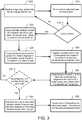
- FIG. 3shows an example of a process for symbol grouping and striping for wide field matrix laser marking.
- the processbegins by obtaining a code to be printed on products (e.g., labels for products) by a laser marking device (e.g., laser marking devices 140, 140A) configured to direct a laser beam in two orthogonal directions to move between different locations and to dwell at the different locations to form marks.
- a laser marking devicee.g., laser marking devices 140, 140A
- the processforms 310 the code for a wide field laser marking system using the received input.
- textcan be entered 305 by a user through a user interface (e.g., the UI 162), and this text is converted 310 to marking locations by a program (e.g., the program 156) using a selected font definition.
- a programe.g., the program 156
- datacan be entered 305 through the user interface (e.g., the UI 162), and this data can be converted 310 to marking locations of a ID or 2D barcode by a program (e.g., the program 156) using known barcode generation techniques.
- an imagecan be provided 305 (e.g., through the UI 162) and then processed 310 to determine marking locations where the laser will dwell.
- thiscan include using outlining techniques, as described in U.S. Patent No. 6,958,762, issued October 25, 2005 , and entitled "FILLING AN AREA OF AN IMAGE MARKED ON A MATERIAL WITH A LASER".
- Such an approachcan also be used for images of alphanumeric characters, and/or optical character recognition techniques can be used (e.g., by the program 156).
- some or all of a sub-codewill be repeated across a matrix of products (e.g., sheet 110B, which has a 6x4 matrix of product labels), and so the user interface can include functionality to facilitate this duplication of a sub-code when forming 310 the code for the wide field laser marking system.
- a matrix of productse.g., sheet 110B, which has a 6x4 matrix of product labels
- an image to be printedcan be received 305 along with X and Y coordinates corresponding to the two orthogonal directions (i.e., the unit dimensions of the matrix code, such as the 6x4 matrix of sub-codes shown for sheet 110B), and then the received image can be replicated 310 in accordance with the X and Y coordinates to form the code to be printed.
- 1Acan be used to create multiple images of a code to be printed by allowing the user to select a matrix size (e.g., 5x5 or other equal or different matrix units), a size for each cell in a grid for the matrix, and then design the first cell.
- the programcan then, by default, replicate the content into each cell of the grid for the matrix, and the user can also use the program providing the UI 162 to customize the content for each cell to have unique content.
- discrete symbols in the codeare grouped 320 with each other into separate symbol groups based on the locations of the discrete symbols within a total image area for the code.
- the grouping 320 of the discrete symbols in the codeis done using meta data stored in the image description for the code, such as described in further detail below in connection with FIG. 5A .
- the grouping 320 of the discrete symbols in the codeis done based on proximity of the discrete symbols to each other within the total image area for the code, such as by using a proximity metric to create the groups, as described in further detail below in connection with FIG. 5B .
- Other clustering algorithmscan also be used to group the discrete symbols in the code.
- the result of the grouping 320can be meta data that defines the groups and is stored in the image description for the code.
- FIG. 4Ashows an example of groups 402, 404, 406, 408 created for the code 240 from FIG. 2C .
- the striping algorithmcan then be applied at this macro level to the groups 402, 404, 406, 408, which are treated like individual symbols in the striping process, e.g., in accordance with grouping meta data for the code.
- Thiscan be understood as a macro-level striping.
- FIG. 4Bshows the example of groups 402, 404, 406, 408 of FIG. 4A organized into stripes 412, 414.
- the separate symbol groupsare organized 325 into stripes of groups in the direction perpendicular to the direction of product motion.
- the program and/or electronicsplaces each symbol group in one stripe, and does not divide a symbol group into multiple stripes. Further, the program and/or electronics avoids placing more than one symbol group (along a horizontal line, in this example) into a single vertical stripe.
- the discrete symbol groupsare represented by meta data defining groupings of discrete symbols.
- Symbol groupsare put into the same macro-level stripe if they line up with each other, e.g., in the direction perpendicular to the direction of product motion.
- this aligningincludes no tolerance allowance, and so a set of discrete symbol groups are organized into a stripe only if the bounding boxes/borders for those discrete symbol groups are 100% lined up with each other; if a bounding box/border is off by even a single pixel, a new stripe is created. It should be noted that such alignments of the discrete symbol groups will happen frequently in matrix marking applications.
- a level of toleranceis built into the system for creation of stripes. For example, a macro-level stripe can still be created if the discrete symbol groups are at least 99% lined up with each other, at least 98% lined up with each other, at least 97% lined up with each other, or at least 96% lined up with each other.
- the symbols in each respective symbol groupare organized 330 into one or more stripes in the direction perpendicular to the direction of motion of the product.
- the program and/or electronicsplaces each symbol within a group in one stripe, and does not divide a symbol into multiple stripes. Further, the program and/or electronics avoids placing more than one symbol (along a horizontal line, in this example) into a single vertical stripe.
- the discrete symbolsare represented by meta data defining groupings of marking locations.
- Symbolsare put into the same stripe if they line up with each other, e.g., in the direction perpendicular to the direction of product motion.
- this aligningincludes no tolerance allowance, and so a set of discrete symbols are organized into a stripe only if the bounding boxes/borders for those discrete symbols are 100% lined up with each other; if a bounding box/border is off by even a single pixel, a new stripe is created.
- a level of toleranceis built into the system for creation of stripes. For example, a symbol-level stripe can still be created if the discrete symbols are at least 99% lined up with each other, at least 98% lined up with each other, at least 97% lined up with each other, or at least 96% lined up with each other.
- FIG. 4Cshows symbols, within stripes 412, 414 of groups, having been organized into additional stripes.
- group stripe 412contains symbol group 404, organized into four stripes 422, and contains symbol group 408 organized into four stripes 424.
- group stripe 414contains symbol group 402, organized into four stripes 428, and contains symbol group 406 organized into four stripes 426.
- the stripeshave been prioritized for printing.
- FIG. 4Bshows that the laser starts and completes stripe 412 before proceeding with stripe 414
- FIG. 4Cshows that the laser starts and completes each stripe within a group, in the assigned order, before proceeding to the next group in the macro-stripe, and then to the next macro-stripe.
- the single headed arrowsindicate the order of operations for the laser beam steering. Comparing FIG. 4C with FIG. 2C , it can be seen that the same code is marked using substantially fewer large jumps (three instead of nine) for the steered laser beam, e.g., reducing the number of large, high speed galvanometer jumps improves print quality, and reducing or eliminating the number of long, back and forth galvanometers jumps improves print speed.
- laser steering mirrorscan be used much more efficiently, and even if the image of the code were rotated slightly (e.g., to compensate for a mechanical misalignment), the macro-groups of symbols will still reduce the number laser beam jumps, thereby improving print time and print quality.
- the processcan include assigning 335 a group print priority to the separate symbol groups in accordance with a time at which each respective symbol group enters the print aperture of the laser marking device, and assigning 335, for each of the separate symbol groups having two or more stripes, a stripe print priority to the two or more stripes in accordance with a time at which each respective stripe enters the print aperture of the laser marking device.
- the symbol groupings and print prioritiescan be shown 340 to the user (e.g., through UI 162) such as represented in FIGs. 4A-4C , and the user is then asked to confirm the groupings and print priorities.
- no user interactionis employed to confirm the symbol groupings and print priorities before proceeding with clipping correction using the defined stripes and print priorities.
- the symbol groupingscan be shown 340 to the user (e.g., through UI 162), and the user is then asked to confirm the groupings, but the assignment of print priorities during the striping can be performed without user interaction, e.g., in real time at the laser printer electronics, along with the clipping correction using the defined stripes and print priorities (e.g., symbol level stripes in a queue, where the order of the stripes in the queue represents the print priorities).
- the defined stripes and print prioritiese.g., symbol level stripes in a queue, where the order of the stripes in the queue represents the print priorities.
- clipping correctioninvolves adding 350 an extra distance or a time delay between stripes to prevent clipping (of a symbol or symbol group) by the laser marking device due to the print aperture of the laser marking device.
- These stripescan be the stripes formed from the groups of symbols, the stripes formed within each group of symbols, or both.
- the clipping correction 350performs on the symbol level stripes and not the macro-stripes.
- the more than one level of striping being describedcan be applied recursively and can scale beyond two levels, where the levels of macro-stripes help to define the order in which the lower level stripes for the symbols will be marked, and the clipping correction techniques can still be applied to these various manners of organizing the code into stripes.
- the laser marking deviceis caused 355 to direct the laser beam in accordance with the separate symbol groups, including using the extra distance or the time delay between the stripes to prevent clipping.
- the laser marking devicecan be caused 355 to direct the laser beam to print the separate symbol groups in an order of the group print priority and to print the stripes within each symbol group in an order of the stripe print priority, such as shown, for example, in FIGs. 4B and 4C .
- extra distance and/or time delaycan be added, as needed, between stripes to prevent leading edge clipping and trailing edge clipping.
- Leading edge clippingmay occur (a) when a product is moving too quickly past the laser print window (aperture), and the laser cannot complete its printing, and/or (b) when the printing system needs a high laser dwell time to print each pixel/spot on a product's material, and the laser cannot complete its printing.
- a trailing portion of the codeis thus "clipped" by the leading edge of the laser's aperture, which limits the laser beam from reaching a desired location on the moving product.
- the printing system"runs out” of aperture when trying to print on a fast-moving product or when a high dwell time is needed.
- leading edge clippingsee FIGs. 15A-15E and column 18, line 17, to column 21, line 56, of U.S. Patent No. 7,046,267 .
- a clipping correction moduleuses a trigger input (e.g., from sensor 135 in FIG. 1A ) to sense a leading edge of a product for a next print job, which can be put into a clipping correction processing queue.
- the clipping correction modulecan poll the queue and run clipping correction on the next job ready to print.
- the clipping correction moduleonly uses the stripes and velocity, and does not calculate time. Use of such a queue allows a trigger to be received while the clipping correction module is running clipping correction for a previously triggered print job, which can facilitate real-time clipping correction during laser marking.
- an encoder and/or resolvercan be used as a sensor for product velocity.
- printing routines/drivers for the laser marking devicetrack the distance a product has moved using an encoder to determine when to start printing.
- the encodere.g., sensor 135 coupled with electronics 146 by wired or wireless connection
- the usersets the trigger distance while taking into account the desired location of the print zone on the product, and the laser will start to print when the product's position has traveled the trigger distance (set by the user) minus the start offset set by the clipping correction module from the trigger location.
- the size/length of the productis sensed by the system, or is otherwise known by the system, and the trigger distance is determined automatically.
- the speed information provided by the encodercan be used as follows.
- the result of Time x (Distance/Time)is distance.
- Spreadingallows each stripe to be printed on the product as the product passes through the aperture. Spreading can add equal visual spaces between adjacent stripes such that adjacent stripes are equidistant across an entire printed image. Note that the reason for spreading is to push all stripe print zones back into the aperture by an equal amount while they are printing. This prevents the stripes from running into the aperture wall and clipping.
- the clipping correction modulecalculates the minimum space(s) needed to fit all the stripes in the desired print zone and use as little space on the product as possible.
- the printing routines/driverstrack the encoder to know when to start printing.
- the start offset valuewill cause the printing routines/drivers to start printing sooner than the "Trigger Distance" (e.g., as set by the user) by an amount equal to the start offset.
- the clipping correction modulecan also output another value to the real-time printing routines/drivers: the Clipping Correction Value, which indicates the offset for in-between stripes to adjust for clipping while printing.
- the printed image of the codemay thus be spread horizontally to prevent clipping, but it is still readable.
- Trailing edge clippingmay occur when the printing system tries to (a) print an image on a product that is moving too slowly past the laser print window (aperture), and/or (b) print a long image on a product, e.g., total length of image is longer than the aperture.
- the desired print location on the product to print a symbol of the codedoes not enter the aperture on time as expected, and the "trailing edge" of the aperture limits the print beam from reaching the desired location on the product.
- one or more symbols of the code (or portion(s) thereof)are printed in the wrong location on the product or symbols are printed on top of each other (overlapping symbols).
- the clipping correction moduleprovides real-time trailing edge clipping correction to print stripes on a product moving at a slow speed or to print stripes of codes that are longer than the aperture. Trailing edge clipping correction turns off the laser (or redirects the laser to a beam dump) and delays printing until a proper location (print zone for a stripe) on the product has entered the aperture.
- the clipping correction module or the real-time printing routines/driversreevaluate the speed input between every printed stripe. If the speed of the product has changed, the clipping correction module updates the Clipping Correction Value in real-time. For example, if the clipping correction module senses that the speed of the product has increased while or after the laser prints a given stripe, the clipping correction module can update, i.e., increase, the Clipping Correction Value to increase spreading. Thus, the spaces between stripes need not be equal. Moreover, if the speed of the product decreases, the clipping correction module adds a time delay to wait for a desired print zone to enter the aperture before printing the next stripe. For further details regarding such update clipping correction, see FIGs. 14D-14E and column 23, lines 9-56, of U.S. Patent No. 7,046,267 .
- the striping, leading edge clipping correction, trailing edge clipping correction and update clipping correctioncan be performed in real-time during operation of the laser marking device. In some implementations, one or more of these are done in advance of a particular printing job. Further, the techniques described above can be implemented using software, firmware, hardware, and combinations thereof. For example, in some implementations, an image processing module organizes an image of the code into stripes and sends the stripes to a clipping correction module.
- a striping module at the laser printergenerates symbol level stripes for a code from a computer in accordance with one or more levels of macro (grouped symbol) striping, e.g., in accordance with meta data stored in an image description for the code.
- the striping modulesends the stripes to a first-in-first-out queue, which is accessed by the clipping correction module; the striping module feeds the symbol level stripes to the queue in the order determined by the macro-stripes of the symbol groups.
- the clipping correction modulereceives the stripes, a trigger input to start printing, and a velocity input, and outputs a clipping correction value to real-time printing routines/drivers, which use the value to control printing by the laser marking device, e.g., on a moving product. Further, the clipping correction module or the printing routines/drivers can determine whether a velocity of the product has changed, and if so, the clipping correction module determines a new clipping correction value.
- the grouping 320 of nearby fields of marking locationscan be done using meta data stored in the image description for the code, or can be done automatically, e.g., using a proximity metric to create the groups.
- FIG. 5Ashows an example of grouping 320 discrete symbols in a code into separate symbol groups based on locations, which are defined by meta data generated for the code.
- An example of a UI screen 500is shown, as can be used in the UI 162 of FIG. 1A .
- the userpicks an image size and creates an image 510 to be printed.
- the useralso defines the X and Y (width and height) coordinates for the full code to be printed.
- the programe.g., program 1566 then replicates the image 510 across the full dimensions of the code to create the matrix code.
- the matrix codeis 3x3, i.e., the image 510 (containing a code of "ABC" over "123") is replicated eight times to fill out a 3x3 product matrix.
- FIG. 5Bshows another example of grouping discrete symbols in a code into separate symbol groups based on locations, where proximity of the locations are used to form the groups, as determined by the program and/or the user.
- An example of a UI screen 550is shown, as can be used in the UI 162 of FIG. 1A .
- the usermanually places each of the images to be printed into the code area (width and height).
- the programe.g., program 156) determines the groupings by defining a containing boundary for each of the discrete symbols and grouping discrete symbols whose containing boundaries overlap each other.
- the containing boundary for each discrete symbolcan have various shapes, such as a circle, as shown in FIG. 5B .
- the programcan identify each character in the image area, such as characters 560, 562, 564, 566, 568, and also place an imaginary circle at a fixed size around each identified character.
- the circleshave a diameter equal to one and half times a size of the characters, but other sizes for the circles (or other containing shapes) are also possible provided the shape is sized to be larger than the characters.
- the size (and potentially the shape as well) of the containing boundary for each discrete symbolis set in accordance with user input.
- the programgroups any characters whose containing boundaries overlap.
- a character that does not have a containing boundary that overlaps (directly or through one or more intermediate containing boundaries) with another containing boundaryis considered a different group.
- identified characters 560, 562are included in symbol group 570 because their containing boundaries 560A, 562A overlap
- identified characters 564, 566, 568are included in symbol group 575 because their containing boundaries overlap.
- identified character 564has a containing boundary that does not directly overlap with the containing boundary of identified character 568, but it does overlap indirectly through identified character 566.
- symbol group 575is shown in a location that is offset from the usual matrix code to highlight that this approach allows for the random placement of symbols within the code area, and the program will automatically identify appropriate groups of symbols in the code.
- Embodiments of the subject matter and the functional operations described in this specificationcan be implemented in digital electronic circuitry, or in computer software, firmware, or hardware, including the structures disclosed in this specification and their structural equivalents, or in combinations of one or more of them.
- Embodiments of the subject matter described in this specificationcan be implemented using one or more modules of computer program instructions encoded on a computer-readable medium for execution by, or to control the operation of, data processing apparatus.
- the computer-readable mediumcan be a manufactured product, such as hard drive in a computer system or an optical disc sold through retail channels, or an embedded system.
- the computer-readable mediumcan be acquired separately and later encoded with the one or more modules of computer program instructions, such as by delivery of the one or more modules of computer program instructions over a wired or wireless network.
- the computer-readable mediumcan be a machine-readable storage device, a machine-readable storage substrate, a memory device, or a combination of one or more of them.
- data processing apparatusencompasses all apparatus, devices, and machines for processing data, including by way of example a programmable processor, a computer, or multiple processors or computers, and the term “computer readable medium” indicates a tangible (non-transitory) medium on which instructions can be encoded and read by a data processing apparatus.
- a computer program(also known as a program, software, software application, script, or code) can be written in any form of programming language, including compiled or interpreted languages, declarative or procedural languages, and it can be deployed in any form, including as a stand-alone program or as a module, component, subroutine, or other unit suitable for use in a computing environment.
- a computer programdoes not necessarily correspond to a file in a file system.
- a programcan be stored in a portion of a file that holds other programs or data (e.g., one or more scripts stored in a markup language document), in a single file dedicated to the program in question, or in multiple coordinated files (e.g., files that store one or more modules, sub-programs, or portions of code).
- a computer programcan be deployed to be executed on one computer or on multiple computers that are located at one site or distributed across multiple sites and interconnected by a communication network.
- the processes and logic flows described in this specificationcan be performed by one or more programmable processors executing one or more computer programs to perform functions by operating on input data and generating output.
- the processes and logic flowscan also be performed by, and apparatus can also be implemented as, special purpose logic circuitry, e.g., an FPGA (field programmable gate array) or an ASIC (application-specific integrated circuit).
- processors suitable for the execution of a computer programinclude, by way of example, both general and special purpose microprocessors, and any one or more processors of any kind of digital computer.
- a processorwill receive instructions and data from a read-only memory or a random access memory or both.
- the essential elements of a computerare a processor for performing instructions and one or more memory devices for storing instructions and data.
- a computerwill also include, or be operatively coupled to receive data from or transfer data to, or both, one or more mass storage devices for storing data, e.g., magnetic, magneto-optical disks, or optical disks.
- mass storage devicesfor storing data, e.g., magnetic, magneto-optical disks, or optical disks.
- a computerneed not have such devices.
- a computercan be embedded in another device, e.g., a mobile telephone, a personal digital assistant (PDA), a mobile audio or video player, a game console, a Global Positioning System (GPS) receiver, or a portable storage device (e.g., a universal serial bus (USB) flash drive), to name just a few.
- PDApersonal digital assistant
- GPSGlobal Positioning System
- USBuniversal serial bus
- Non-volatile memorymedia and memory devices
- semiconductor memory devicese.g., EPROM (Erasable Programmable Read-Only Memory), EEPROM (Electrically Erasable Programmable Read-Only Memory), and flash memory devices
- magnetic diskse.g., internal hard disks or removable disks
- magneto-optical diskse.g., magneto-optical disks
- CD-ROM and DVD-ROM diskse.g., CD-ROM and DVD-ROM disks.
- the processor and the memorycan be supplemented by, or incorporated in, special purpose logic circuitry.
- embodiments of the subject matter described in this specificationcan be implemented on a computer having a display device, e.g., an LCD (liquid crystal display) display device, an OLED (organic light emitting diode) display device, or another monitor, for displaying information to the user, and a keyboard and a pointing device, e.g., a mouse or a trackball, by which the user can provide input to the computer.
- a display devicee.g., an LCD (liquid crystal display) display device, an OLED (organic light emitting diode) display device, or another monitor
- a keyboard and a pointing devicee.g., a mouse or a trackball
- Other kinds of devicescan be used to provide for interaction with a user as well; for example, feedback provided to the user can be any form of sensory feedback, e.g., visual feedback, auditory feedback, or tactile feedback; and input from the user can be received in any form, including acoustic, speech, or tactile input.
Landscapes
- Engineering & Computer Science (AREA)
- Physics & Mathematics (AREA)
- Optics & Photonics (AREA)
- Theoretical Computer Science (AREA)
- General Engineering & Computer Science (AREA)
- Human Computer Interaction (AREA)
- Mechanical Engineering (AREA)
- General Physics & Mathematics (AREA)
- Plasma & Fusion (AREA)
- Laser Beam Processing (AREA)
- Laser Beam Printer (AREA)
- Thermal Transfer Or Thermal Recording In General (AREA)
- Printers Characterized By Their Purpose (AREA)
Description
- This specification relates to industrial printing systems, and in particular, systems and techniques relating to laser printing product codes on the packaging of products in a manufacturing or distribution facility.
- Various industrial printing technologies are known and enable the printing of important information (e.g., sell by dates) on packaging. Dot-matrix type laser marking devices have been used to print identification code on commercial products. These codes are readily observable on common products such as soda cans, cosmetics, pet food containers, etc. Some government regulatory agencies, such as the Food and Drug Administration in the U.S., may require certain products to have such codes. These codes often include information that is unique to the time and place at which the product is manufactured. For instance, many codes communicate a batch number associated with a product. Many codes go further and indicate the actual time and date of manufacture. Because some codes relate to unique manufacturing parameters (e.g., time and date), some codes cannot be pre-printed on a label for a product. Hence, a code is often printed on the label after the product is manufactured.
U.S. Patent No. 7,046,267 describes a laser printing system that organizes an image into a sequence of "stripes" for laser printing so as to provide an efficient print order of characters and symbols, which can improve printing by using more of the laser's exposure window (aperture) and reducing an amount of laser deflection motion between marking operations.US 7,167,194 describes a printing method using a printing system that prints a code on a product moving in a direction. The code is constructed from a plurality of pixels in a first data set indicating the positions of the pixels and generates a corrected data set indicating the position that each pixel would occupy if each pixel was moved at the velocity of the product until the pixel was printed. US 6,061,081 describes a scan-type laser marking device that includes a scanning speed setting device.US 4,636,043 describes a laser beam scanning device that includes an optical system that is mounted on a carriage which is movable back and forth along a linear path in front of a target area and which is parallel to the optical path of a projected laser beam.- This specification describes technologies relating to industrial printing systems, and in particular, systems and techniques relating to laser printing product codes on the packaging of products in a manufacturing or distribution facility.
- The present invention is directed to a method that includes: obtaining a code to be printed on one or more products by a laser marking device configured to direct a laser beam in two orthogonal directions to move between different locations and to dwell at the different locations to form marks on the one or more products; grouping discrete symbols in the code with each other into separate symbol groups based on locations of the discrete symbols in the code; organizing the separate symbol groups into one or more macro-level stripes in a direction perpendicular to a direction of motion of the one or more products in a product line configured to move products through a facility; organizing one or more symbols in each respective symbol group into one or more stripes in a direction perpendicular to a direction of motion of the one or more products in a product line configured to move products through a facility; adding an extra distance or a time delay between stripes in at least one of the separate symbol groups to prevent clipping of a symbol by the laser marking device due to a print aperture of the laser marking device; and causing the laser marking device to direct the laser beam in accordance with the separate symbol groups, including using the extra distance or the time delay between the stripes in the at least one of the separate symbol groups. These and other embodiments can optionally include one or more of the following features.
- The method can include: assigning a group print priority to the separate symbol groups in accordance with a time at which each respective symbol group enters the print aperture of the laser marking device; and assigning, for each of the separate symbol groups having two or more stripes, a stripe print priority to the two or more stripes in accordance with a time at which each respective stripe enters the print aperture of the laser marking device; wherein causing the laser marking device to direct the laser beam in accordance with the separate symbol groups includes causing the laser marking device to direct the laser beam to print the separate symbol groups in an order of the group print priority and to print the two or more stripes within a symbol group in an order of the stripe print priority.
- The method can include: that assigning the group print priority includes treating each of the stripes of groups as a single group for priority assignment. The separate symbol groups organized into stripes of groups can include at least four separate symbol groups. Obtaining the code to be printed on the one or more products by the laser marking device can include: receiving an image to be printed; receiving X and Y coordinates corresponding to the two orthogonal directions; and replicating the image in accordance with the X and Y coordinates to form the code to be printed.
- Grouping the discrete symbols in the code can include grouping the discrete symbols in the code based on proximity of the discrete symbols to each other. Grouping the discrete symbols in the code can include: defining a containing boundary for each of the discrete symbols in the code; and grouping discrete symbols whose containing boundaries overlap each other. The containing boundary for each discrete symbol can be set as a circle having a diameter equal to one and a half times a size of the symbol. The containing boundary for each discrete symbol can be set in accordance with user input.
- The method is implemented using a computer readable medium encoding instructions operable to cause a data processing apparatus to perform operations of the one or more methods. Further a system includes: a product line configured to move products through a facility; a laser marking device arranged with respect to the product line and configured to direct a laser beam in two orthogonal directions to move between different locations and to dwell at the different locations to form marks on the products; and a laser marking device controller communicatively coupled with the laser marking device, the laser marking device controller being configured to obtain a code to be printed on the products, group discrete symbols in the code with each other into separate symbol groups based on locations of the discrete symbols in the code, organize the separate symbol groups into one or more macro-level stripes in a direction perpendicular to a direction of motion of the one or more products in a product line configured to move products through a facility; organize one or more symbols in each respective symbol group into one or more stripes in a direction perpendicular to a direction of motion of the products in the product line, add an extra distance or a time delay between stripes in at least one of the separate symbol groups to prevent clipping of a symbol by the laser marking device due to a print aperture of the laser marking device, and cause the laser marking device to direct the laser beam in accordance with the separate symbol groups, including using the extra distance or the time delay between the stripes in the at least one of the separate symbol groups. These and other embodiments can optionally include one or more of the following features.
- The laser marking device controller can be configured to assign a group print priority to the separate symbol groups in accordance with a time at which each respective symbol group enters the print aperture of the laser marking device, assign, for each of the separate symbol groups having two or more stripes, a stripe print priority to the two or more stripes in accordance with a time at which each respective stripe enters the print aperture of the laser marking device, and cause the laser marking device to direct the laser beam to print the separate symbol groups in an order of the group print priority and to print the two or more stripes within a symbol group in an order of the stripe print priority.
- The laser marking device controller can be configured to treat each of the stripes of groups as a single group for priority assignment. The separate symbol groups organized into stripes of groups can include at least four separate symbol groups. The laser marking device controller can be configured to obtain the code to be printed on the one or more products by the laser marking device by receiving an image to be printed, receive X and Y coordinates corresponding to the two orthogonal directions, and replicate the image in accordance with the X and Y coordinates to form the code to be printed.
- The laser marking device controller can be configured to group the discrete symbols in the code based on proximity of the discrete symbols to each other. The laser marking device controller can be configured to group the discrete symbols in the code by defining a containing boundary for each of the discrete symbols in the code, and grouping discrete symbols whose containing boundaries overlap each other. The containing boundary for each discrete symbol can be set as a circle having a diameter equal to one and a half times a size of the symbol. The containing boundary for each discrete symbol can be set in accordance with user input. The laser marking device controller can include: electronics that are integrated with the laser marking device; and a computer that is separate from the laser marking device. The facility can be a product manufacturing facility and the product line is a product packaging system.
- Various embodiments of the subject matter described in this specification can be implemented to realize one or more of the following advantages. The effective use of a laser marking device's exposure window (aperture) can be increased, and an amount of laser beam deflection motion between dwell locations (where marks are made) can be reduced. For wide field laser marking applications, e.g., code matrix marking applications, a code striping technique can employ a symbol grouping technique to reduce print time and/or improve print quality by determining an efficient print order of different portions of a complex code/image. In some cases, up to a 25% reduction in print time can be achieved on typical images in wide field, code matrix laser marking applications.
- Clipping correction can be implemented using the stripes formed for the code so as to successfully print (without clipping) codes on slow and fast moving products, as well as products that change speed, without requiring control of the speed of the product on a product line. Moreover, the systems and techniques described are also usable (and beneficial) with products that are stationary during a laser printing operation. For example, if the product is held temporarily stationary on a product line at a laser printing station for the entire printing of a code, the systems and techniques described can still improve the laser printing by optimizing the mirror movement to minimize jump distances, which reduces the overall print time, resulting in higher throughput on a product line.
- The details of one or more embodiments of the subject matter described in this specification are set forth in the accompanying drawings and the description below.
FIG. 1A shows an example of a laser marking system usable to print codes on products.FIG. 1B shows an example of a laser marking device usable to print codes across a wide field.FIG. 2A shows an example of a code to be printed through a laser aperture.FIG. 2B shows an example of stripes created for the code ofFIG. 2A .FIG. 2C shows an example of stripes created for a larger, matrix code to be printed through a laser aperture.FIG. 3 shows an example of a process for symbol grouping and striping for wide field matrix laser marking.FIG. 4A shows an example of groups created for the code fromFIG. 2C .FIG. 4B shows the example of groups ofFIG. 4A organized into stripes.FIG. 4C shows symbols, within stripes of groups, having been organized into additional stripes.FIG. 5A shows an example of grouping discrete symbols in a code into separate symbol groups based on proximity.FIG. 5B shows another example of grouping discrete symbols in a code into separate symbol groups based on proximity.- Like reference numbers and designations in the various drawings indicate like elements.
FIG. 1A shows an example of alaser marking system 100 usable to print codes on products. Thesystem 100 includes a product line configured to moveproducts 110 through a facility, which can include one ormore conveyor belts 105 and/or one or more other product movement mechanisms. The facility can be a product manufacturing facility, a product distribution facility, and/or other industrial/business facilities/buildings, and the product line can include a product packaging system, a product sorting system, and/or other product handling/management systems.- In some implementations, the
system 100 includes one or moreproduct interaction units 120 that are communicatively coupled with one ormore control computers 125 through anetwork 130. Theproduct interaction units 120 can include various systems and devices, such as printers or RFID (radio frequency identification) stations for encoding information on theproduct 110, scales to weigh theproduct 110, various mechanical actuators to move theproduct 110 in particular ways, etc. Thenetwork 130 can be a private network, a public network, a virtual private network, etc., and thenetwork 130 can include wired and/or wireless networks. For additional details regarding systems and techniques for product line configuration, seeU.S. Patent No. 7,191,019, issued on 13 March 2007 , and entitled, "DYNAMIC LINE CONFIGURATION". - The
system 100 includes at least one laser marking device 140 that is configured and arranged in proximity to the product line to mark theproducts 110 with codes, as desired by a system operator. Note that the "products" 110 can be individual consumer units, boxes of units for delivery (dispatch units), and/or whole pallets of units or boxes, as well as the packaging or labelling for any of the foregoing. Thus, in some implementations, the laser marking device 140 is a device that steers a laser beam to print codes on labels, which are then supplied to a label applicator that applies the labels to the product. In any case, the laser marking device 140 effects the marking of products 110 (e.g., product labels) with product codes and is proximate to the product line in that it is close enough to print the codes directly on a merchandise unit, packaging for a merchandise unit, or a label for a merchandise unit. - The laser marking device 140 includes a
laser source 142 configured to produce alaser printing beam 148, and anoptics assembly 144 configured to direct thelaser beam 148 in two orthogonal directions (e.g., using X and Y galvanometers) in accordance with control signals fromelectronics 146. Theelectronics 146 can include one or more processors that execute instructions (e.g., stored in memory in the electronics 146) to control the operation of the laser marking device 140. Suitable processors include, but are not limited to, microprocessors, digital signal processors (DSP), microcontrollers, integrated circuits, application specific integrated circuits (ASICs), logic gate arrays and switching arrays. Theelectronics 146 can also include one or more memories for storing instructions to be carried out by the one or more processors and/or for storing data developed during operation of the laser marking device 140. Suitable memories include, but are not limited to, Random Access Memory (RAM), Flash RAM, and electronic read-only memories (e.g., ROM, EPROM, or EEPROM). - The
electronics 146 control operations of thelaser source 142 and theoptics assembly 144. Theoptics assembly 144 can (in addition to redirecting thelaser beam 148 toward the product 110) include low angle optics and reversed optics usable (under the control of the electronics 146) to steer thelaser beam 148 between locations on theproduct 110, and dwell at the locations to mark theproduct 110. The "dwell time" can be adjusted based on theproduct 110 and thelaser source 142 to ensure appropriate marks are created on theproducts 110. Note that the "dwell time" can include simply slowing thelaser beam 148 down in the vicinity of the location to be marked, rather than requiring a complete stop of thelaser beam 148. In any case, theelectronics 146 cause thelaser beam 148 to move quickly between the different dwell locations, e.g., such that thelaser beam 148 does not leave a noticeable mark on theproduct 110 between these locations. - The
electronics 146 can also be in communication with one ormore sensors 135. These sensor(s) 135 can provide theelectronics 146 with information about theproducts 110 on which the laser marking device 140 is to print. For instance, the sensor(s) 135 can indicate the location of aproduct 110 relative to the laser marking device 140, the direction that aproduct 110 is moving, a speed of a movingproduct 110, when a movingproduct 110 has been stopped, and when aproduct 110 is in the correct position to be printed upon.Suitable sensors 135 can include, but are not limited to, a speed sensor for detecting the speed and/or direction that aproduct 110 is moving (e.g., encoders and resolvers) and a location sensor for indicating when aproduct 110 is positioned in front of the sensor 135 (e.g., a print trigger formed from a light beam generator and light sensor, where blocking of the light beam by theproduct 110 indicates theproduct 110 is in position for printing, or initiates a countdown for a time delay before theproduct 110 is in position for printing, e.g., a code position time delay that causes the code to be printed at a desired position on the product 110). - Moreover, in some implementations, a stop mechanism can be used to temporarily stop the
product 110 for printing with thelaser beam 148. Such mechanisms can include a mechanical stop that prevents theproduct 110 from moving even though aconveyor belt 105 is still moving, or a functional control stop that temporarily stops the conveyor belt 105 (or other product movement system) and thus theproduct 110. The product can be held stationary for the entire printing of the code, or the product can be stationary for only a portion of the time the laser printing of the code occurs, such as stopping the product mid-print, or stopping the product at the beginning of a print or at the end of the print. Moreover, in some implementations, the laser marking device 140 can employ pixel prioritization and motion-corrected dwell-location data generation techniques to print on movingproducts 110, such as described inU.S. Patent No. 7,167,194, issued on 23 January 2007 , and entitled, "PRINTING A CODE ON A PRODUCT". - The
laser source 142 can be a continuous wave (CW) or pulsed laser light source, a fundamental mode or multi-mode laser light source, a CO2 or a CO laser light source, or a combination thereof. Thelaser beam 148 formed by thelaser source 142 has enough power to alter an optical characteristic of theproduct 110 to form a spot when thelaser beam 148 dwells at a location. Theprinting laser beam 148 can alter a variety of optical characteristics of aproduct 110. For instance, theprinting beam 148 can cause one or more layers of material to be ablated so the underlying layers are visible. Since upper layers of a material often have an ink layer on paper, removal of the ink layer leaves a spot where the paper is visible against the surrounding ink layer. The refractive characteristics of a material can also be altered. For instance, theprinting beam 148 can be used to print a code on a plastic such as a soft drink bottle. The printing beam alters the refractive characteristics of the plastic. The code is easily visible since the eye can pick up the sections having contrasting refractive properties. - In addition, the printing beam can etch certain materials, or the
product 110 can include a phase change material that changes (e.g., color) in response to laser light. Thus, a wide variety oflaser sources 142 can be used in the laser marking device 140, depending on the nature of theproducts 110 to be marked. This can include low power lasers, such as a CO2 air cooled laser, e.g., a 25 Watt CO2 laser, a 20 Watt CO2 laser, a 15 Watt CO2 laser, or a 13 Watt CO2 laser. Note that, for low power lasers, the dwell time can often be increased as needed to ensure an adequate mark is made on theproduct 110. - The locations on the
product 110 can be arranged such that the spots form symbols of a code on the product (e.g., pixels of an alphanumeric code). The symbols of the code can be alphanumeric characters (e.g., user specified text or time/date information), logos or graphics, barcodes (e.g., one dimensional (ID) or two dimensional (2D) barcodes), or a combination of the foregoing. For example, theelectronics 146 can control theoptics assembly 144 to direct thelaser printing beam 148 to dwell at different locations on theproduct 110 to mark the product in accordance with instructions received from acontrol computer 125, such as acomputer 150. - The
computer 150 includes aprocessor 152 and amemory 154, and thecomputer 150 can be coupled with the laser marking device 140 either directly or through the network 130 (as shown). Theprocessor 152 can be one or more hardware processors, which can each include multiple processor cores. Thememory 154 can include both volatile and non-volatile memory, such as RAM and Flash RAM. Thecomputer 150 can include various types of computer storage media and devices, which can include thememory 154, to store instructions of programs that run on theprocessor 152. - In some implementations, a
program 156 presents a user interface (UI) 162 on adisplay device 160 of thecomputer 150, which can be operated using one ormore input devices 158 of the computer 150 (e.g., keyboard and mouse). Note that while shown as separate devices inFIG. 1 , thedisplay device 160 and/orinput devices 158 can also be integrated with each other and/or with thecomputer 150, such as in a tablet computer, where the one ormore input devices 158 can be part of atouch screen display 160. Thus, thecomputer 150 can be a wireless tablet device used as a handheld controller for the laser marking device 140. - The program(s) 156 can include a symbol grouping and striping
laser marking program 156. Although shown inFIG. 1A as being included together in a program at thecomputer 150, other program configuration and distribution is possible. Twoseparate programs 156 can be used: asymbol grouping program 156 and a stripinglaser marking program 156. Further, as noted above, theelectronics 146 can include a processor and a memory, such as theprocessor 152 and thememory 154, and so aprogram 156 can also be included in theelectronics 146. In some implementations, asymbol grouping program 156 resides at thecomputer 150 to provide theuser interface 162, to assist in building the product code, and to define the groups for the product code; and a stripinglaser marking program 156 resides at theelectronics 146 in the laser marking device 140. - Thus, for example, by doing all the stripe creation entirely within the
printer electronics 146, thecomputer 150 need not be provided any information regarding the print direction for the product code being used with the product line. In the example shown, a product code includes both a sell-by-date 164 and a 2D barcode 166 (e.g., a QR (quick response) code). Note that the example used inFIG. 1A , e.g., "08-05-18" for sell-by-date 164, is arbitrary in that the information included in the product codes will depend on the particular product and the time and/or location of its manufacture/distribution. Other codes are also possible, such as codes that include a logo or graphic and a ID barcode. - Because the
products 110 are on a moving product line, and theproducts 110 themselves may be moving during laser printing thereon, there is a limited amount of time available for printing on each product. Moreover, as the field of view of the laser is increased, so as to enable printing a code on multiple products per code print sequence, the available time is limited still further. For example,FIG. 1B shows twolaser marking devices 140A mounted side-by-side at a label marking station, where each of thelaser marking devices 140A is configured to direct its laser beam in two orthogonal directions (X & Y) across a wide field to mark awide web foil 110A that will be attached to product packaging. - Note that increasing the distance (Z) between the
laser marking devices 140A and thewide web foil 110A increases the effective aperture of the laser for marking, which allows for awider sheet 110B and more product cover labels to be marked with a single, large matrix code composed of sub-codes 164A for each individualproduct cover label 110C. For a given type of laser and speed of laser beam steering, the upper limit on the size of this single, large matrix code depends on the material being marked (i.e., how much dwell time is needed between the different locations to form the marks making up the code) and the selected ordering of the marking locations (i.e., how many jumps of what distances does the laser beam need to make to mark the code). To handle such wider field laser marking applications, a code striping technique employs a symbol grouping technique to manage print time and quality. FIG. 2A shows an example of acode 200 to be printed through alaser aperture 210. Thecode 200 in this example is two lines of text: "ABCD" over "1234". The aperture 210 (shown here as very small for illustrative purposes only) is the area within which the laser (e.g.,laser beam 148 inFIG. 1A ) can effectively print. Although thisaperture 210 can be a physical window, thisaperture 210 is typically a result of the limitations of the optics assembly (e.g.,optics assembly 144 inFIG. 1A ). In general, the aperture for a steered laser beam marking device defines the area within which the optics assembly will allow the printing device to print (e.g., on a movingproduct 110 inFIG. 1A ) without an undesirable loss of print quality. Thus, in the example shown, not all symbols of thecode 200 can be printed through theaperture 210 at the same time, e.g., the symbol "A" 202 and the symbol "D" 204 are outside theaperture 210 when the symbols "B" and "C" are inside the aperture.- To address such issues, pixel prioritization and motion-corrected dwell-location data generation techniques can be used, such as described in
U.S. Patent No. 7,167,194 . Thus, each symbol of thecode 200 can be formed from pixels/spots, and the order of marking these pixels/spots changed to account for the space limitations of theaperture 210 and the time limitations for a product moving under theaperture 210. Moreover, the data set used to direct the laser beam to the selected and ordered dwell-locations (for marking the pixels/spots) can be adjusted to account for a moving product, and the program(s) can also adjust the marking locations to compensate for any distortion introduced to the laser beam path by a lens in the optics assembly. - In addition, a striping technique can be employed for the
code 200.FIG. 2B shows an example ofstripes 220 created for thecode 200 ofFIG. 2A . Striping refers to organizing a code (e.g., a list of control points for the laser beam, with an order of the control points to be marked) composed of symbols into a plurality of stripes or segments of data sets formed from those symbols. A program (e.g.,program 156, e.g., in electronics 146) organizes thecode 200 intostripes 220 in a direction perpendicular to the motion of the product. In this example, the stripes are vertical for a horizontally moving product, but the stripes can also be horizontal for a vertically moving product. - In the example shown, a first stripe 222 includes the symbol "D" and the symbol "4", a
second stripe 224 includes the symbol "C" and the symbol "3", athird stripe 226 includes the symbol "B" and the symbol "2", and afourth stripe 228 includes the symbol "A" and the symbol "1". The order of operations for the laser beam steering in this instance (as shown by the single headed arrows inFIG. 2B ) is thus as follows: start with the first stripe 222 by marking the locations defining the "D"symbol 204, jump to and mark the locations of the next symbol "4" in the first stripe 222, then proceed with marking thesecond stripe 224, followed by thethird stripe 226, and finish with thefourth stripe 228. As shown, the distance of laser beam jumps should be reduced as much as possible, and so the marking operations alternate between starting at the top of astripe 220 and starting at the bottom of a stripe. Thus, the final symbol marked in this example is the "A"symbol 202. - In some implementation, each
stripe 220 is assigned parameters, such as a print order and a "weight" based on size, location, number of pixels, and time to print the stripe. In some implementations, clipping correction techniques (e.g., leading edge clipping correction and trailing edge clipping correction) are used for the stripes by adding an extra distance or a time delay between stripes to prevent clipping of a symbol by the laser marking device due to the print aperture of the laser marking device. For further details regarding clipping correction techniques, seeU.S. Patent No. 7,046,267, issued on 16 May 2006 and entitled "STRIPING AND CLIPPING CORRECTION" at column 17, line 1, to column 23, line 56. - As noted above, for a wide field laser marking application, the laser aperture will be much larger, allowing for larger codes to be printed. Thus, in the example of
FIG. 2B , thecode 200 can be understood as two sub-codes ("ABCD" and "1234") that can be spaced apart vertically by adistance 230. As thisdistance 230 increases, the print time increase due to the increased movement of the mirror(s) steering the laser beam, and the print quality decreases due to the mirror(s) moving at a very high speed when jumping between the first part of the code and the second part of the code. Note that the example ofFIG. 2B is just a simple example, and the issues of print time and print quality become more significant as the code complexity increases. FIG. 2C shows an example of stripes created for a larger,matrix code 240 to be printed through a laser aperture. In this example, thecode 240 can be understood as foursub-codes 242, 244, 246, 248 that are replicated across a wide field of view for a laser marking device. The laser beam steering in this example has the same issue of larger jumps across avertical distance 230, as addressed above, and the laser beam steering in this example also has to make a jump across ahorizontal distance 250, where thisdistance 250 can also be increased. Note the number of vertical jumps across thedistance 230 in theexample code 240; the sheer number and size of these jumps can have a negative impact on print time and print quality. Note also that high speed jumps can require a ramp down and stabilizing speed before printing the symbol after a large jump, which can result in poor print quality on the symbol that follows a large jump.- Further, in the event that the stripes are defined narrowly to require the symbols to exactly line up with each other in the specified direction (vertical in this example, see for example, FIG. 13B in
U.S. Patent No. 7,046,267 ) then further issues can arise. If a user needs to rotate the code/image to be marked to compensate for a mechanical misalignment on a product line, the individual symbols of thecode 240 may no longer be exactly aligned with each other, resulting is a separate "stripe" being created for each of the thirty two individual symbols of thecode 240, which can result in even more large jumps for the laser beam steering. - To address these issues, a symbol grouping technique can be combined with the striping.
FIG. 3 shows an example of a process for symbol grouping and striping for wide field matrix laser marking. The process begins by obtaining a code to be printed on products (e.g., labels for products) by a laser marking device (e.g.,laser marking devices 140, 140A) configured to direct a laser beam in two orthogonal directions to move between different locations and to dwell at the different locations to form marks. This can involve receiving 305 an image, text, data for barcode generation, etc., or some combination thereof. The process then forms 310 the code for a wide field laser marking system using the received input. For example, text can be entered 305 by a user through a user interface (e.g., the UI 162), and this text is converted 310 to marking locations by a program (e.g., the program 156) using a selected font definition. As another example, data can be entered 305 through the user interface (e.g., the UI 162), and this data can be converted 310 to marking locations of a ID or 2D barcode by a program (e.g., the program 156) using known barcode generation techniques. - In some implementations, an image can be provided 305 (e.g., through the UI 162) and then processed 310 to determine marking locations where the laser will dwell. For images of logos or graphics, this can include using outlining techniques, as described in
U.S. Patent No. 6,958,762, issued October 25, 2005 , and entitled "FILLING AN AREA OF AN IMAGE MARKED ON A MATERIAL WITH A LASER". Such an approach can also be used for images of alphanumeric characters, and/or optical character recognition techniques can be used (e.g., by the program 156). In some implementations, some or all of a sub-code will be repeated across a matrix of products (e.g.,sheet 110B, which has a 6x4 matrix of product labels), and so the user interface can include functionality to facilitate this duplication of a sub-code when forming 310 the code for the wide field laser marking system. - This can include copy, cut & paste functions, as is known from standard graphics applications. Additionally or alternatively, simpler user interface options can be provided that are tailored to the laser marking device. For example, an image to be printed can be received 305 along with X and Y coordinates corresponding to the two orthogonal directions (i.e., the unit dimensions of the matrix code, such as the 6x4 matrix of sub-codes shown for
sheet 110B), and then the received image can be replicated 310 in accordance with the X and Y coordinates to form the code to be printed. Thus, for example, theUI 162 inFIG. 1A can be used to create multiple images of a code to be printed by allowing the user to select a matrix size (e.g., 5x5 or other equal or different matrix units), a size for each cell in a grid for the matrix, and then design the first cell. The program can then, by default, replicate the content into each cell of the grid for the matrix, and the user can also use the program providing theUI 162 to customize the content for each cell to have unique content. - The user can continue to work on the code until it is ready 315. Once the code is ready for printing, discrete symbols in the code are grouped 320 with each other into separate symbol groups based on the locations of the discrete symbols within a total image area for the code. In some implementations, the
grouping 320 of the discrete symbols in the code is done using meta data stored in the image description for the code, such as described in further detail below in connection withFIG. 5A . In some implementations, thegrouping 320 of the discrete symbols in the code is done based on proximity of the discrete symbols to each other within the total image area for the code, such as by using a proximity metric to create the groups, as described in further detail below in connection withFIG. 5B . Other clustering algorithms can also be used to group the discrete symbols in the code. Moreover, the result of thegrouping 320 can be meta data that defines the groups and is stored in the image description for the code. FIG. 4A shows an example ofgroups code 240 fromFIG. 2C . The striping algorithm can then be applied at this macro level to thegroups FIG. 4B shows the example ofgroups FIG. 4A organized intostripes 412, 414. Returning toFIG. 3 , the separate symbol groups are organized 325 into stripes of groups in the direction perpendicular to the direction of product motion.- The program and/or electronics places each symbol group in one stripe, and does not divide a symbol group into multiple stripes. Further, the program and/or electronics avoids placing more than one symbol group (along a horizontal line, in this example) into a single vertical stripe. In some implementations, the discrete symbol groups are represented by meta data defining groupings of discrete symbols.
- Symbol groups are put into the same macro-level stripe if they line up with each other, e.g., in the direction perpendicular to the direction of product motion. In some implementations, this aligning includes no tolerance allowance, and so a set of discrete symbol groups are organized into a stripe only if the bounding boxes/borders for those discrete symbol groups are 100% lined up with each other; if a bounding box/border is off by even a single pixel, a new stripe is created. It should be noted that such alignments of the discrete symbol groups will happen frequently in matrix marking applications. In other implementations, a level of tolerance is built into the system for creation of stripes. For example, a macro-level stripe can still be created if the discrete symbol groups are at least 99% lined up with each other, at least 98% lined up with each other, at least 97% lined up with each other, or at least 96% lined up with each other.
- After organizing 325 the separate symbol groups into stripes, the symbols in each respective symbol group are organized 330 into one or more stripes in the direction perpendicular to the direction of motion of the product. The program and/or electronics places each symbol within a group in one stripe, and does not divide a symbol into multiple stripes. Further, the program and/or electronics avoids placing more than one symbol (along a horizontal line, in this example) into a single vertical stripe. In some implementations, the discrete symbols are represented by meta data defining groupings of marking locations.
- Symbols are put into the same stripe if they line up with each other, e.g., in the direction perpendicular to the direction of product motion. In some implementations, this aligning includes no tolerance allowance, and so a set of discrete symbols are organized into a stripe only if the bounding boxes/borders for those discrete symbols are 100% lined up with each other; if a bounding box/border is off by even a single pixel, a new stripe is created. In other implementations, a level of tolerance is built into the system for creation of stripes. For example, a symbol-level stripe can still be created if the discrete symbols are at least 99% lined up with each other, at least 98% lined up with each other, at least 97% lined up with each other, or at least 96% lined up with each other.
FIG. 4C shows symbols, withinstripes 412, 414 of groups, having been organized into additional stripes. Thus, group stripe 412 containssymbol group 404, organized into fourstripes 422, and containssymbol group 408 organized into fourstripes 424. Likewise,group stripe 414 containssymbol group 402, organized into fourstripes 428, and containssymbol group 406 organized into fourstripes 426. In addition, the stripes have been prioritized for printing. Thus,FIG. 4B shows that the laser starts and completes stripe 412 before proceeding withstripe 414, andFIG. 4C shows that the laser starts and completes each stripe within a group, in the assigned order, before proceeding to the next group in the macro-stripe, and then to the next macro-stripe. As before, the single headed arrows indicate the order of operations for the laser beam steering. ComparingFIG. 4C withFIG. 2C , it can be seen that the same code is marked using substantially fewer large jumps (three instead of nine) for the steered laser beam, e.g., reducing the number of large, high speed galvanometer jumps improves print quality, and reducing or eliminating the number of long, back and forth galvanometers jumps improves print speed. Thus, laser steering mirrors can be used much more efficiently, and even if the image of the code were rotated slightly (e.g., to compensate for a mechanical misalignment), the macro-groups of symbols will still reduce the number laser beam jumps, thereby improving print time and print quality.- Returning again to
FIG. 3 , the process can include assigning 335 a group print priority to the separate symbol groups in accordance with a time at which each respective symbol group enters the print aperture of the laser marking device, and assigning 335, for each of the separate symbol groups having two or more stripes, a stripe print priority to the two or more stripes in accordance with a time at which each respective stripe enters the print aperture of the laser marking device. As noted above, each stripe can be assigned a print order, in addition to a weight, e.g., weight = (number of pixels/spots in stripe) * (dwell time per pixel/spot), and the assigned print order can take into account the weight in addition to the print aperture. - In some implementations, the symbol groupings and print priorities can be shown 340 to the user (e.g., through UI 162) such as represented in
FIGs. 4A-4C , and the user is then asked to confirm the groupings and print priorities. In some implementations, no user interaction is employed to confirm the symbol groupings and print priorities before proceeding with clipping correction using the defined stripes and print priorities. In some implementations, the symbol groupings can be shown 340 to the user (e.g., through UI 162), and the user is then asked to confirm the groupings, but the assignment of print priorities during the striping can be performed without user interaction, e.g., in real time at the laser printer electronics, along with the clipping correction using the defined stripes and print priorities (e.g., symbol level stripes in a queue, where the order of the stripes in the queue represents the print priorities). - In general, clipping correction involves adding 350 an extra distance or a time delay between stripes to prevent clipping (of a symbol or symbol group) by the laser marking device due to the print aperture of the laser marking device. These stripes can be the stripes formed from the groups of symbols, the stripes formed within each group of symbols, or both. In some implementations, the
clipping correction 350 performs on the symbol level stripes and not the macro-stripes. Moreover, it should be noted that the more than one level of striping being described can be applied recursively and can scale beyond two levels, where the levels of macro-stripes help to define the order in which the lower level stripes for the symbols will be marked, and the clipping correction techniques can still be applied to these various manners of organizing the code into stripes. - The laser marking device is caused 355 to direct the laser beam in accordance with the separate symbol groups, including using the extra distance or the time delay between the stripes to prevent clipping. Thus, the laser marking device can be caused 355 to direct the laser beam to print the separate symbol groups in an order of the group print priority and to print the stripes within each symbol group in an order of the stripe print priority, such as shown, for example, in
FIGs. 4B and 4C . Moreover, extra distance and/or time delay can be added, as needed, between stripes to prevent leading edge clipping and trailing edge clipping. - Leading edge clipping may occur (a) when a product is moving too quickly past the laser print window (aperture), and the laser cannot complete its printing, and/or (b) when the printing system needs a high laser dwell time to print each pixel/spot on a product's material, and the laser cannot complete its printing. A trailing portion of the code is thus "clipped" by the leading edge of the laser's aperture, which limits the laser beam from reaching a desired location on the moving product. In other words, the printing system "runs out" of aperture when trying to print on a fast-moving product or when a high dwell time is needed. For further details regarding leading edge clipping, see FIGs. 15A-15E and column 18, line 17, to column 21, line 56, of
U.S. Patent No. 7,046,267 . - Adding 350 extra distance between stripes can prevent leading edge clipping when causing 355 the laser marking device to steer the laser beam to mark the code. In some implementations, a clipping correction module uses a trigger input (e.g., from
sensor 135 inFIG. 1A ) to sense a leading edge of a product for a next print job, which can be put into a clipping correction processing queue. The clipping correction module can poll the queue and run clipping correction on the next job ready to print. In some embodiments, the clipping correction module only uses the stripes and velocity, and does not calculate time. Use of such a queue allows a trigger to be received while the clipping correction module is running clipping correction for a previously triggered print job, which can facilitate real-time clipping correction during laser marking. - Further, as noted above, an encoder and/or resolver can be used as a sensor for product velocity. In some implementations, printing routines/drivers for the laser marking device track the distance a product has moved using an encoder to determine when to start printing. The encoder (e.g.,
sensor 135 coupled withelectronics 146 by wired or wireless connection) tracks speed and distance, which includes the distance between the trigger sensor and the center of the laser aperture. In some implementations, the user sets the trigger distance while taking into account the desired location of the print zone on the product, and the laser will start to print when the product's position has traveled the trigger distance (set by the user) minus the start offset set by the clipping correction module from the trigger location. In other implementations, the size/length of the product is sensed by the system, or is otherwise known by the system, and the trigger distance is determined automatically. - In addition, the speed information provided by the encoder can be used as follows. The clipping correction module can use the known distance of the product when the trigger input is received and the speed input in the following equation to calculate the time when the product will be in front of the laser aperture:


- "LEC" may be used to find "Start Offset":


- The clipping correction module can use (a) the weight of the stripes (time) and (b) the speed input (speed = distance/time) from the speed sensor (e.g., encoder 135) to calculate a minimal amount of spreading between printing consecutive/adjacent stripes to fit every stripe in a desired print zone on the product. The result of Time x (Distance/Time) is distance. Spreading allows each stripe to be printed on the product as the product passes through the aperture. Spreading can add equal visual spaces between adjacent stripes such that adjacent stripes are equidistant across an entire printed image. Note that the reason for spreading is to push all stripe print zones back into the aperture by an equal amount while they are printing. This prevents the stripes from running into the aperture wall and clipping. Pushing the print zones of the stripes back in the aperture results in visual spaces between the stripes seen on the product. In some implementations, the clipping correction module calculates the minimum space(s) needed to fit all the stripes in the desired print zone and use as little space on the product as possible.
- Using the start offset as input, the printing routines/drivers track the encoder to know when to start printing. The start offset value will cause the printing routines/drivers to start printing sooner than the "Trigger Distance" (e.g., as set by the user) by an amount equal to the start offset. The clipping correction module can also output another value to the real-time printing routines/drivers: the Clipping Correction Value, which indicates the offset for in-between stripes to adjust for clipping while printing. The printed image of the code may thus be spread horizontally to prevent clipping, but it is still readable.
- Trailing edge clipping may occur when the printing system tries to (a) print an image on a product that is moving too slowly past the laser print window (aperture), and/or (b) print a long image on a product, e.g., total length of image is longer than the aperture. The desired print location on the product to print a symbol of the code does not enter the aperture on time as expected, and the "trailing edge" of the aperture limits the print beam from reaching the desired location on the product. As a result, one or more symbols of the code (or portion(s) thereof) are printed in the wrong location on the product or symbols are printed on top of each other (overlapping symbols). For further details regarding trailing edge clipping, see FIGs. 16A-16C and column 19, line 54, to column 23, line 8, of
U.S. Patent No. 7,046,267 . - Adding 350 extra time between stripes can prevent trailing edge clipping when causing 355 the laser marking device to steer the laser beam to mark the code. In some implementations, the clipping correction module provides real-time trailing edge clipping correction to print stripes on a product moving at a slow speed or to print stripes of codes that are longer than the aperture. Trailing edge clipping correction turns off the laser (or redirects the laser to a beam dump) and delays printing until a proper location (print zone for a stripe) on the product has entered the aperture. The clipping correction module can use the following equation to derive a time delay when a desired print zone will enter the aperture:

- In addition, in some implementations, after the leading edge of the product has moved past the trigger, the clipping correction module or the real-time printing routines/drivers reevaluate the speed input between every printed stripe. If the speed of the product has changed, the clipping correction module updates the Clipping Correction Value in real-time. For example, if the clipping correction module senses that the speed of the product has increased while or after the laser prints a given stripe, the clipping correction module can update, i.e., increase, the Clipping Correction Value to increase spreading. Thus, the spaces between stripes need not be equal. Moreover, if the speed of the product decreases, the clipping correction module adds a time delay to wait for a desired print zone to enter the aperture before printing the next stripe. For further details regarding such update clipping correction, see FIGs. 14D-14E and column 23, lines 9-56, of
U.S. Patent No. 7,046,267 . - As addressed above, the striping, leading edge clipping correction, trailing edge clipping correction and update clipping correction can be performed in real-time during operation of the laser marking device. In some implementations, one or more of these are done in advance of a particular printing job. Further, the techniques described above can be implemented using software, firmware, hardware, and combinations thereof. For example, in some implementations, an image processing module organizes an image of the code into stripes and sends the stripes to a clipping correction module.
- In some implementations, a striping module at the laser printer generates symbol level stripes for a code from a computer in accordance with one or more levels of macro (grouped symbol) striping, e.g., in accordance with meta data stored in an image description for the code. The striping module sends the stripes to a first-in-first-out queue, which is accessed by the clipping correction module; the striping module feeds the symbol level stripes to the queue in the order determined by the macro-stripes of the symbol groups. The clipping correction module receives the stripes, a trigger input to start printing, and a velocity input, and outputs a clipping correction value to real-time printing routines/drivers, which use the value to control printing by the laser marking device, e.g., on a moving product. Further, the clipping correction module or the printing routines/drivers can determine whether a velocity of the product has changed, and if so, the clipping correction module determines a new clipping correction value.
- In addition, as noted above, the
grouping 320 of nearby fields of marking locations (and thus symbols) can be done using meta data stored in the image description for the code, or can be done automatically, e.g., using a proximity metric to create the groups.FIG. 5A shows an example ofgrouping 320 discrete symbols in a code into separate symbol groups based on locations, which are defined by meta data generated for the code. An example of aUI screen 500 is shown, as can be used in theUI 162 ofFIG. 1A . - In this example of a
UI screen 500, the user picks an image size and creates an image 510 to be printed. Using a matrix option in the UI, the user also defines the X and Y (width and height) coordinates for the full code to be printed. The program (e.g., program 156) then replicates the image 510 across the full dimensions of the code to create the matrix code. In this example, the matrix code is 3x3, i.e., the image 510 (containing a code of "ABC" over "123") is replicated eight times to fill out a 3x3 product matrix. FIG. 5B shows another example of grouping discrete symbols in a code into separate symbol groups based on locations, where proximity of the locations are used to form the groups, as determined by the program and/or the user. An example of aUI screen 550 is shown, as can be used in theUI 162 ofFIG. 1A . In this example of aUI screen 550, the user manually places each of the images to be printed into the code area (width and height). Then through an automated process, the program (e.g., program 156) determines the groupings by defining a containing boundary for each of the discrete symbols and grouping discrete symbols whose containing boundaries overlap each other. The containing boundary for each discrete symbol can have various shapes, such as a circle, as shown inFIG. 5B .- Thus, for example, the program (e.g., program 156) can identify each character in the image area, such as
characters - With the containing boundaries placed, the program (e.g., program 156) groups any characters whose containing boundaries overlap. A character that does not have a containing boundary that overlaps (directly or through one or more intermediate containing boundaries) with another containing boundary is considered a different group. Thus, in the example shown, identified
characters symbol group 570 because their containingboundaries characters symbol group 575 because their containing boundaries overlap. Note that identifiedcharacter 564 has a containing boundary that does not directly overlap with the containing boundary of identified character 568, but it does overlap indirectly through identifiedcharacter 566. Also,symbol group 575 is shown in a location that is offset from the usual matrix code to highlight that this approach allows for the random placement of symbols within the code area, and the program will automatically identify appropriate groups of symbols in the code. - Embodiments of the subject matter and the functional operations described in this specification can be implemented in digital electronic circuitry, or in computer software, firmware, or hardware, including the structures disclosed in this specification and their structural equivalents, or in combinations of one or more of them. Embodiments of the subject matter described in this specification can be implemented using one or more modules of computer program instructions encoded on a computer-readable medium for execution by, or to control the operation of, data processing apparatus. The computer-readable medium can be a manufactured product, such as hard drive in a computer system or an optical disc sold through retail channels, or an embedded system. The computer-readable medium can be acquired separately and later encoded with the one or more modules of computer program instructions, such as by delivery of the one or more modules of computer program instructions over a wired or wireless network. The computer-readable medium can be a machine-readable storage device, a machine-readable storage substrate, a memory device, or a combination of one or more of them. The term "data processing apparatus" encompasses all apparatus, devices, and machines for processing data, including by way of example a programmable processor, a computer, or multiple processors or computers, and the term "computer readable medium" indicates a tangible (non-transitory) medium on which instructions can be encoded and read by a data processing apparatus.
- A computer program (also known as a program, software, software application, script, or code) can be written in any form of programming language, including compiled or interpreted languages, declarative or procedural languages, and it can be deployed in any form, including as a stand-alone program or as a module, component, subroutine, or other unit suitable for use in a computing environment. A computer program does not necessarily correspond to a file in a file system. A program can be stored in a portion of a file that holds other programs or data (e.g., one or more scripts stored in a markup language document), in a single file dedicated to the program in question, or in multiple coordinated files (e.g., files that store one or more modules, sub-programs, or portions of code). A computer program can be deployed to be executed on one computer or on multiple computers that are located at one site or distributed across multiple sites and interconnected by a communication network.
- The processes and logic flows described in this specification can be performed by one or more programmable processors executing one or more computer programs to perform functions by operating on input data and generating output. The processes and logic flows can also be performed by, and apparatus can also be implemented as, special purpose logic circuitry, e.g., an FPGA (field programmable gate array) or an ASIC (application-specific integrated circuit).
- Processors suitable for the execution of a computer program include, by way of example, both general and special purpose microprocessors, and any one or more processors of any kind of digital computer. Generally, a processor will receive instructions and data from a read-only memory or a random access memory or both. The essential elements of a computer are a processor for performing instructions and one or more memory devices for storing instructions and data. Generally, a computer will also include, or be operatively coupled to receive data from or transfer data to, or both, one or more mass storage devices for storing data, e.g., magnetic, magneto-optical disks, or optical disks. However, a computer need not have such devices. Moreover, a computer can be embedded in another device, e.g., a mobile telephone, a personal digital assistant (PDA), a mobile audio or video player, a game console, a Global Positioning System (GPS) receiver, or a portable storage device (e.g., a universal serial bus (USB) flash drive), to name just a few. Devices suitable for storing computer program instructions and data include all forms of non-volatile memory, media and memory devices, including by way of example semiconductor memory devices, e.g., EPROM (Erasable Programmable Read-Only Memory), EEPROM (Electrically Erasable Programmable Read-Only Memory), and flash memory devices; magnetic disks, e.g., internal hard disks or removable disks; magneto-optical disks; and CD-ROM and DVD-ROM disks. The processor and the memory can be supplemented by, or incorporated in, special purpose logic circuitry.
- To provide for interaction with a user, embodiments of the subject matter described in this specification can be implemented on a computer having a display device, e.g., an LCD (liquid crystal display) display device, an OLED (organic light emitting diode) display device, or another monitor, for displaying information to the user, and a keyboard and a pointing device, e.g., a mouse or a trackball, by which the user can provide input to the computer. Other kinds of devices can be used to provide for interaction with a user as well; for example, feedback provided to the user can be any form of sensory feedback, e.g., visual feedback, auditory feedback, or tactile feedback; and input from the user can be received in any form, including acoustic, speech, or tactile input.
- Similarly, while operations are depicted in the drawings in a particular order, this should not be understood as requiring that such operations be performed in the particular order shown or in sequential order, or that all illustrated operations be performed, to achieve desirable results. In certain circumstances, multitasking and/or parallel processing may be advantageous. Moreover, the separation of various system components in the embodiments described above should not be understood as requiring such separation in all embodiments, and it should be understood that the described program components and systems can generally be integrated together in a single software product or packaged into multiple software products.


Claims (15)
- A method comprising:obtaining (310) a code (240) to be printed on one or more products (110) by a laser marking device (140) configured to direct a laser beam (148) in two orthogonal directions to move between different locations and to dwell at the different locations to form marks on the one or more products (110);grouping (320) discrete symbols in the code with each other into separate symbol groups (402, 404, 406, 408) based on locations of the discrete symbols in the code;organizing (325) the separate symbol groups into one or more macro-level stripes (412, 414) in a direction perpendicular to a direction of motion of the one or more products in a product line configured to move products through a facility;organizing (330) one or more symbols in each respective symbol group into one or more stripes (220, 222, 224, 226, 228) in the direction perpendicular to the direction of motion;adding (350) an extra distance or a time delay between stripes in at least one of the separate symbol groups to prevent clipping of a symbol by the laser marking device due to a print aperture (210) of the laser marking device; andcausing (355) the laser marking device to direct the laser beam in accordance with the separate symbol groups, including using the extra distance or the time delay between the stripes in the at least one of the separate symbol groups.
- The method of claim 1, comprising:assigning (335) a group print priority to the separate symbol groups in accordance with a time at which each respective symbol group enters the print aperture of the laser marking device; andassigning (335), for each of the separate symbol groups having two or more stripes, a stripe print priority to the two or more stripes in accordance with a time at which each respective stripe enters the print aperture of the laser marking device;wherein causing the laser marking device to direct the laser beam in accordance with the separate symbol groups comprises causing the laser marking device to direct the laser beam to print the separate symbol groups in an order of the group print priority and to print the two or more stripes within a symbol group in an order of the stripe print priority.
- The method of claim 2,
wherein assigning the group print priority comprises treating each of the stripes of groups as a single group for priority assignment, for example, wherein the separate symbol groups organized into stripes of groups comprise at least four separate symbol groups. - The method of claim 2, wherein obtaining the code to be printed on the one or more products by the laser marking device comprises:receiving (305) an image to be printed;receiving X and Y coordinates corresponding to the two orthogonal directions; andreplicating the image in accordance with the X and Y coordinates to form the code to be printed.
- The method of claim 1, wherein grouping the discrete symbols in the code comprises grouping the discrete symbols in the code based on proximity of the discrete symbols to each other.
- The method of claim 5, wherein grouping the discrete symbols in the code comprises:defining a containing boundary for each of the discrete symbols in the code; andgrouping discrete symbols whose containing boundaries overlap each other, andoptionally wherein the containing boundary for each discrete symbol is set either a) as a circle having a diameter equal to one and a half times a size of the symbol or b) in accordance with user input.
- A system comprising:a product line configured to move products (110) through a facility;a laser marking device (140) arranged with respect to the product line and configured to direct a laser beam (148) in two orthogonal directions to move between different locations and to dwell at the different locations to form marks on the products; anda laser marking device controller (150) communicatively coupled with the laser marking device, the laser marking device controller being configured to obtain (310) a code to be printed on the products, group (320) discrete symbols in the code with each other into separate symbol groups based on locations of the discrete symbols in the code, organize (325) the separate symbol groups into one or more macro-level stripes (412, 414) in a direction perpendicular to a direction of motion of the one or more products in a product line configured to move products through a facility, organize (330) one or more symbols in each respective symbol group into one or more stripes (220, 222, 224, 226, 228) in the direction perpendicular to the direction of motion, add (350) an extra distance or a time delay between stripes in at least one of the separate symbol groups to prevent clipping of a symbol by the laser marking device due to a print aperture of the laser marking device, and cause (355) the laser marking device to direct the laser beam in accordance with the separate symbol groups, including using the extra distance or the time delay between the stripes in the at least one of the separate symbol groups.
- The system of claim 7, wherein the laser marking device controller is configured to assign (335) a group print priority to the separate symbol groups in accordance with a time at which each respective symbol group enters the print aperture of the laser marking device, assign (335), for each of the separate symbol groups having two or more stripes, a stripe print priority to the two or more stripes in accordance with a time at which each respective stripe enters the print aperture of the laser marking device, and cause the laser marking device to direct the laser beam to print the separate symbol groups in an order of the group print priority and to print the two or more stripes within a symbol group in an order of the stripe print priority.
- The system of claim 8, wherein the laser marking device controller is configured to treat each of the stripes of groups as a single group for priority assignment, for example, wherein the separate symbol groups organized into stripes of groups comprise at least four separate symbol groups.
- The system of claim 8, wherein the laser marking device controller is configured to obtain the code to be printed on the one or more products by the laser marking device by receiving an image to be printed, receive X and Y coordinates corresponding to the two orthogonal directions, and replicate the image in accordance with the X and Y coordinates to form the code to be printed.
- The system of claim 7, wherein the laser marking device controller is configured to group the discrete symbols in the code based on proximity of the discrete symbols to each other.
- The system of claim 11, wherein the laser marking device controller is configured to group the discrete symbols in the code by defining a containing boundary for each of the discrete symbols in the code, and grouping discrete symbols whose containing boundaries overlap each other, and
optionally wherein the containing boundary for each discrete symbol is set either a) as a circle having a diameter equal to one and a half times a size of the symbol or b) in accordance with user input. - The system of claim 7, wherein the laser marking device controller comprises:electronics that are integrated with the laser marking device; anda computer that is separate from the laser marking device.
- The system of any one of claims 7 to 13, wherein the facility is a product manufacturing facility and the product line is a product packaging system.
- A computer readable medium having stored thereon instructions that, when executed by the laser marking device controller (150) of the system of claim 7, cause the system tο perform operations comprising the method of any one of claims 1 to 6.
Applications Claiming Priority (1)
| Application Number | Priority Date | Filing Date | Title |
|---|---|---|---|
| US16/057,756US10583668B2 (en) | 2018-08-07 | 2018-08-07 | Symbol grouping and striping for wide field matrix laser marking |
Publications (2)
| Publication Number | Publication Date |
|---|---|
| EP3613598A1 EP3613598A1 (en) | 2020-02-26 |
| EP3613598B1true EP3613598B1 (en) | 2021-03-10 |
Family
ID=67514462
Family Applications (1)
| Application Number | Title | Priority Date | Filing Date |
|---|---|---|---|
| EP19189510.1AActiveEP3613598B1 (en) | 2018-08-07 | 2019-08-01 | Symbol grouping and striping for wide field matrix laser marking |
Country Status (3)
| Country | Link |
|---|---|
| US (1) | US10583668B2 (en) |
| EP (1) | EP3613598B1 (en) |
| CN (1) | CN110861422B (en) |
Families Citing this family (3)
| Publication number | Priority date | Publication date | Assignee | Title |
|---|---|---|---|---|
| CN115351430B (en)* | 2022-09-16 | 2025-03-21 | 广东铭钰科技股份有限公司 | A control method, device, system and medium for multi-channel production line laser marking |
| CN116038139B (en)* | 2023-03-30 | 2023-07-14 | 武汉华工激光工程有限责任公司 | Flight coding method and system for carrying out miniature code marking on silicon chip |
| CN116922967B (en)* | 2023-07-10 | 2024-10-08 | 广船国际有限公司 | Management method, device, equipment and medium for steel plate code spraying and cutting |
Family Cites Families (232)
| Publication number | Priority date | Publication date | Assignee | Title |
|---|---|---|---|---|
| DE400476C (en) | 1922-04-23 | 1924-08-09 | Miehle Printing Press And Mfg | Tray for printing presses with adjustable stops for the sheet pile |
| US4965829A (en) | 1967-09-05 | 1990-10-23 | Lemelson Jerome H | Apparatus and method for coding and reading codes |
| US4675498A (en) | 1967-09-05 | 1987-06-23 | Lemelson Jerome H | Apparatus and method for coding objects |
| US5966457A (en) | 1955-06-14 | 1999-10-12 | Lemelson; Jerome H. | Method for inspecting, coding and sorting objects |
| FR1561258A (en) | 1968-01-15 | 1969-03-28 | ||
| US3648601A (en) | 1969-06-02 | 1972-03-14 | Roger F Weidman | Code-marking mechanism |
| US3898417A (en) | 1969-12-22 | 1975-08-05 | Nat Steel Corp | Continuous strip encoding |
| US3725655A (en) | 1971-06-24 | 1973-04-03 | Ibm | Media transport performance measurements |
| US3714393A (en) | 1971-07-20 | 1973-01-30 | Gen Electric | System for producing a constant number of pulses per unit length of traveling strip |
| BE790341A (en) | 1971-10-29 | 1973-04-20 | Siderurgie Fse Inst Rech | |
| US3761675A (en) | 1972-01-19 | 1973-09-25 | Hughes Aircraft Co | Material cutting and printing system |
| CA991277A (en) | 1972-07-03 | 1976-06-15 | David Sciaky | Laser beam manipulator and protective system |
| US3803637A (en) | 1972-11-17 | 1974-04-09 | Ibm | Laser printer |
| US3885873A (en) | 1972-12-12 | 1975-05-27 | Stiftelsen Inst Mikrovags | Device for measuring the relative movement between two objects |
| US3848104A (en) | 1973-04-09 | 1974-11-12 | Avco Everett Res Lab Inc | Apparatus for heat treating a surface |
| US4049945A (en) | 1973-10-10 | 1977-09-20 | Winkler & Dunnebier Maschinenfabrik Und Eisengiesserei Kg | Method of and apparatus for cutting material to shape from a moving web by burning |
| US3863565A (en) | 1973-12-10 | 1975-02-04 | Corning Glass Works | Aratus for imprinting on moving articles without smearing the imprint |
| US3975261A (en) | 1974-01-02 | 1976-08-17 | Tac Technical Instrument Corporation | Sequential event memory circuit for process and quality control |
| GB1450251A (en) | 1974-01-08 | 1976-09-22 | Reed Irrigation Systems | Creating holes in members |
| US4024545A (en) | 1974-04-22 | 1977-05-17 | Mb Associates | Laser-excited marking system |
| FR2271683A1 (en) | 1974-05-15 | 1975-12-12 | Comp Generale Electricite | Laser machining device with convergent lens - has lens pivotal next to divergent lens about axis of laser |
| GB1478759A (en) | 1974-11-18 | 1977-07-06 | Alza Corp | Process for forming outlet passageways in pills using a laser |
| GB1541214A (en) | 1974-12-11 | 1979-02-28 | Atomic Energy Authority Uk | Optical apparatus |
| JPS5726389B2 (en) | 1975-03-19 | 1982-06-04 | ||
| US4160894A (en) | 1975-05-14 | 1979-07-10 | Winkler & Dunnebier Maschinenfabrik Und Eisengiesserei Kg | Method and apparatus for the focal form cutting of a moving web of material by a laser beam |
| US4065212A (en) | 1975-06-30 | 1977-12-27 | International Business Machines Corporation | Inspection tool |
| JPS5229740A (en) | 1975-09-02 | 1977-03-05 | Hitachi Ltd | Ink jet recording device |
| US4011437A (en) | 1975-09-12 | 1977-03-08 | Cincinnati Milacron, Inc. | Method and apparatus for compensating for unprogrammed changes in relative position between a machine and workpiece |
| US4063064A (en) | 1976-02-23 | 1977-12-13 | Coherent Radiation | Apparatus for tracking moving workpiece by a laser beam |
| US4025752A (en) | 1976-05-25 | 1977-05-24 | Olin Corporation | Apparatus for electrically perforating dielectric webs |
| US4086522A (en) | 1976-09-08 | 1978-04-25 | Unimation, Inc. | Computer assisted teaching arrangement for conveyor line operation |
| US4099830A (en) | 1976-12-15 | 1978-07-11 | A. J. Bingley Limited | Optical systems including polygonal mirrors rotatable about two axes |
| US4100599A (en) | 1976-12-22 | 1978-07-11 | Ncr Canada Ltd. - Ncr Canada Ltee | Method and apparatus for determining velocity of a moving member |
| US4240017A (en) | 1977-07-21 | 1980-12-16 | Yoshino Kogyosho Co., Ltd. | Control method in an intermittently moving mechanism and a shift register for carrying out the method |
| US4106965A (en) | 1977-09-12 | 1978-08-15 | The Goodyear Tire & Rubber Company | Tire tread line stripping |
| US4154530A (en) | 1977-12-22 | 1979-05-15 | National Semiconductor Corporation | Laser beam error correcting process |
| US4271968A (en) | 1978-05-05 | 1981-06-09 | Geosource Inc. | Ejector dwell controller for a sorting apparatus |
| US4207985A (en) | 1978-05-05 | 1980-06-17 | Geosource, Inc. | Sorting apparatus |
| NO790519L (en) | 1978-06-21 | 1979-12-27 | Ahlstroem Oy | SPIRAL WRAPPED SLEEVE, METHOD FOR MANUFACTURING THE SLEEVE, PROCEDURE FOR USING THE SLEEVE IN A WRAPPING APPLIANCE AND DEVICE FOR USING THE SLEEVE |
| JPS5511824A (en) | 1978-07-12 | 1980-01-28 | Hitachi Ltd | Printing speed synchronizing device of ink jet recording device |
| JPS5526563A (en) | 1978-08-16 | 1980-02-26 | Fuji Photo Film Co Ltd | Light beam scanner |
| US4404454A (en) | 1978-09-20 | 1983-09-13 | Philip Morris Incorporated | Light energy perforation apparatus and system |
| US4218606A (en) | 1978-10-03 | 1980-08-19 | Olin Corporation | Apparatus for perforating webs with high intensity, coherent radiation |
| DE2853258A1 (en) | 1978-12-09 | 1980-06-12 | Hoesch Werke Ag | METHOD AND ARRANGEMENT FOR APPLYING A MARKING ON THE SURFACE OF MOVING TABLES AND TAPES |
| US4283145A (en) | 1979-02-13 | 1981-08-11 | Kirin Beer Kabushiki Kaisha | Optical system for the detection of flaws in bottles or the like |
| FR2450455A1 (en) | 1979-02-28 | 1980-09-26 | Anvar | METHOD AND DEVICE FOR MEASURING NON-CONTACT AND NON-MARKING LINEAR SPEEDS |
| US4297559A (en) | 1979-05-10 | 1981-10-27 | Olin Corporation | Apparatus for controlled perforation of moving webs with fixed focus laser beam |
| US4354196A (en) | 1979-05-24 | 1982-10-12 | Eocom Corporation | Laser engraving system with massive base table and synchronization controls |
| US4323755A (en) | 1979-09-24 | 1982-04-06 | Rca Corporation | Method of making a machine-readable marking in a workpiece |
| US4371782A (en) | 1979-12-31 | 1983-02-01 | Frans Brouwer | Optical pattern tracing system with remotely controlled kerf and forward offsets |
| GB2073639A (en) | 1980-02-20 | 1981-10-21 | Duracell Int | Apparatus and method for spot heat treating workpieces |
| US4375025A (en) | 1980-06-19 | 1983-02-22 | Automated Industrial Systems, Inc. | Laser strip marker |
| CS214081B1 (en) | 1980-06-26 | 1982-04-09 | Peter Urbanek | Method of glass products surface treatment by means of infrared radiation of laser and apparatus for making the same |
| JPS5714981A (en) | 1980-06-30 | 1982-01-26 | Hitachi Ltd | Ink jet recording device |
| US4334471A (en) | 1980-08-18 | 1982-06-15 | Markem Corporation | Reference printing on moving surface |
| US4338114A (en) | 1980-08-21 | 1982-07-06 | Liberty Glass Company | Laser treatment method for imparting increased mechanical strength to glass objects |
| JPS5781984A (en) | 1980-11-12 | 1982-05-22 | Nec Corp | Laser working device |
| JPS5796865A (en) | 1980-12-08 | 1982-06-16 | Hitachi Ltd | Ink jet recorder |
| US4497995A (en) | 1982-04-15 | 1985-02-05 | Sws Incorporated | Apparatus for continuously advancing and welding metal can bodies and the like |
| US4590859A (en) | 1982-06-30 | 1986-05-27 | Monarch Marking Systems, Inc. | Method of printing by sensing variable indicia tag format length |
| US4468551A (en) | 1982-07-30 | 1984-08-28 | Armco Inc. | Laser treatment of electrical steel and optical scanning assembly therefor |
| JPS5935892A (en) | 1982-08-20 | 1984-02-27 | Nec Corp | Laser working device |
| JPS5942194A (en) | 1982-09-01 | 1984-03-08 | Mitsubishi Electric Corp | Laser drilling device |
| US4560856A (en) | 1982-09-01 | 1985-12-24 | Westinghouse Electric Corp. | Pulsed laser machining apparatus |
| IL66817A0 (en) | 1982-09-16 | 1982-12-31 | Gaz Moshe | Special visual and sound effects in cinematography using beam lasers on positive and negative copies |
| JPS5945091A (en) | 1982-09-07 | 1984-03-13 | Toshiba Corp | Laser printing and working device |
| US4480169A (en) | 1982-09-13 | 1984-10-30 | Macken John A | Non contact laser engraving apparatus |
| US4517436A (en) | 1982-09-20 | 1985-05-14 | Automated Industrial Systems | Laser marker for articles of manufacture |
| JPS5973191A (en) | 1982-10-21 | 1984-04-25 | Nec Corp | Laser marking device |
| NL8204604A (en) | 1982-11-26 | 1984-06-18 | Wavin Bv | PLASTIC MATERIAL. |
| GB2131417B (en) | 1982-12-02 | 1987-04-08 | Western Electric Co Ltd | Optical device and preform fabrication |
| IL67599A (en) | 1982-12-31 | 1986-09-30 | Laser Ind Ltd | Control apparatus particularly useful for controlling a laser |
| GB2133352B (en) | 1983-01-13 | 1985-09-11 | Laser Applic Limited | A laser marking system |
| JPS59207246A (en) | 1983-05-11 | 1984-11-24 | Hitachi Ltd | Laser-marking device |
| US4734558A (en) | 1983-05-16 | 1988-03-29 | Nec Corporation | Laser machining apparatus with controllable mask |
| US4576286A (en) | 1983-06-27 | 1986-03-18 | Cochlea Corporation | Parts sorting systems |
| US4557386A (en) | 1983-06-27 | 1985-12-10 | Cochlea Corporation | System to measure geometric and electromagnetic characteristics of objects |
| US4870623A (en) | 1983-06-27 | 1989-09-26 | Cochlea Corporation | System to recognize a geometry parameter of unknown object with continuous wave acoustic energy |
| DE3333386A1 (en) | 1983-09-15 | 1985-04-11 | Siemens AG, 1000 Berlin und 8000 München | METHOD AND DEVICE FOR LABELING PARTS, ESPECIALLY ELECTRONIC COMPONENTS |
| FR2553910B1 (en) | 1983-10-24 | 1986-03-21 | Commissariat Energie Atomique | THERMOELECTRIC SENSOR FOR LASER BEAM ALIGNMENT AND SERVO DEVICE USING THE SAME, FOR AUTOMATIC ALIGNMENT OF A LASER BEAM |
| JPS60106686A (en) | 1983-11-10 | 1985-06-12 | Fuji Electric Corp Res & Dev Ltd | Laser marking device |
| DE3406677A1 (en) | 1984-02-24 | 1985-09-05 | Fa. Carl Zeiss, 7920 Heidenheim | DEVICE FOR COMPENSATING THE EMISSION OF A LASER BEAM |
| US4636043A (en) | 1984-03-01 | 1987-01-13 | Laser Photonics, Inc. | Laser beam scanning device and marking system |
| GB2157851A (en) | 1984-03-10 | 1985-10-30 | Univ Liverpool | Optical weld seam tracker |
| DE3411797A1 (en) | 1984-03-30 | 1985-10-10 | Bayer Ag, 5090 Leverkusen | METHOD FOR LABELING PLASTIC PARTS |
| US4652722A (en) | 1984-04-05 | 1987-03-24 | Videojet Systems International, Inc. | Laser marking apparatus |
| JPS60227994A (en) | 1984-04-24 | 1985-11-13 | Mitsubishi Heavy Ind Ltd | Corrugated fiberboard cutter |
| WO1986000427A1 (en) | 1984-06-21 | 1986-01-16 | American Telephone & Telegraph Company | Deep-uv lithography |
| US4695698A (en) | 1984-07-10 | 1987-09-22 | Larassay Holding Ag | Method of, and apparatus for, generating a predetermined pattern using laser radiation |
| JPS6129029A (en) | 1984-07-19 | 1986-02-08 | 三菱電機株式会社 | Method of indicating terminal number or like in solenoid relay or like |
| US4648093A (en) | 1984-09-06 | 1987-03-03 | Coherent, Inc. | Power supply for gas discharge lasers |
| US4725709A (en) | 1984-09-25 | 1988-02-16 | Siemens Aktiengesellschaft | Apparatus having a sweep arrangement for non-contacting modification of an article |
| DE3539047C2 (en) | 1984-12-27 | 1994-06-01 | Bayer Ag | Process for decorating or marking objects with enamelled surfaces using a laser beam |
| AT382558B (en) | 1985-02-12 | 1987-03-10 | Kufstein Schablonentech Gmbh | METHOD AND DEVICE FOR PRODUCING A SCREEN PRINT TEMPLATE |
| US4638144A (en) | 1985-04-24 | 1987-01-20 | Automated Industrial Systems | Indexing laser marker |
| US4796038A (en) | 1985-07-24 | 1989-01-03 | Ateq Corporation | Laser pattern generation apparatus |
| DE3530189A1 (en) | 1985-08-23 | 1987-03-05 | Zeiss Carl Fa | DEVICE FOR CORRECTING THE POSITION OF A LASER BEAM GUIDED BY A JOINT OPTICS |
| AT389850B (en) | 1985-09-06 | 1990-02-12 | Walter Sticht | PRINTING AND LABELING PROCEDURE FOR COMPONENTS |
| US4799215A (en) | 1985-10-07 | 1989-01-17 | Nec Corporation | High-speed packet-switched communications system with end-to-end flow control and retransmission |
| DD243798A1 (en) | 1985-10-17 | 1987-03-11 | Erfurt Mikroelektronik | METHOD FOR MARKING SMALL OBJECTS, ESPECIALLY ELECTRONIC COMPONENTS |
| US4707709A (en) | 1986-01-17 | 1987-11-17 | Eastman Kodak Company | Image recording apparatus in which exposure levels are a function of image contents |
| AU584563B2 (en) | 1986-01-31 | 1989-05-25 | Ciba-Geigy Ag | Laser marking of ceramic materials, glazes, glass ceramics and glasses |
| JPS62187977A (en) | 1986-02-13 | 1987-08-17 | Dainippon Screen Mfg Co Ltd | Image data processor |
| WO1987005843A1 (en) | 1986-03-26 | 1987-10-08 | Nauchno-Issledovatelsky Tsentr Po Tekhnologicheski | Installation for laser treatment of materials |
| DE3614082A1 (en) | 1986-04-25 | 1987-10-29 | Elcede Gmbh | DEVICE AND METHOD FOR MAKING CUTS IN THE EXTERNAL SURFACES OF AT LEAST ONE BODY |
| US4696143A (en) | 1986-05-06 | 1987-09-29 | William P. Young Co. | Container capping apparatus |
| KR920006681B1 (en) | 1986-07-09 | 1992-08-14 | 마쯔시다덴기산교 가부시기가이샤 | Laser processing method |
| DE3763845D1 (en) | 1986-08-02 | 1990-08-23 | Nattermann A & Cie | DEVICE AND METHOD FOR LABELING PRESSINGS, TABLETS WITH LASER BEAMS. |
| US4720618A (en) | 1986-08-07 | 1988-01-19 | Videojet Systems International, Inc. | Method and apparatus for equalizing power output in a laser marking system |
| US4727235A (en) | 1986-08-07 | 1988-02-23 | Videojet Systems International, Inc. | Method and apparatus for equalizing power output in a laser marking system |
| KR910000826B1 (en) | 1986-11-14 | 1991-02-09 | 미쓰비시덴기 가부시기가이샤 | Method of laser marking |
| US4736187A (en) | 1986-12-04 | 1988-04-05 | The Regents Of The University Of California | Encoder for measuring both incremental and absolute positions of moving elements |
| US4914437A (en) | 1986-12-04 | 1990-04-03 | Regents Of The University Of California | Encoder for measuring both incremental and absolute positions of moving elements |
| US4901073A (en) | 1986-12-04 | 1990-02-13 | Regent Of The University Of California | Encoder for measuring the absolute position of moving elements |
| JPH0620042B2 (en) | 1987-01-13 | 1994-03-16 | 日本電気株式会社 | Method for doping group III compound semiconductor crystal |
| GB8700765D0 (en) | 1987-01-14 | 1987-02-18 | Wiggins Teape Group Ltd | Laser apparatus |
| US4791267A (en) | 1987-01-28 | 1988-12-13 | Mitsubishi Denki Kabushiki Kaisha | Method of forming identifying indicium on cathode ray tubes |
| GB2202647A (en) | 1987-03-25 | 1988-09-28 | Atomic Energy Authority Uk | Laser beam focussing |
| JPS63248589A (en) | 1987-04-01 | 1988-10-14 | Iida Kogyo Kk | Laser beam machining method |
| US4758703A (en) | 1987-05-06 | 1988-07-19 | Estee Lauder Inc. | System and method for encoding objects |
| US5175425A (en) | 1987-06-15 | 1992-12-29 | Leuze Electronic Gmbh & Co. | Process for marking semiconductor surfaces |
| JPS6411083A (en) | 1987-07-01 | 1989-01-13 | Hitachi Ltd | Laser beam marker |
| DE3726466A1 (en) | 1987-08-08 | 1989-02-16 | Bosch Gmbh Robert | WORKPIECE MACHINING DEVICE |
| JPH01166893A (en) | 1987-12-21 | 1989-06-30 | Kirin Brewery Co Ltd | laser marking device |
| US4803336A (en) | 1988-01-14 | 1989-02-07 | Hughes Aircraft Company | High speed laser marking system |
| JPH01245993A (en) | 1988-03-27 | 1989-10-02 | Semiconductor Energy Lab Co Ltd | Thin film working device |
| GB8809666D0 (en) | 1988-04-23 | 1988-05-25 | Amchem Co Ltd | Machining method & apparatus |
| US4941082A (en) | 1988-04-25 | 1990-07-10 | Electro Scientific Industries, Inc. | Light beam positioning system |
| US5254844A (en) | 1988-05-11 | 1993-10-19 | Symbol Technologies, Inc. | Mirrorless scanners with movable laser, optical and sensor components |
| JPH0215887A (en) | 1988-06-30 | 1990-01-19 | Toshiba Corp | laser marking device |
| DK378588A (en) | 1988-07-07 | 1990-01-08 | Grundfos Int | PROCEDURE FOR PROCESSING A SUBJECT WITH A LASER RADIATION |
| DE3834783A1 (en) | 1988-10-12 | 1990-04-26 | Interatom | METHOD AND DEVICE FOR SURFACE PROCESSING BY MEANS OF ELECTROMAGNETIC RADIATION |
| US4918284A (en) | 1988-10-14 | 1990-04-17 | Teradyne Laser Systems, Inc. | Calibrating laser trimming apparatus |
| US4969134A (en) | 1988-10-24 | 1990-11-06 | Balderson R Bruce | Electro-optical signaling system |
| NL8900017A (en) | 1989-01-04 | 1990-08-01 | Metatechnics | METHOD FOR WRITING SIGNS ON A TAPE, AND SYSTEM FOR IMPLEMENTATION OF THIS METHOD |
| JPH02187289A (en) | 1989-01-11 | 1990-07-23 | Hitachi Ltd | laser marking system |
| JPH02187288A (en) | 1989-01-11 | 1990-07-23 | Hitachi Ltd | Laser beam marking system |
| JP2601340B2 (en) | 1989-02-16 | 1997-04-16 | ウシオ電機株式会社 | Laser processing equipment |
| US5051558A (en) | 1989-03-20 | 1991-09-24 | Sukhman Yefim P | Laser material processing apparatus and method therefore |
| US4970600A (en) | 1989-04-04 | 1990-11-13 | Melco Industries, Inc. | Laser engraver with X-Y assembly and cut control |
| US4985780A (en) | 1989-04-04 | 1991-01-15 | Melco Industries, Inc. | Portable electronically controlled laser engraving machine |
| US4987287A (en) | 1989-05-12 | 1991-01-22 | Prevent-A-Crime International, Inc. | Method of making a stencil for etching glass |
| DE8906578U1 (en) | 1989-05-29 | 1990-09-27 | Siemens AG, 1000 Berlin und 8000 München | Laser processing device |
| US5087805A (en) | 1990-07-06 | 1992-02-11 | Webcraft Technologies, Inc. | Printed and encoded mass distributable response piece and method of making the same |
| ES2013193A6 (en) | 1989-06-07 | 1990-04-16 | Codilaser Sa | A system for marking moving objects by laser beams. |
| JPH0376677A (en) | 1989-08-21 | 1991-04-02 | Mitsubishi Electric Corp | printer device |
| US5049721A (en) | 1989-09-18 | 1991-09-17 | American Telephone And Telegraph Company | Laser marking apparatus and method for providing markings of enhanced readability in an outer jacket of a moving cable |
| DE69025686T2 (en) | 1989-09-22 | 1996-09-26 | Blancomme | Process, device and dye for laser marking envelopes for electrical devices |
| WO1991004828A1 (en) | 1989-09-27 | 1991-04-18 | Australian Electro Optics Pty. Ltd. | High power, multi axis laser beam cutter with image processing monitor |
| JPH03113410A (en) | 1989-09-27 | 1991-05-14 | Canon Inc | Laser scanning device |
| JP2937361B2 (en) | 1989-09-29 | 1999-08-23 | 日本電気株式会社 | Laser processing machine |
| FR2652541B1 (en) | 1989-10-04 | 1992-01-03 | Bongrain Sa | INSTALLATION FOR THE SURFACE LASER MARKING OF A CHEESE OR CHARCUTIER FOOD PRODUCT. |
| US5168454A (en) | 1989-10-30 | 1992-12-01 | International Business Machines Corporation | Formation of high quality patterns for substrates and apparatus therefor |
| DE4006622C2 (en) | 1990-03-02 | 1993-10-14 | Fraunhofer Ges Forschung | Device for monitoring workpieces machined with laser radiation |
| US5109149A (en) | 1990-03-15 | 1992-04-28 | Albert Leung | Laser, direct-write integrated circuit production system |
| DE4008398A1 (en) | 1990-03-16 | 1991-09-19 | Messer Griesheim Gmbh | METHOD FOR LABELING OR MARKING |
| DE4012927C2 (en) | 1990-04-24 | 1995-10-12 | Daimler Benz Aerospace Ag | Measuring method and device for three-dimensional position control of the focal point of a high-energy laser beam |
| IL99170A0 (en) | 1990-08-15 | 1992-07-15 | United Distillers Plc | Method and apparatus for sub-surface marking |
| US5132510A (en) | 1990-09-04 | 1992-07-21 | Trumpf, Inc. | Laser machine assembly for flow of workpieces therethrough and method of using same |
| US5327529A (en) | 1990-09-24 | 1994-07-05 | Geoworks | Process of designing user's interfaces for application programs |
| GB9025517D0 (en) | 1990-11-23 | 1991-01-09 | Zed Instr Ltd | Laser engraving apparatus |
| CZ277944B6 (en) | 1990-12-03 | 1993-06-16 | Kvapil Jiri | Method of marking and decorating transparent materials by neodymium lasers |
| JP2863872B2 (en) | 1991-01-17 | 1999-03-03 | ユナイテッド ディスティラーズ パブリック リミテッド カンパニー | Dynamic laser marking |
| GB9115225D0 (en) | 1991-01-17 | 1991-08-28 | Shanning Laser Systems Ltd | Laser marking |
| GB2253282B (en) | 1991-02-27 | 1994-05-11 | British Aerospace | Method and apparatus for controllably laser processing a surface |
| NL9100942A (en) | 1991-05-31 | 1992-12-16 | Drent H H Maschf Bv | METHOD AND APPARATUS FOR CUTTING THEREFORE PERFORATING A MOVING PAPER PATH |
| CA2070189A1 (en) | 1991-06-18 | 1992-12-19 | Wayne K. Shaffer | Laser edgemarking equipment |
| US5294942A (en) | 1991-07-22 | 1994-03-15 | Eastman Kodak Company | Non-impact printer apparatus and method for recording on a moving medium |
| EP0531565A1 (en) | 1991-09-11 | 1993-03-17 | Techem GmbH | Method for marking the surface of a workpiece with the help of a low-performance laser |
| US5262613A (en) | 1991-09-24 | 1993-11-16 | General Laser, Inc. | Laser retrofit for mechanical engravers |
| US5229574A (en) | 1991-10-15 | 1993-07-20 | Videojet Systems International, Inc. | Print quality laser marker apparatus |
| US5229573A (en) | 1991-10-15 | 1993-07-20 | Videojet Systems International, Inc. | Print quality laser marker apparatus |
| US5170279A (en) | 1991-11-01 | 1992-12-08 | Nira Schwartz | Method and apparatus for calibrating and improving linearity of system for scanning moving objects |
| JPH05169286A (en) | 1991-12-25 | 1993-07-09 | Fuji Electric Co Ltd | Laser beam scale marking device |
| WO1993015029A1 (en) | 1992-01-23 | 1993-08-05 | Glas Glas Und Laser Applikation Systeme | Method of writing on or decorating transparent substrates using a laser |
| US5375722A (en) | 1992-03-11 | 1994-12-27 | W. H. Leary Co., Inc. | Carton monitoring system |
| US5283773A (en) | 1992-06-10 | 1994-02-01 | Iomega Corporation | Steering laser beam while etching optical servo tracks for magnetic disks |
| EP0598592B1 (en) | 1992-11-17 | 1999-09-01 | Seiko Epson Corporation | Optical head |
| EP0671239A4 (en) | 1992-11-25 | 1996-08-28 | Komatsu Mfg Co Ltd | Laser marking apparatus and method. |
| DE4241663C2 (en) | 1992-12-04 | 1997-05-28 | Borus Spezialverfahren | Procedure for marking and recognizing an object |
| US5329090A (en) | 1993-04-09 | 1994-07-12 | A B Lasers, Inc. | Writing on silicon wafers |
| GB2281129B (en) | 1993-08-19 | 1997-04-09 | United Distillers Plc | Method of marking a body of glass |
| US20030011672A1 (en) | 1993-11-09 | 2003-01-16 | Markem Corporation, New Hampshire Corporation | Scanned marking of workpieces |
| EP0729806A1 (en) | 1993-11-19 | 1996-09-04 | Komatsu Ltd. | Laser marking method and apparatus therefor |
| DE69424852T2 (en) | 1993-12-03 | 2000-11-09 | Keyence Corporation, Takatsuki | Laser scanning marking device |
| US5515480A (en) | 1994-06-15 | 1996-05-07 | Dp-Tek, Inc. | System and method for enhancing graphic features produced by marking engines |
| GB2291719A (en) | 1994-06-25 | 1996-01-31 | Prestek Ltd | Marking articles by laser |
| JPH08179752A (en) | 1994-12-21 | 1996-07-12 | Canon Inc | Image processing apparatus and method |
| JP3530612B2 (en) | 1995-03-01 | 2004-05-24 | 靜甲株式会社 | Article supply device |
| US5990444A (en) | 1995-10-30 | 1999-11-23 | Costin; Darryl J. | Laser method and system of scribing graphics |
| DE19606782C1 (en) | 1996-02-23 | 1998-01-08 | Orga Kartensysteme Gmbh | Method for producing a chip card and chip card produced therewith |
| DE19727957A1 (en) | 1996-07-02 | 1998-01-08 | Miyachi Technos Kk | Scanning laser marker |
| DE19638015A1 (en)* | 1996-09-18 | 1998-03-26 | Mannesmann Vdo Ag | Tactile panel for input to computer system |
| US5751436A (en) | 1996-12-23 | 1998-05-12 | Rocky Mountain Instrument Company | Method and apparatus for cylindrical coordinate laser engraving |
| US5906609A (en) | 1997-02-05 | 1999-05-25 | Sahar Technologies | Method for delivering energy within continuous outline |
| US5938657A (en) | 1997-02-05 | 1999-08-17 | Sahar Technologies, Inc. | Apparatus for delivering energy within continuous outline |
| JP3557512B2 (en) | 1997-12-03 | 2004-08-25 | ミヤチテクノス株式会社 | Laser marking method for 2D barcode |
| US6121067A (en) | 1998-02-02 | 2000-09-19 | Micron Electronics, Inc. | Method for additive de-marking of packaged integrated circuits and resulting packages |
| JP3511359B2 (en) | 1998-02-27 | 2004-03-29 | 三菱電機株式会社 | Laser processing equipment |
| US6160835A (en) | 1998-03-20 | 2000-12-12 | Rocky Mountain Instrument Co. | Hand-held marker with dual output laser |
| US6424430B1 (en) | 1998-04-06 | 2002-07-23 | Adobe Systems Incorporated | Rendering of objects on graphical rendering devices as clipped images |
| US6518540B1 (en) | 1998-06-16 | 2003-02-11 | Data Storage Institute | Method and apparatus for providing ablation-free laser marking on hard disk media |
| JP3010293B1 (en) | 1999-01-28 | 2000-02-21 | 一男 佐藤 | Method of forming two-dimensional code |
| US6469729B1 (en)* | 1999-10-15 | 2002-10-22 | Videojet Technologies Inc. | Laser marking device and method for marking arcuate surfaces |
| US6351324B1 (en) | 2000-03-09 | 2002-02-26 | Photera Technologies, Inc. | Laser imaging system with progressive multi-beam scan architecture |
| US6433303B1 (en) | 2000-03-31 | 2002-08-13 | Matsushita Electric Industrial Co., Ltd. | Method and apparatus using laser pulses to make an array of microcavity holes |
| US6791592B2 (en) | 2000-04-18 | 2004-09-14 | Laserink | Printing a code on a product |
| EP1179577A1 (en) | 2000-08-07 | 2002-02-13 | 3M Innovative Properties Company | A laser-cuttable multi-layer sheet material |
| US6676878B2 (en) | 2001-01-31 | 2004-01-13 | Electro Scientific Industries, Inc. | Laser segmented cutting |
| DE60206602T3 (en) | 2001-02-28 | 2010-06-02 | DataLase Ltd., Widnes | LASER MARKING |
| WO2002082600A2 (en) | 2001-04-04 | 2002-10-17 | Coherent Deos | Q-switched cavity dumped co2 laser for material processing |
| WO2002082596A2 (en) | 2001-04-04 | 2002-10-17 | Coherent Deos | Q-switched co2 laser for material processing |
| NL1018906C2 (en)* | 2001-09-07 | 2003-03-11 | Jense Systemen B V | Laser scanner. |
| DE10146820B4 (en) | 2001-09-19 | 2005-02-24 | Tampoprint Gmbh | Decorating device and method for decorating surfaces |
| JP2005007471A (en) | 2003-06-16 | 2005-01-13 | Ricoh Unitechno Co Ltd | Method for controlling printing of laser marker |
| US6958762B2 (en) | 2003-12-09 | 2005-10-25 | Markem Corporation | Filling an area of an image marked on a material with a laser |
| US7046267B2 (en) | 2003-12-19 | 2006-05-16 | Markem Corporation | Striping and clipping correction |
| CN1918523A (en)* | 2004-01-23 | 2007-02-21 | 杰斯集团公司 | System and method for adjusting a pid controller in a limited rotation motor system |
| JP4570389B2 (en)* | 2004-04-26 | 2010-10-27 | アライ株式会社 | Method for forming two-dimensional code by laser marking and laser marking apparatus |
| US7191019B2 (en) | 2005-06-02 | 2007-03-13 | Markem Corporation | Dynamic line configuration |
| JP5169286B2 (en) | 2008-02-15 | 2013-03-27 | トヨタ自動車株式会社 | Glass guide structure for vehicle door |
| KR101023174B1 (en) | 2008-09-24 | 2011-03-18 | 주식회사 레고켐 바이오사이언스 | Novel oxazolidinone derivatives having cyclic amidoxime or cyclic amidrazon groups and pharmaceutical compositions containing the same |
| JP5229740B2 (en) | 2009-05-29 | 2013-07-03 | Necインフロンティア株式会社 | COMMUNICATION SYSTEM, TRANSMISSION DEVICE, RECEPTION DEVICE, FIRMWARE UPDATE METHOD, AND PROGRAM |
| EP2563598B1 (en)* | 2010-04-30 | 2017-02-22 | Markem-Imaje Corporation | Laser marking using scalable fonts |
| JP5714981B2 (en) | 2010-06-03 | 2015-05-07 | 株式会社神戸製鋼所 | Silencer and silencer provided with the silencer |
| JP5945091B2 (en) | 2010-08-02 | 2016-07-05 | 日清フーズ株式会社 | Batter mix for frozen tempura |
| CN103874744B (en) | 2011-09-29 | 2015-09-16 | 科聚亚公司 | Halogenated phenyl ether fire retardant |
| JP5973191B2 (en) | 2012-03-06 | 2016-08-23 | 株式会社ミロク情報サービス | Regular sales management program, regular sales management device, and regular sales recording processing method |
| JP5942194B2 (en) | 2012-03-15 | 2016-06-29 | パナソニックIpマネジメント株式会社 | Lens system, interchangeable lens device, and camera system |
| JP5781984B2 (en) | 2012-06-26 | 2015-09-24 | 株式会社三共 | Game machine |
| JP6411083B2 (en) | 2014-06-13 | 2018-10-24 | デンカ株式会社 | Cement concrete manufacturing method |
| WO2016118962A1 (en) | 2015-01-24 | 2016-07-28 | Ten Media, Llc Dba Ten Ag Tech Co. | Method and system for optimizing laser marking on a food product |
- 2018
- 2018-08-07USUS16/057,756patent/US10583668B2/enactiveActive
- 2019
- 2019-08-01EPEP19189510.1Apatent/EP3613598B1/enactiveActive
- 2019-08-06CNCN201910722442.XApatent/CN110861422B/enactiveActive
Non-Patent Citations (1)
| Title |
|---|
| None* |
Also Published As
| Publication number | Publication date |
|---|---|
| CN110861422A (en) | 2020-03-06 |
| EP3613598A1 (en) | 2020-02-26 |
| CN110861422B (en) | 2022-08-16 |
| US10583668B2 (en) | 2020-03-10 |
| US20200047519A1 (en) | 2020-02-13 |
Similar Documents
| Publication | Publication Date | Title |
|---|---|---|
| EP3613598B1 (en) | Symbol grouping and striping for wide field matrix laser marking | |
| US10894431B2 (en) | Print position correction | |
| US7090134B2 (en) | System for projecting a handling instruction onto a moving item or parcel | |
| KR101019762B1 (en) | Forming method and apparatus for forming two-dimensional code | |
| US20170118355A1 (en) | Media width sensing | |
| CN112567328B (en) | Printing method and system for serialized information | |
| EP2862130B1 (en) | Consumer products packaging and methods for producing packaging | |
| JP5066696B2 (en) | Striping and clipping correction | |
| CN107672335A (en) | Laser labeling method, laser marking machine and storage medium | |
| CN103068586A (en) | Method and system for mass production of customized engraved products | |
| EP3463739B1 (en) | System for and method of generating laser markings on metallised substrates | |
| CN108296644A (en) | Laser labeling method, laser marking machine and storage medium | |
| CN113165408B (en) | Method and device for enabling a pattern to be marked on a substrate | |
| EP3271810A1 (en) | Data generating device, data generating method, and data generating program | |
| US8469479B2 (en) | Method and system to position a sensor | |
| US10882309B2 (en) | Printing system and method | |
| JP2009178755A (en) | Laser beam machine | |
| CN112166407B (en) | Method and system for printing serialized information | |
| US20130176577A1 (en) | Variable Resolution Printer | |
| JP4636733B2 (en) | Laser marking device | |
| KR20250032569A (en) | Laser marking device and laser marking method |
Legal Events
| Date | Code | Title | Description |
|---|---|---|---|
| PUAI | Public reference made under article 153(3) epc to a published international application that has entered the european phase | Free format text:ORIGINAL CODE: 0009012 | |
| STAA | Information on the status of an ep patent application or granted ep patent | Free format text:STATUS: REQUEST FOR EXAMINATION WAS MADE | |
| 17P | Request for examination filed | Effective date:20190801 | |
| AK | Designated contracting states | Kind code of ref document:A1 Designated state(s):AL AT BE BG CH CY CZ DE DK EE ES FI FR GB GR HR HU IE IS IT LI LT LU LV MC MK MT NL NO PL PT RO RS SE SI SK SM TR | |
| AX | Request for extension of the european patent | Extension state:BA ME | |
| REG | Reference to a national code | Ref country code:DE Ref legal event code:R079 Ref document number:602019003082 Country of ref document:DE Free format text:PREVIOUS MAIN CLASS: B41M0001000000 Ipc:G06F0003120000 | |
| GRAP | Despatch of communication of intention to grant a patent | Free format text:ORIGINAL CODE: EPIDOSNIGR1 | |
| STAA | Information on the status of an ep patent application or granted ep patent | Free format text:STATUS: GRANT OF PATENT IS INTENDED | |
| RIC1 | Information provided on ipc code assigned before grant | Ipc:B23K 26/362 20140101ALI20200904BHEP Ipc:B23K 26/08 20140101AFI20200904BHEP Ipc:B41J 11/00 20060101ALI20200904BHEP Ipc:B41J 2/44 20060101ALI20200904BHEP Ipc:B41J 11/42 20060101ALI20200904BHEP Ipc:B23K 26/082 20140101ALI20200904BHEP Ipc:B41M 5/26 20060101ALI20200904BHEP | |
| INTG | Intention to grant announced | Effective date:20201002 | |
| RIC1 | Information provided on ipc code assigned before grant | Ipc:B41J 2/44 20060101ALI20200921BHEP Ipc:B23K 26/362 20140101ALI20200921BHEP Ipc:B23K 26/08 20140101ALI20200921BHEP Ipc:B23K 26/082 20140101ALI20200921BHEP Ipc:G06F 3/12 20060101AFI20200921BHEP Ipc:B41J 11/42 20060101ALI20200921BHEP Ipc:B41J 11/00 20060101ALI20200921BHEP Ipc:B41M 5/26 20060101ALI20200921BHEP | |
| RIN1 | Information on inventor provided before grant (corrected) | Inventor name:YOHN, ANDREW | |
| GRAS | Grant fee paid | Free format text:ORIGINAL CODE: EPIDOSNIGR3 | |
| GRAA | (expected) grant | Free format text:ORIGINAL CODE: 0009210 | |
| STAA | Information on the status of an ep patent application or granted ep patent | Free format text:STATUS: THE PATENT HAS BEEN GRANTED | |
| AK | Designated contracting states | Kind code of ref document:B1 Designated state(s):AL AT BE BG CH CY CZ DE DK EE ES FI FR GB GR HR HU IE IS IT LI LT LU LV MC MK MT NL NO PL PT RO RS SE SI SK SM TR | |
| REG | Reference to a national code | Ref country code:GB Ref legal event code:FG4D | |
| REG | Reference to a national code | Ref country code:CH Ref legal event code:EP Ref country code:AT Ref legal event code:REF Ref document number:1370584 Country of ref document:AT Kind code of ref document:T Effective date:20210315 | |
| REG | Reference to a national code | Ref country code:IE Ref legal event code:FG4D | |
| REG | Reference to a national code | Ref country code:DE Ref legal event code:R096 Ref document number:602019003082 Country of ref document:DE | |
| REG | Reference to a national code | Ref country code:LT Ref legal event code:MG9D | |
| PG25 | Lapsed in a contracting state [announced via postgrant information from national office to epo] | Ref country code:NO Free format text:LAPSE BECAUSE OF FAILURE TO SUBMIT A TRANSLATION OF THE DESCRIPTION OR TO PAY THE FEE WITHIN THE PRESCRIBED TIME-LIMIT Effective date:20210610 Ref country code:LT Free format text:LAPSE BECAUSE OF FAILURE TO SUBMIT A TRANSLATION OF THE DESCRIPTION OR TO PAY THE FEE WITHIN THE PRESCRIBED TIME-LIMIT Effective date:20210310 Ref country code:GR Free format text:LAPSE BECAUSE OF FAILURE TO SUBMIT A TRANSLATION OF THE DESCRIPTION OR TO PAY THE FEE WITHIN THE PRESCRIBED TIME-LIMIT Effective date:20210611 Ref country code:FI Free format text:LAPSE BECAUSE OF FAILURE TO SUBMIT A TRANSLATION OF THE DESCRIPTION OR TO PAY THE FEE WITHIN THE PRESCRIBED TIME-LIMIT Effective date:20210310 Ref country code:HR Free format text:LAPSE BECAUSE OF FAILURE TO SUBMIT A TRANSLATION OF THE DESCRIPTION OR TO PAY THE FEE WITHIN THE PRESCRIBED TIME-LIMIT Effective date:20210310 Ref country code:BG Free format text:LAPSE BECAUSE OF FAILURE TO SUBMIT A TRANSLATION OF THE DESCRIPTION OR TO PAY THE FEE WITHIN THE PRESCRIBED TIME-LIMIT Effective date:20210610 | |
| REG | Reference to a national code | Ref country code:AT Ref legal event code:MK05 Ref document number:1370584 Country of ref document:AT Kind code of ref document:T Effective date:20210310 | |
| REG | Reference to a national code | Ref country code:NL Ref legal event code:MP Effective date:20210310 | |
| PG25 | Lapsed in a contracting state [announced via postgrant information from national office to epo] | Ref country code:LV Free format text:LAPSE BECAUSE OF FAILURE TO SUBMIT A TRANSLATION OF THE DESCRIPTION OR TO PAY THE FEE WITHIN THE PRESCRIBED TIME-LIMIT Effective date:20210310 Ref country code:SE Free format text:LAPSE BECAUSE OF FAILURE TO SUBMIT A TRANSLATION OF THE DESCRIPTION OR TO PAY THE FEE WITHIN THE PRESCRIBED TIME-LIMIT Effective date:20210310 Ref country code:RS Free format text:LAPSE BECAUSE OF FAILURE TO SUBMIT A TRANSLATION OF THE DESCRIPTION OR TO PAY THE FEE WITHIN THE PRESCRIBED TIME-LIMIT Effective date:20210310 | |
| PG25 | Lapsed in a contracting state [announced via postgrant information from national office to epo] | Ref country code:NL Free format text:LAPSE BECAUSE OF FAILURE TO SUBMIT A TRANSLATION OF THE DESCRIPTION OR TO PAY THE FEE WITHIN THE PRESCRIBED TIME-LIMIT Effective date:20210310 | |
| PG25 | Lapsed in a contracting state [announced via postgrant information from national office to epo] | Ref country code:EE Free format text:LAPSE BECAUSE OF FAILURE TO SUBMIT A TRANSLATION OF THE DESCRIPTION OR TO PAY THE FEE WITHIN THE PRESCRIBED TIME-LIMIT Effective date:20210310 Ref country code:CZ Free format text:LAPSE BECAUSE OF FAILURE TO SUBMIT A TRANSLATION OF THE DESCRIPTION OR TO PAY THE FEE WITHIN THE PRESCRIBED TIME-LIMIT Effective date:20210310 Ref country code:SM Free format text:LAPSE BECAUSE OF FAILURE TO SUBMIT A TRANSLATION OF THE DESCRIPTION OR TO PAY THE FEE WITHIN THE PRESCRIBED TIME-LIMIT Effective date:20210310 Ref country code:AT Free format text:LAPSE BECAUSE OF FAILURE TO SUBMIT A TRANSLATION OF THE DESCRIPTION OR TO PAY THE FEE WITHIN THE PRESCRIBED TIME-LIMIT Effective date:20210310 | |
| PG25 | Lapsed in a contracting state [announced via postgrant information from national office to epo] | Ref country code:RO Free format text:LAPSE BECAUSE OF FAILURE TO SUBMIT A TRANSLATION OF THE DESCRIPTION OR TO PAY THE FEE WITHIN THE PRESCRIBED TIME-LIMIT Effective date:20210310 Ref country code:PT Free format text:LAPSE BECAUSE OF FAILURE TO SUBMIT A TRANSLATION OF THE DESCRIPTION OR TO PAY THE FEE WITHIN THE PRESCRIBED TIME-LIMIT Effective date:20210712 Ref country code:SK Free format text:LAPSE BECAUSE OF FAILURE TO SUBMIT A TRANSLATION OF THE DESCRIPTION OR TO PAY THE FEE WITHIN THE PRESCRIBED TIME-LIMIT Effective date:20210310 Ref country code:PL Free format text:LAPSE BECAUSE OF FAILURE TO SUBMIT A TRANSLATION OF THE DESCRIPTION OR TO PAY THE FEE WITHIN THE PRESCRIBED TIME-LIMIT Effective date:20210310 Ref country code:IS Free format text:LAPSE BECAUSE OF FAILURE TO SUBMIT A TRANSLATION OF THE DESCRIPTION OR TO PAY THE FEE WITHIN THE PRESCRIBED TIME-LIMIT Effective date:20210710 | |
| REG | Reference to a national code | Ref country code:DE Ref legal event code:R097 Ref document number:602019003082 Country of ref document:DE | |
| PLBE | No opposition filed within time limit | Free format text:ORIGINAL CODE: 0009261 | |
| STAA | Information on the status of an ep patent application or granted ep patent | Free format text:STATUS: NO OPPOSITION FILED WITHIN TIME LIMIT | |
| PG25 | Lapsed in a contracting state [announced via postgrant information from national office to epo] | Ref country code:ES Free format text:LAPSE BECAUSE OF FAILURE TO SUBMIT A TRANSLATION OF THE DESCRIPTION OR TO PAY THE FEE WITHIN THE PRESCRIBED TIME-LIMIT Effective date:20210310 Ref country code:AL Free format text:LAPSE BECAUSE OF FAILURE TO SUBMIT A TRANSLATION OF THE DESCRIPTION OR TO PAY THE FEE WITHIN THE PRESCRIBED TIME-LIMIT Effective date:20210310 Ref country code:DK Free format text:LAPSE BECAUSE OF FAILURE TO SUBMIT A TRANSLATION OF THE DESCRIPTION OR TO PAY THE FEE WITHIN THE PRESCRIBED TIME-LIMIT Effective date:20210310 | |
| 26N | No opposition filed | Effective date:20211213 | |
| PG25 | Lapsed in a contracting state [announced via postgrant information from national office to epo] | Ref country code:SI Free format text:LAPSE BECAUSE OF FAILURE TO SUBMIT A TRANSLATION OF THE DESCRIPTION OR TO PAY THE FEE WITHIN THE PRESCRIBED TIME-LIMIT Effective date:20210310 | |
| PG25 | Lapsed in a contracting state [announced via postgrant information from national office to epo] | Ref country code:MC Free format text:LAPSE BECAUSE OF FAILURE TO SUBMIT A TRANSLATION OF THE DESCRIPTION OR TO PAY THE FEE WITHIN THE PRESCRIBED TIME-LIMIT Effective date:20210310 | |
| REG | Reference to a national code | Ref country code:BE Ref legal event code:MM Effective date:20210831 | |
| PG25 | Lapsed in a contracting state [announced via postgrant information from national office to epo] | Ref country code:IT Free format text:LAPSE BECAUSE OF FAILURE TO SUBMIT A TRANSLATION OF THE DESCRIPTION OR TO PAY THE FEE WITHIN THE PRESCRIBED TIME-LIMIT Effective date:20210310 | |
| PG25 | Lapsed in a contracting state [announced via postgrant information from national office to epo] | Ref country code:IS Free format text:LAPSE BECAUSE OF FAILURE TO SUBMIT A TRANSLATION OF THE DESCRIPTION OR TO PAY THE FEE WITHIN THE PRESCRIBED TIME-LIMIT Effective date:20210710 Ref country code:LU Free format text:LAPSE BECAUSE OF NON-PAYMENT OF DUE FEES Effective date:20210801 | |
| PG25 | Lapsed in a contracting state [announced via postgrant information from national office to epo] | Ref country code:IE Free format text:LAPSE BECAUSE OF NON-PAYMENT OF DUE FEES Effective date:20210801 Ref country code:BE Free format text:LAPSE BECAUSE OF NON-PAYMENT OF DUE FEES Effective date:20210831 | |
| REG | Reference to a national code | Ref country code:CH Ref legal event code:PL | |
| PG25 | Lapsed in a contracting state [announced via postgrant information from national office to epo] | Ref country code:LI Free format text:LAPSE BECAUSE OF NON-PAYMENT OF DUE FEES Effective date:20220831 Ref country code:CH Free format text:LAPSE BECAUSE OF NON-PAYMENT OF DUE FEES Effective date:20220831 | |
| PG25 | Lapsed in a contracting state [announced via postgrant information from national office to epo] | Ref country code:CY Free format text:LAPSE BECAUSE OF FAILURE TO SUBMIT A TRANSLATION OF THE DESCRIPTION OR TO PAY THE FEE WITHIN THE PRESCRIBED TIME-LIMIT Effective date:20210310 | |
| P01 | Opt-out of the competence of the unified patent court (upc) registered | Effective date:20230530 | |
| PG25 | Lapsed in a contracting state [announced via postgrant information from national office to epo] | Ref country code:HU Free format text:LAPSE BECAUSE OF FAILURE TO SUBMIT A TRANSLATION OF THE DESCRIPTION OR TO PAY THE FEE WITHIN THE PRESCRIBED TIME-LIMIT; INVALID AB INITIO Effective date:20190801 | |
| PG25 | Lapsed in a contracting state [announced via postgrant information from national office to epo] | Ref country code:MK Free format text:LAPSE BECAUSE OF FAILURE TO SUBMIT A TRANSLATION OF THE DESCRIPTION OR TO PAY THE FEE WITHIN THE PRESCRIBED TIME-LIMIT Effective date:20210310 | |
| PG25 | Lapsed in a contracting state [announced via postgrant information from national office to epo] | Ref country code:TR Free format text:LAPSE BECAUSE OF FAILURE TO SUBMIT A TRANSLATION OF THE DESCRIPTION OR TO PAY THE FEE WITHIN THE PRESCRIBED TIME-LIMIT Effective date:20210310 | |
| PG25 | Lapsed in a contracting state [announced via postgrant information from national office to epo] | Ref country code:MT Free format text:LAPSE BECAUSE OF FAILURE TO SUBMIT A TRANSLATION OF THE DESCRIPTION OR TO PAY THE FEE WITHIN THE PRESCRIBED TIME-LIMIT Effective date:20210310 | |
| PGFP | Annual fee paid to national office [announced via postgrant information from national office to epo] | Ref country code:DE Payment date:20240828 Year of fee payment:6 | |
| PGFP | Annual fee paid to national office [announced via postgrant information from national office to epo] | Ref country code:GB Payment date:20240827 Year of fee payment:6 | |
| PGFP | Annual fee paid to national office [announced via postgrant information from national office to epo] | Ref country code:FR Payment date:20240826 Year of fee payment:6 |