EP3612114B1 - Spinal implant system and method - Google Patents
Spinal implant system and methodDownload PDFInfo
- Publication number
- EP3612114B1 EP3612114B1EP18787080.3AEP18787080AEP3612114B1EP 3612114 B1EP3612114 B1EP 3612114B1EP 18787080 AEP18787080 AEP 18787080AEP 3612114 B1EP3612114 B1EP 3612114B1
- Authority
- EP
- European Patent Office
- Prior art keywords
- surgical instrument
- inner shaft
- surgical
- bone fastener
- screw
- Prior art date
- Legal status (The legal status is an assumption and is not a legal conclusion. Google has not performed a legal analysis and makes no representation as to the accuracy of the status listed.)
- Active
Links
Images


Classifications
- A—HUMAN NECESSITIES
- A61—MEDICAL OR VETERINARY SCIENCE; HYGIENE
- A61B—DIAGNOSIS; SURGERY; IDENTIFICATION
- A61B17/00—Surgical instruments, devices or methods
- A61B17/56—Surgical instruments or methods for treatment of bones or joints; Devices specially adapted therefor
- A61B17/58—Surgical instruments or methods for treatment of bones or joints; Devices specially adapted therefor for osteosynthesis, e.g. bone plates, screws or setting implements
- A61B17/68—Internal fixation devices, including fasteners and spinal fixators, even if a part thereof projects from the skin
- A61B17/70—Spinal positioners or stabilisers, e.g. stabilisers comprising fluid filler in an implant
- A61B17/7074—Tools specially adapted for spinal fixation operations other than for bone removal or filler handling
- A61B17/7076—Tools specially adapted for spinal fixation operations other than for bone removal or filler handling for driving, positioning or assembling spinal clamps or bone anchors specially adapted for spinal fixation
- A61B17/7082—Tools specially adapted for spinal fixation operations other than for bone removal or filler handling for driving, positioning or assembling spinal clamps or bone anchors specially adapted for spinal fixation for driving, i.e. rotating, screws or screw parts specially adapted for spinal fixation, e.g. for driving polyaxial or tulip-headed screws
- A—HUMAN NECESSITIES
- A61—MEDICAL OR VETERINARY SCIENCE; HYGIENE
- A61B—DIAGNOSIS; SURGERY; IDENTIFICATION
- A61B17/00—Surgical instruments, devices or methods
- A61B17/56—Surgical instruments or methods for treatment of bones or joints; Devices specially adapted therefor
- A61B17/58—Surgical instruments or methods for treatment of bones or joints; Devices specially adapted therefor for osteosynthesis, e.g. bone plates, screws or setting implements
- A61B17/68—Internal fixation devices, including fasteners and spinal fixators, even if a part thereof projects from the skin
- A61B17/70—Spinal positioners or stabilisers, e.g. stabilisers comprising fluid filler in an implant
- A61B17/7001—Screws or hooks combined with longitudinal elements which do not contact vertebrae
- A61B17/7032—Screws or hooks with U-shaped head or back through which longitudinal rods pass
- A—HUMAN NECESSITIES
- A61—MEDICAL OR VETERINARY SCIENCE; HYGIENE
- A61B—DIAGNOSIS; SURGERY; IDENTIFICATION
- A61B17/00—Surgical instruments, devices or methods
- A61B17/56—Surgical instruments or methods for treatment of bones or joints; Devices specially adapted therefor
- A61B17/58—Surgical instruments or methods for treatment of bones or joints; Devices specially adapted therefor for osteosynthesis, e.g. bone plates, screws or setting implements
- A61B17/88—Osteosynthesis instruments; Methods or means for implanting or extracting internal or external fixation devices
- A61B17/8875—Screwdrivers, spanners or wrenches
- A—HUMAN NECESSITIES
- A61—MEDICAL OR VETERINARY SCIENCE; HYGIENE
- A61B—DIAGNOSIS; SURGERY; IDENTIFICATION
- A61B34/00—Computer-aided surgery; Manipulators or robots specially adapted for use in surgery
- A61B34/20—Surgical navigation systems; Devices for tracking or guiding surgical instruments, e.g. for frameless stereotaxis
- A—HUMAN NECESSITIES
- A61—MEDICAL OR VETERINARY SCIENCE; HYGIENE
- A61B—DIAGNOSIS; SURGERY; IDENTIFICATION
- A61B34/00—Computer-aided surgery; Manipulators or robots specially adapted for use in surgery
- A61B34/30—Surgical robots
- A—HUMAN NECESSITIES
- A61—MEDICAL OR VETERINARY SCIENCE; HYGIENE
- A61B—DIAGNOSIS; SURGERY; IDENTIFICATION
- A61B34/00—Computer-aided surgery; Manipulators or robots specially adapted for use in surgery
- A61B34/20—Surgical navigation systems; Devices for tracking or guiding surgical instruments, e.g. for frameless stereotaxis
- A61B2034/2046—Tracking techniques
- A61B2034/2051—Electromagnetic tracking systems
- A—HUMAN NECESSITIES
- A61—MEDICAL OR VETERINARY SCIENCE; HYGIENE
- A61B—DIAGNOSIS; SURGERY; IDENTIFICATION
- A61B34/00—Computer-aided surgery; Manipulators or robots specially adapted for use in surgery
- A61B34/20—Surgical navigation systems; Devices for tracking or guiding surgical instruments, e.g. for frameless stereotaxis
- A61B2034/2046—Tracking techniques
- A61B2034/2055—Optical tracking systems
- A—HUMAN NECESSITIES
- A61—MEDICAL OR VETERINARY SCIENCE; HYGIENE
- A61B—DIAGNOSIS; SURGERY; IDENTIFICATION
- A61B90/00—Instruments, implements or accessories specially adapted for surgery or diagnosis and not covered by any of the groups A61B1/00 - A61B50/00, e.g. for luxation treatment or for protecting wound edges
- A61B90/03—Automatic limiting or abutting means, e.g. for safety
- A61B2090/037—Automatic limiting or abutting means, e.g. for safety with a frangible part, e.g. by reduced diameter
- A—HUMAN NECESSITIES
- A61—MEDICAL OR VETERINARY SCIENCE; HYGIENE
- A61B—DIAGNOSIS; SURGERY; IDENTIFICATION
- A61B90/00—Instruments, implements or accessories specially adapted for surgery or diagnosis and not covered by any of the groups A61B1/00 - A61B50/00, e.g. for luxation treatment or for protecting wound edges
- A61B90/36—Image-producing devices or illumination devices not otherwise provided for
- A61B90/37—Surgical systems with images on a monitor during operation
- A61B2090/376—Surgical systems with images on a monitor during operation using X-rays, e.g. fluoroscopy
- A61B2090/3762—Surgical systems with images on a monitor during operation using X-rays, e.g. fluoroscopy using computed tomography systems [CT]
- A—HUMAN NECESSITIES
- A61—MEDICAL OR VETERINARY SCIENCE; HYGIENE
- A61B—DIAGNOSIS; SURGERY; IDENTIFICATION
- A61B90/00—Instruments, implements or accessories specially adapted for surgery or diagnosis and not covered by any of the groups A61B1/00 - A61B50/00, e.g. for luxation treatment or for protecting wound edges
- A61B90/39—Markers, e.g. radio-opaque or breast lesions markers
- A61B2090/3966—Radiopaque markers visible in an X-ray image
Definitions
- the inventionrelates to a surgical instrument according to the preamble of claim 1. Accordingly, the invention generally relates to a surgical instrument and a surgical system.
- Spinal pathologies and disorderssuch as scoliosis and other curvature abnormalities, kyphosis, degenerative disc disease, disc herniation, osteoporosis, spondylolisthesis, stenosis, tumor and fracture may result from factors including trauma, disease and degenerative conditions caused by injury and aging.
- Spinal disorderstypically result in symptoms including deformity, pain, nerve damage, and partial or complete loss of mobility.
- Non-surgical treatmentssuch as medication, rehabilitation and exercise can be effective, however, may fail to relieve the symptoms associated with these disorders.
- Surgical treatment of these spinal disordersincludes correction, fusion, fixation, discectomy, laminectomy and implantable prosthetics.
- spinal constructssuch as vertebral rods are often used to provide stability to a treated region. Rods redirect stresses away from a damaged or defective region while healing takes place to restore proper alignment and generally support vertebral members.
- one or more rods and bone fastenerscan be delivered to a surgical site. The rods may be attached via the fasteners to the exterior of two or more vertebral members.
- Surgical treatmentmay employ surgical instruments and implants that are manipulated for engagement with vertebrae to position and align one or more vertebrae. This disclosure describes an improvement over these prior technologies.
- a surgical instrument of the initially-mentioned typeis known, e.g., from US 2015/250512 A .
- the inventionprovides a surgical instrument according to claim 1.
- a surgical systemis provided.
- the exemplary embodiments of the surgical instrument and the surgical system disclosedare discussed in terms of medical devices for the treatment of musculoskeletal disorders and more particularly, in terms of a spinal implant system for treating a spine.
- the systems of the present disclosurecomprise medical devices including surgical instruments and implants that are employed with a surgical treatment, as described herein, for example, with a cervical, thoracic, lumbar and/or sacral region of a spine.
- the present surgical systemcomprises a surgical instrument that comprises a screw driver that can be employed with bone fasteners and one or more implant supports, such as, for example, an extender, for treating a spine.
- the present surgical systemincludes a surgical instrument that can easily connect and disconnect from a bone fastener.
- an extendercan be connected in alignment with the surgical instrument to facilitate manipulation.
- the present surgical systemincludes a surgical instrument that can be employed with an end effector of a robotic arm to facilitate implant with the robotic arm (embodiments do not form part of the invention but represent background art that is useful for understanding the invention).
- the surgical instrumentis guided through the end effector for a guide-wireless screw insertion (embodiments do not form part of the invention but represent background art that is useful for understanding the invention).
- the surgical instrumentcomprises a robot screw driver employed with robotic and/or navigation guidance, which may include an image guide (embodiments do not form part of the invention but represent background art that is useful for understanding the invention).
- the present surgical systemincludes a screw driver having an outer shaft and a drive tip that engages a bone fastener.
- the outer shaft and the drive tipare of one piece construction.
- the one piece constructionallows tolerances to be controlled tightly for improved accuracy of trajectory during implant insertion.
- the drive tipincludes a Torx configuration.
- the present surgical systemincludes a screw driver having an internal retention mechanism.
- the retention mechanismis fixed with a receiver of a bone fastener to resist and/or prevent disengagement of the retention mechanism from the receiver, for example, due to connection or friction with the end effector or tissue.
- the present surgical systemincludes a screw driver for use with robotic surgery.
- the screw drivercan be employed with fixed-axis screws (FAS), uni-axial screws (UAS), sagittal adjusting screws (SAS), transverse sagittal adjusting screws (TSAS) and multi-axial screws (MAS) screws, and allows the screws to be driven through a robotic end effector.
- the screw driverincludes a one piece outer sleeve having a tip.
- the screw driverincludes an internal retaining device that prevents accidental disengagement and/or unthreading.
- the present surgical systemincludes a screw driver including an outer shaft or sleeve having an outside diameter that is slightly larger than a screw spin diameter of a bone screw. This configuration allows the bone screw and the screw driver to pass through the end effector.
- the screw driverincludes a thumb wheel that is connected to a retention screw that threads into the bone screw.
- the present surgical systemincludes tab extenders connected to the screw driver and prevented from extending outside the outside diameter of the screw driver by engaging undercuts of the screw driver. This configuration prevents an interference or hang-up if the bone screw needs to be removed through the end effector.
- the present surgical systemincludes a screw driver that is employed with a method of assembling components of the present system, which includes the step of connecting a bone screw to the screw driver (embodiments concerning the method of assembling components do not form part of the invention bet represent background art that is useful for understanding the invention).
- the methodincludes the step of inserting a drive tip of the screw driver into a drive socket of a receiver of the bone screw while aligning tab extenders in mating grooves of the screw driver.
- the methodincludes the step of rotating a thumb wheel actuator of the screw driver to tighten and pull the bone screw tight against the screw driver.
- the methodincludes the step of inserting the retention screw and thumb wheel laterally with an outer shaft/sleeve of the screw driver. In some embodiments, the method includes sliding an inner shaft of the screw driver from a rear orientation. In some embodiments, the retention screw, thumb wheel and inner shaft include mating surfaces having a double D shape to transmit torque. In some embodiments, the method includes internal parts that are retained by inserting a quick connect shaft from a rear orientation and welding the quick connect shaft to the outer shaft.
- the present surgical systemincludes a screw driver that includes a quick connect shaft, an inner shaft, a thumb wheel, an outer driver shaft and a retention screw.
- the inner shaft, thumb wheel and retention screwinclude double D or hex shape mating surfaces.
- the screw driverincludes cleaning slots for flushing and/or cleaning.
- the thumb wheel, retention screw and inner shaftfreely float within the assembly.
- the retention screwcan freely translate axially relative to the inner shaft or up and down along the inner shaft.
- the retention screw and the thumb wheelare keyed to a double-D configuration of the inner shaft.
- the retention screwis axially translatable relative to the inner shaft between a first position, for example, a non-locking position prior to tightening, and a second position, for example, a locking position after tightening.
- this configurationallows the drive tip to engage the bone screw prior to rotating the thumb wheel for tightening the screw driver to the bone screw.
- the surgical systemincludes an implant support, such as, for example, a collar and extender tabs.
- the surgical systemis employed with a method for treating spinal trauma and/or deformity disorders (the method does not form part of the invention but represent background art that is useful for understanding the invention).
- the surgical systemis employed with a method for treating spinal trauma and/or deformity disorders with a minimally invasive surgical technique (the method does not form part of the invention but represent background art that is useful for understanding the invention).
- the surgical systemincludes extender tabs.
- the extender tabsare configured for aligning an implant, such as, for example, a bone fastener, with various instruments and providing an access path for set screws and rods.
- the extender tabsare connectable with a SAS.
- the surgical systemfacilitates sagittal correction and/or manipulation when a spinal implant, such as, for example, a spinal rod is disposed with a receiver.
- the extender tabsare connectable with a TSAS.
- the surgical systemincludes a receiver that is configured to accommodate transverse and sagittal anatomical differences.
- the surgical system of the present disclosuremay be employed to treat spinal disorders such as, for example, degenerative disc disease, disc herniation, osteoporosis, spondylolisthesis, stenosis, scoliosis and other curvature abnormalities, kyphosis, tumor and fractures.
- spinal disorderssuch as, for example, degenerative disc disease, disc herniation, osteoporosis, spondylolisthesis, stenosis, scoliosis and other curvature abnormalities, kyphosis, tumor and fractures.
- the surgical system of the present disclosuremay be employed with other osteal and bone related applications, including those associated with diagnostics and therapeutics.
- the disclosed surgical systemmay be alternatively employed in a surgical treatment with a patient in a prone or supine position, and/or employ various surgical approaches to the spine, including anterior, posterior, posterior mid-line, direct lateral, postero-lateral, and/or antero-lateral approaches, and in other body regions (surgical treatment does not form part of the invention but represent background art that is useful for understanding the invention).
- the surgical system of the present disclosuremay also be alternatively employed with procedures for treating the lumbar, cervical, thoracic, sacral and pelvic regions of a spinal column (procedures do not form part of the invention but represent background art that is useful for understanding the invention).
- the surgical system of the present disclosuremay also be used on animals, bone models and other non-living substrates, such as, for example, in training, testing and demonstration.
- FIGS. 1-13there are illustrated components of a surgical system, such as, for example, a spinal implant system 10.
- the components of spinal implant system 10can be fabricated from biologically acceptable materials suitable for medical applications, including metals, synthetic polymers, ceramics and bone material and/or their composites.
- the components of spinal implant system 10individually or collectively, can be fabricated from materials such as stainless steel alloys, aluminum, commercially pure titanium, titanium alloys, Grade 5 titanium, super-elastic titanium alloys, cobalt-chrome alloys, superelastic metallic alloys (e.g., Nitinol, super elasto-plastic metals, such as GUM METAL ® ), ceramics and composites thereof such as calcium phosphate (e.g., SKELITE TM ), thermoplastics such as polyaryletherketone (PAEK) including polyetheretherketone (PEEK), polyetherketoneketone (PEKK) and polyetherketone (PEK), carbon-PEEK composites, PEEK-BaSO 4 polymeric rubbers, polyethylene terephthalate (PET), fabric, silicone, polyurethane, silicone
- Various components of spinal implant system 10may have material composites, including the above materials, to achieve various desired characteristics such as strength, rigidity, elasticity, compliance, biomechanical performance, durability and radiolucency or imaging preference.
- the components of spinal implant system 10, individually or collectively,may also be fabricated from a heterogeneous material such as a combination of two or more of the above-described materials.
- the components of spinal implant system 10may be monolithically formed, integrally connected or include fastening elements and/or instruments, as described herein.
- Spinal implant system 10is employed, for example, with a fully open surgical procedure, a minimally invasive procedure including percutaneous techniques, and mini-open surgical techniques to deliver and introduce instrumentation and/or a spinal implant, such as, for example, a bone fastener, at a surgical site of a patient, which includes, for example, a spine.
- the spinal implantcan include one or more components of one or more spinal constructs, such as, for example, interbody devices, interbody cages, bone fasteners, spinal rods, tethers, connectors, plates and/or bone graft, and can be employed with various surgical procedures including surgical treatment of a cervical, thoracic, lumbar and/or sacral region of a spine.
- Spinal implant system 10includes a surgical instrument, such as, for example, a driver 12.
- Driver 12can be employed with an end effector 200 ( FIG. 10 ) of a robotic arm R ( FIG. 13 ) to facilitate implant with robotic arm R.
- Driver 12is guided through end effector 200 for guide-wireless insertion of a spinal implant, such as, for example, a bone fastener 100, as described herein (example does not form part of the invention but represent background art that is useful for understanding the invention).
- Driver 12includes a member, such as, for example, an outer tubular sleeve 14.
- Outer sleeve 14extends between a proximal end 18 and a distal end 20. Outer sleeve 14 defines a longitudinal axis a.
- outer sleeve 14may have various configurations including, for example, round, oval, polygonal, irregular, consistent, variable, uniform and non-uniform.
- Outer sleeve 14includes a diameter D1.
- diameter D1is slightly larger than a screw spin diameter D2 of bone fastener 100. This configuration allows bone fastener 100 and driver 12 to pass through end effector 200 of the robotic arm, as described herein.
- Outer sleeve 14includes a surface 50 that defines a channel 52.
- Channel 52is configured for disposal of a member, such as, for example, an inner shaft 56 and an engagement element, such as, for example, a screw 64, as described herein.
- Outer sleeve 14includes a collar body 16 having a surface 80.
- Surface 80defines a cavity 82.
- Body 16includes bifurcated arms 92 disposed about cavity 82 to facilitate disposal and access to an actuator, such as, for example, a thumb wheel 84 therein.
- Body 16includes opening 94 disposed at end 18. Opening 94 is in communication with cavity 82 and in alignment with channel 52 to facilitate insertion of inner shaft 56 into end 18, through wheel 84 and into channel 52 for assembly, as described herein.
- Wheel 84is configured to actuate rotation of inner shaft 56 and screw 64, as described herein.
- Wheel 84includes a surface 86 that defines a cavity 88.
- Cavity 88is configured for disposal of a correspondingly shaped portion of inner shaft 56, as shown in FIGS. 9 and 9A .
- Inner shaft 56extends between an end 60 and an end 62. End 60 is engageable with wheel 84 for rotation of inner shaft 56 and screw 64, as described herein.
- Surface 86engages end 60 in an interference fit to facilitate simultaneous rotation of wheel 84 and inner shaft 56.
- surface 86defines a double-D cross section for a mating engagement with correspondingly shaped end 60 of inner shaft 56.
- cavity 88includes various configurations, such as, for example, hexalobe, cruciform, phillips, square, hexagonal, polygonal, star cross sectional configuration for a mating engagement with correspondingly shaped portion of inner shaft 56.
- wheel 84includes a surface 90 configured to facilitate gripping of wheel 84, such as, for example a knurled surface.
- Screw 64includes an inner surface 66.
- Surface 66defines a cavity 68 configured for disposal of a correspondingly shaped portion of end 62 of inner shaft 56.
- Surface 66engages inner shaft 56 in an interference fit to facilitate simultaneous rotation of inner shaft 56 and screw 64, as described herein.
- surface 66defines a double-D cross section for a mating engagement with correspondingly shaped end 62.
- cavity 68includes various configurations, such as, for example, hexalobe, cruciform, phillips, square, hexagonal, polygonal, star cross sectional configuration for a mating engagement with a correspondingly shaped end 62.
- Screw 64includes an outer surface having a thread form 89. Thread form 89 is configured for engagement with a mating surface, such as, for example, thread forms of arms 104, 106 of bone fastener 100 to pull and or draw bone fastener 100 into engagement with driver 12, as described herein.
- Inner shaft 56 and screw 64are configured for movement relative to outer sleeve 14. Screw 64 is inserted laterally into channel 52. Wheel 84 is inserted laterally into cavity 82. With wheel 84 and screw 64 provisionally assembled with outer sleeve 14, inner shaft 56 is inserted from end 18, through opening 94, through cavity 88 and into channel 52 such that end 62 engages and passes through screw 64. Screw 64 is disposed with inner shaft 56 and wheel 84 is disposed with collar body 16, within channel 52, for assembly of the components of driver 12. A shaft 70 is inserted and attached with end 18 to assemble and retain inner shaft 56, wheel 84, screw 64 within channel 52 in a relatively movable configuration with outer sleeve 14, as described herein.
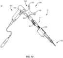
- shaft 70is attached with end 18 such that inner shaft 56, wheel 84, screw 64 freely slide, translate, rotate and/or float within channel 52. Inner shaft 56 retains screw 64 and wheel 84 with sleeve 14. In some embodiments, shaft 70 is welded with outer sleeve 14. In some embodiments, shaft 70 is configured to facilitate connection of driver 12 with a surgical instrument, such as, for example, an actuator/drill 250, as shown in FIG. 12 . In some embodiments, shaft 70 includes quick connect surfaces or keyed geometry, such as, for example, triangle, hex, square or hexalobe to facilitate connection with actuator 250.
- End 20 of outer sleeve 14includes a distal tip, such as, for example, drive 22, as shown in FIG. 4 .
- Drive 22is integrally connected or monolithically formed with outer sleeve 14. This configuration facilitates control of tolerances to optimize accuracy of the connection of outer sleeve 14 with bone fastener 100.
- Drive 22is engageable with a spinal implant, such as, for example, bone fastener 100.
- a spinal implantsuch as, for example, bone fastener 100.
- drive 22fits with and is engageable with a mating surface, such as, for example, a socket 110 of bone fastener 100.
- Rotation of outer sleeve 14simultaneously rotates drive 22 to drive, torque, insert or otherwise connect bone fastener 100 with tissue, as described herein.
- drive 22includes a hexalobe geometry for a mating engagement with a correspondingly shaped socket 110.
- drive 22can alternatively include a cruciform, phillips, square, hexagonal, polygonal, star cross sectional configuration for disposal of a correspondingly shaped socket 110.
- Outer sleeve 14includes an extension 30 and an extension 32.
- Extensions 30, 32include a wall 34 having a surface 36.
- Surface 36is connectable with an implant support, such as, for example, extender tab 152, as described herein.
- Surface 36defines a mating groove, such as, for example, a pocket 38 configured for engagement with extender tab 152, as described herein.
- Surface 36is configured to resist and/or prevent disengagement of extender tab 152 from pocket 38, as described herein.
- Extensions 30, 32include a wall 40 having a surface 42.
- Surface 42is connectable with extender tab 152a, as described herein.
- Surface 42defines a mating groove, such as, for example, a pocket 44 configured for engagement with extender tab 152a, as described herein.
- Surface 42is configured to resist and/or prevent disengagement of extender tab 152a from pocket 44, as described herein.
- Pockets 38, 44are configured for engagement with extender tabs 152, 152a, as shown in FIGS. 5 and 8 . Disposal of extender tabs 152, 152a with pockets 38, 44 is configured to resist and/or prevent extender tabs 152, 152a from increasing diameter D1 when engaged with driver 12. In some embodiments, pockets 38, 44 are disposed parallel to axis a. In some embodiments, pockets 38, 44 are disposed at alternate orientations relative to axis a, such as, for example, at transverse, perpendicular and/or other angular orientations such as acute or obtuse, and/or may be offset or staggered.
- Bone fastener 100includes receiver 102.
- Receiver 102extends along axis a when connected with outer sleeve 14.
- Receiver 102includes a pair of spaced apart arms 104, 106 that define an implant cavity configured for disposal of a component of a spinal construct, such as, for example, a spinal rod (not shown).
- Receiver 106includes socket 110 configured for engagement with drive 22, as described herein.
- Receiver 102includes an inner surface having a thread form located adjacent arm 104 and a thread form located adjacent arm 106. The thread forms of arms 104, 106 are configured for engagement with thread form 89 to retain bone fastener 100 with driver 12, as described herein.
- Bone fastener 100includes a threaded shaft 116. Shaft 116 is configured to penetrate tissue, such as, for example, bone.
- Arm 104includes a break away tab 120 that is frangibly connected to arm 104 such that manipulation of tab 120 relative to arm 104 can fracture and separate tab 120 from arm 104 at a predetermined force and/or torque limit, as described herein.
- Arm 106includes a break away tab 130 that is frangibly connected to arm 106 such that manipulation of tab 130 relative to arm 106 can fracture and separate tab 130 from arm 106 at a predetermined force and/or torque limit, as described herein.
- force and/or torqueis applied to tabs 120, 130 and resistance increases, for example, the predetermined torque and force limit is approached.
- tabs 120, 130can fracture and separate at a predetermined force or torque limit, which may be in a range of approximately 2 Newton meters (N-m) to 8 N-m.
- a predetermined force or torque limitwhich may be in a range of approximately 2 Newton meters (N-m) to 8 N-m.
- tabs 120, 130 and arms 104, 106may have the same or alternate cross section configurations, may be fabricated from a homogenous material or heterogeneously fabricated from different materials, and/or alternately formed of a material having a greater degree, characteristic or attribute of plastic deformability, frangible property and/or break away quality to facilitate fracture and separation of tabs 120, 130.
- a bone fastener assembly 150includes extender tabs 152, 152a connected with bone fastener 100.
- Extender tabs 152, 152aextend between a proximal end 172 and a distal end 174.
- Proximal end 172includes spring tips 176, 178, as shown in FIG. 8 .
- Spring tips 176, 178are aligned and disposable with pockets 38, 44.
- Surfaces 36, 42are configured to resist and/or prevent disengagement of spring tips 176, 178, as described herein.
- Distal ends 174are configured for slidable disposal of a portion of bone fastener 100, such as, for example, tabs 120, 130.
- tabs 120, 130are configured to releasably fix extender tabs 152, 152a with bone fastener 100 for connection with outer sleeve 14.
- bone fastener assembly 150is connected with driver 12, as described herein, and drive 22 is oriented for engagement with socket 110.
- Drive 22is engaged with socket 110 and screw 64 is disposed with inner shaft 56 and assembled with outer sleeve 14 for axial translation relative to outer sleeve 14 and along inner shaft 56 between a non-locking configuration, as shown in FIG. 4 , and a locking configuration, as shown in FIG. 5 , with a spinal implant, such as, for example, bone fastener 100.
- screw 64is freely translatable relative to inner shaft 56 within an opening 51 of channel 52, in the direction shown by arrows A in FIG. 4 , and rotatable relative to outer sleeve 14. This configuration allows drive 22 to engage socket 110 prior to fixation of screw 64 with bone fastener 100.
- thread form 89is aligned with the thread forms of arms 104, 106 for engagement therebetween to retain bone fastener 100 with driver 12.
- Screw 64is keyed with the double D cross section of end 62 for simultaneous rotation with inner shaft 56 and wheel 84. Wheel 84 is manipulated for rotation such that inner shaft 56 rotates screw 64 relative to and independent of outer sleeve 14.
- Thread form 89engages the thread forms of arms 104, 106 and screw 64 axially translates into receiver 102 and relative to inner shaft 56. The threaded engagement of screw 64 and receiver 102 pulls and/or draws bone fastener 100 into the locking configuration with driver 12 for releasable fixation therebetween.
- Screw 64remains releasably fixed with receiver 102, independent of outer sleeve 14 rotation and/or engagement or friction with components of spinal implant system 10 as described herein, to resist and/or prevent disengagement or unthreading of screw 64 from receiver 102.
- driver 12includes a navigation component 300, as shown in FIGS. 12 and 13 (embodiments do not form part of the invention but represent background art that is useful for understanding the invention).
- Driver 12is configured for disposal adjacent a surgical site such that navigation component 300 is oriented relative to a sensor array 302 to facilitate communication between navigation component 300 and sensor array 302 during a surgical procedure, as described herein.
- Navigation component 300is configured to generate a signal representative of a position of bone fastener 100 relative to driver 12 and/or tissue.
- the image guidemay include human readable visual indicia, human readable tactile indicia, human readable audible indicia, one or more components having markers for identification under x-ray, fluoroscopy, CT or other imaging techniques, at least one light emitting diode, a wireless component, a wired component, a near field communication component and/or one or more components that generate acoustic signals, magnetic signals, electromagnetic signals and/or radiologic signals.
- navigation component 300is connected with shaft 70 or outer sleeve 14 via an integral connection, friction fit, pressure fit, interlocking engagement, mating engagement, dovetail connection, clips, barbs, tongue in groove, threaded, magnetic, key/keyslot and/or drill chuck.
- Navigation component 300includes an emitter array 304 according to an example (example does not form part of the invention but represent background art that is useful for understanding the invention).
- Emitter array 304is configured for generating a signal to sensor array 302 of a surgical navigation system 306, as shown in FIG. 13 and described herein.
- the signal generated by emitter array 304represents a position of bone fastener 100 relative to driver 12 and relative to tissue, such as, for example, bone.
- the signal generated by emitter array 304represents a three dimensional position of bone fastener 100 relative to tissue.
- sensor array 302receives signals from emitter array 304 to provide a three-dimensional spatial position and/or a trajectory of bone fastener 100 relative to driver 12 and/or tissue (embodiments do not form part of the invention but represent background art that is useful for understanding the invention).
- Emitter array 304communicates with a processor of computer 308 of navigation system 306 to generate data for display of an image on monitor 310, as described herein.
- sensor array 302receives signals from emitter array 304 to provide a visual representation of a position of bone fastener 100 relative to driver 12 and/or tissue.
- Surgical navigation system 306is configured for acquiring and displaying medical imaging, such as, for example, x-ray images appropriate for a given surgical procedure. In some embodiments, pre-acquired images of a patient are collected.
- surgical navigation system 306can include an O-arm ® imaging device 310 sold by Medtronic Navigation, Inc. having a place of business in Louisville, Colo., USA. Imaging device 310 may have a generally annular gantry housing that encloses an image capturing portion 312.
- navigation system 306comprises an image capturing portion 314 that may include an x-ray source or emission portion and an x-ray receiving or image receiving portion located generally or as practically possible 180 degrees from each other and mounted on a rotor (not shown) relative to a track of image capturing portion 314 (embodiments do not form part of the invention but represent background art that is useful for understanding the invention).
- Image capturing portion 314can be operable to rotate 360 degrees during image acquisition.
- Image capturing portion 314may rotate around a central point or axis, allowing image data of the patient to be acquired from multiple directions or in multiple planes.
- surgical navigation system 306can include C-arm fluoroscopic imaging systems, which can generate three-dimensional views of a patient.
- the position of image capturing portion 314can be precisely known relative to any other portion of an imaging device of navigation system 306 (embodiments do not form part of the invention but represent background art that is useful for understanding the invention).
- a precise knowledge of the position of image capturing portion 314can be used in conjunction with a tracking system 316 to determine the position of image capturing portion 314 and the image data relative to the patient (embodiments do not form part of the invention but represent background art that is useful for understanding the invention).
- tracking system 316can include various portions that are associated or included with surgical navigation system 306 (examples do not form part of the invention but represent background art that is useful for understanding the invention).
- tracking system 316can also include a plurality of types of tracking systems, such as, for example, an optical tracking system that includes an optical localizer, such as, for example, sensor array 302 and/or an EM tracking system that can include an EM localizer.
- various tracking devicescan be tracked with tracking system 316 and the information can be used by surgical navigation system 306 to allow for a display of a position of an item, such as, for example, a patient tracking device, an imaging device tracking device 318, and an instrument tracking device, such as, for example, emitter array 304, to allow selected portions to be tracked relative to one another with the appropriate tracking system (examples do not form part of the invention but represent background art that is useful for understanding the invention).
- the EM tracking systemcan include the STEALTHSTATION ® AXIEM TM Navigation System, sold by Medtronic Navigation, Inc. having a place of business in Louisville, Colo (embodiments do not form part of the invention but represent background art that is useful for understanding the invention).
- Fluoroscopic images takenare transmitted a computer 314 where they may be forwarded to computer 308.
- Image transfermay be performed over a standard video connection or a digital link including wired and wireless.
- Computer 308provides the ability to display, via monitor 310, as well as save, digitally manipulate, or print a hard copy of the received images. In some embodiments, images may also be displayed to the surgeon through a heads-up display.
- surgical navigation system 306provides for real-time tracking of the position of bone fastener 100 relative to driver 12 and/or tissue can be tracked (embodiments do not form part of the invention but represent background art that is useful for understanding the invention).
- Sensor array 302is located in such a manner to provide a clear line of sight with emitter array 304, as described herein.
- fiducial markers 330 of emitter array 304communicate with sensor array 302 via infrared technology.
- Sensor array 302is coupled to computer 308, which may be programmed with software modules that analyze signals transmitted by sensor array 302 to determine the position of each object in a detector space.
- Driver 12is configured for use with an end effector 200 of a robotic arm R.
- End effector 200includes a surface 202 that defines a cavity, such as, for example, a channel 204.
- Channel 204is configured for passage of bone fastener assembly 150 and disposal of driver 12.
- Robotic arm Rincludes position sensors (not shown), similar to those referenced herein, which measure, sample, capture and/or identify positional data points of end effector 200 in three dimensional space for a guide-wireless insertion of bone fasteners 100 with selected vertebral levels.
- the position sensors of robotic arm Rare employed in connection with surgical navigation system 306 to measure, sample, capture and/or identify positional data points of end effector 200 in connection with surgical treatment, as described herein.
- the position sensorsare mounted with robotic arm R and calibrated to measure positional data points of end effector 200 in three dimensional space, which are communicated to computer 308.
- spinal implant system 10In assembly, operation and use, spinal implant system 10, similar to the systems described herein, is employed with a surgical procedure (surgical procedure or treatment do not form part of the invention), such as, for example, a treatment of an applicable condition or injury of an affected section of a spinal column and adjacent areas within a body.
- a surgical proceduresurgical procedure or treatment do not form part of the invention
- spinal implant system 10can be delivered or utilized as a pre- assembled device or can be assembled in situ.
- Spinal implant system 10may be completely or partially revised, removed or replaced.
- spinal implant system 10can be used in any existing surgical method or technique (not forming part of the invention but represent background art that is useful for understanding the invention) including open surgery, mini-open surgery, minimally invasive surgery and percutaneous surgical implantation, whereby the vertebrae is accessed through a mini-incision, or sleeve that provides a protected passageway to the area. Once access to the surgical site is obtained, the particular surgical procedure can be performed for treating the spine disorder (surgical procedure does not form part of the invention).
- a cutting instrument(not shown) creates a surgical pathway for implantation of components of spinal implant system 10 (surgical method does not form part of the invention).
- a preparation instrument(not shown) can be employed to prepare tissue surfaces of the vertebrae as well as for aspiration and irrigation of a surgical region (preparation instrument does not form part of the invention).
- Bone fastener assembly 150is connected with driver 12, as described herein.
- Drive 22is engaged with socket 110 and screw 64 is disposed in a non-locking configuration, as described herein, such that screw 64 is freely translatable relative to inner shaft 56 within an opening 51 of channel 52 and rotatable relative to outer sleeve 14.
- wheel 84is manipulated for rotation such that inner shaft 56 rotates screw 64 relative to and independent of outer sleeve 14, as described herein. Threaded engagement of screw 64 and receiver 102 pulls and/or draws bone fastener 100 into the locking configuration with driver 12 for releasable fixation therebetween.
- Driver 12connected with bone fastener assembly 150, is oriented for disposal with end effector 200 of robotic arm R (not forming part of the invention), as described herein.
- the assembly of driver 12/bone fastener assembly 150are disposed with channel 204 for implantation of bone fasteners 100 with vertebrae employing robotic arm R and/or surgical navigation system 306, as described herein.
- Actuator 250is connected with shaft 70 and drive 22 engages bone fastener 100, as described herein, and outer sleeve 14 is rotated to drive, torque, insert or otherwise connect bone fastener 100 with adjacent tissue (surgical method not forming part of the invention).
- Screw 64remains releasably fixed with receiver 102, independent of outer sleeve 14 rotation and/or engagement or friction with end effector 200 to resist and/or prevent disengagement or unthreading of screw 64 from receiver 102.
- driver 12is manipulated to deliver one or more bone fasteners 100 to a surgical site including vertebrae.
- Sensor array 302receives signals from navigation component 300 to provide a three-dimensional spatial position and/or a trajectory of the assembly of driver 12/bone fastener assembly 150, which may be disposed with end effector 200, relative to vertebrae and/or components of spinal implant system 10 for display on monitor 310.
- spinal implant system 10Upon completion of a procedure, as described herein, the surgical instruments, assemblies and non-implanted components of spinal implant system 10 are removed and the incision(s) are closed (surgical method not forming part of the invention).
- One or more of the components of spinal implant system 10can be made of radiolucent materials such as polymers. Radiomarkers may be included for identification under x-ray, fluoroscopy, CT or other imaging techniques.
- spinal implant system 10may include one or a plurality of spinal rods, plates, connectors and/or bone fasteners for use with a single vertebral level or a plurality of vertebral levels.
- one or more bone fastenersmay be engaged with tissue in various orientations, such as, for example, series, parallel, offset, staggered and/or alternate vertebral levels.
- the bone fastenersmay comprise multi-axial screws, sagittal adjusting screws, pedicle screws, mono-axial screws, uni-planar screws, facet screws, fixed screws, tissue penetrating screws, conventional screws, expanding screws, wedges, anchors, buttons, clips, snaps, friction fittings, compressive fittings, expanding rivets, staples, nails, adhesives, posts, fixation plates and/or posts.
- spinal implant system 10includes an agent, which may be disposed, packed, coated or layered within, on or about the components and/or surfaces of spinal implant system 10 (embodiment does not form part of the invention but represent background art that is useful for understanding the invention).
- the agentmay include bone growth promoting material, such as, for example, bone graft to enhance fixation of the components and/or surfaces of spinal implant system 10 with vertebrae (embodiments do not form part of the invention but represent background art that is useful for understanding the invention).
- the agentmay include one or a plurality of therapeutic agents and/or pharmacological agents for release, including sustained release, to treat, for example, pain, inflammation and degeneration (therapeutic method not forming part of the invention).
- spinal implant system 10similar to the systems described herein, includes a driver 412, similar to driver 12 described herein.
- Driver 412is configured for connection with a multi- axial screw (MAS) 500.
- MASmulti- axial screw
- Driver 412can be employed with end effector 200 and/or surgical navigation system 306, as described herein, for guide-wireless insertion of MAS 500 with tissue, similar to that described herein.
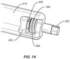
- Driver 412includes an outer sleeve 414.
- Outer sleeve 414extends between a proximal end 418 and a distal end 420.
- Outer sleeve 414includes a continuous and non-interrupted outer surface 450 that extends between ends 418, 420.
- Surface 450defines an interior channel 452.
- Channel 452is configured for disposal of an inner shaft 456, similar to inner shaft 56, and a screw 464, similar to screw 64 described herein.
- Outer sleeve 414includes a collar body 416, similar to collar body 16 described herein, to facilitate disposal and access to a thumb wheel 484, similar to wheel 84 described herein.
- Inner shaft 456is engageable with wheel 484 for rotation of inner shaft 456 and screw 464, similar to that described herein.
- Screw 464includes an outer surface having a thread form 489 configured for engagement with thread forms of arms 504, 506 of MAS 500 to pull and/or draw MAS 500 into engagement with driver 412, as described herein.
- Inner shaft 456 and screw 464are configured for movement relative to outer sleeve 414.
- a shaft 470similar to shaft 70 described herein, is inserted and attached with outer sleeve 414 to assemble and retain inner shaft 456, wheel 484, screw 464 within channel 452 in a relatively movable configuration with outer sleeve 414, similar to that described herein.
- End 420 of outer sleeve 414includes a distal tip, such as, for example, drive 422, similar to drive 22 described herein.
- Drive 422is integrally connected or monolithically formed with outer sleeve 414 and fits with and is engageable with a mating surface, such as, for example, a socket (not shown) of MAS 500, similar to that described herein.
- Rotation of outer sleeve 414simultaneously rotates drive 422 to drive, torque, insert or otherwise connect MAS 500 with tissue, similar to that described herein.
- drive 422is oriented for engagement with the socket of MAS 500.
- Drive 422is engaged with the socket of MAS 500 and screw 464 is disposed with inner shaft 456 and assembled with outer sleeve 414 for axial translation relative to outer sleeve 414 and along inner shaft 456 between a non-locking configuration and a locking configuration, with MAS 500, similar to that described herein.
- screw 464is freely translatable relative to inner shaft 456 and rotatable relative to outer sleeve 414.
- thread form 489is aligned with the thread forms of arms 504, 506 to retain MAS 500 with driver 412.
- Wheel 484is manipulated for rotation such that inner shaft 456 rotates screw 464 relative to and independent of outer sleeve 414.
- Thread form 489engages the thread forms of arms 504, 506 and screw 464 axially translates into the receiver of MAS 500 and relative to inner shaft 456.
- the threaded engagement of screw 464 and the receiver of MAS 500pulls and/or draws MAS 500 into the locking configuration with driver 412 for releasable fixation therebetween.
- Drive 422is connected with outer sleeve 414, as described herein, and outer sleeve 414 is rotated to drive, torque, insert or otherwise connect MAS 500 with adjacent tissue (surgical method does not form part of the invention).
- Screw 464remains releasably fixed with the receiver of MAS 500, independent of outer sleeve 414 rotation and/or engagement or friction with components of spinal implant system 10, as described herein, to resist and/or prevent disengagement or unthreading of screw 464 from the receiver of MAS 500.
Landscapes
- Health & Medical Sciences (AREA)
- Surgery (AREA)
- Life Sciences & Earth Sciences (AREA)
- Orthopedic Medicine & Surgery (AREA)
- Neurology (AREA)
- Engineering & Computer Science (AREA)
- Medical Informatics (AREA)
- Heart & Thoracic Surgery (AREA)
- Biomedical Technology (AREA)
- Molecular Biology (AREA)
- Animal Behavior & Ethology (AREA)
- General Health & Medical Sciences (AREA)
- Public Health (AREA)
- Veterinary Medicine (AREA)
- Nuclear Medicine, Radiotherapy & Molecular Imaging (AREA)
- Robotics (AREA)
- Surgical Instruments (AREA)
Description
- The invention relates to a surgical instrument according to the preamble of claim 1. Accordingly, the invention generally relates to a surgical instrument and a surgical system.
- Spinal pathologies and disorders such as scoliosis and other curvature abnormalities, kyphosis, degenerative disc disease, disc herniation, osteoporosis, spondylolisthesis, stenosis, tumor and fracture may result from factors including trauma, disease and degenerative conditions caused by injury and aging. Spinal disorders typically result in symptoms including deformity, pain, nerve damage, and partial or complete loss of mobility.
- Non-surgical treatments, such as medication, rehabilitation and exercise can be effective, however, may fail to relieve the symptoms associated with these disorders. Surgical treatment of these spinal disorders includes correction, fusion, fixation, discectomy, laminectomy and implantable prosthetics. As part of these surgical treatments, spinal constructs such as vertebral rods are often used to provide stability to a treated region. Rods redirect stresses away from a damaged or defective region while healing takes place to restore proper alignment and generally support vertebral members. During surgical treatment, one or more rods and bone fasteners can be delivered to a surgical site. The rods may be attached via the fasteners to the exterior of two or more vertebral members. Surgical treatment may employ surgical instruments and implants that are manipulated for engagement with vertebrae to position and align one or more vertebrae. This disclosure describes an improvement over these prior technologies. A surgical instrument of the initially-mentioned type is known, e.g., from
US 2015/250512 A . - The invention provides a surgical instrument according to claim 1.
- Further embodiments are described in the dependent claims.
- In one embodiment, a surgical system is provided.
- The present disclosure will become more readily apparent from the specific description accompanied by the following drawings, in which:
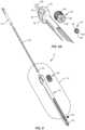
FIG. 1 is a perspective view of components of one embodiment of a surgical system in accordance with the principles of the present disclosure;FIG. 2 is a cross section view of the components shown inFIG. 1 .FIG. 3 is a perspective view of components of the system shown inFIG. 1 ;FIG. 4 is a break away view of components of the system shown inFIG. 1 ;FIG. 5 is a perspective view of components of one embodiment of a surgical system in accordance with the principles of the present disclosure;FIG. 6 is a perspective view of components of the system shown inFIG. 5 with parts separated;FIG. 7 is a break away view of components of the system shown inFIG. 6 ;FIG. 8 is a break away view of components of the system shown inFIG. 5 ;FIG. 9 is a perspective view of components of the system shown inFIG. 5 with parts separated;FIG. 9A is an enlarged view of detail A shown inFIG. 9 ;FIG. 10 is a perspective view of components of one embodiment of a surgical system in accordance with the principles of the present disclosure;FIG. 11 is a perspective view of the components of the system shown inFIG. 10 ;FIG. 12 is a perspective view of components of one embodiment of a surgical system in accordance with the principles of the present disclosure;FIG. 13 is a perspective view of components one embodiment of a surgical system in accordance with the principles of the present disclosure;FIG. 14 is a break away view of components of one embodiment of a surgical system in accordance with the principles of the present disclosure; andFIG. 15 is a perspective view of components of one embodiment of a surgical system in accordance with the principles of the present disclosure.- The exemplary embodiments of the surgical instrument and the surgical system disclosed are discussed in terms of medical devices for the treatment of musculoskeletal disorders and more particularly, in terms of a spinal implant system for treating a spine. In some embodiments, the systems of the present disclosure comprise medical devices including surgical instruments and implants that are employed with a surgical treatment, as described herein, for example, with a cervical, thoracic, lumbar and/or sacral region of a spine.
- In some embodiments, the present surgical system comprises a surgical instrument that comprises a screw driver that can be employed with bone fasteners and one or more implant supports, such as, for example, an extender, for treating a spine. In some embodiments, the present surgical system includes a surgical instrument that can easily connect and disconnect from a bone fastener. In some embodiments, an extender can be connected in alignment with the surgical instrument to facilitate manipulation. In some embodiments, the present surgical system includes a surgical instrument that can be employed with an end effector of a robotic arm to facilitate implant with the robotic arm (embodiments do not form part of the invention but represent background art that is useful for understanding the invention). In some embodiments, the surgical instrument is guided through the end effector for a guide-wireless screw insertion (embodiments do not form part of the invention but represent background art that is useful for understanding the invention). In some embodiments, the surgical instrument comprises a robot screw driver employed with robotic and/or navigation guidance, which may include an image guide (embodiments do not form part of the invention but represent background art that is useful for understanding the invention).
- In some embodiments, the present surgical system includes a screw driver having an outer shaft and a drive tip that engages a bone fastener. In some embodiments, the outer shaft and the drive tip are of one piece construction. In some embodiments, the one piece construction allows tolerances to be controlled tightly for improved accuracy of trajectory during implant insertion. In some embodiments, the drive tip includes a Torx configuration. In some embodiments, the present surgical system includes a screw driver having an internal retention mechanism. In some embodiments, the retention mechanism is fixed with a receiver of a bone fastener to resist and/or prevent disengagement of the retention mechanism from the receiver, for example, due to connection or friction with the end effector or tissue.
- In some embodiments, the present surgical system includes a screw driver for use with robotic surgery. In some embodiments, the screw driver can be employed with fixed-axis screws (FAS), uni-axial screws (UAS), sagittal adjusting screws (SAS), transverse sagittal adjusting screws (TSAS) and multi-axial screws (MAS) screws, and allows the screws to be driven through a robotic end effector. In some embodiments, the screw driver includes a one piece outer sleeve having a tip. In some embodiments, the screw driver includes an internal retaining device that prevents accidental disengagement and/or unthreading.
- In some embodiments, the present surgical system includes a screw driver including an outer shaft or sleeve having an outside diameter that is slightly larger than a screw spin diameter of a bone screw. This configuration allows the bone screw and the screw driver to pass through the end effector. In some embodiments, the screw driver includes a thumb wheel that is connected to a retention screw that threads into the bone screw. In some embodiments, the present surgical system includes tab extenders connected to the screw driver and prevented from extending outside the outside diameter of the screw driver by engaging undercuts of the screw driver. This configuration prevents an interference or hang-up if the bone screw needs to be removed through the end effector.
- In some embodiments, the present surgical system includes a screw driver that is employed with a method of assembling components of the present system, which includes the step of connecting a bone screw to the screw driver (embodiments concerning the method of assembling components do not form part of the invention bet represent background art that is useful for understanding the invention). In some embodiments, the method includes the step of inserting a drive tip of the screw driver into a drive socket of a receiver of the bone screw while aligning tab extenders in mating grooves of the screw driver. In some embodiments, the method includes the step of rotating a thumb wheel actuator of the screw driver to tighten and pull the bone screw tight against the screw driver. In some embodiments, the method includes the step of inserting the retention screw and thumb wheel laterally with an outer shaft/sleeve of the screw driver. In some embodiments, the method includes sliding an inner shaft of the screw driver from a rear orientation. In some embodiments, the retention screw, thumb wheel and inner shaft include mating surfaces having a double D shape to transmit torque. In some embodiments, the method includes internal parts that are retained by inserting a quick connect shaft from a rear orientation and welding the quick connect shaft to the outer shaft.
- In some embodiments, the present surgical system includes a screw driver that includes a quick connect shaft, an inner shaft, a thumb wheel, an outer driver shaft and a retention screw. The inner shaft, thumb wheel and retention screw include double D or hex shape mating surfaces. In some embodiments, the screw driver includes cleaning slots for flushing and/or cleaning. In some embodiments, the thumb wheel, retention screw and inner shaft freely float within the assembly. In some embodiments, the retention screw can freely translate axially relative to the inner shaft or up and down along the inner shaft. In some embodiments, the retention screw and the thumb wheel are keyed to a double-D configuration of the inner shaft. In some embodiments, the retention screw is axially translatable relative to the inner shaft between a first position, for example, a non-locking position prior to tightening, and a second position, for example, a locking position after tightening. In some embodiments, this configuration allows the drive tip to engage the bone screw prior to rotating the thumb wheel for tightening the screw driver to the bone screw.
- In some embodiments, the surgical system includes an implant support, such as, for example, a collar and extender tabs. In some embodiments, the surgical system is employed with a method for treating spinal trauma and/or deformity disorders (the method does not form part of the invention but represent background art that is useful for understanding the invention). In some embodiments, the surgical system is employed with a method for treating spinal trauma and/or deformity disorders with a minimally invasive surgical technique (the method does not form part of the invention but represent background art that is useful for understanding the invention).
- In some embodiments, the surgical system includes extender tabs. In some embodiments, the extender tabs are configured for aligning an implant, such as, for example, a bone fastener, with various instruments and providing an access path for set screws and rods. In some embodiments, the extender tabs are connectable with a SAS. In some embodiments, the surgical system facilitates sagittal correction and/or manipulation when a spinal implant, such as, for example, a spinal rod is disposed with a receiver. In some embodiments, the extender tabs are connectable with a TSAS. In some embodiments, the surgical system includes a receiver that is configured to accommodate transverse and sagittal anatomical differences.
- In some embodiments, the surgical system of the present disclosure may be employed to treat spinal disorders such as, for example, degenerative disc disease, disc herniation, osteoporosis, spondylolisthesis, stenosis, scoliosis and other curvature abnormalities, kyphosis, tumor and fractures. In some embodiments, the surgical system of the present disclosure may be employed with other osteal and bone related applications, including those associated with diagnostics and therapeutics. In some embodiments, the disclosed surgical system may be alternatively employed in a surgical treatment with a patient in a prone or supine position, and/or employ various surgical approaches to the spine, including anterior, posterior, posterior mid-line, direct lateral, postero-lateral, and/or antero-lateral approaches, and in other body regions (surgical treatment does not form part of the invention but represent background art that is useful for understanding the invention). The surgical system of the present disclosure may also be alternatively employed with procedures for treating the lumbar, cervical, thoracic, sacral and pelvic regions of a spinal column (procedures do not form part of the invention but represent background art that is useful for understanding the invention). The surgical system of the present disclosure may also be used on animals, bone models and other non-living substrates, such as, for example, in training, testing and demonstration.
- The surgical system of the present disclosure may be understood more readily by reference to the following detailed description of the embodiments taken in connection with the accompanying drawing figures, which form a part of this disclosure.
- The following discussion includes a description of a surgical system including a surgical instrument and related components of employing the surgical system in accordance with the principles of the present disclosure. Alternate embodiments are also disclosed. Reference is made in detail to the exemplary embodiments of the present disclosure, which are illustrated in the accompanying figures. Turning to
FIGS. 1-13 , there are illustrated components of a surgical system, such as, for example, aspinal implant system 10. - The components of
spinal implant system 10 can be fabricated from biologically acceptable materials suitable for medical applications, including metals, synthetic polymers, ceramics and bone material and/or their composites. For example, the components of spinal implant system 10, individually or collectively, can be fabricated from materials such as stainless steel alloys, aluminum, commercially pure titanium, titanium alloys, Grade 5 titanium, super-elastic titanium alloys, cobalt-chrome alloys, superelastic metallic alloys (e.g., Nitinol, super elasto-plastic metals, such as GUM METAL®), ceramics and composites thereof such as calcium phosphate (e.g., SKELITE™), thermoplastics such as polyaryletherketone (PAEK) including polyetheretherketone (PEEK), polyetherketoneketone (PEKK) and polyetherketone (PEK), carbon-PEEK composites, PEEK-BaSO4 polymeric rubbers, polyethylene terephthalate (PET), fabric, silicone, polyurethane, silicone-polyurethane copolymers, polymeric rubbers, polyolefin rubbers, hydrogels, semi-rigid and rigid materials, elastomers, rubbers, thermoplastic elastomers, thermoset elastomers, elastomeric composites, rigid polymers including polyphenylene, polyamide, polyimide, polyetherimide, polyethylene, epoxy, bone material including autograft, allograft, xenograft or transgenic cortical and/or corticocancellous bone, and tissue growth or differentiation factors, partially resorbable materials, such as, for example, composites of metals and calcium-based ceramics, composites of PEEK and calcium based ceramics, composites of PEEK with resorbable polymers, totally resorbable materials, such as, for example, calcium based ceramics such as calcium phosphate, tri-calcium phosphate (TCP), hydroxyapatite (HA)-TCP, calcium sulfate, or other resorbable polymers such as polyaetide, polyglycolide, polytyrosine carbonate, polycaroplaetohe and their combinations. - Various components of
spinal implant system 10 may have material composites, including the above materials, to achieve various desired characteristics such as strength, rigidity, elasticity, compliance, biomechanical performance, durability and radiolucency or imaging preference. The components ofspinal implant system 10, individually or collectively, may also be fabricated from a heterogeneous material such as a combination of two or more of the above-described materials. The components ofspinal implant system 10 may be monolithically formed, integrally connected or include fastening elements and/or instruments, as described herein. Spinal implant system 10 is employed, for example, with a fully open surgical procedure, a minimally invasive procedure including percutaneous techniques, and mini-open surgical techniques to deliver and introduce instrumentation and/or a spinal implant, such as, for example, a bone fastener, at a surgical site of a patient, which includes, for example, a spine. In some embodiments, the spinal implant can include one or more components of one or more spinal constructs, such as, for example, interbody devices, interbody cages, bone fasteners, spinal rods, tethers, connectors, plates and/or bone graft, and can be employed with various surgical procedures including surgical treatment of a cervical, thoracic, lumbar and/or sacral region of a spine.Spinal implant system 10 includes a surgical instrument, such as, for example, adriver 12.Driver 12 can be employed with an end effector 200 (FIG. 10 ) of a robotic arm R (FIG. 13 ) to facilitate implant with roboticarm R. Driver 12 is guided throughend effector 200 for guide-wireless insertion of a spinal implant, such as, for example, abone fastener 100, as described herein (example does not form part of the invention but represent background art that is useful for understanding the invention).Driver 12 includes a member, such as, for example, an outertubular sleeve 14.Outer sleeve 14 extends between aproximal end 18 and adistal end 20.Outer sleeve 14 defines a longitudinal axis a. In some embodiments,outer sleeve 14 may have various configurations including, for example, round, oval, polygonal, irregular, consistent, variable, uniform and non-uniform.Outer sleeve 14 includes a diameter D1. In some embodiments, diameter D1 is slightly larger than a screw spin diameter D2 ofbone fastener 100. This configuration allowsbone fastener 100 anddriver 12 to pass throughend effector 200 of the robotic arm, as described herein.Outer sleeve 14 includes asurface 50 that defines achannel 52.Channel 52 is configured for disposal of a member, such as, for example, aninner shaft 56 and an engagement element, such as, for example, ascrew 64, as described herein.Outer sleeve 14 includes acollar body 16 having asurface 80.Surface 80 defines acavity 82.Body 16 includes bifurcatedarms 92 disposed aboutcavity 82 to facilitate disposal and access to an actuator, such as, for example, athumb wheel 84 therein.Body 16 includesopening 94 disposed atend 18.Opening 94 is in communication withcavity 82 and in alignment withchannel 52 to facilitate insertion ofinner shaft 56 intoend 18, throughwheel 84 and intochannel 52 for assembly, as described herein.Wheel 84 is configured to actuate rotation ofinner shaft 56 andscrew 64, as described herein.Wheel 84 includes asurface 86 that defines acavity 88.Cavity 88 is configured for disposal of a correspondingly shaped portion ofinner shaft 56, as shown inFIGS. 9 and 9A .Inner shaft 56 extends between anend 60 and anend 62.End 60 is engageable withwheel 84 for rotation ofinner shaft 56 andscrew 64, as described herein.Surface 86 engagesend 60 in an interference fit to facilitate simultaneous rotation ofwheel 84 andinner shaft 56. In some embodiments,surface 86 defines a double-D cross section for a mating engagement with correspondingly shapedend 60 ofinner shaft 56. In some embodiments,cavity 88 includes various configurations, such as, for example, hexalobe, cruciform, phillips, square, hexagonal, polygonal, star cross sectional configuration for a mating engagement with correspondingly shaped portion ofinner shaft 56. In some embodiments,wheel 84 includes asurface 90 configured to facilitate gripping ofwheel 84, such as, for example a knurled surface.Screw 64 includes aninner surface 66.Surface 66 defines acavity 68 configured for disposal of a correspondingly shaped portion ofend 62 ofinner shaft 56.Surface 66 engagesinner shaft 56 in an interference fit to facilitate simultaneous rotation ofinner shaft 56 andscrew 64, as described herein. In some embodiments,surface 66 defines a double-D cross section for a mating engagement with correspondingly shapedend 62. In some embodiments,cavity 68 includes various configurations, such as, for example, hexalobe, cruciform, phillips, square, hexagonal, polygonal, star cross sectional configuration for a mating engagement with a correspondinglyshaped end 62.Screw 64 includes an outer surface having athread form 89.Thread form 89 is configured for engagement with a mating surface, such as, for example, thread forms ofarms bone fastener 100 to pull and or drawbone fastener 100 into engagement withdriver 12, as described herein.Inner shaft 56 and screw 64 are configured for movement relative toouter sleeve 14.Screw 64 is inserted laterally intochannel 52.Wheel 84 is inserted laterally intocavity 82. Withwheel 84 and screw 64 provisionally assembled withouter sleeve 14,inner shaft 56 is inserted fromend 18, throughopening 94, throughcavity 88 and intochannel 52 such thatend 62 engages and passes throughscrew 64.Screw 64 is disposed withinner shaft 56 andwheel 84 is disposed withcollar body 16, withinchannel 52, for assembly of the components ofdriver 12. Ashaft 70 is inserted and attached withend 18 to assemble and retaininner shaft 56,wheel 84, screw 64 withinchannel 52 in a relatively movable configuration withouter sleeve 14, as described herein. In some embodiments,shaft 70 is attached withend 18 such thatinner shaft 56,wheel 84, screw 64 freely slide, translate, rotate and/or float withinchannel 52.Inner shaft 56 retainsscrew 64 andwheel 84 withsleeve 14. In some embodiments,shaft 70 is welded withouter sleeve 14. In some embodiments,shaft 70 is configured to facilitate connection ofdriver 12 with a surgical instrument, such as, for example, an actuator/drill 250, as shown inFIG. 12 . In some embodiments,shaft 70 includes quick connect surfaces or keyed geometry, such as, for example, triangle, hex, square or hexalobe to facilitate connection withactuator 250.End 20 ofouter sleeve 14 includes a distal tip, such as, for example, drive 22, as shown inFIG. 4 .Drive 22 is integrally connected or monolithically formed withouter sleeve 14. This configuration facilitates control of tolerances to optimize accuracy of the connection ofouter sleeve 14 withbone fastener 100.Drive 22 is engageable with a spinal implant, such as, for example,bone fastener 100. For example, drive 22 fits with and is engageable with a mating surface, such as, for example, asocket 110 ofbone fastener 100. Rotation ofouter sleeve 14 simultaneously rotates drive 22 to drive, torque, insert or otherwise connectbone fastener 100 with tissue, as described herein. In some embodiments, drive 22 includes a hexalobe geometry for a mating engagement with a correspondingly shapedsocket 110. In some embodiments, drive 22 can alternatively include a cruciform, phillips, square, hexagonal, polygonal, star cross sectional configuration for disposal of a correspondingly shapedsocket 110.Outer sleeve 14 includes anextension 30 and anextension 32.Extensions wall 34 having asurface 36.Surface 36 is connectable with an implant support, such as, for example,extender tab 152, as described herein.Surface 36 defines a mating groove, such as, for example, apocket 38 configured for engagement withextender tab 152, as described herein.Surface 36 is configured to resist and/or prevent disengagement ofextender tab 152 frompocket 38, as described herein.Extensions wall 40 having asurface 42.Surface 42 is connectable withextender tab 152a, as described herein.Surface 42 defines a mating groove, such as, for example, apocket 44 configured for engagement withextender tab 152a, as described herein.Surface 42 is configured to resist and/or prevent disengagement ofextender tab 152a frompocket 44, as described herein.Pockets extender tabs FIGS. 5 and8 . Disposal ofextender tabs pockets extender tabs driver 12. In some embodiments, pockets 38, 44 are disposed parallel to axis a. In some embodiments, pockets 38, 44 are disposed at alternate orientations relative to axis a, such as, for example, at transverse, perpendicular and/or other angular orientations such as acute or obtuse, and/or may be offset or staggered.Bone fastener 100 includesreceiver 102.Receiver 102 extends along axis a when connected withouter sleeve 14.Receiver 102 includes a pair of spaced apartarms Receiver 106 includessocket 110 configured for engagement withdrive 22, as described herein.Receiver 102 includes an inner surface having a thread form locatedadjacent arm 104 and a thread form locatedadjacent arm 106. The thread forms ofarms thread form 89 to retainbone fastener 100 withdriver 12, as described herein.Bone fastener 100 includes a threadedshaft 116.Shaft 116 is configured to penetrate tissue, such as, for example, bone.Arm 104 includes a break awaytab 120 that is frangibly connected to arm 104 such that manipulation oftab 120 relative to arm 104 can fracture andseparate tab 120 fromarm 104 at a predetermined force and/or torque limit, as described herein.Arm 106 includes a break awaytab 130 that is frangibly connected to arm 106 such that manipulation oftab 130 relative to arm 106 can fracture andseparate tab 130 fromarm 106 at a predetermined force and/or torque limit, as described herein. In some embodiments, as force and/or torque is applied totabs - In some embodiments,
tabs tabs arms tabs - A
bone fastener assembly 150 includesextender tabs bone fastener 100.Extender tabs proximal end 172 and adistal end 174.Proximal end 172 includesspring tips FIG. 8 .Spring tips pockets Surfaces spring tips bone fastener 100, such as, for example,tabs tabs fix extender tabs bone fastener 100 for connection withouter sleeve 14. - In use,
bone fastener assembly 150 is connected withdriver 12, as described herein, and drive 22 is oriented for engagement withsocket 110.Drive 22 is engaged withsocket 110 and screw 64 is disposed withinner shaft 56 and assembled withouter sleeve 14 for axial translation relative toouter sleeve 14 and alonginner shaft 56 between a non-locking configuration, as shown inFIG. 4 , and a locking configuration, as shown inFIG. 5 , with a spinal implant, such as, for example,bone fastener 100. In the non-locking configuration, screw 64 is freely translatable relative toinner shaft 56 within anopening 51 ofchannel 52, in the direction shown by arrows A inFIG. 4 , and rotatable relative toouter sleeve 14. This configuration allows drive 22 to engagesocket 110 prior to fixation ofscrew 64 withbone fastener 100. - With
bone fastener assembly 150 connected withouter sleeve 14,thread form 89 is aligned with the thread forms ofarms bone fastener 100 withdriver 12.Screw 64 is keyed with the double D cross section ofend 62 for simultaneous rotation withinner shaft 56 andwheel 84.Wheel 84 is manipulated for rotation such thatinner shaft 56 rotates screw 64 relative to and independent ofouter sleeve 14.Thread form 89 engages the thread forms ofarms receiver 102 and relative toinner shaft 56. The threaded engagement ofscrew 64 andreceiver 102 pulls and/or drawsbone fastener 100 into the locking configuration withdriver 12 for releasable fixation therebetween.Drive 22 is connected withouter sleeve 14, as described herein, andouter sleeve 14 is rotated to drive, torque, insert or otherwise connectbone fastener 100 with adjacent tissue.Screw 64 remains releasably fixed withreceiver 102, independent ofouter sleeve 14 rotation and/or engagement or friction with components ofspinal implant system 10 as described herein, to resist and/or prevent disengagement or unthreading ofscrew 64 fromreceiver 102. - In some embodiments,
driver 12 includes anavigation component 300, as shown inFIGS. 12 and13 (embodiments do not form part of the invention but represent background art that is useful for understanding the invention).Driver 12 is configured for disposal adjacent a surgical site such thatnavigation component 300 is oriented relative to asensor array 302 to facilitate communication betweennavigation component 300 andsensor array 302 during a surgical procedure, as described herein.Navigation component 300 is configured to generate a signal representative of a position ofbone fastener 100 relative todriver 12 and/or tissue. In some embodiments, the image guide may include human readable visual indicia, human readable tactile indicia, human readable audible indicia, one or more components having markers for identification under x-ray, fluoroscopy, CT or other imaging techniques, at least one light emitting diode, a wireless component, a wired component, a near field communication component and/or one or more components that generate acoustic signals, magnetic signals, electromagnetic signals and/or radiologic signals. In some embodiments,navigation component 300 is connected withshaft 70 orouter sleeve 14 via an integral connection, friction fit, pressure fit, interlocking engagement, mating engagement, dovetail connection, clips, barbs, tongue in groove, threaded, magnetic, key/keyslot and/or drill chuck. Navigation component 300 includes anemitter array 304 according to an example (example does not form part of the invention but represent background art that is useful for understanding the invention).Emitter array 304 is configured for generating a signal tosensor array 302 of asurgical navigation system 306, as shown inFIG. 13 and described herein. In some embodiments, the signal generated byemitter array 304 represents a position ofbone fastener 100 relative todriver 12 and relative to tissue, such as, for example, bone. In some embodiments, the signal generated byemitter array 304 represents a three dimensional position ofbone fastener 100 relative to tissue.- In some embodiments,
sensor array 302 receives signals fromemitter array 304 to provide a three-dimensional spatial position and/or a trajectory ofbone fastener 100 relative todriver 12 and/or tissue (embodiments do not form part of the invention but represent background art that is useful for understanding the invention).Emitter array 304 communicates with a processor ofcomputer 308 ofnavigation system 306 to generate data for display of an image onmonitor 310, as described herein. In some embodiments,sensor array 302 receives signals fromemitter array 304 to provide a visual representation of a position ofbone fastener 100 relative todriver 12 and/or tissue. Surgical navigation system 306 is configured for acquiring and displaying medical imaging, such as, for example, x-ray images appropriate for a given surgical procedure. In some embodiments, pre-acquired images of a patient are collected. In some embodiments,surgical navigation system 306 can include an O-arm® imaging device 310 sold by Medtronic Navigation, Inc. having a place of business in Louisville, Colo., USA.Imaging device 310 may have a generally annular gantry housing that encloses animage capturing portion 312.- In some embodiments,
navigation system 306 comprises animage capturing portion 314 that may include an x-ray source or emission portion and an x-ray receiving or image receiving portion located generally or as practically possible 180 degrees from each other and mounted on a rotor (not shown) relative to a track of image capturing portion 314 (embodiments do not form part of the invention but represent background art that is useful for understanding the invention).Image capturing portion 314 can be operable to rotate 360 degrees during image acquisition.Image capturing portion 314 may rotate around a central point or axis, allowing image data of the patient to be acquired from multiple directions or in multiple planes. - In some embodiments,
surgical navigation system 306 can include C-arm fluoroscopic imaging systems, which can generate three-dimensional views of a patient. The position ofimage capturing portion 314 can be precisely known relative to any other portion of an imaging device of navigation system 306 (embodiments do not form part of the invention but represent background art that is useful for understanding the invention). In some embodiments, a precise knowledge of the position ofimage capturing portion 314 can be used in conjunction with atracking system 316 to determine the position ofimage capturing portion 314 and the image data relative to the patient (embodiments do not form part of the invention but represent background art that is useful for understanding the invention). - In some examples,
tracking system 316 can include various portions that are associated or included with surgical navigation system 306 (examples do not form part of the invention but represent background art that is useful for understanding the invention). In some embodiments,tracking system 316 can also include a plurality of types of tracking systems, such as, for example, an optical tracking system that includes an optical localizer, such as, for example,sensor array 302 and/or an EM tracking system that can include an EM localizer. In various examples, various tracking devices can be tracked withtracking system 316 and the information can be used bysurgical navigation system 306 to allow for a display of a position of an item, such as, for example, a patient tracking device, an imagingdevice tracking device 318, and an instrument tracking device, such as, for example,emitter array 304, to allow selected portions to be tracked relative to one another with the appropriate tracking system (examples do not form part of the invention but represent background art that is useful for understanding the invention). - In some embodiments, the EM tracking system can include the STEALTHSTATION® AXIEM™ Navigation System, sold by Medtronic Navigation, Inc. having a place of business in Louisville, Colo (embodiments do not form part of the invention but represent background art that is useful for understanding the invention).
- Fluoroscopic images taken are transmitted a
computer 314 where they may be forwarded tocomputer 308. Image transfer may be performed over a standard video connection or a digital link including wired and wireless.Computer 308 provides the ability to display, viamonitor 310, as well as save, digitally manipulate, or print a hard copy of the received images. In some embodiments, images may also be displayed to the surgeon through a heads-up display. - In some embodiments,
surgical navigation system 306 provides for real-time tracking of the position ofbone fastener 100 relative todriver 12 and/or tissue can be tracked (embodiments do not form part of the invention but represent background art that is useful for understanding the invention).Sensor array 302 is located in such a manner to provide a clear line of sight withemitter array 304, as described herein. In some embodiments,fiducial markers 330 ofemitter array 304 communicate withsensor array 302 via infrared technology.Sensor array 302 is coupled tocomputer 308, which may be programmed with software modules that analyze signals transmitted bysensor array 302 to determine the position of each object in a detector space. Driver 12 is configured for use with anend effector 200 of a robotic armR. End effector 200 includes asurface 202 that defines a cavity, such as, for example, achannel 204.Channel 204 is configured for passage ofbone fastener assembly 150 and disposal ofdriver 12. Robotic arm R includes position sensors (not shown), similar to those referenced herein, which measure, sample, capture and/or identify positional data points ofend effector 200 in three dimensional space for a guide-wireless insertion ofbone fasteners 100 with selected vertebral levels. In some embodiments, the position sensors of robotic arm R are employed in connection withsurgical navigation system 306 to measure, sample, capture and/or identify positional data points ofend effector 200 in connection with surgical treatment, as described herein. The position sensors are mounted with robotic arm R and calibrated to measure positional data points ofend effector 200 in three dimensional space, which are communicated tocomputer 308.- In assembly, operation and use,
spinal implant system 10, similar to the systems described herein, is employed with a surgical procedure (surgical procedure or treatment do not form part of the invention), such as, for example, a treatment of an applicable condition or injury of an affected section of a spinal column and adjacent areas within a body. In some embodiments, one or all of the components ofspinal implant system 10 can be delivered or utilized as a pre- assembled device or can be assembled in situ.Spinal implant system 10 may be completely or partially revised, removed or replaced. - In use, to treat vertebrae (not shown), a medical practitioner obtains access to a surgical site in any appropriate manner, such as through incision and retraction of tissues. In some embodiments,
spinal implant system 10 can be used in any existing surgical method or technique (not forming part of the invention but represent background art that is useful for understanding the invention) including open surgery, mini-open surgery, minimally invasive surgery and percutaneous surgical implantation, whereby the vertebrae is accessed through a mini-incision, or sleeve that provides a protected passageway to the area. Once access to the surgical site is obtained, the particular surgical procedure can be performed for treating the spine disorder (surgical procedure does not form part of the invention). - An incision is made in the body of a patient and a cutting instrument (not shown) creates a surgical pathway for implantation of components of spinal implant system 10 (surgical method does not form part of the invention). A preparation instrument (not shown) can be employed to prepare tissue surfaces of the vertebrae as well as for aspiration and irrigation of a surgical region (preparation instrument does not form part of the invention).
- Pilot holes (not shown) are made in selected levels of vertebrae for receiving bone fasteners 100 (surgical method not forming part of the invention).
Bone fastener assembly 150 is connected withdriver 12, as described herein.Drive 22 is engaged withsocket 110 and screw 64 is disposed in a non-locking configuration, as described herein, such thatscrew 64 is freely translatable relative toinner shaft 56 within anopening 51 ofchannel 52 and rotatable relative toouter sleeve 14. Withbone fastener assembly 150 connected withouter sleeve 14,wheel 84 is manipulated for rotation such thatinner shaft 56 rotates screw 64 relative to and independent ofouter sleeve 14, as described herein. Threaded engagement ofscrew 64 andreceiver 102 pulls and/or drawsbone fastener 100 into the locking configuration withdriver 12 for releasable fixation therebetween. Driver 12, connected withbone fastener assembly 150, is oriented for disposal withend effector 200 of robotic arm R (not forming part of the invention), as described herein. The assembly ofdriver 12/bone fastener assembly 150 are disposed withchannel 204 for implantation ofbone fasteners 100 with vertebrae employing robotic arm R and/orsurgical navigation system 306, as described herein.Actuator 250 is connected withshaft 70 and drive 22 engagesbone fastener 100, as described herein, andouter sleeve 14 is rotated to drive, torque, insert or otherwise connectbone fastener 100 with adjacent tissue (surgical method not forming part of the invention).Screw 64 remains releasably fixed withreceiver 102, independent ofouter sleeve 14 rotation and/or engagement or friction withend effector 200 to resist and/or prevent disengagement or unthreading ofscrew 64 fromreceiver 102. In some embodiments,driver 12 is manipulated to deliver one ormore bone fasteners 100 to a surgical site including vertebrae.Sensor array 302 receives signals fromnavigation component 300 to provide a three-dimensional spatial position and/or a trajectory of the assembly ofdriver 12/bone fastener assembly 150, which may be disposed withend effector 200, relative to vertebrae and/or components ofspinal implant system 10 for display onmonitor 310.- Upon completion of a procedure, as described herein, the surgical instruments, assemblies and non-implanted components of
spinal implant system 10 are removed and the incision(s) are closed (surgical method not forming part of the invention). One or more of the components ofspinal implant system 10 can be made of radiolucent materials such as polymers. Radiomarkers may be included for identification under x-ray, fluoroscopy, CT or other imaging techniques. In some embodiments,spinal implant system 10 may include one or a plurality of spinal rods, plates, connectors and/or bone fasteners for use with a single vertebral level or a plurality of vertebral levels. - In some embodiments, one or more bone fasteners, as described herein, may be engaged with tissue in various orientations, such as, for example, series, parallel, offset, staggered and/or alternate vertebral levels. In some embodiments, the bone fasteners may comprise multi-axial screws, sagittal adjusting screws, pedicle screws, mono-axial screws, uni-planar screws, facet screws, fixed screws, tissue penetrating screws, conventional screws, expanding screws, wedges, anchors, buttons, clips, snaps, friction fittings, compressive fittings, expanding rivets, staples, nails, adhesives, posts, fixation plates and/or posts.
- In one embodiment,
spinal implant system 10 includes an agent, which may be disposed, packed, coated or layered within, on or about the components and/or surfaces of spinal implant system 10 (embodiment does not form part of the invention but represent background art that is useful for understanding the invention). In some embodiments, the agent may include bone growth promoting material, such as, for example, bone graft to enhance fixation of the components and/or surfaces ofspinal implant system 10 with vertebrae (embodiments do not form part of the invention but represent background art that is useful for understanding the invention). In some embodiments, the agent may include one or a plurality of therapeutic agents and/or pharmacological agents for release, including sustained release, to treat, for example, pain, inflammation and degeneration (therapeutic method not forming part of the invention). - In some embodiments, as shown in
FIGS. 14 and15 ,spinal implant system 10, similar to the systems described herein, includes adriver 412, similar todriver 12 described herein.Driver 412 is configured for connection with a multi- axial screw (MAS) 500.Driver 412 can be employed withend effector 200 and/orsurgical navigation system 306, as described herein, for guide-wireless insertion ofMAS 500 with tissue, similar to that described herein. Driver 412 includes anouter sleeve 414.Outer sleeve 414 extends between aproximal end 418 and adistal end 420.Outer sleeve 414 includes a continuous and non-interruptedouter surface 450 that extends between ends 418, 420.Surface 450 defines aninterior channel 452.Channel 452 is configured for disposal of aninner shaft 456, similar toinner shaft 56, and ascrew 464, similar to screw 64 described herein.Outer sleeve 414 includes acollar body 416, similar tocollar body 16 described herein, to facilitate disposal and access to athumb wheel 484, similar towheel 84 described herein.Inner shaft 456 is engageable withwheel 484 for rotation ofinner shaft 456 and screw 464, similar to that described herein.Screw 464 includes an outer surface having athread form 489 configured for engagement with thread forms ofarms MAS 500 to pull and/or drawMAS 500 into engagement withdriver 412, as described herein.Inner shaft 456 and screw 464 are configured for movement relative toouter sleeve 414. A shaft 470, similar toshaft 70 described herein, is inserted and attached withouter sleeve 414 to assemble and retaininner shaft 456,wheel 484, screw 464 withinchannel 452 in a relatively movable configuration withouter sleeve 414, similar to that described herein.End 420 ofouter sleeve 414 includes a distal tip, such as, for example, drive 422, similar to drive 22 described herein. Drive 422 is integrally connected or monolithically formed withouter sleeve 414 and fits with and is engageable with a mating surface, such as, for example, a socket (not shown) ofMAS 500, similar to that described herein. Rotation ofouter sleeve 414 simultaneously rotates drive 422 to drive, torque, insert or otherwise connectMAS 500 with tissue, similar to that described herein.- In use, drive 422 is oriented for engagement with the socket of
MAS 500. Drive 422 is engaged with the socket ofMAS 500 and screw 464 is disposed withinner shaft 456 and assembled withouter sleeve 414 for axial translation relative toouter sleeve 414 and alonginner shaft 456 between a non-locking configuration and a locking configuration, withMAS 500, similar to that described herein. In the non-locking configuration,screw 464 is freely translatable relative toinner shaft 456 and rotatable relative toouter sleeve 414. WithMAS 500 connected withouter sleeve 14,thread form 489 is aligned with the thread forms ofarms MAS 500 withdriver 412.Wheel 484 is manipulated for rotation such thatinner shaft 456 rotatesscrew 464 relative to and independent ofouter sleeve 414.Thread form 489 engages the thread forms ofarms MAS 500 and relative toinner shaft 456. The threaded engagement ofscrew 464 and the receiver ofMAS 500 pulls and/or drawsMAS 500 into the locking configuration withdriver 412 for releasable fixation therebetween. Drive 422 is connected withouter sleeve 414, as described herein, andouter sleeve 414 is rotated to drive, torque, insert or otherwise connectMAS 500 with adjacent tissue (surgical method does not form part of the invention). Screw 464 remains releasably fixed with the receiver ofMAS 500, independent ofouter sleeve 414 rotation and/or engagement or friction with components ofspinal implant system 10, as described herein, to resist and/or prevent disengagement or unthreading ofscrew 464 from the receiver ofMAS 500.
Claims (11)
- A surgical instrument comprising:a first member including a drive (22, 422) engageable with a first mating surface of a bone fastener (100); anda second member being rotatable relative to the first member and including an engagement element (64, 464) connectable with a second mating surface of the bone fastener (100),wherein the first member includes an outer sleeve (14) that defines an inner cavity (88) configured for disposal of an inner shaft (56) of the second member,characterized in that the engagement element (64, 464) includes an inner surface (66) defining a cavity (68) engageable with the inner shaft (56) for rotation therewith and for axial translation of the engagement element relative to the inner shaft.
- A surgical instrument as recited in Claim 1, wherein the drive (22, 422) is integrally connected with the first member.
- A surgical instrument as recited in Claim 1, wherein the drive (22, 422) comprises a distal tip of the first member and the first mating surface includes a drive socket of a bone fastener shaft.
- A surgical instrument as recited in Claim 1, wherein the first member includes a wall surface connectable with an implant support that captures a receiver (102) of the bone fastener (100), the receiver (102) including the second mating surface.
- A surgical instrument as recited in Claim 4, wherein the wall surface includes mating grooves (44) that are engageable with spaced apart extender tabs (152, 152a) of the implant support.
- A surgical instrument as recited in Claim 4, wherein the wall surface defines a pocket surface (42) engageable with proximal spring tips (176, 178) of the implant support.
- A surgical instrument as recited in Claim 1, wherein the second member includes a rotatable actuator (250) connected with the inner shaft (56).
- A surgical instrument as recited in Claim 7, wherein the rotatable actuator (250) includes a knurled wheel (84) including an inner surface (86) engageable with the inner shaft (56) for rotation therewith.
- A surgical instrument as recited in Claim 1, wherein the engagement element (64, 464) includes a screw (64, 464) having an outer thread surface (89) connectable with the second mating surface.
- A surgical instrument as recited in Claim 1, wherein the engagement element (64, 464) is axially translatable relative to the second member.
- A surgical system, comprising:a surgical instrument as recited in Claim 1,the bone fastener (100), anda bone fastener assembly (150), which includes extender tabs (152, 152a) connected with the bone fastener (100), and which, in use, is connected with the surgical instrument (12),wherein the extender tabs (152, 152a) extend between a proximal end (172) of the extender tabs (152, 152a) and a distal end (174) of the extender tabs (152, 152a),wherein the proximal end (172) of the extender tabs (152, 152a) includes spring tips (176, 178) which are aligned and disposable with pockets (38, 44) in the outer sleeve (14), andwherein the engagement element (64, 464) is disposed with the inner shaft (56) and is assembled with the outer sleeve (14) for axial translation relative to the outer sleeve (14) and along the inner shaft (56) between a non-locking configuration and a locking configuration with the second mating surface.
Applications Claiming Priority (2)
| Application Number | Priority Date | Filing Date | Title |
|---|---|---|---|
| US15/492,867US10349986B2 (en) | 2017-04-20 | 2017-04-20 | Spinal implant system and method |
| PCT/US2018/028244WO2018195239A1 (en) | 2017-04-20 | 2018-04-19 | Spinal implant system and method |
Publications (3)
| Publication Number | Publication Date |
|---|---|
| EP3612114A1 EP3612114A1 (en) | 2020-02-26 |
| EP3612114A4 EP3612114A4 (en) | 2021-01-06 |
| EP3612114B1true EP3612114B1 (en) | 2023-10-04 |
Family
ID=63852193
Family Applications (1)
| Application Number | Title | Priority Date | Filing Date |
|---|---|---|---|
| EP18787080.3AActiveEP3612114B1 (en) | 2017-04-20 | 2018-04-19 | Spinal implant system and method |
Country Status (4)
| Country | Link |
|---|---|
| US (1) | US10349986B2 (en) |
| EP (1) | EP3612114B1 (en) |
| CN (1) | CN110430831B (en) |
| WO (1) | WO2018195239A1 (en) |
Families Citing this family (28)
| Publication number | Priority date | Publication date | Assignee | Title |
|---|---|---|---|---|
| US11147688B2 (en) | 2013-10-15 | 2021-10-19 | Si-Bone Inc. | Implant placement |
| US11672581B2 (en)* | 2020-05-29 | 2023-06-13 | DePuy Synthes Products, Inc. | Powered retaining screwdriver |
| US11116519B2 (en) | 2017-09-26 | 2021-09-14 | Si-Bone Inc. | Systems and methods for decorticating the sacroiliac joint |
| US11464577B2 (en)* | 2018-03-02 | 2022-10-11 | Mako Surgical Corp. | Tool assembly, systems, and methods for manipulating tissue |
| ES3011907T3 (en) | 2018-03-28 | 2025-04-08 | Si Bone Inc | Threaded implants for use across bone segments |
| US10779893B2 (en)* | 2018-10-18 | 2020-09-22 | Warsaw Orthopedic, Inc. | Spinal implant system and method |
| US10799300B2 (en)* | 2018-10-18 | 2020-10-13 | Warsaw Orthopedic, Inc. | Spinal implant system and method |
| EP4613244A2 (en) | 2019-02-14 | 2025-09-10 | SI-Bone Inc. | Implants for spinal fixation and or fusion |
| US11065065B2 (en)* | 2019-02-22 | 2021-07-20 | Warsaw Orthopedic, Inc. | Spinal implant system and methods of use |
| KR102231234B1 (en)* | 2019-07-09 | 2021-03-24 | 충남대학교산학협력단 | Remover for polygon screw for sergery |
| JP7646654B2 (en) | 2019-11-21 | 2025-03-17 | エスアイ-ボーン・インコーポレイテッド | Rod coupling assembly for bone stabilization construct - Patent application |
| AU2020392121B2 (en) | 2019-11-27 | 2025-05-22 | Si-Bone, Inc. | Bone stabilizing implants and methods of placement across SI joints |
| EP4072452A4 (en) | 2019-12-09 | 2023-12-20 | SI-Bone, Inc. | Sacro-iliac joint stabilizing implants and methods of implantation |
| EP3838197B1 (en)* | 2019-12-18 | 2024-03-13 | Biedermann Technologies GmbH & Co. KG | Instrument for use with a bone anchoring device |
| US12004782B2 (en) | 2020-03-26 | 2024-06-11 | Warsaw Orthopedic, Inc. | Instrument for locking orthopedic screws |
| US11911079B2 (en)* | 2020-08-06 | 2024-02-27 | Warsaw Orthopedic, Inc. | Spinal implant system and method |
| EP4259015A4 (en) | 2020-12-09 | 2024-09-11 | SI-Bone, Inc. | SACROILIAC JOINT STABILIZATION IMPLANTS AND METHODS OF IMPLANTATION |
| US11627998B2 (en) | 2020-12-11 | 2023-04-18 | Warsaw Orthopedic, Inc. | Head position and driver combination instrument |
| US11291477B1 (en) | 2021-05-04 | 2022-04-05 | Warsaw Orthopedic, Inc. | Dorsal adjusting implant and methods of use |
| US11432848B1 (en) | 2021-05-12 | 2022-09-06 | Warsaw Orthopedic, Inc. | Top loading quick lock construct |
| US11712270B2 (en) | 2021-05-17 | 2023-08-01 | Warsaw Orthopedic, Inc. | Quick lock clamp constructs and associated methods |
| US11957391B2 (en) | 2021-11-01 | 2024-04-16 | Warsaw Orthopedic, Inc. | Bone screw having an overmold of a shank |
| US11547454B1 (en)* | 2021-11-16 | 2023-01-10 | Warsaw Orthopedic, Inc. | Spinal implant system and method |
| US11490934B1 (en) | 2021-11-16 | 2022-11-08 | Warsaw Orthopedic, Inc. | Spinal implant system and method |
| US11559338B1 (en)* | 2021-11-16 | 2023-01-24 | Warsaw Orthopedic, Inc. | Spinal implant system and method |
| US11779376B2 (en) | 2021-11-16 | 2023-10-10 | Warsaw Orthopedic, Inc. | Surgical instrument and method |
| US11751920B2 (en) | 2021-11-16 | 2023-09-12 | Warsaw Orthopedic, Inc. | Surgical instrument and method |
| WO2025038769A1 (en) | 2023-08-15 | 2025-02-20 | Si-Bone Inc. | Pelvic stabilization implants, methods of use and manufacture |
Family Cites Families (82)
| Publication number | Priority date | Publication date | Assignee | Title |
|---|---|---|---|---|
| US6949106B2 (en) | 1998-02-24 | 2005-09-27 | Endovia Medical, Inc. | Surgical instrument |
| WO2000007503A1 (en) | 1998-08-04 | 2000-02-17 | Intuitive Surgical, Inc. | Manipulator positioning linkage for robotic surgery |
| US6322567B1 (en) | 1998-12-14 | 2001-11-27 | Integrated Surgical Systems, Inc. | Bone motion tracking system |
| US6285902B1 (en) | 1999-02-10 | 2001-09-04 | Surgical Insights, Inc. | Computer assisted targeting device for use in orthopaedic surgery |
| DE19917867B4 (en) | 1999-04-20 | 2005-04-21 | Brainlab Ag | Method and device for image support in the treatment of treatment objectives with integration of X-ray detection and navigation system |
| US6301495B1 (en) | 1999-04-27 | 2001-10-09 | International Business Machines Corporation | System and method for intra-operative, image-based, interactive verification of a pre-operative surgical plan |
| US6674916B1 (en) | 1999-10-18 | 2004-01-06 | Z-Kat, Inc. | Interpolation in transform space for multiple rigid object registration |
| US7635390B1 (en) | 2000-01-14 | 2009-12-22 | Marctec, Llc | Joint replacement component having a modular articulating surface |
| US8010180B2 (en) | 2002-03-06 | 2011-08-30 | Mako Surgical Corp. | Haptic guidance system and method |
| US9155544B2 (en) | 2002-03-20 | 2015-10-13 | P Tech, Llc | Robotic systems and methods |
| US9060770B2 (en) | 2003-05-20 | 2015-06-23 | Ethicon Endo-Surgery, Inc. | Robotically-driven surgical instrument with E-beam driver |
| US7194120B2 (en) | 2003-05-29 | 2007-03-20 | Board Of Regents, The University Of Texas System | Methods and systems for image-guided placement of implants |
| CN101816588A (en) | 2004-02-20 | 2010-09-01 | 赫克托·O·帕切科 | Adjustable awl for punching |
| US8014575B2 (en) | 2004-03-11 | 2011-09-06 | Weiss Kenneth L | Automated neuroaxis (brain and spine) imaging with iterative scan prescriptions, analysis, reconstructions, labeling, surface localization and guided intervention |
| US7142633B2 (en) | 2004-03-31 | 2006-11-28 | General Electric Company | Enhanced X-ray imaging system and method |
| US7776048B2 (en) | 2004-04-23 | 2010-08-17 | Brainlab Ag | Adjustable treatment aid for treating bones |
| US7666189B2 (en)* | 2004-09-29 | 2010-02-23 | Synthes Usa, Llc | Less invasive surgical system and methods |
| US8014625B2 (en) | 2004-11-10 | 2011-09-06 | Agfa Healthcare | Method of performing measurements on digital images |
| US7623902B2 (en) | 2005-03-07 | 2009-11-24 | Leucadia 6, Llc | System and methods for improved access to vertebral bodies for kyphoplasty, vertebroplasty, vertebral body biopsy or screw placement |
| US7903851B2 (en) | 2005-10-17 | 2011-03-08 | Siemens Medical Solutions Usa, Inc. | Method and system for vertebrae and intervertebral disc localization in magnetic resonance images |
| CA2640075C (en) | 2006-01-24 | 2012-07-17 | Leucadia 6, Llc | Methods for determining pedicle base circumference, pedicle isthmus and center of the pedicle isthmus for pedicle screw or instrument placement in spinal surgery |
| US8219178B2 (en) | 2007-02-16 | 2012-07-10 | Catholic Healthcare West | Method and system for performing invasive medical procedures using a surgical robot |
| US8219177B2 (en) | 2006-02-16 | 2012-07-10 | Catholic Healthcare West | Method and system for performing invasive medical procedures using a surgical robot |
| US10357184B2 (en) | 2012-06-21 | 2019-07-23 | Globus Medical, Inc. | Surgical tool systems and method |
| US8992422B2 (en) | 2006-03-23 | 2015-03-31 | Ethicon Endo-Surgery, Inc. | Robotically-controlled endoscopic accessory channel |
| EP2023811B1 (en) | 2006-05-17 | 2018-08-08 | NuVasive, Inc. | Surgical trajectory monitoring system |
| WO2007149559A2 (en) | 2006-06-22 | 2007-12-27 | Board Of Regents Of The University Of Nebraska | Magnetically coupleable robotic devices and related methods |
| US8175349B2 (en) | 2006-08-16 | 2012-05-08 | Siemens Medical Solutions Usa, Inc. | System and method for segmenting vertebrae in digitized images |
| NZ549464A (en) | 2006-08-25 | 2008-07-31 | Peter Devane | A method of and system for image processing |
| US8052688B2 (en) | 2006-10-06 | 2011-11-08 | Wolf Ii Erich | Electromagnetic apparatus and method for nerve localization during spinal surgery |
| US8459520B2 (en) | 2007-01-10 | 2013-06-11 | Ethicon Endo-Surgery, Inc. | Surgical instrument with wireless communication between control unit and remote sensor |
| US8652120B2 (en) | 2007-01-10 | 2014-02-18 | Ethicon Endo-Surgery, Inc. | Surgical instrument with wireless communication between control unit and sensor transponders |
| US7954682B2 (en) | 2007-01-10 | 2011-06-07 | Ethicon Endo-Surgery, Inc. | Surgical instrument with elements to communicate between control unit and end effector |
| US8684253B2 (en) | 2007-01-10 | 2014-04-01 | Ethicon Endo-Surgery, Inc. | Surgical instrument with wireless communication between a control unit of a robotic system and remote sensor |
| US20090036900A1 (en) | 2007-02-02 | 2009-02-05 | Hansen Medical, Inc. | Surgery methods using a robotic instrument system |
| US20080249531A1 (en)* | 2007-02-27 | 2008-10-09 | Warsaw Orthopedic, Inc. | Instruments and methods for minimally invasive insertion of dynamic implants |
| US7776065B2 (en) | 2007-03-20 | 2010-08-17 | Symmetry Medical New Bedford Inc | End effector mechanism for a surgical instrument |
| US8560118B2 (en) | 2007-04-16 | 2013-10-15 | Neuroarm Surgical Ltd. | Methods, devices, and systems for non-mechanically restricting and/or programming movement of a tool of a manipulator along a single axis |
| WO2009044287A2 (en) | 2007-04-16 | 2009-04-09 | The Governors Of The University Of Calgary | Methods, devices, and systems for automated movements involving medical robots |
| US20090005787A1 (en)* | 2007-06-28 | 2009-01-01 | Angela Crall | Device and system for implanting polyaxial bone fasteners |
| EP2044975B1 (en) | 2007-10-01 | 2012-02-22 | BrainLAB AG | Method for registering 2D image data, computer program product, navigation method for navigating a treatment device in the medical field and computer device for registering 2D image data |
| US9241768B2 (en) | 2008-03-27 | 2016-01-26 | St. Jude Medical, Atrial Fibrillation Division, Inc. | Intelligent input device controller for a robotic catheter system |
| US7957831B2 (en) | 2008-04-04 | 2011-06-07 | Isaacs Robert E | System and device for designing and forming a surgical implant |
| US8549888B2 (en) | 2008-04-04 | 2013-10-08 | Nuvasive, Inc. | System and device for designing and forming a surgical implant |
| EP2289047B1 (en) | 2008-06-25 | 2012-03-07 | Koninklijke Philips Electronics N.V. | Localizing an object of interest in a subject |
| US8992580B2 (en) | 2008-12-01 | 2015-03-31 | Mazor Robotics Ltd. | Robot guided oblique spinal stabilization |
| US8709016B2 (en) | 2009-12-11 | 2014-04-29 | Curexo Technology Corporation | Surgical guide system using an active robot arm |
| FR2954689B1 (en)* | 2009-12-28 | 2012-12-21 | Sterispine | DEVICE AND METHOD FOR SPINAL SURGERY. |
| US9381045B2 (en) | 2010-01-13 | 2016-07-05 | Jcbd, Llc | Sacroiliac joint implant and sacroiliac joint instrument for fusing a sacroiliac joint |
| FR2963693B1 (en) | 2010-08-04 | 2013-05-03 | Medtech | PROCESS FOR AUTOMATED ACQUISITION AND ASSISTED ANATOMICAL SURFACES |
| US9211145B2 (en) | 2010-11-29 | 2015-12-15 | Javier Pereiro de Lamo | Method and system for the treatment of spinal deformities |
| US9119655B2 (en) | 2012-08-03 | 2015-09-01 | Stryker Corporation | Surgical manipulator capable of controlling a surgical instrument in multiple modes |
| US9198692B1 (en)* | 2011-02-10 | 2015-12-01 | Nuvasive, Inc. | Spinal fixation anchor |
| US9308050B2 (en) | 2011-04-01 | 2016-04-12 | Ecole Polytechnique Federale De Lausanne (Epfl) | Robotic system and method for spinal and other surgeries |
| US9597135B1 (en)* | 2011-09-25 | 2017-03-21 | Nexxt Spine, LLC | Bone screw inserter |
| EP2574297B1 (en)* | 2011-09-30 | 2015-11-11 | Biedermann Technologies GmbH & Co. KG | Bone anchoring device and tool cooperating with such a bone anchoring device |
| US9289250B2 (en)* | 2011-10-17 | 2016-03-22 | Warsaw Orthopedic, Inc. | Extender collar system |
| US9414862B2 (en)* | 2011-10-24 | 2016-08-16 | Warsaw Orthopedic, Inc. | Bone fastener for a spinal surgical system |
| US9387025B2 (en)* | 2012-04-04 | 2016-07-12 | Smith & Nephew, Inc. | Bone screw and self-retaining driver |
| EP2863827B1 (en) | 2012-06-21 | 2022-11-16 | Globus Medical, Inc. | Surgical robot platform |
| US20150032164A1 (en) | 2012-06-21 | 2015-01-29 | Globus Medical, Inc. | Methods for Performing Invasive Medical Procedures Using a Surgical Robot |
| US9220570B2 (en) | 2012-06-29 | 2015-12-29 | Children's National Medical Center | Automated surgical and interventional procedures |
| US9119685B2 (en)* | 2012-10-08 | 2015-09-01 | Warsaw Orthopedic, Inc. | Surgical instrument and method |
| WO2014062694A1 (en)* | 2012-10-18 | 2014-04-24 | Deroyal Industries, Inc. | Pedicle screw assembly |
| CA2902238A1 (en) | 2013-03-15 | 2014-09-18 | Stryker Corporation | End effector of a surgical robotic manipulator |
| US9358060B2 (en)* | 2013-07-25 | 2016-06-07 | Zimmer Spine, Inc. | Self-retaining driver for a bone screw |
| US9675419B2 (en) | 2013-08-21 | 2017-06-13 | Brachium, Inc. | System and method for automating medical procedures |
| US9283048B2 (en) | 2013-10-04 | 2016-03-15 | KB Medical SA | Apparatus and systems for precise guidance of surgical tools |
| US20150100067A1 (en) | 2013-10-08 | 2015-04-09 | University Of Washington Through Its Center For Commercialization | Methods and systems for computer-guided placement of bone implants |
| US9451999B2 (en)* | 2013-10-10 | 2016-09-27 | Warsaw Orthopedic, Inc. | Surgical instrument adaptor |
| JP6322959B2 (en) | 2013-11-05 | 2018-05-16 | セイコーエプソン株式会社 | Robot, robot system, and robot controller |
| US9241771B2 (en) | 2014-01-15 | 2016-01-26 | KB Medical SA | Notched apparatus for guidance of an insertable instrument along an axis during spinal surgery |
| US20150201987A1 (en)* | 2014-01-20 | 2015-07-23 | Zimmer Spine, Inc. | Quick-lock driver for a bone screw |
| WO2015121311A1 (en) | 2014-02-11 | 2015-08-20 | KB Medical SA | Sterile handle for controlling a robotic surgical system from a sterile field |
| US9526553B2 (en)* | 2014-04-04 | 2016-12-27 | K2M, Inc. | Screw insertion instrument |
| EP3134022B1 (en) | 2014-04-24 | 2018-01-10 | KB Medical SA | Surgical instrument holder for use with a robotic surgical system |
| CN106999248B (en) | 2014-06-19 | 2021-04-06 | Kb医疗公司 | Systems and methods for performing minimally invasive surgery |
| US10357257B2 (en) | 2014-07-14 | 2019-07-23 | KB Medical SA | Anti-skid surgical instrument for use in preparing holes in bone tissue |
| EP3226781B1 (en) | 2014-12-02 | 2018-08-01 | KB Medical SA | Robot assisted volume removal during surgery |
| WO2016131903A1 (en) | 2015-02-18 | 2016-08-25 | KB Medical SA | Systems and methods for performing minimally invasive spinal surgery with a robotic surgical system using a percutaneous technique |
| EP3297564B1 (en) | 2015-05-19 | 2024-12-04 | MAKO Surgical Corp. | System for demonstrating planned autonomous manipulation of an anatomy |
| US20170079696A1 (en)* | 2015-09-22 | 2017-03-23 | Blackstone Medical, Inc. | Spinal Fixation System |
- 2017
- 2017-04-20USUS15/492,867patent/US10349986B2/enactiveActive
- 2018
- 2018-04-19CNCN201880018776.2Apatent/CN110430831B/enactiveActive
- 2018-04-19EPEP18787080.3Apatent/EP3612114B1/enactiveActive
- 2018-04-19WOPCT/US2018/028244patent/WO2018195239A1/ennot_activeCeased
Also Published As
| Publication number | Publication date |
|---|---|
| CN110430831B (en) | 2022-07-19 |
| EP3612114A1 (en) | 2020-02-26 |
| US10349986B2 (en) | 2019-07-16 |
| WO2018195239A1 (en) | 2018-10-25 |
| EP3612114A4 (en) | 2021-01-06 |
| US20180303522A1 (en) | 2018-10-25 |
| CN110430831A (en) | 2019-11-08 |
Similar Documents
| Publication | Publication Date | Title |
|---|---|---|
| EP3612114B1 (en) | Spinal implant system and method | |
| US12329424B2 (en) | Spinal implant system and method | |
| US11364058B2 (en) | Spinal implant system and method | |
| US11707326B2 (en) | Spinal implant system and methods of use | |
| US11883113B2 (en) | Surgical implant system and method | |
| US11642177B2 (en) | Spinal implant system and method | |
| EP3998972B1 (en) | Spinal implant system | |
| US11529199B2 (en) | Spinal implant system and method | |
| US11344354B2 (en) | Surgical instrument and method | |
| EP4027923B1 (en) | Surgical instrument | |
| US11364130B2 (en) | Spinal implant system and method |
Legal Events
| Date | Code | Title | Description |
|---|---|---|---|
| STAA | Information on the status of an ep patent application or granted ep patent | Free format text:STATUS: THE INTERNATIONAL PUBLICATION HAS BEEN MADE | |
| PUAI | Public reference made under article 153(3) epc to a published international application that has entered the european phase | Free format text:ORIGINAL CODE: 0009012 | |
| STAA | Information on the status of an ep patent application or granted ep patent | Free format text:STATUS: REQUEST FOR EXAMINATION WAS MADE | |
| 17P | Request for examination filed | Effective date:20190903 | |
| AK | Designated contracting states | Kind code of ref document:A1 Designated state(s):AL AT BE BG CH CY CZ DE DK EE ES FI FR GB GR HR HU IE IS IT LI LT LU LV MC MK MT NL NO PL PT RO RS SE SI SK SM TR | |
| AX | Request for extension of the european patent | Extension state:BA ME | |
| DAV | Request for validation of the european patent (deleted) | ||
| DAX | Request for extension of the european patent (deleted) | ||
| A4 | Supplementary search report drawn up and despatched | Effective date:20201203 | |
| RIC1 | Information provided on ipc code assigned before grant | Ipc:A61B 90/00 20160101ALI20201127BHEP Ipc:A61B 34/30 20160101ALI20201127BHEP Ipc:A61B 17/70 20060101AFI20201127BHEP Ipc:A61B 17/88 20060101ALI20201127BHEP Ipc:A61F 2/46 20060101ALI20201127BHEP Ipc:A61B 34/20 20160101ALI20201127BHEP | |
| GRAP | Despatch of communication of intention to grant a patent | Free format text:ORIGINAL CODE: EPIDOSNIGR1 | |
| STAA | Information on the status of an ep patent application or granted ep patent | Free format text:STATUS: GRANT OF PATENT IS INTENDED | |
| INTG | Intention to grant announced | Effective date:20230426 | |
| GRAS | Grant fee paid | Free format text:ORIGINAL CODE: EPIDOSNIGR3 | |
| GRAA | (expected) grant | Free format text:ORIGINAL CODE: 0009210 | |
| STAA | Information on the status of an ep patent application or granted ep patent | Free format text:STATUS: THE PATENT HAS BEEN GRANTED | |
| AK | Designated contracting states | Kind code of ref document:B1 Designated state(s):AL AT BE BG CH CY CZ DE DK EE ES FI FR GB GR HR HU IE IS IT LI LT LU LV MC MK MT NL NO PL PT RO RS SE SI SK SM TR | |
| REG | Reference to a national code | Ref country code:GB Ref legal event code:FG4D | |
| REG | Reference to a national code | Ref country code:CH Ref legal event code:EP | |
| REG | Reference to a national code | Ref country code:DE Ref legal event code:R096 Ref document number:602018058752 Country of ref document:DE | |
| REG | Reference to a national code | Ref country code:IE Ref legal event code:FG4D | |
| REG | Reference to a national code | Ref country code:LT Ref legal event code:MG9D | |
| REG | Reference to a national code | Ref country code:NL Ref legal event code:MP Effective date:20231004 | |
| REG | Reference to a national code | Ref country code:AT Ref legal event code:MK05 Ref document number:1616905 Country of ref document:AT Kind code of ref document:T Effective date:20231004 | |
| PG25 | Lapsed in a contracting state [announced via postgrant information from national office to epo] | Ref country code:NL Free format text:LAPSE BECAUSE OF FAILURE TO SUBMIT A TRANSLATION OF THE DESCRIPTION OR TO PAY THE FEE WITHIN THE PRESCRIBED TIME-LIMIT Effective date:20231004 | |
| PG25 | Lapsed in a contracting state [announced via postgrant information from national office to epo] | Ref country code:GR Free format text:LAPSE BECAUSE OF FAILURE TO SUBMIT A TRANSLATION OF THE DESCRIPTION OR TO PAY THE FEE WITHIN THE PRESCRIBED TIME-LIMIT Effective date:20240105 | |
| PG25 | Lapsed in a contracting state [announced via postgrant information from national office to epo] | Ref country code:IS Free format text:LAPSE BECAUSE OF FAILURE TO SUBMIT A TRANSLATION OF THE DESCRIPTION OR TO PAY THE FEE WITHIN THE PRESCRIBED TIME-LIMIT Effective date:20240204 | |
| PG25 | Lapsed in a contracting state [announced via postgrant information from national office to epo] | Ref country code:LT Free format text:LAPSE BECAUSE OF FAILURE TO SUBMIT A TRANSLATION OF THE DESCRIPTION OR TO PAY THE FEE WITHIN THE PRESCRIBED TIME-LIMIT Effective date:20231004 | |
| PG25 | Lapsed in a contracting state [announced via postgrant information from national office to epo] | Ref country code:AT Free format text:LAPSE BECAUSE OF FAILURE TO SUBMIT A TRANSLATION OF THE DESCRIPTION OR TO PAY THE FEE WITHIN THE PRESCRIBED TIME-LIMIT Effective date:20231004 | |
| PG25 | Lapsed in a contracting state [announced via postgrant information from national office to epo] | Ref country code:ES Free format text:LAPSE BECAUSE OF FAILURE TO SUBMIT A TRANSLATION OF THE DESCRIPTION OR TO PAY THE FEE WITHIN THE PRESCRIBED TIME-LIMIT Effective date:20231004 | |
| PG25 | Lapsed in a contracting state [announced via postgrant information from national office to epo] | Ref country code:LT Free format text:LAPSE BECAUSE OF FAILURE TO SUBMIT A TRANSLATION OF THE DESCRIPTION OR TO PAY THE FEE WITHIN THE PRESCRIBED TIME-LIMIT Effective date:20231004 Ref country code:IS Free format text:LAPSE BECAUSE OF FAILURE TO SUBMIT A TRANSLATION OF THE DESCRIPTION OR TO PAY THE FEE WITHIN THE PRESCRIBED TIME-LIMIT Effective date:20240204 Ref country code:GR Free format text:LAPSE BECAUSE OF FAILURE TO SUBMIT A TRANSLATION OF THE DESCRIPTION OR TO PAY THE FEE WITHIN THE PRESCRIBED TIME-LIMIT Effective date:20240105 Ref country code:ES Free format text:LAPSE BECAUSE OF FAILURE TO SUBMIT A TRANSLATION OF THE DESCRIPTION OR TO PAY THE FEE WITHIN THE PRESCRIBED TIME-LIMIT Effective date:20231004 Ref country code:BG Free format text:LAPSE BECAUSE OF FAILURE TO SUBMIT A TRANSLATION OF THE DESCRIPTION OR TO PAY THE FEE WITHIN THE PRESCRIBED TIME-LIMIT Effective date:20240104 Ref country code:AT Free format text:LAPSE BECAUSE OF FAILURE TO SUBMIT A TRANSLATION OF THE DESCRIPTION OR TO PAY THE FEE WITHIN THE PRESCRIBED TIME-LIMIT Effective date:20231004 Ref country code:PT Free format text:LAPSE BECAUSE OF FAILURE TO SUBMIT A TRANSLATION OF THE DESCRIPTION OR TO PAY THE FEE WITHIN THE PRESCRIBED TIME-LIMIT Effective date:20240205 | |
| PG25 | Lapsed in a contracting state [announced via postgrant information from national office to epo] | Ref country code:SE Free format text:LAPSE BECAUSE OF FAILURE TO SUBMIT A TRANSLATION OF THE DESCRIPTION OR TO PAY THE FEE WITHIN THE PRESCRIBED TIME-LIMIT Effective date:20231004 Ref country code:RS Free format text:LAPSE BECAUSE OF FAILURE TO SUBMIT A TRANSLATION OF THE DESCRIPTION OR TO PAY THE FEE WITHIN THE PRESCRIBED TIME-LIMIT Effective date:20231004 Ref country code:PL Free format text:LAPSE BECAUSE OF FAILURE TO SUBMIT A TRANSLATION OF THE DESCRIPTION OR TO PAY THE FEE WITHIN THE PRESCRIBED TIME-LIMIT Effective date:20231004 Ref country code:NO Free format text:LAPSE BECAUSE OF FAILURE TO SUBMIT A TRANSLATION OF THE DESCRIPTION OR TO PAY THE FEE WITHIN THE PRESCRIBED TIME-LIMIT Effective date:20240104 Ref country code:LV Free format text:LAPSE BECAUSE OF FAILURE TO SUBMIT A TRANSLATION OF THE DESCRIPTION OR TO PAY THE FEE WITHIN THE PRESCRIBED TIME-LIMIT Effective date:20231004 Ref country code:HR Free format text:LAPSE BECAUSE OF FAILURE TO SUBMIT A TRANSLATION OF THE DESCRIPTION OR TO PAY THE FEE WITHIN THE PRESCRIBED TIME-LIMIT Effective date:20231004 | |
| REG | Reference to a national code | Ref country code:DE Ref legal event code:R097 Ref document number:602018058752 Country of ref document:DE | |
| PG25 | Lapsed in a contracting state [announced via postgrant information from national office to epo] | Ref country code:DK Free format text:LAPSE BECAUSE OF FAILURE TO SUBMIT A TRANSLATION OF THE DESCRIPTION OR TO PAY THE FEE WITHIN THE PRESCRIBED TIME-LIMIT Effective date:20231004 | |
| PG25 | Lapsed in a contracting state [announced via postgrant information from national office to epo] | Ref country code:CZ Free format text:LAPSE BECAUSE OF FAILURE TO SUBMIT A TRANSLATION OF THE DESCRIPTION OR TO PAY THE FEE WITHIN THE PRESCRIBED TIME-LIMIT Effective date:20231004 | |
| PG25 | Lapsed in a contracting state [announced via postgrant information from national office to epo] | Ref country code:SK Free format text:LAPSE BECAUSE OF FAILURE TO SUBMIT A TRANSLATION OF THE DESCRIPTION OR TO PAY THE FEE WITHIN THE PRESCRIBED TIME-LIMIT Effective date:20231004 | |
| PG25 | Lapsed in a contracting state [announced via postgrant information from national office to epo] | Ref country code:SM Free format text:LAPSE BECAUSE OF FAILURE TO SUBMIT A TRANSLATION OF THE DESCRIPTION OR TO PAY THE FEE WITHIN THE PRESCRIBED TIME-LIMIT Effective date:20231004 Ref country code:SK Free format text:LAPSE BECAUSE OF FAILURE TO SUBMIT A TRANSLATION OF THE DESCRIPTION OR TO PAY THE FEE WITHIN THE PRESCRIBED TIME-LIMIT Effective date:20231004 Ref country code:RO Free format text:LAPSE BECAUSE OF FAILURE TO SUBMIT A TRANSLATION OF THE DESCRIPTION OR TO PAY THE FEE WITHIN THE PRESCRIBED TIME-LIMIT Effective date:20231004 Ref country code:IT Free format text:LAPSE BECAUSE OF FAILURE TO SUBMIT A TRANSLATION OF THE DESCRIPTION OR TO PAY THE FEE WITHIN THE PRESCRIBED TIME-LIMIT Effective date:20231004 Ref country code:EE Free format text:LAPSE BECAUSE OF FAILURE TO SUBMIT A TRANSLATION OF THE DESCRIPTION OR TO PAY THE FEE WITHIN THE PRESCRIBED TIME-LIMIT Effective date:20231004 Ref country code:DK Free format text:LAPSE BECAUSE OF FAILURE TO SUBMIT A TRANSLATION OF THE DESCRIPTION OR TO PAY THE FEE WITHIN THE PRESCRIBED TIME-LIMIT Effective date:20231004 Ref country code:CZ Free format text:LAPSE BECAUSE OF FAILURE TO SUBMIT A TRANSLATION OF THE DESCRIPTION OR TO PAY THE FEE WITHIN THE PRESCRIBED TIME-LIMIT Effective date:20231004 | |
| PLBE | No opposition filed within time limit | Free format text:ORIGINAL CODE: 0009261 | |
| STAA | Information on the status of an ep patent application or granted ep patent | Free format text:STATUS: NO OPPOSITION FILED WITHIN TIME LIMIT | |
| 26N | No opposition filed | Effective date:20240705 | |
| PG25 | Lapsed in a contracting state [announced via postgrant information from national office to epo] | Ref country code:SI Free format text:LAPSE BECAUSE OF FAILURE TO SUBMIT A TRANSLATION OF THE DESCRIPTION OR TO PAY THE FEE WITHIN THE PRESCRIBED TIME-LIMIT Effective date:20231004 | |
| PG25 | Lapsed in a contracting state [announced via postgrant information from national office to epo] | Ref country code:SI Free format text:LAPSE BECAUSE OF FAILURE TO SUBMIT A TRANSLATION OF THE DESCRIPTION OR TO PAY THE FEE WITHIN THE PRESCRIBED TIME-LIMIT Effective date:20231004 | |
| PG25 | Lapsed in a contracting state [announced via postgrant information from national office to epo] | Ref country code:MC Free format text:LAPSE BECAUSE OF FAILURE TO SUBMIT A TRANSLATION OF THE DESCRIPTION OR TO PAY THE FEE WITHIN THE PRESCRIBED TIME-LIMIT Effective date:20231004 | |
| PG25 | Lapsed in a contracting state [announced via postgrant information from national office to epo] | Ref country code:MC Free format text:LAPSE BECAUSE OF FAILURE TO SUBMIT A TRANSLATION OF THE DESCRIPTION OR TO PAY THE FEE WITHIN THE PRESCRIBED TIME-LIMIT Effective date:20231004 | |
| REG | Reference to a national code | Ref country code:CH Ref legal event code:PL | |
| PG25 | Lapsed in a contracting state [announced via postgrant information from national office to epo] | Ref country code:LU Free format text:LAPSE BECAUSE OF NON-PAYMENT OF DUE FEES Effective date:20240419 | |
| GBPC | Gb: european patent ceased through non-payment of renewal fee | Effective date:20240419 | |
| REG | Reference to a national code | Ref country code:BE Ref legal event code:MM Effective date:20240430 | |
| PG25 | Lapsed in a contracting state [announced via postgrant information from national office to epo] | Ref country code:LU Free format text:LAPSE BECAUSE OF NON-PAYMENT OF DUE FEES Effective date:20240419 | |
| PG25 | Lapsed in a contracting state [announced via postgrant information from national office to epo] | Ref country code:BE Free format text:LAPSE BECAUSE OF NON-PAYMENT OF DUE FEES Effective date:20240430 | |
| PG25 | Lapsed in a contracting state [announced via postgrant information from national office to epo] | Ref country code:GB Free format text:LAPSE BECAUSE OF NON-PAYMENT OF DUE FEES Effective date:20240419 | |
| PG25 | Lapsed in a contracting state [announced via postgrant information from national office to epo] | Ref country code:GB Free format text:LAPSE BECAUSE OF NON-PAYMENT OF DUE FEES Effective date:20240419 Ref country code:BE Free format text:LAPSE BECAUSE OF NON-PAYMENT OF DUE FEES Effective date:20240430 Ref country code:CH Free format text:LAPSE BECAUSE OF NON-PAYMENT OF DUE FEES Effective date:20240430 | |
| PG25 | Lapsed in a contracting state [announced via postgrant information from national office to epo] | Ref country code:IE Free format text:LAPSE BECAUSE OF NON-PAYMENT OF DUE FEES Effective date:20240419 | |
| PGFP | Annual fee paid to national office [announced via postgrant information from national office to epo] | Ref country code:FR Payment date:20250319 Year of fee payment:8 | |
| PGFP | Annual fee paid to national office [announced via postgrant information from national office to epo] | Ref country code:DE Payment date:20250319 Year of fee payment:8 | |
| PG25 | Lapsed in a contracting state [announced via postgrant information from national office to epo] | Ref country code:CY Free format text:LAPSE BECAUSE OF FAILURE TO SUBMIT A TRANSLATION OF THE DESCRIPTION OR TO PAY THE FEE WITHIN THE PRESCRIBED TIME-LIMIT; INVALID AB INITIO Effective date:20180419 | |
| PG25 | Lapsed in a contracting state [announced via postgrant information from national office to epo] | Ref country code:HU Free format text:LAPSE BECAUSE OF FAILURE TO SUBMIT A TRANSLATION OF THE DESCRIPTION OR TO PAY THE FEE WITHIN THE PRESCRIBED TIME-LIMIT; INVALID AB INITIO Effective date:20180419 | |
| PG25 | Lapsed in a contracting state [announced via postgrant information from national office to epo] | Ref country code:FI Free format text:LAPSE BECAUSE OF FAILURE TO SUBMIT A TRANSLATION OF THE DESCRIPTION OR TO PAY THE FEE WITHIN THE PRESCRIBED TIME-LIMIT Effective date:20231004 |