EP3611360B1 - Modified aircraft idle for reduced thermal cycling - Google Patents
Modified aircraft idle for reduced thermal cyclingDownload PDFInfo
- Publication number
- EP3611360B1 EP3611360B1EP19190790.6AEP19190790AEP3611360B1EP 3611360 B1EP3611360 B1EP 3611360B1EP 19190790 AEP19190790 AEP 19190790AEP 3611360 B1EP3611360 B1EP 3611360B1
- Authority
- EP
- European Patent Office
- Prior art keywords
- idle mode
- engine
- pressure spool
- low
- taxi
- Prior art date
- Legal status (The legal status is an assumption and is not a legal conclusion. Google has not performed a legal analysis and makes no representation as to the accuracy of the status listed.)
- Active
Links
Images


Classifications
- F—MECHANICAL ENGINEERING; LIGHTING; HEATING; WEAPONS; BLASTING
- F02—COMBUSTION ENGINES; HOT-GAS OR COMBUSTION-PRODUCT ENGINE PLANTS
- F02C—GAS-TURBINE PLANTS; AIR INTAKES FOR JET-PROPULSION PLANTS; CONTROLLING FUEL SUPPLY IN AIR-BREATHING JET-PROPULSION PLANTS
- F02C7/00—Features, components parts, details or accessories, not provided for in, or of interest apart form groups F02C1/00 - F02C6/00; Air intakes for jet-propulsion plants
- F02C7/32—Arrangement, mounting, or driving, of auxiliaries
- F—MECHANICAL ENGINEERING; LIGHTING; HEATING; WEAPONS; BLASTING
- F02—COMBUSTION ENGINES; HOT-GAS OR COMBUSTION-PRODUCT ENGINE PLANTS
- F02C—GAS-TURBINE PLANTS; AIR INTAKES FOR JET-PROPULSION PLANTS; CONTROLLING FUEL SUPPLY IN AIR-BREATHING JET-PROPULSION PLANTS
- F02C6/00—Plural gas-turbine plants; Combinations of gas-turbine plants with other apparatus; Adaptations of gas-turbine plants for special use
- F02C6/14—Gas-turbine plants having means for storing energy, e.g. for meeting peak loads
- F—MECHANICAL ENGINEERING; LIGHTING; HEATING; WEAPONS; BLASTING
- F02—COMBUSTION ENGINES; HOT-GAS OR COMBUSTION-PRODUCT ENGINE PLANTS
- F02C—GAS-TURBINE PLANTS; AIR INTAKES FOR JET-PROPULSION PLANTS; CONTROLLING FUEL SUPPLY IN AIR-BREATHING JET-PROPULSION PLANTS
- F02C7/00—Features, components parts, details or accessories, not provided for in, or of interest apart form groups F02C1/00 - F02C6/00; Air intakes for jet-propulsion plants
- F02C7/26—Starting; Ignition
- F02C7/268—Starting drives for the rotor, acting directly on the rotor of the gas turbine to be started
- F02C7/275—Mechanical drives
- F—MECHANICAL ENGINEERING; LIGHTING; HEATING; WEAPONS; BLASTING
- F02—COMBUSTION ENGINES; HOT-GAS OR COMBUSTION-PRODUCT ENGINE PLANTS
- F02C—GAS-TURBINE PLANTS; AIR INTAKES FOR JET-PROPULSION PLANTS; CONTROLLING FUEL SUPPLY IN AIR-BREATHING JET-PROPULSION PLANTS
- F02C7/00—Features, components parts, details or accessories, not provided for in, or of interest apart form groups F02C1/00 - F02C6/00; Air intakes for jet-propulsion plants
- F02C7/36—Power transmission arrangements between the different shafts of the gas turbine plant, or between the gas-turbine plant and the power user
- F—MECHANICAL ENGINEERING; LIGHTING; HEATING; WEAPONS; BLASTING
- F02—COMBUSTION ENGINES; HOT-GAS OR COMBUSTION-PRODUCT ENGINE PLANTS
- F02C—GAS-TURBINE PLANTS; AIR INTAKES FOR JET-PROPULSION PLANTS; CONTROLLING FUEL SUPPLY IN AIR-BREATHING JET-PROPULSION PLANTS
- F02C9/00—Controlling gas-turbine plants; Controlling fuel supply in air- breathing jet-propulsion plants
- F02C9/16—Control of working fluid flow
- F02C9/18—Control of working fluid flow by bleeding, bypassing or acting on variable working fluid interconnections between turbines or compressors or their stages
- F—MECHANICAL ENGINEERING; LIGHTING; HEATING; WEAPONS; BLASTING
- F02—COMBUSTION ENGINES; HOT-GAS OR COMBUSTION-PRODUCT ENGINE PLANTS
- F02C—GAS-TURBINE PLANTS; AIR INTAKES FOR JET-PROPULSION PLANTS; CONTROLLING FUEL SUPPLY IN AIR-BREATHING JET-PROPULSION PLANTS
- F02C9/00—Controlling gas-turbine plants; Controlling fuel supply in air- breathing jet-propulsion plants
- F02C9/26—Control of fuel supply
- F02C9/28—Regulating systems responsive to plant or ambient parameters, e.g. temperature, pressure, rotor speed
- F—MECHANICAL ENGINEERING; LIGHTING; HEATING; WEAPONS; BLASTING
- F05—INDEXING SCHEMES RELATING TO ENGINES OR PUMPS IN VARIOUS SUBCLASSES OF CLASSES F01-F04
- F05D—INDEXING SCHEME FOR ASPECTS RELATING TO NON-POSITIVE-DISPLACEMENT MACHINES OR ENGINES, GAS-TURBINES OR JET-PROPULSION PLANTS
- F05D2220/00—Application
- F05D2220/30—Application in turbines
- F05D2220/32—Application in turbines in gas turbines
- F05D2220/323—Application in turbines in gas turbines for aircraft propulsion, e.g. jet engines
- F—MECHANICAL ENGINEERING; LIGHTING; HEATING; WEAPONS; BLASTING
- F05—INDEXING SCHEMES RELATING TO ENGINES OR PUMPS IN VARIOUS SUBCLASSES OF CLASSES F01-F04
- F05D—INDEXING SCHEME FOR ASPECTS RELATING TO NON-POSITIVE-DISPLACEMENT MACHINES OR ENGINES, GAS-TURBINES OR JET-PROPULSION PLANTS
- F05D2220/00—Application
- F05D2220/70—Application in combination with
- F05D2220/76—Application in combination with an electrical generator
- F—MECHANICAL ENGINEERING; LIGHTING; HEATING; WEAPONS; BLASTING
- F05—INDEXING SCHEMES RELATING TO ENGINES OR PUMPS IN VARIOUS SUBCLASSES OF CLASSES F01-F04
- F05D—INDEXING SCHEME FOR ASPECTS RELATING TO NON-POSITIVE-DISPLACEMENT MACHINES OR ENGINES, GAS-TURBINES OR JET-PROPULSION PLANTS
- F05D2260/00—Function
- F05D2260/94—Functionality given by mechanical stress related aspects such as low cycle fatigue [LCF] of high cycle fatigue [HCF]
- F05D2260/941—Functionality given by mechanical stress related aspects such as low cycle fatigue [LCF] of high cycle fatigue [HCF] particularly aimed at mechanical or thermal stress reduction
- F—MECHANICAL ENGINEERING; LIGHTING; HEATING; WEAPONS; BLASTING
- F05—INDEXING SCHEMES RELATING TO ENGINES OR PUMPS IN VARIOUS SUBCLASSES OF CLASSES F01-F04
- F05D—INDEXING SCHEME FOR ASPECTS RELATING TO NON-POSITIVE-DISPLACEMENT MACHINES OR ENGINES, GAS-TURBINES OR JET-PROPULSION PLANTS
- F05D2270/00—Control
- F05D2270/01—Purpose of the control system
- F05D2270/02—Purpose of the control system to control rotational speed (n)
- F05D2270/023—Purpose of the control system to control rotational speed (n) of different spools or shafts
- F—MECHANICAL ENGINEERING; LIGHTING; HEATING; WEAPONS; BLASTING
- F05—INDEXING SCHEMES RELATING TO ENGINES OR PUMPS IN VARIOUS SUBCLASSES OF CLASSES F01-F04
- F05D—INDEXING SCHEME FOR ASPECTS RELATING TO NON-POSITIVE-DISPLACEMENT MACHINES OR ENGINES, GAS-TURBINES OR JET-PROPULSION PLANTS
- F05D2270/00—Control
- F05D2270/01—Purpose of the control system
- F05D2270/05—Purpose of the control system to affect the output of the engine
- F05D2270/053—Explicitly mentioned power
- F—MECHANICAL ENGINEERING; LIGHTING; HEATING; WEAPONS; BLASTING
- F05—INDEXING SCHEMES RELATING TO ENGINES OR PUMPS IN VARIOUS SUBCLASSES OF CLASSES F01-F04
- F05D—INDEXING SCHEME FOR ASPECTS RELATING TO NON-POSITIVE-DISPLACEMENT MACHINES OR ENGINES, GAS-TURBINES OR JET-PROPULSION PLANTS
- F05D2270/00—Control
- F05D2270/01—Purpose of the control system
- F05D2270/11—Purpose of the control system to prolong engine life
- F—MECHANICAL ENGINEERING; LIGHTING; HEATING; WEAPONS; BLASTING
- F05—INDEXING SCHEMES RELATING TO ENGINES OR PUMPS IN VARIOUS SUBCLASSES OF CLASSES F01-F04
- F05D—INDEXING SCHEME FOR ASPECTS RELATING TO NON-POSITIVE-DISPLACEMENT MACHINES OR ENGINES, GAS-TURBINES OR JET-PROPULSION PLANTS
- F05D2270/00—Control
- F05D2270/30—Control parameters, e.g. input parameters
- F05D2270/303—Temperature
- F—MECHANICAL ENGINEERING; LIGHTING; HEATING; WEAPONS; BLASTING
- F05—INDEXING SCHEMES RELATING TO ENGINES OR PUMPS IN VARIOUS SUBCLASSES OF CLASSES F01-F04
- F05D—INDEXING SCHEME FOR ASPECTS RELATING TO NON-POSITIVE-DISPLACEMENT MACHINES OR ENGINES, GAS-TURBINES OR JET-PROPULSION PLANTS
- F05D2270/00—Control
- F05D2270/30—Control parameters, e.g. input parameters
- F05D2270/304—Spool rotational speed
Definitions
- the disclosuregenerally relates to combustion turbine engines and more specifically to reduce thermal cycling of such engines for aircraft.
- Idle of gas turbine enginesgenerally requires low thrust and fuel flow, preferably as low as possible for both. Conventionally, this means that compressor exit temperature is fairly low, yet some parts of the engine, such as the rear compressor disks and/or hub can be disadvantaged by low idle temperatures, by causing broader thermal cycles and reduced durability.
- US 7997085 A2discloses a prior art engine assembly according to the preamble of claim 1.
- a first aspectprovides an engine assembly as set forth in claim 1.
- Another aspectprovides a method of operating an aircraft as set forth in claim 6.
- FIG. 1is a representative, yet non-limiting illustration of gas turbine engine 10.
- the view in FIG. 1is a longitudinal quarter-sectional view along engine center line C L .
- FIG. 1shows gas turbine engine 10 including fan 12, compressor 14, combustor 16, turbine 18, high-pressure rotor 20, low-pressure rotor 22, and engine casing 24.
- Turbine 18includes rotor stages 26 and stator stages 28.
- Engine 10includes low spool 30 including low-pressure rotor 22 with a shaft connecting a low pressure portion of compressor 14 and a low pressure portion of turbine 18, as well as high spool 32 which includes high pressure rotor 20 having a coaxial shaft connecting high pressure portion of compressor 14 to a high pressure portion of turbine 18.
- FIG. 1also shows optional speed reducer 34, which can be an epicyclic gearbox or other device that connects and reduces the speed of fan 12 relative to low-speed rotor 30. In embodiments omitting speed reducer 34, it will be appreciated that in most cases fan 12 will also be directly connected to low spool 30 and driven by low-pressure rotor 22.
- the example shownis a two-spool design but it will be appreciated that the disclosure and claims can readily be adapted to, for example, a three-spool engine which would include an intermediate spool as well (not shown).
- fan 12is positioned along engine center line (C L ) at one end of gas turbine engine 10.
- Compressor 14is adjacent fan 12 along engine center line C L , followed by combustor 16.
- Turbine 18is located adjacent combustor 16, opposite compressor 14.
- High-pressure rotor 20 and low-pressure rotor 22are mounted for rotation about engine center line C L .
- High-pressure rotor 20connects a high-pressure section of turbine 18 to compressor 14.
- Low-pressure rotor 22connects a low-pressure section of turbine 18 to fan 12.
- Rotor stages 26 and stator stages 28are arranged throughout turbine 18 in alternating rows. Rotor stages 26 connect to high-pressure rotor 20 and low-pressure rotor 22.
- Engine casing 24surrounds turbine engine 10 providing structural support for compressor 14, combustor 16, and turbine 18, as well as containment for cooling air flows, as described below.
- air flow Fenters compressor 14 through fan 12 and is split into core flow Fp and bypass flow Fs.
- Air flow Fpis compressed by the rotation of compressor 14 driven by high-pressure rotor 20.
- the compressed air from compressor 14is further divided, with a large portion going to combustor 16, and a smaller portion employed for cooling components exposed to high-temperature combustion gases, such as stator vanes, as described below.
- Compressed air and fuelare mixed an ignited in combustor 16 to produce high-temperature, high-pressure combustion gases Fp.
- Combustion core gases Fpexit combustor section 16 into turbine section 18.
- Stator stages 28properly align the flow of combustion gases Fp for an efficient attack angle on subsequent rotor stages 26.
- High-pressure rotor 20drives at least the high-pressure part of compressor section 14, as noted above, and low-pressure rotor 22 drives at least the low-pressure part of compressor 14, as well as fan 12, either directly or indirectly, to produce thrust from gas turbine engine 10.
- engine 10has two spools, low pressure spool 30 and high pressure spool 32.
- FIG. 1also shows fan drive gearbox 34 being driven by low pressure spool 30 to allow for lower and more efficient fan speeds as compared to speed of the low-pressure part of compressor 14.
- engine 10is connected to various accessories or offtakes 35, only a relevant few of which are shown here.
- Accessories or offtakes 35are generally connected to the compressor side of low spool 30 and/or high spool 32, most often via one or more tower shafts 36, and "take off' energy generated by engine 10.
- tower shaft 36links engine 10 to starter generator (S/G) 38.
- starter/generator 38provides power to rotate engine 10 (specifically low spool 30, high spool 32, and/or the omitted intermediate spool) upon startup. It also generates electricity during operation of the engine for various uses, the excess of which can be stored in battery (+/-) 40.
- Accessories 35also include boost 42, regarded generally as a motive device, potentially operable via stored energy (such as via battery 40), to increase rotational speed of one or more rotors, such as during certain idle and taxi mode(s).
- Boost 42can also be an electric propulsion unit, operable in series and/or parallel with engine 10, such as for a hybrid electric aircraft, and can draw stored power from enlarged battery unit(s) 40.
- Boost 42is shown as a separate item, but in certain embodiments, it can take the form of a starter/generator 38 that is larger than would otherwise be called for in a conventional arrangement. It can also be a dedicated motor powered by electricity. There are other examples as well, which will be explained in the context of the disclosure.
- Controller 44is programmed to operate engine 10 and one or more offtakes 35 to facilitate the operations herein.
- combustion turbine engines 10conventionally operate in a range between a single ground idle setting and maximum takeoff/climb power setting.
- the ground idle settingsuch as for engines with high thrust ratings, is high enough that the ground idle setting results in minimum thrust and speed that exceeds many airfield speed restrictions (on the order of 20 mph / 32 kph to 30 mph / 48 kph) during both taxi out (e.g., from the gate or boarding area to the runway) and taxi in (e.g., from runway exit to the gate or boarding area).
- This discrepancy between minimum idle thrust required to safely operate the engine, and resulting aircraft speedcan cause excess use of the aircraft brakes and more importantly, additional wear on hot section components.
- the single baseline ground idle settingis sufficient to maintain aircraft taxi speed within an acceptable range
- the low baseline ground idle settingincreases the range of thermal expansion and contraction of certain engine parts during ever faster aircraft / gate turnaround times.
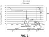
- FIG. 2compares a typical short-turnaround flight cycle with conventional single-idle to a multiple (e.g., asymmetric) idle.
- T3On the left side, during the cruise portion of first flight 50, T3 (also shown in FIG. 1 ) is elevated and substantially equal under both conventional and asymmetric (i.e., multiple idle) configurations. As cycle 50 comes to an end, T 3 drops significantly save for a short burst to operate the thrust reversers upon landing.
- Taxi in time rangeis represented by the time range 52. As the plane is being turned around for the next flight, the engines are off, shown by time range 54, then followed by taxi out range 56 and take off range 58 for second flight 60.
- the thermal cycle of engine 10(shown in FIG. 1 ) with an asymmetric idle is less than it would be (differential 64) without a second higher idle speed during taxi in.
- the enginewould be configured for a single idle, the same between taxi in and out.
- the asymmetric idle configurationallows for a higher compressor idle speed (and thus higher T 3 ) as the aircraft approaches the gate, hangar, or other deboarding area as compared to the taxi out speed or conventional single idle speed.
- a second optional type of ground idlecan be added for taxi in, different from the lower speed and same or lower power ground idle used to taxi out, while also substantially maintaining the same level of efficiency on other components.
- the higher taxi-in ratingmay be used in order to keep T 3 (compressor exit temperature) relatively high for as long as possible, higher than a comparable T 3 for the low-idle setting.
- the simplest way for this to be adapted to conventional engine designs such as in FIG. 1is to transfer the excess power from the low spool to a higher spool (the HP spool in a two-spool engine, as well as the HP and/or IP spool, not shown, in a three-spool engine).
- Thiscan be done in several ways, either through a geared or other mechanical connection, or more likely, through a combination of a generator connected to the low(er) spool and a motor powered (directly or indirectly) by the generator to assist with driving the high spool.
- Compressor efficiency spoilingcan also be implemented via vanes, as well as power addition/subtraction via motors/generators. This can be done directly or indirectly through use of a larger starter generator and/or a separate boost motor for the compressor so that less turbine power is needed to drive the compressor as compared to a conventional arrangement whereby the compressor is driven solely by the corresponding turbine side of each spool. These arrangements also allows for a quicker spool-up of the engine on takeoff, potentially shortening the takeoff run and adding flexibility to operate at more airfields.
- Compressioncan be augmented by a separate high spool motor as well (e.g., electrically operated) and may allow higher T 3 without the normally associated high T 4 (turbine inlet temperature).
- a separate high spool motore.g., electrically operated
- T 3turbine inlet temperature
- offtakessuch as bleed or transfer to higher pressure compressor or spool
- the offtakesinclude one or more components allowing the aircraft to be a hybrid aircraft such as an electric propulsion unit and means for storing energy to power same (e.g., batteries).
- the electric propulsion unitcan be operable, via the controller, in series or parallel with the combustion turbine engine.
- the electric propulsion unitprovides additional power input to at least one spool, allowing the turbine(s) to provide more exhaust and/or fan thrust without additional fuel burn during one or more parts of the flight cycle.
- Certain embodiments of the arrangement described hereinalso have particular synergy with more electric aircraft and hybrid aircraft. In most cases, the aircraft would land with relatively empty batteries, having been mostly depleted during flight.
- the batteries on the aircraftwould be mostly charged (e.g., 80% to 90% of usable capacity) with airside or gate power as the plane is being turned around for the next takeoff.
- the enginecould operate on low idle during taxi out to "top off the batteries and/or balance the individual cells using a relatively low rate of charge from the generator(s).
- power from the low spoolcould be transferred directly or indirectly (as described above) to the high spool to increase T 3 (without unduly increasing T 4 ) to minimize thermal cycling of the compressor during rapid turnarounds.
- FIG. 3shows an example decision tree, which can take the form of a manual or electronic checklist, depending on the parameters of a particular aircraft and expected flight cycle.
- Chart 100includes step 102, which corresponds to the end of thrust reverser operation as the aircraft begins to exit the runway.
- step 104it is determined whether or not a "rapid" turnaround is expected for the aircraft of less than or equal to 'x' minutes. If the expected turnaround time is less than or equal to 'x', then the answer is yes and the engine will be run at high, or reduced thermal cycle idle (106A) between the runway and the gate or other deboarding location. If the answer is no (expected turnaround time exceeds 'x'), the engine can default to conventional or low idle (106B) during at least part of the end of the flight cycle.
- 106Areduced thermal cycle idle
- 106Bconventional or low idle
- the value 'x'will vary according to several variables, but in the most general sense, it should not exceed the time necessary for the T 3 temperature to approach ambient. Because as seen in FIG. 2 , the goal is to reduce the magnitude of the thermal cycle between shutdown and the next start. Therefore, the value of 'x' can depend on airfield conditions, the cooldown rate of the particular materials, likelihood of delays at a particular airfield, among others.
- the high idleis operative on taxi in and the low idle is operative on taxi out.
- the controlleris operative to accept an input corresponding to expected turnaround time between a taxi in and a following taxi out. And in certain of these embodiments, from at least the input, the controller is configured to determine whether the taxi in operation should begin with the low idle or the high idle.
Landscapes
- Engineering & Computer Science (AREA)
- Chemical & Material Sciences (AREA)
- Combustion & Propulsion (AREA)
- Mechanical Engineering (AREA)
- General Engineering & Computer Science (AREA)
- Physics & Mathematics (AREA)
- Fluid Mechanics (AREA)
- Engine Equipment That Uses Special Cycles (AREA)
- Control Of Turbines (AREA)
Description
- The disclosure generally relates to combustion turbine engines and more specifically to reduce thermal cycling of such engines for aircraft.
- Idle of gas turbine engines generally requires low thrust and fuel flow, preferably as low as possible for both. Conventionally, this means that compressor exit temperature is fairly low, yet some parts of the engine, such as the rear compressor disks and/or hub can be disadvantaged by low idle temperatures, by causing broader thermal cycles and reduced durability.
US 7997085 A2 discloses a prior art engine assembly according to the preamble ofclaim 1.- A first aspect provides an engine assembly as set forth in
claim 1. - Another aspect provides a method of operating an aircraft as set forth in claim 6.
- Features of embodiments of the invention are set forth in the dependent claims.
FIG. 1 shows a quarter-section view of a turbofan engine and accompanying offtakes engine offtake options and configurations to take advantage of multiple idle configurations for advanced engine configurations.FIG. 2 shows a conventional thermal cycle with a single idle versus a revised thermal cycle with multiple idle options.FIG. 3 is a basic decision tree for determining a preferred operational idle mode based on expected turnaround time of an aircraft.FIG. 1 is a representative, yet non-limiting illustration ofgas turbine engine 10. The view inFIG. 1 is a longitudinal quarter-sectional view along engine center line CL.FIG. 1 showsgas turbine engine 10 includingfan 12,compressor 14,combustor 16,turbine 18, high-pressure rotor 20, low-pressure rotor 22, andengine casing 24.Turbine 18 includesrotor stages 26 andstator stages 28.Engine 10 includeslow spool 30 including low-pressure rotor 22 with a shaft connecting a low pressure portion ofcompressor 14 and a low pressure portion ofturbine 18, as well ashigh spool 32 which includeshigh pressure rotor 20 having a coaxial shaft connecting high pressure portion ofcompressor 14 to a high pressure portion ofturbine 18.FIG. 1 also showsoptional speed reducer 34, which can be an epicyclic gearbox or other device that connects and reduces the speed offan 12 relative to low-speed rotor 30. In embodiments omittingspeed reducer 34, it will be appreciated that inmost cases fan 12 will also be directly connected tolow spool 30 and driven by low-pressure rotor 22. The example shown is a two-spool design but it will be appreciated that the disclosure and claims can readily be adapted to, for example, a three-spool engine which would include an intermediate spool as well (not shown).- As illustrated in
FIG. 1 ,fan 12 is positioned along engine center line (CL) at one end ofgas turbine engine 10.Compressor 14 isadjacent fan 12 along engine center line CL, followed bycombustor 16. Turbine 18 is locatedadjacent combustor 16,opposite compressor 14. High-pressure rotor 20 and low-pressure rotor 22 are mounted for rotation about engine center line CL. High-pressure rotor 20 connects a high-pressure section ofturbine 18 tocompressor 14. Low-pressure rotor 22 connects a low-pressure section ofturbine 18 tofan 12.Rotor stages 26 andstator stages 28 are arranged throughoutturbine 18 in alternating rows.Rotor stages 26 connect to high-pressure rotor 20 and low-pressure rotor 22.Engine casing 24surrounds turbine engine 10 providing structural support forcompressor 14,combustor 16, andturbine 18, as well as containment for cooling air flows, as described below. - In operation, air flow F enters
compressor 14 throughfan 12 and is split into core flow Fp and bypass flow Fs. Air flow Fp is compressed by the rotation ofcompressor 14 driven by high-pressure rotor 20. The compressed air fromcompressor 14 is further divided, with a large portion going tocombustor 16, and a smaller portion employed for cooling components exposed to high-temperature combustion gases, such as stator vanes, as described below. Compressed air and fuel are mixed an ignited incombustor 16 to produce high-temperature, high-pressure combustion gases Fp. Combustion core gases Fpexit combustor section 16 intoturbine section 18.Stator stages 28 properly align the flow of combustion gases Fp for an efficient attack angle onsubsequent rotor stages 26. The flow of combustion gases Fppast rotor stages 26 drives rotation of both high-pressure rotor 20 and low-pressure rotor 22. High-pressure rotor 20 drives at least the high-pressure part ofcompressor section 14, as noted above, and low-pressure rotor 22 drives at least the low-pressure part ofcompressor 14, as well asfan 12, either directly or indirectly, to produce thrust fromgas turbine engine 10. In this example,engine 10 has two spools,low pressure spool 30 andhigh pressure spool 32.FIG. 1 also showsfan drive gearbox 34 being driven bylow pressure spool 30 to allow for lower and more efficient fan speeds as compared to speed of the low-pressure part ofcompressor 14. - Further,
engine 10 is connected to various accessories orofftakes 35, only a relevant few of which are shown here. Accessories orofftakes 35 are generally connected to the compressor side oflow spool 30 and/orhigh spool 32, most often via one ormore tower shafts 36, and "take off' energy generated byengine 10. In this case,tower shaft 36links engine 10 to starter generator (S/G) 38. As apparent from the name, starter/generator 38 provides power to rotate engine 10 (specificallylow spool 30,high spool 32, and/or the omitted intermediate spool) upon startup. It also generates electricity during operation of the engine for various uses, the excess of which can be stored in battery (+/-) 40. Accessories 35 also includeboost 42, regarded generally as a motive device, potentially operable via stored energy (such as via battery 40), to increase rotational speed of one or more rotors, such as during certain idle and taxi mode(s). Boost 42 can also be an electric propulsion unit, operable in series and/or parallel withengine 10, such as for a hybrid electric aircraft, and can draw stored power from enlarged battery unit(s) 40.Boost 42 is shown as a separate item, but in certain embodiments, it can take the form of a starter/generator 38 that is larger than would otherwise be called for in a conventional arrangement. It can also be a dedicated motor powered by electricity. There are other examples as well, which will be explained in the context of the disclosure.Controller 44 is programmed to operateengine 10 and one ormore offtakes 35 to facilitate the operations herein.- As is generally known in the art,
combustion turbine engines 10 conventionally operate in a range between a single ground idle setting and maximum takeoff/climb power setting. In some cases, even the ground idle setting, such as for engines with high thrust ratings, is high enough that the ground idle setting results in minimum thrust and speed that exceeds many airfield speed restrictions (on the order of 20 mph / 32 kph to 30 mph / 48 kph) during both taxi out (e.g., from the gate or boarding area to the runway) and taxi in (e.g., from runway exit to the gate or boarding area). This discrepancy between minimum idle thrust required to safely operate the engine, and resulting aircraft speed, can cause excess use of the aircraft brakes and more importantly, additional wear on hot section components. Further, even in cases where the single baseline ground idle setting is sufficient to maintain aircraft taxi speed within an acceptable range, the low baseline ground idle setting increases the range of thermal expansion and contraction of certain engine parts during ever faster aircraft / gate turnaround times. - In such cases, the quick turnaround results in more frequent and extreme thermal cycling of parts such as the rear / aft compressor components. As it is exposed to pressurized gas for the duration of a flight cycle, this area represented by T3 (compressor exit temperature) also cools relatively quickly, not having been in contact with combustion products such as in the turbine / hot section. Therefore, this area has been found to be rather prone to thermal cycle fatigue as compared to other sections as the number of flight cycles increase in each engine.
- Merely increasing the base ground idle speed would not be enough as the extra thrust generated thereby in a conventional engine configuration would need to be "burned" off such as by the aircraft brakes in order to maintain safe and compliant ground speed. The increased T4 (turbine inlet temperature) from a higher base idle setting would also cause unwanted wear and fatigue on the even more expensive turbine / hot section hardware.
FIG. 2 compares a typical short-turnaround flight cycle with conventional single-idle to a multiple (e.g., asymmetric) idle. On the left side, during the cruise portion offirst flight 50, T3 (also shown inFIG. 1 ) is elevated and substantially equal under both conventional and asymmetric (i.e., multiple idle) configurations. Ascycle 50 comes to an end, T3 drops significantly save for a short burst to operate the thrust reversers upon landing.- "Taxi in" time range is represented by the
time range 52. As the plane is being turned around for the next flight, the engines are off, shown bytime range 54, then followed by taxi outrange 56 and take offrange 58 forsecond flight 60. - As shown by the
differential 62, the thermal cycle of engine 10 (shown inFIG. 1 ) with an asymmetric idle is less than it would be (differential 64) without a second higher idle speed during taxi in. In a conventional operation, the engine would be configured for a single idle, the same between taxi in and out. Comparatively, the asymmetric idle configuration allows for a higher compressor idle speed (and thus higher T3) as the aircraft approaches the gate, hangar, or other deboarding area as compared to the taxi out speed or conventional single idle speed. - Of course, if the engine is expected to be off (time range 54) for a long period of time (e.g., overnight) and/or is otherwise subject to a deep cold soak in certain extreme climates, there may be minimal benefit to implementing the higher taxi in idle speed for a particular turnaround cycle.
- Therefore, as seen in
FIG. 2 , a second optional type of ground idle can be added for taxi in, different from the lower speed and same or lower power ground idle used to taxi out, while also substantially maintaining the same level of efficiency on other components. On taxi in, specifically when fast turnaround is expected, the higher taxi-in rating may be used in order to keep T3 (compressor exit temperature) relatively high for as long as possible, higher than a comparable T3 for the low-idle setting. Thus the thermal cycle when the engine is off for a short period of time is less extreme. Ordinarily this would represent a waste of power and fuel, but in some cases, the additional marginal fuel burn could be more than offset by the reduced costs and downtime associated with less thermal cycle fatigue. The simplest way for this to be adapted to conventional engine designs such as inFIG. 1 is to transfer the excess power from the low spool to a higher spool (the HP spool in a two-spool engine, as well as the HP and/or IP spool, not shown, in a three-spool engine). This can be done in several ways, either through a geared or other mechanical connection, or more likely, through a combination of a generator connected to the low(er) spool and a motor powered (directly or indirectly) by the generator to assist with driving the high spool. - Compressor efficiency spoiling can also be implemented via vanes, as well as power addition/subtraction via motors/generators. This can be done directly or indirectly through use of a larger starter generator and/or a separate boost motor for the compressor so that less turbine power is needed to drive the compressor as compared to a conventional arrangement whereby the compressor is driven solely by the corresponding turbine side of each spool. These arrangements also allows for a quicker spool-up of the engine on takeoff, potentially shortening the takeoff run and adding flexibility to operate at more airfields.
- Beyond this, additional power demands, accessories, and other advancements in modern aircraft design may also benefit from this higher taxi in idle speed without increasing net idle thrust in several non-limiting ways. As noted, without somewhere for the additional output power to go, this would increase wear on brakes and other components to maintain airfield speed restrictions and other limitations. Therefore, in some cases, more power can be extracted in the high(er) idle mode from the low or (optional) intermediate spool, versus the lower ground idle / taxi out mode while also using comparable amounts of fuel.
- Compression can be augmented by a separate high spool motor as well (e.g., electrically operated) and may allow higher T3 without the normally associated high T4 (turbine inlet temperature). In general, sub-idle fuel flow (or no fuel flow at all) where offtakes (such as bleed or transfer to higher pressure compressor or spool) are handled differently between taxi in and taxi out to achieve a higher T3 or an economic benefit respectively. This would be especially relevant for configurations that have more potential offtake sources available versus conventional aircraft, such as a hybrid or a more electric aircraft.
- In certain embodiments, the offtakes include one or more components allowing the aircraft to be a hybrid aircraft such as an electric propulsion unit and means for storing energy to power same (e.g., batteries). The electric propulsion unit can be operable, via the controller, in series or parallel with the combustion turbine engine. In one example, the electric propulsion unit provides additional power input to at least one spool, allowing the turbine(s) to provide more exhaust and/or fan thrust without additional fuel burn during one or more parts of the flight cycle. Certain embodiments of the arrangement described herein also have particular synergy with more electric aircraft and hybrid aircraft. In most cases, the aircraft would land with relatively empty batteries, having been mostly depleted during flight. It would be expected that the batteries on the aircraft would be mostly charged (e.g., 80% to 90% of usable capacity) with airside or gate power as the plane is being turned around for the next takeoff. Thus the engine could operate on low idle during taxi out to "top off the batteries and/or balance the individual cells using a relatively low rate of charge from the generator(s). And on taxi-in, power from the low spool could be transferred directly or indirectly (as described above) to the high spool to increase T3 (without unduly increasing T4) to minimize thermal cycling of the compressor during rapid turnarounds.
FIG. 3 shows an example decision tree, which can take the form of a manual or electronic checklist, depending on the parameters of a particular aircraft and expected flight cycle.Chart 100 includesstep 102, which corresponds to the end of thrust reverser operation as the aircraft begins to exit the runway. At step 104, it is determined whether or not a "rapid" turnaround is expected for the aircraft of less than or equal to 'x' minutes. If the expected turnaround time is less than or equal to 'x', then the answer is yes and the engine will be run at high, or reduced thermal cycle idle (106A) between the runway and the gate or other deboarding location. If the answer is no (expected turnaround time exceeds 'x'), the engine can default to conventional or low idle (106B) during at least part of the end of the flight cycle.- The value 'x' will vary according to several variables, but in the most general sense, it should not exceed the time necessary for the T3 temperature to approach ambient. Because as seen in
FIG. 2 , the goal is to reduce the magnitude of the thermal cycle between shutdown and the next start. Therefore, the value of 'x' can depend on airfield conditions, the cooldown rate of the particular materials, likelihood of delays at a particular airfield, among others. - Per
FIG. 3 , as noted, the high idle is operative on taxi in and the low idle is operative on taxi out. In certain embodiments, the controller is operative to accept an input corresponding to expected turnaround time between a taxi in and a following taxi out. And in certain of these embodiments, from at least the input, the controller is configured to determine whether the taxi in operation should begin with the low idle or the high idle. - The invention is defined by the scope of the appended claims.
Claims (13)
- An engine assembly comprising:a multi-spool combustion turbine engine (10) including a high pressure spool (32) which includes a high pressure portion of a compressor (14) and at least one lower pressure spool (30);a plurality of offtakes (35) powered by the combustion turbine engine (10), at least one of the plurality of offtakes (35) configured to selectively take power from the at least one lower pressure spool (30); anda controller (44) configured to operate the combustion turbine engine (10) through a range between a first low-idle mode, a second high-idle mode, and a maximum takeoff power rating mode;wherein the controller (44) is configured to operate the engine in the low-idle mode by directing at least a first portion of power from the at least one lower pressure spool (30) to the plurality of offtakes (35), and wherein the controller (44) is configured to operate the engine (10) in the high-idle mode by increasing a speed of the high pressure spool (32) relative to a speed of the high pressure spool (32) in the low-idle mode, thereby increasing a compressor outlet T3 temperature in the high-idle mode relative to a compressor outlet T3 temperature in the low-idle mode;characterised in that:the controller is configured to operate the engine in either the high-idle mode or the low idle mode on taxi-in and is configured to operate the engine in the low-idle mode on taxi-out; andin thata selection of the low-idle mode or high-idle mode on taxi-in depends at least in part on an expected turnaround time of the engine (10) between a taxi-in and a following taxi-out.
- The engine assembly of claim 1, wherein the controller (44) is operative to accept an input corresponding to the expected turnaround time of the engine (10).
- The engine assembly of any preceding claim, wherein the high-idle mode includes directing at least a second portion of power from the at least one lower pressure spool (30) to the high pressure spool (32).
- The engine assembly of any preceding claim, further comprising a generator connected to the lower pressure spool (30) and a corresponding motor connected to the high pressure spool (32), wherein the controller (44) is configured to operate the generator and the motor to selectively transfer a portion of power from the at least one lower pressure spool (30) to the high pressure spool (32).
- The engine assembly of any preceding claim, further comprising a geared interface between the at least one lower pressure spool (30) and the high pressure spool (32), wherein the controller (44) is configured to operate the geared interface to selectively transfer a portion of power from the at least one lower pressure spool (30) to the high pressure spool (32).
- A method of operating an aircraft, the method comprising:selectively operating an engine assembly including a multi-spool combustion turbine engine (10) and a plurality of offtakes (35), the engine assembly operable through a range between a first low-idle mode, a second high-idle mode, and a maximum takeoff power rating mode; andpowering the plurality of offtakes (35) by connection to at least one lower pressure spool (30) of the combustion turbine engine (10), at least one of the plurality of offtakes (35) configured to selectively take power from the at least one lower pressure spool (30);wherein the combustion turbine engine (10) operates in the low-idle mode by directing at least a first portion of power from the at least one lower pressure spool (30) to the plurality of offtakes (35), and wherein the combustion turbine engine (10) operates in the high-idle mode by increasing a speed of a high pressure spool (32) which includes a high pressure portion of a compressor (14) relative to a speed of the high pressure spool (32) in the low-idle mode, thereby increasing a compressor outlet T3 temperature in the high-idle mode relative to a compressor outlet T3 temperature in the low-idle mode;characterised in that:
the combustion turbine engine operates in either the high-idle mode or the low-idle mode on taxi-in based on an expected turnaround time of the engine between a taxi-in and a following taxi-out and the combustion turbine engine operates in the low-idle mode on taxi-out. - The method of claim 6, further comprising:accepting an input corresponding to the expected turnaround time between a taxi-in and a following taxi-out; andfrom at least the input, determining whether the taxi-in operation should begin with the low-idle mode or the high-idle mode.
- The method of claim 6 or 7, wherein at least a second portion of power is directed from the at least one lower pressure spool (30) to the high pressure spool (32) .
- The engine assembly or method of any preceding claim, wherein the plurality of offtakes (35) comprises one or more of a starter/generator (38), a boost motor (42), and an electric propulsion unit.
- The engine assembly or method of any preceding claim, wherein the engine assembly is a hybrid engine assembly further comprising an/the electric propulsion unit and a means for storing energy to power the electric propulsion unit.
- The engine assembly or method of claim 9 or 10, wherein the electric propulsion unit is operable in series or parallel with the combustion turbine engine (10).
- The engine assembly or method of any preceding claim, wherein the high-idle mode includes operating the plurality of offtakes (35) from the at least one lower pressure spool (30) to charge batteries (40) at a first charging rate to retain the increased idle speed and increased compressor outlet T3 temperature relative to the idle speed and the compressor outlet T3 temperature of the low-idle mode.
- The engine assembly or method of claim 12, wherein the low-idle mode includes operating the plurality of offtakes (35) from the lower pressure spool (30) to charge batteries (40) at a second charging rate lower than the first charging rate.
Applications Claiming Priority (1)
| Application Number | Priority Date | Filing Date | Title |
|---|---|---|---|
| US16/104,579US10995674B2 (en) | 2018-08-17 | 2018-08-17 | Modified aircraft idle for reduced thermal cycling |
Publications (2)
| Publication Number | Publication Date |
|---|---|
| EP3611360A1 EP3611360A1 (en) | 2020-02-19 |
| EP3611360B1true EP3611360B1 (en) | 2024-02-28 |
Family
ID=67658590
Family Applications (1)
| Application Number | Title | Priority Date | Filing Date |
|---|---|---|---|
| EP19190790.6AActiveEP3611360B1 (en) | 2018-08-17 | 2019-08-08 | Modified aircraft idle for reduced thermal cycling |
Country Status (2)
| Country | Link |
|---|---|
| US (1) | US10995674B2 (en) |
| EP (1) | EP3611360B1 (en) |
Families Citing this family (10)
| Publication number | Priority date | Publication date | Assignee | Title |
|---|---|---|---|---|
| US11214378B2 (en)* | 2018-08-21 | 2022-01-04 | Zunum Aero, Inc. | System controller for series hybrid powertrain |
| US11312503B1 (en) | 2018-12-17 | 2022-04-26 | Zunum Aero, Inc. | Systems and methods for implementing lightweight and reliable hybrid or electric powertrains for aircraft |
| US11199139B2 (en) | 2018-12-19 | 2021-12-14 | Raytheon Technologies Corporation | Gas turbine engine system bowed rotor start mitigation and wear reduction |
| US11306654B2 (en) | 2018-12-19 | 2022-04-19 | Raytheon Technologies Corporation | Gas turbine engine system wear reduction |
| US12060834B2 (en) | 2021-05-07 | 2024-08-13 | Rtx Corporation | Hybrid electric idle and braking for an aircraft |
| US20220397067A1 (en)* | 2021-06-09 | 2022-12-15 | Raytheon Technologies Corporation | Hybrid electric idle transition for aircraft |
| US12421902B2 (en) | 2021-07-29 | 2025-09-23 | Safran Helicopter Engines | Transfer of power between the high-pressure shaft and the low-pressure shaft of a turbomachine |
| FR3125848B1 (en)* | 2021-07-29 | 2023-07-21 | Safran Helicopter Engines | POWER TRANSFER BETWEEN THE HIGH PRESSURE SHAFT AND THE LOW PRESSURE SHAFT OF A TURBOMACHINE |
| FR3125847B1 (en)* | 2021-07-29 | 2023-07-14 | Safran Helicopter Engines | POWER TRANSFER BETWEEN THE HIGH PRESSURE SHAFT AND THE LOW PRESSURE SHAFT OF A TURBOMACHINE |
| US12434849B2 (en) | 2021-08-06 | 2025-10-07 | Rtx Corporation | Energy optimization for a hybrid electric engine |
Family Cites Families (18)
| Publication number | Priority date | Publication date | Assignee | Title |
|---|---|---|---|---|
| US7805947B2 (en)* | 2005-05-19 | 2010-10-05 | Djamal Moulebhar | Aircraft with disengageable engine and auxiliary power unit components |
| US7802757B2 (en)* | 2005-11-09 | 2010-09-28 | Pratt & Whitney Canada Corp. | Method and system for taxiing an aircraft |
| US7997085B2 (en)* | 2006-09-27 | 2011-08-16 | General Electric Company | Gas turbine engine assembly and method of assembling same |
| US7622817B2 (en)* | 2006-12-13 | 2009-11-24 | General Electric Company | High-speed high-pole count generators |
| FR2912782B1 (en)* | 2007-02-19 | 2009-05-22 | Snecma Sa | METHOD FOR COLLECTING AUXILIARY ENERGY ON AN AIRCRAFT TURBOJET AND TURBOJET ENGINE EQUIPPED TO IMPLEMENT SUCH A METHOD |
| US8015828B2 (en) | 2007-04-03 | 2011-09-13 | General Electric Company | Power take-off system and gas turbine engine assembly including same |
| US20100126178A1 (en)* | 2008-10-08 | 2010-05-27 | Searete Llc, A Limited Liability Corporation Of The State Of Delaware | Hybrid propulsive engine including at least one independently rotatable turbine stator |
| US8109073B2 (en)* | 2008-10-08 | 2012-02-07 | The Invention Science Fund I, Llc | Hybrid propulsive engine including at least one independently rotatable compressor stator |
| US8093747B2 (en)* | 2009-12-03 | 2012-01-10 | Honeywell International, Inc. | Aircraft electrical power system architecture using auxiliary power unit during approach and taxi |
| US8684304B2 (en)* | 2010-11-16 | 2014-04-01 | Rolls-Royce Corporation | Aircraft, propulsion system, and system for taxiing an aircraft |
| US20130327014A1 (en) | 2012-06-12 | 2013-12-12 | Djamal Moulebhar | Devices and Methods to Optimize Aircraft Power Plant and Aircraft Operations |
| GB201403178D0 (en)* | 2014-02-24 | 2014-04-09 | Rolls Royce Plc | Electrical power generator for a gas turbine engine |
| FR3024755B1 (en)* | 2014-08-08 | 2019-06-21 | Safran Aircraft Engines | HYBRIDIZING THE COMPRESSORS OF A TURBOJET ENGINE |
| CN115946858A (en)* | 2014-08-29 | 2023-04-11 | 峰鸟航空科技公司 | Systems and methods for implementing a regional air transportation network using hybrid electric aircraft |
| US10240521B2 (en)* | 2015-08-07 | 2019-03-26 | Pratt & Whitney Canada Corp. | Auxiliary power unit with variable speed ratio |
| US10180080B2 (en)* | 2016-03-09 | 2019-01-15 | Rolls-Royce North American Technologies, Inc. | Electromagnetic propeller brake |
| US20180002025A1 (en) | 2016-07-01 | 2018-01-04 | United Technologies Corporation | Aircraft including parallel hybrid gas turbine electric propulsion system |
| US10208675B2 (en)* | 2017-03-15 | 2019-02-19 | The Boeing Company | Hybrid drive system for transferring power from a gas turbine engine of an aircraft |
- 2018
- 2018-08-17USUS16/104,579patent/US10995674B2/enactiveActive
- 2019
- 2019-08-08EPEP19190790.6Apatent/EP3611360B1/enactiveActive
Also Published As
| Publication number | Publication date |
|---|---|
| US10995674B2 (en) | 2021-05-04 |
| US20200056549A1 (en) | 2020-02-20 |
| EP3611360A1 (en) | 2020-02-19 |
Similar Documents
| Publication | Publication Date | Title |
|---|---|---|
| EP3611360B1 (en) | Modified aircraft idle for reduced thermal cycling | |
| US11939925B2 (en) | Descent operation for an aircraft parallel hybrid gas turbine engine propulsion system | |
| CA3060753C (en) | Hybrid electric propulsion with superposition gearbox | |
| US11149649B2 (en) | Hybrid gas turbine engine system powered warm-up | |
| EP2617980B1 (en) | Gas turbine engines | |
| EP3751121B1 (en) | Improving deceleration of a gas turbine | |
| EP3751116B1 (en) | Generating electrical power at high thrust conditions | |
| US11371430B2 (en) | Power system for aircraft parallel hybrid gas turbine electric propulsion system | |
| US20180002025A1 (en) | Aircraft including parallel hybrid gas turbine electric propulsion system | |
| EP3613970B1 (en) | Aircaft engine idle suppressor and method | |
| EP3751115B1 (en) | Improving acceleration of a gas turbine | |
| GB2588073A (en) | Limiting spool speeds in a gas turbine engine | |
| GB2584697A (en) | Varying the bypass ratio of a turbofan engine | |
| GB2588074A (en) | Reducing idle thrust in a propulsive gas turbine | |
| EP3751117B1 (en) | Increasing compression efficiency via shaft power transfer | |
| GB2584694A (en) | Preventing surge | |
| US20230184130A1 (en) | Restarting a gas turbine engine | |
| EP3751114B1 (en) | Reducing low flight mach number fuel consumption in a gas turbine with electric machines | |
| US12244209B2 (en) | Aircraft powerplant with boosted gas turbine engine | |
| GB2584690A (en) | Increasing surge margin via shaft power transfer | |
| US12334859B2 (en) | Gas-turbine electrical start system | |
| US12234022B2 (en) | Electrical energy system for barring rotor | |
| EP4424979A1 (en) | Core compartment vent during engine shutdown to reduced bowed rotor start | |
| GB2584691A (en) | Increasing compression efficiency |
Legal Events
| Date | Code | Title | Description |
|---|---|---|---|
| PUAI | Public reference made under article 153(3) epc to a published international application that has entered the european phase | Free format text:ORIGINAL CODE: 0009012 | |
| STAA | Information on the status of an ep patent application or granted ep patent | Free format text:STATUS: THE APPLICATION HAS BEEN PUBLISHED | |
| AK | Designated contracting states | Kind code of ref document:A1 Designated state(s):AL AT BE BG CH CY CZ DE DK EE ES FI FR GB GR HR HU IE IS IT LI LT LU LV MC MK MT NL NO PL PT RO RS SE SI SK SM TR | |
| STAA | Information on the status of an ep patent application or granted ep patent | Free format text:STATUS: REQUEST FOR EXAMINATION WAS MADE | |
| 17P | Request for examination filed | Effective date:20200819 | |
| RBV | Designated contracting states (corrected) | Designated state(s):AL AT BE BG CH CY CZ DE DK EE ES FI FR GB GR HR HU IE IS IT LI LT LU LV MC MK MT NL NO PL PT RO RS SE SI SK SM TR | |
| RAP1 | Party data changed (applicant data changed or rights of an application transferred) | Owner name:RAYTHEON TECHNOLOGIES CORPORATION | |
| STAA | Information on the status of an ep patent application or granted ep patent | Free format text:STATUS: EXAMINATION IS IN PROGRESS | |
| 17Q | First examination report despatched | Effective date:20220201 | |
| GRAP | Despatch of communication of intention to grant a patent | Free format text:ORIGINAL CODE: EPIDOSNIGR1 | |
| STAA | Information on the status of an ep patent application or granted ep patent | Free format text:STATUS: GRANT OF PATENT IS INTENDED | |
| INTG | Intention to grant announced | Effective date:20230914 | |
| RIN1 | Information on inventor provided before grant (corrected) | Inventor name:VIRTUE, JOHN P. Inventor name:TERWILLIGER, NEIL | |
| RAP3 | Party data changed (applicant data changed or rights of an application transferred) | Owner name:RTX CORPORATION | |
| GRAS | Grant fee paid | Free format text:ORIGINAL CODE: EPIDOSNIGR3 | |
| GRAA | (expected) grant | Free format text:ORIGINAL CODE: 0009210 | |
| STAA | Information on the status of an ep patent application or granted ep patent | Free format text:STATUS: THE PATENT HAS BEEN GRANTED | |
| AK | Designated contracting states | Kind code of ref document:B1 Designated state(s):AL AT BE BG CH CY CZ DE DK EE ES FI FR GB GR HR HU IE IS IT LI LT LU LV MC MK MT NL NO PL PT RO RS SE SI SK SM TR | |
| REG | Reference to a national code | Ref country code:GB Ref legal event code:FG4D | |
| REG | Reference to a national code | Ref country code:CH Ref legal event code:EP | |
| REG | Reference to a national code | Ref country code:DE Ref legal event code:R096 Ref document number:602019047206 Country of ref document:DE | |
| REG | Reference to a national code | Ref country code:IE Ref legal event code:FG4D | |
| REG | Reference to a national code | Ref country code:LT Ref legal event code:MG9D | |
| PG25 | Lapsed in a contracting state [announced via postgrant information from national office to epo] | Ref country code:IS Free format text:LAPSE BECAUSE OF FAILURE TO SUBMIT A TRANSLATION OF THE DESCRIPTION OR TO PAY THE FEE WITHIN THE PRESCRIBED TIME-LIMIT Effective date:20240628 | |
| REG | Reference to a national code | Ref country code:NL Ref legal event code:MP Effective date:20240228 | |
| PG25 | Lapsed in a contracting state [announced via postgrant information from national office to epo] | Ref country code:LT Free format text:LAPSE BECAUSE OF FAILURE TO SUBMIT A TRANSLATION OF THE DESCRIPTION OR TO PAY THE FEE WITHIN THE PRESCRIBED TIME-LIMIT Effective date:20240228 | |
| PG25 | Lapsed in a contracting state [announced via postgrant information from national office to epo] | Ref country code:GR Free format text:LAPSE BECAUSE OF FAILURE TO SUBMIT A TRANSLATION OF THE DESCRIPTION OR TO PAY THE FEE WITHIN THE PRESCRIBED TIME-LIMIT Effective date:20240529 | |
| PG25 | Lapsed in a contracting state [announced via postgrant information from national office to epo] | Ref country code:NL Free format text:LAPSE BECAUSE OF FAILURE TO SUBMIT A TRANSLATION OF THE DESCRIPTION OR TO PAY THE FEE WITHIN THE PRESCRIBED TIME-LIMIT Effective date:20240228 Ref country code:RS Free format text:LAPSE BECAUSE OF FAILURE TO SUBMIT A TRANSLATION OF THE DESCRIPTION OR TO PAY THE FEE WITHIN THE PRESCRIBED TIME-LIMIT Effective date:20240528 Ref country code:HR Free format text:LAPSE BECAUSE OF FAILURE TO SUBMIT A TRANSLATION OF THE DESCRIPTION OR TO PAY THE FEE WITHIN THE PRESCRIBED TIME-LIMIT Effective date:20240228 | |
| PG25 | Lapsed in a contracting state [announced via postgrant information from national office to epo] | Ref country code:ES Free format text:LAPSE BECAUSE OF FAILURE TO SUBMIT A TRANSLATION OF THE DESCRIPTION OR TO PAY THE FEE WITHIN THE PRESCRIBED TIME-LIMIT Effective date:20240228 | |
| PG25 | Lapsed in a contracting state [announced via postgrant information from national office to epo] | Ref country code:RS Free format text:LAPSE BECAUSE OF FAILURE TO SUBMIT A TRANSLATION OF THE DESCRIPTION OR TO PAY THE FEE WITHIN THE PRESCRIBED TIME-LIMIT Effective date:20240528 Ref country code:NO Free format text:LAPSE BECAUSE OF FAILURE TO SUBMIT A TRANSLATION OF THE DESCRIPTION OR TO PAY THE FEE WITHIN THE PRESCRIBED TIME-LIMIT Effective date:20240528 Ref country code:NL Free format text:LAPSE BECAUSE OF FAILURE TO SUBMIT A TRANSLATION OF THE DESCRIPTION OR TO PAY THE FEE WITHIN THE PRESCRIBED TIME-LIMIT Effective date:20240228 Ref country code:LT Free format text:LAPSE BECAUSE OF FAILURE TO SUBMIT A TRANSLATION OF THE DESCRIPTION OR TO PAY THE FEE WITHIN THE PRESCRIBED TIME-LIMIT Effective date:20240228 Ref country code:IS Free format text:LAPSE BECAUSE OF FAILURE TO SUBMIT A TRANSLATION OF THE DESCRIPTION OR TO PAY THE FEE WITHIN THE PRESCRIBED TIME-LIMIT Effective date:20240628 Ref country code:HR Free format text:LAPSE BECAUSE OF FAILURE TO SUBMIT A TRANSLATION OF THE DESCRIPTION OR TO PAY THE FEE WITHIN THE PRESCRIBED TIME-LIMIT Effective date:20240228 Ref country code:GR Free format text:LAPSE BECAUSE OF FAILURE TO SUBMIT A TRANSLATION OF THE DESCRIPTION OR TO PAY THE FEE WITHIN THE PRESCRIBED TIME-LIMIT Effective date:20240529 Ref country code:FI Free format text:LAPSE BECAUSE OF FAILURE TO SUBMIT A TRANSLATION OF THE DESCRIPTION OR TO PAY THE FEE WITHIN THE PRESCRIBED TIME-LIMIT Effective date:20240228 Ref country code:ES Free format text:LAPSE BECAUSE OF FAILURE TO SUBMIT A TRANSLATION OF THE DESCRIPTION OR TO PAY THE FEE WITHIN THE PRESCRIBED TIME-LIMIT Effective date:20240228 Ref country code:BG Free format text:LAPSE BECAUSE OF FAILURE TO SUBMIT A TRANSLATION OF THE DESCRIPTION OR TO PAY THE FEE WITHIN THE PRESCRIBED TIME-LIMIT Effective date:20240228 | |
| PG25 | Lapsed in a contracting state [announced via postgrant information from national office to epo] | Ref country code:PL Free format text:LAPSE BECAUSE OF FAILURE TO SUBMIT A TRANSLATION OF THE DESCRIPTION OR TO PAY THE FEE WITHIN THE PRESCRIBED TIME-LIMIT Effective date:20240228 Ref country code:PT Free format text:LAPSE BECAUSE OF FAILURE TO SUBMIT A TRANSLATION OF THE DESCRIPTION OR TO PAY THE FEE WITHIN THE PRESCRIBED TIME-LIMIT Effective date:20240628 | |
| REG | Reference to a national code | Ref country code:AT Ref legal event code:MK05 Ref document number:1661451 Country of ref document:AT Kind code of ref document:T Effective date:20240228 | |
| PG25 | Lapsed in a contracting state [announced via postgrant information from national office to epo] | Ref country code:SE Free format text:LAPSE BECAUSE OF FAILURE TO SUBMIT A TRANSLATION OF THE DESCRIPTION OR TO PAY THE FEE WITHIN THE PRESCRIBED TIME-LIMIT Effective date:20240228 Ref country code:PT Free format text:LAPSE BECAUSE OF FAILURE TO SUBMIT A TRANSLATION OF THE DESCRIPTION OR TO PAY THE FEE WITHIN THE PRESCRIBED TIME-LIMIT Effective date:20240628 Ref country code:PL Free format text:LAPSE BECAUSE OF FAILURE TO SUBMIT A TRANSLATION OF THE DESCRIPTION OR TO PAY THE FEE WITHIN THE PRESCRIBED TIME-LIMIT Effective date:20240228 Ref country code:LV Free format text:LAPSE BECAUSE OF FAILURE TO SUBMIT A TRANSLATION OF THE DESCRIPTION OR TO PAY THE FEE WITHIN THE PRESCRIBED TIME-LIMIT Effective date:20240228 | |
| PGFP | Annual fee paid to national office [announced via postgrant information from national office to epo] | Ref country code:DE Payment date:20240723 Year of fee payment:6 | |
| PG25 | Lapsed in a contracting state [announced via postgrant information from national office to epo] | Ref country code:DK Free format text:LAPSE BECAUSE OF FAILURE TO SUBMIT A TRANSLATION OF THE DESCRIPTION OR TO PAY THE FEE WITHIN THE PRESCRIBED TIME-LIMIT Effective date:20240228 | |
| PG25 | Lapsed in a contracting state [announced via postgrant information from national office to epo] | Ref country code:SM Free format text:LAPSE BECAUSE OF FAILURE TO SUBMIT A TRANSLATION OF THE DESCRIPTION OR TO PAY THE FEE WITHIN THE PRESCRIBED TIME-LIMIT Effective date:20240228 | |
| PGFP | Annual fee paid to national office [announced via postgrant information from national office to epo] | Ref country code:GB Payment date:20240723 Year of fee payment:6 | |
| PGFP | Annual fee paid to national office [announced via postgrant information from national office to epo] | Ref country code:FR Payment date:20240723 Year of fee payment:6 | |
| PG25 | Lapsed in a contracting state [announced via postgrant information from national office to epo] | Ref country code:EE Free format text:LAPSE BECAUSE OF FAILURE TO SUBMIT A TRANSLATION OF THE DESCRIPTION OR TO PAY THE FEE WITHIN THE PRESCRIBED TIME-LIMIT Effective date:20240228 Ref country code:CZ Free format text:LAPSE BECAUSE OF FAILURE TO SUBMIT A TRANSLATION OF THE DESCRIPTION OR TO PAY THE FEE WITHIN THE PRESCRIBED TIME-LIMIT Effective date:20240228 | |
| PG25 | Lapsed in a contracting state [announced via postgrant information from national office to epo] | Ref country code:AT Free format text:LAPSE BECAUSE OF FAILURE TO SUBMIT A TRANSLATION OF THE DESCRIPTION OR TO PAY THE FEE WITHIN THE PRESCRIBED TIME-LIMIT Effective date:20240228 | |
| PG25 | Lapsed in a contracting state [announced via postgrant information from national office to epo] | Ref country code:SK Free format text:LAPSE BECAUSE OF FAILURE TO SUBMIT A TRANSLATION OF THE DESCRIPTION OR TO PAY THE FEE WITHIN THE PRESCRIBED TIME-LIMIT Effective date:20240228 | |
| PG25 | Lapsed in a contracting state [announced via postgrant information from national office to epo] | Ref country code:SM Free format text:LAPSE BECAUSE OF FAILURE TO SUBMIT A TRANSLATION OF THE DESCRIPTION OR TO PAY THE FEE WITHIN THE PRESCRIBED TIME-LIMIT Effective date:20240228 Ref country code:SK Free format text:LAPSE BECAUSE OF FAILURE TO SUBMIT A TRANSLATION OF THE DESCRIPTION OR TO PAY THE FEE WITHIN THE PRESCRIBED TIME-LIMIT Effective date:20240228 Ref country code:RO Free format text:LAPSE BECAUSE OF FAILURE TO SUBMIT A TRANSLATION OF THE DESCRIPTION OR TO PAY THE FEE WITHIN THE PRESCRIBED TIME-LIMIT Effective date:20240228 Ref country code:EE Free format text:LAPSE BECAUSE OF FAILURE TO SUBMIT A TRANSLATION OF THE DESCRIPTION OR TO PAY THE FEE WITHIN THE PRESCRIBED TIME-LIMIT Effective date:20240228 Ref country code:DK Free format text:LAPSE BECAUSE OF FAILURE TO SUBMIT A TRANSLATION OF THE DESCRIPTION OR TO PAY THE FEE WITHIN THE PRESCRIBED TIME-LIMIT Effective date:20240228 Ref country code:CZ Free format text:LAPSE BECAUSE OF FAILURE TO SUBMIT A TRANSLATION OF THE DESCRIPTION OR TO PAY THE FEE WITHIN THE PRESCRIBED TIME-LIMIT Effective date:20240228 Ref country code:AT Free format text:LAPSE BECAUSE OF FAILURE TO SUBMIT A TRANSLATION OF THE DESCRIPTION OR TO PAY THE FEE WITHIN THE PRESCRIBED TIME-LIMIT Effective date:20240228 | |
| REG | Reference to a national code | Ref country code:DE Ref legal event code:R097 Ref document number:602019047206 Country of ref document:DE | |
| PG25 | Lapsed in a contracting state [announced via postgrant information from national office to epo] | Ref country code:IT Free format text:LAPSE BECAUSE OF FAILURE TO SUBMIT A TRANSLATION OF THE DESCRIPTION OR TO PAY THE FEE WITHIN THE PRESCRIBED TIME-LIMIT Effective date:20240228 | |
| PG25 | Lapsed in a contracting state [announced via postgrant information from national office to epo] | Ref country code:IT Free format text:LAPSE BECAUSE OF FAILURE TO SUBMIT A TRANSLATION OF THE DESCRIPTION OR TO PAY THE FEE WITHIN THE PRESCRIBED TIME-LIMIT Effective date:20240228 | |
| PLBE | No opposition filed within time limit | Free format text:ORIGINAL CODE: 0009261 | |
| STAA | Information on the status of an ep patent application or granted ep patent | Free format text:STATUS: NO OPPOSITION FILED WITHIN TIME LIMIT | |
| 26N | No opposition filed | Effective date:20241129 | |
| REG | Reference to a national code | Ref country code:CH Ref legal event code:PL | |
| PG25 | Lapsed in a contracting state [announced via postgrant information from national office to epo] | Ref country code:LU Free format text:LAPSE BECAUSE OF NON-PAYMENT OF DUE FEES Effective date:20240808 | |
| PG25 | Lapsed in a contracting state [announced via postgrant information from national office to epo] | Ref country code:SI Free format text:LAPSE BECAUSE OF FAILURE TO SUBMIT A TRANSLATION OF THE DESCRIPTION OR TO PAY THE FEE WITHIN THE PRESCRIBED TIME-LIMIT Effective date:20240228 Ref country code:MC Free format text:LAPSE BECAUSE OF FAILURE TO SUBMIT A TRANSLATION OF THE DESCRIPTION OR TO PAY THE FEE WITHIN THE PRESCRIBED TIME-LIMIT Effective date:20240228 Ref country code:CH Free format text:LAPSE BECAUSE OF NON-PAYMENT OF DUE FEES Effective date:20240831 | |
| REG | Reference to a national code | Ref country code:BE Ref legal event code:MM Effective date:20240831 | |
| PG25 | Lapsed in a contracting state [announced via postgrant information from national office to epo] | Ref country code:BE Free format text:LAPSE BECAUSE OF NON-PAYMENT OF DUE FEES Effective date:20240831 | |
| PG25 | Lapsed in a contracting state [announced via postgrant information from national office to epo] | Ref country code:IE Free format text:LAPSE BECAUSE OF NON-PAYMENT OF DUE FEES Effective date:20240808 |