EP3609450B1 - Device configured to transport a human body - Google Patents
Device configured to transport a human bodyDownload PDFInfo
- Publication number
- EP3609450B1 EP3609450B1EP18725314.1AEP18725314AEP3609450B1EP 3609450 B1EP3609450 B1EP 3609450B1EP 18725314 AEP18725314 AEP 18725314AEP 3609450 B1EP3609450 B1EP 3609450B1
- Authority
- EP
- European Patent Office
- Prior art keywords
- frame
- main frame
- support state
- supports
- support
- Prior art date
- Legal status (The legal status is an assumption and is not a legal conclusion. Google has not performed a legal analysis and makes no representation as to the accuracy of the status listed.)
- Active
Links
- 230000009466transformationEffects0.000claimsdescription19
- 230000000295complement effectEffects0.000claimsdescription2
- 230000002787reinforcementEffects0.000description3
- 235000004443Ricinus communisNutrition0.000description2
- QVGXLLKOCUKJST-UHFFFAOYSA-Natomic oxygenChemical compound[O]QVGXLLKOCUKJST-UHFFFAOYSA-N0.000description2
- 238000006243chemical reactionMethods0.000description2
- 208000014674injuryDiseases0.000description2
- 229910052760oxygenInorganic materials0.000description2
- 239000001301oxygenSubstances0.000description2
- 230000008733traumaEffects0.000description2
- 208000003443UnconsciousnessDiseases0.000description1
- 230000001419dependent effectEffects0.000description1
- 239000003814drugSubstances0.000description1
- 230000002708enhancing effectEffects0.000description1
- 230000001605fetal effectEffects0.000description1
- 230000005484gravityEffects0.000description1
- 238000007665saggingMethods0.000description1
- 208000020431spinal cord injuryDiseases0.000description1
Images


Classifications
- A—HUMAN NECESSITIES
- A61—MEDICAL OR VETERINARY SCIENCE; HYGIENE
- A61G—TRANSPORT, PERSONAL CONVEYANCES, OR ACCOMMODATION SPECIALLY ADAPTED FOR PATIENTS OR DISABLED PERSONS; OPERATING TABLES OR CHAIRS; CHAIRS FOR DENTISTRY; FUNERAL DEVICES
- A61G1/00—Stretchers
- A61G1/017—Stretchers convertible into chairs
- A—HUMAN NECESSITIES
- A61—MEDICAL OR VETERINARY SCIENCE; HYGIENE
- A61G—TRANSPORT, PERSONAL CONVEYANCES, OR ACCOMMODATION SPECIALLY ADAPTED FOR PATIENTS OR DISABLED PERSONS; OPERATING TABLES OR CHAIRS; CHAIRS FOR DENTISTRY; FUNERAL DEVICES
- A61G5/00—Chairs or personal conveyances specially adapted for patients or disabled persons, e.g. wheelchairs
- A61G5/006—Chairs or personal conveyances specially adapted for patients or disabled persons, e.g. wheelchairs convertible to stretchers or beds
- A—HUMAN NECESSITIES
- A61—MEDICAL OR VETERINARY SCIENCE; HYGIENE
- A61G—TRANSPORT, PERSONAL CONVEYANCES, OR ACCOMMODATION SPECIALLY ADAPTED FOR PATIENTS OR DISABLED PERSONS; OPERATING TABLES OR CHAIRS; CHAIRS FOR DENTISTRY; FUNERAL DEVICES
- A61G5/00—Chairs or personal conveyances specially adapted for patients or disabled persons, e.g. wheelchairs
- A61G5/10—Parts, details or accessories
- A61G5/12—Rests specially adapted therefor, e.g. for the head or the feet
- A61G5/128—Rests specially adapted therefor, e.g. for the head or the feet for feet
- A—HUMAN NECESSITIES
- A61—MEDICAL OR VETERINARY SCIENCE; HYGIENE
- A61G—TRANSPORT, PERSONAL CONVEYANCES, OR ACCOMMODATION SPECIALLY ADAPTED FOR PATIENTS OR DISABLED PERSONS; OPERATING TABLES OR CHAIRS; CHAIRS FOR DENTISTRY; FUNERAL DEVICES
- A61G1/00—Stretchers
- A61G1/02—Stretchers with wheels
- A—HUMAN NECESSITIES
- A61—MEDICAL OR VETERINARY SCIENCE; HYGIENE
- A61G—TRANSPORT, PERSONAL CONVEYANCES, OR ACCOMMODATION SPECIALLY ADAPTED FOR PATIENTS OR DISABLED PERSONS; OPERATING TABLES OR CHAIRS; CHAIRS FOR DENTISTRY; FUNERAL DEVICES
- A61G2200/00—Information related to the kind of patient or his position
- A61G2200/30—Specific positions of the patient
- A61G2200/32—Specific positions of the patient lying
Definitions
- the present inventionrelates to a device, in particular to a transport device that is configured to transport a human body, such as a patient.
- Transport devicesthat are configured to transport a human body exist in various embodiments, including stretchers in various forms, wheel chairs, etc.
- Ambulance personnelare exposed to various physically demanding situations during work. For example, raising a stretcher, carrying heavy equipment, riding with (heavy) patients on slopes and curbs, and evacuating patients on stairs impose a physical load for the personnel.
- DE 33 20 866is considered the closest prior art, relative to which at least the characterizing features of claim 1 are novel. It discloses a device configured to transport a patient, wherein a lying patient may be brought into a somewhat seated posture. However, in order to transport the patient, the main frame has to be tilted backward until the wheel, that is arranged about midway the length of the main frame, contacts the ground. The patient is thus merely in a lying position during transport. Moreover, conversion takes effort and time, also requiring storing away of handle bars.
- US 3 921 231discloses a break-away scoop stretcher composed of three detachable frame sections adapted to be selectively interengaged to extricate and transport a critically injured person in various positions, including prone, seated and fetal, depending upon the position in which the injured person is found.
- the conversion of the transport device of US 3 921 231takes considerable effort and time, wherein the three frame sections may have to be detached and combined again in another configuration. For example, from scoop to seat, the parts have to be taken apart, and a middle section has to be removed, before a backing section and a seating section are combined again. In an emergency situation, the time required to adapt this prior art device may make the difference between life and death of an injured person.
- An object of the present inventionis to provide a device, that is improved relative to the prior art and wherein at least one of the above stated problems is obviated.
- the planar support stateis configured to support a human body in a lying state or in a seating state, wherein the back is not supported.
- the angled support statewherein supports enclose an angle to define a seat and backing support, is configured to support a human body in a seating state, offering back support.
- the device according to the inventioncan be adapted to a specific situation.
- the angled support statecan be used, offering improved maneuverability relative to a stretcher-like planar support state. Research has shown that many patients could be transported while sitting upright or under a slight back angle.
- the devicein the angled support state, may also be used as an equipment trolley, allowing ambulance personnel to comfortably and securely transport their heavy medical equipment towards an emergency.
- the deviceOn the way back to the ambulance, the device may be used in its angled support state as either an equipment trolley or as a wheel chair for transporting a patient.
- a stable wheelchair or equipment trolleyis obtained by the leg sub frame that is extended to beyond its hinge relative to the main frame and that comprises a set of wheels at the free end of the extended leg sub frame.
- the extended leg sub frameis configured to provide a sturdy wheel base in the angled support state to define a wheel chair mode.
- the extended leg sub framepositions the wheels at a mutual distance that is sufficient to provide a sturdy wheel base. In this way, a human body or equipment may be easily and safely transported in the wheelchair mode of the transport device. In wheelchair mode, the center of gravity of the transport device and human body is substantially centered between the wheels.
- the support framefurther comprises a backing sub frame that is displaceably hinged relative to the main frame.
- the devicethus comprises the support frame that comprises the seat sub frame, the leg sub frame, and the backing sub frame.
- the seat sub frameis hingedly connected to the leg sub frame at a first side thereof, and hingedly connected to the backing sub frame at a second side thereof, wherein the first side and second side are opposite sideds of the seat sub frame. If both the backing sub frame and the seat sub frame are displaceably hinged relative to the main frame, and the leg sub frame is fixedly hinged relative to the main frame, the transport device may be converted between the planar support state and the angled support state, and vice versa, at a great ease of handling, providing improved operability.
- the device 1is a transport device that is configured to transport a human body 2, such as a patient.
- Device 1comprises a main frame 3 and supports 4.
- a transformation mechanism 5 that is associated with the main frame 3is configured to convert the device 1 between a planar support state ( Figure 1 ) and an angled support state ( Figure 2 ), wherein supports 4 enclose an angle ⁇ to define a seat 6 and backing support 7, and vice versa.
- the supportsare arranged in a support frame that is movably connected to the main frame 3, wherein the support frame 12 comprises a seat sub frame 12-2 and a leg sub frame 12-1, and preferably a backing sub frame 12-3.
- leg sub frame 12-1is fixedly hinged relative to the main frame 3, and the seat sub frame 12-2 is displaceably hinged relative to the main frame 3.
- the leg sub frame 12-1pivots around a pivot axis 17' ( Figures 3 and 4 ).
- the leg sub frame 12-1is extended to beyond its hinge 17", i.e. pivot axis 17', relative to the main frame 3 and comprises a set of wheels 14 at the free end of the extended leg sub frame 12-1, wherein the extended leg sub frame 12-1 is configured to provide a sturdy wheel base in the angled support state to define a wheel chair mode.
- the pivot axis 17'is arranged along a longitudinal direction of the main frame 3, at a distance from the one or more than one wheel 15 that is associated with the main frame 3. and that is arranged at an end of said main frame 3.
- two wheels 15 in the form of castor wheelsare applied.
- the distance d between the wheels 15 associated with the main frame 3 and the hinge 17" of the leg sub frame 12-1, i.e. pivot axis 17',allows the wheels 14 that are arranged at the free end of the extended leg sub frame 12-1 to be arranged at a distance from the one or more than one wheel 15 that is associated with the main frame 3. In this way, a sturdy wheel base is guaranteed.
- the shown device 1comprises four supports 4, allowing the human body 2 to be supported over substantially most of its surface ( Figure 8C ) in an essentially lying position of said body 2. At least two supports 4 are required to provide a seat 6 and backing support 7 in the angled support state.
- the main frame 3comprises two sub main frames 8a, 8b that divide the main frame 3 in two complementary halves. This can be best seen in Figure 8A .
- the sub main frames 8a, 8bare pivotably ( Figure 8B ) and/or releasably ( Figure 8A ) connected, allowing the device 1 to be used as a scoop stretcher.
- Scoop stretchersare most frequently used to lift injured people from the ground, either because of unconsciousness or in order to maintain stability in the case of trauma with suspected spinal cord injury. Scoop stretchers reduce the chance of undesirable movement of injured areas during transfer of a trauma patient, as they maintain the patient in a supine alignment during transfer.
- the connection between the sub main frames 8a, 8bpreferably comprises a safety hinge 10.
- One or more than one of the supports 4comprises two support parts 9a, 9b, wherein the support parts 9a, 9b are each connected to one of the sub main frames 8a, 8b of the main frame 3.
- all supports 4comprise two support parts 9a, 9b, as shown in the figures.
- the supportsare preferably reinforced.
- the device 1preferably comprises a connection 11 configured to connect two support parts 9a, 9b of a support 4 in at least the angled support state.
- the connection 11( Figure 9D ) may comprise a flexible (Velcro®) band or a rigid link.
- a further reinforcementmay be formed by a supporting bracket 22, that extends from the main frame 3 inward, and is configured to support the supports that provide the seat support 6 in the angled support state.
- the supporting bracket 2thus prevents sagging of the seat support 6 due to the weight of a human body sitting thereon.
- supports 4may also rest on the supporting bracket 22 in the planar support state.
- the supporting bracket 22thus also reinforces the planar support state.
- supporting bracket 22may support equipment. For example, it may function as an attachment for an oxygen bottle holder.
- a further reinforcementmay be formed by one or more than one additional supporting bracket 24 that is configured to support the supports 4 that are designed to receive a head and shoulder area of a human body 2.
- the additional supporting brackets 24may also be used as a handle for pushing the device 1 as a wheelchair.
- the supports 4are pivotable relative to each other, allowing the device 1 to be converted between the planar support state and the angled support state, wherein the supports 4 enclose an angle ⁇ to define a seat 6 and backing support 7, and vice versa.
- the supports 4are also moveable relative to the main frame 3, allowing the supports 4 to move towards each other when the device 1 is converted from the planar support state towards the angled support state.
- the supports 4are arranged in a support frame 12 that is movably connected to the main frame 3. More in particular, the support frame 12 is slideable relative to the main frame 3, e.g. using sliders 13 of the transformation mechanism 5.
- the transformation mechanism 5thus preferably comprises one or more than one slider 13 that slidingly and pivotably connects the support frame 12 to the main frame 3.
- the supports 4are pivotable relative to each other around pivot axes 16, using support frame 12 ( Figures 3 and 4 ).
- the support frame 12 and the supports 4are pivotable relative to the main frame 12 around pivot axes 17 ( Figures 3 and 4 ).
- slots 21that are configured for guiding a belt therethrough, are provided.
- the supports 4 that are configured to function as a footrest in the angled support statealso support feet of a human body in the planar support state shown in Figures 3 and 4 .
- These supportsare provided with slots 21 in the support 4 itself.
- the other slotsare formed between the supports 4 and the main frame 3.
- the sliders 13 and associated axes 17may form boundaries of said slots 21.
- the optional support frame 12is also considered part of the transformation mechanism 5.
- the supports 4may be directly linked to each other and sliders 13 without a support frame 12.
- the device 1comprises wheels 14 that are associated with the transformation mechanism 5 to be exposed and operational in at least one of the planar support state and the angled support state.
- the wheels 14are inoperative and in a storing position in the other of the planar support state and the angled support state.
- the wheels 14 that are associated with the transformation mechanism 5are exposed in the angled support state.
- the wheels 14 that are associated with the transformation mechanism 5are arranged on the support frame 12.
- the transformation mechanism 5comprises a cam 19 that is arranged on the main frame 3. This cam 19 engages a cam follower 20, and forces the wheels 14 against a spring force of a (not shown) spring into the exposed and operational state (indicated with arrow R in Figure 10 ) when the device 1 is converted from the planar support state to the angled support state.
- the wheels 14rotate relative to a rotation axis 18 ( Figures 4 and 10 ).
- the device 1further comprises one or more than one wheel 15 that is associated with the main frame 3.
- two wheels 15are shown, which allow the device 1 to be pulled away in the planar support state ( Figures 1 , 6 and 7 ) by a single paramedic.
- the wheels 15are preferably castor wheels, providing additional maneuverability to the device 1 when the device 1 functions as a wheel chair or equipment trolley in the angled support state thereof ( Figures 2 and 9D ).
- the transformation mechanism 5preferably further comprises a (not shown) lock that is configured to lock the supports 4 relative to the main frame 3 in at least one of the planar support state and the angled support state.
- a lockmay be arranged in a slider 13, locking the slider 13 relative to the main frame 3, and thus locking the support frame 12 and supports 4 relative to the main frame 3.
- the weight of the human bodymay push the sliders 13 against an end stop 23 ( Figure 9D ), which may comprise the lock of the transformation mechanism 5.
- An alternative lockmay lock the angle between adjacent supports 4.
- FIGS 5-7Successive states of extending the device 1 from a collapsed storing state ( Figure 5 ) to operational planar support states are shown in Figures 5-7 .
- the main frame 3is extendable and is extended in correspondence to the length of a patient 2.
- the main frame 3is lockable in a plurality of extended positions.
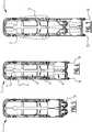
- Figure 6shows an intermediate extension for a small patient 2 and Figure 7 a full extension of the main frame 3 for supporting a large patient 2.
- the device 1may be converted from the planar support state of Figure 9A towards the angled support state of Figure 9D .
- Figures 9B and 9Cshow intermediate positions, wherein the sliders 13 of the transformation mechanism 5 slide along the main frame 3 and the support frame 12 gradually pivots the supports 4 relative towards each other until they end in the angled support state of Figure 9D , wherein two supports 4 enclose an angle ⁇ to define a seat 6 and backing support 7.
Landscapes
- Health & Medical Sciences (AREA)
- Life Sciences & Earth Sciences (AREA)
- Animal Behavior & Ethology (AREA)
- General Health & Medical Sciences (AREA)
- Public Health (AREA)
- Veterinary Medicine (AREA)
- Handcart (AREA)
Description
- The present invention relates to a device, in particular to a transport device that is configured to transport a human body, such as a patient.
- Transport devices that are configured to transport a human body exist in various embodiments, including stretchers in various forms, wheel chairs, etc.
- Ambulance personnel are exposed to various physically demanding situations during work. For example, raising a stretcher, carrying heavy equipment, riding with (heavy) patients on slopes and curbs, and evacuating patients on stairs impose a physical load for the personnel.
- Whereas prior art electric stretchers reduce the load of raising a stretcher with a human body on it, the heavy weight of around 70 kg and handling of the electric stretcher itself often results in paramedics leaving the electric stretcher in the ambulance and only carrying the items that they really need. The equipment, e.g. comprising a medicine bag, monitor, and oxygen bottle, may however weigh more than 30 kg. Insufficient room for manoeuvring an (electric) stretcher due to tight turns, limited width of doors, and small elevators, is another reason why such stretchers are often left in the ambulance.
DE 33 20 866 is considered the closest prior art, relative to which at least the characterizing features ofclaim 1 are novel. It discloses a device configured to transport a patient, wherein a lying patient may be brought into a somewhat seated posture. However, in order to transport the patient, the main frame has to be tilted backward until the wheel, that is arranged about midway the length of the main frame, contacts the ground. The patient is thus merely in a lying position during transport. Moreover, conversion takes effort and time, also requiring storing away of handle bars.US 3 921 231 discloses a break-away scoop stretcher composed of three detachable frame sections adapted to be selectively interengaged to extricate and transport a critically injured person in various positions, including prone, seated and fetal, depending upon the position in which the injured person is found. The conversion of the transport device ofUS 3 921 231 takes considerable effort and time, wherein the three frame sections may have to be detached and combined again in another configuration. For example, from scoop to seat, the parts have to be taken apart, and a middle section has to be removed, before a backing section and a seating section are combined again. In an emergency situation, the time required to adapt this prior art device may make the difference between life and death of an injured person.- The international patent application
WO 2915/149767 , theUnited States publications US 3 116 492 ,US 2015/320627 ,US 2007/182220 andUS 8 104 121 , as well as theUnited Kingdom patent application GB 2 360 255 - An object of the present invention is to provide a device, that is improved relative to the prior art and wherein at least one of the above stated problems is obviated.
- Said object is achieved with the device according to the present invention. comprising:
- a main frame;
- one or more than one wheel that is associated with the main frame;
- supports;
- wherein the supports are arranged in a support frame that is movably connected to the main frame;
- wherein the support frame comprises a seat sub frame and a leg sub frame;
- wherein one of the seat sub frame and the leg sub frame is fixedly hinged relative to the main frame, and wherein the other of the seat sub frame and the leg sub frame is displaceably hinged relative to the main frame; and
- a transformation mechanism associated with the main frame and configured to convert the device between a planar support state and an angled support state, wherein supports enclose an angle to define a seat and backing support, and vice versa;
- wherein the leg sub frame is extended to beyond its hinge relative to the main frame and comprises a set of wheels at the free end of the extended leg sub frame, wherein the extended leg sub frame is configured to provide a sturdy wheel base in the angled support state to define a wheel chair mode.
- The planar support state is configured to support a human body in a lying state or in a seating state, wherein the back is not supported. The angled support state, wherein supports enclose an angle to define a seat and backing support, is configured to support a human body in a seating state, offering back support.
- Consequently, the device according to the invention can be adapted to a specific situation. For people or patients that could be transported in a seating position, the angled support state can be used, offering improved maneuverability relative to a stretcher-like planar support state. Research has shown that many patients could be transported while sitting upright or under a slight back angle.
- Moreover, in the angled support state, the device may also be used as an equipment trolley, allowing ambulance personnel to comfortably and securely transport their heavy medical equipment towards an emergency. On the way back to the ambulance, the device may be used in its angled support state as either an equipment trolley or as a wheel chair for transporting a patient.
- A stable wheelchair or equipment trolley is obtained by the leg sub frame that is extended to beyond its hinge relative to the main frame and that comprises a set of wheels at the free end of the extended leg sub frame. The extended leg sub frame is configured to provide a sturdy wheel base in the angled support state to define a wheel chair mode. The extended leg sub frame positions the wheels at a mutual distance that is sufficient to provide a sturdy wheel base. In this way, a human body or equipment may be easily and safely transported in the wheelchair mode of the transport device. In wheelchair mode, the center of gravity of the transport device and human body is substantially centered between the wheels.
- In a preferred embodiment, the support frame further comprises a backing sub frame that is displaceably hinged relative to the main frame. The device thus comprises the support frame that comprises the seat sub frame, the leg sub frame, and the backing sub frame. The seat sub frame is hingedly connected to the leg sub frame at a first side thereof, and hingedly connected to the backing sub frame at a second side thereof, wherein the first side and second side are opposite sideds of the seat sub frame. If both the backing sub frame and the seat sub frame are displaceably hinged relative to the main frame, and the leg sub frame is fixedly hinged relative to the main frame, the transport device may be converted between the planar support state and the angled support state, and vice versa, at a great ease of handling, providing improved operability.
- Preferred embodiments are the subject of the dependent claims.
- In the following description preferred embodiments of the present invention are further elucidated with reference to the drawing, in which:
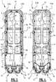
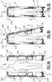
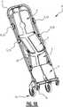
Figure 1 is a perspective view of a device according to the invention in a planar support state;Figure 2 is a perspective view of the device ofFigure 1 in an angled support state;Figure 3 shows a top view of the device in a collapsed storing state;Figure 4 shows a bottom plan view of the device in the collapsed storing state;Figures 5-7 show successive states of extending the device from the collapsed storing state to operational planar support states;Figures 8A - 8C show the device functioning as a scoop stretcher;Figures 9A - 9D show successive states of converting the device from a planar support state to an angled support state; andFigure 10 is a perspective detail view of the wheels of the device.- The
device 1 is a transport device that is configured to transport ahuman body 2, such as a patient.Device 1 comprises amain frame 3 and supports 4. Atransformation mechanism 5 that is associated with themain frame 3 is configured to convert thedevice 1 between a planar support state (Figure 1 ) and an angled support state (Figure 2 ), wherein supports 4 enclose an angle α to define aseat 6 andbacking support 7, and vice versa. - The supports are arranged in a support frame that is movably connected to the
main frame 3, wherein thesupport frame 12 comprises a seat sub frame 12-2 and a leg sub frame 12-1, and preferably a backing sub frame 12-3. - In the shown embodiment, the leg sub frame 12-1 is fixedly hinged relative to the
main frame 3, and the seat sub frame 12-2 is displaceably hinged relative to themain frame 3. The leg sub frame 12-1 pivots around a pivot axis 17' (Figures 3 and 4 ). - In the angled support state of
Figure 2 , the leg sub frame 12-1 is extended to beyond itshinge 17", i.e. pivot axis 17', relative to themain frame 3 and comprises a set ofwheels 14 at the free end of the extended leg sub frame 12-1, wherein the extended leg sub frame 12-1 is configured to provide a sturdy wheel base in the angled support state to define a wheel chair mode. - The pivot axis 17' is arranged along a longitudinal direction of the
main frame 3, at a distance from the one or more than onewheel 15 that is associated with themain frame 3. and that is arranged at an end of saidmain frame 3. In the shown embodiment, twowheels 15 in the form of castor wheels are applied. The distance d between thewheels 15 associated with themain frame 3 and thehinge 17" of the leg sub frame 12-1, i.e. pivot axis 17', allows thewheels 14 that are arranged at the free end of the extended leg sub frame 12-1 to be arranged at a distance from the one or more than onewheel 15 that is associated with themain frame 3. In this way, a sturdy wheel base is guaranteed. - The shown
device 1 comprises foursupports 4, allowing thehuman body 2 to be supported over substantially most of its surface (Figure 8C ) in an essentially lying position of saidbody 2. At least twosupports 4 are required to provide aseat 6 andbacking support 7 in the angled support state. - The
main frame 3 comprises two sub main frames 8a, 8b that divide themain frame 3 in two complementary halves. This can be best seen inFigure 8A . The sub main frames 8a, 8b are pivotably (Figure 8B ) and/or releasably (Figure 8A ) connected, allowing thedevice 1 to be used as a scoop stretcher. Scoop stretchers are most frequently used to lift injured people from the ground, either because of unconsciousness or in order to maintain stability in the case of trauma with suspected spinal cord injury. Scoop stretchers reduce the chance of undesirable movement of injured areas during transfer of a trauma patient, as they maintain the patient in a supine alignment during transfer. The connection between the sub main frames 8a, 8b preferably comprises asafety hinge 10. - One or more than one of the
supports 4 comprises twosupport parts support parts main frame 3. In order to allow thedevice 1 being used as a scoop stretcher, preferably all supports 4 comprise twosupport parts - In order to provide a stable support for the
human body 2 in the angled support state, the supports are preferably reinforced. As a reinforcement, thedevice 1 preferably comprises aconnection 11 configured to connect twosupport parts support 4 in at least the angled support state. The connection 11 (Figure 9D ) may comprise a flexible (Velcro®) band or a rigid link. - A further reinforcement may be formed by a supporting
bracket 22, that extends from themain frame 3 inward, and is configured to support the supports that provide theseat support 6 in the angled support state. The supportingbracket 2 thus prevents sagging of theseat support 6 due to the weight of a human body sitting thereon. - As shown in
Figures 3 and 4 , supports 4 may also rest on the supportingbracket 22 in the planar support state. The supportingbracket 22 thus also reinforces the planar support state. - Finally, supporting
bracket 22 may support equipment. For example, it may function as an attachment for an oxygen bottle holder. - A further reinforcement may be formed by one or more than one additional supporting
bracket 24 that is configured to support thesupports 4 that are designed to receive a head and shoulder area of ahuman body 2. In the angled support state, the additional supportingbrackets 24 may also be used as a handle for pushing thedevice 1 as a wheelchair. - The
supports 4 are pivotable relative to each other, allowing thedevice 1 to be converted between the planar support state and the angled support state, wherein thesupports 4 enclose an angle α to define aseat 6 andbacking support 7, and vice versa. - The
supports 4 are also moveable relative to themain frame 3, allowing thesupports 4 to move towards each other when thedevice 1 is converted from the planar support state towards the angled support state. - In the shown embodiment, especially in
Figures 2 and9B-9D , thesupports 4 are arranged in asupport frame 12 that is movably connected to themain frame 3. More in particular, thesupport frame 12 is slideable relative to themain frame 3,e.g. using sliders 13 of thetransformation mechanism 5. Thetransformation mechanism 5 thus preferably comprises one or more than oneslider 13 that slidingly and pivotably connects thesupport frame 12 to themain frame 3. - The
supports 4 are pivotable relative to each other around pivot axes 16, using support frame 12 (Figures 3 and 4 ). Thesupport frame 12 and thesupports 4 are pivotable relative to themain frame 12 around pivot axes 17 (Figures 3 and 4 ). - In order to allow paramedics to secure a human body to the
device 1 in the planar support state,slots 21 that are configured for guiding a belt therethrough, are provided. Thesupports 4 that are configured to function as a footrest in the angled support state also support feet of a human body in the planar support state shown inFigures 3 and 4 . These supports are provided withslots 21 in thesupport 4 itself. The other slots are formed between thesupports 4 and themain frame 3. Thesliders 13 and associatedaxes 17 may form boundaries of saidslots 21. - In the shown embodiment, the
optional support frame 12 is also considered part of thetransformation mechanism 5. The skilled person will however understand that it is conceivable that thesupports 4 may be directly linked to each other andsliders 13 without asupport frame 12. - In order to allow the
device 1 to be used as a wheel chair in the angled support state (Figure 2 ), thedevice 1 compriseswheels 14 that are associated with thetransformation mechanism 5 to be exposed and operational in at least one of the planar support state and the angled support state. Thewheels 14 are inoperative and in a storing position in the other of the planar support state and the angled support state. In the shown embodiment, thewheels 14 that are associated with thetransformation mechanism 5 are exposed in the angled support state. - The
wheels 14 that are associated with thetransformation mechanism 5 are arranged on thesupport frame 12. Thetransformation mechanism 5 comprises acam 19 that is arranged on themain frame 3. Thiscam 19 engages acam follower 20, and forces thewheels 14 against a spring force of a (not shown) spring into the exposed and operational state (indicated with arrow R inFigure 10 ) when thedevice 1 is converted from the planar support state to the angled support state. Thewheels 14 rotate relative to a rotation axis 18 (Figures 4 and10 ). - The
device 1 further comprises one or more than onewheel 15 that is associated with themain frame 3. InFigure 1 , twowheels 15 are shown, which allow thedevice 1 to be pulled away in the planar support state (Figures 1 ,6 and 7 ) by a single paramedic. Thewheels 15 are preferably castor wheels, providing additional maneuverability to thedevice 1 when thedevice 1 functions as a wheel chair or equipment trolley in the angled support state thereof (Figures 2 and9D ). - The
transformation mechanism 5 preferably further comprises a (not shown) lock that is configured to lock thesupports 4 relative to themain frame 3 in at least one of the planar support state and the angled support state. Such a lock may be arranged in aslider 13, locking theslider 13 relative to themain frame 3, and thus locking thesupport frame 12 and supports 4 relative to themain frame 3. The weight of the human body may push thesliders 13 against an end stop 23 (Figure 9D ), which may comprise the lock of thetransformation mechanism 5. An alternative lock may lock the angle betweenadjacent supports 4. - Successive states of extending the
device 1 from a collapsed storing state (Figure 5 ) to operational planar support states are shown inFigures 5-7 . Themain frame 3 is extendable and is extended in correspondence to the length of apatient 2. Themain frame 3 is lockable in a plurality of extended positions.Figure 6 shows an intermediate extension for asmall patient 2 andFigure 7 a full extension of themain frame 3 for supporting alarge patient 2. - After adjusting the length of the
device 1, it may be used as a scoop stretcher, shown inFigures 8A - 8C . - Alternatively, the
device 1 may be converted from the planar support state ofFigure 9A towards the angled support state ofFigure 9D .Figures 9B and9C show intermediate positions, wherein thesliders 13 of thetransformation mechanism 5 slide along themain frame 3 and thesupport frame 12 gradually pivots thesupports 4 relative towards each other until they end in the angled support state ofFigure 9D , wherein twosupports 4 enclose an angle α to define aseat 6 andbacking support 7. - The above described embodiment is intended only to illustrate the invention and not to limit in any way the scope of the invention. Accordingly, it should be understood that where features mentioned in the appended claims are followed by reference signs, such signs are included solely for the purpose of enhancing the intelligibility of the claims and are in no way limiting on the scope of the claims. The scope of the invention is defined solely by the following claims.
Claims (15)
- Device (1), comprising:- a main frame (3);- one or more than one wheel that is associated with the main frame (3);- supports (4);- wherein the supports (4) are arranged in a support frame (12) that is movably connected to the main frame (3);- wherein the support frame (12) comprises a seat sub frame (12-2) and a leg sub frame (12-1);- wherein one of the seat sub frame (12-2) and the leg sub frame (12-1) is fixedly hinged relative to the main frame (3), and wherein the other of the seat sub frame (12-2) and the leg sub frame (12-1) is displaceably hinged relative to the main frame (3); and- a transformation mechanism (5) associated with the main frame (3) and configured to convert the device between a planar support state and an angled support state, wherein supports (4) enclose an angle (α) to define a seat (6) and backing support (7), and vice versa;characterized in that, in the angled support state, the leg sub frame (12-1) is extended to beyond its hinge (17") relative to the main frame (3) and comprises a set of wheels (14) at the free end of the extended leg sub frame (12-1), wherein the extended leg sub frame (12-1) is configured to provide a sturdy wheel base in the angled support state to define a wheel chair mode.
- Device according to claim 1, wherein the support frame (12) further comprises a backing sub frame (12-3) that is displaceably hinged relative to the main frame (3).
- Device according to claim 1 or 2, wherein the main frame (3) comprises two sub main frames (8a, 8b) that divide the main frame (3) in two complementary halves.
- Device according to claim 3, wherein the sub main frames (8a, 8b) are pivotably and/or releasably connected.
- Device according to any of the foregoing claims, wherein the supports (4) are pivotable relative to each other.
- Device according to any of the foregoing claims, wherein the supports (4) are moveable relative to the main frame (3).
- Device according to any of claims 3-6, in dependency of at least claim 3 or 4, wherein one or more than one of the supports (4) comprises two support parts (9a, 9b), wherein the support parts (9a, 9b) are each connected to one of the sub main frames (8a, 8b) of the main frame (3).
- Device according to claim 7, comprising a connection (11) configured to connect said two support parts (9a, 9b) of one or more than one of said supports (4) in at least the angled support state.
- Device according to any of the foregoing claims, wherein the support frame (12) is slideable along the main frame (3).
- Device according to any of the foregoing claims, further comprising wheels (14) that are associated with the transformation mechanism (5) to be exposed and operational in at least one of the planar support state and the angled support state, and to be inoperative and in a storing position in the other of the planar support state and the angled support state.
- Device according to claim 10, wherein the wheels (14) that are associated with the transformation mechanism (5) are exposed in the angled support state.
- Device according to claim 10 or 11, wherein the wheels (14) that are associated with the transformation mechanism (5) are arranged on the support frame (12).
- Device according to any of the foregoing claims, wherein the transformation mechanism (5) comprises one or more than one slider (13) that slidingly connects the support frame (12) to the main frame (3).
- Device according to any of the foregoing claims, wherein the transformation mechanism (5) comprises a lock configured to lock the supports (4) relative to the main frame (3) in at least one of the planar support state and the angled support state.
- Device according to any of claims 10-14, in dependency of at least one of claims 10-12, wherein the transformation mechanism (5) comprises a cam (19) that forces the wheels (14) into the exposed and operational state when the device is converted from the planar support state to the angled support state.
Applications Claiming Priority (2)
| Application Number | Priority Date | Filing Date | Title |
|---|---|---|---|
| NL2018713ANL2018713B1 (en) | 2017-04-13 | 2017-04-13 | Device configured to transport a human body |
| PCT/NL2018/050222WO2018190709A1 (en) | 2017-04-13 | 2018-04-11 | Device configured to transport a human body |
Publications (2)
| Publication Number | Publication Date |
|---|---|
| EP3609450A1 EP3609450A1 (en) | 2020-02-19 |
| EP3609450B1true EP3609450B1 (en) | 2021-07-21 |
Family
ID=59351017
Family Applications (1)
| Application Number | Title | Priority Date | Filing Date |
|---|---|---|---|
| EP18725314.1AActiveEP3609450B1 (en) | 2017-04-13 | 2018-04-11 | Device configured to transport a human body |
Country Status (6)
| Country | Link |
|---|---|
| US (1) | US11399994B2 (en) |
| EP (1) | EP3609450B1 (en) |
| DK (1) | DK3609450T3 (en) |
| ES (1) | ES2886170T3 (en) |
| NL (1) | NL2018713B1 (en) |
| WO (1) | WO2018190709A1 (en) |
Families Citing this family (5)
| Publication number | Priority date | Publication date | Assignee | Title |
|---|---|---|---|---|
| US11304865B2 (en)* | 2017-06-27 | 2022-04-19 | Stryker Corporation | Patient support apparatus with adaptive user interface |
| US11535291B2 (en)* | 2019-03-13 | 2022-12-27 | Catherine A Hill | System and method for electrically assisting in removal of deceased humans up and down stairs and into a vehicle |
| US10967763B2 (en)* | 2019-03-21 | 2021-04-06 | Pratt & Miller Engineering and Fabrication, Inc. | Removable and convertible seat assembly |
| NL2025443B1 (en) | 2020-04-28 | 2021-11-09 | Retter Medical Holding B V | Transporter configured to transport a human body, and connector therefor |
| CN115737291A (en)* | 2022-12-26 | 2023-03-07 | 西安理工大学 | Stretcher for pre-hospital first aid |
Family Cites Families (13)
| Publication number | Priority date | Publication date | Assignee | Title |
|---|---|---|---|---|
| US3116492A (en)* | 1961-11-08 | 1964-01-07 | Ole B Christensen | Invalid lift |
| US3921231A (en)* | 1974-05-02 | 1975-11-25 | Ferno Washington | Combination adjustable break-away scoop stretcher and extrication device |
| DE3320866A1 (en)* | 1983-06-09 | 1984-12-13 | Utila Gerätebau GmbH & Co KG, 5000 Köln | Stretcher |
| DE3329866A1 (en) | 1983-08-18 | 1985-03-07 | Reuschenbach KG, 5461 Breitscheid | Roof structure |
| GB2360255A (en)* | 2000-03-16 | 2001-09-19 | David Healey | A foldable wheelchair |
| US20070182220A1 (en)* | 2005-02-22 | 2007-08-09 | Walkinshaw Nathan R | Folding Chair Cot For Use With Emergency Vehicles |
| US8104121B2 (en)* | 2006-02-01 | 2012-01-31 | Ferno-Washington, Inc. | Combination ambulance cot and chair |
| CN104736119B (en)* | 2013-09-17 | 2016-08-17 | 松下知识产权经营株式会社 | Wheelchair and combination cot |
| US20180168896A1 (en)* | 2014-03-20 | 2018-06-21 | ResQdevices Pty Ltd. | A transport and components therefor |
| WO2015149767A1 (en) | 2014-04-01 | 2015-10-08 | Schaeffler Technologies AG & Co. KG | Operation actuator |
| US11147726B2 (en)* | 2016-08-01 | 2021-10-19 | Stryker Corporation | Person support apparatus system |
| US11020293B2 (en)* | 2016-08-01 | 2021-06-01 | Stryker Corporation | Multi-function person handling equipment |
| US10744049B2 (en)* | 2016-12-30 | 2020-08-18 | Stryker Corporation | Patient transfer apparatus |
- 2017
- 2017-04-13NLNL2018713Apatent/NL2018713B1/ennot_activeIP Right Cessation
- 2018
- 2018-04-11WOPCT/NL2018/050222patent/WO2018190709A1/ennot_activeCeased
- 2018-04-11ESES18725314Tpatent/ES2886170T3/enactiveActive
- 2018-04-11USUS16/500,443patent/US11399994B2/enactiveActive
- 2018-04-11DKDK18725314.1Tpatent/DK3609450T3/enactive
- 2018-04-11EPEP18725314.1Apatent/EP3609450B1/enactiveActive
Non-Patent Citations (1)
| Title |
|---|
| None* |
Also Published As
| Publication number | Publication date |
|---|---|
| NL2018713B1 (en) | 2018-10-24 |
| WO2018190709A1 (en) | 2018-10-18 |
| WO2018190709A8 (en) | 2020-01-09 |
| US11399994B2 (en) | 2022-08-02 |
| DK3609450T3 (en) | 2021-08-30 |
| ES2886170T3 (en) | 2021-12-16 |
| US20200188199A1 (en) | 2020-06-18 |
| EP3609450A1 (en) | 2020-02-19 |
Similar Documents
| Publication | Publication Date | Title |
|---|---|---|
| EP3609450B1 (en) | Device configured to transport a human body | |
| US7578012B2 (en) | Patient transfer system with associated frames and lift carts | |
| US7950673B2 (en) | Stair chair | |
| US5502851A (en) | Assisted lifting, stand and walking device | |
| US7568240B2 (en) | Patient transfer system | |
| US7364184B2 (en) | Mobility assist devices | |
| US7140055B2 (en) | Lightweight mobile lift-assisted patient transport device | |
| US20190008710A1 (en) | Wheelchair Lift-Transfer Device | |
| US20130117929A1 (en) | Multi-functional patient transfer device | |
| US11213442B2 (en) | Mobility apparatus | |
| US20150342805A1 (en) | Mobile transportation device convertible to a trendelenburg table and for use in a motor vehicle and method thereof | |
| CA2954158C (en) | Assistive device, and method of use | |
| US11633322B1 (en) | Convertible wheelchair | |
| US11963921B2 (en) | Convertible walker | |
| KR20190080079A (en) | Assistive device for the elderly and people with disabilities transportation | |
| WO2011028761A2 (en) | Patient lifting and support device | |
| AU2012201566A1 (en) | Patient transfer system with associated frames and lift carts | |
| US11793694B2 (en) | Removably attached seat for a mobility apparatus | |
| GB2296901A (en) | Patient handling hoist and chair comprising a parallelogram linkage on a wheeled frame. | |
| EP2603187B1 (en) | Trolley for transporting individuals of limited capacity in sedentary position on chair | |
| US20020020987A1 (en) | Wheelchair |
Legal Events
| Date | Code | Title | Description |
|---|---|---|---|
| STAA | Information on the status of an ep patent application or granted ep patent | Free format text:STATUS: UNKNOWN | |
| STAA | Information on the status of an ep patent application or granted ep patent | Free format text:STATUS: THE INTERNATIONAL PUBLICATION HAS BEEN MADE | |
| PUAI | Public reference made under article 153(3) epc to a published international application that has entered the european phase | Free format text:ORIGINAL CODE: 0009012 | |
| STAA | Information on the status of an ep patent application or granted ep patent | Free format text:STATUS: REQUEST FOR EXAMINATION WAS MADE | |
| 17P | Request for examination filed | Effective date:20190905 | |
| AK | Designated contracting states | Kind code of ref document:A1 Designated state(s):AL AT BE BG CH CY CZ DE DK EE ES FI FR GB GR HR HU IE IS IT LI LT LU LV MC MK MT NL NO PL PT RO RS SE SI SK SM TR | |
| AX | Request for extension of the european patent | Extension state:BA ME | |
| DAV | Request for validation of the european patent (deleted) | ||
| DAX | Request for extension of the european patent (deleted) | ||
| RAP1 | Party data changed (applicant data changed or rights of an application transferred) | Owner name:RETTER MEDICAL HOLDING B.V. | |
| GRAP | Despatch of communication of intention to grant a patent | Free format text:ORIGINAL CODE: EPIDOSNIGR1 | |
| STAA | Information on the status of an ep patent application or granted ep patent | Free format text:STATUS: GRANT OF PATENT IS INTENDED | |
| INTG | Intention to grant announced | Effective date:20201120 | |
| GRAJ | Information related to disapproval of communication of intention to grant by the applicant or resumption of examination proceedings by the epo deleted | Free format text:ORIGINAL CODE: EPIDOSDIGR1 | |
| STAA | Information on the status of an ep patent application or granted ep patent | Free format text:STATUS: REQUEST FOR EXAMINATION WAS MADE | |
| GRAP | Despatch of communication of intention to grant a patent | Free format text:ORIGINAL CODE: EPIDOSNIGR1 | |
| STAA | Information on the status of an ep patent application or granted ep patent | Free format text:STATUS: GRANT OF PATENT IS INTENDED | |
| INTC | Intention to grant announced (deleted) | ||
| INTG | Intention to grant announced | Effective date:20210329 | |
| GRAS | Grant fee paid | Free format text:ORIGINAL CODE: EPIDOSNIGR3 | |
| GRAA | (expected) grant | Free format text:ORIGINAL CODE: 0009210 | |
| STAA | Information on the status of an ep patent application or granted ep patent | Free format text:STATUS: THE PATENT HAS BEEN GRANTED | |
| AK | Designated contracting states | Kind code of ref document:B1 Designated state(s):AL AT BE BG CH CY CZ DE DK EE ES FI FR GB GR HR HU IE IS IT LI LT LU LV MC MK MT NL NO PL PT RO RS SE SI SK SM TR | |
| REG | Reference to a national code | Ref country code:GB Ref legal event code:FG4D | |
| REG | Reference to a national code | Ref country code:CH Ref legal event code:EP | |
| REG | Reference to a national code | Ref country code:DE Ref legal event code:R096 Ref document number:602018020439 Country of ref document:DE | |
| REG | Reference to a national code | Ref country code:AT Ref legal event code:REF Ref document number:1411914 Country of ref document:AT Kind code of ref document:T Effective date:20210815 | |
| REG | Reference to a national code | Ref country code:IE Ref legal event code:FG4D | |
| REG | Reference to a national code | Ref country code:DK Ref legal event code:T3 Effective date:20210826 | |
| REG | Reference to a national code | Ref country code:FI Ref legal event code:FGE | |
| REG | Reference to a national code | Ref country code:SE Ref legal event code:TRGR | |
| REG | Reference to a national code | Ref country code:NL Ref legal event code:FP | |
| REG | Reference to a national code | Ref country code:NO Ref legal event code:T2 Effective date:20210721 | |
| REG | Reference to a national code | Ref country code:LT Ref legal event code:MG9D | |
| REG | Reference to a national code | Ref country code:ES Ref legal event code:FG2A Ref document number:2886170 Country of ref document:ES Kind code of ref document:T3 Effective date:20211216 | |
| PG25 | Lapsed in a contracting state [announced via postgrant information from national office to epo] | Ref country code:BG Free format text:LAPSE BECAUSE OF FAILURE TO SUBMIT A TRANSLATION OF THE DESCRIPTION OR TO PAY THE FEE WITHIN THE PRESCRIBED TIME-LIMIT Effective date:20211021 Ref country code:LT Free format text:LAPSE BECAUSE OF FAILURE TO SUBMIT A TRANSLATION OF THE DESCRIPTION OR TO PAY THE FEE WITHIN THE PRESCRIBED TIME-LIMIT Effective date:20210721 Ref country code:PT Free format text:LAPSE BECAUSE OF FAILURE TO SUBMIT A TRANSLATION OF THE DESCRIPTION OR TO PAY THE FEE WITHIN THE PRESCRIBED TIME-LIMIT Effective date:20211122 Ref country code:HR Free format text:LAPSE BECAUSE OF FAILURE TO SUBMIT A TRANSLATION OF THE DESCRIPTION OR TO PAY THE FEE WITHIN THE PRESCRIBED TIME-LIMIT Effective date:20210721 Ref country code:RS Free format text:LAPSE BECAUSE OF FAILURE TO SUBMIT A TRANSLATION OF THE DESCRIPTION OR TO PAY THE FEE WITHIN THE PRESCRIBED TIME-LIMIT Effective date:20210721 | |
| PG25 | Lapsed in a contracting state [announced via postgrant information from national office to epo] | Ref country code:PL Free format text:LAPSE BECAUSE OF FAILURE TO SUBMIT A TRANSLATION OF THE DESCRIPTION OR TO PAY THE FEE WITHIN THE PRESCRIBED TIME-LIMIT Effective date:20210721 Ref country code:LV Free format text:LAPSE BECAUSE OF FAILURE TO SUBMIT A TRANSLATION OF THE DESCRIPTION OR TO PAY THE FEE WITHIN THE PRESCRIBED TIME-LIMIT Effective date:20210721 Ref country code:GR Free format text:LAPSE BECAUSE OF FAILURE TO SUBMIT A TRANSLATION OF THE DESCRIPTION OR TO PAY THE FEE WITHIN THE PRESCRIBED TIME-LIMIT Effective date:20211022 | |
| REG | Reference to a national code | Ref country code:DE Ref legal event code:R097 Ref document number:602018020439 Country of ref document:DE | |
| PLBE | No opposition filed within time limit | Free format text:ORIGINAL CODE: 0009261 | |
| STAA | Information on the status of an ep patent application or granted ep patent | Free format text:STATUS: NO OPPOSITION FILED WITHIN TIME LIMIT | |
| PG25 | Lapsed in a contracting state [announced via postgrant information from national office to epo] | Ref country code:SM Free format text:LAPSE BECAUSE OF FAILURE TO SUBMIT A TRANSLATION OF THE DESCRIPTION OR TO PAY THE FEE WITHIN THE PRESCRIBED TIME-LIMIT Effective date:20210721 Ref country code:SK Free format text:LAPSE BECAUSE OF FAILURE TO SUBMIT A TRANSLATION OF THE DESCRIPTION OR TO PAY THE FEE WITHIN THE PRESCRIBED TIME-LIMIT Effective date:20210721 Ref country code:RO Free format text:LAPSE BECAUSE OF FAILURE TO SUBMIT A TRANSLATION OF THE DESCRIPTION OR TO PAY THE FEE WITHIN THE PRESCRIBED TIME-LIMIT Effective date:20210721 Ref country code:EE Free format text:LAPSE BECAUSE OF FAILURE TO SUBMIT A TRANSLATION OF THE DESCRIPTION OR TO PAY THE FEE WITHIN THE PRESCRIBED TIME-LIMIT Effective date:20210721 Ref country code:CZ Free format text:LAPSE BECAUSE OF FAILURE TO SUBMIT A TRANSLATION OF THE DESCRIPTION OR TO PAY THE FEE WITHIN THE PRESCRIBED TIME-LIMIT Effective date:20210721 Ref country code:AL Free format text:LAPSE BECAUSE OF FAILURE TO SUBMIT A TRANSLATION OF THE DESCRIPTION OR TO PAY THE FEE WITHIN THE PRESCRIBED TIME-LIMIT Effective date:20210721 | |
| 26N | No opposition filed | Effective date:20220422 | |
| PGFP | Annual fee paid to national office [announced via postgrant information from national office to epo] | Ref country code:NL Payment date:20220426 Year of fee payment:5 | |
| PGFP | Annual fee paid to national office [announced via postgrant information from national office to epo] | Ref country code:SE Payment date:20220427 Year of fee payment:5 Ref country code:NO Payment date:20220427 Year of fee payment:5 Ref country code:IT Payment date:20220421 Year of fee payment:5 Ref country code:IE Payment date:20220427 Year of fee payment:5 Ref country code:GB Payment date:20220427 Year of fee payment:5 Ref country code:FR Payment date:20220425 Year of fee payment:5 Ref country code:ES Payment date:20220503 Year of fee payment:5 Ref country code:DK Payment date:20220427 Year of fee payment:5 Ref country code:DE Payment date:20220427 Year of fee payment:5 | |
| PGFP | Annual fee paid to national office [announced via postgrant information from national office to epo] | Ref country code:FI Payment date:20220427 Year of fee payment:5 Ref country code:CH Payment date:20220503 Year of fee payment:5 Ref country code:BE Payment date:20220427 Year of fee payment:5 | |
| PG25 | Lapsed in a contracting state [announced via postgrant information from national office to epo] | Ref country code:MC Free format text:LAPSE BECAUSE OF FAILURE TO SUBMIT A TRANSLATION OF THE DESCRIPTION OR TO PAY THE FEE WITHIN THE PRESCRIBED TIME-LIMIT Effective date:20210721 Ref country code:LU Free format text:LAPSE BECAUSE OF NON-PAYMENT OF DUE FEES Effective date:20220411 | |
| REG | Reference to a national code | Ref country code:AT Ref legal event code:UEP Ref document number:1411914 Country of ref document:AT Kind code of ref document:T Effective date:20210721 | |
| REG | Reference to a national code | Ref country code:DE Ref legal event code:R119 Ref document number:602018020439 Country of ref document:DE | |
| REG | Reference to a national code | Ref country code:NO Ref legal event code:MMEP | |
| REG | Reference to a national code | Ref country code:DK Ref legal event code:EBP Effective date:20230430 | |
| REG | Reference to a national code | Ref country code:SE Ref legal event code:EUG | |
| REG | Reference to a national code | Ref country code:CH Ref legal event code:PL | |
| REG | Reference to a national code | Ref country code:NL Ref legal event code:MM Effective date:20230501 | |
| GBPC | Gb: european patent ceased through non-payment of renewal fee | Effective date:20230411 | |
| REG | Reference to a national code | Ref country code:BE Ref legal event code:MM Effective date:20230430 | |
| PG25 | Lapsed in a contracting state [announced via postgrant information from national office to epo] | Ref country code:GB Free format text:LAPSE BECAUSE OF NON-PAYMENT OF DUE FEES Effective date:20230411 | |
| PG25 | Lapsed in a contracting state [announced via postgrant information from national office to epo] | Ref country code:SE Free format text:LAPSE BECAUSE OF NON-PAYMENT OF DUE FEES Effective date:20230412 Ref country code:NO Free format text:LAPSE BECAUSE OF NON-PAYMENT OF DUE FEES Effective date:20230430 Ref country code:NL Free format text:LAPSE BECAUSE OF NON-PAYMENT OF DUE FEES Effective date:20230501 Ref country code:LI Free format text:LAPSE BECAUSE OF NON-PAYMENT OF DUE FEES Effective date:20230430 Ref country code:GB Free format text:LAPSE BECAUSE OF NON-PAYMENT OF DUE FEES Effective date:20230411 Ref country code:FR Free format text:LAPSE BECAUSE OF NON-PAYMENT OF DUE FEES Effective date:20230430 Ref country code:FI Free format text:LAPSE BECAUSE OF NON-PAYMENT OF DUE FEES Effective date:20230411 Ref country code:DE Free format text:LAPSE BECAUSE OF NON-PAYMENT OF DUE FEES Effective date:20231103 Ref country code:CH Free format text:LAPSE BECAUSE OF NON-PAYMENT OF DUE FEES Effective date:20230430 | |
| REG | Reference to a national code | Ref country code:IE Ref legal event code:MM4A | |
| PG25 | Lapsed in a contracting state [announced via postgrant information from national office to epo] | Ref country code:BE Free format text:LAPSE BECAUSE OF NON-PAYMENT OF DUE FEES Effective date:20230430 | |
| PG25 | Lapsed in a contracting state [announced via postgrant information from national office to epo] | Ref country code:IE Free format text:LAPSE BECAUSE OF NON-PAYMENT OF DUE FEES Effective date:20230411 | |
| PG25 | Lapsed in a contracting state [announced via postgrant information from national office to epo] | Ref country code:MK Free format text:LAPSE BECAUSE OF FAILURE TO SUBMIT A TRANSLATION OF THE DESCRIPTION OR TO PAY THE FEE WITHIN THE PRESCRIBED TIME-LIMIT Effective date:20210721 Ref country code:IT Free format text:LAPSE BECAUSE OF NON-PAYMENT OF DUE FEES Effective date:20230411 Ref country code:IE Free format text:LAPSE BECAUSE OF NON-PAYMENT OF DUE FEES Effective date:20230411 Ref country code:DK Free format text:LAPSE BECAUSE OF NON-PAYMENT OF DUE FEES Effective date:20230430 Ref country code:CY Free format text:LAPSE BECAUSE OF FAILURE TO SUBMIT A TRANSLATION OF THE DESCRIPTION OR TO PAY THE FEE WITHIN THE PRESCRIBED TIME-LIMIT Effective date:20210721 | |
| REG | Reference to a national code | Ref country code:ES Ref legal event code:FD2A Effective date:20240528 | |
| PG25 | Lapsed in a contracting state [announced via postgrant information from national office to epo] | Ref country code:HU Free format text:LAPSE BECAUSE OF FAILURE TO SUBMIT A TRANSLATION OF THE DESCRIPTION OR TO PAY THE FEE WITHIN THE PRESCRIBED TIME-LIMIT; INVALID AB INITIO Effective date:20180411 | |
| REG | Reference to a national code | Ref country code:AT Ref legal event code:MM01 Ref document number:1411914 Country of ref document:AT Kind code of ref document:T Effective date:20230411 | |
| PG25 | Lapsed in a contracting state [announced via postgrant information from national office to epo] | Ref country code:ES Free format text:LAPSE BECAUSE OF NON-PAYMENT OF DUE FEES Effective date:20230412 | |
| PG25 | Lapsed in a contracting state [announced via postgrant information from national office to epo] | Ref country code:AT Free format text:LAPSE BECAUSE OF NON-PAYMENT OF DUE FEES Effective date:20230411 | |
| PG25 | Lapsed in a contracting state [announced via postgrant information from national office to epo] | Ref country code:ES Free format text:LAPSE BECAUSE OF NON-PAYMENT OF DUE FEES Effective date:20230412 Ref country code:AT Free format text:LAPSE BECAUSE OF NON-PAYMENT OF DUE FEES Effective date:20230411 | |
| PG25 | Lapsed in a contracting state [announced via postgrant information from national office to epo] | Ref country code:MT Free format text:LAPSE BECAUSE OF FAILURE TO SUBMIT A TRANSLATION OF THE DESCRIPTION OR TO PAY THE FEE WITHIN THE PRESCRIBED TIME-LIMIT Effective date:20210721 |