EP3606592B1 - Optical fiber-based medical device tracking and monitoring system - Google Patents
Optical fiber-based medical device tracking and monitoring systemDownload PDFInfo
- Publication number
- EP3606592B1 EP3606592B1EP18781915.6AEP18781915AEP3606592B1EP 3606592 B1EP3606592 B1EP 3606592B1EP 18781915 AEP18781915 AEP 18781915AEP 3606592 B1EP3606592 B1EP 3606592B1
- Authority
- EP
- European Patent Office
- Prior art keywords
- catheter
- patient
- optical fiber
- medical device
- strain sensors
- Prior art date
- Legal status (The legal status is an assumption and is not a legal conclusion. Google has not performed a legal analysis and makes no representation as to the accuracy of the status listed.)
- Active
Links
Images


Classifications
- G—PHYSICS
- G01—MEASURING; TESTING
- G01L—MEASURING FORCE, STRESS, TORQUE, WORK, MECHANICAL POWER, MECHANICAL EFFICIENCY, OR FLUID PRESSURE
- G01L5/00—Apparatus for, or methods of, measuring force, work, mechanical power, or torque, specially adapted for specific purposes
- G01L5/16—Apparatus for, or methods of, measuring force, work, mechanical power, or torque, specially adapted for specific purposes for measuring several components of force
- G01L5/161—Apparatus for, or methods of, measuring force, work, mechanical power, or torque, specially adapted for specific purposes for measuring several components of force using variations in ohmic resistance
- A—HUMAN NECESSITIES
- A61—MEDICAL OR VETERINARY SCIENCE; HYGIENE
- A61B—DIAGNOSIS; SURGERY; IDENTIFICATION
- A61B34/00—Computer-aided surgery; Manipulators or robots specially adapted for use in surgery
- A61B34/20—Surgical navigation systems; Devices for tracking or guiding surgical instruments, e.g. for frameless stereotaxis
- A—HUMAN NECESSITIES
- A61—MEDICAL OR VETERINARY SCIENCE; HYGIENE
- A61B—DIAGNOSIS; SURGERY; IDENTIFICATION
- A61B5/00—Measuring for diagnostic purposes; Identification of persons
- A61B5/0059—Measuring for diagnostic purposes; Identification of persons using light, e.g. diagnosis by transillumination, diascopy, fluorescence
- A61B5/0082—Measuring for diagnostic purposes; Identification of persons using light, e.g. diagnosis by transillumination, diascopy, fluorescence adapted for particular medical purposes
- A61B5/0084—Measuring for diagnostic purposes; Identification of persons using light, e.g. diagnosis by transillumination, diascopy, fluorescence adapted for particular medical purposes for introduction into the body, e.g. by catheters
- A—HUMAN NECESSITIES
- A61—MEDICAL OR VETERINARY SCIENCE; HYGIENE
- A61B—DIAGNOSIS; SURGERY; IDENTIFICATION
- A61B5/00—Measuring for diagnostic purposes; Identification of persons
- A61B5/06—Devices, other than using radiation, for detecting or locating foreign bodies ; Determining position of diagnostic devices within or on the body of the patient
- A61B5/065—Determining position of the probe employing exclusively positioning means located on or in the probe, e.g. using position sensors arranged on the probe
- A61B5/066—Superposing sensor position on an image of the patient, e.g. obtained by ultrasound or x-ray imaging
- A—HUMAN NECESSITIES
- A61—MEDICAL OR VETERINARY SCIENCE; HYGIENE
- A61B—DIAGNOSIS; SURGERY; IDENTIFICATION
- A61B5/00—Measuring for diagnostic purposes; Identification of persons
- A61B5/68—Arrangements of detecting, measuring or recording means, e.g. sensors, in relation to patient
- A61B5/6846—Arrangements of detecting, measuring or recording means, e.g. sensors, in relation to patient specially adapted to be brought in contact with an internal body part, i.e. invasive
- A61B5/6847—Arrangements of detecting, measuring or recording means, e.g. sensors, in relation to patient specially adapted to be brought in contact with an internal body part, i.e. invasive mounted on an invasive device
- A61B5/6852—Catheters
- A—HUMAN NECESSITIES
- A61—MEDICAL OR VETERINARY SCIENCE; HYGIENE
- A61B—DIAGNOSIS; SURGERY; IDENTIFICATION
- A61B8/00—Diagnosis using ultrasonic, sonic or infrasonic waves
- A61B8/12—Diagnosis using ultrasonic, sonic or infrasonic waves in body cavities or body tracts, e.g. by using catheters
- A—HUMAN NECESSITIES
- A61—MEDICAL OR VETERINARY SCIENCE; HYGIENE
- A61M—DEVICES FOR INTRODUCING MEDIA INTO, OR ONTO, THE BODY; DEVICES FOR TRANSDUCING BODY MEDIA OR FOR TAKING MEDIA FROM THE BODY; DEVICES FOR PRODUCING OR ENDING SLEEP OR STUPOR
- A61M25/00—Catheters; Hollow probes
- A61M25/0021—Catheters; Hollow probes characterised by the form of the tubing
- A61M25/0023—Catheters; Hollow probes characterised by the form of the tubing by the form of the lumen, e.g. cross-section, variable diameter
- A61M25/0026—Multi-lumen catheters with stationary elements
- A—HUMAN NECESSITIES
- A61—MEDICAL OR VETERINARY SCIENCE; HYGIENE
- A61M—DEVICES FOR INTRODUCING MEDIA INTO, OR ONTO, THE BODY; DEVICES FOR TRANSDUCING BODY MEDIA OR FOR TAKING MEDIA FROM THE BODY; DEVICES FOR PRODUCING OR ENDING SLEEP OR STUPOR
- A61M25/00—Catheters; Hollow probes
- A61M25/01—Introducing, guiding, advancing, emplacing or holding catheters
- A61M25/0102—Insertion or introduction using an inner stiffening member, e.g. stylet or push-rod
- G—PHYSICS
- G01—MEASURING; TESTING
- G01L—MEASURING FORCE, STRESS, TORQUE, WORK, MECHANICAL POWER, MECHANICAL EFFICIENCY, OR FLUID PRESSURE
- G01L1/00—Measuring force or stress, in general
- G01L1/24—Measuring force or stress, in general by measuring variations of optical properties of material when it is stressed, e.g. by photoelastic stress analysis using infrared, visible light, ultraviolet
- G01L1/242—Measuring force or stress, in general by measuring variations of optical properties of material when it is stressed, e.g. by photoelastic stress analysis using infrared, visible light, ultraviolet the material being an optical fibre
- G01L1/246—Measuring force or stress, in general by measuring variations of optical properties of material when it is stressed, e.g. by photoelastic stress analysis using infrared, visible light, ultraviolet the material being an optical fibre using integrated gratings, e.g. Bragg gratings
- A—HUMAN NECESSITIES
- A61—MEDICAL OR VETERINARY SCIENCE; HYGIENE
- A61B—DIAGNOSIS; SURGERY; IDENTIFICATION
- A61B34/00—Computer-aided surgery; Manipulators or robots specially adapted for use in surgery
- A61B34/20—Surgical navigation systems; Devices for tracking or guiding surgical instruments, e.g. for frameless stereotaxis
- A61B2034/2046—Tracking techniques
- A61B2034/2055—Optical tracking systems
- A—HUMAN NECESSITIES
- A61—MEDICAL OR VETERINARY SCIENCE; HYGIENE
- A61B—DIAGNOSIS; SURGERY; IDENTIFICATION
- A61B34/00—Computer-aided surgery; Manipulators or robots specially adapted for use in surgery
- A61B34/20—Surgical navigation systems; Devices for tracking or guiding surgical instruments, e.g. for frameless stereotaxis
- A61B2034/2046—Tracking techniques
- A61B2034/2061—Tracking techniques using shape-sensors, e.g. fiber shape sensors with Bragg gratings
- A—HUMAN NECESSITIES
- A61—MEDICAL OR VETERINARY SCIENCE; HYGIENE
- A61B—DIAGNOSIS; SURGERY; IDENTIFICATION
- A61B2562/00—Details of sensors; Constructional details of sensor housings or probes; Accessories for sensors
- A61B2562/02—Details of sensors specially adapted for in-vivo measurements
- A61B2562/0261—Strain gauges
- A61B2562/0266—Optical strain gauges
- A—HUMAN NECESSITIES
- A61—MEDICAL OR VETERINARY SCIENCE; HYGIENE
- A61B—DIAGNOSIS; SURGERY; IDENTIFICATION
- A61B5/00—Measuring for diagnostic purposes; Identification of persons
- A61B5/01—Measuring temperature of body parts ; Diagnostic temperature sensing, e.g. for malignant or inflamed tissue
- A—HUMAN NECESSITIES
- A61—MEDICAL OR VETERINARY SCIENCE; HYGIENE
- A61B—DIAGNOSIS; SURGERY; IDENTIFICATION
- A61B5/00—Measuring for diagnostic purposes; Identification of persons
- A61B5/02—Detecting, measuring or recording for evaluating the cardiovascular system, e.g. pulse, heart rate, blood pressure or blood flow
- A61B5/021—Measuring pressure in heart or blood vessels
- A61B5/0215—Measuring pressure in heart or blood vessels by means inserted into the body
- A—HUMAN NECESSITIES
- A61—MEDICAL OR VETERINARY SCIENCE; HYGIENE
- A61M—DEVICES FOR INTRODUCING MEDIA INTO, OR ONTO, THE BODY; DEVICES FOR TRANSDUCING BODY MEDIA OR FOR TAKING MEDIA FROM THE BODY; DEVICES FOR PRODUCING OR ENDING SLEEP OR STUPOR
- A61M25/00—Catheters; Hollow probes
- A61M25/0021—Catheters; Hollow probes characterised by the form of the tubing
- A61M25/0023—Catheters; Hollow probes characterised by the form of the tubing by the form of the lumen, e.g. cross-section, variable diameter
- A61M25/0026—Multi-lumen catheters with stationary elements
- A61M2025/0034—Multi-lumen catheters with stationary elements characterized by elements which are assembled, connected or fused, e.g. splittable tubes, outer sheaths creating lumina or separate cores
- A—HUMAN NECESSITIES
- A61—MEDICAL OR VETERINARY SCIENCE; HYGIENE
- A61M—DEVICES FOR INTRODUCING MEDIA INTO, OR ONTO, THE BODY; DEVICES FOR TRANSDUCING BODY MEDIA OR FOR TAKING MEDIA FROM THE BODY; DEVICES FOR PRODUCING OR ENDING SLEEP OR STUPOR
- A61M25/00—Catheters; Hollow probes
- A61M25/01—Introducing, guiding, advancing, emplacing or holding catheters
- A61M25/0105—Steering means as part of the catheter or advancing means; Markers for positioning
- A61M2025/0166—Sensors, electrodes or the like for guiding the catheter to a target zone, e.g. image guided or magnetically guided
Definitions
- US 2009/0137952 A1discloses robotic medical instrument systems and associated methods utilizing an optical fiber sensors such as Bragg sensor optical fibers.
- US 2016/0228199 A1discloses a shape sensing enabled instrument including a flexible longitudinal body including an outer surface which encapsulates interior features.
- WO 01/33165 A1discloses a system and method for determining the shape, positioning and orientation of a passageway, such as the lumen of a catheter within an human or animal body.
- US 2008/0212082 A1discloses a fiber optic position and/or shape sensing device including an optical fiber with either two or more single core optical fibers or a multi-core optical fiber having two or more fiber cores.
- embodiments of the present inventionare directed to a placement system for tracking, placing, and monitoring a catheter assembly or other medical device inserted into a body of a patient.
- the placement systemutilizes optical fiber-based strain sensors to ascertain information regarding the catheter assembly during and/or after insertion into the patient's body.
- proximalrefers to a direction relatively closer to a clinician using the device to be described herein
- distalrefers to a direction relatively further from the clinician.
- end of a catheter placed within the body of a patientis considered a distal end of the catheter, while the catheter end remaining outside the body is a proximal end of the catheter.
- the words “including,” “has,” and “having,” as used herein, including the claims,shall have the same meaning as the word “comprising.”
- Embodiments of the present inventionare generally directed to a placement system for tracking, placing, and monitoring a medical device inserted into a body of a patient.
- a medical deviceis a catheter assembly that is inserted into a vein or other vessel of the patient so as to infuse or aspirate fluids through one or more lumens defined by the catheter for the patient.
- the systemutilizes optical fiber-based strain sensors in one embodiment to ascertain information regarding the catheter or other medical device during and/or after insertion into the patient's body.
- the strain sensorsinclude fiber Bragg grating ("FBG") sensors distributed along an optical fiber disposed in/on the catheter assembly (or other medical device).
- FBGfiber Bragg grating
- An outgoing optical signal produced by a swept laseris incident on each of the FBG sensors in the fiber, which each respond, producing a return optical signal.
- a processor of the placement systemprocesses the return optical signal with predetermined algorithms to determine the strain and other data of each of the FBG sensors.
- the datais communicated to a user of the system and can provide information regarding the medical device, its position within the body, the 2-D and 3-D shape of the medical device along its length (e.g., bending, torsion), device orientation (including malposition or device kinking), body temperature, fluid level within the medical device, device pressure, stiffness, and operational load, etc.
- Such informationis presented by the system to the user in real-time to assist in guiding and placing the medical device as desired within the patient. Additionally, measurements may be made by the system post-placement to ensure the medical device is functional and properly placed by interrogating the FBG sensors anew. Further details regarding these and other embodiments are given hereafter.
- catheter assemblies and medical devicesthat may benefit from the present disclosure include a peripherally-inserted central catheter ("PICC”), central venous catheter (“CVC”), urinary catheter, midline catheter, peripheral catheter, an ECG lead, a needle, an NG tube, etc.
- PICCperipherally-inserted central catheter
- CVCcentral venous catheter
- urinary cathetermidline catheter
- peripheral catheteran ECG lead
- a needlea needle
- NG tubeetc.
- the optical fiber-based strain sensor system described abovethus serves as one modality in the above-introduced medical device placement system for guiding and placing a medical device within the body of a patient.
- this modalityif also referred to herein as an "optical modality.”
- the placement systemcan also employ additional modalities for improving medical device placement accuracy, in addition to the optical modality introduced above and described in further detail below.
- an additional ultrasound (“US") modalityis also employed by the system to enable ultrasound-assisted guidance for introducing a catheter assembly (or other medical device) into the patient's vasculature.
- the optical modality to be described hereincan thereafter be employed to guide the catheter assembly to a desired location within the vasculature. These modalities are described in further detail below.
- the optical modality aloneis employed by the system.
- additional modalitiesmay be employed by the system to assist in guiding a catheter assembly (or other medical device) to a desired destination within the body of the patient.
- TLStip location/navigation system
- ECGECG signal-based catheter tip guidance is employed to enable tracking and guidance of the catheter tip to a desired position with respect to a node of the patient's heart from which the ECG signals originate.
- ECG-based positional assistanceis also referred to as "tip confirmation.”
- Use of the optical modalityenables the catheter placement system to facilitate catheter placement within the patient's vasculature with a relatively high level of accuracy, i.e., placement of the distal tip of the catheter in a predetermined and desired position.
- use of the optical modalitymay result in correct tip placement being confirmed without the need for a confirmatory X-ray. This, in turn, reduces the patient's exposure to potentially harmful x-rays, the cost and time involved in transporting the patient to and from the x-ray department, costly and inconvenient catheter repositioning procedures, etc.
- FIGS. 1A-2depict various components of a placement system (“system"), generally designated at 10, configured in accordance with one example embodiment of the present invention.
- the system 10generally includes a console 20, display 30, probe 40, and optical module 50, each of which is described in further detail below.
- FIG. 2shows the general relation of these components to a patient 70 during a procedure to place a catheter 72 into the patient vasculature through a skin insertion site 73.
- the catheter 72generally includes a proximal portion 74 that generally remains exterior to the patient and a distal potion 76 that generally resides within the patient vasculature after placement is complete.
- the system 10is employed to ultimately position a distal tip 76A of the catheter 72 in a desired position within the patient vasculature.
- the desired position for the catheter distal tip 76Ais proximate the patient's heart, such as in the lower one-third (1/3 rd ) portion of the Superior Vena Cava ("SVC").
- the catheter proximal portion 74further includes a bifurcation hub 74A that provides fluid communication between the one or more lumens of the catheter 72 and one or more extension legs 74B extending proximally from the bifurcation hub.
- the bifurcation hubcan include one, two, or more fluid paths to fluidly connect the catheter lumens with the corresponding extension legs 74B.
- FIG. 2An example implementation of the console 20 is shown in FIG. 2 , though it is appreciated that the console can take one of a variety of forms.
- FIG. 1Ashows that a processor 22, including non-volatile memory such as EEPROM for instance, is included in the console 20 for controlling system function during operation of the system 10, thus acting as a control processor.
- a digital controller/analog interface 24is also included with the console 20 and is in communication with both the processor 22 and other system components to govern interfacing between the probe 40, optical module 50, and other system components.
- the system 10further includes ports 52 for connection with the optical module 50 and optional components 54 including a printer, storage media, keyboard, etc.
- the ports in one embodimentare USB ports, though other port types or a combination of port types can be used for this and the other interfaces connections described herein.
- a power connection 56is included with the console 20 to enable operable connection to an external power supply 58.
- An internal battery 60can also be employed, either with or exclusive of an external power supply.
- Power management circuitry 59is included with the digital controller/analog interface 24 of the console to regulate power use and distribution.
- the display 30 in the present embodimentis integrated into the console 20 and is employed as a user interface to display information to the clinician during the catheter placement procedure.
- the displaymay be separate from the console.
- the content depicted by the display 30changes according to which mode the catheter placement system is in: optical, US, or other modality.
- a console button interface 32 and buttons included on the probe 40can be used to immediately call up a desired mode to the display 30 by the clinician to assist in the placement procedure.
- information from multiple modes, such as optical and USmay be displayed simultaneously.
- the single display 30 of the system console 20can be employed for ultrasound guidance in accessing a patient's vasculature and optical modality-based guidance during catheter advancement through the vasculature.
- the display 30is an LCD device.
- the probe 40is employed in connection with the first modality mentioned above, i.e., ultrasound ("US")-based visualization of a vessel, such as a vein, in preparation for insertion of the catheter 72 into the vasculature.
- USultrasound
- Such visualizationgives real time ultrasound guidance for introducing the catheter into the vasculature of the patient and assists in reducing complications typically associated with such introduction, including inadvertent arterial puncture, hematoma, pneumothorax, etc.
- the handheld probe 40includes a head that houses a piezoelectric array for producing ultrasonic pulses and for receiving echoes thereof after reflection by the patient's body when the head is placed against the patient's skin proximate the prospective insertion site 73 ( FIG. 2 ).
- the probe 40further includes a plurality of control buttons, which can be included on a button pad.
- the modality of the system 10can be controlled by the control buttons, thus eliminating the need for the clinician to reach out of the sterile field, which is established about the patient insertion site prior to catheter placement, to change modes via use of the console button interface 32.
- a clinicianemploys the first (US) modality to determine a suitable insertion site and establish vascular access, such as with a needle or introducer, then with the catheter.
- the cliniciancan then seamlessly switch, via button pushes on the probe button pad 82, to the optical modality without having to reach out of the sterile field.
- the optical modalitycan be used to assist in advancement of the catheter 72 through the vasculature toward an intended destination.
- FIG. 1shows that the probe 40 further includes button and memory controller 42 for governing button and probe operation.
- the button and memory controller 42can include non-volatile memory, such as EEPROM, in one embodiment.
- the button and memory controller 42is in operable communication with a probe interface 44 of the console 20, which includes a piezo input/output component 44A for interfacing with the probe piezoelectric array and a button and memory input/output component 44B for interfacing with the button and memory controller 42.
- the handheld ultrasound probe 40is employed to enable US visualization of the peripheral vasculature of a patient in preparation for transcutaneous introduction of the catheter.
- the probeis also employed to control functionality of other modalities of the system 10, including the optical modality, when navigating the catheter toward its desired destination within the vasculature as described below.
- this featureenables functionality of any one of the modalities to be controlled entirely from within the sterile field.
- the probe 40is a multi-purpose device, enabling convenient control of both US and other modality functionality of the system 10 from the sterile field. Note that additional or fewer components can be included with the system 10 than what is shown and described herein.
- the system 10includes the optical module 50, which is shown in further detail ion FIG. 1B .
- the optical module 50includes an optical transmitter, such as a laser 80, configured to produce outgoing optical signals incident on a plurality of optical fiber-based strain sensors (described further below) of the catheter assembly.
- the optical module 50as well as an optical receiver, such as a photodetector 82, configured to receive return optical signals from the optical fiber-based strain sensors of the catheter assembly.
- the laser 80is a tunable swept laser and both the laser 80 and the photodetector 82 are operably connected to the processor 22 of the system 10 ( FIG. 1A ), which governs their operation.
- another suitable light sourcecan also be employed in addition to a laser, including semi-coherent light sources, LED light sources, etc.
- FIG. 1Aalso shows that the optical module in the present embodiment is operably connected to a stylet 130, which includes an optical fiber and the plurality of strain sensors, as will be described further below.
- the stylet 130is configured to be removably received within the catheter 72 during the procedure to place the catheter into the vasculature of the patient and enable the system 10 to guide the catheter distal tip 76B to a desired destination within the body.
- the optical fiber and strain sensorscan be configured in other ways other than a stylet, some of which are discussed further below.
- the optical module 50can include other components and be included within the system 10 in other configurations apart from what is shown and described herein.
- FIG. 2shows the stylet 130 in place within the catheter 72 as the catheter is being inserted into the patient 70 with the assistance of the system 10.
- FIGS. 2 and 3depict further details regarding the stylet 130 and the catheter 72.
- the catheter 72includes an elongate catheter tube 150 defining one or more lumens 216 extending between proximal and distal ends of the catheter tube, which are in communication with the corresponding extension legs 74B via the bifurcation hub 74A, as described further above.
- the catheter 72includes two lumens 216 and two corresponding extension legs 74B, though other numbers of lumens and extension legs are possible. Luer connectors 75 are included on the proximal ends of the extension legs 74B.
- the stylet 130is an elongate device and includes a system connector 132 on its proximal end 130A to enable the stylet to operably connect with the console 20 ( FIG. 2 ) or other suitable component of the system 10 via a threading (or other suitable) engagement.
- a tether 134distally extends between the system connector 132 to a catheter connector 142 configured to threadably engage (or otherwise connect with) the luer connector 75 of one of the extension legs 74B of the catheter 72, as seen in FIG. 3 .
- a fiber-bearing portion 138 of the stylet 130extends distally from the catheter connector 142 to a distal end 130B of the stylet.
- a handle 136is included with the tether 134 to assist with manipulation of the stylet 130 by the user during system operation.
- the fiber-bearing portion 138includes, as seen in FIG. 6 , an elongate core wire 138A with an optical fiber 140 disposed in a longitudinal notch defined along an outer surface thereof. So configured, the core wire 138A and optical fiber 140 extend distally from the catheter connector 142 to the distal end of the stylet 130 ( FIG. 9 ). The optical fiber 140 is secured within the notch of the core wire 138A by potting 214 (such as an adhesive), or by other suitable mode.
- the core wire 138Aincludes a suitable, flexible material, including stainless steel for instance.
- FIG. 6shows the fiber-bearing portion 138 disposed in a lumen 216 defined by a wall 210 of a single-lumen catheter tube 150, though it is appreciated that the size, shape, and other configuration of the fiber-bearing portion 138 can vary from what is shown and described herein in order to accommodate catheters, lumens, and medical devices of differing configurations.
- the stylet 130is inserted into the catheter 72 during use of the system 10 to place the catheter 72 in the body of the patient 70.
- the stylet 130is shown with the fiber-bearing portion 138 disposed in the lumen of the catheter 72 and the tether 134 extending from the fiber-bearing portion to the console 20 such that the stylet is operably connected to the system 10 (via the stylet system connector 132).
- outgoing optical signals produced by the laser 80 ( FIG. 1B ) of the optical module 50 and return optical signals to be received by the photodetector 82can travel to and from the optical fiber 140 ( FIG. 6 ) and its corresponding strain sensors, as will be discussed further below.
- FIG. 3depicts the manner of operable connection of the stylet with the catheter 72.
- the fiber-bearing portion 138is disposed within one of the lumens 216 of the catheter tube 150 such that the distal end of the stylet 130B - and the distal end of the fiber-bearing portion and accompanying optical fiber 140 - is substantially co-terminal with the distal tip 76B of the catheter.
- the fiber-bearing portion 138extends proximally up the lumen 216, through the bifurcation hub 74A and corresponding extension leg 74Bto the catheter connector 142, which is shown threadably attached to the luer connector 75 of the extension leg.
- the tether 134is further shown extending from the catheter 72 to operably connect with the console 20, as shown in FIG. 2 .
- This connective configurationis used during the procedure to insert the catheter 72 into the body of the patient 70, and in one embodiment the stylet is pre-loaded into the catheter during time of catheter manufacture or prior to commencement of the insertion procedure.
- the stylet 130, the fiber-bearing portion 138, and the optical fiber 140can be configured in other ways while still enabling the desired functionality of the system 10 to be performed.
- the optical fiber 140need not be substantially co-terminal with the distal tip 76B of the catheter 72, but can terminate proximal or distal thereto, as may be appreciated by one skilled in the art.
- the strain sensors of the optical fiber 140 included with the fiber-bearing portion 138 of the stylet 130enable the catheter 72 to be tracked during its advancement through the patient vasculature.
- a guidewire or other catheter guiding apparatuscould include the components and functionality described herein.
- styletas used herein can include any one of a variety of devices configured for removable placement within a lumen of the catheter (or other portion of a medical device) to assist in placing a distal end of the catheter in a desired location within the patient's vasculature.
- connection schemes between the stylet 130 and the system 10/console 20can also be used without limitation.
- a sterile drapeis often positioned over the patient 70 during the catheter insertion procedure in order to define the majority of a sterile field: areas above the drape are sterile, while areas below (excluding the insertion site and immediately surrounding region) are non-sterile. For instance, areas and components above the drape and proximate to the insertion site 73 (including the catheter 72, the stylet 130, and tether 134) are included in the sterile field, while areas and components below the drape, including the patient's chest and regions immediately surrounding the patient 70 are considered a non-sterile field.
- connection nodescan be included with the stylet in order to pierce the drape while not compromising the sterile field.
- U.S. Patent No. 8,781 , 555includes various examples of drape-piercing embodiments that can be employed to enable the stylet to acceptably pass through the drape while still enabling outgoing and return optical signals, as well as other signals, to pass between the optical fiber 140 and the console 20.
- FIG. 4generally depicts a portion, or structure 100, of the catheter tube 150 of the catheter 72 to depict the spatial relationship between the catheter tube and the strain sensors included with the optical fiber 140 discussed above.
- the strain sensors 204are positioned a distance c from a neutral axis of 206 of the catheter tube 150. When operative, the strain sensors 204 are capable of each detecting a corresponding strain ⁇ such that strain ⁇ 0 is detected at strain sensor 204 positioned at x 0 at the junction for section ⁇ 0 , etc.
- U.S. Patent No. 7, 715, 994gives further details regarding the strain sensors and their spatial distribution as depicted in FIG. 4 .
- FIG. 7shows that, in one embodiment, a predetermined sensor position region 220 is defined within the optical fiber 140, wherein the sensors 204 are disposed along the longitudinal length of the optical fiber.
- multiple sensor position regions 220can be defined within the single optical fiber 140, as shown in FIG. 8 , for instance, such that distinct series, or channels, of strain or other sensors can be included on a single optical fiber.
- These multiple, non-colinear channels of strain sensorscan be employed for differing purposes, such as one or more series to indicate medical device position with another series to monitor temperature along the medical device, for instance.
- the strain sensors 204 in one embodimentcan be included with an optical fiber that is in turn included in a fiber-bearing of a stylet, such as the stylet 130 described above in connection with FIGS. 3 , 6 , and 9 .
- the strain sensors 204are included with an optical fiber that is permanently incorporated into the catheter tube 150, such as is seen in FIG. 5 .
- Many other possible strain sensor implementationsare possible, including other types of fiber optic sensors.
- the strain sensors 204are configured as fiber Bragg grating ("FBG") sensors.
- the FBG sensors 34are each configured to detect strain of the optical fiber at each sensor location, thus enabling the shape and movement of the optical fiber, and thus the catheter tube 150 with which it is included, to be detected and determined as the catheter is inserted into the body of the patient 70, as explained immediately below.
- the optical modality of the system 10can be employed to advance the catheter distal tip 76A toward its intended destination proximate the SA node, in the current embodiment, noting that other intended destinations are also possible.
- the catheter 72carries within one of its lumens 216 the stylet 130 including the fiber-bearing portion 138, which in turn includes the optical fiber 140 with its strain sensors 204 ( e . g ., the FBG sensors in the present embodiment).
- strain sensors 204e . g ., the FBG sensors in the present embodiment.
- optical signalspropagate distally through the optical fiber 140 via the stylet tether 134 to interrogate each of the FBG-type sensors 204, resulting in return optical signals from the sensors.
- the return optical signals from the FBG-type sensors 204are received by the photodetector 82 of the optical module after travelling proximally through the optical fiber 140 and the stylet tether 134, which are then forwarded to the processor 22.
- the outgoing optical signal interrogation and return optical signal processis iterated at a scan rate to provide real-time monitoring. In one embodiment scan rates of 24 scans per second are employed, though other rates are possible. Specified algorithms and processes are followed to determine from the return optical signals the strain data from each of the FBG-type sensor 204.
- a method for placing a catheter assembly (or other medical device) into a body of a patientincludes stages: propagating an outgoing optical signal to a plurality of optical fiber-based strain sensors included with the catheter assembly; receiving a return optical signal from the strain sensors; and processing the return optical signal received from the strain sensors to derive data relating to the medical device. These stages are successively repeated while inserting the catheter assembly into the body of the patient so as to guide the catheter assembly to its intended destination.
- strain dataresults in specified strain data to be correlated along the sensor-equipped length of the optical fiber 140.
- the strain dataenables information regarding the two- and three-dimensional shape of the catheter tube 150 within the patient of the patient 70 to be ascertained, given that the detected strain-related displacement, bending, pressure, and torsion/twisting of the optical fiber 140 correlates to the catheter tube itself in which the optical fiber is disposed.
- This and other informational aspects relating to the data collected from the sensors 204can be communicated to the user of the system 1, via the display 30 and/or other suitable user interface mode, to assist the user in knowing the location, orientation and shape of the catheter 72 within the patient vasculature, thus enabling the user to advance the catheter distally and position the distal tip 76B of the catheter in a desired location therein, in part by the fact that the distal end of the sensor-equipped optical fiber 140 is substantially co-terminal with the distal tip of the catheter within the vasculature, in the present embodiment.
- the process of sending and receiving outgoing and return optical signals, respectively,occurs iteratively during system operation such that position, orientation, and shape information relating to the catheter 72 is continuously received by the user via the system 10 during the catheter placement procedure.
- the catheter 72may be secured in place and the stylet 130 removed from the catheter lumen.
- the styletmay include one of a variety of configurations in addition to what is explicitly described herein.
- the styletcan attach directly or indirectly to the console.
- the optical fiber of the styletcan be integrated into the catheter structure itself, thus eliminating the need for the stylet in bearing the optical fiber and included strain sensors.
- FIG. 5gives one example of such an embodiment, wherein the catheter tube 150 includes first and second optical fibers 140A, 140B that are each affixed to an inner surface of the tube wall 210 that defines the lumen 216.
- a potting 214such as an adhesive, is used to adhere the optical fibers 140A, 140B to the tube wall 210.
- One, two, or more optical fiberscan be included in the catheter tube in this manner.
- the optical fibercan incorporated into the catheter wall itself, such as via a co-extrusion process, for instance.
- the console 20includes the electronic components, such as the processor 22 ( FIG. 1 ), necessary to process the return optical signals received by the photodetector 82 via the stylet 130 or other suitable structure including the optical fiber 140 and sensors 204.
- this functionalitycan be included in another system component including, for example, the optical module 50.
- the position, orientation, shape, and other information regarding the catheter 72, as provided by the optical fiber-based sensors 204 and as described aboveis communicated to the user of the system 10 to assist with placing the distal tip 76B (or other portion of the catheter) at a desired location within the patient vasculature/body, such as the lower 1/3 rd of the superior vena cava.
- such informationis depicted on the display 30, included on the console 20 as part of the system 10, though it can be configured in other ways as well, including as a separate component in one embodiment.
- the functionality of the display 30can be controlled by control buttons 84 included on the handheld probe 40 ( FIGS.
- the probe 40is employed to also control some or all functionality of the system 10.
- the button interface 32 or other input configurationscan also be used to control system functionality.
- aural informationsuch as beeps, tones, etc., can also be employed by the system to assist the clinician during catheter placement.
- the buttons included on the probe 40 and the console button interface 32can be configured in a variety of ways, including the use of user input controls in addition to buttons, such as slide switches, toggle switches, electronic or touch-sensitive pads, etc.
- FIG. 10Ashows an example screenshot 318 as depicted on the display 30 while the system 10 is in operation.
- a representative body image 320is shown.
- Other informationis provided on the display screenshot 318, including a depth scale indicator 324, status/action indicia 326, and icons 328 corresponding to the button interface 32 included on the console 20 ( FIG. 1A ).
- the icons 328 in the present embodimentare simply indicators to guide the user in identifying the purpose of the corresponding buttons of the button interface 32, in another embodiment the display can be made touch-sensitive so that the icons themselves can function as button interfaces and can change according to the mode the system is in.
- the display screenshotmay indicate "no signal," as seen in FIG. 10A , indicating that no data is being returned from the sensors 204 of the optical fiber 140.
- FIG. 10Ba distal portion of the catheter 72 has been inserted into the body of the patient 70, which is represented in the screenshot 318 by a relatively short path of travel 330 distal to a depicted insertion site 332 (which corresponds to the actual insertion site 73 of FIG. 2 ) on the display 30.
- a still-external portion 334 of the catheteris also shown on the screenshot 318 of FIG. 10B , proximal to the depicted insertion site 332.
- Temperature-based differences as detected in data received from the return optical signalsenables the system 10 to determine at which point along the length of the optical fiber 140 the catheter tube 150 has entered into the body 70 of the patient in the present embodiment, thus enabling the system to depict the location of the insertion site 332.
- the internal path of travel 330 and the external portion 334can be depicted on the display.
- a position icon 314is also depicted at the detected distal end of the sensor-equipped optical fiber 140, corresponding to the distal tip 76B of the catheter 72, in the present embodiment.
- the catheter 72has advanced proximate a desired position within the patient vasculature, i.e., proximate the lower 1/3 rd portion of the SVC in the present embodiment, as indicated by the position icon 314 on the screenshot body image 320. This is indicated by the relatively longer internal path of travel 330 with respect to the insertion site 332.
- the system 10is further able to detect and depict any bends or changes in direction in the catheter via processing of the return optical signals from the various sensors 204 along the length of optical fiber disposed in one of the lumens 216 of the catheter tube 150 ( FIG. 3 ).
- position, shape, and orientation of the catheter 72is determined by the system 10 and communicated to the clinician via the display 30, thus enabling the clinician to accurately guide the catheter to the desired position within the vasculature.
- the mapping of the catheter as an image on the body image 320 to indicate the actual location of the catheter 72 within the actual body of the patient 70is enabled by knowledge of the insertion site of the catheter (i.e. , a reference location) - here represented by the insertion site 332 of FIG. 10C , the length of the portion of the catheter found inside the patient body (represented by the internal portion of the catheter 330), and the shape/displacement of the catheter as detected by the optical fiber-based sensors 204 disposed within the catheter.
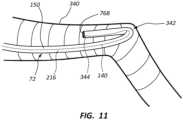
- FIG. 11depicts a scenario where optical modality of the system 10 can assist a clinician in detecting a malposition scenario for the catheter 72 within the vasculature.
- the catheter tube 150is disposed within a vessel 340 of the patient 70 in such a way as to undesirably double back on itself and form a kink region 342. Such kinks are possible during insertion of the catheter 72 into the body.
- the optical fiber 140including the plurality of FBG-type sensors 204, is also shown running along the length of the lumen defined by the catheter tube 150. Return optical signals from the sensors 204 in the kink region 342 during system operation will indicate the strain in the optical fiber 140 caused by the kink.
- information relating to the kinkcan be communicated to the clinician via the display 30 or by other suitable means.
- the cliniciancan view the catheter tube doubling back on itself as depicted on the display. Once the kink condition has been identified, the clinician can correct the kink and proceed with catheter insertion.
- FIG. 11further shows an obstruction 344, such as a thrombus or fibrin sheath, present proximate the distal end 76B of the catheter tube 150.
- an obstruction 344such as a thrombus or fibrin sheath
- Such obstructionsare also detectable by sensors 204 of the optical fiber 140 as part of the optical modality of the system 10. Once the obstruction condition has been communicated to the clinician, corrective measures may be undertaken to clear the obstruction from the catheter tube 150.
- optical fiber-based sensorscan be employed to confirm that a previously inserted catheter assembly (or other medical device) is still positioned as desired within the body of the patient. In one embodiment, this is achieved by feeding a stylet including an optical fiber-based series of strain sensors distally within a lumen of the catheter until reaching the distal tip of the catheter. Strain and other measurements may then be performed by the sensors disposed within the catheter lumen, thus enabling the system with which the sensors are operably connected to determine the shape, orientation, and position of the catheter tube within the vasculature of the patient, including the termination point of the catheter distal tip. This enables a clinician to ensure the catheter is still positioned at the desired location.
- the optical modality described hereincan detect and communicate other information to the clinician via the system 10 using the data provided by the sensor interrogation by the outgoing optical signals and the resultant return optical signals.
- informationincludes temperature, pressure, stiffness, strength, operational load on the catheter tube, liquid level within the lumen 14, blood oxygen level, magnetic field presence, etc.
- other conditions relating to the catheterincluding malposition/misdirection during catheter advancement including contralateral and IJ placement, arterial vs. venous placement, venous pressure and core body temperature, confirmation of the catheter staying within the true lumen of the vein or other vessel in the case of navigation through chronic total occlusion or other vessel blockage scenarios, etc.
Landscapes
- Health & Medical Sciences (AREA)
- Life Sciences & Earth Sciences (AREA)
- Engineering & Computer Science (AREA)
- Physics & Mathematics (AREA)
- General Health & Medical Sciences (AREA)
- Biomedical Technology (AREA)
- Heart & Thoracic Surgery (AREA)
- Animal Behavior & Ethology (AREA)
- Public Health (AREA)
- Veterinary Medicine (AREA)
- Surgery (AREA)
- Biophysics (AREA)
- Medical Informatics (AREA)
- Molecular Biology (AREA)
- Pathology (AREA)
- Nuclear Medicine, Radiotherapy & Molecular Imaging (AREA)
- General Physics & Mathematics (AREA)
- Radiology & Medical Imaging (AREA)
- Pulmonology (AREA)
- Anesthesiology (AREA)
- Hematology (AREA)
- Gynecology & Obstetrics (AREA)
- Human Computer Interaction (AREA)
- Robotics (AREA)
- Media Introduction/Drainage Providing Device (AREA)
- Endoscopes (AREA)
Description
- This application claims the benefit of
U.S. Provisional Application No. 62/483,195, filed April 7, 2017 US 2009/0137952 A1 discloses robotic medical instrument systems and associated methods utilizing an optical fiber sensors such as Bragg sensor optical fibers.US 2016/0228199 A1 discloses a shape sensing enabled instrument including a flexible longitudinal body including an outer surface which encapsulates interior features.WO 01/33165 A1 US 2008/0212082 A1 discloses a fiber optic position and/or shape sensing device including an optical fiber with either two or more single core optical fibers or a multi-core optical fiber having two or more fiber cores.- Briefly summarized, embodiments of the present invention are directed to a placement system for tracking, placing, and monitoring a catheter assembly or other medical device inserted into a body of a patient. The placement system utilizes optical fiber-based strain sensors to ascertain information regarding the catheter assembly during and/or after insertion into the patient's body.
- The invention is set out in the appended set of claims.
- Features of embodiments of the present invention will become more fully apparent from the following description and appended claims, or may be learned by the practice of embodiments of the invention as set forth hereinafter.
- A more particular description of the present disclosure will be rendered by reference to specific embodiments thereof that are illustrated in the appended drawings. It is appreciated that these drawings depict only typical embodiments of the invention and are therefore not to be considered limiting of its scope. Example embodiments of the invention will be described and explained with additional specificity and detail through the use of the accompanying drawings in which:
FIGS. 1A and 1B are various block diagram views of a placement system for guiding and placing a medical device into a body of a patient;FIG. 2 is a simplified view of a patient and the placement system ofFIGS. 1A and 1B ;FIG. 3 is a perspective view of a catheter assembly including an optical fiber-based sensor assembly;FIG. 4 is a side view of a portion of a catheter tube of the catheter assembly ofFIG. 3 ;FIG. 5 is a cross sectional view of a catheter tube;FIG. 6 is a cross sectional view of a catheter tube and a stylet inserted therein;FIG. 7 is a cross sectional view of an optical fiber with a single sensor position region;FIG. 8 is a cross sectional view of an optical fiber with multiple sensor positions;FIG. 9 is a perspective view of a stylet;FIGS. 10A-10C depict various screenshots of the placement system ofFIGS. 1A and 1B ; andFIG. 11 is a cross sectional view of a vessel of a body of a patient with a catheter tube disposed therein.- Reference will now be made to figures wherein like structures will be provided with like reference designations. It is understood that the drawings are diagrammatic and schematic representations of exemplary embodiments of the present invention, and are neither limiting nor necessarily drawn to scale.
- For clarity it is to be understood that the word "proximal" refers to a direction relatively closer to a clinician using the device to be described herein, while the word "distal" refers to a direction relatively further from the clinician. For example, the end of a catheter placed within the body of a patient is considered a distal end of the catheter, while the catheter end remaining outside the body is a proximal end of the catheter. Also, the words "including," "has," and "having," as used herein, including the claims, shall have the same meaning as the word "comprising."
- The present invention is defined by the medical device placement system as recited in
Claim 1. Preferred optional features are recited in the dependent claims. Embodiments of the present invention are generally directed to a placement system for tracking, placing, and monitoring a medical device inserted into a body of a patient. An example of such a medical device is a catheter assembly that is inserted into a vein or other vessel of the patient so as to infuse or aspirate fluids through one or more lumens defined by the catheter for the patient. The system utilizes optical fiber-based strain sensors in one embodiment to ascertain information regarding the catheter or other medical device during and/or after insertion into the patient's body. - In one embodiment, the strain sensors include fiber Bragg grating ("FBG") sensors distributed along an optical fiber disposed in/on the catheter assembly (or other medical device). An outgoing optical signal produced by a swept laser is incident on each of the FBG sensors in the fiber, which each respond, producing a return optical signal. A processor of the placement system processes the return optical signal with predetermined algorithms to determine the strain and other data of each of the FBG sensors. The data is communicated to a user of the system and can provide information regarding the medical device, its position within the body, the 2-D and 3-D shape of the medical device along its length (e.g., bending, torsion), device orientation (including malposition or device kinking), body temperature, fluid level within the medical device, device pressure, stiffness, and operational load, etc. Such information is presented by the system to the user in real-time to assist in guiding and placing the medical device as desired within the patient. Additionally, measurements may be made by the system post-placement to ensure the medical device is functional and properly placed by interrogating the FBG sensors anew. Further details regarding these and other embodiments are given hereafter.
- Note that, though the below discussion focuses on the placement of a catheter assembly into the body of the patient, the placement system described herein can be employed to place a variety of medical devices and components including other elongate and non-elongate medical devices in a variety of locations within the patient body. As such, the principles of the present disclosure should not be considered limiting to what is explicitly described herein. Examples of catheter assemblies and medical devices that may benefit from the present disclosure include a peripherally-inserted central catheter ("PICC"), central venous catheter ("CVC"), urinary catheter, midline catheter, peripheral catheter, an ECG lead, a needle, an NG tube, etc.
- In light of the above, the optical fiber-based strain sensor system described above thus serves as one modality in the above-introduced medical device placement system for guiding and placing a medical device within the body of a patient. As such, this modality if also referred to herein as an "optical modality." Note however that the placement system can also employ additional modalities for improving medical device placement accuracy, in addition to the optical modality introduced above and described in further detail below. In one embodiment an additional ultrasound ("US") modality is also employed by the system to enable ultrasound-assisted guidance for introducing a catheter assembly (or other medical device) into the patient's vasculature. After such introduction to the vasculature, the optical modality to be described herein can thereafter be employed to guide the catheter assembly to a desired location within the vasculature. These modalities are described in further detail below. In one embodiment, the optical modality alone is employed by the system.
- In yet another embodiment, additional modalities may be employed by the system to assist in guiding a catheter assembly (or other medical device) to a desired destination within the body of the patient. These include a tip location/navigation system ("TLS") modality, wherein magnetically-based tracking of the catheter tip during its advancement through the tortuous vasculature path is employed to detect and facilitate correction of any tip malposition during such advancement; and an ECG modality, wherein ECG signal-based catheter tip guidance is employed to enable tracking and guidance of the catheter tip to a desired position with respect to a node of the patient's heart from which the ECG signals originate. Such ECG-based positional assistance is also referred to as "tip confirmation." Further details regarding these modalities can be found in
U.S. Patent No. 8,781,555, filed March 2, 2010 , and titled System for Placement of a Catheter Including a Signal-Generating Stylet". - Use of the optical modality according to one embodiment enables the catheter placement system to facilitate catheter placement within the patient's vasculature with a relatively high level of accuracy, i.e., placement of the distal tip of the catheter in a predetermined and desired position. In one example implementation, use of the optical modality may result in correct tip placement being confirmed without the need for a confirmatory X-ray. This, in turn, reduces the patient's exposure to potentially harmful x-rays, the cost and time involved in transporting the patient to and from the x-ray department, costly and inconvenient catheter repositioning procedures, etc.
- Reference is first made to
FIGS. 1A-2 , which depict various components of a placement system ("system"), generally designated at 10, configured in accordance with one example embodiment of the present invention. As shown, thesystem 10 generally includes aconsole 20,display 30,probe 40, andoptical module 50, each of which is described in further detail below. FIG. 2 shows the general relation of these components to a patient 70 during a procedure to place acatheter 72 into the patient vasculature through askin insertion site 73.FIG. 2 shows that thecatheter 72 generally includes aproximal portion 74 that generally remains exterior to the patient and adistal potion 76 that generally resides within the patient vasculature after placement is complete. Thesystem 10 is employed to ultimately position a distal tip 76A of thecatheter 72 in a desired position within the patient vasculature. In one embodiment, the desired position for the catheter distal tip 76A is proximate the patient's heart, such as in the lower one-third (1/3rd) portion of the Superior Vena Cava ("SVC"). Of course, thesystem 10 can be employed to place the catheter distal tip in other locations. The catheterproximal portion 74 further includes abifurcation hub 74A that provides fluid communication between the one or more lumens of thecatheter 72 and one ormore extension legs 74B extending proximally from the bifurcation hub. Note that the bifurcation hub can include one, two, or more fluid paths to fluidly connect the catheter lumens with thecorresponding extension legs 74B.- An example implementation of the
console 20 is shown inFIG. 2 , though it is appreciated that the console can take one of a variety of forms.FIG. 1A shows that aprocessor 22, including non-volatile memory such as EEPROM for instance, is included in theconsole 20 for controlling system function during operation of thesystem 10, thus acting as a control processor. A digital controller/analog interface 24 is also included with theconsole 20 and is in communication with both theprocessor 22 and other system components to govern interfacing between theprobe 40,optical module 50, and other system components. - The
system 10 further includesports 52 for connection with theoptical module 50 andoptional components 54 including a printer, storage media, keyboard, etc. The ports in one embodiment are USB ports, though other port types or a combination of port types can be used for this and the other interfaces connections described herein. Apower connection 56 is included with theconsole 20 to enable operable connection to anexternal power supply 58. Aninternal battery 60 can also be employed, either with or exclusive of an external power supply.Power management circuitry 59 is included with the digital controller/analog interface 24 of the console to regulate power use and distribution. - The
display 30 in the present embodiment is integrated into theconsole 20 and is employed as a user interface to display information to the clinician during the catheter placement procedure. In another embodiment, the display may be separate from the console. As will be seen, the content depicted by thedisplay 30 changes according to which mode the catheter placement system is in: optical, US, or other modality. In one embodiment, aconsole button interface 32 and buttons included on theprobe 40 can be used to immediately call up a desired mode to thedisplay 30 by the clinician to assist in the placement procedure. In one embodiment, information from multiple modes, such as optical and US, may be displayed simultaneously. Thus, thesingle display 30 of thesystem console 20 can be employed for ultrasound guidance in accessing a patient's vasculature and optical modality-based guidance during catheter advancement through the vasculature. In one embodiment, thedisplay 30 is an LCD device. - The
probe 40 is employed in connection with the first modality mentioned above, i.e., ultrasound ("US")-based visualization of a vessel, such as a vein, in preparation for insertion of thecatheter 72 into the vasculature. Such visualization gives real time ultrasound guidance for introducing the catheter into the vasculature of the patient and assists in reducing complications typically associated with such introduction, including inadvertent arterial puncture, hematoma, pneumothorax, etc. - The
handheld probe 40 includes a head that houses a piezoelectric array for producing ultrasonic pulses and for receiving echoes thereof after reflection by the patient's body when the head is placed against the patient's skin proximate the prospective insertion site 73 (FIG. 2 ). Theprobe 40 further includes a plurality of control buttons, which can be included on a button pad. In the present embodiment, the modality of thesystem 10 can be controlled by the control buttons, thus eliminating the need for the clinician to reach out of the sterile field, which is established about the patient insertion site prior to catheter placement, to change modes via use of theconsole button interface 32. - As such, in one embodiment a clinician employs the first (US) modality to determine a suitable insertion site and establish vascular access, such as with a needle or introducer, then with the catheter. The clinician can then seamlessly switch, via button pushes on the
probe button pad 82, to the optical modality without having to reach out of the sterile field. Again, the optical modality can be used to assist in advancement of thecatheter 72 through the vasculature toward an intended destination. FIG. 1 shows that theprobe 40 further includes button andmemory controller 42 for governing button and probe operation. The button andmemory controller 42 can include non-volatile memory, such as EEPROM, in one embodiment. The button andmemory controller 42 is in operable communication with aprobe interface 44 of theconsole 20, which includes a piezo input/output component 44A for interfacing with the probe piezoelectric array and a button and memory input/output component 44B for interfacing with the button andmemory controller 42.- The
handheld ultrasound probe 40 is employed to enable US visualization of the peripheral vasculature of a patient in preparation for transcutaneous introduction of the catheter. In the present example embodiment, however, the probe is also employed to control functionality of other modalities of thesystem 10, including the optical modality, when navigating the catheter toward its desired destination within the vasculature as described below. Again, as theprobe 40 is used within the sterile field of the patient, this feature enables functionality of any one of the modalities to be controlled entirely from within the sterile field. Thus theprobe 40 is a multi-purpose device, enabling convenient control of both US and other modality functionality of thesystem 10 from the sterile field. Note that additional or fewer components can be included with thesystem 10 than what is shown and described herein. - As mentioned, the
system 10 includes theoptical module 50, which is shown in further detail ionFIG. 1B . As shown, theoptical module 50 includes an optical transmitter, such as alaser 80, configured to produce outgoing optical signals incident on a plurality of optical fiber-based strain sensors (described further below) of the catheter assembly. Theoptical module 50, as well as an optical receiver, such as aphotodetector 82, configured to receive return optical signals from the optical fiber-based strain sensors of the catheter assembly. In one embodiment, thelaser 80 is a tunable swept laser and both thelaser 80 and thephotodetector 82 are operably connected to theprocessor 22 of the system 10 (FIG. 1A ), which governs their operation. In another embodiment, another suitable light source can also be employed in addition to a laser, including semi-coherent light sources, LED light sources, etc. FIG. 1A also shows that the optical module in the present embodiment is operably connected to astylet 130, which includes an optical fiber and the plurality of strain sensors, as will be described further below. Thestylet 130 is configured to be removably received within thecatheter 72 during the procedure to place the catheter into the vasculature of the patient and enable thesystem 10 to guide the catheterdistal tip 76B to a desired destination within the body. Note, however, that the optical fiber and strain sensors can be configured in other ways other than a stylet, some of which are discussed further below. Note further that theoptical module 50 can include other components and be included within thesystem 10 in other configurations apart from what is shown and described herein.FIG. 2 shows thestylet 130 in place within thecatheter 72 as the catheter is being inserted into the patient 70 with the assistance of thesystem 10.FIGS. 2 and 3 depict further details regarding thestylet 130 and thecatheter 72. As shown, thecatheter 72 includes anelongate catheter tube 150 defining one ormore lumens 216 extending between proximal and distal ends of the catheter tube, which are in communication with thecorresponding extension legs 74B via thebifurcation hub 74A, as described further above. In the illustrated embodiment thecatheter 72 includes twolumens 216 and twocorresponding extension legs 74B, though other numbers of lumens and extension legs are possible.Luer connectors 75 are included on the proximal ends of theextension legs 74B.- Along with
FIGS. 2 and 3 , reference is made toFIG. 9 , which together depict details regarding thestylet 130 and thecatheter 72. As shown, thestylet 130 is an elongate device and includes asystem connector 132 on itsproximal end 130A to enable the stylet to operably connect with the console 20 (FIG. 2 ) or other suitable component of thesystem 10 via a threading (or other suitable) engagement. Atether 134 distally extends between thesystem connector 132 to acatheter connector 142 configured to threadably engage (or otherwise connect with) theluer connector 75 of one of theextension legs 74B of thecatheter 72, as seen inFIG. 3 . A fiber-bearingportion 138 of thestylet 130 extends distally from thecatheter connector 142 to adistal end 130B of the stylet. Ahandle 136 is included with thetether 134 to assist with manipulation of thestylet 130 by the user during system operation. - In greater detail, the fiber-bearing
portion 138 includes, as seen inFIG. 6 , anelongate core wire 138A with anoptical fiber 140 disposed in a longitudinal notch defined along an outer surface thereof. So configured, thecore wire 138A andoptical fiber 140 extend distally from thecatheter connector 142 to the distal end of the stylet 130 (FIG. 9 ). Theoptical fiber 140 is secured within the notch of thecore wire 138A by potting 214 (such as an adhesive), or by other suitable mode. Thecore wire 138A includes a suitable, flexible material, including stainless steel for instance.FIG. 6 shows the fiber-bearingportion 138 disposed in alumen 216 defined by awall 210 of a single-lumen catheter tube 150, though it is appreciated that the size, shape, and other configuration of the fiber-bearingportion 138 can vary from what is shown and described herein in order to accommodate catheters, lumens, and medical devices of differing configurations. - As shown in
FIG. 2 , thestylet 130 is inserted into thecatheter 72 during use of thesystem 10 to place thecatheter 72 in the body of thepatient 70. Thestylet 130 is shown with the fiber-bearingportion 138 disposed in the lumen of thecatheter 72 and thetether 134 extending from the fiber-bearing portion to theconsole 20 such that the stylet is operably connected to the system 10 (via the stylet system connector 132). In this way, outgoing optical signals produced by the laser 80 (FIG. 1B ) of theoptical module 50 and return optical signals to be received by thephotodetector 82 can travel to and from the optical fiber 140 (FIG. 6 ) and its corresponding strain sensors, as will be discussed further below. FIG. 3 depicts the manner of operable connection of the stylet with thecatheter 72. As shown, the fiber-bearingportion 138 is disposed within one of thelumens 216 of thecatheter tube 150 such that the distal end of thestylet 130B - and the distal end of the fiber-bearing portion and accompanying optical fiber 140 - is substantially co-terminal with thedistal tip 76B of the catheter. The fiber-bearingportion 138 extends proximally up thelumen 216, through thebifurcation hub 74A and corresponding extension leg 74Bto thecatheter connector 142, which is shown threadably attached to theluer connector 75 of the extension leg. Thetether 134 is further shown extending from thecatheter 72 to operably connect with theconsole 20, as shown inFIG. 2 . This connective configuration is used during the procedure to insert thecatheter 72 into the body of thepatient 70, and in one embodiment the stylet is pre-loaded into the catheter during time of catheter manufacture or prior to commencement of the insertion procedure. It is appreciated that thestylet 130, the fiber-bearingportion 138, and theoptical fiber 140 can be configured in other ways while still enabling the desired functionality of thesystem 10 to be performed. In yet another embodiment, theoptical fiber 140 need not be substantially co-terminal with thedistal tip 76B of thecatheter 72, but can terminate proximal or distal thereto, as may be appreciated by one skilled in the art. As will be seen, the strain sensors of theoptical fiber 140 included with the fiber-bearingportion 138 of thestylet 130 enable thecatheter 72 to be tracked during its advancement through the patient vasculature.- Note further that, though described herein as a stylet, in other embodiments a guidewire or other catheter guiding apparatus could include the components and functionality described herein. Indeed, it should appreciated that "stylet" as used herein can include any one of a variety of devices configured for removable placement within a lumen of the catheter (or other portion of a medical device) to assist in placing a distal end of the catheter in a desired location within the patient's vasculature. Also, note that other connection schemes between the
stylet 130 and thesystem 10/console 20 can also be used without limitation. - Note that a sterile drape is often positioned over the patient 70 during the catheter insertion procedure in order to define the majority of a sterile field: areas above the drape are sterile, while areas below (excluding the insertion site and immediately surrounding region) are non-sterile. For instance, areas and components above the drape and proximate to the insertion site 73 (including the
catheter 72, thestylet 130, and tether 134) are included in the sterile field, while areas and components below the drape, including the patient's chest and regions immediately surrounding the patient 70 are considered a non-sterile field. In cases where thetether 134 of thestylet 130 needs to penetrate the drape in order to pass between the sterile and non-sterile fields, suitable connection nodes can be included with the stylet in order to pierce the drape while not compromising the sterile field.U.S. Patent No. 8,781 ,555 includes various examples of drape-piercing embodiments that can be employed to enable the stylet to acceptably pass through the drape while still enabling outgoing and return optical signals, as well as other signals, to pass between theoptical fiber 140 and theconsole 20. FIG. 4 generally depicts a portion, orstructure 100, of thecatheter tube 150 of thecatheter 72 to depict the spatial relationship between the catheter tube and the strain sensors included with theoptical fiber 140 discussed above. As shown, thestructure 100 is subdivided into a plurality of sections 202 (also designated with γi (i = 0, 1, 2, 3, ... n) such that the sections are designated as γ0, γ1, ..., γn), each section having a length Δl, whereinstrain sensors 204 are positioned at the junction of eachadjacent section 202, as well as at the beginning and end of the sections, designated inFIG. 4 as x;, thus at x0, x1 ..., xn. Thestrain sensors 204 are positioned a distance c from a neutral axis of 206 of thecatheter tube 150. When operative, thestrain sensors 204 are capable of each detecting a corresponding strain ε such that strain ε0 is detected atstrain sensor 204 positioned at x0 at the junction for section γ0, etc. U.S. Patent No. 7, 715, 994 gives further details regarding the strain sensors and their spatial distribution as depicted inFIG. 4 .FIG. 7 shows that, in one embodiment, a predeterminedsensor position region 220 is defined within theoptical fiber 140, wherein thesensors 204 are disposed along the longitudinal length of the optical fiber. In another embodiment, multiplesensor position regions 220 can be defined within the singleoptical fiber 140, as shown inFIG. 8 , for instance, such that distinct series, or channels, of strain or other sensors can be included on a single optical fiber. These multiple, non-colinear channels of strain sensors can be employed for differing purposes, such as one or more series to indicate medical device position with another series to monitor temperature along the medical device, for instance. These and other strain sensor position configurations with the optical fiber are therefore contemplated.- The
strain sensors 204 in one embodiment can be included with an optical fiber that is in turn included in a fiber-bearing of a stylet, such as thestylet 130 described above in connection withFIGS. 3 ,6 , and9 . Thestrain sensors 204 are included with an optical fiber that is permanently incorporated into thecatheter tube 150, such as is seen inFIG. 5 . Many other possible strain sensor implementations are possible, including other types of fiber optic sensors. - In the present embodiment, the
strain sensors 204 are configured as fiber Bragg grating ("FBG") sensors. The FBG sensors 34 are each configured to detect strain of the optical fiber at each sensor location, thus enabling the shape and movement of the optical fiber, and thus thecatheter tube 150 with which it is included, to be detected and determined as the catheter is inserted into the body of thepatient 70, as explained immediately below. - In greater detail, once the
catheter 72 has been introduced into the patient vasculature via the insertion site 73 (FIG. 1 ) the optical modality of thesystem 10 can be employed to advance the catheter distal tip 76A toward its intended destination proximate the SA node, in the current embodiment, noting that other intended destinations are also possible. Thecatheter 72 carries within one of itslumens 216 thestylet 130 including the fiber-bearingportion 138, which in turn includes theoptical fiber 140 with its strain sensors 204 (e.g., the FBG sensors in the present embodiment). As the stylet-loadedcatheter 72 is advanced toward the patient's heart, outgoing optical signals are produced by thelaser 80 of the optical module 50 (FIGS. 1A, 1B ), which optical signals propagate distally through theoptical fiber 140 via thestylet tether 134 to interrogate each of the FBG-type sensors 204, resulting in return optical signals from the sensors. The return optical signals from the FBG-type sensors 204 are received by thephotodetector 82 of the optical module after travelling proximally through theoptical fiber 140 and thestylet tether 134, which are then forwarded to theprocessor 22. The outgoing optical signal interrogation and return optical signal process is iterated at a scan rate to provide real-time monitoring. In one embodiment scan rates of 24 scans per second are employed, though other rates are possible. Specified algorithms and processes are followed to determine from the return optical signals the strain data from each of the FBG-type sensor 204. Further information regarding the algorithms and processes referred to immediately above, including serial multiplexing, suitable wavelength division multiplexing ("WDM"), and optical frequency domain reflectometry ("OFDM") processes with regard to a fiber optic sensing system ("F.O.S.S.") is described in:U.S. Patent No. 7,520,176 ;U.S. Patent No. 7,715,994 ;U.S. Patent No. 8,700,358 ; andU.S. Patent No. 8,909,040 . - In one example and in light of the above, therefore, a method for placing a catheter assembly (or other medical device) into a body of a patient includes stages: propagating an outgoing optical signal to a plurality of optical fiber-based strain sensors included with the catheter assembly; receiving a return optical signal from the strain sensors; and processing the return optical signal received from the strain sensors to derive data relating to the medical device. These stages are successively repeated while inserting the catheter assembly into the body of the patient so as to guide the catheter assembly to its intended destination.
- This above-described process results in specified strain data to be correlated along the sensor-equipped length of the
optical fiber 140. In turn, given the disposal of theoptical fiber 140 within thelumen 216 of thecatheter tube 150, the strain data enables information regarding the two- and three-dimensional shape of thecatheter tube 150 within the patient of the patient 70 to be ascertained, given that the detected strain-related displacement, bending, pressure, and torsion/twisting of theoptical fiber 140 correlates to the catheter tube itself in which the optical fiber is disposed. This and other informational aspects relating to the data collected from thesensors 204 can be communicated to the user of thesystem 1, via thedisplay 30 and/or other suitable user interface mode, to assist the user in knowing the location, orientation and shape of thecatheter 72 within the patient vasculature, thus enabling the user to advance the catheter distally and position thedistal tip 76B of the catheter in a desired location therein, in part by the fact that the distal end of the sensor-equippedoptical fiber 140 is substantially co-terminal with the distal tip of the catheter within the vasculature, in the present embodiment. The process of sending and receiving outgoing and return optical signals, respectively, occurs iteratively during system operation such that position, orientation, and shape information relating to thecatheter 72 is continuously received by the user via thesystem 10 during the catheter placement procedure. - Once it has been positioned as desired using the
system 10 as just described, thecatheter 72 may be secured in place and thestylet 130 removed from the catheter lumen. It is noted here that the stylet may include one of a variety of configurations in addition to what is explicitly described herein. In one embodiment, the stylet can attach directly or indirectly to the console. In another embodiment, the optical fiber of the stylet can be integrated into the catheter structure itself, thus eliminating the need for the stylet in bearing the optical fiber and included strain sensors.FIG. 5 gives one example of such an embodiment, wherein thecatheter tube 150 includes first and secondoptical fibers tube wall 210 that defines thelumen 216. Apotting 214, such as an adhesive, is used to adhere theoptical fibers tube wall 210. One, two, or more optical fibers can be included in the catheter tube in this manner. Also, in one embodiment, the optical fiber can incorporated into the catheter wall itself, such as via a co-extrusion process, for instance. These and other variations are therefore contemplated. - Note that in one embodiment the
console 20 includes the electronic components, such as the processor 22 (FIG. 1 ), necessary to process the return optical signals received by thephotodetector 82 via thestylet 130 or other suitable structure including theoptical fiber 140 andsensors 204. In another embodiment, this functionality can be included in another system component including, for example, theoptical module 50. - In the present embodiment, the position, orientation, shape, and other information regarding the
catheter 72, as provided by the optical fiber-basedsensors 204 and as described above is communicated to the user of thesystem 10 to assist with placing thedistal tip 76B (or other portion of the catheter) at a desired location within the patient vasculature/body, such as the lower 1/3rd of the superior vena cava. In the present embodiment, such information is depicted on thedisplay 30, included on theconsole 20 as part of thesystem 10, though it can be configured in other ways as well, including as a separate component in one embodiment. As has been described further above, the functionality of thedisplay 30 can be controlled bycontrol buttons 84 included on the handheld probe 40 (FIGS. 1A ,2 ), thus eliminating the need for the clinician to reach out of the sterile field (such as touching thebutton interface 32 of the console 20) to change modes. Thus, in the present embodiment theprobe 40 is employed to also control some or all functionality of thesystem 10. Note that thebutton interface 32 or other input configurations can also be used to control system functionality. Also, in addition to thevisual display 30, aural information, such as beeps, tones, etc., can also be employed by the system to assist the clinician during catheter placement. Moreover, the buttons included on theprobe 40 and theconsole button interface 32 can be configured in a variety of ways, including the use of user input controls in addition to buttons, such as slide switches, toggle switches, electronic or touch-sensitive pads, etc. FIG. 10A shows anexample screenshot 318 as depicted on thedisplay 30 while thesystem 10 is in operation. Arepresentative body image 320 is shown. Other information is provided on thedisplay screenshot 318, including adepth scale indicator 324, status/action indicia 326, andicons 328 corresponding to thebutton interface 32 included on the console 20 (FIG. 1A ). Though theicons 328 in the present embodiment are simply indicators to guide the user in identifying the purpose of the corresponding buttons of thebutton interface 32, in another embodiment the display can be made touch-sensitive so that the icons themselves can function as button interfaces and can change according to the mode the system is in.- During initial startup and preparation for insertion of the
catheter 72 into the patient vasculature, the display screenshot may indicate "no signal," as seen inFIG. 10A , indicating that no data is being returned from thesensors 204 of theoptical fiber 140. InFIG. 10B , a distal portion of thecatheter 72 has been inserted into the body of thepatient 70, which is represented in thescreenshot 318 by a relatively short path oftravel 330 distal to a depicted insertion site 332 (which corresponds to theactual insertion site 73 ofFIG. 2 ) on thedisplay 30. A still-external portion 334 of the catheter is also shown on thescreenshot 318 ofFIG. 10B , proximal to the depictedinsertion site 332. Temperature-based differences as detected in data received from the return optical signals enables thesystem 10 to determine at which point along the length of theoptical fiber 140 thecatheter tube 150 has entered into thebody 70 of the patient in the present embodiment, thus enabling the system to depict the location of theinsertion site 332. In like manner, the internal path oftravel 330 and theexternal portion 334 can be depicted on the display. Aposition icon 314 is also depicted at the detected distal end of the sensor-equippedoptical fiber 140, corresponding to thedistal tip 76B of thecatheter 72, in the present embodiment. - In
FIG. 10C , thecatheter 72 has advanced proximate a desired position within the patient vasculature, i.e., proximate the lower 1/3rd portion of the SVC in the present embodiment, as indicated by theposition icon 314 on thescreenshot body image 320. This is indicated by the relatively longer internal path oftravel 330 with respect to theinsertion site 332. Thesystem 10 is further able to detect and depict any bends or changes in direction in the catheter via processing of the return optical signals from thevarious sensors 204 along the length of optical fiber disposed in one of thelumens 216 of the catheter tube 150 (FIG. 3 ). As such, position, shape, and orientation of thecatheter 72 is determined by thesystem 10 and communicated to the clinician via thedisplay 30, thus enabling the clinician to accurately guide the catheter to the desired position within the vasculature. - According to the invention, the mapping of the catheter as an image on the
body image 320 to indicate the actual location of thecatheter 72 within the actual body of thepatient 70 is enabled by knowledge of the insertion site of the catheter (i.e., a reference location) - here represented by theinsertion site 332 ofFIG. 10C , the length of the portion of the catheter found inside the patient body (represented by the internal portion of the catheter 330), and the shape/displacement of the catheter as detected by the optical fiber-basedsensors 204 disposed within the catheter. FIG. 11 depicts a scenario where optical modality of thesystem 10 can assist a clinician in detecting a malposition scenario for thecatheter 72 within the vasculature. As shown, thecatheter tube 150 is disposed within avessel 340 of the patient 70 in such a way as to undesirably double back on itself and form akink region 342. Such kinks are possible during insertion of thecatheter 72 into the body. Theoptical fiber 140, including the plurality of FBG-type sensors 204, is also shown running along the length of the lumen defined by thecatheter tube 150. Return optical signals from thesensors 204 in thekink region 342 during system operation will indicate the strain in theoptical fiber 140 caused by the kink. After processing by thesystem 10, information relating to the kink can be communicated to the clinician via thedisplay 30 or by other suitable means. In one example, for instance, the clinician can view the catheter tube doubling back on itself as depicted on the display. Once the kink condition has been identified, the clinician can correct the kink and proceed with catheter insertion.FIG. 11 further shows anobstruction 344, such as a thrombus or fibrin sheath, present proximate thedistal end 76B of thecatheter tube 150. Such obstructions are also detectable bysensors 204 of theoptical fiber 140 as part of the optical modality of thesystem 10. Once the obstruction condition has been communicated to the clinician, corrective measures may be undertaken to clear the obstruction from thecatheter tube 150.- It should be appreciated that the use of optical fiber-based sensors can be employed to confirm that a previously inserted catheter assembly (or other medical device) is still positioned as desired within the body of the patient. In one embodiment, this is achieved by feeding a stylet including an optical fiber-based series of strain sensors distally within a lumen of the catheter until reaching the distal tip of the catheter. Strain and other measurements may then be performed by the sensors disposed within the catheter lumen, thus enabling the system with which the sensors are operably connected to determine the shape, orientation, and position of the catheter tube within the vasculature of the patient, including the termination point of the catheter distal tip. This enables a clinician to ensure the catheter is still positioned at the desired location.
- In addition to strain, stress, and torsion measurements that enable the two- and three-dimensional shape, position, and orientation of the catheter or other medical device to be determined while in the patient body, the optical modality described herein can detect and communicate other information to the clinician via the
system 10 using the data provided by the sensor interrogation by the outgoing optical signals and the resultant return optical signals. Such information includes temperature, pressure, stiffness, strength, operational load on the catheter tube, liquid level within the lumen 14, blood oxygen level, magnetic field presence, etc. Further, it is appreciated that, in light of the above disclosure, other conditions relating to the catheter may be detected, including malposition/misdirection during catheter advancement including contralateral and IJ placement, arterial vs. venous placement, venous pressure and core body temperature, confirmation of the catheter staying within the true lumen of the vein or other vessel in the case of navigation through chronic total occlusion or other vessel blockage scenarios, etc.
Claims (8)
- A medical device placement system (10) for inserting an elongate medical device including a catheter (72) into a body of a patient (70) through a skin insertion site (73), comprising:a plurality of optical fiber-based strain sensors (204) configured to be included with the medical device;a light source (80) configured to operably connect with the plurality of strain sensors (204) and produce outgoing optical signals incident on the strain sensors (204);a photodetector (82) configured to operably connect with the plurality of strain sensors (204) and receive return optical signals from the strain sensors (204);a processor (22) configured to process data from the return optical signals, the data relating to an aspect of the medical device; anda user interface configured to communicate information relating to the aspect of the medical device,wherein the catheter (72) includes a proximal portion (74) that is configured to remain exterior to the patient (70), a distal portion (76) that is configured to reside within the patient (70) after placement is complete, and an elongate catheter tube (150) defining one or more lumens (216) extending between proximal and distal ends of the elongate catheter tube (150),wherein the proximal portion (74) includes a bifurcation hub (74A) that provides fluid communication between the one or more lumens (216) of the catheter (72) and one or more extension legs (74B) extending proximally from the bifurcation hub (74A),wherein the one or more lumens (216) are in communication with the corresponding extension legs (74B) via the bifurcation hub (74A),wherein the strain sensors (204) are distributed along a longitudinal length of an optical fiber (140),wherein the optical fiber (140) is permanently incorporated into the catheter tube (150),wherein the user interface includes a display (30),wherein the processor (22) is configured to cause the display (30) to include information relating to a position of the medical device within the body of the patient (70), wherein the information includes a representative body image (320), andwherein the processor (22) is configured to cause the display (30) to map the catheter (72) as an image on the body image (320) to indicate an actual location of the catheter (72) within the body of the patient (70) enabled by knowledge of the insertion site (73) of the catheter (72), a length of the distal portion (76) and a shape/displacement of the catheter (72) as detected by the strain sensors (204).
- The system as defined in claim 1, wherein the light source (80) is a laser and wherein the laser and the photodetector (82) are included in an optical module (50).
- The system as defined in claim 1 or 2, wherein the strain sensors (204) include fiber Bragg grating sensors (34).
- The system as defined in any one of claims 1-3, wherein the aspect of the medical device includes at least one of a two-dimensional and a three-dimensional shape of a portion of the catheter (72).
- The system as defined in any one of claims 1-4, wherein the processor (22) is configured to control functionality of the light source (80) and the photodetector (82).
- The system as defined in any one of claims 1-5, wherein the information relating to the aspect of the medical device is configured to assist a user of the system in guiding the medical device to a desired position within the body of the patient (70).
- The system as defined in any one of claims 1-6, wherein the light source (80) is configured to iteratively emit outgoing optical signals and wherein the photodetector (82) is configured to iteratively receive the return optical signals.
- The system as defined in any one of claims 1-7, wherein a first plurality of strain sensors (204) are included on a first longitudinal portion of an optical fiber (140), and wherein a second plurality of strain sensors (204) are included on a second longitudinal portion of the optical fiber (140), the first and second plurality of strain sensors (204) not co-linear with one another on the optical fiber (140).
Applications Claiming Priority (2)
| Application Number | Priority Date | Filing Date | Title |
|---|---|---|---|
| US201762483195P | 2017-04-07 | 2017-04-07 | |
| PCT/US2018/026493WO2018187708A1 (en) | 2017-04-07 | 2018-04-06 | Optical fiber-based medical device tracking and monitoring system |
Publications (4)
| Publication Number | Publication Date |
|---|---|
| EP3606592A1 EP3606592A1 (en) | 2020-02-12 |
| EP3606592A4 EP3606592A4 (en) | 2020-12-23 |
| EP3606592B1true EP3606592B1 (en) | 2025-01-08 |
| EP3606592C0 EP3606592C0 (en) | 2025-01-08 |
Family
ID=63710659
Family Applications (1)
| Application Number | Title | Priority Date | Filing Date |
|---|---|---|---|
| EP18781915.6AActiveEP3606592B1 (en) | 2017-04-07 | 2018-04-06 | Optical fiber-based medical device tracking and monitoring system |
Country Status (4)
| Country | Link |
|---|---|
| US (2) | US12140487B2 (en) |
| EP (1) | EP3606592B1 (en) |
| CN (1) | CN211884909U (en) |
| WO (1) | WO2018187708A1 (en) |
Families Citing this family (50)
| Publication number | Priority date | Publication date | Assignee | Title |
|---|---|---|---|---|
| ITUB20155218A1 (en)* | 2015-10-16 | 2017-04-16 | Alberto Micco | SYSTEM FOR GUIDING MEDICAL DEVICES |
| EP3606592B1 (en) | 2017-04-07 | 2025-01-08 | Bard Access Systems, Inc. | Optical fiber-based medical device tracking and monitoring system |
| US10992078B2 (en) | 2018-01-29 | 2021-04-27 | Bard Access Systems, Inc. | Connection system for establishing an electrical connection through a drape and methods thereof |
| EP3793464A4 (en) | 2018-05-18 | 2021-07-21 | Bard Access Systems, Inc. | CONNECTION SYSTEM AND METHOD FOR MAKING AN ELECTRICAL CONNECTION THROUGH A COVERING CLOTH |
| CN114174878B (en) | 2019-07-29 | 2024-07-30 | 巴德阿克塞斯系统股份有限公司 | Connection system and method for establishing optical and electrical connections through a drape |
| US12029498B2 (en) | 2019-08-08 | 2024-07-09 | Bard Access Systems, Inc. | Optical-fiber connector modules including shape-sensing systems and methods thereof |
| EP4013338A4 (en)* | 2019-08-12 | 2023-08-30 | Bard Access Systems, Inc. | SHAPE DETECTION SYSTEMS AND METHODS FOR MEDICAL DEVICES |
| US11759166B2 (en) | 2019-09-20 | 2023-09-19 | Bard Access Systems, Inc. | Automatic vessel detection tools and methods |
| CN112826497B (en)* | 2019-11-25 | 2025-09-09 | 巴德阿克塞斯系统股份有限公司 | Optical tip tracking system and method thereof |
| EP4061272A4 (en) | 2019-11-25 | 2023-11-22 | Bard Access Systems, Inc. | Shape-sensing systems with filters and methods thereof |
| US11474310B2 (en) | 2020-02-28 | 2022-10-18 | Bard Access Systems, Inc. | Optical connection systems and methods thereof |
| CN215461207U (en) | 2020-02-28 | 2022-01-11 | 巴德阿克塞斯系统股份有限公司 | Catheter and medical instrument monitoring system |
| CN113332561A (en) | 2020-03-03 | 2021-09-03 | 巴德阿克塞斯系统股份有限公司 | System and method for optical shape sensing and electrical signal conduction |
| CN214956033U (en)* | 2020-03-19 | 2021-11-30 | 巴德阿克塞斯系统股份有限公司 | Data acquisition module, data acquisition equipment and medical device monitoring system |
| WO2021202589A1 (en) | 2020-03-30 | 2021-10-07 | Bard Access Systems, Inc. | Optical and electrical diagnostic systems and methods thereof |
| CN113842536A (en)* | 2020-06-26 | 2021-12-28 | 巴德阿克塞斯系统股份有限公司 | Dislocation detection system |
| WO2022005870A1 (en)* | 2020-06-29 | 2022-01-06 | Bard Access Systems, Inc. | Automatic dimensional frame reference for fiber optic |
| WO2022011287A1 (en)* | 2020-07-10 | 2022-01-13 | Bard Access Systems, Inc. | Continuous fiber optic functionality monitoring and self-diagnostic reporting system |
| WO2022031613A1 (en)* | 2020-08-03 | 2022-02-10 | Bard Access Systems, Inc. | Bragg grated fiber optic fluctuation sensing and monitoring system |
| US11992363B2 (en) | 2020-09-08 | 2024-05-28 | Bard Access Systems, Inc. | Dynamically adjusting ultrasound-imaging systems and methods thereof |
| CN216257185U (en) | 2020-09-10 | 2022-04-12 | 巴德阿克塞斯系统股份有限公司 | Ultrasound Probes and Ultrasound Systems |
| CN114246583A (en) | 2020-09-25 | 2022-03-29 | 巴德阿克塞斯系统股份有限公司 | Fiber Optic Oximetry Systems for Detection and Confirmation |
| CN114344514A (en) | 2020-10-13 | 2022-04-15 | 巴德阿克塞斯系统股份有限公司 | Disinfection enclosure for fiber optic connectors and method thereof |
| CN114518075A (en)* | 2020-11-18 | 2022-05-20 | 巴德阿克塞斯系统股份有限公司 | fiber optic stylet holder |
| CN216933458U (en) | 2020-11-24 | 2022-07-12 | 巴德阿克塞斯系统股份有限公司 | Object recognition and needle guidance system |
| WO2022115624A1 (en)* | 2020-11-24 | 2022-06-02 | Bard Access Systems, Inc. | Steerable fiber optic shape sensing enabled elongated medical instrument |
| CN114569156A (en) | 2020-12-01 | 2022-06-03 | 巴德阿克塞斯系统股份有限公司 | Ultrasound imaging system and method for identifying one or more of a plurality of blood vessels |
| CN114569155A (en) | 2020-12-01 | 2022-06-03 | 巴德阿克塞斯系统股份有限公司 | Ultrasound imaging system and method for obtaining ultrasound image by the same |
| WO2022150411A1 (en) | 2021-01-06 | 2022-07-14 | Bard Access Systems, Inc. | Needle guidance using fiber optic shape sensing |
| US12426954B2 (en)* | 2021-01-26 | 2025-09-30 | Bard Access Systems, Inc. | Fiber optic shape sensing system associated with port placement |
| CN217960146U (en) | 2021-04-15 | 2022-12-06 | 巴德阿克塞斯系统股份有限公司 | Ultrasound imaging system |
| CN217960085U (en)* | 2021-05-18 | 2022-12-06 | 巴德阿克塞斯系统股份有限公司 | Medical device system for detecting placement of a medical device within a patient's body |
| CN115868960A (en)* | 2021-09-27 | 2023-03-31 | 巴德阿克塞斯系统股份有限公司 | Medical device shape filtering system and method |
| CN115886783A (en)* | 2021-09-30 | 2023-04-04 | 巴德阿克塞斯系统股份有限公司 | Shape sensing reference frame |
| US12419694B2 (en)* | 2021-10-25 | 2025-09-23 | Bard Access Systems, Inc. | Reference plane for medical device placement |
| CN116058873A (en) | 2021-11-03 | 2023-05-05 | 巴德阿克塞斯系统股份有限公司 | Interoperation optimization function through Doppler and image-based vessel discrimination |
| US12318149B2 (en) | 2022-03-08 | 2025-06-03 | Bard Access Systems, Inc. | Medical shape sensing devices and systems |
| US12433567B2 (en) | 2022-03-16 | 2025-10-07 | Bard Access Systems, Inc. | Ultrasound imaging system |
| US12426956B2 (en) | 2022-03-16 | 2025-09-30 | Bard Access Systems, Inc. | Medical system and method for monitoring medical device insertion and illumination patterns |
| US12089815B2 (en)* | 2022-03-17 | 2024-09-17 | Bard Access Systems, Inc. | Fiber optic medical systems and devices with atraumatic tip |
| US20230346482A1 (en)* | 2022-04-27 | 2023-11-02 | Bard Access Systems, Inc. | Conductor Incorporated Fiber Enabled Medical Systems |
| US20230346314A1 (en) | 2022-04-27 | 2023-11-02 | Bard Access Systems, Inc. | Steerable Devices for Fiber Enabled Medical Systems |
| CN115025367A (en)* | 2022-04-29 | 2022-09-09 | 南京航空航天大学 | IPMC-based adaptive micro-catheter guiding device |
| US12343117B2 (en) | 2022-06-28 | 2025-07-01 | Bard Access Systems, Inc. | Fiber optic medical systems and methods for identifying blood vessels |
| US12349984B2 (en)* | 2022-06-29 | 2025-07-08 | Bard Access Systems, Inc. | System, method, and apparatus for improved confirm of an anatomical position of a medical instrument |
| US20240016425A1 (en)* | 2022-07-12 | 2024-01-18 | Bard Access Systems, Inc. | Eccentric Single-Core Fiber-Optic Enabled Medical Device |
| US20240065673A1 (en)* | 2022-08-24 | 2024-02-29 | Bard Access Systems, Inc. | Ultrasound Smart Port Accessory |
| WO2024064334A1 (en) | 2022-09-23 | 2024-03-28 | Bard Access Systems, Inc. | Automated measurement system |
| US20240226504A1 (en)* | 2023-01-10 | 2024-07-11 | Bard Access Systems, Inc. | Adjustable Elongate Medical Device Handle |
| WO2025166005A1 (en)* | 2024-02-02 | 2025-08-07 | Arizona Board Of Regents On Behalf Of Arizona State University | Apparatus and method for determining positional information of intra-body steerable assembly |
Family Cites Families (250)
| Publication number | Priority date | Publication date | Assignee | Title |
|---|---|---|---|---|
| IL78756A0 (en) | 1986-05-12 | 1986-08-31 | Biodan Medical Systems Ltd | Catheter and probe |
| JP2722132B2 (en) | 1989-05-03 | 1998-03-04 | 日機装株式会社 | Device and method for alleviating stenosis from the lumen |
| CN1049287A (en) | 1989-05-24 | 1991-02-20 | 住友电气工业株式会社 | The treatment conduit |
| US5163935A (en) | 1991-02-20 | 1992-11-17 | Reliant Laser Corporation | Surgical laser endoscopic focusing guide with an optical fiber link |
| CA2104960C (en) | 1991-02-26 | 2005-04-05 | Richard P. Rava | Systems and methods of molecular spectroscopy to provide for the diagnosis of tissue |
| JPH06509963A (en) | 1991-08-28 | 1994-11-10 | メドトロニック インコーポレーテッド | Operable stylet and operation handle assembly |
| US5211165A (en) | 1991-09-03 | 1993-05-18 | General Electric Company | Tracking system to follow the position and orientation of a device with radiofrequency field gradients |
| US5275151A (en) | 1991-12-11 | 1994-01-04 | Clarus Medical Systems, Inc. | Handle for deflectable catheter |
| US5280786A (en) | 1992-01-21 | 1994-01-25 | Fiberoptic Sensor Technologies, Inc. | Fiberoptic blood pressure and oxygenation sensor |
| US5423321A (en) | 1993-02-11 | 1995-06-13 | Fontenot; Mark G. | Detection of anatomic passages using infrared emitting catheter |
| EP0700269B1 (en) | 1993-04-22 | 2002-12-11 | Image Guided Technologies, Inc. | System for locating relative positions of objects |
| US5454807A (en) | 1993-05-14 | 1995-10-03 | Boston Scientific Corporation | Medical treatment of deeply seated tissue using optical radiation |
| US6597941B2 (en) | 1994-09-15 | 2003-07-22 | Stryker Corporation | Transillumination of body members for protection during body invasive procedures |
| US5517997A (en) | 1994-09-15 | 1996-05-21 | Gabriel Medical, Inc. | Transillumination of body members for protection during body invasive procedures |
| US5740808A (en) | 1996-10-28 | 1998-04-21 | Ep Technologies, Inc | Systems and methods for guilding diagnostic or therapeutic devices in interior tissue regions |
| US5879306A (en) | 1996-06-13 | 1999-03-09 | Stryker Corporation | Infrared system for visualizing body members |
| US5904147A (en) | 1996-08-16 | 1999-05-18 | University Of Massachusetts | Intravascular catheter and method of controlling hemorrhage during minimally invasive surgery |
| US7603166B2 (en) | 1996-09-20 | 2009-10-13 | Board Of Regents University Of Texas System | Method and apparatus for detection of vulnerable atherosclerotic plaque |
| US6119031A (en) | 1996-11-21 | 2000-09-12 | Boston Scientific Corporation | Miniature spectrometer |
| US5872879A (en) | 1996-11-25 | 1999-02-16 | Boston Scientific Corporation | Rotatable connecting optical fibers |
| US6069698A (en) | 1997-08-28 | 2000-05-30 | Olympus Optical Co., Ltd. | Optical imaging apparatus which radiates a low coherence light beam onto a test object, receives optical information from light scattered by the object, and constructs therefrom a cross-sectional image of the object |
| US6175752B1 (en) | 1998-04-30 | 2001-01-16 | Therasense, Inc. | Analyte monitoring device and methods of use |
| US6081741A (en) | 1998-06-05 | 2000-06-27 | Vector Medical, Inc. | Infrared surgical site locating device and method |
| AU762236B2 (en) | 1998-06-09 | 2003-06-19 | Cardeon Corporation | Cardiovascular catheter apparatus and catheter positioning method using tissue transillumination |
| WO2000010456A1 (en) | 1998-08-02 | 2000-03-02 | Super Dimension Ltd. | Intrabody navigation system for medical applications |
| US6319227B1 (en) | 1998-08-05 | 2001-11-20 | Scimed Life Systems, Inc. | Automatic/manual longitudinal position translator and rotary drive system for catheters |
| WO2000019889A1 (en) | 1998-10-08 | 2000-04-13 | University Of Kentucky Research Foundation | Methods and apparatus for in vivo identification and characterization of vulnerable atherosclerotic plaques |
| US6178346B1 (en) | 1998-10-23 | 2001-01-23 | David C. Amundson | Infrared endoscopic imaging in a liquid with suspended particles: method and apparatus |
| US6615072B1 (en) | 1999-02-04 | 2003-09-02 | Olympus Optical Co., Ltd. | Optical imaging device |
| US6398721B1 (en) | 1999-02-19 | 2002-06-04 | Olympus Optical Co., Ltd. | Surgical microscope apparatus |
| US6208887B1 (en) | 1999-06-24 | 2001-03-27 | Richard H. Clarke | Catheter-delivered low resolution Raman scattering analyzing system for detecting lesions |
| US7935108B2 (en) | 1999-07-14 | 2011-05-03 | Cardiofocus, Inc. | Deflectable sheath catheters |
| DE60020566T2 (en) | 1999-07-30 | 2006-05-04 | Boston Scientific Ltd., St. Michael | CATHETER WITH DRIVE AND CLUTCH FOR TURNING AND LENGTH SHIFTING |
| US6299622B1 (en) | 1999-08-19 | 2001-10-09 | Fox Hollow Technologies, Inc. | Atherectomy catheter with aligned imager |
| US6687010B1 (en) | 1999-09-09 | 2004-02-03 | Olympus Corporation | Rapid depth scanning optical imaging device |
| US7366562B2 (en) | 2003-10-17 | 2008-04-29 | Medtronic Navigation, Inc. | Method and apparatus for surgical navigation |
| CA2325036A1 (en) | 1999-10-29 | 2001-04-29 | Advanced Sensor Technology, Llc | Optical fiber navigation system |
| US6685666B1 (en) | 1999-11-12 | 2004-02-03 | Mark G. Fontenot | Catheters for breast surgery |
| US6692430B2 (en) | 2000-04-10 | 2004-02-17 | C2Cure Inc. | Intra vascular imaging apparatus |
| US6650923B1 (en) | 2000-04-13 | 2003-11-18 | Ev3 Sunnyvale, Inc. | Method for accessing the left atrium of the heart by locating the fossa ovalis |
| US7231243B2 (en) | 2000-10-30 | 2007-06-12 | The General Hospital Corporation | Optical methods for tissue analysis |
| US20020115922A1 (en) | 2001-02-12 | 2002-08-22 | Milton Waner | Infrared assisted monitoring of a catheter |
| WO2002088684A1 (en) | 2001-04-30 | 2002-11-07 | The General Hospital Corporation | Method and apparatus for improving image clarity and sensitivity in optical coherence tomography using dynamic feedback to control focal properties and coherence gating |
| US7532920B1 (en) | 2001-05-31 | 2009-05-12 | Advanced Cardiovascular Systems, Inc. | Guidewire with optical fiber |
| US6701181B2 (en) | 2001-05-31 | 2004-03-02 | Infraredx, Inc. | Multi-path optical catheter |
| US7992573B2 (en)* | 2001-06-19 | 2011-08-09 | The Trustees Of The University Of Pennsylvania | Optically guided system for precise placement of a medical catheter in a patient |
| WO2002103409A2 (en) | 2001-06-19 | 2002-12-27 | The Trustees Of The University Of Pennsylvania | Optical guidance system for invasive catheter placement |
| JP4450622B2 (en) | 2001-09-28 | 2010-04-14 | アンジオ ダイナミクス インコーポレイテッド | Impedance-controlled tissue peeling device and method |
| US6895267B2 (en) | 2001-10-24 | 2005-05-17 | Scimed Life Systems, Inc. | Systems and methods for guiding and locating functional elements on medical devices positioned in a body |
| US20030092995A1 (en) | 2001-11-13 | 2003-05-15 | Medtronic, Inc. | System and method of positioning implantable medical devices |
| US6711426B2 (en) | 2002-04-09 | 2004-03-23 | Spectros Corporation | Spectroscopy illuminator with improved delivery efficiency for high optical density and reduced thermal load |
| AU2003258124A1 (en) | 2002-08-05 | 2004-02-23 | Miravant Medical Technologies | Light delivery catheter |
| WO2004012586A2 (en) | 2002-08-05 | 2004-02-12 | Infraredx, Inc. | Near-infrared spectroscopic analysis of blood vessel walls |
| US6892090B2 (en) | 2002-08-19 | 2005-05-10 | Surgical Navigation Technologies, Inc. | Method and apparatus for virtual endoscopy |
| AU2003263454A1 (en) | 2002-09-19 | 2004-04-08 | Petrus Besselink | Vascular filter with improved strength and flexibility |
| US7599730B2 (en) | 2002-11-19 | 2009-10-06 | Medtronic Navigation, Inc. | Navigation system for cardiac therapies |
| US7132645B2 (en) | 2003-03-07 | 2006-11-07 | Infraredx, Inc. | System and method for assessing catheter connection using return loss |
| JP4871121B2 (en) | 2003-03-07 | 2012-02-08 | コーニンクレッカ フィリップス エレクトロニクス エヌ ヴィ | Apparatus and method for locating an instrument in a body |
| DE10313868B4 (en) | 2003-03-21 | 2009-11-19 | Siemens Ag | Catheter for magnetic navigation |
| DE10323217A1 (en) | 2003-05-22 | 2004-12-16 | Siemens Ag | Optical coherent tomography system of examination of tissues or organs, has position sensor at tip of catheter and reconstructs volume image based on sectional images and associated position data |
| US7322953B2 (en) | 2003-08-04 | 2008-01-29 | Covidien Ag | Catheter device |
| US7840253B2 (en) | 2003-10-17 | 2010-11-23 | Medtronic Navigation, Inc. | Method and apparatus for surgical navigation |
| US8571640B2 (en) | 2003-12-11 | 2013-10-29 | The Regents Of The University Of California | Catheter based mid-infrared reflectance and reflectance generated absorption spectroscopy |
| DE10358735B4 (en) | 2003-12-15 | 2011-04-21 | Siemens Ag | Catheter device comprising a catheter, in particular an intravascular catheter |
| US7587236B2 (en) | 2004-01-08 | 2009-09-08 | Lawrence Livermore National Security, Llc | Optical spectroscopy for the detection of ischemic tissue injury |
| US20050261598A1 (en) | 2004-04-07 | 2005-11-24 | Triage Wireless, Inc. | Patch sensor system for measuring vital signs |
| US20050278010A1 (en) | 2004-05-27 | 2005-12-15 | Scimed Life Systems, Inc. | Stent delivery system with imaging capability |
| US7772541B2 (en)* | 2004-07-16 | 2010-08-10 | Luna Innnovations Incorporated | Fiber optic position and/or shape sensing based on rayleigh scatter |
| US20060013523A1 (en) | 2004-07-16 | 2006-01-19 | Luna Innovations Incorporated | Fiber optic position and shape sensing device and method relating thereto |
| US20080039715A1 (en) | 2004-11-04 | 2008-02-14 | Wilson David F | Three-dimensional optical guidance for catheter placement |
| US7918787B2 (en) | 2005-02-02 | 2011-04-05 | Voyage Medical, Inc. | Tissue visualization and manipulation systems |
| US11478152B2 (en) | 2005-02-02 | 2022-10-25 | Intuitive Surgical Operations, Inc. | Electrophysiology mapping and visualization system |
| US20060189959A1 (en)* | 2005-02-22 | 2006-08-24 | Schneiter James A | High flow diffusion catheter |
| US8182433B2 (en) | 2005-03-04 | 2012-05-22 | Endosense Sa | Medical apparatus system having optical fiber load sensing capability |
| DE102005012699A1 (en) | 2005-03-18 | 2006-09-28 | Siemens Ag | Medical imaging method for obtaining intravascular images involves performing imaging using optical coherence tomography (OCT) and light that can penetrate fabric, using OCT and light that can penetrate blood or using infrared camera |
| US9204830B2 (en) | 2005-04-15 | 2015-12-08 | Surgisense Corporation | Surgical instruments with sensors for detecting tissue properties, and system using such instruments |
| WO2006116701A2 (en) | 2005-04-28 | 2006-11-02 | Research Foundation Of The City University Of New York | Imaging systems and methods to improve backscattering imaging using circular polarization memory |
| US20070016069A1 (en) | 2005-05-06 | 2007-01-18 | Sorin Grunwald | Ultrasound sensor |
| US20090118612A1 (en) | 2005-05-06 | 2009-05-07 | Sorin Grunwald | Apparatus and Method for Vascular Access |
| US8644910B2 (en) | 2005-07-19 | 2014-02-04 | Biosensors International Group, Ltd. | Imaging protocols |
| US20070073160A1 (en) | 2005-09-13 | 2007-03-29 | Children's Medical Center Corporation | Light-guided transluminal catheter |
| US7930065B2 (en)* | 2005-12-30 | 2011-04-19 | Intuitive Surgical Operations, Inc. | Robotic surgery system including position sensors using fiber bragg gratings |
| US20070201793A1 (en)* | 2006-02-17 | 2007-08-30 | Charles Askins | Multi-core optical fiber and method of making and using same |
| JP5631585B2 (en) | 2006-03-22 | 2014-11-26 | コーニンクレッカ フィリップス エレクトロニクス エヌ.ヴィ. | Optical fiber equipment sensing system |
| US8187189B2 (en) | 2006-04-28 | 2012-05-29 | The Invention Science Fund I, Llc | Imaging via blood vessels |
| US9596994B2 (en) | 2006-06-02 | 2017-03-21 | J. William J. Futrell | System and methods for illuminating materials |
| US20080082004A1 (en) | 2006-09-08 | 2008-04-03 | Triage Wireless, Inc. | Blood pressure monitor |
| WO2008063621A2 (en) | 2006-11-21 | 2008-05-29 | Bridgepoint Medical, Inc. | Endovascular devices and methods for exploiting intramural space |
| US8073517B1 (en) | 2006-11-30 | 2011-12-06 | Dartmouth-Hitchcock Clinic | System and method for measuring blood constituents using a catheter |
| US7729735B1 (en) | 2006-11-30 | 2010-06-01 | Dartmouth-Hitchcock Clinic | System and method for venous oximetry using a catheter |
| US20080172119A1 (en) | 2007-01-12 | 2008-07-17 | Medtronic Vascular, Inc. | Prosthesis Deployment Apparatus and Methods |
| US20080183128A1 (en)* | 2007-01-24 | 2008-07-31 | John Morriss | Methods, devices and systems for treatment and/or diagnosis of disorders of the ear, nose and throat |
| US8700358B1 (en) | 2007-03-07 | 2014-04-15 | The United States Of America As Represented By The Administrator Of The National Aeronautics And Space Administration | Method for reducing the refresh rate of Fiber Bragg Grating sensors |
| WO2008131303A2 (en) | 2007-04-20 | 2008-10-30 | Hansen Medical, Inc. | Optical fiber shape sensing systems |
| US8622935B1 (en) | 2007-05-25 | 2014-01-07 | Endosense Sa | Elongated surgical manipulator with body position and distal force sensing |
| EP2178442B1 (en) | 2007-07-12 | 2017-09-06 | Volcano Corporation | Catheter for in vivo imaging |
| EP2626030A3 (en) | 2007-08-14 | 2017-03-08 | Koninklijke Philips N.V. | Robotic instrument systems and methods utilizing optical fiber sensors |
| ES2465915T3 (en) | 2007-11-26 | 2014-06-09 | C.R. Bard, Inc. | Integrated system for intravascular catheter placement |
| US9649048B2 (en)* | 2007-11-26 | 2017-05-16 | C. R. Bard, Inc. | Systems and methods for breaching a sterile field for intravascular placement of a catheter |
| US8781555B2 (en)* | 2007-11-26 | 2014-07-15 | C. R. Bard, Inc. | System for placement of a catheter including a signal-generating stylet |
| US9521961B2 (en)* | 2007-11-26 | 2016-12-20 | C. R. Bard, Inc. | Systems and methods for guiding a medical instrument |
| US9211160B2 (en) | 2008-01-16 | 2015-12-15 | Luiz Geraldo Pivotto | Remotely controlled catheter insertion system with automatic control system |
| US11123047B2 (en) | 2008-01-28 | 2021-09-21 | The General Hospital Corporation | Hybrid systems and methods for multi-modal acquisition of intravascular imaging data and counteracting the effects of signal absorption in blood |
| JP5069585B2 (en) | 2008-02-25 | 2012-11-07 | 富士フイルム株式会社 | Optical tomographic imaging system using an optical probe |
| EP2240111B1 (en) | 2008-06-18 | 2019-07-24 | Mako Surgical Corp. | Fiber optic tracking system |
| US20100030063A1 (en) | 2008-07-31 | 2010-02-04 | Medtronic, Inc. | System and method for tracking an instrument |
| JP5591239B2 (en) | 2008-08-28 | 2014-09-17 | コーニンクレッカ フィリップス エヌ ヴェ | Nutrition tube |
| EP2559533B1 (en) | 2008-09-26 | 2020-04-15 | United Technologies Corporation | Casting |
| US20110245662A1 (en) | 2010-04-06 | 2011-10-06 | Eggers Philip E | Hemodynamic Detection of Circulatory Anomalies |
| EP2432542A4 (en) | 2009-05-20 | 2013-07-03 | Cornova Inc | Systems and methods for analysis and treatment of a body lumen |
| WO2010144402A2 (en) | 2009-06-08 | 2010-12-16 | Surgivision, Inc. | Mri-guided surgical systems with preset scan planes |
| WO2010146588A2 (en) | 2009-06-16 | 2010-12-23 | Technion- Research And Development Foundation Ltd. | Miniature disease diagnostic system |
| JP5394501B2 (en) | 2009-10-02 | 2014-01-22 | シャープ株式会社 | Blood vessel condition monitoring method |
| US20110166442A1 (en) | 2010-01-07 | 2011-07-07 | Artann Laboratories, Inc. | System for optically detecting position of an indwelling catheter |
| US8369932B2 (en) | 2010-01-29 | 2013-02-05 | Medtronic Ablation Frontiers Llc | Optical methods of identifying the location of a medical device within a patient's body in order to locate the fossa ovalis for trans-septal procedures |
| JP5485760B2 (en) | 2010-03-26 | 2014-05-07 | テルモ株式会社 | Optical coherence tomographic image forming apparatus and control method thereof |
| US9445714B2 (en) | 2010-03-29 | 2016-09-20 | Endoclear Llc | Endotracheal tube coupling adapters |
| WO2011121516A2 (en) | 2010-04-01 | 2011-10-06 | Koninklijke Philips Electronics N.V. | Virtual stent deployment |
| US8968331B1 (en) | 2010-04-24 | 2015-03-03 | Jerzy Roman Sochor | Implantable lead and surgical accessories |
| JP2013534433A (en)* | 2010-05-13 | 2013-09-05 | コーニンクレッカ フィリップス エヌ ヴェ | Optical fiber shape reconstruction |
| US8798721B2 (en) | 2010-05-26 | 2014-08-05 | Dib Ultrasound Catheter, Llc | System and method for visualizing catheter placement in a vasculature |
| EP2912999B1 (en) | 2010-05-28 | 2022-06-29 | C. R. Bard, Inc. | Apparatus for use with needle insertion guidance system |
| EP4122385A1 (en) | 2010-05-28 | 2023-01-25 | C. R. Bard, Inc. | Insertion guidance system for needles and medical components |
| US20110313280A1 (en) | 2010-06-16 | 2011-12-22 | Assaf Govari | Optical contact sensing in medical probes |
| BR112013002431B1 (en)* | 2010-08-20 | 2021-06-29 | C.R. Bard, Inc | SYSTEM FOR RECONFIRMING THE POSITION OF A CATHETER INSIDE A PATIENT |
| WO2012047806A1 (en) | 2010-10-08 | 2012-04-12 | Edwards Lifesciences Corporation | System, method and computer program product for optical measurement of blood parameters |
| CN103237496B (en) | 2010-10-08 | 2016-02-24 | 爱德华兹生命科学公司 | Detection blood vessel wall artifact |
| JP5944395B2 (en) | 2010-10-08 | 2016-07-05 | コーニンクレッカ フィリップス エヌ ヴェKoninklijke Philips N.V. | Flexible tether with integrated sensor for dynamic instrument tracking |
| CN202478392U (en) | 2010-10-20 | 2012-10-10 | 美敦力阿迪安卢森堡有限责任公司 | Associated system of catheter device |
| EP2637568B1 (en) | 2010-11-08 | 2017-04-12 | Vasonova, Inc. | Endovascular navigation system |
| US9572481B2 (en) | 2011-05-13 | 2017-02-21 | Intuitive Surgical Operations, Inc. | Medical system with multiple operating modes for steering a medical instrument through linked body passages |
| WO2013028937A1 (en) | 2011-08-23 | 2013-02-28 | Parmar Jaywant Philip | Em guidance device for a device enabled for endovascular navigation placement including a remote operator capability and em endoluminal imaging technique |
| US9360630B2 (en) | 2011-08-31 | 2016-06-07 | Volcano Corporation | Optical-electrical rotary joint and methods of use |
| JP6223977B2 (en)* | 2011-09-02 | 2017-11-01 | コーニンクレッカ フィリップス エヌ ヴェKoninklijke Philips N.V. | Medical device insertion and removal information using distributed optical fiber temperature sensing |
| US20130096482A1 (en) | 2011-10-18 | 2013-04-18 | Medtronic Xomed, Inc. | Alternate geometry stylet for ventricular shunt catheter placement |
| US20140243688A1 (en) | 2011-10-28 | 2014-08-28 | Three Rivers Cardiovascular Systems Inc. | Fluid temperature and flow sensor apparatus and system for cardiovascular and other medical applications |
| US20130211246A1 (en) | 2011-12-27 | 2013-08-15 | Vinod PARASHER | METHODS AND DEVICES FOR GASTROINTESTINAL SURGICAL PROCEDURES USING NEAR INFRARED (nIR) IMAGING TECHNIQUES |
| JP6290099B2 (en) | 2012-02-03 | 2018-03-07 | インテュイティブ サージカル オペレーションズ, インコーポレイテッド | Steerable flexible needle with implantable shape sensing function |
| CN104168830B (en) | 2012-03-16 | 2016-06-22 | 西安电子科技大学 | Endoscopic X-ray luminescence tomography device and method |
| JP6214575B2 (en) | 2012-03-16 | 2017-10-18 | コーニンクレッカ フィリップス エヌ ヴェKoninklijke Philips N.V. | Optical sensing system, method and optical unit for position and / or shape measurement of related objects |
| US10159531B2 (en) | 2012-04-05 | 2018-12-25 | C. R. Bard, Inc. | Apparatus and methods relating to intravascular positioning of distal end of catheter |
| US10987208B2 (en) | 2012-04-06 | 2021-04-27 | Merlin Md Pte Ltd. | Devices and methods for treating an aneurysm |
| EP2846701A4 (en) | 2012-05-07 | 2016-01-27 | Vasonova Inc | Right atrium indicator |
| WO2013177577A2 (en) | 2012-05-25 | 2013-11-28 | Eberle Michael J | Optical fiber pressure sensor |
| EP2866723A4 (en) | 2012-06-27 | 2016-12-14 | Monteris Medical Corp | GUIDED THERAPY BY IMAGE OF A FABRIC |
| US9560954B2 (en) | 2012-07-24 | 2017-02-07 | Endochoice, Inc. | Connector for use with endoscope |
| US10492876B2 (en) | 2012-09-17 | 2019-12-03 | Omniguide, Inc. | Devices and methods for laser surgery |
| EP2900165B1 (en) | 2012-09-28 | 2018-08-22 | Koninklijke Philips N.V. | Lumen design for optimal fiber integration for optical shape sensing and corresponding method of shape sensing |
| EP2903552B1 (en) | 2012-10-01 | 2017-07-05 | Koninklijke Philips N.V. | Three dimensional polyline registration using shape constraints |
| US10568586B2 (en) | 2012-10-05 | 2020-02-25 | Volcano Corporation | Systems for indicating parameters in an imaging data set and methods of use |
| JP6061602B2 (en) | 2012-10-10 | 2017-01-18 | オリンパス株式会社 | Insertion system having an insertion part and an insertion member |
| CN104736085B (en) | 2012-10-12 | 2018-01-30 | 直观外科手术操作公司 | Determining the location of medical devices in branching anatomy |
| US20140121468A1 (en) | 2012-10-26 | 2014-05-01 | Halma Holdings, Inc. | Spectroscopic illumination device using white light leds |
| US20140221829A1 (en) | 2013-02-01 | 2014-08-07 | The Texas A&M University System | Localized fluorescence excitation in whole body optical imaging |
| CN105050525B (en) | 2013-03-15 | 2018-07-31 | 直观外科手术操作公司 | Shape sensor system for tracking interventional instruments and method of use |
| US9810528B2 (en) | 2013-06-28 | 2017-11-07 | Koninklijke Philips N.V. | Optical shape sensing with a plurality of optical fibers |
| EP2829222B1 (en) | 2013-07-24 | 2020-05-27 | Cook Medical Technologies LLC | Locating device |
| US9974617B2 (en)* | 2013-09-30 | 2018-05-22 | Koninklijke Philips N.V. | Multipurpose lumen design for optical shape sensing |
| WO2015048806A2 (en) | 2013-09-30 | 2015-04-02 | Nidus Medical, Llc | Apparatus and methods for treating rhinitis |
| WO2015044930A1 (en) | 2013-09-30 | 2015-04-02 | Koninklijke Philips N.V. | Device specific outlier rejection for stable optical shape sensing |
| US9907471B2 (en) | 2013-10-08 | 2018-03-06 | The Board Of Trustees Of The Leland Stanford Junior University | Visualization of heart wall tissue |
| WO2015074045A2 (en) | 2013-11-18 | 2015-05-21 | Jeremy Stigall | Therapeutic delivery catheter with imaging and tissue characterization |
| US10537255B2 (en) | 2013-11-21 | 2020-01-21 | Phyzhon Health Inc. | Optical fiber pressure sensor |
| US9962226B2 (en) | 2013-11-28 | 2018-05-08 | Alcon Pharmaceuticals Ltd. | Ophthalmic surgical systems, methods, and devices |
| ES2662410T3 (en) | 2014-01-29 | 2018-04-06 | Becton, Dickinson And Company | Portable electronic device to enhance visualization during the insertion of an invasive device |
| US10267999B2 (en) | 2014-03-31 | 2019-04-23 | Koninklijke Philips N.V. | Optical connector for sterile applications |
| JP6629230B2 (en) | 2014-04-02 | 2020-01-15 | インテュイティブ サージカル オペレーションズ, インコーポレイテッド | Minimal invasive system |
| US10398877B2 (en)* | 2014-05-06 | 2019-09-03 | Jeff Vitullo | System and method for inserting a catheter |
| US9784922B2 (en) | 2014-07-18 | 2017-10-10 | Biosense Webster (Israel) Ltd | Electro-optical connector with hot electrical contact protection |
| US10791908B2 (en) | 2014-08-25 | 2020-10-06 | Intuitive Surgical Operations, Inc. | Systems and methods for medical instrument force sensing |
| EP3191800B1 (en) | 2014-09-08 | 2021-08-18 | Koninklijke Philips N.V. | Detection of surface contact with optical shape sensing |
| CN107072738A (en) | 2014-09-30 | 2017-08-18 | 皇家飞利浦有限公司 | Fiber triggering with optical shape sensing |
| US10314513B2 (en) | 2014-10-10 | 2019-06-11 | Intuitive Surgical Operations, Inc. | Systems and methods for reducing measurement error using optical fiber shape sensors |
| WO2016061431A1 (en) | 2014-10-17 | 2016-04-21 | Intuitive Surgical Operations, Inc. | Systems and methods for reducing measurement error using optical fiber shape sensing |
| US10258240B1 (en) | 2014-11-24 | 2019-04-16 | Vascular Imaging Corporation | Optical fiber pressure sensor |
| US20160166326A1 (en)* | 2014-11-25 | 2016-06-16 | Medtronic Bakken Research Center B.V. | Medical lead bending sensor |
| US10639007B2 (en) | 2014-12-02 | 2020-05-05 | Koninklijke Philips N.V. | Automatic tracking and registration of ultrasound probe using optical shape sensing without tip fixation |
| US10226304B2 (en) | 2014-12-15 | 2019-03-12 | The Johns Hopkins University | Shape tracking of a dexterous continuum manipulator |
| US10646274B2 (en) | 2014-12-30 | 2020-05-12 | Regents Of The University Of Minnesota | Laser catheter with use of reflected light and force indication to determine material type in vascular system |
| WO2016147556A1 (en) | 2015-03-17 | 2016-09-22 | ソニー株式会社 | Optical connector, optical connector set, image pickup unit, image pickup system, and optical transmission module |
| US10564057B2 (en)* | 2015-03-23 | 2020-02-18 | Farrokh Janabi-Sharifi | Temperature invariant force and torque sensor assemblies |
| US10327830B2 (en) | 2015-04-01 | 2019-06-25 | Monteris Medical Corporation | Cryotherapy, thermal therapy, temperature modulation therapy, and probe apparatus therefor |
| US20160354038A1 (en) | 2015-06-03 | 2016-12-08 | Analog Devices, Inc. | Removing motion-related artifacts in heart rate measurement systems using iterative mask estimation in frequency-domain |
| JP6859271B2 (en) | 2015-06-03 | 2021-04-14 | コーニンクレッカ フィリップス エヌ ヴェKoninklijke Philips N.V. | Medical optical connector system |
| EP3313498B1 (en) | 2015-06-24 | 2020-05-20 | Koninklijke Philips N.V. | System for tracking and determining characteristics of inflatable medical instruments using fiber-optical realshape data |
| WO2016210325A1 (en) | 2015-06-26 | 2016-12-29 | C.R. Bard, Inc. | Connector interface for ecg-based catheter positioning system |
| US20170020394A1 (en) | 2015-07-07 | 2017-01-26 | Stereotaxis, Inc. | Mechanically and/or magnetically navigable catheter with fiber optic position or shape sensors |
| EP3334324B1 (en) | 2015-08-14 | 2021-01-06 | Intuitive Surgical Operations Inc. | Systems and methods of registration for image-guided surgery |
| US10631718B2 (en) | 2015-08-31 | 2020-04-28 | Gentuity, Llc | Imaging system includes imaging probe and delivery devices |
| JP6902533B2 (en) | 2015-10-02 | 2021-07-14 | コーニンクレッカ フィリップス エヌ ヴェKoninklijke Philips N.V. | Hub for device placement with shape detection system |
| ITUB20155218A1 (en) | 2015-10-16 | 2017-04-16 | Alberto Micco | SYSTEM FOR GUIDING MEDICAL DEVICES |
| US10143526B2 (en) | 2015-11-30 | 2018-12-04 | Auris Health, Inc. | Robot-assisted driving systems and methods |
| US20170173349A1 (en) | 2015-12-22 | 2017-06-22 | DePuy Synthes Products, LLC | Efficient Delivery of Phototherapy Using an Optical Light Fiber |
| US9915798B2 (en) | 2015-12-28 | 2018-03-13 | Prysmian S.P.A. | Downhole cable with reduced diameter |
| US11445937B2 (en) | 2016-01-07 | 2022-09-20 | St. Jude Medical International Holding S.À R.L. | Medical device with multi-core fiber for optical sensing |
| US20170201036A1 (en) | 2016-01-07 | 2017-07-13 | Dune Medical Devices Ltd. | Composite connector |
| US20170273628A1 (en) | 2016-03-24 | 2017-09-28 | C. R. Bard, Inc. | Catheter Assembly Including Transitioning Lumens |
| US11478150B2 (en)* | 2016-03-28 | 2022-10-25 | Becton, Dickinson And Company | Optical fiber sensor |
| US9678275B1 (en) | 2016-05-23 | 2017-06-13 | InnovaQuartz LLC | Efficient coupling of infrared radiation to renal calculi |
| DE102016109601A1 (en) | 2016-05-25 | 2017-11-30 | avateramedical GmBH | Arrangement for the sterile handling of non-sterile units in a sterile environment |
| JP7167030B2 (en) | 2017-01-03 | 2022-11-08 | コーニンクレッカ フィリップス エヌ ヴェ | MEDICAL NAVIGATION SYSTEM USING SHAPE SENSING DEVICE AND METHOD OF OPERATION |
| EP3606592B1 (en) | 2017-04-07 | 2025-01-08 | Bard Access Systems, Inc. | Optical fiber-based medical device tracking and monitoring system |
| WO2018195216A1 (en) | 2017-04-18 | 2018-10-25 | Intuitive Surgical Operations, Inc. | Graphical user interface for monitoring an image-guided procedure |
| WO2019037071A1 (en) | 2017-08-25 | 2019-02-28 | Cheng Weyland | Device and method for feedback and control using optical fibers in catheters |
| WO2019046769A1 (en) | 2017-08-31 | 2019-03-07 | Piccolo Medical, Inc. | Devices and methods for vascular navigation, assessment and/or diagnosis |
| CN110476095B (en) | 2017-10-02 | 2023-10-20 | 直观外科手术操作公司 | Optical fiber with micro-gratings and methods and apparatus for making and using the same |
| US10992078B2 (en) | 2018-01-29 | 2021-04-27 | Bard Access Systems, Inc. | Connection system for establishing an electrical connection through a drape and methods thereof |
| KR20190098512A (en) | 2018-02-14 | 2019-08-22 | 재단법인 아산사회복지재단 | Mapping catheter |
| EP3545849A1 (en) | 2018-03-27 | 2019-10-02 | Koninklijke Philips N.V. | Apparatus, system and method for visualizing a periodically moving anatomy |
| CN112203609B (en) | 2018-06-01 | 2024-06-28 | 古河电气工业株式会社 | Detection systems, catheter devices, and laser ablation devices |
| US11678788B2 (en) | 2018-07-25 | 2023-06-20 | Intuitive Surgical Operations, Inc. | Systems and methods for use of a variable stiffness flexible elongate device |
| WO2020033318A1 (en) | 2018-08-07 | 2020-02-13 | Auris Health, Inc. | Combining strain-based shape sensing with catheter control |
| WO2020131576A1 (en) | 2018-12-18 | 2020-06-25 | Mako Surgical Corp. | Systems and methods for fiber optic tracking |
| EP3705020A1 (en) | 2019-03-05 | 2020-09-09 | FBGS Technologies GmbH | Methods and systems for shape sensing |
| CN113614844B (en) | 2019-03-14 | 2025-09-23 | 皇家飞利浦有限公司 | Dynamic intervention 3D model deformation |
| JP7366562B2 (en) | 2019-03-22 | 2023-10-23 | 日産自動車株式会社 | Abnormality determination device and abnormality determination method |
| US11712329B2 (en) | 2019-04-04 | 2023-08-01 | Children's Medical Center Corporation | Airway stents |
| WO2021021663A1 (en) | 2019-07-26 | 2021-02-04 | Bard Access Systems, Inc. | System and method of utilizing ecg signal for static catheter tip confirmation |
| EP4013338A4 (en) | 2019-08-12 | 2023-08-30 | Bard Access Systems, Inc. | SHAPE DETECTION SYSTEMS AND METHODS FOR MEDICAL DEVICES |
| EP4061272A4 (en) | 2019-11-25 | 2023-11-22 | Bard Access Systems, Inc. | Shape-sensing systems with filters and methods thereof |
| CN112826497B (en) | 2019-11-25 | 2025-09-09 | 巴德阿克塞斯系统股份有限公司 | Optical tip tracking system and method thereof |
| EP4307239A3 (en) | 2019-12-30 | 2024-03-27 | Intuitive Surgical Operations, Inc. | Systems for indicating approach to an anatomical boundary |
| CN111265309B (en) | 2020-02-19 | 2021-08-13 | 山东大学齐鲁医院 | Electronic Measuring Ruler for Medium Length Catheter Length |
| CN215461207U (en) | 2020-02-28 | 2022-01-11 | 巴德阿克塞斯系统股份有限公司 | Catheter and medical instrument monitoring system |
| US11474310B2 (en) | 2020-02-28 | 2022-10-18 | Bard Access Systems, Inc. | Optical connection systems and methods thereof |
| US12127798B2 (en) | 2020-03-06 | 2024-10-29 | Covidien Lp | Uterine manipulator including position sensor |
| WO2021202589A1 (en) | 2020-03-30 | 2021-10-07 | Bard Access Systems, Inc. | Optical and electrical diagnostic systems and methods thereof |
| CA3176148A1 (en) | 2020-04-24 | 2021-10-28 | Mark N. Hochman | Device and method for needle/catheter location utilizing correlation analysis |
| US11974818B2 (en) | 2020-04-28 | 2024-05-07 | Smith & Nephew, Inc. | Surgical tracking methods and fiber optic shape sensing devices thereof |
| CN113842536A (en) | 2020-06-26 | 2021-12-28 | 巴德阿克塞斯系统股份有限公司 | Dislocation detection system |
| WO2022005870A1 (en) | 2020-06-29 | 2022-01-06 | Bard Access Systems, Inc. | Automatic dimensional frame reference for fiber optic |
| WO2022011287A1 (en) | 2020-07-10 | 2022-01-13 | Bard Access Systems, Inc. | Continuous fiber optic functionality monitoring and self-diagnostic reporting system |
| WO2022031613A1 (en) | 2020-08-03 | 2022-02-10 | Bard Access Systems, Inc. | Bragg grated fiber optic fluctuation sensing and monitoring system |
| CN114246583A (en) | 2020-09-25 | 2022-03-29 | 巴德阿克塞斯系统股份有限公司 | Fiber Optic Oximetry Systems for Detection and Confirmation |
| WO2022081723A1 (en) | 2020-10-13 | 2022-04-21 | Bard Access Systems, Inc. | Fiber optic enabled deployable medical devices for monitoring, assessment and capture of deployment information |
| CN114518075A (en) | 2020-11-18 | 2022-05-20 | 巴德阿克塞斯系统股份有限公司 | fiber optic stylet holder |
| WO2022115624A1 (en) | 2020-11-24 | 2022-06-02 | Bard Access Systems, Inc. | Steerable fiber optic shape sensing enabled elongated medical instrument |
| CN114569156A (en) | 2020-12-01 | 2022-06-03 | 巴德阿克塞斯系统股份有限公司 | Ultrasound imaging system and method for identifying one or more of a plurality of blood vessels |
| WO2022150411A1 (en) | 2021-01-06 | 2022-07-14 | Bard Access Systems, Inc. | Needle guidance using fiber optic shape sensing |
| US12426954B2 (en) | 2021-01-26 | 2025-09-30 | Bard Access Systems, Inc. | Fiber optic shape sensing system associated with port placement |
| CN113080937B (en) | 2021-04-08 | 2022-09-30 | 南通市海门区人民医院 | Method for predicting PICC (peripherally inserted Central catheter) catheter placement length |
| CN217960085U (en) | 2021-05-18 | 2022-12-06 | 巴德阿克塞斯系统股份有限公司 | Medical device system for detecting placement of a medical device within a patient's body |
| US20230081198A1 (en) | 2021-09-16 | 2023-03-16 | Bard Access Systems, Inc. | Magnetically Oriented Fiber Optic Three-Dimensional Shape |
| CN115868960A (en) | 2021-09-27 | 2023-03-31 | 巴德阿克塞斯系统股份有限公司 | Medical device shape filtering system and method |
| CN115886783A (en) | 2021-09-30 | 2023-04-04 | 巴德阿克塞斯系统股份有限公司 | Shape sensing reference frame |
| US12419694B2 (en) | 2021-10-25 | 2025-09-23 | Bard Access Systems, Inc. | Reference plane for medical device placement |
| US20230337985A1 (en) | 2022-04-25 | 2023-10-26 | Bard Access Systems, Inc. | Strain-Sensing Systems, Indwelling Medical Devices, and Methods for Determining Physical Attributes |
| US12343117B2 (en) | 2022-06-28 | 2025-07-01 | Bard Access Systems, Inc. | Fiber optic medical systems and methods for identifying blood vessels |
| US12349984B2 (en) | 2022-06-29 | 2025-07-08 | Bard Access Systems, Inc. | System, method, and apparatus for improved confirm of an anatomical position of a medical instrument |
| WO2024064334A1 (en) | 2022-09-23 | 2024-03-28 | Bard Access Systems, Inc. | Automated measurement system |
- 2018
- 2018-04-06EPEP18781915.6Apatent/EP3606592B1/enactiveActive
- 2018-04-06CNCN201890000666.9Upatent/CN211884909U/enactiveActive
- 2018-04-06WOPCT/US2018/026493patent/WO2018187708A1/ennot_activeCeased
- 2018-04-06USUS15/947,267patent/US12140487B2/enactiveActive
- 2024
- 2024-11-04USUS18/936,320patent/US20250060266A1/enactivePending
Also Published As
| Publication number | Publication date |
|---|---|
| EP3606592C0 (en) | 2025-01-08 |
| CN211884909U (en) | 2020-11-10 |
| EP3606592A1 (en) | 2020-02-12 |
| WO2018187708A1 (en) | 2018-10-11 |
| US12140487B2 (en) | 2024-11-12 |
| US20250060266A1 (en) | 2025-02-20 |
| US20180289927A1 (en) | 2018-10-11 |
| EP3606592A4 (en) | 2020-12-23 |
Similar Documents
| Publication | Publication Date | Title |
|---|---|---|
| US20250060266A1 (en) | Optical Fiber-Based Medical Device Tracking and Monitoring System | |
| CN217525118U (en) | Medical instrument system for inserting a medical instrument into a patient | |
| US12349984B2 (en) | System, method, and apparatus for improved confirm of an anatomical position of a medical instrument | |
| US10314513B2 (en) | Systems and methods for reducing measurement error using optical fiber shape sensors | |
| EP2992825B1 (en) | Integrated system for intravascular placement of a catheter | |
| EP2912999B1 (en) | Apparatus for use with needle insertion guidance system | |
| EP2913000B1 (en) | Apparatus for use with needle insertion guidance system | |
| CN113842536A (en) | Dislocation detection system | |
| US20240335237A1 (en) | System and Method for Mapping an Anatomical Pathway | |
| EP3840636B1 (en) | Systems for infrared-enhanced ultrasound visualization | |
| JP2024518346A (en) | Magnetically trackable stylet and method thereof | |
| AU2013201648B2 (en) | Integrated system for intravascular placement of a catheter |
Legal Events
| Date | Code | Title | Description |
|---|---|---|---|
| STAA | Information on the status of an ep patent application or granted ep patent | Free format text:STATUS: THE INTERNATIONAL PUBLICATION HAS BEEN MADE | |
| PUAI | Public reference made under article 153(3) epc to a published international application that has entered the european phase | Free format text:ORIGINAL CODE: 0009012 | |
| STAA | Information on the status of an ep patent application or granted ep patent | Free format text:STATUS: REQUEST FOR EXAMINATION WAS MADE | |
| 17P | Request for examination filed | Effective date:20191106 | |
| AK | Designated contracting states | Kind code of ref document:A1 Designated state(s):AL AT BE BG CH CY CZ DE DK EE ES FI FR GB GR HR HU IE IS IT LI LT LU LV MC MK MT NL NO PL PT RO RS SE SI SK SM TR | |
| AX | Request for extension of the european patent | Extension state:BA ME | |
| DAV | Request for validation of the european patent (deleted) | ||
| DAX | Request for extension of the european patent (deleted) | ||
| A4 | Supplementary search report drawn up and despatched | Effective date:20201124 | |
| RIC1 | Information provided on ipc code assigned before grant | Ipc:G02B 6/02 20060101ALI20201118BHEP Ipc:A61M 25/01 20060101AFI20201118BHEP Ipc:G01B 11/00 20060101ALI20201118BHEP Ipc:G01B 11/16 20060101ALI20201118BHEP | |
| STAA | Information on the status of an ep patent application or granted ep patent | Free format text:STATUS: EXAMINATION IS IN PROGRESS | |
| 17Q | First examination report despatched | Effective date:20221223 | |
| GRAP | Despatch of communication of intention to grant a patent | Free format text:ORIGINAL CODE: EPIDOSNIGR1 | |
| STAA | Information on the status of an ep patent application or granted ep patent | Free format text:STATUS: GRANT OF PATENT IS INTENDED | |
| INTG | Intention to grant announced | Effective date:20241028 | |
| GRAS | Grant fee paid | Free format text:ORIGINAL CODE: EPIDOSNIGR3 | |
| GRAA | (expected) grant | Free format text:ORIGINAL CODE: 0009210 | |
| STAA | Information on the status of an ep patent application or granted ep patent | Free format text:STATUS: THE PATENT HAS BEEN GRANTED | |
| AK | Designated contracting states | Kind code of ref document:B1 Designated state(s):AL AT BE BG CH CY CZ DE DK EE ES FI FR GB GR HR HU IE IS IT LI LT LU LV MC MK MT NL NO PL PT RO RS SE SI SK SM TR | |
| REG | Reference to a national code | Ref country code:GB Ref legal event code:FG4D | |
| REG | Reference to a national code | Ref country code:CH Ref legal event code:EP | |
| REG | Reference to a national code | Ref country code:DE Ref legal event code:R096 Ref document number:602018078366 Country of ref document:DE | |
| REG | Reference to a national code | Ref country code:IE Ref legal event code:FG4D | |
| U01 | Request for unitary effect filed | Effective date:20250108 | |
| U07 | Unitary effect registered | Designated state(s):AT BE BG DE DK EE FI FR IT LT LU LV MT NL PT RO SE SI Effective date:20250114 | |
| U20 | Renewal fee for the european patent with unitary effect paid | Year of fee payment:8 Effective date:20250319 | |
| PGFP | Annual fee paid to national office [announced via postgrant information from national office to epo] | Ref country code:GB Payment date:20250319 Year of fee payment:8 | |
| PG25 | Lapsed in a contracting state [announced via postgrant information from national office to epo] | Ref country code:RS Free format text:LAPSE BECAUSE OF FAILURE TO SUBMIT A TRANSLATION OF THE DESCRIPTION OR TO PAY THE FEE WITHIN THE PRESCRIBED TIME-LIMIT Effective date:20250408 | |
| PG25 | Lapsed in a contracting state [announced via postgrant information from national office to epo] | Ref country code:PL Free format text:LAPSE BECAUSE OF FAILURE TO SUBMIT A TRANSLATION OF THE DESCRIPTION OR TO PAY THE FEE WITHIN THE PRESCRIBED TIME-LIMIT Effective date:20250108 | |
| PG25 | Lapsed in a contracting state [announced via postgrant information from national office to epo] | Ref country code:ES Free format text:LAPSE BECAUSE OF FAILURE TO SUBMIT A TRANSLATION OF THE DESCRIPTION OR TO PAY THE FEE WITHIN THE PRESCRIBED TIME-LIMIT Effective date:20250108 | |
| PG25 | Lapsed in a contracting state [announced via postgrant information from national office to epo] | Ref country code:NO Free format text:LAPSE BECAUSE OF FAILURE TO SUBMIT A TRANSLATION OF THE DESCRIPTION OR TO PAY THE FEE WITHIN THE PRESCRIBED TIME-LIMIT Effective date:20250408 Ref country code:IS Free format text:LAPSE BECAUSE OF FAILURE TO SUBMIT A TRANSLATION OF THE DESCRIPTION OR TO PAY THE FEE WITHIN THE PRESCRIBED TIME-LIMIT Effective date:20250508 | |
| PG25 | Lapsed in a contracting state [announced via postgrant information from national office to epo] | Ref country code:HR Free format text:LAPSE BECAUSE OF FAILURE TO SUBMIT A TRANSLATION OF THE DESCRIPTION OR TO PAY THE FEE WITHIN THE PRESCRIBED TIME-LIMIT Effective date:20250108 | |
| PG25 | Lapsed in a contracting state [announced via postgrant information from national office to epo] | Ref country code:GR Free format text:LAPSE BECAUSE OF FAILURE TO SUBMIT A TRANSLATION OF THE DESCRIPTION OR TO PAY THE FEE WITHIN THE PRESCRIBED TIME-LIMIT Effective date:20250409 | |
| PG25 | Lapsed in a contracting state [announced via postgrant information from national office to epo] | Ref country code:SM Free format text:LAPSE BECAUSE OF FAILURE TO SUBMIT A TRANSLATION OF THE DESCRIPTION OR TO PAY THE FEE WITHIN THE PRESCRIBED TIME-LIMIT Effective date:20250108 |