EP3603737B1 - Positioning of electrodes for transcranial brain stimulation - Google Patents
Positioning of electrodes for transcranial brain stimulationDownload PDFInfo
- Publication number
- EP3603737B1 EP3603737B1EP18186520.5AEP18186520AEP3603737B1EP 3603737 B1EP3603737 B1EP 3603737B1EP 18186520 AEP18186520 AEP 18186520AEP 3603737 B1EP3603737 B1EP 3603737B1
- Authority
- EP
- European Patent Office
- Prior art keywords
- head
- headset
- user
- electrodes
- model
- Prior art date
- Legal status (The legal status is an assumption and is not a legal conclusion. Google has not performed a legal analysis and makes no representation as to the accuracy of the status listed.)
- Active
Links
Images


Classifications
- A—HUMAN NECESSITIES
- A61—MEDICAL OR VETERINARY SCIENCE; HYGIENE
- A61N—ELECTROTHERAPY; MAGNETOTHERAPY; RADIATION THERAPY; ULTRASOUND THERAPY
- A61N1/00—Electrotherapy; Circuits therefor
- A61N1/02—Details
- A61N1/04—Electrodes
- A61N1/0404—Electrodes for external use
- A61N1/0408—Use-related aspects
- A61N1/0456—Specially adapted for transcutaneous electrical nerve stimulation [TENS]
- A—HUMAN NECESSITIES
- A61—MEDICAL OR VETERINARY SCIENCE; HYGIENE
- A61N—ELECTROTHERAPY; MAGNETOTHERAPY; RADIATION THERAPY; ULTRASOUND THERAPY
- A61N1/00—Electrotherapy; Circuits therefor
- A61N1/02—Details
- A61N1/04—Electrodes
- A61N1/0404—Electrodes for external use
- A61N1/0472—Structure-related aspects
- A61N1/0476—Array electrodes (including any electrode arrangement with more than one electrode for at least one of the polarities)
- A—HUMAN NECESSITIES
- A61—MEDICAL OR VETERINARY SCIENCE; HYGIENE
- A61N—ELECTROTHERAPY; MAGNETOTHERAPY; RADIATION THERAPY; ULTRASOUND THERAPY
- A61N1/00—Electrotherapy; Circuits therefor
- A61N1/02—Details
- A61N1/04—Electrodes
- A61N1/0404—Electrodes for external use
- A61N1/0472—Structure-related aspects
- A61N1/0484—Garment electrodes worn by the patient
- A—HUMAN NECESSITIES
- A61—MEDICAL OR VETERINARY SCIENCE; HYGIENE
- A61N—ELECTROTHERAPY; MAGNETOTHERAPY; RADIATION THERAPY; ULTRASOUND THERAPY
- A61N1/00—Electrotherapy; Circuits therefor
- A61N1/18—Applying electric currents by contact electrodes
- A61N1/32—Applying electric currents by contact electrodes alternating or intermittent currents
- A61N1/36—Applying electric currents by contact electrodes alternating or intermittent currents for stimulation
- A61N1/36014—External stimulators, e.g. with patch electrodes
- A61N1/36025—External stimulators, e.g. with patch electrodes for treating a mental or cerebral condition
- A—HUMAN NECESSITIES
- A61—MEDICAL OR VETERINARY SCIENCE; HYGIENE
- A61N—ELECTROTHERAPY; MAGNETOTHERAPY; RADIATION THERAPY; ULTRASOUND THERAPY
- A61N1/00—Electrotherapy; Circuits therefor
- A61N1/18—Applying electric currents by contact electrodes
- A61N1/32—Applying electric currents by contact electrodes alternating or intermittent currents
- A61N1/36—Applying electric currents by contact electrodes alternating or intermittent currents for stimulation
- A61N1/36014—External stimulators, e.g. with patch electrodes
- A61N1/3603—Control systems
Definitions
- the present inventionrelates to positioning of electrodes for transcranial brain stimulation.
- a method for guiding and possibly also verify positioning of electrodes for transcranial brain stimulation on a head of a user of the electrodesis presented.
- Transcranial brain stimulationis, e.g., used to help stroke recovery and patients with brain injuries and to treat depression.
- An example of transcranial brain stimulationis transcranial direct current stimulation, tDCS, which is a well-known technique for non-invasive neurostimulation of the brain.
- Transcranial brain stimulationuses external electrodes placed on the head of the patient, whereby the head of the patient together with the electrodes forms a closed circuit. A current, either direct or alternating, is applied to the circuit, which acts on the neurons of the brain.
- Electrodesare positioned correctly. Positioning of the electrodes is typically made by a physician having experience in how to position a headset for transcranial brain stimulation such that the electrodes are positioned correctly.
- transcranial brain stimulatione.g. to treat depression
- the patientmay be given the electrodes and instructions on how to place them, but this is of course error-prone.
- a headset for transcranial brain stimulationmay be secured by arranging a positioning indicator on the headset.
- the positioning indicatorenables the user, during donning of the headset, to center the headset on the head of the user such that the at least one electrode is accurately positioned when the headset is donned.
- the positioning indicatoris in the form of notches, or other tactilely distinguishable features, on the headset. The notches assist the user in donning the headset correctly by providing verification for headset placement, for example by helping the user confirm that the notches are aligned with the user's nose.
- the notches or other tactilely distinguishable features on the headsetenables the user to verify the positioning of positioning indicator by feeling the positioning indicator simultaneously with feeling a centered part of her face, such as the nose bridge, without requiring visual assistance of a mirror or another person.
- positioning of the headset using the above positioning indicatorsmay still be error-prone.
- GB 2 521 877 Adiscloses method for transcranial stimulation of a head region of a subject comprsing providing an electrode arrangement having a plurality of electrodes coupled to an electrode drive arrangement; in use the electrodes contacting the scalp of the head region of the subject and the drive arrangement generating electrical signals for driving the plurality of electrodes to cause transcranial stimulation of the subject.
- a monitoring arrangementis provided for monitoring spatial positions of the plurality of electrodes relative to the head region of the subject and/or mutual relative positions of the electrodes, and for indicating positional errors of the electrodes for enabling repositioning of the electrodes and/or a change in the electrical signals applied to the electrodes.
- a sensing arrangementmay be provided to measure the spatial arrangement of the electrodes, for example an imaging sensor.
- an objective of the inventionis to solve or at least reduce one or several of the drawbacks discussed above.
- the above objectiveis achieved by the attached independent patent claims.
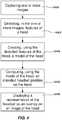
- a method of guiding positioning of electrodes for transcranial brain stimulation on a head of a user of the electrodescomprising: capturing, using a camera, one or more head images depicting the head; detecting, in the one or more head images, features of the head; creating, using the detected features of the head, a model of the head; computing, using the model of the head, intended positions of the electrodes on the head; and displaying, on a display, a representation of the electrodes as an overlay on an image of the head of the user.
- a user of the electrodes for transcranial brain stimulationmay film or photograph her head.
- a model of the headmay be created.
- the modelmay be a 2D or 3D model depending on what kind of images are available.
- a correct position of the electrodes relative the head of the usermay be overlaid on an image of the head of the user. This may guide the user to position the electrodes at correct positions relative the head of the user.
- a method for guiding the user of the electrodes to position the electrodes correctlyis provided. This may allow for a higher quality transcranial brain stimulation. Further, this may allow for a user to correctly fit the electrodes, e.g.
- the electrodesmay form part of a headset for transcranial brain stimulation.
- the headsetmay be any kind of support structure supporting the electrodes.
- the headsetmay comprise a rigid frame.
- the headsetmay be made of fabric, e.g. in the form of a headband or a cap.
- An example of correct positioning of the electrodesis a positioning according to the 10-20 system or international 10-20 system.
- Alternative positioning of the electrodesis a positioning according to the 10-10 system or according to the Omni-Lateral-Electrode, OLE, system.
- OLEOmni-Lateral-Electrode
- the methodmay further comprise: capturing one or more electrode images depicting the head of the user of the electrodes wearing the electrodes; detecting, in the one or more electrode images, features of the electrodes; computing, using the model of the head and the features of the electrodes, a relative position of the head and the electrodes; in response to the relative position of the head and the electrodes being above a threshold, computing, using the model of the head and the features of the electrodes, a direction of adjustment of the electrodes relative the head; communicating, to the user, information pertaining to the direction of adjustment of the electrodes relative the head.
- a model of the headmay be created.
- the modelmay be a 2D or 3D model depending on what kind of images are available.
- a current positioning of the electrodes relative the head of the usermay be found.
- a correct position of the electrodes relative the head of the usermay be overlaid on an image of the head of the user and verification if the electrodes is correctly positioned may be found. This may guide the user to position the electrodes, and especially the electrodes thereof, at the correct position relative the head of the user.
- a method for guiding the user of the electrodes to position the electrodes correctlyis provided.
- the positioning of the electrodesmay further be verified to be a correct position. This may allow for a higher quality transcranial brain stimulation. Further, this may allow for a user to correctly fit the electrodes, e.g. at home, without the need of a physician to be present. It may further allow for hindering a start of a treatment session in case of the position of the electrodes is not verified as being correct.
- a representation of the electrodes as an overlay on an image of the head of the user, augmented realitymay be used for verifying that the positioning of the electrodes, especially the electrodes of, is made correctly.
- the methodmay further comprise: in response to the relative position of the head and the electrodes being at or below the threshold, communicating, to the user, information pertaining to that the electrodes is correctly positioned.
- the methodmay further comprise: comparing the created model of the head to a plurality of predetermined models of heads, wherein each predetermined model of a head comprises information pertaining to positioning of the electrodes for that particular predetermined model of the head; and finding one predetermined model of a head being a best fit between the created model of the head and the plurality of predetermined models of heads, wherein the act of compute the relative position of the head and the electrodes is further based on the one found predetermined model of a head.
- the one or more electrode imagesmay be a subset of the one or more head images.
- the one or more electrode imagesmay be the same images as the one or more head images.
- the act of compute the intended electrodes position on the headmay further be based on the one found predetermined model of a head.
- a non-transitory computer-readable recording mediumhaving recorded thereon a program comprising program code portions which when executed on an electronic device having processing capabilities is configured to perform the method according to the first aspect is provided.
- a kitcomprising a headset for transcranial brain stimulation and a non-transitory computer-readable recording medium having recorded thereon a program which is executable on an electronic device having processing capabilities.
- the headsetcomprises a circuit comprising a first electrode and a second electrode.
- the programcomprises program code portions which when executed on the electronic device is configured to: receive one or more head images depicting a head of a user of the headset; detect, in the one or more head images, features of the head; create, using the detected features of the head, a model of the head; compute, using the model of the head, an intended headset position on the head; and display, on a display, a representation of the headset as an overlay on an image of the head of the user.
- the programmay further comprise program code portions which when executed on the electronic device is configured to: receive one or more headset images depicting the head of the user of the headset wearing the headset; detect, in the one or more headset images, features of the headset; compute, using the model of the head and the features of the headset, a relative position of the head and the headset; in response to the relative position of the head and the headset being above a threshold, compute, using the model of the head and the features of the headset, a direction of adjustment of the headset relative the head; and communicate, to the user, information pertaining to the direction of adjustment of the headset relative the head.
- the programmay further comprise program code portions which when executed on the electronic device is configured to: in response to the relative position of the head and the headset being at or below the threshold, communicate, to the user, information pertaining to that the headset is correctly positioned.
- the communication, to the usermay be performed by displaying information on a display and/or announcing information via a loudspeaker.
- the programfurther comprise program code portions which when executed on the electronic device is configured to: compare the created model of the head to a plurality of predetermined models of heads wherein each predetermined model of a head comprises information pertaining to positioning of the headset for that particular predetermined model of the head, in order to find one predetermined model of a head being a best fit between the created model of the head and the plurality of predetermined models of heads; and wherein compute the intended headset position on the head is further based on the one found predetermined model of a head.
- the programmay further comprise program code portions which when executed on the electronic device is configured to: capture, using a camera of the electronic device, the one or more headset images and/or the one or more head images.
- Compute the relative position of the head and the headsetmay be based on the one found predetermined model of a head.
- the headsetmay further comprise: a wireless transceiver configured to wirelessly communicate with the electronic device; a power source configured to provide power to the circuit; and a controller being configured to control powering of the circuit according to the control signal.
- the programmay further comprise program code portions which when executed on the electronic device is configured to: store, in a computer memory, a schedule for performing transcranial brain stimulation, and generate a control signal for the headset such that transcranial brain stimulation is performed according to the schedule for performing the transcranial brain stimulation.
- a kit 300 for transcranial brain stimulationcomprises a headset 100 for transcranial brain stimulation and a non-transitory computer-readable storage medium 154 having stored thereon a computer program being executable on a device having processing capabilities.
- the non-transitory computer-readable storage medium 154is typically located in an electronic device 150.
- the non-transitory computer-readable storage medium 154will in this context also be referred to as a memory of the electronic device 150.
- the memory 154may be any type of non-transitory computer-readable storage medium which may persistently store digital information.
- the memory 154may, e.g., be a solid state drive, a flash memory or any other device which may persistently store digital information.
- the electronic device 150comprises a processor 152 and the non-transitory computer-readable storage medium 154.
- the electronic devicemay e.g. be a handheld electronic device, such as a laptop, a smartphone, a tablet, or a smartwatch.
- the processor 152is configured to execute a computer program stored on the non-transitory computer-readable storage medium 154.
- the non-transitory computer-readable storage medium 154having recorded thereon a computer program which is executable by the processor 152 of the electronic device 150.
- the electronic device 150may further comprise a wireless transceiver 156.
- the wireless transceiver 156is configured to establish a communication channel with the headset 100.
- the wireless transceiver 156may be configured to wirelessly communicate with the headset 100.
- the electronic device 150may further comprise a network communication unit 158.
- the network communication unit 158is configured to establish a communication channel with a server via a computer network.
- the network communication unit 158is preferably configured to communicate wirelessly with the server.
- Any suitable wireless protocolsuch as 3G, 4G, 5G, or Wi-Fi, may be used.
- the communication between the electronic device 150 and the server and the communication between the electronic device 150 and the headset 100is preferably independent of each other.
- the computer programmay be an application downloadable to the electronic device 150 via an application providing service.
- the computer programcomprises code portions which when executed on the electronic device 150 is configured to perform different acts.
- a code portion of the computer programmay be configured to store a schedule for performing a transcranial brain stimulation in a computer memory.
- the schedule for performing transcranial brain stimulationmay comprise information pertaining to how often and/or when the headset 100 is to be used for performing a session of the transcranial brain stimulation. This information may e.g. be indicative of a time window within a session of the transcranial brain stimulation is to be performed.
- the time windowmay e.g. be defined with a specific day or with some specific days. For example, this information may be indicative of that the session shall be performed between certain hours of a day, that the session shall be performed every second day, etc.
- the usermay also be prompted to schedule the next session. Within the limits of the overall schedule.
- the usermay be prompted to plan when he/she will do the next session. This may comprise information on time and/or day for the next session. This information may then be put into the schedule for performing a transcranial brain stimulation. Hence, the schedule may be updated. The user may then be reminded so that the next session is performed at the next scheduled session. In this way the user may influence the schedule.
- the schedule for performing transcranial brain stimulationmay further comprise information pertaining to how a specific session shall be composed. This information may e.g. be indicative of currents to be used for a specific stimulus within the specific session, intervals between stimuli of the specific session, duration of a stimulus of the specific session, duration of the specific session, etc.
- the schedule for performing transcranial brain stimulationmay moreover comprise information pertaining to displaying of video sequence to be watched in connection with receiving the transcranial brain stimulation, see below for more details. This information may e.g. be indicative of which video sequence to be displayed and how often.
- the schedule for performing transcranial brain stimulationmay furthermore comprise information pertaining to execution of cognitive games to be played in connection with receiving the transcranial brain stimulation. This information may e.g. be indicative of which games to be executed and how often.
- the schedule for performing transcranial brain stimulationmay further comprise information pertaining to prompting the user to input information pertaining to status of the user.
- This informationmay e.g. be indicative of how often information pertaining to status of the user shall be prompted for. This provide the possibility for remote review of the status of the user. For example, the health of the user may be monitored in a continent manner without the need for a physician at the site of the user.
- the computer memory onto which the schedule for performing the transcranial brain stimulation is storedmay be a memory of the electronic device 150, for example, the non-transitory computer-readable storage medium 154.
- the computer memorymay be a memory of the headset 100.
- the computer memorymay be a memory of a server.
- the schedule for performing the transcranial brain stimulationmay be stored at a plurality of the above mentioned computer memories.
- the schedule for performing the transcranial brain stimulationmay be stored distributed on a plurality of the above mentioned computer memories. Hence, different portions of the schedule may be stored on different memories, the storing of the schedule may be distributed over a plurality of memories.
- the information pertaining to how often and/or when the headset is to be used for performing a session of the transcranial brain stimulationmay be stored on the memory of the electronic device and the information pertaining to how a specific session shall be composed may be stored on the memory of the headset.
- the full schedule for performing the transcranial brain stimulationmay be stored on the server.
- a code portion of the computer programmay be configured to generate a control signal for the headset 100.
- the control signalcomprising information pertain to how to control the headset 100 such that transcranial brain stimulation is performed according to the schedule for performing the transcranial brain stimulation.
- the control signalmay be seen as a, from the schedule, generated control signal, wherein the control signal is generated at the electronic device 150. This, at the electronic device 150 generated, control signal may then be sent from the electronic device 150 to the headset 100.
- a controller 210 of the headsetmay then be configured to control a transcranial brain stimulation according to the received control signal.
- control signalmay be seen as an extraction of a portion of the schedule for performing the transcranial brain stimulation, wherein the portion comprises information pertain to how to control the headset 100 such that transcranial brain stimulation is performed.
- the portion of the schedulemay then be sent from the electronic device 150 to the headset 100.
- the controller 210 of the headsetmay then be configured to control a transcranial brain stimulation according to the received portion of the schedule.
- a code portion of the computer programmay be configured to prompt a user of the electronic device to identify herself. By this it may be safeguarded that the headset for transcranial brain stimulation may only be used by users intended to use it.
- a code portion of the computer programmay further be configured to remind the user to use the headset according to the schedule for performing the transcranial brain stimulation. Reminding the user when the user shall use the headset 100 counteracts negligence or unwitting non-compliance, e.g. due to misunderstanding or miscommunication, in relation to the therapy on account of the patient.
- the remindermay be prompted to the user using one or more of a loudspeaker 155 of the electronic device 150, a light source of the electronic device 150, a vibrator of the electronic device 150 and a display 153 of the electronic device 150. For example, the user may be prompted by a message displayed on the display of the electronic device 150.
- the remindermay be prompted to the user using one or more of a loudspeaker 216, a light source 218 and a vibrator 220 of the headset 100.
- the loudspeaker 216, the light source 218 and the vibrator 220 of the headset 100will be discussed in more detail below.
- Thisprovides a kit for performing transcranial brain stimulation where the user can be conveniently prompted to wear the headset and signaled when to remove it. This provides a safety measure against over-use of the headset by the user due to negligence or ignorance. Further, by scheduling the use of the headset for transcranial brain stimulation the usage may be limited according to the schedule. In this way over-use may be avoided.
- the kitmay indicate this by issuing an error-message.
- the error messagemay be issued via a display 155 of the electronic device 150.
- the schedule for performing the transcranial brain stimulationmay comprise information pertaining to the frequency of usage of the headset for performing the transcranial brain stimulation. For example, one session per day, one session per every second day, X sessions per every week, etc.
- a code portion of the computer programmay further be configured to display information on the display 155 of the electronic device 150 in accordance with a schedule for displaying information.
- the schedule for displaying informationmay relate to the schedule for performing the transcranial brain stimulation.
- the displayed informationmay e.g. be a video sequence to be watched in connection with receiving the transcranial brain stimulation.
- the video sequencemay be video lesson being part of a treatment program.
- the video sequencemay be an instructions video instructing the user how to put on and use the headset 100.
- a code portion of the computer programmay further be configured to execute cognitive games.
- the user of the kit 300may for example be prompted to play a cognitive game during the transcranial brain stimulation.
- When to participate in the cognitive game and/or when to be exposed to a video lessonmay be part of the schedule for displaying information.
- Thisallow for setting up of a therapy program comprising both the actual transcranial brain stimulation but also to include viewing of videos and/or participation in cognitive games during or in between specific transcranial brain stimulation sessions.
- a kit providing enhanced treatment programsis provided.
- a code portion of the computer programmay further be configured to prompt the user to input information pertaining to status of the user.
- the usermay be prompted by displaying a message on the display of the electronic device 150.
- the input information prompted formay be information pertaining to information about the user's current health. For example, information according to Phq-9, Hamilton Rating Scale for Depression (HRSD), Beck Depression Inventory (BDI, BDI-1A, BDI-II), Montgomery ⁇ sberg Depression Rating Scale (MADRS, MADRS-s), Young Mania Rating Scale (YMRS) or any other psychiatric rating scale may be prompted for.
- HRSDHamilton Rating Scale for Depression
- BDIBeck Depression Inventory
- BDI-1ABDI-1A
- BDI-IIMontgomery ⁇ sberg Depression Rating Scale
- MADRSMontgomery ⁇ sberg Depression Rating Scale
- YMRSYoung Mania Rating Scale
- the input information prompted formay further be one or more of information pertaining to age of the user, sex of the user, intake of pharmaceuticals of the user, training habits of the user, eating habits of the user, sleeping habits of the user, the geographical location of the user, the user's relationship to their surrounding family/friends and working situation of the user.
- the usermay input such information through input means of the electronic device.
- An example of an input meansis a keyboard (virtual on a touch screen or realized as mechanical buttons).
- the input information pertaining to status of the usermay then be stored in the computer memory.
- the computer memory used for storing the input information pertaining to status of the usermay be the memory of the server.
- the input information pertaining to status of the usermay then be provided to a physician for reviewing the schedule for the transcranial brain stimulation of the user.
- a code portion of the computer programmay further be configured to store information pertaining to performed transcranial brain stimulation in a computer memory.
- the computer memorymay be the computer memory of the server.
- the information pertaining to performed transcranial brain stimulationmay then be provided to a physician for reviewing the schedule for the transcranial brain stimulation of the user of the kit 300. Hence, means for monitoring the patient's progress through the therapy is provided. This further reduces the need for involvement of a physician upon performing the transcranial brain stimulation.
- the physicianBy being provided with the input information pertaining to status of the user and the information pertaining to performed transcranial brain stimulation the physician is provided with the possibility to assess the progress of the user and to make any adjustments required to the user's schedule for transcranial brain stimulation as well as inform the user that such adjustments have been made.
- a code portion of the computer programmay further be configured to update the schedule for performing the transcranial brain stimulation. This gives the possibility, for e.g. the physician, to adjust the schedule for transcranial brain stimulation. This provide the possibility for remote update of the schedule for performing the transcranial brain stimulation. This further reduces the need for involvement of a physician at the site of the user upon performing the transcranial brain stimulation.
- Code portions of the computer programmay further be configured to guide a positioning of the headset 100 on a head of a user of the headset 100.
- correct positioning of the headset 100 comprising electrodeswill be discussed. It is however to be understood that it is the positioning of the electrodes that is of most importance. However, if the headset is correctly positioned also the electrodes are correctly positioned.
- An example of correct positioning of the electrodesis a positioning according to the 10-20 system or international 10-20 system.
- Alternative positioning of the electrodesis a positioning according to the 10-10 system or according to the Omni-Lateral-Electrode, OLE, system.
- the guiding of the positioning of the headset 100is based on that the user is capturing one or more images of her head. That is, the code portions are prompting the user to capture one or more images of the user's head.
- the one or more imagesare normally captured with the headset 100 being donned. Hence, the user may be prompted to film or photograph her head. Especially, the user may be prompted to film or photograph her head after the headset has been donned.
- a camera 151 of the electronic device 150may be used for capturing the one or more images. From the one or more images being filmed or photographed, at least some of them are received, by the code portions of the computer program being configured to guide the positioning of the headset 100, as one or more head images.
- the one or more head imagesare depicting the head of the user of the headset 100. In the one or more head images, features of the head are detected. Using the detected features of the head a model of the head may be created.
- the model of the headmay be made using various methods. Below two examples of such methods will be discussed. First an example based on a 2D scheme and thereafter an example based on a 3D scheme.
- a face within the one or more head imagesmay be detected using a face detection algorithm (e.g., using Haar cascades classifier or neural network).
- Features of the headmay thereafter be found using face key points detection (eyes, mouth, nose, face outline using Active shape model, neural network).
- face key pointsEyes, mouth, nose, face outline using Active shape model, neural network.
- a model of the headmay be created. For example, a parametric face model may be mapped to the detected key points.
- the 3D schemeoperates on a sequences of images. For example, the user may be prompted to sweep the camera in front of the head.
- the cameracan be single image camera or a stereo camera. Based on the sequences of images a Visual Inertial Odometry to track the motion of the camera in space (egomotion) may be performed.
- Features of the headmay be detected, using e.g., Haar cascades classifier or neural network.
- a model of the headmay be created based on the image sequence using the known egomotion of the camera and features of the head.
- an intended headset position on the headmay be computed. Thereafter a representation of the headset may be presented as an overlay on an image of the head of the user.
- a plurality of predetermined models of headsmay exist.
- Each predetermined model of a headmay comprise information pertaining to positioning of the headset for that particular predetermined model of the head.
- the predetermined models of headscontain information of how the headset 100, and especially the electrodes of the headset, shall be positioned for various head sizes/shapes.
- the intended headset position on the headmay be computed by finding a best fit between the plurality of predetermined models of heads and the created model of the head.
- a representation of the headset being correctly positionedmay then be overlaid on a camera image to guide the user to position the headset, and especially the electrodes thereof, at the correct position.
- a representation of the headset being correctly positionedmay then be overlaid as a virtually projection on top of the head of the user in an image of augmented reality glasses being worn by the user of the headset.
- the code portions configured to guide the positioning of the headset 100 on the head of the user of the headset 100may further be configured to detect the headset 100 position, especially the electrodes thereof, in the one or more captured images and verify the position of the headset 100 towards the model of the head. Hence, from the one or more images being filmed or photographed, at least some of them are received, by the code portions of the computer program being configured to guide the positioning of the headset 100, as one or more headset images.
- the one or more headset imagesare depicting the head of the user of the headset 100 wearing the headset 100.
- features of the headsetare detected.
- a model of the headset 100may be created. Hence, both the model of the head and the model of the headset may be mapped to the same image and their relative position in 2D or 3D may be compared.
- a relative position of the head and the headsetmay be computed.
- the position of the headset 100 donned on the head of the usermay be determined.
- the position of the electrodes 102A, 102B of the headset 100 being donned on the head on the usermay be determined.
- the correctness of the positioning of the headset 100, especially the electrodes 102A, 102B thereof, on the head of the usermay be determined.
- a verification of correct positioned headsetmay be made. In case the headset is not correctly positioned the user may be prompted to adjust the positioning of the headset 100, especially the electrodes thereof.
- a direction of adjustment of the headset relative the headmay be computed.
- the direction of adjustmentmay be computed using the model of the head and the features or model of the headset 100.
- the direction of adjustment of the headset relative the headmay be in relative or direct terms.
- the usermay be prompted to move the headset in a certain direction relative the head either by communicating in relative terms, e.g. move up the headset 100 upwards, downwards, to the left, to the right, etc., or by communicating in direct terms e.g. move up the headset 100 xcm upwards, ycm downwards, zcm to the left, kcm to the right, etc.
- information pertaining to the direction of adjustment of the headset relative the headmay then be communicated, to the user.
- the communication, to the usermay be performed by displaying information on a display.
- the displaymay be the display 153 of the electronic device 150 or a display of augmented reality glasses.
- the communication, to the usermay be performed by announcing information via a loudspeaker.
- the loudspeakermay be the loudspeaker 216 of the headset 100 and/or a loudspeaker 155 of the electronic device 150.
- information pertaining to that the headset 100 is correctly positionedmay be communicate to the user.
- This informationmay also be regarded as information pertaining to the direction of adjustment of the headset relative the head may then be communicated.
- the direction of adjacentcorresponds to no adjustment.
- the information pertaining to that the headset 100 is correctly positionedmay be communicate to the user by displaying information on a display and/or announcing information via a loudspeaker, just as discussed above for the adjustment information.
- the user of the headsetmay be visually and/or by audio guided towards a correct position of the headset 100. Further, a correct positioning of the headset 100 may be validated before a transcranial brain stimulation session is allowed to start. This kind of verification of correct positioning of the headset 100 on the head of the user may be used as a mandatory step before each transcranial brain stimulation session to make sure that the user has positioned the headset 100, especially the electrodes thereof, in the correct position.
- head images and or headset images and data about head sizes and placement of the headsetmay be collected and sent to a server 510, see Fig. 3 . This allows a physician to monitor a user's usage of the headset.
- Fig. 3illustrates a system 500 comprising a server 510 and a plurality of kits 300.
- the server 510is configured to individually communicate with the each of the plurality of kits 300.
- the communicationis realized by establishing communication channels 502 over a computer network or cellular network.
- the communication channels 502 between the server 510 and an electronic device 150 of a kit 300is independent from a communication channel 302 between the electronic device 150 of a kit 300 and a headset 100 of the kit 300.
- the server 510is configured to communicate with the electronic devices 150 in each of the plurality of kits 300.
- Such a system 500facilitates centralized planning of schedules for transcranial brain stimulation.
- Such a system 500also facilitates centralized evaluation of the performed treatment program comprising the transcranial brain stimulation and possibly also watching of video lessons, playing of cognitive games, etc.
- the system 500facilitates usage of the kit 300 for transcranial brain stimulation in a home environment with reduced need of in person consultation with a physician.
- the input information pertaining to status of the usermay be correlated with the information pertaining to performed transcranial brain stimulation.
- Such correlated informationmay be stored at the server 510. The correlation may be made by program code portions at the different electronic devices 150 or at the server 510. Further, such correlated information may be used for training e.g. an artificial neural network to determine a schedule for performing transcranial brain stimulation based on information pertaining to status of a user a kit 300 for transcranial brain stimulation.
- the transcranial brain stimulationto be as effective as possible the transcranial brain stimulation (and possibly also thereto associated cognitive games and/or video lessons, scheduling and motivational functions being part of a treatment program) is to be adapted to the individual user.
- a decision enginemay be used for performing this control.
- the decision enginemay comprise both hardcoded rules and learned rules.
- An example of such a decision engineis an engine based on reinforcement learning.
- the decision enginemay use individual traits and/or treatment history as input for determining a schedule for transcranial brain stimulation.
- the input/output mapping of the decision enginemay partly be based on hardcoded rules and partly on learned rules.
- the hardcoded rulesmay be derived from domain knowledge, for example in what order videos should be presented and how often the user shall be prompted to input information pertaining to status of the user.
- the learned rulesmay be derived using machine learning, for example based on reinforcement learning, supervised learning or unsupervised learning.
- the learning partmay, as mentioned above, be based on an artificial intelligence paradigm called reinforcement learning with the goal to detect nonobvious decision rules from large quantities of user data.
- Reinforcement learningdeals with problems where the outcome of a sequence of actions is delayed, which is what we have in our case.
- the actions of the decision engineare recommendations to the user, and the outcome we want to optimize for may be a subjective self-rating score of the user at the end of a treatment program comprising the transcranial brain stimulation.
- Reinforcement learningis a collection of methods to optimize these kind of decision sequences, by penalizing bad decisions and promoting good decisions based on an end outcome.
- the headsetcomprises first and second electrodes 102A, 102B.
- the first and second electrodes 102A, 102Bare comprised in a circuit 200.
- the circuit 200is configured to be powered according to a schedule for performing transcranial brain stimulation.
- the first and second electrodes 102A, 102Bare connected in the circuit 200.
- the circuit 200further comprises a power source 202 and a switch 203. Upon the headset 100 being worn by the user and upon the switch 203 is engaged, a closed circuit comprising the first and second electrodes 102A, 102B, the user's forehead and the power source 202 is formed. This allows current to flow through the user's cranium.
- the power source 202may be a battery.
- the batterymay be a chargeable battery.
- the headset 100may further comprise a controller 210.
- the controller 210is configured to periodically power the circuit 200 according to a schedule for performing transcranial brain stimulation. Thereby a current is periodically provided to user's brain for performing the transcranial brain stimulation.
- the controller 210is configured to periodically control the switch 203.
- the controller 210may be hardware or software implemented.
- the controller 210may comprise a microcontroller, a system of microcontrollers, or any type of processor or control circuit which can engage and disengage the switch 202. This provides a headset 100 which may vary the electric impulses to the head of the user according to schemes for transcranial brain stimulation.
- the headset 100may further comprise a memory 212.
- the memorymay be any type of non-volatile memory configured to store digital data.
- the memory 212may, e.g., be a solid state drive, a flash memory or any other device which can persistently store digital information.
- the memory 212may, e.g., be configured to store a schedule for performing the transcranial brain stimulation, or at least a portion of the schedule for performing the transcranial brain stimulation.
- the portion of the schedule for performing the transcranial brain stimulationcomprising information pertaining to how a specific session shall be composed, this information may e.g.
- the schedule for performing the transcranial brain stimulationmay comprise information pertaining to when to open and close the switch 203.
- the portion of the schedule for performing the transcranial brain stimulation stored on the memory 212 of the headset 100may comprise information pertaining to when the user shall wear the headset 100 in order to receive the transcranial brain stimulation.
- the controller 210may be arranged to read data from the memory 212.
- the controller 210may be configured to receive information from the memory 212 on the schedule for performing the transcranial brain stimulation.
- the schedule for transcranial brain stimulationmay be stored elsewhere in some other memory accessible by the controller 210.
- the controller 210may be arranged to receive data from other memories.
- the controller 210may be arranged to receive data from the electronic device 150.
- the controller 210may be arranged to receive data from the server 510.
- the controller 210may further be configured to write data to the memory 212.
- the controller 210may be configured to write data to the memory 212 pertaining to performed transcranial brain stimulation.
- means for monitoring the patient's progress through the therapyis provided. This further reduces the need for involvement of a physician upon performing the transcranial brain stimulation.
- the controller 210may be configured to write data to the memory 154 of the electronic device 150. This may be made by sending the information to be stored at the electronic device 150, via a wireless transceiver 214 of the headset 100, to the electronic device 150.
- the wireless transceiver 214is configured to wirelessly communicate with the electronic device 150. Any suitable wireless protocol, such as Bluetooth, Wi-Fi, ZigBee, or wireless USB, may be used. Hence, a wireless communication channel may be established between the wireless transceiver 214 of the headset 100 and the wireless transceiver 156 of the electronic device 150.
- the wireless communication channel between the wireless transceiver 214 of the headset 100 and the wireless transceiver 156 of the electronic device 150may further be used by the controller 210 of the headset 100 to receive data from the electronic device 150.
- data stored on the memory 154 of the electronic device 150e.g. data relating to the schedule for transcranial brain stimulation.
- the wireless communication channel between the wireless transceiver 214 of the headset 100 and the wireless transceiver 156 of the electronic device 150may be used by the controller 210 of the headset 100 to receive data routed by the electronic device 150.
- data stored on the memory of the server 510that are sent to the controller 210 via the electronic device 150.
- An example of data that may be routed by the electronic device 150is data relating to the schedule for transcranial brain stimulation that are stored on the memory of the server 510.
- the controller 210may be configured to write data to the memory of the server 510. Even that kind of data may be routed via the electronic device 150.
- the data written to the memory of the server 510may be data pertaining to performed transcranial brain stimulation.
- the headset 100may further be configured to signal when the user shall wear or take off the headset 100 for receiving the transcranial brain stimulation. Signaling to the user when the user shall wear or take off the headset 100 counteracts negligence or unwitting non-compliance, e.g. due to misunderstanding or miscommunication, in relation to the therapy on account of the patient.
- the signalingcan be done in many different ways.
- the headset 100may comprise a speaker 216.
- the controller 210may be configured to control the speaker 216.
- the speaker 216is configured to emit sound pertaining to information reminding the user to wear or remove the headset 100. Some nonlimiting examples of sounds are beeping sounds and voice synthesis.
- the loudspeaker 216may be arranged in the forehead frame 101.
- the headset 100may comprise a light source 218.
- the light source 218may e.g. comprise one or more LED:s.
- the controller 210may be configured to control the light source 218.
- the light source 218is configured to emit light pertaining to information reminding the user to wear or remove the headset 100.
- the light source 218may be configured to emit light having different colors for reminding the user to wear or remove the headset 100.
- the light source 218may be configured to emit light pulses of different frequency to remind the user.
- the light source 218may be arranged in the forehead frame 101.
- the headsetmay comprise a vibrator 220.
- the controller 210may be configured to control the vibrator 220.
- the vibrator 220is configured to emit vibrate in order to remind the user to wear or remove the headset 100.
- the vibratormay be arranged in the forehead frame 101. Any combination of the loudspeaker 216, the light source 218 or the vibrator 220 may be used for reminding the user to wear or remove the headset 100. Hence, just one of them, two of them, or all of them may be used for reminding the user to wear or remove the headset 100.
- the headset 100may be designed any various ways.
- a headset designis illustrated in Fig. 1 .
- the headset 100comprises a forehead frame 101 and a bracket 104.
- the shape of the forehead frame 101is designed to fit a forehead of a user of the headset 100.
- the forehead frameis designed as a single member. This member is shaped as an elongated arch.
- the forehead frame 101is defining an elongated arch. This allows the forehead frame 101 to follow approximately the shape of the forehead of the user when placed on the head.
- the forehead frame 101may be manufactured by e.g. plastic, composite materials, metal or any other suitable material.
- the forehead frame 101is configured to support the first and second electrodes 102A, 102B.
- the forehead frame 101is configured to support the bracket 104.
- the first electrode 102Ais arranged at a first end portion of the forehead frame 101.
- the second electrode 102Bis arranged at a second end portion of the forehead frame 101.
- the first and second electrodes 102A, 102Bare placed on the forehead frame 101 such that when the forehead frame 101 is worn by the user, the first and second electrodes 102A, 102B will come in contact with the forehead on either side of the user's head.
- the bracket 114is arranged at a center portion of the forehead frame 101.
- the bracket 104may be arranged to the forehead frame 101 in any suitable way.
- the bracket 104may be screwed, glued or fastened in any other suitable way to the fore head frame 101.
- the phrase "center portion"should be understood to refer to any part of the longitudinal extension of the forehead frame 101 which lies between the first and second electrodes 102A, 102B.
- the bracket 104has a longitudinal extension which, when the headset 100 is used, extends from the forehead of the user towards the back of the user's head.
- the bracket 104ensures that the user wears the headset 100 such that the first and second electrodes 102A, 102B come in contact only with their respective side of the user's forehead.
- the bracket 104may be constructed such that its extension from the frame is variable, ensuring a better fit for the user. This can be achieved in many ways, which the skilled person understands.
- the bracket 104may be of fixed length.
- the bracket 104may further comprise a support cushion 105 arranged at an end portion of the bracket 104 being opposite to where the bracket 104 is arranged at the forehead frame 101. The cushion 105 makes the bracket 104 more comfortable for the user.
- the in Fig. 1 illustrated exemplified headset 100provides a headset for performing transcranial brain stimulation wherein the electrodes are unlikely to be placed incorrectly on the forehead of the user.
- Thishas the advantage of allowing for transcranial brain stimulation to be performed without a physician available to place the electrodes on the head of the patient.
- the headsetmay be designed to be lightweight and comfortable, eliminating the need for fabric headwear which may be warm and uncomfortable when worn for extended periods of time.
- Thisfurther provides a comfortable headset which is impossible to mount such that the direction of the current is reversed, which may be critical in for example transcranial direct current stimulation, tDCS.
- the potential of neuronal cellsis influenced by an applied electric field. This field influences the neuronal cells under the stimulated area and pushes them closer or further away from their activation threshold.
- the first and second electrodes 102A, 102Bmay be configured to pivot to some degree.
- a headset 100is provided where the major surface of each electrode 102A, 102B is pivoted to be principally parallel to the surface of the forehead of the user.
- the first and second electrodes 102A, 102Bneed not be configured to pivot.
- a more comfortable headsetwhich is adaptable to many different shapes of patient foreheads and reduces the need for size adaptability of the headset is provided.
- the first and second electrodes 102A, 102Bmay be of any type of conducting material suitable for repeated use. Alternatively, the first and second electrodes 102A, 102B may be configured for one-time use only, in which case they are to be replaced by the user between uses.
- the first and second electrodes 102A, 102Bmay comprise an adhesive layer.
- the adhesive layermay be discarded after use.
- the adhesive layerensures proper contact between the electrode and the forehead of the user while also providing a hygienic solution.
- the adhesive layermay ensure that the headset 100 does not drift during use, securing it in place on the head of the patient.
- the headset 100may of course be provided with further electrodes, in case the desired scheme for transcranial brain stimulation so requires.
- the first and second electrodes 102A, 102Bcorrespond to a first and second side of the user's forehead, respectively.
- each electrode 102A, 102Bis configured to be brought into contact only with either the left or the right side of the user's forehead.
- the kitprovides the possibility for a user to perform a transcranial brain stimulation therapeutic schedule themselves with the aid of an electronic device, limiting the need for visits to or by a physician.
- the headsetdoes not need to be wired to any controller, improving portability of the headset and increasing user comfort and convenience.
- the in Fig. 1 illustrated example of a headset 100is just one example of a headset 100 that may be used in the kit 300 or system 500 for transcranial brain stimulation disclosed herein.
- the headset 100may be designed in many different alternative ways. According to one example, the headset 100 may not comprise the bracket 114 but only the forehead frame 101. According to another example, the headset 100 is a conventional fabric headwear.
- the methodcomprises one or more of the following acts.
- the actsmay be performed in any order suitable.
- Capturing S400one or more head images depicting the head of the user of the headset 100.
- the capturing S400may be made by a digital camera configured to capture still image.
- the capturing S400may be made by a digital camera configured to capture video images.
- the cameramay be a single image camera or a stereo camera.
- the one or more imagesis depicting the head of the user.
- the one or more head imagesmay be a plurality of head images. At least some of the plurality of head images may be headset images depicting the head of the user of the headset 100 wearing the headset 100. Hence, one or more headset images may be captured.
- Detecting S402in the one or more head images, features of the head.
- the features of the headmay be eyes, mouth, nose, and/or face outline.
- the featuresmay be detected using an active shape model or a neural network.
- Computing S406using the model of the head, an intended headset position on the head.
- the act of computing S406may comprise comparing the created model of the head to a plurality of predetermined models of heads, wherein each predetermined model of a head comprises information pertaining to positioning of the headset for that particular predetermined model of the head; and finding one predetermined model of a head being a best fit between the created model of the head and the plurality of predetermined models of heads.
- the image of the head of the usermay be an image of the one or more head images or an image of the one of more headset images.
- the displaymay be the display 153 of the electronic device 150 or a display of augmented reality glasses.
- a user of the headsetmay use the electronic device 150 to film or photograph her head.
- a model of the headmay be created.
- the modelmay be a 2D or 3D model depending on what kind of images are available from the electronic device 150.
- a correct position of the headset relative the head of the usermay be overlayed on an image of the head of the user. This will guide the user to position the headset, and especially the electrodes thereof, at a correct position relative the head of the user.
- the method of guiding positioning of the headset 100 for transcranial brain stimulation on a head of a user of the headset 100may further comprise one or more of the following acts.
- the actsmay be performed in any order suitable.
- the act of capturing S400may comprise capturing one or more headset images depicting the head of the user of the headset 100 wearing the headset 100.
- the features of the headsetmay e.g. comprise the electrodes 102A, 102B thereof.
- the act of computing a relative position of the head and the headset 100may comprise comparing the created model of the head to a plurality of predetermined models of heads, wherein each predetermined model of a head comprises information pertaining to positioning of the headset 100 for that particular predetermined model of the head, and finding one predetermined model of a head being a best fit between the created model of the head and the plurality of predetermined models of heads.
- a direction of adjustment of the headset relative the headIn response to the relative position of the head and the headset 100 being above a threshold, computing, using the model of the head and the features of the headset, a direction of adjustment of the headset relative the head.
- the direction of adjustment of the headset relative the headmay be in relative or direct terms.
- the usermay be prompted to move the headset in a certain direction relative the head either by communicating in relative terms, e.g. move up the headset 100 upwards, downwards, to the left, to the right, etc., or by communicating in direct terms e.g. move up the headset 100 xcm upwards, ycm downwards, zcm to the left, kcm to the right, etc.
- the act of communicating, to the usermay be performed by displaying information on a display and/or announcing information via a loudspeaker.
- the displaymay be the display 153 of the electronic device 150 or a display of augmented reality glasses.
- the loudspeakermay be the loudspeaker 216 of the headset 100 or a loudspeaker 155 of the electronic device 150.
- the act of communicatingmay further comprise, in response to the relative position of the head and the headset 100 being at or below the threshold, communicating, to the user, information pertaining to that the headset is correctly positioned.
- a model of the headmay be created.
- the modelmay be a 2D or 3D model depending on what kind of images are available from the electronic device 150.
- a current positioning of the headset relative the head of the usermay be found.
- a correct position of the headset relative the head of the usermay be overlayed on an image of the head of the user and verification if the headset is correctly positioned may be found. This will guide the user to position the headset, and especially the electrodes thereof, at the correct position relative the head of the user.
- the methodcomprises one or more of the following acts.
- the actsmay be performed in any order suitable.
- Capturing S500one or more headset images depicting the head of the user of the headset 100 wearing the headset 100.
- the capturing S500may be made by a digital camera configured to capture still image.
- the capturing S500may be made by a digital camera configured to capture video images.
- the cameramay be a single image camera or a stereo camera.
- the one or more headset imagesmay be a plurality of headset images.
- Detecting S502in the one or more headset images, features of the head.
- the features of the headmay be eyes, mouth, nose, and/or face outline.
- the featuresmay be detected using an active shape model or a neural network.
- the features of the headsetmay e.g. comprise the electrodes 102A, 102B thereof.
- Computing S508using the model of the head and the features of the headset 100, a relative position of the head and the headset 100.
- the act of computing S508may comprise comparing the created model of the head to a plurality of predetermined models of heads, wherein each predetermined model of a head comprises information pertaining to positioning of the headset 100 for that particular predetermined model of the head, and finding one predetermined model of a head being a best fit between the created model of the head and the plurality of predetermined models of heads.
- a direction of adjustment of the headset 100 relative the headIn response to the relative position of the head and the headset 100 being above a threshold, computing, using the model of the head and the features of the headset, a direction of adjustment of the headset 100 relative the head.
- the direction of adjustment of the headset 100 relative the headmay be in relative or direct terms.
- the usermay be prompted to move the headset in a certain direction relative the head either by communicating in relative terms, e.g. move up the headset 100 upwards, downwards, to the left, to the right, etc., or by communicating in direct terms e.g. move up the headset 100 xcm upwards, ycm downwards, zcm to the left, kcm to the right, etc.
- the act of communicating S510, to the user,may be performed by displaying information on a display and/or announcing information via a loudspeaker.
- the displaymay be the display 153 of the electronic device 150 or a display of augmented reality glasses.
- the loudspeakermay be the loudspeaker 216 of the headset 100 or a loudspeaker 155 of the electronic device 150.
- the act of communicating S510may further comprise, in response to the relative position of the head and the headset 100 being at or below the threshold, communicating, to the user, information pertaining to that the headset is correctly positioned.
- a model of the headmay be created.
- the modelmay be a 2D or 3D model depending on what kind of images are available from the electronic device 150.
- a current positioning of the headset relative the head of the usermay be found.
- a correct position of the headset relative the head of the usermay be overlayed on an image of the head of the user and verification if the headset is correctly positioned may be found. This will guide the user to position the headset, and especially the electrodes thereof, at the correct position relative the head of the user.
- the headsetcomprises a wireless transceiver.
- Thisprovides the possibility for the headset to communicate wirelessly with the electronic device over a network protocol such as Bluetooth or Wi-Fi.
- a network protocolsuch as Bluetooth or Wi-Fi.
- the skilled personunderstands that any network protocol capable of transmitting digitally represented data is possible to use.
- the systemmay, through the electronic device, also provide the user with information about the transcranial brain stimulation progress such as logs of their use, changes to their schedule recommended by the physician, status of the headset regarding e.g. battery charge state or malfunctions, or any other information.
- the power source 202 of the headset 100may be a chargeable battery.
- the headsetmay then comprise a charging port.
- the charging portmay be located on an inside surface of the forehead frame 101.
- the inside surface of the forehead frame 101being the surface of the forehead frame that is facing the forehead of the user upon use of the headset 100. This design will ensure that the headset cannot be charged upon usage of the same. This will enhance the safety of usage of the headset 100.
- a physicianmay use AR-glasses together with the above mentioned method of guiding positioning of a headset 100 for transcranial brain stimulation on a head of a user of the headset 100 in order to better position the headset 100 on the head of the user of the headset 100.
- points corresponding to correct positioning of the electrodesmay be displayed as an overlay on the head of the user.
- a headset, a kit and a system for transcranial brain stimulationis provided which allows a user to autonomously and conveniently perform steps of such treatment which previously required visits to or by a physician.
Landscapes
- Health & Medical Sciences (AREA)
- Life Sciences & Earth Sciences (AREA)
- Veterinary Medicine (AREA)
- Public Health (AREA)
- General Health & Medical Sciences (AREA)
- Animal Behavior & Ethology (AREA)
- Radiology & Medical Imaging (AREA)
- Nuclear Medicine, Radiotherapy & Molecular Imaging (AREA)
- Biomedical Technology (AREA)
- Engineering & Computer Science (AREA)
- Heart & Thoracic Surgery (AREA)
- Biophysics (AREA)
- Social Psychology (AREA)
- Psychology (AREA)
- Psychiatry (AREA)
- Neurology (AREA)
- Hospice & Palliative Care (AREA)
- Developmental Disabilities (AREA)
- Child & Adolescent Psychology (AREA)
- Electrotherapy Devices (AREA)
- User Interface Of Digital Computer (AREA)
- Measurement And Recording Of Electrical Phenomena And Electrical Characteristics Of The Living Body (AREA)
Description
- The present invention relates to positioning of electrodes for transcranial brain stimulation. A method for guiding and possibly also verify positioning of electrodes for transcranial brain stimulation on a head of a user of the electrodes is presented.
- Transcranial brain stimulation is, e.g., used to help stroke recovery and patients with brain injuries and to treat depression. An example of transcranial brain stimulation is transcranial direct current stimulation, tDCS, which is a well-known technique for non-invasive neurostimulation of the brain. Transcranial brain stimulation uses external electrodes placed on the head of the patient, whereby the head of the patient together with the electrodes forms a closed circuit. A current, either direct or alternating, is applied to the circuit, which acts on the neurons of the brain.
- However, there is a problem to ensure that the electrodes are positioned correctly. Positioning of the electrodes is typically made by a physician having experience in how to position a headset for transcranial brain stimulation such that the electrodes are positioned correctly. However, for some implementations of transcranial brain stimulation, e.g. to treat depression, it is highly impractical for a physician to be present at every treatment session. This since treatment is to be made on a daily basis for a period of time ranging from weeks to months. As mentioned in
WO2009137683 , the patient may be given the electrodes and instructions on how to place them, but this is of course error-prone. Further, according toWO 2016042499 A1 correct position a headset for transcranial brain stimulation may be secured by arranging a positioning indicator on the headset. The positioning indicator enables the user, during donning of the headset, to center the headset on the head of the user such that the at least one electrode is accurately positioned when the headset is donned. The positioning indicator is in the form of notches, or other tactilely distinguishable features, on the headset. The notches assist the user in donning the headset correctly by providing verification for headset placement, for example by helping the user confirm that the notches are aligned with the user's nose. The notches or other tactilely distinguishable features on the headset enables the user to verify the positioning of positioning indicator by feeling the positioning indicator simultaneously with feeling a centered part of her face, such as the nose bridge, without requiring visual assistance of a mirror or another person. However, positioning of the headset using the above positioning indicators may still be error-prone. GB 2 521 877 A - Accordingly, there is a need for alternative solutions on positioning of a headset for transcranial brain stimulation.
- In view of the above, an objective of the invention is to solve or at least reduce one or several of the drawbacks discussed above. Generally, the above objective is achieved by the attached independent patent claims.
- According to a first aspect a method of guiding positioning of electrodes for transcranial brain stimulation on a head of a user of the electrodes is provided. The method comprising: capturing, using a camera, one or more head images depicting the head; detecting, in the one or more head images, features of the head; creating, using the detected features of the head, a model of the head; computing, using the model of the head, intended positions of the electrodes on the head; and displaying, on a display, a representation of the electrodes as an overlay on an image of the head of the user.
- A user of the electrodes for transcranial brain stimulation may film or photograph her head. By detecting features of the head of the user a model of the head may be created. The model may be a 2D or 3D model depending on what kind of images are available. After having created the model of the head of the user a correct position of the electrodes relative the head of the user may be overlaid on an image of the head of the user. This may guide the user to position the electrodes at correct positions relative the head of the user. Hence, a method for guiding the user of the electrodes to position the electrodes correctly is provided. This may allow for a higher quality transcranial brain stimulation. Further, this may allow for a user to correctly fit the electrodes, e.g. at home, without the need of a physician to be present. The electrodes may form part of a headset for transcranial brain stimulation. The headset may be any kind of support structure supporting the electrodes. According to one example, the headset may comprise a rigid frame. According to another example, the headset may be made of fabric, e.g. in the form of a headband or a cap. Hence, a method for guiding the user of a headset for transcranial brain stimulation to position the headset correctly is provided. An example of correct positioning of the electrodes is a positioning according to the 10-20 system or international 10-20 system. Alternative positioning of the electrodes is a positioning according to the 10-10 system or according to the Omni-Lateral-Electrode, OLE, system. By displaying, a representation of the electrodes as an overlay on an image of the head of the user, augmented reality may be used for positioning of the headset, especially the electrodes of.
- The method may further comprise: capturing one or more electrode images depicting the head of the user of the electrodes wearing the electrodes; detecting, in the one or more electrode images, features of the electrodes; computing, using the model of the head and the features of the electrodes, a relative position of the head and the electrodes; in response to the relative position of the head and the electrodes being above a threshold, computing, using the model of the head and the features of the electrodes, a direction of adjustment of the electrodes relative the head; communicating, to the user, information pertaining to the direction of adjustment of the electrodes relative the head.
- After a user has positioned the electrodes on the head she may film or photograph her head. By detecting features of the head of the user a model of the head may be created. The model may be a 2D or 3D model depending on what kind of images are available. By detecting features of the electrodes a current positioning of the electrodes relative the head of the user may be found. After having created the model of the head of the user and finding the current positioning of the electrodes relative the head of the user, a correct position of the electrodes relative the head of the user may be overlaid on an image of the head of the user and verification if the electrodes is correctly positioned may be found. This may guide the user to position the electrodes, and especially the electrodes thereof, at the correct position relative the head of the user. Hence, a method for guiding the user of the electrodes to position the electrodes correctly is provided. The positioning of the electrodes may further be verified to be a correct position. This may allow for a higher quality transcranial brain stimulation. Further, this may allow for a user to correctly fit the electrodes, e.g. at home, without the need of a physician to be present. It may further allow for hindering a start of a treatment session in case of the position of the electrodes is not verified as being correct. By displaying, a representation of the electrodes as an overlay on an image of the head of the user, augmented reality may be used for verifying that the positioning of the electrodes, especially the electrodes of, is made correctly.
- The method may further comprise: in response to the relative position of the head and the electrodes being at or below the threshold, communicating, to the user, information pertaining to that the electrodes is correctly positioned.
- The method may further comprise: comparing the created model of the head to a plurality of predetermined models of heads, wherein each predetermined model of a head comprises information pertaining to positioning of the electrodes for that particular predetermined model of the head; and finding one predetermined model of a head being a best fit between the created model of the head and the plurality of predetermined models of heads, wherein the act of compute the relative position of the head and the electrodes is further based on the one found predetermined model of a head.
- The one or more electrode images may be a subset of the one or more head images. The one or more electrode images may be the same images as the one or more head images.
- The act of compute the intended electrodes position on the head may further be based on the one found predetermined model of a head.
- According to a second aspect a non-transitory computer-readable recording medium having recorded thereon a program comprising program code portions which when executed on an electronic device having processing capabilities is configured to perform the method according to the first aspect is provided.
- The above mentioned features of the method when applicable, apply to this second aspect as well. In order to avoid undue repetition, reference is made to the above.
- According to a second aspect a kit is provided. The kit comprises a headset for transcranial brain stimulation and a non-transitory computer-readable recording medium having recorded thereon a program which is executable on an electronic device having processing capabilities. The headset comprises a circuit comprising a first electrode and a second electrode. The program comprises program code portions which when executed on the electronic device is configured to: receive one or more head images depicting a head of a user of the headset; detect, in the one or more head images, features of the head; create, using the detected features of the head, a model of the head; compute, using the model of the head, an intended headset position on the head; and display, on a display, a representation of the headset as an overlay on an image of the head of the user.
- The program may further comprise program code portions which when executed on the electronic device is configured to: receive one or more headset images depicting the head of the user of the headset wearing the headset; detect, in the one or more headset images, features of the headset; compute, using the model of the head and the features of the headset, a relative position of the head and the headset; in response to the relative position of the head and the headset being above a threshold, compute, using the model of the head and the features of the headset, a direction of adjustment of the headset relative the head; and communicate, to the user, information pertaining to the direction of adjustment of the headset relative the head.
- The program may further comprise program code portions which when executed on the electronic device is configured to: in response to the relative position of the head and the headset being at or below the threshold, communicate, to the user, information pertaining to that the headset is correctly positioned. The communication, to the user, may be performed by displaying information on a display and/or announcing information via a loudspeaker.
- The program further comprise program code portions which when executed on the electronic device is configured to: compare the created model of the head to a plurality of predetermined models of heads wherein each predetermined model of a head comprises information pertaining to positioning of the headset for that particular predetermined model of the head, in order to find one predetermined model of a head being a best fit between the created model of the head and the plurality of predetermined models of heads; and wherein compute the intended headset position on the head is further based on the one found predetermined model of a head.
- The program may further comprise program code portions which when executed on the electronic device is configured to: capture, using a camera of the electronic device, the one or more headset images and/or the one or more head images.
- Compute the relative position of the head and the headset may be based on the one found predetermined model of a head.
- The headset may further comprise: a wireless transceiver configured to wirelessly communicate with the electronic device; a power source configured to provide power to the circuit; and a controller being configured to control powering of the circuit according to the control signal.
- The program may further comprise program code portions which when executed on the electronic device is configured to: store, in a computer memory, a schedule for performing transcranial brain stimulation, and generate a control signal for the headset such that transcranial brain stimulation is performed according to the schedule for performing the transcranial brain stimulation.
- The above mentioned features of the method when applicable, apply to this third aspect as well. In order to avoid undue repetition, reference is made to the above.
- A further scope of applicability of the present invention will become apparent from the detailed description given below. However, it should be understood that the detailed description and specific examples, while indicating preferred embodiments of the invention, are given by way of illustration only, since various changes and modifications within the scope of the invention will become apparent to those skilled in the art from this detailed description.
- Hence, it is to be understood that this invention is not limited to the particular component parts of the device described or steps of the methods described as such device and method may vary. It is also to be understood that the terminology used herein is for purpose of describing particular embodiments only, and is not intended to be limiting. It must be noted that, as used in the specification and the appended claim, the articles "a," "an," "the," and "said" are intended to mean that there are one or more of the elements unless the context clearly dictates otherwise. Thus, for example, reference to "a unit" or "the unit" may include several devices, and the like. Furthermore, the words "comprising", "including", "containing" and similar wordings does not exclude other elements or steps.
- The above and other aspects of the present invention will now be described in more detail, with reference to appended drawings showing embodiments of the invention. The figures should not be considered limiting the invention to the specific embodiment; instead they are used for explaining and understanding the invention.
- As illustrated in the figures, the sizes of layers and regions are exaggerated for illustrative purposes and, thus, are provided to illustrate the general structures of embodiments of the present invention. Like reference numerals refer to like elements throughout.
Fig. 1 illustrates a kit comprising a headset for transcranial brain stimulation and an electronic device configured to control the headset.Fig. 2 is a schematic sketch of a headset for transcranial brain stimulation.Fig. 3 illustrates a system for transcranial brain stimulation comprising a plurality of kits and a server.Fig. 4 is a block diagram of a method of guiding positioning of the headset for transcranial brain stimulation on a head of a user of the headset.Fig. 5 is a block diagram of an alternative method of guiding positioning of the headset for transcranial brain stimulation on a head of a user of the headset.- The present invention will now be described more fully hereinafter with reference to the accompanying drawings, in which currently preferred embodiments of the invention are shown. This invention may, however, be embodied in many different forms and should not be construed as limited to the embodiments set forth herein; rather, these embodiments are provided for thoroughness and completeness, and fully convey the scope of the invention to the skilled person.
- In
Fig. 1 , akit 300 for transcranial brain stimulation is illustrated. The kit comprises aheadset 100 for transcranial brain stimulation and a non-transitory computer-readable storage medium 154 having stored thereon a computer program being executable on a device having processing capabilities. The non-transitory computer-readable storage medium 154 is typically located in anelectronic device 150. The non-transitory computer-readable storage medium 154 will in this context also be referred to as a memory of theelectronic device 150. Thememory 154 may be any type of non-transitory computer-readable storage medium which may persistently store digital information. Thememory 154 may, e.g., be a solid state drive, a flash memory or any other device which may persistently store digital information. Theelectronic device 150 comprises aprocessor 152 and the non-transitory computer-readable storage medium 154. The electronic device may e.g. be a handheld electronic device, such as a laptop, a smartphone, a tablet, or a smartwatch. Theprocessor 152 is configured to execute a computer program stored on the non-transitory computer-readable storage medium 154. Hence, the non-transitory computer-readable storage medium 154 having recorded thereon a computer program which is executable by theprocessor 152 of theelectronic device 150. Theelectronic device 150 may further comprise awireless transceiver 156. Thewireless transceiver 156 is configured to establish a communication channel with theheadset 100. Thewireless transceiver 156 may be configured to wirelessly communicate with theheadset 100. Any suitable wireless protocol, such as Bluetooth, Wi-Fi, ZigBee, or wireless USB, may be used. Theelectronic device 150 may further comprise anetwork communication unit 158. Thenetwork communication unit 158 is configured to establish a communication channel with a server via a computer network. Thenetwork communication unit 158 is preferably configured to communicate wirelessly with the server. Any suitable wireless protocol, such as 3G, 4G, 5G, or Wi-Fi, may be used. The communication between theelectronic device 150 and the server and the communication between theelectronic device 150 and theheadset 100 is preferably independent of each other. - The computer program may be an application downloadable to the
electronic device 150 via an application providing service. The computer program comprises code portions which when executed on theelectronic device 150 is configured to perform different acts. - A code portion of the computer program may be configured to store a schedule for performing a transcranial brain stimulation in a computer memory. The schedule for performing transcranial brain stimulation may comprise information pertaining to how often and/or when the
headset 100 is to be used for performing a session of the transcranial brain stimulation. This information may e.g. be indicative of a time window within a session of the transcranial brain stimulation is to be performed. The time window may e.g. be defined with a specific day or with some specific days. For example, this information may be indicative of that the session shall be performed between certain hours of a day, that the session shall be performed every second day, etc. The user may also be prompted to schedule the next session. Within the limits of the overall schedule. For instance, the user may be prompted to plan when he/she will do the next session. This may comprise information on time and/or day for the next session. This information may then be put into the schedule for performing a transcranial brain stimulation. Hence, the schedule may be updated. The user may then be reminded so that the next session is performed at the next scheduled session. In this way the user may influence the schedule. - The schedule for performing transcranial brain stimulation may further comprise information pertaining to how a specific session shall be composed. This information may e.g. be indicative of currents to be used for a specific stimulus within the specific session, intervals between stimuli of the specific session, duration of a stimulus of the specific session, duration of the specific session, etc.
- The schedule for performing transcranial brain stimulation may moreover comprise information pertaining to displaying of video sequence to be watched in connection with receiving the transcranial brain stimulation, see below for more details. This information may e.g. be indicative of which video sequence to be displayed and how often.
- The schedule for performing transcranial brain stimulation may furthermore comprise information pertaining to execution of cognitive games to be played in connection with receiving the transcranial brain stimulation. This information may e.g. be indicative of which games to be executed and how often.
- The schedule for performing transcranial brain stimulation may further comprise information pertaining to prompting the user to input information pertaining to status of the user. This information may e.g. be indicative of how often information pertaining to status of the user shall be prompted for. This provide the possibility for remote review of the status of the user. For example, the health of the user may be monitored in a continent manner without the need for a physician at the site of the user.
- The computer memory onto which the schedule for performing the transcranial brain stimulation is stored may be a memory of the
electronic device 150, for example, the non-transitory computer-readable storage medium 154. Alternatively, the computer memory may be a memory of theheadset 100. Yet alternatively, the computer memory may be a memory of a server. Yet alternatively, the schedule for performing the transcranial brain stimulation may be stored at a plurality of the above mentioned computer memories. Further, alternatively, the schedule for performing the transcranial brain stimulation may be stored distributed on a plurality of the above mentioned computer memories. Hence, different portions of the schedule may be stored on different memories, the storing of the schedule may be distributed over a plurality of memories. For example, the information pertaining to how often and/or when the headset is to be used for performing a session of the transcranial brain stimulation may be stored on the memory of the electronic device and the information pertaining to how a specific session shall be composed may be stored on the memory of the headset. The full schedule for performing the transcranial brain stimulation may be stored on the server. - A code portion of the computer program may be configured to generate a control signal for the
headset 100. The control signal comprising information pertain to how to control theheadset 100 such that transcranial brain stimulation is performed according to the schedule for performing the transcranial brain stimulation. The control signal may be seen as a, from the schedule, generated control signal, wherein the control signal is generated at theelectronic device 150. This, at theelectronic device 150 generated, control signal may then be sent from theelectronic device 150 to theheadset 100. Acontroller 210 of the headset may then be configured to control a transcranial brain stimulation according to the received control signal. Alternatively, or in combination, the control signal may be seen as an extraction of a portion of the schedule for performing the transcranial brain stimulation, wherein the portion comprises information pertain to how to control theheadset 100 such that transcranial brain stimulation is performed. The portion of the schedule may then be sent from theelectronic device 150 to theheadset 100. Thecontroller 210 of the headset may then be configured to control a transcranial brain stimulation according to the received portion of the schedule. - A code portion of the computer program may be configured to prompt a user of the electronic device to identify herself. By this it may be safeguarded that the headset for transcranial brain stimulation may only be used by users intended to use it.
- A code portion of the computer program may further be configured to remind the user to use the headset according to the schedule for performing the transcranial brain stimulation. Reminding the user when the user shall use the
headset 100 counteracts negligence or unwitting non-compliance, e.g. due to misunderstanding or miscommunication, in relation to the therapy on account of the patient. The reminder may be prompted to the user using one or more of aloudspeaker 155 of theelectronic device 150, a light source of theelectronic device 150, a vibrator of theelectronic device 150 and adisplay 153 of theelectronic device 150. For example, the user may be prompted by a message displayed on the display of theelectronic device 150. Alternatively, or in combination, the reminder may be prompted to the user using one or more of aloudspeaker 216, alight source 218 and avibrator 220 of theheadset 100. Theloudspeaker 216, thelight source 218 and thevibrator 220 of theheadset 100 will be discussed in more detail below. This provides a kit for performing transcranial brain stimulation where the user can be conveniently prompted to wear the headset and signaled when to remove it. This provides a safety measure against over-use of the headset by the user due to negligence or ignorance. Further, by scheduling the use of the headset for transcranial brain stimulation the usage may be limited according to the schedule. In this way over-use may be avoided. If the user tries to over-use the headset the kit may indicate this by issuing an error-message. The error message may be issued via adisplay 155 of theelectronic device 150. The schedule for performing the transcranial brain stimulation may comprise information pertaining to the frequency of usage of the headset for performing the transcranial brain stimulation. For example, one session per day, one session per every second day, X sessions per every week, etc. - A code portion of the computer program may further be configured to display information on the
display 155 of theelectronic device 150 in accordance with a schedule for displaying information. The schedule for displaying information may relate to the schedule for performing the transcranial brain stimulation. The displayed information may e.g. be a video sequence to be watched in connection with receiving the transcranial brain stimulation. The video sequence may be video lesson being part of a treatment program. The video sequence may be an instructions video instructing the user how to put on and use theheadset 100. - A code portion of the computer program may further be configured to execute cognitive games. The user of the
kit 300 may for example be prompted to play a cognitive game during the transcranial brain stimulation. When to participate in the cognitive game and/or when to be exposed to a video lesson may be part of the schedule for displaying information. This allow for setting up of a therapy program comprising both the actual transcranial brain stimulation but also to include viewing of videos and/or participation in cognitive games during or in between specific transcranial brain stimulation sessions. Hence, a kit providing enhanced treatment programs is provided. - A code portion of the computer program may further be configured to prompt the user to input information pertaining to status of the user. The user may be prompted by displaying a message on the display of the
electronic device 150. The input information prompted for may be information pertaining to information about the user's current health. For example, information according to Phq-9, Hamilton Rating Scale for Depression (HRSD), Beck Depression Inventory (BDI, BDI-1A, BDI-II), Montgomery Åsberg Depression Rating Scale (MADRS, MADRS-s), Young Mania Rating Scale (YMRS) or any other psychiatric rating scale may be prompted for. The input information prompted for may further be one or more of information pertaining to age of the user, sex of the user, intake of pharmaceuticals of the user, training habits of the user, eating habits of the user, sleeping habits of the user, the geographical location of the user, the user's relationship to their surrounding family/friends and working situation of the user. - The user may input such information through input means of the electronic device. An example of an input means is a keyboard (virtual on a touch screen or realized as mechanical buttons). The input information pertaining to status of the user may then be stored in the computer memory. The computer memory used for storing the input information pertaining to status of the user may be the memory of the server. The input information pertaining to status of the user may then be provided to a physician for reviewing the schedule for the transcranial brain stimulation of the user.
- A code portion of the computer program may further be configured to store information pertaining to performed transcranial brain stimulation in a computer memory. The computer memory may be the computer memory of the server. The information pertaining to performed transcranial brain stimulation may then be provided to a physician for reviewing the schedule for the transcranial brain stimulation of the user of the
kit 300. Hence, means for monitoring the patient's progress through the therapy is provided. This further reduces the need for involvement of a physician upon performing the transcranial brain stimulation. - By being provided with the input information pertaining to status of the user and the information pertaining to performed transcranial brain stimulation the physician is provided with the possibility to assess the progress of the user and to make any adjustments required to the user's schedule for transcranial brain stimulation as well as inform the user that such adjustments have been made.
- A code portion of the computer program may further be configured to update the schedule for performing the transcranial brain stimulation. This gives the possibility, for e.g. the physician, to adjust the schedule for transcranial brain stimulation. This provide the possibility for remote update of the schedule for performing the transcranial brain stimulation. This further reduces the need for involvement of a physician at the site of the user upon performing the transcranial brain stimulation.
- Code portions of the computer program may further be configured to guide a positioning of the
headset 100 on a head of a user of theheadset 100. In the below description correct positioning of theheadset 100 comprising electrodes will be discussed. It is however to be understood that it is the positioning of the electrodes that is of most importance. However, if the headset is correctly positioned also the electrodes are correctly positioned. An example of correct positioning of the electrodes is a positioning according to the 10-20 system or international 10-20 system. Alternative positioning of the electrodes is a positioning according to the 10-10 system or according to the Omni-Lateral-Electrode, OLE, system. - The guiding of the positioning of the
headset 100 is based on that the user is capturing one or more images of her head. That is, the code portions are prompting the user to capture one or more images of the user's head. The one or more images are normally captured with theheadset 100 being donned. Hence, the user may be prompted to film or photograph her head. Especially, the user may be prompted to film or photograph her head after the headset has been donned. Acamera 151 of theelectronic device 150 may be used for capturing the one or more images. From the one or more images being filmed or photographed, at least some of them are received, by the code portions of the computer program being configured to guide the positioning of theheadset 100, as one or more head images. The one or more head images are depicting the head of the user of theheadset 100. In the one or more head images, features of the head are detected. Using the detected features of the head a model of the head may be created. - The model of the head may be made using various methods. Below two examples of such methods will be discussed. First an example based on a 2D scheme and thereafter an example based on a 3D scheme.
- Using the 2D scheme, a face within the one or more head images may be detected using a face detection algorithm (e.g., using Haar cascades classifier or neural network). Features of the head may thereafter be found using face key points detection (eyes, mouth, nose, face outline using Active shape model, neural network). Using the face key points, a model of the head may be created. For example, a parametric face model may be mapped to the detected key points.
- The 3D scheme operates on a sequences of images. For example, the user may be prompted to sweep the camera in front of the head. The camera can be single image camera or a stereo camera. Based on the sequences of images a Visual Inertial Odometry to track the motion of the camera in space (egomotion) may be performed. Features of the head may be detected, using e.g., Haar cascades classifier or neural network. A model of the head may be created based on the image sequence using the known egomotion of the camera and features of the head.
- Both for the 2D and 3D schemes, using the model of the head, an intended headset position on the head may be computed. Thereafter a representation of the headset may be presented as an overlay on an image of the head of the user.
- Both for the 2D and 3D schemes, a plurality of predetermined models of heads may exist. Each predetermined model of a head may comprise information pertaining to positioning of the headset for that particular predetermined model of the head. Hence, the predetermined models of heads contain information of how the
headset 100, and especially the electrodes of the headset, shall be positioned for various head sizes/shapes. The intended headset position on the head may be computed by finding a best fit between the plurality of predetermined models of heads and the created model of the head. - Hence, a representation of the headset being correctly positioned may then be overlaid on a camera image to guide the user to position the headset, and especially the electrodes thereof, at the correct position. Alternatively, or in combination, a representation of the headset being correctly positioned may then be overlaid as a virtually projection on top of the head of the user in an image of augmented reality glasses being worn by the user of the headset.
- The code portions configured to guide the positioning of the
headset 100 on the head of the user of theheadset 100 may further be configured to detect theheadset 100 position, especially the electrodes thereof, in the one or more captured images and verify the position of theheadset 100 towards the model of the head. Hence, from the one or more images being filmed or photographed, at least some of them are received, by the code portions of the computer program being configured to guide the positioning of theheadset 100, as one or more headset images. The one or more headset images are depicting the head of the user of theheadset 100 wearing theheadset 100. In the one or more headset images, features of the headset are detected. Using the detected features of the headset a model of theheadset 100 may be created. Hence, both the model of the head and the model of the headset may be mapped to the same image and their relative position in 2D or 3D may be compared. - Using the model of the head and the features of the headset 100 a relative position of the head and the headset may be computed. Hence, the position of the
headset 100 donned on the head of the user may be determined. Especially the position of theelectrodes headset 100 being donned on the head on the user may be determined. From this the correctness of the positioning of theheadset 100, especially theelectrodes headset 100, especially the electrodes thereof. For example, in response to the relative position of the head and the headset being above a threshold, a direction of adjustment of the headset relative the head may be computed. The direction of adjustment may be computed using the model of the head and the features or model of theheadset 100. The direction of adjustment of the headset relative the head may be in relative or direct terms. Hence, the user may be prompted to move the headset in a certain direction relative the head either by communicating in relative terms, e.g. move up theheadset 100 upwards, downwards, to the left, to the right, etc., or by communicating in direct terms e.g. move up theheadset 100 xcm upwards, ycm downwards, zcm to the left, kcm to the right, etc. - Accordingly, information pertaining to the direction of adjustment of the headset relative the head may then be communicated, to the user. The communication, to the user, may be performed by displaying information on a display. The display may be the
display 153 of theelectronic device 150 or a display of augmented reality glasses. Alternatively, or in combination, the communication, to the user, may be performed by announcing information via a loudspeaker. The loudspeaker may be theloudspeaker 216 of theheadset 100 and/or aloudspeaker 155 of theelectronic device 150. Further, in response to the relative position of the head and the headset being at or below the threshold, information pertaining to that theheadset 100 is correctly positioned may be communicate to the user. This information may also be regarded as information pertaining to the direction of adjustment of the headset relative the head may then be communicated. In this case, the direction of adjacent corresponds to no adjustment. Also the information pertaining to that theheadset 100 is correctly positioned may be communicate to the user by displaying information on a display and/or announcing information via a loudspeaker, just as discussed above for the adjustment information. - By this the user of the headset may be visually and/or by audio guided towards a correct position of the
headset 100. Further, a correct positioning of theheadset 100 may be validated before a transcranial brain stimulation session is allowed to start. This kind of verification of correct positioning of theheadset 100 on the head of the user may be used as a mandatory step before each transcranial brain stimulation session to make sure that the user has positioned theheadset 100, especially the electrodes thereof, in the correct position. - Further, head images and or headset images and data about head sizes and placement of the headset may be collected and sent to a
server 510, seeFig. 3 . This allows a physician to monitor a user's usage of the headset. Fig. 3 illustrates asystem 500 comprising aserver 510 and a plurality ofkits 300. Theserver 510 is configured to individually communicate with the each of the plurality ofkits 300. The communication is realized by establishingcommunication channels 502 over a computer network or cellular network. As mentioned above thecommunication channels 502 between theserver 510 and anelectronic device 150 of akit 300 is independent from acommunication channel 302 between theelectronic device 150 of akit 300 and aheadset 100 of thekit 300. Theserver 510 is configured to communicate with theelectronic devices 150 in each of the plurality ofkits 300. Such asystem 500 facilitates centralized planning of schedules for transcranial brain stimulation. Such asystem 500 also facilitates centralized evaluation of the performed treatment program comprising the transcranial brain stimulation and possibly also watching of video lessons, playing of cognitive games, etc. Hence, thesystem 500 facilitates usage of thekit 300 for transcranial brain stimulation in a home environment with reduced need of in person consultation with a physician.- Further, the input information pertaining to status of the user may be correlated with the information pertaining to performed transcranial brain stimulation. Such correlated information may be stored at the
server 510. The correlation may be made by program code portions at the differentelectronic devices 150 or at theserver 510. Further, such correlated information may be used for training e.g. an artificial neural network to determine a schedule for performing transcranial brain stimulation based on information pertaining to status of a user akit 300 for transcranial brain stimulation. For the transcranial brain stimulation to be as effective as possible the transcranial brain stimulation (and possibly also thereto associated cognitive games and/or video lessons, scheduling and motivational functions being part of a treatment program) is to be adapted to the individual user. Different users respond differently to the amount and order of brain stimulation, video lessons and/or cognitive games. Therefore, the transcranial brain stimulation, the video lessons and/or cognitive games is to be optimally controlled per user. A decision engine may be used for performing this control. The decision engine may comprise both hardcoded rules and learned rules. An example of such a decision engine is an engine based on reinforcement learning. The decision engine may use individual traits and/or treatment history as input for determining a schedule for transcranial brain stimulation. As mentioned above the input/output mapping of the decision engine may partly be based on hardcoded rules and partly on learned rules. The hardcoded rules may be derived from domain knowledge, for example in what order videos should be presented and how often the user shall be prompted to input information pertaining to status of the user. The learned rules may be derived using machine learning, for example based on reinforcement learning, supervised learning or unsupervised learning. The learning part may, as mentioned above, be based on an artificial intelligence paradigm called reinforcement learning with the goal to detect nonobvious decision rules from large quantities of user data. Reinforcement learning deals with problems where the outcome of a sequence of actions is delayed, which is what we have in our case. The actions of the decision engine are recommendations to the user, and the outcome we want to optimize for may be a subjective self-rating score of the user at the end of a treatment program comprising the transcranial brain stimulation. Important to note here is that we can't measure how good each recommendation is in itself, but instead only get to know the end outcome of a long sequence of recommendations. Reinforcement learning is a collection of methods to optimize these kind of decision sequences, by penalizing bad decisions and promoting good decisions based on an end outcome. - In connection with
Fig. 2 the headset will be discussed in more detail. The headset comprises first andsecond electrodes second electrodes circuit 200. Thecircuit 200 is configured to be powered according to a schedule for performing transcranial brain stimulation. The first andsecond electrodes circuit 200. Thecircuit 200 further comprises apower source 202 and aswitch 203. Upon theheadset 100 being worn by the user and upon theswitch 203 is engaged, a closed circuit comprising the first andsecond electrodes power source 202 is formed. This allows current to flow through the user's cranium. Thepower source 202 may be a battery. The battery may be a chargeable battery. - The
headset 100 may further comprise acontroller 210. Thecontroller 210 is configured to periodically power thecircuit 200 according to a schedule for performing transcranial brain stimulation. Thereby a current is periodically provided to user's brain for performing the transcranial brain stimulation. Thecontroller 210 is configured to periodically control theswitch 203. Thecontroller 210 may be hardware or software implemented. Thecontroller 210 may comprise a microcontroller, a system of microcontrollers, or any type of processor or control circuit which can engage and disengage theswitch 202. This provides aheadset 100 which may vary the electric impulses to the head of the user according to schemes for transcranial brain stimulation. - The
headset 100 may further comprise amemory 212. The memory may be any type of non-volatile memory configured to store digital data. Thememory 212 may, e.g., be a solid state drive, a flash memory or any other device which can persistently store digital information. Thememory 212 may, e.g., be configured to store a schedule for performing the transcranial brain stimulation, or at least a portion of the schedule for performing the transcranial brain stimulation. Especially, the portion of the schedule for performing the transcranial brain stimulation comprising information pertaining to how a specific session shall be composed, this information may e.g. be indicative of currents to be used for a specific stimulus within the specific session, intervals between stimuli of the specific session, duration of a stimulus of the specific session, duration of the specific session, etc. Hence, the schedule for performing the transcranial brain stimulation may comprise information pertaining to when to open and close theswitch 203. Further, the portion of the schedule for performing the transcranial brain stimulation stored on thememory 212 of theheadset 100 may comprise information pertaining to when the user shall wear theheadset 100 in order to receive the transcranial brain stimulation. Thecontroller 210 may be arranged to read data from thememory 212. Hence, thecontroller 210 may be configured to receive information from thememory 212 on the schedule for performing the transcranial brain stimulation. However, it is realized that the schedule for transcranial brain stimulation, or at least portions of the schedule for transcranial brain stimulation, may be stored elsewhere in some other memory accessible by thecontroller 210. For example, thecontroller 210 may be arranged to receive data from other memories. Thecontroller 210 may be arranged to receive data from theelectronic device 150. Thecontroller 210 may be arranged to receive data from theserver 510. Thecontroller 210 may further be configured to write data to thememory 212. Hence, thecontroller 210 may be configured to write data to thememory 212 pertaining to performed transcranial brain stimulation. Hence, means for monitoring the patient's progress through the therapy is provided. This further reduces the need for involvement of a physician upon performing the transcranial brain stimulation. Thecontroller 210 may be configured to write data to thememory 154 of theelectronic device 150. This may be made by sending the information to be stored at theelectronic device 150, via awireless transceiver 214 of theheadset 100, to theelectronic device 150. Thewireless transceiver 214 is configured to wirelessly communicate with theelectronic device 150. Any suitable wireless protocol, such as Bluetooth, Wi-Fi, ZigBee, or wireless USB, may be used. Hence, a wireless communication channel may be established between thewireless transceiver 214 of theheadset 100 and thewireless transceiver 156 of theelectronic device 150. - The wireless communication channel between the
wireless transceiver 214 of theheadset 100 and thewireless transceiver 156 of theelectronic device 150 may further be used by thecontroller 210 of theheadset 100 to receive data from theelectronic device 150. For example, data stored on thememory 154 of theelectronic device 150, e.g. data relating to the schedule for transcranial brain stimulation. Further, the wireless communication channel between thewireless transceiver 214 of theheadset 100 and thewireless transceiver 156 of theelectronic device 150 may be used by thecontroller 210 of theheadset 100 to receive data routed by theelectronic device 150. For example, data stored on the memory of theserver 510 that are sent to thecontroller 210 via theelectronic device 150. An example of data that may be routed by theelectronic device 150 is data relating to the schedule for transcranial brain stimulation that are stored on the memory of theserver 510. Moreover, thecontroller 210 may be configured to write data to the memory of theserver 510. Even that kind of data may be routed via theelectronic device 150. The data written to the memory of theserver 510 may be data pertaining to performed transcranial brain stimulation. - As was briefly mentioned above, the
headset 100 may further be configured to signal when the user shall wear or take off theheadset 100 for receiving the transcranial brain stimulation. Signaling to the user when the user shall wear or take off theheadset 100 counteracts negligence or unwitting non-compliance, e.g. due to misunderstanding or miscommunication, in relation to the therapy on account of the patient. The signaling can be done in many different ways. For this purpose, theheadset 100 may comprise aspeaker 216. Thecontroller 210 may be configured to control thespeaker 216. Thespeaker 216 is configured to emit sound pertaining to information reminding the user to wear or remove theheadset 100. Some nonlimiting examples of sounds are beeping sounds and voice synthesis. Theloudspeaker 216 may be arranged in theforehead frame 101. Theheadset 100 may comprise alight source 218. Thelight source 218 may e.g. comprise one or more LED:s. Thecontroller 210 may be configured to control thelight source 218. Thelight source 218 is configured to emit light pertaining to information reminding the user to wear or remove theheadset 100. For example, thelight source 218 may be configured to emit light having different colors for reminding the user to wear or remove theheadset 100. Thelight source 218 may be configured to emit light pulses of different frequency to remind the user. Thelight source 218 may be arranged in theforehead frame 101. The headset may comprise avibrator 220. Thecontroller 210 may be configured to control thevibrator 220. Thevibrator 220 is configured to emit vibrate in order to remind the user to wear or remove theheadset 100. The vibrator may be arranged in theforehead frame 101. Any combination of theloudspeaker 216, thelight source 218 or thevibrator 220 may be used for reminding the user to wear or remove theheadset 100. Hence, just one of them, two of them, or all of them may be used for reminding the user to wear or remove theheadset 100. - The
headset 100 may be designed any various ways. One example of a headset design is illustrated inFig. 1 . According to this exemplified design, theheadset 100 comprises aforehead frame 101 and a bracket 104. The shape of theforehead frame 101 is designed to fit a forehead of a user of theheadset 100. The forehead frame is designed as a single member. This member is shaped as an elongated arch. Hence, theforehead frame 101 is defining an elongated arch. This allows theforehead frame 101 to follow approximately the shape of the forehead of the user when placed on the head. Theforehead frame 101 may be manufactured by e.g. plastic, composite materials, metal or any other suitable material. - The
forehead frame 101 is configured to support the first andsecond electrodes forehead frame 101 is configured to support the bracket 104. Thefirst electrode 102A is arranged at a first end portion of theforehead frame 101. Thesecond electrode 102B is arranged at a second end portion of theforehead frame 101. Hence, the first andsecond electrodes forehead frame 101 such that when theforehead frame 101 is worn by the user, the first andsecond electrodes - The bracket 114 is arranged at a center portion of the
forehead frame 101. The bracket 104 may be arranged to theforehead frame 101 in any suitable way. For example, the bracket 104 may be screwed, glued or fastened in any other suitable way to thefore head frame 101. In this context the phrase "center portion" should be understood to refer to any part of the longitudinal extension of theforehead frame 101 which lies between the first andsecond electrodes headset 100 is used, extends from the forehead of the user towards the back of the user's head. In this way, the bracket 104 ensures that the user wears theheadset 100 such that the first andsecond electrodes support cushion 105 arranged at an end portion of the bracket 104 being opposite to where the bracket 104 is arranged at theforehead frame 101. Thecushion 105 makes the bracket 104 more comfortable for the user. - The in
Fig. 1 illustrated exemplifiedheadset 100 provides a headset for performing transcranial brain stimulation wherein the electrodes are unlikely to be placed incorrectly on the forehead of the user. This has the advantage of allowing for transcranial brain stimulation to be performed without a physician available to place the electrodes on the head of the patient. Furthermore, the headset may be designed to be lightweight and comfortable, eliminating the need for fabric headwear which may be warm and uncomfortable when worn for extended periods of time. This further provides a comfortable headset which is impossible to mount such that the direction of the current is reversed, which may be critical in for example transcranial direct current stimulation, tDCS. During electrical transcranial brain stimulation, the potential of neuronal cells is influenced by an applied electric field. This field influences the neuronal cells under the stimulated area and pushes them closer or further away from their activation threshold. - The first and
second electrodes headset 100 is provided where the major surface of eachelectrode second electrodes - The first and
second electrodes second electrodes - The first and
second electrodes headset 100 does not drift during use, securing it in place on the head of the patient. - The
headset 100 may of course be provided with further electrodes, in case the desired scheme for transcranial brain stimulation so requires. - For some schemes of transcranial brain stimulation, the first and
second electrodes electrode - The kit provides the possibility for a user to perform a transcranial brain stimulation therapeutic schedule themselves with the aid of an electronic device, limiting the need for visits to or by a physician. The headset does not need to be wired to any controller, improving portability of the headset and increasing user comfort and convenience.
- The in
Fig. 1 illustrated example of aheadset 100 is just one example of aheadset 100 that may be used in thekit 300 orsystem 500 for transcranial brain stimulation disclosed herein. Theheadset 100 may be designed in many different alternative ways. According to one example, theheadset 100 may not comprise the bracket 114 but only theforehead frame 101. According to another example, theheadset 100 is a conventional fabric headwear. - With reference to
Fig. 4 a method of guiding positioning of theheadset 100 for transcranial brain stimulation on a head of a user of theheadset 100 will be discussed. The method comprises one or more of the following acts. The acts may be performed in any order suitable. - Capturing S400 one or more head images depicting the head of the user of the
headset 100. The capturing S400 may be made by a digital camera configured to capture still image. The capturing S400 may be made by a digital camera configured to capture video images. The camera may be a single image camera or a stereo camera. The one or more images is depicting the head of the user. The one or more head images may be a plurality of head images. At least some of the plurality of head images may be headset images depicting the head of the user of theheadset 100 wearing theheadset 100. Hence, one or more headset images may be captured. - Detecting S402, in the one or more head images, features of the head. The features of the head may be eyes, mouth, nose, and/or face outline. The features may be detected using an active shape model or a neural network.
- Creating S404, using the detected features of the head, a model of the head.
- Computing S406, using the model of the head, an intended headset position on the head. The act of computing S406 may comprise comparing the created model of the head to a plurality of predetermined models of heads, wherein each predetermined model of a head comprises information pertaining to positioning of the headset for that particular predetermined model of the head; and finding one predetermined model of a head being a best fit between the created model of the head and the plurality of predetermined models of heads.
- Displaying S408, on a display, a representation of the headset as an overlay on an image of the head of the user. The image of the head of the user may be an image of the one or more head images or an image of the one of more headset images. The display may be the
display 153 of theelectronic device 150 or a display of augmented reality glasses. - A user of the headset may use the
electronic device 150 to film or photograph her head. By detecting features of the head of the user a model of the head may be created. The model may be a 2D or 3D model depending on what kind of images are available from theelectronic device 150. After having created the model of the head of the user a correct position of the headset relative the head of the user may be overlayed on an image of the head of the user. This will guide the user to position the headset, and especially the electrodes thereof, at a correct position relative the head of the user. - The method of guiding positioning of the
headset 100 for transcranial brain stimulation on a head of a user of theheadset 100 may further comprise one or more of the following acts. The acts may be performed in any order suitable. - The act of capturing S400 may comprise capturing one or more headset images depicting the head of the user of the
headset 100 wearing theheadset 100. - Detecting, in the one or more headset images, features of the
headset 100. The features of the headset may e.g. comprise theelectrodes - Computing, using the model of the head and the features of the
headset 100, a relative position of the head and theheadset 100. The act of computing a relative position of the head and theheadset 100 may comprise comparing the created model of the head to a plurality of predetermined models of heads, wherein each predetermined model of a head comprises information pertaining to positioning of theheadset 100 for that particular predetermined model of the head, and finding one predetermined model of a head being a best fit between the created model of the head and the plurality of predetermined models of heads. - In response to the relative position of the head and the
headset 100 being above a threshold, computing, using the model of the head and the features of the headset, a direction of adjustment of the headset relative the head. The direction of adjustment of the headset relative the head may be in relative or direct terms. Hence, the user may be prompted to move the headset in a certain direction relative the head either by communicating in relative terms, e.g. move up theheadset 100 upwards, downwards, to the left, to the right, etc., or by communicating in direct terms e.g. move up theheadset 100 xcm upwards, ycm downwards, zcm to the left, kcm to the right, etc. - Communicating, to the user, information pertaining to the direction of adjustment of the
headset 100 relative the head. The act of communicating, to the user, may be performed by displaying information on a display and/or announcing information via a loudspeaker. The display may be thedisplay 153 of theelectronic device 150 or a display of augmented reality glasses. The loudspeaker may be theloudspeaker 216 of theheadset 100 or aloudspeaker 155 of theelectronic device 150. - The act of communicating may further comprise, in response to the relative position of the head and the
headset 100 being at or below the threshold, communicating, to the user, information pertaining to that the headset is correctly positioned. - After a user has positioned the
headset 100 on the head she may use theelectronic device 150 to film or photograph her head. By detecting features of the head of the user a model of the head may be created. The model may be a 2D or 3D model depending on what kind of images are available from theelectronic device 150. By detecting features of the headset a current positioning of the headset relative the head of the user may be found. After having created the model of the head of the user and finding the current positioning of the headset relative the head of the user, a correct position of the headset relative the head of the user may be overlayed on an image of the head of the user and verification if the headset is correctly positioned may be found. This will guide the user to position the headset, and especially the electrodes thereof, at the correct position relative the head of the user. - With reference to
Fig. 5 a method of guiding positioning of theheadset 100 for transcranial brain stimulation on a head of a user of theheadset 100 will be discussed. The method comprises one or more of the following acts. The acts may be performed in any order suitable. - Capturing S500 one or more headset images depicting the head of the user of the
headset 100 wearing theheadset 100. The capturing S500 may be made by a digital camera configured to capture still image. The capturing S500 may be made by a digital camera configured to capture video images. The camera may be a single image camera or a stereo camera. The one or more headset images may be a plurality of headset images. - Detecting S502, in the one or more headset images, features of the head. The features of the head may be eyes, mouth, nose, and/or face outline. The features may be detected using an active shape model or a neural network.
- Creating S504, using the detected features of the head, a model of the head.
- Detecting S506, in the one or more headset images, features of the
headset 100. The features of the headset may e.g. comprise theelectrodes - Computing S508, using the model of the head and the features of the
headset 100, a relative position of the head and theheadset 100. The act of computing S508 may comprise comparing the created model of the head to a plurality of predetermined models of heads, wherein each predetermined model of a head comprises information pertaining to positioning of theheadset 100 for that particular predetermined model of the head, and finding one predetermined model of a head being a best fit between the created model of the head and the plurality of predetermined models of heads. - In response to the relative position of the head and the
headset 100 being above a threshold, computing, using the model of the head and the features of the headset, a direction of adjustment of theheadset 100 relative the head. The direction of adjustment of theheadset 100 relative the head may be in relative or direct terms. Hence, the user may be prompted to move the headset in a certain direction relative the head either by communicating in relative terms, e.g. move up theheadset 100 upwards, downwards, to the left, to the right, etc., or by communicating in direct terms e.g. move up theheadset 100 xcm upwards, ycm downwards, zcm to the left, kcm to the right, etc. - Communicating S510, to the user, information pertaining to the direction of adjustment of the
headset 100 relative the head. The act of communicating S510, to the user, may be performed by displaying information on a display and/or announcing information via a loudspeaker. The display may be thedisplay 153 of theelectronic device 150 or a display of augmented reality glasses. The loudspeaker may be theloudspeaker 216 of theheadset 100 or aloudspeaker 155 of theelectronic device 150. - The act of communicating S510 may further comprise, in response to the relative position of the head and the
headset 100 being at or below the threshold, communicating, to the user, information pertaining to that the headset is correctly positioned. - After a user has positioned the
headset 100 on the head she may use theelectronic device 150 to film or photograph her head. By detecting features of the head of the user a model of the head may be created. The model may be a 2D or 3D model depending on what kind of images are available from theelectronic device 150. By detecting features of the headset a current positioning of the headset relative the head of the user may be found. After having created the model of the head of the user and finding the current positioning of the headset relative the head of the user, a correct position of the headset relative the head of the user may be overlayed on an image of the head of the user and verification if the headset is correctly positioned may be found. This will guide the user to position the headset, and especially the electrodes thereof, at the correct position relative the head of the user. - The person skilled in the art realizes that the present invention by no means is limited to the preferred embodiments described above. On the contrary, many modifications and variations are possible within the scope of the appended claims.
- As described above, the headset comprises a wireless transceiver. This provides the possibility for the headset to communicate wirelessly with the electronic device over a network protocol such as Bluetooth or Wi-Fi. The skilled person understands that any network protocol capable of transmitting digitally represented data is possible to use.
- The system may, through the electronic device, also provide the user with information about the transcranial brain stimulation progress such as logs of their use, changes to their schedule recommended by the physician, status of the headset regarding e.g. battery charge state or malfunctions, or any other information.
- Further, the
power source 202 of theheadset 100 may be a chargeable battery. The headset may then comprise a charging port. The charging port may be located on an inside surface of theforehead frame 101. The inside surface of theforehead frame 101 being the surface of the forehead frame that is facing the forehead of the user upon use of theheadset 100. This design will ensure that the headset cannot be charged upon usage of the same. This will enhance the safety of usage of theheadset 100. - Further, A physician may use AR-glasses together with the above mentioned method of guiding positioning of a
headset 100 for transcranial brain stimulation on a head of a user of theheadset 100 in order to better position theheadset 100 on the head of the user of theheadset 100. For example, in the AR-glasses points corresponding to correct positioning of the electrodes may be displayed as an overlay on the head of the user. - As shown through this description, a headset, a kit and a system for transcranial brain stimulation is provided which allows a user to autonomously and conveniently perform steps of such treatment which previously required visits to or by a physician.
- Additionally, variations to the disclosed embodiments can be understood and effected by the skilled person in practicing the claimed invention, from a study of the drawings, the disclosure, and the appended claims.
Claims (13)
- A method of guiding positioning of electrodes for transcranial brain stimulation on a head of a user of the electrodes, the method comprising:capturing, using a camera, one or more head images depicting the head;detecting, in the one or more head images, features of the head;creating, using the detected features of the head, a model of the head;comparing the created model of the head to a plurality of predetermined models of heads, wherein each predetermined model of a head comprises information pertaining to positioning of the electrodes for that particular predetermined model of the head;finding one predetermined model of a head being a best fit between the created model of the head and the plurality of predetermined models of heads;computing, based on the one found predetermined model of a head, intended positions of the electrodes on the head; anddisplaying, on a display, a representation of the electrodes as an overlay on an image of the head of the user.
- The method according to claim 1, further comprising:capturing one or more electrode images depicting the head of the user of the electrodes wearing the electrodes;detecting, in the one or more electrode images, features of the electrodes;computing, using the model of the head and the features of the electrodes, a relative position of the head and the electrodes;in response to the relative position of the head and the electrodes being above a threshold, computing, using the model of the head and the features of the electrodes, a direction of adjustment of the electrodes relative the head;communicating, to the user, information pertaining to the direction of adjustment of the electrodes relative the head.
- The method according to claim 2, further comprising:
in response to the relative position of the head and the electrodes being at or below the threshold, communicating, to the user, information pertaining to that the electrodes are correctly positioned. - The method according to claim 2, wherein the act of compute the relative position of the head and the electrodes is further based on the one found predetermined model of a head.
- The method according to any one of claims 1-4, wherein the one or more electrode images is a subset of the one or more head images, or wherein the one or more electrode images is the same images as the one or more head images.
- A non-transitory computer-readable recording medium having recorded thereon a program comprising program code portions which when executed on an electronic device having processing capabilities is configured to perform the method according to any one of claims 1-5.
- A kit comprising:a headset (100) for transcranial brain stimulation, the headset (100) comprising a circuit (200) comprising a first electrode (102A), a second electrode (102B); anda non-transitory computer-readable recording medium having recorded thereon a program which is executable on an electronic device (150) having processing capabilities, wherein the program comprises program code portions which when executed on the electronic device (150) is configured to:receive one or more head images depicting a head of a user of the headset (100);detect, in the one or more head images, features of the head;create, using the detected features of the head, a model of the head;compare the created model of the head to a plurality of predetermined models of heads, wherein each predetermined model of a head comprises information pertaining to positioning of the headset for that particular predetermined model of the head;find one predetermined model of a head being a best fit between the created model of the head and the plurality of predetermined models of heads; andcompute, based on the one found predetermined model of a head, an intended headset position on the head; anddisplay, on a display, a representation of the headset as an overlay on an image of the head of the user.
- The kit according to claim 7, wherein the program further comprises program code portions which when executed on the electronic device (150) is configured to:receive one or more headset images depicting the head of the user of the headset (100) wearing the headset (100);detect, in the one or more headset images, features of the headset;compute, using the model of the head and the features of the headset, a relative position of the head and the headset;in response to the relative position of the head and the headset being above a threshold, compute, using the model of the head and the features of the headset, a direction of adjustment of the headset relative the head;communicate, to the user, information pertaining to the direction of adjustment of the headset relative the head.
- The kit according to claim 8, wherein the program further comprises program code portions which when executed on the electronic device (150) is configured to:
in response to the relative position of the head and the headset being at or below the threshold, communicate, to the user, information pertaining to that the headset is correctly positioned. - The kit according to claim 8 or 9, wherein the communication, to the user, is performed by displaying information on a display and/or announcing information via a loudspeaker.
- The kit according to claim any one of claims 8-10, wherein computing the relative position of the head and the headset, is further based on the one found predetermined model of a head.
- The kit according to any one of claims 7-11, wherein the program further comprises program code portions which when executed on the electronic device (150) is configured to:capture, using a camera (151) of the electronic device (150), the one or more headset images and/or the one or more head images.
- The kit according any one of claims 7-12,
wherein the headset (100) further comprises:a wireless transceiver (214) configured to wirelessly communicate with the electronic device (150);a power source (202) configured to provide power to the circuit (200); anda controller (210) being configured to control powering of the circuit (200) according to the control signal,and wherein the program further comprises program code portions which when executed on the electronic device is configured to:store, in a computer memory, a schedule for performing transcranial brain stimulation, andgenerate a control signal for the headset (100) such that transcranial brain stimulation is performed according to the schedule for performing the transcranial brain stimulation.
Priority Applications (6)
| Application Number | Priority Date | Filing Date | Title |
|---|---|---|---|
| EP18186520.5AEP3603737B1 (en) | 2018-07-31 | 2018-07-31 | Positioning of electrodes for transcranial brain stimulation |
| EP19742376.7AEP3829695B1 (en) | 2018-07-31 | 2019-07-23 | Positioning of electrodes for transcranial brain stimulation |
| CN201980047617.XACN112423835B (en) | 2018-07-31 | 2019-07-23 | Positioning of electrodes for transcranial brain stimulation |
| PCT/EP2019/069749WO2020025388A1 (en) | 2018-07-31 | 2019-07-23 | Positioning of electrodes for transcranial brain stimulation |
| US17/264,308US11779753B2 (en) | 2018-07-31 | 2019-07-23 | Positioning of electrodes for transcranial brain stimulation |
| US18/458,864US12246172B2 (en) | 2018-07-31 | 2023-08-30 | Positioning of electrodes for transcranial brain stimulation |
Applications Claiming Priority (1)
| Application Number | Priority Date | Filing Date | Title |
|---|---|---|---|
| EP18186520.5AEP3603737B1 (en) | 2018-07-31 | 2018-07-31 | Positioning of electrodes for transcranial brain stimulation |
Publications (2)
| Publication Number | Publication Date |
|---|---|
| EP3603737A1 EP3603737A1 (en) | 2020-02-05 |
| EP3603737B1true EP3603737B1 (en) | 2020-08-26 |
Family
ID=63108476
Family Applications (2)
| Application Number | Title | Priority Date | Filing Date |
|---|---|---|---|
| EP18186520.5AActiveEP3603737B1 (en) | 2018-07-31 | 2018-07-31 | Positioning of electrodes for transcranial brain stimulation |
| EP19742376.7AActiveEP3829695B1 (en) | 2018-07-31 | 2019-07-23 | Positioning of electrodes for transcranial brain stimulation |
Family Applications After (1)
| Application Number | Title | Priority Date | Filing Date |
|---|---|---|---|
| EP19742376.7AActiveEP3829695B1 (en) | 2018-07-31 | 2019-07-23 | Positioning of electrodes for transcranial brain stimulation |
Country Status (4)
| Country | Link |
|---|---|
| US (2) | US11779753B2 (en) |
| EP (2) | EP3603737B1 (en) |
| CN (1) | CN112423835B (en) |
| WO (1) | WO2020025388A1 (en) |
Families Citing this family (8)
| Publication number | Priority date | Publication date | Assignee | Title |
|---|---|---|---|---|
| US10315033B2 (en) | 2016-02-08 | 2019-06-11 | Halo Neuro, Inc. | Method and system for improving provision of electrical stimulation |
| EP3576835B1 (en) | 2017-02-02 | 2023-08-02 | Flow Neuroscience AB | Headset for transcranial direct-current stimulation, tdcs, and a system comprising the headset |
| EP3603737B1 (en) | 2018-07-31 | 2020-08-26 | Flow Neuroscience AB | Positioning of electrodes for transcranial brain stimulation |
| US12434049B2 (en)* | 2019-06-14 | 2025-10-07 | Regents Of The University Of Minnesota | System for unattended delivery of cognitive neuromodulation therapy |
| US11334995B2 (en)* | 2019-11-27 | 2022-05-17 | Shanghai United Imaging Intelligence Co., Ltd. | Hierarchical systems and methods for image segmentation |
| US11911569B2 (en) | 2020-07-31 | 2024-02-27 | Bioventures, Llc | Immersive distraction therapy |
| DE102021106334A1 (en) | 2021-03-16 | 2022-09-22 | Technische Universität Ilmenau, Körperschaft des öffentlichen Rechts, vertreten durch den Rektor | Method and system for generating and applying stimulation configurations on humans and associated computer program |
| AU2023366527A1 (en) | 2022-10-27 | 2025-05-15 | Flow Neuroscience, Inc. | Systems, devices, and methods of combining neuromodulation and pharmacologic treatment of depression |
Family Cites Families (164)
| Publication number | Priority date | Publication date | Assignee | Title |
|---|---|---|---|---|
| US3472233A (en) | 1966-12-02 | 1969-10-14 | Robert I Sarbacher | Electrical muscle stimulator |
| US4967038A (en) | 1986-12-16 | 1990-10-30 | Sam Techology Inc. | Dry electrode brain wave recording system |
| CS275292B2 (en) | 1989-02-22 | 1992-02-19 | Cvut Fakulta Elektrotechnick | Private rehabilitation apparatus with ion transcutaneous acceleration |
| US4977895A (en) | 1989-05-22 | 1990-12-18 | Ely Shavit Pasternak | Electrical apparatus for medical treatment |
| US5087242A (en) | 1989-07-21 | 1992-02-11 | Iomed, Inc. | Hydratable bioelectrode |
| US4928696A (en) | 1989-07-26 | 1990-05-29 | Mindcenter Corporation | Electrode-supporting headset |
| EP0429842B1 (en) | 1989-10-27 | 1996-08-28 | Korea Research Institute Of Chemical Technology | Device for the transdermal administration of protein or peptide drug |
| US5137817A (en) | 1990-10-05 | 1992-08-11 | Amoco Corporation | Apparatus and method for electroporation |
| US5387231A (en) | 1992-07-21 | 1995-02-07 | Sporer; Patsy | Electrotherapy method |
| US5622168A (en) | 1992-11-18 | 1997-04-22 | John L. Essmyer | Conductive hydrogels and physiological electrodes and electrode assemblies therefrom |
| US6480743B1 (en) | 2000-04-05 | 2002-11-12 | Neuropace, Inc. | System and method for adaptive brain stimulation |
| US20020169485A1 (en) | 1995-10-16 | 2002-11-14 | Neuropace, Inc. | Differential neurostimulation therapy driven by physiological context |
| US6230051B1 (en) | 1996-06-18 | 2001-05-08 | Alza Corporation | Device for enhancing transdermal agent delivery or sampling |
| JPH10234713A (en) | 1997-02-28 | 1998-09-08 | Rion Co Ltd | Bone conduction receiver for hearing examination |
| US6754361B1 (en) | 1997-04-17 | 2004-06-22 | 3M Innovative Properties Company | Ergonomic headset assembly |
| US6038464A (en) | 1998-02-09 | 2000-03-14 | Axelgaard Manufacturing Co., Ltd. | Medical electrode |
| US6077237A (en) | 1998-11-06 | 2000-06-20 | Adaboy, Inc. | Headset for vestibular stimulation in virtual environments |
| US6379324B1 (en) | 1999-06-09 | 2002-04-30 | The Procter & Gamble Company | Intracutaneous microneedle array apparatus |
| US6510333B1 (en) | 2000-05-16 | 2003-01-21 | Mark J. Licata | Sensor for biopotential measurements |
| US7024247B2 (en) | 2001-10-15 | 2006-04-04 | Northstar Neuroscience, Inc. | Systems and methods for reducing the likelihood of inducing collateral neural activity during neural stimulation threshold test procedures |
| US6505079B1 (en) | 2000-09-13 | 2003-01-07 | Foster Bio Technology Corp. | Electrical stimulation of tissue for therapeutic and diagnostic purposes |
| US7239919B2 (en) | 2001-04-27 | 2007-07-03 | Biophysical Mind Technologies, Ltd. | Diagnosis, treatment and research of mental disorder |
| US7643874B2 (en) | 2001-10-24 | 2010-01-05 | Power Paper Ltd. | Dermal patch |
| US7110820B2 (en) | 2002-02-05 | 2006-09-19 | Tcheng Thomas K | Responsive electrical stimulation for movement disorders |
| US7317948B1 (en) | 2002-02-12 | 2008-01-08 | Boston Scientific Scimed, Inc. | Neural stimulation system providing auto adjustment of stimulus output as a function of sensed impedance |
| FI20021050L (en) | 2002-05-31 | 2003-12-01 | Nexstim Oy | Targeting method and apparatus for magnetic brain stimulation |
| US20060229502A1 (en) | 2003-06-03 | 2006-10-12 | Bayer Healthcare Llc | Portable medical diagnostic apparatus |
| US20050165460A1 (en) | 2004-01-26 | 2005-07-28 | Onje' Erfan | Neuro-Electric-Therapy Headset |
| US8989840B2 (en) | 2004-03-30 | 2015-03-24 | Medtronic, Inc. | Lead electrode for use in an MRI-safe implantable medical device |
| EP1750799A2 (en) | 2004-05-04 | 2007-02-14 | The Cleveland Clinic Foundation | Methods of treating medical conditions by neuromodulation of the sympathetic nervous system |
| WO2006001276A1 (en) | 2004-06-25 | 2006-01-05 | Olympus Corporation | Brain wave detection electrode device and package |
| US7818515B1 (en) | 2004-08-10 | 2010-10-19 | Symantec Operating Corporation | System and method for enforcing device grouping rules for storage virtualization |
| DE102004048864A1 (en) | 2004-10-07 | 2006-04-13 | Roche Diagnostics Gmbh | Analytical test element with wireless data transmission |
| DE102005003735B4 (en) | 2005-01-26 | 2008-04-03 | Cerbomed Gmbh | Device for transcutaneous stimulation of a nerve of the human body |
| KR100634546B1 (en) | 2005-06-30 | 2006-10-13 | 삼성전자주식회사 | Bio signal measuring electrode |
| US7470958B2 (en) | 2005-07-28 | 2008-12-30 | Panasonic Corporation | Semiconductor device |
| US7499752B2 (en) | 2005-07-29 | 2009-03-03 | Cyberonics, Inc. | Selective nerve stimulation for the treatment of eating disorders |
| US7551952B2 (en) | 2005-10-26 | 2009-06-23 | Sam Technology, Inc. | EEG electrode headset |
| US8874227B2 (en) | 2009-03-20 | 2014-10-28 | ElectroCore, LLC | Devices and methods for non-invasive capacitive electrical stimulation and their use for vagus nerve stimulation on the neck of a patient |
| US7894905B2 (en) | 2006-03-13 | 2011-02-22 | Neuropace, Inc. | Implantable system enabling responsive therapy for pain |
| JP2009530064A (en) | 2006-03-22 | 2009-08-27 | エモーティブ システムズ ピーティーワイ リミテッド | Electrode and electrode headset |
| US20070237797A1 (en) | 2006-03-28 | 2007-10-11 | Gholam A. Peyman | Neural Conduit Agent Dissemination |
| US9352167B2 (en) | 2006-05-05 | 2016-05-31 | Rio Grande Neurosciences, Inc. | Enhanced spatial summation for deep-brain transcranial magnetic stimulation |
| US8116875B2 (en) | 2006-06-16 | 2012-02-14 | Neuropoint Medical, Inc. | Implantable neurostimulation systems |
| DE102006033623B4 (en) | 2006-07-18 | 2010-04-08 | Cerbomed Gmbh | System for transcutaneous stimulation of a nerve of the human body |
| US9079010B2 (en) | 2006-08-30 | 2015-07-14 | Nexstim Oy | Transcranial magnetic stimulation induction coil device with attachment portion for receiving tracking device |
| US7854232B2 (en) | 2006-08-30 | 2010-12-21 | Nexstim Oy | Transcranial magnetic stimulation induction coil device with attachment portion for receiving tracking device |
| CA2666529A1 (en) | 2006-10-13 | 2008-04-24 | Apnex Medical, Inc. | Obstructive sleep apnea treatment devices, systems and methods |
| EP2081644B1 (en) | 2006-10-31 | 2012-05-30 | St. Jude Medical AB | Tissue stimulating device |
| WO2008075250A1 (en) | 2006-12-18 | 2008-06-26 | Koninklijke Philips Electronics N.V. | Electrotherapeutic device |
| US20080177352A1 (en) | 2007-01-22 | 2008-07-24 | Novavision, Inc. | Device for Treating Human Vision Using Combined Optical and Electrical Stimulation |
| KR101002885B1 (en) | 2007-04-03 | 2010-12-21 | 연세대학교 산학협력단 | Apparatus and Method for Allocating Frequency Resource in Communication System |
| US8979837B2 (en) | 2007-04-04 | 2015-03-17 | St. Jude Medical, Atrial Fibrillation Division, Inc. | Flexible tip catheter with extended fluid lumen |
| US9694178B2 (en) | 2013-10-21 | 2017-07-04 | Neuroelectronics Barcelona S.L. | Method and a system for optimizing the configuration of multisite transcranial current stimulation and a computer-readable medium |
| CN101801445B (en) | 2007-08-14 | 2013-04-17 | 弗雷德哈钦森癌症研究中心 | Needle Array Assembly for Delivery of Therapeutic Drugs |
| US9757554B2 (en) | 2007-08-23 | 2017-09-12 | Bioness Inc. | System for transmitting electrical current to a bodily tissue |
| US8301265B2 (en) | 2007-09-10 | 2012-10-30 | Medtronic, Inc. | Selective depth electrode deployment for electrical stimulation |
| US8116841B2 (en) | 2007-09-14 | 2012-02-14 | Corventis, Inc. | Adherent device with multiple physiological sensors |
| WO2009042170A1 (en) | 2007-09-26 | 2009-04-02 | Medtronic, Inc. | Therapy program selection |
| WO2009051638A1 (en) | 2007-10-16 | 2009-04-23 | Medtronic, Inc. | Therapy control based on a patient movement state |
| US20090187159A1 (en) | 2008-01-17 | 2009-07-23 | California Institute Of Technology | Chronically implantable hybrid cannula-microelectrode system for continuous monitoring electrophysiological signals during infusion of a chemical or pharmaceutical agent |
| EP2092951A1 (en) | 2008-02-20 | 2009-08-26 | Stx-Med Sprl | Device for electrotherapeutical treatment of tension headaches |
| WO2009134763A1 (en) | 2008-04-29 | 2009-11-05 | Board of Governors for Higher Education, State of Rhode Island and the Providence Plantations | Biomedical sensors usable on un-prepared contact surfaces |
| WO2009137683A2 (en) | 2008-05-07 | 2009-11-12 | Hoffman Ross G | Transcranial direct current stimulation apparatus and methods |
| EP2288408B1 (en) | 2008-05-16 | 2013-07-17 | Koninklijke Philips Electronics N.V. | A method and system for dynamic recalibration of tens stimulation points to compensate for changing electrode conditions with fail-safe and auto-recovery functionality |
| BRPI0914310A2 (en) | 2008-06-20 | 2015-10-13 | Medrelife Inc | systems, apparatus, and methods for providing non-transcranial electrotherapy |
| CN101971013B (en) | 2008-08-26 | 2013-06-19 | 松下电器产业株式会社 | Artificial lipid membrane forming method and artificial lipid membrane forming apparatus |
| DE102008043973B4 (en) | 2008-11-21 | 2011-12-01 | Burkhard Brocke | Device for transcranial neurostimulation |
| US20150099921A1 (en) | 2008-11-26 | 2015-04-09 | M. Bret Schneider | Treatment of degenerative brain disorders using transcranial magnetic stimulation |
| AU2008365106B2 (en) | 2008-12-11 | 2015-02-05 | Bio-Medical Research Limited | Facial stimulation apparatus |
| JP5579984B2 (en) | 2008-12-25 | 2014-08-27 | 楽天株式会社 | Presentation information registration device |
| AU2009334503B2 (en) | 2008-12-30 | 2013-09-12 | Research Foundation Of The City University Of New York | Methods for reducing discomfort during electrostimulation, and compositions and apparatus therefor |
| US20100268287A1 (en) | 2009-03-13 | 2010-10-21 | The Johns Hopkins University | Methods and devices for increasing learning and effects of training in healthy individuals and patients after brain lesions using dc stimulation and apparatuses and systems related thereto |
| US20190111255A1 (en) | 2009-03-20 | 2019-04-18 | Electrocore, Inc. | Systems and methods for initial provisioning and refilling of medical devices |
| US8989863B2 (en) | 2009-03-23 | 2015-03-24 | Flint Hills Scientific, Llc | System and apparatus for increasing regularity and/or phase-locking of neuronal activity relating to an epileptic event |
| KR101035967B1 (en) | 2009-04-01 | 2011-05-23 | 주식회사 애트랩 | Contact sensor device |
| DK2414038T3 (en) | 2009-04-03 | 2016-01-18 | Neuronix Ltd | System for neurological treatment |
| WO2010134006A2 (en) | 2009-05-18 | 2010-11-25 | Koninklijke Philips Electronics N.V. | Arrangement and method for influencing and/or detecting magnetic particles |
| JP5589593B2 (en) | 2009-06-29 | 2014-09-17 | ソニー株式会社 | Biological signal measuring device |
| GB0917600D0 (en) | 2009-10-07 | 2009-11-25 | Univ Edinburgh | Testing apparatus and method |
| CA2779842C (en) | 2009-11-04 | 2021-06-22 | Arizona Board Of Regents For And On Behalf Of Arizona State University | Devices and methods for modulating brain activity |
| TR201903768T4 (en) | 2009-11-04 | 2019-04-22 | Koninklijke Philips Nv | A device for positioning electrodes on a user's scalp. |
| US9770204B2 (en) | 2009-11-11 | 2017-09-26 | Medtronic, Inc. | Deep brain stimulation for sleep and movement disorders |
| US8373238B2 (en) | 2009-12-03 | 2013-02-12 | Taiwan Semiconductor Manufacturing Company, Ltd. | FinFETs with multiple Fin heights |
| US8838247B2 (en) | 2010-01-06 | 2014-09-16 | Evoke Neuroscience, Inc. | Transcranial stimulation device and method based on electrophysiological testing |
| US8938301B2 (en) | 2010-01-06 | 2015-01-20 | Evoke Neuroscience, Inc. | Headgear with displaceable sensors for electrophysiology measurement and training |
| US8239030B1 (en) | 2010-01-06 | 2012-08-07 | DJ Technologies | Transcranial stimulation device and method based on electrophysiological testing |
| US20160017558A1 (en) | 2010-04-23 | 2016-01-21 | French Development Enterprises, LLC | Aquatic Animal Passage With Counter |
| US8583237B2 (en) | 2010-09-13 | 2013-11-12 | Cranial Medical Systems, Inc. | Devices and methods for tissue modulation and monitoring |
| US8473063B2 (en) | 2010-09-22 | 2013-06-25 | Medtronic, Inc. | Method and apparatus for event-triggered reinforcement of a favorable brain state |
| CN201814996U (en) | 2010-10-22 | 2011-05-04 | 四川大学 | Denervated swallowing electrical stimulation device |
| DE102010052710B4 (en) | 2010-11-26 | 2021-12-02 | Horst Dittmann E.K. | TENS or EMS device for transcutaneous electrical nerve stimulation or electrical muscle stimulation |
| WO2012092628A2 (en) | 2010-12-31 | 2012-07-05 | Incube Labs, Llc | Patches and methods for the transdermal delivery of agents to treat hair loss |
| US8706181B2 (en) | 2011-01-25 | 2014-04-22 | Medtronic, Inc. | Target therapy delivery site selection |
| CN103619406B (en) | 2011-06-03 | 2016-09-21 | 奈科斯迪姆公司 | Methods and systems for combining anatomical connectivity patterns and navigating brain stimulation |
| CN103619407B (en) | 2011-06-03 | 2016-05-11 | 奈科斯迪姆公司 | Method and system for overlaying NBS functional data on real-time images of the brain |
| DE102011078696A1 (en) | 2011-07-05 | 2013-01-10 | Smp Swiss Macro Polymers Ag | Assembly of fabric sleeve and curing material for securing an anchoring element in a borehole |
| US20130204315A1 (en) | 2011-08-05 | 2013-08-08 | Ndi Medical, Llc | Systems for and methods of transcranial direct current electrical stimulation |
| CA3061930C (en) | 2011-09-22 | 2023-09-12 | Djo, Llc | Devices and systems for treating pain with electrical stimulation |
| KR101826912B1 (en) | 2011-11-07 | 2018-02-08 | 인텔렉츄얼 키스톤 테크놀로지 엘엘씨 | Photovoltaic device and the manufacturing methode thereof |
| US9827420B2 (en) | 2013-03-29 | 2017-11-28 | Neurometrix, Inc. | Transcutaneous electrical nerve stimulator with user gesture detector and electrode-skin contact detector, with transient motion detector for increasing the accuracy of the same |
| PT2780073T (en) | 2011-11-15 | 2017-12-18 | Neurometrix Inc | Apparatus for relieving pain using transcutaneous electrical nerve stimulation |
| BE1020458A3 (en) | 2012-01-13 | 2013-10-01 | Stx Med Sprl | AUTONOMOUS ELECTRONIC APPARATUS AND DIPOSITIVE FIXING THE SAME ON A LOCALIZED ELECTRODE AT THE HEAD FOR USE IN THE LAYERED POSITION OF THE PATIENT. |
| US8818515B2 (en) | 2012-01-13 | 2014-08-26 | Research Foundation Of The City University Of New York | Voltage limited neurostimulation |
| WO2013113059A1 (en) | 2012-01-31 | 2013-08-08 | Creativity Cap | A method and device for increasing human ability for idea generation and insight related tasks using dc stimulation |
| CN107029349A (en) | 2012-03-09 | 2017-08-11 | 安特罗麦迪克斯公司 | Safety feature in Medical Devices |
| US20130261706A1 (en) | 2012-03-30 | 2013-10-03 | Neuropace, Inc. | Systems and methods for applying rapid sequential electrode stimulation |
| WO2013152035A1 (en) | 2012-04-02 | 2013-10-10 | Neurotrek, Inc. | Device and methods for targeting of transcranial ultrasound neuromodulation by automated transcranial doppler imaging |
| EP2863986A4 (en) | 2012-06-22 | 2016-01-20 | Thync Inc | Device and methods for noninvasive neuromodulation using targeted transcrannial electrical stimulation |
| WO2014043037A1 (en) | 2012-09-11 | 2014-03-20 | SynTouch, LLC | Compliant tactile sensor with fluid-filled, sponge-like material |
| US20160361534A9 (en) | 2012-11-16 | 2016-12-15 | Rio Grande Neurosciences, Inc. | Variably configurable, adaptable electrode arrays and effectuating software, methods, and systems |
| US10946196B2 (en) | 2012-11-16 | 2021-03-16 | Stimscience Inc. | System for variably configurable, adaptable electrode arrays and effectuating software |
| US10537703B2 (en) | 2012-11-26 | 2020-01-21 | Thync Global, Inc. | Systems and methods for transdermal electrical stimulation to improve sleep |
| US10814131B2 (en) | 2012-11-26 | 2020-10-27 | Thync Global, Inc. | Apparatuses and methods for neuromodulation |
| US8903494B2 (en) | 2012-11-26 | 2014-12-02 | Thync, Inc. | Wearable transdermal electrical stimulation devices and methods of using them |
| US9440070B2 (en) | 2012-11-26 | 2016-09-13 | Thyne Global, Inc. | Wearable transdermal electrical stimulation devices and methods of using them |
| US9446243B2 (en) | 2012-12-07 | 2016-09-20 | Boston Scientific Neuromodulation Corporation | Patient posture determination and stimulation program adjustment in an implantable stimulator device using impedance fingerprinting |
| EP2928552A1 (en) | 2012-12-07 | 2015-10-14 | Koninklijke Philips N.V. | Apparatus and method relating to an electrostimulation device |
| US8874220B2 (en) | 2012-12-13 | 2014-10-28 | Nuraleve Inc. | Neurostimulation system, device, and method |
| WO2014117208A1 (en) | 2013-01-29 | 2014-08-07 | National Ict Australia Limited | Neuroprosthetic stimulation |
| US8989836B2 (en) | 2013-03-08 | 2015-03-24 | Brainscope Company, Inc. | Electrode array and method of placement |
| US8880173B2 (en) | 2013-03-12 | 2014-11-04 | Ethicon Endo-Surgery, Inc. | Device for providing transdermal electrical stimulation at an adjustable position on a head |
| CN105188835B (en) | 2013-03-15 | 2018-04-13 | 纽洛利夫有限公司 | Headgear for treatment and assessment of disease |
| US9913973B2 (en) | 2013-04-23 | 2018-03-13 | Yani Skincare, LLC | Transcranial direct current brain stimulation apparatus |
| AU2014257024B2 (en) | 2013-04-24 | 2019-05-09 | Neurosigma, Inc. | Modulation of autonomic nervous system activity and integrated electrode assemblies for trigeminal neurostimulation |
| JP6410369B2 (en) | 2013-06-29 | 2018-10-24 | セレヴァスト メディカル インク.Cerevast Medical Inc. | Transcutaneous electrical stimulation device for correcting or inducing cognitive state |
| US9486618B2 (en) | 2013-08-27 | 2016-11-08 | Halo Neuro, Inc. | Electrode system for electrical stimulation |
| US9889290B2 (en) | 2013-08-27 | 2018-02-13 | Halo Neuro, Inc. | Electrode system for electrical stimulation |
| KR20160046887A (en) | 2013-08-27 | 2016-04-29 | 헤일로우 뉴로 아이엔씨. | Method and system for providing electrical stimulation to a user |
| US9782585B2 (en) | 2013-08-27 | 2017-10-10 | Halo Neuro, Inc. | Method and system for providing electrical stimulation to a user |
| US10076279B2 (en) | 2013-10-22 | 2018-09-18 | Neba Health, Llc | System and method for a compact EEG headset |
| US10188342B2 (en) | 2013-11-05 | 2019-01-29 | The University Of North Carolina At Chapel Hill | Methods, apparatuses and systems for transcranial stimulation |
| GB2521877B (en)* | 2014-01-07 | 2016-03-23 | Sooma Oy | System and method for transcranial stimulation of a head region of a subject |
| US9186505B2 (en) | 2014-02-21 | 2015-11-17 | Novo HB, LLC | Transcranial electrostimulation device and method |
| WO2015131093A1 (en)* | 2014-02-27 | 2015-09-03 | Thync, Inc. | Methods and apparatuses for user control of neurostimulation |
| TWM488322U (en) | 2014-03-14 | 2014-10-21 | Contour Optik Inc | Transcranial direct current stimulation device |
| GB2524816B (en) | 2014-04-03 | 2016-03-30 | Sooma Oy | System and method for transcranial stimulation of a subject |
| CN204017145U (en) | 2014-04-25 | 2014-12-17 | 上海银狐医疗科技有限公司 | A kind of wear-type stimulating electrode |
| HK1250673A1 (en) | 2014-05-17 | 2019-01-11 | 赛威医疗公司 | Methods and apparatuses for the application of ensemble waveforms using transdermal neurostimulation |
| US20150335877A1 (en) | 2014-05-25 | 2015-11-26 | Douglas Jeffery | Cantilever electrodes for transdermal and transcranial stimulation |
| US10322282B2 (en) | 2014-06-06 | 2019-06-18 | Medtronic, Inc. | External stimulation therapy for dorsal genital nerve stimulation |
| JP2016010482A (en) | 2014-06-27 | 2016-01-21 | パナソニックIpマネジメント株式会社 | Optical hair growth device |
| FI20145644A7 (en) | 2014-07-02 | 2016-01-03 | Nexstim Oy | Device for determining position |
| KR101525450B1 (en) | 2014-08-01 | 2015-06-03 | (주)와이브레인 | Electrical stimulating device |
| JP6720146B2 (en) | 2014-09-17 | 2020-07-08 | ネウロリーフ リミテッド | Headset for nerve stimulation and sensing of physical parameters |
| CN204411500U (en) | 2014-12-23 | 2015-06-24 | 先進電子醫療工業有限公司 | Head-mounted wireless control transcranial electrical stimulator |
| PL3244965T3 (en) | 2015-01-13 | 2023-07-24 | Theranica Bio-Electronics Ltd. | Treatment of headaches by electrical stimulation |
| TWI581771B (en) | 2015-04-14 | 2017-05-11 | 財團法人紡織產業綜合研究所 | Wound care dressing |
| WO2016196454A1 (en) | 2015-05-29 | 2016-12-08 | Cerevast Medical Inc. | Methods and apparatuses for transdermal electrical stimulation |
| US10143397B2 (en) | 2015-06-15 | 2018-12-04 | Edward Lafe Altshuler | Electrode holding device |
| US9686602B2 (en) | 2015-06-15 | 2017-06-20 | Uneo Inc. | Green headphone |
| KR20150088224A (en) | 2015-07-13 | 2015-07-31 | 안범주 | traffic signal control system |
| KR20170021158A (en) | 2015-08-17 | 2017-02-27 | 엘지전자 주식회사 | Mobile terminal identifying a fingerprint and controlling method thereof |
| KR20170028197A (en) | 2015-09-03 | 2017-03-13 | 옥윤선 | Monitoring system using zipper based on IoT, and monitoring method using the same |
| GB2541947A (en)* | 2015-09-07 | 2017-03-08 | Cerestim Ltd | Electrode apparatus |
| CN108290037B (en) | 2015-10-26 | 2021-10-08 | 福禄神经学公司 | Electrode positioning system and method |
| WO2017075223A1 (en) | 2015-10-27 | 2017-05-04 | Hrl Laboratories, Llc | Transcranial control of procedural memory reconsolidation for skill acquisition |
| US10315033B2 (en)* | 2016-02-08 | 2019-06-11 | Halo Neuro, Inc. | Method and system for improving provision of electrical stimulation |
| KR20180021565A (en) | 2016-08-22 | 2018-03-05 | 엘지전자 주식회사 | Defrosting device and refrigerator having the same |
| JP6907781B2 (en) | 2017-07-27 | 2021-07-21 | オムロンヘルスケア株式会社 | Terminal devices, control methods, programs, and treatment systems |
| EP3752243A4 (en) | 2018-02-14 | 2021-11-17 | Neuroelectrics Corporation | SYSTEMS AND PROCEDURES FOR TREATMENT OF BRAIN DISEASE THROUGH TARGETED NEUROSTIMULATION |
| EP3603737B1 (en)* | 2018-07-31 | 2020-08-26 | Flow Neuroscience AB | Positioning of electrodes for transcranial brain stimulation |
| WO2020227664A1 (en) | 2019-05-09 | 2020-11-12 | Rpw Technology, Llc | Systems and methods for a transcranial electrical stimulation device |
| EP3972684A4 (en) | 2019-05-20 | 2023-07-05 | Neuroelectrics USA Corporation | SYSTEMS AND METHODS FOR TREATMENT OF TUMORS BY TARGETED NEUROSTIMULATION |
- 2018
- 2018-07-31EPEP18186520.5Apatent/EP3603737B1/enactiveActive
- 2019
- 2019-07-23CNCN201980047617.XApatent/CN112423835B/enactiveActive
- 2019-07-23EPEP19742376.7Apatent/EP3829695B1/enactiveActive
- 2019-07-23USUS17/264,308patent/US11779753B2/enactiveActive
- 2019-07-23WOPCT/EP2019/069749patent/WO2020025388A1/ennot_activeCeased
- 2023
- 2023-08-30USUS18/458,864patent/US12246172B2/enactiveActive
Also Published As
| Publication number | Publication date |
|---|---|
| US11779753B2 (en) | 2023-10-10 |
| US20230405307A1 (en) | 2023-12-21 |
| US12246172B2 (en) | 2025-03-11 |
| CN112423835B (en) | 2024-12-31 |
| US20210299434A1 (en) | 2021-09-30 |
| WO2020025388A1 (en) | 2020-02-06 |
| CN112423835A (en) | 2021-02-26 |
| EP3829695A1 (en) | 2021-06-09 |
| EP3829695B1 (en) | 2025-04-02 |
| EP3603737A1 (en) | 2020-02-05 |
Similar Documents
| Publication | Publication Date | Title |
|---|---|---|
| US12246172B2 (en) | Positioning of electrodes for transcranial brain stimulation | |
| CN108882875B (en) | Device for neurovascular stimulation | |
| US12296185B2 (en) | Training modules for an external medical device | |
| US11351362B2 (en) | Kit and system for transcranial brain stimulation | |
| EP3092617B1 (en) | A system for transcranial stimulation of a head region of a subject | |
| US9399126B2 (en) | Methods for user control of neurostimulation to modify a cognitive state | |
| CN109195518B (en) | Neural feedback system and method | |
| US20160008632A1 (en) | Methods and apparatuses for networking neuromodulation of a group of individuals | |
| KR20160008162A (en) | Methods and apparatuses for networking neuromodulation of a group of individuals | |
| US11364383B2 (en) | System and method for electrically stimulating a user |
Legal Events
| Date | Code | Title | Description |
|---|---|---|---|
| PUAI | Public reference made under article 153(3) epc to a published international application that has entered the european phase | Free format text:ORIGINAL CODE: 0009012 | |
| STAA | Information on the status of an ep patent application or granted ep patent | Free format text:STATUS: REQUEST FOR EXAMINATION WAS MADE | |
| 17P | Request for examination filed | Effective date:20190603 | |
| AK | Designated contracting states | Kind code of ref document:A1 Designated state(s):AL AT BE BG CH CY CZ DE DK EE ES FI FR GB GR HR HU IE IS IT LI LT LU LV MC MK MT NL NO PL PT RO RS SE SI SK SM TR | |
| AX | Request for extension of the european patent | Extension state:BA ME | |
| GRAP | Despatch of communication of intention to grant a patent | Free format text:ORIGINAL CODE: EPIDOSNIGR1 | |
| STAA | Information on the status of an ep patent application or granted ep patent | Free format text:STATUS: GRANT OF PATENT IS INTENDED | |
| INTG | Intention to grant announced | Effective date:20200318 | |
| GRAS | Grant fee paid | Free format text:ORIGINAL CODE: EPIDOSNIGR3 | |
| GRAA | (expected) grant | Free format text:ORIGINAL CODE: 0009210 | |
| STAA | Information on the status of an ep patent application or granted ep patent | Free format text:STATUS: THE PATENT HAS BEEN GRANTED | |
| AK | Designated contracting states | Kind code of ref document:B1 Designated state(s):AL AT BE BG CH CY CZ DE DK EE ES FI FR GB GR HR HU IE IS IT LI LT LU LV MC MK MT NL NO PL PT RO RS SE SI SK SM TR | |
| REG | Reference to a national code | Ref country code:GB Ref legal event code:FG4D | |
| REG | Reference to a national code | Ref country code:CH Ref legal event code:EP | |
| REG | Reference to a national code | Ref country code:AT Ref legal event code:REF Ref document number:1305773 Country of ref document:AT Kind code of ref document:T Effective date:20200915 | |
| REG | Reference to a national code | Ref country code:IE Ref legal event code:FG4D | |
| REG | Reference to a national code | Ref country code:DE Ref legal event code:R096 Ref document number:602018007240 Country of ref document:DE | |
| REG | Reference to a national code | Ref country code:SE Ref legal event code:TRGR | |
| REG | Reference to a national code | Ref country code:LT Ref legal event code:MG4D | |
| PG25 | Lapsed in a contracting state [announced via postgrant information from national office to epo] | Ref country code:HR Free format text:LAPSE BECAUSE OF FAILURE TO SUBMIT A TRANSLATION OF THE DESCRIPTION OR TO PAY THE FEE WITHIN THE PRESCRIBED TIME-LIMIT Effective date:20200826 Ref country code:LT Free format text:LAPSE BECAUSE OF FAILURE TO SUBMIT A TRANSLATION OF THE DESCRIPTION OR TO PAY THE FEE WITHIN THE PRESCRIBED TIME-LIMIT Effective date:20200826 Ref country code:BG Free format text:LAPSE BECAUSE OF FAILURE TO SUBMIT A TRANSLATION OF THE DESCRIPTION OR TO PAY THE FEE WITHIN THE PRESCRIBED TIME-LIMIT Effective date:20201126 Ref country code:FI Free format text:LAPSE BECAUSE OF FAILURE TO SUBMIT A TRANSLATION OF THE DESCRIPTION OR TO PAY THE FEE WITHIN THE PRESCRIBED TIME-LIMIT Effective date:20200826 Ref country code:GR Free format text:LAPSE BECAUSE OF FAILURE TO SUBMIT A TRANSLATION OF THE DESCRIPTION OR TO PAY THE FEE WITHIN THE PRESCRIBED TIME-LIMIT Effective date:20201127 Ref country code:NO Free format text:LAPSE BECAUSE OF FAILURE TO SUBMIT A TRANSLATION OF THE DESCRIPTION OR TO PAY THE FEE WITHIN THE PRESCRIBED TIME-LIMIT Effective date:20201126 Ref country code:PT Free format text:LAPSE BECAUSE OF FAILURE TO SUBMIT A TRANSLATION OF THE DESCRIPTION OR TO PAY THE FEE WITHIN THE PRESCRIBED TIME-LIMIT Effective date:20201228 | |
| REG | Reference to a national code | Ref country code:NL Ref legal event code:MP Effective date:20200826 | |
| REG | Reference to a national code | Ref country code:AT Ref legal event code:MK05 Ref document number:1305773 Country of ref document:AT Kind code of ref document:T Effective date:20200826 | |
| PG25 | Lapsed in a contracting state [announced via postgrant information from national office to epo] | Ref country code:LV Free format text:LAPSE BECAUSE OF FAILURE TO SUBMIT A TRANSLATION OF THE DESCRIPTION OR TO PAY THE FEE WITHIN THE PRESCRIBED TIME-LIMIT Effective date:20200826 Ref country code:NL Free format text:LAPSE BECAUSE OF FAILURE TO SUBMIT A TRANSLATION OF THE DESCRIPTION OR TO PAY THE FEE WITHIN THE PRESCRIBED TIME-LIMIT Effective date:20200826 Ref country code:RS Free format text:LAPSE BECAUSE OF FAILURE TO SUBMIT A TRANSLATION OF THE DESCRIPTION OR TO PAY THE FEE WITHIN THE PRESCRIBED TIME-LIMIT Effective date:20200826 Ref country code:PL Free format text:LAPSE BECAUSE OF FAILURE TO SUBMIT A TRANSLATION OF THE DESCRIPTION OR TO PAY THE FEE WITHIN THE PRESCRIBED TIME-LIMIT Effective date:20200826 Ref country code:IS Free format text:LAPSE BECAUSE OF FAILURE TO SUBMIT A TRANSLATION OF THE DESCRIPTION OR TO PAY THE FEE WITHIN THE PRESCRIBED TIME-LIMIT Effective date:20201226 | |
| PG25 | Lapsed in a contracting state [announced via postgrant information from national office to epo] | Ref country code:EE Free format text:LAPSE BECAUSE OF FAILURE TO SUBMIT A TRANSLATION OF THE DESCRIPTION OR TO PAY THE FEE WITHIN THE PRESCRIBED TIME-LIMIT Effective date:20200826 Ref country code:DK Free format text:LAPSE BECAUSE OF FAILURE TO SUBMIT A TRANSLATION OF THE DESCRIPTION OR TO PAY THE FEE WITHIN THE PRESCRIBED TIME-LIMIT Effective date:20200826 Ref country code:CZ Free format text:LAPSE BECAUSE OF FAILURE TO SUBMIT A TRANSLATION OF THE DESCRIPTION OR TO PAY THE FEE WITHIN THE PRESCRIBED TIME-LIMIT Effective date:20200826 Ref country code:RO Free format text:LAPSE BECAUSE OF FAILURE TO SUBMIT A TRANSLATION OF THE DESCRIPTION OR TO PAY THE FEE WITHIN THE PRESCRIBED TIME-LIMIT Effective date:20200826 Ref country code:SM Free format text:LAPSE BECAUSE OF FAILURE TO SUBMIT A TRANSLATION OF THE DESCRIPTION OR TO PAY THE FEE WITHIN THE PRESCRIBED TIME-LIMIT Effective date:20200826 | |
| REG | Reference to a national code | Ref country code:DE Ref legal event code:R097 Ref document number:602018007240 Country of ref document:DE | |
| PG25 | Lapsed in a contracting state [announced via postgrant information from national office to epo] | Ref country code:AT Free format text:LAPSE BECAUSE OF FAILURE TO SUBMIT A TRANSLATION OF THE DESCRIPTION OR TO PAY THE FEE WITHIN THE PRESCRIBED TIME-LIMIT Effective date:20200826 Ref country code:AL Free format text:LAPSE BECAUSE OF FAILURE TO SUBMIT A TRANSLATION OF THE DESCRIPTION OR TO PAY THE FEE WITHIN THE PRESCRIBED TIME-LIMIT Effective date:20200826 Ref country code:ES Free format text:LAPSE BECAUSE OF FAILURE TO SUBMIT A TRANSLATION OF THE DESCRIPTION OR TO PAY THE FEE WITHIN THE PRESCRIBED TIME-LIMIT Effective date:20200826 | |
| PG25 | Lapsed in a contracting state [announced via postgrant information from national office to epo] | Ref country code:SK Free format text:LAPSE BECAUSE OF FAILURE TO SUBMIT A TRANSLATION OF THE DESCRIPTION OR TO PAY THE FEE WITHIN THE PRESCRIBED TIME-LIMIT Effective date:20200826 | |
| PLBE | No opposition filed within time limit | Free format text:ORIGINAL CODE: 0009261 | |
| STAA | Information on the status of an ep patent application or granted ep patent | Free format text:STATUS: NO OPPOSITION FILED WITHIN TIME LIMIT | |
| PG25 | Lapsed in a contracting state [announced via postgrant information from national office to epo] | Ref country code:IT Free format text:LAPSE BECAUSE OF FAILURE TO SUBMIT A TRANSLATION OF THE DESCRIPTION OR TO PAY THE FEE WITHIN THE PRESCRIBED TIME-LIMIT Effective date:20200826 | |
| 26N | No opposition filed | Effective date:20210527 | |
| REG | Reference to a national code | Ref country code:CH Ref legal event code:PL | |
| PG25 | Lapsed in a contracting state [announced via postgrant information from national office to epo] | Ref country code:MC Free format text:LAPSE BECAUSE OF FAILURE TO SUBMIT A TRANSLATION OF THE DESCRIPTION OR TO PAY THE FEE WITHIN THE PRESCRIBED TIME-LIMIT Effective date:20200826 | |
| REG | Reference to a national code | Ref country code:BE Ref legal event code:MM Effective date:20210731 | |
| PG25 | Lapsed in a contracting state [announced via postgrant information from national office to epo] | Ref country code:LI Free format text:LAPSE BECAUSE OF NON-PAYMENT OF DUE FEES Effective date:20210731 Ref country code:CH Free format text:LAPSE BECAUSE OF NON-PAYMENT OF DUE FEES Effective date:20210731 | |
| PG25 | Lapsed in a contracting state [announced via postgrant information from national office to epo] | Ref country code:LU Free format text:LAPSE BECAUSE OF NON-PAYMENT OF DUE FEES Effective date:20210731 | |
| PG25 | Lapsed in a contracting state [announced via postgrant information from national office to epo] | Ref country code:IE Free format text:LAPSE BECAUSE OF NON-PAYMENT OF DUE FEES Effective date:20210731 Ref country code:BE Free format text:LAPSE BECAUSE OF NON-PAYMENT OF DUE FEES Effective date:20210731 | |
| PG25 | Lapsed in a contracting state [announced via postgrant information from national office to epo] | Ref country code:CY Free format text:LAPSE BECAUSE OF FAILURE TO SUBMIT A TRANSLATION OF THE DESCRIPTION OR TO PAY THE FEE WITHIN THE PRESCRIBED TIME-LIMIT Effective date:20200826 | |
| PG25 | Lapsed in a contracting state [announced via postgrant information from national office to epo] | Ref country code:HU Free format text:LAPSE BECAUSE OF FAILURE TO SUBMIT A TRANSLATION OF THE DESCRIPTION OR TO PAY THE FEE WITHIN THE PRESCRIBED TIME-LIMIT; INVALID AB INITIO Effective date:20180731 | |
| PG25 | Lapsed in a contracting state [announced via postgrant information from national office to epo] | Ref country code:SI Free format text:LAPSE BECAUSE OF FAILURE TO SUBMIT A TRANSLATION OF THE DESCRIPTION OR TO PAY THE FEE WITHIN THE PRESCRIBED TIME-LIMIT Effective date:20200826 | |
| PG25 | Lapsed in a contracting state [announced via postgrant information from national office to epo] | Ref country code:MK Free format text:LAPSE BECAUSE OF FAILURE TO SUBMIT A TRANSLATION OF THE DESCRIPTION OR TO PAY THE FEE WITHIN THE PRESCRIBED TIME-LIMIT Effective date:20200826 | |
| PG25 | Lapsed in a contracting state [announced via postgrant information from national office to epo] | Ref country code:TR Free format text:LAPSE BECAUSE OF FAILURE TO SUBMIT A TRANSLATION OF THE DESCRIPTION OR TO PAY THE FEE WITHIN THE PRESCRIBED TIME-LIMIT Effective date:20200826 | |
| PG25 | Lapsed in a contracting state [announced via postgrant information from national office to epo] | Ref country code:MT Free format text:LAPSE BECAUSE OF FAILURE TO SUBMIT A TRANSLATION OF THE DESCRIPTION OR TO PAY THE FEE WITHIN THE PRESCRIBED TIME-LIMIT Effective date:20200826 | |
| PGFP | Annual fee paid to national office [announced via postgrant information from national office to epo] | Ref country code:DE Payment date:20240201 Year of fee payment:7 | |
| PGFP | Annual fee paid to national office [announced via postgrant information from national office to epo] | Ref country code:GB Payment date:20240719 Year of fee payment:7 | |
| PGFP | Annual fee paid to national office [announced via postgrant information from national office to epo] | Ref country code:FR Payment date:20250606 Year of fee payment:8 | |
| PGFP | Annual fee paid to national office [announced via postgrant information from national office to epo] | Ref country code:SE Payment date:20250623 Year of fee payment:8 |