EP3601804B1 - Magnetic bearing motor compressor - Google Patents
Magnetic bearing motor compressorDownload PDFInfo
- Publication number
- EP3601804B1 EP3601804B1EP18716854.7AEP18716854AEP3601804B1EP 3601804 B1EP3601804 B1EP 3601804B1EP 18716854 AEP18716854 AEP 18716854AEP 3601804 B1EP3601804 B1EP 3601804B1
- Authority
- EP
- European Patent Office
- Prior art keywords
- magnetic bearing
- shaft
- bearing assembly
- induction motor
- stator
- Prior art date
- Legal status (The legal status is an assumption and is not a legal conclusion. Google has not performed a legal analysis and makes no representation as to the accuracy of the status listed.)
- Active
Links
Images

Classifications
- H—ELECTRICITY
- H02—GENERATION; CONVERSION OR DISTRIBUTION OF ELECTRIC POWER
- H02K—DYNAMO-ELECTRIC MACHINES
- H02K7/00—Arrangements for handling mechanical energy structurally associated with dynamo-electric machines, e.g. structural association with mechanical driving motors or auxiliary dynamo-electric machines
- H02K7/18—Structural association of electric generators with mechanical driving motors, e.g. with turbines
- F—MECHANICAL ENGINEERING; LIGHTING; HEATING; WEAPONS; BLASTING
- F04—POSITIVE - DISPLACEMENT MACHINES FOR LIQUIDS; PUMPS FOR LIQUIDS OR ELASTIC FLUIDS
- F04D—NON-POSITIVE-DISPLACEMENT PUMPS
- F04D25/00—Pumping installations or systems
- F04D25/02—Units comprising pumps and their driving means
- F04D25/06—Units comprising pumps and their driving means the pump being electrically driven
- F—MECHANICAL ENGINEERING; LIGHTING; HEATING; WEAPONS; BLASTING
- F04—POSITIVE - DISPLACEMENT MACHINES FOR LIQUIDS; PUMPS FOR LIQUIDS OR ELASTIC FLUIDS
- F04D—NON-POSITIVE-DISPLACEMENT PUMPS
- F04D17/00—Radial-flow pumps, e.g. centrifugal pumps; Helico-centrifugal pumps
- F04D17/08—Centrifugal pumps
- F04D17/10—Centrifugal pumps for compressing or evacuating
- F—MECHANICAL ENGINEERING; LIGHTING; HEATING; WEAPONS; BLASTING
- F04—POSITIVE - DISPLACEMENT MACHINES FOR LIQUIDS; PUMPS FOR LIQUIDS OR ELASTIC FLUIDS
- F04D—NON-POSITIVE-DISPLACEMENT PUMPS
- F04D25/00—Pumping installations or systems
- F04D25/02—Units comprising pumps and their driving means
- F04D25/026—Units comprising pumps and their driving means with a magnetic coupling
- F—MECHANICAL ENGINEERING; LIGHTING; HEATING; WEAPONS; BLASTING
- F04—POSITIVE - DISPLACEMENT MACHINES FOR LIQUIDS; PUMPS FOR LIQUIDS OR ELASTIC FLUIDS
- F04D—NON-POSITIVE-DISPLACEMENT PUMPS
- F04D25/00—Pumping installations or systems
- F04D25/02—Units comprising pumps and their driving means
- F04D25/06—Units comprising pumps and their driving means the pump being electrically driven
- F04D25/0606—Units comprising pumps and their driving means the pump being electrically driven the electric motor being specially adapted for integration in the pump
- F—MECHANICAL ENGINEERING; LIGHTING; HEATING; WEAPONS; BLASTING
- F04—POSITIVE - DISPLACEMENT MACHINES FOR LIQUIDS; PUMPS FOR LIQUIDS OR ELASTIC FLUIDS
- F04D—NON-POSITIVE-DISPLACEMENT PUMPS
- F04D29/00—Details, component parts, or accessories
- F04D29/05—Shafts or bearings, or assemblies thereof, specially adapted for elastic fluid pumps
- F04D29/056—Bearings
- F04D29/058—Bearings magnetic; electromagnetic
- F—MECHANICAL ENGINEERING; LIGHTING; HEATING; WEAPONS; BLASTING
- F16—ENGINEERING ELEMENTS AND UNITS; GENERAL MEASURES FOR PRODUCING AND MAINTAINING EFFECTIVE FUNCTIONING OF MACHINES OR INSTALLATIONS; THERMAL INSULATION IN GENERAL
- F16C—SHAFTS; FLEXIBLE SHAFTS; ELEMENTS OR CRANKSHAFT MECHANISMS; ROTARY BODIES OTHER THAN GEARING ELEMENTS; BEARINGS
- F16C32/00—Bearings not otherwise provided for
- F16C32/04—Bearings not otherwise provided for using magnetic or electric supporting means
- F16C32/0406—Magnetic bearings
- F16C32/044—Active magnetic bearings
- F16C32/0474—Active magnetic bearings for rotary movement
- F16C32/048—Active magnetic bearings for rotary movement with active support of two degrees of freedom, e.g. radial magnetic bearings
- F—MECHANICAL ENGINEERING; LIGHTING; HEATING; WEAPONS; BLASTING
- F16—ENGINEERING ELEMENTS AND UNITS; GENERAL MEASURES FOR PRODUCING AND MAINTAINING EFFECTIVE FUNCTIONING OF MACHINES OR INSTALLATIONS; THERMAL INSULATION IN GENERAL
- F16C—SHAFTS; FLEXIBLE SHAFTS; ELEMENTS OR CRANKSHAFT MECHANISMS; ROTARY BODIES OTHER THAN GEARING ELEMENTS; BEARINGS
- F16C32/00—Bearings not otherwise provided for
- F16C32/04—Bearings not otherwise provided for using magnetic or electric supporting means
- F16C32/0406—Magnetic bearings
- F16C32/044—Active magnetic bearings
- F16C32/0474—Active magnetic bearings for rotary movement
- F16C32/0493—Active magnetic bearings for rotary movement integrated in an electrodynamic machine, e.g. self-bearing motor
- F16C32/0497—Active magnetic bearings for rotary movement integrated in an electrodynamic machine, e.g. self-bearing motor generating torque and radial force
- F—MECHANICAL ENGINEERING; LIGHTING; HEATING; WEAPONS; BLASTING
- F25—REFRIGERATION OR COOLING; COMBINED HEATING AND REFRIGERATION SYSTEMS; HEAT PUMP SYSTEMS; MANUFACTURE OR STORAGE OF ICE; LIQUEFACTION SOLIDIFICATION OF GASES
- F25B—REFRIGERATION MACHINES, PLANTS OR SYSTEMS; COMBINED HEATING AND REFRIGERATION SYSTEMS; HEAT PUMP SYSTEMS
- F25B31/00—Compressor arrangements
- F25B31/02—Compressor arrangements of motor-compressor units
- F25B31/026—Compressor arrangements of motor-compressor units with compressor of rotary type
- H—ELECTRICITY
- H02—GENERATION; CONVERSION OR DISTRIBUTION OF ELECTRIC POWER
- H02K—DYNAMO-ELECTRIC MACHINES
- H02K17/00—Asynchronous induction motors; Asynchronous induction generators
- H02K17/02—Asynchronous induction motors
- H02K17/16—Asynchronous induction motors having rotors with internally short-circuited windings, e.g. cage rotors
- H—ELECTRICITY
- H02—GENERATION; CONVERSION OR DISTRIBUTION OF ELECTRIC POWER
- H02K—DYNAMO-ELECTRIC MACHINES
- H02K5/00—Casings; Enclosures; Supports
- H02K5/04—Casings or enclosures characterised by the shape, form or construction thereof
- H02K5/12—Casings or enclosures characterised by the shape, form or construction thereof specially adapted for operating in liquid or gas
- H02K5/124—Sealing of shafts
- H—ELECTRICITY
- H02—GENERATION; CONVERSION OR DISTRIBUTION OF ELECTRIC POWER
- H02K—DYNAMO-ELECTRIC MACHINES
- H02K5/00—Casings; Enclosures; Supports
- H02K5/04—Casings or enclosures characterised by the shape, form or construction thereof
- H02K5/16—Means for supporting bearings, e.g. insulating supports or means for fitting bearings in the bearing-shields
- H02K5/161—Means for supporting bearings, e.g. insulating supports or means for fitting bearings in the bearing-shields radially supporting the rotary shaft at both ends of the rotor
- H—ELECTRICITY
- H02—GENERATION; CONVERSION OR DISTRIBUTION OF ELECTRIC POWER
- H02K—DYNAMO-ELECTRIC MACHINES
- H02K5/00—Casings; Enclosures; Supports
- H02K5/04—Casings or enclosures characterised by the shape, form or construction thereof
- H02K5/20—Casings or enclosures characterised by the shape, form or construction thereof with channels or ducts for flow of cooling medium
- H02K5/203—Casings or enclosures characterised by the shape, form or construction thereof with channels or ducts for flow of cooling medium specially adapted for liquids, e.g. cooling jackets
- H—ELECTRICITY
- H02—GENERATION; CONVERSION OR DISTRIBUTION OF ELECTRIC POWER
- H02K—DYNAMO-ELECTRIC MACHINES
- H02K7/00—Arrangements for handling mechanical energy structurally associated with dynamo-electric machines, e.g. structural association with mechanical driving motors or auxiliary dynamo-electric machines
- H02K7/08—Structural association with bearings
- H02K7/09—Structural association with bearings with magnetic bearings
- H—ELECTRICITY
- H02—GENERATION; CONVERSION OR DISTRIBUTION OF ELECTRIC POWER
- H02K—DYNAMO-ELECTRIC MACHINES
- H02K7/00—Arrangements for handling mechanical energy structurally associated with dynamo-electric machines, e.g. structural association with mechanical driving motors or auxiliary dynamo-electric machines
- H02K7/14—Structural association with mechanical loads, e.g. with hand-held machine tools or fans
- H—ELECTRICITY
- H02—GENERATION; CONVERSION OR DISTRIBUTION OF ELECTRIC POWER
- H02K—DYNAMO-ELECTRIC MACHINES
- H02K2213/00—Specific aspects, not otherwise provided for and not covered by codes H02K2201/00 - H02K2211/00
- H02K2213/03—Machines characterised by numerical values, ranges, mathematical expressions or similar information
Definitions
- the present disclosurerelates generally to a high speed semi-hermetically-sealed induction motor that directly drives the centrifugal compressor of a chiller assembly.
- Some centrifugal compressorsutilize medium pressure (MP) refrigerant, magnetic bearings, and a high speed permanent magnet motor.
- MPmedium pressure
- high speed permanent magnet motorsoften require the use of expensive rare-earth materials and a specialized variable speed drive (VSD).
- Impellers used with medium pressure refrigerantstend to operate at high speeds in order to achieve the required pressure rise.
- Utilizing low pressure (LP) refrigerantallows for the use of larger diameter impellers and, subsequently, slower operating speeds.
- the lower operating speed of a LP centrifugal compressorcan permit the use of high-speed direct drive induction motors and a simplified VSD.
- the combination of induction motor technology and simplified VSDscan provide similar performance to permanent magnet motors at a reduced cost.
- WO 2014/084989 A2discloses an induction motor according to the prior art.
- the induction motorincludes a stator, a rotor, and a shaft with a first end and a second end.
- the rotor and the shaftare configured to rotate relative to the stator.
- the induction motorfurther includes a first magnetic bearing assembly located proximate the first end of the shaft and a second magnetic bearing assembly located proximate the second end of the shaft.
- the first and the second magnetic bearing assembliesare configured to support the shaft and associated loads.
- the shaftis coupled to a centrifugal compressor using a direct drive connection.
- the centrifugal compressorutilizes a low pressure refrigerant having an operating pressure of less than 400 kPa. In other embodiments, the low pressure refrigerant is R1233zd.
- the first magnetic bearing assembly and the second magnetic bearing assemblyinclude radial magnetic bearing assemblies configured to support the shaft in a radial direction.
- the induction motorincludes a third magnetic bearing assembly configured to support the shaft in an axial direction.
- the first, second, and third magnetic bearing assembliesare active magnetic bearing assemblies.
- the vapor compression systemincludes a centrifugal compressor directly driven by a sealed induction motor, a condenser, an expansion device, and an evaporator connected in a closed refrigerant loop.
- the sealed induction motorincludes a stator, a rotor, and a shaft with a first end and a second end. The rotor and the shaft are configured to rotate relative to the stator.
- the sealed induction motorfurther includes a first radial magnetic bearing assembly located proximate the first end of the shaft, a second radial magnetic bearing assembly located proximate the second end of the shaft, and a thrust magnetic bearing assembly.
- the first and second radial magnetic bearing assembliesare configured to support the shaft in a radial direction, while the thrust magnetic bearing assembly is configured to support the shaft in an axial direction.
- the centrifugal compressoris a single-stage compressor with an inlet, an impeller, a diffuser, and a collector or scroll assembly.
- the centrifugal compressorutilizes a low pressure refrigerant having an operating pressure of less than 400 kPa. In other embodiments, the low pressure refrigerant is R1233zd.
- the thrust magnetic bearing assemblyis located between the first radial magnetic bearing assembly and the second radial magnetic bearing assembly.
- the induction motorfor a chiller assembly according to the present invention as defined in claim 1.
- the induction motorincludes a stator having a cylindrical shape, and a rotor coupled to a shaft.
- the rotor and the shaftare configured to rotate relative to the stator.
- the induction motorfurther includes magnetic bearing assemblies configured to support the rotor and a housing configured to at least partially encapsulate the stator, the rotor, the shaft, and the magnetic bearing assemblies.
- the statoris coupled to the motor housing using a clearance fit. The clearance fit is configured to prevent distortion of the cylindrical shape.
- the shaftis coupled to a centrifugal compressor.
- the centrifugal compressorincludes an inlet, an impeller, a diffuser, and a scroll assembly.
- the shaftis configured to drive the impeller via a direct drive connection.
- the centrifugal compressorutilizes a low pressure refrigerant having an operating pressure of less than 400 kPa. In still further embodiments, the low pressure refrigerant is R1233zd.
- the first magnetic bearing assemblyincludes a radial magnetic bearing assembly or a thrust magnetic bearing assembly.
- the induction motorincludes a second magnetic bearing assembly and a third magnetic bearing assembly.
- the first, second, and third magnetic bearing assembliescomprise active magnetic bearing assemblies
- Chiller assembly 100is shown to include a compressor 102 driven by a motor 104, a condenser 106, and an evaporator 108.
- a refrigerantis circulated through chiller assembly 100 in a vapor compression cycle.
- Chiller assembly 100can also include a control panel 114 to control operation of the vapor compression cycle within chiller assembly 100.
- Motor 104can be powered by a variable speed drive (VSD) 110.
- VSD 110receives alternating current (AC) power having a particular fixed line voltage and fixed line frequency from an AC power source (not shown) and provides power having a variable voltage and frequency to motor 104.
- Motor 104can be any type of electric motor than can be powered by a VSD 110.
- motor 104can be a high speed induction motor.
- Compressor 102is driven by motor 104 to compress a refrigerant vapor received from evaporator 108 through suction line 112 and to deliver refrigerant vapor to condenser 106 through a discharge line 124.
- Compressor 102can be a centrifugal compressor, a screw compressor, a scroll compressor, , or any other type of suitable compressor. In the example described in FIG. 2 , compressor 102 is a centrifugal compressor.
- Evaporator 108includes an internal tube bundle (not shown), a supply line 120 and a return line 122 for supplying and removing a process fluid to the internal tube bundle.
- the supply line 120 and the return line 122can be in fluid communication with a component within a HVAC system (e.g., an air handler) via conduits that that circulate the process fluid.
- the process fluidis a chilled liquid for cooling a building and can be, but is not limited to, water, ethylene glycol, calcium chloride brine, sodium chloride brine, or any other suitable liquid.
- Evaporator 108is configured to lower the temperature of the process fluid as the process fluid passes through the tube bundle of evaporator 108 and exchanges heat with the refrigerant.
- Refrigerant vaporis formed in evaporator 108 by the refrigerant liquid delivered to the evaporator 108 exchanging heat with the process fluid and undergoing a phase change to refrigerant vapor.
- Condenser 106includes a supply line 116 and a return line 118 for circulating fluid between the condenser 106 and an external component of the HVAC system (e.g., a cooling tower).
- the fluid circulating through the condenser 106can be water or any other suitable liquid.
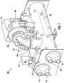
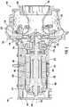
- FIG. 3a sectional view of a high speed induction motor utilized to drive a centrifugal compressor is shown.
- the high speed induction motoris substantially similar to motor 104
- the centrifugal compressoris substantially similar to compressor 102, both described above with reference to FIG. 1 .
- Motor 104is shown to include among other components, an enclosure or housing 202, a stator 204, and a rotor 206.
- the stator 204is the stationary part of the motor's electromagnetic circuit that imparts radial and axial magnetic forces on the rotor 206. In a properly aligned system, the sum of these forces is zero, or nearly zero.
- stator 204is partially encapsulated by a motor jacket 210, and both the stator 204 and the motor jacket 210 may have a substantially cylindrical shape.
- the motor jacket 210may be constructed from aluminum and may be configured to optimize heat transfer from the stator 204 to prevent overheating of the motor 104.
- the rotor 206is the rotating part of the motor's electromagnetic circuit.
- the rotor 206may be a squirrel-cage rotor, a wound rotor, a salient-pole rotor, or a cylindrical rotor.
- the rotor 206is coupled to a shaft 208.
- the shaft 208is shown to include a first end 238 and a second end 240.
- the rotor 206 and the shaft 208collectively rotate about a central axis 226 in order to transmit torque and rotation to other components and/or assemblies coupled to the motor 104.
- the second end 240 of the shaft 208is coupled to an impeller 230 of the centrifugal compressor 102 using a direct drive connection 228.
- the direct drive connection 228may include a mechanical fastener (e.g., a bolt, a pin) used to couple the shaft 208 to the impeller 230.
- Directly-driven systemsprovide advantages over gear-driven systems because they decrease friction losses and require fewer, simpler components.
- the centrifugal compressor 102can include, among other components, an inlet 242, a diffuser assembly comprised of a variable geometry diffuser (VGD) 232 and a diffuser plate 236, and a collector or scroll assembly 234.
- VGDvariable geometry diffuser
- the inlet 242can include a pipe that draws fluid (e.g., the LP refrigerant) to the impeller 230, which is a rotating set of vanes that gradually impart kinetic energy to the vapor. Downstream of the impeller 230 is the diffuser gap formed by the VGD 232 and the diffuser plate 236. The kinetic energy of the vapor is converted into pressure energy as it flows and expands through the diffuser gap and before it exits the centrifugal compressor via the collector or scroll assembly 234.
- fluide.g., the LP refrigerant
- the kinetic energy of the vaporis converted into pressure energy as it flows and expands through the diffuser gap and before it exits the centrifugal compressor via the collector or scroll assembly 234.
- the LP refrigeranthas an operating pressure of less than 400 kPa or approximately 58 psi.
- the LP refrigerantis R1233zd.
- R1233zdis a non-flammable fluorinated gas with low Global Warming Potential (GWP) relative to other refrigerants utilized in commercial chiller assemblies.
- GWPis a metric developed to allow comparisons of the global warming impacts of different gases, by quantifying how much energy the emissions of 1 ton of a gas will absorb over a given period of time, relative to the emissions of 1 ton of carbon dioxide.
- Some induction motorsutilize an interference fit to retain the stator within the housing.
- the statorcan be heated until thermal expansion creates a clearance between the inside diameter of the motor housing and the outside diameter of the stator.
- the statoris cooled until the stator contracts and a clearance is created between the motor housing and the stator.
- the clearance between the housing and the statordiminishes to zero.
- this return to equilibrium temperaturecan cause distortions in the shape (e.g., the circularity) of the stator.
- a distorted stator caused by an interference fitcan lead to unbalanced magnetic forces on the rotor,.
- designersmust overspecify bearing assemblies (i.e., they must select magnetic bearings with oversized components) in order to not exceed the rotor positioning capabilities of the magnetic bearing assemblies.
- a clearance region 222is maintained between the motor jacket 210 of the stator 204 and the motor housing 202 to avoid imperfect circularity of the housing 202 from distorting the circularity of the stator.
- a locating pin 212 or keymay be inserted through the housing 202 and the motor jacket 210, and retained within the stator 204.
- the clearance region 222 between the motor jacket 210 and the motor housing 202is controlled such that deviations in the air gap 224 never exceeds 10% of the nominal clearance.
- Nominal clearancemay be defined as perfectly concentric alignment between the stator 204 and the rotor 206 along central axis 226.
- the motor 104is also shown to include magnetic bearing assemblies 214, 216 and 218 that support the rotor 206 and shaft 208 and permit rotation of the rotor 206 and shaft 208 relative to the stator 204.
- Magnetic bearing assembliessupport a load using magnetic levitation, and thus permit relative motion with very low friction and little or no mechanical wear.
- magnetic bearing assemblies 214, 216, and 218are active magnetic bearing (AMB) assemblies.
- AMB assembliesutilize electromagnetic actuators with continuously adjusted current values to keep the rotor 206 and shaft 208 in a desired position and achieve stable levitation.
- the magnetic bearing assemblies 214 and 218may be radial bearing assemblies configured to control the position of the shaft 208 in a radial direction (i.e., perpendicular to central axis 226), while magnetic bearing assembly 216 may be a thrust bearing assembly configured to control the position of the shaft 208 in an axial direction (i.e., parallel to central axis 226).
- radial magnetic bearing assembly 214may be located proximate the first end 238 of the shaft 208
- radial magnetic bearing assembly 218may be located proximate the second end 240 of the shaft 208.
- Thrust magnetic bearing assembly 216may be located between radial bearing assemblies 214 and 218, and near the second end 240 of the shaft 208 and the impeller 230.
- the thrust magnetic bearing assembly 216By locating the thrust magnetic bearing assembly 216 near the impeller 230, when heat caused by the operation of the motor 104 causes the shaft 208 to expand, the proximity of the thrust magnetic bearing assembly 216 permits precise alignment of the impeller 230 within the compressor diffuser to achieve an optimized aerodynamic performance.
- motor 104may be semi-hermetically sealed.
- a hermetic or semi-hermetically sealed motor 104may refer to a motor that is exposed to the environment inside the compressor assembly 102 (i.e., such that the motor may be cooled by the refrigerant circulating through the chiller assembly).
- a motor that is not designed to be hermetic or semi-hermeticmay be enclosed in a separate housing, and connected to a compressor via a shaft coupling and shaft seal.
- Motor 104may be considered semi-hermetically sealed as end plate 220 may be detachably fastened to the housing 202 through the use of mechanical fasteners and seals (e.g., bolts, o-rings).
- a fully hermetically sealed compressoris one which encapsulates the motor and may include a welded enclosure.
Landscapes
- Engineering & Computer Science (AREA)
- General Engineering & Computer Science (AREA)
- Mechanical Engineering (AREA)
- Power Engineering (AREA)
- Physics & Mathematics (AREA)
- Electromagnetism (AREA)
- Thermal Sciences (AREA)
- Structures Of Non-Positive Displacement Pumps (AREA)
- Connection Of Motors, Electrical Generators, Mechanical Devices, And The Like (AREA)
- Magnetic Bearings And Hydrostatic Bearings (AREA)
Description
- The present disclosure relates generally to a high speed semi-hermetically-sealed induction motor that directly drives the centrifugal compressor of a chiller assembly. Some centrifugal compressors utilize medium pressure (MP) refrigerant, magnetic bearings, and a high speed permanent magnet motor. However, high speed permanent magnet motors often require the use of expensive rare-earth materials and a specialized variable speed drive (VSD). Impellers used with medium pressure refrigerants tend to operate at high speeds in order to achieve the required pressure rise. Utilizing low pressure (LP) refrigerant allows for the use of larger diameter impellers and, subsequently, slower operating speeds. The lower operating speed of a LP centrifugal compressor can permit the use of high-speed direct drive induction motors and a simplified VSD. The combination of induction motor technology and simplified VSDs can provide similar performance to permanent magnet motors at a reduced cost.
WO 2014/084989 A2 discloses an induction motor according to the prior art.- One implementation of the present disclosure is a sealed induction motor for a chiller assembly. The induction motor includes a stator, a rotor, and a shaft with a first end and a second end. The rotor and the shaft are configured to rotate relative to the stator. The induction motor further includes a first magnetic bearing assembly located proximate the first end of the shaft and a second magnetic bearing assembly located proximate the second end of the shaft. The first and the second magnetic bearing assemblies are configured to support the shaft and associated loads. The shaft is coupled to a centrifugal compressor using a direct drive connection.
- In some embodiments, the centrifugal compressor utilizes a low pressure refrigerant having an operating pressure of less than 400 kPa. In other embodiments, the low pressure refrigerant is R1233zd.
- In some embodiments, the first magnetic bearing assembly and the second magnetic bearing assembly include radial magnetic bearing assemblies configured to support the shaft in a radial direction. The induction motor includes a third magnetic bearing assembly configured to support the shaft in an axial direction. In other embodiments, the first, second, and third magnetic bearing assemblies are active magnetic bearing assemblies.
- Another implementation of the present disclosure is a vapor compression system. The vapor compression system includes a centrifugal compressor directly driven by a sealed induction motor, a condenser, an expansion device, and an evaporator connected in a closed refrigerant loop. The sealed induction motor includes a stator, a rotor, and a shaft with a first end and a second end. The rotor and the shaft are configured to rotate relative to the stator. The sealed induction motor further includes a first radial magnetic bearing assembly located proximate the first end of the shaft, a second radial magnetic bearing assembly located proximate the second end of the shaft, and a thrust magnetic bearing assembly. The first and second radial magnetic bearing assemblies are configured to support the shaft in a radial direction, while the thrust magnetic bearing assembly is configured to support the shaft in an axial direction.
- In some embodiments, the centrifugal compressor is a single-stage compressor with an inlet, an impeller, a diffuser, and a collector or scroll assembly.
- In some embodiments, the centrifugal compressor utilizes a low pressure refrigerant having an operating pressure of less than 400 kPa. In other embodiments, the low pressure refrigerant is R1233zd.
- In some embodiments, the thrust magnetic bearing assembly is located between the first radial magnetic bearing assembly and the second radial magnetic bearing assembly.
- Yet another implementation of the present disclosure is an induction motor for a chiller assembly according to the present invention as defined in claim 1. The induction motor includes a stator having a cylindrical shape, and a rotor coupled to a shaft. The rotor and the shaft are configured to rotate relative to the stator. The induction motor further includes magnetic bearing assemblies configured to support the rotor and a housing configured to at least partially encapsulate the stator, the rotor, the shaft, and the magnetic bearing assemblies. The stator is coupled to the motor housing using a clearance fit. The clearance fit is configured to prevent distortion of the cylindrical shape.
- In some embodiments, the shaft is coupled to a centrifugal compressor. The centrifugal compressor includes an inlet, an impeller, a diffuser, and a scroll assembly. In other embodiments, the shaft is configured to drive the impeller via a direct drive connection. In further embodiments, the centrifugal compressor utilizes a low pressure refrigerant having an operating pressure of less than 400 kPa. In still further embodiments, the low pressure refrigerant is R1233zd.
- In some embodiments, the first magnetic bearing assembly includes a radial magnetic bearing assembly or a thrust magnetic bearing assembly. In some embodiments, the induction motor includes a second magnetic bearing assembly and a third magnetic bearing assembly. In other embodiments, the first, second, and third magnetic bearing assemblies comprise active magnetic bearing assemblies
FIG. 1 is a perspective view drawing of a chiller assembly, according to some embodiments.FIG. 2 is a front elevation view drawing of the chiller assembly ofFIG. 1 , according to some embodiments.FIG. 3 is a sectional view drawing of the high-speed induction motor and centrifugal compressor of the chiller assembly ofFIG. 1 , according to some embodiments.- Referring generally to the FIGURES, a chiller assembly having a centrifugal compressor with a magnetic bearing motor compressor is shown. Referring to
FIGS. 1-2 , an example implementation of achiller assembly 100 is depicted.Chiller assembly 100 is shown to include acompressor 102 driven by amotor 104, acondenser 106, and anevaporator 108. A refrigerant is circulated throughchiller assembly 100 in a vapor compression cycle.Chiller assembly 100 can also include acontrol panel 114 to control operation of the vapor compression cycle withinchiller assembly 100. Motor 104 can be powered by a variable speed drive (VSD) 110. VSD 110 receives alternating current (AC) power having a particular fixed line voltage and fixed line frequency from an AC power source (not shown) and provides power having a variable voltage and frequency tomotor 104. Motor 104 can be any type of electric motor than can be powered by a VSD 110. For example,motor 104 can be a high speed induction motor.Compressor 102 is driven bymotor 104 to compress a refrigerant vapor received fromevaporator 108 throughsuction line 112 and to deliver refrigerant vapor to condenser 106 through adischarge line 124.Compressor 102 can be a centrifugal compressor, a screw compressor, a scroll compressor, , or any other type of suitable compressor. In the example described inFIG. 2 ,compressor 102 is a centrifugal compressor.Evaporator 108 includes an internal tube bundle (not shown), asupply line 120 and areturn line 122 for supplying and removing a process fluid to the internal tube bundle. Thesupply line 120 and thereturn line 122 can be in fluid communication with a component within a HVAC system (e.g., an air handler) via conduits that that circulate the process fluid. The process fluid is a chilled liquid for cooling a building and can be, but is not limited to, water, ethylene glycol, calcium chloride brine, sodium chloride brine, or any other suitable liquid.Evaporator 108 is configured to lower the temperature of the process fluid as the process fluid passes through the tube bundle ofevaporator 108 and exchanges heat with the refrigerant. Refrigerant vapor is formed inevaporator 108 by the refrigerant liquid delivered to theevaporator 108 exchanging heat with the process fluid and undergoing a phase change to refrigerant vapor.- Refrigerant vapor delivered from
evaporator 108 bycompressor 102 tocondenser 106 transfers heat to a fluid. Refrigerant vapor condenses to refrigerant liquid incondenser 106 as a result of heat transfer with the fluid. The refrigerant liquid fromcondenser 106 flows through an expansion device and is returned toevaporator 108 to complete the refrigerant cycle of thechiller assembly 100.Condenser 106 includes asupply line 116 and areturn line 118 for circulating fluid between thecondenser 106 and an external component of the HVAC system (e.g., a cooling tower). Fluid supplied to thecondenser 106 viareturn line 118 exchanges heat with the refrigerant in thecondenser 106 and is removed from thecondenser 106 viasupply line 116 to complete the cycle. The fluid circulating through thecondenser 106 can be water or any other suitable liquid. - Referring now to
FIG. 3 , a sectional view of a high speed induction motor utilized to drive a centrifugal compressor is shown. In some embodiments, the high speed induction motor is substantially similar tomotor 104, and the centrifugal compressor is substantially similar tocompressor 102, both described above with reference toFIG. 1 .Motor 104 is shown to include among other components, an enclosure orhousing 202, astator 204, and arotor 206. Thestator 204 is the stationary part of the motor's electromagnetic circuit that imparts radial and axial magnetic forces on therotor 206. In a properly aligned system, the sum of these forces is zero, or nearly zero. In some embodiments, thestator 204 is partially encapsulated by amotor jacket 210, and both thestator 204 and themotor jacket 210 may have a substantially cylindrical shape. Themotor jacket 210 may be constructed from aluminum and may be configured to optimize heat transfer from thestator 204 to prevent overheating of themotor 104. - The
rotor 206 is the rotating part of the motor's electromagnetic circuit. In various embodiments, therotor 206 may be a squirrel-cage rotor, a wound rotor, a salient-pole rotor, or a cylindrical rotor. Therotor 206 is coupled to ashaft 208. Theshaft 208 is shown to include afirst end 238 and asecond end 240. Therotor 206 and theshaft 208 collectively rotate about acentral axis 226 in order to transmit torque and rotation to other components and/or assemblies coupled to themotor 104. - As shown in
FIG. 3 , thesecond end 240 of theshaft 208 is coupled to animpeller 230 of thecentrifugal compressor 102 using adirect drive connection 228. In some embodiments, thedirect drive connection 228 may include a mechanical fastener (e.g., a bolt, a pin) used to couple theshaft 208 to theimpeller 230. Directly-driven systems provide advantages over gear-driven systems because they decrease friction losses and require fewer, simpler components. In addition to theimpeller 230, thecentrifugal compressor 102 can include, among other components, aninlet 242, a diffuser assembly comprised of a variable geometry diffuser (VGD) 232 and adiffuser plate 236, and a collector orscroll assembly 234. Theinlet 242 can include a pipe that draws fluid (e.g., the LP refrigerant) to theimpeller 230, which is a rotating set of vanes that gradually impart kinetic energy to the vapor. Downstream of theimpeller 230 is the diffuser gap formed by theVGD 232 and thediffuser plate 236. The kinetic energy of the vapor is converted into pressure energy as it flows and expands through the diffuser gap and before it exits the centrifugal compressor via the collector orscroll assembly 234. - In some embodiments, the LP refrigerant has an operating pressure of less than 400 kPa or approximately 58 psi. In further embodiments, the LP refrigerant is R1233zd. R1233zd is a non-flammable fluorinated gas with low Global Warming Potential (GWP) relative to other refrigerants utilized in commercial chiller assemblies. GWP is a metric developed to allow comparisons of the global warming impacts of different gases, by quantifying how much energy the emissions of 1 ton of a gas will absorb over a given period of time, relative to the emissions of 1 ton of carbon dioxide.
- Some induction motors utilize an interference fit to retain the stator within the housing. In an interference fit, the stator can be heated until thermal expansion creates a clearance between the inside diameter of the motor housing and the outside diameter of the stator. In other embodiments, the stator is cooled until the stator contracts and a clearance is created between the motor housing and the stator. Once stator is inserted into the housing and both the housing and the stator reach an equilibrium temperature, the clearance between the housing and the stator diminishes to zero. However, as the thermal expansion rates of the housing and the stator may not be identical, this return to equilibrium temperature can cause distortions in the shape (e.g., the circularity) of the stator. A distorted stator caused by an interference fit can lead to unbalanced magnetic forces on the rotor,. When the system is improperly aligned such that the sum of the forces exerted by the stator on the rotor is nonzero, designers must overspecify bearing assemblies (i.e., they must select magnetic bearings with oversized components) in order to not exceed the rotor positioning capabilities of the magnetic bearing assemblies.
- Thus, as depicted in
FIG. 3 , aclearance region 222 is maintained between themotor jacket 210 of thestator 204 and themotor housing 202 to avoid imperfect circularity of thehousing 202 from distorting the circularity of the stator. To prevent displacement and/or rotation of themotor jacket 210 and thestator 204 relative to themotor housing 202, a locatingpin 212 or key may be inserted through thehousing 202 and themotor jacket 210, and retained within thestator 204. In order to minimize unbalanced magnetic forces, it is important for thestator 204 androtor 206 to be concentric and theair gap 224, depicted inFIG. 3 , between the stator and rotor be maintained as a true cylindrical feature. Theclearance region 222 between themotor jacket 210 and themotor housing 202 is controlled such that deviations in theair gap 224 never exceeds 10% of the nominal clearance. Nominal clearance may be defined as perfectly concentric alignment between thestator 204 and therotor 206 alongcentral axis 226. - The
motor 104 is also shown to includemagnetic bearing assemblies rotor 206 andshaft 208 and permit rotation of therotor 206 andshaft 208 relative to thestator 204. Magnetic bearing assemblies support a load using magnetic levitation, and thus permit relative motion with very low friction and little or no mechanical wear. In some embodiments,magnetic bearing assemblies rotor 206 andshaft 208 in a desired position and achieve stable levitation. - The
magnetic bearing assemblies shaft 208 in a radial direction (i.e., perpendicular to central axis 226), whilemagnetic bearing assembly 216 may be a thrust bearing assembly configured to control the position of theshaft 208 in an axial direction (i.e., parallel to central axis 226). In some embodiments, radialmagnetic bearing assembly 214 may be located proximate thefirst end 238 of theshaft 208, while radialmagnetic bearing assembly 218 may be located proximate thesecond end 240 of theshaft 208. Thrustmagnetic bearing assembly 216 may be located betweenradial bearing assemblies second end 240 of theshaft 208 and theimpeller 230. By locating the thrustmagnetic bearing assembly 216 near theimpeller 230, when heat caused by the operation of themotor 104 causes theshaft 208 to expand, the proximity of the thrustmagnetic bearing assembly 216 permits precise alignment of theimpeller 230 within the compressor diffuser to achieve an optimized aerodynamic performance. - As described above,
motor 104 may be semi-hermetically sealed. A hermetic or semi-hermetically sealedmotor 104 may refer to a motor that is exposed to the environment inside the compressor assembly 102 (i.e., such that the motor may be cooled by the refrigerant circulating through the chiller assembly). By contrast, a motor that is not designed to be hermetic or semi-hermetic may be enclosed in a separate housing, and connected to a compressor via a shaft coupling and shaft seal.Motor 104 may be considered semi-hermetically sealed asend plate 220 may be detachably fastened to thehousing 202 through the use of mechanical fasteners and seals (e.g., bolts, o-rings). In comparison, a fully hermetically sealed compressor is one which encapsulates the motor and may include a welded enclosure. - The construction and arrangement of the systems and methods as shown in the various exemplary embodiments are illustrative only. Although only example embodiments have been described in detail in this disclosure, many modifications are possible (e.g., variations in sizes, dimensions, structures, shapes and proportions of the various elements, values of parameters, mounting arrangements, use of materials, colors, orientations, etc.). For example, the position of elements can be reversed or otherwise varied and the nature or number of discrete elements or positions can be altered or varied. Accordingly, such modifications are intended to be included within the scope of the present disclosure. The order or sequence of any process or method steps can be varied or re-sequenced according to alternative embodiments. Other substitutions, modifications, changes, and omissions may be made in the design, operating conditions and arrangement of the exemplary embodiments without departing from the scope of the present invention, which is defined by the appended claims.
Claims (15)
- An induction motor for a chiller assembly (100), the induction motor comprising:- a stator (204) having a cylindrical shape;- a rotor (206) coupled to a shaft (208), the rotor (206) and the shaft (208) configured to rotate relative to the stator (204);- a first magnetic bearing assembly (214, 216, 218) configured to support the rotor (206); and- a housing (202) configured to at least partially encapsulate the stator (204), the rotor (206), the shaft (208), and the first magnetic bearing assembly (214, 216, 218);wherein the stator (204) is coupled to the housing (202) using a clearance fit configured to prevent distortion of the cylindrical shape; and wherein a first clearance between the housing (202) and a motor jacket (210) coupled to the stator (204) is controlled such that deviations in a second clearance between the stator (204) and the rotor (206) do not exceed ten percent of a nominal clearance value.
- The induction motor of claim 1,
wherein the first magnetic bearing assembly (214, 216, 218) comprises at least one of a radial magnetic bearing assembly (214, 218) and a thrust magnetic bearing assembly (216). - The induction motor of claim 1 or 2,
wherein the induction motor further comprises a second magnetic bearing assembly (218, 214) and a third magnetic bearing assembly (216). - The induction motor of one of claims 1 to 3,
wherein the shaft (208) is configured to be coupled to a centrifugal compressor (102), the centrifugal compressor (102) comprising an inlet (242), an impeller (230), a diffuser, and a scroll assembly (234). - The induction motor of claim 4,
wherein the shaft (208) is configured to drive the impeller (230) via a direct drive connection (228). - The induction motor of claim 1,wherein the shaft (208) comprises a first end (238) and a second end (240), wherein the first magnetic bearing assembly (214) is located proximate the first end (238) of the shaft (208), and a second magnetic bearing assembly (218) is located proximate the second end (240) of the shaft (208), andwherein the first and the second magnetic bearing assemblies (214, 218) are configured to support the shaft (208), wherein the shaft (208) is adapted to be coupled to a centrifugal compressor (104) using a direct drive connection.
- The induction motor of claim 6,
wherein the first magnetic bearing assembly (214) and the second magnetic bearing assembly (218) comprise radial magnetic bearing assemblies (214, 218) configured to support the shaft (208) in a radial direction. - The induction motor of claim 7, further comprising a third magnetic bearing assembly (216).
- The induction motor of claim 8,
wherein the third magnetic bearing assembly (216) comprises a thrust magnetic bearing assembly (216) configured to support the shaft (208) in an axial direction. - The induction motor of claim 9,
wherein the first, second, and third magnetic bearing assemblies (214, 216, 218) comprise active magnetic bearing assemblies. - The induction motor of claim 9 or 10,
wherein the thrust magnetic bearing assembly (216) is located between the first radial magnetic bearing assembly (214) and the second radial magnetic bearing assembly (218). - A vapor compression system, comprising:- a centrifugal compressor (102) directly driven by an induction motor of one of claims 1 to 11, a condenser (106), an expansion device, and an evaporator (108) connected in a closed refrigerant loop.
- The vapor compression system of claim 12,wherein the shaft (208) is coupled to the centrifugal compressor (102), the centrifugal compressor (102) comprising an inlet (242), an impeller (230), a diffuser, and a scroll assembly (234), andwherein the shaft (208) is preferably configured to drive the impeller (230) via a direct drive connection (228).
- The vapor compression system of claim 12 or 13,
wherein the centrifugal compressor (102) is a single-stage compressor comprising an inlet, an impeller, a diffuser, and a scroll assembly. - The vapor compression system of one of the claims 12 to 14,
wherein the centrifugal compressor (102) utilizes a low pressure refrigerant having an operating pressure of less than 400 kPa, wherein the low pressure refrigerant is preferably R1233zd.
Priority Applications (1)
| Application Number | Priority Date | Filing Date | Title |
|---|---|---|---|
| EP22186643.7AEP4098884A1 (en) | 2017-03-24 | 2018-03-23 | Magnetic bearing motor compressor |
Applications Claiming Priority (3)
| Application Number | Priority Date | Filing Date | Title |
|---|---|---|---|
| US201762476343P | 2017-03-24 | 2017-03-24 | |
| US201762612065P | 2017-12-29 | 2017-12-29 | |
| PCT/US2018/024104WO2018175938A1 (en) | 2017-03-24 | 2018-03-23 | Magnetic bearing motor compressor |
Related Child Applications (1)
| Application Number | Title | Priority Date | Filing Date |
|---|---|---|---|
| EP22186643.7ADivisionEP4098884A1 (en) | 2017-03-24 | 2018-03-23 | Magnetic bearing motor compressor |
Publications (2)
| Publication Number | Publication Date |
|---|---|
| EP3601804A1 EP3601804A1 (en) | 2020-02-05 |
| EP3601804B1true EP3601804B1 (en) | 2022-08-03 |
Family
ID=61913677
Family Applications (2)
| Application Number | Title | Priority Date | Filing Date |
|---|---|---|---|
| EP22186643.7APendingEP4098884A1 (en) | 2017-03-24 | 2018-03-23 | Magnetic bearing motor compressor |
| EP18716854.7AActiveEP3601804B1 (en) | 2017-03-24 | 2018-03-23 | Magnetic bearing motor compressor |
Family Applications Before (1)
| Application Number | Title | Priority Date | Filing Date |
|---|---|---|---|
| EP22186643.7APendingEP4098884A1 (en) | 2017-03-24 | 2018-03-23 | Magnetic bearing motor compressor |
Country Status (7)
| Country | Link |
|---|---|
| US (2) | US10666113B2 (en) |
| EP (2) | EP4098884A1 (en) |
| JP (3) | JP7132238B2 (en) |
| KR (2) | KR102697513B1 (en) |
| CN (2) | CN110475977B (en) |
| TW (1) | TWI703267B (en) |
| WO (1) | WO2018175938A1 (en) |
Families Citing this family (10)
| Publication number | Priority date | Publication date | Assignee | Title |
|---|---|---|---|---|
| CN110475977B (en) | 2017-03-24 | 2022-04-26 | 江森自控科技公司 | Magnetic bearing motor compressor |
| KR102624557B1 (en)* | 2018-10-19 | 2024-01-15 | 엘지전자 주식회사 | Moter |
| CN111486112A (en)* | 2019-01-29 | 2020-08-04 | 青岛海尔智能技术研发有限公司 | Magnetic suspension centrifugal compressor and air conditioning system |
| EP3966454B1 (en)* | 2019-05-10 | 2024-06-26 | Carrier Corporation | Compressor with thrust control |
| KR20210129962A (en)* | 2020-04-21 | 2021-10-29 | 엘지전자 주식회사 | Compressor and Chiller system having the same |
| US12009696B2 (en)* | 2021-05-24 | 2024-06-11 | Hamilton Sundstrand Corporation | Two phase cooling for electric machine |
| CN113669273B (en)* | 2021-08-11 | 2025-09-23 | 鑫磊压缩机股份有限公司 | A magnetic levitation centrifuge blower |
| US20240255024A1 (en)* | 2023-01-26 | 2024-08-01 | Hamilton Sundstrand Corporation | Aircraft environmental control system vapor cycle compressor with motor-integrated active magnetic bearings |
| TWI881500B (en)* | 2023-10-20 | 2025-04-21 | 復盛股份有限公司 | Motor cooling system of compressor |
| CN118232609A (en)* | 2024-03-22 | 2024-06-21 | 江西江特高新装备有限公司 | Air-cooled magnetic suspension motor and fan with same |
Family Cites Families (61)
| Publication number | Priority date | Publication date | Assignee | Title |
|---|---|---|---|---|
| IL109967A (en)* | 1993-06-15 | 1997-07-13 | Multistack Int Ltd | Compressor |
| JP3173267B2 (en) | 1993-12-28 | 2001-06-04 | 松下電器産業株式会社 | Scroll compressor |
| JP3124678B2 (en)* | 1994-03-16 | 2001-01-15 | アルプス電気株式会社 | motor |
| CH689808A5 (en) | 1994-05-25 | 1999-11-30 | Mecos Traxler Ag | A method for contact-free supporting objects and device for performing this method. |
| JP3239787B2 (en) | 1997-01-30 | 2001-12-17 | 安藤電気株式会社 | IC socket |
| US5924847A (en)* | 1997-08-11 | 1999-07-20 | Mainstream Engineering Corp. | Magnetic bearing centrifugal refrigeration compressor and refrigerant having minimum specific enthalpy rise |
| US6463748B1 (en) | 1999-12-06 | 2002-10-15 | Mainstream Engineering Corporation | Apparatus and method for controlling a magnetic bearing centrifugal chiller |
| PT1246348E (en) | 2001-03-30 | 2011-06-01 | Sanyo Electric Co | Synchronous induction motor and manufacturing method and drive unit for the same, and hermetic electric compressor |
| TW571487B (en) | 2001-10-16 | 2004-01-11 | Hitachi Air Conditioning Sys | Self-starting synchronous motor and compressor using the same |
| US20030084888A1 (en)* | 2001-11-08 | 2003-05-08 | Lebold Robert S | Supercharger type compressor/generator with magnetically loaded composite rotor |
| US20040170497A1 (en) | 2003-02-27 | 2004-09-02 | Daniel Snyder | Beltless high velocity air blower |
| EP1516417B1 (en) | 2003-07-09 | 2010-11-03 | Panasonic Corporation | Syncronous induction motor and electric hermetic compressor using the same |
| JP4243996B2 (en)* | 2003-08-21 | 2009-03-25 | 株式会社荏原製作所 | Turbo vacuum pump and semiconductor manufacturing apparatus equipped with the turbo vacuum pump |
| KR100530692B1 (en)* | 2004-02-18 | 2005-11-24 | (주)앤틀 | Turbo machine |
| JP2006183499A (en) | 2004-12-27 | 2006-07-13 | Hitachi Ltd | Positive displacement compressor |
| DE102005032204A1 (en)* | 2005-07-09 | 2007-01-25 | Zf Friedrichshafen Ag | Electric machine for a transmission of a motor vehicle and device for cooling the electric machine |
| WO2007035700A2 (en)* | 2005-09-19 | 2007-03-29 | Ingersoll-Rand Company | Multi-stage compression system including variable speed motors |
| JP4571593B2 (en)* | 2006-01-30 | 2010-10-27 | アルファナテクノロジー株式会社 | motor |
| KR100927926B1 (en) | 2006-03-30 | 2009-11-19 | 미쓰비시덴키 가부시키가이샤 | Single Phase Motors and Hermetic Compressors |
| KR20080083334A (en) | 2006-12-01 | 2008-09-17 | 마쯔시다덴기산교 가부시키가이샤 | Hermetic compressor and its manufacturing method |
| US8597001B2 (en)* | 2007-05-14 | 2013-12-03 | Sundyne Corporation | Electric machine with air cooling system |
| DE102007060654A1 (en)* | 2007-12-15 | 2009-06-18 | Abb Technology Ag | Method for producing a stator housing unit |
| KR101570235B1 (en) | 2007-12-31 | 2015-11-18 | 존슨 컨트롤스 테크놀러지 컴퍼니 | Method and system for rotor cooling |
| US8319388B2 (en) | 2008-01-25 | 2012-11-27 | Mitsubishi Electric Corporation | Induction motor and hermetic compressor |
| US8616855B2 (en) | 2008-02-01 | 2013-12-31 | Carrier Corporation | Integral compressor motor and refrigerant/oil heater apparatus and method |
| US7856834B2 (en)* | 2008-02-20 | 2010-12-28 | Trane International Inc. | Centrifugal compressor assembly and method |
| CN102099987B (en) | 2008-08-05 | 2014-06-11 | 三菱电机株式会社 | Induction motor and enclosed compressor |
| US8067865B2 (en)* | 2008-10-28 | 2011-11-29 | Caterpillar Inc. | Electric motor/generator low hydraulic resistance cooling mechanism |
| DE102009046482A1 (en)* | 2009-11-06 | 2011-05-12 | Man Diesel & Turbo Se | Electric machine |
| EP2390511A1 (en)* | 2010-05-25 | 2011-11-30 | Siemens Aktiengesellschaft | Additional support for AMB supported rotors by means of permanent magnet bearings |
| EP2599190B1 (en) | 2010-07-28 | 2016-08-17 | Danfoss A/S | Refrigerant compressor magnetic bearing |
| WO2012057885A1 (en)* | 2010-10-27 | 2012-05-03 | Dresser-Rand Company | Multiple motor drivers for a hermetically-sealed motor-compressor system |
| US9212667B2 (en) | 2010-12-22 | 2015-12-15 | Danfoss A/S | Variable-speed oil-free refrigerant centrifugal compressor with variable geometry diffuser |
| JP5591099B2 (en) | 2010-12-28 | 2014-09-17 | 三菱電機株式会社 | Compressor and refrigeration cycle equipment |
| US20140125269A1 (en) | 2011-02-25 | 2014-05-08 | Whirlpool S.A. | Winding switching circuit and thermal protection for dual voltage hermetic induction motor of hermetic cooling compressor |
| EP2678569B1 (en)* | 2011-07-15 | 2015-11-18 | Carrier Corporation | Compressor clearance control |
| US10260507B2 (en)* | 2011-08-23 | 2019-04-16 | Moog Inc. | Magnetically coupled pump assembly |
| JP5240336B2 (en) | 2011-09-26 | 2013-07-17 | ダイキン工業株式会社 | Magnetic bearing and compressor using the same |
| JP5218636B1 (en) | 2011-12-28 | 2013-06-26 | ダイキン工業株式会社 | Magnetic bearing device and compressor |
| US8681496B2 (en)* | 2012-01-25 | 2014-03-25 | Toyota Motor Engineering & Manufacturing North America, Inc. | Cooling apparatuses, electronic device assemblies, and cooling assemblies using magnetic shape memory members |
| WO2013133832A2 (en) | 2012-03-08 | 2013-09-12 | Danfoss Turbocor Compressors B.V. | High pressure ratio multi-stage centrifugal compressor |
| EP2677176B1 (en)* | 2012-06-22 | 2018-12-19 | Skf Magnetic Mechatronics | Compact electric centrifugal compressor |
| EP2677177B1 (en)* | 2012-06-22 | 2020-10-14 | Skf Magnetic Mechatronics | Electric centrifugal compressor for vehicles |
| JP5700033B2 (en) | 2012-09-12 | 2015-04-15 | ダイキン工業株式会社 | Magnetic bearing |
| EP3022833B1 (en)* | 2012-11-28 | 2017-12-06 | Johnson Controls Technology Company | Cooling circuit and motor cooling method for a compressor motor |
| US9621013B2 (en)* | 2013-03-15 | 2017-04-11 | Ingersoll-Rand Company | Rotating machine with magnetic bearing |
| DE102013213435A1 (en)* | 2013-07-09 | 2015-01-15 | Schaeffler Technologies Gmbh & Co. Kg | Cooling system for a dynamoelectric machine |
| DE102013217261A1 (en)* | 2013-08-29 | 2015-03-05 | Robert Bosch Gmbh | compressor |
| CN104454989B (en) | 2013-09-13 | 2017-03-29 | 珠海格力节能环保制冷技术研究中心有限公司 | Magnetic suspension bearing and centrifugal compressor |
| US10323628B2 (en) | 2013-11-07 | 2019-06-18 | Gas Technology Institute | Free piston linear motor compressor and associated systems of operation |
| JP6230441B2 (en) | 2014-02-20 | 2017-11-15 | 三菱電機株式会社 | Single-phase induction motor, hermetic compressor, and refrigeration cycle apparatus |
| WO2015160881A1 (en)* | 2014-04-15 | 2015-10-22 | Johnson Controls Technology Company | Centrifugal chiller system |
| JP6487163B2 (en)* | 2014-07-31 | 2019-03-20 | 三菱重工サーマルシステムズ株式会社 | Turbo refrigerator |
| EP3334984A1 (en)* | 2015-08-11 | 2018-06-20 | Carrier Corporation | Low-capacity, low-gwp, hvac system |
| CN105332932B (en)* | 2015-12-09 | 2017-12-08 | 南京磁谷科技有限公司 | A kind of explosion-proof leakage-proof magnetic suspension blower fan |
| CN108368881B (en)* | 2015-12-10 | 2019-12-27 | 大金工业株式会社 | Magnetic bearing device and compressor |
| CN206035859U (en)* | 2016-09-21 | 2017-03-22 | 重庆江增船舶重工有限公司 | High -speed asynchronous machine of magnetic suspension bearing directly drives centrifugal compressor |
| JP2018141708A (en)* | 2017-02-28 | 2018-09-13 | 三菱重工サーマルシステムズ株式会社 | Temperature prediction device, magnetic bearing loading compressor, temperature prediction method and program |
| CN110475977B (en)* | 2017-03-24 | 2022-04-26 | 江森自控科技公司 | Magnetic bearing motor compressor |
| JP6447662B2 (en)* | 2017-05-09 | 2019-01-09 | ダイキン工業株式会社 | Electric motor system and turbo compressor provided with the same |
| AT520633B1 (en)* | 2018-02-08 | 2019-06-15 | Miba Sinter Austria Gmbh | Pump arrangement, axial flow machine and compressor |
- 2018
- 2018-03-23CNCN201880019803.8Apatent/CN110475977B/enactiveActive
- 2018-03-23KRKR1020237027056Apatent/KR102697513B1/enactiveActive
- 2018-03-23KRKR1020197031302Apatent/KR102567192B1/enactiveActive
- 2018-03-23TWTW107110147Apatent/TWI703267B/enactive
- 2018-03-23JPJP2019551577Apatent/JP7132238B2/enactiveActive
- 2018-03-23EPEP22186643.7Apatent/EP4098884A1/enactivePending
- 2018-03-23CNCN202210424760.XApatent/CN114876825A/enactivePending
- 2018-03-23EPEP18716854.7Apatent/EP3601804B1/enactiveActive
- 2018-03-23WOPCT/US2018/024104patent/WO2018175938A1/ennot_activeCeased
- 2018-11-06USUS16/182,410patent/US10666113B2/enactiveActive
- 2020
- 2020-04-29USUS16/861,865patent/US11757328B2/enactiveActive
- 2022
- 2022-08-25JPJP2022133761Apatent/JP2022177003A/enactivePending
- 2024
- 2024-07-11JPJP2024111707Apatent/JP2024156697A/enactivePending
Also Published As
| Publication number | Publication date |
|---|---|
| CN114876825A (en) | 2022-08-09 |
| US10666113B2 (en) | 2020-05-26 |
| KR20230120677A (en) | 2023-08-17 |
| US20200259394A1 (en) | 2020-08-13 |
| US20190074749A1 (en) | 2019-03-07 |
| WO2018175938A1 (en) | 2018-09-27 |
| CN110475977A (en) | 2019-11-19 |
| JP2024156697A (en) | 2024-11-06 |
| JP2020514625A (en) | 2020-05-21 |
| CN110475977B (en) | 2022-04-26 |
| KR102697513B1 (en) | 2024-08-26 |
| TWI703267B (en) | 2020-09-01 |
| EP3601804A1 (en) | 2020-02-05 |
| TW201839263A (en) | 2018-11-01 |
| KR102567192B1 (en) | 2023-08-17 |
| JP7132238B2 (en) | 2022-09-06 |
| EP4098884A1 (en) | 2022-12-07 |
| JP2022177003A (en) | 2022-11-30 |
| KR20190129116A (en) | 2019-11-19 |
| US11757328B2 (en) | 2023-09-12 |
Similar Documents
| Publication | Publication Date | Title |
|---|---|---|
| US11757328B2 (en) | Magnetic bearing motor compressor | |
| US9395111B2 (en) | Motor cooling method for a compressor | |
| KR102562950B1 (en) | Liquid injection nozzle for chiller motor | |
| CN110447162A (en) | cooler motor with cooling flow path | |
| EP4034768B1 (en) | Integrated motor-compressor unit having a cooling circuit and a depressurization system configured to reduce pressure of the cooling fluid | |
| US11480215B2 (en) | Self-centering auxiliary bearings in a magnetic bearing cartridge | |
| US20250027511A1 (en) | Integrated motor-compressor unit having a cooling circuit and a depressurization system configured to reduce pressure of the cooling fluid | |
| EA043513B1 (en) | INTEGRATED COMPRESSOR UNIT WITH ENGINE, HAVING A COOLING CIRCUIT AND A PRESSURE REDUCING SYSTEM, CAPABLE OF REDUCING THE PRESSURE OF THE COOLING FLUID | |
| CN119585531A (en) | Turbo compressor and turbo refrigerator equipped with the same |
Legal Events
| Date | Code | Title | Description |
|---|---|---|---|
| STAA | Information on the status of an ep patent application or granted ep patent | Free format text:STATUS: UNKNOWN | |
| STAA | Information on the status of an ep patent application or granted ep patent | Free format text:STATUS: THE INTERNATIONAL PUBLICATION HAS BEEN MADE | |
| PUAI | Public reference made under article 153(3) epc to a published international application that has entered the european phase | Free format text:ORIGINAL CODE: 0009012 | |
| STAA | Information on the status of an ep patent application or granted ep patent | Free format text:STATUS: REQUEST FOR EXAMINATION WAS MADE | |
| 17P | Request for examination filed | Effective date:20191024 | |
| AK | Designated contracting states | Kind code of ref document:A1 Designated state(s):AL AT BE BG CH CY CZ DE DK EE ES FI FR GB GR HR HU IE IS IT LI LT LU LV MC MK MT NL NO PL PT RO RS SE SI SK SM TR | |
| GRAP | Despatch of communication of intention to grant a patent | Free format text:ORIGINAL CODE: EPIDOSNIGR1 | |
| STAA | Information on the status of an ep patent application or granted ep patent | Free format text:STATUS: GRANT OF PATENT IS INTENDED | |
| INTG | Intention to grant announced | Effective date:20220207 | |
| GRAS | Grant fee paid | Free format text:ORIGINAL CODE: EPIDOSNIGR3 | |
| GRAA | (expected) grant | Free format text:ORIGINAL CODE: 0009210 | |
| STAA | Information on the status of an ep patent application or granted ep patent | Free format text:STATUS: THE PATENT HAS BEEN GRANTED | |
| RAP1 | Party data changed (applicant data changed or rights of an application transferred) | Owner name:JOHNSON CONTROLS TYCO IP HOLDINGS LLP | |
| AK | Designated contracting states | Kind code of ref document:B1 Designated state(s):AL AT BE BG CH CY CZ DE DK EE ES FI FR GB GR HR HU IE IS IT LI LT LU LV MC MK MT NL NO PL PT RO RS SE SI SK SM TR | |
| REG | Reference to a national code | Ref country code:AT Ref legal event code:REF Ref document number:1508956 Country of ref document:AT Kind code of ref document:T Effective date:20220815 Ref country code:CH Ref legal event code:EP | |
| REG | Reference to a national code | Ref country code:DE Ref legal event code:R096 Ref document number:602018038727 Country of ref document:DE | |
| REG | Reference to a national code | Ref country code:IE Ref legal event code:FG4D | |
| REG | Reference to a national code | Ref country code:LT Ref legal event code:MG9D | |
| REG | Reference to a national code | Ref country code:NL Ref legal event code:MP Effective date:20220803 | |
| PG25 | Lapsed in a contracting state [announced via postgrant information from national office to epo] | Ref country code:SE Free format text:LAPSE BECAUSE OF FAILURE TO SUBMIT A TRANSLATION OF THE DESCRIPTION OR TO PAY THE FEE WITHIN THE PRESCRIBED TIME-LIMIT Effective date:20220803 Ref country code:RS Free format text:LAPSE BECAUSE OF FAILURE TO SUBMIT A TRANSLATION OF THE DESCRIPTION OR TO PAY THE FEE WITHIN THE PRESCRIBED TIME-LIMIT Effective date:20220803 Ref country code:PT Free format text:LAPSE BECAUSE OF FAILURE TO SUBMIT A TRANSLATION OF THE DESCRIPTION OR TO PAY THE FEE WITHIN THE PRESCRIBED TIME-LIMIT Effective date:20221205 Ref country code:NO Free format text:LAPSE BECAUSE OF FAILURE TO SUBMIT A TRANSLATION OF THE DESCRIPTION OR TO PAY THE FEE WITHIN THE PRESCRIBED TIME-LIMIT Effective date:20221103 Ref country code:NL Free format text:LAPSE BECAUSE OF FAILURE TO SUBMIT A TRANSLATION OF THE DESCRIPTION OR TO PAY THE FEE WITHIN THE PRESCRIBED TIME-LIMIT Effective date:20220803 Ref country code:LV Free format text:LAPSE BECAUSE OF FAILURE TO SUBMIT A TRANSLATION OF THE DESCRIPTION OR TO PAY THE FEE WITHIN THE PRESCRIBED TIME-LIMIT Effective date:20220803 Ref country code:LT Free format text:LAPSE BECAUSE OF FAILURE TO SUBMIT A TRANSLATION OF THE DESCRIPTION OR TO PAY THE FEE WITHIN THE PRESCRIBED TIME-LIMIT Effective date:20220803 Ref country code:FI Free format text:LAPSE BECAUSE OF FAILURE TO SUBMIT A TRANSLATION OF THE DESCRIPTION OR TO PAY THE FEE WITHIN THE PRESCRIBED TIME-LIMIT Effective date:20220803 Ref country code:ES Free format text:LAPSE BECAUSE OF FAILURE TO SUBMIT A TRANSLATION OF THE DESCRIPTION OR TO PAY THE FEE WITHIN THE PRESCRIBED TIME-LIMIT Effective date:20220803 | |
| REG | Reference to a national code | Ref country code:AT Ref legal event code:MK05 Ref document number:1508956 Country of ref document:AT Kind code of ref document:T Effective date:20220803 | |
| PG25 | Lapsed in a contracting state [announced via postgrant information from national office to epo] | Ref country code:PL Free format text:LAPSE BECAUSE OF FAILURE TO SUBMIT A TRANSLATION OF THE DESCRIPTION OR TO PAY THE FEE WITHIN THE PRESCRIBED TIME-LIMIT Effective date:20220803 Ref country code:IS Free format text:LAPSE BECAUSE OF FAILURE TO SUBMIT A TRANSLATION OF THE DESCRIPTION OR TO PAY THE FEE WITHIN THE PRESCRIBED TIME-LIMIT Effective date:20221203 Ref country code:HR Free format text:LAPSE BECAUSE OF FAILURE TO SUBMIT A TRANSLATION OF THE DESCRIPTION OR TO PAY THE FEE WITHIN THE PRESCRIBED TIME-LIMIT Effective date:20220803 Ref country code:GR Free format text:LAPSE BECAUSE OF FAILURE TO SUBMIT A TRANSLATION OF THE DESCRIPTION OR TO PAY THE FEE WITHIN THE PRESCRIBED TIME-LIMIT Effective date:20221104 | |
| PG25 | Lapsed in a contracting state [announced via postgrant information from national office to epo] | Ref country code:SM Free format text:LAPSE BECAUSE OF FAILURE TO SUBMIT A TRANSLATION OF THE DESCRIPTION OR TO PAY THE FEE WITHIN THE PRESCRIBED TIME-LIMIT Effective date:20220803 Ref country code:RO Free format text:LAPSE BECAUSE OF FAILURE TO SUBMIT A TRANSLATION OF THE DESCRIPTION OR TO PAY THE FEE WITHIN THE PRESCRIBED TIME-LIMIT Effective date:20220803 Ref country code:DK Free format text:LAPSE BECAUSE OF FAILURE TO SUBMIT A TRANSLATION OF THE DESCRIPTION OR TO PAY THE FEE WITHIN THE PRESCRIBED TIME-LIMIT Effective date:20220803 Ref country code:CZ Free format text:LAPSE BECAUSE OF FAILURE TO SUBMIT A TRANSLATION OF THE DESCRIPTION OR TO PAY THE FEE WITHIN THE PRESCRIBED TIME-LIMIT Effective date:20220803 Ref country code:AT Free format text:LAPSE BECAUSE OF FAILURE TO SUBMIT A TRANSLATION OF THE DESCRIPTION OR TO PAY THE FEE WITHIN THE PRESCRIBED TIME-LIMIT Effective date:20220803 | |
| REG | Reference to a national code | Ref country code:DE Ref legal event code:R097 Ref document number:602018038727 Country of ref document:DE | |
| PG25 | Lapsed in a contracting state [announced via postgrant information from national office to epo] | Ref country code:SK Free format text:LAPSE BECAUSE OF FAILURE TO SUBMIT A TRANSLATION OF THE DESCRIPTION OR TO PAY THE FEE WITHIN THE PRESCRIBED TIME-LIMIT Effective date:20220803 Ref country code:EE Free format text:LAPSE BECAUSE OF FAILURE TO SUBMIT A TRANSLATION OF THE DESCRIPTION OR TO PAY THE FEE WITHIN THE PRESCRIBED TIME-LIMIT Effective date:20220803 | |
| PLBE | No opposition filed within time limit | Free format text:ORIGINAL CODE: 0009261 | |
| STAA | Information on the status of an ep patent application or granted ep patent | Free format text:STATUS: NO OPPOSITION FILED WITHIN TIME LIMIT | |
| PG25 | Lapsed in a contracting state [announced via postgrant information from national office to epo] | Ref country code:AL Free format text:LAPSE BECAUSE OF FAILURE TO SUBMIT A TRANSLATION OF THE DESCRIPTION OR TO PAY THE FEE WITHIN THE PRESCRIBED TIME-LIMIT Effective date:20220803 | |
| 26N | No opposition filed | Effective date:20230504 | |
| PG25 | Lapsed in a contracting state [announced via postgrant information from national office to epo] | Ref country code:SI Free format text:LAPSE BECAUSE OF FAILURE TO SUBMIT A TRANSLATION OF THE DESCRIPTION OR TO PAY THE FEE WITHIN THE PRESCRIBED TIME-LIMIT Effective date:20220803 | |
| PG25 | Lapsed in a contracting state [announced via postgrant information from national office to epo] | Ref country code:MC Free format text:LAPSE BECAUSE OF FAILURE TO SUBMIT A TRANSLATION OF THE DESCRIPTION OR TO PAY THE FEE WITHIN THE PRESCRIBED TIME-LIMIT Effective date:20220803 | |
| REG | Reference to a national code | Ref country code:CH Ref legal event code:PL | |
| REG | Reference to a national code | Ref country code:BE Ref legal event code:MM Effective date:20230331 | |
| PG25 | Lapsed in a contracting state [announced via postgrant information from national office to epo] | Ref country code:LU Free format text:LAPSE BECAUSE OF NON-PAYMENT OF DUE FEES Effective date:20230323 | |
| REG | Reference to a national code | Ref country code:IE Ref legal event code:MM4A | |
| PG25 | Lapsed in a contracting state [announced via postgrant information from national office to epo] | Ref country code:LI Free format text:LAPSE BECAUSE OF NON-PAYMENT OF DUE FEES Effective date:20230331 Ref country code:IE Free format text:LAPSE BECAUSE OF NON-PAYMENT OF DUE FEES Effective date:20230323 Ref country code:CH Free format text:LAPSE BECAUSE OF NON-PAYMENT OF DUE FEES Effective date:20230331 | |
| PG25 | Lapsed in a contracting state [announced via postgrant information from national office to epo] | Ref country code:BE Free format text:LAPSE BECAUSE OF NON-PAYMENT OF DUE FEES Effective date:20230331 | |
| PGFP | Annual fee paid to national office [announced via postgrant information from national office to epo] | Ref country code:GB Payment date:20240319 Year of fee payment:7 | |
| PG25 | Lapsed in a contracting state [announced via postgrant information from national office to epo] | Ref country code:IT Free format text:LAPSE BECAUSE OF FAILURE TO SUBMIT A TRANSLATION OF THE DESCRIPTION OR TO PAY THE FEE WITHIN THE PRESCRIBED TIME-LIMIT Effective date:20220803 | |
| PG25 | Lapsed in a contracting state [announced via postgrant information from national office to epo] | Ref country code:BG Free format text:LAPSE BECAUSE OF FAILURE TO SUBMIT A TRANSLATION OF THE DESCRIPTION OR TO PAY THE FEE WITHIN THE PRESCRIBED TIME-LIMIT Effective date:20220803 | |
| PG25 | Lapsed in a contracting state [announced via postgrant information from national office to epo] | Ref country code:BG Free format text:LAPSE BECAUSE OF FAILURE TO SUBMIT A TRANSLATION OF THE DESCRIPTION OR TO PAY THE FEE WITHIN THE PRESCRIBED TIME-LIMIT Effective date:20220803 | |
| PGFP | Annual fee paid to national office [announced via postgrant information from national office to epo] | Ref country code:DE Payment date:20250327 Year of fee payment:8 | |
| PGFP | Annual fee paid to national office [announced via postgrant information from national office to epo] | Ref country code:FR Payment date:20250324 Year of fee payment:8 | |
| PG25 | Lapsed in a contracting state [announced via postgrant information from national office to epo] | Ref country code:CY Free format text:LAPSE BECAUSE OF FAILURE TO SUBMIT A TRANSLATION OF THE DESCRIPTION OR TO PAY THE FEE WITHIN THE PRESCRIBED TIME-LIMIT; INVALID AB INITIO Effective date:20180323 | |
| PG25 | Lapsed in a contracting state [announced via postgrant information from national office to epo] | Ref country code:HU Free format text:LAPSE BECAUSE OF FAILURE TO SUBMIT A TRANSLATION OF THE DESCRIPTION OR TO PAY THE FEE WITHIN THE PRESCRIBED TIME-LIMIT; INVALID AB INITIO Effective date:20180323 |