EP3601722B1 - Mitigating corrosion of carbon steel tubing and surface scaling deposition in oilfield applications - Google Patents
Mitigating corrosion of carbon steel tubing and surface scaling deposition in oilfield applicationsDownload PDFInfo
- Publication number
- EP3601722B1 EP3601722B1EP18716835.6AEP18716835AEP3601722B1EP 3601722 B1EP3601722 B1EP 3601722B1EP 18716835 AEP18716835 AEP 18716835AEP 3601722 B1EP3601722 B1EP 3601722B1
- Authority
- EP
- European Patent Office
- Prior art keywords
- oil
- carbon steel
- based liquid
- steel tubing
- sour gas
- Prior art date
- Legal status (The legal status is an assumption and is not a legal conclusion. Google has not performed a legal analysis and makes no representation as to the accuracy of the status listed.)
- Active
Links
Images

Classifications
- E—FIXED CONSTRUCTIONS
- E21—EARTH OR ROCK DRILLING; MINING
- E21B—EARTH OR ROCK DRILLING; OBTAINING OIL, GAS, WATER, SOLUBLE OR MELTABLE MATERIALS OR A SLURRY OF MINERALS FROM WELLS
- E21B41/00—Equipment or details not covered by groups E21B15/00 - E21B40/00
- E21B41/02—Equipment or details not covered by groups E21B15/00 - E21B40/00 in situ inhibition of corrosion in boreholes or wells
- C—CHEMISTRY; METALLURGY
- C09—DYES; PAINTS; POLISHES; NATURAL RESINS; ADHESIVES; COMPOSITIONS NOT OTHERWISE PROVIDED FOR; APPLICATIONS OF MATERIALS NOT OTHERWISE PROVIDED FOR
- C09K—MATERIALS FOR MISCELLANEOUS APPLICATIONS, NOT PROVIDED FOR ELSEWHERE
- C09K8/00—Compositions for drilling of boreholes or wells; Compositions for treating boreholes or wells, e.g. for completion or for remedial operations
- C09K8/52—Compositions for preventing, limiting or eliminating depositions, e.g. for cleaning
- C09K8/528—Compositions for preventing, limiting or eliminating depositions, e.g. for cleaning inorganic depositions, e.g. sulfates or carbonates
- C—CHEMISTRY; METALLURGY
- C09—DYES; PAINTS; POLISHES; NATURAL RESINS; ADHESIVES; COMPOSITIONS NOT OTHERWISE PROVIDED FOR; APPLICATIONS OF MATERIALS NOT OTHERWISE PROVIDED FOR
- C09K—MATERIALS FOR MISCELLANEOUS APPLICATIONS, NOT PROVIDED FOR ELSEWHERE
- C09K8/00—Compositions for drilling of boreholes or wells; Compositions for treating boreholes or wells, e.g. for completion or for remedial operations
- C09K8/54—Compositions for in situ inhibition of corrosion in boreholes or wells
- C—CHEMISTRY; METALLURGY
- C23—COATING METALLIC MATERIAL; COATING MATERIAL WITH METALLIC MATERIAL; CHEMICAL SURFACE TREATMENT; DIFFUSION TREATMENT OF METALLIC MATERIAL; COATING BY VACUUM EVAPORATION, BY SPUTTERING, BY ION IMPLANTATION OR BY CHEMICAL VAPOUR DEPOSITION, IN GENERAL; INHIBITING CORROSION OF METALLIC MATERIAL OR INCRUSTATION IN GENERAL
- C23F—NON-MECHANICAL REMOVAL OF METALLIC MATERIAL FROM SURFACE; INHIBITING CORROSION OF METALLIC MATERIAL OR INCRUSTATION IN GENERAL; MULTI-STEP PROCESSES FOR SURFACE TREATMENT OF METALLIC MATERIAL INVOLVING AT LEAST ONE PROCESS PROVIDED FOR IN CLASS C23 AND AT LEAST ONE PROCESS COVERED BY SUBCLASS C21D OR C22F OR CLASS C25
- C23F15/00—Other methods of preventing corrosion or incrustation
- E—FIXED CONSTRUCTIONS
- E21—EARTH OR ROCK DRILLING; MINING
- E21B—EARTH OR ROCK DRILLING; OBTAINING OIL, GAS, WATER, SOLUBLE OR MELTABLE MATERIALS OR A SLURRY OF MINERALS FROM WELLS
- E21B17/00—Drilling rods or pipes; Flexible drill strings; Kellies; Drill collars; Sucker rods; Cables; Casings; Tubings
- E21B17/02—Couplings; joints
- E21B17/08—Casing joints
- E—FIXED CONSTRUCTIONS
- E21—EARTH OR ROCK DRILLING; MINING
- E21B—EARTH OR ROCK DRILLING; OBTAINING OIL, GAS, WATER, SOLUBLE OR MELTABLE MATERIALS OR A SLURRY OF MINERALS FROM WELLS
- E21B37/00—Methods or apparatus for cleaning boreholes or wells
- E21B37/06—Methods or apparatus for cleaning boreholes or wells using chemical means for preventing or limiting, e.g. eliminating, the deposition of paraffins or like substances
- E—FIXED CONSTRUCTIONS
- E21—EARTH OR ROCK DRILLING; MINING
- E21B—EARTH OR ROCK DRILLING; OBTAINING OIL, GAS, WATER, SOLUBLE OR MELTABLE MATERIALS OR A SLURRY OF MINERALS FROM WELLS
- E21B43/00—Methods or apparatus for obtaining oil, gas, water, soluble or meltable materials or a slurry of minerals from wells
- E21B43/34—Arrangements for separating materials produced by the well
- E21B43/40—Separation associated with re-injection of separated materials
- F—MECHANICAL ENGINEERING; LIGHTING; HEATING; WEAPONS; BLASTING
- F16—ENGINEERING ELEMENTS AND UNITS; GENERAL MEASURES FOR PRODUCING AND MAINTAINING EFFECTIVE FUNCTIONING OF MACHINES OR INSTALLATIONS; THERMAL INSULATION IN GENERAL
- F16L—PIPES; JOINTS OR FITTINGS FOR PIPES; SUPPORTS FOR PIPES, CABLES OR PROTECTIVE TUBING; MEANS FOR THERMAL INSULATION IN GENERAL
- F16L58/00—Protection of pipes or pipe fittings against corrosion or incrustation
- F16L58/02—Protection of pipes or pipe fittings against corrosion or incrustation by means of internal or external coatings
- F16L58/04—Coatings characterised by the materials used
Definitions
- This documentrelates to methods for mitigating corrosion of carbon steel tubing and surface scaling deposition on carbon steel tubing in oilfield applications, particularly in sour gas wells.
- Carbon steel tubinghas been widely used as well completion material in sour gas wells in oilfield applications. Despite the cost effectiveness of this tubing, however, the failure of carbon steel tubing due to corrosion and surface scaling deposition downhole are two persistent issues in sour gas wells. This failure can lead to leaking, restriction of downhole surveillance and intervention, significant losses of gas production, and costly damage. While continuous injection of chemicals such as corrosion and scale inhibitors has been used to reduce corrosion and scaling in carbon steel tubing, chemical treatment is not always effective in sour gas wells given the elevated temperatures and high concentration of hydrogen sulfide. In addition, formation damage may result if the injected chemicals flow into the formation.
- US4416333describes a process of providing corrosion protection in offshore gas wells containing acid gases such as H 2 S or CO 2 by continuously circulating a manufactured carrier oil containing a corrosion inhibitor.
- the methodcan include mixing the carrier oil with a condensate from the well or a nearby well that produces high boiling, organic compounds.
- the methodcan include determining whether, and to what extent, portions of such a carrier oil can be replaced by portions of such a condensate.
- US4988389describes a method of producing fluids from subterranean reservoirs that contain hydrogen sulfide, elemental sulfur, or hydrogen polysulfides.
- the methodincludes using a jet pump, chemical injections, and downhole electrical heaters to prevent the deposition of elemental sulfur by raising the pressure, temperature, and sulfur solvency of fluids being produced in these wells.
- US5158693describes reacting quartenized derivatives of oligoquinoline with refractory metal oxy salts to generate oligoquinolinium metal oxide salts.
- the oligoquinolinium metal oxide saltsinhibit corrosion of iron based alloy articles in sulfur containing media.
- WO2015/042488describes a method of inhibiting fouling caused by contaminants on a metallic tubular, flow conduit or vessel in an underground reservoir.
- the methodincludes applying a treatment agent that includes a hydrophobic tail and an anchor onto the surface of the metallic tubular, flow conduit or vessel.
- the anchorattaches the treatment agent onto the surface of the metallic tubular, flow conduit or vessel.
- mitigating corrosion and surface scale formation in a sour gas wellincludes providing an oil-based liquid to a sour gas well having carbon steel tubing with iron sulfide on a surface of the carbon steel tubing, contacting the carbon steel tubing with the oil-based liquid, and adsorbing a first portion of the oil-based liquid onto the iron sulfide. Adsorbing the first portion of the oil-based liquid onto the iron sulfide yields a hydrophobic coating on the carbon steel tubing.
- Implementations of the first general aspectmay include one or more of the following features.
- the iron sulfideis typically in direct contact with the surface of the carbon steel tubing.
- the oil-based liquidmay include at least one of diesel fuel, kerosene, black oil, or condensate.
- the hydrophobic coatingprevents or inhibits formation of hydrogen sulfide on the carbon steel tubing, prevents or inhibits corrosion of the carbon steel tubing, or both.
- the hydrophobic coatingtypically prevents or inhibits direct contact of the water with the carbon steel tubing.
- Some implementations of the first general aspectinclude producing gas from the sour gas well to yield a production stream and separating the oil-based liquid from the production stream before providing the oil-based liquid to the sour gas well.
- separating the oil-based liquid from the production streamincludes separating condensate from the production stream.
- Providing the oil-based liquid to the sour gas wellmay include injecting the oil-based liquid between a casing of the sour gas well and the carbon steel tubing.
- Some implementations of the first general aspectinclude removing a second portion of the oil-based liquid from the sour gas well, reintroducing the second portion of the oil-based liquid to the sour gas well, or both. Certain implementations of the first general aspect include producing gas from the sour gas well to yield a production stream comprising water, with the hydrophobic coating on the carbon steel tubing preventing or inhibiting direct contact of the water with the carbon steel tubing.
- mitigating surface scale formation and corrosion in a sour gas wellincludes producing gas from the sour gas well having carbon steel tubing to yield a production stream, separating condensate from the production stream, providing the condensate to the sour gas well, and coating the carbon steel tubing with a first portion of the condensate.
- Implementations of the second general aspectmay include one or more of the following features.
- Providing the condensate to the sour gas wellmay include injecting the condensate between a casing of the sour gas well and the carbon steel tubing. Coating the carbon steel tubing with the first portion of the condensate typically yields a hydrophobic coating on the carbon steel tubing.
- the hydrophobic coatingprevents or inhibits formation of hydrogen sulfide on the carbon steel tubing, prevents or inhibits corrosion of the carbon steel tubing, or both.
- the hydrophobic coatingtypically prevents or inhibits direct contact of the water with the carbon steel tubing.
- the carbon steel tubinghas iron sulfide on a surface of the carbon steel tubing, and coating the carbon steel tubing with the first portion of the condensate includes adsorbing the first portion of the condensate onto the iron sulfide.
- Some implementations of the second general aspectinclude removing a second portion of the condensate from the sour gas well, reintroducing the second portion of the condensate to the sour gas well, or both.
- Embodiments described hereinadvantageously inhibit or prevent tubing corrosion and formation of surface scale in sour gas wells.
- formation damage via chemical treatmentis avoided, and other environmental concerns are mitigated when the injected condensate or oil-based liquids are recycled and reused.
- operation costsare reduced by reducing the corrosivity of carbon steel and reducing the frequency of treatment for scale removal, and capital expenditures are reduced by increasing the durability of the carbon steel.
- Corrosion and surface scale formation in a sour gas wellcan be mitigated by reducing the contact of water with carbon steel tubing in the sour gas well.
- the surface scaletypically includes iron sulfide.
- the iron sulfideis in the form of pyrrhotite, triolite, mackinawite, pyrite, marcasite, or greigite.
- "Sour gas well”refers to a well that produces natural gas or any other gas containing a significant amount of hydrogen sulfide.
- natural gasis considered to be sour if the gas contains greater than 5.7 mg of hydrogen sulfide per cubic meter of natural gas, or greater than 4 ppm by volume under standard temperature and pressure.
- natural gasis considered to be sour if the gas contains greater than 24 ppm by volume or 100 ppm by volume of hydrogen sulfide.
- a few parts per million of iron sulfide by weight, such as 5 ppmpromotes iron sulfide deposition.
- Reducing the contact of water with carbon steel tubing in a sour gas wellcan be achieved by coating the carbon steel tubing with a hydrophobic material, thereby establishing a barrier that prevents or inhibits contact of the carbon steel tubing with water produced from the sour gas well.
- the hydrophobic materialmay be on oil-based liquid, such as diesel fuel, kerosene, or black oil.
- the oil-based liquidis condensate produced from the sour gas well and injected back into the well.
- Coating the carbon steel tubing with an oil-based liquidis achieved in situ by contacting the carbon steel tubing with the oil-based liquid, such that the oil-based liquid adsorbs onto iron sulfide on the surface of the carbon steel tubing.
- the iron sulfidemay be in the form of a continuous layer or film on the carbon steel tubing, such that the adsorbed oil-based liquid forms a continuous film or layer on the carbon steel tubing.
- the iron sulfideis in the form of a continuous layer or film directly on the carbon steel tubing.
- the continuous layer of the oil-based liquidforms a barrier between the carbon steel tubing and water flowing through the tubing.
- the iron sulfidepromotes adherence of the oil-based liquid to the carbon steel tubing.
- an oil-based liquid to mitigate corrosion and surface scale formation in sour gas wellsreduces the risk of formation damage compared to chemical descaling treatments, such as injection of hydrochloric acid.
- Using an oil-based liquid to mitigate corrosion and surface scale formation in sour gas wellsalso extends the lifetime of the carbon steel tubing by avoiding the introduction of corrosive chemicals and reducing the need for chemical descaling treatments of the carbon steel tubing.
- the oil-based liquidcan be recycled and reused, environmental concerns regarding the flow of corrosive chemicals into the formation are avoided.
- FIG. 1depicts exemplary system 100 for providing an oil-based liquid to a sour gas well in subterranean formation 102.
- Oil-based liquid from source 104is pumped via pump 106 through line 108 to wellhead 110, and enters carbon steel tubing 112.
- Carbon steel tubing 112is typically production steel tubing.
- oil-based liquid that does not adhere to iron sulfide on an interior surface of carbon steel tubingmay circulate back up wellbore 114 through the annular path between the wellbore and carbon steel tubing 112. This recycled oil-based liquid may be reintroduced into carbon steel tubing 112.
- FIG. 2is a flowchart showing operations in process 200 for mitigating surface scale formation and corrosion in a sour gas well.
- an oil-based liquidis provided to a sour gas well.
- the sour gas wellincludes carbon steel tubing, and the carbon steel tubing has iron sulfide on a surface of the carbon steel tubing.
- the iron sulfideis on an interior surface of the carbon steel tubing.
- the iron sulfidemay be in the form of a film or a layer on the carbon steel tubing.
- the film or layer of iron sulfidemay be in direct contact with the carbon steel tubing.
- the iron sulfideforms a continuous film or layer on the carbon steel tubing.
- the carbon steel tubingis contacted with the oil-based liquid.
- a portion of the oil-based liquidis adsorbed onto the iron sulfide, thereby yielding a hydrophobic coating on the carbon steel tubing.
- the oil-based liquidincludes at least one of diesel fuel, kerosene, black oil, or condensate.
- Condensategenerally refers to a liquid condensed from a gas stream that includes butane, pentane, and heavier hydrocarbon fractions.
- gasis produced from the sour gas well to yield a production stream, and the oil-based liquid is separated from the production stream. The oil-based liquid separated from the production stream may then be provided to the sour gas well. In one embodiment, condensate separated from the production stream may be provided to the sour gas well.
- providing the oil-based liquid to the sour gas wellcomprises injecting the oil-based liquid between a casing of the sour gas well and the carbon steel tubing.
- oil-based liquid provided to the sour gas well that did not adhere to the carbon steel tubingis recycled and reintroduced back into the sour gas well.
- gasis produced from the sour gas well to yield a production stream that includes water
- the hydrophobic coating on the carbon steel tubingprevents direct contact of the water with the carbon steel tubing.
- the hydrophobic coatingprevents formation of hydrogen sulfide on the carbon steel tubing and inhibits corrosion of the carbon steel tubing.
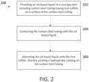
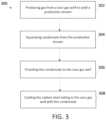
- FIG. 3is a flowchart showing operations in process 300 for mitigating surface scale formation and corrosion in a sour gas well having carbon steel tubing.
- gasis produced from the sour gas well to yield a production stream.
- the condensateis separated from the production stream.
- the condensateis provided to the sour gas well.
- the carbon steel tubingis coated with the condensate.
- providing the condensate to the sour gas wellincludes injecting the condensate between a casing of the sour gas well and the carbon steel tubing.
- the carbon steel tubingmay have iron sulfide in the form of a film or layer on a surface of the carbon steel tubing, such that coating the carbon steel tubing with the condensate comprises adsorbing the condensate onto the iron sulfide.
- Coating the carbon steel tubing with the condensateyields a hydrophobic coating on the carbon steel tubing.
- the hydrophobic coatingprevents or inhibits formation of hydrogen sulfide on the carbon steel tubing and inhibits corrosion of the carbon steel tubing.
- the hydrophobic coatingalso prevents direct contact of water in the carbon steel tubing with the carbon steel tubing.
- Condensate that does not form a coating on the carbon steel tubingmay be removed from the sour gas well and recycled.
- fluidrefers to gases, liquids, gels, slurries with a high solids content, and critical and supercritical materials.
- a subterranean formationrefers to any material under the surface of the earth, including under the surface of the bottom of the ocean.
- a subterranean formationcan be any section of a wellbore and any section of a subterranean petroleum- or water-producing formation or region in fluid contact with the wellbore.
- a subterranean formationcan be any below-ground region that can produce liquid or gaseous petroleum materials, water, or any section below-ground in fluid contact therewith.
- a subterranean formationcan be at least one of an area desired to be fractured, a fracture, or an area surrounding a fracture, and a flow pathway or an area surrounding a flow pathway, where a fracture or a flow pathway can be optionally fluidly connected to a subterranean petroleum- or water-producing region, directly or through one or more fractures or flow pathways.
Landscapes
- Engineering & Computer Science (AREA)
- Life Sciences & Earth Sciences (AREA)
- Geology (AREA)
- Mining & Mineral Resources (AREA)
- Chemical & Material Sciences (AREA)
- General Life Sciences & Earth Sciences (AREA)
- Physics & Mathematics (AREA)
- Environmental & Geological Engineering (AREA)
- Fluid Mechanics (AREA)
- Geochemistry & Mineralogy (AREA)
- Mechanical Engineering (AREA)
- Materials Engineering (AREA)
- Organic Chemistry (AREA)
- General Engineering & Computer Science (AREA)
- Metallurgy (AREA)
- General Chemical & Material Sciences (AREA)
- Inorganic Chemistry (AREA)
- Chemical Kinetics & Catalysis (AREA)
- Preventing Corrosion Or Incrustation Of Metals (AREA)
- Production Of Liquid Hydrocarbon Mixture For Refining Petroleum (AREA)
Description
- This patent claims priority to
U.S. Patent Application No. 62/476,163 filed on March 24, 2017 - This document relates to methods for mitigating corrosion of carbon steel tubing and surface scaling deposition on carbon steel tubing in oilfield applications, particularly in sour gas wells.
- Carbon steel tubing has been widely used as well completion material in sour gas wells in oilfield applications. Despite the cost effectiveness of this tubing, however, the failure of carbon steel tubing due to corrosion and surface scaling deposition downhole are two persistent issues in sour gas wells. This failure can lead to leaking, restriction of downhole surveillance and intervention, significant losses of gas production, and costly damage. While continuous injection of chemicals such as corrosion and scale inhibitors has been used to reduce corrosion and scaling in carbon steel tubing, chemical treatment is not always effective in sour gas wells given the elevated temperatures and high concentration of hydrogen sulfide. In addition, formation damage may result if the injected chemicals flow into the formation.
US4416333 describes a process of providing corrosion protection in offshore gas wells containing acid gases such as H2S or CO2 by continuously circulating a manufactured carrier oil containing a corrosion inhibitor. The method can include mixing the carrier oil with a condensate from the well or a nearby well that produces high boiling, organic compounds. The method can include determining whether, and to what extent, portions of such a carrier oil can be replaced by portions of such a condensate.US4988389 describes a method of producing fluids from subterranean reservoirs that contain hydrogen sulfide, elemental sulfur, or hydrogen polysulfides. The method includes using a jet pump, chemical injections, and downhole electrical heaters to prevent the deposition of elemental sulfur by raising the pressure, temperature, and sulfur solvency of fluids being produced in these wells.US5158693 describes reacting quartenized derivatives of oligoquinoline with refractory metal oxy salts to generate oligoquinolinium metal oxide salts. The oligoquinolinium metal oxide salts inhibit corrosion of iron based alloy articles in sulfur containing media.WO2015/042488 describes a method of inhibiting fouling caused by contaminants on a metallic tubular, flow conduit or vessel in an underground reservoir. The method includes applying a treatment agent that includes a hydrophobic tail and an anchor onto the surface of the metallic tubular, flow conduit or vessel. The anchor attaches the treatment agent onto the surface of the metallic tubular, flow conduit or vessel.- In a first general aspect, mitigating corrosion and surface scale formation in a sour gas well includes providing an oil-based liquid to a sour gas well having carbon steel tubing with iron sulfide on a surface of the carbon steel tubing, contacting the carbon steel tubing with the oil-based liquid, and adsorbing a first portion of the oil-based liquid onto the iron sulfide. Adsorbing the first portion of the oil-based liquid onto the iron sulfide yields a hydrophobic coating on the carbon steel tubing.
- Implementations of the first general aspect may include one or more of the following features.
- The iron sulfide is typically in direct contact with the surface of the carbon steel tubing. The oil-based liquid may include at least one of diesel fuel, kerosene, black oil, or condensate. The hydrophobic coating prevents or inhibits formation of hydrogen sulfide on the carbon steel tubing, prevents or inhibits corrosion of the carbon steel tubing, or both. The hydrophobic coating typically prevents or inhibits direct contact of the water with the carbon steel tubing.
- Some implementations of the first general aspect include producing gas from the sour gas well to yield a production stream and separating the oil-based liquid from the production stream before providing the oil-based liquid to the sour gas well. In one embodiment, separating the oil-based liquid from the production stream includes separating condensate from the production stream.
- Providing the oil-based liquid to the sour gas well may include injecting the oil-based liquid between a casing of the sour gas well and the carbon steel tubing.
- Some implementations of the first general aspect include removing a second portion of the oil-based liquid from the sour gas well, reintroducing the second portion of the oil-based liquid to the sour gas well, or both. Certain implementations of the first general aspect include producing gas from the sour gas well to yield a production stream comprising water, with the hydrophobic coating on the carbon steel tubing preventing or inhibiting direct contact of the water with the carbon steel tubing.
- In a second general aspect, mitigating surface scale formation and corrosion in a sour gas well includes producing gas from the sour gas well having carbon steel tubing to yield a production stream, separating condensate from the production stream, providing the condensate to the sour gas well, and coating the carbon steel tubing with a first portion of the condensate.
- Implementations of the second general aspect may include one or more of the following features.
- Providing the condensate to the sour gas well may include injecting the condensate between a casing of the sour gas well and the carbon steel tubing. Coating the carbon steel tubing with the first portion of the condensate typically yields a hydrophobic coating on the carbon steel tubing. The hydrophobic coating prevents or inhibits formation of hydrogen sulfide on the carbon steel tubing, prevents or inhibits corrosion of the carbon steel tubing, or both. The hydrophobic coating typically prevents or inhibits direct contact of the water with the carbon steel tubing.
- In some embodiments, the carbon steel tubing has iron sulfide on a surface of the carbon steel tubing, and coating the carbon steel tubing with the first portion of the condensate includes adsorbing the first portion of the condensate onto the iron sulfide.
- Some implementations of the second general aspect include removing a second portion of the condensate from the sour gas well, reintroducing the second portion of the condensate to the sour gas well, or both.
- Embodiments described herein advantageously inhibit or prevent tubing corrosion and formation of surface scale in sour gas wells. In addition, formation damage via chemical treatment is avoided, and other environmental concerns are mitigated when the injected condensate or oil-based liquids are recycled and reused. Moreover, operation costs are reduced by reducing the corrosivity of carbon steel and reducing the frequency of treatment for scale removal, and capital expenditures are reduced by increasing the durability of the carbon steel.
FIG. 1 depicts an exemplary system for providing an oil-based liquid to a sour gas well.FIG. 2 is a flowchart showing operations in a first exemplary process for mitigating surface scale formation and corrosion in a sour gas well.FIG. 3 is a flowchart showing operations in a second exemplary process for mitigating surface scale formation and corrosion in a sour gas well.- Reference will now be made in detail to certain embodiments of the disclosed subject matter. While the disclosed subject matter will be described in conjunction with the enumerated claims, it will be understood that the exemplified subject matter is not intended to limit the claims to the disclosed subject matter.
- Corrosion and surface scale formation in a sour gas well can be mitigated by reducing the contact of water with carbon steel tubing in the sour gas well. The surface scale typically includes iron sulfide. In some examples, the iron sulfide is in the form of pyrrhotite, triolite, mackinawite, pyrite, marcasite, or greigite. "Sour gas well" refers to a well that produces natural gas or any other gas containing a significant amount of hydrogen sulfide. In one example, natural gas is considered to be sour if the gas contains greater than 5.7 mg of hydrogen sulfide per cubic meter of natural gas, or greater than 4 ppm by volume under standard temperature and pressure. In another example, natural gas is considered to be sour if the gas contains greater than 24 ppm by volume or 100 ppm by volume of hydrogen sulfide. In yet another example, a few parts per million of iron sulfide by weight, such as 5 ppm, promotes iron sulfide deposition.
- Reducing the contact of water with carbon steel tubing in a sour gas well can be achieved by coating the carbon steel tubing with a hydrophobic material, thereby establishing a barrier that prevents or inhibits contact of the carbon steel tubing with water produced from the sour gas well. The hydrophobic material may be on oil-based liquid, such as diesel fuel, kerosene, or black oil. In some embodiments, the oil-based liquid is condensate produced from the sour gas well and injected back into the well. Coating the carbon steel tubing with an oil-based liquid is achievedin situ by contacting the carbon steel tubing with the oil-based liquid, such that the oil-based liquid adsorbs onto iron sulfide on the surface of the carbon steel tubing. The iron sulfide may be in the form of a continuous layer or film on the carbon steel tubing, such that the adsorbed oil-based liquid forms a continuous film or layer on the carbon steel tubing. In some embodiments, the iron sulfide is in the form of a continuous layer or film directly on the carbon steel tubing. The continuous layer of the oil-based liquid forms a barrier between the carbon steel tubing and water flowing through the tubing. Thus, rather than removing iron sulfide on the carbon steel tubing, the iron sulfide promotes adherence of the oil-based liquid to the carbon steel tubing.
- Using an oil-based liquid to mitigate corrosion and surface scale formation in sour gas wells reduces the risk of formation damage compared to chemical descaling treatments, such as injection of hydrochloric acid. Using an oil-based liquid to mitigate corrosion and surface scale formation in sour gas wells also extends the lifetime of the carbon steel tubing by avoiding the introduction of corrosive chemicals and reducing the need for chemical descaling treatments of the carbon steel tubing. In addition, because the oil-based liquid can be recycled and reused, environmental concerns regarding the flow of corrosive chemicals into the formation are avoided.
FIG. 1 depictsexemplary system 100 for providing an oil-based liquid to a sour gas well insubterranean formation 102. Oil-based liquid fromsource 104 is pumped viapump 106 throughline 108 towellhead 110, and enterscarbon steel tubing 112.Carbon steel tubing 112 is typically production steel tubing. As indicated by the arrows, oil-based liquid that does not adhere to iron sulfide on an interior surface of carbon steel tubing may circulate back upwellbore 114 through the annular path between the wellbore andcarbon steel tubing 112. This recycled oil-based liquid may be reintroduced intocarbon steel tubing 112.FIG. 2 is a flowchart showing operations inprocess 200 for mitigating surface scale formation and corrosion in a sour gas well. In 202, an oil-based liquid is provided to a sour gas well. The sour gas well includes carbon steel tubing, and the carbon steel tubing has iron sulfide on a surface of the carbon steel tubing. In one example, the iron sulfide is on an interior surface of the carbon steel tubing. The iron sulfide may be in the form of a film or a layer on the carbon steel tubing. The film or layer of iron sulfide may be in direct contact with the carbon steel tubing. In one embodiment, the iron sulfide forms a continuous film or layer on the carbon steel tubing. In 204, the carbon steel tubing is contacted with the oil-based liquid. In 206, a portion of the oil-based liquid is adsorbed onto the iron sulfide, thereby yielding a hydrophobic coating on the carbon steel tubing.- In some embodiments, the oil-based liquid includes at least one of diesel fuel, kerosene, black oil, or condensate. "Condensate" generally refers to a liquid condensed from a gas stream that includes butane, pentane, and heavier hydrocarbon fractions. In some embodiments, gas is produced from the sour gas well to yield a production stream, and the oil-based liquid is separated from the production stream. The oil-based liquid separated from the production stream may then be provided to the sour gas well. In one embodiment, condensate separated from the production stream may be provided to the sour gas well.
- In some embodiments, providing the oil-based liquid to the sour gas well comprises injecting the oil-based liquid between a casing of the sour gas well and the carbon steel tubing. In some embodiments, oil-based liquid provided to the sour gas well that did not adhere to the carbon steel tubing is recycled and reintroduced back into the sour gas well.
- In some embodiments, gas is produced from the sour gas well to yield a production stream that includes water, and the hydrophobic coating on the carbon steel tubing prevents direct contact of the water with the carbon steel tubing. The hydrophobic coating prevents formation of hydrogen sulfide on the carbon steel tubing and inhibits corrosion of the carbon steel tubing.
FIG. 3 is a flowchart showing operations inprocess 300 for mitigating surface scale formation and corrosion in a sour gas well having carbon steel tubing. In 302, gas is produced from the sour gas well to yield a production stream. In 304, the condensate is separated from the production stream. In 306, the condensate is provided to the sour gas well. In 308, the carbon steel tubing is coated with the condensate.- In some embodiments, providing the condensate to the sour gas well includes injecting the condensate between a casing of the sour gas well and the carbon steel tubing. The carbon steel tubing may have iron sulfide in the form of a film or layer on a surface of the carbon steel tubing, such that coating the carbon steel tubing with the condensate comprises adsorbing the condensate onto the iron sulfide.
- Coating the carbon steel tubing with the condensate yields a hydrophobic coating on the carbon steel tubing. The hydrophobic coating prevents or inhibits formation of hydrogen sulfide on the carbon steel tubing and inhibits corrosion of the carbon steel tubing. The hydrophobic coating also prevents direct contact of water in the carbon steel tubing with the carbon steel tubing.
- Condensate that does not form a coating on the carbon steel tubing may be removed from the sour gas well and recycled.
- In this document, the terms "a," "an," or "the" are used to include one or more than one unless the context clearly dictates otherwise. The term "or" is used to refer to a nonexclusive "or" unless otherwise indicated. The statement "at least one of A and B" has the same meaning as "A, B, or A and B." In addition, it is to be understood that the phraseology or terminology employed in this disclosure, and not otherwise defined, is for the purpose of description only and not of limitation. Any use of section headings is intended to aid reading of the document and is not to be interpreted as limiting; information that is relevant to a section heading may occur within or outside of that particular section.
- Values expressed in a range format should be interpreted in a flexible manner to include not only the numerical values explicitly recited as the limits of the range, but also to include all the individual numerical values or sub-ranges encompassed within that range as if each numerical value and sub-range is explicitly recited. For example, a range of "about 0.1% to about 5%" or "about 0.1% to 5%" should be interpreted to include not just about 0.1% to about 5%, but also the individual values (for example, 1%, 2%, 3%, and 4%) and the sub-ranges (for example, 0.1% to 0.5%, 1.1% to 2.2%, 3.3% to 4.4%) within the indicated range. The statement "about X to Y" has the same meaning as "about X to about Y," unless indicated otherwise. Likewise, the statement "about X, Y, or about Z" has the same meaning as "about X, about Y, or about Z," unless indicated otherwise. The term "about" can allow for a degree of variability in a value or range, for example, within 10%, within 5%, or within 1% of a stated value or of a stated limit of a range.
- The term "fluid" refers to gases, liquids, gels, slurries with a high solids content, and critical and supercritical materials.
- The term "subterranean formation" refers to any material under the surface of the earth, including under the surface of the bottom of the ocean. For example, a subterranean formation can be any section of a wellbore and any section of a subterranean petroleum- or water-producing formation or region in fluid contact with the wellbore. In some examples, a subterranean formation can be any below-ground region that can produce liquid or gaseous petroleum materials, water, or any section below-ground in fluid contact therewith. For example, a subterranean formation can be at least one of an area desired to be fractured, a fracture, or an area surrounding a fracture, and a flow pathway or an area surrounding a flow pathway, where a fracture or a flow pathway can be optionally fluidly connected to a subterranean petroleum- or water-producing region, directly or through one or more fractures or flow pathways.
- It is to be understood that while embodiments have been described in conjunction with the detailed description thereof, the foregoing description is intended to illustrate and not limit the scope of the invention, which is defined by the scope of the appended claims.
Claims (15)
- A method of mitigating corrosion and surface scale formation in a sour gas well, the method comprising:providing an oil-based liquid to a sour gas well comprising carbon steel tubing (112), wherein the carbon steel tubing comprises iron sulfide on a surface of the carbon steel tubing;contacting the carbon steel tubing with the oil-based liquid; andadsorbing a first portion of the oil-based liquid onto the iron sulfide, thereby yielding a hydrophobic coating on the carbon steel tubing.
- The method of claim 1, wherein providing an oil-based liquid to a sour gas well comprising steel tubing comprises providing an oil-based liquid to a well that produces natural gas that comprises greater than 4 ppm by volume of hydrogen sulfide under standard temperature and pressure.
- The method of claim 1, wherein adsorbing a first portion of the oil-based liquid onto the iron sulfide comprises adsorbing a first portion of the oil-based liquid onto the iron sulfide, wherein the iron sulfide comprises iron sulfide in the form of pyrrhotite, tiriolite, mackinawite, pyrite, marcasite, or greigite.
- The method of claim 1, wherein providing the oil-based liquid comprises providing at least one of diesel fuel, kerosene, or black oil.
- The method of any one of the above claims, wherein adsorbing a first portion of the oil-based liquid onto the iron sulfide comprises adsorbing a first portion of the oil-based liquid to iron sulfide that is in direct contact with the surface of the carbon steel tubing.
- The method of any one of the above claims, further comprising:producing gas from the sour gas well to yield a production stream; andseparating the oil-based liquid from the production stream before providing the oil-based liquid to the sour gas well.
- The method of claim 6, wherein providing the oil-based liquid to the sour gas well comprises providing an oil-based liquid that comprises condensate.
- The method of claim 7, further comprising adsorbing the condensate onto the iron sulfide.
- The method of claim 8, further comprising:removing unadsorbed condensate;recycling the unadsorbed condensate by reintroducing the recycled condensate to into the carbon steel tubing.
- The method of any one of the above claims, wherein providing the oil-based liquid to the sour gas well comprises injecting the oil-based liquid between a casing of the sour gas well and the carbon steel tubing.
- The method of any one of claims 1-7 or claim 10, when not depending on claims 8 or 9, further comprising removing a second portion of the oil-based liquid from the sour gas well.
- The method of claim 11, further comprising reintroducing the second portion of the oil-based liquid to the sour gas well.
- The method of any one of the above claims, further comprising producing gas from the sour gas well to yield a production stream comprising water, and wherein the hydrophobic coating on the carbon steel tubing prevents direct contact of the water with the carbon steel tubing.
- The method of any one of the above claims, wherein adsorbing a first portion of the oil-based liquid onto the iron sulfide, thereby yielding the hydrophobic coating inhibits or prevents formation of hydrogen sulfide on the carbon steel tubing.
- The method of any one of the above claims, wherein adsorbing a first portion of the oil-based liquid onto the iron sulfide, thereby yielding the hydrophobic coating inhibits or prevents corrosion of the carbon steel tubing.
Applications Claiming Priority (2)
| Application Number | Priority Date | Filing Date | Title |
|---|---|---|---|
| US201762476163P | 2017-03-24 | 2017-03-24 | |
| PCT/US2018/023983WO2018175862A1 (en) | 2017-03-24 | 2018-03-23 | Mitigating corrosion of carbon steel tubing and surface scaling deposition in oilfield applications |
Publications (2)
| Publication Number | Publication Date |
|---|---|
| EP3601722A1 EP3601722A1 (en) | 2020-02-05 |
| EP3601722B1true EP3601722B1 (en) | 2023-03-01 |
Family
ID=61913660
Family Applications (1)
| Application Number | Title | Priority Date | Filing Date |
|---|---|---|---|
| EP18716835.6AActiveEP3601722B1 (en) | 2017-03-24 | 2018-03-23 | Mitigating corrosion of carbon steel tubing and surface scaling deposition in oilfield applications |
Country Status (7)
| Country | Link |
|---|---|
| US (1) | US10822926B2 (en) |
| EP (1) | EP3601722B1 (en) |
| JP (1) | JP2020514558A (en) |
| CN (1) | CN110475941B (en) |
| AU (1) | AU2018237325A1 (en) |
| CA (1) | CA3057581A1 (en) |
| WO (1) | WO2018175862A1 (en) |
Families Citing this family (3)
| Publication number | Priority date | Publication date | Assignee | Title |
|---|---|---|---|---|
| WO2023019047A1 (en)* | 2021-08-09 | 2023-02-16 | ExxonMobil Technology and Engineering Company | Methods for in-situ application of a coating agent to production tubing using a plunger lift system |
| CN114062243B (en)* | 2021-11-15 | 2024-04-05 | 厦门大学 | Design method of long-acting liquid anti-corrosion layer of multiphase conveying pipeline |
| GB202501701D0 (en)* | 2022-09-08 | 2025-03-19 | Halliburton Energy Services Inc | Preventing or removing contaminants in wellbore fluid using an acoustic actuator |
Family Cites Families (38)
| Publication number | Priority date | Publication date | Assignee | Title |
|---|---|---|---|---|
| US2357559A (en) | 1942-08-24 | 1944-09-05 | Odessa Chemical And Equipment | Method of sweetening sour gas and preventing corrosion of oil producing wells |
| US2818383A (en) | 1956-12-04 | 1957-12-31 | Sun Oil Co | Inhibiting corrosion by oil well fluids |
| US2844497A (en) | 1956-12-07 | 1958-07-22 | Devex Corp | Method of applying sulfide coating on wires for drawing and composition therefor |
| US3462239A (en) | 1967-01-25 | 1969-08-19 | Shell Oil Co | Method of preventing hydrogen sulfide corrosion and embrittlement |
| US3629104A (en) | 1967-06-29 | 1971-12-21 | Texaco Inc | Water soluble corrosion inhibitors for well fluids |
| US3959170A (en) | 1971-11-22 | 1976-05-25 | Union Carbide Corporation | Corrosion inhibitors for alkanolamine gas treating system |
| US4057108A (en) | 1976-11-19 | 1977-11-08 | Shell Oil Company | Completing wells in deep reservoirs containing fluids that are hot and corrosive |
| US4100100A (en) | 1977-03-28 | 1978-07-11 | The Dow Chemical Company | Cobalt-containing inhibitor for sour gas conditioning solutions |
| US4100099A (en) | 1977-03-28 | 1978-07-11 | The Dow Chemical Company | Quaternary salt-polyamine inhibitor for sour gas conditioning solutions |
| US4372873A (en) | 1981-03-16 | 1983-02-08 | Texaco Inc. | Vanadium-amine corrosion inhibitor system for sour gas conditioning solutions |
| US4351673A (en) | 1981-05-22 | 1982-09-28 | Halliburton Company | Method for removing iron sulfide scale from metal surfaces |
| US4416333A (en)* | 1982-04-20 | 1983-11-22 | Shell Oil Company | Corrosion inhibiting process for a remotely located deep corrosive gas well |
| CA1187064A (en) | 1982-11-30 | 1985-05-14 | Edward C. Nieh | Vanadium-cobalt corrosion inhibitor system for sour gas conditioning solutions |
| CA1254505A (en) | 1987-10-02 | 1989-05-23 | Ion I. Adamache | Exploitation method for reservoirs containing hydrogen sulphide |
| US5158693A (en)* | 1991-08-29 | 1992-10-27 | Exxon Research And Engineering Co. | Oligoquinolinium metal oxide salts as sulfur corrosion inhibitors |
| US5188179A (en)* | 1991-12-23 | 1993-02-23 | Gay Richard J | Dynamic polysulfide corrosion inhibitor method and system for oil field piping |
| EP0662504A1 (en) | 1994-01-10 | 1995-07-12 | Nalco Chemical Company | Corrosion inhibition and iron sulfide dispersing in refineries using the reaction product of a hydrocarbyl succinic anhydride and an amine |
| AU3102395A (en)* | 1995-04-17 | 1996-11-07 | Bio-Technical Resources Lp | Method for inhibiting microbially influenced corrosion |
| DE19628893A1 (en)* | 1996-07-17 | 1998-01-22 | Basf Ag | Use of 1-amidoalkylimidazoles as corrosion inhibitors in the petrochemical industry and process for their preparation |
| US6131659A (en)* | 1998-07-15 | 2000-10-17 | Saudi Arabian Oil Company | Downhole well corrosion monitoring apparatus and method |
| GB0017675D0 (en) | 2000-07-20 | 2000-09-06 | Rhodia Cons Spec Ltd | Treatment of iron sulphide deposits |
| AU2002337645B2 (en) | 2001-08-15 | 2007-06-21 | Mamre, Llc | Method and composition to decrease iron sulfide deposits in pipe lines |
| WO2004031536A1 (en)* | 2002-10-07 | 2004-04-15 | Mol Hungarian Oil And Gas Co. | Method for the treatment and prevention of asphaltene-paraffin-vax precipitates in oil-wells, wellheads and pipelines by the use of biocolloid suspensions |
| GB0321276D0 (en) | 2003-09-11 | 2003-10-08 | Rhodia Consumer Specialities L | Treatment of iron sulphide deposits |
| US20060029808A1 (en) | 2004-08-06 | 2006-02-09 | Lei Zhai | Superhydrophobic coatings |
| US7455106B2 (en) | 2005-09-07 | 2008-11-25 | Schlumberger Technology Corporation | Polymer protective coated polymeric components for oilfield applications |
| CN100494490C (en)* | 2006-12-18 | 2009-06-03 | 李天忠 | A technical process to solve the corrosion of pipe drilling tools and pumps by hydrogen sulfide in oil and gas exploitation |
| US20080236842A1 (en) | 2007-03-27 | 2008-10-02 | Schlumberger Technology Corporation | Downhole oilfield apparatus comprising a diamond-like carbon coating and methods of use |
| US8282266B2 (en)* | 2007-06-27 | 2012-10-09 | H R D Corporation | System and process for inhibitor injection |
| US7855171B2 (en) | 2008-10-16 | 2010-12-21 | Trahan David O | Method and composition to remove iron and iron sulfide compounds from pipeline networks |
| WO2012087352A2 (en) | 2010-12-20 | 2012-06-28 | The Regents Of The University Of California | Superhydrophobic and superoleophobic nanosurfaces |
| US20120217012A1 (en)* | 2011-02-24 | 2012-08-30 | John Gregory Darby | Method of introducing treatment agents into a well or flow conduit |
| EP2650314A1 (en) | 2012-04-13 | 2013-10-16 | Clariant International Ltd. | Process for inhibition of sulphide scales |
| US20130284518A1 (en)* | 2012-04-27 | 2013-10-31 | 3M Innovative Properties Company | Method of using multi-component fibers as lost-circulation material |
| US20140345871A1 (en)* | 2013-05-24 | 2014-11-27 | Halliburton Energy Services, Inc. | Henna Corrosion Inhibitor for Acid in a Well |
| WO2015034516A1 (en)* | 2013-09-06 | 2015-03-12 | Halliburton Energy Services, Inc. | Method and device for downhole corrosion and erosion monitoring |
| NZ751779A (en)* | 2013-09-20 | 2020-08-28 | Baker Hughes Inc | Method of inhibiting fouling on a metallic surface using a surface modifying treatment agent |
| CN106194126B (en)* | 2016-09-19 | 2019-01-01 | 中国石油化工股份有限公司 | The integral method gone into operation for high sour gas well debugging |
- 2018
- 2018-03-23EPEP18716835.6Apatent/EP3601722B1/enactiveActive
- 2018-03-23JPJP2019552451Apatent/JP2020514558A/ennot_activeWithdrawn
- 2018-03-23WOPCT/US2018/023983patent/WO2018175862A1/ennot_activeCeased
- 2018-03-23CACA3057581Apatent/CA3057581A1/enactivePending
- 2018-03-23USUS15/934,645patent/US10822926B2/enactiveActive
- 2018-03-23CNCN201880020725.3Apatent/CN110475941B/enactiveActive
- 2018-03-23AUAU2018237325Apatent/AU2018237325A1/ennot_activeAbandoned
Also Published As
| Publication number | Publication date |
|---|---|
| CN110475941B (en) | 2022-04-15 |
| AU2018237325A1 (en) | 2019-10-31 |
| JP2020514558A (en) | 2020-05-21 |
| US20180274339A1 (en) | 2018-09-27 |
| CN110475941A (en) | 2019-11-19 |
| WO2018175862A1 (en) | 2018-09-27 |
| CA3057581A1 (en) | 2018-09-27 |
| EP3601722A1 (en) | 2020-02-05 |
| US10822926B2 (en) | 2020-11-03 |
Similar Documents
| Publication | Publication Date | Title |
|---|---|---|
| Saji et al. | Corrosion inhibitors in the oil and gas industry | |
| Al-Janabi | An overview of corrosion in oil and gas industry: upstream, midstream, and downstream sectors | |
| EP3601722B1 (en) | Mitigating corrosion of carbon steel tubing and surface scaling deposition in oilfield applications | |
| Bonis et al. | Weight loss corrosion with H2S: using past operations for designing future facilities | |
| BR112017008482B1 (en) | METHOD TO SUPPRESS CORROSION OF STEEL SURFACES | |
| WO2015016889A1 (en) | Corrosion inhibitor intensifiers for corrosion resistant alloys | |
| US20170233638A1 (en) | Use of Hexamethylenetetramine Intensifier for High Temperature Emulsified Acid System | |
| Gregg et al. | Review of corrosion inhibitor developments and testing for offshore oil and gas production systems | |
| Tian et al. | Low dosage hydrate inhibitors (LDHI): advances and developments in flow assurance technology for offshore oil and gas productions | |
| EA034819B1 (en) | Process for removing metal naphthenate from crude hydrocarbon mixtures | |
| CA2766188C (en) | Method of transporting fluids and reducing the total acid number | |
| Nasr-El-Din | Formation damage induced by chemical treatments: case histories | |
| Onojake et al. | Review of oilfield chemicals used in oil and gas industry | |
| Sykes et al. | Optimising MEG chemistry when producing formation water | |
| Reyes-Garcia et al. | Operational Efficiency Gains in the Removal of Calcium Sulfate Scale from Electric Submersible Pumps in Offshore Wells | |
| Hatscher et al. | Acid and Scale Inhibitor Squeeze Treatments on Two Subsea Gas Condensate Wells: Design of Subsea Connection, Treatment, Wells Start-Up and Results of the Operation. | |
| Penkala et al. | Acrolein application to mitigate biogenic sulfides and remediate injection-well damage in a gas-plant water-disposal system | |
| US11313043B2 (en) | Coating carbon steel tubing with iron sulfide | |
| Kamshad et al. | Challenges of Implementing Chemical Treatment Preservation Programs on Oil Production Wells during a Prolonged Shutdown within Partitioned Zone (Kingdom of Saudi Arabia and State of Kuwait) | |
| Kuijvenhoven et al. | Bacteria and Microbiologically Induced Corrosion Control in Unconventional Gas Field | |
| Saji | Corrosion Inhibitors in the Oil and Gas Industry | |
| Jiang et al. | Plugging Mechanism and Chemical Plugging Removal Technology for Shale Gas Wells in Zhaotong Block | |
| King | Maureen produced water injection | |
| Wylde | Re-commissioning of mothballed pipelines offshore California: A success story of cleaning, pigging, monitoring and integrity management | |
| Stone et al. | Completion design for waterfloods and CO2 floods |
Legal Events
| Date | Code | Title | Description |
|---|---|---|---|
| STAA | Information on the status of an ep patent application or granted ep patent | Free format text:STATUS: UNKNOWN | |
| STAA | Information on the status of an ep patent application or granted ep patent | Free format text:STATUS: THE INTERNATIONAL PUBLICATION HAS BEEN MADE | |
| PUAI | Public reference made under article 153(3) epc to a published international application that has entered the european phase | Free format text:ORIGINAL CODE: 0009012 | |
| STAA | Information on the status of an ep patent application or granted ep patent | Free format text:STATUS: REQUEST FOR EXAMINATION WAS MADE | |
| 17P | Request for examination filed | Effective date:20191017 | |
| AK | Designated contracting states | Kind code of ref document:A1 Designated state(s):AL AT BE BG CH CY CZ DE DK EE ES FI FR GB GR HR HU IE IS IT LI LT LU LV MC MK MT NL NO PL PT RO RS SE SI SK SM TR | |
| AX | Request for extension of the european patent | Extension state:BA ME | |
| DAV | Request for validation of the european patent (deleted) | ||
| DAX | Request for extension of the european patent (deleted) | ||
| GRAP | Despatch of communication of intention to grant a patent | Free format text:ORIGINAL CODE: EPIDOSNIGR1 | |
| STAA | Information on the status of an ep patent application or granted ep patent | Free format text:STATUS: GRANT OF PATENT IS INTENDED | |
| RIC1 | Information provided on ipc code assigned before grant | Ipc:F16L 58/04 20060101ALI20221109BHEP Ipc:C23F 15/00 20060101ALI20221109BHEP Ipc:C09K 8/528 20060101ALI20221109BHEP Ipc:C09K 8/54 20060101ALI20221109BHEP Ipc:E21B 43/40 20060101ALI20221109BHEP Ipc:E21B 41/02 20060101ALI20221109BHEP Ipc:E21B 37/06 20060101AFI20221109BHEP | |
| INTG | Intention to grant announced | Effective date:20221125 | |
| GRAS | Grant fee paid | Free format text:ORIGINAL CODE: EPIDOSNIGR3 | |
| GRAA | (expected) grant | Free format text:ORIGINAL CODE: 0009210 | |
| STAA | Information on the status of an ep patent application or granted ep patent | Free format text:STATUS: THE PATENT HAS BEEN GRANTED | |
| AK | Designated contracting states | Kind code of ref document:B1 Designated state(s):AL AT BE BG CH CY CZ DE DK EE ES FI FR GB GR HR HU IE IS IT LI LT LU LV MC MK MT NL NO PL PT RO RS SE SI SK SM TR | |
| REG | Reference to a national code | Ref country code:GB Ref legal event code:FG4D | |
| REG | Reference to a national code | Ref country code:CH Ref legal event code:EP Ref country code:AT Ref legal event code:REF Ref document number:1551082 Country of ref document:AT Kind code of ref document:T Effective date:20230315 | |
| REG | Reference to a national code | Ref country code:DE Ref legal event code:R096 Ref document number:602018046647 Country of ref document:DE | |
| REG | Reference to a national code | Ref country code:IE Ref legal event code:FG4D | |
| REG | Reference to a national code | Ref country code:NO Ref legal event code:T2 Effective date:20230301 | |
| REG | Reference to a national code | Ref country code:LT Ref legal event code:MG9D | |
| REG | Reference to a national code | Ref country code:NL Ref legal event code:MP Effective date:20230301 | |
| P01 | Opt-out of the competence of the unified patent court (upc) registered | Effective date:20230528 | |
| PG25 | Lapsed in a contracting state [announced via postgrant information from national office to epo] | Ref country code:RS Free format text:LAPSE BECAUSE OF FAILURE TO SUBMIT A TRANSLATION OF THE DESCRIPTION OR TO PAY THE FEE WITHIN THE PRESCRIBED TIME-LIMIT Effective date:20230301 Ref country code:LV Free format text:LAPSE BECAUSE OF FAILURE TO SUBMIT A TRANSLATION OF THE DESCRIPTION OR TO PAY THE FEE WITHIN THE PRESCRIBED TIME-LIMIT Effective date:20230301 Ref country code:LT Free format text:LAPSE BECAUSE OF FAILURE TO SUBMIT A TRANSLATION OF THE DESCRIPTION OR TO PAY THE FEE WITHIN THE PRESCRIBED TIME-LIMIT Effective date:20230301 Ref country code:HR Free format text:LAPSE BECAUSE OF FAILURE TO SUBMIT A TRANSLATION OF THE DESCRIPTION OR TO PAY THE FEE WITHIN THE PRESCRIBED TIME-LIMIT Effective date:20230301 Ref country code:ES Free format text:LAPSE BECAUSE OF FAILURE TO SUBMIT A TRANSLATION OF THE DESCRIPTION OR TO PAY THE FEE WITHIN THE PRESCRIBED TIME-LIMIT Effective date:20230301 | |
| REG | Reference to a national code | Ref country code:AT Ref legal event code:MK05 Ref document number:1551082 Country of ref document:AT Kind code of ref document:T Effective date:20230301 | |
| PG25 | Lapsed in a contracting state [announced via postgrant information from national office to epo] | Ref country code:SE Free format text:LAPSE BECAUSE OF FAILURE TO SUBMIT A TRANSLATION OF THE DESCRIPTION OR TO PAY THE FEE WITHIN THE PRESCRIBED TIME-LIMIT Effective date:20230301 Ref country code:PL Free format text:LAPSE BECAUSE OF FAILURE TO SUBMIT A TRANSLATION OF THE DESCRIPTION OR TO PAY THE FEE WITHIN THE PRESCRIBED TIME-LIMIT Effective date:20230301 Ref country code:NL Free format text:LAPSE BECAUSE OF FAILURE TO SUBMIT A TRANSLATION OF THE DESCRIPTION OR TO PAY THE FEE WITHIN THE PRESCRIBED TIME-LIMIT Effective date:20230301 Ref country code:FI Free format text:LAPSE BECAUSE OF FAILURE TO SUBMIT A TRANSLATION OF THE DESCRIPTION OR TO PAY THE FEE WITHIN THE PRESCRIBED TIME-LIMIT Effective date:20230301 | |
| REG | Reference to a national code | Ref country code:DE Ref legal event code:R119 Ref document number:602018046647 Country of ref document:DE | |
| PG25 | Lapsed in a contracting state [announced via postgrant information from national office to epo] | Ref country code:SM Free format text:LAPSE BECAUSE OF FAILURE TO SUBMIT A TRANSLATION OF THE DESCRIPTION OR TO PAY THE FEE WITHIN THE PRESCRIBED TIME-LIMIT Effective date:20230301 Ref country code:RO Free format text:LAPSE BECAUSE OF FAILURE TO SUBMIT A TRANSLATION OF THE DESCRIPTION OR TO PAY THE FEE WITHIN THE PRESCRIBED TIME-LIMIT Effective date:20230301 Ref country code:PT Free format text:LAPSE BECAUSE OF FAILURE TO SUBMIT A TRANSLATION OF THE DESCRIPTION OR TO PAY THE FEE WITHIN THE PRESCRIBED TIME-LIMIT Effective date:20230703 Ref country code:EE Free format text:LAPSE BECAUSE OF FAILURE TO SUBMIT A TRANSLATION OF THE DESCRIPTION OR TO PAY THE FEE WITHIN THE PRESCRIBED TIME-LIMIT Effective date:20230301 Ref country code:CZ Free format text:LAPSE BECAUSE OF FAILURE TO SUBMIT A TRANSLATION OF THE DESCRIPTION OR TO PAY THE FEE WITHIN THE PRESCRIBED TIME-LIMIT Effective date:20230301 Ref country code:AT Free format text:LAPSE BECAUSE OF FAILURE TO SUBMIT A TRANSLATION OF THE DESCRIPTION OR TO PAY THE FEE WITHIN THE PRESCRIBED TIME-LIMIT Effective date:20230301 | |
| REG | Reference to a national code | Ref country code:CH Ref legal event code:PL | |
| PG25 | Lapsed in a contracting state [announced via postgrant information from national office to epo] | Ref country code:SK Free format text:LAPSE BECAUSE OF FAILURE TO SUBMIT A TRANSLATION OF THE DESCRIPTION OR TO PAY THE FEE WITHIN THE PRESCRIBED TIME-LIMIT Effective date:20230301 Ref country code:IS Free format text:LAPSE BECAUSE OF FAILURE TO SUBMIT A TRANSLATION OF THE DESCRIPTION OR TO PAY THE FEE WITHIN THE PRESCRIBED TIME-LIMIT Effective date:20230701 | |
| REG | Reference to a national code | Ref country code:BE Ref legal event code:MM Effective date:20230331 | |
| PG25 | Lapsed in a contracting state [announced via postgrant information from national office to epo] | Ref country code:LU Free format text:LAPSE BECAUSE OF NON-PAYMENT OF DUE FEES Effective date:20230323 | |
| PLBE | No opposition filed within time limit | Free format text:ORIGINAL CODE: 0009261 | |
| STAA | Information on the status of an ep patent application or granted ep patent | Free format text:STATUS: NO OPPOSITION FILED WITHIN TIME LIMIT | |
| PG25 | Lapsed in a contracting state [announced via postgrant information from national office to epo] | Ref country code:MC Free format text:LAPSE BECAUSE OF FAILURE TO SUBMIT A TRANSLATION OF THE DESCRIPTION OR TO PAY THE FEE WITHIN THE PRESCRIBED TIME-LIMIT Effective date:20230301 | |
| REG | Reference to a national code | Ref country code:IE Ref legal event code:MM4A | |
| PG25 | Lapsed in a contracting state [announced via postgrant information from national office to epo] | Ref country code:SI Free format text:LAPSE BECAUSE OF FAILURE TO SUBMIT A TRANSLATION OF THE DESCRIPTION OR TO PAY THE FEE WITHIN THE PRESCRIBED TIME-LIMIT Effective date:20230301 Ref country code:MC Free format text:LAPSE BECAUSE OF FAILURE TO SUBMIT A TRANSLATION OF THE DESCRIPTION OR TO PAY THE FEE WITHIN THE PRESCRIBED TIME-LIMIT Effective date:20230301 Ref country code:LI Free format text:LAPSE BECAUSE OF NON-PAYMENT OF DUE FEES Effective date:20230331 Ref country code:IE Free format text:LAPSE BECAUSE OF NON-PAYMENT OF DUE FEES Effective date:20230323 Ref country code:FR Free format text:LAPSE BECAUSE OF NON-PAYMENT OF DUE FEES Effective date:20230501 Ref country code:DK Free format text:LAPSE BECAUSE OF FAILURE TO SUBMIT A TRANSLATION OF THE DESCRIPTION OR TO PAY THE FEE WITHIN THE PRESCRIBED TIME-LIMIT Effective date:20230301 Ref country code:DE Free format text:LAPSE BECAUSE OF NON-PAYMENT OF DUE FEES Effective date:20231003 Ref country code:CH Free format text:LAPSE BECAUSE OF NON-PAYMENT OF DUE FEES Effective date:20230331 | |
| 26N | No opposition filed | Effective date:20231204 | |
| PG25 | Lapsed in a contracting state [announced via postgrant information from national office to epo] | Ref country code:BE Free format text:LAPSE BECAUSE OF NON-PAYMENT OF DUE FEES Effective date:20230331 | |
| PG25 | Lapsed in a contracting state [announced via postgrant information from national office to epo] | Ref country code:IT Free format text:LAPSE BECAUSE OF FAILURE TO SUBMIT A TRANSLATION OF THE DESCRIPTION OR TO PAY THE FEE WITHIN THE PRESCRIBED TIME-LIMIT Effective date:20230301 | |
| PG25 | Lapsed in a contracting state [announced via postgrant information from national office to epo] | Ref country code:BG Free format text:LAPSE BECAUSE OF FAILURE TO SUBMIT A TRANSLATION OF THE DESCRIPTION OR TO PAY THE FEE WITHIN THE PRESCRIBED TIME-LIMIT Effective date:20230301 | |
| PG25 | Lapsed in a contracting state [announced via postgrant information from national office to epo] | Ref country code:BG Free format text:LAPSE BECAUSE OF FAILURE TO SUBMIT A TRANSLATION OF THE DESCRIPTION OR TO PAY THE FEE WITHIN THE PRESCRIBED TIME-LIMIT Effective date:20230301 | |
| PGFP | Annual fee paid to national office [announced via postgrant information from national office to epo] | Ref country code:NO Payment date:20250325 Year of fee payment:8 | |
| PGFP | Annual fee paid to national office [announced via postgrant information from national office to epo] | Ref country code:GB Payment date:20250320 Year of fee payment:8 | |
| PG25 | Lapsed in a contracting state [announced via postgrant information from national office to epo] | Ref country code:CY Free format text:LAPSE BECAUSE OF FAILURE TO SUBMIT A TRANSLATION OF THE DESCRIPTION OR TO PAY THE FEE WITHIN THE PRESCRIBED TIME-LIMIT; INVALID AB INITIO Effective date:20180323 | |
| PG25 | Lapsed in a contracting state [announced via postgrant information from national office to epo] | Ref country code:HU Free format text:LAPSE BECAUSE OF FAILURE TO SUBMIT A TRANSLATION OF THE DESCRIPTION OR TO PAY THE FEE WITHIN THE PRESCRIBED TIME-LIMIT; INVALID AB INITIO Effective date:20180323 | |
| PG25 | Lapsed in a contracting state [announced via postgrant information from national office to epo] | Ref country code:GR Free format text:LAPSE BECAUSE OF FAILURE TO SUBMIT A TRANSLATION OF THE DESCRIPTION OR TO PAY THE FEE WITHIN THE PRESCRIBED TIME-LIMIT; INVALID AB INITIO Effective date:20180323 |