EP3600089B1 - Apparatus for removal of intracranial hemorrhage - Google Patents
Apparatus for removal of intracranial hemorrhageDownload PDFInfo
- Publication number
- EP3600089B1 EP3600089B1EP18770942.3AEP18770942AEP3600089B1EP 3600089 B1EP3600089 B1EP 3600089B1EP 18770942 AEP18770942 AEP 18770942AEP 3600089 B1EP3600089 B1EP 3600089B1
- Authority
- EP
- European Patent Office
- Prior art keywords
- blade
- lesion
- probe shaft
- lumen
- tubular probe
- Prior art date
- Legal status (The legal status is an assumption and is not a legal conclusion. Google has not performed a legal analysis and makes no representation as to the accuracy of the status listed.)
- Active
Links
Images


Classifications
- A—HUMAN NECESSITIES
- A61—MEDICAL OR VETERINARY SCIENCE; HYGIENE
- A61B—DIAGNOSIS; SURGERY; IDENTIFICATION
- A61B17/00—Surgical instruments, devices or methods
- A61B17/32—Surgical cutting instruments
- A61B17/320016—Endoscopic cutting instruments, e.g. arthroscopes, resectoscopes
- A61B17/32002—Endoscopic cutting instruments, e.g. arthroscopes, resectoscopes with continuously rotating, oscillating or reciprocating cutting instruments
- A—HUMAN NECESSITIES
- A61—MEDICAL OR VETERINARY SCIENCE; HYGIENE
- A61B—DIAGNOSIS; SURGERY; IDENTIFICATION
- A61B17/00—Surgical instruments, devices or methods
- A61B17/00234—Surgical instruments, devices or methods for minimally invasive surgery
- A—HUMAN NECESSITIES
- A61—MEDICAL OR VETERINARY SCIENCE; HYGIENE
- A61B—DIAGNOSIS; SURGERY; IDENTIFICATION
- A61B17/00—Surgical instruments, devices or methods
- A61B17/16—Instruments for performing osteoclasis; Drills or chisels for bones; Trepans
- A61B17/1695—Trepans or craniotomes, i.e. specially adapted for drilling thin bones such as the skull
- A—HUMAN NECESSITIES
- A61—MEDICAL OR VETERINARY SCIENCE; HYGIENE
- A61B—DIAGNOSIS; SURGERY; IDENTIFICATION
- A61B17/00—Surgical instruments, devices or methods
- A61B17/22—Implements for squeezing-off ulcers or the like on inner organs of the body; Implements for scraping-out cavities of body organs, e.g. bones; for invasive removal or destruction of calculus using mechanical vibrations; for removing obstructions in blood vessels, not otherwise provided for
- A61B17/22031—Gripping instruments, e.g. forceps, for removing or smashing calculi
- A—HUMAN NECESSITIES
- A61—MEDICAL OR VETERINARY SCIENCE; HYGIENE
- A61B—DIAGNOSIS; SURGERY; IDENTIFICATION
- A61B17/00—Surgical instruments, devices or methods
- A61B17/32—Surgical cutting instruments
- A61B17/3205—Excision instruments
- A61B17/3207—Atherectomy devices working by cutting or abrading; Similar devices specially adapted for non-vascular obstructions
- A61B17/320758—Atherectomy devices working by cutting or abrading; Similar devices specially adapted for non-vascular obstructions with a rotating cutting instrument, e.g. motor driven
- A—HUMAN NECESSITIES
- A61—MEDICAL OR VETERINARY SCIENCE; HYGIENE
- A61B—DIAGNOSIS; SURGERY; IDENTIFICATION
- A61B17/00—Surgical instruments, devices or methods
- A61B17/22—Implements for squeezing-off ulcers or the like on inner organs of the body; Implements for scraping-out cavities of body organs, e.g. bones; for invasive removal or destruction of calculus using mechanical vibrations; for removing obstructions in blood vessels, not otherwise provided for
- A61B17/22004—Implements for squeezing-off ulcers or the like on inner organs of the body; Implements for scraping-out cavities of body organs, e.g. bones; for invasive removal or destruction of calculus using mechanical vibrations; for removing obstructions in blood vessels, not otherwise provided for using mechanical vibrations, e.g. ultrasonic shock waves
- A61B17/22012—Implements for squeezing-off ulcers or the like on inner organs of the body; Implements for scraping-out cavities of body organs, e.g. bones; for invasive removal or destruction of calculus using mechanical vibrations; for removing obstructions in blood vessels, not otherwise provided for using mechanical vibrations, e.g. ultrasonic shock waves in direct contact with, or very close to, the obstruction or concrement
- A61B17/2202—Implements for squeezing-off ulcers or the like on inner organs of the body; Implements for scraping-out cavities of body organs, e.g. bones; for invasive removal or destruction of calculus using mechanical vibrations; for removing obstructions in blood vessels, not otherwise provided for using mechanical vibrations, e.g. ultrasonic shock waves in direct contact with, or very close to, the obstruction or concrement the ultrasound transducer being inside patient's body at the distal end of the catheter
- A—HUMAN NECESSITIES
- A61—MEDICAL OR VETERINARY SCIENCE; HYGIENE
- A61B—DIAGNOSIS; SURGERY; IDENTIFICATION
- A61B17/00—Surgical instruments, devices or methods
- A61B2017/00367—Details of actuation of instruments, e.g. relations between pushing buttons, or the like, and activation of the tool, working tip, or the like
- A61B2017/00398—Details of actuation of instruments, e.g. relations between pushing buttons, or the like, and activation of the tool, working tip, or the like using powered actuators, e.g. stepper motors, solenoids
- A—HUMAN NECESSITIES
- A61—MEDICAL OR VETERINARY SCIENCE; HYGIENE
- A61B—DIAGNOSIS; SURGERY; IDENTIFICATION
- A61B17/00—Surgical instruments, devices or methods
- A61B2017/00681—Aspects not otherwise provided for
- A61B2017/00685—Archimedes screw
- A—HUMAN NECESSITIES
- A61—MEDICAL OR VETERINARY SCIENCE; HYGIENE
- A61B—DIAGNOSIS; SURGERY; IDENTIFICATION
- A61B17/00—Surgical instruments, devices or methods
- A61B17/22—Implements for squeezing-off ulcers or the like on inner organs of the body; Implements for scraping-out cavities of body organs, e.g. bones; for invasive removal or destruction of calculus using mechanical vibrations; for removing obstructions in blood vessels, not otherwise provided for
- A61B2017/22079—Implements for squeezing-off ulcers or the like on inner organs of the body; Implements for scraping-out cavities of body organs, e.g. bones; for invasive removal or destruction of calculus using mechanical vibrations; for removing obstructions in blood vessels, not otherwise provided for with suction of debris
- A—HUMAN NECESSITIES
- A61—MEDICAL OR VETERINARY SCIENCE; HYGIENE
- A61B—DIAGNOSIS; SURGERY; IDENTIFICATION
- A61B17/00—Surgical instruments, devices or methods
- A61B17/32—Surgical cutting instruments
- A61B17/320016—Endoscopic cutting instruments, e.g. arthroscopes, resectoscopes
- A61B17/32002—Endoscopic cutting instruments, e.g. arthroscopes, resectoscopes with continuously rotating, oscillating or reciprocating cutting instruments
- A61B2017/320024—Morcellators, e.g. having a hollow cutting tube with an annular cutter for morcellating and removing tissue
- A—HUMAN NECESSITIES
- A61—MEDICAL OR VETERINARY SCIENCE; HYGIENE
- A61B—DIAGNOSIS; SURGERY; IDENTIFICATION
- A61B17/00—Surgical instruments, devices or methods
- A61B17/32—Surgical cutting instruments
- A61B17/320016—Endoscopic cutting instruments, e.g. arthroscopes, resectoscopes
- A61B17/32002—Endoscopic cutting instruments, e.g. arthroscopes, resectoscopes with continuously rotating, oscillating or reciprocating cutting instruments
- A61B2017/320028—Endoscopic cutting instruments, e.g. arthroscopes, resectoscopes with continuously rotating, oscillating or reciprocating cutting instruments with reciprocating movements
- A—HUMAN NECESSITIES
- A61—MEDICAL OR VETERINARY SCIENCE; HYGIENE
- A61B—DIAGNOSIS; SURGERY; IDENTIFICATION
- A61B17/00—Surgical instruments, devices or methods
- A61B17/32—Surgical cutting instruments
- A61B17/320016—Endoscopic cutting instruments, e.g. arthroscopes, resectoscopes
- A61B17/32002—Endoscopic cutting instruments, e.g. arthroscopes, resectoscopes with continuously rotating, oscillating or reciprocating cutting instruments
- A61B2017/320032—Details of the rotating or oscillating shaft, e.g. using a flexible shaft
- A—HUMAN NECESSITIES
- A61—MEDICAL OR VETERINARY SCIENCE; HYGIENE
- A61B—DIAGNOSIS; SURGERY; IDENTIFICATION
- A61B17/00—Surgical instruments, devices or methods
- A61B17/32—Surgical cutting instruments
- A61B17/320068—Surgical cutting instruments using mechanical vibrations, e.g. ultrasonic
- A61B2017/32007—Surgical cutting instruments using mechanical vibrations, e.g. ultrasonic with suction or vacuum means
- A—HUMAN NECESSITIES
- A61—MEDICAL OR VETERINARY SCIENCE; HYGIENE
- A61B—DIAGNOSIS; SURGERY; IDENTIFICATION
- A61B2217/00—General characteristics of surgical instruments
- A61B2217/002—Auxiliary appliance
- A61B2217/005—Auxiliary appliance with suction drainage system
Definitions
- the present inventionrelates generally to the field of medical devices. More specifically, the invention described herein relates to devices for the minimally invasive removal of intracranial hemorrhages.
- Strokeis a significant cause of disability and death, and a growing problem for global healthcare. More than 700,000 people in the United States alone suffer a stroke each year, and of these, more than 150,000 people die. Of those who survive a stroke, roughly 90% will suffer long term impairment of movement, sensation, memory, or reasoning, ranging from mild to severe. The total cost to the U.S. healthcare system is estimated to be over $50 billion per year.
- Strokemay be caused by a blockage in a cerebral artery resulting from a thromboembolism (referred to as an "ischemic stroke"), or by a rupture of a cerebral artery (referred to as a “hemorrhagic stroke”).
- Hemorrhagic strokeresults in bleeding within the skull, limiting blood supply to brain cells, and placing harmful pressure on delicate brain tissue. Blood loss, swelling, herniation of brain tissue, and pooling of blood that results in formation of clot mass inside the skull all rapidly destroy brain tissue.
- Hemorrhagic strokeis a life-threatening medical emergency with limited treatment options.
- the Apollo TM Systemtreats clots caused by hemorrhagic stroke by the administration of high frequency, low intensity ultrasound, referred to as trans-cranial Doppler (TCD) ultrasound, using a wand introduced through a burr hole in the skull.
- TCDtrans-cranial Doppler
- the ultrasound therapydisrupts clots to immediately reduce the deleterious pressure exerted on brain tissue.
- the therapyhas been shown to safely treat hemorrhagic stroke.
- Other cerebral disordersmay also benefit from the administration of high-frequency, low intensity ultrasound, or TCD. Examples include dementia, head trauma, intracranial hematoma, Alzheimer's, and other abnormalities.
- TCD ultrasoundfor treating dense clot resulting from hemorrhagic stroke, or other diseased tissue
- the transmission of energy from an ultrasound generator to the tip of a wandresults in a diminution of energy at the tip of the wand. Consequently, the amount of energy available at the tip of the wand may not be sufficient for treatment of conditions such as fibroids, tumors, cysts, or other relatively dense tissue.
- the present inventionprovides improved apparatus for the minimally invasive disruption and removal of tissue lesions and clot from tissue in patients. While the apparatus will be particularly useful for the removal of a clot resulting from intracranial hemorrhage in a patient's brain, it will also be useful for removal of lesions from other parts of the anatomy. The apparatus of the present invention will also be useful for performing other procedures, such as removing excess fluids, tumor biopsy, tumor evacuation, and other endoscopic procedures.
- the present disclosurecomprises methods for removing a lesion from a patient's brain.
- the methodcomprises advancing a distal end of a tubular probe shaft through the patient's skull to a site of the lesion.
- An element at the distal end of the probe shaftis actuated to cut or abrade the lesion which results in the production of lesion fragments.
- the lesion fragmentsare aspirated from the site through the tubular probe shaft.
- the methodscomprise actuating a blade to cut or abrade the lesion, typically by rotating or rotationally oscillating the blade.
- the bladeis typically a planar blade having a central axis which is aligned with a longitudinal access of the tubular probe shaft.
- the bladehas a "bident” or “cornu” configuration.
- such a “bident” or “cornu” configurationhas a leading distal cutting edge which is generally transverse to the axis and a base end opposite to the distal cutting edge.
- a pair of lateral sidesmay generally be tapered in a direction from distal cutting edge toward the base end.
- the base endwill be configured to be fixedly or removably attached to a distal end of a helical or other drive shaft (as described below).
- the leading cutting edgewill have cutting points at its lateral extremities and usually have a concave or otherwise recessed region between the lateral extremities.
- the exemplary blades of the apparatus according to the present inventionare attached to a helical drive wire which is disposed in a lumen of the tubular probe shaft.
- the helical or other drive shaftis then rotated or rotationally oscillated to in turn rotate or rotationally oscillate the blade in order to cut or abrade the lesion.
- the helical drive wire of the apparatus according to the present inventionis driven by a motor which is attached to a proximal end of the drive shaft.
- the motoris located in a handle which is attached to a proximal end of the tubular probe shaft.
- the tubular probe shafthas at least one lumen running its entire length, and a vacuum may be drawn on a proximal end of the lumen in the tubular probe shaft in order to evacuate clot or other lesion fragments.
- the vacuumis drawn through an aspiration tube which is attached to a proximal end of the tubular drive shaft and in fluid communication with the lumen therein.
- the proximal end of the aspiration tubein turn, is connected to a suitable vacuum source, and the vacuum source will typically be connected to a collection canister or other receptacle for the lesion fragments.
- the helical drive shaftcan act as an "Archimedes screw” when it rotates in order to help "pump” fluid and entrained lesion fragments proximally through the tubular probe shaft lumen and inhibit clogging.
- the helical wiremaintains contact with the hypotube along its length.
- the helixmaintains contact with the hypotube for its entire length, and rotation of the helical wire within the hypotube causes continual abrading or wiping of the wire by the hypotube prevents accumulation of clot on the wire. Clot that is knocked off the wire as a result of contact with the hypotube flows towards the collection chamber. The continual process helps prevent clogging, and helps ensure continuous vacuum.
- the present inventioncomprises apparatus for removing clot or other lesion from a patient's brain.
- the apparatuscomprises a tubular probe shaft having a lumen and a distal end configured to be advanced through a hole formed in a patient's skull.
- the distal end of the tubular probe shaftmay be advanced to a site of the lesion, and an element at the distal end of the tubular probe shaft is configured to cut or abrade the clot to produce lesion fragments.
- a proximal end of the tubular shaft lumenis configured to be connected to a vacuum source to aspirate the lesion fragments from the site through the tubular probe shaft.
- a helical drive shaftis disposed in the lumen of the tubular probe shaft, and the element comprises a blade configured to be rotated or rotationally oscillated by the helical drive shaft.
- the bladeis disposed at a distal opening of the lumen, where the blade is usually a planar blade aligned with a longitudinal access of the tubular probe shaft. In specific configurations, the blade will have a bident or cornu configuration, as previously discussed.
- the apparatus of the present inventionwill usually include a handle at the proximal end of the tubular probe shaft.
- a motor for driving the helical or other drive shaftis typically disposed within the handle and coupled to a proximal end of the drive shaft.
- the motoris configured to rotate and/or rotationally oscillate the drive shaft to in turn rotate and/or rotationally oscillate the blade.
- the motor and the drive shaftare axially aligned with the longitudinal access of the probe shaft.
- the aspiration tubein contrast, will be offset from or diverge from the axis of the probe shaft so that the motor and probe shaft will not interfere with each other in the handle.
- the motoris typically battery-driven and the battery for driving the motor is typically in the handle.
- the aspiration tubewill be connected to a proximal end of the tubular probe shaft so that the vacuum drawn through the aspiration tube will draw lesion fragments into the aspiration tube and eventually to the vacuum source and disposal canister.
- the helical drive shaftin turn, ca act as an Archimedes' screw in helping move the fragments proximally through the probe shaft lumen, as previously discussed.
- the aspiration controlcan be provided on the handle.
- the aspiration controlcomprises either a slot or a generally circular aperture, or both, in the aspiration structure configured to bleed vacuum from the aspiration tube.
- a slottypically referred to as a Fukushima slot for aspiration control
- a switch for turning on and off and/or controlling the speed of the blade motorcan be provided adjacent to or as part of the vacuum control slot. In this way, the user needs only one hand to both control the motor and to control the aspiration vacuum.
- the apparatus of the present inventionmay be used to perform any one or more of a variety of medical procedures, including removal of intracranial hematoma and other lesions, removal of excess fluid, tumor biopsy, tumor evacuation, or other endoscopic procedure.
- the apparatustypically provide a combination of mechanical disruption, usually by cutting and/or abrading the clot or other lesion, and aspiration to remove fragments created by the mechanical disruption.
- the proceduresmost likely will be performed utilizing fluoroscopic or other imaging techniques, but such imaging techniques are not necessarily part of the disclosed method.
- a patient's skull 10is illustrated. Skull 10 is partly broken away to show an interior 12 which is afflicted with a lesion, mass, or region of clot 14.
- burr hole 16was formed on patient's skull 10, providing access from the exterior of skull 10 to the interior 12. Burr hole 16 will permit access for treatment of mass 14.
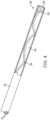
- Fig. 2illustrates a lesion disruption apparatus 20 constructed in accordance with the principles of the present invention.
- the lesion disruption apparatus 20comprises a tubular probe shaft 22 attached at its proximal end to a handle 24.
- An aspiration tube 26extends outwardly from a proximal end of the handle 24 and is attached to an external console 18 which typically includes a vacuum pump or other source 28 which aspirates and directs lesion fragments from the lesion disruption apparatus 20 to a collection canister 30.
- the lesion disruption apparatus 20can be connected and disconnected from the vacuum source 28 in the external console 18, typically through a connector which is part of the aspiration tube 26 (not shown herein).
- the lesion disruption apparatus 20will be fully self-contained other than requiring connection to the vacuum source. That is, power for driving the abrasion/cutter will be provided by a battery within the handle, and controls for the motor to drive the cutter and for adjusting the amount of aspiration vacuum are also provided on the handle, typically by control element(s) 32
- a proximal end 23 of the probe shaft 22is typically connected to a distal end 27 of the aspiration tube 26 at a location within the handle 24.
- a helical drive shaft 36is disposed within a lumen 34 of the tubular probe shaft 22 and extends in a proximal direction through a distal portion of the aspiration lumen 34.
- a proximal end of the drive shaft 36extends out of the aspiration tube 26 through a bushing or a bearing 48 which passes through a wall of the aspiration tube.
- the distal end of the drive shaftis thus exterior to the flow lumen of aspiration tube and is connected to a drive motor 38 which in turn is connected to a battery 40.
- the motor 38drives a spindle 42 which is coupled to the distal end of the drive shaft 36 by a ferrule 44 and polymeric sleeve 46.
- the ferrule 44is crimped or otherwise connected to the distal end of the drive shaft 36 in order to provide a larger effective diameter.
- the larger diameterwill generally match that of the spindle 42, and the spindle and proximal end of the drive shaft may then be coupled using the polymeric sleeve 46 which bridges the ends of both the spindle 42 and the ferrule 44.
- a spacewill be left between the adjacent ends of the drive shaft and the spindle to provide for electrical isolation.
- the hypotube and aspiration tubingare typically separated by an aspiration chamber assembly (not illustrate in Fig. 3 ). This assembly acts as a junction that connects the aspiration button, aspiration tubing, and hypotube. In addition it has a very tight pass through that all the motor wire to rotate, but still creates an air tight seal.
- Vacuum control within the aspiration tube 26can be provided by an open slot 52 ( Fig. 3A ) formed in a branch 50 of the aspiration tube.
- the branch 50will extend out of the handle, generally at the control element region 32 as illustrated in Fig. 2 .
- the usermay then manually cover the slot in order to adjust the amount of vacuum leakage through the slot. That is, when the slot is fully uncovered, the vacuum will be minimal as unimpeded air can enter through the slot 52. Conversely, by manually covering all or a portion of the slot, the degree of the vacuum can be controlled from minimum to maximum.
- a push button or other switchmay be used to control aspiration.
- Fig. 3Billustrates an exemplary alternative embodiment of a handle 60 with one side removed having a drive motor 62 and battery 64 housed therein.
- Battery 64provides power to drive motor 62.
- Drive motor 62drives a spindle 65 which is coupled to the distal end of a shaft, or motor wire (not visible) and functions to rotate the shaft or motor wire.
- the shaft, or motor wirewhich is not visible in Fig. 3B , is housed within hypotube 66.
- motor wireWhen actuated by a user, motor wire (not visible) rotates within hypotube 66, and functions in a fashion similar to the embodiments described above in order to disrupt clot or other diseased tissue, and prevent clogging of the aspiration tubing.
- the helical drive shaft 36extends through a central lumen 54 of the tubular prove shaft 22 and carries a planar blade 56 at its distal end.
- the planar blade 56is exposed in an open distal end 60 of the tube 22 so that the blade can engage and fragment a lesion as the drive shaft 36 is rotate or rotationally oscillated by motor 36.
- target tissuesuch as a region of clot within a patient's brain, can engage the blade against the tissue in order to fragment the lesion, clot, or other anatomy present in the tissue.
- the region of intracranial clot 14can be removed from a patient's brain by advancing the distal end of the tubular probe shaft 22 through the burr hole 16 in the patient's skull.
- the depth of the distal tip of the shaftcan be observed, typically via indicators on the shaft or other introducer device, and the position of the tip further observed, for example, via endoscopic camera visualization" and when in the proper position, the blade can be actuated and the vacuum modulated in order to fragment and remove clot or other lesion fragments in order to treat the patient.
- Presence of the helical drive shaft 36 in the lumen 54can help transport the clot fragments through the shaft and to the aspirations tube 26 from where they can be removed by the vacuum source 28 ( Fig. 1 ).
Landscapes
- Health & Medical Sciences (AREA)
- Surgery (AREA)
- Life Sciences & Earth Sciences (AREA)
- Medical Informatics (AREA)
- Animal Behavior & Ethology (AREA)
- Engineering & Computer Science (AREA)
- Biomedical Technology (AREA)
- Heart & Thoracic Surgery (AREA)
- Veterinary Medicine (AREA)
- Molecular Biology (AREA)
- Nuclear Medicine, Radiotherapy & Molecular Imaging (AREA)
- General Health & Medical Sciences (AREA)
- Public Health (AREA)
- Orthopedic Medicine & Surgery (AREA)
- Vascular Medicine (AREA)
- Neurosurgery (AREA)
- Dentistry (AREA)
- Oral & Maxillofacial Surgery (AREA)
- Surgical Instruments (AREA)
Description
- This application claims the benefit of
U.S. Provisional No. 62/473,779 (Attorney Docket No. 41507-723.101), filed March 20, 2017 - 1.Field of the Invention. The present invention relates generally to the field of medical devices. More specifically, the invention described herein relates to devices for the minimally invasive removal of intracranial hemorrhages.
- Stroke is a significant cause of disability and death, and a growing problem for global healthcare. More than 700,000 people in the United States alone suffer a stroke each year, and of these, more than 150,000 people die. Of those who survive a stroke, roughly 90% will suffer long term impairment of movement, sensation, memory, or reasoning, ranging from mild to severe. The total cost to the U.S. healthcare system is estimated to be over $50 billion per year.
- Stroke may be caused by a blockage in a cerebral artery resulting from a thromboembolism (referred to as an "ischemic stroke"), or by a rupture of a cerebral artery (referred to as a "hemorrhagic stroke"). Hemorrhagic stroke results in bleeding within the skull, limiting blood supply to brain cells, and placing harmful pressure on delicate brain tissue. Blood loss, swelling, herniation of brain tissue, and pooling of blood that results in formation of clot mass inside the skull all rapidly destroy brain tissue. Hemorrhagic stroke is a life-threatening medical emergency with limited treatment options.
- Of particular interest to the present invention, the Apollo™ System treats clots caused by hemorrhagic stroke by the administration of high frequency, low intensity ultrasound, referred to as trans-cranial Doppler (TCD) ultrasound, using a wand introduced through a burr hole in the skull. The ultrasound therapy disrupts clots to immediately reduce the deleterious pressure exerted on brain tissue. Combined with visualization and aspiration, the therapy has been shown to safely treat hemorrhagic stroke. Other cerebral disorders may also benefit from the administration of high-frequency, low intensity ultrasound, or TCD. Examples include dementia, head trauma, intracranial hematoma, Alzheimer's, and other abnormalities.
- Although very effective, the use of TCD ultrasound for treating dense clot resulting from hemorrhagic stroke, or other diseased tissue, suffers from certain shortcomings. For example, the transmission of energy from an ultrasound generator to the tip of a wand results in a diminution of energy at the tip of the wand. Consequently, the amount of energy available at the tip of the wand may not be sufficient for treatment of conditions such as fibroids, tumors, cysts, or other relatively dense tissue.
- Therefore, it would be desirable to provide improved apparatus for the minimally invasive disruption and removal of clot in patients who have suffered hemorrhagic stroke. It would be particularly desirable if such improved apparatus were also useful for treating dementia, head trauma, intracranial hematoma, Alzheimer's, and other abnormalities. At least some of these objectives will be met by the inventions described herein below.
- 2.Description of the Background Art. The Apollo™ System is at in the Apollo System Instructions for Use.
US 8,366,620 andUS 2012/0330196 describe the use of TCD for removing hemorrhagic clot. Mechanical thrombectomy and atherectomy devices are described inUS9,055,964 US9,017,294 US8,764,779 ;US8,246,752 ;US8,1 14,106 ;US7,172,610 ; andUS9,282,992 US 2009/124975 A1 discloses an apparatus with suction means for surgically treating a brain tumor of a patient.US 2014/246840 A1 discloses a surgical apparatus with a distal blade and an helical shaft that urges the dislocated tissues through the cannula. - The present invention provides improved apparatus for the minimally invasive disruption and removal of tissue lesions and clot from tissue in patients. While the apparatus will be particularly useful for the removal of a clot resulting from intracranial hemorrhage in a patient's brain, it will also be useful for removal of lesions from other parts of the anatomy. The apparatus of the present invention will also be useful for performing other procedures, such as removing excess fluids, tumor biopsy, tumor evacuation, and other endoscopic procedures.
- The apparatus of the invention is defined in claim 1. Preferred embodiments are defined in the dependent claims. The methods disclosed are used to aid the understanding of the claimed invention.
- In a first aspect, the present disclosure comprises methods for removing a lesion from a patient's brain. The method comprises advancing a distal end of a tubular probe shaft through the patient's skull to a site of the lesion. An element at the distal end of the probe shaft is actuated to cut or abrade the lesion which results in the production of lesion fragments. The lesion fragments are aspirated from the site through the tubular probe shaft.
- In exemplary embodiments, the methods comprise actuating a blade to cut or abrade the lesion, typically by rotating or rotationally oscillating the blade. The blade is typically a planar blade having a central axis which is aligned with a longitudinal access of the tubular probe shaft. In specific embodiments, the blade has a "bident" or "cornu" configuration. In general, such a "bident" or "cornu" configuration has a leading distal cutting edge which is generally transverse to the axis and a base end opposite to the distal cutting edge. A pair of lateral sides may generally be tapered in a direction from distal cutting edge toward the base end. The base end will be configured to be fixedly or removably attached to a distal end of a helical or other drive shaft (as described below). The leading cutting edge will have cutting points at its lateral extremities and usually have a concave or otherwise recessed region between the lateral extremities.
- The exemplary blades of the apparatus according to the present invention are attached to a helical drive wire which is disposed in a lumen of the tubular probe shaft. The helical or other drive shaft is then rotated or rotationally oscillated to in turn rotate or rotationally oscillate the blade in order to cut or abrade the lesion.
- In other specific aspects, the helical drive wire of the apparatus according to the present invention is driven by a motor which is attached to a proximal end of the drive shaft. In most instances, the motor is located in a handle which is attached to a proximal end of the tubular probe shaft. The tubular probe shaft has at least one lumen running its entire length, and a vacuum may be drawn on a proximal end of the lumen in the tubular probe shaft in order to evacuate clot or other lesion fragments. The vacuum is drawn through an aspiration tube which is attached to a proximal end of the tubular drive shaft and in fluid communication with the lumen therein. The proximal end of the aspiration tube in turn, is connected to a suitable vacuum source, and the vacuum source will typically be connected to a collection canister or other receptacle for the lesion fragments. The helical drive shaft can act as an "Archimedes screw" when it rotates in order to help "pump" fluid and entrained lesion fragments proximally through the tubular probe shaft lumen and inhibit clogging. The helical wire maintains contact with the hypotube along its length. The helix maintains contact with the hypotube for its entire length, and rotation of the helical wire within the hypotube causes continual abrading or wiping of the wire by the hypotube prevents accumulation of clot on the wire. Clot that is knocked off the wire as a result of contact with the hypotube flows towards the collection chamber. The continual process helps prevent clogging, and helps ensure continuous vacuum.
- The present invention comprises apparatus for removing clot or other lesion from a patient's brain. The apparatus comprises a tubular probe shaft having a lumen and a distal end configured to be advanced through a hole formed in a patient's skull. The distal end of the tubular probe shaft may be advanced to a site of the lesion, and an element at the distal end of the tubular probe shaft is configured to cut or abrade the clot to produce lesion fragments. A proximal end of the tubular shaft lumen is configured to be connected to a vacuum source to aspirate the lesion fragments from the site through the tubular probe shaft.
- A helical drive shaft is disposed in the lumen of the tubular probe shaft, and the element comprises a blade configured to be rotated or rotationally oscillated by the helical drive shaft. The blade is disposed at a distal opening of the lumen, where the blade is usually a planar blade aligned with a longitudinal access of the tubular probe shaft. In specific configurations, the blade will have a bident or cornu configuration, as previously discussed.
- The apparatus of the present invention will usually include a handle at the proximal end of the tubular probe shaft. A motor for driving the helical or other drive shaft is typically disposed within the handle and coupled to a proximal end of the drive shaft. The motor is configured to rotate and/or rotationally oscillate the drive shaft to in turn rotate and/or rotationally oscillate the blade.
- In specific embodiments, the motor and the drive shaft are axially aligned with the longitudinal access of the probe shaft. The aspiration tube, in contrast, will be offset from or diverge from the axis of the probe shaft so that the motor and probe shaft will not interfere with each other in the handle. The motor is typically battery-driven and the battery for driving the motor is typically in the handle. The aspiration tube will be connected to a proximal end of the tubular probe shaft so that the vacuum drawn through the aspiration tube will draw lesion fragments into the aspiration tube and eventually to the vacuum source and disposal canister. The helical drive shaft, in turn, ca act as an Archimedes' screw in helping move the fragments proximally through the probe shaft lumen, as previously discussed.
- Aspiration control can be provided on the handle. In the exemplary embodiments, the aspiration control comprises either a slot or a generally circular aperture, or both, in the aspiration structure configured to bleed vacuum from the aspiration tube. As an example of one such embodiment, a slot, typically referred to as a Fukushima slot for aspiration control, can be manually covered by a user's thumb or finger to control the rate at which vacuum is bled from the aspiration system. By fully covering the slot, a maximum vacuum is maintained. Conversely, by fully uncovering the slot, minimum vacuum is maintained. Optionally, a switch for turning on and off and/or controlling the speed of the blade motor can be provided adjacent to or as part of the vacuum control slot. In this way, the user needs only one hand to both control the motor and to control the aspiration vacuum.
Fig. 1 is a schematic illustration of a patient's skull showing a region of clot or other lesion to be treated and a burr hole site useful for performing the methods disclosed.Fig. 2 illustrates a mechanical blade lesion disruption apparatus constructed in accordance with the principles of the present invention.Fig. 3 illustrates a motor drive assembly connected to a drive shaft that passes through an aspiration tube and enters a tubular probe shaft.Fig. 3A is detailed view of a slot for controlling vacuum in the aspiration tube of Fig. taken alongline 3A-3A inFig. 3 .Fig. 3B illustrates the internal components of an alternative embodiment of a motor drive assembly.Fig. 4 is a detailed view of a tubular probe shaft with portions broken away to show a helical drive shaft which carries a mechanical blade.Fig. 5 illustrates use of the apparatus ofFig. 2 in removing a clot lesion from a patient's brain in accordance with the principles of the present invention.- Some embodiments of the invention are described below. For clarity, not all features of each actual implementation are described in this specification. In the development of an actual device, some modifications may be made that result in an embodiment that still falls within the scope of the invention defined by the claims.
- The apparatus of the present invention may be used to perform any one or more of a variety of medical procedures, including removal of intracranial hematoma and other lesions, removal of excess fluid, tumor biopsy, tumor evacuation, or other endoscopic procedure. The apparatus typically provide a combination of mechanical disruption, usually by cutting and/or abrading the clot or other lesion, and aspiration to remove fragments created by the mechanical disruption. The procedures most likely will be performed utilizing fluoroscopic or other imaging techniques, but such imaging techniques are not necessarily part of the disclosed method.
- In
Fig. 1 , a patient'sskull 10 is illustrated.Skull 10 is partly broken away to show an interior 12 which is afflicted with a lesion, mass, or region ofclot 14. In a previous step in the procedure,burr hole 16 was formed on patient'sskull 10, providing access from the exterior ofskull 10 to the interior 12.Burr hole 16 will permit access for treatment ofmass 14. Fig. 2 illustrates alesion disruption apparatus 20 constructed in accordance with the principles of the present invention. Thelesion disruption apparatus 20 comprises atubular probe shaft 22 attached at its proximal end to ahandle 24. Anaspiration tube 26 extends outwardly from a proximal end of thehandle 24 and is attached to anexternal console 18 which typically includes a vacuum pump orother source 28 which aspirates and directs lesion fragments from thelesion disruption apparatus 20 to acollection canister 30. Thelesion disruption apparatus 20 can be connected and disconnected from thevacuum source 28 in theexternal console 18, typically through a connector which is part of the aspiration tube 26 (not shown herein). In the illustrated embodiments, thelesion disruption apparatus 20 will be fully self-contained other than requiring connection to the vacuum source. That is, power for driving the abrasion/cutter will be provided by a battery within the handle, and controls for the motor to drive the cutter and for adjusting the amount of aspiration vacuum are also provided on the handle, typically by control element(s) 32.- Referring now to
Figs. 3 and 3A , aproximal end 23 of theprobe shaft 22 is typically connected to adistal end 27 of theaspiration tube 26 at a location within thehandle 24. Ahelical drive shaft 36 is disposed within alumen 34 of thetubular probe shaft 22 and extends in a proximal direction through a distal portion of theaspiration lumen 34. A proximal end of thedrive shaft 36 extends out of theaspiration tube 26 through a bushing or abearing 48 which passes through a wall of the aspiration tube. The distal end of the drive shaft is thus exterior to the flow lumen of aspiration tube and is connected to adrive motor 38 which in turn is connected to abattery 40. In particular, themotor 38 drives aspindle 42 which is coupled to the distal end of thedrive shaft 36 by aferrule 44 andpolymeric sleeve 46. Theferrule 44 is crimped or otherwise connected to the distal end of thedrive shaft 36 in order to provide a larger effective diameter. The larger diameter will generally match that of thespindle 42, and the spindle and proximal end of the drive shaft may then be coupled using thepolymeric sleeve 46 which bridges the ends of both thespindle 42 and theferrule 44. Usually, a space will be left between the adjacent ends of the drive shaft and the spindle to provide for electrical isolation. The hypotube and aspiration tubing are typically separated by an aspiration chamber assembly (not illustrate inFig. 3 ). This assembly acts as a junction that connects the aspiration button, aspiration tubing, and hypotube. In addition it has a very tight pass through that all the motor wire to rotate, but still creates an air tight seal. - Vacuum control within the
aspiration tube 26 can be provided by an open slot 52 (Fig. 3A ) formed in abranch 50 of the aspiration tube. Thebranch 50 will extend out of the handle, generally at thecontrol element region 32 as illustrated inFig. 2 . The user may then manually cover the slot in order to adjust the amount of vacuum leakage through the slot. That is, when the slot is fully uncovered, the vacuum will be minimal as unimpeded air can enter through theslot 52. Conversely, by manually covering all or a portion of the slot, the degree of the vacuum can be controlled from minimum to maximum. In the alternative, a push button or other switch may be used to control aspiration. Fig. 3B illustrates an exemplary alternative embodiment of ahandle 60 with one side removed having adrive motor 62 and battery 64 housed therein. Battery 64 provides power to drivemotor 62. Drivemotor 62 drives aspindle 65 which is coupled to the distal end of a shaft, or motor wire (not visible) and functions to rotate the shaft or motor wire. The shaft, or motor wire, which is not visible inFig. 3B , is housed within hypotube 66. When actuated by a user, motor wire (not visible) rotates within hypotube 66, and functions in a fashion similar to the embodiments described above in order to disrupt clot or other diseased tissue, and prevent clogging of the aspiration tubing.- Referring now to
Fig. 4 , thehelical drive shaft 36 extends through acentral lumen 54 of the tubular proveshaft 22 and carries aplanar blade 56 at its distal end. Theplanar blade 56, in turn, is exposed in an opendistal end 60 of thetube 22 so that the blade can engage and fragment a lesion as thedrive shaft 36 is rotate or rotationally oscillated bymotor 36. In this way, advancing thetubular probe shaft 22 into target tissue, such as a region of clot within a patient's brain, can engage the blade against the tissue in order to fragment the lesion, clot, or other anatomy present in the tissue. - As shown in
Fig. 5 , the region ofintracranial clot 14 can be removed from a patient's brain by advancing the distal end of thetubular probe shaft 22 through theburr hole 16 in the patient's skull. The depth of the distal tip of the shaft can be observed, typically via indicators on the shaft or other introducer device, and the position of the tip further observed, for example, via endoscopic camera visualization" and when in the proper position, the blade can be actuated and the vacuum modulated in order to fragment and remove clot or other lesion fragments in order to treat the patient. Presence of thehelical drive shaft 36 in thelumen 54 can help transport the clot fragments through the shaft and to theaspirations tube 26 from where they can be removed by the vacuum source 28 (Fig. 1 ). - The foregoing examples are not intended to limit the scope of the invention. All modifications within the scope of the claims are within the scope of the invention.
Claims (10)
- Apparatus for removing a lesion from a patient's brain, said apparatus comprising:a tubular probe shaft (22) having a lumen (34) and a distal end (27) configured to be advanced through a hole (16) in the patient's skull (10) to a site of the lesion;a helical wire (36) disposed in the lumen (34) and carrying a blade at its distal end, the blade being exposed at the distal end of the tubular probe shaft so that the blade can engage the lesion, wherein, upon rotation or rotational oscillation of the helical wire (36), the blade is configured to fragment the lesion and the helical wire (36) is configured to help transport lesion fragments proximally through the lumen (34); andwherein a proximal end (23) of the tubular probe shaft lumen is configured to be connected to a vacuum source (28) to aspirate the lesion fragments from the site through the tubular probe shaft (22).
- The apparatus of claim 1, wherein the blade is a planar blade (56) configured to be rotated or rotationally oscillated by the helical wire (36).
- The apparatus of claim 2, wherein the planar blade (56) has a central axis aligned with a longitudinal axis of the helical wire (36).
- The apparatus of claim 2 or 3, wherein the planar blade (56) has a bident configuration.
- The apparatus of any of claims 1 to 4, further comprising a handle (24) at a proximal end of the tubular probe shaft, wherein a motor (38) within the handle is coupled to a proximal end of the drive shaft and wherein the motor (38) is configured to rotate or rotationally oscillate the drive shaft to in turn rotate or rotationally oscillate the blade.
- The apparatus of claim 5, wherein the motor (38) and the drive shaft (36) are axially aligned with the probe shaft (22) and an aspiration tube diverges from the axis of the probe shaft (22).
- The apparatus of claim 5 or 6, further comprising a battery (64) within the handle coupled to provide current to the motor (38).
- The apparatus of any of claims 1 to 7, further comprising an aspiration tube (26) attached to a proximal end of the lumen in the tubular probe shaft (22), wherein a lumen of the aspiration tube is contiguous with the lumen in the tubular probe shaft (22).
- The apparatus of claim 8, further comprising an aspiration control on the handle (24).
- The apparatus of claim 9, wherein the aspiration control comprises a manually coverable slot (52) configured to bleed suction from the aspiration tube.
Applications Claiming Priority (2)
| Application Number | Priority Date | Filing Date | Title |
|---|---|---|---|
| US201762473779P | 2017-03-20 | 2017-03-20 | |
| PCT/US2018/023348WO2018175431A1 (en) | 2017-03-20 | 2018-03-20 | Methods and apparatus for removal of intracranial hemorrhage |
Publications (3)
| Publication Number | Publication Date |
|---|---|
| EP3600089A1 EP3600089A1 (en) | 2020-02-05 |
| EP3600089A4 EP3600089A4 (en) | 2020-12-30 |
| EP3600089B1true EP3600089B1 (en) | 2023-09-06 |
Family
ID=63521375
Family Applications (1)
| Application Number | Title | Priority Date | Filing Date |
|---|---|---|---|
| EP18770942.3AActiveEP3600089B1 (en) | 2017-03-20 | 2018-03-20 | Apparatus for removal of intracranial hemorrhage |
Country Status (7)
| Country | Link |
|---|---|
| US (2) | US10716590B2 (en) |
| EP (1) | EP3600089B1 (en) |
| JP (1) | JP2020511269A (en) |
| KR (1) | KR102687413B1 (en) |
| AU (1) | AU2018239346B2 (en) |
| CA (1) | CA3057102A1 (en) |
| WO (1) | WO2018175431A1 (en) |
Families Citing this family (10)
| Publication number | Priority date | Publication date | Assignee | Title |
|---|---|---|---|---|
| CN105228688B (en) | 2013-03-15 | 2019-02-19 | 伊瑟拉医疗公司 | Vascular treatment devices and methods |
| CN108697423A (en) | 2016-02-16 | 2018-10-23 | 伊瑟拉医疗公司 | The part flow arrangement of suction unit and anchoring |
| US10258357B1 (en) | 2017-10-16 | 2019-04-16 | Michael Bruce Horowitz | Catheter based retrieval device with proximal body having axial freedom of movement |
| US12114877B2 (en) | 2017-10-16 | 2024-10-15 | Retriever Medical, Inc. | Clot removal methods and devices with multiple independently controllable elements |
| US12201315B2 (en) | 2017-10-16 | 2025-01-21 | Retriever Medical, Inc. | Clot removal methods and devices with multiple independently controllable elements |
| USD847864S1 (en) | 2018-01-22 | 2019-05-07 | Insera Therapeutics, Inc. | Pump |
| US10531883B1 (en) | 2018-07-20 | 2020-01-14 | Syntheon 2.0, LLC | Aspiration thrombectomy system and methods for thrombus removal with aspiration catheter |
| CN110141303B (en) | 2019-06-06 | 2022-09-02 | 赛诺神畅医疗科技有限公司 | Apparatus for breaking thrombus and sucking thrombus |
| JP2024024698A (en)* | 2021-01-11 | 2024-02-26 | テルモ株式会社 | medical device |
| US12220139B2 (en) | 2022-03-20 | 2025-02-11 | Von Vascular, Inc. | System, devices and methods for removing obstructions in body lumens |
Citations (2)
| Publication number | Priority date | Publication date | Assignee | Title |
|---|---|---|---|---|
| US20040236312A1 (en)* | 2003-03-10 | 2004-11-25 | Pathway Medical Technologies, Inc. | Seal for a connector of a movable catheter system |
| US20160331645A1 (en)* | 2007-11-21 | 2016-11-17 | Actuated Medical, Inc. | Devices for Clearing Blockages in Artificial and Natural Lumens |
Family Cites Families (30)
| Publication number | Priority date | Publication date | Assignee | Title |
|---|---|---|---|---|
| US4986807A (en)* | 1989-01-23 | 1991-01-22 | Interventional Technologies, Inc. | Atherectomy cutter with radially projecting blade |
| WO1994024941A1 (en)* | 1993-04-30 | 1994-11-10 | Px Holding S.A. | Device for removing tissue by means of endoscopy |
| CA2273149A1 (en)* | 1996-12-02 | 1998-06-11 | Angiotrax, Inc. | Apparatus and methods for percutaneously performing surgery |
| US6666874B2 (en) | 1998-04-10 | 2003-12-23 | Endicor Medical, Inc. | Rotational atherectomy system with serrated cutting tip |
| US6592541B1 (en)* | 1998-07-21 | 2003-07-15 | Badrudin Kurwa | Ophthalmological surgical instrument, device and method of use |
| US8414543B2 (en) | 1999-10-22 | 2013-04-09 | Rex Medical, L.P. | Rotational thrombectomy wire with blocking device |
| US7905896B2 (en) | 2004-03-04 | 2011-03-15 | Straub Medical Ag | Catheter for aspirating, fragmenting and removing material |
| CA2506961C (en)* | 2004-05-11 | 2013-05-07 | Inrad, Inc. | Core biopsy device |
| US20060095045A1 (en)* | 2004-11-01 | 2006-05-04 | Sdgi Holdings, Inc. | Methods for explantation of intervertebral disc implants |
| US7717853B2 (en) | 2005-06-24 | 2010-05-18 | Henry Nita | Methods and apparatus for intracranial ultrasound delivery |
| US20120330196A1 (en) | 2005-06-24 | 2012-12-27 | Penumbra Inc. | Methods and Apparatus for Removing Blood Clots and Tissue from the Patient's Head |
| EP2462882B1 (en)* | 2006-10-04 | 2016-12-28 | Boston Scientific Limited | Interventional catheters |
| WO2008058160A2 (en)* | 2006-11-06 | 2008-05-15 | Aardvark Medical, Llc | Irrigation and aspiration device and method |
| US8906053B2 (en)* | 2007-11-12 | 2014-12-09 | Medtronic Xomed, Inc. | Systems and methods for surgical removal of brain tumors |
| US8246752B2 (en) | 2008-01-25 | 2012-08-21 | Clear Catheter Systems, Inc. | Methods and devices to clear obstructions from medical tubes |
| US8070765B2 (en)* | 2009-01-28 | 2011-12-06 | Medtronic Xomed, Inc. | Systems and methods for surgical removal of brain tumors |
| CN102695463B (en)* | 2009-12-11 | 2015-01-14 | 泰科保健集团有限合伙公司 | Material removal device having improved material capture efficiency and methods of use |
| US8469981B2 (en)* | 2010-02-11 | 2013-06-25 | Ethicon Endo-Surgery, Inc. | Rotatable cutting implement arrangements for ultrasonic surgical instruments |
| US8764779B2 (en) | 2010-05-13 | 2014-07-01 | Rex Medical, L.P. | Rotational thrombectomy wire |
| CA2815186C (en)* | 2010-10-28 | 2015-12-29 | Covidien Lp | Material removal device and method of use |
| US9055964B2 (en) | 2011-03-15 | 2015-06-16 | Angio Dynamics, Inc. | Device and method for removing material from a hollow anatomical structure |
| PL221914B1 (en) | 2011-10-25 | 2016-06-30 | Andrzej Sobolewski | Manually powered vehicle |
| US9603610B2 (en)* | 2013-03-15 | 2017-03-28 | DePuy Synthes Products, Inc. | Tools and methods for tissue removal |
| US10219814B2 (en)* | 2013-12-13 | 2019-03-05 | Rex Medical, L.P. | Aspiration system for thrombectomy procedures |
| EP3136998B1 (en)* | 2014-04-28 | 2019-11-27 | Boston Scientific Scimed, Inc. | Tissue resectors with cutting wires and hand-operated tissue resector systems |
| US10667836B2 (en)* | 2014-04-28 | 2020-06-02 | Boston Scientific Scimed, Inc. | Tissue resectors, hand operated tissue resecting systems, and associated methods |
| US10517632B2 (en)* | 2015-06-25 | 2019-12-31 | Covidien Lp | Tissue-removing catheter with reciprocating tissue-removing head |
| US10555834B2 (en)* | 2016-07-11 | 2020-02-11 | Novartis Ag | Vitrectomy probe with rotary cutter and associated devices, systems, and methods |
| US10105042B2 (en)* | 2016-08-17 | 2018-10-23 | Rebound Therapeutics Corporation | Cannula with proximally mounted camera |
| US20200113619A1 (en)* | 2018-10-11 | 2020-04-16 | Rebound Therapeutics Corporation | Cautery tool for intracranial surgery |
- 2018
- 2018-03-20EPEP18770942.3Apatent/EP3600089B1/enactiveActive
- 2018-03-20AUAU2018239346Apatent/AU2018239346B2/enactiveActive
- 2018-03-20KRKR1020197030602Apatent/KR102687413B1/enactiveActive
- 2018-03-20WOPCT/US2018/023348patent/WO2018175431A1/ennot_activeCeased
- 2018-03-20USUS15/926,357patent/US10716590B2/enactiveActive
- 2018-03-20CACA3057102Apatent/CA3057102A1/enactivePending
- 2018-03-20JPJP2019552106Apatent/JP2020511269A/enactivePending
- 2020
- 2020-06-30USUS16/917,413patent/US11389186B2/enactiveActive
Patent Citations (2)
| Publication number | Priority date | Publication date | Assignee | Title |
|---|---|---|---|---|
| US20040236312A1 (en)* | 2003-03-10 | 2004-11-25 | Pathway Medical Technologies, Inc. | Seal for a connector of a movable catheter system |
| US20160331645A1 (en)* | 2007-11-21 | 2016-11-17 | Actuated Medical, Inc. | Devices for Clearing Blockages in Artificial and Natural Lumens |
Also Published As
| Publication number | Publication date |
|---|---|
| WO2018175431A1 (en) | 2018-09-27 |
| US11389186B2 (en) | 2022-07-19 |
| US20180263646A1 (en) | 2018-09-20 |
| JP2020511269A (en) | 2020-04-16 |
| US20200330117A1 (en) | 2020-10-22 |
| EP3600089A4 (en) | 2020-12-30 |
| US10716590B2 (en) | 2020-07-21 |
| EP3600089A1 (en) | 2020-02-05 |
| KR20200012828A (en) | 2020-02-05 |
| KR102687413B1 (en) | 2024-07-24 |
| AU2018239346A1 (en) | 2019-10-03 |
| AU2018239346B2 (en) | 2020-11-26 |
| CA3057102A1 (en) | 2018-09-27 |
Similar Documents
| Publication | Publication Date | Title |
|---|---|---|
| EP3600089B1 (en) | Apparatus for removal of intracranial hemorrhage | |
| US12343070B2 (en) | Electrosurgical cutting instrument | |
| AU2019280219B2 (en) | Devices and methods for intrabody surgery | |
| US20230397926A1 (en) | Devices and methods for intrabody surgery | |
| US11547435B2 (en) | Cooled burr surgical instruments | |
| US8109956B2 (en) | Systems and methods for surgical removal of tissue | |
| US6066153A (en) | Device and method for resecting body tissues | |
| EP3345557B1 (en) | Combined debrider and coagulator | |
| US7232439B2 (en) | Bipolar tissue morcellator | |
| US20030055404A1 (en) | Endoscopic rotary abraders | |
| US20100312102A1 (en) | Systems, devices, and methods for accessing body tissue | |
| EP3361971B1 (en) | Surgical device | |
| EP3801312B1 (en) | Devices for intrabody surgery |
Legal Events
| Date | Code | Title | Description |
|---|---|---|---|
| STAA | Information on the status of an ep patent application or granted ep patent | Free format text:STATUS: THE INTERNATIONAL PUBLICATION HAS BEEN MADE | |
| PUAI | Public reference made under article 153(3) epc to a published international application that has entered the european phase | Free format text:ORIGINAL CODE: 0009012 | |
| STAA | Information on the status of an ep patent application or granted ep patent | Free format text:STATUS: REQUEST FOR EXAMINATION WAS MADE | |
| 17P | Request for examination filed | Effective date:20190927 | |
| AK | Designated contracting states | Kind code of ref document:A1 Designated state(s):AL AT BE BG CH CY CZ DE DK EE ES FI FR GB GR HR HU IE IS IT LI LT LU LV MC MK MT NL NO PL PT RO RS SE SI SK SM TR | |
| AX | Request for extension of the european patent | Extension state:BA ME | |
| DAV | Request for validation of the european patent (deleted) | ||
| DAX | Request for extension of the european patent (deleted) | ||
| A4 | Supplementary search report drawn up and despatched | Effective date:20201202 | |
| RIC1 | Information provided on ipc code assigned before grant | Ipc:A61B 17/32 20060101AFI20201126BHEP Ipc:A61B 17/00 20060101ALN20201126BHEP | |
| STAA | Information on the status of an ep patent application or granted ep patent | Free format text:STATUS: EXAMINATION IS IN PROGRESS | |
| 17Q | First examination report despatched | Effective date:20220516 | |
| GRAP | Despatch of communication of intention to grant a patent | Free format text:ORIGINAL CODE: EPIDOSNIGR1 | |
| STAA | Information on the status of an ep patent application or granted ep patent | Free format text:STATUS: GRANT OF PATENT IS INTENDED | |
| RIC1 | Information provided on ipc code assigned before grant | Ipc:A61B 17/00 20060101ALN20221124BHEP Ipc:A61B 17/32 20060101AFI20221124BHEP | |
| INTG | Intention to grant announced | Effective date:20221209 | |
| GRAJ | Information related to disapproval of communication of intention to grant by the applicant or resumption of examination proceedings by the epo deleted | Free format text:ORIGINAL CODE: EPIDOSDIGR1 | |
| STAA | Information on the status of an ep patent application or granted ep patent | Free format text:STATUS: EXAMINATION IS IN PROGRESS | |
| GRAP | Despatch of communication of intention to grant a patent | Free format text:ORIGINAL CODE: EPIDOSNIGR1 | |
| STAA | Information on the status of an ep patent application or granted ep patent | Free format text:STATUS: GRANT OF PATENT IS INTENDED | |
| INTC | Intention to grant announced (deleted) | ||
| RIC1 | Information provided on ipc code assigned before grant | Ipc:A61B 17/00 20060101ALN20230421BHEP Ipc:A61B 17/32 20060101AFI20230421BHEP | |
| INTG | Intention to grant announced | Effective date:20230512 | |
| GRAS | Grant fee paid | Free format text:ORIGINAL CODE: EPIDOSNIGR3 | |
| GRAA | (expected) grant | Free format text:ORIGINAL CODE: 0009210 | |
| STAA | Information on the status of an ep patent application or granted ep patent | Free format text:STATUS: THE PATENT HAS BEEN GRANTED | |
| AK | Designated contracting states | Kind code of ref document:B1 Designated state(s):AL AT BE BG CH CY CZ DE DK EE ES FI FR GB GR HR HU IE IS IT LI LT LU LV MC MK MT NL NO PL PT RO RS SE SI SK SM TR | |
| REG | Reference to a national code | Ref country code:GB Ref legal event code:FG4D | |
| REG | Reference to a national code | Ref country code:CH Ref legal event code:EP | |
| P01 | Opt-out of the competence of the unified patent court (upc) registered | Effective date:20230815 | |
| REG | Reference to a national code | Ref country code:DE Ref legal event code:R096 Ref document number:602018057044 Country of ref document:DE | |
| REG | Reference to a national code | Ref country code:IE Ref legal event code:FG4D | |
| REG | Reference to a national code | Ref country code:LT Ref legal event code:MG9D | |
| REG | Reference to a national code | Ref country code:NL Ref legal event code:MP Effective date:20230906 | |
| PG25 | Lapsed in a contracting state [announced via postgrant information from national office to epo] | Ref country code:GR Free format text:LAPSE BECAUSE OF FAILURE TO SUBMIT A TRANSLATION OF THE DESCRIPTION OR TO PAY THE FEE WITHIN THE PRESCRIBED TIME-LIMIT Effective date:20231207 | |
| PG25 | Lapsed in a contracting state [announced via postgrant information from national office to epo] | Ref country code:SE Free format text:LAPSE BECAUSE OF FAILURE TO SUBMIT A TRANSLATION OF THE DESCRIPTION OR TO PAY THE FEE WITHIN THE PRESCRIBED TIME-LIMIT Effective date:20230906 Ref country code:RS Free format text:LAPSE BECAUSE OF FAILURE TO SUBMIT A TRANSLATION OF THE DESCRIPTION OR TO PAY THE FEE WITHIN THE PRESCRIBED TIME-LIMIT Effective date:20230906 Ref country code:NO Free format text:LAPSE BECAUSE OF FAILURE TO SUBMIT A TRANSLATION OF THE DESCRIPTION OR TO PAY THE FEE WITHIN THE PRESCRIBED TIME-LIMIT Effective date:20231206 Ref country code:LV Free format text:LAPSE BECAUSE OF FAILURE TO SUBMIT A TRANSLATION OF THE DESCRIPTION OR TO PAY THE FEE WITHIN THE PRESCRIBED TIME-LIMIT Effective date:20230906 Ref country code:LT Free format text:LAPSE BECAUSE OF FAILURE TO SUBMIT A TRANSLATION OF THE DESCRIPTION OR TO PAY THE FEE WITHIN THE PRESCRIBED TIME-LIMIT Effective date:20230906 Ref country code:HR Free format text:LAPSE BECAUSE OF FAILURE TO SUBMIT A TRANSLATION OF THE DESCRIPTION OR TO PAY THE FEE WITHIN THE PRESCRIBED TIME-LIMIT Effective date:20230906 Ref country code:GR Free format text:LAPSE BECAUSE OF FAILURE TO SUBMIT A TRANSLATION OF THE DESCRIPTION OR TO PAY THE FEE WITHIN THE PRESCRIBED TIME-LIMIT Effective date:20231207 Ref country code:FI Free format text:LAPSE BECAUSE OF FAILURE TO SUBMIT A TRANSLATION OF THE DESCRIPTION OR TO PAY THE FEE WITHIN THE PRESCRIBED TIME-LIMIT Effective date:20230906 | |
| REG | Reference to a national code | Ref country code:AT Ref legal event code:MK05 Ref document number:1607454 Country of ref document:AT Kind code of ref document:T Effective date:20230906 | |
| PG25 | Lapsed in a contracting state [announced via postgrant information from national office to epo] | Ref country code:NL Free format text:LAPSE BECAUSE OF FAILURE TO SUBMIT A TRANSLATION OF THE DESCRIPTION OR TO PAY THE FEE WITHIN THE PRESCRIBED TIME-LIMIT Effective date:20230906 | |
| PG25 | Lapsed in a contracting state [announced via postgrant information from national office to epo] | Ref country code:IS Free format text:LAPSE BECAUSE OF FAILURE TO SUBMIT A TRANSLATION OF THE DESCRIPTION OR TO PAY THE FEE WITHIN THE PRESCRIBED TIME-LIMIT Effective date:20240106 | |
| PG25 | Lapsed in a contracting state [announced via postgrant information from national office to epo] | Ref country code:AT Free format text:LAPSE BECAUSE OF FAILURE TO SUBMIT A TRANSLATION OF THE DESCRIPTION OR TO PAY THE FEE WITHIN THE PRESCRIBED TIME-LIMIT Effective date:20230906 | |
| PG25 | Lapsed in a contracting state [announced via postgrant information from national office to epo] | Ref country code:ES Free format text:LAPSE BECAUSE OF FAILURE TO SUBMIT A TRANSLATION OF THE DESCRIPTION OR TO PAY THE FEE WITHIN THE PRESCRIBED TIME-LIMIT Effective date:20230906 | |
| PG25 | Lapsed in a contracting state [announced via postgrant information from national office to epo] | Ref country code:SM Free format text:LAPSE BECAUSE OF FAILURE TO SUBMIT A TRANSLATION OF THE DESCRIPTION OR TO PAY THE FEE WITHIN THE PRESCRIBED TIME-LIMIT Effective date:20230906 Ref country code:RO Free format text:LAPSE BECAUSE OF FAILURE TO SUBMIT A TRANSLATION OF THE DESCRIPTION OR TO PAY THE FEE WITHIN THE PRESCRIBED TIME-LIMIT Effective date:20230906 Ref country code:IS Free format text:LAPSE BECAUSE OF FAILURE TO SUBMIT A TRANSLATION OF THE DESCRIPTION OR TO PAY THE FEE WITHIN THE PRESCRIBED TIME-LIMIT Effective date:20240106 Ref country code:ES Free format text:LAPSE BECAUSE OF FAILURE TO SUBMIT A TRANSLATION OF THE DESCRIPTION OR TO PAY THE FEE WITHIN THE PRESCRIBED TIME-LIMIT Effective date:20230906 Ref country code:EE Free format text:LAPSE BECAUSE OF FAILURE TO SUBMIT A TRANSLATION OF THE DESCRIPTION OR TO PAY THE FEE WITHIN THE PRESCRIBED TIME-LIMIT Effective date:20230906 Ref country code:CZ Free format text:LAPSE BECAUSE OF FAILURE TO SUBMIT A TRANSLATION OF THE DESCRIPTION OR TO PAY THE FEE WITHIN THE PRESCRIBED TIME-LIMIT Effective date:20230906 Ref country code:AT Free format text:LAPSE BECAUSE OF FAILURE TO SUBMIT A TRANSLATION OF THE DESCRIPTION OR TO PAY THE FEE WITHIN THE PRESCRIBED TIME-LIMIT Effective date:20230906 Ref country code:PT Free format text:LAPSE BECAUSE OF FAILURE TO SUBMIT A TRANSLATION OF THE DESCRIPTION OR TO PAY THE FEE WITHIN THE PRESCRIBED TIME-LIMIT Effective date:20240108 Ref country code:SK Free format text:LAPSE BECAUSE OF FAILURE TO SUBMIT A TRANSLATION OF THE DESCRIPTION OR TO PAY THE FEE WITHIN THE PRESCRIBED TIME-LIMIT Effective date:20230906 | |
| PG25 | Lapsed in a contracting state [announced via postgrant information from national office to epo] | Ref country code:PL Free format text:LAPSE BECAUSE OF FAILURE TO SUBMIT A TRANSLATION OF THE DESCRIPTION OR TO PAY THE FEE WITHIN THE PRESCRIBED TIME-LIMIT Effective date:20230906 Ref country code:IT Free format text:LAPSE BECAUSE OF FAILURE TO SUBMIT A TRANSLATION OF THE DESCRIPTION OR TO PAY THE FEE WITHIN THE PRESCRIBED TIME-LIMIT Effective date:20230906 | |
| REG | Reference to a national code | Ref country code:DE Ref legal event code:R097 Ref document number:602018057044 Country of ref document:DE | |
| PG25 | Lapsed in a contracting state [announced via postgrant information from national office to epo] | Ref country code:DK Free format text:LAPSE BECAUSE OF FAILURE TO SUBMIT A TRANSLATION OF THE DESCRIPTION OR TO PAY THE FEE WITHIN THE PRESCRIBED TIME-LIMIT Effective date:20230906 | |
| PLBE | No opposition filed within time limit | Free format text:ORIGINAL CODE: 0009261 | |
| STAA | Information on the status of an ep patent application or granted ep patent | Free format text:STATUS: NO OPPOSITION FILED WITHIN TIME LIMIT | |
| PG25 | Lapsed in a contracting state [announced via postgrant information from national office to epo] | Ref country code:DK Free format text:LAPSE BECAUSE OF FAILURE TO SUBMIT A TRANSLATION OF THE DESCRIPTION OR TO PAY THE FEE WITHIN THE PRESCRIBED TIME-LIMIT Effective date:20230906 Ref country code:SI Free format text:LAPSE BECAUSE OF FAILURE TO SUBMIT A TRANSLATION OF THE DESCRIPTION OR TO PAY THE FEE WITHIN THE PRESCRIBED TIME-LIMIT Effective date:20230906 | |
| 26N | No opposition filed | Effective date:20240607 | |
| REG | Reference to a national code | Ref country code:CH Ref legal event code:PL | |
| PG25 | Lapsed in a contracting state [announced via postgrant information from national office to epo] | Ref country code:BG Free format text:LAPSE BECAUSE OF FAILURE TO SUBMIT A TRANSLATION OF THE DESCRIPTION OR TO PAY THE FEE WITHIN THE PRESCRIBED TIME-LIMIT Effective date:20230906 | |
| PG25 | Lapsed in a contracting state [announced via postgrant information from national office to epo] | Ref country code:LU Free format text:LAPSE BECAUSE OF NON-PAYMENT OF DUE FEES Effective date:20240320 | |
| PG25 | Lapsed in a contracting state [announced via postgrant information from national office to epo] | Ref country code:MC Free format text:LAPSE BECAUSE OF FAILURE TO SUBMIT A TRANSLATION OF THE DESCRIPTION OR TO PAY THE FEE WITHIN THE PRESCRIBED TIME-LIMIT Effective date:20230906 | |
| PG25 | Lapsed in a contracting state [announced via postgrant information from national office to epo] | Ref country code:MC Free format text:LAPSE BECAUSE OF FAILURE TO SUBMIT A TRANSLATION OF THE DESCRIPTION OR TO PAY THE FEE WITHIN THE PRESCRIBED TIME-LIMIT Effective date:20230906 Ref country code:LU Free format text:LAPSE BECAUSE OF NON-PAYMENT OF DUE FEES Effective date:20240320 Ref country code:BG Free format text:LAPSE BECAUSE OF FAILURE TO SUBMIT A TRANSLATION OF THE DESCRIPTION OR TO PAY THE FEE WITHIN THE PRESCRIBED TIME-LIMIT Effective date:20230906 | |
| REG | Reference to a national code | Ref country code:BE Ref legal event code:MM Effective date:20240331 | |
| PG25 | Lapsed in a contracting state [announced via postgrant information from national office to epo] | Ref country code:BE Free format text:LAPSE BECAUSE OF NON-PAYMENT OF DUE FEES Effective date:20240331 | |
| PG25 | Lapsed in a contracting state [announced via postgrant information from national office to epo] | Ref country code:FR Free format text:LAPSE BECAUSE OF NON-PAYMENT OF DUE FEES Effective date:20240331 | |
| PG25 | Lapsed in a contracting state [announced via postgrant information from national office to epo] | Ref country code:IE Free format text:LAPSE BECAUSE OF NON-PAYMENT OF DUE FEES Effective date:20240320 | |
| PG25 | Lapsed in a contracting state [announced via postgrant information from national office to epo] | Ref country code:IE Free format text:LAPSE BECAUSE OF NON-PAYMENT OF DUE FEES Effective date:20240320 Ref country code:FR Free format text:LAPSE BECAUSE OF NON-PAYMENT OF DUE FEES Effective date:20240331 Ref country code:BE Free format text:LAPSE BECAUSE OF NON-PAYMENT OF DUE FEES Effective date:20240331 Ref country code:CH Free format text:LAPSE BECAUSE OF NON-PAYMENT OF DUE FEES Effective date:20240331 | |
| PGFP | Annual fee paid to national office [announced via postgrant information from national office to epo] | Ref country code:DE Payment date:20250214 Year of fee payment:8 | |
| PGFP | Annual fee paid to national office [announced via postgrant information from national office to epo] | Ref country code:GB Payment date:20250206 Year of fee payment:8 | |
| PG25 | Lapsed in a contracting state [announced via postgrant information from national office to epo] | Ref country code:CY Free format text:LAPSE BECAUSE OF FAILURE TO SUBMIT A TRANSLATION OF THE DESCRIPTION OR TO PAY THE FEE WITHIN THE PRESCRIBED TIME-LIMIT; INVALID AB INITIO Effective date:20180320 | |
| PG25 | Lapsed in a contracting state [announced via postgrant information from national office to epo] | Ref country code:HU Free format text:LAPSE BECAUSE OF FAILURE TO SUBMIT A TRANSLATION OF THE DESCRIPTION OR TO PAY THE FEE WITHIN THE PRESCRIBED TIME-LIMIT; INVALID AB INITIO Effective date:20180320 |