EP3596328B1 - A fuel system for an internal combustion engine - Google Patents
A fuel system for an internal combustion engineDownload PDFInfo
- Publication number
- EP3596328B1 EP3596328B1EP17710958.4AEP17710958AEP3596328B1EP 3596328 B1EP3596328 B1EP 3596328B1EP 17710958 AEP17710958 AEP 17710958AEP 3596328 B1EP3596328 B1EP 3596328B1
- Authority
- EP
- European Patent Office
- Prior art keywords
- gas
- liquefied gas
- fuel system
- fuel
- excess
- Prior art date
- Legal status (The legal status is an assumption and is not a legal conclusion. Google has not performed a legal analysis and makes no representation as to the accuracy of the status listed.)
- Active
Links
- 239000000446fuelSubstances0.000titleclaimsdescription124
- 238000002485combustion reactionMethods0.000titleclaimsdescription11
- 238000002156mixingMethods0.000claimsdescription119
- 238000004519manufacturing processMethods0.000claimsdescription22
- 239000000203mixtureSubstances0.000claimsdescription9
- 239000007921spraySubstances0.000claimsdescription7
- 239000012530fluidSubstances0.000claimsdescription4
- 239000007789gasSubstances0.000description259
- 238000002347injectionMethods0.000description12
- 239000007924injectionSubstances0.000description12
- VNWKTOKETHGBQD-UHFFFAOYSA-NmethaneChemical compoundCVNWKTOKETHGBQD-UHFFFAOYSA-N0.000description10
- 239000003949liquefied natural gasSubstances0.000description9
- 239000007788liquidSubstances0.000description5
- 238000000034methodMethods0.000description5
- 238000003860storageMethods0.000description4
- 238000005516engineering processMethods0.000description3
- 239000003345natural gasSubstances0.000description3
- ATUOYWHBWRKTHZ-UHFFFAOYSA-NPropaneChemical compoundCCCATUOYWHBWRKTHZ-UHFFFAOYSA-N0.000description2
- 230000008901benefitEffects0.000description2
- 238000010586diagramMethods0.000description2
- 239000002283diesel fuelSubstances0.000description2
- 230000007613environmental effectEffects0.000description2
- 239000002737fuel gasSubstances0.000description2
- 239000002828fuel tankSubstances0.000description2
- 230000005484gravityEffects0.000description2
- OJURWUUOVGOHJZ-UHFFFAOYSA-Nmethyl 2-[(2-acetyloxyphenyl)methyl-[2-[(2-acetyloxyphenyl)methyl-(2-methoxy-2-oxoethyl)amino]ethyl]amino]acetateChemical compoundC=1C=CC=C(OC(C)=O)C=1CN(CC(=O)OC)CCN(CC(=O)OC)CC1=CC=CC=C1OC(C)=OOJURWUUOVGOHJZ-UHFFFAOYSA-N0.000description2
- 230000008569processEffects0.000description2
- 239000006200vaporizerSubstances0.000description2
- 230000009286beneficial effectEffects0.000description1
- 230000005540biological transmissionEffects0.000description1
- 239000001273butaneSubstances0.000description1
- 230000008859changeEffects0.000description1
- 238000010276constructionMethods0.000description1
- 238000013500data storageMethods0.000description1
- 230000001419dependent effectEffects0.000description1
- 238000009826distributionMethods0.000description1
- 239000005431greenhouse gasSubstances0.000description1
- 229930195733hydrocarbonNatural products0.000description1
- 150000002430hydrocarbonsChemical class0.000description1
- 238000012986modificationMethods0.000description1
- 230000004048modificationEffects0.000description1
- IJDNQMDRQITEOD-UHFFFAOYSA-Nn-butaneChemical compoundCCCCIJDNQMDRQITEOD-UHFFFAOYSA-N0.000description1
- OFBQJSOFQDEBGM-UHFFFAOYSA-Nn-pentaneNatural productsCCCCCOFBQJSOFQDEBGM-UHFFFAOYSA-N0.000description1
- 239000001294propaneSubstances0.000description1
- 238000011144upstream manufacturingMethods0.000description1
- 238000009834vaporizationMethods0.000description1
- 230000008016vaporizationEffects0.000description1
- 238000013022ventingMethods0.000description1
- 238000010792warmingMethods0.000description1
- XLYOFNOQVPJJNP-UHFFFAOYSA-NwaterSubstancesOXLYOFNOQVPJJNP-UHFFFAOYSA-N0.000description1
Images

Classifications
- F—MECHANICAL ENGINEERING; LIGHTING; HEATING; WEAPONS; BLASTING
- F02—COMBUSTION ENGINES; HOT-GAS OR COMBUSTION-PRODUCT ENGINE PLANTS
- F02M—SUPPLYING COMBUSTION ENGINES IN GENERAL WITH COMBUSTIBLE MIXTURES OR CONSTITUENTS THEREOF
- F02M21/00—Apparatus for supplying engines with non-liquid fuels, e.g. gaseous fuels stored in liquid form
- F02M21/02—Apparatus for supplying engines with non-liquid fuels, e.g. gaseous fuels stored in liquid form for gaseous fuels
- F02M21/0203—Apparatus for supplying engines with non-liquid fuels, e.g. gaseous fuels stored in liquid form for gaseous fuels characterised by the type of gaseous fuel
- F02M21/0215—Mixtures of gaseous fuels; Natural gas; Biogas; Mine gas; Landfill gas
- B—PERFORMING OPERATIONS; TRANSPORTING
- B01—PHYSICAL OR CHEMICAL PROCESSES OR APPARATUS IN GENERAL
- B01F—MIXING, e.g. DISSOLVING, EMULSIFYING OR DISPERSING
- B01F23/00—Mixing according to the phases to be mixed, e.g. dispersing or emulsifying
- B01F23/20—Mixing gases with liquids
- B01F23/21—Mixing gases with liquids by introducing liquids into gaseous media
- B01F23/213—Mixing gases with liquids by introducing liquids into gaseous media by spraying or atomising of the liquids
- B01F23/2132—Mixing gases with liquids by introducing liquids into gaseous media by spraying or atomising of the liquids using nozzles
- B—PERFORMING OPERATIONS; TRANSPORTING
- B60—VEHICLES IN GENERAL
- B60K—ARRANGEMENT OR MOUNTING OF PROPULSION UNITS OR OF TRANSMISSIONS IN VEHICLES; ARRANGEMENT OR MOUNTING OF PLURAL DIVERSE PRIME-MOVERS IN VEHICLES; AUXILIARY DRIVES FOR VEHICLES; INSTRUMENTATION OR DASHBOARDS FOR VEHICLES; ARRANGEMENTS IN CONNECTION WITH COOLING, AIR INTAKE, GAS EXHAUST OR FUEL SUPPLY OF PROPULSION UNITS IN VEHICLES
- B60K15/00—Arrangement in connection with fuel supply of combustion engines or other fuel consuming energy converters, e.g. fuel cells; Mounting or construction of fuel tanks
- B60K15/03—Fuel tanks
- B60K15/03006—Gas tanks
- F—MECHANICAL ENGINEERING; LIGHTING; HEATING; WEAPONS; BLASTING
- F02—COMBUSTION ENGINES; HOT-GAS OR COMBUSTION-PRODUCT ENGINE PLANTS
- F02M—SUPPLYING COMBUSTION ENGINES IN GENERAL WITH COMBUSTIBLE MIXTURES OR CONSTITUENTS THEREOF
- F02M21/00—Apparatus for supplying engines with non-liquid fuels, e.g. gaseous fuels stored in liquid form
- F02M21/02—Apparatus for supplying engines with non-liquid fuels, e.g. gaseous fuels stored in liquid form for gaseous fuels
- F02M21/0218—Details on the gaseous fuel supply system, e.g. tanks, valves, pipes, pumps, rails, injectors or mixers
- F02M21/0245—High pressure fuel supply systems; Rails; Pumps; Arrangement of valves
- F—MECHANICAL ENGINEERING; LIGHTING; HEATING; WEAPONS; BLASTING
- F02—COMBUSTION ENGINES; HOT-GAS OR COMBUSTION-PRODUCT ENGINE PLANTS
- F02M—SUPPLYING COMBUSTION ENGINES IN GENERAL WITH COMBUSTIBLE MIXTURES OR CONSTITUENTS THEREOF
- F02M21/00—Apparatus for supplying engines with non-liquid fuels, e.g. gaseous fuels stored in liquid form
- F02M21/02—Apparatus for supplying engines with non-liquid fuels, e.g. gaseous fuels stored in liquid form for gaseous fuels
- F02M21/0218—Details on the gaseous fuel supply system, e.g. tanks, valves, pipes, pumps, rails, injectors or mixers
- F02M21/0248—Injectors
- F02M21/0275—Injectors for in-cylinder direct injection, e.g. injector combined with spark plug
- F—MECHANICAL ENGINEERING; LIGHTING; HEATING; WEAPONS; BLASTING
- F02—COMBUSTION ENGINES; HOT-GAS OR COMBUSTION-PRODUCT ENGINE PLANTS
- F02M—SUPPLYING COMBUSTION ENGINES IN GENERAL WITH COMBUSTIBLE MIXTURES OR CONSTITUENTS THEREOF
- F02M21/00—Apparatus for supplying engines with non-liquid fuels, e.g. gaseous fuels stored in liquid form
- F02M21/02—Apparatus for supplying engines with non-liquid fuels, e.g. gaseous fuels stored in liquid form for gaseous fuels
- F02M21/06—Apparatus for de-liquefying, e.g. by heating
- F—MECHANICAL ENGINEERING; LIGHTING; HEATING; WEAPONS; BLASTING
- F17—STORING OR DISTRIBUTING GASES OR LIQUIDS
- F17C—VESSELS FOR CONTAINING OR STORING COMPRESSED, LIQUEFIED OR SOLIDIFIED GASES; FIXED-CAPACITY GAS-HOLDERS; FILLING VESSELS WITH, OR DISCHARGING FROM VESSELS, COMPRESSED, LIQUEFIED, OR SOLIDIFIED GASES
- F17C7/00—Methods or apparatus for discharging liquefied, solidified, or compressed gases from pressure vessels, not covered by another subclass
- F17C7/02—Discharging liquefied gases
- F17C7/04—Discharging liquefied gases with change of state, e.g. vaporisation
- B—PERFORMING OPERATIONS; TRANSPORTING
- B01—PHYSICAL OR CHEMICAL PROCESSES OR APPARATUS IN GENERAL
- B01F—MIXING, e.g. DISSOLVING, EMULSIFYING OR DISPERSING
- B01F2101/00—Mixing characterised by the nature of the mixed materials or by the application field
- B01F2101/503—Mixing fuel or propellant and water or gas, e.g. air, or other fluids, e.g. liquid additives to obtain fluid fuel
- B—PERFORMING OPERATIONS; TRANSPORTING
- B01—PHYSICAL OR CHEMICAL PROCESSES OR APPARATUS IN GENERAL
- B01F—MIXING, e.g. DISSOLVING, EMULSIFYING OR DISPERSING
- B01F23/00—Mixing according to the phases to be mixed, e.g. dispersing or emulsifying
- B01F23/20—Mixing gases with liquids
- B01F23/21—Mixing gases with liquids by introducing liquids into gaseous media
- B01F23/216—Mixing gases with liquids by introducing liquids into gaseous media by using liquefied or cryogenic gases as liquid component
- B—PERFORMING OPERATIONS; TRANSPORTING
- B60—VEHICLES IN GENERAL
- B60K—ARRANGEMENT OR MOUNTING OF PROPULSION UNITS OR OF TRANSMISSIONS IN VEHICLES; ARRANGEMENT OR MOUNTING OF PLURAL DIVERSE PRIME-MOVERS IN VEHICLES; AUXILIARY DRIVES FOR VEHICLES; INSTRUMENTATION OR DASHBOARDS FOR VEHICLES; ARRANGEMENTS IN CONNECTION WITH COOLING, AIR INTAKE, GAS EXHAUST OR FUEL SUPPLY OF PROPULSION UNITS IN VEHICLES
- B60K15/00—Arrangement in connection with fuel supply of combustion engines or other fuel consuming energy converters, e.g. fuel cells; Mounting or construction of fuel tanks
- B60K15/03—Fuel tanks
- B60K15/03006—Gas tanks
- B60K2015/03013—Control systems for LPG tanks
- F—MECHANICAL ENGINEERING; LIGHTING; HEATING; WEAPONS; BLASTING
- F17—STORING OR DISTRIBUTING GASES OR LIQUIDS
- F17C—VESSELS FOR CONTAINING OR STORING COMPRESSED, LIQUEFIED OR SOLIDIFIED GASES; FIXED-CAPACITY GAS-HOLDERS; FILLING VESSELS WITH, OR DISCHARGING FROM VESSELS, COMPRESSED, LIQUEFIED, OR SOLIDIFIED GASES
- F17C2221/00—Handled fluid, in particular type of fluid
- F17C2221/03—Mixtures
- F17C2221/032—Hydrocarbons
- F17C2221/033—Methane, e.g. natural gas, CNG, LNG, GNL, GNC, PLNG
- F—MECHANICAL ENGINEERING; LIGHTING; HEATING; WEAPONS; BLASTING
- F17—STORING OR DISTRIBUTING GASES OR LIQUIDS
- F17C—VESSELS FOR CONTAINING OR STORING COMPRESSED, LIQUEFIED OR SOLIDIFIED GASES; FIXED-CAPACITY GAS-HOLDERS; FILLING VESSELS WITH, OR DISCHARGING FROM VESSELS, COMPRESSED, LIQUEFIED, OR SOLIDIFIED GASES
- F17C2223/00—Handled fluid before transfer, i.e. state of fluid when stored in the vessel or before transfer from the vessel
- F17C2223/01—Handled fluid before transfer, i.e. state of fluid when stored in the vessel or before transfer from the vessel characterised by the phase
- F17C2223/0146—Two-phase
- F17C2223/0153—Liquefied gas, e.g. LPG, GPL
- F17C2223/0161—Liquefied gas, e.g. LPG, GPL cryogenic, e.g. LNG, GNL, PLNG
- F—MECHANICAL ENGINEERING; LIGHTING; HEATING; WEAPONS; BLASTING
- F17—STORING OR DISTRIBUTING GASES OR LIQUIDS
- F17C—VESSELS FOR CONTAINING OR STORING COMPRESSED, LIQUEFIED OR SOLIDIFIED GASES; FIXED-CAPACITY GAS-HOLDERS; FILLING VESSELS WITH, OR DISCHARGING FROM VESSELS, COMPRESSED, LIQUEFIED, OR SOLIDIFIED GASES
- F17C2227/00—Transfer of fluids, i.e. method or means for transferring the fluid; Heat exchange with the fluid
- F17C2227/01—Propulsion of the fluid
- F17C2227/0128—Propulsion of the fluid with pumps or compressors
- F17C2227/0135—Pumps
- F—MECHANICAL ENGINEERING; LIGHTING; HEATING; WEAPONS; BLASTING
- F17—STORING OR DISTRIBUTING GASES OR LIQUIDS
- F17C—VESSELS FOR CONTAINING OR STORING COMPRESSED, LIQUEFIED OR SOLIDIFIED GASES; FIXED-CAPACITY GAS-HOLDERS; FILLING VESSELS WITH, OR DISCHARGING FROM VESSELS, COMPRESSED, LIQUEFIED, OR SOLIDIFIED GASES
- F17C2227/00—Transfer of fluids, i.e. method or means for transferring the fluid; Heat exchange with the fluid
- F17C2227/03—Heat exchange with the fluid
- F17C2227/0367—Localisation of heat exchange
- F17C2227/0388—Localisation of heat exchange separate
- F17C2227/0393—Localisation of heat exchange separate using a vaporiser
- F—MECHANICAL ENGINEERING; LIGHTING; HEATING; WEAPONS; BLASTING
- F17—STORING OR DISTRIBUTING GASES OR LIQUIDS
- F17C—VESSELS FOR CONTAINING OR STORING COMPRESSED, LIQUEFIED OR SOLIDIFIED GASES; FIXED-CAPACITY GAS-HOLDERS; FILLING VESSELS WITH, OR DISCHARGING FROM VESSELS, COMPRESSED, LIQUEFIED, OR SOLIDIFIED GASES
- F17C2270/00—Applications
- F17C2270/01—Applications for fluid transport or storage
- F17C2270/0165—Applications for fluid transport or storage on the road
- F17C2270/0168—Applications for fluid transport or storage on the road by vehicles
- Y—GENERAL TAGGING OF NEW TECHNOLOGICAL DEVELOPMENTS; GENERAL TAGGING OF CROSS-SECTIONAL TECHNOLOGIES SPANNING OVER SEVERAL SECTIONS OF THE IPC; TECHNICAL SUBJECTS COVERED BY FORMER USPC CROSS-REFERENCE ART COLLECTIONS [XRACs] AND DIGESTS
- Y02—TECHNOLOGIES OR APPLICATIONS FOR MITIGATION OR ADAPTATION AGAINST CLIMATE CHANGE
- Y02T—CLIMATE CHANGE MITIGATION TECHNOLOGIES RELATED TO TRANSPORTATION
- Y02T10/00—Road transport of goods or passengers
- Y02T10/10—Internal combustion engine [ICE] based vehicles
- Y02T10/30—Use of alternative fuels, e.g. biofuels
Definitions
- the inventionrelates to a fuel system for an internal combustion engine, the fuel system comprising a liquefied gas tank arranged to store liquefied gas (LNG).
- LNGliquefied gas
- the inventioncan be applied in heavy-duty vehicles, such as trucks, buses and construction equipment, e.g. working machines.
- the inventioncan also be applied to cars.
- the inventionwill be described with respect to a truck, the invention is not restricted to this particular vehicle type.
- HPGIHigh Pressure Gas Injection
- HPGI heavy duty gas engine technologyis based on direct in-cylinder injection of gaseous fuel providing conditions for mixing limited combustion, or mixing controlled combustion, similar to the process in conventional diesel engines.
- the fuelis stored in a liquefied gas tank, where it is kept at a low temperature to keep the fuel in liquid form.
- a high pressure pump and vaporizertransforms the fuel to gaseous form.
- the gasis supplied to the cylinders using high pressure gas injectors. Additional pilot quantities of diesel fuel are injected in order to accomplish ignition.
- EP1990272A1discloses a fuel gas supply system of a liquefied natural gas (LNG) carrier for supplying fuel gas to a high-pressure gas injection engine of an LNG carrier, wherein LNG is extracted from an LNG storage tank of the LNG carrier, compressed at a high pressure, gasified, and then supplied to the high-pressure gas injection engine.
- LNGliquefied natural gas
- An object of the inventionis to reduce emissions from fuel systems of internal combustion engines with high pressure gas injection. Another object of the invention is to reduce losses from fuel systems of internal combustion engines with high pressure gas injection.
- a fuel system for an internal combustion enginecomprising a liquefied gas tank arranged to store liquefied gas (LNG), and a pressurized gas production unit connected to the liquefied gas tank, the pressurized gas production unit being arranged to receive liquefied gas from the liquefied gas tank and to produce pressurized gas from the liquefied gas, the fuel system further comprising a fuel rail connected to the pressurized gas production unit and arranged to receive the pressurized gas and to deliver the pressurized gas to a fuel injector adapted to inject the pressurized gas into a cylinder of the engine, wherein a mixing unit is provided between the liquefied gas tank and the pressurized gas production unit whereby the pressurized gas production unit is arranged to receive the liquefied gas via the mixing unit, the mixing unit being arranged to receive excess gas in the form of vaporized gas from the liquefied gas tank and/or pressurized gas from the fuel rail, the mixing unit being arranged to
- the inventionprovides for mixing the excess gas with the liquefied gas between the liquefied gas tank and the pressurized gas production unit.
- This mixingmay involve mixing a liquid, i.e. the liquefied gas, with a gas, i.e. the excess gas.
- the mixing chamber of the mixing unitprovides for the mixing of the excess gas with the liquefied gas to be secured.
- the inventionprovides for the pressurized gas production unit to process the excess gas as well as the liquefied gas.
- the excess gasdoes not need to be returned to the liquefied gas tank and the risk of increased vaporization in the tank may be avoided. Thereby losses of fuel may be reduced or avoided. Also, venting gaseous to the atmosphere may be reduced or avoided.
- the inventionmay substantially reduce environmental disturbances caused by excess gaseous fuel in high pressure gas injection engines. Further, the invention may substantially increase the amount of useful work provided by the fuel due to the excess gas being combusted in the engine.
- the mixing chambermay form an internal cavity of the mixing unit.
- the mixing chambermay present an at least partly rounded shape. Thereby, the presence of sharp corners in the internal cavity of the mixing chamber is reduced or eliminated, and this may promote an even distribution of the liquefied gas, which in turn is beneficial for thoroughly mixing the liquefied gas with the excess gas.
- the mixing chamberpresents a spherical shape.
- the mixing chambermay present a variety of alternative geometries, e.g. cylindrical, ellipsoidal, dome shaped, cubical or pyramid shaped.
- the mixing unitis arranged to receive the liquefied gas from the liquefied gas tank via a liquefied gas connection, and a nozzle is arranged to be fed by the liquefied gas connection and to spray the liquefied gas into the mixing chamber.
- the nozzlemay be fed by the pressure in the liquefied gas tank, and/or by a delivery pump arranged to pump the liquefied gas through the liquefied gas connection towards the mixing unit.
- the nozzlemay dispense the liquefied gas into the mixing chamber in the form of droplets. Such droplets may be small enough to promote a thorough mix of the liquefied gas with the excess gas.
- the nozzleis arranged to introduce the spray of liquefied gas in an upper portion of the mixing chamber.
- gravitymay assist to distribute the liquefied gas in the mixing chamber.
- at least a major portion of the mixing chambermay be filled with droplets of the liquefied gas.
- the nozzleis preferably centered in a horizontal cross-section of the mixing chamber.
- the mixing unitis arranged to receive excess gas at an inlet to the mixing chamber, which inlet is located below the nozzle.
- the excess gasmay advantageously be introduced into an area where the concentration of liquefied gas droplets is higher than elsewhere in the mixing chamber. This provides an additional promotion of a thorough mix of the liquefied gas with the excess gas.
- the mixing unitis arranged to guide a mix of the liquefied gas and the excess gas away from the mixing chamber via an outlet at a bottom region of the mixing chamber.
- the outletis beneficially located where the mix of the liquefied gas and the excess gas is moved by the assistance of gravity.
- the mixing unitis arranged to receive excess gas at an inlet to the mixing chamber, which inlet is located below the nozzle, such a location of the outlet may provide for the liquefied gas and the excess gas to mix thoroughly before being guided away from the mixing chamber.
- the fuel systemfurther comprises an admission valve arranged to control the flow of excess gas to the mixing unit.
- an admission valvearranged to control the flow of excess gas to the mixing unit.
- a control of the ratio of the excess gas flow to the liquefied gas flowmay be provided by suitable control of the admission valve.
- the fuel systemfurther comprises a delivery control valve arranged to control the flow of liquefied gas to the mixing unit.
- a delivery control valvearranged to control the flow of liquefied gas to the mixing unit.
- a further control of the ratio of the excess gas flow to the liquefied gas flowmay be provided by suitable control of the delivery control valve.
- the fuel systemfurther comprises a connection between the liquefied gas tank and the mixing unit for the mixing unit to receive the excess gas in the form of the vaporized gas from the liquefied gas tank.
- the mixing unitto receive the excess gas in the form of the vaporized gas from the liquefied gas tank.
- vapor gas from the liquefied gas tankmay be transported to be combusted in the engine, thereby avoiding the need to vent it.
- the fuel systemfurther comprises a connection between the fuel rail and the mixing unit for the mixing unit to receive the excess gas in the form of the pressurized gas from the fuel rail.
- the mixing unitmay be transported back to the mixing unit and once again to the fuel rail to be combusted in the engine, thereby avoiding the need to vent it.
- the fuel systemcomprises an excess gas buffer tank arranged to receive the excess gas from the liquefied gas tank and/or from the fuel rail before the excess gas is delivered to the mixing unit.
- the excess gasmay be temporarily stored before introduced to the mixing unit. This provides for controlling the relationship between the flow of excess gas to the mixing unit and the flow of liquefied gas to the mixing unit at least partly based on a determined nature of the operational condition of the vehicle, as exemplified below.
- the fuel systemcomprises an excess gas boosting pump arranged to pressurize the excess gas and to deliver the pressurized excess gas to the mixing unit.
- an excess gas boosting pumparranged to pressurize the excess gas and to deliver the pressurized excess gas to the mixing unit.
- the excess gas from the fuel railmay be delivered from the fuel rail at a high pressure.
- the operation of the excess gas boosting pumpmay be needed where the excess gas is delivered exclusively as vent off gas from the liquefied gas tank.
- the pressurized gas production unitis arranged to produce the pressurized gas to be at a pressure of at least 400 bar, or at least 500 bar.
- the pressurized gas production unitcomprises a pressurizing pump arranged to be driven by a hydraulic motor.
- the hydraulic motoris arranged to be driven by hydraulic fluid pressurized by a hydraulic pump adapted to be driven by a crankshaft of the engine. Thereby it may be secured that the engine receives the pressurized gas at a suitable pressure level depending on requirements on the fuel system, e.g. by control of the hydraulic pressure to the hydraulic motor.
- the pressurizing pumpis arranged to be driven directly by the crankshaft of the engine, the work of the pressurizing pump will be dependent on the engine rotational speed.
- a benefit of the pressurizing pump being arranged to be driven directly by the crankshaft, e.g. via a gear wheel connection or a belt,is that operating losses may be kept low.
- the pressurized gas production unitcomprises a pressurizing pump arranged to pressurize the received liquefied gas, and a heat exchanger provided between the pressurizing pump and the fuel rail.
- a pressurizing pumparranged to pressurize the received liquefied gas
- a heat exchangerprovided between the pressurizing pump and the fuel rail.
- the heat exchangermay provide a control of the temperature of the fuel delivered to the fuel rail, to thereby control the density of the gaseous fuel.
- a known density of the gaseous fuelwill make it easier to control the energy provided with the fuel by controlling the volume of delivered fuel.
- Fig. 1shows a vehicle in the form of a truck, or a tractor for a semitrailer. It should be noted that the vehicle can be of a variety of alternative types, e.g. it may be a car, a bus, or a working machine such as a wheel loader.
- the vehiclecomprises an engine system with a high pressure gas injection (HPGI) internal combustion engine 1.
- HPGIhigh pressure gas injection
- the engineis adapted to a diesel cycle.
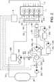
- Fig. 2depicts components of the engine system including the engine 1 which in this example has four cylinders 101-104. It is understood that the engine may have any number of cylinders, in any suitable configuration, such as a V-configuration or an in-line configuration, as in this example.
- the engine systemcomprises an air intake manifold 2 for the engine 1.
- the engine systemfurther comprises a fuel system for an internal combustion engine 1.
- the fuel systemcomprises an electronic control unit 4 configured to control parts of the fuel system as exemplified below, and to thereby perform the steps of a method described below.
- the control unit 4may comprise an electronic data processor and an electronic data storage. It is understood that the control unit 4 may be provided as one single physical unit, or a plurality of physical units arranged to communicate with each other. Also the control unit 4 may form a part of a control system for controlling in addition to the fuel system other functions and sub-systems in the engine system.
- the fuel systemcomprises a liquefied gas tank 301 arranged to store liquefied gas (LNG).
- LNGliquefied gas
- the liquefied gasmay be any suitable type of gaseous fuel; in this example the liquefied gas is natural gas comprising methane. Other possible gases include propane and butane.
- a pressurized gas production unit 306, 351is arranged to produce pressurized gas from the liquefied gas.
- the pressurized gas production unit 306, 351comprises a pressurizing pump 306 is connected to the liquefied gas tank 301.
- the pressurizing pump 306is arranged to receive liquefied gas from the liquefied gas tank 301 and to pressurize the received liquefied gas.
- the pressurizing pump 306is arranged to pressurize the liquefied gas to be at a pressure of at least 400 bar.
- the pressurizing pump 306is arranged to be driven by a hydraulic motor 341.
- the hydraulic motor 341is arranged to be driven by hydraulic fluid pressurized by a hydraulic pump 342 adapted to be driven by a crankshaft of the engine. It is understood that the pressurizing pump 306 may be driven in any suitable alternative manner, e.g. by an electric motor.
- the fuel systemfurther comprises a fuel rail 310 connected to the pressurizing pump 306, and a fuel injector 311-314 at each cylinder 101-104.
- the pressurized gas production unit 306, 351further comprises a heat exchanger 351 is provided between the pressurizing pump 306 and the fuel rail 310. Some of the liquefied gas may be transformed to a gaseous form in the pressurizing pump 306.
- the heat exchanger 351works as a vaporizer to transform any remaining liquefied gas to a gaseous form.
- the heat exchanger 351forms a part of a heat exchange circuit with a heat exchange pump 352 and a reservoir 353 for a heat exchange liquid, e.g. water.
- the heat exchange pump 352is arranged to pump the heat exchange liquid from the reservoir 353 and through the heat exchanger 351.
- a heater(not shown) may be provided to heat the heat exchange liquid.
- the heat exchanger 351is arranged to increase the temperature of the fluid from the pressurizing pump 306 in order to convert any remaining liquefied gas therein to a gaseous form.
- the fuel rail 310is arranged to receive the pressurized gas from the heat exchanger 351 and to deliver the pressurized gas to the fuel injectors 311-314.
- the fuel injectors 311-314are adapted to inject the pressurized gas into the cylinders 101-104. It should be noted that the fuel injectors 311-314 may be arranged to change the fuel injection pressure, e.g. based on the engine load. Thus, the pressure may vary depending on the operational situation of the engine.
- a high pressure buffer tank 361is provided between the heat exchanger 351 and the fuel rail 310.
- the engine systemmay in some embodiments comprise a pilot fuel system (not shown) for injecting a pilot fuel into the cylinders 101-104.
- a pilot fuel systemfor injecting a pilot fuel into the cylinders 101-104.
- Any suitable type of pilot fuelmay be used; e.g. diesel fuel or dimethyl ester (DME).
- the pilot fuel systemmay comprise a pilot fuel tank, a pilot fuel injector at each cylinder, and a pilot fuel pump between the pilot fuel tank and the pilot fuel injectors.
- the respective fuel injector 311-314 and pilot fuel injectormay be provided as separate units, or combined in a single combination injector, as is known per se.
- a mixing unit 307is provided between the liquefied gas tank 301 and the pressurizing pump 306.
- the pressurizing pump 306is arranged to receive the liquefied gas via the mixing unit 307.
- the mixing unit 307is connected to the liquefied gas tank 301 via a liquefied gas connection 323, and to the pressurizing pump 306 via a pump connection 324.
- An excess gas buffer tank 308is arranged to receive excess gas in the form of vaporized gas from the liquefied gas tank 301.
- the fuel systemcomprises a vapor gas connection 321 between the liquefied gas tank 301 and the excess gas buffer tank 308 for the excess gas buffer tank 308 to receive excess gas in the form of the vaporized gas from the liquefied gas tank 301.
- the transport of vaporized gas from the liquefied gas tank 301 to the excess gas buffer tank 308may be controlled by means of a pressure sensor (not shown), e.g. in the liquefied gas tank 301, and a valve (not shown) in the vapor gas connection 321.
- the excess gas buffer tank 308is further arranged to receive excess gas in the form of pressurized gas from the fuel rail 310.
- the fuel systemcomprises a pressurized gas connection 322 between the fuel rail 310 and the excess gas buffer tank 308 for the excess gas buffer tank 308 to receive the excess gas in the form of the pressurized gas from the fuel rail 310.
- the transport of pressurized gas from the fuel rail 310 to the excess gas buffer tank 308may be controlled by means of a pressure sensor (not shown), e.g. in the fuel rail 310, and a valve (not shown) in the pressurized gas connection 322.
- the mixing unit 307is arranged to receive excess gas from the excess gas buffer tank 308 via an excess gas connection 325.
- Combinations of the vapor gas connection 321 and the excess gas connection 325, and of the pressurized gas connection 322 and the excess gas connection 325,are herein also simply referred to as connections.
- the fuel systemfurther comprises an admission valve 331 arranged to control the flow of excess gas to the mixing unit 307.
- the admission valve 331is controllable by the control unit 4.
- the admission valve 331may be controlled so as to allow a plurality of flow levels, or a flow adjustment without any discontinuity, between a fully open and a fully closed position.
- the fuel systemcomprises an excess gas boosting pump 309 arranged to pressurize the excess gas and to deliver the pressurized excess gas to the mixing unit 307.
- the excess gas boosting pump 309is controllable by the control unit 4.
- the fuel systemfurther comprises a delivery control valve 332 arranged to control the flow of liquefied gas to the mixing unit 307.
- the delivery control valve 332is arranged to control the flow through the liquefied gas connection 323.
- the delivery control valve 332is controllable by the control unit 4.
- the delivery control valve 332may be controlled so as to allow a plurality of flow levels, or a flow adjustment without any discontinuity, between a fully open and a fully closed position.
- the fuel systemfurther comprises a delivery pump 302 arranged to pump the liquefied gas through the liquefied gas connection 323, towards the mixing unit 307.
- the delivery pump 302is provided between the liquefied gas tank 301 and the delivery control valve 332.
- the delivery pump 302may be provided between the delivery control valve 332 and the mixing unit 307.
- the mixing unit 307is arranged to mix the excess gas with the liquefied gas received from the liquefied gas tank 301.
- the mixing unit 307presents a mixing chamber 317 arranged to receive the excess gas and the liquefied gas.
- the mixing chamber 317forms an internal cavity of the mixing unit 307.
- the mixing chamber 317presents a rounded, more specifically a spherical shape.
- a nozzle 3171is arranged to be fed by the liquefied gas connection 323. The nozzle 3171 is arranged to spray centrally in an upper portion of the mixing chamber 317 the liquefied gas.
- the mixing chamber 317may be filled with small droplets of the liquefied gas.
- the excess gasis guided with the excess gas connection 325 to an inlet 3172 which is located vertically in the center of the mixing chamber 317.
- the excess gasmay be mixed with the spray of liquefied gas.
- the mix of excess gas and liquefied gasis guided away from the mixing chamber via an outlet 3173 to the pump connection 324, at a bottom region of the mixing chamber 317.
- the mixing chamber 317may have another geometry; e.g. it may be cylindrical, ellipsoidal, dome shaped, cubical or pyramid shaped.
- the control unit 4is arranged to determine the engine load, e.g. in the form an output torque of the engine. This may be done in a manner known per se, e.g. based on the engine rotational speed and the amount of fuel injected by the fuel injectors 311-314.
- the pressurizing pump 306is allowed S1, by control of the delivery control valve 332, to receive liquefied gas via the mixing unit 307.
- the control unit 4determines continuously or repeatedly the engine load. Thereby, the control unit 4 determines S2 whether the engine load is above a threshold value. If the engine load is above the threshold value, the mixing unit 307 is not allowed S3, by control of the admission valve 331 and the excess gas boosting pump 309, to receive excess gas.
- the mixing unit 307is allowed S4, by control of the admission valve 331 and the excess gas boosting pump 309, to receive excess gas.
- the excess gasis allowed S5 to mix in the mixing unit 307 with the liquefied gas received from the liquefied gas tank 301.
- the relationship between the flow of excess gas to the mixing unit 307 and the flow of liquefied gas to the mixing unit 307is determined based on the engine load. I.e. it is determined based on the engine load whether any excess gas flow is allowed to the mixing unit.
- the relationship between the flow of excess gas to the mixing unit 307 and the flow of liquefied gas to the mixing unit 307is determined based on the engine load.
- the excess gas flowis controlled S5 with the admission valve 331.
- the admission valve 331is controlled so as to provide a relatively large ratio of excess gas flow to liquefied gas flow.
- the admission valve 331is controlled so as to reduce the ratio of excess gas flow to liquefied gas flow.
- the flow of excess gas to the mixing unit 307is considerably smaller than the flow of liquefied gas to the mixing unit 307.
- the excess gas flowmay be no more than 15% or no more than 10% or the liquefied gas flow.
- the ratio of excess gas flow to liquefied gas flowmay be determined based on some other operational condition of the vehicle, for example an inclination of a road on which the vehicle is travelling.
- the road inclinationmay be determined e.g. by means of an inclination senor in a transmission (not shown) of the vehicle. Based on such inclination information, it may be determined whether the vehicle is in an engine braking situation, e.g. in a downhill inclination of the road. In an engine braking situation, the admission valve 331 may be controlled so as to allow a relatively large ratio of excess gas flow to liquefied gas flow.
- a predicted inclination of the road on which the vehicle is travellingmay be determined. Such a prediction may be made e.g. by means of map data of a device of the Global Positioning System (GPS).
- GPSGlobal Positioning System
- the fuel systemmay be controlled so that the pressure in the high pressure buffer tank 361 between the heat exchanger 351 and the fuel rail 310 is relatively low.
- the relationship between the flow of excess gas to the mixing unit 307 and the flow of liquefied gas to the mixing unit 307may be controlled so as to be relatively high, whereby the pressure in the high pressure buffer tank 361 is increased.
- the pressure of the excess gas delivered to the mixing unit 307is controlled S6 to not be lower than the pressure of the liquefied gas delivered to the mixing unit 307.
- the excess gas pressureis determined by means of a pressure sensor 401 upstream of the mixing unit 307.
- the liquefied gas pressuremay be determined by a pressure sensor (not shown) in the liquefied gas tank 301.
- the excess gas boosting pump 309is used to avoid that the excess gas pressure is lower than the liquefied gas pressure.
- the mixing unit 307is not allowed S3, by control of the admission valve 331 and the excess gas boosting pump 309, to receive excess gas.
Landscapes
- Engineering & Computer Science (AREA)
- Chemical & Material Sciences (AREA)
- Mechanical Engineering (AREA)
- General Engineering & Computer Science (AREA)
- Combustion & Propulsion (AREA)
- Chemical Kinetics & Catalysis (AREA)
- General Chemical & Material Sciences (AREA)
- Oil, Petroleum & Natural Gas (AREA)
- Life Sciences & Earth Sciences (AREA)
- Sustainable Development (AREA)
- Sustainable Energy (AREA)
- Transportation (AREA)
- Output Control And Ontrol Of Special Type Engine (AREA)
- Filling Or Discharging Of Gas Storage Vessels (AREA)
Description
- The invention relates to a fuel system for an internal combustion engine, the fuel system comprising a liquefied gas tank arranged to store liquefied gas (LNG).
- The invention can be applied in heavy-duty vehicles, such as trucks, buses and construction equipment, e.g. working machines. The invention can also be applied to cars. Although the invention will be described with respect to a truck, the invention is not restricted to this particular vehicle type.
- High Pressure Gas Injection (HPGI) internal combustion engines have been the subject of increasing interest and use for some time. The HPGI technology is also known as the High Pressure Direct Injection (HPDI) technology. It allows natural gas engines to operate at the same efficiency and power as modern heavy-duty diesel engines, but with a better fuel efficiency and reduced greenhouse gas emissions depending on the composition of the gaseous fuel used. The HPGI heavy duty gas engine technology is based on direct in-cylinder injection of gaseous fuel providing conditions for mixing limited combustion, or mixing controlled combustion, similar to the process in conventional diesel engines. The fuel is stored in a liquefied gas tank, where it is kept at a low temperature to keep the fuel in liquid form. A high pressure pump and vaporizer transforms the fuel to gaseous form. The gas is supplied to the cylinders using high pressure gas injectors. Additional pilot quantities of diesel fuel are injected in order to accomplish ignition.
- In HPGI engines there are usually requirements to dispense of high pressure gas, e.g. during a rapid pressure decrease in the injection system due to a decrease in the engine load, or during an engine stoppage. A need to vent boil-off gas from the liquefied gaseous fuel storage is another common reason for disposing of gas. Such disposal will create an environmental disturbance, since it involves emitting unburned hydrocarbons into the atmosphere. In case of methane gas such emissions also cause unwanted contributions to global warming. Some fuel filling stations are equipped for received vaporized gas when refuelling. In any case, fuel disposal, whether it is of high pressure gas from the injection system or of vent off gas from the fuel storage, creates a loss to the operator of a vehicle in which the engine is provided.
- It is known, e.g. from
EP1785618A1 , to return superfluous gaseous fuel to the fuel storage tank. Where the returned fuel is in gaseous form, e.g. compressed natural gas (CNG), a problem with returning the fuel to a liquefied gas tank is that the returned relatively warm fuel will increase the temperature and pressure in the tank, which reduces a hold time which in turn advances a need to vent vaporized fuel from the tank. EP1990272A1 discloses a fuel gas supply system of a liquefied natural gas (LNG) carrier for supplying fuel gas to a high-pressure gas injection engine of an LNG carrier, wherein LNG is extracted from an LNG storage tank of the LNG carrier, compressed at a high pressure, gasified, and then supplied to the high-pressure gas injection engine.- An object of the invention is to reduce emissions from fuel systems of internal combustion engines with high pressure gas injection. Another object of the invention is to reduce losses from fuel systems of internal combustion engines with high pressure gas injection.
- This object is reached with a fuel system for an internal combustion engine, the fuel system comprising a liquefied gas tank arranged to store liquefied gas (LNG), and a pressurized gas production unit connected to the liquefied gas tank, the pressurized gas production unit being arranged to receive liquefied gas from the liquefied gas tank and to produce pressurized gas from the liquefied gas, the fuel system further comprising a fuel rail connected to the pressurized gas production unit and arranged to receive the pressurized gas and to deliver the pressurized gas to a fuel injector adapted to inject the pressurized gas into a cylinder of the engine, wherein a mixing unit is provided between the liquefied gas tank and the pressurized gas production unit whereby the pressurized gas production unit is arranged to receive the liquefied gas via the mixing unit, the mixing unit being arranged to receive excess gas in the form of vaporized gas from the liquefied gas tank and/or pressurized gas from the fuel rail, the mixing unit being arranged to mix the excess gas with the liquefied gas received from the liquefied gas tank, wherein the mixing unit presents a mixing chamber arranged to receive the excess gas and the liquefied gas.
- The invention provides for mixing the excess gas with the liquefied gas between the liquefied gas tank and the pressurized gas production unit. This mixing may involve mixing a liquid, i.e. the liquefied gas, with a gas, i.e. the excess gas. The mixing chamber of the mixing unit provides for the mixing of the excess gas with the liquefied gas to be secured. The invention provides for the pressurized gas production unit to process the excess gas as well as the liquefied gas. As a result, the excess gas does not need to be returned to the liquefied gas tank and the risk of increased vaporization in the tank may be avoided. Thereby losses of fuel may be reduced or avoided. Also, venting gaseous to the atmosphere may be reduced or avoided. Thus, the invention may substantially reduce environmental disturbances caused by excess gaseous fuel in high pressure gas injection engines. Further, the invention may substantially increase the amount of useful work provided by the fuel due to the excess gas being combusted in the engine.
- The mixing chamber may form an internal cavity of the mixing unit. The mixing chamber may present an at least partly rounded shape. Thereby, the presence of sharp corners in the internal cavity of the mixing chamber is reduced or eliminated, and this may promote an even distribution of the liquefied gas, which in turn is beneficial for thoroughly mixing the liquefied gas with the excess gas.
- Preferably, the mixing chamber presents a spherical shape. Thereby, the presence of sharp corners in the internal cavity of the mixing chamber is eliminated, and a thorough mix of the liquefied gas with the excess gas may be further secured. It should be noted however, that the mixing chamber may present a variety of alternative geometries, e.g. cylindrical, ellipsoidal, dome shaped, cubical or pyramid shaped.
- The mixing unit is arranged to receive the liquefied gas from the liquefied gas tank via a liquefied gas connection, and a nozzle is arranged to be fed by the liquefied gas connection and to spray the liquefied gas into the mixing chamber. The nozzle may be fed by the pressure in the liquefied gas tank, and/or by a delivery pump arranged to pump the liquefied gas through the liquefied gas connection towards the mixing unit. The nozzle may dispense the liquefied gas into the mixing chamber in the form of droplets. Such droplets may be small enough to promote a thorough mix of the liquefied gas with the excess gas.
- Preferably, the nozzle is arranged to introduce the spray of liquefied gas in an upper portion of the mixing chamber. Thereby, gravity may assist to distribute the liquefied gas in the mixing chamber. Thereby, at least a major portion of the mixing chamber may be filled with droplets of the liquefied gas. Thus, a thorough mix of the liquefied gas with the excess gas is further promoted. The nozzle is preferably centered in a horizontal cross-section of the mixing chamber.
- Preferably, the mixing unit is arranged to receive excess gas at an inlet to the mixing chamber, which inlet is located below the nozzle. Thereby, the excess gas may advantageously be introduced into an area where the concentration of liquefied gas droplets is higher than elsewhere in the mixing chamber. This provides an additional promotion of a thorough mix of the liquefied gas with the excess gas.
- The mixing unit is arranged to guide a mix of the liquefied gas and the excess gas away from the mixing chamber via an outlet at a bottom region of the mixing chamber. Thereby, the outlet is beneficially located where the mix of the liquefied gas and the excess gas is moved by the assistance of gravity. Where the nozzle is arranged to introduce the spray of liquefied gas in an upper portion of the mixing chamber, and the mixing unit is arranged to receive excess gas at an inlet to the mixing chamber, which inlet is located below the nozzle, such a location of the outlet may provide for the liquefied gas and the excess gas to mix thoroughly before being guided away from the mixing chamber.
- Preferably, the fuel system further comprises an admission valve arranged to control the flow of excess gas to the mixing unit. Thereby a control of the ratio of the excess gas flow to the liquefied gas flow may be provided by suitable control of the admission valve.
- Preferably, the fuel system further comprises a delivery control valve arranged to control the flow of liquefied gas to the mixing unit. Thereby a further control of the ratio of the excess gas flow to the liquefied gas flow may be provided by suitable control of the delivery control valve.
- Preferably, the fuel system further comprises a connection between the liquefied gas tank and the mixing unit for the mixing unit to receive the excess gas in the form of the vaporized gas from the liquefied gas tank. Thereby vapor gas from the liquefied gas tank may be transported to be combusted in the engine, thereby avoiding the need to vent it.
- Preferably, the fuel system further comprises a connection between the fuel rail and the mixing unit for the mixing unit to receive the excess gas in the form of the pressurized gas from the fuel rail. Thereby superfluous pressurized gas from the fuel rail may be transported back to the mixing unit and once again to the fuel rail to be combusted in the engine, thereby avoiding the need to vent it.
- Preferably, the fuel system comprises an excess gas buffer tank arranged to receive the excess gas from the liquefied gas tank and/or from the fuel rail before the excess gas is delivered to the mixing unit. Thereby, the excess gas may be temporarily stored before introduced to the mixing unit. This provides for controlling the relationship between the flow of excess gas to the mixing unit and the flow of liquefied gas to the mixing unit at least partly based on a determined nature of the operational condition of the vehicle, as exemplified below.
- Preferably, the fuel system comprises an excess gas boosting pump arranged to pressurize the excess gas and to deliver the pressurized excess gas to the mixing unit. Thereby it may be secured that the excess gas is not delivered to the mixing unit at a pressure that is lower than the pressure of the liquefied gas delivered to the mixing unit, by operation of the excess gas boosting pump when needed. The excess gas from the fuel rail may be delivered from the fuel rail at a high pressure. However, the operation of the excess gas boosting pump may be needed where the excess gas is delivered exclusively as vent off gas from the liquefied gas tank.
- Preferably, the pressurized gas production unit is arranged to produce the pressurized gas to be at a pressure of at least 400 bar, or at least 500 bar. Preferably, the pressurized gas production unit comprises a pressurizing pump arranged to be driven by a hydraulic motor. Preferably, the hydraulic motor is arranged to be driven by hydraulic fluid pressurized by a hydraulic pump adapted to be driven by a crankshaft of the engine. Thereby it may be secured that the engine receives the pressurized gas at a suitable pressure level depending on requirements on the fuel system, e.g. by control of the hydraulic pressure to the hydraulic motor. As a comparison, if the pressurizing pump is arranged to be driven directly by the crankshaft of the engine, the work of the pressurizing pump will be dependent on the engine rotational speed. However, a benefit of the pressurizing pump being arranged to be driven directly by the crankshaft, e.g. via a gear wheel connection or a belt, is that operating losses may be kept low.
- Preferably, the pressurized gas production unit comprises a pressurizing pump arranged to pressurize the received liquefied gas, and a heat exchanger provided between the pressurizing pump and the fuel rail. Thereby an efficient engine operation may be secured since the heat exchanger may provide a control of the temperature of the fuel delivered to the fuel rail, to thereby control the density of the gaseous fuel. A known density of the gaseous fuel will make it easier to control the energy provided with the fuel by controlling the volume of delivered fuel.
- Further advantages and advantageous features of the invention are disclosed in the following description.
- With reference to the appended drawings, below follows a more detailed description of embodiments of the invention cited as examples. In the drawings:
Fig. 1 is a partially sectioned side view of a vehicle in the form of a truck.Fig. 2 is a diagram of an engine system in the vehicle infig. 1 .Fig. 3 shows a detail in the engine system infig. 2 .Fig. 4 is a flow diagram depicting steps in a method in the engine system infig. 2 .Fig. 1 shows a vehicle in the form of a truck, or a tractor for a semitrailer. It should be noted that the vehicle can be of a variety of alternative types, e.g. it may be a car, a bus, or a working machine such as a wheel loader. The vehicle comprises an engine system with a high pressure gas injection (HPGI)internal combustion engine 1. The engine is adapted to a diesel cycle.Fig. 2 depicts components of the engine system including theengine 1 which in this example has four cylinders 101-104. It is understood that the engine may have any number of cylinders, in any suitable configuration, such as a V-configuration or an in-line configuration, as in this example. The engine system comprises an air intake manifold 2 for theengine 1.- The engine system further comprises a fuel system for an
internal combustion engine 1. The fuel system comprises an electronic control unit 4 configured to control parts of the fuel system as exemplified below, and to thereby perform the steps of a method described below. The control unit 4 may comprise an electronic data processor and an electronic data storage. It is understood that the control unit 4 may be provided as one single physical unit, or a plurality of physical units arranged to communicate with each other. Also the control unit 4 may form a part of a control system for controlling in addition to the fuel system other functions and sub-systems in the engine system. - The fuel system comprises a liquefied
gas tank 301 arranged to store liquefied gas (LNG). The liquefied gas may be any suitable type of gaseous fuel; in this example the liquefied gas is natural gas comprising methane. Other possible gases include propane and butane. - A pressurized
gas production unit gas production unit pump 306 is connected to the liquefiedgas tank 301. The pressurizingpump 306 is arranged to receive liquefied gas from the liquefiedgas tank 301 and to pressurize the received liquefied gas. In this example, the pressurizingpump 306 is arranged to pressurize the liquefied gas to be at a pressure of at least 400 bar. - The pressurizing
pump 306 is arranged to be driven by ahydraulic motor 341. Thehydraulic motor 341 is arranged to be driven by hydraulic fluid pressurized by ahydraulic pump 342 adapted to be driven by a crankshaft of the engine. It is understood that the pressurizingpump 306 may be driven in any suitable alternative manner, e.g. by an electric motor. - The fuel system further comprises a
fuel rail 310 connected to the pressurizingpump 306, and a fuel injector 311-314 at each cylinder 101-104. - The pressurized
gas production unit heat exchanger 351 is provided between the pressurizingpump 306 and thefuel rail 310. Some of the liquefied gas may be transformed to a gaseous form in the pressurizingpump 306. Theheat exchanger 351 works as a vaporizer to transform any remaining liquefied gas to a gaseous form. - The
heat exchanger 351 forms a part of a heat exchange circuit with aheat exchange pump 352 and areservoir 353 for a heat exchange liquid, e.g. water. Theheat exchange pump 352 is arranged to pump the heat exchange liquid from thereservoir 353 and through theheat exchanger 351. A heater (not shown) may be provided to heat the heat exchange liquid. Thereby, theheat exchanger 351 is arranged to increase the temperature of the fluid from the pressurizingpump 306 in order to convert any remaining liquefied gas therein to a gaseous form. - The
fuel rail 310 is arranged to receive the pressurized gas from theheat exchanger 351 and to deliver the pressurized gas to the fuel injectors 311-314. The fuel injectors 311-314 are adapted to inject the pressurized gas into the cylinders 101-104. It should be noted that the fuel injectors 311-314 may be arranged to change the fuel injection pressure, e.g. based on the engine load. Thus, the pressure may vary depending on the operational situation of the engine. - A high
pressure buffer tank 361 is provided between theheat exchanger 351 and thefuel rail 310. - The engine system may in some embodiments comprise a pilot fuel system (not shown) for injecting a pilot fuel into the cylinders 101-104. Any suitable type of pilot fuel may be used; e.g. diesel fuel or dimethyl ester (DME). The pilot fuel system may comprise a pilot fuel tank, a pilot fuel injector at each cylinder, and a pilot fuel pump between the pilot fuel tank and the pilot fuel injectors. In each cylinder 101-104 the respective fuel injector 311-314 and pilot fuel injector may be provided as separate units, or combined in a single combination injector, as is known per se.
- A mixing
unit 307 is provided between the liquefiedgas tank 301 and the pressurizingpump 306. Thus, the pressurizingpump 306 is arranged to receive the liquefied gas via themixing unit 307. Thereby, themixing unit 307 is connected to the liquefiedgas tank 301 via a liquefiedgas connection 323, and to the pressurizingpump 306 via apump connection 324. - An excess
gas buffer tank 308 is arranged to receive excess gas in the form of vaporized gas from the liquefiedgas tank 301. For this the fuel system comprises avapor gas connection 321 between the liquefiedgas tank 301 and the excessgas buffer tank 308 for the excessgas buffer tank 308 to receive excess gas in the form of the vaporized gas from the liquefiedgas tank 301. The transport of vaporized gas from the liquefiedgas tank 301 to the excessgas buffer tank 308 may be controlled by means of a pressure sensor (not shown), e.g. in the liquefiedgas tank 301, and a valve (not shown) in thevapor gas connection 321. - The excess
gas buffer tank 308 is further arranged to receive excess gas in the form of pressurized gas from thefuel rail 310. For this the fuel system comprises a pressurized gas connection 322 between thefuel rail 310 and the excessgas buffer tank 308 for the excessgas buffer tank 308 to receive the excess gas in the form of the pressurized gas from thefuel rail 310. The transport of pressurized gas from thefuel rail 310 to the excessgas buffer tank 308 may be controlled by means of a pressure sensor (not shown), e.g. in thefuel rail 310, and a valve (not shown) in the pressurized gas connection 322. - The
mixing unit 307 is arranged to receive excess gas from the excessgas buffer tank 308 via anexcess gas connection 325. Combinations of thevapor gas connection 321 and theexcess gas connection 325, and of the pressurized gas connection 322 and theexcess gas connection 325, are herein also simply referred to as connections. - The fuel system further comprises an
admission valve 331 arranged to control the flow of excess gas to themixing unit 307. Theadmission valve 331 is controllable by the control unit 4. Theadmission valve 331 may be controlled so as to allow a plurality of flow levels, or a flow adjustment without any discontinuity, between a fully open and a fully closed position. - The fuel system comprises an excess
gas boosting pump 309 arranged to pressurize the excess gas and to deliver the pressurized excess gas to themixing unit 307. The excessgas boosting pump 309 is controllable by the control unit 4. - The fuel system further comprises a delivery control valve 332 arranged to control the flow of liquefied gas to the
mixing unit 307. The delivery control valve 332 is arranged to control the flow through the liquefiedgas connection 323. The delivery control valve 332 is controllable by the control unit 4. The delivery control valve 332 may be controlled so as to allow a plurality of flow levels, or a flow adjustment without any discontinuity, between a fully open and a fully closed position. - The fuel system further comprises a
delivery pump 302 arranged to pump the liquefied gas through the liquefiedgas connection 323, towards the mixingunit 307. In this embodiment thedelivery pump 302 is provided between the liquefiedgas tank 301 and the delivery control valve 332. In alternative embodiments thedelivery pump 302 may be provided between the delivery control valve 332 and themixing unit 307. - Reference is made also to
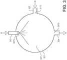
fig. 3 . Themixing unit 307 is arranged to mix the excess gas with the liquefied gas received from the liquefiedgas tank 301. For this the mixingunit 307 presents a mixingchamber 317 arranged to receive the excess gas and the liquefied gas. As understood fromfig. 3 , the mixingchamber 317 forms an internal cavity of themixing unit 307. The mixingchamber 317 presents a rounded, more specifically a spherical shape. Anozzle 3171 is arranged to be fed by the liquefiedgas connection 323. Thenozzle 3171 is arranged to spray centrally in an upper portion of the mixingchamber 317 the liquefied gas. Thereby, at least a major portion of the mixingchamber 317 may be filled with small droplets of the liquefied gas. The excess gas is guided with theexcess gas connection 325 to aninlet 3172 which is located vertically in the center of the mixingchamber 317. Thereby the excess gas may be mixed with the spray of liquefied gas. The mix of excess gas and liquefied gas is guided away from the mixing chamber via anoutlet 3173 to thepump connection 324, at a bottom region of the mixingchamber 317. - It should be noted that in alternative embodiments, the mixing
chamber 317 may have another geometry; e.g. it may be cylindrical, ellipsoidal, dome shaped, cubical or pyramid shaped. - The control unit 4 is arranged to determine the engine load, e.g. in the form an output torque of the engine. This may be done in a manner known per se, e.g. based on the engine rotational speed and the amount of fuel injected by the fuel injectors 311-314.
- With reference to
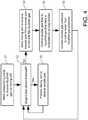
fig. 4 , a method of controlling the fuel system will be described. During operation of theengine 1, the pressurizingpump 306 is allowed S1, by control of the delivery control valve 332, to receive liquefied gas via themixing unit 307. The control unit 4 determines continuously or repeatedly the engine load. Thereby, the control unit 4 determines S2 whether the engine load is above a threshold value. If the engine load is above the threshold value, themixing unit 307 is not allowed S3, by control of theadmission valve 331 and the excessgas boosting pump 309, to receive excess gas. - If the engine load is below the threshold value, the
mixing unit 307 is allowed S4, by control of theadmission valve 331 and the excessgas boosting pump 309, to receive excess gas. Thereby, the excess gas is allowed S5 to mix in themixing unit 307 with the liquefied gas received from the liquefiedgas tank 301. Thereby, the relationship between the flow of excess gas to themixing unit 307 and the flow of liquefied gas to themixing unit 307 is determined based on the engine load. I.e. it is determined based on the engine load whether any excess gas flow is allowed to the mixing unit. - In addition, where the excess gas is allowed to the mixing unit, the relationship between the flow of excess gas to the
mixing unit 307 and the flow of liquefied gas to themixing unit 307 is determined based on the engine load. The excess gas flow is controlled S5 with theadmission valve 331. At very low engine loads or at negative loads, e.g. at idling or at engine braking, theadmission valve 331 is controlled so as to provide a relatively large ratio of excess gas flow to liquefied gas flow. As the load increases towards the threshold value, theadmission valve 331 is controlled so as to reduce the ratio of excess gas flow to liquefied gas flow. In any case, the flow of excess gas to themixing unit 307 is considerably smaller than the flow of liquefied gas to themixing unit 307. For example, the excess gas flow may be no more than 15% or no more than 10% or the liquefied gas flow. - Alternatively, instead of, or in addition to, the engine load, the ratio of excess gas flow to liquefied gas flow may be determined based on some other operational condition of the vehicle, for example an inclination of a road on which the vehicle is travelling. The road inclination may be determined e.g. by means of an inclination senor in a transmission (not shown) of the vehicle. Based on such inclination information, it may be determined whether the vehicle is in an engine braking situation, e.g. in a downhill inclination of the road. In an engine braking situation, the
admission valve 331 may be controlled so as to allow a relatively large ratio of excess gas flow to liquefied gas flow. - A predicted inclination of the road on which the vehicle is travelling may be determined. Such a prediction may be made e.g. by means of map data of a device of the Global Positioning System (GPS). As suggested above, thereby, where a prediction of a downhill road inclination is made, the fuel system may be controlled so that the pressure in the high
pressure buffer tank 361 between theheat exchanger 351 and thefuel rail 310 is relatively low. When the vehicle reaches the downhill inclination, and enters an engine brake mode, the relationship between the flow of excess gas to themixing unit 307 and the flow of liquefied gas to themixing unit 307 may be controlled so as to be relatively high, whereby the pressure in the highpressure buffer tank 361 is increased. - Regardless of the ratio of excess gas flow to liquefied gas flow, the pressure of the excess gas delivered to the
mixing unit 307 is controlled S6 to not be lower than the pressure of the liquefied gas delivered to themixing unit 307. The excess gas pressure is determined by means of apressure sensor 401 upstream of themixing unit 307. The liquefied gas pressure may be determined by a pressure sensor (not shown) in the liquefiedgas tank 301. The excessgas boosting pump 309 is used to avoid that the excess gas pressure is lower than the liquefied gas pressure. - As stated the engine load is continuously or repeatedly determined S2, and where the engine load increases to be above the threshold value, the
mixing unit 307 is not allowed S3, by control of theadmission valve 331 and the excessgas boosting pump 309, to receive excess gas. - It is to be understood that the present invention is not limited to the embodiments described above and illustrated in the drawings; rather, the skilled person will recognize that many changes and modifications may be made within the scope of the appended claims.
Claims (17)
- A fuel system for an internal combustion engine (1), the fuel system comprising a liquefied gas tank (301) arranged to store liquefied gas, and a pressurized gas production unit (306, 351) connected to the liquefied gas tank (301), the pressurized gas production unit (306, 351) being arranged to receive liquefied gas from the liquefied gas tank (301) and to produce pressurized gas from the liquefied gas, wherein a mixing unit (307) is provided between the liquefied gas tank (301) and the pressurized gas production unit (306, 351) whereby the pressurized gas production unit (306, 351) is arranged to receive the liquefied gas via the mixing unit (307), wherein the mixing unit (307) is arranged to receive excess gas in the form of vaporized gas from the liquefied gas tank (301) and/or pressurized gas from a fuel rail (310) of the fuel system, the fuel rail (310) being connected to the pressurized gas production unit (306, 351) and arranged to receive the pressurized gas and to deliver the pressurized gas to a fuel injector (311-314) adapted to inject the pressurized gas into a cylinder (101-104) of the engine, the mixing unit (307) being arranged to mix excess gas with the liquefied gas received from the liquefied gas tank (301), wherein the mixing unit (307) presents a mixing chamber (317) arranged to receive the excess gas and the liquefied gas, wherein the mixing unit (307) is arranged to receive the liquefied gas from the liquefied gas tank (301) via a liquefied gas connection (323),characterized in that a nozzle (3171) is arranged to be fed by the liquefied gas connection (323) and to spray the liquefied gas into the mixing chamber (317), wherein the mixing unit (307) is arranged to guide a mix of the liquefied gas and the excess gas away from the mixing chamber (317) to the pressurized gas production unit (306, 351) via an outlet (3173) at a bottom region of the mixing chamber (317).
- A fuel system according to claim 1,characterized in that the mixing chamber (317) forms an internal cavity of the mixing unit (307).
- A fuel system according to any one of the preceding claims,characterized in that the mixing chamber (317) presents an at least partly rounded shape.
- A fuel system according to any one of the preceding claims,characterized in that the mixing chamber (317) presents a spherical shape.
- A fuel system according to any one of the preceding claims,characterized in that the nozzle (3171) is arranged to introduce the spray of liquefied gas in an upper portion of the mixing chamber (317).
- A fuel system according to any one of the preceding claims,characterized in that the mixing unit (307) is arranged to receive excess gas at an inlet (3172) to the mixing chamber, which inlet is located below the nozzle (3171).
- A fuel system according to any one of the preceding claims,characterized in that the fuel system further comprises an admission valve (331) arranged to control the flow of excess gas to the mixing unit (307).
- A fuel system according to any one of the preceding claims,characterized in that the fuel system further comprises a delivery control valve (332) arranged to control the flow of liquefied gas to the mixing unit (307).
- A fuel system according to any one of the preceding claims,characterized in that the fuel system further comprises a connection (321, 325) between the liquefied gas tank (301) and the mixing unit (307) for the mixing unit to receive the excess gas in the form of the vaporized gas from the liquefied gas tank (301).
- A fuel system according to any one of the preceding claims,characterized in that the fuel system further comprises a connection (322, 325) between the fuel rail (310) and the mixing unit (307) for the mixing unit to receive the excess gas in the form of the pressurized gas from the fuel rail (310).
- A fuel system according to any one of the preceding claims,characterized in that the fuel system comprises an excess gas buffer tank (308) arranged to receive the excess gas from the liquefied gas tank (301) and/or from the fuel rail (310) before the excess gas is delivered to the mixing unit (307).
- A fuel system according to any one of the preceding claims,characterized in that the fuel system comprises an excess gas boosting pump (309) arranged to pressurize the excess gas and to deliver the pressurized excess gas to the mixing unit (307).
- A fuel system according to any one of the preceding claims,characterized in that the pressurized gas production unit (306, 351) is arranged to produce the pressurized gas to be at a pressure of at least 400 bar.
- A fuel system according to any one of the preceding claims,characterized in that the pressurized gas production unit (306, 351) comprises a pressurizing pump (306) arranged to be driven by a hydraulic motor (341).
- A fuel system according to claim 14,characterized in that the hydraulic motor (341) is arranged to be driven by hydraulic fluid pressurized by a hydraulic pump (342) adapted to be driven by a crankshaft of the engine.
- A fuel system according to any one of the preceding claims,characterized in that the pressurized gas production unit (306, 351) comprises a pressurizing pump (306) arranged to pressurize the received liquefied gas, and a heat exchanger (351) provided between the pressurizing pump (306) and the fuel rail (310).
- A vehicle comprising a fuel system according to any one of claims 1-16.
Applications Claiming Priority (1)
| Application Number | Priority Date | Filing Date | Title |
|---|---|---|---|
| PCT/EP2017/056268WO2018166603A1 (en) | 2017-03-16 | 2017-03-16 | A fuel system for an internal combustion engine |
Publications (2)
| Publication Number | Publication Date |
|---|---|
| EP3596328A1 EP3596328A1 (en) | 2020-01-22 |
| EP3596328B1true EP3596328B1 (en) | 2021-01-13 |
Family
ID=58314257
Family Applications (1)
| Application Number | Title | Priority Date | Filing Date |
|---|---|---|---|
| EP17710958.4AActiveEP3596328B1 (en) | 2017-03-16 | 2017-03-16 | A fuel system for an internal combustion engine |
Country Status (4)
| Country | Link |
|---|---|
| US (1) | US10865740B2 (en) |
| EP (1) | EP3596328B1 (en) |
| CN (1) | CN110402329B (en) |
| WO (1) | WO2018166603A1 (en) |
Families Citing this family (5)
| Publication number | Priority date | Publication date | Assignee | Title |
|---|---|---|---|---|
| DE102015215939B4 (en)* | 2015-08-20 | 2021-02-04 | Mtu Friedrichshafen Gmbh | Method for generating a fuel composition and for operating an internal combustion engine |
| US11850936B2 (en)* | 2016-06-15 | 2023-12-26 | Volvo Truck Corporation | Gas tank arrangement |
| CH717460A1 (en) | 2020-05-28 | 2021-11-30 | Liebherr Machines Bulle Sa | System for providing a gaseous fuel. |
| FR3110936B1 (en)* | 2020-05-28 | 2022-06-17 | Safran | Device for regulating the pressure of an aircraft cryogenic fuel tank. |
| FR3148285A1 (en)* | 2023-04-26 | 2024-11-01 | Airbus Operations | SYSTEM FOR RECOVERING GASEOUS DIHYDROGEN PRODUCED IN A LIQUID DIHYDROGEN DISTRIBUTION LINE OF AN AIRCRAFT |
Family Cites Families (26)
| Publication number | Priority date | Publication date | Assignee | Title |
|---|---|---|---|---|
| US5408957A (en) | 1993-04-28 | 1995-04-25 | Crowley; Timothy J. | Continuous combustible gas injection into conventionally fueled internal combustion engines |
| US5421161A (en)* | 1993-09-27 | 1995-06-06 | Minnesota Valley Engineering, Inc. | Storage system for cryogenic fluids |
| NL1009261C2 (en)* | 1998-05-26 | 1999-12-03 | Vialle Beheer B V | Fuel system for an internal combustion engine. |
| JP2005337019A (en) | 2004-05-24 | 2005-12-08 | Nikki Co Ltd | Liquefied gas fuel supply device |
| DE102005054451A1 (en) | 2005-11-13 | 2007-05-16 | Entwicklungsbuero Fuer Umweltf | Fuel cooling system for internal combustion engines |
| KR100835090B1 (en)* | 2007-05-08 | 2008-06-03 | 대우조선해양 주식회사 | Fuel gas supply system and method of LG carrier |
| KR101076266B1 (en)* | 2007-07-19 | 2011-10-26 | 대우조선해양 주식회사 | System for supplying fuel gas in lng carrier |
| DE102007042158A1 (en) | 2007-09-05 | 2009-03-12 | Man Diesel Se | Gas supply system for a gas-fueled internal combustion engine |
| DE202009017653U1 (en) | 2009-12-28 | 2011-05-12 | Greshake, Hermann | Autogas plant with a conveyor unit |
| US20120097127A1 (en) | 2010-10-25 | 2012-04-26 | Joseph Carl Firey | Separate igniter fuel injection system |
| KR101106088B1 (en)* | 2011-03-22 | 2012-01-18 | 대우조선해양 주식회사 | Non-explosive Mixed Refrigerants Used in Reliquefaction Equipment of Fuel Supply Systems for High Pressure Natural Gas Injection Engines |
| DE102012002425B4 (en)* | 2012-02-09 | 2014-03-20 | Entec Consulting Gmbh | Device for supplying a mixed fuel to combustion chambers of a diesel engine and a method for producing a mixed fuel |
| KR101386543B1 (en)* | 2012-10-24 | 2014-04-18 | 대우조선해양 주식회사 | System for treating boil-off gas for a ship |
| KR101277965B1 (en)* | 2013-02-19 | 2013-06-27 | 현대중공업 주식회사 | A fuel gas supply system of liquefied natural gas |
| KR101290430B1 (en)* | 2013-04-24 | 2013-07-26 | 현대중공업 주식회사 | A fuel gas supply system of liquefied natural gas |
| JP2014227917A (en) | 2013-05-22 | 2014-12-08 | 本田技研工業株式会社 | Vehicle including internal combustion engine for gas fuel |
| JP2014238071A (en)* | 2013-06-10 | 2014-12-18 | いすゞ自動車株式会社 | Mixed fuel supply system for internal combustion engine, vehicle and mixed fuel supply method for internal combustion engine |
| CN203702377U (en)* | 2014-03-04 | 2014-07-09 | 广西玉柴机器股份有限公司 | High-power LNG engine gas supply system |
| CN204572245U (en)* | 2015-01-04 | 2015-08-19 | 襄阳京泰汽配有限责任公司 | A kind of gas-fueled vehicles |
| US10030610B2 (en)* | 2015-03-20 | 2018-07-24 | Progress Rail Locomotive Inc. | Fuel system for an engine |
| WO2016172803A1 (en)* | 2015-04-30 | 2016-11-03 | Westport Power Inc. | Intelligent pressure management system for cryogenic fluid systems |
| SG11201710005RA (en)* | 2015-06-02 | 2018-01-30 | Daewoo Shipbuilding & Marine | Ship |
| JP6350445B2 (en)* | 2015-08-17 | 2018-07-04 | 株式会社デンソー | Fuel supply system |
| CN105888794A (en)* | 2016-05-12 | 2016-08-24 | 上海海事大学 | Device and method for achieving pollution-free emission of tail gas of liquefied natural gas marine diesel engine |
| US11149981B2 (en)* | 2017-11-20 | 2021-10-19 | Atlantic, Gulf & Pacific Company Of Manila, Inc. | Systems for vaporizing that include marinized vaporizer units, and methods for making and using such systems |
| US10865741B2 (en)* | 2018-07-30 | 2020-12-15 | Lg Electronics Inc. | Engine drive apparatus |
- 2017
- 2017-03-16EPEP17710958.4Apatent/EP3596328B1/enactiveActive
- 2017-03-16USUS16/493,825patent/US10865740B2/enactiveActive
- 2017-03-16CNCN201780088368.XApatent/CN110402329B/enactiveActive
- 2017-03-16WOPCT/EP2017/056268patent/WO2018166603A1/ennot_activeCeased
Non-Patent Citations (1)
| Title |
|---|
| None* |
Also Published As
| Publication number | Publication date |
|---|---|
| US20200080519A1 (en) | 2020-03-12 |
| CN110402329A (en) | 2019-11-01 |
| EP3596328A1 (en) | 2020-01-22 |
| US10865740B2 (en) | 2020-12-15 |
| CN110402329B (en) | 2021-06-29 |
| WO2018166603A1 (en) | 2018-09-20 |
Similar Documents
| Publication | Publication Date | Title |
|---|---|---|
| EP3596328B1 (en) | A fuel system for an internal combustion engine | |
| CN103189618B (en) | Two engine system with a gaseous fuel stored in liquefied form | |
| CN101963113B (en) | Engine and control method thereof | |
| US9624871B2 (en) | Method and apparatus for supplying a gaseous fuel to an internal combustion engine | |
| CN101415923B (en) | Method and apparatus for operating a dual fuel internal combustion engine | |
| US5479906A (en) | Multiple phase fuel supply system for internal combustion engine | |
| CN104775920B (en) | System and method for determining the amount of liquids and gases fuel | |
| US7047947B2 (en) | LPG vehicular liquid transfer system | |
| CN103511088B (en) | An internal combustion engine with variable fuel gas injection pressure and duration | |
| CN105569850A (en) | Method and system for supplying liquefied petroleum gas to a direct fuel injected engine | |
| CN108025636B (en) | Gas tank device for dual-fuel internal combustion engine | |
| EP3529478B1 (en) | A gas tank arrangement | |
| US11105307B2 (en) | Method and systems for a multi-needle fuel injector | |
| EP3168445A1 (en) | Dual fuel system for powering combustion engines | |
| JP4152039B2 (en) | LPG engine fuel supply system | |
| JP2005264902A (en) | Fuel supply device for internal combustion engine |
Legal Events
| Date | Code | Title | Description |
|---|---|---|---|
| STAA | Information on the status of an ep patent application or granted ep patent | Free format text:STATUS: UNKNOWN | |
| STAA | Information on the status of an ep patent application or granted ep patent | Free format text:STATUS: THE INTERNATIONAL PUBLICATION HAS BEEN MADE | |
| PUAI | Public reference made under article 153(3) epc to a published international application that has entered the european phase | Free format text:ORIGINAL CODE: 0009012 | |
| STAA | Information on the status of an ep patent application or granted ep patent | Free format text:STATUS: REQUEST FOR EXAMINATION WAS MADE | |
| 17P | Request for examination filed | Effective date:20191009 | |
| AK | Designated contracting states | Kind code of ref document:A1 Designated state(s):AL AT BE BG CH CY CZ DE DK EE ES FI FR GB GR HR HU IE IS IT LI LT LU LV MC MK MT NL NO PL PT RO RS SE SI SK SM TR | |
| AX | Request for extension of the european patent | Extension state:BA ME | |
| DAV | Request for validation of the european patent (deleted) | ||
| DAX | Request for extension of the european patent (deleted) | ||
| STAA | Information on the status of an ep patent application or granted ep patent | Free format text:STATUS: EXAMINATION IS IN PROGRESS | |
| 17Q | First examination report despatched | Effective date:20200727 | |
| GRAP | Despatch of communication of intention to grant a patent | Free format text:ORIGINAL CODE: EPIDOSNIGR1 | |
| STAA | Information on the status of an ep patent application or granted ep patent | Free format text:STATUS: GRANT OF PATENT IS INTENDED | |
| INTG | Intention to grant announced | Effective date:20201030 | |
| GRAS | Grant fee paid | Free format text:ORIGINAL CODE: EPIDOSNIGR3 | |
| GRAA | (expected) grant | Free format text:ORIGINAL CODE: 0009210 | |
| STAA | Information on the status of an ep patent application or granted ep patent | Free format text:STATUS: THE PATENT HAS BEEN GRANTED | |
| AK | Designated contracting states | Kind code of ref document:B1 Designated state(s):AL AT BE BG CH CY CZ DE DK EE ES FI FR GB GR HR HU IE IS IT LI LT LU LV MC MK MT NL NO PL PT RO RS SE SI SK SM TR | |
| REG | Reference to a national code | Ref country code:GB Ref legal event code:FG4D | |
| REG | Reference to a national code | Ref country code:CH Ref legal event code:EP | |
| REG | Reference to a national code | Ref country code:DE Ref legal event code:R096 Ref document number:602017031337 Country of ref document:DE | |
| REG | Reference to a national code | Ref country code:IE Ref legal event code:FG4D | |
| REG | Reference to a national code | Ref country code:AT Ref legal event code:REF Ref document number:1354738 Country of ref document:AT Kind code of ref document:T Effective date:20210215 | |
| REG | Reference to a national code | Ref country code:AT Ref legal event code:MK05 Ref document number:1354738 Country of ref document:AT Kind code of ref document:T Effective date:20210113 | |
| REG | Reference to a national code | Ref country code:NL Ref legal event code:MP Effective date:20210113 | |
| REG | Reference to a national code | Ref country code:LT Ref legal event code:MG9D | |
| PG25 | Lapsed in a contracting state [announced via postgrant information from national office to epo] | Ref country code:FI Free format text:LAPSE BECAUSE OF FAILURE TO SUBMIT A TRANSLATION OF THE DESCRIPTION OR TO PAY THE FEE WITHIN THE PRESCRIBED TIME-LIMIT Effective date:20210113 Ref country code:GR Free format text:LAPSE BECAUSE OF FAILURE TO SUBMIT A TRANSLATION OF THE DESCRIPTION OR TO PAY THE FEE WITHIN THE PRESCRIBED TIME-LIMIT Effective date:20210414 Ref country code:HR Free format text:LAPSE BECAUSE OF FAILURE TO SUBMIT A TRANSLATION OF THE DESCRIPTION OR TO PAY THE FEE WITHIN THE PRESCRIBED TIME-LIMIT Effective date:20210113 Ref country code:PT Free format text:LAPSE BECAUSE OF FAILURE TO SUBMIT A TRANSLATION OF THE DESCRIPTION OR TO PAY THE FEE WITHIN THE PRESCRIBED TIME-LIMIT Effective date:20210513 Ref country code:NO Free format text:LAPSE BECAUSE OF FAILURE TO SUBMIT A TRANSLATION OF THE DESCRIPTION OR TO PAY THE FEE WITHIN THE PRESCRIBED TIME-LIMIT Effective date:20210413 Ref country code:LT Free format text:LAPSE BECAUSE OF FAILURE TO SUBMIT A TRANSLATION OF THE DESCRIPTION OR TO PAY THE FEE WITHIN THE PRESCRIBED TIME-LIMIT Effective date:20210113 Ref country code:BG Free format text:LAPSE BECAUSE OF FAILURE TO SUBMIT A TRANSLATION OF THE DESCRIPTION OR TO PAY THE FEE WITHIN THE PRESCRIBED TIME-LIMIT Effective date:20210413 | |
| PG25 | Lapsed in a contracting state [announced via postgrant information from national office to epo] | Ref country code:AT Free format text:LAPSE BECAUSE OF FAILURE TO SUBMIT A TRANSLATION OF THE DESCRIPTION OR TO PAY THE FEE WITHIN THE PRESCRIBED TIME-LIMIT Effective date:20210113 Ref country code:PL Free format text:LAPSE BECAUSE OF FAILURE TO SUBMIT A TRANSLATION OF THE DESCRIPTION OR TO PAY THE FEE WITHIN THE PRESCRIBED TIME-LIMIT Effective date:20210113 Ref country code:RS Free format text:LAPSE BECAUSE OF FAILURE TO SUBMIT A TRANSLATION OF THE DESCRIPTION OR TO PAY THE FEE WITHIN THE PRESCRIBED TIME-LIMIT Effective date:20210113 Ref country code:LV Free format text:LAPSE BECAUSE OF FAILURE TO SUBMIT A TRANSLATION OF THE DESCRIPTION OR TO PAY THE FEE WITHIN THE PRESCRIBED TIME-LIMIT Effective date:20210113 Ref country code:SE Free format text:LAPSE BECAUSE OF FAILURE TO SUBMIT A TRANSLATION OF THE DESCRIPTION OR TO PAY THE FEE WITHIN THE PRESCRIBED TIME-LIMIT Effective date:20210113 | |
| PG25 | Lapsed in a contracting state [announced via postgrant information from national office to epo] | Ref country code:IS Free format text:LAPSE BECAUSE OF FAILURE TO SUBMIT A TRANSLATION OF THE DESCRIPTION OR TO PAY THE FEE WITHIN THE PRESCRIBED TIME-LIMIT Effective date:20210513 | |
| REG | Reference to a national code | Ref country code:DE Ref legal event code:R097 Ref document number:602017031337 Country of ref document:DE | |
| PG25 | Lapsed in a contracting state [announced via postgrant information from national office to epo] | Ref country code:SM Free format text:LAPSE BECAUSE OF FAILURE TO SUBMIT A TRANSLATION OF THE DESCRIPTION OR TO PAY THE FEE WITHIN THE PRESCRIBED TIME-LIMIT Effective date:20210113 Ref country code:EE Free format text:LAPSE BECAUSE OF FAILURE TO SUBMIT A TRANSLATION OF THE DESCRIPTION OR TO PAY THE FEE WITHIN THE PRESCRIBED TIME-LIMIT Effective date:20210113 Ref country code:CZ Free format text:LAPSE BECAUSE OF FAILURE TO SUBMIT A TRANSLATION OF THE DESCRIPTION OR TO PAY THE FEE WITHIN THE PRESCRIBED TIME-LIMIT Effective date:20210113 Ref country code:MC Free format text:LAPSE BECAUSE OF FAILURE TO SUBMIT A TRANSLATION OF THE DESCRIPTION OR TO PAY THE FEE WITHIN THE PRESCRIBED TIME-LIMIT Effective date:20210113 | |
| REG | Reference to a national code | Ref country code:CH Ref legal event code:PL | |
| PLBE | No opposition filed within time limit | Free format text:ORIGINAL CODE: 0009261 | |
| STAA | Information on the status of an ep patent application or granted ep patent | Free format text:STATUS: NO OPPOSITION FILED WITHIN TIME LIMIT | |
| PG25 | Lapsed in a contracting state [announced via postgrant information from national office to epo] | Ref country code:RO Free format text:LAPSE BECAUSE OF FAILURE TO SUBMIT A TRANSLATION OF THE DESCRIPTION OR TO PAY THE FEE WITHIN THE PRESCRIBED TIME-LIMIT Effective date:20210113 Ref country code:DK Free format text:LAPSE BECAUSE OF FAILURE TO SUBMIT A TRANSLATION OF THE DESCRIPTION OR TO PAY THE FEE WITHIN THE PRESCRIBED TIME-LIMIT Effective date:20210113 Ref country code:SK Free format text:LAPSE BECAUSE OF FAILURE TO SUBMIT A TRANSLATION OF THE DESCRIPTION OR TO PAY THE FEE WITHIN THE PRESCRIBED TIME-LIMIT Effective date:20210113 | |
| REG | Reference to a national code | Ref country code:BE Ref legal event code:MM Effective date:20210331 | |
| 26N | No opposition filed | Effective date:20211014 | |
| GBPC | Gb: european patent ceased through non-payment of renewal fee | Effective date:20210413 | |
| PG25 | Lapsed in a contracting state [announced via postgrant information from national office to epo] | Ref country code:IE Free format text:LAPSE BECAUSE OF NON-PAYMENT OF DUE FEES Effective date:20210316 Ref country code:GB Free format text:LAPSE BECAUSE OF NON-PAYMENT OF DUE FEES Effective date:20210413 Ref country code:ES Free format text:LAPSE BECAUSE OF FAILURE TO SUBMIT A TRANSLATION OF THE DESCRIPTION OR TO PAY THE FEE WITHIN THE PRESCRIBED TIME-LIMIT Effective date:20210113 Ref country code:CH Free format text:LAPSE BECAUSE OF NON-PAYMENT OF DUE FEES Effective date:20210331 Ref country code:AL Free format text:LAPSE BECAUSE OF FAILURE TO SUBMIT A TRANSLATION OF THE DESCRIPTION OR TO PAY THE FEE WITHIN THE PRESCRIBED TIME-LIMIT Effective date:20210113 Ref country code:LU Free format text:LAPSE BECAUSE OF NON-PAYMENT OF DUE FEES Effective date:20210316 Ref country code:LI Free format text:LAPSE BECAUSE OF NON-PAYMENT OF DUE FEES Effective date:20210331 | |
| PG25 | Lapsed in a contracting state [announced via postgrant information from national office to epo] | Ref country code:SI Free format text:LAPSE BECAUSE OF FAILURE TO SUBMIT A TRANSLATION OF THE DESCRIPTION OR TO PAY THE FEE WITHIN THE PRESCRIBED TIME-LIMIT Effective date:20210113 | |
| PG25 | Lapsed in a contracting state [announced via postgrant information from national office to epo] | Ref country code:IT Free format text:LAPSE BECAUSE OF FAILURE TO SUBMIT A TRANSLATION OF THE DESCRIPTION OR TO PAY THE FEE WITHIN THE PRESCRIBED TIME-LIMIT Effective date:20210113 | |
| PG25 | Lapsed in a contracting state [announced via postgrant information from national office to epo] | Ref country code:IS Free format text:LAPSE BECAUSE OF FAILURE TO SUBMIT A TRANSLATION OF THE DESCRIPTION OR TO PAY THE FEE WITHIN THE PRESCRIBED TIME-LIMIT Effective date:20210513 | |
| PG25 | Lapsed in a contracting state [announced via postgrant information from national office to epo] | Ref country code:BE Free format text:LAPSE BECAUSE OF NON-PAYMENT OF DUE FEES Effective date:20210331 | |
| PG25 | Lapsed in a contracting state [announced via postgrant information from national office to epo] | Ref country code:NL Free format text:LAPSE BECAUSE OF NON-PAYMENT OF DUE FEES Effective date:20210113 Ref country code:CY Free format text:LAPSE BECAUSE OF FAILURE TO SUBMIT A TRANSLATION OF THE DESCRIPTION OR TO PAY THE FEE WITHIN THE PRESCRIBED TIME-LIMIT Effective date:20210113 | |
| PG25 | Lapsed in a contracting state [announced via postgrant information from national office to epo] | Ref country code:HU Free format text:LAPSE BECAUSE OF FAILURE TO SUBMIT A TRANSLATION OF THE DESCRIPTION OR TO PAY THE FEE WITHIN THE PRESCRIBED TIME-LIMIT; INVALID AB INITIO Effective date:20170316 | |
| PG25 | Lapsed in a contracting state [announced via postgrant information from national office to epo] | Ref country code:MK Free format text:LAPSE BECAUSE OF FAILURE TO SUBMIT A TRANSLATION OF THE DESCRIPTION OR TO PAY THE FEE WITHIN THE PRESCRIBED TIME-LIMIT Effective date:20210113 | |
| PGFP | Annual fee paid to national office [announced via postgrant information from national office to epo] | Ref country code:FR Payment date:20240327 Year of fee payment:8 | |
| PG25 | Lapsed in a contracting state [announced via postgrant information from national office to epo] | Ref country code:TR Free format text:LAPSE BECAUSE OF FAILURE TO SUBMIT A TRANSLATION OF THE DESCRIPTION OR TO PAY THE FEE WITHIN THE PRESCRIBED TIME-LIMIT Effective date:20210113 | |
| PG25 | Lapsed in a contracting state [announced via postgrant information from national office to epo] | Ref country code:MT Free format text:LAPSE BECAUSE OF FAILURE TO SUBMIT A TRANSLATION OF THE DESCRIPTION OR TO PAY THE FEE WITHIN THE PRESCRIBED TIME-LIMIT Effective date:20210113 | |
| PGFP | Annual fee paid to national office [announced via postgrant information from national office to epo] | Ref country code:DE Payment date:20250327 Year of fee payment:9 |