EP3595569B1 - An instrument product and a method for manufacturing the same - Google Patents
An instrument product and a method for manufacturing the sameDownload PDFInfo
- Publication number
- EP3595569B1 EP3595569B1EP18767962.6AEP18767962AEP3595569B1EP 3595569 B1EP3595569 B1EP 3595569B1EP 18767962 AEP18767962 AEP 18767962AEP 3595569 B1EP3595569 B1EP 3595569B1
- Authority
- EP
- European Patent Office
- Prior art keywords
- radio frequency
- frequency identifier
- instrument
- medical hand
- hand instrument
- Prior art date
- Legal status (The legal status is an assumption and is not a legal conclusion. Google has not performed a legal analysis and makes no representation as to the accuracy of the status listed.)
- Active
Links
Images


Classifications
- A—HUMAN NECESSITIES
- A61—MEDICAL OR VETERINARY SCIENCE; HYGIENE
- A61B—DIAGNOSIS; SURGERY; IDENTIFICATION
- A61B90/00—Instruments, implements or accessories specially adapted for surgery or diagnosis and not covered by any of the groups A61B1/00 - A61B50/00, e.g. for luxation treatment or for protecting wound edges
- A61B90/90—Identification means for patients or instruments, e.g. tags
- A61B90/98—Identification means for patients or instruments, e.g. tags using electromagnetic means, e.g. transponders
- A—HUMAN NECESSITIES
- A61—MEDICAL OR VETERINARY SCIENCE; HYGIENE
- A61B—DIAGNOSIS; SURGERY; IDENTIFICATION
- A61B90/00—Instruments, implements or accessories specially adapted for surgery or diagnosis and not covered by any of the groups A61B1/00 - A61B50/00, e.g. for luxation treatment or for protecting wound edges
- A61B90/90—Identification means for patients or instruments, e.g. tags
- A—HUMAN NECESSITIES
- A61—MEDICAL OR VETERINARY SCIENCE; HYGIENE
- A61C—DENTISTRY; APPARATUS OR METHODS FOR ORAL OR DENTAL HYGIENE
- A61C3/00—Dental tools or instruments
- G—PHYSICS
- G06—COMPUTING OR CALCULATING; COUNTING
- G06K—GRAPHICAL DATA READING; PRESENTATION OF DATA; RECORD CARRIERS; HANDLING RECORD CARRIERS
- G06K19/00—Record carriers for use with machines and with at least a part designed to carry digital markings
- G06K19/06—Record carriers for use with machines and with at least a part designed to carry digital markings characterised by the kind of the digital marking, e.g. shape, nature, code
- G06K19/067—Record carriers with conductive marks, printed circuits or semiconductor circuit elements, e.g. credit or identity cards also with resonating or responding marks without active components
- G06K19/07—Record carriers with conductive marks, printed circuits or semiconductor circuit elements, e.g. credit or identity cards also with resonating or responding marks without active components with integrated circuit chips
- G06K19/077—Constructional details, e.g. mounting of circuits in the carrier
- G06K19/07749—Constructional details, e.g. mounting of circuits in the carrier the record carrier being capable of non-contact communication, e.g. constructional details of the antenna of a non-contact smart card
- G06K19/07758—Constructional details, e.g. mounting of circuits in the carrier the record carrier being capable of non-contact communication, e.g. constructional details of the antenna of a non-contact smart card arrangements for adhering the record carrier to further objects or living beings, functioning as an identification tag
- G06K19/0776—Constructional details, e.g. mounting of circuits in the carrier the record carrier being capable of non-contact communication, e.g. constructional details of the antenna of a non-contact smart card arrangements for adhering the record carrier to further objects or living beings, functioning as an identification tag the adhering arrangement being a layer of adhesive, so that the record carrier can function as a sticker
- A—HUMAN NECESSITIES
- A61—MEDICAL OR VETERINARY SCIENCE; HYGIENE
- A61B—DIAGNOSIS; SURGERY; IDENTIFICATION
- A61B90/00—Instruments, implements or accessories specially adapted for surgery or diagnosis and not covered by any of the groups A61B1/00 - A61B50/00, e.g. for luxation treatment or for protecting wound edges
- A61B90/08—Accessories or related features not otherwise provided for
- A61B2090/0813—Accessories designed for easy sterilising, i.e. re-usable
- A—HUMAN NECESSITIES
- A61—MEDICAL OR VETERINARY SCIENCE; HYGIENE
- A61C—DENTISTRY; APPARATUS OR METHODS FOR ORAL OR DENTAL HYGIENE
- A61C2204/00—Features not otherwise provided for
- A61C2204/005—Features not otherwise provided for using chip tag or any electronic identification mean, e.g. RFID
Definitions
- the disclosurerelates to an instrument product and to a method for manufacturing the same.
- the instrument productcomprises a medical hand instrument that can be, for example but not necessarily, a dental or surgical instrument.
- WO2008062387describes an instrument comprising a radio frequency identifier "RFID".
- the radio frequency identifieris embedded in a polymer sheet that is attached on a surface of the handle of the instrument.
- the polymer sheet that includes the radio frequency identifiercan be, for example, wrapped around the handle of the instrument. In order to obtain an even surface, it is possible to provide the instrument with a recess corresponding in size to the polymer sheet.
- the polymer sheetcomprises two layers between which the radio frequency identifier is located. The two layers are made of materials having different hardness. The layer of the harder material is against the instrument in order to obtain a better adhesion. The softer material protects the radio frequency identifier against external mechanical impacts.
- the shape of the handlemay deviate from a cylindrical shape so that slits are left between the polymer sheet and the handle when the polymer sheet is wrapped around the handle.
- the slitsare undesirable because, in some circumstances, they may collect impurities.
- the shape of handles of pliersdeviates typically significantly from a cylindrical shape.
- US2016/296299discloses an apparatus and a method for attaching an identification tag to a solid surface and protecting the identification tag.
- the radio frequency identifieris at least partly covered with cover material attached with adhesive material to the surface of the medical hand instrument so that the adhesive material is in contact with both the cover material and the surface of the medical hand instrument.
- the cover materialcan be the same material as the adhesive material and it can be arranged, e.g. cast or dispensed, to cover the radio frequency identifier after the radio frequency identifier has been attached to the surface of the medical hand instrument or simultaneously when the radio frequency identifier is being attached to the surface of the medical hand instrument.
- the cover materialmay constitute a cover element which comprises a cavity for the radio frequency identifier and which is attached with the adhesive material to the surface of the medical hand instrument.
- the adhesive materialis dispensable in fluidic form prior to its curing, and thus the adhesive material can adapt with different shapes of the surface of the medical hand instrument. Therefore, slits which may collect impurities in some circumstances can be avoided.
- the adhesive materialcan be for example suitable silicone based adhesive or suitable epoxy resin based adhesive.
- the above-mentioned medical hand instrumentcan be, for example but not necessarily, a dental or surgical hand instrument.
- an instrument productthat comprises a medical hand instrument and a radio frequency identifier readable from a distance away from the radio frequency identifier.
- the methodcomprises placing the radio frequency identifier on a surface of the medical hand instrument and covering the radio frequency identifier at least partly with cover material so that the cover material gets attached with adhesive material to the surface of the medical hand instrument so that the adhesive material is in contact with both the cover material and the surface of the medical hand instrument, wherein the adhesive material is dispensed in fluidic form and allowed to cure.
- Figure 1ashows a side-view of an instrument product according to an exemplifying and non-limiting embodiment of the invention.
- Figure 1ashows also a part of a section taken along a line A-A so that the section plane is parallel with the xy-plane of a coordinate system 199.
- Figure 1bshows a part of the instrument product when seen along the negative y-direction of the coordinate system 199.
- the instrument productcomprises a medical hand instrument 101 and a radio frequency identifier "RFID" 102 that can be, for example but not necessarily, a ceramic radio frequency identifier tag.
- RFIDradio frequency identifier
- the radio frequency identifier 102is depicted with dashed lines.
- the radio frequency identifier 102is readable from a distance away from the radio frequency identifier.
- the radio frequency identifier 102may comprise, for example but not necessarily, a memory circuit capable of storing digital information.
- the digital informationmay contain for example identifying information identifying the medical hand instrument 101 as an individual object from among similar medical hand instruments and/or information indicating e.g. the date of manufacture of the medical hand instrument, the manufacturer of the medical hand instrument and/or other information related directly or indirectly to the medical hand instrument.
- the digital informationmay indicate the number of maintenance and/or sterilization cycles. It is however also possible that the radio frequency identifier 102 does not comprise any memory circuit but identification information related to the radio frequency identifier 102 is represented by e.g.
- the medical hand instrument 101is a dental instrument suitable for e.g. removing dental calculus.
- the medical hand instrumentcomprises operative portions 112 for performing the operations according to the purpose of use of the medical hand instrument.
- the medical hand instrument 101further comprises a handle that is mechanically connected to the operative portions 112 as illustrated in figure 1a .
- the radio frequency identifier 102is covered with adhesive material 103 that attaches to a surface of the medical hand instrument 101.
- the adhesive material 103is such that it is dispensable in fluidic form prior to its curing.
- the adhesive material 103can be for example suitable silicone based adhesive.
- the surface of the medical hand instrument 101is advantageously pretreated with suitable primer, e.g. silane, in order to provide a better attachment between the adhesive material 103 and the medical hand instrument 101.
- suitable primere.g. silane
- the above-mentioned surface of the medical hand instrument 101can be a metal surface or a surface of some other material such as e.g. plastic.
- the adhesive material 103As the adhesive material 103 is fluidic prior to its curing, the adhesive material 103 can adapt with different shapes of the surface of the medical hand instrument 101 and thereby slits which may collect impurities in some circumstances can be avoided.
- the handleIn the exemplifying medical hand instrument 101, the handle comprises circumferential grooves so as to provide a better grip.
- the adhesive material 103 which is fluidic prior to its curingcan adapt with the circumferential grooves of the handle.
- the radio frequency identifier 102is fully covered with the adhesive material 103. It is, however, also possible that e.g. the upper surface of the radio frequency identifier is not covered by the adhesive material 103. In an instrument product according an exemplifying and non-limiting embodiment of the invention, at least 90 % of the surface area the radio frequency identifier is covered by the adhesive material. In an instrument product according an exemplifying and non-limiting embodiment of the invention, at least 95 % of the surface area the radio frequency identifier is covered by the adhesive material.
- the medical hand instrument 101can act as an external antenna for the radio frequency identifier 102.
- the radio frequency identifier 102is advantageously positioned so that the distance d between the surface of the medical hand instrument 101 and the radio frequency identifier 102 is less than 1 mm, more advantageously less than 0.5 mm, yet more advantageously less than 0.2 mm, and yet more advantageously less than 0.05 mm.
- the radio frequency used by the radio frequency identifier 102is advantageously selected so that the wavelength of the radio waves is compatible with the physical length of the medical hand instrument 101.
- the wave length of the radio wavescan be about e.g. 300 mm.
- Figure 2ashows side-views of an instrument product according to an exemplifying and non-limiting embodiment of the invention.
- Figure 2bshows a part of a section taken along a line A-A shown in figure 2a.
- Figure 2cshows a part of a section taken along a line B-B shown in figure 2a .
- the section plane related to figure 2bis parallel with the xy-plane of a coordinate system 299, and the section plane related to figure 2c is parallel with the xz-plane of the coordinate system 299.
- the instrument productcomprises a medical hand instrument 201 and a radio frequency identifier "RFID" 202.
- RFIDradio frequency identifier
- the radio frequency identifier "RFID" 102is readable from a distance away from the radio frequency identifier.
- the radio frequency identifier 202is covered with adhesive material 203 that attaches to a surface of the medical hand instrument 201.
- the medical hand instrument 201is tweezers.
- the radio frequency identifieris located on a surface of an elongated element of the medical hand instrument.
- the elongated elementis the handle of the medical hand instrument 101.
- the elongated elementis a metal strip constituting one half of the tweezers.
- the radio frequency identifieris located advantageously in the middle area of the above-mentioned elongated element as is the case in the instrument product illustrated in figures 1a and 1b .
- the radio frequency identifier 202is placed on the head of the tweezers because the radio frequency identifier might disturb a user of the tweezers if the radio frequency identifier 202 were placed in the middle of the metal strip constituting the one half of the tweezers.
- the radio frequency identifierhas an elongated shape and the longitudinal direction of the radio frequency identifier is substantially parallel with the longitudinal direction of the above-mentioned elongated element of the medical hand instrument.
- the radio frequency identifier 202is positioned so that an end-portion 210 of the radio frequency identifier 202 that is capable of emitting stronger radiation than the other end-portion 211 of the radio frequency identifier 202 points towards the middle area of the medical hand instrument 201.
- This arrangementimproves the operation of the radio frequency identifier 202 in this instrument product where the radio frequency identifier 202 is on the head of the tweezers, i.e. not in the middle area of the metal strip constituting the one half of the tweezers.
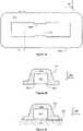
- Figures 3a, 3b, and 3cillustrate a manufacturing process of a detail of an instrument product according to an exemplifying and non-limiting embodiment of the invention.
- FIG. 3a-3cshows a section view where the section plane is parallel with the xy-plane of a coordinate system 399.
- the instrument productcomprises a medical hand instrument 301 a part of which is shown in figures 3a-3c .
- the instrument productcomprises a radio frequency identifier 302.
- a mold element 305is used in the manufacture of the instrument product.
- Figure 3aillustrates a situation where the radio frequency identifier 302 has been placed on a surface of the medical hand instrument 301 and the mold element 315 has been placed to surround the radio frequency identifier 302.
- Figure 3billustrates a situation where adhesive material 303 is injected via an aperture 313 of the mold element 305 into free spaces in the mold element 305.
- Figure 3cillustrates a situation where the adhesive material 303 has cured, i.e. solidified, and the mold element 305 has been removed.
- the shape of a surface 306 of the solidified adhesive material 303is determined by the mold element 305.
- the surface 306 of the solidified adhesive materialconstitutes a part of the outer surface of the instrument product. It is also possible that the mold element 305 is not removed and thereby the mold element 305 is an element of the instrument product.
- Figure 3dshow a section view of a detail of an instrument product where the mold element 305' is an element of the instrument product. As illustrated in figure 3d , the mold element 305' is designed so that the adhesive material 303 binds the mold element 305' to be an element of the instrument product.
- FIGs 4a, 4b, and 4cillustrate a manufacturing process of a detail of an instrument product according to an exemplifying and non-limiting embodiment of the invention.
- Each of figures 4a-4cshows a section view where the section plane is parallel with the xy-plane of a coordinate system 499.
- the instrument productcomprises a medical hand instrument 401 a part of which is shown in figure 4c .
- the instrument productcomprises a radio frequency identifier 402.
- a mold element 405is used in the manufacture of the instrument product.
- Figure 4aillustrates a situation where the radio frequency identifier 402 has been placed on the bottom of the mold element 405.
- Figure 4billustrates a situation where free spaces in the mold element 405 have been filled with adhesive material 403.
- Figure 4cillustrates a situation where the mold element 405 containing the adhesive material 403 and the radio frequency identifier 402 has been pressed against the surface of the medical hand instrument 401. As shown in figure 4c , a part of the adhesive material 403 is extruded out from the mold element 405.
- FIGs 5a, 5b, and 5cillustrate a detail of an instrument product according to an exemplifying and non-limiting embodiment of the invention.
- the instrument productcomprises a medical hand instrument 501 a part of which is shown in figure 5c .
- the instrument productcomprises a radio frequency identifier 502.
- the instrument productfurther comprises a cover element 507 made of suitable cover material 504.
- Each of figures 5b and 5cshows a section view where the section plane is parallel with the xy-plane of a coordinate system 599.
- Figure 5ashows a bottom view of the cover element 507.
- the cover element 507comprises a cavity for the radio frequency identifier 502.
- the cover element 507is attached with adhesive material 503 to the surface of the medical hand instrument 501 so that the cavity opens towards the surface of the medical hand instrument 501.
- the cover element 507is advantageously made of flexible material and the cavity is advantageously dimensioned so that the cover element 507 gets stretched in response to insertion of the radio frequency identifier 502 in the cavity.
- the radio frequency identifier 502is held in the cavity by friction force. This facilitates the process for attaching the combination of the cover element 507 and the radio frequency identifier 502 to the surface of the medical hand instrument 501.
- the edge portion of the cavityis provided with one or more claw sections 508 and 509 for shape-locking the radio frequency identifier 502 inside the cavity of the cover element 507.
- the cover material that at least partly covers the radio frequency identifieris advantageously flexible and soft enough to protect the radio frequency identifier against external mechanical impacts. It is advantageous that the cover material and also the adhesive material after curing are flexible because different materials of the instrument product may have different coefficients of thermal expansion and the flexibility reduces mechanical stresses caused by differences in thermal expansions.
- the materials of instrument products according to exemplifying and non-limiting embodiments of the inventionare advantageously selected so that the instrument products are suitable for autoclave sterilization with sufficient temperature and duration and for a sufficient number of sterilization cycles.
- the sterilization temperaturecan be e.g. 134°C or 121°C, and the duration of each sterilization cycle can be e.g. 3-6 minutes or sometimes more.
- An instrument productis advantageously capable of withstanding at least 1000 sterilization cycles of the kind mentioned above.
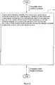
- Figure 6shows a flowchart of a method according to an exemplifying and non-limiting embodiment of the invention for manufacturing an instrument product that comprises a medical hand instrument and a radio frequency identifier readable from a distance away from the radio frequency identifier.
- the methodcomprises at least the following action: action 601: placing the radio frequency identifier on a surface of the medical hand instrument and covering the radio frequency identifier at least partly with cover material so that the cover material gets attached with adhesive material to the surface of the medical hand instrument so that the adhesive material is in contact with both the cover material and the surface of the medical hand instrument, wherein the adhesive material is dispensed in fluidic form and allowed to cure.
- the cover materialis the same material as the adhesive material, and the covering is carried out by dispensing or casting the adhesive material in fluidic form to cover at least partly the radio frequency identifier attached with the adhesive material to the surface of the medical hand instrument.
- a method according to an exemplifying and non-limiting embodiment of the inventioncomprises covering at least 90 % of surface area the radio frequency identifier with the adhesive material.
- a method according to an exemplifying and non-limiting embodiment of the inventioncomprises covering at least 95 % of surface area the radio frequency identifier with the adhesive material.
- a methodcomprises placing a mold element to surround the radio frequency identifier when the radio frequency identifier is on the surface of the medical hand instrument and injecting the adhesive material into the mold element.
- the methodmay further comprise removing the mold element from the instrument product. It is also possible that the mold element is not removed from the instrument product, i.e. the mold element is not only a tool used in the manufacture of the instrument product but also an element of the instrument product.
- a methodcomprises placing the radio frequency identifier and the adhesive material into a mold element, and pressing the mold element containing the adhesive material and the radio frequency identifier against the surface of the medical hand instrument.
- the methodmay further comprise removing the mold element from the instrument product. It is also possible that the mold element is not removed from the instrument product.
- the above-mentioned cover materialconstitutes a cover element comprising a cavity.
- the methodcomprises inserting the radio frequency identifier in the cavity and then attaching the cover element to the surface of the medical hand instrument with the adhesive material so that the cavity opens towards the surface of the medical hand instrument.
- the cavityis dimensioned so that the cover element gets stretched when the radio frequency identifier is inserted in the cavity.
- an edge portion of the cavityis provided with at least one claw section for shape-locking the radio frequency identifier inside the cavity.
- a method according to an exemplifying and non-limiting embodiment of the inventioncomprises positioning the radio frequency identifier so that the distance between the surface of the medical hand instrument and the radio frequency identifier is less than 1 mm, more advantageously less than 0.5 mm, yet more advantageously less than 0.2 mm, and yet more advantageously less than 0.05 mm.
- the above-mentioned surface of the medical hand instrumentis a surface of an elongated element of the medical hand instrument and the radio frequency identifier is placed substantially in the middle area of the elongated element of the medical hand instrument.
- the radio frequency identifierhas an elongated shape and the radio frequency identifier is attached to the medical hand instrument so that the longitudinal direction of the radio frequency identifier is substantially parallel with the longitudinal direction of the above-mentioned elongated element of the medical hand instrument.
- a method according to the inventioncomprises attaching the radio frequency identifier to an end-portion of an elongated element of the medical hand instrument so that the longitudinal directions of the elongated element of the medical hand instrument and the radio frequency identifier are substantially parallel with each other and an end-portion of the radio frequency identifier capable of emitting stronger radiation than the other end-portion of the radio frequency identifier points towards the middle area of the elongated element of the medical hand instrument.
Landscapes
- Health & Medical Sciences (AREA)
- Life Sciences & Earth Sciences (AREA)
- Engineering & Computer Science (AREA)
- Surgery (AREA)
- Oral & Maxillofacial Surgery (AREA)
- Animal Behavior & Ethology (AREA)
- General Health & Medical Sciences (AREA)
- Public Health (AREA)
- Veterinary Medicine (AREA)
- Physics & Mathematics (AREA)
- Pathology (AREA)
- Heart & Thoracic Surgery (AREA)
- Molecular Biology (AREA)
- Medical Informatics (AREA)
- Nuclear Medicine, Radiotherapy & Molecular Imaging (AREA)
- Biomedical Technology (AREA)
- Dentistry (AREA)
- Epidemiology (AREA)
- Electromagnetism (AREA)
- Computer Hardware Design (AREA)
- Microelectronics & Electronic Packaging (AREA)
- General Physics & Mathematics (AREA)
- Theoretical Computer Science (AREA)
- Adhesives Or Adhesive Processes (AREA)
- Lining Or Joining Of Plastics Or The Like (AREA)
- Dental Tools And Instruments Or Auxiliary Dental Instruments (AREA)
Description
- The disclosure relates to an instrument product and to a method for manufacturing the same. The instrument product comprises a medical hand instrument that can be, for example but not necessarily, a dental or surgical instrument.
- In many cases, authorities and actors of the medical and/or dental field want to have an infallible and traceable solution to follow instruments so as be able to trace disinfection, sterilization, reparation, and other operations directed to or carried out with the instruments under consideration. Nowadays, users do not typically have the time and willingness to generate reports manually because of the related workload. In addition, there is a risk of errors with manual data recording and identification of instruments, which prevents regarding the manually recorded data as an irrefutable proof of what has been done and what has been not done.
WO2008062387 describes an instrument comprising a radio frequency identifier "RFID". The radio frequency identifier is embedded in a polymer sheet that is attached on a surface of the handle of the instrument. The polymer sheet that includes the radio frequency identifier can be, for example, wrapped around the handle of the instrument. In order to obtain an even surface, it is possible to provide the instrument with a recess corresponding in size to the polymer sheet. In an advantageous embodiment described inWO2008062387 , the polymer sheet comprises two layers between which the radio frequency identifier is located. The two layers are made of materials having different hardness. The layer of the harder material is against the instrument in order to obtain a better adhesion. The softer material protects the radio frequency identifier against external mechanical impacts. It may be, however, in some circumstances hard to guarantee that the polymer sheet remains firmly attached to the handle of the instrument. Furthermore, in some cases the shape of the handle may deviate from a cylindrical shape so that slits are left between the polymer sheet and the handle when the polymer sheet is wrapped around the handle. The slits are undesirable because, in some circumstances, they may collect impurities. For example, the shape of handles of pliers deviates typically significantly from a cylindrical shape.US2016/296299 discloses an apparatus and a method for attaching an identification tag to a solid surface and protecting the identification tag.- The following presents a simplified summary in order to provide a basic understanding of some aspects of various embodiments of the invention. The summary is not an extensive overview of the invention. It is neither intended to identify key or critical elements of the invention nor to delineate the scope of the invention. The following summary merely presents some concepts of the invention in a simplified form as a prelude to a more detailed description of exemplifying embodiments of the invention.
- In accordance with the invention, there is provided a new instrument product that comprises:
- a medical hand instrument, and
- a radio frequency identifier "RFID" on a surface of the medical hand instrument, the radio frequency identifier being readable from a distance away from the radio frequency identifier,
- the radio frequency identifier has an elongated shape and an end-portion of the radio frequency identifier is capable of emitting stronger radiation than another end-portion of the radio frequency identifier,
- the surface of the medical hand instrument is a surface of an elongated element of the medical hand instrument, and
- the radio frequency identifier is located at an end-portion of the elongated element of the medical hand instrument so that i) longitudinal directions of the elongated element of the medical hand instrument and the radio frequency identifier are substantially parallel with each other and ii) the end portion (210) of the radio frequency identifier capable of emitting stronger radiation points towards a middle area of the medical hand instrument.
- The radio frequency identifier is at least partly covered with cover material attached with adhesive material to the surface of the medical hand instrument so that the adhesive material is in contact with both the cover material and the surface of the medical hand instrument. The cover material can be the same material as the adhesive material and it can be arranged, e.g. cast or dispensed, to cover the radio frequency identifier after the radio frequency identifier has been attached to the surface of the medical hand instrument or simultaneously when the radio frequency identifier is being attached to the surface of the medical hand instrument. Alternatively, the cover material may constitute a cover element which comprises a cavity for the radio frequency identifier and which is attached with the adhesive material to the surface of the medical hand instrument. The adhesive material is dispensable in fluidic form prior to its curing, and thus the adhesive material can adapt with different shapes of the surface of the medical hand instrument. Therefore, slits which may collect impurities in some circumstances can be avoided. The adhesive material can be for example suitable silicone based adhesive or suitable epoxy resin based adhesive.
- The above-mentioned medical hand instrument can be, for example but not necessarily, a dental or surgical hand instrument.
- In accordance with the invention, there is provided also a new method for manufacturing an instrument product that comprises a medical hand instrument and a radio frequency identifier readable from a distance away from the radio frequency identifier.
- The method comprises placing the radio frequency identifier on a surface of the medical hand instrument and covering the radio frequency identifier at least partly with cover material so that the cover material gets attached with adhesive material to the surface of the medical hand instrument so that the adhesive material is in contact with both the cover material and the surface of the medical hand instrument, wherein the adhesive material is dispensed in fluidic form and allowed to cure.
- In the above-mentioned method:
- the radio frequency identifier has an elongated shape and an end-portion of the radio frequency identifier is capable of emitting stronger radiation than another end-portion of the radio frequency identifier,
- the surface of the medical hand instrument is a surface of an elongated element of the medical hand instrument, and
- the radio frequency identifier is placed on an end-portion of the elongated element of the medical hand instrument so that i) longitudinal directions of the elongated element of the medical hand instrument and the radio frequency identifier are substantially parallel with each other and ii) the end-portion of the radio frequency identifier capable of emitting stronger radiation points towards a middle area of the medical hand instrument.
- A number of exemplifying and non-limiting embodiments of the invention are described in accompanied dependent claims.
- Various exemplifying and non-limiting embodiments of the invention both as to constructions and to methods of operation, together with additional objects and advantages thereof, will be best understood from the following description of specific exemplifying and non-limiting embodiments when read in connection with the accompanying drawings.
- The verbs "to comprise" and "to include" are used in this document as open limitations that neither exclude nor require the existence of un-recited features. The features recited in dependent claims are mutually freely combinable unless otherwise explicitly stated. Furthermore, it is to be understood that the use of "a" or "an", i.e. a singular form, throughout this document does not exclude a plurality.
- Exemplifying and non-limiting embodiments of the invention and their advantages are explained in greater detail below in the sense of examples and with reference to the accompanying drawings, in which:
figures 1a and 1b illustrate an instrument product according to an exemplifying and non-limiting embodiment of the invention,figures 2a, 2b, and 2c illustrate an instrument product according to another exemplifying and non-limiting embodiment of the invention,figures 3a, 3b, and 3c illustrate a manufacturing process of a detail of an instrument product according to an exemplifying and non-limiting embodiment of the invention, andfigure 3d illustrates a detail of an instrument product according to an exemplifying and non-limiting embodiment of the inventionfigures 4a, 4b, and 4c illustrate a manufacturing process of a detail of an instrument product according to an exemplifying and non-limiting embodiment of the invention,figures 5a, 5b, and 5c illustrate a detail of an instrument product according to an exemplifying and non-limiting embodiment of the invention, andfigure 6 shows a flowchart of a method according to an exemplifying and non-limiting embodiment of the invention for manufacturing an instrument product.- The specific examples provided in the description below should not be construed as limiting the scope and/or the applicability of the accompanied claims. Lists and groups of examples provided in the description are not exhaustive unless otherwise explicitly stated.
Figure 1a shows a side-view of an instrument product according to an exemplifying and non-limiting embodiment of the invention.Figure 1a shows also a part of a section taken along a line A-A so that the section plane is parallel with the xy-plane of acoordinate system 199.Figure 1b shows a part of the instrument product when seen along the negative y-direction of thecoordinate system 199. The instrument product comprises amedical hand instrument 101 and a radio frequency identifier "RFID" 102 that can be, for example but not necessarily, a ceramic radio frequency identifier tag. Infigure 1b and in the side-view shown infigure 1a , theradio frequency identifier 102 is depicted with dashed lines. Theradio frequency identifier 102 is readable from a distance away from the radio frequency identifier. Theradio frequency identifier 102 may comprise, for example but not necessarily, a memory circuit capable of storing digital information. The digital information may contain for example identifying information identifying themedical hand instrument 101 as an individual object from among similar medical hand instruments and/or information indicating e.g. the date of manufacture of the medical hand instrument, the manufacturer of the medical hand instrument and/or other information related directly or indirectly to the medical hand instrument. Furthermore, the digital information may indicate the number of maintenance and/or sterilization cycles. It is however also possible that theradio frequency identifier 102 does not comprise any memory circuit but identification information related to theradio frequency identifier 102 is represented by e.g. radiation properties of theradio frequency identifier 102. In the exemplifying case illustrated infigures 1a and 1b , themedical hand instrument 101 is a dental instrument suitable for e.g. removing dental calculus. The medical hand instrument comprisesoperative portions 112 for performing the operations according to the purpose of use of the medical hand instrument. Themedical hand instrument 101 further comprises a handle that is mechanically connected to theoperative portions 112 as illustrated infigure 1a .- In the exemplifying instrument product illustrated in
figures 1a and 1b , theradio frequency identifier 102 is covered withadhesive material 103 that attaches to a surface of themedical hand instrument 101. Theadhesive material 103 is such that it is dispensable in fluidic form prior to its curing. Theadhesive material 103 can be for example suitable silicone based adhesive. In many cases, the surface of themedical hand instrument 101 is advantageously pretreated with suitable primer, e.g. silane, in order to provide a better attachment between theadhesive material 103 and themedical hand instrument 101. The above-mentioned surface of themedical hand instrument 101 can be a metal surface or a surface of some other material such as e.g. plastic. As theadhesive material 103 is fluidic prior to its curing, theadhesive material 103 can adapt with different shapes of the surface of themedical hand instrument 101 and thereby slits which may collect impurities in some circumstances can be avoided. In the exemplifyingmedical hand instrument 101, the handle comprises circumferential grooves so as to provide a better grip. Theadhesive material 103 which is fluidic prior to its curing can adapt with the circumferential grooves of the handle. - In the exemplifying instrument product illustrated in
figures 1a and 1b , theradio frequency identifier 102 is fully covered with theadhesive material 103. It is, however, also possible that e.g. the upper surface of the radio frequency identifier is not covered by theadhesive material 103. In an instrument product according an exemplifying and non-limiting embodiment of the invention, at least 90 % of the surface area the radio frequency identifier is covered by the adhesive material. In an instrument product according an exemplifying and non-limiting embodiment of the invention, at least 95 % of the surface area the radio frequency identifier is covered by the adhesive material. - In cases where the handle of the
medical hand instrument 101 is made of metal or comprises metal, themedical hand instrument 101 can act as an external antenna for theradio frequency identifier 102. In order to achieve proper antenna operation, theradio frequency identifier 102 is advantageously positioned so that the distance d between the surface of themedical hand instrument 101 and theradio frequency identifier 102 is less than 1 mm, more advantageously less than 0.5 mm, yet more advantageously less than 0.2 mm, and yet more advantageously less than 0.05 mm. The radio frequency used by theradio frequency identifier 102 is advantageously selected so that the wavelength of the radio waves is compatible with the physical length of themedical hand instrument 101. The wave length of the radio waves can be about e.g. 300 mm. Figure 2a shows side-views of an instrument product according to an exemplifying and non-limiting embodiment of the invention.Figure 2b shows a part of a section taken along a line A-A shown infigure 2a. Figure 2c shows a part of a section taken along a line B-B shown infigure 2a . The section plane related tofigure 2b is parallel with the xy-plane of a coordinatesystem 299, and the section plane related tofigure 2c is parallel with the xz-plane of the coordinatesystem 299. The instrument product comprises amedical hand instrument 201 and a radio frequency identifier "RFID" 202. Infigure 2a , theradio frequency identifier 202 is depicted with dashed lines. The radio frequency identifier "RFID" 102 is readable from a distance away from the radio frequency identifier. Theradio frequency identifier 202 is covered withadhesive material 203 that attaches to a surface of themedical hand instrument 201. In the exemplifying case illustrated infigures 2a-2c , themedical hand instrument 201 is tweezers.- In the exemplifying instrument products illustrated in
figures 1a and 1b and infigures 2a-2c , the radio frequency identifier is located on a surface of an elongated element of the medical hand instrument. In the instrument product illustrated infigures 1a and 1b , the elongated element is the handle of themedical hand instrument 101. In the instrument product illustrated infigures 2a-2c , the elongated element is a metal strip constituting one half of the tweezers. Concerning the operation of the radio frequency identifier, the radio frequency identifier is located advantageously in the middle area of the above-mentioned elongated element as is the case in the instrument product illustrated infigures 1a and 1b . In the instrument product illustrated infigures 2a-2c , theradio frequency identifier 202 is placed on the head of the tweezers because the radio frequency identifier might disturb a user of the tweezers if theradio frequency identifier 202 were placed in the middle of the metal strip constituting the one half of the tweezers. - In the exemplifying instrument products illustrated in
figures 1a and 1b and infigures 2a-2c , the radio frequency identifier has an elongated shape and the longitudinal direction of the radio frequency identifier is substantially parallel with the longitudinal direction of the above-mentioned elongated element of the medical hand instrument. In the exemplifying instrument product illustrated infigures 2a-2c , theradio frequency identifier 202 is positioned so that an end-portion 210 of theradio frequency identifier 202 that is capable of emitting stronger radiation than the other end-portion 211 of theradio frequency identifier 202 points towards the middle area of themedical hand instrument 201. This arrangement improves the operation of theradio frequency identifier 202 in this instrument product where theradio frequency identifier 202 is on the head of the tweezers, i.e. not in the middle area of the metal strip constituting the one half of the tweezers. Figures 3a, 3b, and 3c illustrate a manufacturing process of a detail of an instrument product according to an exemplifying and non-limiting embodiment of the invention.- Each of
figures 3a-3c shows a section view where the section plane is parallel with the xy-plane of a coordinatesystem 399. The instrument product comprises a medical hand instrument 301 a part of which is shown infigures 3a-3c . Furthermore, the instrument product comprises aradio frequency identifier 302. In this exemplifying case, amold element 305 is used in the manufacture of the instrument product.Figure 3a illustrates a situation where theradio frequency identifier 302 has been placed on a surface of themedical hand instrument 301 and the mold element 315 has been placed to surround theradio frequency identifier 302.Figure 3b illustrates a situation whereadhesive material 303 is injected via anaperture 313 of themold element 305 into free spaces in themold element 305.Figure 3c illustrates a situation where theadhesive material 303 has cured, i.e. solidified, and themold element 305 has been removed. In this exemplifying case, the shape of asurface 306 of the solidifiedadhesive material 303 is determined by themold element 305. As themold element 305 is removed, thesurface 306 of the solidified adhesive material constitutes a part of the outer surface of the instrument product. It is also possible that themold element 305 is not removed and thereby themold element 305 is an element of the instrument product.Figure 3d show a section view of a detail of an instrument product where the mold element 305' is an element of the instrument product. As illustrated infigure 3d , the mold element 305' is designed so that theadhesive material 303 binds the mold element 305' to be an element of the instrument product. Figures 4a, 4b, and 4c illustrate a manufacturing process of a detail of an instrument product according to an exemplifying and non-limiting embodiment of the invention. Each offigures 4a-4c shows a section view where the section plane is parallel with the xy-plane of a coordinatesystem 499. The instrument product comprises a medical hand instrument 401 a part of which is shown infigure 4c . Furthermore, the instrument product comprises aradio frequency identifier 402. In this exemplifying case, amold element 405 is used in the manufacture of the instrument product.Figure 4a illustrates a situation where theradio frequency identifier 402 has been placed on the bottom of themold element 405.Figure 4b illustrates a situation where free spaces in themold element 405 have been filled withadhesive material 403.Figure 4c illustrates a situation where themold element 405 containing theadhesive material 403 and theradio frequency identifier 402 has been pressed against the surface of themedical hand instrument 401. As shown infigure 4c , a part of theadhesive material 403 is extruded out from themold element 405.Figures 5a, 5b, and 5c illustrate a detail of an instrument product according to an exemplifying and non-limiting embodiment of the invention. The instrument product comprises a medical hand instrument 501 a part of which is shown infigure 5c . The instrument product comprises aradio frequency identifier 502. In this exemplifying case, the instrument product further comprises acover element 507 made ofsuitable cover material 504. Each offigures 5b and 5c shows a section view where the section plane is parallel with the xy-plane of a coordinate system 599.Figure 5a shows a bottom view of thecover element 507. Thecover element 507 comprises a cavity for theradio frequency identifier 502. As illustrated infigure 5c , thecover element 507 is attached withadhesive material 503 to the surface of themedical hand instrument 501 so that the cavity opens towards the surface of themedical hand instrument 501. Thecover element 507 is advantageously made of flexible material and the cavity is advantageously dimensioned so that thecover element 507 gets stretched in response to insertion of theradio frequency identifier 502 in the cavity. Thus, theradio frequency identifier 502 is held in the cavity by friction force. This facilitates the process for attaching the combination of thecover element 507 and theradio frequency identifier 502 to the surface of themedical hand instrument 501. It is also possible that the edge portion of the cavity is provided with one ormore claw sections radio frequency identifier 502 inside the cavity of thecover element 507.- In instrument products according to exemplifying and non-limiting embodiments of the invention, the cover material that at least partly covers the radio frequency identifier is advantageously flexible and soft enough to protect the radio frequency identifier against external mechanical impacts. It is advantageous that the cover material and also the adhesive material after curing are flexible because different materials of the instrument product may have different coefficients of thermal expansion and the flexibility reduces mechanical stresses caused by differences in thermal expansions.
- The materials of instrument products according to exemplifying and non-limiting embodiments of the invention are advantageously selected so that the instrument products are suitable for autoclave sterilization with sufficient temperature and duration and for a sufficient number of sterilization cycles. The sterilization temperature can be e.g. 134°C or 121°C, and the duration of each sterilization cycle can be e.g. 3-6 minutes or sometimes more. An instrument product is advantageously capable of withstanding at least 1000 sterilization cycles of the kind mentioned above.
Figure 6 shows a flowchart of a method according to an exemplifying and non-limiting embodiment of the invention for manufacturing an instrument product that comprises a medical hand instrument and a radio frequency identifier readable from a distance away from the radio frequency identifier. The method comprises at least the following action:
action 601: placing the radio frequency identifier on a surface of the medical hand instrument and covering the radio frequency identifier at least partly with cover material so that the cover material gets attached with adhesive material to the surface of the medical hand instrument so that the adhesive material is in contact with both the cover material and the surface of the medical hand instrument, wherein the adhesive material is dispensed in fluidic form and allowed to cure.- In a method according to an exemplifying and non-limiting embodiment of the invention, the cover material is the same material as the adhesive material, and the covering is carried out by dispensing or casting the adhesive material in fluidic form to cover at least partly the radio frequency identifier attached with the adhesive material to the surface of the medical hand instrument.
- A method according to an exemplifying and non-limiting embodiment of the invention comprises covering at least 90 % of surface area the radio frequency identifier with the adhesive material.
- A method according to an exemplifying and non-limiting embodiment of the invention comprises covering at least 95 % of surface area the radio frequency identifier with the adhesive material.
- A method according to an exemplifying and non-limiting embodiment of the invention comprises placing a mold element to surround the radio frequency identifier when the radio frequency identifier is on the surface of the medical hand instrument and injecting the adhesive material into the mold element. The method may further comprise removing the mold element from the instrument product. It is also possible that the mold element is not removed from the instrument product, i.e. the mold element is not only a tool used in the manufacture of the instrument product but also an element of the instrument product.
- A method according to an exemplifying and non-limiting embodiment of the invention comprises placing the radio frequency identifier and the adhesive material into a mold element, and pressing the mold element containing the adhesive material and the radio frequency identifier against the surface of the medical hand instrument. The method may further comprise removing the mold element from the instrument product. It is also possible that the mold element is not removed from the instrument product.
- In a method according to an exemplifying and non-limiting embodiment of the invention, the above-mentioned cover material constitutes a cover element comprising a cavity. In this exemplifying case, the method comprises inserting the radio frequency identifier in the cavity and then attaching the cover element to the surface of the medical hand instrument with the adhesive material so that the cavity opens towards the surface of the medical hand instrument. In a method according to an exemplifying and non-limiting embodiment of the invention, the cavity is dimensioned so that the cover element gets stretched when the radio frequency identifier is inserted in the cavity. In a method according to an exemplifying and non-limiting embodiment of the invention, an edge portion of the cavity is provided with at least one claw section for shape-locking the radio frequency identifier inside the cavity.
- A method according to an exemplifying and non-limiting embodiment of the invention comprises positioning the radio frequency identifier so that the distance between the surface of the medical hand instrument and the radio frequency identifier is less than 1 mm, more advantageously less than 0.5 mm, yet more advantageously less than 0.2 mm, and yet more advantageously less than 0.05 mm. In a method according to an exemplifying and non-limiting embodiment of the invention, the above-mentioned surface of the medical hand instrument is a surface of an elongated element of the medical hand instrument and the radio frequency identifier is placed substantially in the middle area of the elongated element of the medical hand instrument.
- In a method according to the invention, the radio frequency identifier has an elongated shape and the radio frequency identifier is attached to the medical hand instrument so that the longitudinal direction of the radio frequency identifier is substantially parallel with the longitudinal direction of the above-mentioned elongated element of the medical hand instrument.
- A method according to the invention comprises attaching the radio frequency identifier to an end-portion of an elongated element of the medical hand instrument so that the longitudinal directions of the elongated element of the medical hand instrument and the radio frequency identifier are substantially parallel with each other and an end-portion of the radio frequency identifier capable of emitting stronger radiation than the other end-portion of the radio frequency identifier points towards the middle area of the elongated element of the medical hand instrument.
- The specific examples provided in the description given above should not be construed as limiting the scope and/or the applicability of the appended claims. Lists and groups of examples provided in the description given above are not exhaustive unless otherwise explicitly stated.
Claims (19)
- An instrument product comprising:- a medical hand instrument (201, 301, 401, 501), and- a radio frequency identifier (202, 302, 402, 502) on a surface of the medical hand instrument, the radio frequency identifier being readable from a distance away from the radio frequency identifier,wherein the radio frequency identifier is at least partly covered with cover material (203, 303, 403, 504) attached with adhesive material (203, 303, 403, 503) to the surface of the medical hand instrument so that the adhesive material is in contact with both the cover material and the surface of the medical hand instrument, the adhesive material being dispensable in fluidic form prior to curing,characterized in that:- the radio frequency identifier (202) has an elongated shape and an end-portion (210) of the radio frequency identifier is capable of emitting stronger radiation than another end-portion (211) of the radio frequency identifier,- the surface of the medical hand instrument (201) is a surface of an elongated element of the medical hand instrument, and- the radio frequency identifier is located at an end-portion of the elongated element of the medical hand instrument so that i) longitudinal directions of the elongated element of the medical hand instrument and the radio frequency identifier are substantially parallel with each other and ii) the end-portion (210) of the radio frequency identifier capable of emitting stronger radiation points towards a middle area of the medical hand instrument.
- An instrument product according to claim 1, wherein the cover material (203, 303, 403) is same material as the adhesive material (203, 303, 403).
- An instrument product according to claim 2, wherein at least 90 % of the surface area of the radio frequency identifier is covered by the adhesive material.
- An instrument product according to claim 2, wherein at least 95 % of the surface area of the radio frequency identifier is covered by the adhesive material.
- An instrument product according to any of claims 2-4, wherein a shape of a surface (306) of a portion the adhesive material (303) covering the radio frequency identifier is at least partly determined by a mold element, and the instrument product comprises the mold element (405).
- An instrument product according to claim 1, wherein the cover material (504) constitutes a cover element (507) comprising a cavity, the radio frequency identifier (502) being located in the cavity and the cover element being attached with the adhesive material (503) to the surface of the medical hand instrument so that the cavity opens towards the surface of the medical hand instrument.
- An instrument product according to claim 6, wherein the cavity is dimensioned so that the cover element (507) gets stretched in response to insertion of the radio frequency identifier in the cavity.
- An instrument product according to claim 6 or 7, wherein an edge portion of the cavity is provided with at least one claw section (508, 509) for shape-locking the radio frequency identifier inside the cavity.
- An instrument product according to any of claims 1-8, wherein a distance (d) between the surface of the medical hand instrument and the radio frequency identifier is less than 1 mm.
- An instrument product according to any of claims 1-9, wherein the radio frequency identifier is a ceramic radio frequency identifier tag.
- An instrument product according to any of claims 1-10, wherein the surface of the medical hand instrument is a metal surface.
- An instrument product according to any of claims 1-11, wherein the surface of the medical hand instrument (101) is a surface of an elongated element of the medical hand instrument (101), and the radio frequency identifier (102) is located substantially in a middle area of the elongated element of the medical hand instrument.
- An instrument product according to claim 12, wherein the radio frequency identifier (102, 202) has an elongated shape and a longitudinal direction of the radio frequency identifier is substantially parallel with a longitudinal direction of the elongated element of the medical hand instrument.
- An instrument product according to any of claims 1-11, wherein the surface of the medical hand instrument (201) is a surface of an elongated element of the medical hand instrument, the radio frequency identifier (202) has an elongated shape, the radio frequency identifier is located at an end-portion of the elongated element of the medical hand instrument so that longitudinal directions of the elongated element of the medical hand instrument and the radio frequency identifier are substantially parallel with each other and an end-portion (210) of the radio frequency identifier capable of emitting stronger radiation than another end-portion (211) of the radio frequency identifier points towards a middle area of the medical hand instrument.
- A method for manufacturing an instrument product that comprises a medical hand instrument and a radio frequency identifier readable from a distance away from the radio frequency identifier, the method comprising:- placing (601) the radio frequency identifier on a surface of the medical hand instrument, and- covering (601) the radio frequency identifier at least partly with cover material so that the cover material gets attached with adhesive material to the surface of the medical hand instrument so that the adhesive material is in contact with both the cover material and the surface of the medical hand instrument, wherein the adhesive material is dispensed in fluidic form and allowed to cure,characterized in that:- the radio frequency identifier has an elongated shape and an end-portion of the radio frequency identifier is capable of emitting stronger radiation than another end-portion of the radio frequency identifier,- the surface of the medical hand instrument is a surface of an elongated element of the medical hand instrument, and- the radio frequency identifier is placed on an end-portion of the elongated element of the medical hand instrument so that i) longitudinal directions of the elongated element of the medical hand instrument and the radio frequency identifier are substantially parallel with each other and ii) the end-portion of the radio frequency identifier capable of emitting stronger radiation points towards a middle area of the medical hand instrument.
- A method according to claim 15, wherein the cover material is same material as the adhesive material, and the covering is carried out by dispensing or casting the adhesive material in fluidic form to cover at least partly the radio frequency identifier.
- A method according to claim 16, wherein the method comprises placing a mold element to surround the radio frequency identifier when the radio frequency identifier is on the surface of the medical hand instrument, and injecting the adhesive material into the mold element.
- A method according to claim 16, wherein the method comprises placing the radio frequency identifier and the adhesive material into a mold element, and pressing the mold element containing the adhesive material and the radio frequency identifier against the surface of the medical hand instrument.
- A method according to claim 17 or 18, wherein the method comprises removing the mold element from the medical hand instrument.
Applications Claiming Priority (2)
| Application Number | Priority Date | Filing Date | Title |
|---|---|---|---|
| FI20175234AFI128309B (en) | 2017-03-16 | 2017-03-16 | An instrument product and a method for manufacturing the same |
| PCT/FI2018/050196WO2018167373A1 (en) | 2017-03-16 | 2018-03-16 | An instrument product and a method for manufacturing the same |
Publications (3)
| Publication Number | Publication Date |
|---|---|
| EP3595569A1 EP3595569A1 (en) | 2020-01-22 |
| EP3595569A4 EP3595569A4 (en) | 2021-01-06 |
| EP3595569B1true EP3595569B1 (en) | 2022-05-04 |
Family
ID=63521811
Family Applications (1)
| Application Number | Title | Priority Date | Filing Date |
|---|---|---|---|
| EP18767962.6AActiveEP3595569B1 (en) | 2017-03-16 | 2018-03-16 | An instrument product and a method for manufacturing the same |
Country Status (6)
| Country | Link |
|---|---|
| US (1) | US11826211B2 (en) |
| EP (1) | EP3595569B1 (en) |
| DK (1) | DK3595569T3 (en) |
| ES (1) | ES2922459T3 (en) |
| FI (1) | FI128309B (en) |
| WO (1) | WO2018167373A1 (en) |
Families Citing this family (4)
| Publication number | Priority date | Publication date | Assignee | Title |
|---|---|---|---|---|
| EP3669814B1 (en)* | 2018-12-20 | 2020-10-21 | W & H Dentalwerk Bürmoos GmbH | Medical or dental instrument with a rfid storage label |
| US11281952B2 (en)* | 2019-06-04 | 2022-03-22 | Trovan, Ltd. | Systems and methods to secure transponders within RFID tags without potting elements |
| CN112966802A (en)* | 2021-03-12 | 2021-06-15 | 四川大学华西医院 | Medical instrument based on radio frequency identification and medical instrument identification system |
| TWM643640U (en) | 2022-09-29 | 2023-07-11 | 永豐泰科技企業有限公司 | Electronic identification tape for operating room instrument |
Family Cites Families (9)
| Publication number | Priority date | Publication date | Assignee | Title |
|---|---|---|---|---|
| WO2007066204A2 (en)* | 2005-12-06 | 2007-06-14 | Gillispie, William | Apparatus and method for adapting a conductive object to accept a communication device |
| WO2008062387A2 (en) | 2006-11-24 | 2008-05-29 | Satyatek Sa | Marker and marking system for objects |
| DE112010004314A5 (en)* | 2009-11-06 | 2013-02-07 | Viktor Hegedüs | Method for attaching marking elements to an object; Object with a marking element and use of a special material for attaching a marking element to an object |
| US20110139877A1 (en)* | 2009-12-14 | 2011-06-16 | Szakelyhidi David C | Radio Frequency Identification Tag for Use on Metal Objects |
| US9592101B2 (en)* | 2012-09-24 | 2017-03-14 | Satyatek Sa | Radio frequency identification capsule (RFID) |
| MX2016007696A (en)* | 2013-12-11 | 2016-12-09 | Caretag Surgical Aps | Attachment and cover for an electronic identification tag. |
| WO2016086168A1 (en)* | 2014-11-26 | 2016-06-02 | President And Fellows Of Harvard College | Deposition of rfid tags |
| EP3283000A1 (en)* | 2015-04-17 | 2018-02-21 | Caretag Surgical ApS | Attachment of an identification tag |
| CN106691519A (en)* | 2015-11-13 | 2017-05-24 | 刘智佳 | Surgical instrument and mounting method of RFID (radio frequency identification) tag for same |
- 2017
- 2017-03-16FIFI20175234Apatent/FI128309B/enactiveIP Right Grant
- 2018
- 2018-03-16EPEP18767962.6Apatent/EP3595569B1/enactiveActive
- 2018-03-16USUS16/494,354patent/US11826211B2/enactiveActive
- 2018-03-16DKDK18767962.6Tpatent/DK3595569T3/enactive
- 2018-03-16WOPCT/FI2018/050196patent/WO2018167373A1/ennot_activeCeased
- 2018-03-16ESES18767962Tpatent/ES2922459T3/enactiveActive
Also Published As
| Publication number | Publication date |
|---|---|
| FI128309B (en) | 2020-03-13 |
| US11826211B2 (en) | 2023-11-28 |
| ES2922459T3 (en) | 2022-09-15 |
| FI20175234A (en) | 2018-09-17 |
| FI20175234A7 (en) | 2018-09-17 |
| DK3595569T3 (en) | 2022-08-08 |
| EP3595569A4 (en) | 2021-01-06 |
| EP3595569A1 (en) | 2020-01-22 |
| US20200129267A1 (en) | 2020-04-30 |
| WO2018167373A1 (en) | 2018-09-20 |
Similar Documents
| Publication | Publication Date | Title |
|---|---|---|
| EP3595569B1 (en) | An instrument product and a method for manufacturing the same | |
| EP3417826B1 (en) | A dental instrument and a method for manufacturing the same | |
| EP3079624B1 (en) | Attachment and cover for an electronic identification tag | |
| US12059843B2 (en) | Arrangement and method for manufacturing a plurality of orthodontic appliances | |
| CN103068222A (en) | Device for identifying animals and corresponding preparation device | |
| EP3651814B1 (en) | An instrument cassette for handling instruments | |
| US20140092536A1 (en) | Case utilizing reinforced film for in-mold labeling | |
| JP7341226B2 (en) | Dental or surgical handpiece with RFID transponder | |
| CN108027895B (en) | Method of manufacturing RFID tag assembly and RFID tag assembly | |
| CN111051027B (en) | Device for inserting a transponder | |
| KR102810724B1 (en) | Support for preserving samples of biological material and method for preparing the same | |
| HK40024445B (en) | Device for inserting transponder | |
| HK40024445A (en) | Device for inserting transponder |
Legal Events
| Date | Code | Title | Description |
|---|---|---|---|
| STAA | Information on the status of an ep patent application or granted ep patent | Free format text:STATUS: THE INTERNATIONAL PUBLICATION HAS BEEN MADE | |
| PUAI | Public reference made under article 153(3) epc to a published international application that has entered the european phase | Free format text:ORIGINAL CODE: 0009012 | |
| STAA | Information on the status of an ep patent application or granted ep patent | Free format text:STATUS: REQUEST FOR EXAMINATION WAS MADE | |
| 17P | Request for examination filed | Effective date:20190924 | |
| AK | Designated contracting states | Kind code of ref document:A1 Designated state(s):AL AT BE BG CH CY CZ DE DK EE ES FI FR GB GR HR HU IE IS IT LI LT LU LV MC MK MT NL NO PL PT RO RS SE SI SK SM TR | |
| AX | Request for extension of the european patent | Extension state:BA ME | |
| DAV | Request for validation of the european patent (deleted) | ||
| DAX | Request for extension of the european patent (deleted) | ||
| A4 | Supplementary search report drawn up and despatched | Effective date:20201203 | |
| RIC1 | Information provided on ipc code assigned before grant | Ipc:A61B 90/98 20160101AFI20201127BHEP Ipc:A61B 90/90 20160101ALI20201127BHEP Ipc:A61C 3/00 20060101ALI20201127BHEP Ipc:G06K 7/10 20060101ALI20201127BHEP | |
| GRAP | Despatch of communication of intention to grant a patent | Free format text:ORIGINAL CODE: EPIDOSNIGR1 | |
| STAA | Information on the status of an ep patent application or granted ep patent | Free format text:STATUS: GRANT OF PATENT IS INTENDED | |
| INTG | Intention to grant announced | Effective date:20211220 | |
| GRAS | Grant fee paid | Free format text:ORIGINAL CODE: EPIDOSNIGR3 | |
| GRAA | (expected) grant | Free format text:ORIGINAL CODE: 0009210 | |
| STAA | Information on the status of an ep patent application or granted ep patent | Free format text:STATUS: THE PATENT HAS BEEN GRANTED | |
| AK | Designated contracting states | Kind code of ref document:B1 Designated state(s):AL AT BE BG CH CY CZ DE DK EE ES FI FR GB GR HR HU IE IS IT LI LT LU LV MC MK MT NL NO PL PT RO RS SE SI SK SM TR | |
| REG | Reference to a national code | Ref country code:GB Ref legal event code:FG4D | |
| REG | Reference to a national code | Ref country code:CH Ref legal event code:EP | |
| REG | Reference to a national code | Ref country code:AT Ref legal event code:REF Ref document number:1488211 Country of ref document:AT Kind code of ref document:T Effective date:20220515 | |
| REG | Reference to a national code | Ref country code:DE Ref legal event code:R096 Ref document number:602018034999 Country of ref document:DE | |
| REG | Reference to a national code | Ref country code:IE Ref legal event code:FG4D | |
| REG | Reference to a national code | Ref country code:DK Ref legal event code:T3 Effective date:20220804 | |
| REG | Reference to a national code | Ref country code:SE Ref legal event code:TRGR | |
| REG | Reference to a national code | Ref country code:LT Ref legal event code:MG9D | |
| REG | Reference to a national code | Ref country code:NL Ref legal event code:MP Effective date:20220504 | |
| REG | Reference to a national code | Ref country code:ES Ref legal event code:FG2A Ref document number:2922459 Country of ref document:ES Kind code of ref document:T3 Effective date:20220915 | |
| REG | Reference to a national code | Ref country code:AT Ref legal event code:MK05 Ref document number:1488211 Country of ref document:AT Kind code of ref document:T Effective date:20220504 | |
| PG25 | Lapsed in a contracting state [announced via postgrant information from national office to epo] | Ref country code:PT Free format text:LAPSE BECAUSE OF FAILURE TO SUBMIT A TRANSLATION OF THE DESCRIPTION OR TO PAY THE FEE WITHIN THE PRESCRIBED TIME-LIMIT Effective date:20220905 Ref country code:NO Free format text:LAPSE BECAUSE OF FAILURE TO SUBMIT A TRANSLATION OF THE DESCRIPTION OR TO PAY THE FEE WITHIN THE PRESCRIBED TIME-LIMIT Effective date:20220804 Ref country code:NL Free format text:LAPSE BECAUSE OF FAILURE TO SUBMIT A TRANSLATION OF THE DESCRIPTION OR TO PAY THE FEE WITHIN THE PRESCRIBED TIME-LIMIT Effective date:20220504 Ref country code:LT Free format text:LAPSE BECAUSE OF FAILURE TO SUBMIT A TRANSLATION OF THE DESCRIPTION OR TO PAY THE FEE WITHIN THE PRESCRIBED TIME-LIMIT Effective date:20220504 Ref country code:HR Free format text:LAPSE BECAUSE OF FAILURE TO SUBMIT A TRANSLATION OF THE DESCRIPTION OR TO PAY THE FEE WITHIN THE PRESCRIBED TIME-LIMIT Effective date:20220504 Ref country code:GR Free format text:LAPSE BECAUSE OF FAILURE TO SUBMIT A TRANSLATION OF THE DESCRIPTION OR TO PAY THE FEE WITHIN THE PRESCRIBED TIME-LIMIT Effective date:20220805 Ref country code:FI Free format text:LAPSE BECAUSE OF FAILURE TO SUBMIT A TRANSLATION OF THE DESCRIPTION OR TO PAY THE FEE WITHIN THE PRESCRIBED TIME-LIMIT Effective date:20220504 Ref country code:BG Free format text:LAPSE BECAUSE OF FAILURE TO SUBMIT A TRANSLATION OF THE DESCRIPTION OR TO PAY THE FEE WITHIN THE PRESCRIBED TIME-LIMIT Effective date:20220804 Ref country code:AT Free format text:LAPSE BECAUSE OF FAILURE TO SUBMIT A TRANSLATION OF THE DESCRIPTION OR TO PAY THE FEE WITHIN THE PRESCRIBED TIME-LIMIT Effective date:20220504 | |
| PG25 | Lapsed in a contracting state [announced via postgrant information from national office to epo] | Ref country code:RS Free format text:LAPSE BECAUSE OF FAILURE TO SUBMIT A TRANSLATION OF THE DESCRIPTION OR TO PAY THE FEE WITHIN THE PRESCRIBED TIME-LIMIT Effective date:20220504 Ref country code:PL Free format text:LAPSE BECAUSE OF FAILURE TO SUBMIT A TRANSLATION OF THE DESCRIPTION OR TO PAY THE FEE WITHIN THE PRESCRIBED TIME-LIMIT Effective date:20220504 Ref country code:LV Free format text:LAPSE BECAUSE OF FAILURE TO SUBMIT A TRANSLATION OF THE DESCRIPTION OR TO PAY THE FEE WITHIN THE PRESCRIBED TIME-LIMIT Effective date:20220504 Ref country code:IS Free format text:LAPSE BECAUSE OF FAILURE TO SUBMIT A TRANSLATION OF THE DESCRIPTION OR TO PAY THE FEE WITHIN THE PRESCRIBED TIME-LIMIT Effective date:20220904 | |
| PG25 | Lapsed in a contracting state [announced via postgrant information from national office to epo] | Ref country code:SM Free format text:LAPSE BECAUSE OF FAILURE TO SUBMIT A TRANSLATION OF THE DESCRIPTION OR TO PAY THE FEE WITHIN THE PRESCRIBED TIME-LIMIT Effective date:20220504 Ref country code:SK Free format text:LAPSE BECAUSE OF FAILURE TO SUBMIT A TRANSLATION OF THE DESCRIPTION OR TO PAY THE FEE WITHIN THE PRESCRIBED TIME-LIMIT Effective date:20220504 Ref country code:RO Free format text:LAPSE BECAUSE OF FAILURE TO SUBMIT A TRANSLATION OF THE DESCRIPTION OR TO PAY THE FEE WITHIN THE PRESCRIBED TIME-LIMIT Effective date:20220504 Ref country code:EE Free format text:LAPSE BECAUSE OF FAILURE TO SUBMIT A TRANSLATION OF THE DESCRIPTION OR TO PAY THE FEE WITHIN THE PRESCRIBED TIME-LIMIT Effective date:20220504 Ref country code:CZ Free format text:LAPSE BECAUSE OF FAILURE TO SUBMIT A TRANSLATION OF THE DESCRIPTION OR TO PAY THE FEE WITHIN THE PRESCRIBED TIME-LIMIT Effective date:20220504 | |
| REG | Reference to a national code | Ref country code:DE Ref legal event code:R097 Ref document number:602018034999 Country of ref document:DE | |
| PLBE | No opposition filed within time limit | Free format text:ORIGINAL CODE: 0009261 | |
| STAA | Information on the status of an ep patent application or granted ep patent | Free format text:STATUS: NO OPPOSITION FILED WITHIN TIME LIMIT | |
| PG25 | Lapsed in a contracting state [announced via postgrant information from national office to epo] | Ref country code:AL Free format text:LAPSE BECAUSE OF FAILURE TO SUBMIT A TRANSLATION OF THE DESCRIPTION OR TO PAY THE FEE WITHIN THE PRESCRIBED TIME-LIMIT Effective date:20220504 | |
| 26N | No opposition filed | Effective date:20230207 | |
| PG25 | Lapsed in a contracting state [announced via postgrant information from national office to epo] | Ref country code:SI Free format text:LAPSE BECAUSE OF FAILURE TO SUBMIT A TRANSLATION OF THE DESCRIPTION OR TO PAY THE FEE WITHIN THE PRESCRIBED TIME-LIMIT Effective date:20220504 | |
| PG25 | Lapsed in a contracting state [announced via postgrant information from national office to epo] | Ref country code:MC Free format text:LAPSE BECAUSE OF FAILURE TO SUBMIT A TRANSLATION OF THE DESCRIPTION OR TO PAY THE FEE WITHIN THE PRESCRIBED TIME-LIMIT Effective date:20220504 | |
| REG | Reference to a national code | Ref country code:BE Ref legal event code:MM Effective date:20230331 | |
| PG25 | Lapsed in a contracting state [announced via postgrant information from national office to epo] | Ref country code:LU Free format text:LAPSE BECAUSE OF NON-PAYMENT OF DUE FEES Effective date:20230316 | |
| REG | Reference to a national code | Ref country code:IE Ref legal event code:MM4A | |
| PG25 | Lapsed in a contracting state [announced via postgrant information from national office to epo] | Ref country code:IE Free format text:LAPSE BECAUSE OF NON-PAYMENT OF DUE FEES Effective date:20230316 | |
| PG25 | Lapsed in a contracting state [announced via postgrant information from national office to epo] | Ref country code:BE Free format text:LAPSE BECAUSE OF NON-PAYMENT OF DUE FEES Effective date:20230331 | |
| PG25 | Lapsed in a contracting state [announced via postgrant information from national office to epo] | Ref country code:BG Free format text:LAPSE BECAUSE OF FAILURE TO SUBMIT A TRANSLATION OF THE DESCRIPTION OR TO PAY THE FEE WITHIN THE PRESCRIBED TIME-LIMIT Effective date:20220504 | |
| PG25 | Lapsed in a contracting state [announced via postgrant information from national office to epo] | Ref country code:BG Free format text:LAPSE BECAUSE OF FAILURE TO SUBMIT A TRANSLATION OF THE DESCRIPTION OR TO PAY THE FEE WITHIN THE PRESCRIBED TIME-LIMIT Effective date:20220504 | |
| PGFP | Annual fee paid to national office [announced via postgrant information from national office to epo] | Ref country code:DE Payment date:20250218 Year of fee payment:8 | |
| PGFP | Annual fee paid to national office [announced via postgrant information from national office to epo] | Ref country code:DK Payment date:20250218 Year of fee payment:8 | |
| PGFP | Annual fee paid to national office [announced via postgrant information from national office to epo] | Ref country code:SE Payment date:20250218 Year of fee payment:8 | |
| PGFP | Annual fee paid to national office [announced via postgrant information from national office to epo] | Ref country code:FR Payment date:20250218 Year of fee payment:8 | |
| PGFP | Annual fee paid to national office [announced via postgrant information from national office to epo] | Ref country code:IT Payment date:20250218 Year of fee payment:8 Ref country code:GB Payment date:20250221 Year of fee payment:8 | |
| PGFP | Annual fee paid to national office [announced via postgrant information from national office to epo] | Ref country code:ES Payment date:20250401 Year of fee payment:8 | |
| PGFP | Annual fee paid to national office [announced via postgrant information from national office to epo] | Ref country code:CH Payment date:20250401 Year of fee payment:8 | |
| PG25 | Lapsed in a contracting state [announced via postgrant information from national office to epo] | Ref country code:CY Free format text:LAPSE BECAUSE OF FAILURE TO SUBMIT A TRANSLATION OF THE DESCRIPTION OR TO PAY THE FEE WITHIN THE PRESCRIBED TIME-LIMIT; INVALID AB INITIO Effective date:20180316 | |
| PG25 | Lapsed in a contracting state [announced via postgrant information from national office to epo] | Ref country code:HU Free format text:LAPSE BECAUSE OF FAILURE TO SUBMIT A TRANSLATION OF THE DESCRIPTION OR TO PAY THE FEE WITHIN THE PRESCRIBED TIME-LIMIT; INVALID AB INITIO Effective date:20180316 |