EP3594911B1 - Method for preventing security breaches of a passive remote keyless entry system - Google Patents
Method for preventing security breaches of a passive remote keyless entry systemDownload PDFInfo
- Publication number
- EP3594911B1 EP3594911B1EP18183012.6AEP18183012AEP3594911B1EP 3594911 B1EP3594911 B1EP 3594911B1EP 18183012 AEP18183012 AEP 18183012AEP 3594911 B1EP3594911 B1EP 3594911B1
- Authority
- EP
- European Patent Office
- Prior art keywords
- transceiver unit
- unit
- base station
- mobile device
- vehicle
- Prior art date
- Legal status (The legal status is an assumption and is not a legal conclusion. Google has not performed a legal analysis and makes no representation as to the accuracy of the status listed.)
- Active
Links
Images


Classifications
- B—PERFORMING OPERATIONS; TRANSPORTING
- B60—VEHICLES IN GENERAL
- B60R—VEHICLES, VEHICLE FITTINGS, OR VEHICLE PARTS, NOT OTHERWISE PROVIDED FOR
- B60R25/00—Fittings or systems for preventing or indicating unauthorised use or theft of vehicles
- B60R25/20—Means to switch the anti-theft system on or off
- B60R25/2018—Central base unlocks or authorises unlocking
- B—PERFORMING OPERATIONS; TRANSPORTING
- B60—VEHICLES IN GENERAL
- B60R—VEHICLES, VEHICLE FITTINGS, OR VEHICLE PARTS, NOT OTHERWISE PROVIDED FOR
- B60R25/00—Fittings or systems for preventing or indicating unauthorised use or theft of vehicles
- B60R25/20—Means to switch the anti-theft system on or off
- B60R25/24—Means to switch the anti-theft system on or off using electronic identifiers containing a code not memorised by the user
- B60R25/245—Means to switch the anti-theft system on or off using electronic identifiers containing a code not memorised by the user where the antenna reception area plays a role
- G—PHYSICS
- G07—CHECKING-DEVICES
- G07C—TIME OR ATTENDANCE REGISTERS; REGISTERING OR INDICATING THE WORKING OF MACHINES; GENERATING RANDOM NUMBERS; VOTING OR LOTTERY APPARATUS; ARRANGEMENTS, SYSTEMS OR APPARATUS FOR CHECKING NOT PROVIDED FOR ELSEWHERE
- G07C9/00—Individual registration on entry or exit
- G07C9/00174—Electronically operated locks; Circuits therefor; Nonmechanical keys therefor, e.g. passive or active electrical keys or other data carriers without mechanical keys
- G07C9/00309—Electronically operated locks; Circuits therefor; Nonmechanical keys therefor, e.g. passive or active electrical keys or other data carriers without mechanical keys operated with bidirectional data transmission between data carrier and locks
- G—PHYSICS
- G07—CHECKING-DEVICES
- G07C—TIME OR ATTENDANCE REGISTERS; REGISTERING OR INDICATING THE WORKING OF MACHINES; GENERATING RANDOM NUMBERS; VOTING OR LOTTERY APPARATUS; ARRANGEMENTS, SYSTEMS OR APPARATUS FOR CHECKING NOT PROVIDED FOR ELSEWHERE
- G07C9/00—Individual registration on entry or exit
- G07C9/00174—Electronically operated locks; Circuits therefor; Nonmechanical keys therefor, e.g. passive or active electrical keys or other data carriers without mechanical keys
- G07C9/00571—Electronically operated locks; Circuits therefor; Nonmechanical keys therefor, e.g. passive or active electrical keys or other data carriers without mechanical keys operated by interacting with a central unit
- G—PHYSICS
- G07—CHECKING-DEVICES
- G07C—TIME OR ATTENDANCE REGISTERS; REGISTERING OR INDICATING THE WORKING OF MACHINES; GENERATING RANDOM NUMBERS; VOTING OR LOTTERY APPARATUS; ARRANGEMENTS, SYSTEMS OR APPARATUS FOR CHECKING NOT PROVIDED FOR ELSEWHERE
- G07C9/00—Individual registration on entry or exit
- G07C9/00174—Electronically operated locks; Circuits therefor; Nonmechanical keys therefor, e.g. passive or active electrical keys or other data carriers without mechanical keys
- G07C9/00857—Electronically operated locks; Circuits therefor; Nonmechanical keys therefor, e.g. passive or active electrical keys or other data carriers without mechanical keys where the code of the data carrier can be programmed
- H—ELECTRICITY
- H03—ELECTRONIC CIRCUITRY
- H03L—AUTOMATIC CONTROL, STARTING, SYNCHRONISATION OR STABILISATION OF GENERATORS OF ELECTRONIC OSCILLATIONS OR PULSES
- H03L7/00—Automatic control of frequency or phase; Synchronisation
- H03L7/06—Automatic control of frequency or phase; Synchronisation using a reference signal applied to a frequency- or phase-locked loop
- H03L7/08—Details of the phase-locked loop
- H03L7/0805—Details of the phase-locked loop the loop being adapted to provide an additional control signal for use outside the loop
- B—PERFORMING OPERATIONS; TRANSPORTING
- B60—VEHICLES IN GENERAL
- B60R—VEHICLES, VEHICLE FITTINGS, OR VEHICLE PARTS, NOT OTHERWISE PROVIDED FOR
- B60R2325/00—Indexing scheme relating to vehicle anti-theft devices
- B60R2325/10—Communication protocols, communication systems of vehicle anti-theft devices
- B60R2325/108—Encryption
- G—PHYSICS
- G07—CHECKING-DEVICES
- G07C—TIME OR ATTENDANCE REGISTERS; REGISTERING OR INDICATING THE WORKING OF MACHINES; GENERATING RANDOM NUMBERS; VOTING OR LOTTERY APPARATUS; ARRANGEMENTS, SYSTEMS OR APPARATUS FOR CHECKING NOT PROVIDED FOR ELSEWHERE
- G07C9/00—Individual registration on entry or exit
- G07C9/00174—Electronically operated locks; Circuits therefor; Nonmechanical keys therefor, e.g. passive or active electrical keys or other data carriers without mechanical keys
- G07C9/00309—Electronically operated locks; Circuits therefor; Nonmechanical keys therefor, e.g. passive or active electrical keys or other data carriers without mechanical keys operated with bidirectional data transmission between data carrier and locks
- G07C2009/00317—Electronically operated locks; Circuits therefor; Nonmechanical keys therefor, e.g. passive or active electrical keys or other data carriers without mechanical keys operated with bidirectional data transmission between data carrier and locks keyless data carrier having only one limited data transmission range
- G07C2009/00333—Electronically operated locks; Circuits therefor; Nonmechanical keys therefor, e.g. passive or active electrical keys or other data carriers without mechanical keys operated with bidirectional data transmission between data carrier and locks keyless data carrier having only one limited data transmission range and the lock having more than one limited data transmission ranges
- G—PHYSICS
- G07—CHECKING-DEVICES
- G07C—TIME OR ATTENDANCE REGISTERS; REGISTERING OR INDICATING THE WORKING OF MACHINES; GENERATING RANDOM NUMBERS; VOTING OR LOTTERY APPARATUS; ARRANGEMENTS, SYSTEMS OR APPARATUS FOR CHECKING NOT PROVIDED FOR ELSEWHERE
- G07C9/00—Individual registration on entry or exit
- G07C9/00174—Electronically operated locks; Circuits therefor; Nonmechanical keys therefor, e.g. passive or active electrical keys or other data carriers without mechanical keys
- G07C9/00309—Electronically operated locks; Circuits therefor; Nonmechanical keys therefor, e.g. passive or active electrical keys or other data carriers without mechanical keys operated with bidirectional data transmission between data carrier and locks
- G07C2009/00365—Electronically operated locks; Circuits therefor; Nonmechanical keys therefor, e.g. passive or active electrical keys or other data carriers without mechanical keys operated with bidirectional data transmission between data carrier and locks in combination with a wake-up circuit
- G07C2009/0038—Electronically operated locks; Circuits therefor; Nonmechanical keys therefor, e.g. passive or active electrical keys or other data carriers without mechanical keys operated with bidirectional data transmission between data carrier and locks in combination with a wake-up circuit whereby the wake-up circuit is situated in the keyless data carrier
- G—PHYSICS
- G07—CHECKING-DEVICES
- G07C—TIME OR ATTENDANCE REGISTERS; REGISTERING OR INDICATING THE WORKING OF MACHINES; GENERATING RANDOM NUMBERS; VOTING OR LOTTERY APPARATUS; ARRANGEMENTS, SYSTEMS OR APPARATUS FOR CHECKING NOT PROVIDED FOR ELSEWHERE
- G07C9/00—Individual registration on entry or exit
- G07C9/00174—Electronically operated locks; Circuits therefor; Nonmechanical keys therefor, e.g. passive or active electrical keys or other data carriers without mechanical keys
- G07C9/00309—Electronically operated locks; Circuits therefor; Nonmechanical keys therefor, e.g. passive or active electrical keys or other data carriers without mechanical keys operated with bidirectional data transmission between data carrier and locks
- G07C2009/00507—Electronically operated locks; Circuits therefor; Nonmechanical keys therefor, e.g. passive or active electrical keys or other data carriers without mechanical keys operated with bidirectional data transmission between data carrier and locks keyless data carrier having more than one function
- G07C2009/00539—Electronically operated locks; Circuits therefor; Nonmechanical keys therefor, e.g. passive or active electrical keys or other data carriers without mechanical keys operated with bidirectional data transmission between data carrier and locks keyless data carrier having more than one function anti-theft
- G—PHYSICS
- G07—CHECKING-DEVICES
- G07C—TIME OR ATTENDANCE REGISTERS; REGISTERING OR INDICATING THE WORKING OF MACHINES; GENERATING RANDOM NUMBERS; VOTING OR LOTTERY APPARATUS; ARRANGEMENTS, SYSTEMS OR APPARATUS FOR CHECKING NOT PROVIDED FOR ELSEWHERE
- G07C9/00—Individual registration on entry or exit
- G07C9/00174—Electronically operated locks; Circuits therefor; Nonmechanical keys therefor, e.g. passive or active electrical keys or other data carriers without mechanical keys
- G07C9/00309—Electronically operated locks; Circuits therefor; Nonmechanical keys therefor, e.g. passive or active electrical keys or other data carriers without mechanical keys operated with bidirectional data transmission between data carrier and locks
- G07C2009/00555—Electronically operated locks; Circuits therefor; Nonmechanical keys therefor, e.g. passive or active electrical keys or other data carriers without mechanical keys operated with bidirectional data transmission between data carrier and locks comprising means to detect or avoid relay attacks
- G—PHYSICS
- G07—CHECKING-DEVICES
- G07C—TIME OR ATTENDANCE REGISTERS; REGISTERING OR INDICATING THE WORKING OF MACHINES; GENERATING RANDOM NUMBERS; VOTING OR LOTTERY APPARATUS; ARRANGEMENTS, SYSTEMS OR APPARATUS FOR CHECKING NOT PROVIDED FOR ELSEWHERE
- G07C9/00—Individual registration on entry or exit
- G07C9/00174—Electronically operated locks; Circuits therefor; Nonmechanical keys therefor, e.g. passive or active electrical keys or other data carriers without mechanical keys
- G07C9/00857—Electronically operated locks; Circuits therefor; Nonmechanical keys therefor, e.g. passive or active electrical keys or other data carriers without mechanical keys where the code of the data carrier can be programmed
- G07C2009/00865—Electronically operated locks; Circuits therefor; Nonmechanical keys therefor, e.g. passive or active electrical keys or other data carriers without mechanical keys where the code of the data carrier can be programmed remotely by wireless communication
- G—PHYSICS
- G07—CHECKING-DEVICES
- G07C—TIME OR ATTENDANCE REGISTERS; REGISTERING OR INDICATING THE WORKING OF MACHINES; GENERATING RANDOM NUMBERS; VOTING OR LOTTERY APPARATUS; ARRANGEMENTS, SYSTEMS OR APPARATUS FOR CHECKING NOT PROVIDED FOR ELSEWHERE
- G07C2209/00—Indexing scheme relating to groups G07C9/00 - G07C9/38
- G07C2209/60—Indexing scheme relating to groups G07C9/00174 - G07C9/00944
- G07C2209/61—Signal comprising different frequencies, e.g. frequency hopping
- G—PHYSICS
- G07—CHECKING-DEVICES
- G07C—TIME OR ATTENDANCE REGISTERS; REGISTERING OR INDICATING THE WORKING OF MACHINES; GENERATING RANDOM NUMBERS; VOTING OR LOTTERY APPARATUS; ARRANGEMENTS, SYSTEMS OR APPARATUS FOR CHECKING NOT PROVIDED FOR ELSEWHERE
- G07C2209/00—Indexing scheme relating to groups G07C9/00 - G07C9/38
- G07C2209/60—Indexing scheme relating to groups G07C9/00174 - G07C9/00944
- G07C2209/63—Comprising locating means for detecting the position of the data carrier, i.e. within the vehicle or within a certain distance from the vehicle
- G07C2209/64—Comprising locating means for detecting the position of the data carrier, i.e. within the vehicle or within a certain distance from the vehicle using a proximity sensor
Definitions
- the present inventionrelates to a method for preventing security breaches of a passive remote keyless entry system for authorizing access to a vehicle, the passive remote keyless entry system comprising a base station located at the vehicle and a mobile device, in particular a remote key.
- Passive remote keyless entry (RKE) systemsare intended to authorize access to a vehicle upon request by a driver. They can also be enabled to authorize a control of certain operations of the vehicle like starting an engine. Passive RKE systems usually comprise a base station located at the vehicle and a mobile device, in particular a remote key, carried along by the driver. Upon the driver requesting access to the vehicle, for example by pressing door handles of the vehicle, the base station and the mobile device exchange encrypted messages, including a request code issued by the base station and an access code issued by the mobile device. In case of a positive result of the authorization negotiations, access to the vehicle is granted and an access signal is sent to the vehicle.
- RKEPassive remote keyless entry
- the mobile devicehas to be in the vicinity of the base station during an authorization process. This is achieved by a limited range of transceivers used for the exchange of messages between the mobile device and the base station. Consequently, there is a maximum distance between the mobile device and the base station for the authorization to be successful.
- a relay attackthis maximum distance is increased by monitoring and forwarding the exchanged messages between the mobile device and the base station.
- a first thiefbeing located close to the vehicle, requests access to the vehicle, for example by pressing door handles.
- the base stationsends a request code to the mobile device.
- the first thiefmonitors the transmission and forwards the transmission to a second thief, being located close to the driver and the mobile device.
- the second thiefsends the forwarded request code to the mobile device, where an authorization is negotiated.
- the mobile deviceUpon authorizing access to the vehicle, the mobile device sends an acceptance signal to the base station, which is monitored by the second thief and forwarded to the first thief.
- the first thiefsends the forwarded acceptance signal to the base station which in turn grants access to the vehicle.
- a method for preventing security breaches of a passive remote keyless entry system in accordance with the preamble of claim 1is known from US 9 911 259 B1 .
- the objectis satisfied by a method in accordance with claim 1, and in particular by the base station comprising a first processor unit and a first transceiver unit, the first transceiver unit comprising a timing device, the mobile device comprising a second processor unit and a second transceiver unit, wherein an air travel time T of a single message sent back and forth from the base station to the mobile device is measured, and access to the vehicle is granted depending on the measured air travel time T.
- the inventive methodthus solves the aforementioned problem by determining the distance between the mobile device and the base station during an authorization process. If the distance exceeds a certain predetermined limit, access to the vehicle is refused, irrespective of a result of the authorization negotiations between the base station and the mobile device.
- the distance between the mobile device and the base stationis determined by measuring the air travel time T of a single message sent back and forth from the base station to the mobile device. As the message travels with a known velocity, namely the speed of light, the distance between the base station and the mobile device is directly connected to the measured air travel time T. An upper limit in an allowed distance between the base station and the mobile device therefore corresponds to an upper limit of the air travel time T.
- Standard type processorsare too slow to measure the air travel time T directly, as they neither include timing devices fast enough nor are able to achieve the high transmission rates necessary for an accurate determination of the air travel time T.
- High speed processorsDSP, FPGA
- DSPdigital signal processor
- FPGAfield-programmable gate array
- the first processor unit and the first transceiver unittherefore are separate units connected by a data link. Also the second processor unit and the second transceiver unit are separate units connected by a data link.
- the timing deviceis separated from and not part of the first processor unit.
- the processor unitscan be of standard type and have not to be high speed processors. This has the advantageous effect that the measurement of the air travel time T can be made cost-effective.
- the air travel time Tis measured by a timing device comprised in the first transceiver unit.
- the timing devicecan be part of the transmitter, the receiver, the first memory unit or the control unit of the first transceiver unit, or can be a separate unit in the first transceiver unit.
- the first transceiver unit and the second transceiver unitcan be included in the mobile device or the base station as application-specific integrated circuits (ASIC), comprising all components of the respective unit.
- ASICapplication-specific integrated circuits
- the first transceiver unitsends a start signal to the timing device at a time of sending a request message to the second transceiver unit, the first transceiver unit sends a stop signal to the timing device at a time of receiving a return message from the second transceiver unit, wherein the air travel time T is obtained as a time difference between the start signal and the stop signal.
- the start and the stop signalare sent simultaneously with the transmission of the request message and the reception of the return message, respectively. Thereby it is assured that the timing device can measure the air travel time T very accurately.
- the first transceiver unitmeasures preferably the air travel time T with a time resolution equal or better than 500 ps, and more preferably with a time resolution equal or better than 100 ps. With this time resolution air travel times T can be measured very accurately, allowing the determination of distances between the base station and the mobile device as small as about 15 cm and 3 cm, respectively.
- the second transceiver unitfurther comprises a Phase-Locked-Loop oscillator (PLL), wherein the first transceiver unit broadcasts an activation signal to activate the PLL before sending the start signal to the timing device.
- PLLPhase-Locked-Loop oscillator
- the phase-locked loopincreases the frequency of an oscillator by a factor, i.e. it shifts the frequency of the oscillator to higher values. It is therefore possible to use in the second transceiver unit transmitters emitting at lower frequencies, in particular transmitters emitting low frequency (LF) signals.
- LFlow frequency
- a supply unit for the second transceiver unitcan be a simple battery.
- the PLLis deactivated most of the time and is active during a communication between the base station and the mobile device only.
- the PLLis activated by the activation signal sent by the first transceiver unit.
- the activation signalcan be a short unencrypted wake-up message to the PLL.
- the PLLis deactivated once again, for example by an internal sleep message sent by the second transceiver unit to the PLL.
- the PLLcan also be used to synchronize the base station and the mobile device, by synchronizing a phase of an oscillator's clock signal with an external timing signal. The synchronization is done by comparing and adjusting the phase of the external signal to the phase of the clock signal.
- the base stationauthorizes the access to the vehicle by sending an access signal to the vehicle, in case the air travel time T is shorter than a predetermined time limit TL. In this way it will be ensured that access to the vehicle is granted only in case the mobile device is in the vicinity of the base station. Given a maximal allowed distance between the mobile device and the base station during an authorization process, the time limit TL can be chosen accordingly, using the known travel velocity of the signals, messages or codes between the base station and the mobile device.
- the first transceiver unitcomprises a PLL as well. In this way, also the energy consumption of the first transceiver during an authorization process can be reduced.
- the first processor unitgenerates an encrypted request code and the second processor unit generates an encrypted access code.
- the codes being used in an authorization processwill preferably be encrypted and will include security codes. This makes it difficult to duplicate the codes and ensures that the authorization process is secure.
- the request codecan be generated as a request for access to the vehicle has been initiated by the driver, for example by actuation of an actuation device at the vehicle.
- the actuation devicecan for example include optical sensors, proximity sensors or sensors for detecting manual interaction.
- the access codeis available already, as the request for access is initiated by the driver and the request code is generated.
- the second processor unitcan generate the access code immediately after a previous communication of the base station and the mobile device during a previous negotiation of an access to the vehicle.
- the request messageis preferably the encrypted request code.
- the first processor unitcan transfer the request code to the first transceiver unit via a data link, which then can send the request code immediately to the second transceiver unit. In this way a transmission of a separate, in particular unencrypted, request message can be omitted, saving energy during the authorization process and accelerating the communication and negotiation between the base station and the mobile device.
- the first transceiver unitfurther comprises a first memory unit and the second transceiver unit comprises a second memory unit, wherein the encrypted request code and the encrypted access code are stored in the second memory unit.
- the first memory unit and the second memory unitcomprise preferably one or a plurality of registers, allowing a fast access to stored data.
- the second transceiver unitcompares the encrypted request code and the encrypted access code and, in case of a match, sends an acceptance signal to the base station.
- all the decoding and comparison of the request and access codestakes place in the second transceiver unit, i.e. in the mobile device.
- the access codeitself will not be transmitted to any other place and therefore will never leave the mobile device. This eliminates the possibility of an unlawful interception during a transmission and increases the security of the inventive method.
- the acceptance signalis preferably an unencrypted and/or short acknowledgement message.
- the data volume to be transmittedcan be kept at a minimum, which reduces the energy consumption of the second transceiver unit and enhances the life time of its supply unit.
- the acceptance signalcan be encrypted as well, if desired.
- Tis the measured time difference between the start signal and the stop signal
- TC4, TC6 and TC7can be calculated from known sizes of the transmitted messages or codes and known clock frequencies of the first and second transceiver units.
- TC5can be calculated from the known sizes of the compared messages or codes and the known clock frequency of the second transceiver unit.
- DLis a predetermined value and is selected in way to ensure that the mobile device is in the vicinity of the base station for an access to the vehicle to be granted by the base station.
- the access signalcan be short and unencrypted message sent by the first transceiver unit to the vehicle.
- the present inventionalso relates to a passive remote keyless entry system for authorizing access to a vehicle, configured to perform the inventive method, comprising a base station to be located at the vehicle and a mobile device, in particular a remote key, wherein the base station comprises a first processor unit, a first transceiver unit and a data link between the first processor unit and the first transceiver unit, the mobile device comprises a second processor unit, a second transceiver unit and a data link between the second processor unit and the second transceiver unit, the first transceiver unit comprises a transmitter, a receiver, a first memory unit, a control unit and a timing device, and wherein the second transceiver unit comprises a transmitter, a receiver, a second memory unit and a control unit.
- the first processor unit and the first transceiver unitare separate units connected by a data link. Also the second processor unit and the second transceiver unit are separate units connected by a data link.
- the timing deviceis separated from and not part of the first processor unit. The timing device can be part of the transmitter, the receiver, the first memory unit or the control unit of the first transceiver unit, or can be a separate unit in the first transceiver unit.
- the second transceiver unitfurther comprises a Phase-Locked-Loop oscillator (PLL).
- PLLPhase-Locked-Loop oscillator
- frequencies of oscillators of the second transceiver unitare shifted to higher values.
- the PLLcan also enable a synchronization of the base station and the mobile device.
- the timing deviceis a Time to Digital Converter (TDC), in particular with a time resolution equal or better than 500 ps, more preferably equal or better than 100 ps.
- TDCTime to Digital Converter
- the distance D between the base station and the mobile devicecan be measured very accurately, with a resolution of about 15 cm and 3 cm, respectively.
- the maximum allowed distance DL between base station and mobile devicecan be chosen such that only the mobile device being located in the immediate vicinity of the vehicle can lead to an authorized access to the vehicle.
- the transmitter of the second transceiver unitemits low frequency (LF) signals.
- LFlow frequency
- the operation of LF transmitterrequires significantly less energy than the operation of higher frequency transmitters, in particular HF transmitters.
- the LF transmitterstherefore can increase the lifetime of the supply unit of the mobile device, reducing the risk of a power failure, for example caused by a worn-out battery.
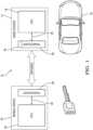
- Fig. 1shows a schematic view of an embodiment of an inventive passive remote keyless entry (RKE) system 12.
- the passive RKE system 12comprises a base station 14 to be located at a vehicle 10 and a mobile device 16, in particular a remote key, which for example can be carried along by a driver (not shown).
- the base station 14comprises a first processor unit 18, a first transceiver unit 20 and a data link 22 between the first processor unit 18 and the first transceiver unit 20.
- the mobile device 16comprises a second processor unit 24, a second transceiver unit 26 and a data link 28 between the second processor unit 24 and the second transceiver unit 26.
- the first transceiver unit 20comprises a transmitter 30, a receiver 32, a first memory unit 34, a control unit 36, a PLL oscillator 38 and a timing device (timer) 40.
- the first memory unit 34is made up by two registers and includes an entry register 34a and an exit register 34b.
- the first transceiver unit 20 and the control unit 36are connected by a control interface 36a.
- Fig. 3shows a schematic view of the second transceiver unit 26 in greater detail.
- the second transceiver unit 26comprises a transmitter 42, a receiver 44, a second memory unit 46, a control unit 48 and a PLL oscillator 50.
- the second memory unit 46is made up by three registers and includes a key register 46a, an entry register 46b and a comparison register 46c.
- the second transceiver unit 26 and the control unit 48are connected by a control interface 48a.
- the first transceiver unit 20 and the second transceiver unit 26can be included in the base station 14 or the mobile device 16 as application-specific integrated circuit (ASIC), comprising all components of the respective transceiver unit 20, 26.
- ASICapplication-specific integrated circuit
- Fig. 4a flowchart of the inventive method for preventing security breaches of a passive RKE system is shown, comprising the steps S1 to S8. All steps of the inventive method, including the steps S1 to S8, are controlled by the control units 36 and 48 of the first and second transceiver units 20 and 26.
- a driverrequests access to the vehicle, for example by actuation of an actuation device (not shown) at the vehicle 10.
- the actuation devicecan include optical sensors, proximity sensors or sensors for detecting manual interaction.
- the request for accesscan be initiated by pressing a dedicated button at the vehicle or by pressing a door handle.
- an encrypted request code 52is generated by the first processor unit 18 and forwarded to the first transceiver unit 20 in step S2.
- the first transceiver unit 20receives the request code 52 via the data link 22 from the first processor unit 18 and stores the code 52 in the entry register 34a of the first memory unit 34.
- the second processor unit 24Similarly to the first processor unit 18, the second processor unit 24 generates an encrypted access code 54 and stores the code 54 in the key register 46a of the second memory unit 46.
- the access code 54can be generated and be available already, as the request for access is initiated by the driver and the request code 52 is generated.
- the second processor unit 24can generate the access code 54 immediately after a previous communication of the base station 14 and the mobile device 16 during a previous negotiation of an access to the vehicle 10.
- the first transceiver unit 20sends an activation signal to the PLL oscillator 50 of the second transceiver unit 26.
- the activation signalcan be a short unencrypted message to wake-up the PLL 50.
- the PLL 50is deactivated most of the time to reduce the energy consumption of the second transceiver unit 26.
- the PLL 50is deactivated once again, for example by an internal sleep message sent by the second transceiver unit 26 to the PLL 50.
- the PLL 50has the effect of increasing the frequency of an oscillator by a factor, shifting the frequencies of an oscillator for example from the low frequency (LF) to the high frequency (HF) range. This is used in the shown embodiment to shift the emitted frequencies of the LF transmitter 42 to the HF range.
- LFlow frequency
- HFhigh frequency
- the PLL 50is also used to synchronize the base station 14 and the mobile device 16. This is done by synchronizing a phase of a clock signal of the second transceiver unit with an external timing signal from the base station 14.
- a PLL 38is also included in the first transceiver unit 20.
- step S4the first transceiver unit 20 sends the request code 52 to the second transceiver unit.
- a time TC4 to finish the transmissionis calculated from a known size of the transmitted request code 52 and a known clock frequency of the first transceiver unit 20.
- the first transceiver unit 20sends a start signal to the timing device 40, which does not form part of the first processor unit 18.
- the timing device 40is for example a Time to Digital Converter (TDC), with a preferred time resolution of e.g. 500 ps, advantageously of equal or better than 100 ps. This time resolution allows measuring a distance D between the base station 14 and the mobile device 16 very accurately, with a resolution of about 15 cm and 3 cm, respectively.
- TDCTime to Digital Converter
- the second transceiver unit 26Upon reception, the second transceiver unit 26 stores in step S5 the request code 52 in an entry register 46b of the second memory unit 46 and compares the request code 52 with the access code 54 in an comparison register 46c of the second memory unit 46.
- a time TC5 to finish the reception and storage of the request code 52 and its comparison with the access code 54is calculated from known sizes of the request code 52 and the access code 54 and the known clock frequency of the second transceiver unit 26.
- an acceptance signal 56is sent from the second transceiver unit 26 to the first transceiver unit 20 in step S6.
- the acceptance signal 56can be an encrypted or an unencrypted message or code, preferably it is an unencrypted short acknowledgment message of known length.
- a time TC6 to finish the transmissionis calculated from a known size of the acceptance signal 56 and the known clock frequency of the second transceiver unit 26.
- the first transceiver unitImmediately after the acceptance signal 56 has been fully received and has been stored in the entry register 34a of the first memory unit 34, the first transceiver unit sends a stop signal to the timing device 40 in step S7.
- a time TC7 to finish the receptionis calculated from the known size of the acceptance signal 56 and the known clock frequency of the first transceiver unit 20.
- step S8an air travel time T is obtained as a time difference between the start signal (see step S4) and the stop signal (see step S7). As the start and the stop signal are sent simultaneously with the transmission of the request code 52 and the reception of the acceptance signal 56, it is assured that the air travel time T is determined very accurately.
- the base station 14In case the distance D between the base station 14 and the mobile device 16 is less than a predetermined maximum allowed distance between the base station 14 and the mobile device 16, the base station 14 authorizes the request for access and sends an access signal to the vehicle 10.
Landscapes
- Engineering & Computer Science (AREA)
- Physics & Mathematics (AREA)
- General Physics & Mathematics (AREA)
- Computer Networks & Wireless Communication (AREA)
- Mechanical Engineering (AREA)
- Mobile Radio Communication Systems (AREA)
- Lock And Its Accessories (AREA)
Description
- The present invention relates to a method for preventing security breaches of a passive remote keyless entry system for authorizing access to a vehicle, the passive remote keyless entry system comprising a base station located at the vehicle and a mobile device, in particular a remote key.
- Passive remote keyless entry (RKE) systems are intended to authorize access to a vehicle upon request by a driver. They can also be enabled to authorize a control of certain operations of the vehicle like starting an engine. Passive RKE systems usually comprise a base station located at the vehicle and a mobile device, in particular a remote key, carried along by the driver. Upon the driver requesting access to the vehicle, for example by pressing door handles of the vehicle, the base station and the mobile device exchange encrypted messages, including a request code issued by the base station and an access code issued by the mobile device. In case of a positive result of the authorization negotiations, access to the vehicle is granted and an access signal is sent to the vehicle.
- Although the exchanged codes and their transmission are encrypted, manipulations of such passive RKE systems, in particular by so-called relay attacks, pose a growing problem. By intention, the mobile device has to be in the vicinity of the base station during an authorization process. This is achieved by a limited range of transceivers used for the exchange of messages between the mobile device and the base station. Consequently, there is a maximum distance between the mobile device and the base station for the authorization to be successful.
- In a relay attack this maximum distance is increased by monitoring and forwarding the exchanged messages between the mobile device and the base station. In an illustrative example of a relay attack, a first thief, being located close to the vehicle, requests access to the vehicle, for example by pressing door handles. In response to the request, the base station sends a request code to the mobile device. The first thief monitors the transmission and forwards the transmission to a second thief, being located close to the driver and the mobile device. The second thief sends the forwarded request code to the mobile device, where an authorization is negotiated. Upon authorizing access to the vehicle, the mobile device sends an acceptance signal to the base station, which is monitored by the second thief and forwarded to the first thief. The first thief sends the forwarded acceptance signal to the base station which in turn grants access to the vehicle. A method for preventing security breaches of a passive remote keyless entry system in accordance with the preamble of
claim 1 is known fromUS 9 911 259 B1 - It is the underlying object of the present invention to provide a method for preventing security breaches of a passive remote keyless entry system, which offers a high level of security, is economical and is easy to implement.
- The object is satisfied by a method in accordance with
claim 1, and in particular by the base station comprising a first processor unit and a first transceiver unit, the first transceiver unit comprising a timing device, the mobile device comprising a second processor unit and a second transceiver unit, wherein an air travel time T of a single message sent back and forth from the base station to the mobile device is measured, and access to the vehicle is granted depending on the measured air travel time T. - The inventive method thus solves the aforementioned problem by determining the distance between the mobile device and the base station during an authorization process. If the distance exceeds a certain predetermined limit, access to the vehicle is refused, irrespective of a result of the authorization negotiations between the base station and the mobile device.
- The distance between the mobile device and the base station is determined by measuring the air travel time T of a single message sent back and forth from the base station to the mobile device. As the message travels with a known velocity, namely the speed of light, the distance between the base station and the mobile device is directly connected to the measured air travel time T. An upper limit in an allowed distance between the base station and the mobile device therefore corresponds to an upper limit of the air travel time T.
- Standard type processors are too slow to measure the air travel time T directly, as they neither include timing devices fast enough nor are able to achieve the high transmission rates necessary for an accurate determination of the air travel time T. High speed processors (DSP, FPGA) comprising fast timing devices do exist, but are too cost-intensive to be used in a passive RKE system. As the processors are not required for measuring the air travel time T and/or for transmitting the message, processor units and transceiver units are separated from each other.
- The first processor unit and the first transceiver unit therefore are separate units connected by a data link. Also the second processor unit and the second transceiver unit are separate units connected by a data link. The timing device is separated from and not part of the first processor unit. As the measurement of the air travel time T is separated from the processor units, the processor units can be of standard type and have not to be high speed processors. This has the advantageous effect that the measurement of the air travel time T can be made cost-effective.
- The air travel time T is measured by a timing device comprised in the first transceiver unit. The timing device can be part of the transmitter, the receiver, the first memory unit or the control unit of the first transceiver unit, or can be a separate unit in the first transceiver unit.
- The first transceiver unit and the second transceiver unit can be included in the mobile device or the base station as application-specific integrated circuits (ASIC), comprising all components of the respective unit.
- In accordance with the invention, the first transceiver unit sends a start signal to the timing device at a time of sending a request message to the second transceiver unit, the first transceiver unit sends a stop signal to the timing device at a time of receiving a return message from the second transceiver unit, wherein the air travel time T is obtained as a time difference between the start signal and the stop signal. The start and the stop signal are sent simultaneously with the transmission of the request message and the reception of the return message, respectively. Thereby it is assured that the timing device can measure the air travel time T very accurately.
- The first transceiver unit measures preferably the air travel time T with a time resolution equal or better than 500 ps, and more preferably with a time resolution equal or better than 100 ps. With this time resolution air travel times T can be measured very accurately, allowing the determination of distances between the base station and the mobile device as small as about 15 cm and 3 cm, respectively.
- In accordance with the invention, the second transceiver unit further comprises a Phase-Locked-Loop oscillator (PLL), wherein the first transceiver unit broadcasts an activation signal to activate the PLL before sending the start signal to the timing device. The phase-locked loop increases the frequency of an oscillator by a factor, i.e. it shifts the frequency of the oscillator to higher values. It is therefore possible to use in the second transceiver unit transmitters emitting at lower frequencies, in particular transmitters emitting low frequency (LF) signals. As the energy consumption of LF transmitters is considerably lower than the energy consumption of high frequency (HF) transmitters, a supply unit for the second transceiver unit can be a simple battery. To reduce the energy consumption further, the PLL is deactivated most of the time and is active during a communication between the base station and the mobile device only. The PLL is activated by the activation signal sent by the first transceiver unit. The activation signal can be a short unencrypted wake-up message to the PLL. After a communication between the base station and the mobile device, i.e. between the first and second transceiver units has ended, the PLL is deactivated once again, for example by an internal sleep message sent by the second transceiver unit to the PLL.
- The PLL can also be used to synchronize the base station and the mobile device, by synchronizing a phase of an oscillator's clock signal with an external timing signal. The synchronization is done by comparing and adjusting the phase of the external signal to the phase of the clock signal.
- Advantageous embodiments are set forth in the dependent claims, in the description and in the figures.
- In accordance with an embodiment of the invention, the base station authorizes the access to the vehicle by sending an access signal to the vehicle, in case the air travel time T is shorter than a predetermined time limit TL. In this way it will be ensured that access to the vehicle is granted only in case the mobile device is in the vicinity of the base station. Given a maximal allowed distance between the mobile device and the base station during an authorization process, the time limit TL can be chosen accordingly, using the known travel velocity of the signals, messages or codes between the base station and the mobile device.
- In accordance with an embodiment of the invention, the first transceiver unit comprises a PLL as well. In this way, also the energy consumption of the first transceiver during an authorization process can be reduced.
- In accordance with an advantageous embodiment of the invention, the first processor unit generates an encrypted request code and the second processor unit generates an encrypted access code. In other words, the codes being used in an authorization process will preferably be encrypted and will include security codes. This makes it difficult to duplicate the codes and ensures that the authorization process is secure.
- The request code can be generated as a request for access to the vehicle has been initiated by the driver, for example by actuation of an actuation device at the vehicle. The actuation device can for example include optical sensors, proximity sensors or sensors for detecting manual interaction. Preferably the access code is available already, as the request for access is initiated by the driver and the request code is generated. For example, the second processor unit can generate the access code immediately after a previous communication of the base station and the mobile device during a previous negotiation of an access to the vehicle.
- The request message is preferably the encrypted request code. After the request code has been generated, the first processor unit can transfer the request code to the first transceiver unit via a data link, which then can send the request code immediately to the second transceiver unit. In this way a transmission of a separate, in particular unencrypted, request message can be omitted, saving energy during the authorization process and accelerating the communication and negotiation between the base station and the mobile device.
- In accordance with an embodiment not forming part of the invention, the first transceiver unit further comprises a first memory unit and the second transceiver unit comprises a second memory unit, wherein the encrypted request code and the encrypted access code are stored in the second memory unit. The first memory unit and the second memory unit comprise preferably one or a plurality of registers, allowing a fast access to stored data.
- In accordance with an embodiment not forming part of the invention, the second transceiver unit compares the encrypted request code and the encrypted access code and, in case of a match, sends an acceptance signal to the base station. In other words, all the decoding and comparison of the request and access codes takes place in the second transceiver unit, i.e. in the mobile device. The access code itself will not be transmitted to any other place and therefore will never leave the mobile device. This eliminates the possibility of an unlawful interception during a transmission and increases the security of the inventive method.
- As an encryption of the acceptance signal is not necessary, the acceptance signal is preferably an unencrypted and/or short acknowledgement message. In this way, the data volume to be transmitted can be kept at a minimum, which reduces the energy consumption of the second transceiver unit and enhances the life time of its supply unit. Obviously, the acceptance signal can be encrypted as well, if desired.
- In accordance with an embodiment not forming part of the invention, the method further includes the determination of a distance D between the base station and the mobile device during the authorization process, comprising the step of calculating a reduced time interval TD=(T-TC4-TC5-TC6-TC7)/2, wherein TC4 is a time interval required to send the request code, TC5 is a time interval required to receive and store the request code and compare it with the access code, TC6 is a time interval required to send the acceptance signal, TC7 is a time interval required to receive the acceptance signal, and the step of calculating the distance D=(TD/33.3 ps) cm.
- Whereas T is the measured time difference between the start signal and the stop signal, TC4, TC6 and TC7 can be calculated from known sizes of the transmitted messages or codes and known clock frequencies of the first and second transceiver units. Similarly, TC5 can be calculated from the known sizes of the compared messages or codes and the known clock frequency of the second transceiver unit.
- Thus, the reduced time interval TD is the run time of a signal propagating at the speed of light between the base station and the mobile device. It relates to the distance D via D=(TD/33.3 ps) cm, with a conversion factor of 33.3 ps reflecting a time interval in which light travels a distance of 1 cm. These calculations assume that the distance D between the mobile device and the base station stays constant during an authorization process.
- In accordance with an embodiment not forming part of the invention, the base station authorizes the request for access and sends the access signal to the vehicle in case the distance D between the base station and the mobile device is less than a maximum allowed distance DL=(TL/33.3 ps) cm between the base station and the mobile device. DL is a predetermined value and is selected in way to ensure that the mobile device is in the vicinity of the base station for an access to the vehicle to be granted by the base station. The access signal can be short and unencrypted message sent by the first transceiver unit to the vehicle.
- The present invention also relates to a passive remote keyless entry system for authorizing access to a vehicle, configured to perform the inventive method, comprising a base station to be located at the vehicle and a mobile device, in particular a remote key, wherein the base station comprises a first processor unit, a first transceiver unit and a data link between the first processor unit and the first transceiver unit, the mobile device comprises a second processor unit, a second transceiver unit and a data link between the second processor unit and the second transceiver unit, the first transceiver unit comprises a transmitter, a receiver, a first memory unit, a control unit and a timing device, and wherein the second transceiver unit comprises a transmitter, a receiver, a second memory unit and a control unit.
- The first processor unit and the first transceiver unit are separate units connected by a data link. Also the second processor unit and the second transceiver unit are separate units connected by a data link. The timing device is separated from and not part of the first processor unit. The timing device can be part of the transmitter, the receiver, the first memory unit or the control unit of the first transceiver unit, or can be a separate unit in the first transceiver unit.
- In accordance with the present invention, the second transceiver unit further comprises a Phase-Locked-Loop oscillator (PLL). By the PLL, frequencies of oscillators of the second transceiver unit are shifted to higher values. The PLL can also enable a synchronization of the base station and the mobile device.
- Preferably, the timing device is a Time to Digital Converter (TDC), in particular with a time resolution equal or better than 500 ps, more preferably equal or better than 100 ps. Thus, the distance D between the base station and the mobile device can be measured very accurately, with a resolution of about 15 cm and 3 cm, respectively. Thereby the maximum allowed distance DL between base station and mobile device can be chosen such that only the mobile device being located in the immediate vicinity of the vehicle can lead to an authorized access to the vehicle.
- In accordance with an embodiment of the passive remote keyless entry system, the transmitter of the second transceiver unit emits low frequency (LF) signals. The operation of LF transmitter requires significantly less energy than the operation of higher frequency transmitters, in particular HF transmitters. The LF transmitters therefore can increase the lifetime of the supply unit of the mobile device, reducing the risk of a power failure, for example caused by a worn-out battery.
- The invention will be described in the following with reference to an embodiment and to the drawings. There are shown in:
- Fig. 1
- a schematic view of an embodiment of a passive remote keyless entry system;
- Fig. 2
- a schematic view of the first transceiver unit of the embodiment of
Fig.1 ; - Fig. 3
- a schematic view of the second transceiver unit of the embodiment of
Fig. 1 ; and - Fig. 4
- a flowchart representing an embodiment of a method for preventing security breaches of the passive remote keyless entry system of
Fig.1 . Fig. 1 shows a schematic view of an embodiment of an inventive passive remote keyless entry (RKE)system 12. Thepassive RKE system 12 comprises abase station 14 to be located at avehicle 10 and amobile device 16, in particular a remote key, which for example can be carried along by a driver (not shown). Thebase station 14 comprises afirst processor unit 18, afirst transceiver unit 20 and adata link 22 between thefirst processor unit 18 and thefirst transceiver unit 20. Themobile device 16 comprises asecond processor unit 24, asecond transceiver unit 26 and adata link 28 between thesecond processor unit 24 and thesecond transceiver unit 26.- In
Fig. 2 a schematic view of thefirst transceiver unit 20 is shown in greater detail. Thefirst transceiver unit 20 comprises atransmitter 30, areceiver 32, afirst memory unit 34, acontrol unit 36, aPLL oscillator 38 and a timing device (timer) 40. Thefirst memory unit 34 is made up by two registers and includes anentry register 34a and anexit register 34b. Thefirst transceiver unit 20 and thecontrol unit 36 are connected by acontrol interface 36a. Fig. 3 shows a schematic view of thesecond transceiver unit 26 in greater detail. Thesecond transceiver unit 26 comprises atransmitter 42, areceiver 44, asecond memory unit 46, acontrol unit 48 and aPLL oscillator 50. Thesecond memory unit 46 is made up by three registers and includes akey register 46a, anentry register 46b and acomparison register 46c. Thesecond transceiver unit 26 and thecontrol unit 48 are connected by acontrol interface 48a.- The
first transceiver unit 20 and thesecond transceiver unit 26 can be included in thebase station 14 or themobile device 16 as application-specific integrated circuit (ASIC), comprising all components of therespective transceiver unit - In
Fig. 4 a flowchart of the inventive method for preventing security breaches of a passive RKE system is shown, comprising the steps S1 to S8. All steps of the inventive method, including the steps S1 to S8, are controlled by thecontrol units second transceiver units - In step S1 a driver requests access to the vehicle, for example by actuation of an actuation device (not shown) at the
vehicle 10. The actuation device can include optical sensors, proximity sensors or sensors for detecting manual interaction. For example, the request for access can be initiated by pressing a dedicated button at the vehicle or by pressing a door handle. - As the request for access is initiated by the driver in step S1, an
encrypted request code 52 is generated by thefirst processor unit 18 and forwarded to thefirst transceiver unit 20 in step S2. Thefirst transceiver unit 20 receives therequest code 52 via the data link 22 from thefirst processor unit 18 and stores thecode 52 in theentry register 34a of thefirst memory unit 34. - Similarly to the
first processor unit 18, thesecond processor unit 24 generates anencrypted access code 54 and stores thecode 54 in thekey register 46a of thesecond memory unit 46. Theaccess code 54 can be generated and be available already, as the request for access is initiated by the driver and therequest code 52 is generated. For example, thesecond processor unit 24 can generate theaccess code 54 immediately after a previous communication of thebase station 14 and themobile device 16 during a previous negotiation of an access to thevehicle 10. - In step S3, the
first transceiver unit 20 sends an activation signal to thePLL oscillator 50 of thesecond transceiver unit 26. The activation signal can be a short unencrypted message to wake-up thePLL 50. As the PLL is only needed during a communication between thebase station 14 and themobile device 16, thePLL 50 is deactivated most of the time to reduce the energy consumption of thesecond transceiver unit 26. After a communication between the first andsecond transceiver unit PLL 50 is deactivated once again, for example by an internal sleep message sent by thesecond transceiver unit 26 to thePLL 50. - The
PLL 50 has the effect of increasing the frequency of an oscillator by a factor, shifting the frequencies of an oscillator for example from the low frequency (LF) to the high frequency (HF) range. This is used in the shown embodiment to shift the emitted frequencies of theLF transmitter 42 to the HF range. By the combination of thePLL 50 and aLF transmitter 42 it is possible to operate thesecond transceiver unit 26 in an energy-efficient and cost-effective way. - The
PLL 50 is also used to synchronize thebase station 14 and themobile device 16. This is done by synchronizing a phase of a clock signal of the second transceiver unit with an external timing signal from thebase station 14. - In the shown embodiment, a
PLL 38 is also included in thefirst transceiver unit 20. - In step S4 the
first transceiver unit 20 sends therequest code 52 to the second transceiver unit. A time TC4 to finish the transmission is calculated from a known size of the transmittedrequest code 52 and a known clock frequency of thefirst transceiver unit 20. - Simultaneously with starting the transmission of the
request code 52, thefirst transceiver unit 20 sends a start signal to thetiming device 40, which does not form part of thefirst processor unit 18. Thetiming device 40 is for example a Time to Digital Converter (TDC), with a preferred time resolution of e.g. 500 ps, advantageously of equal or better than 100 ps. This time resolution allows measuring a distance D between thebase station 14 and themobile device 16 very accurately, with a resolution of about 15 cm and 3 cm, respectively. - Upon reception, the
second transceiver unit 26 stores in step S5 therequest code 52 in anentry register 46b of thesecond memory unit 46 and compares therequest code 52 with theaccess code 54 in ancomparison register 46c of thesecond memory unit 46. A time TC5 to finish the reception and storage of therequest code 52 and its comparison with theaccess code 54 is calculated from known sizes of therequest code 52 and theaccess code 54 and the known clock frequency of thesecond transceiver unit 26. - In case of a match of the
request code 52 and theaccess code 54, anacceptance signal 56 is sent from thesecond transceiver unit 26 to thefirst transceiver unit 20 in step S6. Theacceptance signal 56 can be an encrypted or an unencrypted message or code, preferably it is an unencrypted short acknowledgment message of known length. A time TC6 to finish the transmission is calculated from a known size of theacceptance signal 56 and the known clock frequency of thesecond transceiver unit 26. - Immediately after the
acceptance signal 56 has been fully received and has been stored in theentry register 34a of thefirst memory unit 34, the first transceiver unit sends a stop signal to thetiming device 40 in step S7. A time TC7 to finish the reception is calculated from the known size of theacceptance signal 56 and the known clock frequency of thefirst transceiver unit 20. - In step S8, an air travel time T is obtained as a time difference between the start signal (see step S4) and the stop signal (see step S7). As the start and the stop signal are sent simultaneously with the transmission of the
request code 52 and the reception of theacceptance signal 56, it is assured that the air travel time T is determined very accurately. - In a final step, the distance D between the
base station 14 and themobile device 16 during the authorization process is determined. This includes the calculation of a reduced time interval TD=(T-TC4-TC5-TC6-TC7)/2, wherein T is the measured air travel time, TC4 is the time interval required to send the request code 52 (see step S4), TC5 is a time interval required to receive and store therequest code 52 and compare it with the access code 54 (see step S5), TC6 is the time interval required to send the acceptance signal (see step S6) and TC7 is the time interval required to receive the acceptance signal (see step S7). - From the reduced time interval a distance D between the
mobile device 16 and thebase station 14 is calculated according to D=(TD/33.3 ps) cm. These calculations assume that the distance D between themobile device 16 and thebase station 14 stays constant during an authorization process. - In case the distance D between the
base station 14 and themobile device 16 is less than a predetermined maximum allowed distance between thebase station 14 and themobile device 16, thebase station 14 authorizes the request for access and sends an access signal to thevehicle 10. - 10
- vehicle
- 12
- passive remote keyless entry system
- 14
- base station
- 16
- mobile device
- 18
- first processor unit
- 20
- first transceiver unit
- 22
- data link
- 24
- second processor unit
- 26
- second transceiver unit
- 28
- data link
- 30
- transmitter of the first transceiver unit
- 32
- receiver of the first transceiver unit
- 34
- first memory unit
- 34a
- entry register of the first memory unit
- 34b
- exit register of the first memory unit
- 36
- control unit
- 36a
- control interface
- 38
- PLL oscillator of the first transceiver unit
- 40
- timing device
- 42
- transmitter of the second transceiver unit
- 44
- receiver of the second transceiver unit
- 46
- second memory unit
- 46a
- key register of the second memory unit
- 46b
- entry register of the second memory unit
- 46c
- comparison register of the second memory unit
- 48
- control unit
- 48a
- control interface
- 50
- PLL oscillator
- 52
- request code
- 54
- access code
- 56
- acceptance signal
- S1 - S8
- steps S1 to S8 of the inventive method
Claims (8)
- A method for preventing security breaches of a passive remote keyless entry (12) system for authorizing access to a vehicle (10),the passive remote keyless entry system (12) comprising a base station (14) located at the vehicle (10) and a mobile device (16), in particular a remote key, whereinthe base station (14) comprises a first processor unit (18) and a first transceiver unit (20),the mobile device (16) comprises a second processor unit (24) and a second transceiver unit (26),an air travel time (T) of a single message sent back and forth from the base station (14) to the mobile device (16) is measured, andaccess to the vehicle (10) is granted depending on the measured air travel time (T),characterized in thatthe first transceiver unit (20) comprises a timing device (40),the second transceiver unit (26) comprises a Phase-Locked-Loop oscillator (PLL) (50),the first transceiver unit (20) sends a start signal to the timing device (40) at a time of sending a request message (52) to the second transceiver unit (26), wherein the first transceiver unit (20) broadcasts an activation signal to activate the PLL (50) before sending the start signal to the timing device (40),the first transceiver unit (20) sends a stop signal to the timing device (40) at a time of receiving a return message (54) from the second transceiver unit (26), andthe air travel time (T) is obtained as a time difference between the start signal and the stop signal.
- The method in accordance with claim 1, wherein the first transceiver unit (20) measures the air travel time (T) with a time resolution equal or better than 500 ps, more preferably equal or better than 100 ps.
- The method in accordance with claim 1 or 2, wherein the base station (14) authorizes the access to the vehicle (10) by sending an access signal to the vehicle (10) in case the air travel time (T) is shorter than a predetermined time limit (TL).
- The method in accordance with any of claims 1 to 3, wherein the first processor unit (18) generates an encrypted request code (52) and the second processor unit (24) generates an encrypted access code (54).
- The method in accordance with any of claims 1 to 4, wherein the request message is the encrypted request code (54).
- A passive remote keyless entry system for authorizing access to a vehicle, configured to perform the method in accordance with any of claims 1 to 5, comprising a base station (14) to be located at the vehicle (10) and a mobile device (16), in particular a remote key, whereinthe base station (14) comprises a first processor unit (18), a first transceiver unit (20) and a data link (22) between the first processor unit (18) and the first transceiver unit (20),the mobile device (16) comprises a second processor unit (24), a second transceiver unit (26) and a data link (28) between the second processor unit (24) and the second transceiver unit (26),the first transceiver unit (20) comprises a transmitter (30), a receiver (32), a first memory unit (34), a control unit (36) and a timing device (40), and whereinthe second transceiver unit (26) comprises a transmitter (42), a receiver (44), a second memory unit (46), a control unit (48), and a Phase-Locked-Loop oscillator (PLL) (50).
- The passive remote keyless entry system in accordance with claim 6, wherein the timing device (40) is a Time to Digital Converter (TDC), in particular with a time resolution equal or better than 500 ps, more preferably equal or better than 100 ps.
- The passive remote keyless entry system in accordance with claim 6, wherein the transmitter (42) of the second transceiver unit (26) is configured to emit low frequency (LF) signals.
Priority Applications (3)
| Application Number | Priority Date | Filing Date | Title |
|---|---|---|---|
| EP18183012.6AEP3594911B1 (en) | 2018-07-11 | 2018-07-11 | Method for preventing security breaches of a passive remote keyless entry system |
| US16/446,714US11263842B2 (en) | 2018-07-11 | 2019-06-20 | Method for preventing security breaches of a passive remove keyless entry system |
| CN201910613527.4ACN110712622B (en) | 2018-07-11 | 2019-07-09 | Method for preventing security hole of passive remote keyless entry system |
Applications Claiming Priority (1)
| Application Number | Priority Date | Filing Date | Title |
|---|---|---|---|
| EP18183012.6AEP3594911B1 (en) | 2018-07-11 | 2018-07-11 | Method for preventing security breaches of a passive remote keyless entry system |
Publications (2)
| Publication Number | Publication Date |
|---|---|
| EP3594911A1 EP3594911A1 (en) | 2020-01-15 |
| EP3594911B1true EP3594911B1 (en) | 2023-04-19 |
Family
ID=62916586
Family Applications (1)
| Application Number | Title | Priority Date | Filing Date |
|---|---|---|---|
| EP18183012.6AActiveEP3594911B1 (en) | 2018-07-11 | 2018-07-11 | Method for preventing security breaches of a passive remote keyless entry system |
Country Status (3)
| Country | Link |
|---|---|
| US (1) | US11263842B2 (en) |
| EP (1) | EP3594911B1 (en) |
| CN (1) | CN110712622B (en) |
Families Citing this family (4)
| Publication number | Priority date | Publication date | Assignee | Title |
|---|---|---|---|---|
| EP3594911B1 (en)* | 2018-07-11 | 2023-04-19 | Aptiv Technologies Limited | Method for preventing security breaches of a passive remote keyless entry system |
| US11483320B2 (en)* | 2019-03-22 | 2022-10-25 | Voxx International Corporation | System and method for detecting active relay station attacks between two multimedia communication platforms |
| JP2021098937A (en)* | 2019-12-20 | 2021-07-01 | セイコーエプソン株式会社 | Circuit device, electronic device, communication system, and vehicular electronic key system |
| DE102020207244A1 (en)* | 2020-06-10 | 2021-12-16 | Continental Automotive Gmbh | Access arrangement for a vehicle |
Family Cites Families (70)
| Publication number | Priority date | Publication date | Assignee | Title |
|---|---|---|---|---|
| EP1127755A3 (en) | 2000-02-25 | 2004-04-28 | Delphi Technologies, Inc. | Antitheft device and security system |
| US6774764B2 (en) | 2000-02-25 | 2004-08-10 | Delphi Technologies, Inc. | Securing system for motor vehicle |
| DE10013542A1 (en)* | 2000-03-20 | 2001-09-27 | Philips Corp Intellectual Pty | Passive keyless entry system arrangement for motor vehicle uses antenna coils and UHF coils to obtain relative position of data card w.r.t. base station |
| EP1288841A1 (en)* | 2001-08-30 | 2003-03-05 | Motorola, Inc. | Passive response communication system |
| JP3876712B2 (en)* | 2001-12-26 | 2007-02-07 | トヨタ自動車株式会社 | In-vehicle device remote control system |
| GB0415219D0 (en)* | 2004-07-07 | 2004-08-11 | Koninkl Philips Electronics Nv | Improvements in or relating to time-of-flight ranging systems |
| EP1805723A1 (en) | 2004-09-30 | 2007-07-11 | Koninklijke Philips Electronics N.V. | Electronic communication system, in particular access control system for p(assive)k(eyless)e(ntry), as well as method for detecting a relay attack thereon |
| JP2006118889A (en)* | 2004-10-19 | 2006-05-11 | Sanyo Electric Co Ltd | Position detection system, position detection method for the position detection system, position detection communications device, and the communications device |
| US7466219B2 (en)* | 2004-10-19 | 2008-12-16 | Sanyo Electric Co., Ltd. | Communication device and distance calculation system |
| EP1867535B1 (en) | 2006-06-16 | 2017-07-19 | Marquardt GmbH | Locking system, in particular for a motor vehicle |
| JP2008050892A (en)* | 2006-08-28 | 2008-03-06 | Alps Electric Co Ltd | Keyless entry device |
| US8711038B2 (en)* | 2006-10-05 | 2014-04-29 | Her Majesty The Queen In Right Of Canada As Represented By The Minister Of Industry, Through The Communications Research Centre Canada | High-resolution ranging and location finding using multicarrier signals |
| JP4368882B2 (en)* | 2006-10-27 | 2009-11-18 | アルプス電気株式会社 | Passive keyless entry device |
| JP4181198B2 (en)* | 2006-10-30 | 2008-11-12 | 三菱電機株式会社 | Vehicle theft prevention system and vehicle theft prevention method |
| JP4493640B2 (en)* | 2006-11-07 | 2010-06-30 | アルプス電気株式会社 | Keyless entry device |
| US7791457B2 (en)* | 2006-12-15 | 2010-09-07 | Lear Corporation | Method and apparatus for an anti-theft system against radio relay attack in passive keyless entry/start systems |
| JP2008239021A (en)* | 2007-03-28 | 2008-10-09 | Denso Corp | Vehicle control device and data rewriting system |
| TWI425784B (en)* | 2007-04-05 | 2014-02-01 | Tokai Rika Co Ltd | System for controlling wireless communication between portable device and communication controller |
| JP2009097241A (en)* | 2007-10-17 | 2009-05-07 | Tokai Rika Co Ltd | Security system for vehicle |
| WO2009063946A1 (en)* | 2007-11-13 | 2009-05-22 | Fujitsu Ten Limited | Positioning system and vehicle-mounted device |
| US8626152B2 (en)* | 2008-01-31 | 2014-01-07 | Agero Connected Sevices, Inc. | Flexible telematics system and method for providing telematics to a vehicle |
| US8232897B2 (en)* | 2008-04-16 | 2012-07-31 | Delphi Technologies, Inc. | Vehicle locator key fob with range and bearing measurement |
| JP4623128B2 (en)* | 2008-04-21 | 2011-02-02 | 株式会社デンソー | Vehicle control device |
| JP2010019703A (en)* | 2008-07-10 | 2010-01-28 | Toyota Motor Corp | Positioning device for mobile body |
| DE102010010057B4 (en)* | 2010-03-03 | 2012-09-06 | Continental Automotive Gmbh | Method for controlling a door of a vehicle |
| US20110221633A1 (en)* | 2010-03-11 | 2011-09-15 | Benjamin Bela Schramm | Methods and systems for determining the distance between two objects using wirelessly transmitted pulses |
| US20120268242A1 (en) | 2011-04-21 | 2012-10-25 | Delphi Technologies, Inc. | Vehicle security system and method of operation based on a nomadic device location |
| FR2981026A1 (en)* | 2011-10-11 | 2013-04-12 | Johnson Contr Automotive Elect | REMOTE CONTROL SYSTEM AND METHOD FOR LOCKING AND / OR AUTOMATICALLY UNLOCKING AT LEAST ONE OPENING OF A MOTOR VEHICLE AND / OR STARTING AN ENGINE OF A MOTOR VEHICLE USING A REMOTE CONTROL SYSTEM |
| US20150291129A1 (en)* | 2012-02-09 | 2015-10-15 | Nec Solution Innovators, Ltd. | Information processing system |
| JP5575167B2 (en)* | 2012-03-08 | 2014-08-20 | オムロンオートモーティブエレクトロニクス株式会社 | Communication system, communication method, and portable device |
| WO2013157709A1 (en)* | 2012-04-17 | 2013-10-24 | 주식회사 대동 | Method for preventing relay-attack on smart key system |
| JP5862454B2 (en)* | 2012-05-25 | 2016-02-16 | 株式会社日本自動車部品総合研究所 | Smart system |
| JP5721754B2 (en)* | 2013-01-28 | 2015-05-20 | オムロンオートモーティブエレクトロニクス株式会社 | Communication system and communication apparatus |
| US20140308971A1 (en)* | 2013-04-16 | 2014-10-16 | Lear Corporation | Vehicle System for Detecting a Three-Dimensional Location of a Wireless Device |
| US8930045B2 (en)* | 2013-05-01 | 2015-01-06 | Delphi Technologies, Inc. | Relay attack prevention for passive entry passive start (PEPS) vehicle security systems |
| US8976005B2 (en)* | 2013-05-20 | 2015-03-10 | Nxp B.V. | Movement history assurance for secure passive keyless entry and start systems |
| GB2515005A (en) | 2013-05-31 | 2014-12-17 | Jaguar Land Rover Ltd | Vehicle communication system |
| US9842445B2 (en) | 2013-07-15 | 2017-12-12 | Trw Automotive U.S. Llc | Passive remote keyless entry system with time-based anti-theft feature |
| EP3037306B1 (en)* | 2013-08-23 | 2018-09-26 | Seoyon Electronics Co., Ltd | Method for preventing relay attack on vehicle smart key system |
| KR101526409B1 (en)* | 2013-12-17 | 2015-06-05 | 현대자동차 주식회사 | Vehicle remote control key system and signal processing method |
| US20150184628A1 (en)* | 2013-12-26 | 2015-07-02 | Zhigang Fan | Fobless keyless vehicle entry and ingnition methodand system |
| JP6375701B2 (en)* | 2014-06-04 | 2018-08-22 | 株式会社オートネットワーク技術研究所 | Vehicle communication system, in-vehicle device, portable device, and computer program |
| JP6359359B2 (en)* | 2014-07-02 | 2018-07-18 | アルプス電気株式会社 | Electronic key device |
| JP6528368B2 (en)* | 2014-07-14 | 2019-06-12 | 株式会社オートネットワーク技術研究所 | Communication system for vehicle, in-vehicle device, portable device, and computer program |
| JP2016053242A (en)* | 2014-09-02 | 2016-04-14 | 株式会社オートネットワーク技術研究所 | On-vehicle locking device and locking system |
| US9802574B2 (en)* | 2014-09-16 | 2017-10-31 | Qualcomm Incorporated | Relay attack inhibiting |
| US9483886B2 (en)* | 2014-10-01 | 2016-11-01 | Continental Intelligent Transportation Systems, LLC | Method and system for remote access control |
| JP2016171486A (en)* | 2015-03-13 | 2016-09-23 | オムロンオートモーティブエレクトロニクス株式会社 | Vehicle radio communication system, vehicle controller, and portable apparatus |
| JP6292719B2 (en)* | 2015-03-13 | 2018-03-14 | オムロンオートモーティブエレクトロニクス株式会社 | Vehicle wireless communication system, vehicle control device, portable device |
| US9566945B2 (en)* | 2015-05-14 | 2017-02-14 | Lear Corporation | Passive entry passive start (PEPS) system with relay attack prevention |
| US9894613B2 (en)* | 2015-07-22 | 2018-02-13 | GM Global Technology Operations LLC | Time of flight based passive entry/passive start system |
| FR3044100B1 (en)* | 2015-10-19 | 2018-01-05 | Valeo Comfort And Driving Assistance | METHOD FOR ESTIMATING DISTANCE AND ELECTRONIC UNIT FOR VEHICLE |
| JP6351184B2 (en)* | 2016-06-06 | 2018-07-04 | オムロンオートモーティブエレクトロニクス株式会社 | In-vehicle device control system, in-vehicle controller |
| US10484349B2 (en)* | 2016-06-20 | 2019-11-19 | Ford Global Technologies, Llc | Remote firewall update for on-board web server telematics system |
| EP3306576B1 (en)* | 2016-10-05 | 2023-03-15 | The Swatch Group Research and Development Ltd | Method and system for secure access to a determined space by means of a portable object |
| US10057728B2 (en)* | 2016-10-12 | 2018-08-21 | Ford Global Technologies, Llc | Method and apparatus for wireless vehicle location assistance |
| US10328898B2 (en)* | 2016-10-12 | 2019-06-25 | Denso International America, Inc. | Passive entry / passive start systems and methods for vehicles |
| US10560264B2 (en)* | 2016-11-08 | 2020-02-11 | Microsoft Technology Licensing, Llc | Cryptographic key creation using optical parameters |
| EP3335942B1 (en) | 2016-12-14 | 2019-11-20 | Nxp B.V. | Secure vehicle access system, key, vehicle and method therefor |
| US9911259B1 (en)* | 2017-01-20 | 2018-03-06 | Lear Corporation | Passive entry passive start (PEPS) system with integrated authorization and ranging communications |
| DE102017201087B4 (en)* | 2017-01-24 | 2019-08-14 | Volkswagen Aktiengesellschaft | Device, key remote and method for controlling operating conditions of a key module |
| US20180232971A1 (en)* | 2017-02-10 | 2018-08-16 | Microchip Technology Incorporated | Systems And Methods For Managing Access To A Vehicle Or Other Object Using Environmental Data |
| JP6693448B2 (en)* | 2017-03-13 | 2020-05-13 | トヨタ自動車株式会社 | Vehicle control system, vehicle control method in vehicle control system, portable device, portable device control method, vehicle-side control unit, and vehicle-side control unit control method |
| EP3385745B1 (en)* | 2017-04-06 | 2021-03-03 | Volvo Car Corporation | Method and system for determining the position of a user device in relation to a vehicle |
| US10244476B2 (en)* | 2017-04-13 | 2019-03-26 | Ford Global Technologies, Llc | Reducing power consumption for phone as a key (PAAK) vehicle system |
| DE102017211941B4 (en)* | 2017-07-12 | 2021-12-02 | Volkswagen Aktiengesellschaft | Method for determining an access authorization to a motor vehicle and authorization system for a motor vehicle |
| DE102017115816A1 (en)* | 2017-07-13 | 2019-01-17 | Witte Automotive Gmbh | System with door, door lock and remote key |
| KR102445514B1 (en)* | 2017-10-26 | 2022-09-21 | 현대자동차주식회사 | A vehicle and vehicle system |
| US10917748B2 (en)* | 2018-01-25 | 2021-02-09 | Ford Global Technologies, Llc | Mobile device tethering for vehicle systems based on variable time-of-flight and dead reckoning |
| EP3594911B1 (en)* | 2018-07-11 | 2023-04-19 | Aptiv Technologies Limited | Method for preventing security breaches of a passive remote keyless entry system |
- 2018
- 2018-07-11EPEP18183012.6Apatent/EP3594911B1/enactiveActive
- 2019
- 2019-06-20USUS16/446,714patent/US11263842B2/enactiveActive
- 2019-07-09CNCN201910613527.4Apatent/CN110712622B/enactiveActive
Also Published As
| Publication number | Publication date |
|---|---|
| EP3594911A1 (en) | 2020-01-15 |
| CN110712622A (en) | 2020-01-21 |
| CN110712622B (en) | 2022-05-31 |
| US11263842B2 (en) | 2022-03-01 |
| US20200020184A1 (en) | 2020-01-16 |
Similar Documents
| Publication | Publication Date | Title |
|---|---|---|
| EP3594911B1 (en) | Method for preventing security breaches of a passive remote keyless entry system | |
| US11597350B2 (en) | Passive entry/passive start systems and methods for vehicles | |
| CN1981208B (en) | Improvements in or relating to time-of-flight ranging systems | |
| CN101103282B (en) | Processing device and method for determining transmission time | |
| WO2021261365A1 (en) | Adaptive ble and uwb based connection rate control for mobile access devices of vehicular passive access systems | |
| US9566945B2 (en) | Passive entry passive start (PEPS) system with relay attack prevention | |
| WO2021140890A1 (en) | Vehicle controlled polling reduction at mobile device based on motion status reported by mobile device | |
| US11636720B2 (en) | Authentication system | |
| US20230039407A1 (en) | Communication device and system | |
| US11483320B2 (en) | System and method for detecting active relay station attacks between two multimedia communication platforms | |
| US11632370B2 (en) | Communication device and system | |
| US20210385654A1 (en) | Control device and control method | |
| US11785006B2 (en) | Communication device and system | |
| US11463958B2 (en) | Communication device | |
| US7154376B2 (en) | In-vehicle equipment remote control system | |
| US6754513B1 (en) | Method and configuration for identification of a mobile station associated with a base station | |
| JP2007235927A (en) | Radio, radio reception method and program | |
| JP2007235905A (en) | Wireless device and program | |
| CN103491536A (en) | State control method for mobile nodes and secret key receiving verifier of mobile nodes | |
| CN115973094A (en) | Vehicle keyless control method and device, vehicle and storage medium | |
| JP2022137878A (en) | Communication device, program, and system | |
| JP5104749B2 (en) | Wireless system | |
| US20240406675A1 (en) | Communication device and system | |
| WO2025126924A1 (en) | Communication connection management system, communication connection management method, and computer | |
| KR20110017147A (en) | Vehicle smart system and control method |
Legal Events
| Date | Code | Title | Description |
|---|---|---|---|
| PUAI | Public reference made under article 153(3) epc to a published international application that has entered the european phase | Free format text:ORIGINAL CODE: 0009012 | |
| STAA | Information on the status of an ep patent application or granted ep patent | Free format text:STATUS: THE APPLICATION HAS BEEN PUBLISHED | |
| AK | Designated contracting states | Kind code of ref document:A1 Designated state(s):AL AT BE BG CH CY CZ DE DK EE ES FI FR GB GR HR HU IE IS IT LI LT LU LV MC MK MT NL NO PL PT RO RS SE SI SK SM TR | |
| AX | Request for extension of the european patent | Extension state:BA ME | |
| STAA | Information on the status of an ep patent application or granted ep patent | Free format text:STATUS: REQUEST FOR EXAMINATION WAS MADE | |
| 17P | Request for examination filed | Effective date:20200617 | |
| RBV | Designated contracting states (corrected) | Designated state(s):AL AT BE BG CH CY CZ DE DK EE ES FI FR GB GR HR HU IE IS IT LI LT LU LV MC MK MT NL NO PL PT RO RS SE SI SK SM TR | |
| GRAP | Despatch of communication of intention to grant a patent | Free format text:ORIGINAL CODE: EPIDOSNIGR1 | |
| STAA | Information on the status of an ep patent application or granted ep patent | Free format text:STATUS: GRANT OF PATENT IS INTENDED | |
| INTG | Intention to grant announced | Effective date:20221129 | |
| GRAS | Grant fee paid | Free format text:ORIGINAL CODE: EPIDOSNIGR3 | |
| GRAA | (expected) grant | Free format text:ORIGINAL CODE: 0009210 | |
| STAA | Information on the status of an ep patent application or granted ep patent | Free format text:STATUS: THE PATENT HAS BEEN GRANTED | |
| RAP3 | Party data changed (applicant data changed or rights of an application transferred) | Owner name:APTIV TECHNOLOGIES LIMITED | |
| AK | Designated contracting states | Kind code of ref document:B1 Designated state(s):AL AT BE BG CH CY CZ DE DK EE ES FI FR GB GR HR HU IE IS IT LI LT LU LV MC MK MT NL NO PL PT RO RS SE SI SK SM TR | |
| REG | Reference to a national code | Ref country code:GB Ref legal event code:FG4D | |
| REG | Reference to a national code | Ref country code:DE Ref legal event code:R096 Ref document number:602018048500 Country of ref document:DE | |
| REG | Reference to a national code | Ref country code:CH Ref legal event code:EP | |
| REG | Reference to a national code | Ref country code:IE Ref legal event code:FG4D | |
| REG | Reference to a national code | Ref country code:AT Ref legal event code:REF Ref document number:1561775 Country of ref document:AT Kind code of ref document:T Effective date:20230515 | |
| P01 | Opt-out of the competence of the unified patent court (upc) registered | Effective date:20230424 | |
| REG | Reference to a national code | Ref country code:LT Ref legal event code:MG9D | |
| REG | Reference to a national code | Ref country code:NL Ref legal event code:MP Effective date:20230419 | |
| REG | Reference to a national code | Ref country code:AT Ref legal event code:MK05 Ref document number:1561775 Country of ref document:AT Kind code of ref document:T Effective date:20230419 | |
| PG25 | Lapsed in a contracting state [announced via postgrant information from national office to epo] | Ref country code:NL Free format text:LAPSE BECAUSE OF FAILURE TO SUBMIT A TRANSLATION OF THE DESCRIPTION OR TO PAY THE FEE WITHIN THE PRESCRIBED TIME-LIMIT Effective date:20230419 | |
| PG25 | Lapsed in a contracting state [announced via postgrant information from national office to epo] | Ref country code:SE Free format text:LAPSE BECAUSE OF FAILURE TO SUBMIT A TRANSLATION OF THE DESCRIPTION OR TO PAY THE FEE WITHIN THE PRESCRIBED TIME-LIMIT Effective date:20230419 Ref country code:PT Free format text:LAPSE BECAUSE OF FAILURE TO SUBMIT A TRANSLATION OF THE DESCRIPTION OR TO PAY THE FEE WITHIN THE PRESCRIBED TIME-LIMIT Effective date:20230821 Ref country code:NO Free format text:LAPSE BECAUSE OF FAILURE TO SUBMIT A TRANSLATION OF THE DESCRIPTION OR TO PAY THE FEE WITHIN THE PRESCRIBED TIME-LIMIT Effective date:20230719 Ref country code:ES Free format text:LAPSE BECAUSE OF FAILURE TO SUBMIT A TRANSLATION OF THE DESCRIPTION OR TO PAY THE FEE WITHIN THE PRESCRIBED TIME-LIMIT Effective date:20230419 Ref country code:AT Free format text:LAPSE BECAUSE OF FAILURE TO SUBMIT A TRANSLATION OF THE DESCRIPTION OR TO PAY THE FEE WITHIN THE PRESCRIBED TIME-LIMIT Effective date:20230419 | |
| PG25 | Lapsed in a contracting state [announced via postgrant information from national office to epo] | Ref country code:RS Free format text:LAPSE BECAUSE OF FAILURE TO SUBMIT A TRANSLATION OF THE DESCRIPTION OR TO PAY THE FEE WITHIN THE PRESCRIBED TIME-LIMIT Effective date:20230419 Ref country code:PL Free format text:LAPSE BECAUSE OF FAILURE TO SUBMIT A TRANSLATION OF THE DESCRIPTION OR TO PAY THE FEE WITHIN THE PRESCRIBED TIME-LIMIT Effective date:20230419 Ref country code:LV Free format text:LAPSE BECAUSE OF FAILURE TO SUBMIT A TRANSLATION OF THE DESCRIPTION OR TO PAY THE FEE WITHIN THE PRESCRIBED TIME-LIMIT Effective date:20230419 Ref country code:LT Free format text:LAPSE BECAUSE OF FAILURE TO SUBMIT A TRANSLATION OF THE DESCRIPTION OR TO PAY THE FEE WITHIN THE PRESCRIBED TIME-LIMIT Effective date:20230419 Ref country code:IS Free format text:LAPSE BECAUSE OF FAILURE TO SUBMIT A TRANSLATION OF THE DESCRIPTION OR TO PAY THE FEE WITHIN THE PRESCRIBED TIME-LIMIT Effective date:20230819 Ref country code:HR Free format text:LAPSE BECAUSE OF FAILURE TO SUBMIT A TRANSLATION OF THE DESCRIPTION OR TO PAY THE FEE WITHIN THE PRESCRIBED TIME-LIMIT Effective date:20230419 Ref country code:GR Free format text:LAPSE BECAUSE OF FAILURE TO SUBMIT A TRANSLATION OF THE DESCRIPTION OR TO PAY THE FEE WITHIN THE PRESCRIBED TIME-LIMIT Effective date:20230720 Ref country code:AL Free format text:LAPSE BECAUSE OF FAILURE TO SUBMIT A TRANSLATION OF THE DESCRIPTION OR TO PAY THE FEE WITHIN THE PRESCRIBED TIME-LIMIT Effective date:20230419 | |
| PG25 | Lapsed in a contracting state [announced via postgrant information from national office to epo] | Ref country code:FI Free format text:LAPSE BECAUSE OF FAILURE TO SUBMIT A TRANSLATION OF THE DESCRIPTION OR TO PAY THE FEE WITHIN THE PRESCRIBED TIME-LIMIT Effective date:20230419 | |
| PG25 | Lapsed in a contracting state [announced via postgrant information from national office to epo] | Ref country code:SK Free format text:LAPSE BECAUSE OF FAILURE TO SUBMIT A TRANSLATION OF THE DESCRIPTION OR TO PAY THE FEE WITHIN THE PRESCRIBED TIME-LIMIT Effective date:20230419 | |
| REG | Reference to a national code | Ref country code:DE Ref legal event code:R097 Ref document number:602018048500 Country of ref document:DE | |
| PG25 | Lapsed in a contracting state [announced via postgrant information from national office to epo] | Ref country code:SM Free format text:LAPSE BECAUSE OF FAILURE TO SUBMIT A TRANSLATION OF THE DESCRIPTION OR TO PAY THE FEE WITHIN THE PRESCRIBED TIME-LIMIT Effective date:20230419 Ref country code:SK Free format text:LAPSE BECAUSE OF FAILURE TO SUBMIT A TRANSLATION OF THE DESCRIPTION OR TO PAY THE FEE WITHIN THE PRESCRIBED TIME-LIMIT Effective date:20230419 Ref country code:RO Free format text:LAPSE BECAUSE OF FAILURE TO SUBMIT A TRANSLATION OF THE DESCRIPTION OR TO PAY THE FEE WITHIN THE PRESCRIBED TIME-LIMIT Effective date:20230419 Ref country code:EE Free format text:LAPSE BECAUSE OF FAILURE TO SUBMIT A TRANSLATION OF THE DESCRIPTION OR TO PAY THE FEE WITHIN THE PRESCRIBED TIME-LIMIT Effective date:20230419 Ref country code:DK Free format text:LAPSE BECAUSE OF FAILURE TO SUBMIT A TRANSLATION OF THE DESCRIPTION OR TO PAY THE FEE WITHIN THE PRESCRIBED TIME-LIMIT Effective date:20230419 Ref country code:CZ Free format text:LAPSE BECAUSE OF FAILURE TO SUBMIT A TRANSLATION OF THE DESCRIPTION OR TO PAY THE FEE WITHIN THE PRESCRIBED TIME-LIMIT Effective date:20230419 | |
| PLBE | No opposition filed within time limit | Free format text:ORIGINAL CODE: 0009261 | |
| STAA | Information on the status of an ep patent application or granted ep patent | Free format text:STATUS: NO OPPOSITION FILED WITHIN TIME LIMIT | |
| PG25 | Lapsed in a contracting state [announced via postgrant information from national office to epo] | Ref country code:MC Free format text:LAPSE BECAUSE OF FAILURE TO SUBMIT A TRANSLATION OF THE DESCRIPTION OR TO PAY THE FEE WITHIN THE PRESCRIBED TIME-LIMIT Effective date:20230419 | |
| PG25 | Lapsed in a contracting state [announced via postgrant information from national office to epo] | Ref country code:MC Free format text:LAPSE BECAUSE OF FAILURE TO SUBMIT A TRANSLATION OF THE DESCRIPTION OR TO PAY THE FEE WITHIN THE PRESCRIBED TIME-LIMIT Effective date:20230419 | |
| REG | Reference to a national code | Ref country code:CH Ref legal event code:PL | |
| REG | Reference to a national code | Ref country code:BE Ref legal event code:MM Effective date:20230731 | |
| PG25 | Lapsed in a contracting state [announced via postgrant information from national office to epo] | Ref country code:LU Free format text:LAPSE BECAUSE OF NON-PAYMENT OF DUE FEES Effective date:20230711 | |
| 26N | No opposition filed | Effective date:20240122 | |
| PG25 | Lapsed in a contracting state [announced via postgrant information from national office to epo] | Ref country code:LU Free format text:LAPSE BECAUSE OF NON-PAYMENT OF DUE FEES Effective date:20230711 | |
| REG | Reference to a national code | Ref country code:IE Ref legal event code:MM4A | |
| PG25 | Lapsed in a contracting state [announced via postgrant information from national office to epo] | Ref country code:CH Free format text:LAPSE BECAUSE OF NON-PAYMENT OF DUE FEES Effective date:20230731 | |
| PG25 | Lapsed in a contracting state [announced via postgrant information from national office to epo] | Ref country code:SI Free format text:LAPSE BECAUSE OF FAILURE TO SUBMIT A TRANSLATION OF THE DESCRIPTION OR TO PAY THE FEE WITHIN THE PRESCRIBED TIME-LIMIT Effective date:20230419 | |
| PG25 | Lapsed in a contracting state [announced via postgrant information from national office to epo] | Ref country code:SI Free format text:LAPSE BECAUSE OF FAILURE TO SUBMIT A TRANSLATION OF THE DESCRIPTION OR TO PAY THE FEE WITHIN THE PRESCRIBED TIME-LIMIT Effective date:20230419 Ref country code:IT Free format text:LAPSE BECAUSE OF FAILURE TO SUBMIT A TRANSLATION OF THE DESCRIPTION OR TO PAY THE FEE WITHIN THE PRESCRIBED TIME-LIMIT Effective date:20230419 Ref country code:BE Free format text:LAPSE BECAUSE OF NON-PAYMENT OF DUE FEES Effective date:20230731 | |
| PG25 | Lapsed in a contracting state [announced via postgrant information from national office to epo] | Ref country code:IE Free format text:LAPSE BECAUSE OF NON-PAYMENT OF DUE FEES Effective date:20230711 | |
| PG25 | Lapsed in a contracting state [announced via postgrant information from national office to epo] | Ref country code:IE Free format text:LAPSE BECAUSE OF NON-PAYMENT OF DUE FEES Effective date:20230711 | |
| PGFP | Annual fee paid to national office [announced via postgrant information from national office to epo] | Ref country code:DE Payment date:20240723 Year of fee payment:7 | |
| PGFP | Annual fee paid to national office [announced via postgrant information from national office to epo] | Ref country code:GB Payment date:20240722 Year of fee payment:7 | |
| PGFP | Annual fee paid to national office [announced via postgrant information from national office to epo] | Ref country code:FR Payment date:20240723 Year of fee payment:7 | |
| PG25 | Lapsed in a contracting state [announced via postgrant information from national office to epo] | Ref country code:BG Free format text:LAPSE BECAUSE OF FAILURE TO SUBMIT A TRANSLATION OF THE DESCRIPTION OR TO PAY THE FEE WITHIN THE PRESCRIBED TIME-LIMIT Effective date:20230419 | |
| PG25 | Lapsed in a contracting state [announced via postgrant information from national office to epo] | Ref country code:BG Free format text:LAPSE BECAUSE OF FAILURE TO SUBMIT A TRANSLATION OF THE DESCRIPTION OR TO PAY THE FEE WITHIN THE PRESCRIBED TIME-LIMIT Effective date:20230419 | |
| REG | Reference to a national code | Ref country code:DE Ref legal event code:R081 Ref document number:602018048500 Country of ref document:DE Owner name:APTIV TECHNOLOGIES AG, CH Free format text:FORMER OWNER: APTIV TECHNOLOGIES LIMITED, ST. MICHAEL, BB | |
| PG25 | Lapsed in a contracting state [announced via postgrant information from national office to epo] | Ref country code:CY Free format text:LAPSE BECAUSE OF FAILURE TO SUBMIT A TRANSLATION OF THE DESCRIPTION OR TO PAY THE FEE WITHIN THE PRESCRIBED TIME-LIMIT; INVALID AB INITIO Effective date:20180711 | |
| PG25 | Lapsed in a contracting state [announced via postgrant information from national office to epo] | Ref country code:HU Free format text:LAPSE BECAUSE OF FAILURE TO SUBMIT A TRANSLATION OF THE DESCRIPTION OR TO PAY THE FEE WITHIN THE PRESCRIBED TIME-LIMIT; INVALID AB INITIO Effective date:20180711 |