EP3591467B1 - Support and selfie stick with support - Google Patents
Support and selfie stick with supportDownload PDFInfo
- Publication number
- EP3591467B1 EP3591467B1EP19182928.2AEP19182928AEP3591467B1EP 3591467 B1EP3591467 B1EP 3591467B1EP 19182928 AEP19182928 AEP 19182928AEP 3591467 B1EP3591467 B1EP 3591467B1
- Authority
- EP
- European Patent Office
- Prior art keywords
- support
- support foot
- seat body
- receiving slot
- baffle
- Prior art date
- Legal status (The legal status is an assumption and is not a legal conclusion. Google has not performed a legal analysis and makes no representation as to the accuracy of the status listed.)
- Active
Links
Images


Classifications
- G—PHYSICS
- G03—PHOTOGRAPHY; CINEMATOGRAPHY; ANALOGOUS TECHNIQUES USING WAVES OTHER THAN OPTICAL WAVES; ELECTROGRAPHY; HOLOGRAPHY
- G03B—APPARATUS OR ARRANGEMENTS FOR TAKING PHOTOGRAPHS OR FOR PROJECTING OR VIEWING THEM; APPARATUS OR ARRANGEMENTS EMPLOYING ANALOGOUS TECHNIQUES USING WAVES OTHER THAN OPTICAL WAVES; ACCESSORIES THEREFOR
- G03B17/00—Details of cameras or camera bodies; Accessories therefor
- G03B17/56—Accessories
- G03B17/561—Support related camera accessories
- F—MECHANICAL ENGINEERING; LIGHTING; HEATING; WEAPONS; BLASTING
- F16—ENGINEERING ELEMENTS AND UNITS; GENERAL MEASURES FOR PRODUCING AND MAINTAINING EFFECTIVE FUNCTIONING OF MACHINES OR INSTALLATIONS; THERMAL INSULATION IN GENERAL
- F16M—FRAMES, CASINGS OR BEDS OF ENGINES, MACHINES OR APPARATUS, NOT SPECIFIC TO ENGINES, MACHINES OR APPARATUS PROVIDED FOR ELSEWHERE; STANDS; SUPPORTS
- F16M11/00—Stands or trestles as supports for apparatus or articles placed thereon ; Stands for scientific apparatus such as gravitational force meters
- F16M11/02—Heads
- F16M11/04—Means for attachment of apparatus; Means allowing adjustment of the apparatus relatively to the stand
- F16M11/041—Allowing quick release of the apparatus
- F—MECHANICAL ENGINEERING; LIGHTING; HEATING; WEAPONS; BLASTING
- F16—ENGINEERING ELEMENTS AND UNITS; GENERAL MEASURES FOR PRODUCING AND MAINTAINING EFFECTIVE FUNCTIONING OF MACHINES OR INSTALLATIONS; THERMAL INSULATION IN GENERAL
- F16M—FRAMES, CASINGS OR BEDS OF ENGINES, MACHINES OR APPARATUS, NOT SPECIFIC TO ENGINES, MACHINES OR APPARATUS PROVIDED FOR ELSEWHERE; STANDS; SUPPORTS
- F16M11/00—Stands or trestles as supports for apparatus or articles placed thereon ; Stands for scientific apparatus such as gravitational force meters
- F16M11/02—Heads
- F16M11/04—Means for attachment of apparatus; Means allowing adjustment of the apparatus relatively to the stand
- F16M11/043—Allowing translations
- F16M11/046—Allowing translations adapted to upward-downward translation movement
- F—MECHANICAL ENGINEERING; LIGHTING; HEATING; WEAPONS; BLASTING
- F16—ENGINEERING ELEMENTS AND UNITS; GENERAL MEASURES FOR PRODUCING AND MAINTAINING EFFECTIVE FUNCTIONING OF MACHINES OR INSTALLATIONS; THERMAL INSULATION IN GENERAL
- F16M—FRAMES, CASINGS OR BEDS OF ENGINES, MACHINES OR APPARATUS, NOT SPECIFIC TO ENGINES, MACHINES OR APPARATUS PROVIDED FOR ELSEWHERE; STANDS; SUPPORTS
- F16M11/00—Stands or trestles as supports for apparatus or articles placed thereon ; Stands for scientific apparatus such as gravitational force meters
- F16M11/02—Heads
- F16M11/04—Means for attachment of apparatus; Means allowing adjustment of the apparatus relatively to the stand
- F16M11/06—Means for attachment of apparatus; Means allowing adjustment of the apparatus relatively to the stand allowing pivoting
- F16M11/10—Means for attachment of apparatus; Means allowing adjustment of the apparatus relatively to the stand allowing pivoting around a horizontal axis
- F—MECHANICAL ENGINEERING; LIGHTING; HEATING; WEAPONS; BLASTING
- F16—ENGINEERING ELEMENTS AND UNITS; GENERAL MEASURES FOR PRODUCING AND MAINTAINING EFFECTIVE FUNCTIONING OF MACHINES OR INSTALLATIONS; THERMAL INSULATION IN GENERAL
- F16M—FRAMES, CASINGS OR BEDS OF ENGINES, MACHINES OR APPARATUS, NOT SPECIFIC TO ENGINES, MACHINES OR APPARATUS PROVIDED FOR ELSEWHERE; STANDS; SUPPORTS
- F16M11/00—Stands or trestles as supports for apparatus or articles placed thereon ; Stands for scientific apparatus such as gravitational force meters
- F16M11/20—Undercarriages with or without wheels
- F16M11/2007—Undercarriages with or without wheels comprising means allowing pivoting adjustment
- F16M11/2021—Undercarriages with or without wheels comprising means allowing pivoting adjustment around a horizontal axis
- F—MECHANICAL ENGINEERING; LIGHTING; HEATING; WEAPONS; BLASTING
- F16—ENGINEERING ELEMENTS AND UNITS; GENERAL MEASURES FOR PRODUCING AND MAINTAINING EFFECTIVE FUNCTIONING OF MACHINES OR INSTALLATIONS; THERMAL INSULATION IN GENERAL
- F16M—FRAMES, CASINGS OR BEDS OF ENGINES, MACHINES OR APPARATUS, NOT SPECIFIC TO ENGINES, MACHINES OR APPARATUS PROVIDED FOR ELSEWHERE; STANDS; SUPPORTS
- F16M11/00—Stands or trestles as supports for apparatus or articles placed thereon ; Stands for scientific apparatus such as gravitational force meters
- F16M11/20—Undercarriages with or without wheels
- F16M11/24—Undercarriages with or without wheels changeable in height or length of legs, also for transport only, e.g. by means of tubes screwed into each other
- F16M11/242—Undercarriages with or without wheels changeable in height or length of legs, also for transport only, e.g. by means of tubes screwed into each other by spreading of the legs
- F—MECHANICAL ENGINEERING; LIGHTING; HEATING; WEAPONS; BLASTING
- F16—ENGINEERING ELEMENTS AND UNITS; GENERAL MEASURES FOR PRODUCING AND MAINTAINING EFFECTIVE FUNCTIONING OF MACHINES OR INSTALLATIONS; THERMAL INSULATION IN GENERAL
- F16M—FRAMES, CASINGS OR BEDS OF ENGINES, MACHINES OR APPARATUS, NOT SPECIFIC TO ENGINES, MACHINES OR APPARATUS PROVIDED FOR ELSEWHERE; STANDS; SUPPORTS
- F16M11/00—Stands or trestles as supports for apparatus or articles placed thereon ; Stands for scientific apparatus such as gravitational force meters
- F16M11/20—Undercarriages with or without wheels
- F16M11/24—Undercarriages with or without wheels changeable in height or length of legs, also for transport only, e.g. by means of tubes screwed into each other
- F16M11/26—Undercarriages with or without wheels changeable in height or length of legs, also for transport only, e.g. by means of tubes screwed into each other by telescoping, with or without folding
- F16M11/28—Undercarriages for supports with one single telescoping pillar
- F—MECHANICAL ENGINEERING; LIGHTING; HEATING; WEAPONS; BLASTING
- F16—ENGINEERING ELEMENTS AND UNITS; GENERAL MEASURES FOR PRODUCING AND MAINTAINING EFFECTIVE FUNCTIONING OF MACHINES OR INSTALLATIONS; THERMAL INSULATION IN GENERAL
- F16M—FRAMES, CASINGS OR BEDS OF ENGINES, MACHINES OR APPARATUS, NOT SPECIFIC TO ENGINES, MACHINES OR APPARATUS PROVIDED FOR ELSEWHERE; STANDS; SUPPORTS
- F16M11/00—Stands or trestles as supports for apparatus or articles placed thereon ; Stands for scientific apparatus such as gravitational force meters
- F16M11/20—Undercarriages with or without wheels
- F16M11/24—Undercarriages with or without wheels changeable in height or length of legs, also for transport only, e.g. by means of tubes screwed into each other
- F16M11/26—Undercarriages with or without wheels changeable in height or length of legs, also for transport only, e.g. by means of tubes screwed into each other by telescoping, with or without folding
- F16M11/32—Undercarriages for supports with three or more telescoping legs
- F16M11/34—Members limiting spreading of legs, e.g. "umbrella legs"
- F—MECHANICAL ENGINEERING; LIGHTING; HEATING; WEAPONS; BLASTING
- F16—ENGINEERING ELEMENTS AND UNITS; GENERAL MEASURES FOR PRODUCING AND MAINTAINING EFFECTIVE FUNCTIONING OF MACHINES OR INSTALLATIONS; THERMAL INSULATION IN GENERAL
- F16M—FRAMES, CASINGS OR BEDS OF ENGINES, MACHINES OR APPARATUS, NOT SPECIFIC TO ENGINES, MACHINES OR APPARATUS PROVIDED FOR ELSEWHERE; STANDS; SUPPORTS
- F16M11/00—Stands or trestles as supports for apparatus or articles placed thereon ; Stands for scientific apparatus such as gravitational force meters
- F16M11/20—Undercarriages with or without wheels
- F16M11/24—Undercarriages with or without wheels changeable in height or length of legs, also for transport only, e.g. by means of tubes screwed into each other
- F16M11/38—Undercarriages with or without wheels changeable in height or length of legs, also for transport only, e.g. by means of tubes screwed into each other by folding, e.g. pivoting or scissors tong mechanisms
- F—MECHANICAL ENGINEERING; LIGHTING; HEATING; WEAPONS; BLASTING
- F16—ENGINEERING ELEMENTS AND UNITS; GENERAL MEASURES FOR PRODUCING AND MAINTAINING EFFECTIVE FUNCTIONING OF MACHINES OR INSTALLATIONS; THERMAL INSULATION IN GENERAL
- F16M—FRAMES, CASINGS OR BEDS OF ENGINES, MACHINES OR APPARATUS, NOT SPECIFIC TO ENGINES, MACHINES OR APPARATUS PROVIDED FOR ELSEWHERE; STANDS; SUPPORTS
- F16M13/00—Other supports for positioning apparatus or articles; Means for steadying hand-held apparatus or articles
- F16M13/04—Other supports for positioning apparatus or articles; Means for steadying hand-held apparatus or articles for supporting on, or holding steady relative to, a person, e.g. by chains, e.g. rifle butt or pistol grip supports, supports attached to the chest or head
- F—MECHANICAL ENGINEERING; LIGHTING; HEATING; WEAPONS; BLASTING
- F16—ENGINEERING ELEMENTS AND UNITS; GENERAL MEASURES FOR PRODUCING AND MAINTAINING EFFECTIVE FUNCTIONING OF MACHINES OR INSTALLATIONS; THERMAL INSULATION IN GENERAL
- F16M—FRAMES, CASINGS OR BEDS OF ENGINES, MACHINES OR APPARATUS, NOT SPECIFIC TO ENGINES, MACHINES OR APPARATUS PROVIDED FOR ELSEWHERE; STANDS; SUPPORTS
- F16M13/00—Other supports for positioning apparatus or articles; Means for steadying hand-held apparatus or articles
- F16M13/06—Other supports for positioning apparatus or articles; Means for steadying hand-held apparatus or articles also serviceable for other purposes, e.g. to be used as spade, chair, ski-stick
- G—PHYSICS
- G03—PHOTOGRAPHY; CINEMATOGRAPHY; ANALOGOUS TECHNIQUES USING WAVES OTHER THAN OPTICAL WAVES; ELECTROGRAPHY; HOLOGRAPHY
- G03B—APPARATUS OR ARRANGEMENTS FOR TAKING PHOTOGRAPHS OR FOR PROJECTING OR VIEWING THEM; APPARATUS OR ARRANGEMENTS EMPLOYING ANALOGOUS TECHNIQUES USING WAVES OTHER THAN OPTICAL WAVES; ACCESSORIES THEREFOR
- G03B17/00—Details of cameras or camera bodies; Accessories therefor
- G03B17/56—Accessories
- G03B17/563—Camera grips, handles
- H—ELECTRICITY
- H04—ELECTRIC COMMUNICATION TECHNIQUE
- H04B—TRANSMISSION
- H04B1/00—Details of transmission systems, not covered by a single one of groups H04B3/00 - H04B13/00; Details of transmission systems not characterised by the medium used for transmission
- H04B1/38—Transceivers, i.e. devices in which transmitter and receiver form a structural unit and in which at least one part is used for functions of transmitting and receiving
- H04B1/3827—Portable transceivers
- H04B1/3877—Arrangements for enabling portable transceivers to be used in a fixed position, e.g. cradles or boosters
- H—ELECTRICITY
- H04—ELECTRIC COMMUNICATION TECHNIQUE
- H04M—TELEPHONIC COMMUNICATION
- H04M1/00—Substation equipment, e.g. for use by subscribers
- H04M1/02—Constructional features of telephone sets
- H04M1/04—Supports for telephone transmitters or receivers
Definitions
- the inventionrelates to the technical field of a selfie stick, in particular to a support and a selfie stick with a support.
- the selfie stickWith the increasing demand for mobile phone shooting, the selfie stick has emerged as a shooting tool for holding mobile phones.
- the selfie stickcan be arbitrarily stretched over a certain length, and the user only needs to fix the mobile phone on the telescopic rod.
- the selfie stickallows the user to have a shooting distance which is longer than the arm span when shooting and to easily select various shooting angles.
- there are more and more requirements for the use of the selfie stickIt is no longer limited to handheld use, and sometimes the selfie stick needs to be placed during the use. In this case, the selfie stick needs to be installed independently
- An example of a selfie stick support with fold-out legscan be found in document CN 204 986 297 U .
- the existing supports with support feetare large in size and volume, and the support feet are fixed and housed on the outer surface of the seat body, resulting in complicated and disordered structure, and the operation is cumbersome and the user experience is poor.
- the first object of the present inventionis to provide a support, wherein the support feet on the support can be stored in the receiving slot after folding, so that the good structural fusion characteristics are provided between the support feet and the seat body.
- the inventionhas the advantages of light weight, convenient carrying, compact structure, simple operation, and simple and beautiful appearance after receiving.
- a supportcomprising: a seat body, on which a receiving slot is provided; a support foot provided on the seat body and rotatable relative to the seat body to extend and support the seat body or to fold to be stored in the receiving slot, and a locking structure provided on the seat body for locking the support foot to support the seat body after the support foot is extended, or for unlocking the support foot to enable the support foot to be stored when the support foot is folded.
- a holding structure adapted to the support footis provided in the receiving slot, and is used for preventing the support foot from detaching from the receiving slot after being stored.
- the holding structurecomprises: a first block disposed on an inner wall of the receiving slot, and a second block disposed on an inner wall of the receiving slot and symmetrically arranged with the first block for cooperating with the first block to latch the support foot in the receiving slot.
- the locking structureis a locking ring and a retaining slot is provided on the seat body, wherein the locking ring comprises: a ring body rotatably mounted in the seat body; a baffle fixedly mounted on the ring body and simultaneously rotatable with the ring body for locking the support foot when the support foot is extended or for unlocking the support foot when the support foot is folded, and a rod, wherein one end of the rod is fixedly assembled with the ring body and the other end of the rod is movably accommodated in the retaining slot for driving the ring body to rotate to drive the baffle to rotate.
- a plurality of the bafflesare provided at intervals on an outer side wall of the ring body at one side away from the rod; wherein, when the support foot is in an extended state and used to support the seat body, the baffle is rotated with the rod to a preset position and used for abutting against the corresponding support foot to prevent the support foot from rotating from one direction to support the seat body; wherein, when the support foot is folded, the baffle is rotated with the rod and disengages from the support foot to make the support foot to be stored in the receiving slot after the support foot rotates relative to the seat body.
- a plurality of support feetare provided, and the baffles are disposed in one-to-one correspondence with the support feet; wherein, when the support foot is not fully extended, the support foot is located between two adjacent baffles to prevent the baffle from rotating, so that the baffles are rotatable only when the plurality of support feet are fully extended.
- the locking ringfurther comprises a sub-baffle disposed on a peripheral portion of the ring body, wherein a predetermined gap is formed between the sub-baffle and the baffle in a vertical direction; wherein, when the plurality of support feet are all in an extended state, the sub-baffle is rotated with the rod to a preset position for abutting against the corresponding support foot to prevent the support foot from rotating in another direction to support the seat body.
- the beneficial effects of the present inventionare that: according to the support provided by the present invention, a plurality of support feet are hinged to the bottom of the seat body, and the seat body is provided with a receiving slot adapted to the support feet, and the support feet are stored in the corresponding receiving slot after being folded upward, and the plurality of support feet are extended and then locked by the locking structure to support the seat body. Since the support feet are folded upward and are integrally stored in the corresponding receiving slot, the structure has good structural fusion characteristics between the support feet and the seat body, which simplifies the fixing structure of the support feet in the receiving state, so that the support is lighter and portable and makes the outer surface of the seat neat and compact, easy to operate, and improves the user experience.
- the second object of the present inventionis to provide a selfie stick with a support, and the support feet on the support of the selfie stick can be stored in the receiving slot so that the support feet and the seat are supported.
- the structurehas good structural fusion characteristics, and has the advantages of light weight, convenient carrying, compact structure, simple operation, simple appearance, beautiful appearance and good stability after receiving.
- a selfie stick with a supportcomprises: a clamping portion, a telescopic rod, and the support as mentioned above, wherein the clamping portion is connected to the telescopic rod for clamping a mobile phone, and a cavity is provided on the seat body for enabling the telescopic rod to be folded inside the seat body.
- the clamping portioncomprises: a first clamping arm, a second clamping arm and a connecting arm; wherein the second clamping arm is elastically stretchable relative to the first clamping arm and forms a clamping space for clamping a mobile phone, and a fill light hinged with the second clamp arm is provided on the second clamping arm, the second clamp arm has two support arms disposed oppositely to each other, and the fill light is provided between the two support arms; wherein one end of the connecting arm is hinged with the first clamping arm, and the other end of the connecting arm is hinged with the telescopic rod
- a detachable wireless remote controlleris provided on an outer surface of the seat body, a sliding slot is provided in the seat body, the wireless remote controller is provided with a sliding rail adapted to the sliding slot, a limiting convex rib is arranged in the sliding slot, and a limiting slot adapted to the limiting convex rib is provided in the sliding rail.
- the beneficial effects of the present inventionare that: the selfie stick according to the present invention includes a clamping portion and a support according to any of the foregoing aspects, and the clamping portion is connected to the telescopic rod for clamping a mobile phone.
- the clamping portionis connected to the telescopic rod for clamping a mobile phone.
- the first embodimentrelates to a selfie stick with a support.
- the selfie stickincludes a clamping portion 30, a telescopic rod 20 and a support, but it should be noted that in addition to the adaptation to the selfie stick, the support can also be used as a support for other devices such as lights, fans, measuring instruments, and the like.
- the clamping portion 30is connected to the telescopic rod 20 for clamping a mobile phone, and the support comprises a seat body 10, a support foot 50 and a locking structure.
- the clamping portion 30includes a first clamping arm 31, a second clamping arm 32, and a connecting arm 33.
- the second clamp arm 32is elastically stretchable relative to the first clamp arm 31 and forms a clamping space 34 for clamping a mobile phone.
- the second clamp arm 32is provided with a fill light 35 hinged to the second clamp arm 32.
- the second clamp arm 32has two support arms 36 which are disposed oppositely to each other. The fill light 35 is disposed between the two support arms 36.
- the fill light 35has a cylindrical shape and is rotatable between the support arms 36, thereby adjusting the illumination angle of the fill light 35.
- one end of the connecting arm 33is hinged to the first clamping arm 31, and the other end of the connecting arm 33 is hinged to the telescopic rod 20.
- the clamping portion 30can realize a relative rotation of the connecting arm 33 and the seat body 10, thereby facilitating receiving and adjustment of the angle.
- the seat body 10is a cylindrical casing having an open end, and the seat body 10 has a cavity 11 therein for the telescopic rod 20 to be folded.
- the bottom of the seat body 10 and the main body of the seat body 10may be an integrated structure, or may be fixedly connected by two separate parts.
- a control circuit board and a batteryare disposed in the seat body 10, and the control circuit board and the battery are permanent components in the selfie stick.
- the outer surface of the seat body 10is detachably fitted with a wireless remote controller 40.
- the seat body 10is provided with a sliding slot 12, and the wireless remote controller 40 is provided with a sliding rail 41 adapted to the sliding slot 12.
- a limiting convex rib 121is disposed in the sliding slot 12, and a limiting rail 42 is matched with the limiting convex rib 121.
- the bottom of the seat body 10is provided with a threaded hole 13 for fitting with a gimbal or a tripod.
- the lower end of the telescopic rod 20is fixedly mounted in the seat body 10, and the upper end of the telescopic rod 20 is connected to the clamping portion 30.
- a plurality of support feet 50are provided and the plurality of support feet 50 are hinged to the bottom of the seat body 10.
- the support feet 50are provided with three, and the three support feet 50 are hinged to the bottom of the seat body 10, and the three support feet 50 are foldably stored on the seat body 10.
- the seat body 10is provided with a receiving slot 16 adapted to each support foot 50. Each support foot 50 is folded upward and then integrally stored in the receiving slot 16.
- one end of the support foot 50is hinged to the bottom of the seat body 10, the hinge is disposed in a region of the receiving slot 16 at the bottom of the seat body 10, a hinge shaft perpendicular to the stretching direction of the telescopic rod 20 is formed in the region, and the support foot 50 can be flipped up and down along the hinge axis.
- the receiving slot 16is provided with a holding structure for holding the support foot 50 in the receiving slot 16 at all times.
- an elastic rubber portionis provided on the side of the support foot 50 away from the hinge shaft.
- the holding structureincludes a first block 14 and a second block 17.
- the first block 14is disposed on the inner wall of the receiving slot 16.
- the second block 17is disposed on the inner wall of the receiving slot 16 and symmetrically arranged with the first block 14.
- the second block 17is for engaging with the first block 14 so as to engage with the elastic rubber portion on the support foot 50 in the receiving slot 16. That is, after the support foot 50 is engaged in the receiving slot 16, the three support foot 50 is firmly stored in the receiving slot 16 by the provided holding structure.
- the locking structureis disposed at the bottom of the seat body 10, and the three support feet 50 are extended and locked by the locking structure to support the seat body 10.
- the locking structureis a locking ring 60.
- the locking ring 60includes a ring body 61, a rod 62 and a plurality of baffles 63 corresponding to the support feet 50.
- the number of the support feet 50is three
- the number of the baffles 63is preferably also three, and each of the baffles 63 corresponds to one support foot 50.
- the rod 62 and the baffle 63are fixedly connected to the ring body 61.
- the ring body 61is rotatably disposed in the seat body 10.
- the seat body 10is provided with a retaining slot 15 for the rotation of the rod 62, and the rod 62 extends out of the seat body 10 from the retaining slot 16, so that the user can rotate the rod 62 from the outside of the seat body 10, and the rotation of the rod 62 drives the baffle 63 to rotate.
- the baffle 63when the plurality of support feet 50 are in an extended state, the baffle 63 is configured to abut against the corresponding support foot 50 from below after rotating with the rod 62 to a preset position, so that the support feet 50 can be prevented from rotating to support the seat body 10. Besides, the baffle 63 is configured to disengage from the support feet 50 after rotating with the rod 62, so that the support feet 50 can be rotated to fold upward.
- the plurality of baffles 63are spaced apart from the outer periphery of the bottom of the ring body 61 and extend obliquely and downward with respect to the ring body 61 by a predetermined length.
- the baffle 63abuts against the corresponding support foot 50 from below. Since the baffle 63 abuts against the corresponding support foot 50 from below, the support foot 50 cannot be rotated when the plurality of support feet 50 are in an extended state.
- the support foot 50can be rotated to fold upward.
- any one of the plurality of support feet 50 which is not in an extended stateis located between the two baffles 63 to prevent the baffle 63 from rotating, so that the plurality of support feet 50 are all in an extended state at the same time when being locked.
- the support feet 50 which are not extendedare located between the two baffles 63, so that the baffles 63 are blocked by the support feet 50 and cannot be rotated.
- the working principle of this embodimentis substantially as follows: when the support foot 50 is extended to support the seat body 10, the support foot 50 is driven out of the holding structure by an external force, and is turned down around the hinge axis. After all the support feet 50 are rotated to the desired position, the rod 62 is rotated, so that the rod 62 drives the ring body 61 to rotate, and when the baffle 63 is rotated to the lower side of the corresponding support foot 50 and abuts against the support foot 50, rotation of the rod 62 is stopped, thereby locking the support foot 50 at the current position to ensure that the support foot 50 can provide stable and effective support to the seat body 10.
- the rod 62When folding the support foot 50, the rod 62 is driven to return to the original position, and the baffle 63 is again rotated by the ring body 61, so that the baffle 63 is disengaged from the support foot 50 and the locking structure unlocks the support foot 50. Then the support foot 50 is rotated upward by the hinge axis, enabling the support foot 50 to be stored in the receiving slot 16 gradually. After that, the elastic rubber portion on the support foot 50 is engaged with the holding structure to complete the receiving of the support foot 50.
- the selfie stick adopting the above supporthas the advantages of light weight, convenient carrying, compact structure, simple operation, simple appearance, beautiful appearance and good stability after receiving.
- the locking ring 60further includes a sub-baffle 64 disposed on a peripheral portion of the ring body 61, wherein a predetermined gap is formed between the sub-baffle 64 and the baffle 63 in a vertical direction.
- the number of the sub-baffles 64is plural, and the number of the sub-baffles 64 corresponds to the number of the baffles 63.
- the sub-baffle 64can also be a structure of full circle surrounding the ring body 61.
- the sub-baffle 64is configured to abut against the corresponding support foot 50 from above when the plurality of support feet 50 are in an extended state to prevent the support foot 50 from rotating to support the seat body 10. That is, when the plurality of support feet 50 are in an extended state, the sub-baffle 64 is located above the corresponding support foot 50, the baffle 63 is located below the corresponding support foot 50, the sub-baffle 64 abuts against the support foot 50 from above, and the baffle 63 abuts against the support foot 50 from below. Since the sub-baffle 64 is provided, the sub-baffle 64 can abut against the support foot 50 to prevent the contact portion of the rod 62 or of the seat body 10 from suffering damage.
- one or more of the sub-baffles 64 and the baffles 63are configured with a hard characteristic, and its hard properties are preferably derived from its material properties, for example, made of a metallic material.
Landscapes
- Engineering & Computer Science (AREA)
- General Engineering & Computer Science (AREA)
- Mechanical Engineering (AREA)
- Physics & Mathematics (AREA)
- General Physics & Mathematics (AREA)
- Signal Processing (AREA)
- Computer Networks & Wireless Communication (AREA)
- Telephone Set Structure (AREA)
- Accessories Of Cameras (AREA)
Description
- The invention relates to the technical field of a selfie stick, in particular to a support and a selfie stick with a support.
- With the increasing demand for mobile phone shooting, the selfie stick has emerged as a shooting tool for holding mobile phones. The selfie stick can be arbitrarily stretched over a certain length, and the user only needs to fix the mobile phone on the telescopic rod. The selfie stick allows the user to have a shooting distance which is longer than the arm span when shooting and to easily select various shooting angles. Besides, with the diversification of shooting scenes, there are more and more requirements for the use of the selfie stick. It is no longer limited to handheld use, and sometimes the selfie stick needs to be placed during the use. In this case, the selfie stick needs to be installed independently An example of a selfie stick support with fold-out legs can be found in document
CN 204 986 297 U . - In addition, the existing supports with support feet are large in size and volume, and the support feet are fixed and housed on the outer surface of the seat body, resulting in complicated and disordered structure, and the operation is cumbersome and the user experience is poor.
- In view of the defects and deficiencies of the prior art, the first object of the present invention is to provide a support, wherein the support feet on the support can be stored in the receiving slot after folding, so that the good structural fusion characteristics are provided between the support feet and the seat body. The invention has the advantages of light weight, convenient carrying, compact structure, simple operation, and simple and beautiful appearance after receiving.
- In order to achieve the above object, the technical solution adopted by the present invention is: a support comprising: a seat body, on which a receiving slot is provided; a support foot provided on the seat body and rotatable relative to the seat body to extend and support the seat body or to fold to be stored in the receiving slot, and a locking structure provided on the seat body for locking the support foot to support the seat body after the support foot is extended, or for unlocking the support foot to enable the support foot to be stored when the support foot is folded.
- A holding structure adapted to the support foot is provided in the receiving slot, and is used for preventing the support foot from detaching from the receiving slot after being stored.
- The holding structure comprises: a first block disposed on an inner wall of the receiving slot, and a second block disposed on an inner wall of the receiving slot and symmetrically arranged with the first block for cooperating with the first block to latch the support foot in the receiving slot.
- The locking structure is a locking ring and a retaining slot is provided on the seat body, wherein the locking ring comprises: a ring body rotatably mounted in the seat body; a baffle fixedly mounted on the ring body and simultaneously rotatable with the ring body for locking the support foot when the support foot is extended or for unlocking the support foot when the support foot is folded, and a rod, wherein one end of the rod is fixedly assembled with the ring body and the other end of the rod is movably accommodated in the retaining slot for driving the ring body to rotate to drive the baffle to rotate.
- A plurality of the baffles are provided at intervals on an outer side wall of the ring body at one side away from the rod; wherein, when the support foot is in an extended state and used to support the seat body, the baffle is rotated with the rod to a preset position and used for abutting against the corresponding support foot to prevent the support foot from rotating from one direction to support the seat body; wherein, when the support foot is folded, the baffle is rotated with the rod and disengages from the support foot to make the support foot to be stored in the receiving slot after the support foot rotates relative to the seat body.
- A plurality of support feet are provided, and the baffles are disposed in one-to-one correspondence with the support feet; wherein, when the support foot is not fully extended, the support foot is located between two adjacent baffles to prevent the baffle from rotating, so that the baffles are rotatable only when the plurality of support feet are fully extended.
- The locking ring further comprises a sub-baffle disposed on a peripheral portion of the ring body, wherein a predetermined gap is formed between the sub-baffle and the baffle in a vertical direction; wherein, when the plurality of support feet are all in an extended state, the sub-baffle is rotated with the rod to a preset position for abutting against the corresponding support foot to prevent the support foot from rotating in another direction to support the seat body.
- After the above technical solution is adopted, the beneficial effects of the present invention are that: according to the support provided by the present invention, a plurality of support feet are hinged to the bottom of the seat body, and the seat body is provided with a receiving slot adapted to the support feet, and the support feet are stored in the corresponding receiving slot after being folded upward, and the plurality of support feet are extended and then locked by the locking structure to support the seat body. Since the support feet are folded upward and are integrally stored in the corresponding receiving slot, the structure has good structural fusion characteristics between the support feet and the seat body, which simplifies the fixing structure of the support feet in the receiving state, so that the support is lighter and portable and makes the outer surface of the seat neat and compact, easy to operate, and improves the user experience.
- In view of the defects and deficiencies of the prior art, the second object of the present invention is to provide a selfie stick with a support, and the support feet on the support of the selfie stick can be stored in the receiving slot so that the support feet and the seat are supported. The structure has good structural fusion characteristics, and has the advantages of light weight, convenient carrying, compact structure, simple operation, simple appearance, beautiful appearance and good stability after receiving.
- A selfie stick with a support comprises: a clamping portion, a telescopic rod, and the support as mentioned above, wherein the clamping portion is connected to the telescopic rod for clamping a mobile phone, and a cavity is provided on the seat body for enabling the telescopic rod to be folded inside the seat body.
- The clamping portion comprises: a first clamping arm, a second clamping arm and a connecting arm; wherein the second clamping arm is elastically stretchable relative to the first clamping arm and forms a clamping space for clamping a mobile phone, and a fill light hinged with the second clamp arm is provided on the second clamping arm, the second clamp arm has two support arms disposed oppositely to each other, and the fill light is provided between the two support arms; wherein one end of the connecting arm is hinged with the first clamping arm, and the other end of the connecting arm is hinged with the telescopic rod
- A detachable wireless remote controller is provided on an outer surface of the seat body, a sliding slot is provided in the seat body, the wireless remote controller is provided with a sliding rail adapted to the sliding slot, a limiting convex rib is arranged in the sliding slot, and a limiting slot adapted to the limiting convex rib is provided in the sliding rail.
- After the above technical solution is adopted, the beneficial effects of the present invention are that: the selfie stick according to the present invention includes a clamping portion and a support according to any of the foregoing aspects, and the clamping portion is connected to the telescopic rod for clamping a mobile phone. Thus, a plurality of support feet can be extended from the seat body during the user of the selfie stick and then the position thereof can be limited through the locking structure, thereby achieving support stability of the selfie stick.
- In order to more clearly illustrate the embodiments of the present invention or the technical solutions in the prior art, the drawings used in the embodiments or the description of the prior art will be briefly described below. Obviously, the drawings in the following description are only certain embodiments of the present invention, and other drawings can be obtained by those skilled in the art without any inventive labor.
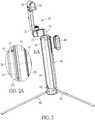
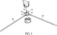
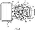
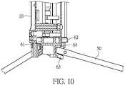
FIG. 1 is a schematic view showing the overall structure of the selfie stick in the first embodiment.FIG. 2 is a schematic structural view showing an extended state of the selfie stick in the first embodiment.FIG. 3 is a schematic exploded view showing a partial structure of the selfie stick in the first embodiment.FIG. 4 is a cross-sectional structural view of the selfie stick in the first embodiment.FIG. 5 is a partial cross-sectional view showing an extended state of the selfie stick in the first embodiment.FIG. 6 is a schematic view showing the locking structure of the selfie stick in the first embodiment.FIG. 7 is a first perspective view of the locking ring of the second embodiment.FIG. 8 is a second perspective view of the locking ring of the second embodiment.FIG. 9 is a partial exploded view of the support in the second embodiment.FIG. 10 is a partial cross-sectional view of the support of the second embodiment.- DESCRIPTION OF REFERENCE NUMERALS: 10: seat body; 11: cavity; 12: sliding slot; 121: limiting convex rib; 13: threaded hole; 14: first block; 16: receiving slot; 15: retaining slot; 17: second block; 20: telescopic rod; 30: clamping portion; 31: first clamping arm; 32: second clamping arm; 33: connecting arm; 34: clamping space; 35: fill light; 36: support arm; 40: wireless remote control; 41: sliding rail; 42: limiting slot; 50: support feet; 60: locking ring; 61: ring body; 62: rod; 63: baffle; 64: sub-baffle
- The invention will be further described in detail below with reference to the accompanying drawings.
- The present description is only an explanation of the present invention, and is not intended to limit the present invention.
- The first embodiment: this embodiment relates to a selfie stick with a support. As shown in
FIG. 1-6 , the selfie stick includes aclamping portion 30, atelescopic rod 20 and a support, but it should be noted that in addition to the adaptation to the selfie stick, the support can also be used as a support for other devices such as lights, fans, measuring instruments, and the like. - The
clamping portion 30 is connected to thetelescopic rod 20 for clamping a mobile phone, and the support comprises aseat body 10, asupport foot 50 and a locking structure. - As a preferred
clamping portion 30, theclamping portion 30 includes afirst clamping arm 31, asecond clamping arm 32, and a connectingarm 33. Thesecond clamp arm 32 is elastically stretchable relative to thefirst clamp arm 31 and forms aclamping space 34 for clamping a mobile phone. Thesecond clamp arm 32 is provided with afill light 35 hinged to thesecond clamp arm 32. Thesecond clamp arm 32 has twosupport arms 36 which are disposed oppositely to each other. Thefill light 35 is disposed between the twosupport arms 36. - Further, the
fill light 35 has a cylindrical shape and is rotatable between thesupport arms 36, thereby adjusting the illumination angle of thefill light 35. - Further, one end of the connecting
arm 33 is hinged to thefirst clamping arm 31, and the other end of the connectingarm 33 is hinged to thetelescopic rod 20. Theclamping portion 30 can realize a relative rotation of the connectingarm 33 and theseat body 10, thereby facilitating receiving and adjustment of the angle. - The
seat body 10 is a cylindrical casing having an open end, and theseat body 10 has acavity 11 therein for thetelescopic rod 20 to be folded. The bottom of theseat body 10 and the main body of theseat body 10 may be an integrated structure, or may be fixedly connected by two separate parts. A control circuit board and a battery are disposed in theseat body 10, and the control circuit board and the battery are permanent components in the selfie stick. The prior art is not the focus of the present application, and details are not described herein. - The outer surface of the
seat body 10 is detachably fitted with awireless remote controller 40. Theseat body 10 is provided with asliding slot 12, and thewireless remote controller 40 is provided with a slidingrail 41 adapted to thesliding slot 12. A limitingconvex rib 121 is disposed in the slidingslot 12, and a limitingrail 42 is matched with the limitingconvex rib 121. The bottom of theseat body 10 is provided with a threadedhole 13 for fitting with a gimbal or a tripod. - The lower end of the
telescopic rod 20 is fixedly mounted in theseat body 10, and the upper end of thetelescopic rod 20 is connected to the clampingportion 30. A plurality ofsupport feet 50 are provided and the plurality ofsupport feet 50 are hinged to the bottom of theseat body 10. Preferably, thesupport feet 50 are provided with three, and the threesupport feet 50 are hinged to the bottom of theseat body 10, and the threesupport feet 50 are foldably stored on theseat body 10. As a preferred hinge method, theseat body 10 is provided with a receivingslot 16 adapted to eachsupport foot 50. Eachsupport foot 50 is folded upward and then integrally stored in the receivingslot 16. Specifically, one end of thesupport foot 50 is hinged to the bottom of theseat body 10, the hinge is disposed in a region of the receivingslot 16 at the bottom of theseat body 10, a hinge shaft perpendicular to the stretching direction of thetelescopic rod 20 is formed in the region, and thesupport foot 50 can be flipped up and down along the hinge axis. - In order to prevent the
support foot 50 stored in the receivingslot 16 from detaching from the receivingslot 16 at the time of carrying, the receivingslot 16 is provided with a holding structure for holding thesupport foot 50 in the receivingslot 16 at all times. - As a preferred holding structure, an elastic rubber portion is provided on the side of the
support foot 50 away from the hinge shaft. The holding structure includes afirst block 14 and asecond block 17. Thefirst block 14 is disposed on the inner wall of the receivingslot 16. Thesecond block 17 is disposed on the inner wall of the receivingslot 16 and symmetrically arranged with thefirst block 14. Thesecond block 17 is for engaging with thefirst block 14 so as to engage with the elastic rubber portion on thesupport foot 50 in the receivingslot 16. That is, after thesupport foot 50 is engaged in the receivingslot 16, the threesupport foot 50 is firmly stored in the receivingslot 16 by the provided holding structure. - In this embodiment, the locking structure is disposed at the bottom of the
seat body 10, and the threesupport feet 50 are extended and locked by the locking structure to support theseat body 10. - As a preferred locking structure, the locking structure is a locking
ring 60. The lockingring 60 includes aring body 61, arod 62 and a plurality ofbaffles 63 corresponding to thesupport feet 50. When the number of thesupport feet 50 is three, the number of thebaffles 63 is preferably also three, and each of thebaffles 63 corresponds to onesupport foot 50. Therod 62 and thebaffle 63 are fixedly connected to thering body 61. Thering body 61 is rotatably disposed in theseat body 10. Theseat body 10 is provided with a retainingslot 15 for the rotation of therod 62, and therod 62 extends out of theseat body 10 from the retainingslot 16, so that the user can rotate therod 62 from the outside of theseat body 10, and the rotation of therod 62 drives thebaffle 63 to rotate. - In this embodiment, when the plurality of
support feet 50 are in an extended state, thebaffle 63 is configured to abut against thecorresponding support foot 50 from below after rotating with therod 62 to a preset position, so that thesupport feet 50 can be prevented from rotating to support theseat body 10. Besides, thebaffle 63 is configured to disengage from thesupport feet 50 after rotating with therod 62, so that thesupport feet 50 can be rotated to fold upward. - As a preferred configuration implementation of the
baffle 63, the plurality ofbaffles 63 are spaced apart from the outer periphery of the bottom of thering body 61 and extend obliquely and downward with respect to thering body 61 by a predetermined length. When the plurality ofsupport feet 50 are in an extended state, thebaffle 63 abuts against thecorresponding support foot 50 from below. Since thebaffle 63 abuts against thecorresponding support foot 50 from below, thesupport foot 50 cannot be rotated when the plurality ofsupport feet 50 are in an extended state. When thebaffle 63 rotates with therod 62 to the position where it disengages from one end of the support foot 50 (i.e., thebaffle 63 no longer abuts against thecorresponding support foot 50 from below, and thesupport foot 50 is located at a gap between adjacent baffles 63), thesupport foot 50 can be rotated to fold upward. - Preferably, any one of the plurality of
support feet 50 which is not in an extended state is located between the twobaffles 63 to prevent thebaffle 63 from rotating, so that the plurality ofsupport feet 50 are all in an extended state at the same time when being locked. Specifically, at this time, before the threesupport feet 50 are not completely extended, thesupport feet 50 which are not extended are located between the twobaffles 63, so that thebaffles 63 are blocked by thesupport feet 50 and cannot be rotated. - The working principle of this embodiment is substantially as follows: when the
support foot 50 is extended to support theseat body 10, thesupport foot 50 is driven out of the holding structure by an external force, and is turned down around the hinge axis. After all thesupport feet 50 are rotated to the desired position, therod 62 is rotated, so that therod 62 drives thering body 61 to rotate, and when thebaffle 63 is rotated to the lower side of thecorresponding support foot 50 and abuts against thesupport foot 50, rotation of therod 62 is stopped, thereby locking thesupport foot 50 at the current position to ensure that thesupport foot 50 can provide stable and effective support to theseat body 10. When folding thesupport foot 50, therod 62 is driven to return to the original position, and thebaffle 63 is again rotated by thering body 61, so that thebaffle 63 is disengaged from thesupport foot 50 and the locking structure unlocks thesupport foot 50. Then thesupport foot 50 is rotated upward by the hinge axis, enabling thesupport foot 50 to be stored in the receivingslot 16 gradually. After that, the elastic rubber portion on thesupport foot 50 is engaged with the holding structure to complete the receiving of thesupport foot 50. The selfie stick adopting the above support has the advantages of light weight, convenient carrying, compact structure, simple operation, simple appearance, beautiful appearance and good stability after receiving. - The second embodiment is different from the first embodiment in that, as shown in
FIG. 9 andFIG. 10 , in the embodiment, the lockingring 60 further includes a sub-baffle 64 disposed on a peripheral portion of thering body 61, wherein a predetermined gap is formed between the sub-baffle 64 and thebaffle 63 in a vertical direction. In a preferred embodiment, the number of the sub-baffles 64 is plural, and the number of the sub-baffles 64 corresponds to the number of thebaffles 63. For example, when the number of thebaffles 63 is three, the number of the sub-baffles 64 is also three, and each sub-baffle 64 corresponds to onebaffle 63. A predetermined gap is formed between each sub-baffle 64 and thecorresponding baffle 63 in a vertical direction. In another preferred embodiment, the sub-baffle 64 can also be a structure of full circle surrounding thering body 61. - Further, as shown in FIGS. 11 and 12, in the support and the selfie stick with the support, the sub-baffle 64 is configured to abut against the
corresponding support foot 50 from above when the plurality ofsupport feet 50 are in an extended state to prevent thesupport foot 50 from rotating to support theseat body 10. That is, when the plurality ofsupport feet 50 are in an extended state, the sub-baffle 64 is located above thecorresponding support foot 50, thebaffle 63 is located below thecorresponding support foot 50, the sub-baffle 64 abuts against thesupport foot 50 from above, and thebaffle 63 abuts against thesupport foot 50 from below. Since the sub-baffle 64 is provided, the sub-baffle 64 can abut against thesupport foot 50 to prevent the contact portion of therod 62 or of theseat body 10 from suffering damage. - Preferably, one or more of the sub-baffles 64 and the
baffles 63 are configured with a hard characteristic, and its hard properties are preferably derived from its material properties, for example, made of a metallic material.
Claims (14)
- A support, comprising:a seat body (10), on which a receiving slot (16) is provided;a support foot (50) provided on the seat body (10) and rotatable relative to the seat body (10), the support foot (50) being configured to be extended to support the seat body (10) or to be folded for being received in the receiving slot (16); anda locking structure provided on the seat body (10) for locking the support foot (50) to support the seat body (10) atter the support toot (50) is extended, or for unlocking the support toot (50) to enable the support toot (50) to be received when the support toot (50) is folded,wherein a holding structure adapted to the support foot (50) is provided in the receiving slot (16) for preventing the support foot (50) from detaching from the receiving slot (16) after being stored,wherein the holding structure comprises:a first block (14) disposed on an inner wall of the receiving slot (16); anda second block (17) disposed on the inner wall of the receiving slot (16) and symmetrically arranged with the first block (14) for cooperating with the first block (14) to latch the support foot (50) in the receiving slot (16), andcharacterized in that the locking structure is a locking ring (60) and a retaining slot (15) is provided on the seat body (10), wherein the locking ring (60) comprises:a ring body (61) rotatably mounted in the seat body (10);a baffle (63) affixed to the ring body (61) and simultaneously rotatable with the ring body (61) for locking the support foot (50) when the support foot (50) is extended or for unlocking the support foot (50) when the support foot (50) is folded, anda rod (62), wherein one end of the rod (62) is fixedly assembled with the ring body (61) and the other end of the rod (62) is movably accommodated in the retaining slot (15) for driving the ring body (61) to rotate to drive the baffle (63) to rotate.
- The support according to claim 1, wherein a plurality of the baffles (63) are provided at intervals on an outer side wall of the ring body (61) at one side away from the rod (62);
wherein, when the support foot (50) is in an extended state and used to support the seat body (10), the baffle (63) is rotated with the rod (62) to a preset position and used for abutting against the corresponding support foot (50) to prevent the support foot (50) from rotating from one direction to support the seat body (10);
wherein, when the support foot (50) is folded, the baffle (63) is rotated with the rod (62) and disengages from the support foot (50) to make the support foot (50) to be stored in the receiving slot (16) after the support foot (50) rotates relative to the seat body (10). - The support according to claim 2, wherein a plurality of support feet (50) are provided, and the baffles (63) are disposed in one-to-one correspondence with the support feet (50); wherein, when the support foot (50) is not fully extended, the support foot (50) is located between two adjacent baffles (63) to prevent the baffle (63) from rotating, so that the baffles (63) are rotatable only when the plurality of support feet (50) are fully extended.
- The support according to claim 3, wherein the locking ring (60) further comprises a sub-baffle (64) disposed on a peripheral portion of the ring body (61), wherein a predetermined gap is formed between the sub-baffle (64) and the baffle (63) in a vertical direction;
wherein, when the plurality of support feet (50) are all in an extended state, the sub-baffle (64) is rotated with the rod (62) to a preset position for abutting against the corresponding support foot (50) to prevent the support foot (50) from rotating in another direction to support the seat body (10). - A selfie stick with a support, comprising:a clamping portion (30), a telescopic rod (20); anda support,wherein the clamping portion (30) is connected to the telescopic rod (20) for clamping a mobile phone, and the support comprises:a seat body (10), on which a receiving slot (16) is provided, a cavity (11) provided on the seat body (10) for enabling the telescopic rod (20) to be folded inside the seat body (10);a support foot (50) provided on the seat body (10) and rotatable relative to the seat body (10), the support foot (50) being configured to be extended to support the seat body (10) or to be folded for being received in the receiving slot (16); anda locking structure provided on the seat body (10) for locking the support foot (50) to support the seat body (10) after the support foot (50) is extended, or for unlocking the support foot (50) to enable the support foot (50) to be received when the support foot (50) is folded,wherein a holding structure adapted to the support foot (50) is provided in the receiving slot (16) for preventing the support foot (50) from detaching from the receiving slot (16) after being stored,wherein the holding structure comprises:a first block (14) disposed on an inner wall of the receiving slot (16); anda second block (17) disposed on the inner wall of the receiving slot (16) and symmetrically arranged with the first block (14) for cooperating with the first block (14) to latch the support foot (50) in the receiving slot (16),wherein the locking structure is a locking ring (60) and a retaining slot (15) is provided on the seat body (10), wherein the locking ring (60) comprises:a ring body (61) rotatably mounted in the seat body (10);a baffle (63) affixed to on the ring body (61) and simultaneously rotatable with the ring body (61) for locking the support foot (50) when the support foot (50) is extended or for unlocking the support foot (50) when the support foot (50) is folded; anda rod (62), wherein one end of the rod (62) is fixedly assembled with the ring body (61) and the other end of the rod (62) is movably accommodated in the retaining slot (15) for driving the ring body (61) to rotate to drive the baffle (63) to rotate.
- The selfie stick with a support according to claim 5, wherein a plurality of the baffles (63) are provided at intervals on an outer side wall of the ring body (61) at one side away from the rod (62);
wherein, when the support foot (50) is in an extended state and used to support the seat body (10), the baffle (63) is rotated with the rod (62) to a preset position and used for abutting against the corresponding support foot (50) to prevent the support foot (50) from rotating from one direction to support the seat body (10);
wherein, when the support foot (50) is folded, the baffle (63) is rotated with the rod (62) and disengages from the support foot (50) to make the support foot (50) to be stored in the receiving slot (16) after the support foot (50) rotates relative to the seat body (10). - The selfie stick with a support according to claim 6, wherein a plurality of support feet (50) are provided, and the baffles (63) are disposed in one-to-one correspondence with the support feet (50); wherein, when the support foot (50) is not fully extended, the support foot (50) is located between two adjacent baffles (63) to prevent the baffle (63) from rotating, so that the baffles (63) arc rotatable only when the plurality of support feet (50) are fully extended.
- The selfie stick with a support according to claim 7, wherein the locking ring (60) further comprises a sub-baffle (64) disposed on a peripheral portion of the ring body (61), wherein a predetermined gap is formed between the sub-baffle (64) and the baffle (63) in a vertical direction;
wherein, when the plurality of support feet (50) are all in an extended state, the sub-baffle (64) is rotated with the rod (62) to a preset position for abutting against the corresponding support foot (50) to prevent the support foot (50) from rotating in another direction to support the seat body (10). - The selfie stick with a support according to claim 5, wherein the clamping portion (30) comprises: a first clamping arm (31), a second clamping arm (32) and a connecting arm (33); wherein the second clamping arm (32) is elastically stretchable relative to the first clamping arm (31) and forms a clamping space (34) for clamping a mobile phone, and a fill light (35) hinged to the second clamp arm (32) is provided on the second clamping arm (32), the second clamp arm (32) has two support arms (36) disposed oppositely to each other, and the fill light (35) is provided between the two support arms (36); wherein one end of the connecting arm (33) is hinged to the first clamping arm (31), and the other end of the connecting arm (33) is hinged to the telescopic rod (20).
- The selfie stick with a support according to claim 6, wherein a holding structure adapted to the support foot (50) is provided in the receiving slot (16), and is used for preventing the support foot (50) from detaching from the receiving slot (16) after being stored.
- The selfie stick with a support according to claim 7, wherein the holding structure comprises: a first block (14) disposed on an inner wall of the receiving slot (16), and a second block (17) disposed on an inner wall of the receiving slot (16) and symmetrically arranged with the first block (14) for cooperating with the first block (14) to latch the support foot (50) in the receiving slot (16).
- The selfie stick with a support according to claim 9, wherein a detachable wireless remote controller (40) is provided on an outer surface of the seat body (10), a sliding slot (12) is provided in the seat body (10), the wireless remote controller (40) is provided with a sliding rail (41) adapted to the sliding slot (12), a limiting convex rib (121) is arranged in the sliding slot (12), and a limiting slot (42) adapted to the limiting convex rib (121) is provided in the sliding rail (41).
- The selfie stick with a support according to claim 10, wherein a holding structure adapted to the support foot (50) is provided in the receiving slot (16), and is used for preventing the support foot (50) from detaching from the receiving slot (16) after being stored.
- The selfie stick with a support according to claim 11, wherein the holding structure comprises: a first block (14) disposed on an inner wall of the receiving slot (16), and a second block (17) disposed on an inner wall of the receiving slot (16) and symmetrically arranged with the first block (14) for cooperating with the first block (14) to latch the support foot (50) in the receiving slot (16).
Applications Claiming Priority (2)
| Application Number | Priority Date | Filing Date | Title |
|---|---|---|---|
| CN201820997599 | 2018-06-27 | ||
| CN201821389849.2UCN209557997U (en) | 2018-06-27 | 2018-08-28 | Bracket and self-shooting bar with it |
Publications (2)
| Publication Number | Publication Date |
|---|---|
| EP3591467A1 EP3591467A1 (en) | 2020-01-08 |
| EP3591467B1true EP3591467B1 (en) | 2021-05-26 |
Family
ID=67115262
Family Applications (1)
| Application Number | Title | Priority Date | Filing Date |
|---|---|---|---|
| EP19182928.2AActiveEP3591467B1 (en) | 2018-06-27 | 2019-06-27 | Support and selfie stick with support |
Country Status (6)
| Country | Link |
|---|---|
| US (1) | US10718466B2 (en) |
| EP (1) | EP3591467B1 (en) |
| KR (1) | KR200493457Y1 (en) |
| CN (2) | CN209084303U (en) |
| TW (1) | TWM583909U (en) |
| WO (1) | WO2020001009A1 (en) |
Families Citing this family (34)
| Publication number | Priority date | Publication date | Assignee | Title |
|---|---|---|---|---|
| KR102082169B1 (en)* | 2018-11-30 | 2020-02-27 | 주식회사 상상해 | Smart Phone Cradle Case for Self Camera |
| USD907687S1 (en)* | 2019-01-31 | 2021-01-12 | Guixiong Fang | Selfie stick with tripod |
| CN210266648U (en)* | 2019-03-27 | 2020-04-07 | 源德盛塑胶电子(深圳)有限公司 | Clamping mechanism and handheld cloud platform |
| JP1659753S (en)* | 2019-04-11 | 2020-05-18 | ||
| USD950039S1 (en)* | 2019-06-27 | 2022-04-26 | The Coleman Company, Inc. | Fan |
| USD910160S1 (en)* | 2019-07-08 | 2021-02-09 | Arctic-Air Home Appliance Co., Ltd. | Fan |
| USD911427S1 (en)* | 2019-09-10 | 2021-02-23 | Caddie View Llc | Tripod for camera phones |
| CN110544372A (en)* | 2019-09-25 | 2019-12-06 | 东莞信雅电子科技有限公司 | Miniature plug-in wireless bluetooth remote controller |
| CN111131581A (en)* | 2020-01-16 | 2020-05-08 | 深圳市姐哩好科技有限公司 | Take tripod support function from rapping bar |
| CN212251923U (en)* | 2020-01-20 | 2020-12-29 | 深圳市全天拍科技有限公司 | Shooting equipment support with auxiliary handle |
| KR200494557Y1 (en)* | 2020-05-11 | 2021-11-05 | 팬 이글 | Foldable three-section clamping device |
| US20230175643A1 (en)* | 2020-06-08 | 2023-06-08 | BT5 Technologies, LLC | Portable meetings presentation and recorder system |
| CN113833965A (en)* | 2020-06-24 | 2021-12-24 | 广东思锐光学股份有限公司 | A handle-type auxiliary shooting device |
| CN213028148U (en)* | 2020-06-29 | 2021-04-20 | 源德盛塑胶电子(深圳)有限公司 | Mobile phone clamping device |
| USD1074659S1 (en)* | 2020-06-30 | 2025-05-13 | Winners' Sun Plastic & Electronic (Shenzhen) Co., Ltd. | Phone holder |
| USD1067754S1 (en)* | 2020-08-01 | 2025-03-25 | Shenzhen Haohualianhe Technology Co., Ltd. | Holding device |
| JP1701162S (en)* | 2020-09-19 | 2021-11-29 | ||
| CN112197757B (en)* | 2020-10-13 | 2022-06-14 | 中国建筑第八工程局有限公司 | Leveling device is assisted to total powerstation small prism |
| USD967392S1 (en)* | 2020-11-09 | 2022-10-18 | Vornado Air, Llc | Fan base |
| USD967394S1 (en)* | 2020-11-09 | 2022-10-18 | Vornado Air, Llc | Fan grill |
| CN113639166A (en)* | 2021-08-05 | 2021-11-12 | 安徽泓杰人体工学科技有限公司 | Convenient folding legs |
| CN114001257B (en)* | 2021-11-19 | 2023-08-15 | 杭州背包智能网络科技有限公司 | Floor type direct seeding all-in-one machine |
| USD1006980S1 (en)* | 2021-12-14 | 2023-12-05 | Xiaobo Fan | Electric fan |
| USD965134S1 (en)* | 2022-01-05 | 2022-09-27 | Xiuwei Lin | Fan |
| USD1023116S1 (en)* | 2022-01-25 | 2024-04-16 | Shenzhen Haohualianhe Technology Co., Ltd. | Photographing support |
| US20230246473A1 (en)* | 2022-01-30 | 2023-08-03 | Hu Ruan | Mobile power supply |
| USD1002709S1 (en)* | 2022-06-20 | 2023-10-24 | Guixiong Fang | Selfie stick |
| CN115628379B (en)* | 2022-10-21 | 2025-03-11 | 中山宝益五金塑胶制品有限公司 | A bracket with built-in three-cut seat |
| CN115638338A (en)* | 2022-10-24 | 2023-01-24 | 云南电网有限责任公司电力科学研究院 | Open-air monitoring support |
| USD1025189S1 (en)* | 2022-12-19 | 2024-04-30 | Arashi Vision Inc. | Gimbal |
| USD1093470S1 (en) | 2023-03-10 | 2025-09-16 | Annex Products Pty Ltd | Tripod |
| USD1042603S1 (en)* | 2023-03-20 | 2024-09-17 | Shenzhen Dreamlife Innovation Technology Co., Ltd | Handheld stabilizer |
| CN116980511A (en)* | 2023-06-26 | 2023-10-31 | 深圳市优篮子科技有限公司 | Folding self-timer rod |
| USD1035754S1 (en)* | 2023-07-13 | 2024-07-16 | Kong Yang | Mobile phone holder |
Family Cites Families (22)
| Publication number | Priority date | Publication date | Assignee | Title |
|---|---|---|---|---|
| CN204119349U (en)* | 2014-09-11 | 2015-01-21 | 源德盛塑胶电子(深圳)有限公司 | A kind of integral type self-timer |
| US9298066B1 (en)* | 2014-10-28 | 2016-03-29 | Eagle Fan | Multi-functional support assembly |
| KR200481747Y1 (en)* | 2015-02-24 | 2016-11-04 | 박범진 | Tripod for selfie stick |
| DE202015001540U1 (en)* | 2015-02-27 | 2015-06-08 | Eagle Fan | Swivel head for a tripod |
| KR20160129507A (en)* | 2015-04-30 | 2016-11-09 | 에이스그룹 주식회사 | Assistance device for self-camera |
| CN105443949A (en)* | 2015-06-02 | 2016-03-30 | 华尔达(厦门)塑胶有限公司 | Selfie stick structure |
| KR101667394B1 (en)* | 2015-08-25 | 2016-10-19 | (주) 에셀티 | handheld and wearable stabilizer that assist in holding mobile gadgets |
| CN204986297U (en)* | 2015-09-08 | 2016-01-20 | 华尔达(厦门)塑胶有限公司 | From rapping bar structure |
| US10414332B2 (en)* | 2015-10-22 | 2019-09-17 | Bong Cheol Kim | Vehicle emergency safety device using selfie stick |
| US9685986B2 (en)* | 2015-11-05 | 2017-06-20 | Htc Corporation | Device cover for accessory attachment |
| CN205232329U (en)* | 2015-12-23 | 2016-05-11 | 深圳市随身秀时尚创意科技有限公司 | Integral type is from rapping bar |
| WO2017152391A1 (en)* | 2016-03-09 | 2017-09-14 | 深圳市琇莹印刷有限公司 | Portable selfie stick |
| US9995442B2 (en)* | 2016-05-22 | 2018-06-12 | Eagle Fan | Multi-function portable lighting apparatus |
| BR112019002288A2 (en)* | 2016-08-07 | 2019-06-18 | Stikbox Tech Limited | Mobile phone and back panel of the same susceptible to retractable selfie stick |
| CN107781595A (en)* | 2016-08-24 | 2018-03-09 | 余姚市高凯电子厂 | A kind of self-shooting bar |
| US20180106418A1 (en)* | 2016-10-13 | 2018-04-19 | Troy Anglin | Imaging stand |
| CN107820705A (en)* | 2016-11-04 | 2018-03-20 | 深圳市柔宇科技有限公司 | Self-shooting bar and the method that capture apparatus is controlled by self-shooting bar |
| US10488741B2 (en)* | 2017-05-02 | 2019-11-26 | Anthony C. Prichard | Support apparatus |
| KR101819452B1 (en)* | 2017-05-02 | 2018-02-28 | 주식회사 워브코리아 | Useful selfie stick for night shots |
| CN207394254U (en)* | 2017-09-26 | 2018-05-22 | 上海工程技术大学 | A kind of light filling formula self-shooting bar |
| CN107654818A (en)* | 2017-10-24 | 2018-02-02 | 中山立信摄影器材有限公司 | One kind folds self-shooting bar |
| CN207410397U (en)* | 2017-11-13 | 2018-05-25 | 周文化 | Portable multifunctional handset bracket is precious |
- 2018
- 2018-08-28CNCN201821389746.6Upatent/CN209084303U/enactiveActive
- 2018-08-28CNCN201821389849.2Upatent/CN209557997U/enactiveActive
- 2019
- 2019-01-18WOPCT/CN2019/072327patent/WO2020001009A1/ennot_activeCeased
- 2019-06-12TWTW108207441Upatent/TWM583909U/ennot_activeIP Right Cessation
- 2019-06-27USUS16/454,216patent/US10718466B2/enactiveActive
- 2019-06-27KRKR2020190002707Upatent/KR200493457Y1/ennot_activeExpired - Fee Related
- 2019-06-27EPEP19182928.2Apatent/EP3591467B1/enactiveActive
Also Published As
| Publication number | Publication date |
|---|---|
| CN209084303U (en) | 2019-07-09 |
| US20200072411A1 (en) | 2020-03-05 |
| CN209557997U (en) | 2019-10-29 |
| WO2020001009A1 (en) | 2020-01-02 |
| EP3591467A1 (en) | 2020-01-08 |
| US10718466B2 (en) | 2020-07-21 |
| KR200493457Y1 (en) | 2021-04-05 |
| KR20200000515U (en) | 2020-03-09 |
| TWM583909U (en) | 2019-09-21 |
Similar Documents
| Publication | Publication Date | Title |
|---|---|---|
| EP3591467B1 (en) | Support and selfie stick with support | |
| EP4023924B1 (en) | Foldable device and foldable fan and foldable table lamp applicable thereto | |
| CN210152944U (en) | Foldable fan | |
| EP3715695B1 (en) | Clamping mechanism and handheld gimbal | |
| CN210831132U (en) | Handheld stabilizer's holder adjusting device and handheld stabilizer | |
| JP3222965U (en) | Stand and selfie stick with stand | |
| CN202868219U (en) | Multifunctional viewing and shooting handle support frame | |
| CN218237260U (en) | Supporting seat, fan and lamp | |
| KR20220012778A (en) | handheld stabilizer | |
| US12146607B2 (en) | Gimbal | |
| CN213628066U (en) | Folding fan | |
| CN212480794U (en) | A handheld stabilizer | |
| KR20180039789A (en) | Smart Phone Cradle Case for Self Camera | |
| WO2021258407A1 (en) | Handle-type auxiliary photographing device | |
| CN208901011U (en) | A kind of full storage tripod self-shooting bar | |
| TW201813363A (en) | Pedestal for adjusting interface position | |
| CN217208728U (en) | Holding member can hide receipts folding from rapping bar | |
| CN214947839U (en) | Support mechanism and shooting device | |
| CN220337950U (en) | Tripod head | |
| CN218467873U (en) | Small folding mute fan | |
| CN220379340U (en) | Shooting accessory and shooting assembly | |
| CN216692904U (en) | Cloud platform | |
| CN120537956A (en) | Magnetic support and photographic handle |
Legal Events
| Date | Code | Title | Description |
|---|---|---|---|
| PUAI | Public reference made under article 153(3) epc to a published international application that has entered the european phase | Free format text:ORIGINAL CODE: 0009012 | |
| STAA | Information on the status of an ep patent application or granted ep patent | Free format text:STATUS: THE APPLICATION HAS BEEN PUBLISHED | |
| AK | Designated contracting states | Kind code of ref document:A1 Designated state(s):AL AT BE BG CH CY CZ DE DK EE ES FI FR GB GR HR HU IE IS IT LI LT LU LV MC MK MT NL NO PL PT RO RS SE SI SK SM TR | |
| AX | Request for extension of the european patent | Extension state:BA ME | |
| STAA | Information on the status of an ep patent application or granted ep patent | Free format text:STATUS: REQUEST FOR EXAMINATION WAS MADE | |
| 17P | Request for examination filed | Effective date:20200708 | |
| RBV | Designated contracting states (corrected) | Designated state(s):AL AT BE BG CH CY CZ DE DK EE ES FI FR GB GR HR HU IE IS IT LI LT LU LV MC MK MT NL NO PL PT RO RS SE SI SK SM TR | |
| GRAP | Despatch of communication of intention to grant a patent | Free format text:ORIGINAL CODE: EPIDOSNIGR1 | |
| STAA | Information on the status of an ep patent application or granted ep patent | Free format text:STATUS: GRANT OF PATENT IS INTENDED | |
| INTG | Intention to grant announced | Effective date:20201204 | |
| GRAS | Grant fee paid | Free format text:ORIGINAL CODE: EPIDOSNIGR3 | |
| GRAA | (expected) grant | Free format text:ORIGINAL CODE: 0009210 | |
| STAA | Information on the status of an ep patent application or granted ep patent | Free format text:STATUS: THE PATENT HAS BEEN GRANTED | |
| AK | Designated contracting states | Kind code of ref document:B1 Designated state(s):AL AT BE BG CH CY CZ DE DK EE ES FI FR GB GR HR HU IE IS IT LI LT LU LV MC MK MT NL NO PL PT RO RS SE SI SK SM TR | |
| REG | Reference to a national code | Ref country code:GB Ref legal event code:FG4D | |
| REG | Reference to a national code | Ref country code:CH Ref legal event code:EP | |
| REG | Reference to a national code | Ref country code:AT Ref legal event code:REF Ref document number:1396816 Country of ref document:AT Kind code of ref document:T Effective date:20210615 | |
| REG | Reference to a national code | Ref country code:DE Ref legal event code:R096 Ref document number:602019004831 Country of ref document:DE | |
| REG | Reference to a national code | Ref country code:IE Ref legal event code:FG4D | |
| REG | Reference to a national code | Ref country code:LT Ref legal event code:MG9D | |
| REG | Reference to a national code | Ref country code:AT Ref legal event code:MK05 Ref document number:1396816 Country of ref document:AT Kind code of ref document:T Effective date:20210526 | |
| PG25 | Lapsed in a contracting state [announced via postgrant information from national office to epo] | Ref country code:AT Free format text:LAPSE BECAUSE OF FAILURE TO SUBMIT A TRANSLATION OF THE DESCRIPTION OR TO PAY THE FEE WITHIN THE PRESCRIBED TIME-LIMIT Effective date:20210526 Ref country code:BG Free format text:LAPSE BECAUSE OF FAILURE TO SUBMIT A TRANSLATION OF THE DESCRIPTION OR TO PAY THE FEE WITHIN THE PRESCRIBED TIME-LIMIT Effective date:20210826 Ref country code:FI Free format text:LAPSE BECAUSE OF FAILURE TO SUBMIT A TRANSLATION OF THE DESCRIPTION OR TO PAY THE FEE WITHIN THE PRESCRIBED TIME-LIMIT Effective date:20210526 Ref country code:HR Free format text:LAPSE BECAUSE OF FAILURE TO SUBMIT A TRANSLATION OF THE DESCRIPTION OR TO PAY THE FEE WITHIN THE PRESCRIBED TIME-LIMIT Effective date:20210526 Ref country code:LT Free format text:LAPSE BECAUSE OF FAILURE TO SUBMIT A TRANSLATION OF THE DESCRIPTION OR TO PAY THE FEE WITHIN THE PRESCRIBED TIME-LIMIT Effective date:20210526 | |
| REG | Reference to a national code | Ref country code:NL Ref legal event code:MP Effective date:20210526 | |
| PG25 | Lapsed in a contracting state [announced via postgrant information from national office to epo] | Ref country code:GR Free format text:LAPSE BECAUSE OF FAILURE TO SUBMIT A TRANSLATION OF THE DESCRIPTION OR TO PAY THE FEE WITHIN THE PRESCRIBED TIME-LIMIT Effective date:20210827 Ref country code:IS Free format text:LAPSE BECAUSE OF FAILURE TO SUBMIT A TRANSLATION OF THE DESCRIPTION OR TO PAY THE FEE WITHIN THE PRESCRIBED TIME-LIMIT Effective date:20210926 Ref country code:PL Free format text:LAPSE BECAUSE OF FAILURE TO SUBMIT A TRANSLATION OF THE DESCRIPTION OR TO PAY THE FEE WITHIN THE PRESCRIBED TIME-LIMIT Effective date:20210526 Ref country code:LV Free format text:LAPSE BECAUSE OF FAILURE TO SUBMIT A TRANSLATION OF THE DESCRIPTION OR TO PAY THE FEE WITHIN THE PRESCRIBED TIME-LIMIT Effective date:20210526 Ref country code:NO Free format text:LAPSE BECAUSE OF FAILURE TO SUBMIT A TRANSLATION OF THE DESCRIPTION OR TO PAY THE FEE WITHIN THE PRESCRIBED TIME-LIMIT Effective date:20210826 Ref country code:PT Free format text:LAPSE BECAUSE OF FAILURE TO SUBMIT A TRANSLATION OF THE DESCRIPTION OR TO PAY THE FEE WITHIN THE PRESCRIBED TIME-LIMIT Effective date:20210927 Ref country code:SE Free format text:LAPSE BECAUSE OF FAILURE TO SUBMIT A TRANSLATION OF THE DESCRIPTION OR TO PAY THE FEE WITHIN THE PRESCRIBED TIME-LIMIT Effective date:20210526 Ref country code:RS Free format text:LAPSE BECAUSE OF FAILURE TO SUBMIT A TRANSLATION OF THE DESCRIPTION OR TO PAY THE FEE WITHIN THE PRESCRIBED TIME-LIMIT Effective date:20210526 | |
| PG25 | Lapsed in a contracting state [announced via postgrant information from national office to epo] | Ref country code:NL Free format text:LAPSE BECAUSE OF FAILURE TO SUBMIT A TRANSLATION OF THE DESCRIPTION OR TO PAY THE FEE WITHIN THE PRESCRIBED TIME-LIMIT Effective date:20210526 | |
| PG25 | Lapsed in a contracting state [announced via postgrant information from national office to epo] | Ref country code:SK Free format text:LAPSE BECAUSE OF FAILURE TO SUBMIT A TRANSLATION OF THE DESCRIPTION OR TO PAY THE FEE WITHIN THE PRESCRIBED TIME-LIMIT Effective date:20210526 Ref country code:ES Free format text:LAPSE BECAUSE OF FAILURE TO SUBMIT A TRANSLATION OF THE DESCRIPTION OR TO PAY THE FEE WITHIN THE PRESCRIBED TIME-LIMIT Effective date:20210526 Ref country code:EE Free format text:LAPSE BECAUSE OF FAILURE TO SUBMIT A TRANSLATION OF THE DESCRIPTION OR TO PAY THE FEE WITHIN THE PRESCRIBED TIME-LIMIT Effective date:20210526 Ref country code:DK Free format text:LAPSE BECAUSE OF FAILURE TO SUBMIT A TRANSLATION OF THE DESCRIPTION OR TO PAY THE FEE WITHIN THE PRESCRIBED TIME-LIMIT Effective date:20210526 Ref country code:CZ Free format text:LAPSE BECAUSE OF FAILURE TO SUBMIT A TRANSLATION OF THE DESCRIPTION OR TO PAY THE FEE WITHIN THE PRESCRIBED TIME-LIMIT Effective date:20210526 Ref country code:SM Free format text:LAPSE BECAUSE OF FAILURE TO SUBMIT A TRANSLATION OF THE DESCRIPTION OR TO PAY THE FEE WITHIN THE PRESCRIBED TIME-LIMIT Effective date:20210526 Ref country code:RO Free format text:LAPSE BECAUSE OF FAILURE TO SUBMIT A TRANSLATION OF THE DESCRIPTION OR TO PAY THE FEE WITHIN THE PRESCRIBED TIME-LIMIT Effective date:20210526 | |
| REG | Reference to a national code | Ref country code:DE Ref legal event code:R097 Ref document number:602019004831 Country of ref document:DE | |
| REG | Reference to a national code | Ref country code:BE Ref legal event code:MM Effective date:20210630 | |
| PLBE | No opposition filed within time limit | Free format text:ORIGINAL CODE: 0009261 | |
| STAA | Information on the status of an ep patent application or granted ep patent | Free format text:STATUS: NO OPPOSITION FILED WITHIN TIME LIMIT | |
| PG25 | Lapsed in a contracting state [announced via postgrant information from national office to epo] | Ref country code:MC Free format text:LAPSE BECAUSE OF FAILURE TO SUBMIT A TRANSLATION OF THE DESCRIPTION OR TO PAY THE FEE WITHIN THE PRESCRIBED TIME-LIMIT Effective date:20210526 Ref country code:LU Free format text:LAPSE BECAUSE OF NON-PAYMENT OF DUE FEES Effective date:20210627 | |
| PG25 | Lapsed in a contracting state [announced via postgrant information from national office to epo] | Ref country code:IE Free format text:LAPSE BECAUSE OF NON-PAYMENT OF DUE FEES Effective date:20210627 | |
| 26N | No opposition filed | Effective date:20220301 | |
| PG25 | Lapsed in a contracting state [announced via postgrant information from national office to epo] | Ref country code:IS Free format text:LAPSE BECAUSE OF FAILURE TO SUBMIT A TRANSLATION OF THE DESCRIPTION OR TO PAY THE FEE WITHIN THE PRESCRIBED TIME-LIMIT Effective date:20210926 Ref country code:FR Free format text:LAPSE BECAUSE OF NON-PAYMENT OF DUE FEES Effective date:20210726 Ref country code:AL Free format text:LAPSE BECAUSE OF FAILURE TO SUBMIT A TRANSLATION OF THE DESCRIPTION OR TO PAY THE FEE WITHIN THE PRESCRIBED TIME-LIMIT Effective date:20210526 | |
| PG25 | Lapsed in a contracting state [announced via postgrant information from national office to epo] | Ref country code:IT Free format text:LAPSE BECAUSE OF FAILURE TO SUBMIT A TRANSLATION OF THE DESCRIPTION OR TO PAY THE FEE WITHIN THE PRESCRIBED TIME-LIMIT Effective date:20210526 Ref country code:BE Free format text:LAPSE BECAUSE OF NON-PAYMENT OF DUE FEES Effective date:20210630 | |
| REG | Reference to a national code | Ref country code:CH Ref legal event code:PL | |
| PG25 | Lapsed in a contracting state [announced via postgrant information from national office to epo] | Ref country code:LI Free format text:LAPSE BECAUSE OF NON-PAYMENT OF DUE FEES Effective date:20220630 Ref country code:CH Free format text:LAPSE BECAUSE OF NON-PAYMENT OF DUE FEES Effective date:20220630 | |
| PG25 | Lapsed in a contracting state [announced via postgrant information from national office to epo] | Ref country code:CY Free format text:LAPSE BECAUSE OF FAILURE TO SUBMIT A TRANSLATION OF THE DESCRIPTION OR TO PAY THE FEE WITHIN THE PRESCRIBED TIME-LIMIT Effective date:20210526 | |
| PG25 | Lapsed in a contracting state [announced via postgrant information from national office to epo] | Ref country code:HU Free format text:LAPSE BECAUSE OF FAILURE TO SUBMIT A TRANSLATION OF THE DESCRIPTION OR TO PAY THE FEE WITHIN THE PRESCRIBED TIME-LIMIT; INVALID AB INITIO Effective date:20190627 | |
| GBPC | Gb: european patent ceased through non-payment of renewal fee | Effective date:20230627 | |
| PG25 | Lapsed in a contracting state [announced via postgrant information from national office to epo] | Ref country code:MK Free format text:LAPSE BECAUSE OF FAILURE TO SUBMIT A TRANSLATION OF THE DESCRIPTION OR TO PAY THE FEE WITHIN THE PRESCRIBED TIME-LIMIT Effective date:20210526 Ref country code:GB Free format text:LAPSE BECAUSE OF NON-PAYMENT OF DUE FEES Effective date:20230627 | |
| PG25 | Lapsed in a contracting state [announced via postgrant information from national office to epo] | Ref country code:MT Free format text:LAPSE BECAUSE OF FAILURE TO SUBMIT A TRANSLATION OF THE DESCRIPTION OR TO PAY THE FEE WITHIN THE PRESCRIBED TIME-LIMIT Effective date:20210526 | |
| PGFP | Annual fee paid to national office [announced via postgrant information from national office to epo] | Ref country code:DE Payment date:20250618 Year of fee payment:7 |