EP3586727B1 - Vein detection device - Google Patents
Vein detection deviceDownload PDFInfo
- Publication number
- EP3586727B1 EP3586727B1EP19176942.1AEP19176942AEP3586727B1EP 3586727 B1EP3586727 B1EP 3586727B1EP 19176942 AEP19176942 AEP 19176942AEP 3586727 B1EP3586727 B1EP 3586727B1
- Authority
- EP
- European Patent Office
- Prior art keywords
- image
- vein
- brightness interval
- infrared light
- receiver
- Prior art date
- Legal status (The legal status is an assumption and is not a legal conclusion. Google has not performed a legal analysis and makes no representation as to the accuracy of the status listed.)
- Active
Links
Images


Classifications
- A—HUMAN NECESSITIES
- A61—MEDICAL OR VETERINARY SCIENCE; HYGIENE
- A61B—DIAGNOSIS; SURGERY; IDENTIFICATION
- A61B5/00—Measuring for diagnostic purposes; Identification of persons
- A61B5/48—Other medical applications
- A61B5/4887—Locating particular structures in or on the body
- A61B5/489—Blood vessels
- A—HUMAN NECESSITIES
- A61—MEDICAL OR VETERINARY SCIENCE; HYGIENE
- A61B—DIAGNOSIS; SURGERY; IDENTIFICATION
- A61B5/00—Measuring for diagnostic purposes; Identification of persons
- A61B5/0059—Measuring for diagnostic purposes; Identification of persons using light, e.g. diagnosis by transillumination, diascopy, fluorescence
- A61B5/0082—Measuring for diagnostic purposes; Identification of persons using light, e.g. diagnosis by transillumination, diascopy, fluorescence adapted for particular medical purposes
Definitions
- the present inventionrelates to a vein detection device, particularly, to a vein detection device which can display vein images captured by infrared light sensing technology.
- the traditional intravenous injectionrelies on the experience of medical staff. Leaving aside the experience of the medical staff, there is an issue in clinic that many patients have difficulty in finding blood vessels. The reason may be that the innate blood vessels are thinner, or the adipose tissue thickness is too high, and the blood vessels are not easily detected by the naked eye from the outside of the skin. Although veins can also be shown by girdling, it is still very limited.
- US 2017/0188937 A1discloses an artery visualization device for irradiating skin on the wrist back side with near-infrared light and forming near-infrared image of the wrist includes a placement table on which the wrist is placed, an irradiation unit including a light source emitting near-infrared light, imaging unit receiving light and forming wrist near-infrared image, the light incidents on the skin on the wrist back side and exiting from skin on the front, optical filter, and monitor.
- the artery visualization deviceincludes a protrusion protruding from a placement table wrist placement surface.
- the protrusioncompresses the back side skin on the wrist placed on the placement table from the back side, and irradiates the near-infrared light emitted from the light source to the skin on the back.
- WO 96/362731 A2discloses a system and method for enhancing visualization of veins, arteries or other subcutaneous natural or foreign structures of the body and for facilitating intravenous insertion or extraction of fluids, medication or the like in the administration of medical treatment to human or animal subjects are described which comprise a light source for illuminating or transilluminating the corresponding portion of the body with light of selected wavelengths and a low-level light detector such as an image intensifier tube, a photomultiplier tube, photodiode or charge coupled device, for generating an image of the illuminated body portion, and optical filter(s) of selected spectral transmittance which can be located at the light source(s), detector, or both.
- CN 107 788 949 Adiscloses another vein detection device.
- DE 20 2010 000 522 U1discloses a fisheye lamp.
- the present inventiondiscloses a vein detection device, comprising a base, a transmitter, a detection arm, a first receiver and a display.
- the transmitteris configured on the base, wherein the transmitter is attached to an exposed portion to emit an infrared light to the exposed portion.
- the detection armis configured on the base, and it is used to support the first receiver.
- the first receiverreceives a first infrared light image coming from the exposed portion, and the first infrared light image is converted from the infrared light.
- a displayis configured on the base and electrically connected with the first receiver to display a first vein image converted from the first infrared light image.
- the transmitterincludes a lens which may be attached by the exposed portion.
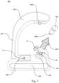
- FIG. 1it shows a schematic diagram of the appearance structure in accordance with one embodiment of the present invention.
- the configuration of the vein detection device 10a of the present inventionis illustrated in the embodiment of Fig. 1 , mainly including a base 100, a transmitter 200, a detection arm 300, a first receiver 400a, and a display 500.
- the transmitter 200is configured (mounted) on the base 100.
- the transmitter 200 of this embodimentis an infrared light transmitter.
- the transmitter 200is closely attached to the exposed portion H and emits infrared light R1 to irradiate the exposed portion H.
- an infrared light R1has wavelengths ranging from 780 to 1400 nanometers (nm), and the exposed portion H is a palm of the human hand.
- the exposed portion Hcan also be a common intravenous injection site including but not limited to thigh, buttock, upper arm, etc.
- the detection arm 300 of the embodimentis configured on the base 100, and the detection arm 300 is used to support (mount) the first receiver 400a.
- the detection arm 300may be provided with at least one joint portion 301 to adjust the position of the first receiver 400a.
- the first receiver 400a of the present embodimentis an infrared camera, and the first receiver 400a receives a first infrared image R2a coming from the exposed portion H.
- the first infrared image R2ais the image converted from the infrared light R1 passing through the exposed portion H.
- the first infrared image R2acontains the image information of various tissues irradiated by the infrared light R1.
- the first infrared image R2aactually includes a first brightness interval image, a vein brightness interval image and a second brightness interval image.
- the brightness of the first brightness interval imageis higher than the brightness of the vein brightness interval image
- the brightness of the vein brightness interval imageis higher than the brightness of the second brightness interval image.
- the infrared light R1is almost absorbed by the vein, so only the image of a certain depth (brightness) interval is taken as the vein brightness interval image.
- the first brightness interval image and the second brightness interval image defined by the brightness respective higher and lower than that of the vein brightness interval imagemay include but not limited to bone tissue image, connective tissue image, adipose tissue image, cartilage tissue image or other tissue cells image.
- the display 500 of this embodimentis arranged on the base 100 and electrically connected with the first receiver 400a. And, the display 500 displays a first vein image V1 converted from the first infrared image R2a. Furthermore, the first vein image V 1 is a conversion image of the above vein brightness interval image, and the first vein image V1 can clearly show the location of the vein.
- the transmitter 200contains a lens 201.
- the lens 201is closely attached to the exposed portion H.
- the term "closely”does not refer to proximity, but also include actual physical contact, which belong to the definition category of the present invention.
- the lens 201is a fisheye lens, and further, it can be a fisheye lens module.
- the lens 201is used to control emitting direction of infrared light R1 emitted by the transmitter emit 200.
- the emitting direction of the infrared light R1is adjusted based-on the position of the exposed portion H and the first receiver 400a. Therefore, through the above-mentioned technical means, it can easily achieve the requirement in this embodiment that the first receiver 400a, the irradiated unit H and the transmitter 200 are located on the same straight line.
- the transmitter 200essentially contains a function of omnidirectionally tracking the location of the exposed portion H. Therefore, the position of the first receiver 400a must also be adjusted through other means, such as at least one joint portion 301, to conform to the definition of the same straight line.
- Fig. 2is a system architecture diagram of another embodiment of the present invention
- Fig. 3is an appearance structure diagram of further embodiment of the present invention.
- the system architecture of the embodiment in Fig. 2further includes a head-mounted display 700 and an auxiliary transmitter 800
- the embodiment in Fig. 3further includes a head-mounted display 700.
- a power supply, a memory, a wireless signal transceiver module and microcontrollermay be provided within the base 100 to provide the power required for the operation of the vein detection device 10a and the vein detection device 10b, as well as the ability to calculate and process images.
- the above-mentioned componentscan be configured as required, and the detailed descriptions are omitted in this embodiment.
- the base 100 of the vein detection device 10bmay be wired or wirelessly electrically connected to the head-mounted display 700.
- the head-mounted display 700may include but not limited to a virtual reality (VR) display or an augmented reality (AR) display. Therefore, the person skilled in the art should realize that the head-mounted display 700 may also include components required for operation, such as a wireless signal transceiver module, a power supply device, a microcontroller, a memory and a display card, which detailed descriptions are omitted.
- the head-mounted display 700is further provided with a second receiver 400b, and a second infrared image R2b coming from the exposed portion H is received by the second receiver 400b, so that the second infrared image R2b is converted to a second vein image V2 and then displayed on the display 500 and the head-mounted display 700 (The display screen is located inside the head-mounted display 700, so Figure 3 does not indicate the location of the second vein image V2).
- the second vein image V2can also be synchronously displayed on the display 500 of base 100.
- the second vein image V2 captured by the head mounted display 700can be seen by other people.
- the display 500is provided with a first image filtering module 600a and the head-mounted display 700 is provided with a second image filtering module 600b, and the first image filtering module 600a and the second image filtering module 600b are connected with the first receiver 400a and the second receiver 400b, respectively.
- the first image filtering module 600a and the second image filtering module 600bare filtered out the first brightness interval image and the second brightness interval image, and only the vein brightness interval image is retained so that the vein brightness interval image is formed to be the first venous image V1 or the second venous image V2 and then displayed on the display 500 of the base 100 or the head-mounted display 700.
- the image filtering module 600a, 600b in this embodimentcan include but not limited to the combination of a filter and a digital signal processor.
- the transmitter 200, the exposed portion H and the second receiver 400bare arranged on a straight line to perform a good detection process.
- the position of the second receiver 400bcan be easily adjusted as the head-mounted display 700 moves.
- the detection arm 300 in the embodiment of Figs. 1-3may be provided with at least one joint portion 301 (such as embedded into the detection arm 300) such that the angle and position of the first receiver 400a can be adjusted arbitrarily by an operator.
- At least one of the above-mentioned joint portion 301may be any kind of mechanical joint structure, including not limited to an axial joint, a spherical joint, an omnidirectional joint, and the combination thereof.
- the vein detection device 10bmay be connected to an auxiliary transmitter 800.
- the auxiliary transmitter 800can be wired or wirelessly connected to the base 100 of the vein detection device 10b.
- the auxiliary transmitter 800is also an infrared transmitter to emit an auxiliary infrared light R3 to irradiate the exposed portion H.
- the purpose of using the auxiliary transmitter 800is that when the first infrared image R2a or the second infrared image R2b is unable to be observed by the vein detection device 10b, the auxiliary transmitter 800 can provide the auxiliary infrared light R3 from another dimension (position) to the exposed portion H.
- the first infrared image R2a sensed by the first receiver 400a or the second infrared image R2b sensed by the second receiver 400bcan be seen clearly.
- the detection arm 300includes a built-in wireless communication transceiver module. As the detection arm 300 is removed from the base 100, it is still capable of communicating with the base 100 and the first receiver 400a is allowed to detect the first infrared image R2a coming from the exposed portion H in a free direction.
Landscapes
- Health & Medical Sciences (AREA)
- Life Sciences & Earth Sciences (AREA)
- Heart & Thoracic Surgery (AREA)
- Surgery (AREA)
- Biophysics (AREA)
- Pathology (AREA)
- Engineering & Computer Science (AREA)
- Biomedical Technology (AREA)
- Veterinary Medicine (AREA)
- Medical Informatics (AREA)
- Molecular Biology (AREA)
- Physics & Mathematics (AREA)
- Animal Behavior & Ethology (AREA)
- General Health & Medical Sciences (AREA)
- Public Health (AREA)
- Vascular Medicine (AREA)
- Measurement Of The Respiration, Hearing Ability, Form, And Blood Characteristics Of Living Organisms (AREA)
- Infusion, Injection, And Reservoir Apparatuses (AREA)
- Image Input (AREA)
Description
- The present invention relates to a vein detection device, particularly, to a vein detection device which can display vein images captured by infrared light sensing technology.
- In traditional western medical system, there are hundreds of ways to give medicine cure. The common ways include oral drugs, injections, drip medicaments or suppositories.
- However, the administration of injections has been an indispensable way of medical practice. Generally speaking, the most common way of injecting is by intravenous injection for giving medicine in safety. The reason for this is that venous blood pressure is lower and therefore less likely to produce a high risk of bleeding after invasive treatment.
- However, the traditional intravenous injection relies on the experience of medical staff. Leaving aside the experience of the medical staff, there is an issue in clinic that many patients have difficulty in finding blood vessels. The reason may be that the innate blood vessels are thinner, or the adipose tissue thickness is too high, and the blood vessels are not easily detected by the naked eye from the outside of the skin. Although veins can also be shown by girdling, it is still very limited.
- For the above-mentioned reasons, modern venous sensing devices have been developed in modern medicine. Traditional venous sensing devices are based on the principle that absorptivity for near-infrared light of hemoglobin in blood vessels is different from that of other tissues. The position of the subcutaneous blood vessels is projected onto the skin surface through image processing after near-infrared light imaging. The medical personnel can clearly identify the distribution of blood vessels under the skin of patients.
- More specifically, for traditional vein sensing devices, when near-infrared light irradiates a site of a human body, a specific wavelength of infrared light is absorbed by the blood vessels. The more it absorbs, the less it reflects, so the image projected onto the skin looks black. The less the other tissues absorb, the more they reflect, so that they will show higher brightness color.
- However, the traditional venous sensing devices eventually display vascular images on the skin surface by projecting visible light. Therefore, the projected vascular images are easily deviated from the actual location of the vein. In this way, a needle will not penetrate into the right place of injection.
US 2017/0188937 A1 discloses an artery visualization device for irradiating skin on the wrist back side with near-infrared light and forming near-infrared image of the wrist includes a placement table on which the wrist is placed, an irradiation unit including a light source emitting near-infrared light, imaging unit receiving light and forming wrist near-infrared image, the light incidents on the skin on the wrist back side and exiting from skin on the front, optical filter, and monitor. The artery visualization device includes a protrusion protruding from a placement table wrist placement surface. The protrusion compresses the back side skin on the wrist placed on the placement table from the back side, and irradiates the near-infrared light emitted from the light source to the skin on the back.WO 96/362731 A2 CN 107 788 949 A discloses another vein detection device.DE 20 2010 000 522 U1 discloses a fisheye lamp. - To resolve the drawbacks of the prior arts, the present invention discloses a vein detection device, comprising a base, a transmitter, a detection arm, a first receiver and a display.
- The transmitter is configured on the base, wherein the transmitter is attached to an exposed portion to emit an infrared light to the exposed portion. The detection arm is configured on the base, and it is used to support the first receiver. The first receiver receives a first infrared light image coming from the exposed portion, and the first infrared light image is converted from the infrared light.
- A display is configured on the base and electrically connected with the first receiver to display a first vein image converted from the first infrared light image. The transmitter includes a lens which may be attached by the exposed portion.
- Embodiments of the invention are illustrated by way of example, and not by way of limitation, in the figures of the accompanying drawings in which like reference numerals refer to similar elements.
FIG. 1 is a schematic diagram of the appearance structure of an embodiment of the present invention.FIG. 2 is a system architecture diagram in accordance with one embodiment of the present invention.FIG. 3 is a schematic diagram of the appearance structure of another embodiment of the present invention.- In order to understand the technical features and practical efficacy of the present invention and to implement it in accordance with the contents of the specification, hereinafter, preferred embodiments of the present invention will be described in detail with reference to the accompanying drawings.
- Referring to
FIG. 1 , it shows a schematic diagram of the appearance structure in accordance with one embodiment of the present invention. As shown inFig. 1 , the configuration of thevein detection device 10a of the present invention is illustrated in the embodiment ofFig. 1 , mainly including abase 100, atransmitter 200, adetection arm 300, afirst receiver 400a, and adisplay 500. - The
transmitter 200 is configured (mounted) on thebase 100. Thetransmitter 200 of this embodiment is an infrared light transmitter. Thetransmitter 200 is closely attached to the exposed portion H and emits infrared light R1 to irradiate the exposed portion H. In this embodiment, an infrared light R1 has wavelengths ranging from 780 to 1400 nanometers (nm), and the exposed portion H is a palm of the human hand. In addition, the exposed portion H can also be a common intravenous injection site including but not limited to thigh, buttock, upper arm, etc. - The
detection arm 300 of the embodiment is configured on thebase 100, and thedetection arm 300 is used to support (mount) thefirst receiver 400a. In this embodiment, thedetection arm 300 may be provided with at least onejoint portion 301 to adjust the position of thefirst receiver 400a. In addition, thefirst receiver 400a of the present embodiment is an infrared camera, and thefirst receiver 400a receives a first infrared image R2a coming from the exposed portion H. Actually, the first infrared image R2a is the image converted from the infrared light R1 passing through the exposed portion H. The first infrared image R2a contains the image information of various tissues irradiated by the infrared light R1. - In this embodiment, the first infrared image R2a actually includes a first brightness interval image, a vein brightness interval image and a second brightness interval image. The brightness of the first brightness interval image is higher than the brightness of the vein brightness interval image, and the brightness of the vein brightness interval image is higher than the brightness of the second brightness interval image.
- As an example of the tissue that may be contained in the actual exposed portion H, the infrared light R1 is almost absorbed by the vein, so only the image of a certain depth (brightness) interval is taken as the vein brightness interval image. However, the first brightness interval image and the second brightness interval image defined by the brightness respective higher and lower than that of the vein brightness interval image may include but not limited to bone tissue image, connective tissue image, adipose tissue image, cartilage tissue image or other tissue cells image.
- Therefore, the
display 500 of this embodiment is arranged on thebase 100 and electrically connected with thefirst receiver 400a. And, thedisplay 500 displays a first vein image V1 converted from the first infrared image R2a. Furthermore, the first vein image V 1 is a conversion image of the above vein brightness interval image, and the first vein image V1 can clearly show the location of the vein. - In this embodiment, the
transmitter 200 contains alens 201. Thelens 201 is closely attached to the exposed portion H. In the present invention, the term "closely" does not refer to proximity, but also include actual physical contact, which belong to the definition category of the present invention. - In this embodiment, in accordance with the present invention, the
lens 201 is a fisheye lens, and further, it can be a fisheye lens module. Thelens 201 is used to control emitting direction of infrared light R1 emitted by thetransmitter emit 200. The emitting direction of the infrared light R1 is adjusted based-on the position of the exposed portion H and thefirst receiver 400a. Therefore, through the above-mentioned technical means, it can easily achieve the requirement in this embodiment that thefirst receiver 400a, the irradiated unit H and thetransmitter 200 are located on the same straight line. - In other words, the
transmitter 200 essentially contains a function of omnidirectionally tracking the location of the exposed portion H. Therefore, the position of thefirst receiver 400a must also be adjusted through other means, such as at least onejoint portion 301, to conform to the definition of the same straight line. - Referring to
Fig. 2 andFig. 3 ,Fig. 2 is a system architecture diagram of another embodiment of the present invention, andFig. 3 is an appearance structure diagram of further embodiment of the present invention. Compared with the embodiment ofFig. 1 , the system architecture of the embodiment inFig. 2 further includes a head-mounteddisplay 700 and anauxiliary transmitter 800, while the embodiment inFig. 3 further includes a head-mounteddisplay 700. - To enable the implementation of
Figs. 1-3 of the present invention, it should be noted that a power supply, a memory, a wireless signal transceiver module and microcontroller may be provided within thebase 100 to provide the power required for the operation of thevein detection device 10a and thevein detection device 10b, as well as the ability to calculate and process images. In practice, the above-mentioned components can be configured as required, and the detailed descriptions are omitted in this embodiment. - In the embodiments of
Fig. 2 andFig. 3 , thebase 100 of thevein detection device 10b may be wired or wirelessly electrically connected to the head-mounteddisplay 700. Further, the head-mounteddisplay 700 may include but not limited to a virtual reality (VR) display or an augmented reality (AR) display. Therefore, the person skilled in the art should realize that the head-mounteddisplay 700 may also include components required for operation, such as a wireless signal transceiver module, a power supply device, a microcontroller, a memory and a display card, which detailed descriptions are omitted. - In the embodiment of
Fig. 2 orFig. 3 , the head-mounteddisplay 700 is further provided with asecond receiver 400b, and a second infrared image R2b coming from the exposed portion H is received by thesecond receiver 400b, so that the second infrared image R2b is converted to a second vein image V2 and then displayed on thedisplay 500 and the head-mounted display 700 (The display screen is located inside the head-mounteddisplay 700, soFigure 3 does not indicate the location of the second vein image V2). In other words, in the embodiment ofFig. 3 , the second vein image V2 can also be synchronously displayed on thedisplay 500 ofbase 100. Thus, the second vein image V2 captured by the head mounteddisplay 700 can be seen by other people. - Based-on the indication of
Fig. 2 , it can be seen that in the embodiments ofFig. 1 andFig. 3 , thedisplay 500 is provided with a firstimage filtering module 600a and the head-mounteddisplay 700 is provided with a secondimage filtering module 600b, and the firstimage filtering module 600a and the secondimage filtering module 600b are connected with thefirst receiver 400a and thesecond receiver 400b, respectively. When the first infrared image R2a is transmitted to thefirst receiver 400a or the second infrared image R2b is transmitted to thesecond receiver 400b, the firstimage filtering module 600a and the secondimage filtering module 600b are filtered out the first brightness interval image and the second brightness interval image, and only the vein brightness interval image is retained so that the vein brightness interval image is formed to be the first venous image V1 or the second venous image V2 and then displayed on thedisplay 500 of the base 100 or the head-mounteddisplay 700. - Therefore, the
image filtering module - As can be seen from the diagram of
Fig. 3 , thetransmitter 200, the exposed portion H and thesecond receiver 400b are arranged on a straight line to perform a good detection process. In the embodiment ofFig. 2 , the position of thesecond receiver 400b can be easily adjusted as the head-mounteddisplay 700 moves. Similarly, in the absence of a head-mounteddisplay 700 in the embodiment ofFig. 1 , if the exposed portion H or thetransmitter 200 cannot be located on the same straight line with thefirst receiver 400a, thedetection arm 300 in the embodiment ofFigs. 1-3 may be provided with at least one joint portion 301 (such as embedded into the detection arm 300) such that the angle and position of thefirst receiver 400a can be adjusted arbitrarily by an operator. At least one of the above-mentionedjoint portion 301 may be any kind of mechanical joint structure, including not limited to an axial joint, a spherical joint, an omnidirectional joint, and the combination thereof. - In the embodiment of
Fig. 2 , thevein detection device 10b may be connected to anauxiliary transmitter 800. For example, theauxiliary transmitter 800 can be wired or wirelessly connected to thebase 100 of thevein detection device 10b. In this embodiment, theauxiliary transmitter 800 is also an infrared transmitter to emit an auxiliary infrared light R3 to irradiate the exposed portion H. The purpose of using theauxiliary transmitter 800 is that when the first infrared image R2a or the second infrared image R2b is unable to be observed by thevein detection device 10b, theauxiliary transmitter 800 can provide the auxiliary infrared light R3 from another dimension (position) to the exposed portion H. Thus, by multi-directional light source imaging, the first infrared image R2a sensed by thefirst receiver 400a or the second infrared image R2b sensed by thesecond receiver 400b can be seen clearly. - In accordance with the current invention, the
detection arm 300 includes a built-in wireless communication transceiver module. As thedetection arm 300 is removed from thebase 100, it is still capable of communicating with thebase 100 and thefirst receiver 400a is allowed to detect the first infrared image R2a coming from the exposed portion H in a free direction. - As is understood by a person skilled in the art, the foregoing preferred embodiments of the present invention are illustrated of the present invention rather than limiting of the present invention. The present invention is defined by the appended claims.
Claims (8)
- A vein detection device (10a, 10b), comprising:a base (100);a transmitter (200) configured on said base (100), wherein said transmitter is configured to be attached to an exposed portion to emit an infrared light (R1, R3) to said exposed portion (H);a detection arm (300) configured on said base (100);a first receiver (400a) configured on said detection arm (300) to receive a first infrared light image (R2a) coming from said exposed portion (H), wherein said first infrared light image (R2a) is converted from said infrared light; anda display (500) configured on said base (100) and electrically connected with said first receiver (400a) to display a first vein image (V1) converted from said first infrared light image (R2a);wherein said first receiver (400a), said exposed portion (H) and said transmitter (200) are arranged on a straight line;wherein said detection arm (300) comprises a built-in wireless communication transceiver module;wherein said detection arm (300) is configured to be detachably removed from the base (100);wherein said detection arm (300) is configured to communicate with the base (100), allowing the first receiver (400a) to detect the first infrared light image R2a coming from said exposed portion (H) in a free direction,characterised in that said transmitter (200) includes a fisheye lens (201) configured to be attached by said exposed portion (H).
- The vein detection device (10b) of claim 1, wherein said base (100) is wired or wireless connected with a head-mounted display (700), wherein said head-mounted display is provided with a second receiver (400b) to receive a second infrared light image (R2b) coming from said exposed portion (H) such that said second infrared light image (R2b) is converted as a second vein image (V2) to display on said head-mounted display (700).
- The vein detection device (10a, 10b) of claim 1, wherein said first infrared light image (R2a) includes a first brightness interval image, a vein brightness interval image and a second brightness interval image, wherein a brightness of said first brightness interval image is higher than that of said vein brightness interval image, and a brightness of said vein brightness interval image is higher than that of said second brightness interval image.
- The vein detection device (10a, 10b) of claim 3, wherein said display (500) is provided with a first image filtering module (600a) to connect with said first receiver (400a), wherein said first image filtering module (600a) is filtered out said first brightness interval image and said second brightness interval image such that said vein brightness interval image is formed to be said first vein image (V1).
- The vein detection device (10b) of claim 2, wherein said second infrared light image (V2) includes a first brightness interval image, a vein brightness interval image and a second brightness interval image, wherein a brightness of said first brightness interval image is higher than that of said vein brightness interval image, and a brightness of said vein brightness interval image is higher than that of said second brightness interval image, wherein said head-mounted display (700) includes a second image filtering module (600b) connected to said second receiver (400b) to filter out said first brightness interval image and said second brightness interval image such that said vein brightness interval image is formed to be said second vein image (V2).
- The vein detection device (10b) of claim 2, wherein said first receiver (400a) or said second receiver (400b) is an infrared camera.
- The vein detection device (10a, 10b) of claim 1, further comprising an auxiliary transmitter (800) connected to said base to emit an auxiliary infrared light (R3) to irradiate said exposed portion (H).
- The vein detection device (10a, 10b) of claim 1, wherein said detection arm (300) includes a joint portion (301).
Applications Claiming Priority (1)
| Application Number | Priority Date | Filing Date | Title |
|---|---|---|---|
| TW107121617ATWI664950B (en) | 2018-06-22 | 2018-06-22 | Vein detection device |
Publications (3)
| Publication Number | Publication Date |
|---|---|
| EP3586727A1 EP3586727A1 (en) | 2020-01-01 |
| EP3586727B1true EP3586727B1 (en) | 2024-02-14 |
| EP3586727C0 EP3586727C0 (en) | 2024-02-14 |
Family
ID=66751882
Family Applications (1)
| Application Number | Title | Priority Date | Filing Date |
|---|---|---|---|
| EP19176942.1AActiveEP3586727B1 (en) | 2018-06-22 | 2019-05-28 | Vein detection device |
Country Status (5)
| Country | Link |
|---|---|
| US (1) | US11712202B2 (en) |
| EP (1) | EP3586727B1 (en) |
| JP (1) | JP6964568B2 (en) |
| KR (1) | KR102223997B1 (en) |
| TW (1) | TWI664950B (en) |
Families Citing this family (4)
| Publication number | Priority date | Publication date | Assignee | Title |
|---|---|---|---|---|
| US11553863B2 (en) | 2019-08-01 | 2023-01-17 | Industrial Technology Research Institute | Venous positioning projector |
| KR102246966B1 (en) | 2020-01-29 | 2021-04-30 | 주식회사 아티큐 | Method for Recognizing Object Target of Body |
| CN114209401A (en)* | 2021-12-15 | 2022-03-22 | 中国人民解放军空军特色医学中心 | Venipuncture guiding instrument and using method and accommodating method thereof |
| KR20230146766A (en)* | 2022-04-13 | 2023-10-20 | (주)아이에스엠 | Apparatus and Method for detecting blood vessels under the skin using transmissive light sources |
Citations (1)
| Publication number | Priority date | Publication date | Assignee | Title |
|---|---|---|---|---|
| DE202010000522U1 (en)* | 2010-04-01 | 2010-07-01 | Tsao, Jung Chou, Hua Tan | Fish lamp |
Family Cites Families (34)
| Publication number | Priority date | Publication date | Assignee | Title |
|---|---|---|---|---|
| JPS6047847B2 (en) | 1977-09-22 | 1985-10-24 | 旭メデイカル株式会社 | EEG diagnostic device |
| JPH04118516U (en)* | 1991-01-30 | 1992-10-23 | スタンレー電気株式会社 | light emitting diode indicator light |
| JP2941621B2 (en)* | 1993-11-12 | 1999-08-25 | 株式会社フジクラ | Wide-angle lighting device |
| US6230046B1 (en) | 1995-05-16 | 2001-05-08 | The United States Of America As Represented By The Secretary Of The Air Force | System and method for enhanced visualization of subcutaneous structures |
| JP3869545B2 (en)* | 1998-01-19 | 2007-01-17 | 株式会社日立製作所 | Finger feature pattern feature detection device and personal identification device |
| JP4083343B2 (en) | 1999-04-20 | 2008-04-30 | 富士フイルム株式会社 | Peripheral blood vessel imaging device |
| TWM254195U (en) | 2002-10-16 | 2005-01-01 | Thomas Chen | A transilluminator device |
| US20040171923A1 (en)* | 2002-12-06 | 2004-09-02 | Kalafut John F. | Devices, systems and methods for improving vessel access |
| JP2006102360A (en)* | 2004-10-08 | 2006-04-20 | Matsushita Electric Ind Co Ltd | Biological information presentation device |
| US20090318891A1 (en)* | 2006-04-05 | 2009-12-24 | Ronald Marcotte | Delivery device, system, and method for delivering substances into blood vessels |
| CN201006081Y (en) | 2006-11-15 | 2008-01-16 | 王学庆 | Head-wearing type vein puncture guiding and checking device |
| US20080194930A1 (en) | 2007-02-09 | 2008-08-14 | Harris Melvyn L | Infrared-visible needle |
| JP5198945B2 (en)* | 2008-06-20 | 2013-05-15 | テルモ株式会社 | Vein display device |
| KR101016420B1 (en)* | 2009-05-14 | 2011-02-21 | 동국대학교 산학협력단 | Non-contact Finger Vein Image Acquisition Device and Portable Mobile Device Having the Same |
| TWM384667U (en) | 2010-01-11 | 2010-07-21 | Kuei-Lin Chiu | Injection accessory device |
| JP2015507493A (en) | 2011-12-22 | 2015-03-12 | インフラレッド イメージング システムス,インク.InfraRed Imaging Systems, Inc. | Apparatus and method for imaging vascular structure and subcutaneous structure by transmission of near infrared light |
| KR101348063B1 (en) | 2012-03-07 | 2014-01-03 | 진우현 | Vein-viewer System using the Difference of Infrared Ray Absorption Rate Based on Oxygen Saturation |
| CN202843582U (en) | 2012-08-28 | 2013-04-03 | 广州德米医用设备有限公司 | Portable vessel visualizer |
| WO2014079875A2 (en) | 2012-11-20 | 2014-05-30 | Novarix Ltd | System for imaging of subcutaneous phenomenon |
| JP2015016172A (en)* | 2013-07-11 | 2015-01-29 | シンクロア株式会社 | Lighting system for puncture |
| KR101578767B1 (en) | 2013-10-16 | 2016-07-21 | 유재상 | Vein enhencer and the method for enhence the vein thereof |
| CN104665766A (en) | 2013-11-27 | 2015-06-03 | 西安中科麦特电子技术设备有限公司 | Portable vein blood vessel imaging machine |
| WO2016098449A1 (en)* | 2014-12-15 | 2016-06-23 | オリンパス株式会社 | Endoscope, and endoscope system including said endoscope |
| CN204562100U (en) | 2015-01-05 | 2015-08-19 | 王永滨 | A kind of portable medical multifunctional hand dorsal vein visualizer |
| WO2016182075A1 (en) | 2015-05-13 | 2016-11-17 | 株式会社プラス・メッド | Artery visualization device |
| CN108475409B (en)* | 2015-12-28 | 2022-03-22 | 夏普株式会社 | Biometric authentication device |
| CN206597199U (en) | 2016-07-12 | 2017-10-31 | 秦少平 | A kind of infrared transmission 3D blood vessel developing instruments |
| CN105997013A (en)* | 2016-07-29 | 2016-10-12 | 河南驼人医疗器械集团有限公司 | Vein displayer |
| US20180092698A1 (en)* | 2016-10-04 | 2018-04-05 | WortheeMed, Inc. | Enhanced Reality Medical Guidance Systems and Methods of Use |
| TWI635837B (en) | 2016-10-04 | 2018-09-21 | 國立高雄應用科技大學 | Blood vessel-positioning device and method thereof |
| TWI606811B (en) | 2016-10-11 | 2017-12-01 | 國立高雄應用科技大學 | Method for operating a device of blood analysis |
| CA2981018A1 (en)* | 2016-11-18 | 2018-05-18 | Becton, Dickinson And Company | Use of infrared light absorption for vein finding and patient identification |
| KR101893386B1 (en) | 2016-12-14 | 2018-08-30 | (주)아이에스엠아이엔씨 | Hypodermic vein detection imaging apparatus combined with specialized supplement light |
| CN107788949A (en) | 2017-10-10 | 2018-03-13 | 青岛浦利医疗技术有限公司 | Arteries display and angiograph |
- 2018
- 2018-06-22TWTW107121617Apatent/TWI664950B/enactive
- 2018-10-24JPJP2018200380Apatent/JP6964568B2/enactiveActive
- 2018-10-26USUS16/172,696patent/US11712202B2/enactiveActive
- 2018-11-02KRKR1020180133358Apatent/KR102223997B1/enactiveActive
- 2019
- 2019-05-28EPEP19176942.1Apatent/EP3586727B1/enactiveActive
Patent Citations (1)
| Publication number | Priority date | Publication date | Assignee | Title |
|---|---|---|---|---|
| DE202010000522U1 (en)* | 2010-04-01 | 2010-07-01 | Tsao, Jung Chou, Hua Tan | Fish lamp |
Also Published As
| Publication number | Publication date |
|---|---|
| JP2019217244A (en) | 2019-12-26 |
| KR20200056492A (en) | 2020-05-25 |
| EP3586727C0 (en) | 2024-02-14 |
| US11712202B2 (en) | 2023-08-01 |
| KR102223997B1 (en) | 2021-03-08 |
| TWI664950B (en) | 2019-07-11 |
| US20190388023A1 (en) | 2019-12-26 |
| TW202000122A (en) | 2020-01-01 |
| JP6964568B2 (en) | 2021-11-10 |
| EP3586727A1 (en) | 2020-01-01 |
Similar Documents
| Publication | Publication Date | Title |
|---|---|---|
| EP3586727B1 (en) | Vein detection device | |
| EP1841361B1 (en) | System for inserting a needle into a blood vessel | |
| US7532746B2 (en) | System and method for locating and accessing a blood vessel | |
| US20160135687A1 (en) | Vein imaging systems and methods | |
| US20140046291A1 (en) | Vein imaging systems and methods | |
| US20090318891A1 (en) | Delivery device, system, and method for delivering substances into blood vessels | |
| EP2007273A1 (en) | Vein navigation device | |
| CN107397534A (en) | A kind of integrated vein blood vessel identifying system and method | |
| JP2000316866A (en) | Recognizing method and recognizing device for blood vessel | |
| CN203314944U (en) | Head-mounted vein angiography device | |
| JP4331959B2 (en) | Vascular injection assist device | |
| CN108703745A (en) | Vein developing method based on structure light and vein imaging system | |
| WO2013024478A1 (en) | Blood vessel recognition and printing system using diffuse light | |
| KR101740602B1 (en) | Vein viewer using near infrared ray | |
| KR101635735B1 (en) | Blood vessel visualization apparatus and method for visualizing blood vessel in or adjacent to nose | |
| CN204106149U (en) | Venipuncture inducer | |
| KR101789122B1 (en) | Fluoroscopic apparatus and method using a sensor | |
| WO2009049633A1 (en) | Vein navigation device | |
| WO2014079875A2 (en) | System for imaging of subcutaneous phenomenon | |
| KR20220166526A (en) | Smart blood-vessel projection apparatus using near-infrared | |
| WO2022235240A2 (en) | Vein detection device that can be mounted on the catheter | |
| CN205338909U (en) | Vascular video picture technique under no light environment | |
| CN118402863A (en) | Vessel imaging navigation system | |
| US20190261864A1 (en) | Portable breast light assembly | |
| TWM572204U (en) | Intravenous examination equipment |
Legal Events
| Date | Code | Title | Description |
|---|---|---|---|
| PUAI | Public reference made under article 153(3) epc to a published international application that has entered the european phase | Free format text:ORIGINAL CODE: 0009012 | |
| STAA | Information on the status of an ep patent application or granted ep patent | Free format text:STATUS: THE APPLICATION HAS BEEN PUBLISHED | |
| AK | Designated contracting states | Kind code of ref document:A1 Designated state(s):AL AT BE BG CH CY CZ DE DK EE ES FI FR GB GR HR HU IE IS IT LI LT LU LV MC MK MT NL NO PL PT RO RS SE SI SK SM TR | |
| AX | Request for extension of the european patent | Extension state:BA ME | |
| STAA | Information on the status of an ep patent application or granted ep patent | Free format text:STATUS: REQUEST FOR EXAMINATION WAS MADE | |
| 17P | Request for examination filed | Effective date:20200630 | |
| RBV | Designated contracting states (corrected) | Designated state(s):AL AT BE BG CH CY CZ DE DK EE ES FI FR GB GR HR HU IE IS IT LI LT LU LV MC MK MT NL NO PL PT RO RS SE SI SK SM TR | |
| STAA | Information on the status of an ep patent application or granted ep patent | Free format text:STATUS: EXAMINATION IS IN PROGRESS | |
| 17Q | First examination report despatched | Effective date:20221018 | |
| GRAP | Despatch of communication of intention to grant a patent | Free format text:ORIGINAL CODE: EPIDOSNIGR1 | |
| STAA | Information on the status of an ep patent application or granted ep patent | Free format text:STATUS: GRANT OF PATENT IS INTENDED | |
| INTG | Intention to grant announced | Effective date:20230908 | |
| GRAS | Grant fee paid | Free format text:ORIGINAL CODE: EPIDOSNIGR3 | |
| GRAA | (expected) grant | Free format text:ORIGINAL CODE: 0009210 | |
| STAA | Information on the status of an ep patent application or granted ep patent | Free format text:STATUS: THE PATENT HAS BEEN GRANTED | |
| AK | Designated contracting states | Kind code of ref document:B1 Designated state(s):AL AT BE BG CH CY CZ DE DK EE ES FI FR GB GR HR HU IE IS IT LI LT LU LV MC MK MT NL NO PL PT RO RS SE SI SK SM TR | |
| REG | Reference to a national code | Ref country code:GB Ref legal event code:FG4D | |
| REG | Reference to a national code | Ref country code:CH Ref legal event code:EP | |
| REG | Reference to a national code | Ref country code:DE Ref legal event code:R096 Ref document number:602019046397 Country of ref document:DE | |
| REG | Reference to a national code | Ref country code:IE Ref legal event code:FG4D | |
| U01 | Request for unitary effect filed | Effective date:20240307 | |
| U07 | Unitary effect registered | Designated state(s):AT BE BG DE DK EE FI FR IT LT LU LV MT NL PT SE SI Effective date:20240318 | |
| PG25 | Lapsed in a contracting state [announced via postgrant information from national office to epo] | Ref country code:IS Free format text:LAPSE BECAUSE OF FAILURE TO SUBMIT A TRANSLATION OF THE DESCRIPTION OR TO PAY THE FEE WITHIN THE PRESCRIBED TIME-LIMIT Effective date:20240614 | |
| U1N | Appointed representative for the unitary patent procedure changed after the registration of the unitary effect | Representative=s name:CABINET CHAILLOT; FR | |
| U20 | Renewal fee for the european patent with unitary effect paid | Year of fee payment:6 Effective date:20240531 | |
| PG25 | Lapsed in a contracting state [announced via postgrant information from national office to epo] | Ref country code:GR Free format text:LAPSE BECAUSE OF FAILURE TO SUBMIT A TRANSLATION OF THE DESCRIPTION OR TO PAY THE FEE WITHIN THE PRESCRIBED TIME-LIMIT Effective date:20240515 | |
| PG25 | Lapsed in a contracting state [announced via postgrant information from national office to epo] | Ref country code:HR Free format text:LAPSE BECAUSE OF FAILURE TO SUBMIT A TRANSLATION OF THE DESCRIPTION OR TO PAY THE FEE WITHIN THE PRESCRIBED TIME-LIMIT Effective date:20240214 Ref country code:RS Free format text:LAPSE BECAUSE OF FAILURE TO SUBMIT A TRANSLATION OF THE DESCRIPTION OR TO PAY THE FEE WITHIN THE PRESCRIBED TIME-LIMIT Effective date:20240514 | |
| PG25 | Lapsed in a contracting state [announced via postgrant information from national office to epo] | Ref country code:ES Free format text:LAPSE BECAUSE OF FAILURE TO SUBMIT A TRANSLATION OF THE DESCRIPTION OR TO PAY THE FEE WITHIN THE PRESCRIBED TIME-LIMIT Effective date:20240214 | |
| PG25 | Lapsed in a contracting state [announced via postgrant information from national office to epo] | Ref country code:RS Free format text:LAPSE BECAUSE OF FAILURE TO SUBMIT A TRANSLATION OF THE DESCRIPTION OR TO PAY THE FEE WITHIN THE PRESCRIBED TIME-LIMIT Effective date:20240514 Ref country code:NO Free format text:LAPSE BECAUSE OF FAILURE TO SUBMIT A TRANSLATION OF THE DESCRIPTION OR TO PAY THE FEE WITHIN THE PRESCRIBED TIME-LIMIT Effective date:20240514 Ref country code:IS Free format text:LAPSE BECAUSE OF FAILURE TO SUBMIT A TRANSLATION OF THE DESCRIPTION OR TO PAY THE FEE WITHIN THE PRESCRIBED TIME-LIMIT Effective date:20240614 Ref country code:HR Free format text:LAPSE BECAUSE OF FAILURE TO SUBMIT A TRANSLATION OF THE DESCRIPTION OR TO PAY THE FEE WITHIN THE PRESCRIBED TIME-LIMIT Effective date:20240214 Ref country code:GR Free format text:LAPSE BECAUSE OF FAILURE TO SUBMIT A TRANSLATION OF THE DESCRIPTION OR TO PAY THE FEE WITHIN THE PRESCRIBED TIME-LIMIT Effective date:20240515 Ref country code:ES Free format text:LAPSE BECAUSE OF FAILURE TO SUBMIT A TRANSLATION OF THE DESCRIPTION OR TO PAY THE FEE WITHIN THE PRESCRIBED TIME-LIMIT Effective date:20240214 | |
| PG25 | Lapsed in a contracting state [announced via postgrant information from national office to epo] | Ref country code:PL Free format text:LAPSE BECAUSE OF FAILURE TO SUBMIT A TRANSLATION OF THE DESCRIPTION OR TO PAY THE FEE WITHIN THE PRESCRIBED TIME-LIMIT Effective date:20240214 | |
| PG25 | Lapsed in a contracting state [announced via postgrant information from national office to epo] | Ref country code:PL Free format text:LAPSE BECAUSE OF FAILURE TO SUBMIT A TRANSLATION OF THE DESCRIPTION OR TO PAY THE FEE WITHIN THE PRESCRIBED TIME-LIMIT Effective date:20240214 | |
| PG25 | Lapsed in a contracting state [announced via postgrant information from national office to epo] | Ref country code:SM Free format text:LAPSE BECAUSE OF FAILURE TO SUBMIT A TRANSLATION OF THE DESCRIPTION OR TO PAY THE FEE WITHIN THE PRESCRIBED TIME-LIMIT Effective date:20240214 | |
| PG25 | Lapsed in a contracting state [announced via postgrant information from national office to epo] | Ref country code:CZ Free format text:LAPSE BECAUSE OF FAILURE TO SUBMIT A TRANSLATION OF THE DESCRIPTION OR TO PAY THE FEE WITHIN THE PRESCRIBED TIME-LIMIT Effective date:20240214 | |
| PG25 | Lapsed in a contracting state [announced via postgrant information from national office to epo] | Ref country code:SK Free format text:LAPSE BECAUSE OF FAILURE TO SUBMIT A TRANSLATION OF THE DESCRIPTION OR TO PAY THE FEE WITHIN THE PRESCRIBED TIME-LIMIT Effective date:20240214 | |
| PG25 | Lapsed in a contracting state [announced via postgrant information from national office to epo] | Ref country code:SM Free format text:LAPSE BECAUSE OF FAILURE TO SUBMIT A TRANSLATION OF THE DESCRIPTION OR TO PAY THE FEE WITHIN THE PRESCRIBED TIME-LIMIT Effective date:20240214 Ref country code:SK Free format text:LAPSE BECAUSE OF FAILURE TO SUBMIT A TRANSLATION OF THE DESCRIPTION OR TO PAY THE FEE WITHIN THE PRESCRIBED TIME-LIMIT Effective date:20240214 Ref country code:RO Free format text:LAPSE BECAUSE OF FAILURE TO SUBMIT A TRANSLATION OF THE DESCRIPTION OR TO PAY THE FEE WITHIN THE PRESCRIBED TIME-LIMIT Effective date:20240214 Ref country code:CZ Free format text:LAPSE BECAUSE OF FAILURE TO SUBMIT A TRANSLATION OF THE DESCRIPTION OR TO PAY THE FEE WITHIN THE PRESCRIBED TIME-LIMIT Effective date:20240214 | |
| REG | Reference to a national code | Ref country code:DE Ref legal event code:R097 Ref document number:602019046397 Country of ref document:DE | |
| PLBE | No opposition filed within time limit | Free format text:ORIGINAL CODE: 0009261 | |
| STAA | Information on the status of an ep patent application or granted ep patent | Free format text:STATUS: NO OPPOSITION FILED WITHIN TIME LIMIT | |
| REG | Reference to a national code | Ref country code:CH Ref legal event code:PL | |
| PG25 | Lapsed in a contracting state [announced via postgrant information from national office to epo] | Ref country code:MC Free format text:LAPSE BECAUSE OF FAILURE TO SUBMIT A TRANSLATION OF THE DESCRIPTION OR TO PAY THE FEE WITHIN THE PRESCRIBED TIME-LIMIT Effective date:20240214 | |
| 26N | No opposition filed | Effective date:20241115 | |
| GBPC | Gb: european patent ceased through non-payment of renewal fee | Effective date:20240528 | |
| PG25 | Lapsed in a contracting state [announced via postgrant information from national office to epo] | Ref country code:MC Free format text:LAPSE BECAUSE OF FAILURE TO SUBMIT A TRANSLATION OF THE DESCRIPTION OR TO PAY THE FEE WITHIN THE PRESCRIBED TIME-LIMIT Effective date:20240214 Ref country code:CH Free format text:LAPSE BECAUSE OF NON-PAYMENT OF DUE FEES Effective date:20240531 | |
| PG25 | Lapsed in a contracting state [announced via postgrant information from national office to epo] | Ref country code:IE Free format text:LAPSE BECAUSE OF NON-PAYMENT OF DUE FEES Effective date:20240528 | |
| PG25 | Lapsed in a contracting state [announced via postgrant information from national office to epo] | Ref country code:GB Free format text:LAPSE BECAUSE OF NON-PAYMENT OF DUE FEES Effective date:20240528 | |
| U20 | Renewal fee for the european patent with unitary effect paid | Year of fee payment:7 Effective date:20250528 | |
| PG25 | Lapsed in a contracting state [announced via postgrant information from national office to epo] | Ref country code:CY Free format text:LAPSE BECAUSE OF FAILURE TO SUBMIT A TRANSLATION OF THE DESCRIPTION OR TO PAY THE FEE WITHIN THE PRESCRIBED TIME-LIMIT; INVALID AB INITIO Effective date:20190528 |