EP3585346B1 - Wheelchair for assisting walking - Google Patents
Wheelchair for assisting walkingDownload PDFInfo
- Publication number
- EP3585346B1 EP3585346B1EP18709680.5AEP18709680AEP3585346B1EP 3585346 B1EP3585346 B1EP 3585346B1EP 18709680 AEP18709680 AEP 18709680AEP 3585346 B1EP3585346 B1EP 3585346B1
- Authority
- EP
- European Patent Office
- Prior art keywords
- movable base
- base plate
- user
- arm
- wheelchair
- Prior art date
- Legal status (The legal status is an assumption and is not a legal conclusion. Google has not performed a legal analysis and makes no representation as to the accuracy of the status listed.)
- Active
Links
Images


Classifications
- A—HUMAN NECESSITIES
- A61—MEDICAL OR VETERINARY SCIENCE; HYGIENE
- A61H—PHYSICAL THERAPY APPARATUS, e.g. DEVICES FOR LOCATING OR STIMULATING REFLEX POINTS IN THE BODY; ARTIFICIAL RESPIRATION; MASSAGE; BATHING DEVICES FOR SPECIAL THERAPEUTIC OR HYGIENIC PURPOSES OR SPECIFIC PARTS OF THE BODY
- A61H3/00—Appliances for aiding patients or disabled persons to walk about
- A61H3/04—Wheeled walking aids for patients or disabled persons
- A—HUMAN NECESSITIES
- A61—MEDICAL OR VETERINARY SCIENCE; HYGIENE
- A61G—TRANSPORT, PERSONAL CONVEYANCES, OR ACCOMMODATION SPECIALLY ADAPTED FOR PATIENTS OR DISABLED PERSONS; OPERATING TABLES OR CHAIRS; CHAIRS FOR DENTISTRY; FUNERAL DEVICES
- A61G5/00—Chairs or personal conveyances specially adapted for patients or disabled persons, e.g. wheelchairs
- A61G5/02—Chairs or personal conveyances specially adapted for patients or disabled persons, e.g. wheelchairs propelled by the patient or disabled person
- A—HUMAN NECESSITIES
- A61—MEDICAL OR VETERINARY SCIENCE; HYGIENE
- A61G—TRANSPORT, PERSONAL CONVEYANCES, OR ACCOMMODATION SPECIALLY ADAPTED FOR PATIENTS OR DISABLED PERSONS; OPERATING TABLES OR CHAIRS; CHAIRS FOR DENTISTRY; FUNERAL DEVICES
- A61G5/00—Chairs or personal conveyances specially adapted for patients or disabled persons, e.g. wheelchairs
- A61G5/10—Parts, details or accessories
- A61G5/1056—Arrangements for adjusting the seat
- A61G5/1059—Arrangements for adjusting the seat adjusting the height of the seat
- A—HUMAN NECESSITIES
- A61—MEDICAL OR VETERINARY SCIENCE; HYGIENE
- A61G—TRANSPORT, PERSONAL CONVEYANCES, OR ACCOMMODATION SPECIALLY ADAPTED FOR PATIENTS OR DISABLED PERSONS; OPERATING TABLES OR CHAIRS; CHAIRS FOR DENTISTRY; FUNERAL DEVICES
- A61G5/00—Chairs or personal conveyances specially adapted for patients or disabled persons, e.g. wheelchairs
- A61G5/10—Parts, details or accessories
- A61G5/12—Rests specially adapted therefor, e.g. for the head or the feet
- A61G5/124—Rests specially adapted therefor, e.g. for the head or the feet for pelvis or buttocks
- A—HUMAN NECESSITIES
- A61—MEDICAL OR VETERINARY SCIENCE; HYGIENE
- A61G—TRANSPORT, PERSONAL CONVEYANCES, OR ACCOMMODATION SPECIALLY ADAPTED FOR PATIENTS OR DISABLED PERSONS; OPERATING TABLES OR CHAIRS; CHAIRS FOR DENTISTRY; FUNERAL DEVICES
- A61G5/00—Chairs or personal conveyances specially adapted for patients or disabled persons, e.g. wheelchairs
- A61G5/10—Parts, details or accessories
- A61G5/14—Standing-up or sitting-down aids
- A—HUMAN NECESSITIES
- A61—MEDICAL OR VETERINARY SCIENCE; HYGIENE
- A61G—TRANSPORT, PERSONAL CONVEYANCES, OR ACCOMMODATION SPECIALLY ADAPTED FOR PATIENTS OR DISABLED PERSONS; OPERATING TABLES OR CHAIRS; CHAIRS FOR DENTISTRY; FUNERAL DEVICES
- A61G2200/00—Information related to the kind of patient or his position
- A61G2200/50—Information related to the kind of patient or his position the patient is supported by a specific part of the body
- A61G2200/58—Thigh
- A—HUMAN NECESSITIES
- A61—MEDICAL OR VETERINARY SCIENCE; HYGIENE
- A61H—PHYSICAL THERAPY APPARATUS, e.g. DEVICES FOR LOCATING OR STIMULATING REFLEX POINTS IN THE BODY; ARTIFICIAL RESPIRATION; MASSAGE; BATHING DEVICES FOR SPECIAL THERAPEUTIC OR HYGIENIC PURPOSES OR SPECIFIC PARTS OF THE BODY
- A61H2201/00—Characteristics of apparatus not provided for in the preceding codes
- A61H2201/12—Driving means
- A61H2201/1238—Driving means with hydraulic or pneumatic drive
- A61H2201/1246—Driving means with hydraulic or pneumatic drive by piston-cylinder systems
- A—HUMAN NECESSITIES
- A61—MEDICAL OR VETERINARY SCIENCE; HYGIENE
- A61H—PHYSICAL THERAPY APPARATUS, e.g. DEVICES FOR LOCATING OR STIMULATING REFLEX POINTS IN THE BODY; ARTIFICIAL RESPIRATION; MASSAGE; BATHING DEVICES FOR SPECIAL THERAPEUTIC OR HYGIENIC PURPOSES OR SPECIFIC PARTS OF THE BODY
- A61H2201/00—Characteristics of apparatus not provided for in the preceding codes
- A61H2201/16—Physical interface with patient
- A61H2201/1602—Physical interface with patient kind of interface, e.g. head rest, knee support or lumbar support
- A61H2201/1628—Pelvis
- A61H2201/1633—Seat
- A—HUMAN NECESSITIES
- A61—MEDICAL OR VETERINARY SCIENCE; HYGIENE
- A61H—PHYSICAL THERAPY APPARATUS, e.g. DEVICES FOR LOCATING OR STIMULATING REFLEX POINTS IN THE BODY; ARTIFICIAL RESPIRATION; MASSAGE; BATHING DEVICES FOR SPECIAL THERAPEUTIC OR HYGIENIC PURPOSES OR SPECIFIC PARTS OF THE BODY
- A61H2201/00—Characteristics of apparatus not provided for in the preceding codes
- A61H2201/16—Physical interface with patient
- A61H2201/1602—Physical interface with patient kind of interface, e.g. head rest, knee support or lumbar support
- A61H2201/164—Feet or leg, e.g. pedal
- A61H2201/1642—Holding means therefor
- A—HUMAN NECESSITIES
- A61—MEDICAL OR VETERINARY SCIENCE; HYGIENE
- A61H—PHYSICAL THERAPY APPARATUS, e.g. DEVICES FOR LOCATING OR STIMULATING REFLEX POINTS IN THE BODY; ARTIFICIAL RESPIRATION; MASSAGE; BATHING DEVICES FOR SPECIAL THERAPEUTIC OR HYGIENIC PURPOSES OR SPECIFIC PARTS OF THE BODY
- A61H2201/00—Characteristics of apparatus not provided for in the preceding codes
- A61H2201/16—Physical interface with patient
- A61H2201/1657—Movement of interface, i.e. force application means
- A61H2201/1676—Pivoting
Definitions
- the inventionrelates to devices for assisting walking and wheelchairs, in particular for people with reduced mobility.
- Some of these chairsinclude a frame, a movable seat, and a seat elevation system.
- the movable seatis in particular moved relative to the frame between a high position and a low seat position, under the effect of at least one jack. In the high position, the mobile seat is behind the user.
- Some of these walking assist wheelchairshave very little walking space. In addition, some of these movable seat wheelchairs or walkers do not prevent a person with reduced mobility from falling.
- the inventionaims to at least partially resolve the problems encountered in the solutions of the prior art.
- the inventionas defined in claim 1, relates to a wheelchair for assisting with walking.
- the walking aid chaircomprises a frame, a movable base and a device for changing the position of the base.
- the mobile baseis movable relative to the frame between a low sitting position in which a user can sit on it, and a high walking position in which it is intended to be in contact with the user and at least partially behind the user.
- the base position change deviceis configured to move the base between its high position and its low position.
- the position changing deviceincludes at least a first arm and a linear actuator. The first arm extends between the frame and the base.
- the linear actuatoris connected by a lower mechanical link to the frame and by an upper mechanical link to the first arm.
- the linear actuatoris configured to urge the movable base towards the high position by means of the first arm.
- the armis connected at its lower end by a lower articulation to the frame and at its upper end by an upper articulation to the movable base, the upper articulation being located at the rear of the lower articulation on the entire travel of the movable base when the movable base moves from the low position to the high position.
- the armforms an inter-motor type lever.
- the user of the chaircan move from the low seat position to the high walking position, with a risk of falling out of the chair which is reduced, or even eliminated. Furthermore, the movement of the mobile base during the passage from the low seat position to the high walking position is carried out with a movement relative to the frame which is upwards and forwards and which better respects the natural movement of a user to stand up.
- the wheelchairrequires moderate effort on the part of the user to get up and walk. In particular, it is suitable for re-educating the user for walking or for keeping him able to walk, in particular alone and in safety.
- the position changing deviceadvances the frame relative to the base, when the user wishes to sit down or when the user tends to fall either towards the rear or substantially vertically.
- the actuatorhelps the user to stand up.
- itallows the position changing device to at least partially support the weight of the user during the passage from the low position to the high position, while allowing the passage from the high position to the low position using the weight of the user exerted on the mobile base.
- the wheelchairhas a dynamic seat, the position of the mobile base relative to the frame being variable according to the weight exerted by the user on the mobile base, in particular when walking.
- the inter-motor leverDue in particular to the inter-motor lever, the inclination of the first arm and possibly the inclination of the actuator of the first arm, the size of the lifting device is reduced. The user thus benefits from a relatively large walking space.
- the chairis a walking aid wheelchair, in the sense that it allows the user, for example a person with reduced mobility, to walk more normally, in particular with the feet in contact with the ground.
- the wheelchairaccompanies the user in his movement when he walks.
- the upper end of the armis configured to form a maximum angle with the horizontal in the direction of the trigonometric circle, ensuring that for this angle the absolute value of the moment normal to the arm exerted by the actuator is strictly less than the value absolute moment normal to the arm exerted by the user when he applies the majority of his weight, preferably all his weight on the mobile base.
- the increase in the angle of the actuator with the normal to the arm with the elevationmakes it possible to exert a greater pushing force in the low seat position than in the high running position.
- the weight that the user exerts on the movable base to sit downthus remains moderate relative to the force for urging the base upwards by the actuator.
- This upward bias on the actuatortherefore does not block the user in the high position. He can then lower himself under the effect of his weight without risk of rearward recoil when he tends to sit in the chair or to fall vertically or backwards.
- the inventionmay optionally include one or more of the following features combined or not.
- each linear actuatorcomprises an elastic return means configured to elastically urge the movable base towards the high position by means of the first arm.
- the mobile basethen partially supports the weight of the user when lifting, when sitting down, and when walking.
- the position of the movable base relative to the framedepends more on the weight exerted by the user on the movable base. In other words, the wheelchair sits more dynamically.
- each linear actuatoris passive.
- each actuatoris non-motorized.
- the chairis then lightened and the size of the chair is reduced compared to a motorized chair, for example by an electric motor. In addition, it requires less maintenance than a motorized chair.
- each linear actuatorcomprises a jack.
- each linear actuatorcomprises a cylinder of the gas spring type.
- the gas spring type linear actuatoronly partially assists the user in getting up, standing and sitting down.
- the intensity of the lifting force of the movable base exerted by the actuatortends to vary less during the stroke of the actuator.
- the actuatorhelps the user to stand up and sit down, while being particularly suitable for gait rehabilitation / maintenance of the user's ability to walk.
- the walking aid wheelchaircomprises at least two first arms each extending between the frame and the base, and two linear actuators which are each connected by a lower mechanical link to the frame and by a mechanical link superior to one of the arms.
- Linear actuatorsare configured to bias the movable base towards the position high through the first arms.
- the first armseach form an inter-motor type lever.
- each first armis connected at its lower end by a lower articulation to the frame and at its upper end by an upper articulation to the movable base.
- the upper jointis located behind the lower joint over the entire travel of the movable base when the movable base moves from the low position to the high position.
- the upper mechanical link of each linear actuator of one of the first armsis located at the rear of the lower mechanical link of this linear actuator, at least when the movable base is in the high position.
- the walking aid wheelchaircomprises at least one second arm which extends between the frame and the mobile base.
- the walking aid wheelchaircomprises at least two second arms which each extend between the frame and the mobile base.
- each second armis a follower arm which is driven in movement relative to the frame by the at least one first arm.
- the wheelchairfurther comprises one linear actuator per second arm, which is connected by a lower mechanical link to the frame and by an upper mechanical link to this second arm.
- This linear actuatoris configured to urge the movable base towards the high position by means of the second arm.
- the armsare substantially parallel to each other.
- the segments formed by the centers of the joints of each armare parallel to each other.
- the armsare connected laterally to the mobile base, the position changing device is designed so that the user is between the arms, at least when the mobile base is in the high running position.
- the arms, the movable base and the framehave the general shape of a deformable parallelogram between the high position and the low position.
- the position changing deviceis configured to move the movable base relative to the frame according to a circumferential translational movement between the high running position and the low sitting position.
- each first arm and / or each second armis connected at its lower end by a pivot connection to the frame and at its upper end by a pivot connection to the mobile base.
- the movable basetends to be better guided and to be more stable relative to the frame.
- the usercan interact more easily with his environment, especially towards the front. He can get in and / or out of his chair more easily.
- each first armis configured to form an angle of between 50 ° and 90 ° with the horizontal in the direction of the trigonometric circle, preferably at most 76 ° when the The mobile base is in the high running position.
- the lower mechanical link and the upper mechanical linkare pivot links.
- the upper mechanical link of each linear actuatoris located at the rear of the lower mechanical link of the linear actuator, when the mobile base is in at least one position between the high position and the low position. , in particular at least when the movable base is in the high position.
- each actuator upwards towards the reartends, for example, to bring the chair closer to the user when lowering the mobile base, and to reduce the weight to be exerted on the mobile base to move it. towards the low seat position, relative to an actuator which would be tilted upward forwards.
- the absolute value of the angle between each linear actuator and the normal to the corresponding arm in the low positionis less than the value absolute of the angle between this linear actuator and the normal to the corresponding arm in the high position.
- the movable basecomprises two lateral support elements and an intermediate support element located laterally between the two lateral support elements, each of the lateral support elements forms with the intermediate support element a housing for a lower limbs of the user in the high position.
- the mobile basecomprises a saddle.
- the movable basecomprises a saddle base to which the saddle is configured to be detachably connected.
- the saddlehas an adjustable position laterally relative to the frame.
- the wheelchaircomprises a lower support member configured to be a rear support for a part of the lower limb of the user at least in the low sitting position.
- the lower support memberis located in front of the saddle and it is at least partly adjustable laterally with respect to the frame.
- the lower support membercomprises a lining which is adjustable laterally with respect to the frame.
- the movable basecomprises a frame to which the saddle is connected while being tiltable at least in the direction of the height.
- the framecomprises at least two elongated uprights and a fixed base.
- the elongated uprightsextend at least partially from the front to the rear.
- the arms and arms and the linear actuatorsare connected to the elongated uprights.
- the fixed baseextends between the two elongated uprights in a transverse direction of the wheelchair, by mechanically connecting the elongated uprights to each other.
- the mobile baseis configured to rest on the fixed base in the low seat position.
- the elongated uprightsare rectilinear.
- each of the elongated uprightscomprises at least one bar.
- the framecomprises a backrest which is rigidly integral with the fixed base and which extends upwards from the fixed base.
- the wheelchaircomprises a backrest which is rigidly secured to the mobile base.
- the walking aid wheelchaircomprises a front retention member configured to retain the user from going forward with respect to the frame.
- the front retention membercomprises a front support element configured to bear on the user's pelvis in the high position.
- the front support elementis an iliac support configured to rest on the anterosuperior iliac spine of the user.
- the front retention memberis configured to guide the wheelchair, at least when the mobile base is in the high running position.
- the front retention membercomprises the front support member and a base.
- the front support elementis in particular configured to be able to pivot relative to the base between an upper position and a lower position.
- the front support elementis configured to pivot relative to the base between an upper position when the movable base is in the low position, and a lower position when the movable base is in the high position.
- the front retention membercomprises a support arm to which the front support member is connected by a hinge.
- the front support elementis movable laterally between an open position in which the front support element allows the user to sit on the mobile base and a closed position in which it retains the user towards the front relative to the mobile base.
- the walking aid wheelchaircomprises a rear thrust member which is movably connected to the movable base.
- the rear thrust membercomprises at least one rear support element to bear against the rear of one of the lower limbs of the user in the high position, and the rear thrust member comprises a return means configured to urge the rear support element forward.
- the rear support elementis pivotable relative to the movable base.
- the rear support elementis configured to have an oscillating movement relative to the movable base while accompanying the lower limb during walking.
- the rear thrust memberis configured to be opposite one of the housings of the movable base in the high running position.
- the rear thrust memberis configured to at least partially close the housing in the low seat position.
- the rear thrust memberis configured to be in front of the saddle, resting against the rear of one of the lower limbs of the user in the low sitting position.
- the walking aid wheelchaircomprises a member for locking the movable base in the low sitting position and / or in the high walking position.
- the locking membercomprises at least one locking bar pivotably connected with respect to the frame and at least one locking pin which is integral with the movable base.
- the locking barengages the locking pin in the locked position.
- the locking membercomprises two locking bars each pivotably connected relative to the frame and two pins. locking which are each integral with the mobile base. Each locking bar engages one of the locking pins in the locking position.
- the figures 1 to 9shows a walking aid wheelchair 1 according to a first embodiment.
- the walking aid wheelchair 1comprises a seat 2 which comprises a movable base 60.
- the wheelchair 1also comprises a frame 3, two rear wheels 5 RG and 5 RD , two front wheels 5 FG and 5 FD , and a device for changing the position 4 of the base.
- the chair 1extends in a front-rear longitudinal direction XX.
- the front of the chaircorresponding to the front of the user at the figure 1 .
- the rear of the wheelchaircorresponding to the rear of the user U when seated in the wheelchair 1.
- the chair 1also extends in a left-right transverse direction YY.
- the left and right directionscorrespond respectively to the left and right of user U when seated in chair 1.
- the chair 1also extends in a direction of the height Z-Z.
- the up and down directionscorrespond respectively to those for user U when seated in chair 1.
- the seat 2comprises a backrest 20 which is fixed to the frame 3, and a movable seat assembly 6 of which the movable base 60 is a part.
- the movable seat assembly 6is movable relative to the chassis 3 and will be described in detail below.
- the movable base 60is movable relative to the frame 3 between a low seat position which is shown on figure 1 and a high walking position which is shown in figure 2 .
- a low seat positiona user U can sit on the mobile base 60.
- the high running positionthe mobile base 60 is in contact with the user U and mainly behind the user U.
- the rear left 5 RG and right 5 RD wheelsare large, standard wheels for a wheelchair 1.
- the front left 5 FG and right 5 FD wheelsare smaller in size. They serve among other things to steer the wheelchair 1. They can in particular pivot relative to the frame 3, to allow the user U to steer the wheelchair 1 more easily.
- the wheelchair 1is a walking aid wheelchair insofar as it is intended to help a person with reduced mobility to get up and walk as normally as possible.
- the frame 3comprises at least two elongated uprights 32, 34, front wheel supports 38 G , 38 D , rear wheel supports 39 G , 39 D and a fixed base 36.
- the elongated uprights 32, 34are rectilinear and they each extend in the longitudinal direction XX from the front to the rear, being spaced from one another in the transverse direction YY and being substantially parallel to the to one another.
- One of the uprights 32, 34is a left upright 32.
- the other of the uprights 32, 34is a right upright 34.
- Each of the elongated uprights 32, 34includes an upper support bar 32a, 34a and a lower support bar 32b, 34b.
- the lower bar 32b, 34bis parallel to and above the corresponding upper bar 32a, 34a.
- the lower bar 32b, 34bis mechanically connected to the corresponding upper bar 32a, 34a by two parallel bars, front 33F and rear 33R.
- These front 33F and rear 33R parallel barseach extend vertically in the direction of the height Z-Z and they are each located substantially at one of the longitudinal ends of the upper bar 32a, 34a.
- Front wheel brackets 38G, 38Dare attached to the front bars.
- the rear wheel supports 39G, 39Dare attached to the rear bars.
- the fixed base 36extends between the two elongated uprights 32, 34 in a transverse direction YY of the wheelchair 1, by mechanically connecting the two elongated uprights 32, 34 between them.
- the fixed base 36has the general shape of a plate, the upper surface S3 of which is opposite the lower surface S2 of the movable base 60. It comprises two left and right housing flanges 37G, 37D which are intended to house control members. front push 8 which are part of the movable seat assembly 6.
- the fixed base 36serves as a base for the movable seat assembly 6, in particular for the base 60 in its low seat position.
- the backrest 20is rigidly secured to the fixed base 36 and it extends upwards from the fixed base 36.
- the position change device 4comprises two first left arms 41 G , and right 41 D , two left 44 G and right 44 D linear actuators, two second left 42 G and right 42 D arms, and a set of joints 9 .
- the arms 41 G , 41 D , 42 G , 42 D , the movable base 60 and the frame 3together form a deformable parallelogram which deforms, due to the set of joints 9, between the high running position and the low sitting position.
- each first arm 41G, 41D and each second arm 42G, 42Dis configured to form an angle between 50 ° and 90 ° with the horizontal in the direction of the trigonometric circle.
- the lower end and the upper end of each first arm 41 G , 41 D and of each second arm 42 G , 42 Dis in particular configured to form an angle of at most 76 ° with the horizontal in the high running position.
- the lower end and the upper end of each first arm 41 G , 41 D and of each second arm 42 G , 42 Dform an angle of approximately 67.5 ° with the horizontal.
- the position changing device 4is configured to move the base 60 relative to the frame 3 between the high running position and the low sitting position. It moves the movable base 60 relative to the frame 3 in a circumferential translational movement between the high running position and the low sitting position.
- the first arms 41 G , 41 Deach extend between the frame 3 and the base 60.
- Each first arm 41 G , 41 Dis connected at its lower end by a lower articulation 92 to one of the upper bars 32a, 34a. It is connected at its upper end by an upper articulation 94 to the movable base 60, for example under the base 60.
- the first arms 41 G , 41 Dare mutually parallel.
- Each of the first arms 41 G , 41 Dforms an inter-motor type lever which is actuated by one of the linear actuators 44 G , 44 D.
- the second arms 42 G , 42 Deach extend between the frame 3 and the movable base 60.
- Each second arm 42 G , 42 Dis connected at its lower end by a lower articulation 96 to one of the upper bars 32a, 34a .
- Each second arm 42 G , 42 Dis connected at its upper end by an upper articulation 98 to the movable base 60, for example under the base 60.
- the second arms 42 G , 42 Dare located behind the first arms 41 G , 41 D , being substantially parallel to the first arms 41 G , 41 D. More precisely, the axis of the joints 92, 94 of the second arms are parallel to the axes of the joints 96, 98 of the first arms.
- the second arms 42 G , 42 Dare mutually parallel.
- Each second arm 42 G , 42 Dis a follower arm which is driven in movement relative to the frame 3 by one of the first arms 41 G , 41 D.
- the linear actuators 44 G , 44 Dare each passive linear actuators 44 G , 44 D , that is to say non-motorized linear actuators.
- motoris meant a system transforming in a controlled manner a non-mechanical energy such as an electrical energy into a mechanical energy or work.
- Each of the linear actuators 44 G , 44 Dcomprises a cylinder.
- the linear actuators 44 G , 44 Dare each connected by a lower mechanical link 91 to one of the lower bars 32b, 34b and by an upper mechanical link 93 to one of the first arms 41 G , 41 D.
- the upper mechanical link 93is located substantially towards the middle of the corresponding first arm 41 G , 41 D.
- Each of the linear actuators 44 G , 44 Dis configured to urge the mobile base 60 towards the high running position by means of one of the first arms 41 G , 41 D. They allow the position changing device 4 to partially support the weight of the user U during the passage from the low position to the high position, while allowing the passage from the high position to the low position using the weight of user U.
- the joint assembly 9includes the lower mechanical link 91, the upper mechanical link 93, the lower joints 92 of the first arms, the lower joints 96 of the second arms, the upper joints 94 of the first arms, the upper joints 98 of the second arms. arms.
- the lower joints 92 of the first arms and the upper joints 94 of the first armsare pivot links.
- the lower articulations 92 of the first armsare in front of the upper articulations 94 of the first arms, regardless of the position of the movable base 60 relative to the frame 3.
- the first arms 41 G , 41 Dare inclined upwards towards the rear.
- the movement of the mobile base 60 during the passage from the low seat position to the high walking positionis effected with a movement relative to the frame 3 which is upward and forward, to better reproduce the natural movement of a user U to stand up.
- the distance ratio between the advancement of the pelvis of the user U and the increase in the height of the pelvis of the user U when it accompanies the mobile base 60 in its displacement between its position low seat and its high walking positionis about 4/5.
- the mobile base 60will tend to move rearwardly relative to the frame 3 when it is lowered under the effect of the weight of the user U which is exerted on it.
- the inclination of the first arms 41G, 41Dtends to advance the frame 3 towards relative to the user when the mobile base 60 moves from its high walking position to its low sitting position.
- each first linear actuator 44 G , 44 D and the upper mechanical link 93 of each first linear actuator 44 G , 44 Dare pivot links.
- Each first linear actuator 44 G , 44 Dhas a smaller angle with respect to the normal to the first arm 41 G , 41 D to which it is connected by the upper mechanical link 93, close to the upper mechanical link 93, when the movable base 60 is close to its lower seat position only when the movable base 60 is close to its high running position.
- each first linear actuator 44 G , 44 Dtends to exert a greater thrust force on the first arm 41 G , 41 D , when the movable base 60 is close to its lower seat position than when the movable base 60 is close to its high operating position.
- the weight that the user U exerts on the movable base 60 in order to sit downthus remains moderate relative to the stressing force of the base 60 upwards by each first linear actuator 44 G , 44 D.
- This upward bias on each actuator 44 G , 44 Dtherefore does not block the user in the high position.
- the user Ucan then lower himself under the effect of his weight without risk of rearward recoil, when he tends to sit down in the chair 1 or to fall vertically or backwards.
- each first linear actuator 44 G , 44 Dis located behind the lower mechanical link 91 of each first linear actuator 44 G , 44 D , over at least a majority of the stroke of the base movable 60 when it moves relative to the frame 3 between the high position and the low sitting position.
- the inclination of each first linear actuator 44 G , 44 Dis determined in particular for sizing reasons.
- the lever arm exerted by each linear actuator 44 G , 44 D on the first arm 41 G , 41 Dis then satisfactory.
- the lower articulation 91 of each actuator 44 G , 44 Dis not too low relative to the frame 3.
- the lower joints 96 of the second arms and the upper joints 98 of the second armsare pivot links.
- Lower joints 96 second armsare in front of the upper articulations 98 of the second arms, regardless of the position of the movable base 60 relative to the frame.
- the second arms 42 G , 42 Dare inclined upwards and backwards.
- the movement of the mobile base 60 during the passage from the low seat position to the high walking positionis effected with a movement relative to the frame 3 which is upward and forward, to better reproduce the natural movement of a user U to stand up.
- the mobile base 60will tend to move rearwardly relative to the frame 3 when it is lowered under the effect of the weight of the user U which is exerted on it.
- the inclination of the second arms 42 G , 42 Dtends to advance the frame 3 towards the user when the mobile base 60 moves from its high walking position to its low sitting position. .
- the lower joints 96 of the second armsare behind the corresponding lower joints 92 of the first arms.
- the lower articulations 96 of the second armsare in front of the corresponding upper articulations 94 of the first arms, when the movable base 60 is in the low sitting position.
- the upper joints 98 of the second armsare posterior to the upper joints 94 of the first arms.
- the movable seat assembly 6comprises the movable base 60, two front left 7 G and right 7 D retention members, and two rear left 8 G and right 8 D thrust members.
- the front retention members 7 G , 7 D and the rear thrust members 8 G , 8 Dare each connected mechanically in a movable manner relative to the movable base 60 which they accompany in its movement relative to the frame 3 between its position. low seat and high walking position.
- the mobile base 60comprises an upper surface S 1 and a lower surface S 2 which is opposite the upper surface S 1 .
- the lower surface S 2bears on the upper surface S 3 of the fixed base, in the low sitting position. It is opposite the upper surface S 3 of the fixed base, in the high running position.
- the movable base 60comprises two lateral support elements left 61 and right 63, an intermediate support element 62 and a rear support element 64.
- the movable base 60is movable in circumferential translation with respect to the frame 3 between the low position. seat and high walking position.
- the left lateral support element 61forms with the intermediate support element 62 a housing 65 G for the left lower limb U IG of the user in the high position.
- This housing 65 Gis at least partially closed in the low seat position.
- the right lateral support element 63forms with the intermediate support element 62 a housing 65 D for the right lower limb U ID of the user in the high position.
- This housing 65 Dis at least partially closed in the low seat position.
- the intermediate support element 62is located laterally between the two lateral support elements 61, 63. It is substantially in the center of the movable base 60 in the transverse direction Y-Y and in particular has a saddle function.
- the rear support element 64serves to support the buttocks of the user U in the low sitting position. It is located behind the user U in the high running position, delimiting the rear of each of the housings 65 G , 65 D.
- each front retention member 7 G , 7 Dcomprises a base 70, a movable frame 71, a front support element 72, an arm 78, an articulation 73, an adjustment member 74 and a stop 75.
- the front retention members 7 G , 7 Dare each configured to retain the user U forwards relative to the frame 3. They also allow the user U to drive the wheelchair 1.
- the base 70is intended to be fixedly assembled to the movable base 60, in particular at the level of one of the lateral support elements 61, 63 on which it rests. It is preferably detachably mechanically connected to the movable base 60, which makes the retention member 7 G , 7 D removable. It serves as a support for the front support element 72.
- the arm 78connects the front support element 72 to the movable frame 71.
- the movable frame 71connects the arm 78 to the articulation 73.
- the front support element 72is an iliac support. It is configured to rest on the antero superior iliac spine of the user U, in the high walking position. It allows the user U to drive the wheelchair 1 without needing his hands. It is also configured to be close to the anterosuperior iliac spine of user U, in a low sitting position to retain it in chair 1.
- Each front support element 72is configured to move relative to the base 70 between a rear position when the base is in the low seat position, and a forward position when the movable base 60 is in the high running position. .
- the articulation 73comprises a rod and a torsion spring which biases the front support element 72 towards its rear position. It forms a pivot link. It is configured to pivot the front support member 72 relative to the base 70 between the rear and upper position, which is shown at figure 6 and the front and bottom position which is shown in figure 7 .
- the adjustment member 74is adjustable in height, depth and sideways. It is configured to adjust the position of the front support element 72 relative to the base 70, so that the front support element 72 rests on the user's superior antero iliac spine. U in the high running position.
- the stop 75is a rear stop. It limits the pivoting amplitude of the front support element 72, when it is moved rearwardly relative to the base 70.
- each rear thrust member 8comprises a rear support member 80, a support arm 86, a return means 82, a support 84 and a link member 85.
- Each rear thrust member 8is configured to be facing one of the housings 65 G , 65 D of the movable base 60 in the high running position. Each rear thrust member 8 is configured to at least partially close the housing 65 G , 65 D in the low seat position.
- the rear thrust members 8 G , 8 Dare each configured to urge one of the lower limbs U ID , U IG of the user U forwards during walking. As a result, the walking of the user U is made easier, which is all the more interesting in view of the size and the mass of the wheelchair 1.
- the rear support element 80has a concave shape which is intended to match the shape of the lower limb U ID , U IG of the user, in particular of the thigh of the user U against which the rear support element 80 is supported in the high position and in the low position.
- the rear support element 80rises in the housing 65 G , 65 D in the low seat position, to close it at least partially and while being in its housing 37 of the fixed base 36.
- the seat formed by the rear support elements 80 and the movable base 60is then more comfortable in the low seat position.
- the rear support element 80is pivotable relative to the mobile base 60, being configured to have an oscillating movement in the longitudinal direction XX relative to the mobile base 60, accompanying the lower member U ID , U IG during the walk.
- the return means 82takes the form of a spring, for example a helical spring. It is configured to urge the rear support element 80 forward, which facilitates the walking of the user U.
- the user U against the return force of each return means 82in particular thanks to its weight. , when the lower limb which is placed on the ground moves back during walking relative to the other of the lower limbs.
- the support 84is fixed to the lower surface S 3 of the movable base 60.
- the connecting member 85comprises a rod. This is a pivot link configured to pivot the rear support element 80 forward relative to the movable base 60.
- the support arm 86connects the rear support member 80 to the support 84. It is configured to pivot about the link member 85.
- the mobile base 60is in the low sitting position.
- the position changing device 4is in its folded position which is shown in figure 3 .
- Folder 20prevents user U to fall backwards.
- the front retention elements 7prevent the user U from falling forward.
- the control device change of position 4is in an intermediate position between its folded position which is shown in figure 3 and its deployed position which is shown in figure 4 .
- the linear actuators 44 D , 44 Gurge the movable base 60 towards its upper running position.
- the urging thrust of the linear actuators 44 D , 44 Gis greatest in the low seating position, it gradually decreases as the angle to the normal to the arm of each actuator 44 D , 44 G increases during the lifting of the mobile base.
- the arms 41 D , 41 G , 42 D , 42 Gsupport a tangential force of the user's weight which increases as the mobile base 60 rises to the high running position.
- the position changing device 4partially takes up the weight of the user U over the entire lifting stroke of the movable base 60. It thus helps the user U to get up and stay upright.
- the front retention elements 7prevent the user U from falling forward.
- FIG 2To the figure 2 , user U is standing. The user's weight is partially supported by the position changing device 4 which helps the user U to maintain an upright position. His right U ID and left U IG lower limbs are located in the corresponding housings 65 D , 65 G. The mobile base 60 is in the high running position. The position changing device 4 is in its deployed position which is shown in figure 4 . The front retention elements 7 prevent the user U from falling forward.
- the front retention elements 7prevent the user U from falling forward. They also allow him to walk by pulling wheelchair 1 with him, with his hands free.
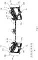
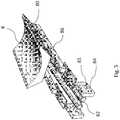
- the walking aid wheelchair 1 according to the second embodimentis shown with reference to figures 10 to 25 .
- the walking aid wheelchair 1 according to the second embodimentis mainly distinguished from that according to the first embodiment by the structure of its movable base 60 and by that of its lifting device 4.
- the walking aid wheelchair 1further comprises a central rear wheel 5 RC which is visible to the eyes.
- figures 24 and 25left 10 G and right 10 D footrests, lower support members 130 which are for example visible to figures 19 to 21 , as well as a locking member 200 of the mobile base which is for example shown in figures 22 and 23 .
- the walking aid wheelchair 1 according to the second embodimentalso comprises a frame 3, front retention members 7 and rear thrust members 8 which are of separate structure respectively from that of the frame 3, front retention 7 and rear thrust members 8 of the walking aid wheelchair 1 according to the first embodiment.
- the backrest 20is rigidly secured to the movable base 60 instead of being secured to the frame 3. It is for example fixed to a rear support element 640 forming part of the frame 600 of the movable base 60.
- the 5 RC center rear center wheelis a smaller size wheel than the left 5 RG and right 5 RD rear wheels. It is similar in size to the 5 FG left and right front wheels. 5 FD . It can in particular pivot relative to the frame 3, to steer the wheelchair 1 more easily.
- Each footrest 10 G , 10 Dis pivotably connected with respect to the frame 3 between a raised position which is shown on figure 11 and a lowered position.
- each footrest 10 G , 10 Dbears against the front upright 32, 34 to which it is connected, so as not to interfere with the walking of the user U.
- the footrestsare oriented l ' towards each other in the transverse direction YY of the wheelchair 1, so that the user U can rest his feet there.
- the frame 3 of the chair according to the second embodimentdiffers from that according to the first embodiment in that it comprises an upper rear support bar 35 H and a bar lower support 35 L , instead of the plate 36 of the chair according to the first embodiment.
- the upper rear support bar 35 H and the lower rear support bar 35 Lextend between the two elongated uprights 32, 34 in a transverse direction YY of the wheelchair 1, by mechanically connecting the two elongated uprights 32, 34 between them. They each have the general shape of a curved tube.
- the upper rear support bar 35 His located in the extension of the upper support bars left 32a and right 34a.
- the 35 H upper rear grab baris located above the 35 L lower rear grab bar.
- the upper rear support bar 35 Hforms a fixed base of the frame 3 with another parallel transverse support bar which serves as a base for the movable seat assembly 6, in particular for the base 60 in its lower position. seat.
- the lower rear support bar 35 Lis located in the extension of the lower left and right support bars 32b 34b.
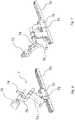
- the position change device 4comprises the first two left arms 41 G , and right 41 D , the first two linear actuators left 44 G and right 44 D of the first left 41 G and right 41 D arms, the two second left arms 42 G and right 42 D , a set of joints 9, as well as two second linear actuators 46 G , 46 D for the second arms 42 G , 42 D.
- the arms 41 G , 41 D , 42 G , 42 D , the mobile base 60 and the frame 3have the general shape of a deformable parallelogram which is deformed, due to the set of joints 9, between the high position of walking and the low sitting position.
- the position changing device 4is configured to move the base 60 relative to the frame 3 between the high running position and the low sitting position. It moves the movable base 60 relative to the frame 3 in a circumferential translational movement between the high running position and the low sitting position.
- the first arms 41 G , 41 Deach extend between the frame 3 and the base 60.
- Each first arm 41 G , 41 Dis connected at its lower end by a lower articulation 92 to one of the upper bars 32a, 34a. It is connected at its upper end by an upper articulation 94 to the mobile base 60.
- the first arms 41 G , 41 Dare parallel to each other. They have a downwardly curved shape near the lower articulation 92 relative to the first arms 41 G , 41 D of the chair according to the first embodiment.
- Each of the first arms 41 G , 41 Dforms an inter-motor type lever which is actuated by one of the first linear actuators 44 G , 44 D.
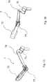
- the second arms 42 G , 42 Deach extend between the frame 3 and the movable base 60.
- Each second arm 42 G , 42 Dis connected at its lower end by a lower articulation 96 to one of the upper bars 32a, 34a .
- Each second arm 42 G , 42 Dis connected at its upper end by an upper articulation 98 to the movable base 60.
- the second arms 42 G , 42 Dare located behind the first arms 41 G , 41 D , being substantially parallel to the first arms 41 G , 41 D. More precisely, the axis of the joints 92, 94 of the second arms are parallel to the axes of the joints 96, 98 of the first arms.
- the second arms 42 G , 42 Dare mutually parallel.
- the second arms 42 G , 42 Dare mutually parallel. They have a downwardly curved shape near the lower articulation 96 relative to the second arm 42 G , 42 D of the chair according to the first embodiment.
- Each second arm 42 G , 42 Dforms an inter-motor type lever which is actuated by one of the second linear actuators 46 G , 46 D.
- Linear actuators 44 G , 44 D , 46 G , 46 Dare each passive linear actuators 44 G , 44 D 46 G , 46 D , that is to say non-motorized linear actuators.
- Each linear actuator 44 G , 44 D , 46 G , 46 Dcomprises an elastic return means which is configured to elastically urge the movable base 60 towards the high position by means of one of the arms 41 G , 41 D , 42 G , 42 D.
- Each of the linear actuators 44 G , 44 D , 46 G , 46 Dincludes a cylinder. More precisely, each linear actuator 46 G , 46 D comprises a gas spring type cylinder.
- the first linear actuators 44 G , 44 Dare each connected by a lower mechanical link 91 to one of the lower bars 32b, 34b of the frame 3 and by an upper mechanical link 93 to one of the first arms 41 G , 41 D.
- Mechanical connection upper 93is located substantially towards the middle of the first arm 41 G , 41 D corresponding.
- Each of the first linear actuators 44 G , 44 Dis configured to urge the movable base 60 towards the high running position by means of one of the first arms 41 G , 41 D. They allow the position changing device 4 to partially support the weight of the user U during the passage from the low position to the high position, while allowing the passage from the high position to the low position using the weight of the user U exerted on the mobile base 60.
- Each of the second linear actuators 46 G , 46 Dis connected by a lower mechanical link 95 to one of the lower bars 32b, 34b of the frame 3 and by an upper mechanical link 97 to one of the second arms 42 G , 42 D.
- the upper mechanical link 97is located substantially towards the middle of the corresponding second arm 42 G , 42 D.
- Each of the second linear actuators 46 G , 46 Dis configured to urge the movable base 60 towards the high running position by means of the corresponding second arm 42 G , 42 D. They allow the position changing device 4 to partially support the weight of the user U during the passage from the low position to the high position, while allowing the passage from the high position to the low position using the weight of user U.
- the joint assembly 9comprises the lower joints 92 of the first arms, the upper joints 94 of the first arms, the lower joints 96 of the second arms, the upper joints 98 of the second arms, the lower mechanical linkage 91 of each first linear actuator 44 G , 44 D , the upper mechanical link 93 of each first linear actuator 44 G , 44 D , the lower mechanical link 95 of each second linear actuator 46 G , 46 D , the upper mechanical link 97 of each second linear actuator 46 G , 46 D.
- the lower joints 92 of the first arms and the upper joints 94 of the first armsare pivot links.
- the lower articulations 92 of the first armsare in front of the upper articulations 94 of the first arms, regardless of the position of the movable base 60 relative to the frame 3.
- the first arms 41 G , 41 Dare inclined upwards towards the rear.
- the movement of the mobile base 60 during the passage from the low seat position to the high walking positionis effected with a movement relative to the frame 3 which is upward and forward, to better reproduce the natural movement of a user U to stand up.
- the distance ratio between the advancement of the pelvis of the user U and the increase in the height of the pelvis of the user U when it accompanies the mobile base 60 in its displacement between its position low seat and its high walking positionis about 4/5.
- the mobile base 60will tend to move rearwardly relative to the frame 3 when it is lowered under the effect of the weight of the user U which is exerted on it.
- the inclination of the first arms 41 G , 41 Dadvances the frame 3 relative to the user when the movable base 60 moves from its high walking position to its low sitting position.
- the lower joints 96 of the second arms and the upper joints 98 of the second armsare pivot links.
- the lower articulations 96 of the second armsare in front of the upper articulations 98 of the second arms, regardless of the position of the movable base 60 relative to the frame.
- the second arms 42 G , 42 Dare inclined upwards and backwards.
- the movement of the mobile base 60 during the passage from the low seat position to the high walking positionis effected with a movement relative to the frame 3 which is upward and forward, to better reproduce the natural movement of a user U to stand up.
- the mobile base 60will tend to move rearwardly relative to the frame 3 when it is lowered under the effect of the weight of the user U which is exerted on it.
- the inclination of the second arms 42 G , 42 Dadvances the frame 3 relative to the user when the movable base 60 moves from its high walking position to its low sitting position.
- the lower articulations 96 of the second armsare behind the corresponding lower articulations 92 of the first arms regardless of the position of the movable base 60 relative to the frame 3.
- the lower articulations 96 of the second armsare in front of the corresponding upper articulations 94 of the first arms, when the movable base 60 is in the low sitting position.
- the upper articulations 98 of the second armsare behind the upper articulations 94 of the first arms regardless of the position of the movable base 60 relative to the frame 3.
- each first linear actuator 44 G , 44 D and the upper mechanical link 93 of each first linear actuator 44 G , 44 Dare pivot links.
- Each first linear actuator 44 G , 44 Dhas a smaller angle with respect to the normal to the first arm 41 G , 41 D to which it is connected by the upper mechanical link 93, close to the upper mechanical link 93, when the movable base 60 is close to its lower seat position only when the movable base 60 is close to its high running position.
- each first linear actuator 44 G , 44 Dtends to exert a greater thrust force on the first arm 41 G , 41 D , when the movable base 60 is close to its lower seat position than when the movable base 60 is close to its high operating position.
- the weight that the user U exerts on the movable base 60 in order to sit downthus remains moderate relative to the stressing force of the base 60 upwards by each first linear actuator 44 G , 44 D.
- This upward bias on each actuator 44 G , 44 Dtherefore does not block the user in the high position.
- the user Ucan then lower himself under the effect of his weight without risk of rearward recoil, when he tends to sit down in the chair 1 or to fall vertically or backwards.
- each first linear actuator 44 G , 44 Dis located behind the lower mechanical link 91 of each first linear actuator 44 G , 44 D , over at least a majority of the stroke of the base movable 60 when it moves relative to the frame 3 between the high position and the low sitting position.
- the inclination of each first linear actuator 44 G , 44 Dis determined in particular for sizing reasons.
- the lever arm exerted by each linear actuator 44 G , 44 D on the first arm 41 G , 41 Dis then satisfactory.
- the lower articulation 91 of each actuator 44 G , 44 Dis not too low relative to the frame 3.
- each first linear actuator 44 G , 44 D and the upper mechanical link 93 of each first linear actuator 44 G , 44 Dare pivot links.
- Each first linear actuator 44 G , 44 Dhas a smaller angle with respect to the normal to the first arm 41 G , 41 D to which it is connected by the upper mechanical link 93, close to the upper mechanical link 93, when the movable base 60 is close to its lower seat position only when the movable base 60 is close to its high running position.
- each first linear actuator 44 G , 44 Dtends to exert a greater thrust force on the first arm 41 G , 41 D , when the movable base 60 is close to its lower seat position than when the movable base 60 is close to its high operating position.
- the weight that the user U exerts on the movable base 60 in order to sit downthus remains moderate relative to the stressing force of the base 60 upwards by each first linear actuator 44 G , 44 D.
- This upward bias on each actuator 44 G , 44 Dtherefore does not block the user in the high position.
- the user Ucan then lower himself under the effect of his weight without risk of rearward recoil, when he tends to sit down in the chair 1 or to fall vertically or backwards.
- each second linear actuator 46 G , 46 Dis located behind the lower mechanical link 95 of each second linear actuator 46 G , 46 D , over at least a majority of the stroke of the base movable 60 when it moves relative to the frame 3 between the high position and the low sitting position.
- the inclination of each second linear actuator 46 G , 46 Dis determined in particular for sizing reasons.
- the lever arm exerted by each second linear actuator 46 G , 46 D on the second arm 42 G , 42 Dis then satisfactory.
- the lower articulation 95 of each second linear actuator 46 G , 46 Dis not too low compared to the frame 3.
- the movable seat assembly 6comprises two lower support members 130 left and right.
- Each lower support member 130is configured to be a rear support for part of the lower limb U ID , U IG of the user U at least in the low sitting position, in particular in the gluteal region of the user U. It is located in front of the saddle 110 in the low seating position.
- Each lower support member 130is also called buttock support in the remainder of the description.
- Each lower bearing member 130comprises a gasket 131 and a gasket support 132 which is covered by the gasket 131.
- Each gasket 131is connected to its gasket support 132 by a guide pin 133 and by a groove 135 which are visible. to the figures 20 and 21 .
- Each lower support member 130is connected by a clip 136 to the frame 3.
- the left pad 131 Gis intended to be in contact with a part of the user's left lower limb U IG , in particular a part of his left buttock or of his left thigh. This is for example a cushion, the guide pin 133 of which projects downward.
- the left trim 131 Ghas a distinct shape from that of the right trim 131 D. Its internal lateral surface is intended to be of substantially complementary shape to the external lateral surface of the left saddle portion 111.
- the right lining 131 Dis intended to be in contact with a part of the user's right lower limb U ID , in particular a part of his right buttock or of his right thigh. This is for example a cushion, the guide pin 133 of which projects downward.
- the internal lateral surface of the right upholstery 131 Dis intended to be of substantially complementary shape to the external lateral surface of the straight saddle portion 112.
- each lower support member 130is intended to be rigidly secured to the frame.
- the lining support 132 of each lower support member 130is connected by screwing to a transverse support bar of the frame 3 which is located in front of the upper rear support bar 35 H of the. chassis 3.
- the trim support 132comprises the groove 135 in its central part.
- each lower support member 130jointly form a lateral adjustment means 134 of the lining 131 G , 131 D relative to the corresponding trim support 132. Due to each lateral adjustment means 134, each trim 131 G , 131 D is at least partly adjustable laterally with respect to the frame 3.
- the mobile base 60 of the chair according to the second embodimentdiffers from that of the chair according to the first embodiment in that it comprises a saddle 110, the backrest 20, a frame 600 and armrests 660.
- the saddle 110comprises a left saddle portion 111, a right saddle portion 112, a central articulation 123 and a saddle base 120.
- Each left 111 or right 112 saddle portionis connected by a groove 145 and by a pin guide 143 to the saddle base 120.
- the saddle base 120is connected to the frame 600.
- the left saddle portion 111is intended to be in contact with a part of the user's left lower limb U IG , in particular a part of his left buttock. This is for example a cushion, the guide pin 143 of which projects downward.
- the left saddle portion 111is of a different shape from that of the right saddle portion 112.
- the internal lateral surface of the left saddle portion 111is intended to be of substantially complementary shape to that of the internal lateral surface of the right portion 112. saddle.
- the right saddle portion 112is intended to be in contact with a part of the user's right lower limb U ID , in particular a part of his right buttock. This is for example a cushion, the guide pin 143 of which projects downward.
- the central articulation 123connects the front end of the left saddle portion 111 to the saddle base 120, in a laterally movable pivot connection.
- the central articulation 123connects the front end of the straight saddle portion 112 to the saddle base 120, in a laterally movable pivot connection.
- the saddle base 120is intended to be connected by the central articulation 123 to the attachment 650 of the frame 600, being tiltable vertically with respect to the attachment 650.
- the saddle base 120includes a groove 145 for each portion of the saddle. saddle 111, 112. These grooves 145 are located on either side of the central part of the saddle base 120.
- Each guide pin 143 and the corresponding groove 145jointly form a lateral adjustment means 142 of one of the saddle portions 111, 112 relative to the saddle base 120. Due to this lateral adjustment means 142, each saddle portion 111, 112 is at least partly adjustable laterally with respect to the frame 600.
- the frame 600 of the movable base 60includes a left support member 610, a right support member 630, a front transverse support member 620, a rear transverse support member 640 and a saddle clip 650.
- the frame 600serves as a support for the saddle 110.
- the frame 600 and the saddle 110replace the lateral support elements 61, 63 and the intermediate support element 62 of the mobile base 60 of the wheelchair 1 according to the first mode of operation. production.
- the first left arm 41 G and the second left arm 42 Gare mechanically connected by the upper articulations 94, 98 to the left support element 610.
- the first right arm 41 D and the second right arm 42 Dare mechanically connected by the upper articulations 94, 98 to the right support element 630.
- the front transverse support member 620extends in the transverse direction YY of the wheelchair from the left support member 610 to the right support member 630, near a middle portion of the left support members 610 and straight 630 in their longitudinal direction.
- the front transverse support element 620has the general shape of a U.
- the saddle attachment 650is rigidly secured to the front transverse support element 620. It is in particular integral with the transverse support element 620.
- the rear transverse support member 640extends in the transverse direction YY of the wheelchair from the left support member 610 to the right support member 630, near the upper joints 98 of the second left arms 42 G and law 42 D.
- the clip 650 for the saddle 110includes a stopper 651 which projects vertically downwards and a connection hole 652 for the saddle 110.
- the connection hole 652is used to connect the saddle 110 to the front support member 620. by a pivot connection around the transverse direction YY, so that the saddle 110 is tiltable in the direction of the height ZZ relative to the frame 600.
- the stop 651serves as a stop for the saddle 110 downwards relative to the frame 600.
- the wheelchair 1comprises two armrests 660 which are each rigidly secured to one of the left 610 and right 630 support elements of the frame.
- Each armrest 660comprises a support arm 662 and an upper trim 661.
- the armrests 660are usable by the user U in the high walking position and also in the low sitting position.
- the support arm 662is in the form of a bracket. Each support arm 662 is connected to the corresponding left support element 610 or right 630, near the upper articulation 98 of the second arms 42 G , 42 D. The upper surface of each support arm 662 is covered by one of the upper fittings 661. Each support arm 662 also serves to connect one of the front retention members 7 to the movable base 60, serving as a base for the support member. retention before 7 matching.
- Each upper trim 661takes for example the form of an oblong cushion.
- each front retention member 7 G , 7 Dcomprises a first articulation 75, an arm 78, a second articulation 77 and the front support element 72.
- the first joint 75connects the arm 78 of the front retention member to one of the armrest support arms 662 660, pivotably about the transverse direction Y-Y.
- the second articulation 77pivotally laterally connects the front support element 72 to the arm 78 of the front retention member.
- the front support element 72is movable laterally around the second articulation 77 between an open position which is shown in figure 17 and at least one closed position such as those shown in figure 15 and at the figure 16 .
- the front support element 72In the open position, the front support element 72 lets the user U sit on the mobile base 60. In the closed position, the front support element 72 retains the user U forwards relative to to the frame 600 of the mobile base 60.
- the front support member 72In the closed position, the front support member 72 is configured to be able to pivot freely relative to the support arm 662 between an upper position and a lower position.
- the front support element 72is shown in the lower position and closed at the figure 15 . It is shown in the upper and closed position at the figure 16 .
- each rear thrust member 8comprises a rear support member 80, a support arm 86, a return means 83, a support 84 and a link member 85.
- Each rear thrust member 8is configured to be in front of the saddle 110 and of the lower support members 130 of the movable base 60 in the low sitting position and in the high running position.
- the rear thrust members 8 G , 8 Dare each configured to urge one of the lower limbs U ID , U IG of the user U forwards during walking. As a result, the walking of the user U is facilitated.
- Each rear support element 80has a concave shape which is intended to match the shape of the lower limb U ID , U IG of the user, in particular of the rear of the thigh of the user U against which the element d 'rear support 80 is supported in the high position and in the low position.
- the return means 83takes the form of a spring, for example a torsion spring. It is configured to urge the rear support element 80 forward, which facilitates the walking of the user U.
- the user U against the return force of each return means 83in particular thanks to its weight. , when the lower limb which is placed on the ground moves back during walking relative to the other of the lower limbs.
- Each of the supports 84is attached to one of the left 610 and right 630 support members.
- the link member 85includes a rod. This is a pivot link configured to pivot the rear support element 80 forwardly relative to the movable base 60.
- the support arm 86connects the rear support element 80 to the support 84. It is configured to pivot around the link member 85. It is located laterally outwardly of the rear support element 80. 'it connects to support 84.
- the walking aid wheelchair 1comprises a locking member 200 of the movable base 60 in the low sitting position.
- the locking member 200comprises a locking bar 202, an articulation 203 of the locking bar, a locking pin 206 and a retaining member 208 on the left side of the walking aid wheelchair 1.
- the locking member 200comprises a locking bar 202, an articulation 203 of the locking bar, a locking pin 206 and a retaining member 208 on the right side of the walking aid wheelchair 1.
- Each locking bar 202is pivotably connected with respect to the frame 3 by the articulation 203 of the locking bar. It comprises a locking arm which forms the body of the locking bar 202, a first notch 205 for housing the locking pin 206, and a second notch 207 for housing the retaining member 208.
- the locking armis designed to be easily accessible by hand by the user and to be movable by hand by the user U when he is in the walking aid wheelchair 1.
- the second notch 207is located behind the first notch 205.
- Each articulation 203 of the locking baris a pivot connection. It connects one of the locking bars 202 to the upper left support bar 32a of the frame 3. It is located near the lower longitudinal end of the locking bar 202.
- Each locking pin 206is rigidly secured to the movable base 60. It is in particular rigidly secured to the left 610 or right 630 support element, from which it protrudes laterally towards the outside of the wheelchair 1. It has by example a rounded outline.
- Each retaining member 208is integral with the second left arm 42 G or right 42 D from which it projects laterally towards the outside of the wheelchair 1. It has, for example, a rounded outline. It serves both as a complementary locking latch to one of the locking pins 206, and to guide the movement of the corresponding locking bar 202 between its upper unlocking position and its lower locking position.
- the locking member 200is movable between a locking position in which the movable base 60 is in the low seating position and an unlocking position in which the movable base is in the high operating position.
- each locking bar 202In the locked position, each locking bar 202 is in the down position and it runs along the upper support bar left 32a or right 34a of the frame.
- Each locking pin 206is engaged in the first notch 205 of one of the locking bars 202.
- Each retaining member 208is engaged in the second notch 207 of one of the locking bars 202.
- each locking bar 202In the unlocked position, each locking bar 202 is in the upper position and it is inclined upwardly relative to the upper left support bar 32a of the frame and to the articulation 203.
- Each locking pin 206is above and in before the first corresponding notch 205.
- Each retainer 208is above and in front of the corresponding second notch 207.
- Each locking barrests on one of the retaining members 208.
- the user Uis seated in the wheelchair 1, the mobile base 60 is in the low sitting position with the locking member 200 locked.
- the position changing device 4is in its folded position which is shown in figure 3 .
- the backrest 20prevents the user U from falling backwards.
- the front retention elements 7prevent the user U from falling forward.
- the control device change of position 4is in an intermediate position between its folded position which is shown in figure 12 and its deployed position which is shown in figure 13 .
- the linear actuators 44 D , 44 G , 46 D , 46 Gurge the movable base 60 towards its high operating position.
- the urging thrust of the linear actuators 44 D , 44 G , 46 D , 46 Gis greatest in the low seat position, it gradually decreases as the angle normal to the arm of each actuator 44 D , 44 G , 46 D , 46 G increases during the lifting of the mobile base.
- the arms 41 D , 41 G , 42 D , 42 Gsupport a tangential force of the user's weight which increases as the mobile base 60 rises to the high running position.
- the position changing device 4partially takes up the weight of the user U over the entire lifting stroke of the movable base 60. It thus helps the user U to get up and stay upright.
- the front retention elements 7prevent the user U from falling forward.
- FIG 11user U is standing.
- the weight of the user Uis partially supported by the position changing device 4 which helps the user U to maintain an upright position.
- Its right U ID and left U IG lower limbsare urged forward by the right 8 R and left 8 G rear thrust members.
- the mobile base 60is in the high running position.
- the position changing device 4is in its deployed position which is shown in figure 13 .
- the front retention elements 7prevent the user U from falling forward.
- the front retention elements 7prevent the user U from falling forward. They also allow him to walk by pulling wheelchair 1 with him, with his hands free.
- the user Ucan use the walking aid wheelchair 1 alone and in safety.
- the position changing device 4tends to limit the speed of its downward movement and to bring the mobile base 60 towards its low sitting position so that he is seated on it, in the position shown in figure 1 or at the figure 10 .
- the position changing device 4can move the movable base 60 relative to the frame 3 from the low seated position to the high walking position, with a risk of falling out of the wheelchair 1 which is reduced.
- the position changing device 4advances the frame 3 relative to the mobile base 60, when the user U wishes to sit down or when the user U tends to fall backwards or vertically.
- the movement of the mobile base 60 during the passage from the low seat position to the high walking positionis effected with a movement relative to the frame 3 which is upward and forward and which reproduces the natural movement of a user U to stand up.
- the position changing device 4partially supports the weight of the user U during the passage from the low position to the high position, while allowing the passage from the high position to the low position using the weight of the user U.
- the wheelchair 1has a dynamic seat, in that the position of the mobile base 60 relative to the frame 3 is variable depending on the weight exerted by the user U on the mobile base 60, including when walking .
- the wheelchair 1requires a moderate effort on the part of the user U to get up, walk and sit down. In particular, it is suitable for re-educating the user U for walking or for keeping him able to walk.
- the assistance provided to the user U by the actuators 44 G , 44 D , 46 G , 46 Dcan be modified to best suit the needs of the user U.
- the movement guidance of the movable base 60 and the stability of the movable base 60 relative to the frame 3are particularly satisfactory thanks to the lifting device 4 and in particular of the plurality of arms 44 G , 44 D , 46 G , 46 D.
- each actuator 44 G , 44 D , 46 G , 46 D of the gas spring typevaries relatively little compared to a motorized cylinder during the stroke of each actuator 44 G , 44 D , 46 G , 46 D , while making the mobile base 60 only partially support the weight of the user U.
- the size of the lifting device 4is reduced.
- the user Ualso benefits from a relatively large walking space. He can easily get in and out of his chair 1.
- the number of wheels 5 RG , 5 RD , 5 FG and 5 FDis variable.
- the wheelchair 1can have a single front wheel or a single rear wheel.
- the structure and shape of the frame 3may vary.
- At least one of the elongated uprights 32, 34takes the form of a plate instead of the lower bars 32b, 34b and the upper bars 32a, 34a.
- the lower bars 32b, 34b and the upper bars 32a, 34acan be mechanically connected to each other at the front and / or at the rear only by the wheel supports 38 G , 38 D , 39 G , 39 D .
- the elongated uprights 32, 34are non-rectilinear, for example by extending in the longitudinal direction X-X by being curved.
- the number of arms 41 G , 41 D , 42 G , 42 D and linear actuators 44 G , 44 Dis variable.
- the wheelchair 1comprises at least a first arm 41 G , 41 D and at least one linear actuator 44 G , 44 D which is mechanically connected to the first arm 41 G , 41 D.
- the linear actuators 44 G , 44 D , 46 G , 46 Dcomprise a spring or other type of elastic return means configured to urge the base towards its high running position.
- the linear actuators 44 G , 44 D , 46 G , 46 Dare motorized.
- the linear actuators 44 G , 44 D , 46 G , 46 Dfor example are controlled by the user to facilitate the lifting of the mobile base 60 and / or the descent of the mobile base 60.
- the wheelchair 1comprises for example a pressure sensor and a calculation unit, to determine a pressure representative of the weight exerted by the user U on the mobile base 60 and to vary the power supplied by each linear actuator 44 G , 44 D , 46 G , 46 D accordingly.
- each actuator 44 G , 44 D , 46 G , 46 Dmay be different from that supplied by at least one other of the actuators 44 G , 44 D , 46 G , 46 D , in particular if the user U requires a greater assistance from actuators 44 G , 44 D , 46 G , 46 D for one of its lower limbs U ID, U IG than for the other.
- linear actuators 44 G , 44 D , 46 G , 46 Dcan be mechanically connected by other types of connection than by pivot connections to the arms 41 G , 41 D , 42 G , 42 D and to the frame 3, for example by ball joints.
- each front retention member 7 G , 7 Dcomprises for example a seat belt.
- the walking aid wheelchair 1comprises a locking member 200 of the movable base 60 in the high walking position.
- the locking member 200comprises a single locking bar 202 which is configured to engage a single locking pin 206 in the locking position. Lock bar 202 is then located on the left or right side of wheelchair 1.
Landscapes
- Health & Medical Sciences (AREA)
- Life Sciences & Earth Sciences (AREA)
- Animal Behavior & Ethology (AREA)
- General Health & Medical Sciences (AREA)
- Public Health (AREA)
- Veterinary Medicine (AREA)
- Epidemiology (AREA)
- Pain & Pain Management (AREA)
- Physical Education & Sports Medicine (AREA)
- Rehabilitation Therapy (AREA)
- Rehabilitation Tools (AREA)
Description
Translated fromFrenchL'invention se rapporte aux dispositifs d'aide à la marche et aux fauteuils roulants, en particulier pour des personnes à mobilité réduite.The invention relates to devices for assisting walking and wheelchairs, in particular for people with reduced mobility.
Des fauteuils roulants aidant à se lever et des déambulateurs à assise mobile sont par exemple connus des documents
Plus généralement, il existe des fauteuils roulants qui aident une personne à mobilité réduite à se lever et à marcher. Certains de ces fauteuils comprennent notamment un châssis, une assise mobile, et un système d'élévation de l'assise.More generally, there are wheelchairs that help a person with reduced mobility to get up and walk. Some of these chairs include a frame, a movable seat, and a seat elevation system.
L'assise mobile est notamment déplacée par rapport au châssis entre une position haute et une position basse d'assise, sous l'effet d'au moins un vérin. En position haute, l'assise mobile est derrière l'utilisateur.The movable seat is in particular moved relative to the frame between a high position and a low seat position, under the effect of at least one jack. In the high position, the mobile seat is behind the user.
Dans un déambulateur à assise mobile tel que celui du document
Certains de ces fauteuils roulants d'aide à la marche ont un espace de marche très réduit. Par ailleurs, certains de ces fauteuils roulants ou déambulateurs à assise mobile n'empêchent pas une personne à mobilité réduite de tomber.Some of these walking assist wheelchairs have very little walking space. In addition, some of these movable seat wheelchairs or walkers do not prevent a person with reduced mobility from falling.
L'invention vise à résoudre au moins partiellement les problèmes rencontrés dans les solutions de l'art antérieur.The invention aims to at least partially resolve the problems encountered in the solutions of the prior art.
A cet égard, l'invention, telle que définie dans la revendication 1, a pour objet un fauteuil roulant d'aide à la marche. Le fauteuil d'aide à la marche comprend un châssis, une embase mobile et un dispositif de changement de position de l'embase.In this regard, the invention, as defined in
L'embase mobile est mobile par rapport au châssis entre une position basse d'assise dans laquelle un utilisateur peut s'asseoir dessus, et une position haute de marche dans laquelle elle est destinée à être au contact de l'utilisateur et au moins partiellement derrière l'utilisateur.The mobile base is movable relative to the frame between a low sitting position in which a user can sit on it, and a high walking position in which it is intended to be in contact with the user and at least partially behind the user.
Le dispositif de changement de position de l'embase est configuré pour déplacer l'embase entre sa position haute et sa position basse. Le dispositif de changement de position comprend au moins un premier bras et un actionneur linéaire. Le premier bras s'étend entre le châssis et l'embase.The base position change device is configured to move the base between its high position and its low position. The position changing device includes at least a first arm and a linear actuator. The first arm extends between the frame and the base.
L'actionneur linéaire est raccordé par une liaison mécanique inférieure au châssis et par une liaison mécanique supérieure au premier bras. L'actionneur linéaire est configuré pour solliciter l'embase mobile vers la position haute par l'intermédiaire du premier bras.The linear actuator is connected by a lower mechanical link to the frame and by an upper mechanical link to the first arm. The linear actuator is configured to urge the movable base towards the high position by means of the first arm.
Selon l'invention, le bras est relié à son extrémité inférieure par une articulation inférieure au châssis et à son extrémité supérieure par une articulation supérieure à l'embase mobile, l'articulation supérieure étant située à l'arrière de l'articulation inférieure sur toute la course de l'embase mobile lorsque l'embase mobile se déplace depuis la position basse jusqu'à la position haute. Le bras forme un levier de type inter-moteur.According to the invention, the arm is connected at its lower end by a lower articulation to the frame and at its upper end by an upper articulation to the movable base, the upper articulation being located at the rear of the lower articulation on the entire travel of the movable base when the movable base moves from the low position to the high position. The arm forms an inter-motor type lever.
Grâce à l'invention, l'utilisateur du fauteuil peut passer de la position basse d'assise à la position haute de marche, avec un risque de chute hors du fauteuil qui est réduit, voire même supprimé. Par ailleurs, le déplacement de l'embase mobile lors du passage de la position basse d'assise à la position haute de marche s'effectue avec un mouvement par rapport au châssis qui est vers le haut et vers l'avant et qui respecte mieux le mouvement naturel d'un utilisateur pour se lever. Le fauteuil roulant requiert un effort modéré de la part de l'utilisateur pour se lever et marcher. En particulier, il est adapté pour rééduquer l'utilisateur à la marche ou pour le maintenir capable de marcher, notamment seul et en sécurité.Thanks to the invention, the user of the chair can move from the low seat position to the high walking position, with a risk of falling out of the chair which is reduced, or even eliminated. Furthermore, the movement of the mobile base during the passage from the low seat position to the high walking position is carried out with a movement relative to the frame which is upwards and forwards and which better respects the natural movement of a user to stand up. The wheelchair requires moderate effort on the part of the user to get up and walk. In particular, it is suitable for re-educating the user for walking or for keeping him able to walk, in particular alone and in safety.
En particulier, le dispositif de changement de position avance le châssis relativement à l'embase, lorsque l'utilisateur souhaite s'assoir ou lorsque l'utilisateur tend à chuter soit vers l'arrière soit sensiblement verticalement.In particular, the position changing device advances the frame relative to the base, when the user wishes to sit down or when the user tends to fall either towards the rear or substantially vertically.
L'actionneur aide l'utilisateur à se lever. Il permet notamment au dispositif de changement de position de supporter au moins partiellement le poids de l'utilisateur lors du passage de la position basse à la position haute, tout en permettant le passage de la position haute à la position basse à l'aide du poids de l'utilisateur exercé sur l'embase mobile.The actuator helps the user to stand up. In particular, it allows the position changing device to at least partially support the weight of the user during the passage from the low position to the high position, while allowing the passage from the high position to the low position using the weight of the user exerted on the mobile base.
Le fauteuil roulant présente une assise dynamique, la position de l'embase mobile relativement au châssis étant variable en fonction du poids exercé par l'utilisateur sur l'embase mobile, notamment lors de la marche.The wheelchair has a dynamic seat, the position of the mobile base relative to the frame being variable according to the weight exerted by the user on the mobile base, in particular when walking.
Du fait notamment du levier inter-moteur, de l'inclinaison du premier bras et éventuellement de l'inclinaison de l'actionneur du premier bras, l'encombrement du dispositif d'élévation est réduit. L'utilisateur bénéficie ainsi d'un espace de marche relativement important.Due in particular to the inter-motor lever, the inclination of the first arm and possibly the inclination of the actuator of the first arm, the size of the lifting device is reduced. The user thus benefits from a relatively large walking space.
Le fauteuil est un fauteuil roulant d'aide à la marche, en ce sens qu'il permet à l'utilisateur, par exemple une personne à mobilité réduite, de marcher plus normalement, notamment avec les pieds au contact du sol. Le fauteuil roulant accompagne l'utilisateur dans son déplacement lorsqu'il marche.The chair is a walking aid wheelchair, in the sense that it allows the user, for example a person with reduced mobility, to walk more normally, in particular with the feet in contact with the ground. The wheelchair accompanies the user in his movement when he walks.
Avantageusement, l'extrémité supérieure du bras est configuré pour former un angle maximum avec l'horizontale dans le sens du cercle trigonométrique en assurant que pour cet angle la valeur absolue du moment normal au bras exercé par l'actionneur soit strictement inférieur à la valeur absolue du moment normal au bras exercé par l'utilisateur lorsqu'il applique la majorité de son poids, de préférence tout son poids sur l'embase mobile.Advantageously, the upper end of the arm is configured to form a maximum angle with the horizontal in the direction of the trigonometric circle, ensuring that for this angle the absolute value of the moment normal to the arm exerted by the actuator is strictly less than the value absolute moment normal to the arm exerted by the user when he applies the majority of his weight, preferably all his weight on the mobile base.
L'augmentation de l'angle de l'actionneur avec la normale au bras avec l'élévation permet d'exercer un effort de poussée plus important en position basse d'assise qu'en position haute de marche. Le poids que l'utilisateur exerce sur l'embase mobile pour s'assoir reste ainsi modéré relativement à l'effort de sollicitation de l'embase vers le haut par l'actionneur. Cette sollicitation vers le haut de l'actionneur ne bloque donc pas l'utilisateur en position haute. Il peut alors s'abaisser sous l'effet de son poids sans risque de recul arrière lorsqu'il tend à s'assoir dans le fauteuil ou à chuter verticalement ou vers l'arrière.The increase in the angle of the actuator with the normal to the arm with the elevation makes it possible to exert a greater pushing force in the low seat position than in the high running position. The weight that the user exerts on the movable base to sit down thus remains moderate relative to the force for urging the base upwards by the actuator. This upward bias on the actuator therefore does not block the user in the high position. He can then lower himself under the effect of his weight without risk of rearward recoil when he tends to sit in the chair or to fall vertically or backwards.
L'invention peut comporter de manière facultative une ou plusieurs des caractéristiques suivantes combinées entre elles ou non.The invention may optionally include one or more of the following features combined or not.
Selon une particularité de réalisation, chaque actionneur linéaire comprend un moyen de rappel élastique configuré pour solliciter élastiquement l'embase mobile vers la position haute par l'intermédiaire du premier bras.According to a particular embodiment, each linear actuator comprises an elastic return means configured to elastically urge the movable base towards the high position by means of the first arm.
L'embase mobile supporte alors partiellement le poids de l'utilisateur lors de la levée, lors de l'assise, et lors de la marche. La position de l'embase mobile relativement au châssis dépend davantage du poids exercé par l'utilisateur sur l'embase mobile. En d'autres termes, le fauteuil roulant est à assise plus dynamique.The mobile base then partially supports the weight of the user when lifting, when sitting down, and when walking. The position of the movable base relative to the frame depends more on the weight exerted by the user on the movable base. In other words, the wheelchair sits more dynamically.
De préférence, chaque actionneur linéaire est passif. Autrement dit, chaque actionneur est non motorisé. Le fauteuil est alors allégé et l'encombrement du fauteuil est réduit par rapport à un fauteuil motorisé, par exemple par un moteur électrique. Par ailleurs, il nécessite une maintenance moins lourde qu'un fauteuil motorisé.Preferably, each linear actuator is passive. In other words, each actuator is non-motorized. The chair is then lightened and the size of the chair is reduced compared to a motorized chair, for example by an electric motor. In addition, it requires less maintenance than a motorized chair.
De préférence, chaque actionneur linéaire comprend un vérin.Preferably, each linear actuator comprises a jack.
De manière très préférée, chaque actionneur linéaire comprend un vérin de type ressort à gaz.Very preferably, each linear actuator comprises a cylinder of the gas spring type.
L'actionneur linéaire de type ressort à gaz n'assiste que partiellement l'utilisateur pour se lever, rester debout et s'assoir. L'intensité de l'effort de levée de l'embase mobile exercé par l'actionneur tend à varier moins durant la course de l'actionneur. L'actionneur aide l'utilisateur à se lever et à s'assoir, tout en étant particulièrement adapté à la rééducation à la marche/ au maintien de la capacité à marcher de l'utilisateur.The gas spring type linear actuator only partially assists the user in getting up, standing and sitting down. The intensity of the lifting force of the movable base exerted by the actuator tends to vary less during the stroke of the actuator. The actuator helps the user to stand up and sit down, while being particularly suitable for gait rehabilitation / maintenance of the user's ability to walk.
Selon une particularité de réalisation, le fauteuil roulant d'aide à la marche comprend au moins deux premiers bras s'étendant chacun entre le châssis et l'embase, et deux actionneurs linéaires qui sont chacun raccordés par une liaison mécanique inférieure au châssis et par une liaison mécanique supérieure à l'un des bras. Les actionneurs linéaires sont configurés pour solliciter l'embase mobile vers la position haute par l'intermédiaire des premiers bras. Les premier bras forment chacun un levier de type inter-moteur.According to one particular embodiment, the walking aid wheelchair comprises at least two first arms each extending between the frame and the base, and two linear actuators which are each connected by a lower mechanical link to the frame and by a mechanical link superior to one of the arms. Linear actuators are configured to bias the movable base towards the position high through the first arms. The first arms each form an inter-motor type lever.
Selon une particularité de réalisation, chaque premier bras est relié à son extrémité inférieure par une articulation inférieure au châssis et à son extrémité supérieure par une articulation supérieure à l'embase mobile. L'articulation supérieure est située à l'arrière de l'articulation inférieure sur toute la course de l'embase mobile lorsque l'embase mobile se déplace depuis la position basse jusqu'à la position haute.According to a particular embodiment, each first arm is connected at its lower end by a lower articulation to the frame and at its upper end by an upper articulation to the movable base. The upper joint is located behind the lower joint over the entire travel of the movable base when the movable base moves from the low position to the high position.
De préférence, liaison mécanique supérieure de chaque actionneur linéaire d'un des premiers bras est située à l'arrière de la liaison mécanique inférieure de cet actionneur linéaire, au moins lorsque l'embase mobile est en position haute.Preferably, the upper mechanical link of each linear actuator of one of the first arms is located at the rear of the lower mechanical link of this linear actuator, at least when the movable base is in the high position.
Selon une particularité de réalisation, le fauteuil roulant d'aide à la marche comprend au moins un deuxième bras qui s'étend entre le châssis et l'embase mobile.According to one particular embodiment, the walking aid wheelchair comprises at least one second arm which extends between the frame and the mobile base.
De préférence, fauteuil roulant d'aide à la marche comprend au moins deux deuxièmes bras qui s'étendent chacun entre le châssis et l'embase mobile.Preferably, the walking aid wheelchair comprises at least two second arms which each extend between the frame and the mobile base.
De préférence, chaque deuxième bras est un bras suiveur qui est entrainé en déplacement relativement au châssis par l'au moins un premier bras.Preferably, each second arm is a follower arm which is driven in movement relative to the frame by the at least one first arm.
En variante et de préférence, le fauteuil roulant comprend en outre un actionneur linéaire par deuxième bras, qui est raccordé par une liaison mécanique inférieure au châssis et par une liaison mécanique supérieure à ce deuxième bras. Cet actionneur linéaire est configuré pour solliciter l'embase mobile vers la position haute par l'intermédiaire du deuxième bras.As a variant and preferably, the wheelchair further comprises one linear actuator per second arm, which is connected by a lower mechanical link to the frame and by an upper mechanical link to this second arm. This linear actuator is configured to urge the movable base towards the high position by means of the second arm.
Selon une particularité de réalisation, les bras sont sensiblement parallèles entre eux. Par exemple, les segments formés par les centres des articulations de chaque bras sont parallèles entre eux.According to a particular embodiment, the arms are substantially parallel to each other. For example, the segments formed by the centers of the joints of each arm are parallel to each other.
Selon une particularité de réalisation, les bras sont raccordés latéralement à l'embase mobile, le dispositif de changement de position est conçu pour que l'utilisateur soit entre les bras, au moins lorsque l'embase mobile est en position haute de marche.According to a particular embodiment, the arms are connected laterally to the mobile base, the position changing device is designed so that the user is between the arms, at least when the mobile base is in the high running position.
De préférence, les bras, l'embase mobile et le châssis ont une forme générale de parallélogramme déformable entre la position haute et la position basse.Preferably, the arms, the movable base and the frame have the general shape of a deformable parallelogram between the high position and the low position.
Selon une particularité de réalisation, le dispositif de changement de position est configuré pour déplacer l'embase mobile par rapport au châssis selon un mouvement de translation circonférentielle entre la position haute de marche et la position basse d'assise.According to one particular embodiment, the position changing device is configured to move the movable base relative to the frame according to a circumferential translational movement between the high running position and the low sitting position.
De préférence, chaque premier bras et/ou chaque deuxième bras est relié à son extrémité inférieure par une liaison pivot au châssis et à son extrémité supérieure par une liaison pivot à l'embase mobile.Preferably, each first arm and / or each second arm is connected at its lower end by a pivot connection to the frame and at its upper end by a pivot connection to the mobile base.
L'embase mobile tend à être mieux guidée et à être plus stable par rapport au châssis. L'utilisateur peut interagir plus facilement avec son environnement, notamment vers l'avant. Il peut entrer et/ou sortir plus facilement de son fauteuil.The movable base tends to be better guided and to be more stable relative to the frame. The user can interact more easily with his environment, especially towards the front. He can get in and / or out of his chair more easily.
De préférence, l'extrémité inférieure et/ou l'extrémité supérieure de chaque premier bras est configuré pour former un angle compris entre 50° et 90° avec l'horizontale dans le sens du cercle trigonométrique, de préférence au maximum 76° lorsque l'embase mobile est en position haute de marche.Preferably, the lower end and / or the upper end of each first arm is configured to form an angle of between 50 ° and 90 ° with the horizontal in the direction of the trigonometric circle, preferably at most 76 ° when the The mobile base is in the high running position.
De préférence, la liaison mécanique inférieure et la liaison mécanique supérieure sont des liaisons pivot.Preferably, the lower mechanical link and the upper mechanical link are pivot links.
Selon une particularité de réalisation, la liaison mécanique supérieure de chaque actionneur linéaire est située à l'arrière de la liaison mécanique inférieure de l'actionneur linéaire, lorsque l'embase mobile est dans au moins une position entre la position haute et la position basse, notamment au moins lorsque l'embase mobile est en position haute.According to one particular embodiment, the upper mechanical link of each linear actuator is located at the rear of the lower mechanical link of the linear actuator, when the mobile base is in at least one position between the high position and the low position. , in particular at least when the movable base is in the high position.
L'inclinaison de chaque actionneur vers le haut vers l'arrière tend par exemple à rapprocher davantage le fauteuil de l'utilisateur lors de la descente de l'embase mobile, et à diminuer le poids à exercer sur l'embase mobile pour la déplacer vers la position basse d'assise, par rapport à un actionneur qui serait incliné vers le haut vers l'avant.The inclination of each actuator upwards towards the rear tends, for example, to bring the chair closer to the user when lowering the mobile base, and to reduce the weight to be exerted on the mobile base to move it. towards the low seat position, relative to an actuator which would be tilted upward forwards.
Avantageusement, la valeur absolue de l'angle entre chaque actionneur linéaire et la normale au bras correspondant en position basse est inférieure à la valeur absolue de l'angle entre cet actionneur linéaire et la normale au bras correspondant en position haute.Advantageously, the absolute value of the angle between each linear actuator and the normal to the corresponding arm in the low position is less than the value absolute of the angle between this linear actuator and the normal to the corresponding arm in the high position.
Selon une particularité de réalisation, l'embase mobile comprend deux éléments de support latéraux et un élément de support intermédiaire situé latéralement entre les deux éléments de support latéraux, chacun des éléments de support latéraux forme avec l'élément de support intermédiaire un logement pour un des membres inférieurs de l'utilisateur en position haute.According to a particular embodiment, the movable base comprises two lateral support elements and an intermediate support element located laterally between the two lateral support elements, each of the lateral support elements forms with the intermediate support element a housing for a lower limbs of the user in the high position.
Selon une particularité de réalisation, l'embase mobile comprend une selle.According to a particular embodiment, the mobile base comprises a saddle.
De préférence, l'embase mobile comprend une base de selle auquel la selle est configurée pour être raccordée de manière détachable.Preferably, the movable base comprises a saddle base to which the saddle is configured to be detachably connected.
Selon une particularité de réalisation, la selle a une position réglable latéralement par rapport au châssis.According to a particular embodiment, the saddle has an adjustable position laterally relative to the frame.
Selon une particularité de réalisation, le fauteuil roulant comprend un organe d'appui inférieur configuré pour être un appui arrière pour une partie de membre inférieur de l'utilisateur au moins en position basse d'assise. L'organe d'appui inférieur est situé en avant de la selle et il est au moins en partie réglable latéralement par rapport au châssis.According to a particular embodiment, the wheelchair comprises a lower support member configured to be a rear support for a part of the lower limb of the user at least in the low sitting position. The lower support member is located in front of the saddle and it is at least partly adjustable laterally with respect to the frame.
De préférence, l'organe d'appui inférieur comprend une garniture qui est réglable latéralement par rapport au châssis.Preferably, the lower support member comprises a lining which is adjustable laterally with respect to the frame.
Selon une particularité de réalisation, l'embase mobile comprend un cadre auquel la selle est raccordée en étant inclinable au moins selon la direction de la hauteur.According to a particular embodiment, the movable base comprises a frame to which the saddle is connected while being tiltable at least in the direction of the height.
Selon une particularité de réalisation, le châssis comprend au moins deux montants longilignes et une base fixe. Les montants longilignes s'étendent au moins partiellement de l'avant vers l'arrière. Les bras et les bras et les actionneurs linéaires sont raccordés aux montants longilignes. La base fixe s'étend entre les deux montants longilignes selon une direction transversale du fauteuil roulant, en reliant mécaniquement les montants longilignes entre eux. L'embase mobile est configurée pour prendre appui sur la base fixe en position basse d'assise.According to a particular embodiment, the frame comprises at least two elongated uprights and a fixed base. The elongated uprights extend at least partially from the front to the rear. The arms and arms and the linear actuators are connected to the elongated uprights. The fixed base extends between the two elongated uprights in a transverse direction of the wheelchair, by mechanically connecting the elongated uprights to each other. The mobile base is configured to rest on the fixed base in the low seat position.
De préférence, les montants longilignes sont rectilignes.Preferably, the elongated uprights are rectilinear.
De préférence, chacun des montants longilignes comprend au moins une barre.Preferably, each of the elongated uprights comprises at least one bar.
De préférence, le châssis comprend un dossier qui est rigidement solidaire de la base fixe et qui s'étend vers le haut depuis la base fixe.Preferably, the frame comprises a backrest which is rigidly integral with the fixed base and which extends upwards from the fixed base.
En variante et de préférence, le fauteuil roulant comprend un dossier qui est rigidement solidaire de l'embase mobile.As a variant and preferably, the wheelchair comprises a backrest which is rigidly secured to the mobile base.
Selon une particularité de réalisation, le fauteuil roulant d'aide à la marche comprend un organe de rétention avant configuré pour retenir l'utilisateur d'aller vers l'avant par rapport au châssis.According to one particular embodiment, the walking aid wheelchair comprises a front retention member configured to retain the user from going forward with respect to the frame.
Selon une particularité de réalisation, l'organe de rétention avant comprend un élément d'appui avant configuré pour prendre appui sur le bassin de l'utilisateur en position haute.According to a particular embodiment, the front retention member comprises a front support element configured to bear on the user's pelvis in the high position.
De préférence, l'élément d'appui avant est un appui iliaque configuré pour prendre appui sur l'épine iliaque antéro-supérieure de l'utilisateur.Preferably, the front support element is an iliac support configured to rest on the anterosuperior iliac spine of the user.
Selon une particularité de réalisation, l'organe de rétention avant est configuré pour guider le fauteuil roulant, au moins lorsque l'embase mobile est en position haute de marche.According to a particular embodiment, the front retention member is configured to guide the wheelchair, at least when the mobile base is in the high running position.
De préférence, l'organe de rétention avant comprend l'élément d'appui avant et une base. L'élément d'appui avant est notamment configuré pour pouvoir pivoter par rapport à la base entre une position supérieure et une position inférieure. Très préférablement, l'élément d'appui avant est configuré pour pivoter par rapport à la base entre une position supérieure lorsque l'embase mobile est en position basse, et une position inférieure lorsque l'embase mobile est en position haute.Preferably, the front retention member comprises the front support member and a base. The front support element is in particular configured to be able to pivot relative to the base between an upper position and a lower position. Very preferably, the front support element is configured to pivot relative to the base between an upper position when the movable base is in the low position, and a lower position when the movable base is in the high position.
De préférence, l'organe de rétention avant comprend un bras de support auquel l'élément d'appui avant est raccordé par une articulation.Preferably, the front retention member comprises a support arm to which the front support member is connected by a hinge.
De préférence, l'élément d'appui avant est mobile latéralement entre une position ouverte dans lequel l'élément d'appui avant laisse l'utilisateur s'assoir sur l'embase mobile et une position fermée dans laquelle il retient l'utilisateur vers l'avant par rapport à l'embase mobile.Preferably, the front support element is movable laterally between an open position in which the front support element allows the user to sit on the mobile base and a closed position in which it retains the user towards the front relative to the mobile base.
Selon une particularité de réalisation, le fauteuil roulant d'aide à la marche comprend un organe arrière de poussée qui est relié de manière mobile à l'embase mobile.According to one particular embodiment, the walking aid wheelchair comprises a rear thrust member which is movably connected to the movable base.
Selon une particularité de réalisation, l'organe arrière de poussée comprend au moins un élément d'appui arrière pour venir en appui contre l'arrière d'un des membres inférieurs de l'utilisateur en position haute, et l'organe arrière de poussée comprend un moyen de rappel configuré pour solliciter l'élément d'appui arrière vers l'avant.According to a particular embodiment, the rear thrust member comprises at least one rear support element to bear against the rear of one of the lower limbs of the user in the high position, and the rear thrust member comprises a return means configured to urge the rear support element forward.
De préférence, l'élément d'appui arrière est pivotable par rapport à l'embase mobile.Preferably, the rear support element is pivotable relative to the movable base.
De manière très préférée, l'élément d'appui arrière est configuré pour avoir un mouvement oscillant par rapport à l'embase mobile en accompagnant le membre inférieur durant la marche.Very preferably, the rear support element is configured to have an oscillating movement relative to the movable base while accompanying the lower limb during walking.
Selon une particularité de réalisation, l'organe arrière de poussée est configuré pour être en regard d'un des logements de l'embase mobile en position haute de marche. L'organe arrière de poussée est configuré pour obturer au moins partiellement le logement en position basse d'assise.According to a particular embodiment, the rear thrust member is configured to be opposite one of the housings of the movable base in the high running position. The rear thrust member is configured to at least partially close the housing in the low seat position.
Selon une autre particularité de réalisation, l'organe arrière de poussée est configuré pour être en avant de la selle, en venant en appui contre l'arrière d'un des membres inférieurs de l'utilisateur en position basse d'assise.According to another particular embodiment, the rear thrust member is configured to be in front of the saddle, resting against the rear of one of the lower limbs of the user in the low sitting position.
Selon une particularité de réalisation, le fauteuil roulant d'aide à la marche comprend un organe de verrouillage de l'embase mobile en position basse d'assise et/ou en position haute de marche.According to one particular embodiment, the walking aid wheelchair comprises a member for locking the movable base in the low sitting position and / or in the high walking position.
De préférence, l'organe de verrouillage comprend au moins une barre de verrouillage raccordée de manière pivotable par rapport au châssis et au moins un pion de verrouillage qui est solidaire de l'embase mobile. La barre de verrouillage engage le pion de verrouillage en position de verrouillage.Preferably, the locking member comprises at least one locking bar pivotably connected with respect to the frame and at least one locking pin which is integral with the movable base. The locking bar engages the locking pin in the locked position.
Très préférablement, l'organe de verrouillage comprend deux barres de verrouillage raccordées chacune de manière pivotable par rapport au châssis et deux pions de verrouillage qui sont chacun solidaires de l'embase mobile. Chaque barre de verrouillage engage un des pions de verrouillage en position de verrouillage.Most preferably, the locking member comprises two locking bars each pivotably connected relative to the frame and two pins. locking which are each integral with the mobile base. Each locking bar engages one of the locking pins in the locking position.
La présente invention sera mieux comprise à la lecture de la description d'exemples de réalisation, donnés à titre purement indicatif et nullement limitatif, en faisant référence aux dessins annexés sur lesquels :
- la
figure 1 est une représentation schématique partielle en perspective d'un fauteuil roulant d'aide à la marche, selon un premier mode de réalisation de l'invention, dans lequel l'embase mobile est en position basse d'assise ; - la
figure 2 est une représentation schématique partielle en perspective du fauteuil roulant d'aide à la marche, dans lequel l'embase est en position haute de marche ; - la
figure 3 est une représentation schématique partielle en perspective de l'embase mobile et du dispositif de changement de position du fauteuil roulant lorsque l'embase est en position basse d'assise ; - la
figure 4 est une représentation schématique partielle en perspective de l'embase mobile et du dispositif de changement de position du fauteuil roulant lorsque l'embase est en position haute de marche ; - la
figure 5 est une représentation schématique partielle en perspective d'un organe arrière de poussée du fauteuil roulant ; - la
figure 6 est une représentation schématique partielle en perspective d'un organe de rétention avant du fauteuil roulant, en position basse d'assise ; - la
figure 7 est une représentation schématique partielle en perspective d'un organe de rétention avant du fauteuil roulant, en position haute de marche ; - la
figure 8 est une représentation schématique partielle en perspective du fauteuil roulant d'aide à la marche, dans lequel l'embase est en position intermédiaire entre la position basse et la position haute ; - la
figure 9 est une représentation schématique partielle en vue arrière du fauteuil roulant d'aide à la marche, dans lequel l'embase est en position intermédiaire ; - la
figure 10 est une représentation schématique partielle en perspective d'un fauteuil roulant d'aide à la marche, selon un deuxième mode de réalisation de l'invention, dans lequel l'embase mobile est en position basse d'assise ; - la
figure 11 une représentation schématique partielle en perspective du fauteuil roulant d'aide à la marche, dans lequel l'embase est en position haute de marche ; - la
figure 12 est une représentation schématique partielle en perspective de l'embase mobile et du dispositif de changement de position du fauteuil roulant lorsque l'embase est en position basse d'assise ; - la
figure 13 est une représentation schématique partielle en perspective de l'embase mobile et du dispositif de changement de position du fauteuil roulant lorsque l'embase est en position haute de marche ; - la
figure 14 est une représentation schématique partielle en perspective d'un organe arrière de poussée du fauteuil roulant ; - la
figure 15 et lafigure 16 sont des représentations schématiques partielles en perspective d'un organe de rétention avant du fauteuil roulant, dans deux position fermée qui sont distinctes par leur inclinaison ; - la
figure 17 est une représentation schématique partielle en perspective d'un organe de rétention avant du fauteuil roulant, en position ouverte ; - la
figure 18 et lafigure 19 sont des représentations schématiques partielles en vue de dessus de l'assise réglable du fauteuil roulant d'aide à la marche, dans deux positions qui sont distinctes par la position latérale de la selle et des appuis inférieurs ; - la
figure 20 et lafigure 21 sont des représentations schématiques partielles en vue de dessous de l'assise réglable du fauteuil roulant d'aide à la marche, dans deux positions distinctes par la position latérale de la selle et des appuis inférieurs ; - la
figure 22 est une représentation schématique partielle en perspective du fauteuil roulant d'aide à la marche, dans lequel l'organe de verrouillage est en position de verrouillage ; - la
figure 23 est une représentation schématique partielle en perspective du fauteuil roulant d'aide à la marche, dans lequel l'organe de verrouillage est en position de déverrouillage ; - la
figure 24 est une représentation schématique partielle en perspective du fauteuil roulant d'aide à la marche, dans lequel l'embase est en position intermédiaire entre la position basse et la position haute ; - la
figure 25 est une représentation schématique partielle en vue arrière du fauteuil roulant d'aide à la marche, dans lequel l'embase est en position intermédiaire entre la position basse et la position haute.
- the
figure 1 is a partial schematic representation in perspective of a wheelchair for assisting walking, according to a first embodiment of the invention, in which the mobile base is in the low sitting position; - the
figure 2 is a partial schematic representation in perspective of the walking aid wheelchair, in which the base is in the high walking position; - the
figure 3 is a partial schematic representation in perspective of the mobile base and of the device for changing the position of the wheelchair when the base is in the low seat position; - the
figure 4 is a partial schematic representation in perspective of the mobile base and of the device for changing the position of the wheelchair when the base is in the high running position; - the
figure 5 is a partial schematic representation in perspective of a rear pushing member of the wheelchair; - the
figure 6 is a partial schematic representation in perspective of a front retention member of the wheelchair, in the low seat position; - the
figure 7 is a partial schematic representation in perspective of a front retention member of the wheelchair, in the high walking position; - the
figure 8 is a partial schematic representation in perspective of the walking aid wheelchair, in which the base is in an intermediate position between the low position and the high position; - the
figure 9 is a partial schematic representation in rear view of the walking aid wheelchair, in which the base is in the intermediate position; - the
figure 10 is a partial schematic representation in perspective of a wheelchair for assisting walking, according to a second embodiment of the invention, in which the mobile base is in the low sitting position; - the
figure 11 a partial schematic representation in perspective of the walking aid wheelchair, in which the base is in the high walking position; - the
figure 12 is a partial schematic representation in perspective of the mobile base and of the device for changing the position of the wheelchair when the base is in the low seat position; - the
figure 13 is a partial schematic representation in perspective of the mobile base and of the device for changing the position of the wheelchair when the base is in the high running position; - the
figure 14 is a partial schematic representation in perspective of a rear pushing member of the wheelchair; - the
figure 15 and thefigure 16 are partial schematic representations in perspective of a front retention member of the wheelchair, in two closed positions which are distinct by their inclination; - the
figure 17 is a partial schematic representation in perspective of a front retention member of the wheelchair, in the open position; - the
figure 18 and thefigure 19 are partial schematic representations in top view of the adjustable seat of the walking aid wheelchair, in two positions which are distinct by the lateral position of the saddle and of the lower supports; - the
figure 20 and thefigure 21 are partial schematic representations in bottom view of the adjustable seat of the walking aid wheelchair, in two different positions by the lateral position of the saddle and the lower supports; - the
figure 22 is a partial schematic representation in perspective of the walking aid wheelchair, in which the locking member is in the locked position; - the
figure 23 is a partial schematic representation in perspective of the walking aid wheelchair, in which the locking member is in the unlocked position; - the
figure 24 is a partial schematic representation in perspective of the walking aid wheelchair, in which the base is in an intermediate position between the low position and the high position; - the
figure 25 is a partial schematic representation in rear view of the walking aid wheelchair, in which the base is in an intermediate position between the low position and the high position.
Des parties identiques, similaires ou équivalentes des différentes figures portent les mêmes références numériques de façon à faciliter le passage d'une figure à l'autre.Identical, similar or equivalent parts of the different figures bear the same numerical references so as to facilitate the passage from one figure to another.
Les
Le fauteuil 1 s'étend selon une direction longitudinale avant-arrière X-X. L'avant du fauteuil correspondant à l'avant de l'utilisateur à la
Le fauteuil 1 s'étend également selon une direction transversale gauche-droite Y-Y. Les sens gauche et droite correspondent respectivement à la gauche et à la droite de l'utilisateur U lorsqu'il est assis dans le fauteuil 1.The
Enfin, le fauteuil 1 s'étend aussi selon une direction de la hauteur Z-Z. Les sens haut et bas correspondent respectivement ceux pour l'utilisateur U lorsqu'il est assis dans le fauteuil 1.Finally, the
Le siège 2 comporte un dossier 20 qui est fixé au châssis 3, et un ensemble d'assise mobile 6 dont fait partie l'embase mobile 60. L'ensemble d'assise mobile 6 est déplaçable par rapport au châssis 3 et sera décrite en détail ci-après.The
L'embase mobile 60 est déplaçable par rapport au châssis 3 entre une position basse d'assise qui est représentée à la
Les roues arrière gauche 5RG et droite 5RD sont des roues de grande taille, classiques pour un fauteuil roulant 1. Les roues avant gauche 5FG et droite 5FD sont de plus petite taille. Elles servent entre autres à diriger le fauteuil roulant 1. Elles peuvent notamment pivoter par rapport au châssis 3, pour permettre à l'utilisateur U de diriger le fauteuil roulant 1 plus facilement.The rear left 5RG and right 5RD wheels are large, standard wheels for a
Le fauteuil roulant 1 est un fauteuil roulant d'aide à la marche dans la mesure où il est destiné à aider une personne à mobilité réduite à se lever et à marcher le plus normalement possible.The
En référence plus spécifiquement aux
Les montants longilignes 32, 34 sont rectilignes et ils s'étendent chacun selon la direction longitudinale X-X de l'avant vers l'arrière, en étant espacés l'un de l'autre selon la direction transversale Y-Y et en étant sensiblement parallèles l'un à l'autre.The
Un des montants 32, 34 est un montant gauche 32. L'autre des montants 32, 34 est un montant droit 34.One of the
Chacun des montants longilignes 32, 34 comprend une barre supérieure de support 32a, 34a et une barre inférieure de support 32b, 34b. La barre inférieure 32b, 34b est parallèle à la barre supérieure 32a, 34a correspondante et au-dessus de celle-ci.Each of the
La barre inférieure 32b, 34b est reliée mécaniquement à la barre supérieure 32a, 34a correspondante par deux barres parallèles avant 33F et arrière 33R. Ces barres parallèles avant 33F et arrière 33R s'étendent chacune verticalement selon la direction de la hauteur Z-Z et elles sont situées sensiblement chacune à une des extrémités longitudinale de la barre supérieure 32a, 34a.The
Les supports de roues avant 38G, 38D sont fixés aux barres avant. Les supports de roues arrière 39G, 39D sont fixés aux barres arrières.
En référence plus spécifiquement à la
Le dossier 20 n'est pas représenté à la
La base fixe 36 a une forme générale de plaque dont la surface supérieure S3 est en regard de la surface inférieure S2 de l'embase mobile 60. Elle comprend deux rebords de logement gauche et droite 37G, 37D qui sont destinés à loger des organes de poussée avant 8 qui font partie de l'ensemble d'assise mobile 6.The fixed
La base fixe 36 sert de socle pour l'ensemble d'assise mobile 6, en particulier pour l'embase 60 dans sa position basse d'assise.The fixed
Le dossier 20 est rigidement solidaire de la base fixe 36 et il s'étend vers le haut depuis la base fixe 36.The
En référence aux
Les bras 41G, 41D, 42G, 42D, l'embase mobile 60 et le châssis 3 forment ensemble un parallélogramme déformable qui se déforme, du fait de l'ensemble d'articulations 9, entre la position haute de marche et la position basse d'assise.The
L'extrémité inférieure et l'extrémité supérieure de chaque premier bras 41G, 41D et de chaque deuxième bras 42G, 42D est configuré pour former un angle compris entre 50° et 90° avec l'horizontale dans le sens du cercle trigonométrique. L'extrémité inférieure et l'extrémité supérieure de chaque premier bras 41G, 41D et de chaque deuxième bras 42G, 42D est notamment configuré pour former un angle d'au plus 76° avec l'horizontale en position haute de marche. Dans le premier mode de réalisation, l'extrémité inférieure et l'extrémité supérieure de chaque premier bras 41G, 41D et de chaque deuxième bras 42G, 42D forme un angle d'environ 67,5° avec l'horizontale.The lower end and the upper end of each
Le dispositif de changement de position 4 est configuré pour déplacer l'embase 60 relativement au châssis 3 entre la position haute de marche et la position basse d'assise. Il déplace l'embase mobile 60 relativement au châssis 3 selon un mouvement de translation circonférentielle entre la position haute de marche et la position basse d'assise.The
Les premiers bras 41G, 41D s'étendent chacun entre le châssis 3 et l'embase 60. Chaque premier bras 41G, 41D est relié à son extrémité inférieure par une articulation inférieure 92 à une des barres supérieures 32a, 34a. Il est relié à son extrémité supérieure par une articulation supérieure 94 à l'embase mobile 60, par exemple sous l'embase 60. Les premiers bras 41G, 41D sont parallèles entre eux.The first arms 41G , 41D each extend between the
Chacun des premiers bras 41G, 41D forme un levier de type inter-moteur qui est actionné par un des actionneurs linéaires 44G, 44D.Each of the first arms 41G , 41D forms an inter-motor type lever which is actuated by one of the linear actuators 44G , 44D.
Les deuxièmes bras 42G, 42D s'étendent chacun entre le châssis 3 et l'embase mobile 60. Chaque deuxième bras 42G, 42D est relié à son extrémité inférieure par une articulation inférieure 96 à une des barres supérieures 32a, 34a. Chaque deuxième bras 42G, 42D est relié à son extrémité supérieure par une articulation supérieure 98 à l'embase mobile 60, par exemple sous l'embase 60.The
Les deuxième bras 42G, 42D sont situés à l'arrière des premiers bras 41G, 41D, en étant sensiblement parallèles aux premier bras 41G, 41D. Plus précisément, l'axe des articulations 92, 94 des deuxièmes bras sont parallèles aux axes des articulations 96, 98 des premiers bras. Les deuxième bras 42G, 42D sont parallèles entre eux.The
Chaque deuxième bras 42G, 42D est un bras suiveur qui est entrainé en déplacement relativement au châssis 3 par un des premiers bras 41G, 41D. Les actionneurs linéaires 44G, 44D sont chacun des actionneurs linéaires 44G, 44D passifs, c'est-à-dire des actionneurs linéaires non motorisés. Par moteur, on entend un système transformant de façon commandée une énergie non-mécanique telle qu'une énergie électrique en une énergie mécanique ou travail.Each
Chacun des actionneurs linéaires 44G, 44D comprend un vérin.Each of the linear actuators 44G , 44D comprises a cylinder.
Les actionneurs linéaires 44G, 44D sont raccordés chacun par une liaison mécanique inférieure 91 à une des barres inférieures 32b, 34b et par une liaison mécanique supérieure 93 à un des premiers bras 41G, 41D. La liaison mécanique supérieure 93 est située sensiblement vers le milieu du premier bras 41G, 41D correspondant.The linear actuators 44G , 44D are each connected by a lower
Chacun des actionneurs linéaires 44G, 44D est configuré pour solliciter l'embase mobile 60 vers la position haute de marche par l'intermédiaire d'un des premiers bras 41G, 41D. Ils permettent au dispositif de changement de position 4 de supporter partiellement le poids de l'utilisateur U lors du passage de la position basse à la position haute, tout en permettant le passage de la position haute à la position basse à l'aide du poids de l'utilisateur U.Each of the linear actuators 44G , 44D is configured to urge the
L'ensemble d'articulations 9 comprend la liaison mécanique inférieure 91, la liaison mécanique supérieure 93, les articulations inférieures 92 des premiers bras, les articulations inférieures 96 des deuxièmes bras, les articulations supérieures 94 des premiers bras, les articulations supérieures 98 des deuxièmes bras.The
Les articulations inférieures 92 des premiers bras et les articulations supérieures 94 des premiers bras sont des liaisons pivots. Les articulations inférieures 92 des premiers bras sont en avant des articulations supérieures 94 des premiers bras, quelle que soit la position de l'embase mobile 60 relativement au châssis 3.The
Autrement dit, les premiers bras 41G, 41D sont inclinés vers le haut vers l'arrière. Le déplacement de l'embase mobile 60 lors du passage de la position basse d'assise à la position haute de marche s'effectue avec un mouvement par rapport au châssis 3 qui est vers le haut et vers l'avant, pour mieux reproduire le mouvement naturel d'un utilisateur U pour se lever. À titre d'exemple, le rapport de distance entre l'avancée du bassin de l'utilisateur U et l'augmentation de la hauteur du bassin de l'utilisateur U lorsqu'il accompagne l'embase mobile 60 dans son déplacement entre sa position basse d'assise et sa position haute de marche est d'environ 4/5. Par ailleurs, l'embase mobile 60 aura tendance à se déplacer vers l'arrière relativement au châssis 3 lorsqu'elle s'abaisse sous l'effet du poids de l'utilisateur U qui est exercé sur elle. En d'autres termes, l'inclinaison des premiers bras 41G, 41D tend à avancer le châssis 3 vers relativement à l'utilisateur lorsque l'embase mobile 60 se déplace de sa position haute de marche vers sa position basse d'assise.In other words, the first arms 41G , 41D are inclined upwards towards the rear. The movement of the
La liaison mécanique inférieure 91 de chaque premier actionneur linéaire 44G, 44D et la liaison mécanique supérieure 93 de chaque premier actionneur linéaire 44G, 44D sont des liaisons pivot. Chaque premier actionneur linéaire 44G, 44D présente un angle plus petit par rapport à la normale au premier bras 41G, 41D auquel il est raccordé par la liaison mécanique supérieure 93, à proximité de la liaison mécanique supérieure 93, lorsque l'embase mobile 60 est proche de sa position basse d'assise que lorsque l'embase mobile 60 est proche de sa position haute de marche.The lower
De ce fait, chaque premier actionneur linéaire 44G, 44D a tendance à exercer un effort de poussée plus important sur le premier bras 41G, 41D, lorsque l'embase mobile 60 est proche de sa position basse d'assise que lorsque l'embase mobile 60 est proche de sa position haute de marche. Le poids que l'utilisateur U exerce sur l'embase mobile 60 pour s'assoir reste ainsi modéré relativement à l'effort de sollicitation de l'embase 60 vers le haut par chaque premier actionneur linéaire 44G, 44D. Cette sollicitation vers le haut de chaque actionneur 44G, 44D ne bloque donc pas l'utilisateur en position haute. L'utilisateur U peut alors s'abaisser sous l'effet de son poids sans risque de recul arrière, lorsqu'il tend à s'assoir dans le fauteuil 1 ou à chuter verticalement ou vers l'arrière.Therefore, each first linear actuator 44G , 44D tends to exert a greater thrust force on the first arm 41G , 41D , when the
La liaison mécanique supérieure 93 de chaque premier actionneur linéaire 44G, 44D est située à l'arrière de la liaison mécanique inférieure 91 de chaque premier actionneur linéaire 44G, 44D, sur au moins une majorité de la course de l'embase mobile 60 lorsqu'elle se déplace relativement au châssis 3 entre la position haute et la position basse d'assise. L'inclinaison de chaque premier actionneur linéaire 44G, 44D est déterminée en particulier pour des raisons de dimensionnement. Le bras de levier exercé par chaque actionneur linéaire 44G, 44D sur le premier bras 41G, 41D est alors satisfaisant. De plus, l'articulation inférieure 91 de chaque actionneur 44G, 44D n'est pas trop basse par rapport au châssis 3.The upper
Les articulations inférieures 96 des deuxièmes bras et les articulations supérieures 98 des deuxièmes bras sont des liaisons pivot. Les articulations inférieures 96 des deuxièmes bras sont en avant des articulations supérieures 98 des deuxièmes bras, quelle que soit la position de l'embase mobile 60 relativement au châssis.The
Autrement dit, les deuxième bras 42G, 42D sont inclinés vers le haut et vers l'arrière. Le déplacement de l'embase mobile 60 lors du passage de la position basse d'assise à la position haute de marche s'effectue avec un mouvement par rapport au châssis 3 qui est vers le haut et vers l'avant, pour mieux reproduire le mouvement naturel d'un utilisateur U pour se lever. Par ailleurs, l'embase mobile 60 aura tendance à se déplacer vers l'arrière relativement au châssis 3 lorsqu'elle s'abaisse sous l'effet du poids de l'utilisateur U qui est exercé sur elle. En d'autres termes, l'inclinaison des deuxième bras 42G, 42D tend à avancer le châssis 3 vers relativement à l'utilisateur lorsque l'embase mobile 60 se déplace de sa position haute de marche vers sa position basse d'assise.In other words, the
Les articulations inférieures 96 des deuxième bras sont en arrière des articulations inférieures 92 correspondantes des premiers bras. Les articulations inférieures 96 des deuxième bras sont en avant des articulations supérieures 94 correspondantes des premiers bras, lorsque l'embase mobile 60 est en position basse d'assise.The
Les articulations supérieures 98 des deuxième bras sont en arrière des articulations supérieures 94 des premiers bras.The
L'ensemble d'assise mobile 6 comprend l'embase mobile 60, deux organes de rétention avant gauche 7G et droit 7D, et deux organes arrières de poussée gauche 8G et droit 8D.The
Les organes de rétention avant 7G, 7D et les organes arrière de poussée 8G, 8D sont chacun reliés mécaniquement de manière mobile par rapport à l'embase mobile 60 qu'ils accompagnent dans son déplacement relativement au châssis 3 entre sa position basse d'assise et sa position haute de marche.The
L'embase mobile 60 comprend une surface supérieure S1 et une surface inférieure S2 qui est opposée à la surface supérieure S1. La surface inférieure S2 vient en appui sur la surface supérieure S3 de la base fixe, en position basse d'assise. Elle est en regard de la surface supérieure S3 de la base fixe, en position haute de marche.The
L'embase mobile 60 comprend deux éléments de support latéraux gauche 61 et droit 63, un élément de support intermédiaire 62 et un élément de support arrière 64. L'embase mobile 60 est mobile en translation circonférentielle par rapport au châssis 3 entre la position basse d'assise et la position haute de marche.The
L'élément de support latéral gauche 61 forme avec l'élément de support intermédiaire 62 un logement 65G pour le membre inférieur gauche UIG de l'utilisateur en position haute. Ce logement 65G est au moins partiellement obturé en position basse d'assise.The left
L'élément de support latéral droit 63 forme avec l'élément de support intermédiaire 62 un logement 65D pour le membre inférieur droit UID de l'utilisateur en position haute. Ce logement 65D est au moins partiellement obturé en position basse d'assise.The right
L'élément de support intermédiaire 62 est situé latéralement entre les deux éléments de support latéraux 61, 63. Il est sensiblement au centre de l'embase mobile 60 selon la direction transversale Y-Y et a notamment une fonction de selle.The
L'élément de support arrière 64 sert de support au fessier de l'utilisateur U en position basse d'assise. Il est situé en arrière de l'utilisateur U en position haute de marche, en délimitant l'arrière de chacun des logements 65G, 65D.The
En référence aux
Les organes de rétention avant 7G, 7D sont chacun configurés pour retenir l'utilisateur U vers l'avant par rapport au châssis 3. Ils permettent également à l'utilisateur U d'entrainer le fauteuil roulant 1.The
La base 70 est destinée à être assemblée fixement à l'embase mobile 60, notamment au niveau d'un des éléments de support latéraux 61, 63 sur lequel elle prend appui. Elle est préférablement reliée mécaniquement de manière détachable à l'embase mobile 60, ce qui rend l'organe de rétention 7G, 7D amovible. Elle sert de support à l'élément d'appui avant 72.The
Le bras 78 relie l'élément d'appui avant 72 à la monture mobile 71. La monture mobile 71 raccorde le bras 78 à l'articulation 73.The
L'élément d'appui avant 72 est un appui iliaque. Il est configuré pour prendre appui sur l'épine iliaque antéro supérieure de l'utilisateur U, en position haute de marche. Il permet à l'utilisateur U d'entrainer le fauteuil roulant 1, sans qu'il ait besoin de ses mains. Il est également configuré pour être à proximité de l'épine iliaque antéro supérieure de l'utilisateur U, en position basse d'assise pour le retenir dans le fauteuil 1.The
Chaque élément d'appui avant 72 est configuré pour se déplacer par rapport à la base 70 entre une position arrière lorsque l'embase est en position basse d'assise, et une position avant lorsque l'embase mobile 60 est en position haute de marche.Each
L'articulation 73 comprend une tige et un ressort de torsion qui sollicite l'élément d'appui avant 72 vers sa position arrière. Elle forme une liaison pivot. Elle est configurée pour faire pivoter l'élément d'appui avant 72 par rapport à la base 70 entre la position arrière et supérieure, qui est représentée à la
L'organe de réglage 74 est réglable en hauteur, en profondeur et latéralement. Il est configuré pour régler la position de l'élément d'appui avant 72 par rapport à la base 70, de manière à ce que l'élément d'appui avant 72 soit en appui sur l'épine iliaque antéro supérieure de l'utilisateur U en position haute de marche.The
La butée 75 est une butée arrière. Elle limite l'amplitude de pivotement de l'élément d'appui avant 72, lorsqu'il est déplacé vers l'arrière par rapport à la base 70.The
En référence aux
Chaque organe arrière de poussée 8 est configuré pour être en regard d'un des logements 65G, 65D de l'embase mobile 60 en position haute de marche. Chaque organe arrière de poussée 8 est configuré pour obturer au moins partiellement le logement 65G, 65D en position basse d'assise.Each
Les organes arrière de poussée 8G, 8D sont chacun configurés pour solliciter un des membres inférieur UID, UIG de l'utilisateur U vers l'avant durant la marche. De ce fait, la marche de l'utilisateur U est facilitée, ce qui est d'autant plus intéressant au regard de l'encombrement et de la masse du fauteuil roulant 1.The
L'élément d'appui arrière 80 a une forme concave qui est destinée à épouser la forme du membre inférieur UID, UIG de l'utilisateur, notamment de la cuisse de l'utilisateur U contre laquelle l'élément d'appui arrière 80 est en appui en position haute et en position basse.The
L'élément d'appui arrière 80 remonte dans le logement 65G, 65D en position basse d'assise, pour l'obturer au moins partiellement et en étant dans son logement 37 de la base fixe 36. L'assise formée par les éléments d'appui arrière 80 et l'embase mobile 60 est alors plus confortable en position basse d'assise.The
L'élément d'appui arrière 80 est pivotable par rapport à l'embase mobile 60, en étant configuré pour avoir un mouvement oscillant selon la direction longitudinale X-X par rapport à l'embase mobile 60, en accompagnant le membre inférieur UID, UIG durant la marche.The
Le moyen de rappel 82 prend la forme d'un ressort, par exemple un ressort hélicoïdal. Il est configuré pour solliciter l'élément d'appui arrière 80 vers l'avant, ce qui facilite la marche de l'utilisateur U. L'utilisateur U contre la force de rappel de chaque moyen de rappel 82, notamment grâce à son poids, lorsque le membre inférieur qui est posé au sol recule lors de la marche relativement à l'autre des membres inférieurs.The return means 82 takes the form of a spring, for example a helical spring. It is configured to urge the
Le support 84 est fixé à la surface inférieure S3 de l'embase mobile 60. L'organe de liaison 85 comprend une tige. Il s'agit d'une liaison pivot configurée pour faire pivoter l'élément d'appui arrière 80 vers l'avant par rapport à l'embase mobile 60.The
Le bras de support 86 relie l'élément d'appui arrière 80 au support 84. Il est configuré pour pivoter autour de l'organe de liaison 85.The
Le passage de la position basse d'assise à la position haute de marche est décrit ci-dessous en référence successivement aux
A la
A la
La poussée de sollicitation des actionneurs linéaires 44D, 44G est la plus forte en position basse d'assise, elle diminue progressivement à mesure que l'angle à la normale au bras de chaque actionneur 44D, 44G augmente au cours de la levée de l'embase mobile. A l'inverse, les bras 41D, 41G, 42D, 42G supportent un effort tangentiel du poids de l'utilisateur de plus en plus important à mesure que l'embase mobile 60 se lève vers la position haute de marche. Le dispositif de changement de position 4 reprend partiellement le poids de l'utilisateur U sur toute la course de levée de l'embase mobile 60. Il aide ainsi l'utilisateur U à se lever et à se maintenir debout. Les éléments de rétention avant 7 empêchent l'utilisateur U de tomber vers l'avant.The urging thrust of the linear actuators 44D , 44G is greatest in the low seating position, it gradually decreases as the angle to the normal to the arm of each actuator 44D , 44G increases during the lifting of the mobile base. Conversely, the
A la
En référence à la
Le fauteuil roulant 1 d'aide à la marche selon le deuxième mode de réalisation est représenté en référence aux
Le fauteuil roulant 1 d'aide à la marche selon le deuxième mode de réalisation se distingue principalement de celui selon le premier mode de réalisation par la structure de son embase mobile 60 et par celle de son dispositif d'élévation 4.The walking
Le fauteuil roulant 1 d'aide à la marche selon le deuxième mode de réalisation comprend en outre une roue arrière centrale 5RC qui est visible aux
Le fauteuil roulant d'aide à la marche 1 selon le deuxième mode de réalisation comprend également un châssis 3, des organes de rétention avant 7 et des organes arrières de poussée 8 qui sont de structure distinctes respectivement de celle du châssis 3, des organes de rétention avant 7 et des organes arrières de poussée 8 du fauteuil roulant d'aide à la marche 1 selon le premier mode de réalisation.The walking
Le dossier 20 est rigidement solidaire de l'embase mobile 60 au lieu d'être solidaire du châssis 3. Il est par exemple fixé à un élément de support arrière 640 faisant partie du cadre 600 de l'embase mobile 60.The
La roue centrale arrière centrale 5RC est une roue de plus petite taille que celle des roues arrières gauche 5RG et droite 5RD. Elle est de taille similaire à celle des roues avant gauche 5FG et droite. 5FD. Elle peut notamment pivoter par rapport au châssis 3, pour diriger le fauteuil roulant 1 plus facilement.The 5 RC center rear center wheel is a smaller size wheel than the left 5RG and right 5RD rear wheels. It is similar in size to the 5FG left and right front wheels. 5FD . It can in particular pivot relative to the
Chaque repose pied 10G, 10D est raccordé de manière pivotable par rapport au châssis 3 entre une position relevée qui est représentée à la
En référence plus spécifiquement aux
La barre d'appui arrière supérieure 35H et la barre d'appui arrière inférieure 35L s'étendent entre les deux montants longilignes 32, 34 selon une direction transversale Y-Y du fauteuil roulant 1, en reliant mécaniquement les deux montants longilignes 32, 34 entre eux. Elles ont chacune une forme générale de tube incurvé.The upper rear support bar 35H and the lower rear support bar 35L extend between the two
La barre d'appui arrière supérieure 35H est située dans le prolongement des barres supérieures de support gauche 32a et droite 34a. La barre d'appui arrière supérieure 35H est située au-dessus de la barre d'appui arrière inférieure 35L. La barre d'appui arrière supérieure 35H forme une base fixe du châssis 3 avec une autre barre d'appui transversale parallèle qui sert de socle pour l'ensemble d'assise mobile 6, en particulier pour l'embase 60 dans sa position basse d'assise.The upper rear support bar 35H is located in the extension of the upper support bars left 32a and right 34a.The 35 H upper rear grab bar is located above the 35L lower rear grab bar. The upper rear support bar 35H forms a fixed base of the
La barre d'appui arrière inférieure 35L est située dans le prolongement des barres inférieures de support 32b gauche et droite 34b.The lower rear support bar 35L is located in the extension of the lower left and right support bars
En référence aux
Les bras 41G, 41D, 42G, 42D, l'embase mobile 60 et le châssis 3 ont une forme générale de parallélogramme déformable qui se déforme, du fait de l'ensemble d'articulations 9, entre la position haute de marche et la position basse d'assise.The
Le dispositif de changement de position 4 est configuré pour déplacer l'embase 60 relativement au châssis 3 entre la position haute de marche et la position basse d'assise. Il déplace l'embase mobile 60 relativement au châssis 3 selon un mouvement de translation circonférentielle entre la position haute de marche et la position basse d'assise.The
Les premiers bras 41G, 41D s'étendent chacun entre le châssis 3 et l'embase 60. Chaque premier bras 41G, 41D est relié à son extrémité inférieure par une articulation inférieure 92 à une des barres supérieures 32a, 34a. Il est relié à son extrémité supérieure par une articulation supérieure 94 à l'embase mobile 60. Les premiers bras 41G, 41D sont parallèles entre eux. Ils ont une forme incurvée vers le bas à proximité de l'articulation inférieure 92 par rapport aux premiers bras 41G, 41D du fauteuil selon le premier mode de réalisation.The first arms 41G , 41D each extend between the
Chacun des premiers bras 41G, 41D forme un levier de type inter-moteur qui est actionné par un des premiers actionneurs linéaires 44G, 44D.Each of the first arms 41G , 41D forms an inter-motor type lever which is actuated by one of the first linear actuators 44G , 44D.
Les deuxièmes bras 42G, 42D s'étendent chacun entre le châssis 3 et l'embase mobile 60. Chaque deuxième bras 42G, 42D est relié à son extrémité inférieure par une articulation inférieure 96 à une des barres supérieures 32a, 34a. Chaque deuxième bras 42G, 42D est relié à son extrémité supérieure par une articulation supérieure 98 à l'embase mobile 60.The
Les deuxième bras 42G, 42D sont situés à l'arrière des premiers bras 41G, 41D, en étant sensiblement parallèles aux premier bras 41G, 41D. Plus précisément, l'axe des articulations 92, 94 des deuxièmes bras sont parallèles aux axes des articulations 96, 98 des premiers bras. Les deuxième bras 42G, 42D sont parallèles entre eux. Les deuxième bras 42G, 42D sont parallèles entre eux. Ils ont une forme incurvée vers le bas à proximité de l'articulation inférieure 96 par rapport aux deuxième bras 42G, 42D du fauteuil selon le premier mode de réalisation.The
Chaque deuxième bras 42G, 42D forme un levier de type inter-moteur qui est actionné par un des deuxièmes actionneurs linéaires 46G, 46D.Each
Les actionneurs linéaires 44G, 44D, 46G, 46D sont chacun des actionneurs linéaires 44G, 44D 46G, 46D passifs, c'est-à-dire des actionneurs linéaires non motorisés.Linear actuators 44G , 44D , 46G , 46D are each passive linear actuators 44G , 44D 46G , 46D , that is to say non-motorized linear actuators.
Chaque actionneur linéaire 44G, 44D, 46G, 46D comprend un moyen de rappel élastique qui est configuré pour solliciter élastiquement l'embase mobile 60 vers la position haute par l'intermédiaire d'un des bras 41G, 41D, 42G, 42D. Chacun des actionneurs linéaires 44G, 44D, 46G, 46D comprend un vérin. Plus précisément, chaque actionneur linéaire 46G, 46D comprend un vérin de type ressort à gaz.Each linear actuator 44G , 44D , 46G , 46D comprises an elastic return means which is configured to elastically urge the
Les premiers actionneurs linéaires 44G, 44D sont raccordés chacun par une liaison mécanique inférieure 91 à une des barres inférieures 32b, 34b du châssis 3 et par une liaison mécanique supérieure 93 à un des premiers bras 41G, 41D. La liaison mécanique supérieure 93 est située sensiblement vers le milieu du premier bras 41G, 41D correspondant.The first linear actuators 44G , 44D are each connected by a lower
Chacun des premiers actionneurs linéaires 44G, 44D est configuré pour solliciter l'embase mobile 60 vers la position haute de marche par l'intermédiaire d'un des premiers bras 41G, 41D. Ils permettent au dispositif de changement de position 4 de supporter partiellement le poids de l'utilisateur U lors du passage de la position basse à la position haute, tout en permettant le passage de la position haute à la position basse à l'aide du poids de l'utilisateur U exercé sur l'embase mobile 60.Each of the first linear actuators 44G , 44D is configured to urge the
Chacun des deuxièmes actionneurs linéaires 46G, 46D est raccordé par une liaison mécanique inférieure 95 à une des barres inférieures 32b, 34b du châssis 3 et par une liaison mécanique supérieure 97 à un des deuxièmes bras 42G, 42D. La liaison mécanique supérieure 97 est située sensiblement vers le milieu du deuxième bras 42G, 42D correspondant.Each of the second linear actuators 46G , 46D is connected by a lower
Chacun des deuxièmes actionneurs linéaires 46G, 46D est configuré pour solliciter l'embase mobile 60 vers la position haute de marche par l'intermédiaire du deuxième bras 42G, 42D correspondant. Ils permettent au dispositif de changement de position 4 de supporter partiellement le poids de l'utilisateur U lors du passage de la position basse à la position haute, tout en permettant le passage de la position haute à la position basse à l'aide du poids de l'utilisateur U.Each of the second linear actuators 46G , 46D is configured to urge the
L'ensemble d'articulations 9 comprend les articulations inférieures 92 des premiers bras, les articulations supérieures 94 des premiers bras, les articulations inférieures 96 des deuxièmes bras, les articulations supérieures 98 des deuxièmes bras, la liaison mécanique inférieure 91 de chaque premier actionneur linéaire 44G, 44D, la liaison mécanique supérieure 93 de chaque premier actionneur linéaire 44G, 44D, la liaison mécanique inférieure 95 de chaque deuxième actionneur linéaire 46G, 46D, la liaison mécanique supérieure 97 de chaque deuxième actionneur linéaire 46G, 46D.The
Les articulations inférieures 92 des premiers bras et les articulations supérieures 94 des premiers bras sont des liaisons pivots. Les articulations inférieures 92 des premiers bras sont en avant des articulations supérieures 94 des premiers bras, quelle que soit la position de l'embase mobile 60 relativement au châssis 3.The
Autrement dit, les premiers bras 41G, 41D sont inclinés vers le haut vers l'arrière. Le déplacement de l'embase mobile 60 lors du passage de la position basse d'assise à la position haute de marche s'effectue avec un mouvement par rapport au châssis 3 qui est vers le haut et vers l'avant, pour mieux reproduire le mouvement naturel d'un utilisateur U pour se lever. À titre d'exemple, le rapport de distance entre l'avancée du bassin de l'utilisateur U et l'augmentation de la hauteur du bassin de l'utilisateur U lorsqu'il accompagne l'embase mobile 60 dans son déplacement entre sa position basse d'assise et sa position haute de marche est d'environ 4/5. Par ailleurs, l'embase mobile 60 aura tendance à se déplacer vers l'arrière relativement au châssis 3 lorsqu'elle s'abaisse sous l'effet du poids de l'utilisateur U qui est exercé sur elle. En d'autres termes, l'inclinaison des premiers bras 41G, 41D avance le châssis 3 relativement à l'utilisateur lorsque l'embase mobile 60 se déplace de sa position haute de marche vers sa position basse d'assise.In other words, the first arms 41G , 41D are inclined upwards towards the rear. The movement of the
Les articulations inférieures 96 des deuxièmes bras et les articulations supérieures 98 des deuxièmes bras sont des liaisons pivot. Les articulations inférieures 96 des deuxièmes bras sont en avant des articulations supérieures 98 des deuxièmes bras, quelle que soit la position de l'embase mobile 60 relativement au châssis.The
Autrement dit, les deuxième bras 42G, 42D sont inclinés vers le haut et vers l'arrière. Le déplacement de l'embase mobile 60 lors du passage de la position basse d'assise à la position haute de marche s'effectue avec un mouvement par rapport au châssis 3 qui est vers le haut et vers l'avant, pour mieux reproduire le mouvement naturel d'un utilisateur U pour se lever. Par ailleurs, l'embase mobile 60 aura tendance à se déplacer vers l'arrière relativement au châssis 3 lorsqu'elle s'abaisse sous l'effet du poids de l'utilisateur U qui est exercé sur elle. En d'autres termes, l'inclinaison des deuxième bras 42G, 42D avance le châssis 3 relativement à l'utilisateur lorsque l'embase mobile 60 se déplace de sa position haute de marche vers sa position basse d'assise.In other words, the
Les articulations inférieures 96 des deuxième bras sont en arrière des articulations inférieures 92 correspondantes des premiers bras quelle que soit la position de l'embase mobile 60 relativement au châssis 3.The
Les articulations inférieures 96 des deuxième bras sont en avant des articulations supérieures 94 correspondantes des premiers bras, lorsque l'embase mobile 60 est en position basse d'assise.The
Les articulations supérieures 98 des deuxième bras sont en arrière des articulations supérieures 94 des premiers bras quelle que soit la position de l'embase mobile 60 relativement au châssis 3.The
La liaison mécanique inférieure 91 de chaque premier actionneur linéaire 44G, 44D et la liaison mécanique supérieure 93 de chaque premier actionneur linéaire 44G, 44D sont des liaisons pivot. Chaque premier actionneur linéaire 44G, 44D présente un angle plus petit par rapport à la normale au premier bras 41G, 41D auquel il est raccordé par la liaison mécanique supérieure 93, à proximité de la liaison mécanique supérieure 93, lorsque l'embase mobile 60 est proche de sa position basse d'assise que lorsque l'embase mobile 60 est proche de sa position haute de marche.The lower
De ce fait, chaque premier actionneur linéaire 44G, 44D a tendance à exercer un effort de poussée plus important sur le premier bras 41G, 41D, lorsque l'embase mobile 60 est proche de sa position basse d'assise que lorsque l'embase mobile 60 est proche de sa position haute de marche. Le poids que l'utilisateur U exerce sur l'embase mobile 60 pour s'assoir reste ainsi modéré relativement à l'effort de sollicitation de l'embase 60 vers le haut par chaque premier actionneur linéaire 44G, 44D. Cette sollicitation vers le haut de chaque actionneur 44G, 44D ne bloque donc pas l'utilisateur en position haute. L'utilisateur U peut alors s'abaisser sous l'effet de son poids sans risque de recul arrière, lorsqu'il tend à s'assoir dans le fauteuil 1 ou à chuter verticalement ou vers l'arrière.Therefore, each first linear actuator 44G , 44D tends to exert a greater thrust force on the first arm 41G , 41D , when the
La liaison mécanique supérieure 93 de chaque premier actionneur linéaire 44G, 44D est située à l'arrière de la liaison mécanique inférieure 91 de chaque premier actionneur linéaire 44G, 44D, sur au moins une majorité de la course de l'embase mobile 60 lorsqu'elle se déplace relativement au châssis 3 entre la position haute et la position basse d'assise. L'inclinaison de chaque premier actionneur linéaire 44G, 44D est déterminée en particulier pour des raisons de dimensionnement. Le bras de levier exercé par chaque actionneur linéaire 44G, 44D sur le premier bras 41G, 41D est alors satisfaisant. De plus, l'articulation inférieure 91 de chaque actionneur 44G, 44D n'est pas trop basse par rapport au châssis 3.The upper
La liaison mécanique inférieure 91 de chaque premier actionneur linéaire 44G, 44D et la liaison mécanique supérieure 93 de chaque premier actionneur linéaire 44G, 44D sont des liaisons pivot. Chaque premier actionneur linéaire 44G, 44D présente un angle plus petit par rapport à la normale au premier bras 41G, 41D auquel il est raccordé par la liaison mécanique supérieure 93, à proximité de la liaison mécanique supérieure 93, lorsque l'embase mobile 60 est proche de sa position basse d'assise que lorsque l'embase mobile 60 est proche de sa position haute de marche.The lower
De ce fait, chaque premier actionneur linéaire 44G, 44D a tendance à exercer un effort de poussée plus important sur le premier bras 41G, 41D, lorsque l'embase mobile 60 est proche de sa position basse d'assise que lorsque l'embase mobile 60 est proche de sa position haute de marche. Le poids que l'utilisateur U exerce sur l'embase mobile 60 pour s'assoir reste ainsi modéré relativement à l'effort de sollicitation de l'embase 60 vers le haut par chaque premier actionneur linéaire 44G, 44D. Cette sollicitation vers le haut de chaque actionneur 44G, 44D ne bloque donc pas l'utilisateur en position haute. L'utilisateur U peut alors s'abaisser sous l'effet de son poids sans risque de recul arrière, lorsqu'il tend à s'assoir dans le fauteuil 1 ou à chuter verticalement ou vers l'arrière.Therefore, each first linear actuator 44G , 44D tends to exert a greater thrust force on the first arm 41G , 41D , when the
La liaison mécanique supérieure 97 de chaque deuxième actionneur linéaire 46G, 46D est située à l'arrière de la liaison mécanique inférieure 95 de chaque deuxième actionneur linéaire 46G, 46D, sur au moins une majorité de la course de l'embase mobile 60 lorsqu'elle se déplace relativement au châssis 3 entre la position haute et la position basse d'assise. L'inclinaison de chaque deuxième actionneur linéaire 46G, 46D est déterminée en particulier pour des raisons de dimensionnement. Le bras de levier exercé par chaque deuxième actionneur linéaire 46G, 46D sur le deuxième bras 42G, 42D est alors satisfaisant. De plus, l'articulation inférieure 95 de chaque deuxième actionneur linéaire 46G, 46D n'est pas trop basse par rapport au châssis 3.The upper
En référence plus spécifiquement aux
Chaque organe d'appui inférieur 130 est configuré pour être un appui arrière pour une partie du membre inférieur UID, UIG de l'utilisateur U au moins en position basse d'assise, notamment dans la région glutéale de l'utilisateur U. Il est situé en avant de la selle 110 en position basse d'assise. Chaque organe d'appui inférieur 130 est également appelé appui fesse dans la suite de la description.Each
Chaque organe d'appui inférieur 130 comprend une garniture 131 et un support de garniture 132 qui est recouvert par la garniture 131. Chaque garniture 131 est raccordée à son support de garniture 132 par un pion de guidage 133 et par une rainure 135 qui sont visibles aux
La garniture gauche 131G est destinée à être en contact d'une partie du membre inférieur gauche UIG de l'utilisateur, notamment une partie de sa fesse gauche ou de sa cuisse gauche. Il s'agit par exemple d'un coussin, dont le pion de guidage 133 fait saillie vers le bas. La garniture gauche 131G est de forme distincte de celle de la garniture droite 131D. Sa surface latérale interne est destinée à être de forme sensiblement complémentaire à la surface latérale externe de la portion gauche 111 de selle.The left pad 131G is intended to be in contact with a partof the user's left lower limb U IG , in particular a part of his left buttock or of his left thigh. This is for example a cushion, the
La garniture droite 131D est destinée à être en contact d'une partie du membre inférieur droite UID de l'utilisateur, notamment une partie de sa fesse droite ou de sa cuisse droite. Il s'agit par exemple d'un coussin, dont le pion de guidage 133 fait saillie vers le bas. La surface latérale interne de la garniture droite 131D est destinée à être de forme sensiblement complémentaire à la surface latérale externe de la portion droite 112 de selle.The right lining 131D is intended to be in contact with a partof the user's right lower limb U ID , in particular a part of his right buttock or of his right thigh. This is for example a cushion, the
Le support 132 de garniture de chaque organe d'appui inférieur 130 est destiné à être rigidement solidaire du châssis. Dans le mode de réalisation représenté, le support 132 de garniture de chaque organe d'appui inférieur 130 est raccordé par vissage à une barre d'appui transversale du châssis 3 qui est située en avant de la barre d'appui arrière supérieure 35H du châssis 3. Le support 132 de garniture comprend la rainure 135 dans sa partie centrale.The
Le pion de guidage 133 et la rainure 135 de chaque organe d'appui inférieur 130 forment conjointement un moyen de réglage latéral 134 de la garniture 131G, 131D relativement au support de garniture 132 correspondant. Du fait de chaque moyen de réglage latéral 134, chaque garniture 131G, 131D est au moins en partie réglable latéralement par rapport au châssis 3.The
En référence plus spécifiquement à la
En référence notamment aux
La portion gauche de selle 111 est destinée à être en contact d'une partie du membre inférieur gauche UIG de l'utilisateur, notamment une partie de sa fesse gauche. Il s'agit par exemple d'un coussin, dont le pion de guidage 143 fait saillie vers le bas. La portion gauche de selle 111 est de forme distincte de celle de la portion droite de selle 112. La surface latérale interne de la portion gauche de selle 111 est destinée à être de forme sensiblement complémentaire de celle la surface latérale interne de la portion droite 112 de selle.The
La portion droite de selle 112 est destinée à être en contact d'une partie du membre inférieur droite UID de l'utilisateur, notamment une partie de sa fesse droite. Il s'agit par exemple d'un coussin, dont le pion de guidage 143 fait saillie vers le bas.The
L'articulation centrale 123 raccorde l'extrémité avant de la portion gauche de selle 111 à la base de selle 120, selon une liaison pivot mobile latéralement. L'articulation centrale 123 raccorde l'extrémité avant de la portion droite de selle 112 à la base de selle 120, selon une liaison pivot mobile latéralement.The
La base de selle 120 est destinée à être raccordée par l'articulation centrale 123 à l'attache 650 du cadre 600, en étant inclinable verticalement par rapport à l'attache 650. La base de selle 120 comprend une rainure 145 pour chaque portion de selle 111, 112. Ces rainures 145 sont situées de part et d'autre de la partie centrale de la base de selle 120.The
Chaque pion de guidage 143 et la rainure 145 correspondante forment conjointement un moyen de réglage latéral 142 d'une des portions de selle 111, 112 relativement à la base de selle 120. Du fait de ce moyen de réglage latéral 142, chaque portion de selle 111, 112 est au moins en partie réglable latéralement par rapport au cadre 600.Each
En référence plus spécifiquement à la
Le premier bras gauche 41G et le deuxième bras gauche 42G sont raccordés mécaniquement par les articulations supérieures 94, 98 à l'élément de support gauche 610.The first left arm 41G and the second
Le premier bras droit 41D et le deuxième bras droit 42D sont raccordés mécaniquement par les articulations supérieures 94, 98 à l'élément de support droit 630.The first right arm 41D and the second
L'élément de support transversal avant 620 s'étend selon la direction transversale Y-Y du fauteuil roulant depuis l'élément de support gauche 610 jusqu'à l'élément de support droit 630, à proximité d'une partie médiane des éléments de support gauche 610 et droit 630 selon leur direction longitudinale. L'élément de support transversal avant 620 a une forme générale de U. L'attache de selle 650 est rigidement solidaire de l'élément de support transversal avant 620. Elle est notamment monobloc avec l'élément de support transversal 620.The front
L'élément de support transversal arrière 640 s'étend selon la direction transversale Y-Y du fauteuil roulant depuis l'élément de support gauche 610 jusqu'à l'élément de support droit 630, à proximité des articulations supérieures 98 des deuxième bras gauche 42G et droit 42D.The rear
L'attache 650 pour la selle 110 comprend une butée 651 qui fait saillie verticalement vers le bas et un orifice 652 de liaison pour la selle 110. L'orifice 652 de liaison sert à raccorder la selle 110 à l'élément de support avant 620 par une liaison pivot autour de la direction transversale Y-Y, pour que la selle 110 soit inclinable selon la direction de la hauteur Z-Z relativement au cadre 600. La butée 651 sert de butée à la selle 110 vers le bas relativement au cadre 600.The
En référence conjointe aux
Le bras de support 662 a une forme de potence. Chaque bras de support 662 est raccordé à l'élément de support gauche 610 ou droit 630 correspondant, à proximité de l'articulation supérieure 98 des deuxièmes bras 42G, 42D. La surface supérieure de chaque bras de support 662 est recouverte par une des garnitures supérieures 661. Chaque bras de support 662 sert également à raccorder un des organes de rétention avant 7 à l'embase mobile 60, en servant de base à l'organe de rétention avant 7 correspondant.The
Chaque garniture supérieure 661 prend par exemple la forme d'un coussin oblong.Each
En référence aux
La première articulation 75 raccorde le bras 78 de l'organe de rétention avant à un des bras de support 662 d'accoudoir 660, de manière pivotante autour de la direction transversale Y-Y.The first joint 75 connects the
La deuxième articulation 77 raccorde de manière pivotante latéralement l'élément d'appui avant 72 au bras 78 de l'organe de rétention avant. L'élément d'appui avant 72 est mobile latéralement autour de la deuxième articulation 77 entre une position ouverte qui est représentée à la
En position ouverte, l'élément d'appui avant 72 laisse l'utilisateur U s'assoir sur l'embase mobile 60. En position fermée, l'élément d'appui avant 72 retient l'utilisateur U vers l'avant par rapport au cadre 600 de l'embase mobile 60.In the open position, the
En position fermée, l'élément d'appui avant 72 est configuré pour pouvoir pivoter librement par rapport au bras de support 662 entre une position supérieure et une position inférieure. L'élément d'appui avant 72 est représenté en position inférieure et fermée à la
En référence plus spécifiquement à la
Chaque organe arrière de poussée 8 est configuré pour être en avant de la selle 110 et des organes d'appui inférieures 130 de l'embase mobile 60 en position basse d'assise et en position haute de marche.Each
Les organes arrière de poussée 8G, 8D sont chacun configurés pour solliciter un des membres inférieur UID, UIG de l'utilisateur U vers l'avant durant la marche. De ce fait, la marche de l'utilisateur U est facilitée.The
Chaque élément d'appui arrière 80 a une forme concave qui est destinée à épouser la forme du membre inférieur UID, UIG de l'utilisateur, notamment de l'arrière de la cuisse de l'utilisateur U contre laquelle l'élément d'appui arrière 80 est en appui en position haute et en position basse.Each
Le moyen de rappel 83 prend la forme d'un ressort, par exemple un ressort de torsion. Il est configuré pour solliciter l'élément d'appui arrière 80 vers l'avant, ce qui facilite la marche de l'utilisateur U. L'utilisateur U contre la force de rappel de chaque moyen de rappel 83, notamment grâce à son poids, lorsque le membre inférieur qui est posé au sol recule lors de la marche relativement à l'autre des membres inférieurs.The return means 83 takes the form of a spring, for example a torsion spring. It is configured to urge the
Chacun des supports 84 est fixé à un des éléments de support gauche 610 et droit 630. L'organe de liaison 85 comprend une tige. Il s'agit d'une liaison pivot configurée pour faire pivoter l'élément d'appui arrière 80 vers l'avant par rapport à l'embase mobile 60.Each of the
Le bras de support 86 relie l'élément d'appui arrière 80 au support 84. Il est configuré pour pivoter autour de l'organe de liaison 85. Il est situé latéralement vers l'extérieur de l'élément d'appui arrière 80 qu'il relie au support 84.The
En référence conjointe à la
L'organe de verrouillage 200 comprend une barre de verrouillage 202, une articulation 203 de la barre de verrouillage, un pion de verrouillage 206 et un organe de retenue 208 du côté gauche du fauteuil roulant 1 d'aide à la marche.The locking
L'organe de verrouillage 200 comprend une barre de verrouillage 202, une articulation 203 de la barre de verrouillage, un pion de verrouillage 206 et un organe de retenue 208 du côté droit du fauteuil roulant 1 d'aide à la marche.The locking
Chaque barre de verrouillage 202 est raccordée de manière pivotable par rapport au châssis 3 par l'articulation 203 de la barre de verrouillage. Elle comprend un bras de verrouillage qui forme le corps de la barre de verrouillage 202, une première encoche 205 de logement du pion de verrouillage 206, et une deuxième encoche 207 de logement de l'organe de retenue 208. Le bras de verrouillage est conçu pour être facilement accessible à la main par l'utilisateur et pour être déplaçable à la main par l'utilisateur U lorsqu'il est dans le fauteuil roulant 1 d'aide à la marche. La deuxième encoche 207 est située en arrière de la première encoche 205.Each locking
Chaque articulation 203 de la barre de de verrouillage est une liaison pivot. Elle raccorde une des barres de verrouillage 202 à la barre supérieure de support gauche 32a du châssis 3. Elle est située à proximité de l'extrémité longitudinale inférieure de la barre de verrouillage 202.Each
Chaque pion de verrouillage 206 est rigidement solidaire de l'embase mobile 60. Il est notamment rigidement solidaire de l'élément de support gauche 610 ou droit 630, dont il est en saillie latéralement vers l'extérieur du fauteuil roulant 1. Il a par exemple un contour arrondi.Each locking
Chaque organe de retenue 208 est solidaire du deuxième bras gauche 42G ou droit 42D dont il est en saillie latéralement vers l'extérieur du fauteuil roulant 1. Il a par exemple un contour arrondi. Il sert à la fois de loquet de verrouillage complémentaire à un des pions de verrouillage 206, et à guider le déplacement de la barre de verrouillage 202 correspondante entre sa position haute de déverrouillage et sa position basse de verrouillage.Each retaining
L'organe de verrouillage 200 est mobile entre une position de verrouillage dans laquelle l'embase mobile 60 est en position basse d'assise et une position de déverrouillage dans laquelle l'embase mobile est en position haute de marche.The locking
En position de verrouillage, chaque barre de verrouillage 202 est en position basse et elle longe la barre supérieure de support gauche 32a ou droite 34a du châssis. Chaque pion de verrouillage 206 est engagé dans la première encoche 205 d'une des barres de verrouillage 202. Chaque organe de retenue 208 est engagé dans la deuxième encoche 207 d'une des barres de verrouillage 202.In the locked position, each locking
En position de déverrouillage, chaque barre de verrouillage 202 est en position haute et elle est inclinée vers le haut relativement à la barre supérieure de support gauche 32a du châssis et à l'articulation 203. Chaque pion de verrouillage 206 est au-dessus et en avant de la première encoche 205 correspondante. Chaque organe de retenue 208 est au-dessus et en avant de la deuxième encoche 207 correspondante. Chaque barre de verrouillage repose sur un des organes de retenue 208.In the unlocked position, each locking
Le passage de la position basse d'assise à la position haute de marche est décrit ci-dessous en référence successivement aux
A la
A la
La poussée de sollicitation des actionneurs linéaires 44D, 44G, 46D, 46G est la plus forte en position basse d'assise, elle diminue progressivement à mesure que l'angle à la normale au bras de chaque actionneur 44D, 44G, 46D, 46G augmente au cours de la levée de l'embase mobile. A l'inverse, les bras 41D, 41G, 42D, 42G supportent un effort tangentiel du poids de l'utilisateur de plus en plus important à mesure que l'embase mobile 60 se lève vers la position haute de marche. Le dispositif de changement de position 4 reprend partiellement le poids de l'utilisateur U sur toute la course de levée de l'embase mobile 60. Il aide ainsi l'utilisateur U à se lever et à se maintenir debout. Les éléments de rétention avant 7 empêchent l'utilisateur U de tomber vers l'avant.The urging thrust of the linear actuators 44D , 44G , 46D , 46G is greatest in the low seat position, it gradually decreases as the angle normal to the arm of each actuator 44D , 44G , 46D , 46G increases during the lifting of the mobile base. Conversely, the
A la
En référence à la
L'utilisateur U peut utiliser le fauteuil roulant 1 d'aide à la marche seul et en sécurité.The user U can use the walking
En cas de chute volontaire ou non de l'utilisateur U vers l'arrière ou verticalement relativement au sol, le dispositif de changement de position 4 tend à limiter la vitesse de son déplacement vers le bas et à amener l'embase mobile 60 vers sa position basse d'assise pour qu'il se retrouve assis dessus, dans la position représentée à la
Le dispositif de changement de position 4 peut déplacer l'embase mobile 60 relativement au châssis 3 de la position basse assise à la position haute de marche, avec un risque de chute hors du fauteuil roulant 1 qui est réduit.The
Le dispositif de changement de position 4 avance le châssis 3 relativement à l'embase mobile 60, lorsque l'utilisateur U souhaite s'assoir ou lorsque l'utilisateur U tend à chuter vers l'arrière ou verticalement.The
De plus, le déplacement de l'embase mobile 60 lors du passage de la position basse d'assise à la position haute de marche s'effectue avec un mouvement par rapport au châssis 3 qui est vers le haut et vers l'avant et qui reproduit le mouvement naturel d'un utilisateur U pour se lever.In addition, the movement of the
Le dispositif de changement de position 4 supporte partiellement le poids de l'utilisateur U lors du passage de la position basse à la position haute, tout en permettant le passage de la position haute à la position basse à l'aide du poids de l'utilisateur U.The
Le fauteuil roulant 1 présente une assise dynamique, en ce sens que la position de l'embase mobile 60 relativement au châssis 3 est variable en fonction du poids exercé par l'utilisateur U sur l'embase mobile 60, y compris lors de la marche.The
Le fauteuil roulant 1 requiert un effort modéré de la part de l'utilisateur U pour se lever, marcher et s'assoir. En particulier, il est adapté pour rééduquer l'utilisateur U à la marche ou pour le maintenir capable de marcher. L'assistance apportée à l'utilisateur U par les actionneurs 44G, 44D, 46G, 46D peut être modifiée pour s'adapter au mieux au besoin de l'utilisateur U.The
Le guidage en déplacement de l'embase mobile 60 et la stabilité de l'embase mobile 60 relativement au châssis 3 sont particulièrement satisfaisants grâce au dispositif d'élévation 4 et notamment de la pluralité de bras 44G, 44D, 46G, 46D.The movement guidance of the
L'intensité de l'effort de levée de l'embase mobile 60 exercé par chaque actionneur 44G, 44D, 46G, 46D de type ressort à gaz varie assez peu par rapport à un vérin motorisé durant la course de chaque actionneur 44G, 44D, 46G, 46D, tout en ne faisant supporter à l'embase mobile 60 que partiellement le poids de l'utilisateur U.The intensity of the lifting force of the
En employant des actionneurs de type ressort à gaz pour 44G, 44D, 46G, 46D la masse du fauteuil roulant 1 est allégée par rapport à un fauteuil roulant d'aide à la marche avec des actionneurs motorisés. Les opérations de maintenance du dispositif d'élévation 4 sont moins lourdes que dans le cas d'un dispositif d'élévation 4 avec des actionneurs motorisés.By employing gas spring type actuators for 44G , 44D , 46G , 46D the mass of
Du fait de la position des bras 41G, 41D,42G, 42D et des actionneurs 44G, 44D, 46G, 46D, l'encombrement du dispositif d'élévation 4 est réduit. L'utilisateur U bénéficie aussi d'un espace de marche relativement important. Il peut entrer et sortir facilement de son fauteuil 1.Due to the position of the
Bien entendu, diverses modifications peuvent être apportées par l'homme du métier à l'invention qui vient d'être décrite sans sortir du cadre de l'exposé de l'invention.Of course, various modifications can be made by those skilled in the art to the invention which has just been described without departing from the scope of the description of the invention.
De manière générale, le nombre de roues 5RG, 5RD, 5FG et 5FD est variable. En particulier, le fauteuil roulant 1 peut comporter une seule roue avant ou une seule roue arrière.In general, the number of wheels 5RG , 5RD , 5FG and 5FD is variable. In particular, the
La structure et la forme du châssis 3 peut varier.The structure and shape of the
Selon une variante de réalisation (non représentée) par exemple, au moins un des montants longilignes 32, 34 prend la forme d'une plaque à la place des barres inférieures 32b, 34b et des barres supérieures 32a, 34a.According to an alternative embodiment (not shown) for example, at least one of the
En variante, les barres inférieures 32b, 34b et les barres supérieures 32a, 34a peuvent être reliées mécaniquement entre elles à l'avant et/ou à l'arrière uniquement par les supports de roues 38G, 38D, 39G, 39D.Alternatively, the
En variante ou en plus, les montants longilignes 32, 34 sont non rectilignes, en s'étendent par exemple selon la direction longitudinale X-X en étant incurvés.As a variant or in addition, the
Le nombre de bras 41G, 41D, 42G, 42D et d'actionneurs linéaires 44G, 44D est variable. De manière générale, le fauteuil roulant 1 comprend au moins un premier bras 41G, 41D et au moins un actionneur linéaire 44G, 44D qui est relié mécaniquement au premier bras 41G, 41D.The number of
En variante, les actionneurs linéaires 44G, 44D, 46G, 46D comprennent un ressort ou un autre type de moyen de rappel élastique configuré pour solliciter l'embase vers sa position haute de marche.As a variant, the linear actuators 44G , 44D , 46G , 46D comprise a spring or other type of elastic return means configured to urge the base towards its high running position.
En variante ou en plus, les actionneurs linéaires 44G, 44D, 46G, 46D sont motorisés. Dans ce cas, les actionneurs linéaires 44G, 44D, 46G, 46D par exemple sont commandés par l'utilisateur pour faciliter la levée de l'embase mobile 60 et/ou la descente de l'embase mobile 60. En variante, le fauteuil roulant 1 comporte par exemple un capteur de pression et une unité de calcul, pour déterminer une pression représentative du poids exercé par l'utilisateur U sur l'embase mobile 60 et pour faire varier la puissance fournie par chaque actionneur linéaire 44G, 44D,46G, 46D en conséquence.As a variant or in addition, the linear actuators 44G , 44D , 46G , 46D are motorized. In this case, the linear actuators 44G , 44D , 46G , 46D for example are controlled by the user to facilitate the lifting of the
La puissance fournie par chaque actionneur 44G, 44D, 46G, 46D peut être différente de celle fournie par au moins un autre des actionneurs 44G, 44D, 46G, 46D, notamment si l'utilisateur U nécessite une assistance plus importante des actionneurs 44G, 44D, 46G, 46D pour un de ses membre inférieur UID, UIG que pour l'autre.The power supplied by each actuator 44G , 44D , 46G , 46D may be different from that supplied by at least one other of the actuators 44G , 44D , 46G , 46D , in particular if the user U requires a greater assistance from actuators 44G , 44D , 46G , 46D for one of its lowerlimbs U ID, UIG than for the other.
En variante ou en plus, les actionneurs linéaires 44G, 44D, 46G, 46D peuvent être reliés mécaniquement par d'autres types de liaison que par des liaisons pivots aux bras 41G, 41D,42G, 42D et au châssis 3, par exemple par des liaisons rotules.As a variant or in addition, the linear actuators 44G , 44D , 46G , 46D can be mechanically connected by other types of connection than by pivot connections to the
La forme et la structure des organes de rétention 7 et des organes de poussée 8 sont variables. En variante ou en plus, chaque organe de rétention avant 7G, 7D comprend par exemple une ceinture de sécurité.The shape and structure of the
En variante ou en plus, le fauteuil roulant 1 d'aide à la marche comprend un organe de verrouillage 200 de l'embase mobile 60 en position haute de marche.As a variant or in addition, the walking
En variante, l'organe de verrouillage 200 comprend une seule barre de verrouillage 202 qui est configurée pour engager un seul pion de verrouillage 206 en position de verrouillage. La barre de verrouillage 202 est alors située sur le côté gauche ou droit du fauteuil roulant 1.As a variant, the locking
Claims (15)
- A walking aid wheelchair (1), comprising:a chassis (3),a movable base plate (60) which is movable relative to the chassis (3) between a low sitting position in which a user (U) can sit thereon, and a high walking position in which it is configured to be in contact with the user (U) and at least partially behind the user (U),a position changing device (4) for the base plate, configured to move the base plate (60) between its high position and its low position,the position changing device (4) comprising at least one first arm (41G, 41D) extending between the chassis (3) and the base plate (60), and a linear actuator (44G, 44D) which is connected through a lower mechanical connection (91) to the chassis (3) and by an upper mechanical connection (93) to the first arm (41G, 41D),
the linear actuator (44G, 44D) being configured to bias the movable base plate (60) to the high position through the first arm (41G, 41D),characterised in that the first arm (41G, 41D) is connected at its lower end through a lower hinge (92) to the chassis (3) and at its upper end through an upper hinge (94) to the movable base plate (60), the upper hinge (94) being located behind the lower hinge (92) over the entire stroke of the movable base plate (60) when the movable base plate (60) moves from the low position up to the high position, andthe first arm (41G, 41D) forming a third class lever. - The walking aid wheelchair (1) according to the preceding claim, wherein each linear actuator (44G, 44D) comprises an elastic return means configured to elastically bias the movable base plate (60) to the high position through the arm (41G, 41D), each linear actuator (44G, 44D) being preferably passive, each linear actuator (44G, 44D) preferably comprising a cylinder, each linear actuator (44G, 44D) comprising more preferably a gas spring loaded type cylinder.
- The walking aid wheelchair (1) according to any of the preceding claims, comprising at least two first arms (41G, 41D) each extending between the chassis (3) and the base plate (60), and two linear actuators (44G, 44D) which are each connected through a lower mechanical connection (91) to the chassis (3) and through an upper mechanical connection (93) to one of the arms (41G, 41D),
the linear actuators (44G, 44D) being configured to bias the movable base plate (60) to the high position through the first arms (41G, 41D),
the arms (41G, 41D) each forming a third class lever,
each first arm (41G, 41D) being connected at its lower end through a lower hinge (92) to the chassis (3) and at its upper end through an upper hinge (94) to the movable base plate (60), the upper hinge (94) being located behind the lower hinge (92) over the entire stroke of the movable base plate (60) when the movable base plate (60) moves from the low position to the high position. - The walking aid wheelchair (1) according to any of the preceding claims, comprising at least one second arm (42G, 42D) which extends between the chassis (3) and the movable base plate (60), preferably two second arms (42G, 42D) which each extend between the chassis (3) and the movable base plate (60),
each second arm (42G, 42D) being preferably a follower arm which is movably driven with respect to the chassis (3) by the at least one first arm (41G, 41D), or
the wheelchair (1) further comprising more preferably a linear actuator (46G, 46D) by second arm (42G, 42D), which is connected by a lower mechanical connection (95) to the chassis (3) and by an upper mechanical connection (97) to this second arm (42G, 42D), this linear actuator (46G, 46D) being configured to bias the movable base plate (60) to the high position through the second arm (42G, 42D). - The walking aid wheelchair (1) according to any of claims 3 to 4, wherein the arms (41G, 41D, 42G, 42D) are substantially parallel to each other,
the arms (41G, 41D, 42G, 42D) being laterally connected to the movable base plate (60), the position changing device (4) being configured so that the user (U) is between the arms (41G, 41D, 42G, 42D), at least when the movable base plate (60) is in the high walking position,
the arms (41G, 41D, 42G, 42D), the movable base plate (60) and the chassis (3) having preferably a generally parallelogram shape deformable between the high position and the low position. - The walking aid wheelchair (1) according to any of the preceding claims, wherein the position changing device (4) is configured to move the movable base plate (60) relative to the chassis (3) in a circumferential translational motion between the high walking position and the low sitting position,
each first arm (41G, 41D) and/or each second arm (42G, 42D) being preferably connected at its lower end by a pivot connection (92, 96) to the chassis (3) and preferably at its upper end by a pivot connection (94, 98) to the movable base plate (60), and/or
the lower end and/or the upper end of each first arm (41G, 41D) being preferably configured to form an angle between 50° and 90° with the horizontal counterclockwise, of preferably at most 76° in the high walking position, and/or
the lower mechanical connection (91) and the upper mechanical connection (93) being preferably pivot connections. - The walking aid wheelchair (1) according to any of the preceding claims, wherein the upper mechanical connection (93, 97) of each linear actuator (44G, 44D, 46G, 46D) is located behind the lower mechanical connection (91, 95) of the linear actuator (44G, 44D, 46G, 46D), when the movable base plate (60) is at least in a position between the high position and the low position, in particular at least when the movable base plate is in the high position,
the absolute value of the angle between each linear actuator (44G, 44D, 46G, 46D) and the normal to the corresponding arm (41G, 41D, 42G, 42D) in the low position being in particular lower than the absolute value of the angle between this linear actuator (44G, 44D, 46G, 46D) and the normal to the corresponding arm (41G, 41D, 42G, 42D) in the high position. - The walking aid wheelchair (1) according to any of the preceding claims, wherein the movable base plate (60) comprises two side support elements (61, 63) and an intermediate support element (62) laterally located between both side support elements (61, 63), each of the side support elements (61, 63) forming with the intermediate support element (64) a housing (65G, 65D) for one of the user's lower limbs (UID, UIG) in the high position, and/or wherein
the movable base plate (60) comprises a saddle (110), and preferably a saddle base (120) to which the saddle (110) is configured to be detachably connected. - The walking aid wheelchair (1) according to the preceding claim, wherein the saddle (110) has a laterally adjustable position relative to the chassis (3), and/or the movable base plate (60) comprises a frame (600) to which the saddle (110) is connected by being tiltable at least along the height direction (Z-Z), and/or
wherein the wheelchair (1) comprises a lower abutment member (130) configured to be a rear abutment for part of the user's lower limb (UID, UIG) at least in the low sitting position, which is located in front of the saddle (110) and which is at least partly laterally adjustable relative to the chassis (3), the lower abutment member (130) preferably comprising at least one fitting (131G, 131D) which is laterally adjustable relative to the chassis (3). - The walking aid wheelchair (1) according to any of the preceding claims, wherein the chassis (3) comprises:at least two slender, preferably rectilinear, posts (32, 34), extending at least partially from front to rear and to which the arms (41G, 41D, 42G, 42D) and the linear actuators (44G, 44D) are connected, each of the slender posts (32, 34) preferably comprising at least one bar (32a, 32b, 34a, 34b), anda fixed base (36, 35H) which extends between both slender posts (32, 34) along a transverse direction (Y-Y) of the wheelchair (1), by mechanically connecting both slender posts (32, 34) to each other,
the movable base plate (60) being configured to abut against the fixed base (36, 35H) in the low sitting position,the chassis (3) preferably comprising a backrest (20) which is rigidly integral with the fixed base (36) and which extends upward from the fixed base (36), or the wheelchair (1) preferably comprising a backrest (20) which is rigidly integral with the movable base plate (60). - The walking aid wheelchair (1) according to any of the preceding claims, comprising a front retaining member (7G, 7D) configured to retain the user (U) from moving forward relative to the chassis (3),
the front retaining member (7G, 7D) comprising a front abutment element (72) configured to abut against the user's (U) pelvis in the high position, the front abutment element (72) being preferably an iliac abutment configured to abut against the user's anterior-superior iliac spine. - The walking aid wheelchair (1) according to the preceding claim, wherein the front retaining member (7G, 7D) is configured to guide the wheelchair (1), at least when the movable base plate (60) is in the high walking position,
wherein the front retaining member (7G, 7D) comprises the front abutment element (72) and preferably a base (70, 662), the front abutment element (72) being in particular configured to be able to pivot relative to the base (70, 662) between an upper position and a lower position, and/or
the front retaining member (7G, 7D) preferably comprises a support arm (78) to which the front abutment element (72) is connected by a hinge (77), such that the front abutment element (72) is laterally movable between an open position in which the front abutment element (72) lets the user (U) sit down on the movable base plate (60) and a closed position in which it retains the user (U) forward relative to the movable base plate (60). - The walking aid wheelchair (1) according to any of the preceding claims, comprising a push rear member (8) which is movably connected to the movable base plate (60),
the push rear member (8) comprising at least one rear abutment element (80) to abut against the rear of one of the user's lower limbs (UID, UIG) in the high position, the push rear member (8) comprising a return means (82, 83) configured to bias the rear abutment element (80) forward,
wherein the rear abutment element (80) is preferably pivotable relative to the movable base plate (60), the rear abutment element (80) being in particular configured to have an oscillating motion relative to the movable base plate (60) while accompanying the lower limb (UID, UIG) in walking. - The walking aid wheelchair (1) according to the preceding claim combined with claim 8, wherein the push rear member (8) is configured to face one of the housings (65G, 65D) of the movable base plate (60) in the high walking position, the push rear member (8) being configured to seal at least partially the housing (65G, 65D) in the low sitting position, or wherein
the push rear member (8) is configured to be in front of the saddle (110) by abutting against the rear of one of the user's lower limbs (UID, UIG) at least in the low sitting position. - The walking aid wheelchair (1) according to one of the preceding claims, comprising a locking member (200) for locking the movable base plate (60) in the low sitting position and/or the high walking position,
the locking member (200) preferably comprising at least one locking bar (202) pivotably connected relative to the chassis (3) and at least one locking pin (206) integral with the movable base plate (60), the locking bar (202) engaging the locking pin (206) in the locking position.
Applications Claiming Priority (2)
| Application Number | Priority Date | Filing Date | Title |
|---|---|---|---|
| FR1751377AFR3063008B1 (en) | 2017-02-21 | 2017-02-21 | WALKING AID WHEELCHAIR |
| PCT/FR2018/050406WO2018154234A1 (en) | 2017-02-21 | 2018-02-21 | Wheelchair for assisting walking |
Publications (2)
| Publication Number | Publication Date |
|---|---|
| EP3585346A1 EP3585346A1 (en) | 2020-01-01 |
| EP3585346B1true EP3585346B1 (en) | 2021-04-21 |
Family
ID=58547727
Family Applications (1)
| Application Number | Title | Priority Date | Filing Date |
|---|---|---|---|
| EP18709680.5AActiveEP3585346B1 (en) | 2017-02-21 | 2018-02-21 | Wheelchair for assisting walking |
Country Status (9)
| Country | Link |
|---|---|
| US (1) | US11471361B2 (en) |
| EP (1) | EP3585346B1 (en) |
| JP (1) | JP7015849B2 (en) |
| CN (1) | CN110461294B (en) |
| CA (1) | CA3053622A1 (en) |
| ES (1) | ES2881264T3 (en) |
| FR (1) | FR3063008B1 (en) |
| SG (1) | SG11201907620WA (en) |
| WO (1) | WO2018154234A1 (en) |
Families Citing this family (12)
| Publication number | Priority date | Publication date | Assignee | Title |
|---|---|---|---|---|
| EP3578154B1 (en)* | 2018-06-05 | 2021-08-04 | Matia Robotics Mekatronik Sistemler AR-GE Mühendislik Yazilim Sanayi ve Ticaret Anonim Sirketi | Indoor and outdoor mobility device system |
| TWI693933B (en)* | 2019-10-07 | 2020-05-21 | 蘇建忠 | Multifunctional wheelchair |
| CN110882136B (en)* | 2019-12-06 | 2024-06-04 | 武汉理工大学 | Multifunctional walking aid device for old people |
| CN111035539B (en)* | 2019-12-31 | 2021-05-18 | 吉林大学 | A walking assistance parallel robot |
| CN216725159U (en) | 2020-05-19 | 2022-06-14 | 移动人生有限责任公司 | Rollable user support device |
| CN112294549B (en)* | 2020-10-29 | 2022-12-30 | 安徽工程大学 | Auxiliary standing seat |
| CN112618182B (en)* | 2020-12-30 | 2023-03-14 | 广东博方众济医疗科技有限公司 | Wheelchair walking aid |
| CN112842724B (en)* | 2021-01-14 | 2023-09-08 | 宁波大学 | An integrated standing and walking assistive device for the elderly |
| KR20230004154A (en) | 2021-06-30 | 2023-01-06 | 현대자동차주식회사 | Wheelchair entering from the rear |
| KR20230125652A (en) | 2022-02-21 | 2023-08-29 | 현대자동차주식회사 | Seating device |
| US11963921B2 (en) | 2022-07-08 | 2024-04-23 | Leo Harden | Convertible walker |
| US11633322B1 (en)* | 2022-07-08 | 2023-04-25 | Leo Harden | Convertible wheelchair |
Family Cites Families (56)
| Publication number | Priority date | Publication date | Assignee | Title |
|---|---|---|---|---|
| SE427895B (en)* | 1979-08-09 | 1983-05-24 | Sven Anders Georg Andreasson | Chair for raising disabled individuals |
| FR2529456B1 (en) | 1982-06-30 | 1985-07-12 | Fralch | LIFT DEVICE FOR WHEELCHAIR AND WHEELCHAIR USING THE SAME |
| NO153913C (en) | 1983-07-08 | 1986-06-18 | Hans Chr Mengshoel | DEVICE AT CHAIR. |
| EP0159562B1 (en) | 1984-04-06 | 1988-12-28 | Levo AG Dottikon | Lifting chair |
| US4884841A (en) | 1988-06-20 | 1989-12-05 | Holley Robert E | Seating assistance device |
| FR2695554B1 (en) | 1992-09-15 | 1994-12-23 | Int Diffusion Consomma | Motorized assistance device, adaptable to a lift chair and lift chair by applying. |
| JPH0866440A (en) | 1994-08-30 | 1996-03-12 | Iura:Kk | Caster walker for physically handicapped person |
| JP3072463B2 (en) | 1995-06-19 | 2000-07-31 | 日進医療器株式会社 | Standing wheelchair |
| JP2813562B2 (en)* | 1995-10-27 | 1998-10-22 | エビスヤ工業株式会社 | Chair |
| JP3032746B2 (en) | 1997-06-24 | 2000-04-17 | アルファー精工株式会社 | wheelchair |
| FR2769830B1 (en) | 1997-10-22 | 2000-02-11 | Int Diffusion Consommateurs Id | IMPROVEMENTS ON ELEVATOR ARMCHAIRS FOR THE DISABLED AND DISABLED |
| JP2000254179A (en) | 1999-03-11 | 2000-09-19 | Meiko Shokai:Kk | Wheelchair |
| JP2000300611A (en)* | 1999-04-19 | 2000-10-31 | Tsubakimoto Chain Co | Standing-up helping chair |
| US6935353B2 (en) | 1999-08-20 | 2005-08-30 | Wade Hawkes | Mobile rehabilitative walker |
| JP2001321404A (en) | 2000-05-17 | 2001-11-20 | Kawamura Cycle:Kk | Wheelchair combined with walking frame |
| US6619681B2 (en)* | 2001-05-16 | 2003-09-16 | Delano Association For The Developmentally Disabled | Dynamic seating and walking wheelchair |
| JP2003325262A (en)* | 2002-05-14 | 2003-11-18 | Koyo Giken Kk | Elevating legless chair |
| US7669863B2 (en)* | 2006-01-24 | 2010-03-02 | Rensselaer Polytechnic Institute | Walker with lift-assisting seat assembly |
| JP2007244817A (en) | 2006-03-15 | 2007-09-27 | Tc Lab:Kk | Electric wheelchair with elevating function |
| GB0610313D0 (en) | 2006-05-24 | 2006-07-05 | Firth Charles B | Wheelchair with elevating seat |
| FR2901997B1 (en)* | 2006-06-07 | 2009-05-15 | Lifestand Vivre Debout Soc A R | VERTICALIZING SEAT WITH TILTING BACKREST |
| CH712922B1 (en) | 2007-07-13 | 2018-03-15 | Levo Ag Wohlen | Erecting unit for raising wheelchairs and therapy devices. |
| US9649243B2 (en) | 2008-01-07 | 2017-05-16 | Lite Run, Inc. | Body lift-assist walker device |
| JP2009233090A (en) | 2008-03-27 | 2009-10-15 | Ryobi Ltd | Gripper of wheelchair with elevating seat, which is used for standing up |
| US8104835B2 (en)* | 2008-07-08 | 2012-01-31 | Invacare Corp. | Standing frame with supine mode |
| CN201248811Y (en) | 2008-08-18 | 2009-06-03 | 马廷凯 | Walk assisting wheelchair |
| KR101043207B1 (en) | 2008-10-22 | 2011-06-22 | 서강대학교산학협력단 | Wheelchair Walking Assistant Robot |
| JP5563570B2 (en)* | 2009-06-01 | 2014-07-30 | 株式会社テムザック | Transfer / Moving device |
| DE102009050734B4 (en) | 2009-10-26 | 2013-10-10 | Anton Skrivanek | Mobile multi-therapy trolley |
| US8151812B2 (en)* | 2010-07-02 | 2012-04-10 | Eli Razon | Sit down and stand up walker with seat assembly |
| EP2618796A1 (en)* | 2010-09-23 | 2013-07-31 | Hazeleger Investments B.V. | Assist device with standing aid for adding to a wheelchair, a wheelchair integrated with such an assist device and method for manufacture thereof |
| JP5240626B2 (en) | 2010-10-19 | 2013-07-17 | 孟雄 小田 | Lifting seated wheelchair |
| KR101356520B1 (en) | 2011-02-28 | 2014-01-29 | 엘지전자 주식회사 | Walking assistance system |
| WO2013041972A2 (en) | 2011-09-20 | 2013-03-28 | Maurer Balz | Stabilized raising wheelchair |
| JP5312550B2 (en) | 2011-10-18 | 2013-10-09 | タマチ工業株式会社 | Walking aid chair |
| CN202313991U (en) | 2011-11-29 | 2012-07-11 | 厦门优尔电器有限公司 | Improved wheelchair capable of assisting old person to walk |
| JP5876358B2 (en) | 2012-03-30 | 2016-03-02 | 国立大学法人九州大学 | Walking exercise aid |
| CN102846440A (en) | 2012-09-28 | 2013-01-02 | 昆山市工业技术研究院有限责任公司 | Multi-functional standing and sitting device for walker wheelchair |
| ES2459866B1 (en) | 2012-10-11 | 2015-02-17 | Consejo Superior De Investigaciones Científicas (Csic) | WALKER WITH ASSISTANCE MECHANISM IN SURVEY OPERATIONS AND SITTING OF A USER. |
| CN103156739B (en) | 2013-04-08 | 2016-03-30 | 昆山安明泰机电科技有限公司 | Wheelchair Qi Zuo mechanism and comprise the wheelchair of this mechanism |
| WO2014175707A1 (en) | 2013-04-25 | 2014-10-30 | 세종대학교산학협력단 | Variable seating unit, auxiliary walking unit, and wheelchair comprising same |
| US20150090308A1 (en)* | 2013-09-27 | 2015-04-02 | Remco Bos | Walker assembly and method of use to assist a seated person to rise to a standing position |
| US8944458B1 (en) | 2014-01-05 | 2015-02-03 | Marcio C. Ferez | Adjustable walker with sitting assembly |
| US20150202102A1 (en) | 2014-01-20 | 2015-07-23 | Anita Dunham | Wheelchair with Automatic Seat Lift Mechanism |
| CN103767855A (en) | 2014-02-21 | 2014-05-07 | 哈尔滨理工大学 | Sitting and standing rehabilitation system having gravity compensating function |
| CL2014001511A1 (en) | 2014-06-09 | 2015-08-14 | Juan Pablo Rodriguez Vicentini | Wheelchair for standing with ergonomic lifting mechanism from the base of the seat, comprises a chassis, a power transmission bar, an oblique bar, an axle, a mechanism or element of any nature for lifting the seat, a piston, a base, a backrest support plate and a footrest. |
| MX2017000479A (en)* | 2014-07-14 | 2017-09-01 | Exokinetics Inc | Elevating walker chair. |
| USD740721S1 (en) | 2014-07-22 | 2015-10-13 | Jimmy Wayne Shaw | Walker |
| CN104382702B (en) | 2014-10-30 | 2016-08-17 | 合肥工业大学 | A kind of Multifunction restoring wheelchair |
| US9737448B2 (en) | 2014-11-01 | 2017-08-22 | Jerome C. Farmer | Elevating manual wheelchair |
| US20160270988A1 (en)* | 2015-03-18 | 2016-09-22 | Challenging Solutions, Inc. | Modularized mobility device |
| SG10201502867QA (en) | 2015-04-10 | 2016-11-29 | Xentiq Partners Pte Ltd | Seat device and assistive walker device comprising the seat device |
| US9820901B2 (en) | 2015-05-13 | 2017-11-21 | Adam Brown | Patient assistance and rehabilitation device and method of use |
| GB2538953B (en) | 2015-05-28 | 2021-02-17 | Meiban Int Pte Ltd | Smart elderly walker |
| CN104856843B (en) | 2015-06-03 | 2017-03-01 | 天津科技大学 | Coordinate extremity type rehabilitation go-cart |
| CN205459437U (en)* | 2016-01-29 | 2016-08-17 | 北京动力京工科技有限公司 | Electronic wheelchair of intelligence rehabilitation training |
- 2017
- 2017-02-21FRFR1751377Apatent/FR3063008B1/enactiveActive
- 2018
- 2018-02-21CACA3053622Apatent/CA3053622A1/enactivePending
- 2018-02-21CNCN201880013085.3Apatent/CN110461294B/enactiveActive
- 2018-02-21JPJP2019565989Apatent/JP7015849B2/enactiveActive
- 2018-02-21EPEP18709680.5Apatent/EP3585346B1/enactiveActive
- 2018-02-21SGSG11201907620WApatent/SG11201907620WA/enunknown
- 2018-02-21ESES18709680Tpatent/ES2881264T3/enactiveActive
- 2018-02-21USUS16/486,384patent/US11471361B2/enactiveActive
- 2018-02-21WOPCT/FR2018/050406patent/WO2018154234A1/ennot_activeCeased
Non-Patent Citations (1)
| Title |
|---|
| None* |
Also Published As
| Publication number | Publication date |
|---|---|
| FR3063008A1 (en) | 2018-08-24 |
| EP3585346A1 (en) | 2020-01-01 |
| WO2018154234A1 (en) | 2018-08-30 |
| SG11201907620WA (en) | 2019-09-27 |
| JP2020508826A (en) | 2020-03-26 |
| US20200237602A1 (en) | 2020-07-30 |
| CA3053622A1 (en) | 2018-08-30 |
| CN110461294B (en) | 2021-07-16 |
| JP7015849B2 (en) | 2022-02-03 |
| CN110461294A (en) | 2019-11-15 |
| ES2881264T3 (en) | 2021-11-29 |
| FR3063008B1 (en) | 2022-03-18 |
| US11471361B2 (en) | 2022-10-18 |
Similar Documents
| Publication | Publication Date | Title |
|---|---|---|
| EP3585346B1 (en) | Wheelchair for assisting walking | |
| EP2004124B1 (en) | Multi-position chair for handicapped user | |
| EP1864637B1 (en) | Standing seat with reclining back | |
| WO1995025497A1 (en) | Lifting device for a stand-up wheelchair and wheelchair using same | |
| FR2676630A1 (en) | INTERCONNECTION MECHANISM FOR SUPPORTING A SEAT AND A FOLDER OF A CHAIR. | |
| WO2016001451A1 (en) | Vehicle including a hinged chair with a stand assist mechanism | |
| EP0274330A1 (en) | Standing-up and sitting-down device, especially for chairs or fixed or removable seats | |
| FR2529456A1 (en) | Elevating device for a wheelchair and wheelchair making use thereof | |
| EP1489945B1 (en) | Ergonomic seating module and seat fitted with said module | |
| EP0146660B1 (en) | Stand-up apparatus for a wheel chair, and wheel chair provided therewith | |
| EP1488770B1 (en) | Stand-up chair with self-modifying tilting of the backrest | |
| EP3097898A1 (en) | Hospital chair provided with a system to help patients sit and stand back up | |
| FR2965716A1 (en) | Wheel chair for enabling e.g. muscular dystrophy affected person, e.g. to move to ground depending on occupation, has actuator adjusting angular position of armrests around axis of articulation with respect to backrest | |
| WO2018104595A1 (en) | Anterior support device for the lower limbs | |
| EP0959860A1 (en) | Accessory for supporting a wheelchair in a stable reclined position | |
| WO2002047513A1 (en) | Multiple-position armchair | |
| FR3106492A1 (en) | Wheelchair | |
| FR3019019A1 (en) | BODY-HOLDING DEVICE IN STAND-UP POSITION OR SITTING-STANDING OR SITTING | |
| FR3079119A1 (en) | ASSEMBLY DEVICE FOR ASSEMBLY OF THE SEAT POSITION AT THE STAND POSITION, AND REVERSE, MOBILITY PLATFORM FOR A SEAT COMPRISING SUCH A DEVICE, AND A ROLLING SEAT | |
| FR2619495A1 (en) | LONG CHAIR | |
| FR3151196A3 (en) | reversing device | |
| FR2639807A1 (en) | Chair with pivoting seat | |
| FR3017787A1 (en) | ERGONOMIC DEVICE FOR HOLDING IN STAND-UP OR STAND-UP POSITION | |
| FR2883727A1 (en) | Mobility impaired user's e.g. aged person, seating and raising assisting device for use on e.g. armchair seat, has armchair chassis acting as air reservoir, connected to pneumatic cylinder in sealed manner and including pressurization valve | |
| FR3005850A1 (en) | ARMCHAIR FOR HANDICAPPING OR INVALID WITH INCLINABLE SEAT STRUCTURE |
Legal Events
| Date | Code | Title | Description |
|---|---|---|---|
| STAA | Information on the status of an ep patent application or granted ep patent | Free format text:STATUS: UNKNOWN | |
| STAA | Information on the status of an ep patent application or granted ep patent | Free format text:STATUS: THE INTERNATIONAL PUBLICATION HAS BEEN MADE | |
| PUAI | Public reference made under article 153(3) epc to a published international application that has entered the european phase | Free format text:ORIGINAL CODE: 0009012 | |
| STAA | Information on the status of an ep patent application or granted ep patent | Free format text:STATUS: REQUEST FOR EXAMINATION WAS MADE | |
| 17P | Request for examination filed | Effective date:20190827 | |
| AK | Designated contracting states | Kind code of ref document:A1 Designated state(s):AL AT BE BG CH CY CZ DE DK EE ES FI FR GB GR HR HU IE IS IT LI LT LU LV MC MK MT NL NO PL PT RO RS SE SI SK SM TR | |
| AX | Request for extension of the european patent | Extension state:BA ME | |
| DAV | Request for validation of the european patent (deleted) | ||
| DAX | Request for extension of the european patent (deleted) | ||
| GRAP | Despatch of communication of intention to grant a patent | Free format text:ORIGINAL CODE: EPIDOSNIGR1 | |
| STAA | Information on the status of an ep patent application or granted ep patent | Free format text:STATUS: GRANT OF PATENT IS INTENDED | |
| INTG | Intention to grant announced | Effective date:20200911 | |
| GRAJ | Information related to disapproval of communication of intention to grant by the applicant or resumption of examination proceedings by the epo deleted | Free format text:ORIGINAL CODE: EPIDOSDIGR1 | |
| STAA | Information on the status of an ep patent application or granted ep patent | Free format text:STATUS: REQUEST FOR EXAMINATION WAS MADE | |
| GRAS | Grant fee paid | Free format text:ORIGINAL CODE: EPIDOSNIGR3 | |
| STAA | Information on the status of an ep patent application or granted ep patent | Free format text:STATUS: GRANT OF PATENT IS INTENDED | |
| GRAP | Despatch of communication of intention to grant a patent | Free format text:ORIGINAL CODE: EPIDOSNIGR1 | |
| INTC | Intention to grant announced (deleted) | ||
| INTG | Intention to grant announced | Effective date:20201215 | |
| GRAA | (expected) grant | Free format text:ORIGINAL CODE: 0009210 | |
| STAA | Information on the status of an ep patent application or granted ep patent | Free format text:STATUS: THE PATENT HAS BEEN GRANTED | |
| AK | Designated contracting states | Kind code of ref document:B1 Designated state(s):AL AT BE BG CH CY CZ DE DK EE ES FI FR GB GR HR HU IE IS IT LI LT LU LV MC MK MT NL NO PL PT RO RS SE SI SK SM TR | |
| REG | Reference to a national code | Ref country code:GB Ref legal event code:FG4D Free format text:NOT ENGLISH | |
| REG | Reference to a national code | Ref country code:CH Ref legal event code:EP | |
| REG | Reference to a national code | Ref country code:DE Ref legal event code:R096 Ref document number:602018015852 Country of ref document:DE Ref country code:IE Ref legal event code:FG4D Free format text:LANGUAGE OF EP DOCUMENT: FRENCH | |
| REG | Reference to a national code | Ref country code:AT Ref legal event code:REF Ref document number:1383874 Country of ref document:AT Kind code of ref document:T Effective date:20210515 | |
| REG | Reference to a national code | Ref country code:NL Ref legal event code:FP | |
| REG | Reference to a national code | Ref country code:SE Ref legal event code:TRGR | |
| REG | Reference to a national code | Ref country code:LT Ref legal event code:MG9D | |
| REG | Reference to a national code | Ref country code:AT Ref legal event code:MK05 Ref document number:1383874 Country of ref document:AT Kind code of ref document:T Effective date:20210421 | |
| PG25 | Lapsed in a contracting state [announced via postgrant information from national office to epo] | Ref country code:AT Free format text:LAPSE BECAUSE OF FAILURE TO SUBMIT A TRANSLATION OF THE DESCRIPTION OR TO PAY THE FEE WITHIN THE PRESCRIBED TIME-LIMIT Effective date:20210421 Ref country code:BG Free format text:LAPSE BECAUSE OF FAILURE TO SUBMIT A TRANSLATION OF THE DESCRIPTION OR TO PAY THE FEE WITHIN THE PRESCRIBED TIME-LIMIT Effective date:20210721 Ref country code:FI Free format text:LAPSE BECAUSE OF FAILURE TO SUBMIT A TRANSLATION OF THE DESCRIPTION OR TO PAY THE FEE WITHIN THE PRESCRIBED TIME-LIMIT Effective date:20210421 Ref country code:LT Free format text:LAPSE BECAUSE OF FAILURE TO SUBMIT A TRANSLATION OF THE DESCRIPTION OR TO PAY THE FEE WITHIN THE PRESCRIBED TIME-LIMIT Effective date:20210421 Ref country code:HR Free format text:LAPSE BECAUSE OF FAILURE TO SUBMIT A TRANSLATION OF THE DESCRIPTION OR TO PAY THE FEE WITHIN THE PRESCRIBED TIME-LIMIT Effective date:20210421 | |
| REG | Reference to a national code | Ref country code:ES Ref legal event code:FG2A Ref document number:2881264 Country of ref document:ES Kind code of ref document:T3 Effective date:20211129 | |
| PG25 | Lapsed in a contracting state [announced via postgrant information from national office to epo] | Ref country code:IS Free format text:LAPSE BECAUSE OF FAILURE TO SUBMIT A TRANSLATION OF THE DESCRIPTION OR TO PAY THE FEE WITHIN THE PRESCRIBED TIME-LIMIT Effective date:20210821 Ref country code:GR Free format text:LAPSE BECAUSE OF FAILURE TO SUBMIT A TRANSLATION OF THE DESCRIPTION OR TO PAY THE FEE WITHIN THE PRESCRIBED TIME-LIMIT Effective date:20210722 Ref country code:LV Free format text:LAPSE BECAUSE OF FAILURE TO SUBMIT A TRANSLATION OF THE DESCRIPTION OR TO PAY THE FEE WITHIN THE PRESCRIBED TIME-LIMIT Effective date:20210421 Ref country code:NO Free format text:LAPSE BECAUSE OF FAILURE TO SUBMIT A TRANSLATION OF THE DESCRIPTION OR TO PAY THE FEE WITHIN THE PRESCRIBED TIME-LIMIT Effective date:20210721 Ref country code:PT Free format text:LAPSE BECAUSE OF FAILURE TO SUBMIT A TRANSLATION OF THE DESCRIPTION OR TO PAY THE FEE WITHIN THE PRESCRIBED TIME-LIMIT Effective date:20210823 Ref country code:PL Free format text:LAPSE BECAUSE OF FAILURE TO SUBMIT A TRANSLATION OF THE DESCRIPTION OR TO PAY THE FEE WITHIN THE PRESCRIBED TIME-LIMIT Effective date:20210421 Ref country code:RS Free format text:LAPSE BECAUSE OF FAILURE TO SUBMIT A TRANSLATION OF THE DESCRIPTION OR TO PAY THE FEE WITHIN THE PRESCRIBED TIME-LIMIT Effective date:20210421 | |
| REG | Reference to a national code | Ref country code:DE Ref legal event code:R097 Ref document number:602018015852 Country of ref document:DE | |
| PG25 | Lapsed in a contracting state [announced via postgrant information from national office to epo] | Ref country code:DK Free format text:LAPSE BECAUSE OF FAILURE TO SUBMIT A TRANSLATION OF THE DESCRIPTION OR TO PAY THE FEE WITHIN THE PRESCRIBED TIME-LIMIT Effective date:20210421 Ref country code:CZ Free format text:LAPSE BECAUSE OF FAILURE TO SUBMIT A TRANSLATION OF THE DESCRIPTION OR TO PAY THE FEE WITHIN THE PRESCRIBED TIME-LIMIT Effective date:20210421 Ref country code:RO Free format text:LAPSE BECAUSE OF FAILURE TO SUBMIT A TRANSLATION OF THE DESCRIPTION OR TO PAY THE FEE WITHIN THE PRESCRIBED TIME-LIMIT Effective date:20210421 Ref country code:EE Free format text:LAPSE BECAUSE OF FAILURE TO SUBMIT A TRANSLATION OF THE DESCRIPTION OR TO PAY THE FEE WITHIN THE PRESCRIBED TIME-LIMIT Effective date:20210421 Ref country code:SK Free format text:LAPSE BECAUSE OF FAILURE TO SUBMIT A TRANSLATION OF THE DESCRIPTION OR TO PAY THE FEE WITHIN THE PRESCRIBED TIME-LIMIT Effective date:20210421 Ref country code:SM Free format text:LAPSE BECAUSE OF FAILURE TO SUBMIT A TRANSLATION OF THE DESCRIPTION OR TO PAY THE FEE WITHIN THE PRESCRIBED TIME-LIMIT Effective date:20210421 | |
| PLBE | No opposition filed within time limit | Free format text:ORIGINAL CODE: 0009261 | |
| STAA | Information on the status of an ep patent application or granted ep patent | Free format text:STATUS: NO OPPOSITION FILED WITHIN TIME LIMIT | |
| 26N | No opposition filed | Effective date:20220124 | |
| PG25 | Lapsed in a contracting state [announced via postgrant information from national office to epo] | Ref country code:IS Free format text:LAPSE BECAUSE OF FAILURE TO SUBMIT A TRANSLATION OF THE DESCRIPTION OR TO PAY THE FEE WITHIN THE PRESCRIBED TIME-LIMIT Effective date:20210821 Ref country code:AL Free format text:LAPSE BECAUSE OF FAILURE TO SUBMIT A TRANSLATION OF THE DESCRIPTION OR TO PAY THE FEE WITHIN THE PRESCRIBED TIME-LIMIT Effective date:20210421 | |
| PG25 | Lapsed in a contracting state [announced via postgrant information from national office to epo] | Ref country code:MC Free format text:LAPSE BECAUSE OF FAILURE TO SUBMIT A TRANSLATION OF THE DESCRIPTION OR TO PAY THE FEE WITHIN THE PRESCRIBED TIME-LIMIT Effective date:20210421 | |
| PG25 | Lapsed in a contracting state [announced via postgrant information from national office to epo] | Ref country code:LU Free format text:LAPSE BECAUSE OF NON-PAYMENT OF DUE FEES Effective date:20220221 | |
| PG25 | Lapsed in a contracting state [announced via postgrant information from national office to epo] | Ref country code:IE Free format text:LAPSE BECAUSE OF NON-PAYMENT OF DUE FEES Effective date:20220221 | |
| PG25 | Lapsed in a contracting state [announced via postgrant information from national office to epo] | Ref country code:MK Free format text:LAPSE BECAUSE OF FAILURE TO SUBMIT A TRANSLATION OF THE DESCRIPTION OR TO PAY THE FEE WITHIN THE PRESCRIBED TIME-LIMIT Effective date:20210421 Ref country code:CY Free format text:LAPSE BECAUSE OF FAILURE TO SUBMIT A TRANSLATION OF THE DESCRIPTION OR TO PAY THE FEE WITHIN THE PRESCRIBED TIME-LIMIT Effective date:20210421 | |
| PG25 | Lapsed in a contracting state [announced via postgrant information from national office to epo] | Ref country code:HU Free format text:LAPSE BECAUSE OF FAILURE TO SUBMIT A TRANSLATION OF THE DESCRIPTION OR TO PAY THE FEE WITHIN THE PRESCRIBED TIME-LIMIT; INVALID AB INITIO Effective date:20180221 | |
| PG25 | Lapsed in a contracting state [announced via postgrant information from national office to epo] | Ref country code:MT Free format text:LAPSE BECAUSE OF FAILURE TO SUBMIT A TRANSLATION OF THE DESCRIPTION OR TO PAY THE FEE WITHIN THE PRESCRIBED TIME-LIMIT Effective date:20210421 | |
| PGFP | Annual fee paid to national office [announced via postgrant information from national office to epo] | Ref country code:NL Payment date:20250226 Year of fee payment:8 | |
| PGFP | Annual fee paid to national office [announced via postgrant information from national office to epo] | Ref country code:DE Payment date:20250226 Year of fee payment:8 | |
| PGFP | Annual fee paid to national office [announced via postgrant information from national office to epo] | Ref country code:ES Payment date:20250306 Year of fee payment:8 | |
| PGFP | Annual fee paid to national office [announced via postgrant information from national office to epo] | Ref country code:SE Payment date:20250226 Year of fee payment:8 | |
| PGFP | Annual fee paid to national office [announced via postgrant information from national office to epo] | Ref country code:BE Payment date:20250225 Year of fee payment:8 Ref country code:CH Payment date:20250313 Year of fee payment:8 | |
| PGFP | Annual fee paid to national office [announced via postgrant information from national office to epo] | Ref country code:FR Payment date:20250226 Year of fee payment:8 | |
| PGFP | Annual fee paid to national office [announced via postgrant information from national office to epo] | Ref country code:IT Payment date:20250226 Year of fee payment:8 Ref country code:GB Payment date:20250226 Year of fee payment:8 |