EP3585303B1 - Improved artificial sphinchter - Google Patents
Improved artificial sphinchterDownload PDFInfo
- Publication number
- EP3585303B1 EP3585303B1EP17714923.4AEP17714923AEP3585303B1EP 3585303 B1EP3585303 B1EP 3585303B1EP 17714923 AEP17714923 AEP 17714923AEP 3585303 B1EP3585303 B1EP 3585303B1
- Authority
- EP
- European Patent Office
- Prior art keywords
- fluid
- artificial sphincter
- flow
- pressure compensation
- set forth
- Prior art date
- Legal status (The legal status is an assumption and is not a legal conclusion. Google has not performed a legal analysis and makes no representation as to the accuracy of the status listed.)
- Active
Links
Images


Classifications
- A—HUMAN NECESSITIES
- A61—MEDICAL OR VETERINARY SCIENCE; HYGIENE
- A61F—FILTERS IMPLANTABLE INTO BLOOD VESSELS; PROSTHESES; DEVICES PROVIDING PATENCY TO, OR PREVENTING COLLAPSING OF, TUBULAR STRUCTURES OF THE BODY, e.g. STENTS; ORTHOPAEDIC, NURSING OR CONTRACEPTIVE DEVICES; FOMENTATION; TREATMENT OR PROTECTION OF EYES OR EARS; BANDAGES, DRESSINGS OR ABSORBENT PADS; FIRST-AID KITS
- A61F2/00—Filters implantable into blood vessels; Prostheses, i.e. artificial substitutes or replacements for parts of the body; Appliances for connecting them with the body; Devices providing patency to, or preventing collapsing of, tubular structures of the body, e.g. stents
- A61F2/0004—Closure means for urethra or rectum, i.e. anti-incontinence devices or support slings against pelvic prolapse
- A61F2/0031—Closure means for urethra or rectum, i.e. anti-incontinence devices or support slings against pelvic prolapse for constricting the lumen; Support slings for the urethra
- A61F2/0036—Closure means for urethra or rectum, i.e. anti-incontinence devices or support slings against pelvic prolapse for constricting the lumen; Support slings for the urethra implantable
- A61F2/004—Closure means for urethra or rectum, i.e. anti-incontinence devices or support slings against pelvic prolapse for constricting the lumen; Support slings for the urethra implantable inflatable
- A—HUMAN NECESSITIES
- A61—MEDICAL OR VETERINARY SCIENCE; HYGIENE
- A61F—FILTERS IMPLANTABLE INTO BLOOD VESSELS; PROSTHESES; DEVICES PROVIDING PATENCY TO, OR PREVENTING COLLAPSING OF, TUBULAR STRUCTURES OF THE BODY, e.g. STENTS; ORTHOPAEDIC, NURSING OR CONTRACEPTIVE DEVICES; FOMENTATION; TREATMENT OR PROTECTION OF EYES OR EARS; BANDAGES, DRESSINGS OR ABSORBENT PADS; FIRST-AID KITS
- A61F2250/00—Special features of prostheses classified in groups A61F2/00 - A61F2/26 or A61F2/82 or A61F9/00 or A61F11/00 or subgroups thereof
- A61F2250/0003—Special features of prostheses classified in groups A61F2/00 - A61F2/26 or A61F2/82 or A61F9/00 or A61F11/00 or subgroups thereof having an inflatable pocket filled with fluid, e.g. liquid or gas
Definitions
- the present inventiongenerally relates to an apparatus for treating incontinence and more specifically relates an apparatus for providing an inflatable artificial sphincter for control of excretory body passages.
- the inventionprovides a novel solution which effectively occludes excretory body passage of a patient even when a sudden pressure increment occurs in the abdomen of a patient to which an artificial sphincter is implanted.
- a biological urinary sphincterprevents urinary flow via mucosal coaptation, compression and pressure transmission.
- an artificial urinary sphinctermimics the biological urinary sphincter by providing a competent bladder outlet during urinary storage and an open unobstructed outlet to permit voluntary urination.
- an artificial rectal sphinctermay be used to treat fecal incontinence caused by neurological or muscular dysfunction of an anal sphincter.
- a known treatment for some cases of incontinenceis to provide a patient with a mechanism to occlude the affected excretory body passage.
- These mechanismsare typically surgically implanted within the patient's body and are adapted to be operable by the patient to selectively open and occlude the body passage.
- Inflatable artificial sphinctersare well known devices in the state of the art. Inflatable sphincters typically include an inflatable cuff for surrounding the passage to be occluded. Usually a pump cooperatively associated with a fluid reservoir is utilized to transfer fluid into and out of the cuff. As fluid is transferred into the cuff, the cuff inflates and closes the circumscribed body passage.
- Artificial urinary sphincters known in the state of the artconsist of three major parts, namely the fluid reservoir, the cuff and a pump which is usually designated as the control mechanism of the AUS.
- the pumpcan be placed in a man's scrotum. It can also be placed underneath the skin in a woman's lower belly, labia or leg.
- Two conduit tubesconnect all three major parts to each other. Use of an extra element, in particular of a conduit tube, increases the implantation time, complexity of the surgery and most importantly, the infection risk of a patient after implantation within the body.
- EP 3,030,196 A1discloses an entirely implantable device for occluding the urethra or bladder neck utilizing an occlusive cuff connected to a control mechanism via a conduit tube.
- the occlusive cuffis reversibly changed from an activated occlusive condition to a deactivated non-occlusive condition by depressing a deactivation button contained within a resilient, elastomeric sheath surrounding the control mechanism.
- Those skilled in the artusually designate this type of occlusion means as AUS, standing for Artificial Urinary Sphincters.
- Other devices with occlusive cuffsare known from GB 2174911 and US 4222377 .
- a known problem with the inflatable artificial sphincters existing in the state of the artis the failure of the cuff in effectively occluding the excretory body passage when a sudden pressure increase occurs in the patient's abdomen.
- a sudden pressure increasemay occur when, for instance, the patient laughs, coughs or is burst into laughter and also by way of certain physical movements such as bending the upper body down or when lifting a weight.
- the normal pressure formed in the inflatable cuffmay fail to effectively occlude the excretory body passage and excreted fluid which already accumulated behind the cuff or in the bladder may unintentionally leak outside the patient's body.
- Primary object of the present inventionis to provide a new artificial sphincter which eliminates the drawbacks of the existing artificial sphincters.
- an object of the present inventionis to provide a new control mechanism for an artificial sphincter which effectively occludes the excretory body passage of a patient even when a sudden pressure increase occurs in the abdomen of the patient.
- a further object of the present inventionis to provide a new artificial sphincter which is simple and easy to implant in the body of patient suffering incontinence.
- a final object of the present inventionis to provide a novel artificial sphincter which is responsive to abdominal pressure changes and which does not require implantation of an extra conduit to the occlusion means.
- infection risks and implantation timeare reduced and a non-complex artificial sphincter is obtained.
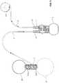
- an artificial sphincter (1)according to the present invention comprises an inflatable occlusion means (20) for occluding a body passage, a stretchable fluid reservoir (23) and a pump means (7) having a first port (13) in fluid communication with the occlusion means (20) and a second port (14) in fluid communication with the fluid reservoir (23) for selectively transferring an isotonic fluid from the occlusion means to the fluid reservoir in order to deflate the occlusion means so that the body passage may be opened.
- an inflatable occlusion means (20)for occluding a body passage
- a stretchable fluid reservoir (23)and a pump means (7) having a first port (13) in fluid communication with the occlusion means (20) and a second port (14) in fluid communication with the fluid reservoir (23) for selectively transferring an isotonic fluid from the occlusion means to the fluid reservoir in order to deflate the occlusion means so that the body passage may be opened.
- the artificial sphincter (1) of the present inventionfurther comprises a pressure compensation balloon (24), which is in fluid communication with said fluid reservoir via a flow passage (28) and which, in use, is to be implanted in the abdomen of a patient.
- a first check valve (30)blocks fluid flow from the second port (14) of the pump means (7) towards said pressure compensation balloon (24).
- a second check valve (26)blocks fluid flow from the fluid reservoir (23) towards the pressure compensation balloon (24).
- the pressure compensation balloon (24)is attached to the fluid reservoir via a connection element (11).
- the connection element (11)has a distribution conduit (12) which has, at its first end, a first check valve (30) blocking fluid flow into said pressure compensation balloon (24) and which has, at its second end, a second check valve (26) blocking fluid flow from said reservoir to said pressure compensation balloon.
- the connection elementhas a flow passage (28) allowing fluid flow from the fluid reservoir to the pressure compensation balloon.
- the distribution conduit (12)is in fluid communication with the second port (14) of the pump means so that the fluid contained in the pressure compensation balloon is freely flowable towards said inflatable occlusion means and, in use, a pressure increase which occurs in the abdomen of a patient is instantly conveyed to said inflatable occlusion means.
- a sudden pressure increase in the abdomen of a patientoccurs usually when the patient coughs, laughs or lifts a heavy object.
- known artificial sphinctersfail to effectively occlude the body passage during said sudden pressure increase.
- urine already accumulated in the bladder of the patientundesirably leaks outside the body of the patient, usually leading the patient feel ashamed in the society.
- the artificial sphincter (1) according to the present inventionoffers a new solution in which the sudden pressure increase is felt or noticed by a pressure compensation balloon (24) located in the in the abdomen and is instantly transmitted to the inflatable occlusion means (20) so that an undesirable leakage of urine is prevented.
- Fig. 2A and Fig. 2Bshow the cross sectional view of the pump means (7) of the artificial sphincter (1) according to the present invention.
- the pump means (7)has a first port (13) in fluid communication with said occlusion means (20) and a second port (14) in fluid communication with said fluid reservoir (23) for selectively transferring isotonic fluid from said occlusion means to said reservoir to deflate said occlusion means so that the body passage (18) may be opened.
- the body passageis opened, as shown in Fig. 4B , when the patient intends to urinate or defecate.
- the term portis used to indicate a node through which fluid exchange may be made in between the occlusion means and the fluid reservoirs.
- the first check valve (30) or the second check valve (26) located in distribution conduit (12)may have pervious seat (10) and a ball (5) which allows fluid flow when the fluid forces said ball towards said pervious seat (10) and which blocks fluid flow when the flow direction of the fluid is reversed.
- the pervious seat (10)may have a plurality of pillars and gaps in between said plurality of gaps so that fluid may pass through the gaps. While the pervious seat (10) is at one side of the ball (5), a converging canal shall be formed on the other or opposite side of the ball (5) so that the ball, under effect of the reverse fluid flow, moves towards the converging canal and clogs the canal.
- the three way valve (15) of the pump means (7)may have a similar design having a pervious seat (10) and a ball (5) which allows fluid flow when the fluid forces said ball towards said pervious seat (10) and which blocks fluid flow when the flow direction of the fluid is reversed.
- the occlusion means (20)has an inflatable cushion (17) having a body passage (18).
- the occlusion meansis designated as a cuff which has an inflatable cushion (17) affixed onto the sheath (19) which is non-extendible.
- the inflatable cushion (19)is implanted such that it surrounds the urethra or rectal canal of a patient and when inflated, occludes the body passage.
- the inflatable cushion (17)occludes the body passage (18) formed in the central area of the inflatable cushion.
- the pump means (7)has a bulb (6) which contains isotonic fluid and which transfers said isotonic fluid to said reservoir (23) when compressed.
- the bulb (6)is made of a material which may shrink when compressed by the fingers of the patient. While the bulb (6) may shrink in volume, it reverts back to its initial shape and volume when not compressed. The material of the bulb (7) would not allow the bulb expand beyond its initial volume even under the working pressure of the artificial sphincter (1).
- the pump means (7)may have a three way valve (15) which is located in between the first port (13) and the second port (14) and which blocks fluid flow towards the occlusion means (20) when the bulb (6) is compressed.
- the three way valve (15)may have a ball (5) seated on a pervious seat (10) and biased by a spring (4) against said pervious seat (10).
- a second tube (8)establishes the fluid connection in between the second port (14) of the pump means (7) and the distribution conduit (12) of the connection element (11).
- the fluid connection in between the occlusion means (20) and the first port (13) of the pump means (7)is established by a first tube (9) as illustrated in Fig. 1 .
- Fluid contained in the pressure compensation balloon (24)may freely flow through the connection element (11) and pump means (7) towards the occlusion means (20) as there is no check valve which would block the flow of fluid from said pressure compensation balloon (24) towards the occlusion means (20). In other words, there is a free flow path for the isotonic fluid when flowing in the direction towards the occlusion means (20).
- the material of the pressure compensation balloon (24)is less elastic than the material of the fluid reservoir (23).
- the pressure compensation balloon (24)may be made of a thicker material so that pressure compensation balloon (24) may stretch less than the fluid reservoir (23) stretches. This provides that fluid reservoir (23) has an internal pressure which is larger than the internal pressure of the pressure compensation balloon (24). In this way, it is ensured that the flow of the isotonic fluid in between the pressure compensation balloon (24) and the fluid reservoir (23) is always towards the pressure compensation balloon (24).
- connection element (11)may have a protrusion (31) protruding towards the inner volume of the pressure compensation balloon (24) for preventing the material of the same clogging fluid entry.
- connection element (11)may have, on its other side, another protrusion (31) protruding towards the inner volume of the fluid reservoir for preventing the material of the same clogging fluid entry.
- the working scheme of the artificial sphincter (1)will be described.
- the working schemewill be detailed by referral to Fig. 5 , Fig. 6A and 6B in which arrows indicate the flow direction of the isotonic fluid in the artificial sphincter (1).
- the occlusion means (20)occludes the body passage (18) and the artificial sphincter (1) reaches a steady state.
- the artificial sphincter (1)should entirely be full of the isotonic fluid having no gaps or air bubbles inside the system. In such a case, if there is zero abdominal pressure change, the isotonic fluid shall be steady and it shall not flow in between the various elements of the artificial sphincter (1).
- the idea underlying the present inventionis to provide a free pathway for the isotonic fluid in between the pressure compensation balloon (24) and the occlusion means (20) so that a sudden abdominal pressure change may be simultaneously transmitted to the occlusion means.
- Fig. 5shows the flow stream of the fluid contained in the artificial sphincter during a moment of sudden abdominal pressure increase, which occurs such as when the patient to which an artificial sphincter (is) was implanted coughs or laughs etc.
- the pressure compensation balloon (24)immediately feels the pressure increase in the abdomen and shrinks in volume.
- the fluid contained in the pressure compensation balloon (24)first flows in the distribution conduit (12) and then towards the second port of the pump means (7) via the second tube (8).
- the fluidfreely passes through the pump means (7) and reaches the occlusion means (20) via a first tube connecting the occlusion means (20) to the first port (13) of the pump means (7).
- the sudden increase in the abdominal pressureis immediately transmitted to the inflatable occlusion means (20).
- the internal pressure of the inflatable occlusion means (20)increases with the incoming fluid flow from the pressure compensation balloon (24), it occludes the body passage (18) more effectively as compared to a steady state.
- connection elementhas a distribution conduit (12) which has, at its second end, a second check valve (26) blocking fluid flow from said fluid reservoir (23) to said pressure compensation balloon (24).
- a distribution conduit (12)which has, at its second end, a second check valve (26) blocking fluid flow from said fluid reservoir (23) to said pressure compensation balloon (24).
- the occlusion means (20)When the patient intends to urinate or defecate, the occlusion means (20) shall be deflated in order to open the body passage (18). Assuming that the artificial sphincter is armed and in steady state, the patient needs to compress and release the bulb (6) a plurality of times. In every compression step, as depicted in Fig. 6A , the fluid contained in the bulb (6) would flow towards the fluid reservoir (23). On the other hand, in every expansion step of the bulb (6), as depicted in Fig. 6B , the fluid contained in the occlusion means (20) and in the pressure compensation balloon (24) flows through the bulb (6).
- the patientcompresses the bulb (6) of the pump means (7) as illustrated in Fig. 6A .
- the isotonic fluid contained in the bulb (6)flows through the three way valve (15) towards the second port (14) of the pump means (7).
- the three way valve (15)blocks the flow towards the first port (13) and hence the occlusion means (20).
- the isotonic fluidflow through the second tube (8) and enters in the distribution conduit (12).
- the first check valve (30) located in the distribution conduit (12)block the flow towards the pressure compensation balloon (24)
- the flowenters in the fluid reservoir (23) and then passes gradually to the pressure compensation balloon (24) via the flow passage (28).
- the retarded flow from fluid reservoir (23) to the pressure compensation balloon (24)provides sufficient time for the patient for urination or defecation. This time is usually in the range of a few minutes before the fluid contained in the pressure compensation balloon (24) flows back to the occlusion means (20) and inflates the same for protection of the patient.
- the fluid flow which occurs automatically during said few minutes until said the occlusion means (20) is fully inflatedis as illustrated in Fig. 5 .
- the bulbWhen the patient releases the bulb (6) of the pump means (7), the bulb reverts back to its original shape and volume.
- the fluid contained in the pressure compensation balloon (23)flows through the second tube (8) and enters the pump means (7) via the second port (14).
- the fluidthen passes through the three way valve (15) and splits in two directions, one towards the bulb (6) and one towards the occlusion means (20) via the first port (13) of the pump means (7).
- the fluid contained in the compensation balloon (24)is transferred only towards the occlusion means (20) in a retarded manner. This retardation is provided by the flow retarder (27) located in the flow passage (28) of the connection element (11).
- the flow retarder (27)provides that the occlusion means (20) reaches its full occlusion pressure in the range of 2-3 minutes after which time the patient is safe against incontinence.
- the fluid contained in the occlusion means (20)flows towards the pump means (7) via the first tube (9).
- the fluidthen moves through the three way valve (15) of the pump means (7) and leaves the pump means (7) via the second tube (8).
- the fluidenters the connection element (11) and flows through the distribution conduit (12) towards the fluid reservoir (23).
- the flow retarder (27) located in the flow passage (28)retards the transfer of the fluid from the fluid reservoir (23) to the pressure compensation balloon (24).
- the retarder (27)allows transfer of the received fluid in the range of 2-3 minutes, during which time the patient is allowed to urinate or defecate.
- the fluid reservoir (23) and the pressure compensation balloon (24)shall, in use, be implanted in the abdomen of the patient suffering incontinence.
- the flow passage (28), which connects fluid reservoir (23) and the pressure compensation balloon (24) and which contains the flow retarder (27)shall normally be implanted in the abdomen of the patient in order to minimize the number of cuts in the abdominal area.
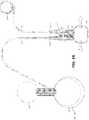
- a connecting element (11)is not used.
- the second tube (8)may split into two branches (8a, 8b) and the first check valve (30) may be located in the first branch (8a) whereas the second check valve (26) may be located in the second branch (8b).
- the first check valve (30)would ensure that the fluid coming from the second port (14) of the pump means would always enter fluid reservoir (23) and not the pressure compensation balloon (24).
- the second check valve (26) located in the second branch (8b)would ensure that the fluid contained in the fluid reservoir (23) would only exit the reservoir through the flow passage (28) towards the pressure compensation balloon (24).
Landscapes
- Health & Medical Sciences (AREA)
- Urology & Nephrology (AREA)
- Cardiology (AREA)
- Oral & Maxillofacial Surgery (AREA)
- Transplantation (AREA)
- Engineering & Computer Science (AREA)
- Biomedical Technology (AREA)
- Heart & Thoracic Surgery (AREA)
- Vascular Medicine (AREA)
- Life Sciences & Earth Sciences (AREA)
- Animal Behavior & Ethology (AREA)
- General Health & Medical Sciences (AREA)
- Public Health (AREA)
- Veterinary Medicine (AREA)
- Prostheses (AREA)
Description
- The present invention generally relates to an apparatus for treating incontinence and more specifically relates an apparatus for providing an inflatable artificial sphincter for control of excretory body passages. The invention provides a novel solution which effectively occludes excretory body passage of a patient even when a sudden pressure increment occurs in the abdomen of a patient to which an artificial sphincter is implanted.
- A biological urinary sphincter prevents urinary flow via mucosal coaptation, compression and pressure transmission. On the other hand, an artificial urinary sphincter mimics the biological urinary sphincter by providing a competent bladder outlet during urinary storage and an open unobstructed outlet to permit voluntary urination. Similarly, an artificial rectal sphincter may be used to treat fecal incontinence caused by neurological or muscular dysfunction of an anal sphincter.
- A known treatment for some cases of incontinence is to provide a patient with a mechanism to occlude the affected excretory body passage. These mechanisms are typically surgically implanted within the patient's body and are adapted to be operable by the patient to selectively open and occlude the body passage. Inflatable artificial sphincters are well known devices in the state of the art. Inflatable sphincters typically include an inflatable cuff for surrounding the passage to be occluded. Usually a pump cooperatively associated with a fluid reservoir is utilized to transfer fluid into and out of the cuff. As fluid is transferred into the cuff, the cuff inflates and closes the circumscribed body passage.
- Artificial urinary sphincters known in the state of the art consist of three major parts, namely the fluid reservoir, the cuff and a pump which is usually designated as the control mechanism of the AUS. The pump can be placed in a man's scrotum. It can also be placed underneath the skin in a woman's lower belly, labia or leg. Two conduit tubes connect all three major parts to each other. Use of an extra element, in particular of a conduit tube, increases the implantation time, complexity of the surgery and most importantly, the infection risk of a patient after implantation within the body.
EP 3,030,196 A1 discloses an entirely implantable device for occluding the urethra or bladder neck utilizing an occlusive cuff connected to a control mechanism via a conduit tube. The occlusive cuff is reversibly changed from an activated occlusive condition to a deactivated non-occlusive condition by depressing a deactivation button contained within a resilient, elastomeric sheath surrounding the control mechanism. Those skilled in the art usually designate this type of occlusion means as AUS, standing for Artificial Urinary Sphincters. Other devices with occlusive cuffs are known fromGB 2174911 US 4222377 .- A known problem with the inflatable artificial sphincters existing in the state of the art is the failure of the cuff in effectively occluding the excretory body passage when a sudden pressure increase occurs in the patient's abdomen. A sudden pressure increase may occur when, for instance, the patient laughs, coughs or is burst into laughter and also by way of certain physical movements such as bending the upper body down or when lifting a weight. In such cases, the normal pressure formed in the inflatable cuff may fail to effectively occlude the excretory body passage and excreted fluid which already accumulated behind the cuff or in the bladder may unintentionally leak outside the patient's body.
- Primary object of the present invention is to provide a new artificial sphincter which eliminates the drawbacks of the existing artificial sphincters.
- In particular, an object of the present invention is to provide a new control mechanism for an artificial sphincter which effectively occludes the excretory body passage of a patient even when a sudden pressure increase occurs in the abdomen of the patient. A further object of the present invention is to provide a new artificial sphincter which is simple and easy to implant in the body of patient suffering incontinence.
- A final object of the present invention is to provide a novel artificial sphincter which is responsive to abdominal pressure changes and which does not require implantation of an extra conduit to the occlusion means. In this context, infection risks and implantation time are reduced and a non-complex artificial sphincter is obtained.
- The figures whose brief explanations are herewith provided are solely intended for providing a better understanding of the present invention and are as such not intended to define the scope of protection or the context in which said scope is interpreted in the absence of the description.
Fig. 1 shows a schematic view of an artificial sphincter according to the present invention,Fig. 2A and Fig. 2B show the cross sectional view of the pump of the artificial sphincter according to the present invention,Fig. 3 shows the cross sectional view of the reservoir and the pressure compensating balloon of the artificial sphincter,Fig. 4A shows 2D view of a cuff in which the urethral passage is in occluded condition,Fig. 4B shows 2D view of a cuff in which the urethral passage is in open condition,Fig. 5 shows the flow stream of the fluid contained in the artificial sphincter during a moment of sudden pressure increase in the abdomen of a patient,Fig. 6A shows the flow stream of the fluid contained in the artificial sphincter during the first step of deflation of the occlusion means,Fig. 6B shows the flow stream of the fluid contained in the artificial sphincter during the second step of deflation of the occlusion meansFig. 7 shows the fluid reservoir and the pressure compensation balloon in the second embodiment of the present invention,Fig. 8 shows the fluid reservoir and the pressure compensation balloon in the third embodiment of the present invention,- The list of reference numerals used in the appended drawings is as follows;
- 1
- artificial sphincter
- 4
- spring
- 5
- ball
- 6
- pump bulb
- 7
- pump
- 8
- second tube
- 8a
- first branch
- 8b
- second branch
- 9
- first tube
- 10
- pervious seat
- 11
- connecting element
- 12
- distribution conduit
- 13
- first port
- 14
- second port
- 15
- three way valve
- 17
- inflatable cushion
- 18
- body passage
- 19
- sheath
- 20
- occlusion means
- 21
- cuff lock
- 23
- Reservoir
- 24
- Pressure compensation balloon
- 26
- second check valve
- 27
- flow retarder
- 28
- flow passage
- 30
- first check valve
- 31
- protrusion
- Objects of the present invention are achieved by the features of
Claim 1 in which an artificial sphincter (1) according to the present invention comprises an inflatable occlusion means (20) for occluding a body passage, a stretchable fluid reservoir (23) and a pump means (7) having a first port (13) in fluid communication with the occlusion means (20) and a second port (14) in fluid communication with the fluid reservoir (23) for selectively transferring an isotonic fluid from the occlusion means to the fluid reservoir in order to deflate the occlusion means so that the body passage may be opened. As illustrated inFig. 1 , the artificial sphincter (1) of the present invention further comprises a pressure compensation balloon (24), which is in fluid communication with said fluid reservoir via a flow passage (28) and which, in use, is to be implanted in the abdomen of a patient. A first check valve (30) blocks fluid flow from the second port (14) of the pump means (7) towards said pressure compensation balloon (24). A second check valve (26) blocks fluid flow from the fluid reservoir (23) towards the pressure compensation balloon (24). Hence, the fluid contained in the pressure compensation balloon is freely flowable towards the inflatable occlusion means and, in use, a pressure increase which occurs in the abdomen of a patient can be instantly conveyed to the inflatable occlusion means. - In the first embodiment, the pressure compensation balloon (24) is attached to the fluid reservoir via a connection element (11). As shown in
Fig. 3 , the connection element (11) has a distribution conduit (12) which has, at its first end, a first check valve (30) blocking fluid flow into said pressure compensation balloon (24) and which has, at its second end, a second check valve (26) blocking fluid flow from said reservoir to said pressure compensation balloon. The connection element has a flow passage (28) allowing fluid flow from the fluid reservoir to the pressure compensation balloon. The distribution conduit (12) is in fluid communication with the second port (14) of the pump means so that the fluid contained in the pressure compensation balloon is freely flowable towards said inflatable occlusion means and, in use, a pressure increase which occurs in the abdomen of a patient is instantly conveyed to said inflatable occlusion means. - A sudden pressure increase in the abdomen of a patient occurs usually when the patient coughs, laughs or lifts a heavy object. As classical artificial sphincters apply a constant pressure in the inflatable occlusion means, known artificial sphincters fail to effectively occlude the body passage during said sudden pressure increase. In such a case, urine already accumulated in the bladder of the patient undesirably leaks outside the body of the patient, usually leading the patient feel ashamed in the society. The artificial sphincter (1) according to the present invention offers a new solution in which the sudden pressure increase is felt or noticed by a pressure compensation balloon (24) located in the in the abdomen and is instantly transmitted to the inflatable occlusion means (20) so that an undesirable leakage of urine is prevented.
- As well known by those skilled in the art, pressure in a liquid medium propagates with the speed of sound under ideal conditions. Hence, any sudden increase in the internal pressure of the abdomen of a patient is immediately transferred to the occlusion means (20) via a pathway through which the isotonic fluid is freely flowable towards the occlusion means. Hence, the pressure of the occlusion means suddenly increases in order to effectively occlude the body passage (18) during the moment of sudden abdominal pressure increase.
Fig. 2A and Fig. 2B show the cross sectional view of the pump means (7) of the artificial sphincter (1) according to the present invention. The pump means (7) has a first port (13) in fluid communication with said occlusion means (20) and a second port (14) in fluid communication with said fluid reservoir (23) for selectively transferring isotonic fluid from said occlusion means to said reservoir to deflate said occlusion means so that the body passage (18) may be opened. The body passage is opened, as shown inFig. 4B , when the patient intends to urinate or defecate. The term port is used to indicate a node through which fluid exchange may be made in between the occlusion means and the fluid reservoirs.- As illustrated in
Fig. 2A andFig. 3 , the first check valve (30) or the second check valve (26) located in distribution conduit (12) may have pervious seat (10) and a ball (5) which allows fluid flow when the fluid forces said ball towards said pervious seat (10) and which blocks fluid flow when the flow direction of the fluid is reversed. The pervious seat (10) may have a plurality of pillars and gaps in between said plurality of gaps so that fluid may pass through the gaps. While the pervious seat (10) is at one side of the ball (5), a converging canal shall be formed on the other or opposite side of the ball (5) so that the ball, under effect of the reverse fluid flow, moves towards the converging canal and clogs the canal. The three way valve (15) of the pump means (7) may have a similar design having a pervious seat (10) and a ball (5) which allows fluid flow when the fluid forces said ball towards said pervious seat (10) and which blocks fluid flow when the flow direction of the fluid is reversed. - As shown in
Fig. 4A and Fig. 4B , the occlusion means (20) has an inflatable cushion (17) having a body passage (18). Usually, the occlusion means is designated as a cuff which has an inflatable cushion (17) affixed onto the sheath (19) which is non-extendible. In use, the inflatable cushion (19) is implanted such that it surrounds the urethra or rectal canal of a patient and when inflated, occludes the body passage. As the sheath (19) surrounding the inflatable cushion (17) does not stretch, the inflatable cushion (17) occludes the body passage (18) formed in the central area of the inflatable cushion. - The pump means (7) has a bulb (6) which contains isotonic fluid and which transfers said isotonic fluid to said reservoir (23) when compressed. The bulb (6) is made of a material which may shrink when compressed by the fingers of the patient. While the bulb (6) may shrink in volume, it reverts back to its initial shape and volume when not compressed. The material of the bulb (7) would not allow the bulb expand beyond its initial volume even under the working pressure of the artificial sphincter (1).
- As illustrated in
Fig. 2A and Fig. 2B , the pump means (7) may have a three way valve (15) which is located in between the first port (13) and the second port (14) and which blocks fluid flow towards the occlusion means (20) when the bulb (6) is compressed. The three way valve (15) may have a ball (5) seated on a pervious seat (10) and biased by a spring (4) against said pervious seat (10). - A second tube (8) establishes the fluid connection in between the second port (14) of the pump means (7) and the distribution conduit (12) of the connection element (11). The fluid connection in between the occlusion means (20) and the first port (13) of the pump means (7) is established by a first tube (9) as illustrated in
Fig. 1 . Fluid contained in the pressure compensation balloon (24) may freely flow through the connection element (11) and pump means (7) towards the occlusion means (20) as there is no check valve which would block the flow of fluid from said pressure compensation balloon (24) towards the occlusion means (20). In other words, there is a free flow path for the isotonic fluid when flowing in the direction towards the occlusion means (20). - In an embodiment, the material of the pressure compensation balloon (24) is less elastic than the material of the fluid reservoir (23). In other words, the pressure compensation balloon (24) may be made of a thicker material so that pressure compensation balloon (24) may stretch less than the fluid reservoir (23) stretches. This provides that fluid reservoir (23) has an internal pressure which is larger than the internal pressure of the pressure compensation balloon (24). In this way, it is ensured that the flow of the isotonic fluid in between the pressure compensation balloon (24) and the fluid reservoir (23) is always towards the pressure compensation balloon (24).
- The connection element (11) may have a protrusion (31) protruding towards the inner volume of the pressure compensation balloon (24) for preventing the material of the same clogging fluid entry. Likewise, the connection element (11) may have, on its other side, another protrusion (31) protruding towards the inner volume of the fluid reservoir for preventing the material of the same clogging fluid entry.
- In the following paragraphs, the working scheme of the artificial sphincter (1) according to the preset invention will be described. The working scheme will be detailed by referral to
Fig. 5 ,Fig. 6A and6B in which arrows indicate the flow direction of the isotonic fluid in the artificial sphincter (1). When the user activates the artificial sphincter (1) the occlusion means (20) occludes the body passage (18) and the artificial sphincter (1) reaches a steady state. During the steady state, the artificial sphincter (1) should entirely be full of the isotonic fluid having no gaps or air bubbles inside the system. In such a case, if there is zero abdominal pressure change, the isotonic fluid shall be steady and it shall not flow in between the various elements of the artificial sphincter (1). - As mentioned earlier, the idea underlying the present invention is to provide a free pathway for the isotonic fluid in between the pressure compensation balloon (24) and the occlusion means (20) so that a sudden abdominal pressure change may be simultaneously transmitted to the occlusion means.
Fig. 5 shows the flow stream of the fluid contained in the artificial sphincter during a moment of sudden abdominal pressure increase, which occurs such as when the patient to which an artificial sphincter (is) was implanted coughs or laughs etc. At such a moment, the pressure compensation balloon (24) immediately feels the pressure increase in the abdomen and shrinks in volume. The fluid contained in the pressure compensation balloon (24) first flows in the distribution conduit (12) and then towards the second port of the pump means (7) via the second tube (8). The fluid freely passes through the pump means (7) and reaches the occlusion means (20) via a first tube connecting the occlusion means (20) to the first port (13) of the pump means (7). Hence, the sudden increase in the abdominal pressure is immediately transmitted to the inflatable occlusion means (20). As the internal pressure of the inflatable occlusion means (20) increases with the incoming fluid flow from the pressure compensation balloon (24), it occludes the body passage (18) more effectively as compared to a steady state.- The connection element has a distribution conduit (12) which has, at its second end, a second check valve (26) blocking fluid flow from said fluid reservoir (23) to said pressure compensation balloon (24). During the moment of an abdominal pressure increase, the fluid leaving the pressure compensation balloon (24) would directly choose the direction to the second port (14) of the pump means via the second tube (8) and would not be directed to the fluid reservoir (23) because the fluid reservoir (23) is subject to the same abdominal pressure increase. The fluid reservoir (23) is subject to shrinking during an abdominal pressure increase and this increase results in transfer of isotonic fluid from the fluid reservoir (23) towards the pressure compensation balloon (24) via flow passage (28) of the connection element (11). As the fluid flow in the flow passage (28) is retarded by a flow retarder (27) located in the flow passage (28), the fluid contained in the fluid reservoir (23) gradually flows towards the pressure compensation balloon (24). Due to the fact that the second check valve (26) blocks fluid flow from said fluid reservoir to said pressure compensation balloon, the only flow path for the fluid contained in the fluid reservoir (23) is the unidirectional flow towards said pressure compensation balloon (24) through the flow passage (28).
- Once the reason for the abdominal pressure increase ceases, i.e. the patient stops laughing or coughing, the extra amount of isotonic liquid transferred to the occlusion means (20) flow back to the fluid reservoir (23). The extra amount of fluid would not flow into the bulb (6) when passing through the pump means (7) due to the fact that the bulb (6) is already full of the isotonic fluid and its material is unable to bulge beyond its original volume.
- When the patient intends to urinate or defecate, the occlusion means (20) shall be deflated in order to open the body passage (18). Assuming that the artificial sphincter is armed and in steady state, the patient needs to compress and release the bulb (6) a plurality of times. In every compression step, as depicted in
Fig. 6A , the fluid contained in the bulb (6) would flow towards the fluid reservoir (23). On the other hand, in every expansion step of the bulb (6), as depicted inFig. 6B , the fluid contained in the occlusion means (20) and in the pressure compensation balloon (24) flows through the bulb (6). Once the bulb (6) is repeatedly compressed and released, all the fluid contained in the occlusion means (20) would be transferred to the fluid reservoir (23) and the occlusion means (20) can be fully deflated. In the fully deflated state, the fluid contained in the occlusion means (20) is fully transferred to the fluid reservoir (23) since the bulb (6) cannot expand in size and continues to contain the same amount of fluid before the deflation cycle was started. Once the occlusion means (20) is fully deflated, the fluid contained in the same is transferred to the fluid reservoir which has an expanded size (23') as shown by broken lines inFig. 6B . - For deflation of the occlusion means (20), the patient compresses the bulb (6) of the pump means (7) as illustrated in
Fig. 6A . Once compressed, the isotonic fluid contained in the bulb (6) flows through the three way valve (15) towards the second port (14) of the pump means (7). During compression of the bulb, the three way valve (15) blocks the flow towards the first port (13) and hence the occlusion means (20). The isotonic fluid flow through the second tube (8) and enters in the distribution conduit (12). As the first check valve (30) located in the distribution conduit (12) block the flow towards the pressure compensation balloon (24), the flow enters in the fluid reservoir (23) and then passes gradually to the pressure compensation balloon (24) via the flow passage (28). The retarded flow from fluid reservoir (23) to the pressure compensation balloon (24) provides sufficient time for the patient for urination or defecation. This time is usually in the range of a few minutes before the fluid contained in the pressure compensation balloon (24) flows back to the occlusion means (20) and inflates the same for protection of the patient. The fluid flow which occurs automatically during said few minutes until said the occlusion means (20) is fully inflated is as illustrated inFig. 5 . - When the patient releases the bulb (6) of the pump means (7), the bulb reverts back to its original shape and volume. The fluid contained in the pressure compensation balloon (23) flows through the second tube (8) and enters the pump means (7) via the second port (14). The fluid then passes through the three way valve (15) and splits in two directions, one towards the bulb (6) and one towards the occlusion means (20) via the first port (13) of the pump means (7). Once the bulb (6) reverts it original size and shape, the fluid contained in the compensation balloon (24) is transferred only towards the occlusion means (20) in a retarded manner. This retardation is provided by the flow retarder (27) located in the flow passage (28) of the connection element (11). When ideally dimensioned, the flow retarder (27) provides that the occlusion means (20) reaches its full occlusion pressure in the range of 2-3 minutes after which time the patient is safe against incontinence.
- During deflation of the artificial sphincter, the fluid contained in the occlusion means (20) flows towards the pump means (7) via the first tube (9). The fluid then moves through the three way valve (15) of the pump means (7) and leaves the pump means (7) via the second tube (8). The fluid enters the connection element (11) and flows through the distribution conduit (12) towards the fluid reservoir (23). Once the occlusion means (20) is fully deflated, the patient would have typically 2-3 minutes for urination or defecation. This is because the fluid transferred to the fluid reservoir (23) will automatically start passing to the pressure compensation balloon (24) through the flow passage (28) of the connection element (11). The flow retarder (27) located in the flow passage (28) retards the transfer of the fluid from the fluid reservoir (23) to the pressure compensation balloon (24). When ideally dimensioned the retarder (27) allows transfer of the received fluid in the range of 2-3 minutes, during which time the patient is allowed to urinate or defecate. Once the received amount of fluid is transferred to the pressure compensation balloon (24), the same fluid will start flowing through the first tube (8), the pump means (7) and the second tube (9) until it reaches the occlusion means (20) and the body passage (28) is automatically occluded.
- The fluid reservoir (23) and the pressure compensation balloon (24) shall, in use, be implanted in the abdomen of the patient suffering incontinence. In such a case, the flow passage (28), which connects fluid reservoir (23) and the pressure compensation balloon (24) and which contains the flow retarder (27) shall normally be implanted in the abdomen of the patient in order to minimize the number of cuts in the abdominal area.
- In the second and third embodiments of the invention, a connecting element (11) is not used. As shown in
Fig. 7 and Fig. 8 , the second tube (8) may split into two branches (8a, 8b) and the first check valve (30) may be located in the first branch (8a) whereas the second check valve (26) may be located in the second branch (8b). In this way, the first check valve (30) would ensure that the fluid coming from the second port (14) of the pump means would always enter fluid reservoir (23) and not the pressure compensation balloon (24). Likewise, the second check valve (26) located in the second branch (8b) would ensure that the fluid contained in the fluid reservoir (23) would only exit the reservoir through the flow passage (28) towards the pressure compensation balloon (24). As in the case of the first embodiment, during the inflation cycle of the occlusion means, fluid coming from the pressure compensation balloon (24) would be prevented from entering the fluid reservoir (23) and would always follow its free path towards occlusion means (20) via the pump means (7). This latter ensures that any pressure increase which may occur in the abdomen of the patient would immediately be felt by the occlusion means so that the body passage would be occluded with an increased working pressure of the occlusion means.
Claims (12)
- An artificial sphincter (1) containing, in use, an isotonic fluid, said artificial sphincter (1) comprising:an inflatable occlusion means (20) for occluding a body passage,a stretchable fluid reservoir (23),a pump means (7) having a first port (13) in fluid communication with said occlusion means (20) via a first tube (9) and a second port (14) in fluid communication with said fluid reservoir (23) via a second tube (8) for selectively transferring isotonic fluid from said occlusion means to said reservoir to deflate said occlusion means so that the body passage may be opened;characterized in that the artificial sphincter (1) further comprises;a pressure compensation balloon (24), which is in fluid communication with said fluid reservoir via a flow passage (28) and which, in use, is to be implanted in the abdomen of a patient,a first check valve (30) blocking fluid flow from the second port (14) of the pump means (7) towards said pressure compensation balloon (24),a second check valve (26) blocking fluid flow from the fluid reservoir (23) towards said pressure compensation balloon (24),whereby the fluid contained in the pressure compensation balloon is freely flowable towards said inflatable occlusion means and, in use, a pressure increase which occurs in the abdomen of a patient is instantly conveyed to said inflatable occlusion means.
- An artificial sphincter (1) as set forth in Claim 1 wherein the flow passage (28) connecting the fluid reservoir (23) and the pressure compensation balloon (24), comprises a flow retarder (27) retarding the flow of fluid from reservoir (23) to the pressure compensation balloon (24).
- An artificial sphincter (1) as set forth in Claim 1 wherein said pump means (7) has a bulb (6) which contains isotonic fluid and which transfers said isotonic fluid to said reservoir (23) when compressed.
- An artificial sphincter (1) as set forth in Claim 3 wherein said pump means (7) has a three way valve (15) which is located in between the first port (13) and the second port (14) and which blocks fluid flow towards the occlusion means (20) when the bulb (6) is compressed.
- An artificial sphincter (1) as set forth in Claim 3 wherein said pump means (7) has a three way valve (15) which allows fluid flow from said first and second ports (13,14) towards the bulb (6) of said pump means (7).
- An artificial sphincter (1) as set forth in Claim 1 wherein said occlusion means (20) has an inflatable cushion (17) having a body passage (18).
- An artificial sphincter (1) as set forth in Claim 1 wherein the material of the pressure compensation balloon (24) is less elastic than the material of the fluid reservoir (23) so that the fluid reservoir (23) stretches more than the pressure compensation balloon (24) stretches.
- An artificial sphincter (1) as set forth in Claim 1 wherein each of said first check valve (30) and second check valve (26) has a pervious seat (10) and a ball (5) which allows fluid flow when the fluid forces said ball towards said pervious seat (10) and which blocks fluid flow when the flow direction of the fluid is reversed.
- An artificial sphincter (1) as set forth in Claim 4 wherein said three way valve (15) has a ball (5) seated on a pervious seat (10) and biased by a spring (4) against said pervious seat (10).
- An artificial sphincter (1) as set forth in Claim 1 wherein said first check valve (30) and second check valve (26) is formed in a connecting element (11).
- An artificial sphincter (1) as set forth in Claim 10 wherein said connection element (11) has a protrusion (31) protruding towards the inner volume of the pressure compensation balloon (24) for preventing the material of the same clogging fluid entry.
- An artificial sphincter (1) as set forth in Claim 1 wherein the occlusion means (20) is sized and shaped to occlude an anal or urethral canal of a human being.
Applications Claiming Priority (1)
| Application Number | Priority Date | Filing Date | Title |
|---|---|---|---|
| PCT/TR2017/050076WO2018156092A1 (en) | 2017-02-27 | 2017-02-27 | Improved artificial sphinchter |
Publications (2)
| Publication Number | Publication Date |
|---|---|
| EP3585303A1 EP3585303A1 (en) | 2020-01-01 |
| EP3585303B1true EP3585303B1 (en) | 2020-07-01 |
Family
ID=58461417
Family Applications (1)
| Application Number | Title | Priority Date | Filing Date |
|---|---|---|---|
| EP17714923.4AActiveEP3585303B1 (en) | 2017-02-27 | 2017-02-27 | Improved artificial sphinchter |
Country Status (4)
| Country | Link |
|---|---|
| US (1) | US11103337B2 (en) |
| EP (1) | EP3585303B1 (en) |
| ES (1) | ES2822005T3 (en) |
| WO (1) | WO2018156092A1 (en) |
Families Citing this family (9)
| Publication number | Priority date | Publication date | Assignee | Title |
|---|---|---|---|---|
| WO2009135141A1 (en) | 2008-05-01 | 2009-11-05 | Bristol-Myers Squibb Company | Rectal drain appliance |
| CN108578044A (en) | 2011-03-17 | 2018-09-28 | 康沃特克科技公司 | High barrier elastomer excrement conduit or ostomy bag |
| PL3027266T3 (en) | 2013-08-01 | 2023-09-04 | Convatec Technologies Inc. | Self-closing bag connector |
| GB201721956D0 (en) | 2017-12-27 | 2018-02-07 | Convatec Ltd | Female catheter locator tip |
| GB201721955D0 (en) | 2017-12-27 | 2018-02-07 | Convatec Ltd | Catheter wetting devices |
| US20210290427A1 (en)* | 2019-03-04 | 2021-09-23 | Kaohsiung Chang Gung Memorial Hospital | Artificial stoma device |
| CA3140906A1 (en) | 2019-06-11 | 2020-12-17 | Convatec Technologies Inc. | Urine collection bags for use with catheter products, kits incorporating the same, and methods therefor |
| CN112494786B (en)* | 2021-02-05 | 2021-05-07 | 北京泰杰伟业科技有限公司 | Balloon catheter device |
| WO2023282860A1 (en) | 2021-07-08 | 2023-01-12 | Lueleci Hueseyin | Improved reflex artificial sphinchter |
Family Cites Families (6)
| Publication number | Priority date | Publication date | Assignee | Title |
|---|---|---|---|---|
| US4222377A (en)* | 1977-06-27 | 1980-09-16 | American Medical Systems, Inc. | Pressure regulated artificial sphincter systems |
| US4386601A (en)* | 1981-08-12 | 1983-06-07 | Medical Engineering Corporation | Artificial sphincter |
| GB8512069D0 (en)* | 1985-05-13 | 1985-06-19 | Craggs M D | Prosthetic sphincter devices |
| US4994020A (en) | 1989-07-21 | 1991-02-19 | American Medical Systems, Inc. | Implantable artificial sphincter system |
| GB9202247D0 (en)* | 1992-02-03 | 1992-03-18 | British Tech Group | Prosthetic sphincter device |
| EP3030196A4 (en) | 2013-08-06 | 2016-12-28 | Gt Urological Llc | Hydraulic urethral occlusive device |
- 2017
- 2017-02-27EPEP17714923.4Apatent/EP3585303B1/enactiveActive
- 2017-02-27WOPCT/TR2017/050076patent/WO2018156092A1/ennot_activeCeased
- 2017-02-27USUS16/481,839patent/US11103337B2/enactiveActive
- 2017-02-27ESES17714923Tpatent/ES2822005T3/enactiveActive
Non-Patent Citations (1)
| Title |
|---|
| None* |
Also Published As
| Publication number | Publication date |
|---|---|
| WO2018156092A1 (en) | 2018-08-30 |
| US11103337B2 (en) | 2021-08-31 |
| ES2822005T3 (en) | 2021-04-28 |
| EP3585303A1 (en) | 2020-01-01 |
| US20190374324A1 (en) | 2019-12-12 |
Similar Documents
| Publication | Publication Date | Title |
|---|---|---|
| EP3585303B1 (en) | Improved artificial sphinchter | |
| US5593443A (en) | Prosthetic anal sphincter | |
| US4800900A (en) | External strap incontinence control device | |
| US4222377A (en) | Pressure regulated artificial sphincter systems | |
| US5112306A (en) | Method and apparatus for valving body fluids | |
| US5562598A (en) | Artificial urethral sphincter | |
| CA1253651A (en) | Single circuit fluidic sphincter | |
| US4419985A (en) | Apparatus for reversibly closing a body passage | |
| US7608067B2 (en) | Patient-adjustable incontinence device (AID) | |
| EP0444831B1 (en) | Female incontinence control device with mechanically operable valve | |
| US6491623B2 (en) | Device for preventing fecal incontinence | |
| US20030153807A1 (en) | Urinary flow control device & method | |
| GB2355937A (en) | Urinary sphincter device | |
| JPH0357448A (en) | Implantable sphincter device | |
| US9301824B2 (en) | Hydraulic urethral occlusive device | |
| HK1224166A1 (en) | Hydraulic urethral occlusive device | |
| US20100256757A1 (en) | Artificial sphincter | |
| EP4366658B1 (en) | An improved pump for an artificial sphinchter | |
| WO2013165564A1 (en) | Passive artificial sphincter |
Legal Events
| Date | Code | Title | Description |
|---|---|---|---|
| STAA | Information on the status of an ep patent application or granted ep patent | Free format text:STATUS: UNKNOWN | |
| STAA | Information on the status of an ep patent application or granted ep patent | Free format text:STATUS: THE INTERNATIONAL PUBLICATION HAS BEEN MADE | |
| PUAI | Public reference made under article 153(3) epc to a published international application that has entered the european phase | Free format text:ORIGINAL CODE: 0009012 | |
| STAA | Information on the status of an ep patent application or granted ep patent | Free format text:STATUS: REQUEST FOR EXAMINATION WAS MADE | |
| 17P | Request for examination filed | Effective date:20190822 | |
| AK | Designated contracting states | Kind code of ref document:A1 Designated state(s):AL AT BE BG CH CY CZ DE DK EE ES FI FR GB GR HR HU IE IS IT LI LT LU LV MC MK MT NL NO PL PT RO RS SE SI SK SM TR | |
| AX | Request for extension of the european patent | Extension state:BA ME | |
| GRAP | Despatch of communication of intention to grant a patent | Free format text:ORIGINAL CODE: EPIDOSNIGR1 | |
| STAA | Information on the status of an ep patent application or granted ep patent | Free format text:STATUS: GRANT OF PATENT IS INTENDED | |
| DAV | Request for validation of the european patent (deleted) | ||
| DAX | Request for extension of the european patent (deleted) | ||
| INTG | Intention to grant announced | Effective date:20200120 | |
| GRAS | Grant fee paid | Free format text:ORIGINAL CODE: EPIDOSNIGR3 | |
| GRAA | (expected) grant | Free format text:ORIGINAL CODE: 0009210 | |
| STAA | Information on the status of an ep patent application or granted ep patent | Free format text:STATUS: THE PATENT HAS BEEN GRANTED | |
| AK | Designated contracting states | Kind code of ref document:B1 Designated state(s):AL AT BE BG CH CY CZ DE DK EE ES FI FR GB GR HR HU IE IS IT LI LT LU LV MC MK MT NL NO PL PT RO RS SE SI SK SM TR | |
| REG | Reference to a national code | Ref country code:AT Ref legal event code:REF Ref document number:1285431 Country of ref document:AT Kind code of ref document:T Effective date:20200715 Ref country code:CH Ref legal event code:EP | |
| REG | Reference to a national code | Ref country code:IE Ref legal event code:FG4D | |
| REG | Reference to a national code | Ref country code:DE Ref legal event code:R096 Ref document number:602017019006 Country of ref document:DE | |
| REG | Reference to a national code | Ref country code:LT Ref legal event code:MG4D | |
| PG25 | Lapsed in a contracting state [announced via postgrant information from national office to epo] | Ref country code:BG Free format text:LAPSE BECAUSE OF FAILURE TO SUBMIT A TRANSLATION OF THE DESCRIPTION OR TO PAY THE FEE WITHIN THE PRESCRIBED TIME-LIMIT Effective date:20201001 | |
| REG | Reference to a national code | Ref country code:NL Ref legal event code:MP Effective date:20200701 | |
| REG | Reference to a national code | Ref country code:AT Ref legal event code:MK05 Ref document number:1285431 Country of ref document:AT Kind code of ref document:T Effective date:20200701 | |
| PG25 | Lapsed in a contracting state [announced via postgrant information from national office to epo] | Ref country code:FI Free format text:LAPSE BECAUSE OF FAILURE TO SUBMIT A TRANSLATION OF THE DESCRIPTION OR TO PAY THE FEE WITHIN THE PRESCRIBED TIME-LIMIT Effective date:20200701 Ref country code:CZ Free format text:LAPSE BECAUSE OF FAILURE TO SUBMIT A TRANSLATION OF THE DESCRIPTION OR TO PAY THE FEE WITHIN THE PRESCRIBED TIME-LIMIT Effective date:20200701 Ref country code:NO Free format text:LAPSE BECAUSE OF FAILURE TO SUBMIT A TRANSLATION OF THE DESCRIPTION OR TO PAY THE FEE WITHIN THE PRESCRIBED TIME-LIMIT Effective date:20201001 Ref country code:LT Free format text:LAPSE BECAUSE OF FAILURE TO SUBMIT A TRANSLATION OF THE DESCRIPTION OR TO PAY THE FEE WITHIN THE PRESCRIBED TIME-LIMIT Effective date:20200701 Ref country code:GR Free format text:LAPSE BECAUSE OF FAILURE TO SUBMIT A TRANSLATION OF THE DESCRIPTION OR TO PAY THE FEE WITHIN THE PRESCRIBED TIME-LIMIT Effective date:20201002 Ref country code:PT Free format text:LAPSE BECAUSE OF FAILURE TO SUBMIT A TRANSLATION OF THE DESCRIPTION OR TO PAY THE FEE WITHIN THE PRESCRIBED TIME-LIMIT Effective date:20201102 Ref country code:SE Free format text:LAPSE BECAUSE OF FAILURE TO SUBMIT A TRANSLATION OF THE DESCRIPTION OR TO PAY THE FEE WITHIN THE PRESCRIBED TIME-LIMIT Effective date:20200701 Ref country code:HR Free format text:LAPSE BECAUSE OF FAILURE TO SUBMIT A TRANSLATION OF THE DESCRIPTION OR TO PAY THE FEE WITHIN THE PRESCRIBED TIME-LIMIT Effective date:20200701 Ref country code:AT Free format text:LAPSE BECAUSE OF FAILURE TO SUBMIT A TRANSLATION OF THE DESCRIPTION OR TO PAY THE FEE WITHIN THE PRESCRIBED TIME-LIMIT Effective date:20200701 | |
| PG25 | Lapsed in a contracting state [announced via postgrant information from national office to epo] | Ref country code:IS Free format text:LAPSE BECAUSE OF FAILURE TO SUBMIT A TRANSLATION OF THE DESCRIPTION OR TO PAY THE FEE WITHIN THE PRESCRIBED TIME-LIMIT Effective date:20201101 Ref country code:PL Free format text:LAPSE BECAUSE OF FAILURE TO SUBMIT A TRANSLATION OF THE DESCRIPTION OR TO PAY THE FEE WITHIN THE PRESCRIBED TIME-LIMIT Effective date:20200701 Ref country code:RS Free format text:LAPSE BECAUSE OF FAILURE TO SUBMIT A TRANSLATION OF THE DESCRIPTION OR TO PAY THE FEE WITHIN THE PRESCRIBED TIME-LIMIT Effective date:20200701 Ref country code:LV Free format text:LAPSE BECAUSE OF FAILURE TO SUBMIT A TRANSLATION OF THE DESCRIPTION OR TO PAY THE FEE WITHIN THE PRESCRIBED TIME-LIMIT Effective date:20200701 | |
| PG25 | Lapsed in a contracting state [announced via postgrant information from national office to epo] | Ref country code:NL Free format text:LAPSE BECAUSE OF FAILURE TO SUBMIT A TRANSLATION OF THE DESCRIPTION OR TO PAY THE FEE WITHIN THE PRESCRIBED TIME-LIMIT Effective date:20200701 | |
| REG | Reference to a national code | Ref country code:DE Ref legal event code:R097 Ref document number:602017019006 Country of ref document:DE | |
| REG | Reference to a national code | Ref country code:ES Ref legal event code:FG2A Ref document number:2822005 Country of ref document:ES Kind code of ref document:T3 Effective date:20210428 | |
| PG25 | Lapsed in a contracting state [announced via postgrant information from national office to epo] | Ref country code:DK Free format text:LAPSE BECAUSE OF FAILURE TO SUBMIT A TRANSLATION OF THE DESCRIPTION OR TO PAY THE FEE WITHIN THE PRESCRIBED TIME-LIMIT Effective date:20200701 Ref country code:RO Free format text:LAPSE BECAUSE OF FAILURE TO SUBMIT A TRANSLATION OF THE DESCRIPTION OR TO PAY THE FEE WITHIN THE PRESCRIBED TIME-LIMIT Effective date:20200701 Ref country code:SM Free format text:LAPSE BECAUSE OF FAILURE TO SUBMIT A TRANSLATION OF THE DESCRIPTION OR TO PAY THE FEE WITHIN THE PRESCRIBED TIME-LIMIT Effective date:20200701 Ref country code:EE Free format text:LAPSE BECAUSE OF FAILURE TO SUBMIT A TRANSLATION OF THE DESCRIPTION OR TO PAY THE FEE WITHIN THE PRESCRIBED TIME-LIMIT Effective date:20200701 | |
| PLBE | No opposition filed within time limit | Free format text:ORIGINAL CODE: 0009261 | |
| STAA | Information on the status of an ep patent application or granted ep patent | Free format text:STATUS: NO OPPOSITION FILED WITHIN TIME LIMIT | |
| PG25 | Lapsed in a contracting state [announced via postgrant information from national office to epo] | Ref country code:AL Free format text:LAPSE BECAUSE OF FAILURE TO SUBMIT A TRANSLATION OF THE DESCRIPTION OR TO PAY THE FEE WITHIN THE PRESCRIBED TIME-LIMIT Effective date:20200701 | |
| 26N | No opposition filed | Effective date:20210406 | |
| PG25 | Lapsed in a contracting state [announced via postgrant information from national office to epo] | Ref country code:SK Free format text:LAPSE BECAUSE OF FAILURE TO SUBMIT A TRANSLATION OF THE DESCRIPTION OR TO PAY THE FEE WITHIN THE PRESCRIBED TIME-LIMIT Effective date:20200701 | |
| PG25 | Lapsed in a contracting state [announced via postgrant information from national office to epo] | Ref country code:MC Free format text:LAPSE BECAUSE OF FAILURE TO SUBMIT A TRANSLATION OF THE DESCRIPTION OR TO PAY THE FEE WITHIN THE PRESCRIBED TIME-LIMIT Effective date:20200701 | |
| REG | Reference to a national code | Ref country code:BE Ref legal event code:MM Effective date:20210228 | |
| PG25 | Lapsed in a contracting state [announced via postgrant information from national office to epo] | Ref country code:LI Free format text:LAPSE BECAUSE OF NON-PAYMENT OF DUE FEES Effective date:20210228 Ref country code:LU Free format text:LAPSE BECAUSE OF NON-PAYMENT OF DUE FEES Effective date:20210227 Ref country code:CH Free format text:LAPSE BECAUSE OF NON-PAYMENT OF DUE FEES Effective date:20210228 | |
| PG25 | Lapsed in a contracting state [announced via postgrant information from national office to epo] | Ref country code:IE Free format text:LAPSE BECAUSE OF NON-PAYMENT OF DUE FEES Effective date:20210227 | |
| PG25 | Lapsed in a contracting state [announced via postgrant information from national office to epo] | Ref country code:BE Free format text:LAPSE BECAUSE OF NON-PAYMENT OF DUE FEES Effective date:20210228 | |
| PG25 | Lapsed in a contracting state [announced via postgrant information from national office to epo] | Ref country code:CY Free format text:LAPSE BECAUSE OF FAILURE TO SUBMIT A TRANSLATION OF THE DESCRIPTION OR TO PAY THE FEE WITHIN THE PRESCRIBED TIME-LIMIT Effective date:20200701 | |
| P01 | Opt-out of the competence of the unified patent court (upc) registered | Effective date:20230606 | |
| PG25 | Lapsed in a contracting state [announced via postgrant information from national office to epo] | Ref country code:HU Free format text:LAPSE BECAUSE OF FAILURE TO SUBMIT A TRANSLATION OF THE DESCRIPTION OR TO PAY THE FEE WITHIN THE PRESCRIBED TIME-LIMIT; INVALID AB INITIO Effective date:20170227 | |
| PG25 | Lapsed in a contracting state [announced via postgrant information from national office to epo] | Ref country code:SI Free format text:LAPSE BECAUSE OF FAILURE TO SUBMIT A TRANSLATION OF THE DESCRIPTION OR TO PAY THE FEE WITHIN THE PRESCRIBED TIME-LIMIT Effective date:20200701 | |
| PG25 | Lapsed in a contracting state [announced via postgrant information from national office to epo] | Ref country code:MK Free format text:LAPSE BECAUSE OF FAILURE TO SUBMIT A TRANSLATION OF THE DESCRIPTION OR TO PAY THE FEE WITHIN THE PRESCRIBED TIME-LIMIT Effective date:20200701 | |
| PG25 | Lapsed in a contracting state [announced via postgrant information from national office to epo] | Ref country code:MT Free format text:LAPSE BECAUSE OF FAILURE TO SUBMIT A TRANSLATION OF THE DESCRIPTION OR TO PAY THE FEE WITHIN THE PRESCRIBED TIME-LIMIT Effective date:20200701 | |
| PGFP | Annual fee paid to national office [announced via postgrant information from national office to epo] | Ref country code:DE Payment date:20250212 Year of fee payment:9 | |
| PGFP | Annual fee paid to national office [announced via postgrant information from national office to epo] | Ref country code:ES Payment date:20250317 Year of fee payment:9 | |
| PGFP | Annual fee paid to national office [announced via postgrant information from national office to epo] | Ref country code:FR Payment date:20250228 Year of fee payment:9 | |
| PGFP | Annual fee paid to national office [announced via postgrant information from national office to epo] | Ref country code:IT Payment date:20250207 Year of fee payment:9 Ref country code:GB Payment date:20250221 Year of fee payment:9 | |
| PGFP | Annual fee paid to national office [announced via postgrant information from national office to epo] | Ref country code:TR Payment date:20250207 Year of fee payment:9 |