EP3583975A1 - Frontal sinus dilation catheter - Google Patents
Frontal sinus dilation catheterDownload PDFInfo
- Publication number
- EP3583975A1 EP3583975A1EP19189716.4AEP19189716AEP3583975A1EP 3583975 A1EP3583975 A1EP 3583975A1EP 19189716 AEP19189716 AEP 19189716AEP 3583975 A1EP3583975 A1EP 3583975A1
- Authority
- EP
- European Patent Office
- Prior art keywords
- balloon
- guide member
- inner guide
- dilation catheter
- shaft
- Prior art date
- Legal status (The legal status is an assumption and is not a legal conclusion. Google has not performed a legal analysis and makes no representation as to the accuracy of the status listed.)
- Granted
Links
Images


Classifications
- A—HUMAN NECESSITIES
- A61—MEDICAL OR VETERINARY SCIENCE; HYGIENE
- A61M—DEVICES FOR INTRODUCING MEDIA INTO, OR ONTO, THE BODY; DEVICES FOR TRANSDUCING BODY MEDIA OR FOR TAKING MEDIA FROM THE BODY; DEVICES FOR PRODUCING OR ENDING SLEEP OR STUPOR
- A61M29/00—Dilators with or without means for introducing media, e.g. remedies
- A61M29/02—Dilators made of swellable material
- A—HUMAN NECESSITIES
- A61—MEDICAL OR VETERINARY SCIENCE; HYGIENE
- A61B—DIAGNOSIS; SURGERY; IDENTIFICATION
- A61B17/00—Surgical instruments, devices or methods
- A61B17/24—Surgical instruments, devices or methods for use in the oral cavity, larynx, bronchial passages or nose; Tongue scrapers
- A—HUMAN NECESSITIES
- A61—MEDICAL OR VETERINARY SCIENCE; HYGIENE
- A61B—DIAGNOSIS; SURGERY; IDENTIFICATION
- A61B34/00—Computer-aided surgery; Manipulators or robots specially adapted for use in surgery
- A61B34/20—Surgical navigation systems; Devices for tracking or guiding surgical instruments, e.g. for frameless stereotaxis
- A—HUMAN NECESSITIES
- A61—MEDICAL OR VETERINARY SCIENCE; HYGIENE
- A61B—DIAGNOSIS; SURGERY; IDENTIFICATION
- A61B34/00—Computer-aided surgery; Manipulators or robots specially adapted for use in surgery
- A61B34/30—Surgical robots
- A—HUMAN NECESSITIES
- A61—MEDICAL OR VETERINARY SCIENCE; HYGIENE
- A61M—DEVICES FOR INTRODUCING MEDIA INTO, OR ONTO, THE BODY; DEVICES FOR TRANSDUCING BODY MEDIA OR FOR TAKING MEDIA FROM THE BODY; DEVICES FOR PRODUCING OR ENDING SLEEP OR STUPOR
- A61M25/00—Catheters; Hollow probes
- A61M25/01—Introducing, guiding, advancing, emplacing or holding catheters
- A61M25/0105—Steering means as part of the catheter or advancing means; Markers for positioning
- A61M25/0113—Mechanical advancing means, e.g. catheter dispensers
- A—HUMAN NECESSITIES
- A61—MEDICAL OR VETERINARY SCIENCE; HYGIENE
- A61M—DEVICES FOR INTRODUCING MEDIA INTO, OR ONTO, THE BODY; DEVICES FOR TRANSDUCING BODY MEDIA OR FOR TAKING MEDIA FROM THE BODY; DEVICES FOR PRODUCING OR ENDING SLEEP OR STUPOR
- A61M25/00—Catheters; Hollow probes
- A61M25/10—Balloon catheters
- A—HUMAN NECESSITIES
- A61—MEDICAL OR VETERINARY SCIENCE; HYGIENE
- A61B—DIAGNOSIS; SURGERY; IDENTIFICATION
- A61B17/00—Surgical instruments, devices or methods
- A61B17/24—Surgical instruments, devices or methods for use in the oral cavity, larynx, bronchial passages or nose; Tongue scrapers
- A61B2017/246—Surgical instruments, devices or methods for use in the oral cavity, larynx, bronchial passages or nose; Tongue scrapers for cleaning of the nose
Definitions
- the field of the inventiongenerally relates to balloon inflation devices and methods. More particularly, the field of the invention relates to balloon dilation devices and methods for the treatment of sinusitis.
- Sinusitisis a condition affecting over 35 million Americans, and similarly large populations in the rest of the developed world. Sinusitis occurs when one or more of the four paired sinus cavities (i.e., maxillary, ethmoid, frontal, sphenoid) becomes obstructed, or otherwise has compromised drainage. Normally the sinus cavities, each of which are lined by mucosa, produce mucous which is then moved by beating cilia from the sinus cavity out to the nasal cavity and down the throat. The combined sinuses produce approximately one liter of mucous daily, so the effective transport of this mucous is important to sinus health.
- sinus cavitiesi.e., maxillary, ethmoid, frontal, sphenoid
- mucosaNormally the sinus cavities, each of which are lined by mucosa, produce mucous which is then moved by beating cilia from the sinus cavity out to the nasal cavity and down the throat.
- the combined sinusesproduce approximately one liter of mucous daily, so
- Each sinus cavityhas a drainage pathway or outflow tract opening into the nasal passage.
- This drainage passagewaycan include an ostium, as well as a "transition space" in the region of the ostia, such as the "frontal recess,” in the case of the frontal sinus, or an "ethmoidal infundibulum,” in the case of the maxillary sinus.
- sinusitismay be treatable with appropriate medicates, in some cases sinusitis persists for months or more, a condition called chronic sinusitis, and may not respond to medical therapy. Some patients are also prone to multiple episodes of sinusitis in a given period of time, a condition called recurrent sinusitis.
- Balloon dilationhas been applied to treat constricted sinus passageways for the treatment of sinusitis.
- These balloon dilation devicestypically involve the use of an inflatable balloon located at the distal end of a catheter such as a balloon catheter.
- the inflatable balloonis inserted into the constricted sinus passageway in a deflated state.
- the balloonis then expanded to open or reduce the degree of constriction in the sinus passageway being treated to facilitate better sinus drainage and ventilation.
- most, if not all, of the functional mucosal tissue lining of the sinuses and their drainage passagewaysare preserved.
- Exemplary devices and methods particularly suited for the dilation of anatomic structures associated with the maxillary and anterior ethmoid sinusesare disclosed, for example, in U.S. Patent No. 7,520,876 and U.S. Patent Application Publication No. 2008-0172033 .
- Other systemshave been described for the treatment of various other sinuses including the frontal sinus.
- U.S. Patent Application Publication No. 2008-0097295discloses a frontal sinus guide catheter ( FIG. 6B ) and method of treating the frontal sinuses (e.g., FIGS. 8B-8C ).
- U.S. Patent Application Publication No. 2008-0125626discloses another guide device (e.g., FIGS. 10C and 10C ) for transnasal access to the frontal sinuses for treatment.
- a balloon dilation catheterin a first embodiment, includes a substantially rigid inner guide member and a movable shaft coupled to a balloon that is slidably mounted on the substantially rigid inner guide member.
- a sinus cavitye.g., frontal sinus cavity
- the substantially rigid inner guide memberis advanced into a drainage pathway of the subject via a nasal passageway.
- the shaft and balloonare then advanced in a distal direction over the substantially rigid inner guide member to place the balloon in the drainage pathway. This enables the balloon to track over the inner guide member.
- the balloonis inflated to expand or otherwise remodel the drainage pathway. Where the sinus cavity is the frontal sinus cavity the drainage pathway is the frontal recess.
- a device for dilating the outflow tract of a sinus cavityincludes a substantially rigid inner guide member having a proximal end and a distal end and a shaft coupled to a balloon, the shaft having a first lumen along at least a portion thereof containing the substantially rigid inner guide member, the shaft having a second lumen operatively coupled to the interior of the balloon.
- a handleis disposed along a proximal portion of the substantially rigid inner guide member, the handle including a moveable knob operatively coupled to the shaft, wherein distal advancement of the knob advances the shaft and balloon over the substantially rigid inner guide in a distal direction.
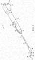
- FIG. 1illustrates one embodiment of a balloon dilation catheter 10 that is particularly suited for treatment of the outflow tract (frontal sinus ostium and frontal recess) of the frontal sinus of a subject.
- the balloon dilation catheter 10includes a handle 12 that is configured to be gripped or otherwise manipulated by the operator.
- An elongate-shaped inner guide member 14extends longitudinally from the handle 12 in a distal direction.
- the inner guide member 14is formed of a suitably rigid material such as stainless steel hypotube.
- the inner guide member 14projects or otherwise extends distally from the handle 12 for a pre-determined distance.
- the inner guide member 14may be pre-shaped to have a curved distal portion 16 as is illustrated in FIGS.
- the nature and degree of the curved distal portion 16may be configured to match with the frontal sinus outflow tract or frontal recess.
- the inner guide member 14may have some degree of malleability such that the user may bend or impart some desired shape or configuration to the distal end of the inner guide member 14.
- the inner guide member 14may include an optional lumen 18 (best illustrated in FIG. 5A ) that extends the length of the inner guide member 14.
- the inner guide member 14 and the contained lumen 18may extend from a distal end 20 to a proximal end 21 (best seen in FIGS. 2B and 3B ) that interfaces with a sealed arrangement with a port 22 disposed at a proximal end 24 of the handle 12.
- the port 22may be configured with a conventional interface such as a Luer connector.
- the port 22may be used as an aspiration port or a delivery port for fluids and/or medicaments, or for introduction of a guide wire.
- a shaft 30is mounted about the periphery of the inner guide member 14.
- the shaft 30is dimensioned to slide over the inner guide member 14 in response to actuation of an advancer knob 32 located on the handle 12.
- the advancer knob 32is moveable along a slot 42 contained in a surface of the handle 12.
- a distal end 34 of the shaft 30includes a balloon 36 that is configured to be selectively inflated or deflated as explained herein.
- the inner guide member 14is manipulated and advanced across or into the anatomical space of interest.
- FIG. 1illustrates the balloon 36 in an inflated state for better illustration, the balloon 36 is typically in a deflated state when the shaft 30 is in the proximal position as illustrated in FIGS. 2A and 2B .
- the useractuates the advancer knob 32 by sliding the same in the distal direction which, in turn, advances the shaft 30 and balloon 36 in a distal direction over the pre-placed inner guide member 14.
- the balloon 36is inflated. Inflation of the balloon 36 is accomplished using an inflation device (not shown) that is coupled to a port 38 located at the proximal end 24 of the handle 12.
- An inflation lumen 48 contained within the shaft 30(described in more detail below), fluidically couples the port 38 to an interior portion of the balloon 36.
- an optional support member 40 in the form of a tubemay be located about the external periphery of a portion of the shaft 30 to impart further stiffness to the balloon dilation catheter 10.
- the particular length of the support member 40may vary depending on the application and may extend along some or all or the shaft 30.
- the support member 40may be made of a metallic material such as stainless steel hypotube that is secured to the shaft 30.
- the support member 40may be welded or bonded along a length of the shaft 30. Generally, the support member 40 does not cover the helical portion (described in detail below) of the shaft 30 that is contained within the handle 12.
- FIGS. 2A and 2Billustrate, respectively, side and cross-sectional views of the balloon dilation catheter 10 with the advancer knob 32 and thus balloon 36 in the proximal position.
- the balloon 36is typically in a deflated state when the advancer knob 32 is the proximal position as illustrated in FIGS. 2A and 2B .
- the advancer knob 32is slidably disposed along a length of the handle 12 inside a slot 42.
- the advancer knob 32is thus able to slide back and forth in the distal/proximal direction along the length of the slot 42.
- the slot 42may incorporate a stop or the like (not shown) to prevent the balloon 36 from being advance too far along the length of the inner guide member 14.
- the length of the slot 42may be varied in different devices to adjust the length at which the balloon 36 may be advanced.
- the slot 42has a length within the range of about 1 inch to about 2 inches although other dimensions may fall within the scope of the invention.
- the advancer knob 32may be directly coupled to the support member 40 that is mounted on the shaft 30. Alternatively, the advancer knob 32 may be coupled directly to the shaft 30.
- the advancer knob 32may be configured or otherwise shaped to enable a finger of the user (e.g., index finger or thumb) to easily advance or retract the knob 32 along the slot 42 contained in the handle 12.
- FIGS. 3A and 3Billustrate, respectively, side and cross-sectional views of the balloon dilation catheter 10 with the advancer knob 32 and thus balloon 36 in the distal position.
- the advancer knob 32is located at or near the distal end 26 of the handle 12. Advancement of the advancer knob 32 also slides the shaft 30 and attached balloon 36 in a distal direction (arrow A in FIG. 3A ) along the inner guide member 14. The balloon 36 thus is positioned at or adjacent to the distal end 20 of the inner guide member 14.
- the balloon dilation catheter 10may be designed such that the advancer knob 32 may be positioned at either the proximal or distal extremes as illustrated in FIGS. 2A, 2B , 3A, 3B . Alternatively, the advancer knob 32 may be positioned somewhere in between the two extremes. For example, the optimal position of the balloon 36 may be accomplished by sliding the advancer knob 32 some fraction (e.g., 3/4) of the full distance of the slot 42.
- the inner guide member 14 of the balloon dilation catheter 10extends from a distal end 20 to a proximal end 21 that terminates in a sealed interface with a port 22 disposed at a proximal end 24 of the handle 12.
- the inner guide member 14optionally includes a lumen 18 disposed therein that may be used to provide aspiration functionality via an aspiration device (not shown) coupled to port 22.
- Aspiration functionalitypermits the removal of blood and other secretions. This makes it easier to visualize the placement of the balloon dilation catheter 10.
- the inner guide member 14is advantageously rigid to enable the balloon dilation catheter 10 to be positioned without the need of a separate guiding catheter or guide wire in most, if not all, instances.
- the inner guide member 14may have a length of about 7 inches to about 1 1 inches from the distal end 20 to the proximal end 21 when loaded into the handle 12, although other dimensions may be used.
- the inner guide member 14may be formed from stainless steel hypotube having an inner diameter in the range of about 0.020 inch to about 0.050 inch, and more preferably between about 0.036 inch and 0.040 inch, with a wall thickness within the range of about 0.005 inch to about 0.020 inch, and more preferably between about 0.008 inch to about 0.012 inch.
- the curved distal portion 16 of the inner guide member 14may be formed right to the distal end 20 and may have a radius of curvature of about 0.25 inch to about 1.5 inch, and more preferably about 0.75 to about 1 .25 inch.
- the length of the inner guide member 14 that projects distally from the distal-most portion of the balloon 36is about 0.5 inch to about 2.0 inch, and more preferably, about 0.8 inch to about 1.2 inch when the balloon 36 is in the fully retracted state (e.g., illustrated in FIGS. 2A and 2B ).
- the distal end 20 of the inner guide member 14may incorporate an optional bulbous tip 44 in order to make the distal end 20 more atraumatic.
- the bulbous tip 44further serves to limit forward movement of the balloon 36 and attached shaft 30 when they are advanced distally.
- the outer diameter of the tip 44is preferably between about 1 mm and about 3 mm.
- the balloon 36is mounted on the shaft 30 so as to form a fluidic seal between the two components.
- the balloon 36may be bonded to the shaft using a weld, adhesive, or the like. Alternately, the balloon 36 may be secured to the shaft using a mechanical connection. Generally, any technique known to those skilled in the art may be used to secure to the balloon 36 to the shaft 30. Given that the balloon 36 is secured directly to the shaft 30, both structures are slidably mounted over the inner guide member 14.
- the balloon 36generally takes on a cylindrical- shape when inflated. While not limited to specific dimensions, the inflated balloon 36 has a diameter within the range of about 3 mm to about 9 mm, and more preferably a diameter within the range of about 5 to about 7 mm when inflated.
- the length of the balloon 36may generally fall within the range of about 10 mm to 25 mm although other lengths may be used.
- Both the shaft 30 and the balloon 36are preferably formed of high strength but flexible polymeric materials such as polyamides (e.g., Nylon), PEBAX or the like.
- the balloon 36may be "blow molded" to a relatively thin wall thickness, and capable of holding relatively high pressures from about 6 atmospheres to about 20 atmospheres of inflation pressure.
- the balloon 36is inflated using a fluid which is typically a liquid such as water or saline.
- FIG. 4a magnified, cross-sectional view of a portion of the handle 12 is illustrated.
- the port 22may be configured with a conventional interface such as a Luer connector or any other connector known to those skilled in the art.
- the port 22may be integrally formed with the handle 12 or, alternatively, the port 22 may be a separate structure that is secured to the handle 12 during assembly.
- the proximal end 21 of the inner guide member 14forms a sealing arrangement with the port 22.
- the port 22may be used as an aspiration port or a delivery port for fluids and/or medicaments.
- FIG. 4also illustrates port 38 which may be constructed in the same or similar manner as port 22 as described above.
- the port 38is fluidically coupled to the inflation lumen 48 in the shaft 30.
- inflation fluid from an inflation device(not shown) is able to pass through the port 38 and into the inflation lumen 48 of the shaft 30.
- the port 38may be configured with a conventional interface such as a Luer connector. The fluid then is able to travel along the length of the shaft 30 via the lumen 48 where the fluid enters the interior of the balloon 36. The inflation fluid is thus able to inflate the balloon 36 upon actuation of the inflation device.
- a portion of the handle 12includes a recessed region 50 that receives both the inner guide member 14 and the shaft 30.
- the shaft 30is helically wrapped around the outer periphery of the inner guide member 14 forming a helical portion 52.
- the helical portion 52facilitates the distal advancement and proximal retraction of the shaft 30 and attached balloon 36 along the inner guide member 14 yet still maintains fluid communication with the port 38.
- the helical portion 52 of the shaft 30, which is located proximal to the advancer knob 32is in the shape of a helix that wraps around the inner guide member 14 and is configured to elongate and contract upon movement of the advancer knob 32.
- FIG. 4illustrates the state of the helical portion 52 after the advancer knob 32 has been advanced distally.
- the length of the helical portion 52traverses much if not all of the recessed region 50.
- FIG. 2Bwhich illustrates the helical portion 52 compressed to the proximal portion of the recessed region 50 because the advancer knob 32 is the in proximal position.
- the helical portion 52is thus able to expand or compress much in the way that a spring does in response to a tensile or compressive load.
- One or both of the inner guide member 14 and the helical portion 52 of the shaft 30may be optionally coated or lined with a lubricious coating to prevent the contact surfaces from any unwanted fhctional binding or the like.
- FIG. 5Aillustrates a cross-sectional view of the shaft 30, inner support guide 14, and support member 40 along the line A-A' of FIG. 2B . As seen in FIG. 2B , this area is distal to where the helical portion 52 of the shaft 30 is located.
- the shaft 30includes a rider lumen 54 that is dimensioned to have a diameter that is slightly larger than the outer diameter of the inner support guide 14. The rider lumen 54 thus enables the shaft 30 to advance and retract over the inner support guide 14 in a close-fit arrangement.
- the outer diameter of the shaft 30may generally fall within the range of about .050 inch to about .1 10 inch or within the range of about .070 inch to about .100 inch.
- One or both of the exterior surface of the inner guide member 14 and the interior surface of the rider lumen 54may be optionally coated with a lubricious coating to reduce fhctional contact forces.
- FIG. 5Billustrates a cross-sectional view of the inner support guide 14 and the helical portion 52 of the shaft 30 taken along the line B-B' of FIG. 4 . As seen in FIG. 5B , a portion of the shaft 30 that includes the rider lumen 54 is skived away. The result is that a single lumen (inflation lumen 48) remains in the shaft 30 that is helically wrapped about the inner support guide 14.
- FIGS. 6A-6Cillustrate various embodiments of an inner guide member 14.
- the inner guide member 14may have a variety of shapes and configurations depending on the particular application or patient.
- the different shapes of the inner guide member 14may be factory-formed in a particular shape and offered as a different model as fully assembled or, alternatively, the inner guide member 14 may be replaceable or modular elements that could slide inside the rider lumen 54 and inserted into the port 22 in a press-fit type sealing arrangement.
- the shapescould represent desirable shapes that a malleable inner guide member 14 could be formed into by the user to better fit a particular application or subject's anatomy.
- FIG. 6Aillustrates an inner guide member 14 that includes a curved distal portion 16 that terminates in a straight segment 46.
- the curve in the curved distal portion 16is pronounced and turns back on itself in the shape of a "U" in which the distal end 20 turns back in retrograde fashion.
- This embodimentmay be useful to treat hard to reach ostia or other structures, e.g., the maxillary ostium or the infundibulum via a transnasal route, if the nasal anatomy will allow for a trans-nasal approach. While FIG. 6A illustrates a "U" shaped curve, other degrees of curvature are contemplated.
- FIG. 6Billustrates an inner guide member 14 according to another embodiment.
- the curved distal portion 16also terminates in a straight segment 46 although the radius of curvature is less pronounced.
- the straight segment 46may have a length within the range of about 8 mm to about 10 mm although other lengths may be used. It is believed that this embodiment is particularly suited for most frontal recess anatomy.
- FIG. 6Cillustrates an embodiment in which the inner guide member 14 is substantially straight. This later embodiment may be particularly suited for treating the sphenoids of the subject, or straightforward frontal recess anatomy.
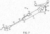
- FIG. 7illustrates a balloon dilation catheter 10 according to another embodiment.
- a tracking element 60is located on the handle 12 of the balloon dilation catheter 10.
- the tracking element 60may include an antenna, transmitter, optical reflectors, or the like that communicates a wireless signal that is then received and processed to determine the orientation and/or positioning of the balloon dilation catheter 10.
- more than one tracking element 60may be disposed on the balloon dilation catheter 10.
- Data regarding the orientation and/or positioning of the balloon dilation catheter 10may then be processed and displayed on the display for viewing by the physician. For example, image guided surgery is becoming increasingly commonplace, permitting physicians to review real time actual or virtual images of a particular device within a subject during a surgical procedure.
- U.S. Patent Nos. 5,391 ,199 and 5,443,489which are incorporated by reference, describe a system wherein coordinates of an intrabody probe are determined using one or more field sensors such as, Hall effect devices, coils, or antennas that are carried on the probe.
- U.S. Patent Application Publication No. 2002-0065455which is also incorporated by reference, describes a system that is capable of generating a six-dimensional position and orientation representation of the tip of a catheter using a combination of sensor and radiation coils.
- U.S. Patent Application Publication No. 2008-0269596which is also incorporated by reference, describes yet another monitoring system that has particular applications in orthopedic procedures. Commercial systems such as the LANDMARX Element (Medtronic Xomed Products, Inc., Jacksonville, FL) are available for use in conjunction with ENT procedures.
- the tracking element 60permits accurate tracking of the distal end 20 of the balloon dilation catheter 10 such that an image of distal portion of the balloon dilation catheter 10 may be superimposed on a patient's anatomical imagery.
- a previously conducted computed tomography (CT) scan of the patientmay be used to generate a visual image of the patient's anatomical regions of interest.
- CTcomputed tomography
- IGSimage guided surgery
- the balloon dilation catheter 10 illustrated in FIG. 7may be integrated and/or used with the balloon dilation catheter 10.
- CT guidanceto position the balloon dilation catheter 10 is preferred because the device may be positioned by the operator with just a single hand, while viewing the CT image interface (e.g., display) at the same time the handle 12 is manipulated.
- the balloon dilation catheter 10may be initially positioned using and endoscope or other visualization tool.
- a conventional "Hopkins rod" endoscope(not shown) may be manipulated alongside the balloon dilation catheter 10 to aid in placement.
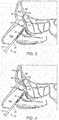
- FIGS. 8-12illustrate various cross-sectional views (sagittal plane) of the frontal sinus of a subject undergoing treatment with a balloon dilation catheter 10.
- the cross-sectional viewsillustrate the nasal passageway 100, the frontal recess 102, and the frontal sinus cavity 104.
- the balloon dilation catheter 10is inserted into the nasal passageway 100 with the advancer knob 32 in the retracted position (e.g., as illustrated in FIG. 1 , 2A, 2B ) such that the shaft 30 and balloon 36 are also retracted proximally.
- the balloon 36is in a deflated state as seen in FIG. 8 .
- the curved portion 16 of the inner guide member 14is then positioned within the frontal recess 102 of the subject as seen in FIG. 8 .
- This positioning of the inner guide member 14may be accomplished under endoscopic visualization using a conventional endoscope such as a Hopkins rod-type endoscope that is positioned alongside the balloon dilation catheter 10.
- the inner guide member 14may be positioned using IGS techniques that track the position of the balloon dilation catheter 10 using one or more tracking elements 60 as illustrated, for instance, in the embodiment of FIG. 7 .
- the inner guide member 14may be advanced under guidance from CT imaging.
- confirmation of accurate positioning of the inner guide member 14 within the frontal recess 102may be accomplished by placement of a fluoroscopically visible guide wire 64 through the lumen 18 of the inner guide member 14.
- the guide wire 64may be inserted into the lumen 18 via the port 22. Under fluoroscopic visualization, the guide wire 64 can be seen to advance into the frontal sinus cavity 104 once the inner guide member 14 is positioned properly within the frontal recess 102. If the guide wire 64 does not advance into the frontal sinus cavity 104, the balloon dilation catheter 10 is re-positioned and confirmation is subsequently attempted.
- the guide wire 64could be a light emitting guide wire such as that disclosed in U.S.
- the guide wire 64is optional as the inner guide member 14 may be placed without the aid or need for the same.
- the guide wire 64could be positioned in the frontal sinus initially, prior to placement of the balloon catheter 10.
- the advancer knob 32is advanced in the distal direction (arrow A of FIG. 3A ) thereby advancing the shaft 30 and attached balloon 36 into the frontal recess 102. This is illustrated in FIG. 10 .
- the balloon 36is inflated as illustrated in FIG. 1 1 .
- Inflationis accomplished by coupling an inflation device (not shown) to the port 38.
- the inflation devicemay include a syringe or the like that is depressed to infuse a fluid into the inflation lumen 48 which then passes into the interior of the balloon 36 to effectuate expansion of the balloon 36 to the state illustrated in FIG. 1 1 .
- Pressures typically used to accomplish widening or remodeling of the frontal recess 102are within the range of about 3 atmospheres to about 12 atmospheres.
- the balloon 36may be inflated only a single time or, alternatively, the balloon 36 may be inflated, deflated, and inflated again a plurality of times in order to achieve the desired degree of widening. Each inflation step may be performed after positioning the balloon 36 in a different position within the frontal recess 102.
- the balloon 36is deflated and removed as illustrated in FIG. 12 .
- the widened frontal recess 102 illustrated in FIG. 12is believed to restore the drainage and aeration function and health of the frontal sinus cavity 104.
- Deflation of the balloon 36is accomplished by reducing the fluid pressure within the interior of the balloon 36.
- the plunger of a syringe or the like that is fluidically coupled to the port 38may be withdrawn to remove fluid from the interior of the balloon 36.
- the balloon dilation catheter 10can then be withdrawn proximally from the nasal passageway 100.
- treatment of one or both frontal sinuses 104 as described abovemay be adequate.
- additional sinusesmay need to be treated, particularly the maxillary and/or anterior ethmoid sinuses.
- a combination proceduremay be well suited.
- the maxillary and/or anterior ethmoid sinusescan be treated with a system such as described in U.S. Patent No. 7,520,876 and U.S. Patent Application Publication No. 2008-0172033 , commercially available as the FinESS system by Entellus Medical, Inc. of Maple Grove, MN.
- other sinusescould be treated more conventionally using surgical techniques such as, for instance, functional endoscopic sinus surgery (FESS).
- FESSfunctional endoscopic sinus surgery
- the sphenoid and/or maxillary sinus outflow tractscould be dilated with the embodiment of the balloon catheter 10 described above. It is also contemplated that the balloon catheter 10, particularly the embodiment of FIG. 7 with a suitable IGS device is incorporated, and with an appropriate shape for the inner support member 14, preferably straight as illustrated in FIG. 6C , could be used to dilate the maxillary sinus outflow tract via the canine fossa route. Suitable access tools are described in co-pending U.S. Patent Application No. 12/038,719 , which is incorporated by reference herein. This could be performed without need for additional endoscopic visualization, permitting treatment through a relatively small diameter access passageway into the sinus cavity in the region of the canine fossa. A small endoscope (not shown) could be utilized, if desired, through the lumen 18 of the inner support member 14 to further aid in visualization of the maxillary sinus outflow tract.
Landscapes
- Health & Medical Sciences (AREA)
- Life Sciences & Earth Sciences (AREA)
- Engineering & Computer Science (AREA)
- Heart & Thoracic Surgery (AREA)
- Surgery (AREA)
- Veterinary Medicine (AREA)
- General Health & Medical Sciences (AREA)
- Biomedical Technology (AREA)
- Public Health (AREA)
- Animal Behavior & Ethology (AREA)
- Medical Informatics (AREA)
- Molecular Biology (AREA)
- Nuclear Medicine, Radiotherapy & Molecular Imaging (AREA)
- Pulmonology (AREA)
- Hematology (AREA)
- Anesthesiology (AREA)
- Robotics (AREA)
- Biophysics (AREA)
- Otolaryngology (AREA)
- Oral & Maxillofacial Surgery (AREA)
- Dentistry (AREA)
- Vascular Medicine (AREA)
- Child & Adolescent Psychology (AREA)
- Surgical Instruments (AREA)
- Media Introduction/Drainage Providing Device (AREA)
Abstract
Description
- The field of the invention generally relates to balloon inflation devices and methods. More particularly, the field of the invention relates to balloon dilation devices and methods for the treatment of sinusitis.
- Sinusitis is a condition affecting over 35 million Americans, and similarly large populations in the rest of the developed world. Sinusitis occurs when one or more of the four paired sinus cavities (i.e., maxillary, ethmoid, frontal, sphenoid) becomes obstructed, or otherwise has compromised drainage. Normally the sinus cavities, each of which are lined by mucosa, produce mucous which is then moved by beating cilia from the sinus cavity out to the nasal cavity and down the throat. The combined sinuses produce approximately one liter of mucous daily, so the effective transport of this mucous is important to sinus health.
- Each sinus cavity has a drainage pathway or outflow tract opening into the nasal passage. This drainage passageway can include an ostium, as well as a "transition space" in the region of the ostia, such as the "frontal recess," in the case of the frontal sinus, or an "ethmoidal infundibulum," in the case of the maxillary sinus. When the mucosa of one or more of the ostia or regions near the ostia become inflamed, the egress of mucous is interrupted, setting the stage for an infection and/or inflammation of the sinus cavity, i.e., sinusitis. Though many instances of sinusitis may be treatable with appropriate medicates, in some cases sinusitis persists for months or more, a condition called chronic sinusitis, and may not respond to medical therapy. Some patients are also prone to multiple episodes of sinusitis in a given period of time, a condition called recurrent sinusitis.
- Balloon dilation has been applied to treat constricted sinus passageways for the treatment of sinusitis. These balloon dilation devices typically involve the use of an inflatable balloon located at the distal end of a catheter such as a balloon catheter. Generally, the inflatable balloon is inserted into the constricted sinus passageway in a deflated state. The balloon is then expanded to open or reduce the degree of constriction in the sinus passageway being treated to facilitate better sinus drainage and ventilation. At the same time most, if not all, of the functional mucosal tissue lining of the sinuses and their drainage passageways are preserved.
- Exemplary devices and methods particularly suited for the dilation of anatomic structures associated with the maxillary and anterior ethmoid sinuses are disclosed, for example, in
U.S. Patent No. 7,520,876 andU.S. Patent Application Publication No. 2008-0172033 . Other systems have been described for the treatment of various other sinuses including the frontal sinus. For example,U.S. Patent Application Publication No. 2008-0097295 discloses a frontal sinus guide catheter (FIG. 6B ) and method of treating the frontal sinuses (e.g.,FIGS. 8B-8C ).U.S. Patent Application Publication No. 2008-0125626 discloses another guide device (e.g.,FIGS. 10C and 10C ) for transnasal access to the frontal sinuses for treatment. - In a first embodiment of the invention, a balloon dilation catheter includes a substantially rigid inner guide member and a movable shaft coupled to a balloon that is slidably mounted on the substantially rigid inner guide member. To treat a drainage pathway of a sinus cavity (e.g., frontal sinus cavity) of a subject using the balloon dilation catheter, the substantially rigid inner guide member is advanced into a drainage pathway of the subject via a nasal passageway. The shaft and balloon are then advanced in a distal direction over the substantially rigid inner guide member to place the balloon in the drainage pathway. This enables the balloon to track over the inner guide member. The balloon is inflated to expand or otherwise remodel the drainage pathway. Where the sinus cavity is the frontal sinus cavity the drainage pathway is the frontal recess.
- In another aspect of the invention, a device for dilating the outflow tract of a sinus cavity includes a substantially rigid inner guide member having a proximal end and a distal end and a shaft coupled to a balloon, the shaft having a first lumen along at least a portion thereof containing the substantially rigid inner guide member, the shaft having a second lumen operatively coupled to the interior of the balloon. A handle is disposed along a proximal portion of the substantially rigid inner guide member, the handle including a moveable knob operatively coupled to the shaft, wherein distal advancement of the knob advances the shaft and balloon over the substantially rigid inner guide in a distal direction.
- The following items are also disclosed:
- 1. A device for dilating the outflow tract of a sinus cavity comprising: a metallic inner member having a proximal end and a distal end; a shaft coupled to a balloon, the shaft having a first lumen along at least a portion thereof containing the metallic inner member, the shaft having a second lumen operatively coupled to the interior of the balloon; and a handle disposed along a proximal portion of the metallic inner member, the handle comprising a moveable knob operatively coupled to the shaft, wherein distal advancement of the knob advances the shaft and balloon over the metallic inner member in a distal direction.
- 2. The device of item 1, wherein the metallic inner member comprises a lumen along a length thereof.
- 3. The device of item 2, further comprising a flexible wire dimensioned for slidable movement within the lumen of the metallic inner member.
- 4. The device of item 1, wherein the distal end of the metallic inner member comprises a curved portion.
- 5. The device of item 4, wherein the distal end of the curved portion terminates in a straight segment.
- 6. The device of item 4, wherein the curved portion has a radius of curvature of between 0.25 inches and 1.5 inches.
- 7. The device of item 1, wherein the distal end of the metallic inner member comprises a bulbous tip.
- 8. The device of item 1, wherein the distal end of the metallic inner member comprises a malleable portion.
- 9. The device of item 1, wherein the shaft is helically wrapped about a length of the metallic inner member along a portion of the handle.
- 10. The device of item 1, further comprising at least one tracking element disposed at the handle.
- 11. The device of item 1, wherein the metallic inner member is replaceable within the handle.
- 12. The device of item 1, wherein the handle includes a slot and a portion of the knob is slidably disposed within the slot.
- 13. The device of
item 12, wherein the slot is between 1 and 2 inches in length. - 14. The device of item 1, wherein the handle includes a stop.
- 15. The device of item 1, wherein the metallic inner member is a stainless steel tube having an inner diameter in the range of between 0.020 inches and 0.050 inches and a wall thickness in the range of between 0.005 inches and 0.020 inches.
FIG. 1 illustrates a perspective view of a balloon dilation catheter according to one embodiment.FIG. 2A illustrates a side view of a balloon dilation catheter ofFIG. 1 . The advancer knob is illustrated in the retracted, proximal position.FIG. 2B illustrates a cross-sectional view of the balloon dilation catheter ofFIG. 2A .FIG. 3A illustrates a side view of a balloon dilation catheter ofFIG. 1 . The advancer knob is illustrated in the advanced, distal position.FIG. 3B illustrates a cross-sectional view of the balloon dilation catheter ofFIG. 3A .FIG. 4 is a cross-sectional view of the handle portion (dashed line portion) ofFIG. 3B .FIG. 5A is a cross-sectional view of the balloon dilation catheter taken along the line A-A' ofFIG. 2B .FIG. 5B is a cross-sectional view of the balloon dilation catheter taken along the line B-B' ofFIG. 4 .FIG. 6A is a side view of an inner guide member according to one embodiment.FIG. 6B is a side view of an inner guide member according to another embodiment.FIG. 6C is a side view of an inner guide member according to another embodiment.FIG. 7 illustrates a perspective view of a balloon dilation catheter according to another embodiment.FIG. 8 illustrates a cross-sectional view of the frontal sinus of a subject with the inner guide member of the balloon dilation catheter being advanced into the subject's frontal recess.FIG. 9 illustrates a cross-sectional view of the frontal sinus of a subject with the inner guide member of the balloon dilation catheter being positioned in the subject's frontal recess. A guide wire is shown advanced through the catheter and into the subject's frontal sinus cavity.FIG. 10 illustrates a cross-sectional view of the frontal sinus of a subject with the balloon (in a deflated state) and shaft being advanced into the subject's frontal recess.FIG. 1 1 illustrates a cross-sectional view of the frontal sinus of a subject with the balloon ofFIG. 10 in an inflated state to thereby widen and remodel the frontal recess.FIG. 12 illustrates a cross-sectional view of the frontal sinus of a subject after the frontal sinus has been widened and the balloon inflation catheter withdrawn.FIG. 1 illustrates one embodiment of aballoon dilation catheter 10 that is particularly suited for treatment of the outflow tract (frontal sinus ostium and frontal recess) of the frontal sinus of a subject. Theballoon dilation catheter 10 includes ahandle 12 that is configured to be gripped or otherwise manipulated by the operator. An elongate-shapedinner guide member 14 extends longitudinally from thehandle 12 in a distal direction. Theinner guide member 14 is formed of a suitably rigid material such as stainless steel hypotube. Theinner guide member 14 projects or otherwise extends distally from thehandle 12 for a pre-determined distance. Theinner guide member 14 may be pre-shaped to have a curveddistal portion 16 as is illustrated inFIGS. 1 ,2A ,2B ,3A ,3B ,6A ,6B ,7 ,8, and 9 . For example, the nature and degree of the curveddistal portion 16 may be configured to match with the frontal sinus outflow tract or frontal recess.- Alternatively, the
inner guide member 14 may have some degree of malleability such that the user may bend or impart some desired shape or configuration to the distal end of theinner guide member 14. As explained herein in more detail, theinner guide member 14 may include an optional lumen 18 (best illustrated inFIG. 5A ) that extends the length of theinner guide member 14. In particular, theinner guide member 14 and the containedlumen 18 may extend from adistal end 20 to a proximal end 21 (best seen inFIGS. 2B and3B ) that interfaces with a sealed arrangement with aport 22 disposed at aproximal end 24 of thehandle 12. Theport 22 may be configured with a conventional interface such as a Luer connector. Theport 22 may be used as an aspiration port or a delivery port for fluids and/or medicaments, or for introduction of a guide wire. Still referring toFIG. 1 , ashaft 30 is mounted about the periphery of theinner guide member 14. In particular, theshaft 30 is dimensioned to slide over theinner guide member 14 in response to actuation of anadvancer knob 32 located on thehandle 12. Theadvancer knob 32 is moveable along aslot 42 contained in a surface of thehandle 12. Adistal end 34 of theshaft 30 includes aballoon 36 that is configured to be selectively inflated or deflated as explained herein. During use, theinner guide member 14 is manipulated and advanced across or into the anatomical space of interest. Theshaft 30 as well as the attachedballoon 36 is illustrated in a retracted state inFIG. 1 . WhileFIG. 1 illustrates theballoon 36 in an inflated state for better illustration, theballoon 36 is typically in a deflated state when theshaft 30 is in the proximal position as illustrated inFIGS. 2A and 2B . After theinner guide member 14 is properly positioned, the user actuates theadvancer knob 32 by sliding the same in the distal direction which, in turn, advances theshaft 30 andballoon 36 in a distal direction over the pre-placedinner guide member 14. Once theballoon 36 is properly placed, theballoon 36 is inflated. Inflation of theballoon 36 is accomplished using an inflation device (not shown) that is coupled to aport 38 located at theproximal end 24 of thehandle 12. One exemplary inflation device that may be used in connection with theballoon dilation catheter 10 is described inU.S. Patent Application No. 12/372,691 , which is incorporated by reference as if set forth fully herein. Of course, other inflation devices may also be used. Aninflation lumen 48 contained within the shaft 30 (described in more detail below), fluidically couples theport 38 to an interior portion of theballoon 36. - Still referring to
FIG. 1 , anoptional support member 40 in the form of a tube may be located about the external periphery of a portion of theshaft 30 to impart further stiffness to theballoon dilation catheter 10. The particular length of thesupport member 40 may vary depending on the application and may extend along some or all or theshaft 30. Thesupport member 40 may be made of a metallic material such as stainless steel hypotube that is secured to theshaft 30. Thesupport member 40 may be welded or bonded along a length of theshaft 30. Generally, thesupport member 40 does not cover the helical portion (described in detail below) of theshaft 30 that is contained within thehandle 12. FIGS. 2A and 2B illustrate, respectively, side and cross-sectional views of theballoon dilation catheter 10 with theadvancer knob 32 and thusballoon 36 in the proximal position. In actual use, as explained herein, theballoon 36 is typically in a deflated state when theadvancer knob 32 is the proximal position as illustrated inFIGS. 2A and 2B . As best seen inFIG. 1 , theadvancer knob 32 is slidably disposed along a length of thehandle 12 inside aslot 42. Theadvancer knob 32 is thus able to slide back and forth in the distal/proximal direction along the length of theslot 42. Theslot 42 may incorporate a stop or the like (not shown) to prevent theballoon 36 from being advance too far along the length of theinner guide member 14. The length of theslot 42 may be varied in different devices to adjust the length at which theballoon 36 may be advanced. Generally, theslot 42 has a length within the range of about 1 inch to about 2 inches although other dimensions may fall within the scope of the invention.- As seen in
FIG. 2B , theadvancer knob 32 may be directly coupled to thesupport member 40 that is mounted on theshaft 30. Alternatively, theadvancer knob 32 may be coupled directly to theshaft 30. Theadvancer knob 32 may be configured or otherwise shaped to enable a finger of the user (e.g., index finger or thumb) to easily advance or retract theknob 32 along theslot 42 contained in thehandle 12. FIGS. 3A and 3B illustrate, respectively, side and cross-sectional views of theballoon dilation catheter 10 with theadvancer knob 32 and thusballoon 36 in the distal position. Thus, unlike the configurations ofFIGS. 2A and 2B , theadvancer knob 32 is located at or near thedistal end 26 of thehandle 12. Advancement of theadvancer knob 32 also slides theshaft 30 and attachedballoon 36 in a distal direction (arrow A inFIG. 3A ) along theinner guide member 14. Theballoon 36 thus is positioned at or adjacent to thedistal end 20 of theinner guide member 14. Theballoon dilation catheter 10 may be designed such that theadvancer knob 32 may be positioned at either the proximal or distal extremes as illustrated inFIGS. 2A, 2B ,3A, 3B . Alternatively, theadvancer knob 32 may be positioned somewhere in between the two extremes. For example, the optimal position of theballoon 36 may be accomplished by sliding theadvancer knob 32 some fraction (e.g., 3/4) of the full distance of theslot 42.- Referring to
FIGS. 2B and3B , theinner guide member 14 of theballoon dilation catheter 10 extends from adistal end 20 to aproximal end 21 that terminates in a sealed interface with aport 22 disposed at aproximal end 24 of thehandle 12. Theinner guide member 14 optionally includes alumen 18 disposed therein that may be used to provide aspiration functionality via an aspiration device (not shown) coupled toport 22. Aspiration functionality permits the removal of blood and other secretions. This makes it easier to visualize the placement of theballoon dilation catheter 10. Theinner guide member 14 is advantageously rigid to enable theballoon dilation catheter 10 to be positioned without the need of a separate guiding catheter or guide wire in most, if not all, instances. - The
inner guide member 14 may have a length of about 7 inches to about 1 1 inches from thedistal end 20 to theproximal end 21 when loaded into thehandle 12, although other dimensions may be used. Theinner guide member 14 may be formed from stainless steel hypotube having an inner diameter in the range of about 0.020 inch to about 0.050 inch, and more preferably between about 0.036 inch and 0.040 inch, with a wall thickness within the range of about 0.005 inch to about 0.020 inch, and more preferably between about 0.008 inch to about 0.012 inch. The curveddistal portion 16 of theinner guide member 14 may be formed right to thedistal end 20 and may have a radius of curvature of about 0.25 inch to about 1.5 inch, and more preferably about 0.75 to about 1 .25 inch. - The length of the
inner guide member 14 that projects distally from the distal-most portion of theballoon 36 is about 0.5 inch to about 2.0 inch, and more preferably, about 0.8 inch to about 1.2 inch when theballoon 36 is in the fully retracted state (e.g., illustrated inFIGS. 2A and 2B ). As seen inFIGS. 1 ,2A ,2B ,3A, 3B ,6A-6C ,7-11 , thedistal end 20 of theinner guide member 14 may incorporate an optionalbulbous tip 44 in order to make thedistal end 20 more atraumatic. Thebulbous tip 44 further serves to limit forward movement of theballoon 36 and attachedshaft 30 when they are advanced distally. The outer diameter of thetip 44 is preferably between about 1 mm and about 3 mm. - The
balloon 36 is mounted on theshaft 30 so as to form a fluidic seal between the two components. Theballoon 36 may be bonded to the shaft using a weld, adhesive, or the like. Alternately, theballoon 36 may be secured to the shaft using a mechanical connection. Generally, any technique known to those skilled in the art may be used to secure to theballoon 36 to theshaft 30. Given that theballoon 36 is secured directly to theshaft 30, both structures are slidably mounted over theinner guide member 14. Theballoon 36 generally takes on a cylindrical- shape when inflated. While not limited to specific dimensions, theinflated balloon 36 has a diameter within the range of about 3 mm to about 9 mm, and more preferably a diameter within the range of about 5 to about 7 mm when inflated. The length of theballoon 36 may generally fall within the range of about 10 mm to 25 mm although other lengths may be used. Both theshaft 30 and theballoon 36 are preferably formed of high strength but flexible polymeric materials such as polyamides (e.g., Nylon), PEBAX or the like. Theballoon 36 may be "blow molded" to a relatively thin wall thickness, and capable of holding relatively high pressures from about 6 atmospheres to about 20 atmospheres of inflation pressure. Theballoon 36 is inflated using a fluid which is typically a liquid such as water or saline. - Referring now to
FIG. 4 , a magnified, cross-sectional view of a portion of thehandle 12 is illustrated. At theproximal end 24 of thehandle 12 are locatedports port 22 may be configured with a conventional interface such as a Luer connector or any other connector known to those skilled in the art. Theport 22 may be integrally formed with thehandle 12 or, alternatively, theport 22 may be a separate structure that is secured to thehandle 12 during assembly. As seen inFIG. 4 , theproximal end 21 of theinner guide member 14 forms a sealing arrangement with theport 22. As explained herein, theport 22 may be used as an aspiration port or a delivery port for fluids and/or medicaments. FIG. 4 also illustratesport 38 which may be constructed in the same or similar manner asport 22 as described above. Theport 38 is fluidically coupled to theinflation lumen 48 in theshaft 30. In this regard, inflation fluid from an inflation device (not shown) is able to pass through theport 38 and into theinflation lumen 48 of theshaft 30. Theport 38 may be configured with a conventional interface such as a Luer connector. The fluid then is able to travel along the length of theshaft 30 via thelumen 48 where the fluid enters the interior of theballoon 36. The inflation fluid is thus able to inflate theballoon 36 upon actuation of the inflation device.- As best seen in
FIG. 4 , a portion of thehandle 12 includes a recessedregion 50 that receives both theinner guide member 14 and theshaft 30. In the recessedregion 50 of thehandle 12, theshaft 30 is helically wrapped around the outer periphery of theinner guide member 14 forming ahelical portion 52. Thehelical portion 52 facilitates the distal advancement and proximal retraction of theshaft 30 and attachedballoon 36 along theinner guide member 14 yet still maintains fluid communication with theport 38. Thehelical portion 52 of theshaft 30, which is located proximal to theadvancer knob 32 is in the shape of a helix that wraps around theinner guide member 14 and is configured to elongate and contract upon movement of theadvancer knob 32.FIG. 4 illustrates the state of thehelical portion 52 after theadvancer knob 32 has been advanced distally. Thus, in the extended state, the length of thehelical portion 52 traverses much if not all of the recessedregion 50. Contrast this withFIG. 2B which illustrates thehelical portion 52 compressed to the proximal portion of the recessedregion 50 because theadvancer knob 32 is the in proximal position. Thus, thehelical portion 52 is thus able to expand or compress much in the way that a spring does in response to a tensile or compressive load. One or both of theinner guide member 14 and thehelical portion 52 of theshaft 30 may be optionally coated or lined with a lubricious coating to prevent the contact surfaces from any unwanted fhctional binding or the like. - The
helical portion 52 of theshaft 30 may be formed by "skiving" away a portion of theshaft 30.FIG. 5A illustrates a cross-sectional view of theshaft 30,inner support guide 14, andsupport member 40 along the line A-A' ofFIG. 2B . As seen inFIG. 2B , this area is distal to where thehelical portion 52 of theshaft 30 is located. Referring now toFIG. 5A , theshaft 30 includes arider lumen 54 that is dimensioned to have a diameter that is slightly larger than the outer diameter of theinner support guide 14. Therider lumen 54 thus enables theshaft 30 to advance and retract over theinner support guide 14 in a close-fit arrangement. The outer diameter of theshaft 30 may generally fall within the range of about .050 inch to about .1 10 inch or within the range of about .070 inch to about .100 inch. One or both of the exterior surface of theinner guide member 14 and the interior surface of therider lumen 54 may be optionally coated with a lubricious coating to reduce fhctional contact forces.FIG. 5B illustrates a cross-sectional view of theinner support guide 14 and thehelical portion 52 of theshaft 30 taken along the line B-B' ofFIG. 4 . As seen inFIG. 5B , a portion of theshaft 30 that includes therider lumen 54 is skived away. The result is that a single lumen (inflation lumen 48) remains in theshaft 30 that is helically wrapped about theinner support guide 14. FIGS. 6A-6C illustrate various embodiments of aninner guide member 14. Theinner guide member 14 may have a variety of shapes and configurations depending on the particular application or patient. The different shapes of theinner guide member 14 may be factory-formed in a particular shape and offered as a different model as fully assembled or, alternatively, theinner guide member 14 may be replaceable or modular elements that could slide inside therider lumen 54 and inserted into theport 22 in a press-fit type sealing arrangement. In yet another alternative, the shapes could represent desirable shapes that a malleableinner guide member 14 could be formed into by the user to better fit a particular application or subject's anatomy.FIG. 6A illustrates aninner guide member 14 that includes a curveddistal portion 16 that terminates in astraight segment 46. In the embodiment ofFIG. 6A , the curve in the curveddistal portion 16 is pronounced and turns back on itself in the shape of a "U" in which thedistal end 20 turns back in retrograde fashion. This embodiment may be useful to treat hard to reach ostia or other structures, e.g., the maxillary ostium or the infundibulum via a transnasal route, if the nasal anatomy will allow for a trans-nasal approach. WhileFIG. 6A illustrates a "U" shaped curve, other degrees of curvature are contemplated.FIG. 6B illustrates aninner guide member 14 according to another embodiment. In this embodiment, the curveddistal portion 16 also terminates in astraight segment 46 although the radius of curvature is less pronounced. In this embodiment, thestraight segment 46 may have a length within the range of about 8 mm to about 10 mm although other lengths may be used. It is believed that this embodiment is particularly suited for most frontal recess anatomy.FIG. 6C illustrates an embodiment in which theinner guide member 14 is substantially straight. This later embodiment may be particularly suited for treating the sphenoids of the subject, or straightforward frontal recess anatomy.FIG. 7 illustrates aballoon dilation catheter 10 according to another embodiment. In this embodiment, atracking element 60 is located on thehandle 12 of theballoon dilation catheter 10. The trackingelement 60 may include an antenna, transmitter, optical reflectors, or the like that communicates a wireless signal that is then received and processed to determine the orientation and/or positioning of theballoon dilation catheter 10. In certain embodiments, more than onetracking element 60 may be disposed on theballoon dilation catheter 10. Data regarding the orientation and/or positioning of theballoon dilation catheter 10 may then be processed and displayed on the display for viewing by the physician. For example, image guided surgery is becoming increasingly commonplace, permitting physicians to review real time actual or virtual images of a particular device within a subject during a surgical procedure.- For example,
U.S. Patent Nos. 5,391 ,199 and5,443,489 , which are incorporated by reference, describe a system wherein coordinates of an intrabody probe are determined using one or more field sensors such as, Hall effect devices, coils, or antennas that are carried on the probe.U.S. Patent Application Publication No. 2002-0065455 , which is also incorporated by reference, describes a system that is capable of generating a six-dimensional position and orientation representation of the tip of a catheter using a combination of sensor and radiation coils.U.S. Patent Application Publication No. 2008-0269596 , which is also incorporated by reference, describes yet another monitoring system that has particular applications in orthopedic procedures. Commercial systems such as the LANDMARX Element (Medtronic Xomed Products, Inc., Jacksonville, FL) are available for use in conjunction with ENT procedures. - In the embodiment of
FIG. 7 , the trackingelement 60 permits accurate tracking of thedistal end 20 of theballoon dilation catheter 10 such that an image of distal portion of theballoon dilation catheter 10 may be superimposed on a patient's anatomical imagery. For example, a previously conducted computed tomography (CT) scan of the patient may be used to generate a visual image of the patient's anatomical regions of interest. Based on the location of thetracking element 60, an image guided surgery (IGS) system can then superimpose an image of theballoon dilation catheter 10 onto the image to better enable the physician to manipulate and orient theballoon dilation catheter 10. - Other commercial systems may also be used in connection with the
balloon dilation catheter 10 illustrated inFIG. 7 . For example, the INSTATRAK 3500 Plus - ENT from GE Healthcare, Chalfont St. Giles, United Kingdom may be integrated and/or used with theballoon dilation catheter 10. The use of CT guidance to position theballoon dilation catheter 10 is preferred because the device may be positioned by the operator with just a single hand, while viewing the CT image interface (e.g., display) at the same time thehandle 12 is manipulated. Optionally, theballoon dilation catheter 10 may be initially positioned using and endoscope or other visualization tool. For instance, a conventional "Hopkins rod" endoscope (not shown) may be manipulated alongside theballoon dilation catheter 10 to aid in placement. FIGS. 8-12 illustrate various cross-sectional views (sagittal plane) of the frontal sinus of a subject undergoing treatment with aballoon dilation catheter 10. The cross-sectional views illustrate thenasal passageway 100, thefrontal recess 102, and thefrontal sinus cavity 104. Referring toFIG. 8 , theballoon dilation catheter 10 is inserted into thenasal passageway 100 with theadvancer knob 32 in the retracted position (e.g., as illustrated inFIG. 1 ,2A, 2B ) such that theshaft 30 andballoon 36 are also retracted proximally. In addition, theballoon 36 is in a deflated state as seen inFIG. 8 . Thecurved portion 16 of theinner guide member 14 is then positioned within thefrontal recess 102 of the subject as seen inFIG. 8 . This positioning of theinner guide member 14 may be accomplished under endoscopic visualization using a conventional endoscope such as a Hopkins rod-type endoscope that is positioned alongside theballoon dilation catheter 10. Alternatively, theinner guide member 14 may be positioned using IGS techniques that track the position of theballoon dilation catheter 10 using one ormore tracking elements 60 as illustrated, for instance, in the embodiment ofFIG. 7 . For instance, theinner guide member 14 may be advanced under guidance from CT imaging.- Referring now to
FIG. 9 , confirmation of accurate positioning of theinner guide member 14 within thefrontal recess 102 may be accomplished by placement of a fluoroscopicallyvisible guide wire 64 through thelumen 18 of theinner guide member 14. Theguide wire 64 may be inserted into thelumen 18 via theport 22. Under fluoroscopic visualization, theguide wire 64 can be seen to advance into thefrontal sinus cavity 104 once theinner guide member 14 is positioned properly within thefrontal recess 102. If theguide wire 64 does not advance into thefrontal sinus cavity 104, theballoon dilation catheter 10 is re-positioned and confirmation is subsequently attempted. As an alternative to a fluoroscopicallyvisible guide wire 64, theguide wire 64 could be a light emitting guide wire such as that disclosed inU.S. Patent Application Publication No. 2007-0249896 , which is incorporated by reference herein. Of course, theguide wire 64 is optional as theinner guide member 14 may be placed without the aid or need for the same. Alternatively, theguide wire 64 could be positioned in the frontal sinus initially, prior to placement of theballoon catheter 10. - Now referring to
FIG. 10 , once thecurved portion 16 of theinner guide member 14 is properly positioned, theadvancer knob 32 is advanced in the distal direction (arrow A ofFIG. 3A ) thereby advancing theshaft 30 and attachedballoon 36 into thefrontal recess 102. This is illustrated inFIG. 10 . After theballoon 36 is positioned in thefrontal recess 102, theballoon 36 is inflated as illustrated inFIG. 1 1 . Inflation is accomplished by coupling an inflation device (not shown) to theport 38. The inflation device may include a syringe or the like that is depressed to infuse a fluid into theinflation lumen 48 which then passes into the interior of theballoon 36 to effectuate expansion of theballoon 36 to the state illustrated inFIG. 1 1 . Pressures typically used to accomplish widening or remodeling of thefrontal recess 102 are within the range of about 3 atmospheres to about 12 atmospheres. Theballoon 36 may be inflated only a single time or, alternatively, theballoon 36 may be inflated, deflated, and inflated again a plurality of times in order to achieve the desired degree of widening. Each inflation step may be performed after positioning theballoon 36 in a different position within thefrontal recess 102. - After the
frontal recess 102 has been widened or otherwise remodeled, theballoon 36 is deflated and removed as illustrated inFIG. 12 . The widenedfrontal recess 102 illustrated inFIG. 12 is believed to restore the drainage and aeration function and health of thefrontal sinus cavity 104. Deflation of theballoon 36 is accomplished by reducing the fluid pressure within the interior of theballoon 36. For example, the plunger of a syringe or the like that is fluidically coupled to theport 38 may be withdrawn to remove fluid from the interior of theballoon 36. Theballoon dilation catheter 10 can then be withdrawn proximally from thenasal passageway 100. - In certain patients, treatment of one or both
frontal sinuses 104 as described above may be adequate. In other patients, additional sinuses may need to be treated, particularly the maxillary and/or anterior ethmoid sinuses. In such patients, a combination procedure may be well suited. The maxillary and/or anterior ethmoid sinuses can be treated with a system such as described inU.S. Patent No. 7,520,876 andU.S. Patent Application Publication No. 2008-0172033 , commercially available as the FinESS system by Entellus Medical, Inc. of Maple Grove, MN. Alternatively, other sinuses could be treated more conventionally using surgical techniques such as, for instance, functional endoscopic sinus surgery (FESS). - Also, the sphenoid and/or maxillary sinus outflow tracts could be dilated with the embodiment of the
balloon catheter 10 described above. It is also contemplated that theballoon catheter 10, particularly the embodiment ofFIG. 7 with a suitable IGS device is incorporated, and with an appropriate shape for theinner support member 14, preferably straight as illustrated inFIG. 6C , could be used to dilate the maxillary sinus outflow tract via the canine fossa route. Suitable access tools are described in co-pendingU.S. Patent Application No. 12/038,719 , which is incorporated by reference herein. This could be performed without need for additional endoscopic visualization, permitting treatment through a relatively small diameter access passageway into the sinus cavity in the region of the canine fossa. A small endoscope (not shown) could be utilized, if desired, through thelumen 18 of theinner support member 14 to further aid in visualization of the maxillary sinus outflow tract. - While embodiments of the present invention have been shown and described, various modifications may be made without departing from the scope of the present invention. The invention, therefore, should not be limited, except to the following claims, and their equivalents.
Claims (15)
- A balloon dilation catheter (10) comprising:a handle (12) configured to be gripped by an operator;a substantially rigid inner guide member (14) extending longitudinally from the handle (12) in a distal direction, the substantially rigid inner guide member (14) having a proximal end (21), a distal end (20), and a lumen (18) extending along a length thereof and terminating at the distal end (20); anda shaft (30) coupled to a balloon (36), wherein the shaft (30) includes a first lumen (54) along at least a portion thereof containing the substantially rigid inner guide member (14), wherein the shaft (30) includes a second lumen (48) operatively coupled to an interior of the balloon (36), and wherein the shaft (30) and the balloon (36) are slidably mounted over the substantially rigid inner guide member (14) such that the shaft (30) and the balloon (36) are configured to be advanced distally with respect to the substantially rigid inner guide member (14) and the handle (12).
- The balloon dilation catheter (10) of claim 1, wherein the shaft (30) defines a rider lumen (54) and the substantially rigid inner guide member (14) extends through the rider lumen (54) when the shaft (30) is in a fully retracted position.
- The balloon dilation catheter (10) of any one of claims 1-2, wherein a distal portion of the substantially rigid inner guide member (14) is malleable and can be shaped by an operator into a desired configuration and maintain the desired configuration while the shaft (30) is advanced along the substantially rigid inner guide member (14).
- The balloon dilation catheter (10) of any one of claims 1-3, wherein the balloon dilation catheter (10) is configured to prevent the shaft (30) from advancing past a predetermined position along the substantially rigid inner guide member (14).
- The balloon dilation catheter (10) of claim 4, wherein the balloon dilation catheter (10) includes a stop that prevents the shaft (30) from advancing past the predetermined position along the substantially rigid inner guide member (14).
- The balloon dilation catheter (10) of any one of claims 1-5, wherein the balloon dilation catheter (10) is configured to prevent the balloon (36) from advancing past the distal end (20) of the substantially rigid inner guide member (14).
- The balloon dilation catheter (10) of any one of claims 1-6, wherein the substantially rigid inner guide member (14) is sealed to the handle (12).
- The balloon dilation catheter (10) of any one of claims 1-7, wherein the substantially rigid inner guide member (14) is a stainless steel hypotube.
- The balloon dilation catheter (10) of any one of claims 1-8, wherein a light emitting guidewire (64) extends through the lumen (18) of the substantially rigid inner guide member (14).
- The balloon dilation catheter (10) of any one of claims 1-9, wherein the distal end (20) of the substantially rigid inner guide member (14) comprises a curved portion (16).
- The balloon dilation catheter (10) of claim 10, wherein a distal end of the curved portion (16) terminates in a straight segment.
- The balloon dilation catheter (10) of any one of claims 1-11, wherein the shaft (30) is helically wrapped about a length of the substantially rigid inner guide member (14) along a portion of the handle (12).
- The balloon dilation catheter (10) of any one of claims 1-12, further comprising:
at least one tracking element (60) disposed at the handle (12). - The balloon dilation catheter (10) of any one of claims 1-13, further comprising:
an advancer knob (32) operatively coupled to the shaft (30), wherein distal advancement of the advancer knob (32) advances the shaft (30) and the balloon (36) over the substantially rigid inner guide member (14) in a distal direction. - The balloon dilation catheter (10) of claim 14, wherein the handle (12) defines a slot (42) extending along a longitudinal length of the handle (12), and wherein the advancer knob (32) is configured to translate along the slot (42).
Priority Applications (2)
| Application Number | Priority Date | Filing Date | Title |
|---|---|---|---|
| EP21191615.0AEP3936183B1 (en) | 2009-06-05 | 2010-06-04 | Frontal sinus dilation catheter |
| EP23220602.9AEP4321119A3 (en) | 2009-06-05 | 2010-06-04 | Frontal sinus dilation catheter |
Applications Claiming Priority (4)
| Application Number | Priority Date | Filing Date | Title |
|---|---|---|---|
| US12/479,521US8282667B2 (en) | 2009-06-05 | 2009-06-05 | Sinus dilation catheter |
| EP10784199.1AEP2437843B1 (en) | 2009-06-05 | 2010-06-04 | Frontal sinus dilation catheter |
| PCT/US2010/037508WO2010141894A1 (en) | 2009-06-05 | 2010-06-04 | Frontal sinus dilation catheter |
| EP15184180.6AEP2977073B1 (en) | 2009-06-05 | 2010-06-04 | Frontal sinus dilation catheter |
Related Parent Applications (2)
| Application Number | Title | Priority Date | Filing Date |
|---|---|---|---|
| EP15184180.6ADivisionEP2977073B1 (en) | 2009-06-05 | 2010-06-04 | Frontal sinus dilation catheter |
| EP10784199.1ADivisionEP2437843B1 (en) | 2009-06-05 | 2010-06-04 | Frontal sinus dilation catheter |
Related Child Applications (2)
| Application Number | Title | Priority Date | Filing Date |
|---|---|---|---|
| EP21191615.0ADivisionEP3936183B1 (en) | 2009-06-05 | 2010-06-04 | Frontal sinus dilation catheter |
| EP23220602.9ADivisionEP4321119A3 (en) | 2009-06-05 | 2010-06-04 | Frontal sinus dilation catheter |
Publications (2)
| Publication Number | Publication Date |
|---|---|
| EP3583975A1true EP3583975A1 (en) | 2019-12-25 |
| EP3583975B1 EP3583975B1 (en) | 2021-08-18 |
Family
ID=43298200
Family Applications (5)
| Application Number | Title | Priority Date | Filing Date |
|---|---|---|---|
| EP19189716.4AActiveEP3583975B1 (en) | 2009-06-05 | 2010-06-04 | Frontal sinus dilation catheter |
| EP21191615.0AActiveEP3936183B1 (en) | 2009-06-05 | 2010-06-04 | Frontal sinus dilation catheter |
| EP10784199.1AActiveEP2437843B1 (en) | 2009-06-05 | 2010-06-04 | Frontal sinus dilation catheter |
| EP15184180.6AActiveEP2977073B1 (en) | 2009-06-05 | 2010-06-04 | Frontal sinus dilation catheter |
| EP23220602.9APendingEP4321119A3 (en) | 2009-06-05 | 2010-06-04 | Frontal sinus dilation catheter |
Family Applications After (4)
| Application Number | Title | Priority Date | Filing Date |
|---|---|---|---|
| EP21191615.0AActiveEP3936183B1 (en) | 2009-06-05 | 2010-06-04 | Frontal sinus dilation catheter |
| EP10784199.1AActiveEP2437843B1 (en) | 2009-06-05 | 2010-06-04 | Frontal sinus dilation catheter |
| EP15184180.6AActiveEP2977073B1 (en) | 2009-06-05 | 2010-06-04 | Frontal sinus dilation catheter |
| EP23220602.9APendingEP4321119A3 (en) | 2009-06-05 | 2010-06-04 | Frontal sinus dilation catheter |
Country Status (9)
| Country | Link |
|---|---|
| US (8) | US8282667B2 (en) |
| EP (5) | EP3583975B1 (en) |
| JP (2) | JP5755642B2 (en) |
| CN (1) | CN102458553B (en) |
| DK (2) | DK3583975T3 (en) |
| ES (3) | ES2564456T3 (en) |
| HU (1) | HUE027215T2 (en) |
| PL (1) | PL2437843T3 (en) |
| WO (1) | WO2010141894A1 (en) |
Families Citing this family (108)
| Publication number | Priority date | Publication date | Assignee | Title |
|---|---|---|---|---|
| US7520876B2 (en) | 2006-04-21 | 2009-04-21 | Entellus Medical, Inc. | Device and method for treatment of sinusitis |
| US20080172033A1 (en) | 2007-01-16 | 2008-07-17 | Entellus Medical, Inc. | Apparatus and method for treatment of sinusitis |
| US8241266B2 (en) | 2007-04-05 | 2012-08-14 | Entellus Medical, Inc. | Apparatus and method for treatment of ethmoids |
| US10206821B2 (en)* | 2007-12-20 | 2019-02-19 | Acclarent, Inc. | Eustachian tube dilation balloon with ventilation path |
| US8801670B2 (en)* | 2008-02-27 | 2014-08-12 | Entellus Medical, Inc. | Apparatus and method for accessing a sinus cavity |
| RU2500337C2 (en) | 2008-07-30 | 2013-12-10 | Аккларент, Инк. | Device and methods of identifying orifice of paranasal sinus |
| US8945142B2 (en) | 2008-08-27 | 2015-02-03 | Cook Medical Technologies Llc | Delivery system for implanting nasal ventilation tube |
| US9101739B2 (en) | 2009-02-17 | 2015-08-11 | Entellus Medical, Inc. | Balloon catheter inflation apparatus and methods |
| US9333327B2 (en) | 2009-04-24 | 2016-05-10 | Entellus Medical, Inc. | Methods and devices for paranasal sinus drug delivery |
| US20100312338A1 (en)* | 2009-06-05 | 2010-12-09 | Entrigue Surgical, Inc. | Systems, devices and methods for providing therapy to an anatomical structure |
| US8834513B2 (en) | 2009-06-05 | 2014-09-16 | Entellus Medical, Inc. | Method and articles for treating the sinus system |
| US8282667B2 (en) | 2009-06-05 | 2012-10-09 | Entellus Medical, Inc. | Sinus dilation catheter |
| US8888686B2 (en) | 2009-09-23 | 2014-11-18 | Entellus Medical, Inc. | Endoscope system for treatment of sinusitis |
| US20110166442A1 (en)* | 2010-01-07 | 2011-07-07 | Artann Laboratories, Inc. | System for optically detecting position of an indwelling catheter |
| WO2011130639A1 (en) | 2010-04-15 | 2011-10-20 | Entellus Medical, Inc. | Method and apparatus for treating dilating the ethmoid infundibulum |
| WO2011140535A1 (en) | 2010-05-07 | 2011-11-10 | Entellus Medical, Inc. | Sinus balloon dilation catheters and sinus surgury tools |
| US9629644B2 (en) | 2010-08-30 | 2017-04-25 | SinuSys Corporation | Devices and methods for dilating a paranasal sinus opening and for treating sinusitis |
| JP5922129B2 (en)* | 2010-09-22 | 2016-05-24 | アクラレント インコーポレイテッド | Medical device for treatment of sinus opening |
| CN103118584B (en)* | 2010-09-22 | 2016-06-22 | 阿克拉伦特公司 | Device for treating paranasal sinus conditions |
| US9474915B2 (en) | 2010-09-24 | 2016-10-25 | Entrigue Surgical, Inc. | Systems, devices and methods for providing therapy to an anatomical structure using high frequency pressure waves and/or cryogenic temperatures |
| WO2012096816A1 (en)* | 2011-01-10 | 2012-07-19 | Spotlight Technology Partners Llc | Apparatus and methods for accessing and treating a body cavity, lumen, or ostium |
| CN102125719A (en)* | 2011-04-13 | 2011-07-20 | 田永胜 | Nasal sinus ball pouch expansion suction tube |
| US9486614B2 (en) | 2011-06-29 | 2016-11-08 | Entellus Medical, Inc. | Sinus dilation catheter |
| WO2013016275A1 (en) | 2011-07-22 | 2013-01-31 | Cook Medical Technologies Llc | Irrigation devices adapted to be used with a light source for the identification and treatment of bodily passages |
| EP2753251A4 (en)* | 2011-09-08 | 2015-02-25 | Entrigue Surgical Inc | Systems, devices and methods for providing therapy to an anatomical structure |
| US9457173B2 (en) | 2011-09-10 | 2016-10-04 | Cook Medical Technologies Llc | Methods of providing access to a salivary duct |
| US9283360B2 (en)* | 2011-11-10 | 2016-03-15 | Entellus Medical, Inc. | Methods and devices for treating sinusitis |
| US9375138B2 (en) | 2011-11-25 | 2016-06-28 | Cook Medical Technologies Llc | Steerable guide member and catheter |
| EP2819740A4 (en) | 2012-02-29 | 2015-11-25 | Sinusys Corp | Devices and methods for dilating a paranasal sinus opening and for treating sinusitis |
| CN104302235B (en) | 2012-03-19 | 2018-10-26 | 库克医药技术有限责任公司 | Medical apparatus from drug to internal channel, method and external member for conveying |
| WO2013179217A1 (en) | 2012-05-29 | 2013-12-05 | Alvimedica Tibbi̇ Ürünler San. Ve Diş Ti̇c. A.Ş. | A balloon dilatation catheter for treatment of paranasal sinus diseases |
| US9445828B2 (en)* | 2012-07-05 | 2016-09-20 | Cognition Medical Corp. | Methods, devices, and systems for postconditioning with clot removal |
| WO2014013565A1 (en)* | 2012-07-18 | 2014-01-23 | テルモ株式会社 | Medical treatment instrument |
| US9314593B2 (en) | 2012-09-24 | 2016-04-19 | Cook Medical Technologies Llc | Medical devices for the identification and treatment of bodily passages |
| CN103007425B (en) | 2012-11-13 | 2013-11-06 | 浦易(上海)生物技术有限公司 | Balloon system for treating nasosinusitis or allergic rhinitis |
| US9463307B2 (en)* | 2012-12-21 | 2016-10-11 | Medtronic Xomed, Inc. | Sinus dilation system and method |
| ES2671997T3 (en) | 2013-02-27 | 2018-06-12 | Spirox, Inc. | Nasal implants and systems |
| US9895055B2 (en) | 2013-02-28 | 2018-02-20 | Cook Medical Technologies Llc | Medical devices, systems, and methods for the visualization and treatment of bodily passages |
| US11224724B2 (en) | 2013-03-12 | 2022-01-18 | Teleflex Medical Incorporated | Catheter insertion device |
| US9956383B2 (en) | 2013-03-15 | 2018-05-01 | Cook Medical Technologies Llc | Medical devices and methods for providing access to a bodily passage during dilation |
| US9687263B2 (en) | 2013-05-30 | 2017-06-27 | SinuSys Corporation | Devices and methods for inserting a sinus dilator |
| US9549748B2 (en) | 2013-08-01 | 2017-01-24 | Cook Medical Technologies Llc | Methods of locating and treating tissue in a wall defining a bodily passage |
| WO2015023358A1 (en)* | 2013-08-14 | 2015-02-19 | Teleflex Medical Incorporated | Catheter insertion device |
| US9155868B2 (en)* | 2013-08-30 | 2015-10-13 | Medtronic, Inc. | Delivery catheter apparatus and methods |
| US20150066071A1 (en)* | 2013-09-04 | 2015-03-05 | Simplicity, Llc | Nasal dilator and bougie |
| US20150100042A1 (en)* | 2013-10-07 | 2015-04-09 | Impel Neuropharma Inc. | Muroid Family Nasal Device |
| JP6276961B2 (en) | 2013-10-18 | 2018-02-07 | テルモ株式会社 | Medical treatment tool |
| US9516995B2 (en) | 2013-12-17 | 2016-12-13 | Biovision Technologies, Llc | Surgical device for performing a sphenopalatine ganglion block procedure |
| US9694163B2 (en) | 2013-12-17 | 2017-07-04 | Biovision Technologies, Llc | Surgical device for performing a sphenopalatine ganglion block procedure |
| US9510743B2 (en) | 2013-12-17 | 2016-12-06 | Biovision Technologies, Llc | Stabilized surgical device for performing a sphenopalatine ganglion block procedure |
| US10016580B2 (en) | 2013-12-17 | 2018-07-10 | Biovision Technologies, Llc | Methods for treating sinus diseases |
| JP5802864B1 (en)* | 2013-12-24 | 2015-11-04 | オリンパス株式会社 | Endoscope sheath |
| EP2898920B1 (en) | 2014-01-24 | 2018-06-06 | Cook Medical Technologies LLC | Articulating balloon catheter |
| US9937323B2 (en) | 2014-02-28 | 2018-04-10 | Cook Medical Technologies Llc | Deflectable catheters, systems, and methods for the visualization and treatment of bodily passages |
| CN104027880B (en)* | 2014-06-30 | 2016-01-06 | 上海凯利泰医疗科技股份有限公司 | A kind of controllable bending catheter sheath device |
| CN104027883B (en)* | 2014-06-30 | 2016-03-23 | 上海凯利泰医疗科技股份有限公司 | A controllable curved nasal cavity special balloon catheter |
| US10195398B2 (en) | 2014-08-13 | 2019-02-05 | Cook Medical Technologies Llc | Tension member seal and securing mechanism for medical devices |
| US10322269B1 (en) | 2015-01-19 | 2019-06-18 | Dalent, LLC | Dilator device |
| PL3075862T3 (en)* | 2015-03-30 | 2018-03-30 | Entvantage Diagnostics, Inc. | Devices and assays for diagnosis of sinusitis |
| US11650213B2 (en) | 2015-03-30 | 2023-05-16 | Entvantage Diagnostics, Inc. | Devices and assays for diagnosis of viral and bacterial infections |
| US10921320B2 (en) | 2015-03-30 | 2021-02-16 | Entvantage Diagnostics, Inc. | Devices and methods for diagnosis of sinusitis |
| US10232082B2 (en) | 2015-06-29 | 2019-03-19 | 480 Biomedical, Inc. | Implantable scaffolds for treatment of sinusitis |
| WO2017004268A1 (en) | 2015-06-29 | 2017-01-05 | 480 Biomedical, Inc. | Implantable scaffolds for treatment of sinusitis |
| EP3313330A4 (en) | 2015-06-29 | 2019-03-20 | 480 Biomedical, Inc. | SUPPORT LOADING AND DISTRIBUTION SYSTEMS |
| US10561305B2 (en) | 2015-06-30 | 2020-02-18 | Sanovas Intellectual Property, Llc | Body cavity dilation system |
| US10682503B2 (en) | 2015-06-30 | 2020-06-16 | Sanovas Intellectual Property, Llc | Sinus ostia dilation system |
| US20170007282A1 (en) | 2015-07-08 | 2017-01-12 | Entellus Medical, Inc. | Turbinate compressors and methods of use |
| US10137286B2 (en)* | 2015-10-30 | 2018-11-27 | Acclarent, Inc. | Apparatus for bending malleable guide of surgical instrument |
| US10973664B2 (en) | 2015-12-30 | 2021-04-13 | Lyra Therapeutics, Inc. | Scaffold loading and delivery systems |
| CN113262335B (en)* | 2016-02-03 | 2024-06-04 | 茵泰勒斯医疗公司 | Suction and irrigation devices |
| US10894149B2 (en)* | 2016-03-08 | 2021-01-19 | Acclarent, Inc. | Dilation catheter assembly with adjustment features |
| CN109068955B (en) | 2016-05-02 | 2022-10-28 | 茵泰勒斯医疗公司 | Nasal valve implant and method of implanting the same |
| WO2018008020A1 (en)* | 2016-07-03 | 2018-01-11 | Sinusafe Medical Ltd. | Medical device for treatment of a sinus and/or an ear and methods of use thereof |
| US10321913B2 (en) | 2016-08-04 | 2019-06-18 | Biosense Webster (Israel) Ltd. | Balloon positioning in a sinuplasty procedure |
| USD846117S1 (en) | 2016-09-09 | 2019-04-16 | Entellus Medical, Inc. | Endoscopic camera |
| JP6878574B2 (en) | 2016-09-09 | 2021-05-26 | エンテラス メディカル インコーポレイテッドEntellus Medical,Inc. | Wireless endoscope |
| CN110446450B (en)* | 2017-03-17 | 2021-10-01 | 国立大学法人大阪大学 | Flexible endoscope and endoscope system having the same |
| EP3395379A1 (en)* | 2017-04-24 | 2018-10-31 | Biotronik AG | Balloon for a balloon catheter and method for production of such a balloon |
| US10201639B2 (en) | 2017-05-01 | 2019-02-12 | 480 Biomedical, Inc. | Drug-eluting medical implants |
| CN107684657B (en)* | 2017-08-17 | 2020-09-01 | 陈翔 | Double-layer elbow micro catheter for artery chronic occlusion lesion interventional operation |
| CN109480925B (en)* | 2017-09-11 | 2021-07-30 | 上海科库医疗技术有限公司 | Curved balloon catheter retractor and retracting method thereof |
| JP6862606B2 (en)* | 2017-09-14 | 2021-04-21 | アクセスクロージャー,インク. | Device to place expandable support |
| US10736647B2 (en)* | 2017-10-30 | 2020-08-11 | Acclarent, Inc. | Dilation catheter with navigation sensor and vent passageway in tip |
| US10857333B2 (en)* | 2017-11-27 | 2020-12-08 | Acclarent, Inc. | Guidewire with integral expandable dilator |
| US20190160268A1 (en)* | 2017-11-27 | 2019-05-30 | Acclarent, Inc. | Guide catheter for dilation system |
| US10864046B2 (en) | 2017-12-04 | 2020-12-15 | Acclarent, Inc. | Dilation instrument with navigation and distally located force sensor |
| CN111971083A (en)* | 2018-04-11 | 2020-11-20 | 美敦力瓦斯科尔勒公司 | Vector flushing sizing catheter |
| US11229447B2 (en) | 2018-04-25 | 2022-01-25 | excelENT LLC | Systems, instruments and methods for treating sinuses |
| US11559673B2 (en)* | 2018-06-22 | 2023-01-24 | Acclarent, Inc. | Multi-balloon instrument for dilating eustachian tube via middle ear |
| WO2020005910A1 (en) | 2018-06-28 | 2020-01-02 | Sandler Scientific, Llc | Sino-nasal rinse delivery device with agitation, flow-control and integrated medication management system |
| US11553831B2 (en)* | 2018-10-04 | 2023-01-17 | Biosense Webster (Israel) Ltd. | Malleable suction device |
| CN111265760B (en)* | 2018-12-04 | 2023-05-16 | 东莞市先健医疗有限公司 | Balloon catheter and manufacturing method thereof |
| US11419623B2 (en)* | 2018-12-12 | 2022-08-23 | Acclarent, Inc. | Sinuplasty instrument with moveable navigation sensor |
| EP3701996B1 (en)* | 2019-02-28 | 2023-06-07 | SMD Swiss Medical Devices AG | Catheter with a balloon and a separate inflation lumen and a method of its manufacturing |
| US11564702B2 (en)* | 2019-05-31 | 2023-01-31 | Biosense Webster (Israel) Ltd. | Shape memory element for straightening malleable device |
| USD877325S1 (en) | 2019-06-06 | 2020-03-03 | Dalent, LLC | Inflatable therapeutic treatment balloon device |
| US11752020B2 (en)* | 2019-06-19 | 2023-09-12 | Michael J. Spearman | Tool for placement of degradable ostial stent |
| CN114340713B (en) | 2019-09-13 | 2025-02-25 | 史赛克公司 | Image guided surgical system guidewire and method of manufacture and use |
| WO2021087094A1 (en)* | 2019-10-30 | 2021-05-06 | Entellus Medical, Inc. | Balloon dilation catheter for use in sinus drainage pathways |
| KR102299510B1 (en)* | 2019-12-13 | 2021-09-07 | 아이메디컴(주) | Balloon Catheter |
| CN111419356B (en)* | 2020-04-16 | 2021-03-19 | 杭州市第一人民医院 | Pressing step type puncture auxiliary device |
| CN112168289A (en)* | 2020-10-23 | 2021-01-05 | 李丹 | Portable paediatrics nursing nasal cavity cleaning device |
| CN113018651B (en)* | 2021-02-27 | 2023-04-18 | 泰州市人民医院 | Simple and easy-to-operate nasobiliary tube guiding tube |
| CN113499175A (en)* | 2021-07-09 | 2021-10-15 | 柏为(武汉)医疗科技股份有限公司 | Balloon dilatation catheter propeller |
| WO2023055551A1 (en)* | 2021-09-29 | 2023-04-06 | Spiral Therapeutics Inc. | Endoscopic systems and methods for treating hearing loss |
| EP4292508A1 (en)* | 2022-06-17 | 2023-12-20 | Valam Corporation | Delivery device for eustachian tube procedures |
| CN115299882A (en)* | 2022-08-18 | 2022-11-08 | 山东省第二人民医院(山东省耳鼻喉医院、山东省耳鼻喉研究所) | Eustachian tube OCT (optical coherence tomography), eustachian tube balloon dilatation booster and application of OCT in eustachian tube balloon operation |
| WO2025081912A1 (en)* | 2023-10-15 | 2025-04-24 | 上海魅丽纬叶医疗科技有限公司 | Ablation catheter and corresponding ablation system and ablation method |
Citations (10)
| Publication number | Priority date | Publication date | Assignee | Title |
|---|---|---|---|---|
| US3871908A (en) | 1970-12-31 | 1975-03-18 | Basf Ag | Production of urethane group containing coatings by curing with ionizing radiation |
| US5391199A (en) | 1993-07-20 | 1995-02-21 | Biosense, Inc. | Apparatus and method for treating cardiac arrhythmias |
| US20020065455A1 (en) | 1995-01-24 | 2002-05-30 | Shlomo Ben-Haim | Medical diagnosis, treatment and imaging systems |
| WO2003086209A2 (en)* | 2002-04-09 | 2003-10-23 | Heart Ind Inc K | Angioplasty device and method of making same |
| US20070249896A1 (en) | 2004-04-21 | 2007-10-25 | Eric Goldfarb | Endoscopic methods and devices for transnasal procedures |
| US20080097295A1 (en) | 2004-04-21 | 2008-04-24 | Acclarent, Inc. | Devices, systems and methods for diagnosing and treating sinusitis and other disorders of the ears, nose and/or throat |
| US20080125626A1 (en) | 2004-04-21 | 2008-05-29 | Acclarent, Inc. | Devices, Systems and Methods Useable for Treating Sinusitis |
| US20080172033A1 (en) | 2007-01-16 | 2008-07-17 | Entellus Medical, Inc. | Apparatus and method for treatment of sinusitis |
| US20080269596A1 (en) | 2004-03-10 | 2008-10-30 | Ian Revie | Orthpaedic Monitoring Systems, Methods, Implants and Instruments |
| US7520876B2 (en) | 2006-04-21 | 2009-04-21 | Entellus Medical, Inc. | Device and method for treatment of sinusitis |
Family Cites Families (129)
| Publication number | Priority date | Publication date | Assignee | Title |
|---|---|---|---|---|
| US2525183A (en)* | 1947-03-20 | 1950-10-10 | Jehu M Robison | Antral pressure device |
| US3800788A (en)* | 1972-07-12 | 1974-04-02 | N White | Antral catheter for reduction of fractures |
| FR2202706B1 (en)* | 1972-10-17 | 1978-09-29 | Durand Herve T | |
| EP0129634B1 (en) | 1983-06-27 | 1988-05-04 | Börje Drettner | An instrument for the treatment of sinusitis |
| NL8302648A (en)* | 1983-07-26 | 1985-02-18 | Fundatech Sa | APPARATUS FOR SUPPLY AND EXTRACTION OF A LIQUID SUBSTANCE TO RESP. FROM THE JAWS. |
| GB8408116D0 (en) | 1984-03-29 | 1984-05-10 | Pilkington Brothers Plc | Coating process |
| US4566438A (en)* | 1984-10-05 | 1986-01-28 | Liese Grover J | Fiber-optic stylet for needle tip localization |
| US5026367A (en) | 1988-03-18 | 1991-06-25 | Cardiovascular Laser Systems, Inc. | Laser angioplasty catheter and a method for use thereof |
| JPH03503011A (en)* | 1988-06-13 | 1991-07-11 | ヤロスラフスキ メゾトラスレボイ ナウチノ‐テフニチェスキ ツェントル | Diagnosis and treatment equipment for nasal diseases |
| US5047045A (en) | 1989-04-13 | 1991-09-10 | Scimed Life Systems, Inc. | Multi-section coaxial angioplasty catheter |
| US5021043A (en)* | 1989-09-11 | 1991-06-04 | C. R. Bard, Inc. | Method and catheter for dilatation of the lacrimal system |
| US5169386A (en)* | 1989-09-11 | 1992-12-08 | Bruce B. Becker | Method and catheter for dilatation of the lacrimal system |
| SE502055C2 (en) | 1990-05-23 | 1995-07-31 | Atos Medical Ab | Device for applying a drainage duct |
| US5415634A (en)* | 1990-08-23 | 1995-05-16 | Devices For Vascular Intervention, Inc. | Catheter having helical inflation lumen |
| US5195989A (en) | 1990-09-17 | 1993-03-23 | Scimed Life Systems, Inc. | Low profile catheter for increasing lumen size of a blood vessel and guide wire therefor |
| US5505725A (en) | 1990-10-30 | 1996-04-09 | Cardiogenesis Corporation | Shapeable optical fiber apparatus |
| US5300063A (en) | 1991-05-11 | 1994-04-05 | Nidek Co., Ltd. | Ophthalmic laser apparatus |
| US5795325A (en)* | 1991-07-16 | 1998-08-18 | Heartport, Inc. | Methods and apparatus for anchoring an occluding member |
| US5259377A (en)* | 1992-03-30 | 1993-11-09 | Stephen M. Daugherty | Endotracheal tube stylet |
| US5271400A (en) | 1992-04-01 | 1993-12-21 | General Electric Company | Tracking system to monitor the position and orientation of a device using magnetic resonance detection of a sample contained within the device |
| US5324257A (en) | 1992-05-04 | 1994-06-28 | Cook, Incorporated | Balloon catheter having an integrally formed guide wire channel |
| US5569274A (en) | 1993-02-22 | 1996-10-29 | Heartport, Inc. | Endoscopic vascular clamping system and method |
| US5466222A (en)* | 1994-03-30 | 1995-11-14 | Scimed Life Systems, Inc. | Longitudinally collapsible and exchangeable catheter |
| US5588950A (en) | 1994-07-11 | 1996-12-31 | Asahi Kogaku Kogyo Kabushiki Kaisha | Portable endoscope system |
| KR960005765A (en)* | 1994-07-14 | 1996-02-23 | 모리시다 요이치 | Electroless plating bath and wiring forming method of semiconductor device used for wiring formation of semiconductor device |
| US5441497A (en) | 1994-07-14 | 1995-08-15 | Pdt Cardiovascular, Inc. | Light diffusing guidewire |
| US5725514A (en) | 1994-08-15 | 1998-03-10 | A.V.I. - Advanced Visual Instruments, Inc. | Adjustable miniature panoramic illumination and infusion system for retinal surgery |
| US5470315A (en)* | 1994-09-20 | 1995-11-28 | Scimed Life Systems, Inc. | Over-the-wire type balloon catheter with proximal hypotube |
| US5645528A (en)* | 1995-06-06 | 1997-07-08 | Urologix, Inc. | Unitary tip and balloon for transurethral catheter |
| US5871462A (en) | 1995-06-07 | 1999-02-16 | Hydrocision, Inc. | Method for using a fluid jet cutting system |
| US6113567A (en)* | 1995-10-25 | 2000-09-05 | Becker; Bruce B. | Lacrimal silicone tube with reduced friction |
| US5632762A (en)* | 1995-11-09 | 1997-05-27 | Hemodynamics, Inc. | Ostial stent balloon |
| US6090132A (en)* | 1996-08-15 | 2000-07-18 | Fox; James Allan | Method and apparatus for inducing hypothermia |
| US6605332B2 (en)* | 1997-07-29 | 2003-08-12 | 3M Innovative Properties Company | Unitary polymer substrate having napped surface of frayed end microfibers |
| US6736837B2 (en)* | 1997-08-12 | 2004-05-18 | James A. Fox | Method for inducing hypothermia for treating neurological disorders |
| US5964767A (en)* | 1997-09-12 | 1999-10-12 | Tapia; Eduardo Armando | Hollow sealable device for temporary or permanent surgical placement through a bone to provide a passageway into a cavity or internal anatomic site in a mammal |
| US6083188A (en)* | 1998-02-04 | 2000-07-04 | Becker; Bruce B. | Lacrimal silicone stent with very large diameter segment insertable transnasally |
| JP2000042121A (en)* | 1998-05-26 | 2000-02-15 | Sumitomo Bakelite Co Ltd | Catheter inserted in enteron and retaining method thereof |
| US6233364B1 (en)* | 1998-09-18 | 2001-05-15 | Dainippon Screen Engineering Of America Incorporated | Method and system for detecting and tagging dust and scratches in a digital image |
| US6206870B1 (en)* | 1999-01-21 | 2001-03-27 | Quest Medical, Inc. | Catheter stylet handle |
| US6179611B1 (en) | 1999-01-22 | 2001-01-30 | The Regents Of The University Of California | Dental optical coherence domain reflectometry explorer |
| AU2862200A (en)* | 1999-01-27 | 2000-08-18 | Bruce H. Levin | Compositions, kits, apparatus, and methods for inhibiting cerebral neurovasculardisorders and muscular headaches |
| US20050234436A1 (en) | 1999-07-14 | 2005-10-20 | Cardiofocus, Inc. | Methods of cardiac ablation in the vicinity of the right inferior pulmonary vein |
| GB0004821D0 (en) | 2000-02-29 | 2000-04-19 | Clark Ltd C & J | Fastener for footwear |
| US6543452B1 (en)* | 2000-11-16 | 2003-04-08 | Medilyfe, Inc. | Nasal intubation device and system for intubation |
| US6488654B2 (en)* | 2000-12-12 | 2002-12-03 | Advanced Cardiovascular Systems, Inc. | Method of removing material from a polymer tube or catheter balloon shaft |
| JP2002345724A (en) | 2001-05-22 | 2002-12-03 | Asahi Optical Co Ltd | Endoscope |
| AU2002350164A1 (en) | 2001-11-08 | 2003-05-19 | William D. Hare | Rapid exchange catheter with stent deployment, therapeutic infusion, and lesion sampling features |
| US6851424B2 (en)* | 2002-08-08 | 2005-02-08 | Scimed Life Systems, Inc. | Mouthguard having device securing tab |
| US8465469B2 (en)* | 2002-09-12 | 2013-06-18 | Medtronic Vascular, Inc. | Reinforced catheter and methods of making |
| US7169163B2 (en)* | 2002-09-30 | 2007-01-30 | Bruce Becker | Transnasal method and catheter for lacrimal system |
| US8317816B2 (en) | 2002-09-30 | 2012-11-27 | Acclarent, Inc. | Balloon catheters and methods for treating paranasal sinuses |
| US7103418B2 (en) | 2002-10-02 | 2006-09-05 | Medtronic, Inc. | Active fluid delivery catheter |
| US20040249367A1 (en) | 2003-01-15 | 2004-12-09 | Usgi Medical Corp. | Endoluminal tool deployment system |
| US7357800B2 (en) | 2003-02-14 | 2008-04-15 | Boston Scientific Scimed, Inc. | Power supply and control apparatus and electrophysiology systems including the same |
| WO2005004737A1 (en) | 2003-06-30 | 2005-01-20 | Candela Corporation | Endovascular treatment of a blood vessel using a light source |
| US20050059931A1 (en)* | 2003-09-16 | 2005-03-17 | Venomatrix | Methods and apparatus for localized and semi-localized drug delivery |
| US7662145B2 (en)* | 2003-09-17 | 2010-02-16 | Prostalund Operations Ab | Partial-length indwelling urinary catheter and method permitting selective urine discharge |
| US7591813B2 (en)* | 2003-10-01 | 2009-09-22 | Micrus Endovascular Corporation | Long nose manipulatable catheter |
| USD501677S1 (en)* | 2003-12-11 | 2005-02-08 | Bruce B. Becker | Dilatation balloon catheter |
| US7134346B2 (en) | 2004-04-15 | 2006-11-14 | Davidson Instruments Inc. | Differential pressure transducer with Fabry-Perot fiber optic displacement sensor |
| US8146400B2 (en)* | 2004-04-21 | 2012-04-03 | Acclarent, Inc. | Endoscopic methods and devices for transnasal procedures |
| US20070167682A1 (en)* | 2004-04-21 | 2007-07-19 | Acclarent, Inc. | Endoscopic methods and devices for transnasal procedures |
| US9351750B2 (en) | 2004-04-21 | 2016-05-31 | Acclarent, Inc. | Devices and methods for treating maxillary sinus disease |
| US7361168B2 (en)* | 2004-04-21 | 2008-04-22 | Acclarent, Inc. | Implantable device and methods for delivering drugs and other substances to treat sinusitis and other disorders |
| US9101384B2 (en)* | 2004-04-21 | 2015-08-11 | Acclarent, Inc. | Devices, systems and methods for diagnosing and treating sinusitis and other disorders of the ears, Nose and/or throat |
| US20060063973A1 (en)* | 2004-04-21 | 2006-03-23 | Acclarent, Inc. | Methods and apparatus for treating disorders of the ear, nose and throat |
| US8864787B2 (en)* | 2004-04-21 | 2014-10-21 | Acclarent, Inc. | Ethmoidotomy system and implantable spacer devices having therapeutic substance delivery capability for treatment of paranasal sinusitis |
| US9554691B2 (en)* | 2004-04-21 | 2017-01-31 | Acclarent, Inc. | Endoscopic methods and devices for transnasal procedures |
| US7410480B2 (en)* | 2004-04-21 | 2008-08-12 | Acclarent, Inc. | Devices and methods for delivering therapeutic substances for the treatment of sinusitis and other disorders |
| US20060284428A1 (en)* | 2005-06-13 | 2006-12-21 | Darryl Beadle | High reliability gate lock for exterior use |
| US8894614B2 (en)* | 2004-04-21 | 2014-11-25 | Acclarent, Inc. | Devices, systems and methods useable for treating frontal sinusitis |
| US7462175B2 (en)* | 2004-04-21 | 2008-12-09 | Acclarent, Inc. | Devices, systems and methods for treating disorders of the ear, nose and throat |
| US20070208252A1 (en)* | 2004-04-21 | 2007-09-06 | Acclarent, Inc. | Systems and methods for performing image guided procedures within the ear, nose, throat and paranasal sinuses |
| US7559925B2 (en)* | 2006-09-15 | 2009-07-14 | Acclarent Inc. | Methods and devices for facilitating visualization in a surgical environment |
| US7720521B2 (en)* | 2004-04-21 | 2010-05-18 | Acclarent, Inc. | Methods and devices for performing procedures within the ear, nose, throat and paranasal sinuses |
| US7419497B2 (en)* | 2004-04-21 | 2008-09-02 | Acclarent, Inc. | Methods for treating ethmoid disease |
| US20060004323A1 (en)* | 2004-04-21 | 2006-01-05 | Exploramed Nc1, Inc. | Apparatus and methods for dilating and modifying ostia of paranasal sinuses and other intranasal or paranasal structures |
| US8747389B2 (en)* | 2004-04-21 | 2014-06-10 | Acclarent, Inc. | Systems for treating disorders of the ear, nose and throat |
| US8764729B2 (en)* | 2004-04-21 | 2014-07-01 | Acclarent, Inc. | Frontal sinus spacer |
| US20050251119A1 (en) | 2004-05-07 | 2005-11-10 | Muniz Engineering, Inc. | Illuminated stylet |
| US7708751B2 (en) | 2004-05-21 | 2010-05-04 | Ethicon Endo-Surgery, Inc. | MRI biopsy device |
| US20060293612A1 (en)* | 2004-06-24 | 2006-12-28 | Boston Scientific Scimed, Inc. | Apparatus and method for treating occluded vasculature |
| JP2006054017A (en)* | 2004-08-13 | 2006-02-23 | Micron Technology Inc | Precharge by capacitor support of memory digit line |
| WO2006044670A1 (en) | 2004-10-14 | 2006-04-27 | Crossman Arthur W | Vascular catheter device and related method of using the same |
| DE602004010276D1 (en)* | 2004-11-10 | 2008-01-03 | Creganna Technologies Ltd | Introducer catheter assembly for stents |
| JP5111112B2 (en)* | 2004-12-08 | 2012-12-26 | エックスルミナ, インコーポレイテッド | Device for performing needle-guided therapy |
| US8983582B2 (en)* | 2004-12-20 | 2015-03-17 | Advanced Cardiovascular Systems, Inc. | Methods and apparatuses for positioning within an internal channel |
| FR2881353B1 (en) | 2005-02-03 | 2008-12-05 | Vygon Sa | IMPROVEMENT TO PUNCTURAL BITS AND CATHETER TUBES |
| US7530948B2 (en) | 2005-02-28 | 2009-05-12 | University Of Washington | Tethered capsule endoscope for Barrett's Esophagus screening |
| US20060252993A1 (en) | 2005-03-23 | 2006-11-09 | Freed David I | Medical devices and systems |
| JP5247428B2 (en)* | 2005-04-04 | 2013-07-24 | インターセクト エント, インコーポレイテッド | Apparatus and method for treating sinus symptoms |
| US8951225B2 (en)* | 2005-06-10 | 2015-02-10 | Acclarent, Inc. | Catheters with non-removable guide members useable for treatment of sinusitis |
| US20070073160A1 (en) | 2005-09-13 | 2007-03-29 | Children's Medical Center Corporation | Light-guided transluminal catheter |
| JP2009507617A (en)* | 2005-09-14 | 2009-02-26 | ネオガイド システムズ, インコーポレイテッド | Method and apparatus for performing transluminal and other operations |
| US8114113B2 (en)* | 2005-09-23 | 2012-02-14 | Acclarent, Inc. | Multi-conduit balloon catheter |
| US8852270B2 (en) | 2007-11-15 | 2014-10-07 | Cardiosolutions, Inc. | Implant delivery system and method |
| US8657846B2 (en) | 2006-04-21 | 2014-02-25 | Entellus Medical, Inc. | Guide catheter and method of use |
| US20090318875A1 (en) | 2006-05-15 | 2009-12-24 | Mayo Foundation For Medical Education And Research | Devices and methods to treat nasal passages |
| CA2659829A1 (en) | 2006-05-26 | 2007-12-06 | Bruce B. Becker | Nasolacrimal system surgical tool and method |
| US9820688B2 (en)* | 2006-09-15 | 2017-11-21 | Acclarent, Inc. | Sinus illumination lightwire device |
| US8382709B2 (en) | 2006-09-25 | 2013-02-26 | Boston Scientific Scimed, Inc. | Designs for balloon welds |
| CN101610803A (en) | 2006-12-21 | 2009-12-23 | Ssb技术有限公司 | Needle point |
| US20080167527A1 (en) | 2007-01-09 | 2008-07-10 | Slenker Dale E | Surgical systems and methods for biofilm removal, including a sheath for use therewith |
| ITMO20070097A1 (en) | 2007-03-20 | 2008-09-21 | Safim S P A | "HYDRAULIC SYSTEM" |
| US8241266B2 (en) | 2007-04-05 | 2012-08-14 | Entellus Medical, Inc. | Apparatus and method for treatment of ethmoids |
| US20080312712A1 (en) | 2007-06-13 | 2008-12-18 | E-Pacing, Inc. | Implantable Devices and Methods for Stimulation of Cardiac or Other Tissues |
| US20090076446A1 (en)* | 2007-09-14 | 2009-03-19 | Quest Medical, Inc. | Adjustable catheter for dilation in the ear, nose or throat |
| US20090076329A1 (en) | 2007-09-17 | 2009-03-19 | Wei Su | Disposable Stereoscopic Endoscope System |
| US20090073718A1 (en) | 2007-09-18 | 2009-03-19 | Chung Donny | Separable medical illuminating device |
| US20090131867A1 (en)* | 2007-11-16 | 2009-05-21 | Liu Y King | Steerable vertebroplasty system with cavity creation element |
| US8801670B2 (en)* | 2008-02-27 | 2014-08-12 | Entellus Medical, Inc. | Apparatus and method for accessing a sinus cavity |
| US9011412B2 (en) | 2008-05-16 | 2015-04-21 | Ford Albritton, IV | Apparatus, system and method for manipulating a surgical catheter and working device with a single hand |
| RU2500337C2 (en)* | 2008-07-30 | 2013-12-10 | Аккларент, Инк. | Device and methods of identifying orifice of paranasal sinus |
| US9173669B2 (en) | 2008-09-12 | 2015-11-03 | Pneumrx, Inc. | Enhanced efficacy lung volume reduction devices, methods, and systems |
| US9913964B2 (en)* | 2008-12-29 | 2018-03-13 | Acclarnet, Inc. | System and method for dilating an airway stenosis |
| US9101739B2 (en)* | 2009-02-17 | 2015-08-11 | Entellus Medical, Inc. | Balloon catheter inflation apparatus and methods |
| US20100241155A1 (en)* | 2009-03-20 | 2010-09-23 | Acclarent, Inc. | Guide system with suction |
| US9333327B2 (en) | 2009-04-24 | 2016-05-10 | Entellus Medical, Inc. | Methods and devices for paranasal sinus drug delivery |
| US8282667B2 (en) | 2009-06-05 | 2012-10-09 | Entellus Medical, Inc. | Sinus dilation catheter |
| US8834513B2 (en) | 2009-06-05 | 2014-09-16 | Entellus Medical, Inc. | Method and articles for treating the sinus system |
| US8888686B2 (en) | 2009-09-23 | 2014-11-18 | Entellus Medical, Inc. | Endoscope system for treatment of sinusitis |
| WO2011130639A1 (en) | 2010-04-15 | 2011-10-20 | Entellus Medical, Inc. | Method and apparatus for treating dilating the ethmoid infundibulum |
| WO2011140535A1 (en) | 2010-05-07 | 2011-11-10 | Entellus Medical, Inc. | Sinus balloon dilation catheters and sinus surgury tools |
| US9486614B2 (en) | 2011-06-29 | 2016-11-08 | Entellus Medical, Inc. | Sinus dilation catheter |
| US9283360B2 (en) | 2011-11-10 | 2016-03-15 | Entellus Medical, Inc. | Methods and devices for treating sinusitis |
| US20170007282A1 (en) | 2015-07-08 | 2017-01-12 | Entellus Medical, Inc. | Turbinate compressors and methods of use |
| CN113262335B (en) | 2016-02-03 | 2024-06-04 | 茵泰勒斯医疗公司 | Suction and irrigation devices |
| CN109068955B (en) | 2016-05-02 | 2022-10-28 | 茵泰勒斯医疗公司 | Nasal valve implant and method of implanting the same |
- 2009
- 2009-06-05USUS12/479,521patent/US8282667B2/enactiveActive
- 2010
- 2010-06-04CNCN201080024851.XApatent/CN102458553B/enactiveActive
- 2010-06-04EPEP19189716.4Apatent/EP3583975B1/enactiveActive
- 2010-06-04ESES10784199.1Tpatent/ES2564456T3/enactiveActive
- 2010-06-04EPEP21191615.0Apatent/EP3936183B1/enactiveActive
- 2010-06-04DKDK19189716.4Tpatent/DK3583975T3/enactive
- 2010-06-04EPEP10784199.1Apatent/EP2437843B1/enactiveActive
- 2010-06-04PLPL10784199Tpatent/PL2437843T3/enunknown
- 2010-06-04HUHUE10784199Apatent/HUE027215T2/enunknown
- 2010-06-04EPEP15184180.6Apatent/EP2977073B1/enactiveActive
- 2010-06-04JPJP2012514199Apatent/JP5755642B2/enactiveActive
- 2010-06-04ESES15184180Tpatent/ES2753303T3/enactiveActive
- 2010-06-04WOPCT/US2010/037508patent/WO2010141894A1/enactiveApplication Filing
- 2010-06-04ESES19189716Tpatent/ES2890717T3/enactiveActive
- 2010-06-04DKDK10784199.1Tpatent/DK2437843T3/enactive
- 2010-06-04EPEP23220602.9Apatent/EP4321119A3/enactivePending
- 2011
- 2011-05-26USUS13/116,660patent/US8277478B2/enactiveActive
- 2011-05-26USUS13/116,712patent/US8986340B2/enactiveActive
- 2012
- 2012-10-04USUS13/644,538patent/US8882795B2/enactiveActive
- 2014
- 2014-06-17JPJP2014124131Apatent/JP5862985B2/enactiveActive
- 2014-10-27USUS14/524,889patent/US9339637B2/enactiveActive
- 2016
- 2016-04-26USUS15/139,052patent/US10369337B2/enactiveActive
- 2016-11-07USUS15/345,322patent/US10363402B2/enactiveActive
- 2019
- 2019-06-18USUS16/444,137patent/US11541214B2/enactiveActive
Patent Citations (11)
| Publication number | Priority date | Publication date | Assignee | Title |
|---|---|---|---|---|
| US3871908A (en) | 1970-12-31 | 1975-03-18 | Basf Ag | Production of urethane group containing coatings by curing with ionizing radiation |
| US5391199A (en) | 1993-07-20 | 1995-02-21 | Biosense, Inc. | Apparatus and method for treating cardiac arrhythmias |
| US5443489A (en) | 1993-07-20 | 1995-08-22 | Biosense, Inc. | Apparatus and method for ablation |
| US20020065455A1 (en) | 1995-01-24 | 2002-05-30 | Shlomo Ben-Haim | Medical diagnosis, treatment and imaging systems |
| WO2003086209A2 (en)* | 2002-04-09 | 2003-10-23 | Heart Ind Inc K | Angioplasty device and method of making same |
| US20080269596A1 (en) | 2004-03-10 | 2008-10-30 | Ian Revie | Orthpaedic Monitoring Systems, Methods, Implants and Instruments |
| US20070249896A1 (en) | 2004-04-21 | 2007-10-25 | Eric Goldfarb | Endoscopic methods and devices for transnasal procedures |
| US20080097295A1 (en) | 2004-04-21 | 2008-04-24 | Acclarent, Inc. | Devices, systems and methods for diagnosing and treating sinusitis and other disorders of the ears, nose and/or throat |
| US20080125626A1 (en) | 2004-04-21 | 2008-05-29 | Acclarent, Inc. | Devices, Systems and Methods Useable for Treating Sinusitis |
| US7520876B2 (en) | 2006-04-21 | 2009-04-21 | Entellus Medical, Inc. | Device and method for treatment of sinusitis |
| US20080172033A1 (en) | 2007-01-16 | 2008-07-17 | Entellus Medical, Inc. | Apparatus and method for treatment of sinusitis |
Also Published As
Similar Documents
| Publication | Publication Date | Title |
|---|---|---|
| US11541214B2 (en) | Balloon dilation catheter for use in sinus passageways | |
| US11980708B2 (en) | Sinus dilation catheter | |
| US11090472B2 (en) | Method and articles for treating the sinus system |
Legal Events
| Date | Code | Title | Description |
|---|---|---|---|
| PUAI | Public reference made under article 153(3) epc to a published international application that has entered the european phase | Free format text:ORIGINAL CODE: 0009012 | |
| STAA | Information on the status of an ep patent application or granted ep patent | Free format text:STATUS: THE APPLICATION HAS BEEN PUBLISHED | |
| AC | Divisional application: reference to earlier application | Ref document number:2437843 Country of ref document:EP Kind code of ref document:P Ref document number:2977073 Country of ref document:EP Kind code of ref document:P | |
| AK | Designated contracting states | Kind code of ref document:A1 Designated state(s):AL AT BE BG CH CY CZ DE DK EE ES FI FR GB GR HR HU IE IS IT LI LT LU LV MC MK MT NL NO PL PT RO SE SI SK SM TR | |
| STAA | Information on the status of an ep patent application or granted ep patent | Free format text:STATUS: REQUEST FOR EXAMINATION WAS MADE | |
| 17P | Request for examination filed | Effective date:20200624 | |
| RBV | Designated contracting states (corrected) | Designated state(s):AL AT BE BG CH CY CZ DE DK EE ES FI FR GB GR HR HU IE IS IT LI LT LU LV MC MK MT NL NO PL PT RO SE SI SK SM TR | |
| GRAP | Despatch of communication of intention to grant a patent | Free format text:ORIGINAL CODE: EPIDOSNIGR1 | |
| STAA | Information on the status of an ep patent application or granted ep patent | Free format text:STATUS: GRANT OF PATENT IS INTENDED | |
| INTG | Intention to grant announced | Effective date:20210312 | |
| GRAS | Grant fee paid | Free format text:ORIGINAL CODE: EPIDOSNIGR3 | |
| GRAA | (expected) grant | Free format text:ORIGINAL CODE: 0009210 | |
| STAA | Information on the status of an ep patent application or granted ep patent | Free format text:STATUS: THE PATENT HAS BEEN GRANTED | |
| AC | Divisional application: reference to earlier application | Ref document number:2437843 Country of ref document:EP Kind code of ref document:P Ref document number:2977073 Country of ref document:EP Kind code of ref document:P | |
| AK | Designated contracting states | Kind code of ref document:B1 Designated state(s):AL AT BE BG CH CY CZ DE DK EE ES FI FR GB GR HR HU IE IS IT LI LT LU LV MC MK MT NL NO PL PT RO SE SI SK SM TR | |
| REG | Reference to a national code | Ref country code:GB Ref legal event code:FG4D | |
| REG | Reference to a national code | Ref country code:CH Ref legal event code:EP | |
| REG | Reference to a national code | Ref country code:DE Ref legal event code:R096 Ref document number:602010067473 Country of ref document:DE | |
| REG | Reference to a national code | Ref country code:FI Ref legal event code:FGE | |
| REG | Reference to a national code | Ref country code:DK Ref legal event code:T3 Effective date:20210908 | |
| REG | Reference to a national code | Ref country code:AT Ref legal event code:REF Ref document number:1421067 Country of ref document:AT Kind code of ref document:T Effective date:20210915 Ref country code:IE Ref legal event code:FG4D | |
| REG | Reference to a national code | Ref country code:NL Ref legal event code:FP | |
| REG | Reference to a national code | Ref country code:SE Ref legal event code:TRGR | |
| REG | Reference to a national code | Ref country code:NO Ref legal event code:T2 Effective date:20210818 | |
| REG | Reference to a national code | Ref country code:LT Ref legal event code:MG9D | |
| REG | Reference to a national code | Ref country code:AT Ref legal event code:MK05 Ref document number:1421067 Country of ref document:AT Kind code of ref document:T Effective date:20210818 | |
| REG | Reference to a national code | Ref country code:ES Ref legal event code:FG2A Ref document number:2890717 Country of ref document:ES Kind code of ref document:T3 Effective date:20220121 | |
| PG25 | Lapsed in a contracting state [announced via postgrant information from national office to epo] | Ref country code:HR Free format text:LAPSE BECAUSE OF FAILURE TO SUBMIT A TRANSLATION OF THE DESCRIPTION OR TO PAY THE FEE WITHIN THE PRESCRIBED TIME-LIMIT Effective date:20210818 Ref country code:PT Free format text:LAPSE BECAUSE OF FAILURE TO SUBMIT A TRANSLATION OF THE DESCRIPTION OR TO PAY THE FEE WITHIN THE PRESCRIBED TIME-LIMIT Effective date:20211220 Ref country code:LT Free format text:LAPSE BECAUSE OF FAILURE TO SUBMIT A TRANSLATION OF THE DESCRIPTION OR TO PAY THE FEE WITHIN THE PRESCRIBED TIME-LIMIT Effective date:20210818 Ref country code:BG Free format text:LAPSE BECAUSE OF FAILURE TO SUBMIT A TRANSLATION OF THE DESCRIPTION OR TO PAY THE FEE WITHIN THE PRESCRIBED TIME-LIMIT Effective date:20211118 Ref country code:AT Free format text:LAPSE BECAUSE OF FAILURE TO SUBMIT A TRANSLATION OF THE DESCRIPTION OR TO PAY THE FEE WITHIN THE PRESCRIBED TIME-LIMIT Effective date:20210818 | |
| PG25 | Lapsed in a contracting state [announced via postgrant information from national office to epo] | Ref country code:PL Free format text:LAPSE BECAUSE OF FAILURE TO SUBMIT A TRANSLATION OF THE DESCRIPTION OR TO PAY THE FEE WITHIN THE PRESCRIBED TIME-LIMIT Effective date:20210818 Ref country code:LV Free format text:LAPSE BECAUSE OF FAILURE TO SUBMIT A TRANSLATION OF THE DESCRIPTION OR TO PAY THE FEE WITHIN THE PRESCRIBED TIME-LIMIT Effective date:20210818 Ref country code:GR Free format text:LAPSE BECAUSE OF FAILURE TO SUBMIT A TRANSLATION OF THE DESCRIPTION OR TO PAY THE FEE WITHIN THE PRESCRIBED TIME-LIMIT Effective date:20211119 | |
| REG | Reference to a national code | Ref country code:DE Ref legal event code:R097 Ref document number:602010067473 Country of ref document:DE | |
| PG25 | Lapsed in a contracting state [announced via postgrant information from national office to epo] | Ref country code:SM Free format text:LAPSE BECAUSE OF FAILURE TO SUBMIT A TRANSLATION OF THE DESCRIPTION OR TO PAY THE FEE WITHIN THE PRESCRIBED TIME-LIMIT Effective date:20210818 Ref country code:SK Free format text:LAPSE BECAUSE OF FAILURE TO SUBMIT A TRANSLATION OF THE DESCRIPTION OR TO PAY THE FEE WITHIN THE PRESCRIBED TIME-LIMIT Effective date:20210818 Ref country code:RO Free format text:LAPSE BECAUSE OF FAILURE TO SUBMIT A TRANSLATION OF THE DESCRIPTION OR TO PAY THE FEE WITHIN THE PRESCRIBED TIME-LIMIT Effective date:20210818 Ref country code:EE Free format text:LAPSE BECAUSE OF FAILURE TO SUBMIT A TRANSLATION OF THE DESCRIPTION OR TO PAY THE FEE WITHIN THE PRESCRIBED TIME-LIMIT Effective date:20210818 Ref country code:CZ Free format text:LAPSE BECAUSE OF FAILURE TO SUBMIT A TRANSLATION OF THE DESCRIPTION OR TO PAY THE FEE WITHIN THE PRESCRIBED TIME-LIMIT Effective date:20210818 Ref country code:AL Free format text:LAPSE BECAUSE OF FAILURE TO SUBMIT A TRANSLATION OF THE DESCRIPTION OR TO PAY THE FEE WITHIN THE PRESCRIBED TIME-LIMIT Effective date:20210818 | |
| PLBE | No opposition filed within time limit | Free format text:ORIGINAL CODE: 0009261 | |
| STAA | Information on the status of an ep patent application or granted ep patent | Free format text:STATUS: NO OPPOSITION FILED WITHIN TIME LIMIT | |
| 26N | No opposition filed | Effective date:20220519 | |
| PG25 | Lapsed in a contracting state [announced via postgrant information from national office to epo] | Ref country code:SI Free format text:LAPSE BECAUSE OF FAILURE TO SUBMIT A TRANSLATION OF THE DESCRIPTION OR TO PAY THE FEE WITHIN THE PRESCRIBED TIME-LIMIT Effective date:20210818 | |
| PG25 | Lapsed in a contracting state [announced via postgrant information from national office to epo] | Ref country code:MC Free format text:LAPSE BECAUSE OF FAILURE TO SUBMIT A TRANSLATION OF THE DESCRIPTION OR TO PAY THE FEE WITHIN THE PRESCRIBED TIME-LIMIT Effective date:20210818 | |
| REG | Reference to a national code | Ref country code:CH Ref legal event code:PL | |
| REG | Reference to a national code | Ref country code:BE Ref legal event code:MM Effective date:20220630 | |
| PG25 | Lapsed in a contracting state [announced via postgrant information from national office to epo] | Ref country code:LU Free format text:LAPSE BECAUSE OF NON-PAYMENT OF DUE FEES Effective date:20220604 Ref country code:LI Free format text:LAPSE BECAUSE OF NON-PAYMENT OF DUE FEES Effective date:20220630 Ref country code:CH Free format text:LAPSE BECAUSE OF NON-PAYMENT OF DUE FEES Effective date:20220630 | |
| PG25 | Lapsed in a contracting state [announced via postgrant information from national office to epo] | Ref country code:BE Free format text:LAPSE BECAUSE OF NON-PAYMENT OF DUE FEES Effective date:20220630 | |
| PGFP | Annual fee paid to national office [announced via postgrant information from national office to epo] | Ref country code:SE Payment date:20230314 Year of fee payment:14 | |
| P01 | Opt-out of the competence of the unified patent court (upc) registered | Effective date:20230522 | |
| PGFP | Annual fee paid to national office [announced via postgrant information from national office to epo] | Ref country code:DK Payment date:20230613 Year of fee payment:14 | |
| PGFP | Annual fee paid to national office [announced via postgrant information from national office to epo] | Ref country code:TR Payment date:20230602 Year of fee payment:14 | |
| PG25 | Lapsed in a contracting state [announced via postgrant information from national office to epo] | Ref country code:MK Free format text:LAPSE BECAUSE OF FAILURE TO SUBMIT A TRANSLATION OF THE DESCRIPTION OR TO PAY THE FEE WITHIN THE PRESCRIBED TIME-LIMIT Effective date:20210818 Ref country code:CY Free format text:LAPSE BECAUSE OF FAILURE TO SUBMIT A TRANSLATION OF THE DESCRIPTION OR TO PAY THE FEE WITHIN THE PRESCRIBED TIME-LIMIT Effective date:20210818 | |
| PG25 | Lapsed in a contracting state [announced via postgrant information from national office to epo] | Ref country code:HU Free format text:LAPSE BECAUSE OF FAILURE TO SUBMIT A TRANSLATION OF THE DESCRIPTION OR TO PAY THE FEE WITHIN THE PRESCRIBED TIME-LIMIT; INVALID AB INITIO Effective date:20100604 | |
| REG | Reference to a national code | Ref country code:DE Ref legal event code:R081 Ref document number:602010067473 Country of ref document:DE Owner name:STRYKER CORPORATION, PORTAGE, US Free format text:FORMER OWNER: ENTELLUS MEDICAL, INC., PLYMOUTH, MN, US | |
| REG | Reference to a national code | Ref country code:GB Ref legal event code:732E Free format text:REGISTERED BETWEEN 20240808 AND 20240814 | |
| PG25 | Lapsed in a contracting state [announced via postgrant information from national office to epo] | Ref country code:MT Free format text:LAPSE BECAUSE OF FAILURE TO SUBMIT A TRANSLATION OF THE DESCRIPTION OR TO PAY THE FEE WITHIN THE PRESCRIBED TIME-LIMIT Effective date:20210818 | |
| REG | Reference to a national code | Ref country code:DK Ref legal event code:EBP Effective date:20240630 | |
| REG | Reference to a national code | Ref country code:SE Ref legal event code:EUG | |
| REG | Reference to a national code | Ref country code:FI Ref legal event code:PCE Owner name:STRYKER CORPORATION | |
| REG | Reference to a national code | Ref country code:NL Ref legal event code:PD Owner name:STRYKER CORPORATION; US Free format text:DETAILS ASSIGNMENT: CHANGE OF OWNER(S), ASSIGNMENT; FORMER OWNER NAME: ENTELLUS MEDICAL, INC. Effective date:20250318 | |
| PGFP | Annual fee paid to national office [announced via postgrant information from national office to epo] | Ref country code:NL Payment date:20250409 Year of fee payment:16 | |
| PGFP | Annual fee paid to national office [announced via postgrant information from national office to epo] | Ref country code:FI Payment date:20250620 Year of fee payment:16 | |
| PGFP | Annual fee paid to national office [announced via postgrant information from national office to epo] | Ref country code:DE Payment date:20250402 Year of fee payment:16 | |
| PG25 | Lapsed in a contracting state [announced via postgrant information from national office to epo] | Ref country code:DK Free format text:LAPSE BECAUSE OF NON-PAYMENT OF DUE FEES Effective date:20240630 | |
| PGFP | Annual fee paid to national office [announced via postgrant information from national office to epo] | Ref country code:GB Payment date:20250401 Year of fee payment:16 | |
| PGFP | Annual fee paid to national office [announced via postgrant information from national office to epo] | Ref country code:NO Payment date:20250610 Year of fee payment:16 | |
| PGFP | Annual fee paid to national office [announced via postgrant information from national office to epo] | Ref country code:IT Payment date:20250522 Year of fee payment:16 | |
| PGFP | Annual fee paid to national office [announced via postgrant information from national office to epo] | Ref country code:FR Payment date:20250401 Year of fee payment:16 | |
| PGFP | Annual fee paid to national office [announced via postgrant information from national office to epo] | Ref country code:IE Payment date:20250402 Year of fee payment:16 | |
| PGFP | Annual fee paid to national office [announced via postgrant information from national office to epo] | Ref country code:ES Payment date:20250703 Year of fee payment:16 |