EP3583973A1 - Guide features for percutaneous catheter pump - Google Patents
Guide features for percutaneous catheter pumpDownload PDFInfo
- Publication number
- EP3583973A1 EP3583973A1EP19190104.0AEP19190104AEP3583973A1EP 3583973 A1EP3583973 A1EP 3583973A1EP 19190104 AEP19190104 AEP 19190104AEP 3583973 A1EP3583973 A1EP 3583973A1
- Authority
- EP
- European Patent Office
- Prior art keywords
- assembly
- guidewire
- catheter assembly
- motor
- housing
- Prior art date
- Legal status (The legal status is an assumption and is not a legal conclusion. Google has not performed a legal analysis and makes no representation as to the accuracy of the status listed.)
- Withdrawn
Links
- 210000004369bloodAnatomy0.000claimsabstractdescription21
- 239000008280bloodSubstances0.000claimsabstractdescription21
- 210000002216heartAnatomy0.000description38
- 230000007704transitionEffects0.000description29
- 239000012530fluidSubstances0.000description23
- 238000000034methodMethods0.000description18
- 230000037452primingEffects0.000description18
- 238000011282treatmentMethods0.000description17
- 210000003484anatomyAnatomy0.000description14
- 230000008878couplingEffects0.000description13
- 238000010168coupling processMethods0.000description13
- 238000005859coupling reactionMethods0.000description13
- 239000000463materialSubstances0.000description12
- 238000004804windingMethods0.000description11
- 238000003780insertionMethods0.000description10
- 230000037431insertionEffects0.000description10
- 210000005240left ventricleAnatomy0.000description10
- 230000002792vascularEffects0.000description10
- 230000007246mechanismEffects0.000description9
- 238000007789sealingMethods0.000description9
- 239000011248coating agentSubstances0.000description7
- 238000000576coating methodMethods0.000description7
- 230000000747cardiac effectEffects0.000description6
- 230000006378damageEffects0.000description6
- 238000013016dampingMethods0.000description6
- 210000005166vasculatureAnatomy0.000description6
- 240000002989Euphorbia neriifoliaSpecies0.000description5
- 230000000712assemblyEffects0.000description5
- 238000000429assemblyMethods0.000description5
- 230000008901benefitEffects0.000description5
- 230000000087stabilizing effectEffects0.000description5
- 206010007556Cardiac failure acuteDiseases0.000description4
- 238000013459approachMethods0.000description4
- 230000004888barrier functionEffects0.000description4
- 238000012986modificationMethods0.000description4
- 230000004048modificationEffects0.000description4
- 229920000642polymerPolymers0.000description4
- 238000005086pumpingMethods0.000description4
- 230000002829reductive effectEffects0.000description4
- 230000000717retained effectEffects0.000description4
- 230000008093supporting effectEffects0.000description4
- 206010018910HaemolysisDiseases0.000description3
- 206010019280Heart failuresDiseases0.000description3
- 210000000709aortaAnatomy0.000description3
- 230000007423decreaseEffects0.000description3
- 230000008588hemolysisEffects0.000description3
- 230000033001locomotionEffects0.000description3
- 238000004519manufacturing processMethods0.000description3
- 238000013146percutaneous coronary interventionMethods0.000description3
- 238000007790scrapingMethods0.000description3
- 230000002411adverseEffects0.000description2
- 210000001765aortic valveAnatomy0.000description2
- 210000004204blood vesselAnatomy0.000description2
- 210000005242cardiac chamberAnatomy0.000description2
- 206010007625cardiogenic shockDiseases0.000description2
- 238000001816coolingMethods0.000description2
- 230000001976improved effectEffects0.000description2
- 238000001802infusionMethods0.000description2
- 239000012528membraneSubstances0.000description2
- 208000010125myocardial infarctionDiseases0.000description2
- 239000011253protective coatingSubstances0.000description2
- 210000001519tissueAnatomy0.000description2
- 238000013519translationMethods0.000description2
- 239000002699waste materialSubstances0.000description2
- 208000007536ThrombosisDiseases0.000description1
- 208000027418Wounds and injuryDiseases0.000description1
- 230000001154acute effectEffects0.000description1
- 206010000891acute myocardial infarctionDiseases0.000description1
- 239000000853adhesiveSubstances0.000description1
- 230000001070adhesive effectEffects0.000description1
- 210000002376aorta thoracicAnatomy0.000description1
- 210000001367arteryAnatomy0.000description1
- 230000003190augmentative effectEffects0.000description1
- 210000000748cardiovascular systemAnatomy0.000description1
- 230000002526effect on cardiovascular systemEffects0.000description1
- 239000013536elastomeric materialSubstances0.000description1
- 230000005684electric fieldEffects0.000description1
- 229940124645emergency medicineDrugs0.000description1
- 210000001105femoral arteryAnatomy0.000description1
- 230000036541healthEffects0.000description1
- 230000005802health problemEffects0.000description1
- 208000019622heart diseaseDiseases0.000description1
- 210000003709heart valveAnatomy0.000description1
- 230000001939inductive effectEffects0.000description1
- 208000014674injuryDiseases0.000description1
- 230000003993interactionEffects0.000description1
- 230000002427irreversible effectEffects0.000description1
- 230000001050lubricating effectEffects0.000description1
- 210000004165myocardiumAnatomy0.000description1
- 230000036961partial effectEffects0.000description1
- 239000002245particleSubstances0.000description1
- 230000037361pathwayEffects0.000description1
- 210000005259peripheral bloodAnatomy0.000description1
- 239000011886peripheral bloodSubstances0.000description1
- 238000011458pharmacological treatmentMethods0.000description1
- 229920001195polyisoprenePolymers0.000description1
- 229920001296polysiloxanePolymers0.000description1
- 239000004810polytetrafluoroethyleneSubstances0.000description1
- 229920001343polytetrafluoroethylenePolymers0.000description1
- 210000001147pulmonary arteryAnatomy0.000description1
- 230000004044responseEffects0.000description1
- 210000005241right ventricleAnatomy0.000description1
- 238000006748scratchingMethods0.000description1
- 230000002393scratching effectEffects0.000description1
- 239000003566sealing materialSubstances0.000description1
- 238000007493shaping processMethods0.000description1
- 239000007787solidSubstances0.000description1
- 230000002861ventricularEffects0.000description1
- 230000010148water-pollinationEffects0.000description1
Images


Classifications
- A—HUMAN NECESSITIES
- A61—MEDICAL OR VETERINARY SCIENCE; HYGIENE
- A61M—DEVICES FOR INTRODUCING MEDIA INTO, OR ONTO, THE BODY; DEVICES FOR TRANSDUCING BODY MEDIA OR FOR TAKING MEDIA FROM THE BODY; DEVICES FOR PRODUCING OR ENDING SLEEP OR STUPOR
- A61M60/00—Blood pumps; Devices for mechanical circulatory actuation; Balloon pumps for circulatory assistance
- A61M60/10—Location thereof with respect to the patient's body
- A61M60/122—Implantable pumps or pumping devices, i.e. the blood being pumped inside the patient's body
- A61M60/126—Implantable pumps or pumping devices, i.e. the blood being pumped inside the patient's body implantable via, into, inside, in line, branching on, or around a blood vessel
- A61M60/148—Implantable pumps or pumping devices, i.e. the blood being pumped inside the patient's body implantable via, into, inside, in line, branching on, or around a blood vessel in line with a blood vessel using resection or like techniques, e.g. permanent endovascular heart assist devices
- A—HUMAN NECESSITIES
- A61—MEDICAL OR VETERINARY SCIENCE; HYGIENE
- A61M—DEVICES FOR INTRODUCING MEDIA INTO, OR ONTO, THE BODY; DEVICES FOR TRANSDUCING BODY MEDIA OR FOR TAKING MEDIA FROM THE BODY; DEVICES FOR PRODUCING OR ENDING SLEEP OR STUPOR
- A61M25/00—Catheters; Hollow probes
- A61M25/01—Introducing, guiding, advancing, emplacing or holding catheters
- A61M25/09—Guide wires
- A—HUMAN NECESSITIES
- A61—MEDICAL OR VETERINARY SCIENCE; HYGIENE
- A61M—DEVICES FOR INTRODUCING MEDIA INTO, OR ONTO, THE BODY; DEVICES FOR TRANSDUCING BODY MEDIA OR FOR TAKING MEDIA FROM THE BODY; DEVICES FOR PRODUCING OR ENDING SLEEP OR STUPOR
- A61M60/00—Blood pumps; Devices for mechanical circulatory actuation; Balloon pumps for circulatory assistance
- A61M60/10—Location thereof with respect to the patient's body
- A61M60/122—Implantable pumps or pumping devices, i.e. the blood being pumped inside the patient's body
- A61M60/126—Implantable pumps or pumping devices, i.e. the blood being pumped inside the patient's body implantable via, into, inside, in line, branching on, or around a blood vessel
- A61M60/13—Implantable pumps or pumping devices, i.e. the blood being pumped inside the patient's body implantable via, into, inside, in line, branching on, or around a blood vessel by means of a catheter allowing explantation, e.g. catheter pumps temporarily introduced via the vascular system
- A—HUMAN NECESSITIES
- A61—MEDICAL OR VETERINARY SCIENCE; HYGIENE
- A61M—DEVICES FOR INTRODUCING MEDIA INTO, OR ONTO, THE BODY; DEVICES FOR TRANSDUCING BODY MEDIA OR FOR TAKING MEDIA FROM THE BODY; DEVICES FOR PRODUCING OR ENDING SLEEP OR STUPOR
- A61M60/00—Blood pumps; Devices for mechanical circulatory actuation; Balloon pumps for circulatory assistance
- A61M60/20—Type thereof
- A61M60/205—Non-positive displacement blood pumps
- A61M60/216—Non-positive displacement blood pumps including a rotating member acting on the blood, e.g. impeller
- A—HUMAN NECESSITIES
- A61—MEDICAL OR VETERINARY SCIENCE; HYGIENE
- A61M—DEVICES FOR INTRODUCING MEDIA INTO, OR ONTO, THE BODY; DEVICES FOR TRANSDUCING BODY MEDIA OR FOR TAKING MEDIA FROM THE BODY; DEVICES FOR PRODUCING OR ENDING SLEEP OR STUPOR
- A61M60/00—Blood pumps; Devices for mechanical circulatory actuation; Balloon pumps for circulatory assistance
- A61M60/40—Details relating to driving
- A61M60/403—Details relating to driving for non-positive displacement blood pumps
- A61M60/419—Details relating to driving for non-positive displacement blood pumps the force acting on the blood contacting member being permanent magnetic, e.g. from a rotating magnetic coupling between driving and driven magnets
- A—HUMAN NECESSITIES
- A61—MEDICAL OR VETERINARY SCIENCE; HYGIENE
- A61M—DEVICES FOR INTRODUCING MEDIA INTO, OR ONTO, THE BODY; DEVICES FOR TRANSDUCING BODY MEDIA OR FOR TAKING MEDIA FROM THE BODY; DEVICES FOR PRODUCING OR ENDING SLEEP OR STUPOR
- A61M60/00—Blood pumps; Devices for mechanical circulatory actuation; Balloon pumps for circulatory assistance
- A61M60/40—Details relating to driving
- A61M60/403—Details relating to driving for non-positive displacement blood pumps
- A61M60/422—Details relating to driving for non-positive displacement blood pumps the force acting on the blood contacting member being electromagnetic, e.g. using canned motor pumps
- A—HUMAN NECESSITIES
- A61—MEDICAL OR VETERINARY SCIENCE; HYGIENE
- A61M—DEVICES FOR INTRODUCING MEDIA INTO, OR ONTO, THE BODY; DEVICES FOR TRANSDUCING BODY MEDIA OR FOR TAKING MEDIA FROM THE BODY; DEVICES FOR PRODUCING OR ENDING SLEEP OR STUPOR
- A61M60/00—Blood pumps; Devices for mechanical circulatory actuation; Balloon pumps for circulatory assistance
- A61M60/80—Constructional details other than related to driving
- A61M60/802—Constructional details other than related to driving of non-positive displacement blood pumps
- A61M60/827—Sealings between moving parts
- A61M60/829—Sealings between moving parts having a purge fluid supply
- A—HUMAN NECESSITIES
- A61—MEDICAL OR VETERINARY SCIENCE; HYGIENE
- A61M—DEVICES FOR INTRODUCING MEDIA INTO, OR ONTO, THE BODY; DEVICES FOR TRANSDUCING BODY MEDIA OR FOR TAKING MEDIA FROM THE BODY; DEVICES FOR PRODUCING OR ENDING SLEEP OR STUPOR
- A61M60/00—Blood pumps; Devices for mechanical circulatory actuation; Balloon pumps for circulatory assistance
- A61M60/80—Constructional details other than related to driving
- A61M60/855—Constructional details other than related to driving of implantable pumps or pumping devices
- A61M60/857—Implantable blood tubes
- A—HUMAN NECESSITIES
- A61—MEDICAL OR VETERINARY SCIENCE; HYGIENE
- A61M—DEVICES FOR INTRODUCING MEDIA INTO, OR ONTO, THE BODY; DEVICES FOR TRANSDUCING BODY MEDIA OR FOR TAKING MEDIA FROM THE BODY; DEVICES FOR PRODUCING OR ENDING SLEEP OR STUPOR
- A61M60/00—Blood pumps; Devices for mechanical circulatory actuation; Balloon pumps for circulatory assistance
- A61M60/80—Constructional details other than related to driving
- A61M60/855—Constructional details other than related to driving of implantable pumps or pumping devices
- A61M60/865—Devices for guiding or inserting pumps or pumping devices into the patient's body
- A—HUMAN NECESSITIES
- A61—MEDICAL OR VETERINARY SCIENCE; HYGIENE
- A61M—DEVICES FOR INTRODUCING MEDIA INTO, OR ONTO, THE BODY; DEVICES FOR TRANSDUCING BODY MEDIA OR FOR TAKING MEDIA FROM THE BODY; DEVICES FOR PRODUCING OR ENDING SLEEP OR STUPOR
- A61M25/00—Catheters; Hollow probes
- A61M25/0021—Catheters; Hollow probes characterised by the form of the tubing
- A61M25/0023—Catheters; Hollow probes characterised by the form of the tubing by the form of the lumen, e.g. cross-section, variable diameter
- A61M2025/0024—Expandable catheters or sheaths
- A—HUMAN NECESSITIES
- A61—MEDICAL OR VETERINARY SCIENCE; HYGIENE
- A61M—DEVICES FOR INTRODUCING MEDIA INTO, OR ONTO, THE BODY; DEVICES FOR TRANSDUCING BODY MEDIA OR FOR TAKING MEDIA FROM THE BODY; DEVICES FOR PRODUCING OR ENDING SLEEP OR STUPOR
- A61M25/00—Catheters; Hollow probes
- A61M25/01—Introducing, guiding, advancing, emplacing or holding catheters
- A61M2025/0177—Introducing, guiding, advancing, emplacing or holding catheters having external means for receiving guide wires, wires or stiffening members, e.g. loops, clamps or lateral tubes
- A—HUMAN NECESSITIES
- A61—MEDICAL OR VETERINARY SCIENCE; HYGIENE
- A61M—DEVICES FOR INTRODUCING MEDIA INTO, OR ONTO, THE BODY; DEVICES FOR TRANSDUCING BODY MEDIA OR FOR TAKING MEDIA FROM THE BODY; DEVICES FOR PRODUCING OR ENDING SLEEP OR STUPOR
- A61M25/00—Catheters; Hollow probes
- A61M25/01—Introducing, guiding, advancing, emplacing or holding catheters
- A61M2025/018—Catheters having a lateral opening for guiding elongated means lateral to the catheter
- A—HUMAN NECESSITIES
- A61—MEDICAL OR VETERINARY SCIENCE; HYGIENE
- A61M—DEVICES FOR INTRODUCING MEDIA INTO, OR ONTO, THE BODY; DEVICES FOR TRANSDUCING BODY MEDIA OR FOR TAKING MEDIA FROM THE BODY; DEVICES FOR PRODUCING OR ENDING SLEEP OR STUPOR
- A61M60/00—Blood pumps; Devices for mechanical circulatory actuation; Balloon pumps for circulatory assistance
- A61M60/40—Details relating to driving
- A61M60/403—Details relating to driving for non-positive displacement blood pumps
- A61M60/408—Details relating to driving for non-positive displacement blood pumps the force acting on the blood contacting member being mechanical, e.g. transmitted by a shaft or cable
- A61M60/411—Details relating to driving for non-positive displacement blood pumps the force acting on the blood contacting member being mechanical, e.g. transmitted by a shaft or cable generated by an electromotor
- A61M60/414—Details relating to driving for non-positive displacement blood pumps the force acting on the blood contacting member being mechanical, e.g. transmitted by a shaft or cable generated by an electromotor transmitted by a rotating cable, e.g. for blood pumps mounted on a catheter
Definitions
- This applicationis directed to catheter pumps for mechanical circulatory support of a heart.
- Heart diseaseis a major health problem that has high mortality rate. Physicians increasingly use mechanical circulatory support systems for treating heart failure. The treatment of acute heart failure requires a device that can provide support to the patient quickly. Physicians desire treatment options that can be deployed quickly and minimailly-invasively.
- Intra-aortic balloon pumpsare currently the most common type of circulatory support devices for treating acute heart failure.
- IABPsare commonly used to treat heart failure, such as to stabilize a patient after cardiogenic shock, during treatment of acute myocardial infarction (MI) or decompensated heart failure, or to support a patient during high risk percutaneous coronary intervention (PCI).
- Circulatory support systemsmay be used alone or with pharmacological treatment.
- an IABPis positioned in the aorta and actuated in a counterpulsation fashion to provide partial support to the circulatory system.
- More recently minimally-invasive rotary blood pumphave been developed in an attempt to increase the level of potential support (i.e., higher flow).
- a rotary blood pumpis typically inserted into the body and connected to the cardiovascular system, for example, to the left ventricle and the ascending aorta to assist the pumping function of the heart.
- Other known applicationspumping venous blood from the right ventricle to the pulmonary artery for support of the right side of the heart.
- An aim of acute circulatory support devicesis to reduce the load on the heart muscle for a period of time, to stabilize the patient prior to heart transplant or for continuing support.
- a pumpwith improved performance and clinical outcomes.
- a pumpthat can provide elevated flow rates with reduced risk of hemolysis and thrombosis.
- a pumpthat can be inserted minimally-invasively and provide sufficient flow rates for various indications while reducing the risk of major adverse events.
- a heart pumpthat can be placed minimally-invasively, for example, through a 15FR. or 12FR incision.
- a heart pumpthat can provide an average flow rate of 4 Lpm or more during operation, for example, at 62 mmHg of head pressure.
- a motorconfigured to drive an operative device, e.g ., a impeller, at a distal portion of the pump. It can be important for the motor to be configured to allow for percutaneous insertion of the pump's operative device.
- a catheter assemblyin one embodiment, can include a cannula disposed at a distal portion of the catheter assembly.
- the cannulacan have a collapsed configuration and an expanded configuration.
- the cannulacan be arranged to permit the flow of blood therethrough when in the expanded configuration.
- the catheter assemblycan comprise a tip member coupled with a distal portion of the cannula.
- a guide featurecan be configured to receive a guidewire through a guide lumen formed through the guide feature.
- the catheter assemblycan be configured such that, when the catheter assembly is inserted into a patient with the guidewire, the guidewire passes through the guide lumen and along at least a portion of an outer surface of the catheter assembly.
- a catheter assemblyin another embodiment, can comprise an expandable cannula disposed at a distal portion of the catheter assembly.
- the expandable cannulacan have a collapsed configuration and an expanded configuration.
- the expandable cannulacan be arranged to permit the flow of blood therethrough when in the expanded configuration.
- the catheter assemblycan include a guide feature having a guide lumen extending distally of a proximal end of the guide feature.
- the proximal end of the guide featurecan be located adjacent to or distal of the proximal end of the expandable cannula.
- a catheter pumpin one embodiment, can include a catheter assembly.
- the catheter assemblycan include a drive shaft having a proximal end and a distal end.
- An impellermay be coupled with the distal end of the drive shaft.
- a driven magnet assemblymay be coupled with the proximal end of the drive shaft.
- the driven magnet assemblycan include a driven magnet housing having a driven magnet.
- the catheter pumpcan further include a drive system.
- the drive systemcan include a motor having an output shaft.
- the drive systemcan also include a drive magnet assembly coupled with the output shaft.
- the drive magnet assemblycan include a drive magnet housing with a drive magnet disposed therein.
- a securement devicecan be configured to secure the driven magnet housing into engagement with the drive magnet housing during operation of the pump.
- a catheter pumpin another embodiment, can include a catheter assembly.
- the catheter assemblycan comprise a drive shaft having a proximal end and a distal end.
- An impellercan be coupled with the distal end of the drive shaft.
- a rotatable magnetcan be coupled with the proximal end.
- the rotatable magnetcan be disposed in a driven magnet housing.
- the catheter pumpcan include a drive system comprising a plurality of motor windings configured to induce rotation of the rotatable magnet when the driven magnet housing is engaged with the drive system.
- a locking devicecan be configured to be engaged by insertion of the driven magnet housing into an opening of the drive system.
- a methodin yet another embodiment, can include inserting a proximal portion of a catheter assembly containing a magnet into a recess of a drive unit. The method can further include engaging a locking device to secure the proximal portion of the catheter assembly to the drive unit.
- a catheter assemblyin another embodiment, can include a catheter body having a proximal portion and a distal portion.
- An operative devicecan be coupled to the distal portion of the catheter body.
- a tip membercan be coupled to a distal portion of the operative device.
- the tip membercan have a lumen comprising a first section and a second section connected to the first section. An inner diameter of the first section can be larger than an inner diameter of the second section.
- a catheter pumpin one embodiment, includes a catheter assembly and a drive system, and a securement device.
- the catheter assemblyincludes a drive shaft, an impeller, and a driven assembly.
- the drive shafthas a proximal end and a distal end.
- the impelleris coupled with the distal end of the drive shaft.
- the driven assemblymay be coupled with the proximal end of the drive shaft, the driven assembly is disposed in a driven housing.
- the drive systemincludes a motor having an output shaft and a drive assembly coupled with the output shaft.
- the drive assemblyincludes a drive housing with at least one magnet disposed therein.
- the securement deviceis configured to prevent disengagement of the driven housing from the drive housing during operation of the pump.
- a catheter pumpin one embodiment, includes a catheter assembly and a drive system, and a damper.
- the catheter assemblyincludes a drive shaft, an impeller, and a driven member.
- the drive shafthas a proximal end and a distal end.
- the impelleris coupled with the distal end of the drive shaft.
- the driven memberis coupled with the proximal end of the drive shaft.
- the drive systemincludes a motor having an output shaft and a drive member coupled with the output shaft.
- the catheter pumpcan have a damper disposed between the drive and driven member.
- the dampercan be configured to isolate the drive member or the motor from vibration in the catheter assembly.
- the dampercan be configured to suppress noise at or around the connection between the drive and drive members.
- the damperis disposed radially around the output shaft, e.g., completely surrounding the output shaft.
- the dampercan be disposed between separable housings of the catheter assembly and drive system, e.g., abutting a distal face of a drive system housing and a proximal face of a driven member housing disposed on the proximal end of the catheter assembly.
- This embodimentcan be augmented in some embodiments with a disconnectable coupling between the drive and driven members.
- a securement devicecan be configured to permit selective disengagement of these components from each other.
- the securement devicecan be configured to prevent disengagement of the driven housing from the drive housing during operation of the pump.
- connection of the drive and driven memberscan be by the mutual attraction of opposing poles of permanent magnets disposed therein.
- the driven membercan be positioned to be acted upon magnetic fields generated in the winding, e.g., using commutation in the windings.
- the drive and driven membersare coupled using direct mechanical drive, such as with gears, splines or other abutting surfaces.
- a catheter pumpin another embodiment, has a catheter assembly, a drive system, and a locking device.
- the catheter assemblyhas a drive shaft that has a proximal end and a distal end.
- An impelleris coupled with the distal end of the drive shaft.
- a rotatable magnetis coupled with the proximal end of the drive shaft.
- the rotatable magnetis disposed in a driven magnet housing.
- the drive systemhas a plurality of motor windings configured to induce rotation of the rotatable magnet after the driven magnet housing is engaged with the drive system.
- the locking deviceis configured to be engaged by insertion of the driven magnet housing into a portion or recess of the drive system.
- Rotationcan be induced in the rotatable magnet by the mutual attraction of opposing poles of permanent magnets.
- the rotatable magnetcan be an assembly having one or a first plurality of permanent magnets and one or a second plurality of permanent magnets can be mounted on a shaft of the motor having the motor windings. Pairing of opposite poles of two magnets or of the magnets of the first and second pluralities of permanent magnets can induce rotation that can be transferred to the drive shaft.
- the rotatable magnetcan be positioned to be acted upon magnetic fields generated in the winding, e.g., using commutation in the windings.
- a methodis provided. A proximal portion of a catheter assembly containing a magnet is inserted into a recess of a drive unit. A locking device is engaged to secure the proximal portion of the catheter assembly to a distal portion of the drive unit.
- This applicationis directed to apparatuses for guiding a distal portion of a catheter assembly (such as an impeller assembly of a catheter pump) to a treatment location in a patient, such as the heart.
- a catheter assemblysuch as an impeller assembly of a catheter pump
- various embodiments disclosed hereincomprise a guide feature configured to receive a guidewire therethrough.
- the cliniciancan maneuver the guidewire to the heart through the patient's vaculature and can insert the guidewire through the guide feature.
- the cliniciancan advance the distal portion of the catheter assembly over the guide feature to position the distal portion (such as an impeller) in a chamber of the heart.
- the guide featurecan comprise a central lumen formed along the length of the catheter assembly.
- a guide featurecan comprise a tubular segment on an outside surface of an impeller housing, e.g., a cannula disposed about an impeller.
- a guide featurecan be configured to guide the guidewire from outside the catheter assembly (e.g., from a tube on the outside of the cannula or sheath) to an internal lumen of a distal tip member.
- the guide featurecan be configured to guide the guidewire from outside the catheter assembly to within the cannula and the tip member.
- the guide featurecan comprise a tubular segment on the outside of the sheath.
- the guide featurecan comprise a tubular segment on the outside of the tip member.
- Additional embodiments of this applicationare directed to apparatuses for inducing motion of a fluid relative to the apparatus.
- an operative devicesuch as an impeller
- various disclosed embodimentsgenerally relate to various configurations for a motor adapted to drive an impeller at a distal end of a catheter pump, e.g., a percutaneous heart pump.
- the disclosed motor assemblymay be disposed outside the patient in some embodiments. In other embodiments, the disclosed motor assembly can be miniaturized and sized to be inserted within the body.
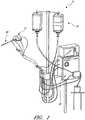
- FIGS 1-3show aspects of a catheter pump 10 that can provide high performance flow rates.
- the pump 10includes a motor driven by a controller 22.
- the controller 22directs the operation of the motor 14 and an infusion system 26 that supplies a flow of infusate in the pump 10.
- a catheter system 80 that can be coupled with the motor 14houses an impeller within a distal portion thereof.
- the impelleris rotated remotely by the motor 14 when the pump 10 is operating.
- the motor 14can be disposed outside the patient.
- the motor 14is separate from the controller 22, e.g., to be placed closer to the patient.
- the motor 14is part of the controller 22.
- the motoris miniaturized to be insertable into the patient.
- Such embodimentsallow the drive shaft to be much shorter, e.g., shorter than the distance from the aortic valve to the aortic arch (about 5 cm or less).
- miniaturized motors catheter pumps and related components and methodsare discussed in US 5,964,694 ; US6,007,478 ; US6,178,922 ; and US 6,176,848 , all of which are hereby incorporated by reference herein in their entirety for all purposes.
- Various embodiments of a motorare disclosed herein, including embodiments having separate drive and driven assemblies to enable the use of a guidewire guide passing through the catheter pump.
- a guidewire guidecan facilitate passing a guidewire through the catheter pump for percutaneous delivery of the pump's operative device to a patient's heart.
- FIG. 3illustrates one use of the catheter pump 10.
- a distal portion of the pump 10, which can include an impeller assembly 92,is placed in the left ventricle LV of the heart to pump blood from the LV into the aorta.
- the pump 10can be used in this way to treat patients with a wide range of conditions, including cardiogenic shock, myocardial infarction, and other cardiac conditions, and also to support a patient during a procedure such as percutaneous coronary intervention.
- One convenient manner of placement of the distal portion of the pump 10 in the heartis by percutaneous access and delivery using the Seldinger technique or other methods familiar to cardiologists.
- Various guide featuresare disclosed herein which enable the pump 10 to be advanced over a guidewire to the heart.
- Example modificationsthat could be used for right side support include providing delivery features and/or shaping a distal portion that is to be placed through at least one heart valve from the venous side, such as is discussed in US 6,544,216 ; US 7,070,555 ; and US 2012-0203056A1 , all of which are hereby incorporated by reference herein in their entirety for all purposes.
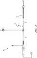
- Figure 2shows features that facilitate small blood vessel percutaneous delivery and high performance, including up to and in some cases exceeding normal cardiac output in all phases of the cardiac cycle.
- the catheter system 80includes a catheter body 84 and a sheath assembly 88.
- the impeller assembly 92is coupled with the distal end of the catheter body 84.
- the impeller assembly 92is expandable and collapsible. In the collapsed state, the distal end of the catheter system 80 can be advanced to the heart, for example, through an artery. In the expanded state the impeller assembly 92 is able to pump blood at high flow rates.
- Figures 2 and 3illustrate the expanded state.
- the collapsed statecan be provided by advancing a distal end 94 of an elongate body 96 distally over the impeller assembly 92 to cause the impeller assembly 92 to collapse.
- Thisprovides an outer profile throughout the catheter assembly 80 that is of small diameter, for example, to a catheter size of about 12.5 FR in various arrangements.
- the impeller assembly 92includes a self-expanding material that facilitates expansion.
- the catheter body 84on the other hand preferably is a polymeric body that has high flexibility. When the impeller assembly 92 is collapsed, as discussed above, high forces are applied to the impeller assembly 92. These forces are concentrated at a connection zone, where the impeller assembly 92 and the catheter body 84 are coupled together. These high forces, if not carefully managed can result in damage to the catheter assembly 80 and in some cases render the impeller within the impeller assembly 92 inoperable. Robust mechanical interface, are provided to assure high performance.
- the mechanical components rotatably supporting the impeller within the impeller assembly 92permit high rotational speeds while controlling heat and particle generation that can come with high speeds.
- the infusion system 26delivers a cooling and lubricating solution to the distal portion of the catheter system 80 for these purposes.
- the space for delivery of this fluidis extremely limited. Some of the space is also used for return of the infusate. Providing secure connection and reliable routing of infusate into and out of the catheter assembly 80 is critical and challenging in view of the small profile of the catheter body 84.
- the catheter pump systemWhen activated, the catheter pump system can effectively increase the flow of blood out of the heart and through the patient's vascular system.
- the pumpcan be configured to produce a maximum flow rate (e.g. low mm Hg) of greater than 4 Lpm, greater than 4.5 Lpm, greater than 5 Lpm, greater than 5.5 Lpm, greater than 6 Lpm, greater than 6.5 Lpm, greater than 7 Lpm, greater than 7.5 Lpm, greater than 8 Lpm, greater than 9 Lpm, or greater than 10 Lpm.
- a maximum flow ratee.g. low mm Hg
- the pumpcan be configured to produce an average flow rate at 62 mmHg of greater than 2 Lpm, greater than 2.5 Lpm, greater than 3 Lpm, greater than 3.5 Lpm, greater than 4 Lpm, greater than 4.25 Lpm, greater than 4.5 Lpm, greater than 5 Lpm, greater than 5.5 Lpm, or greater than 6 Lpm.
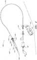
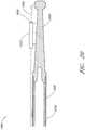
- FIG. 4Another example of a catheter assembly 100A is illustrated in Figure 4 .
- Embodiments of the catheter pump of this applicationcan be configured with a motor that is capable of coupling to (and in some arrangements optionally decoupling from) the catheter assembly 100A.
- This arrangementprovides a number of advantages over a non-disconnectable housing. For example, access can be provided to a proximal end of the catheter assembly 100A prior to or during use.
- a catheter pumpis delivered over a guidewire.
- the guidewiremay be conveniently extended through the entire length of the catheter assembly 100A and out of a proximal portion thereof that is completely enclosed in a coupled configuration.
- connection of the proximal portion of the catheter assembly 100A to a motor housingcan be completed after a guidewire has been used to guide the operative device of the catheter pump to a desired location within the patient, e.g., to a chamber of the patient's heart.
- the connection between the motor housing and the catheter assemblyis configured to be permanent, such that the catheter assembly, the motor housing and the motor are disposable components.
- the coupling between the motor housing and the catheter assemblyis disengageable, such that the motor and motor housing can be decoupled from the catheter assembly after use.
- the catheter assembly distal of the motorcan be disposable, and the motor and motor housing can be re-usable.
- a guidewirecan be inserted through other types of guide features to guide the pump to the heart.
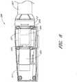
- a priming apparatus 1400can be disposed over an impeller assembly 116A.
- the impeller assembly 116Acan include an expandable cannula or housing and an impeller with one or more blades. As the impeller rotates, blood can be pumped proximally (or distally in some implementations) to function as a cardiac assist device.
- Figure 4also shows one example of a priming apparatus 1400 disposed over the impeller assembly 116A near the distal end 170A of the elongate body 174A.
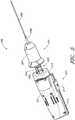
- Figure 4Ais an enlarged view of the priming apparatus 1400 shown in Figure 4 .
- the priming apparatus 1400can be used in connection with a procedure to expel air from the impeller assembly 116A, e.g., any air that is trapped within the housing or that remains within the elongate body 174A near the distal end 170A.
- the priming proceduremay be performed before the pump is inserted into the patient's vascular system, so that air bubbles are not allowed to enter and/or injure the patient.
- the priming apparatus 1400can include a primer housing 1401 configured to be disposed around both the elongate body 174A and the impeller assembly 116A.
- a sealing cap 1406can be applied to the proximal end 1402 of the primer housing 1401 to substantially seal the priming apparatus 1400 for priming, i.e., so that air does not proximally enter the elongate body 174A and also so that priming fluid does not flow out of the proximal end of the housing 1401.
- the sealing cap 1406can couple to the primer housing 1401 in any way known to a skilled artisan.
- the sealing cap 1406is threaded onto the primer housing by way of a threaded connector 1405 located at the proximal end 1402 of the primer housing 1401.
- the sealing cap 1406can include a sealing recess disposed at the distal end of the sealing cap 1406.
- the sealing recesscan be configured to allow the elongate body 174A to pass through the sealing cap 1406.
- the priming operationcan proceed by introducing fluid into the sealed priming apparatus 1400 to expel air from the impeller assembly 116A and the elongate body 174A.
- Fluidcan be introduced into the priming apparatus 1400 in a variety of ways.
- fluidcan be introduced distally through the elongate body 174A into the priming apparatus 1400.
- an inletsuch as a luer, can optionally be formed on a side of the primer housing 1401 to allow for introduction of fluid into the priming apparatus 1400.
- a gas permeable membranecan be disposed on a distal end 1404 of the primer housing 1401.
- the gas permeable membranecan permit air to escape from the primer housing 1401 during priming.
- the priming apparatus 1400also can advantageously be configured to collapse an expandable portion of the catheter assembly 100A.
- the primer housing 1401can include a funnel 1415 where the inner diameter of the housing decreases from distal to proximal.
- the funnelmay be gently curved such that relative proximal movement of the impeller housing causes the impeller housing to be collapsed by the funnel 1415.
- the distal end 170A of the elongate body 174Acan be moved distally relative to the collapsed housing.
- the catheter assembly 100Acan be removed from the priming housing 1400 before a percutaneous heart procedure is performed, e.g., before the pump is activated to pump blood.
- the embodiments disclosed hereinmay be implemented such that the total time for infusing the system is minimized or reduced.
- the time to fully infuse the systemcan be about six minutes or less.
- the time to infusecan be about three minutes or less.
- the total time to infuse the systemcan be about 45 seconds or less. It should be appreciated that lower times to infuse can be advantageous for use with cardiovascular patients.
- the elongate body 174Aextends proximally from the impeller assembly 116A to an infusate device 195 configured to allow for infusate to enter the catheter assembly 100A and for waste fluid to leave the catheter assembly 100A.
- a catheter body 120A(which also passes through the elongate body 174A) can extend proximally and couple to a driven assembly 201.
- the driven assembly 201can be configured to receive torque applied by a drive assembly 203, which is shown as being decoupled from the driven assembly 201 and the catheter assembly 100A in Figure 4 .
- a drive shaftcan extend from the driven assembly 201 through the catheter body 120A to couple to an impeller shaft at or proximal to the impeller assembly 116A.
- the catheter body 120Acan pass within the elongate catheter body 174A such that the external catheter body 174A can axially translate relative to the catheter body 120A.
- Figure 4illustrates a guidewire 235 extending from a proximal guidewire opening 237 in the driven assembly 201.
- a clinicianmay insert the guidewire 235 through the patient's vascular system to the heart to prepare a path for the operative device (e.g. , the impeller assembly 116A) to the heart.
- the catheter assemblycan include a guidewire guide tube (see Figure 12 ) passing through a central internal lumen of the catheter assembly 100A from the proximal guidewire opening 237.
- the guidewire guide tubecan be pre-installed in the catheter assembly 100A to provide the clinician with a preformed pathway along which to insert the guidewire 235.
- the guidewire 235can be advanced through a central lumen extending through the length of the catheter assembly 100A.
- Other embodimentsmay include different types of guide features, as explained herein.
- a guidewireis first placed in a conventional way, e.g., through a needle into a peripheral blood vessel, and along the path between that blood vessel and the heart and into a heart chamber, e.g., into the left ventricle. Thereafter, a distal end opening of the catheter assembly or guidewire guide can be advanced over the proximal end of the guidewire 235 to enable delivery to the catheter assembly 100A. After the proximal end of the guidewire 235 is urged proximally within the catheter assembly 100A and emerges from the guidewire opening 237 and/or guidewire guide, the catheter assembly 100A can be advanced into the patient. In one method, the guidewire guide is withdrawn proximally while holding the catheter assembly 100A. The guidewire guide is taken off of the catheter assembly 100A so that guidewire lumens from the proximal end to the distal end of the catheter assembly 100A are directly over the guidewire.
- the cliniciancan thus insert the guidewire 235 through the proximal guidewire opening 237 and urge the guidewire 235 along the guidewire guide tube until the guidewire 235 extends from a distal guidewire opening (not shown) in the distal end of the catheter assembly 100A.
- the cliniciancan continue urging the guidewire 235 through the patient's vascular system until the distal end of the guidewire 235 is positioned in the desired chamber of the patient's heart.
- a proximal end portion of the guide wire 235can extend from the proximal guidewire opening 237.
- the cliniciancan maneuver the impeller assembly 116A over the guidewire 235 until the impeller assembly 116A reaches the distal end of the guidewire 235 in the heart.
- the cliniciancan remove the guidewire 235 and the guidewire guide tube.
- the guidewire guide tubecan also be removed before or after the guidewire 235 is removed in some implementations. Still other arrangements for inserting the guidewire 235 through different types of guide features are explained in more detail below.
- the cliniciancan activate a motor to rotate the impeller and begin operation of the pump.
- a central lumen or tubee.g., a guidewire guide
- a motor or drive assemblyhaving a lumen through which the guidewire 2.35 can pass.
- the drive assembly 203can be securely coupled to the driven assembly 201 such that vibratory, axial, or other external forces do not decouple the drive assembly 203 from the driven assembly 201 during operation.
- the couplingshould preferably allow a motor to operate effectively so that the drive shaft is rotated at the desired speed and with the desired torque.
- FIG. 5illustrates one embodiment of a motor assembly 206 as the driven assembly 201 is being coupled to the drive assembly 203.
- the driven assembly 201can include a flow diverter 205 and a flow diverter housing 207 that houses the flow diverter 205.
- the flow diverter 205can be configured with a plurality of internal cavities, passages, and channels that are configured to route fluid to and from the patient during a medical procedure.
- an infusatecan be directed into the flow diverter from a source of infusate.
- the infusateis a fluid that Hows into the catheter body 120A to provide useful benefits, such as cooling moving parts and keeping blood from entering certain parts of the catheter assembly 100A.
- the infusateis diverted distally by flow channels in the flow diverter 205.
- a driven magnet 204can be disposed within the flow diverter 205 in various embodiments.
- the driven magnet 204can be journaled for rotation in a proximal portion of the flow diverter housing 207.
- the proximal portioncan project proximally of a proximal face of a distal portion of the flow diverter housing 207.
- the driven magnet 204can be disposed outside the flow diverter 205.
- the driven magnet 204can be configured to rotate freely relative to the flow diverter 205 and/or the flow diverter housing 207.
- the catheter body 120Acan extend from a distal end of the flow diverter housing 207. Further, a drive shaft 208 can pass through the catheter body 120A from the proximal end of the flow diverter housing 207 to the distal end 170A of the elongate body 174A.
- the drive shaft 208can be configured to drive the impeller located at the distal end of the catheter assembly 100A. In some embodiments, a distal end of the drive shaft 208 can couple to an impeller shaft, which rotates the impeller.
- the drive assembly 203can include a drive housing or a motor housing 211 having an opening 202 in a cap 212 of the motor housing 211.
- the motor housing 211can also have a sliding member 213, which can be configured to couple to the patient's body by way of, e.g., a connector 291 coupled to an adhesive or bandage on the patient's body. Because the motor and motor housing 211 can have a relatively high mass, it can be important to ensure that the motor housing 211 is stably supported. In one implementation, therefore, the motor housing 211 can be supported by the patient's body by way of the sliding member 213 and the connector 291 shown in Figure 4 .
- the sliding member 213can slide along a track 214 located on a portion of the motor housing 211, such that relative motion between the motor assembly 206 and the patient does not decouple the sliding member 213 from the patient's body.
- the sliding member 213 and connector 291can therefore be configured to provide a structural interface between the motor housing 206 and a platform for supporting the motor housing 211.
- the platform supporting the motor housing 211can be the patient, since the motor housing 211 may be positioned quite close to the insertion point. In other arrangements, however, the platform supporting the motor housing 211 may be an external structure.
- a securement deviceis configured to lock or secure the drive assembly 203 to the driven assembly 201 once the driven assembly 201 is fully inserted into the drive assembly 203.
- the securement devicecan be configured to secure the drive assembly 203 to the driven assembly 201 by inserting the driven assembly 201 into the drive assembly 203 and then rotating the drive assembly 203 with respect to the driven assembly.
- coupling the drive assembly 203 to the driven assembly 201may be irreversible, such that there may be no release mechanism to decouple the drive assembly 203 from the driven assembly 201.
- the catheter assembly 100A (including the driven assembly 201) and the motor housing 211may be disposable components. In other implementations, however, a release mechanism may be provided to remove the drive assembly 203 from the driven assembly 201. The drive assembly 203 can thereby be used multiple times in some embodiments.
- Figure 6illustrates the motor assembly 206 in the assembled state, e.g., after the drive assembly 203 has been secured to the driven assembly 201.
- the drive assembly 203is activated (e.g., a motor is activated to rotate an output shaft)
- the driven assembly 201which is operably coupled to the drive assembly, is also activated.
- the activated driven assemblycan cause the drive shaft 208 to rotate, which in turn causes the impeller to rotate to thereby pump blood through the patient.
- Figures 7-8illustrate the motor assembly 206 with one wall of the motor housing 211 removed so that various internal components in the housing 211 can be better illustrated.
- a motor 220can be positioned within the housing 211 and mounted by way of a motor mount 226.
- the motor 220can operably couple to a drive magnet 221.
- the motor 220can include an output shaft 222 that rotates the drive magnet 221.
- the drive magnet 221can rotate relative to the motor mount 226 and the motor housing 211.
- the drive magnet 221can be free to translate axially between the motor mount and a barrier 224.
- One advantage of the translating capabilityis to enable the drive magnet 221 and the driven magnet 204 to self-align by way of axial translation.
- the barrier 224can be mounted to the motor housing 211 and at least partially within the cap 212 to support at least the drive magnet 221.
- the drive assembly 203can comprise a plurality of motor windings configured to induce rotation of the drive magnet 221.
- motor windingscan operate directly on a driven magnet within the driven assembly 201. For example, the windings can be activated in phases to create an electric field and thereby commutate the driven magnet.
- the drive magnet 221is illustrated in phantom, such that the driven magnet 204 can be seen disposed within the drive magnet 221.
- the poles of the drive magnet 221can be formed on an interior surface of the drive magnet 221, and the poles of the driven magnet 204 can be formed on an exterior surface of the driven magnet 204.
- the poles of the drive magnet 221can magnetically engage with corresponding, opposite poles of the driven magnet 204 to cause the driven magnet 204 to rotate with, or follow, the drive magnet 221.
- the driven magnet 204can be mechanically coupled to the drive shaft 208, rotation of the drive magnet 221 can cause the driven magnet 204 and the drive shaft 208 to rotate at a speed determined in part by the speed of the motor 220. Furthermore, when the driven magnet 204 is inserted into the drive magnet 221, the poles of each magnet can cause the drive magnet 221 and the driven magnet 204 to self-align. The magnetic forces between the drive magnet 221 and the driven magnet 204 can assist in coupling the drive assembly 203 to the driven assembly 201.
- a first securement device 240is illustrated in Figure 9 .
- the first securement devicecan comprise a first projection 240a and a second projection 240b.
- a locking recess 244can be formed in the cap 212 around at least a portion of a perimeter of the opening 202.
- a lip 242can also extend from the perimeter at least partially into the opening 202. As shown, the lip 242 can also extend proximally from the locking recess 244 such that a step is formed between the locking recess 244 and the lip 242.
- a flange 246can be coupled to or formed integrally with the flow diverter housing 207.
- the flange 246can include a plurality of apertures 247a, 247b, 247c, 247d that are configured to permit tubes and cables to pass therethrough to fluidly communicate with lumens within the flow diverter 205.
- three tubes and one electrical cablecan pass through the apertures 247a-d.
- the electrical cablecan be configured to electrically couple to a sensor within the catheter assembly 100A, e.g., a pressure sensor.
- the three tubescan be configured to carry fluid to and from the catheter assembly 100A.
- a first tubecan be configured to carry infusate into the catheter assembly 100A
- a second tubecan be configured to transport fluids to the pressure sensor region
- the third tubecan be configured to transport waste fluid out of the catheter assembly100A.
- the tubes and cable(s)can pass through the apertures 247a-d of the flange 246 and can rest against the motor housing 211.
- the apertures 247a-dcan advantageously prevent the tubes and cable(s) from becoming entangled with one another or with other components of the catheter pump system.
- the first and second projections 240a, 240bcan pass through the opening and engage the locking recess 244.
- the projections 240a, 240b and the locking recess 244can be sized and shaped such that axial translation of the projections 240a, 240b through the opening 202 causes a flange or tab 248 at a distal end of each projection 240a, 240b to extend over the locking recess 244.
- the tabs 248 at the distal end of the projections 240a, 240bare biased to deform radially outward to engage the locking recess 244 to secure the driven assembly 201 to the drive assembly 203.
- the flow diverter housing 207can be rotated relative to the motor cap 212.
- the clinicianis able to position the impeller assembly 116A within the patient at a desired angle or configuration to achieve the best pumping performance.
- the lip 242can act to restrict the relative rotation between the driven assembly 201 ( e.g., the flow diverter housing 207) and the drive assembly 203 ( e.g. the cap 212 and the motor housing 211).
- the flange 246 and apertures 247a--dcan be circumferentially aligned with the projections 240a, 240b.
- the lip 242can be circumferentially aligned with the sliding member 213, the track 214, and the connector 291 of the motor housing 211. If the flange 246 and projections 240a, 240b are rotated such that they circumferentially align with the lip 242, then the tubes and cable(s) that extend from the apertures 247a-d may become entangled with or otherwise obstructed by the sliding member 213 and the connector 291. Thus, it can be advantageous to ensure that the sliding member 213 and the connector 291 (or any other components on the outer surface of the housing 211) do not interfere or obstruct the tubes and cable(s) extending out of the apertures 247a-d of the flange 246.
- the lip 242 formed in the cap 212can act to solve this problem by ensuring that the flange 246 is circumferentially offset from the sliding member 213 and the connector 291.
- the flow diverter housing 207can be rotated until one of the projections 240a, 240b bears against a side of the lip 242.
- the lip 242can ensure that the flange 246 and apertures 247a-d are circumferentially offset from the sliding member 213, the track 214, and the connector 291.
- connection between the driven assembly 201 and the drive assembly 203may be configured such that the drive assembly 203 may not be removed from the driven assembly 201.
- the secure connection between the two assembliescan advantageously ensure that the motor housing 211 is not accidentally disengaged from the catheter assembly 100A during a medical procedure.
- both the catheter assembly 100A and the drive assembly 203may preferably be disposable.
- the drive assembly 203may be removably engaged with the catheter assembly 100A (e.g., engaged with the driven assembly 201).
- the lip 242may be sized and shaped such that when the drive assembly 203 is rotated relative to the driven assembly 201, the tabs 248 are deflected radially inward over the lip 242 such that the driven assembly 201 can be withdrawn from the opening 202.
- the lip 242may include a ramped portion along the sides of the lip 242 to urge the projections 240a, 240b radially inward. It should be appreciated that other release mechanisms are possible.
- a locking O-ring 253can be mounted to the barrier 224 that is disposed within the motor housing 211 and at least partially within the cap 212.
- the locking O-ring 253can be mounted on an inner surface of the drive or motor housing 203 surrounding the recess or opening 202 into which the driven assembly 212 can be received.
- the locking O-ringcan act as a detent mechanism and can be configured to be secured within an arcuate channel formed in an outer surface of the driven assembly 201, e.g., in an outer surface of the flow diverter 205 in some embodiments.
- various other mechanismscan act as a detent to secure the driven assembly 201 to the drive assembly 203.
- a spring plunger or other type of spring-loaded featuremay be cut or molded into the barrier 224, in a manner similar to the locking O-ring 253 of Figures 10A-10C .
- the spring plunger or spring-loaded featurecan be configured to engage the arcuate channel, as explained below with respect to Figure 10C .
- Skilled artisanswill understand that other types of detent mechanisms can be employed.
- FIG 10Billustrates the same 3D perspective of the drive assembly 203 as shown in Figure 10A , except the cap 212 has been hidden to better illustrate the locking O-ring 253 and a second, stabilizing O-ring 255.
- the O-ring 255is an example of a damper that can be provided between the motor 220 and the catheter assembly 100A.
- the dampercan provide a vibration absorbing benefit in some embodiments. In other embodiment, the damper may reduce noise when the pump is operating.
- the dampercan also both absorb vibration and reduce noise in some embodiments.
- the stabilizing O-ring 255can be disposed within the cap 212 and can be sized and shaped to fit along the inner recess forming the inner perimeter of the cap 212.
- the stabilizing O-ring 255can be configured to stabilize the cap 212 and the motor housing 211 against vibrations induced by operation of the motor 220. For example, as the motor housing 211 and/or cap 212 vibrate, the stabilizing O-ring 255 can absorb the vibrations transmitted through the cap 212. The stabilizing O-ring 255 can support the cap 212 to prevent the cap from deforming or deflecting in response to vibrations. In some implementations, the O-ring 255 can act to dampen the vibrations, which can be significant given the high rotational speeds involved in the exemplary device.
- a damping materialcan also be applied around the motor 220 to further dampen vibrations.
- the damping materialcan be any suitable damping material, e.g., a visco-elastic or elastic polymer.
- the damping materialmay be applied between the motor mount 226 and the motor 220 in some embodiments.
- the damping materialmay also be applied around the body of the motor 220 between the motor 220 and the motor housing 211.
- the damping materialmay be captured by a rib formed in the motor housing 211. The rib may be formed around the motor 220 in some embodiments.
- the flow diverter 205(or the flow diverter housing in some embodiments) can include an arcuate channel 263 formed in an outer surface of the flow diverter 205.
- the arcuate channel 263can be sized and shaped to receive the locking O-ring 253 when the flow diverter 205 is inserted into the opening 202 of the drive assembly 203.
- the locking O-ring 253can be urged or slid over an edge of the channel 263 and can be retained in the arcuate channel 263.
- the locking O-ring 253 and the arcuate channel 263can operate to act as a second securement device. Axial forces applied to the motor assembly 206 can thereby be mechanically resisted, as the walls of the arcuate channel 263 bear against the locking O-ring 253 to prevent the locking o-ring 253 from translating relative to the arcuate channel 263.
- other internal locking mechanismse.g. , within the driven assembly 201 and/or the drive assembly 203 can be provided to secure the driven and drive assemblies 201, 203 together.
- the driven magnet 204 and the drive magnet 221may be configured to assist in securing the two assemblies together, in addition to aligning the poles of the magnets. Other internal locking mechanisms may be suitable.
- Figure 10Calso illustrates a resealable member 266 disposed within the proximal end portion of the driven assembly 201, e.g., the proximal end of the catheter assembly 100A as shown in Figure 4 .
- the proximal guidewire opening 237can be formed in the resealable member 266.
- the guidewire 235can be inserted through the proximal guidewire opening 237 and can be maneuvered through the patient's vasculature. After guiding the operative device of the pump to the heart, the guidewire 235 can be removed from the catheter assembly 100A by pulling the guidewire 235 out through the proximal guidewire opening 237.
- the resealable member 266can therefore be formed of an elastic, self-sealing material that is capable of closing and sealing the proximal guidewire opening 237 when the guidewire 235 is removed.
- the resealable membercan be formed of any suitable material, such as an elastomeric material.
- the resealable member 266can be formed of any suitable polymer, e.g., a silicone or polyisoprene polymer. Skilled artisans will understand that other suitable materials may be used.
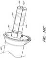
- Figure 11illustrates yet another embodiment of a motor assembly 206A coupled to a catheter assembly.
- a flow diverteris disposed over and coupled to a catheter body 271 that can include a multi-lumen sheath configured to transport fluids into and away from the catheter assembly.
- the flow diverter 205Acan provide support to the catheter body 271 and a drive shaft configured to drive the impeller assembly.
- the motor assembly 206Acan include a motor 220A that has a hollow lumen therethrough.
- the guidewire 235may extend through the proximal guidewire opening 237A formed proximal to the motor 220A, rather than between the motor 220A and the flow diverter 205A.
- a resealable member 266Amay be formed in the proximal guidewire opening 237A such that the resealable member 266A can close the opening 237A when the guidewire 235 is removed from the catheter assembly.
- a rotary seal 273may be disposed inside a lip of the flow diverter 205A. The rotary seal 273 may be disposed over and may contact a motor shaft extending from the motor 220A. The rotary seal 273 can act to seal fluid within the flow diverter 205A. In some embodiments, a hydrodynamic seal can be created to prevent fluid from breaching the rotary seal 273.
- the motor 220Acan be permanently secured to the flow diverter 205A and catheter assembly. Because the proximal guidewire opening 237 is positioned proximal the motor, the motor 220A need not be coupled with the catheter assembly in a separate coupling step. The motor 220A and the catheter assembly can thus be disposable in this embodiment.
- the motor 220Acan include an output shaft and rotor magnetically coupled with a rotatable magnet in the flow diverter 205A.
- the motor 220Acan also include a plurality of windings that are energized to directly drive the rotatable magnet in the flow diverter 205A.
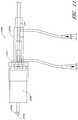
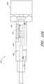
- Figures 12A-12Billustrate another embodiment of a motor coupling having a driven assembly 401 and a drive assembly 403.
- the embodiment of Figures 12A-12Bcan include a mechanical coupling disposed between an output shaft of a motor and a proximal end of a flexible drive shaft or cable.
- the embodiment of Figures 12A-12Bcan include a guidewire guide tube that terminates at a location distal to a motor shaft 476 that extends from a motor 420.
- an adapter shaft 472can operably couple to the motor shaft 476 extending from the motor 420.
- a distal end portion 477 of the adapter shaft 472can mechanically couple to a proximal portion of an extension shaft 471 having a central lumen 478 therethrough.
- one or more trajectories 473can be formed in channels within a motor housing 475 at an angle to the central lumen 478 of the extension shaft 471.
- the motor housing 475can enclose at least the adapter shaft 472 and can include one or more slots 474 formed through a wall of the housing 475.
- a guidewire(not shown in Figure 12B ) may pass through the guidewire guide tube from the distal end portion of the catheter assembly and may exit the assembly through the central lumen 478 near the distal end portion 477 of the adapter shaft 472 (or, alternatively, near the proximal end portion of the extension shaft 471).
- one of the extension shaft 471 and the adapter shaft 472may include a resealable member disposed therein to reseal the lumen through which the guidewire passes, as explained above.
- the extension shaft 471 and the adapter shaft 472can be combined into a single structure.
- the guidewireWhen the guidewire exits the central lumen 478, the guidewire can pass along the angled trajectories 473 which can be formed in channels and can further pass through the slots 474 to the outside environs.
- the trajectories 473can follow from angled ports in the adapter shaft 472.
- a cliniciancan thereby pull the guidewire through the slots 474 such that the end of the guidewire can easily be pulled from the patient after guiding the catheter assembly to the heart chamber or other desired location.
- the motor shaft 476 and motor 420need not include a central lumen for housing the guidewire. Rather, the motor shaft 476 may be solid and the guidewire can simply pass through the slots 474 formed in the side of the housing 475.
- the drive assembly 403can mechanically couple to the driven assembly 401.
- a distal end portion 479 of the extension shaft 471may be inserted into an opening in a flow diverter housing 455.
- the distal end portion 479 of the extension shaft 471may be positioned within a recess 451 and may couple to a proximal end of a drive cable 450 that is mechanically coupled to the impeller assembly.
- a rotary seal 461may be positioned around the opening and can be configured to seal the motor 420 and/or motor housing 475 from fluid within the flow diverter 405.
- the embodiments of Figures 12A-Ballow the motor 420 to be positioned proximal of the rotary seal in order to minimize or prevent exposing the motor 420 to fluid that may inadvertently leak from the flow diverter.
- the extension shaft 471may be lengthened in order to further isolate or separate the motor 420 from the fluid diverter 405 in order to minimize the risk of leaking fluids.
- Figure 13illustrates a distal end portion 300 of a catheter assembly, such as the catheter assembly 100A described above.
- a cannula housing 302can couple to a distal tip member 304.
- the distal tip member 304can be configured to assist in guiding the operative device of the catheter assembly, e.g., an impeller assembly (which can be similar to or the same as impeller assembly 116A), along the guidewire 235.
- the exemplary distal tip member 304is formed of a flexible material and has a rounded end to prevent injury to the surrounding tissue.
- the distal tip member 304contacts a portion of the patient's anatomy (such as a heart wall or an arterial wall), the distal tip member 304 will safely deform or bend without harming the patient.
- the tipcan also serve to space the operative device away from the tissue wall.
- a guide feature or guidewire guide tube 312can be provided.
- the guidewire guide tube 312, discussed above with reference to Figure 4can extend through a central lumen of the catheter assembly.
- the guidewire guide tube 312can pass through the impeller shaft (not shown, as the impeller is located proximal to the distal end portion 300 shown in Figure 13 ) and a lumen formed within the distal tip member 304.
- the guidewire guide tube 312 of Figure 13can comprise a central lumen extending throughout the length of the catheter assembly 100A.
- the guidewire guide tube 312may extend distally past the distal end of the distal tip member 304.
- the cliniciancan introduce a proximal end of the the guidewire into the distal end of the guidewire guide tube 312, which in Figure 13 extends distally beyond the tip member 304.
- the distal tip member 304can comprise a flexible, central body 306, a proximal coupling member 308, and a rounded tip 310 at the distal end of the tip member 304.
- the central body 306can provide structural support for the distal tip member 304.
- the proximal coupling member 308can be coupled to or integrally formed with the central body 306.
- the proximal coupling member 308can be configured to couple the distal end of the cannula housing 302 to the distal tip member 304.
- the rounded tip 310also referred to as a ball tip, can be integrally formed with the central body 306 at a distal end of the tip member 304.
- the rounded tip 310is flexible and has a round shape, if the tip member 304 contacts or interacts with the patient's anatomy, the rounded tip 310 can have sufficient compliance so as to deflect away from the anatomy instead of puncturing or otherwise injuring the anatomy.
- the distal tip member 304can advantageously include sufficient structure by way of the central body 306 such that the tip member 304 can accurately track the guidewire 235 to position the impeller assembly within the heart. Yet, because the tip member 304 is made of a flexible material and includes the rounded tip 310, any mechanical interactions with the anatomy can be clinically safe for the patient.
- One potential problem with the embodiment of Figure 13is that it can be difficult for the clinician to insert the guidewire into the narrow lumen of the guidewire guide tube 312. Since the guidewire guide tube 312 has a small inner diameter relative to the size of the clinician's hands, the clinician may have trouble inserting the guidewire into the distal end of the guidewire guide tube 312, which extends past the distal end of the tip member 304 in Figure 13 . In addition, when the clinician inserts the guidewire into the guidewire guide tube 312, the distal edges of the guidewire guide tube 312 may scratch or partially remove a protective coating applied on the exterior surface of the guidewire. Damage to the coating on the guidewire may harm the patient as the partially uncoated guidewire is passed through the patient's vasculature. Accordingly, it can be desirable in various arrangements to make it easier for the clinician to insert the guidewire into the distal end of the catheter assembly, and/or to permit insertion of the guidewire into the catheter assembly while maintaining the protective coating on the guidewire.
- the cannula housing 302(which may form part of an operative device) may be collapsed into a stored configuration in some embodiments such that the cannula housing is disposed within an outer sheath.
- a distal end or edge of the outer sheathmay abut the tip member 304.
- the distal edge of the outer sheathmay extend over the tip member 304A, or the sheath may have an outer diameter such that the distal edge of the outer sheath is exposed.
- the distal edge of the outer sheathmay scratch, scrape, or otherwise harm the anatomy. There is a therefore a need to prevent harm to the patient's anatomy due to scraping of the distal edge of the sheath against the vasculature.
- Figure 14is a side cross-sectional view of a distal tip member 304A disposed at a distal end 300A of the catheter assembly, according to another embodiment.
- the reference numerals in Figure 14may refer to components similar to or the same as those in Figure 13 .
- the distal tip member 304Acan couple to a cannula housing 302A.
- the distal tip member 304Acan include a flexible, central body 306A, a proximal coupling member 308A, and a rounded tip 310A at the distal end of the tip member 304A.
- a guide feature or guidewire guide tube 312Acan pass through the cannula housing 302A and a lumen passing through the distal tip member 304A.
- the central body 306Acan include a bump 314 disposed near a proximal portion of the tip member 304A.
- the bump 314 illustrated in Figure 14may advantageously prevent the outer sheath from scraping or scratching the anatomy when the sheath is advanced through the patient's vascular system.
- the sheathwill advance over the cannula housing 302A such that the distal edge or end of the sheath will abut or be adjacent the bump 314 of the tip member 304A.
- the bump 314can act to shield the patient's anatomy from sharp edges of the outer sheath as the distal end 300A is advanced through the patient.
- the patientmay not be harmed when the bump 314 interact with the anatomy, because the bump 314 includes a rounded, smooth profile. Accordingly, the bump 314 in Figure 14 may advantageously improve patient outcomes by further protecting the patient's anatomy.
- the guidewire guide tube 312A of Figure 14does not extend distally past the end of the tip member 306A. Rather, in Figure 14 , the central lumen passing through the tip member 304A may include a proximal lumen 315 and a distal lumen 313. As shown in Figure 14 , the proximal lumen 315 may have an inner diameter larger than an inner diameter of the distal lumen 313. A stepped portion or shoulder 311 may define the transition between the proximal lumen 315 and the distal lumen 313. As illustrated in Figure 14 , the inner diameter of the proximal lumen 315 is sized to accommodate the guidewire guide tube 312A as it passes through a portion of the tip member 304A.
- the inner diameter of the distal lumen 313 in Figure 14is sized to be smaller than the outer diameter of the guidewire guide tube 312A such that the guidewire guide tube 312A is too large to pass through the distal lumen 313 of the tip member 304A.
- the thickness of the guidewire guide tube 312Amay be made smaller than the height of the stepped portion or shoulder 311, e.g., smaller than the difference between the inner diameter of the proximal lumen 315 and the inner diameter of the distal lumen 313.
- the embodiment illustrated in Figure 14may assist the clinician in inserting the guidewire (e.g., the guidewire 235 described above) into the distal end 300A of the catheter assembly.
- the guidewire guide tube 312Amay be inserted through the central lumen of the catheter assembly.
- the guidewire guide tube 312Amay pass distally through a portion of the motor, the catheter body, the impeller assembly and cannula housing 302A, and through the proximal lumen 315 of the tip member 304A.
- the guidewire guide tube 312Amay be urged further distally until the distal end of the guidewire guide tube 312A reaches the shoulder 311.
- the shoulder 311may prevent further insertion of the guidewire guide tube 312 in the distal direction. Because the inner diameter of the distal lumen 313 is smaller than the outer diameter of the guidewire guide tube 312A, the distal end of the guidewire guide tube 312A may be disposed just proximal of the shoulder 311, as shown in Figure 14 .
- the clinicianmay insert the proximal end of the guidewire (such as the guidewire 235 described above) proximally through the distal lumen 313 passing through the rounded tip 310A at the distal end of the tip member 304A. Because the tip member 304A is flexible, the clinician can easily bend or otherwise manipulate the distal end of the tip member 304A to accommodate the small guidewire. Unlike the guidewire guide tube 312A, which may be generally stiffer than the tip member 304A, the clinician may easily deform the tip member 304A to urge the guidewire into the distal lumen 313.
- the cliniciancan urge the guidewire proximally past the stepped portion 311 and into the larger guidewire guide tube 312A, which may be positioned within the proximal lumen 315.
- the exemplary guide tube and shoulderadvantageously avoid damaging or removing the coating.
- the shoulder 311may substantially prevent the guidewire guide tube 312A from scraping the exterior coating off of the guidewire. Instead, the guidewire easily passes from the distal lumen 313 to the proximal lumen 315. The guidewire may then be urged proximally through the impeller and catheter assembly until the guidewire protrudes from the proximal end of the system, such as through the proximal guidewire opening 237 described above with reference to Figure 4 .
- the guidewire guide features(e.g., guidewire guide tubes 312, 312A) illustrated in Figure 13-14 include a central lumen passing through the catheter assembly along its length. In some embodiments, it may be desirable to omit the central lumen through the catheter assembly. For example, removing the central lumen from the drive cable and motor assembly may advantageously simplify the manufacturing process and may reduce the profile ( e.g., diameter) of the catheter assembly. Accordingly, various embodiments disclosed herein include catheter assemblies that comprise a guidewire guide feature configured to receive a guidewire along a side of the catheter assembly. In some embodiments, the guide feature can be configured to receive a guidewire only along the side of the catheter assembly. In other embodiments, the guide feature can be configured to receive a guidewire along a portion of the side of the catheter assembly and through a central lumen that extends along only a portion of the catheter assembly.
- Figure 15is a schematic side cross-sectional view of a distal end portion 500 of a catheter assembly having a guide feature 512 along a side of a cannula housing 502.
- a tip member 504can be coupled with a distal portion of the cannula housing 502.
- the impelleris not illustrated in Figure 15 for ease of illustration, but it should be appreciated that, as in the above-described embodiments, the impeller can be disposed in the cannula housing 502.
- the cannula housing 502can be similar to the cannula housing 302 or 302A described above.
- the impellercan be positioned within the cannula housing 502.
- the impeller and cannula housing 502can have a collapsed state, in which the cannula housing 502 is inserted into the patient's vascular system and guided to the heart.
- the cannula housing 502can be expanded into an expanded or deployed configuration within the heart, and the impeller (not shown in Figure 15 ) can be rotated to pump blood.
- the impellercan be driven by an impeller shaft connected to a motor.
- the motorcan be positioned within the patient's body or outside the patient's body.
- the cannula housing 502 illustrated schematically in Figure 15is shown in the expanded configuration.
- the guide feature 512is disposed on an outer surface or side of the catheter assembly, rather than through a central lumen of the catheter assembly.
- the guide feature 512is coupled to or formed with an outer wall of the cannula housing 502.
- the guide feature 512can comprise a tubular segment having a guide lumen 509 therethrough.
- the tubular segmentcan comprise any suitable cross-section, such as a generally cylindrical cross-section or other suitable profile.
- a guidewire 535can be inserted through the guide lumen 509 of the guide feature 512.
- the guidewire 535can be advanced through the patient's vascular system to a treatment location in the heart (e.g., the left ventricle).
- the catheter assemblycan be advanced over the guidewire 535 until the tip member 504 and cannula housing 502 are disposed at the treatment location.
- the cannula housing 502can straddle the aortic valve, and the distal tip member 504 can be disposed in the left ventricle.
- the guide feature 512can be sufficiently flexible or collapsible such that, when the cannula housing 502 is collapsed ( e.g., by way of an outer sheath), the guide feature 512 can also collapse.
- the guide feature 512can be formed from a flexible material, such as a polymer, which can deform when a sheath is advanced over the feature 512.
- the sheathcan be advanced to bear against the proximal end of the guide feature 512. The clinician can urge the sheath against the proximal end of the guide feature 512 to collapse the housing 502.
- the sheathcan include a slot or recess aligned with the guide feature 512.
- the slot or recesscan be sized and shaped to accommodate the guide feature 512 such that when the sheath is advanced over the cannula housing 502, the guide feature 512 is received in the slot or recess.
- Other suitable ways of collapsing the guide feature 512may be suitable.
- the guide feature 512may not be collapsible, and the outer sheath may have a diameter large enough to accommodate the cannula housing 502 and the guide feature 512 on the outer wall of the housing 502.
- the profile (e.g., diameter) of the catheter assemblycan be reduced.
- Providing a pump with a smaller cross-sectionmay improve the maneuverability of the catheter assembly and may reduce risks associated with hemolysis and other health risks to the patient.
- Figure 16is a schematic side cross-sectional view of a distal end portion 600 of a catheter assembly having a guide feature 612 along a side of an outer sheath 674.
- the catheter assemblycan include a cannula housing 602 and a distal tip member 604 coupled with the cannula housing 602.
- the cannula housing 602is illustrated in the collapsed configuration, e.g., in a stored configuration in which the cannula housing 602 can be percutaneously delivered to the treatment location in the heart.
- the collapsed cannula housing 602can be disposed in the outer sheath 674 prior to and during insertion of the catheter assembly into the patient.
- the cannula housing 602can be held in the collapsed configuration by the outer sheath 674.
- the cannula housing 602can be urged out of the sheath 674 (or the sheath 674 retracted), and the housing 602 and impeller (not shown in Figure 16 ) can expand to the expanded configuration.
- the impellercan be driven by an impeller shaft connected to a motor.
- the motorcan be positioned within the patient's body or outside the patient's body.
- the guide feature 612can be disposed on an outer surface or side of the outer sheath 674, rather than on an outer side of the cannula housing 602.
- a transition channel 616can be formed in the tip member 604.
- the transition channel 616can extend from an outer surface of the tip member 604 to an internal lumen 615 within the tip member 604.
- a proximal end of the transition channel 616can be open to blood flowing past the tip member 604, and a distal end of the transition channel 616 can connect with the internal lumen 615.
- the transition channel 616can enable the use of a rapid exchange guiding system while also allowing the atraumatic tip member 604 to be tracked and controlled during insertion of the catheter assembly.
- the internal lumen 615can extend distally through the distal end of the tip member 604.
- the cliniciancan insert a guidewire 635 through a guide lumen 609 of the guide feature 612, the transition channel 616, and the internal lumen 615 of the tip member 604.
- the cliniciancan insert the guidewire 635 along a proximal direction, such that the clinician advances the guidewire 635 proximally through the distal end of the tip member 604 and into the internal lumen 615, outwardly through the transition channel 616, and through the guide lumen 609 of the guide feature 612.
- the internal lumen 615may terminate at the connecting channel 616 so that the guidewire is automatically guided through the connecting channel 616 to the outside of the tip member 604.
- the cliniciancan insert the guidewire 635 along a distal direction, such that the clinician inserts the guidewire 635 distally through the lumen 609 of the guide feature 612, inwardly through the transition channel 616, and distally through the internal lumen 615 of the tip member 604 until the guidewire 635 emerges from the distal end of the tip member 604.
- the cliniciancan advance the guidewire 635 through the anatomy to the treatment location.
- the distal portion 600 of the catheter assemblycan be urged over the guidewire 635 to position the cannula housing 602 and tip member 604 at the treatment location.
- the embodiment illustrated in Figure 16may not include a central lumen through proximal portions, such as through the drive shaft and motor assembly. Rather, the internal lumen 615 may be provided through a portion of the catheter assembly, e . g. , through at least a portion of the tip member 604. Eliminating the central lumen through the drive shaft and motor assembly may reduce the profile of the catheter assembly and simplify manufacturing techniques. The lumen 615 in the tip member 604 may improve the flexibility of the tip member 604, which may therefore improve the maneuverability of the tip member 604 through the vascular system.
- the guide feature 612may avoid difficulties that may arise when collapsing the cannula housing 502 of Figure 15 . Because the outer sheath 674 is disposed outside the left ventricle during operation of the pump, the guide feature 612 is similarly disposed outside the left ventricle, which may advantageously improve the flow characteristics of blood pumped from the ventricle and may reduce the risk of other complications from disposing the guide feature 612 in the left ventricle during pump operation.
- Figure 17Ais a schematic side cross-sectional view of a distal end portion 700 of a catheter assembly having a guide feature 712 extending radially inward from an outer sheath 774.
- Figure 17Bis a schematic side cross-sectional view illustrating the outer sheath 774, cannula housing 702, and tip member 704 in an unassembled configuration.
- the catheter assemblycan include an outer sheath 774, a cannula housing 702 disposed in the outer sheath 774, and a distal tip member 704 coupled with the cannula housing 702.
- the cannula housing 702is illustrated in the collapsed configuration; in Figure 17B , the cannula housing 702 is illustrated in the expanded configuration.
- the catheter assemblycan include an impeller driven by an impeller shaft connected to a motor.
- the motorcan be positioned within the patient's body or outside the patient's body.
- the outer sheath 774can comprise the guide feature 712, in addition to a tubular wall portion 717 configured to retain the cannula housing 702 and impeller (not shown in Figures 17A-17B ) in the collapsed or stored configuration.
- the guide feature 712can comprise a transition channel 716 extending radially inwardly from the wall portion 717, and an inner portion 714 extending longitudinally within the wall portion 717 (and which may be centered relative to the wall portion 717).
- a guide lumen 709 of the guide feature 712can extend through the transition channel 716 and the inner portion 714.
- the transition channel 716can be inserted through an aperture 718 in the cannula 702.
- the aperture 718can be functionally distinct from one or more outlets on the housing 702. In other arrangements, the transition channel 716 can be inserted through other apertures or windows that form one or more outlets in the catheter assembly.
- the cliniciancan insert a guidewire 735 distally through the transition channel 716 of the sheath 774 and can advance the guidewire 735 through the inner portion 714.
- a distal end of the inner portion 714can be disposed at or near the proximal end of the tip member 706 such that the guide lumen 709 communicates with an internal lumen 715 of the tip member 706.
- the guidewire 735can be advanced from the inner portion 714 through the internal lumen 715 and out the distal end of the tip member 704.
- the guidewire 735can be advanced proximally such that the guidewire 735 passes proximally through the internal lumen 715, through the inner portion 714, and out through the transition channel 716.
- the cliniciancan advance the guidewire 735 through the patient's vascular system to the treatment location (e.g., the left ventricle of the heart).
- the cliniciancan urge the catheter assembly over the guidewire 735 to position the tip member 704 and cannula housing 702 at the treatment location.
- the cannula housing 702 and impellercan be urged from the sheath 774 (or the sheath 774 retracted from the housing 702), and the impeller can be activated to conduct a treatment procedure.
- the cliniciancan advance the sheath 774 over the cannula housing 702 and can align the inner portion 714 of the sheath 774 such that the inner portion 714 is inserted into the aperture 718 of the cannula housing 702.
- the sheath 774can collapse the housing 702, and the catheter assembly can be withdrawn from the patient.
- the inner portion 714need not be re-inserted into the aperture 718 because removing the distal end portion 700 from the patient can be done without the use of a guide wire.
- the inner portion 714 and transition channel 716may be disposed anywhere inside the sheath 774, e.g., collapsed against an inner wall of the sheath 774 before or while collapsing the cannula housing 702.
- the inner portion 714 and transition channel 716can be removed prior to collapsing the cannula housing 702.
- the embodiment shown in Figures 17A-17Bcan reduce the profile of the catheter assembly by enabling the use of a drive shaft and motor assembly that do not include an inner lumen. Furthermore, as compared with the embodiments of Figures 15 and 16 , the embodiment of Figures 17A-17B do not include a guide feature projecting outward from an outer surface of the assembly, which may enable a decrease in the diameter of the catheter assembly and/or may decrease the difficulty of collapsing the cannula housing in the sheath.
- Figure 18is a schematic side cross-sectional view of a distal end portion 800 of a catheter assembly having a guide feature 812 along a side of an outer sheath 874.
- Figure 18is similar to the embodiment shown in Figure 16 , except that a guidewire 835 is advanced only along an outer surface or side of the catheter assembly instead of through a lumen in a tip member 804.
- a cannula housing 802(shown in the collapsed configuration) can be retained within a sheath 874, and the tip member 804 can be coupled to a distal portion of the cannula housing 802.
- an impeller(not shown) can be driven by an impeller shaft connected to a motor.
- the motorcan be positioned within the patient's body or outside the patient's body.
- a guide feature 812(which may comprise a short tubular segment) can be coupled to an outer surface of the sheath 874.
- the tip member 804does not include a transition channel through which a guidewire is passed.
- the tip member 804may not include an inner lumen.
- the cliniciancan insert the guidewire 835 through a guide lumen 809 of the guide feature 812 and can pass the guidewire 835 along the outside of the tip member 804.
- the cliniciancan advance the guidewire 835 through the patient's vasculature to the treatment location.
- the catheter assemblycan be urged along the guidewire 835 to the treatment location.
- the embodiment of Figure 18can reduce the profile of the catheter assembly.
- the embodiment of Figure 18may prevent blood from collecting in the tip member 804.
- Figure 19is a schematic side cross-sectional view of a distal end portion 900 of a catheter assembly having a guide feature 912 extending through a tip member 904.
- the embodiment shown in Figure 19is similar to the embodiment of Figure 16 , except the guide feature 912 is disposed entirely within the tip member 904, instead of including a portion along the outside of an outer sheath 974.
- a cannula housing 902can be retained within the sheath 974.
- an impeller(not shown) can be driven by an impeller shaft connected to a motor. The motor can be positioned within the patient's body or outside the patient's body.
- the embodiment of Figure 19does not include a tubular segment on the outside of the sheath 974. Rather, the guide feature 912 includes a transition channel 916 and internal lumen 915 formed through the tip member 904. The clinician can insert a guidewire 935 through the transition channel 916 and can advance the guidewire through the internal lumen 915. The guidewire 935 can be inserted into the patient's anatomy, and the catheter assembly can be urged over the guidewire 935 to the treatment location.
- the embodiment of Figure 19can advantageously be used without guide features on the outside of the catheter assembly (such as the guide feature 612 of Figure 16 ).
- the tip member 904can include internal lumen 915 and channel 916, there may be no inner lumen formed in the drive shaft or motor assembly, which can reduce the profile of the catheter assembly. Furthermore, in some embodiments, the internal lumen 915 can terminate at or near the transition channel 916 such that the guidewire is automatically directed or guided through the transition channel 916 and outside the tip member 904.
- Figure 20is a schematic side cross-sectional view of a distal end portion 1000 of a catheter assembly having a guide feature 1012 (not shown in cross-section) disposed on an outer surface of a tip member 1004.
- the distal end portion 1000can include an outer sheath 1074 and a cannula housing 1002 retained within the sheath 1074.
- the tip member 1004can be coupled with the cannula housing 1002.
- a guide feature 1012e.g., a short tubular segment
- the guide feature 1012can include a guide lumen 1009 through which a guidewire 1035 can be inserted.
- the cliniciancan advance the guidewire 1035 through the vascular system of the patient, and can urge the distal end portion 1000 of the catheter assembly over the guidewire 1035 to the treatment location.
- the embodiment of Figure 20can reduce the profile of the catheter assembly be omitting an internal lumen within the catheter assembly. Furthermore, by disposing the guide feature 1012 on the tip member 1004, rather than on the cannula housing 1002, the sheathing and collapse of the cannula housing 1002 may not be affected by the guide feature 1 0 12.
- the guide feature 1012 in Figure 20is illustrated at an intermediate portion of the tip member 1004. In other embodiments, however, the guide feature 1012 may be positioned nearer a proximal portion of the tip member 1004, e.g., near the housing 1002. In other arrangements, the guide feature 1012 may be positioned nearer a distal portion of the tip member 1004, e.g., near the atraumatic ball-like tip.
- the tip member 1004 and guide feature 1012may be configured to have a low profile, which can assist with insertion of the catheter assembly into the patient's body.
- the guide feature 1012can be connected with the tip member 1004 such that the combined width of the guide feature 1012 and tip member 1004 is as small as possible.
- a low profile arrangementmay also be enabled at least in part by not providing a central or internal lumen, such as the lumen 915 shown in Figure 19 .
- an impeller(not shown) can be driven by an impeller shaft connected to a motor.
- the motorcan be positioned within the patient's body or outside the patient's body.
Landscapes
- Health & Medical Sciences (AREA)
- Heart & Thoracic Surgery (AREA)
- Engineering & Computer Science (AREA)
- Life Sciences & Earth Sciences (AREA)
- Cardiology (AREA)
- Hematology (AREA)
- Biomedical Technology (AREA)
- Anesthesiology (AREA)
- Animal Behavior & Ethology (AREA)
- General Health & Medical Sciences (AREA)
- Public Health (AREA)
- Veterinary Medicine (AREA)
- Mechanical Engineering (AREA)
- Vascular Medicine (AREA)
- Pulmonology (AREA)
- Biophysics (AREA)
- External Artificial Organs (AREA)
Abstract
Description
- This application claims priority to
U.S. Provisional Patent Application No. 62/038,678, filed August 18, 2014 - This application is directed to catheter pumps for mechanical circulatory support of a heart.
- Heart disease is a major health problem that has high mortality rate. Physicians increasingly use mechanical circulatory support systems for treating heart failure. The treatment of acute heart failure requires a device that can provide support to the patient quickly. Physicians desire treatment options that can be deployed quickly and minimailly-invasively.
- Intra-aortic balloon pumps (IABP) are currently the most common type of circulatory support devices for treating acute heart failure. IABPs are commonly used to treat heart failure, such as to stabilize a patient after cardiogenic shock, during treatment of acute myocardial infarction (MI) or decompensated heart failure, or to support a patient during high risk percutaneous coronary intervention (PCI). Circulatory support systems may be used alone or with pharmacological treatment.
- In a conventional approach, an IABP is positioned in the aorta and actuated in a counterpulsation fashion to provide partial support to the circulatory system. More recently minimally-invasive rotary blood pump have been developed in an attempt to increase the level of potential support (i.e., higher flow). A rotary blood pump is typically inserted into the body and connected to the cardiovascular system, for example, to the left ventricle and the ascending aorta to assist the pumping function of the heart. Other known applications pumping venous blood from the right ventricle to the pulmonary artery for support of the right side of the heart. An aim of acute circulatory support devices is to reduce the load on the heart muscle for a period of time, to stabilize the patient prior to heart transplant or for continuing support.
- There is a need for improved mechanical circulatory support devices for treating acute heart failure. Fixed cross-section ventricular assist devices designed to provide near full heart flow rate are either too large to be advanced percutaneously (e.g., through the femoral artery without a cutdown) or provide insufficient flow.
- There is a need for a pump with improved performance and clinical outcomes. There is a need for a pump that can provide elevated flow rates with reduced risk of hemolysis and thrombosis. There is a need for a pump that can be inserted minimally-invasively and provide sufficient flow rates for various indications while reducing the risk of major adverse events. In one aspect, there is a need for a heart pump that can be placed minimally-invasively, for example, through a 15FR. or 12FR incision. In one aspect, there is a need for a heart pump that can provide an average flow rate of 4 Lpm or more during operation, for example, at 62 mmHg of head pressure. While the flow rate of a rotary pump can be increased by rotating the impeller faster, higher rotational speeds are known to increase the risk of hemolysis, which can lead to adverse outcomes and in some cases death. Accordingly, in one aspect, there is a need for a pump that can provide sufficient flow at significantly reduced rotational speeds. These and other problems are overcome by the inventions described herein.
- Further, there is a need for a motor configured to drive an operative device,e.g., a impeller, at a distal portion of the pump. It can be important for the motor to be configured to allow for percutaneous insertion of the pump's operative device.
- There is an urgent need for a pumping device that can be inserted percutaneously and also provide full cardiac rate flows of the left, right, or both the left and right sides of the heart when called for.
- In one embodiment, a catheter assembly is disclosed. The catheter assembly can include a cannula disposed at a distal portion of the catheter assembly. The cannula can have a collapsed configuration and an expanded configuration. The cannula can be arranged to permit the flow of blood therethrough when in the expanded configuration. The catheter assembly can comprise a tip member coupled with a distal portion of the cannula. A guide feature can be configured to receive a guidewire through a guide lumen formed through the guide feature. The catheter assembly can be configured such that, when the catheter assembly is inserted into a patient with the guidewire, the guidewire passes through the guide lumen and along at least a portion of an outer surface of the catheter assembly.
- In another embodiment, a catheter assembly is disclosed. The catheter assembly can comprise an expandable cannula disposed at a distal portion of the catheter assembly. The expandable cannula can have a collapsed configuration and an expanded configuration. The expandable cannula can be arranged to permit the flow of blood therethrough when in the expanded configuration, The catheter assembly can include a guide feature having a guide lumen extending distally of a proximal end of the guide feature. The proximal end of the guide feature can be located adjacent to or distal of the proximal end of the expandable cannula.
- In one embodiment, a catheter pump is disclosed. The catheter pump can include a catheter assembly. The catheter assembly can include a drive shaft having a proximal end and a distal end. An impeller may be coupled with the distal end of the drive shaft. A driven magnet assembly may be coupled with the proximal end of the drive shaft. The driven magnet assembly can include a driven magnet housing having a driven magnet. The catheter pump can further include a drive system. The drive system can include a motor having an output shaft. The drive system can also include a drive magnet assembly coupled with the output shaft. The drive magnet assembly can include a drive magnet housing with a drive magnet disposed therein. A securement device can be configured to secure the driven magnet housing into engagement with the drive magnet housing during operation of the pump.
- In another embodiment, a catheter pump is disclosed. The catheter pump can include a catheter assembly. The catheter assembly can comprise a drive shaft having a proximal end and a distal end. An impeller can be coupled with the distal end of the drive shaft. A rotatable magnet can be coupled with the proximal end. The rotatable magnet can be disposed in a driven magnet housing. Furthermore, the catheter pump can include a drive system comprising a plurality of motor windings configured to induce rotation of the rotatable magnet when the driven magnet housing is engaged with the drive system. A locking device can be configured to be engaged by insertion of the driven magnet housing into an opening of the drive system.
- In yet another embodiment, a method is disclosed. The method can include inserting a proximal portion of a catheter assembly containing a magnet into a recess of a drive unit. The method can further include engaging a locking device to secure the proximal portion of the catheter assembly to the drive unit.
- In another embodiment, a catheter assembly is disclosed. The catheter assembly can include a catheter body having a proximal portion and a distal portion. An operative device can be coupled to the distal portion of the catheter body. A tip member can be coupled to a distal portion of the operative device. The tip member can have a lumen comprising a first section and a second section connected to the first section. An inner diameter of the first section can be larger than an inner diameter of the second section.
- In one embodiment, a catheter pump is provided that includes a catheter assembly and a drive system, and a securement device. The catheter assembly includes a drive shaft, an impeller, and a driven assembly. The drive shaft has a proximal end and a distal end. The impeller is coupled with the distal end of the drive shaft. The driven assembly may be coupled with the proximal end of the drive shaft, the driven assembly is disposed in a driven housing. The drive system includes a motor having an output shaft and a drive assembly coupled with the output shaft. The drive assembly includes a drive housing with at least one magnet disposed therein. The securement device is configured to prevent disengagement of the driven housing from the drive housing during operation of the pump.
- In one embodiment, a catheter pump is provided that includes a catheter assembly and a drive system, and a damper. The catheter assembly includes a drive shaft, an impeller, and a driven member. The drive shaft has a proximal end and a distal end. The impeller is coupled with the distal end of the drive shaft. The driven member is coupled with the proximal end of the drive shaft. The drive system includes a motor having an output shaft and a drive member coupled with the output shaft.
- In one variant, the catheter pump can have a damper disposed between the drive and driven member. The damper can be configured to isolate the drive member or the motor from vibration in the catheter assembly. The damper can be configured to suppress noise at or around the connection between the drive and drive members.
- Preferably, the damper is disposed radially around the output shaft, e.g., completely surrounding the output shaft. The damper can be disposed between separable housings of the catheter assembly and drive system, e.g., abutting a distal face of a drive system housing and a proximal face of a driven member housing disposed on the proximal end of the catheter assembly.
- This embodiment can be augmented in some embodiments with a disconnectable coupling between the drive and driven members. For example, a securement device can be configured to permit selective disengagement of these components from each other. The securement device can be configured to prevent disengagement of the driven housing from the drive housing during operation of the pump.
- Connection of the drive and driven members can be by the mutual attraction of opposing poles of permanent magnets disposed therein. Alternatively, the driven member can be positioned to be acted upon magnetic fields generated in the winding, e.g., using commutation in the windings. In another embodiment, the drive and driven members are coupled using direct mechanical drive, such as with gears, splines or other abutting surfaces.
- In another embodiment, a catheter pump is provided that has a catheter assembly, a drive system, and a locking device. The catheter assembly has a drive shaft that has a proximal end and a distal end. An impeller is coupled with the distal end of the drive shaft. A rotatable magnet is coupled with the proximal end of the drive shaft. The rotatable magnet is disposed in a driven magnet housing. The drive system has a plurality of motor windings configured to induce rotation of the rotatable magnet after the driven magnet housing is engaged with the drive system. The locking device is configured to be engaged by insertion of the driven magnet housing into a portion or recess of the drive system.
- Rotation can be induced in the rotatable magnet by the mutual attraction of opposing poles of permanent magnets. The rotatable magnet can be an assembly having one or a first plurality of permanent magnets and one or a second plurality of permanent magnets can be mounted on a shaft of the motor having the motor windings. Pairing of opposite poles of two magnets or of the magnets of the first and second pluralities of permanent magnets can induce rotation that can be transferred to the drive shaft. Alternatively, the rotatable magnet can be positioned to be acted upon magnetic fields generated in the winding, e.g., using commutation in the windings.
- In another embodiment, a method is provided. A proximal portion of a catheter assembly containing a magnet is inserted into a recess of a drive unit. A locking device is engaged to secure the proximal portion of the catheter assembly to a distal portion of the drive unit.
- A more complete appreciation of the subject matter of this application and the various advantages thereof can be realized by reference to the following detailed description, in which reference is made to the accompanying drawings in which:
Figure 1 illustrates one embodiment of a catheter pump configured for percutaneous application and operation;Figure 2 is a plan view of one embodiment of a catheter adapted to be used with the catheter pump ofFigure 1 ;Figure 3 show a distal portion of the catheter system similar to that ofFigure 2 in position within the anatomy;Figure 4 is a schematic view of a catheter assembly and a drive assembly;Figure 4A is an enlarged view of a priming apparatus shown inFigure 4 ;Figure 5 is a three dimensional (3D) perspective view of a motor assembly as the drive assembly is being coupled to a driven assembly;Figure 6 is a 3D perspective view of the motor assembly once the drive assembly has been coupled and secured to the driven assembly;Figure 7 is a 3D perspective view of the motor assembly ofFigure 6 , wherein various components have been removed for ease of illustration;Figure 8 is a plan view of the motor assembly that illustrates a motor, a drive magnet and a driven magnet;Figure 9 is a 3D perspective view of a first securement device configured to secure the drive assembly to the driven assembly;Figures 10A-10C are 3D perspective views of a second securement device configured to secure the drive assembly to the driven assembly;Figure 11 illustrates a side schematic view of a motor assembly according to another embodiment;Figures 12A-12B illustrates side schematic views of a motor assembly according to yet another embodiment:Figure 13 is a side view of a distal tip member disposed at a distal end of the catheter assembly, according to one embodiment;Figure 14 is a side cross-sectional view of a distal tip member disposed at a distal end of the catheter assembly, according to another embodiment.Figure 15 is a schematic side cross-sectional view of a distal end portion of a catheter assembly having a guide feature along a side of a cannula housing, according to one embodiment.Figure 16 is a schematic side cross-sectional view of a distal end portion of a catheter assembly having a guide feature along a side of an outer sheath, according to another embodiment.Figure 17A is a schematic side cross-sectional view of a distal end portion of a catheter assembly having a guide feature extending radially inward from an outer sheath, according to another embodiment.Figure 17B is a schematic side cross-sectional view illustrating the outer sheath, cannula housing, and tip member in an unassembled configuration, according to the embodiment ofFigure 17A .Figure 18 is a schematic side cross-sectional view of a distal end portion of a catheter assembly having a guide feature along a side of an outer sheath, according to another embodiment.Figure 19 is a schematic side cross-sectional view of a distal end portion of a catheter assembly having a guide feature extending through a tip member.Figure 20 is a schematic side cross-sectional view of a distal end portion of a catheter assembly having a guide feature disposed on an outer surface of a tip member, according to another embodiment.- More detailed descriptions of various embodiments of components for heart pumps useful to treat patients experiencing cardiac stress, including acute heart failure, are set forth below.
- This application is directed to apparatuses for guiding a distal portion of a catheter assembly (such as an impeller assembly of a catheter pump) to a treatment location in a patient, such as the heart. For example, various embodiments disclosed herein comprise a guide feature configured to receive a guidewire therethrough. The clinician can maneuver the guidewire to the heart through the patient's vaculature and can insert the guidewire through the guide feature. The clinician can advance the distal portion of the catheter assembly over the guide feature to position the distal portion (such as an impeller) in a chamber of the heart.
- In some embodiments, the guide feature can comprise a central lumen formed along the length of the catheter assembly. In some embodiments, a guide feature can comprise a tubular segment on an outside surface of an impeller housing,e.g., a cannula disposed about an impeller. In other embodiments, a guide feature can be configured to guide the guidewire from outside the catheter assembly (e.g., from a tube on the outside of the cannula or sheath) to an internal lumen of a distal tip member. In still other embodiments, the guide feature can be configured to guide the guidewire from outside the catheter assembly to within the cannula and the tip member. In some arrangements, the guide feature can comprise a tubular segment on the outside of the sheath. In other arrangements, the guide feature can comprise a tubular segment on the outside of the tip member.
- Additional embodiments of this application are directed to apparatuses for inducing motion of a fluid relative to the apparatus. For example, an operative device, such as an impeller, can be coupled at a distal portion of the apparatus. In particular, various disclosed embodiments generally relate to various configurations for a motor adapted to drive an impeller at a distal end of a catheter pump, e.g., a percutaneous heart pump. The disclosed motor assembly may be disposed outside the patient in some embodiments. In other embodiments, the disclosed motor assembly can be miniaturized and sized to be inserted within the body.
Figures 1-3 show aspects of acatheter pump 10 that can provide high performance flow rates. Thepump 10 includes a motor driven by acontroller 22. Thecontroller 22 directs the operation of themotor 14 and aninfusion system 26 that supplies a flow of infusate in thepump 10. Acatheter system 80 that can be coupled with themotor 14 houses an impeller within a distal portion thereof. In various embodiments, the impeller is rotated remotely by themotor 14 when thepump 10 is operating. For example, themotor 14 can be disposed outside the patient. In some embodiments, themotor 14 is separate from thecontroller 22, e.g., to be placed closer to the patient. In other embodiments, themotor 14 is part of thecontroller 22. In still other embodiments, the motor is miniaturized to be insertable into the patient. Such embodiments allow the drive shaft to be much shorter, e.g., shorter than the distance from the aortic valve to the aortic arch (about 5 cm or less). Some examples of miniaturized motors catheter pumps and related components and methods are discussed inUS 5,964,694 ;US6,007,478 ;US6,178,922 ; andUS 6,176,848 , all of which are hereby incorporated by reference herein in their entirety for all purposes. Various embodiments of a motor are disclosed herein, including embodiments having separate drive and driven assemblies to enable the use of a guidewire guide passing through the catheter pump. As explained herein, a guidewire guide can facilitate passing a guidewire through the catheter pump for percutaneous delivery of the pump's operative device to a patient's heart.Figure 3 illustrates one use of thecatheter pump 10. A distal portion of thepump 10, which can include animpeller assembly 92, is placed in the left ventricle LV of the heart to pump blood from the LV into the aorta. Thepump 10 can be used in this way to treat patients with a wide range of conditions, including cardiogenic shock, myocardial infarction, and other cardiac conditions, and also to support a patient during a procedure such as percutaneous coronary intervention. One convenient manner of placement of the distal portion of thepump 10 in the heart is by percutaneous access and delivery using the Seldinger technique or other methods familiar to cardiologists. Various guide features are disclosed herein which enable thepump 10 to be advanced over a guidewire to the heart. These approaches enable thepump 10 to be used in emergency medicine, a catheter lab and in other non-surgical settings. Modifications can also enable thepump 10 to support the right side of the heart. Example modifications that could be used for right side support include providing delivery features and/or shaping a distal portion that is to be placed through at least one heart valve from the venous side, such as is discussed inUS 6,544,216 ;US 7,070,555 ; andUS 2012-0203056A1 , all of which are hereby incorporated by reference herein in their entirety for all purposes.Figure 2 shows features that facilitate small blood vessel percutaneous delivery and high performance, including up to and in some cases exceeding normal cardiac output in all phases of the cardiac cycle. In particular, thecatheter system 80 includes a catheter body 84 and asheath assembly 88. Theimpeller assembly 92 is coupled with the distal end of the catheter body 84. Theimpeller assembly 92 is expandable and collapsible. In the collapsed state, the distal end of thecatheter system 80 can be advanced to the heart, for example, through an artery. In the expanded state theimpeller assembly 92 is able to pump blood at high flow rates.Figures 2 and3 illustrate the expanded state. The collapsed state can be provided by advancing adistal end 94 of anelongate body 96 distally over theimpeller assembly 92 to cause theimpeller assembly 92 to collapse. This provides an outer profile throughout thecatheter assembly 80 that is of small diameter, for example, to a catheter size of about 12.5 FR in various arrangements.- In some embodiments, the
impeller assembly 92 includes a self-expanding material that facilitates expansion. The catheter body 84 on the other hand preferably is a polymeric body that has high flexibility. When theimpeller assembly 92 is collapsed, as discussed above, high forces are applied to theimpeller assembly 92. These forces are concentrated at a connection zone, where theimpeller assembly 92 and the catheter body 84 are coupled together. These high forces, if not carefully managed can result in damage to thecatheter assembly 80 and in some cases render the impeller within theimpeller assembly 92 inoperable. Robust mechanical interface, are provided to assure high performance. - The mechanical components rotatably supporting the impeller within the
impeller assembly 92 permit high rotational speeds while controlling heat and particle generation that can come with high speeds. Theinfusion system 26 delivers a cooling and lubricating solution to the distal portion of thecatheter system 80 for these purposes. However, the space for delivery of this fluid is extremely limited. Some of the space is also used for return of the infusate. Providing secure connection and reliable routing of infusate into and out of thecatheter assembly 80 is critical and challenging in view of the small profile of the catheter body 84. - When activated, the catheter pump system can effectively increase the flow of blood out of the heart and through the patient's vascular system. In various embodiments disclosed herein, the pump can be configured to produce a maximum flow rate (e.g. low mm Hg) of greater than 4 Lpm, greater than 4.5 Lpm, greater than 5 Lpm, greater than 5.5 Lpm, greater than 6 Lpm, greater than 6.5 Lpm, greater than 7 Lpm, greater than 7.5 Lpm, greater than 8 Lpm, greater than 9 Lpm, or greater than 10 Lpm. In various embodiments, the pump can be configured to produce an average flow rate at 62 mmHg of greater than 2 Lpm, greater than 2.5 Lpm, greater than 3 Lpm, greater than 3.5 Lpm, greater than 4 Lpm, greater than 4.25 Lpm, greater than 4.5 Lpm, greater than 5 Lpm, greater than 5.5 Lpm, or greater than 6 Lpm.
- Various aspects of the pump and associated components are similar to those disclosed in
U.S. Patent Nos. 7,393,181 ;8,376,707 ;7,841,976 ;7,022,100 ; and7,998,054 , and inU.S. Pub. Nos. 2011/0004046 ;2012/0178986 ;2012/0172655 ;2012/0178985 ; and2012/0004495 , the entire contents of each of which are incorporated herein for all purposes by reference. In addition, this application incorporates by reference in its entirety and for all purposes the subject matter disclosed in each of the following concurrently filed applications: Application No.13/802,556 61/780,656 13/801,833 13/802,570 13/801,528 - Another example of a
catheter assembly 100A is illustrated inFigure 4 . Embodiments of the catheter pump of this application can be configured with a motor that is capable of coupling to (and in some arrangements optionally decoupling from) thecatheter assembly 100A. This arrangement provides a number of advantages over a non-disconnectable housing. For example, access can be provided to a proximal end of thecatheter assembly 100A prior to or during use. In one configuration, a catheter pump is delivered over a guidewire. In some embodiments, the guidewire may be conveniently extended through the entire length of thecatheter assembly 100A and out of a proximal portion thereof that is completely enclosed in a coupled configuration. For this approach, connection of the proximal portion of thecatheter assembly 100A to a motor housing can be completed after a guidewire has been used to guide the operative device of the catheter pump to a desired location within the patient,e.g., to a chamber of the patient's heart. In one embodiment, the connection between the motor housing and the catheter assembly is configured to be permanent, such that the catheter assembly, the motor housing and the motor are disposable components. However, in other implementations, the coupling between the motor housing and the catheter assembly is disengageable, such that the motor and motor housing can be decoupled from the catheter assembly after use. In such embodiments, the catheter assembly distal of the motor can be disposable, and the motor and motor housing can be re-usable. In other embodiments, as explained in more detail below, a guidewire can be inserted through other types of guide features to guide the pump to the heart. For example, in other embodiments, there may be no central lumen extending from the proximal end to the distal end of the catheter assembly. Rather the guidewire can be inserted along the side of the catheter assembly or along a short central lumen or a removable lumen. - Moving from the distal end of the
catheter assembly 100A ofFigure 4 to the proximal end, apriming apparatus 1400 can be disposed over animpeller assembly 116A. As explained above, theimpeller assembly 116A can include an expandable cannula or housing and an impeller with one or more blades. As the impeller rotates, blood can be pumped proximally (or distally in some implementations) to function as a cardiac assist device. Figure 4 also shows one example of apriming apparatus 1400 disposed over theimpeller assembly 116A near thedistal end 170A of theelongate body 174A.Figure 4A is an enlarged view of thepriming apparatus 1400 shown inFigure 4 . Thepriming apparatus 1400 can be used in connection with a procedure to expel air from theimpeller assembly 116A,e.g., any air that is trapped within the housing or that remains within theelongate body 174A near thedistal end 170A. For example, the priming procedure may be performed before the pump is inserted into the patient's vascular system, so that air bubbles are not allowed to enter and/or injure the patient. Thepriming apparatus 1400 can include aprimer housing 1401 configured to be disposed around both theelongate body 174A and theimpeller assembly 116A. Asealing cap 1406 can be applied to theproximal end 1402 of theprimer housing 1401 to substantially seal thepriming apparatus 1400 for priming,i.e., so that air does not proximally enter theelongate body 174A and also so that priming fluid does not flow out of the proximal end of thehousing 1401. Thesealing cap 1406 can couple to theprimer housing 1401 in any way known to a skilled artisan. However, in some embodiments, thesealing cap 1406 is threaded onto the primer housing by way of a threadedconnector 1405 located at theproximal end 1402 of theprimer housing 1401. Thesealing cap 1406 can include a sealing recess disposed at the distal end of thesealing cap 1406. The sealing recess can be configured to allow theelongate body 174A to pass through thesealing cap 1406.- The priming operation can proceed by introducing fluid into the sealed
priming apparatus 1400 to expel air from theimpeller assembly 116A and theelongate body 174A. Fluid can be introduced into thepriming apparatus 1400 in a variety of ways. For example, fluid can be introduced distally through theelongate body 174A into thepriming apparatus 1400. In other embodiments, an inlet, such as a luer, can optionally be formed on a side of theprimer housing 1401 to allow for introduction of fluid into thepriming apparatus 1400. - A gas permeable membrane can be disposed on a
distal end 1404 of theprimer housing 1401. The gas permeable membrane can permit air to escape from theprimer housing 1401 during priming. - The
priming apparatus 1400 also can advantageously be configured to collapse an expandable portion of thecatheter assembly 100A. Theprimer housing 1401 can include afunnel 1415 where the inner diameter of the housing decreases from distal to proximal. The funnel may be gently curved such that relative proximal movement of the impeller housing causes the impeller housing to be collapsed by thefunnel 1415. During or after the impeller housing has been fully collapsed, thedistal end 170A of theelongate body 174A can be moved distally relative to the collapsed housing. After the impeller housing is fully collapsed and retracted into theelongate body 174A of the sheath assembly, thecatheter assembly 100A can be removed from the priminghousing 1400 before a percutaneous heart procedure is performed,e.g., before the pump is activated to pump blood. The embodiments disclosed herein may be implemented such that the total time for infusing the system is minimized or reduced. For example, in some implementations, the time to fully infuse the system can be about six minutes or less. In other implementations, the time to infuse can be about three minutes or less. In yet other implementations, the total time to infuse the system can be about 45 seconds or less. It should be appreciated that lower times to infuse can be advantageous for use with cardiovascular patients. - With continued reference to
Figure 4 , theelongate body 174A extends proximally from theimpeller assembly 116A to aninfusate device 195 configured to allow for infusate to enter thecatheter assembly 100A and for waste fluid to leave thecatheter assembly 100A. Acatheter body 120A (which also passes through theelongate body 174A) can extend proximally and couple to a drivenassembly 201. The drivenassembly 201 can be configured to receive torque applied by adrive assembly 203, which is shown as being decoupled from the drivenassembly 201 and thecatheter assembly 100A inFigure 4 . Although not shown inFigure 4 , a drive shaft can extend from the drivenassembly 201 through thecatheter body 120A to couple to an impeller shaft at or proximal to theimpeller assembly 116A. Thecatheter body 120A can pass within theelongate catheter body 174A such that theexternal catheter body 174A can axially translate relative to thecatheter body 120A. - In addition,
Figure 4 illustrates aguidewire 235 extending from aproximal guidewire opening 237 in the drivenassembly 201. Before inserting thecatheter assembly 100A into a patient, a clinician may insert theguidewire 235 through the patient's vascular system to the heart to prepare a path for the operative device (e.g., theimpeller assembly 116A) to the heart. In some embodiments, the catheter assembly can include a guidewire guide tube (seeFigure 12 ) passing through a central internal lumen of thecatheter assembly 100A from theproximal guidewire opening 237. The guidewire guide tube can be pre-installed in thecatheter assembly 100A to provide the clinician with a preformed pathway along which to insert theguidewire 235. Thus, in the embodiment ofFigure 4 , theguidewire 235 can be advanced through a central lumen extending through the length of thecatheter assembly 100A. Other embodiments may include different types of guide features, as explained herein. - In one approach, a guidewire is first placed in a conventional way, e.g., through a needle into a peripheral blood vessel, and along the path between that blood vessel and the heart and into a heart chamber, e.g., into the left ventricle. Thereafter, a distal end opening of the catheter assembly or guidewire guide can be advanced over the proximal end of the
guidewire 235 to enable delivery to thecatheter assembly 100A. After the proximal end of theguidewire 235 is urged proximally within thecatheter assembly 100A and emerges from theguidewire opening 237 and/or guidewire guide, thecatheter assembly 100A can be advanced into the patient. In one method, the guidewire guide is withdrawn proximally while holding thecatheter assembly 100A. The guidewire guide is taken off of thecatheter assembly 100A so that guidewire lumens from the proximal end to the distal end of thecatheter assembly 100A are directly over the guidewire. - Alternatively, the clinician can thus insert the
guidewire 235 through theproximal guidewire opening 237 and urge theguidewire 235 along the guidewire guide tube until theguidewire 235 extends from a distal guidewire opening (not shown) in the distal end of thecatheter assembly 100A. The clinician can continue urging theguidewire 235 through the patient's vascular system until the distal end of theguidewire 235 is positioned in the desired chamber of the patient's heart. As shown inFigure 4 , a proximal end portion of theguide wire 235 can extend from theproximal guidewire opening 237. Once the distal end of theguidewire 235 is positioned in the heart, the clinician can maneuver theimpeller assembly 116A over theguidewire 235 until theimpeller assembly 116A reaches the distal end of theguidewire 235 in the heart. The clinician can remove theguidewire 235 and the guidewire guide tube. The guidewire guide tube can also be removed before or after theguidewire 235 is removed in some implementations. Still other arrangements for inserting theguidewire 235 through different types of guide features are explained in more detail below. - After removing at least the
guidewire 235, the clinician can activate a motor to rotate the impeller and begin operation of the pump. - One problem that arises when using the
guidewire 235 to guide the operative device to the heart is that a central lumen or tube (e.g., a guidewire guide) is typically formed to provide a path for theguidewire 235. In some implementations, it may be inconvenient or inoperable to provide a motor or drive assembly having a lumen through which the guidewire 2.35 can pass. Moreover, in some implementations, it may be desirable to provide the motor or drive assembly separate from thecatheter assembly 100A,e.g., for manufacturing or economic purposes. Thus, it can be advantageous to provide a means to couple thedrive assembly 203 to the drivenassembly 201, while enabling the use of a guidewire guide through which a guidewire may be passed. Preferably, thedrive assembly 203 can be securely coupled to the drivenassembly 201 such that vibratory, axial, or other external forces do not decouple thedrive assembly 203 from the drivenassembly 201 during operation. Moreover, the coupling should preferably allow a motor to operate effectively so that the drive shaft is rotated at the desired speed and with the desired torque. Figure 5 illustrates one embodiment of amotor assembly 206 as the drivenassembly 201 is being coupled to thedrive assembly 203. The drivenassembly 201 can include aflow diverter 205 and aflow diverter housing 207 that houses theflow diverter 205. Theflow diverter 205 can be configured with a plurality of internal cavities, passages, and channels that are configured to route fluid to and from the patient during a medical procedure. As discussed below, an infusate can be directed into the flow diverter from a source of infusate. The infusate is a fluid that Hows into thecatheter body 120A to provide useful benefits, such as cooling moving parts and keeping blood from entering certain parts of thecatheter assembly 100A. The infusate is diverted distally by flow channels in theflow diverter 205. Some of the infusate that flows distally is re-routed back through thecatheter body 120A and may be diverted out of thecatheter assembly 100A by theflow diverter 205. Moreover, a drivenmagnet 204 can be disposed within theflow diverter 205 in various embodiments. For example, the drivenmagnet 204 can be journaled for rotation in a proximal portion of the flow diverterhousing 207. The proximal portion can project proximally of a proximal face of a distal portion of the flow diverterhousing 207. In other embodiments, the drivenmagnet 204 can be disposed outside theflow diverter 205. The drivenmagnet 204 can be configured to rotate freely relative to theflow diverter 205 and/or the flow diverterhousing 207. Thecatheter body 120A can extend from a distal end of the flow diverterhousing 207. Further, adrive shaft 208 can pass through thecatheter body 120A from the proximal end of the flow diverterhousing 207 to thedistal end 170A of theelongate body 174A. Thedrive shaft 208 can be configured to drive the impeller located at the distal end of thecatheter assembly 100A. In some embodiments, a distal end of thedrive shaft 208 can couple to an impeller shaft, which rotates the impeller.- The
drive assembly 203 can include a drive housing or amotor housing 211 having anopening 202 in acap 212 of themotor housing 211. Themotor housing 211 can also have a slidingmember 213, which can be configured to couple to the patient's body by way of,e.g., aconnector 291 coupled to an adhesive or bandage on the patient's body. Because the motor andmotor housing 211 can have a relatively high mass, it can be important to ensure that themotor housing 211 is stably supported. In one implementation, therefore, themotor housing 211 can be supported by the patient's body by way of the slidingmember 213 and theconnector 291 shown inFigure 4 . The slidingmember 213 can slide along atrack 214 located on a portion of themotor housing 211, such that relative motion between themotor assembly 206 and the patient does not decouple the slidingmember 213 from the patient's body. The slidingmember 213 andconnector 291 can therefore be configured to provide a structural interface between themotor housing 206 and a platform for supporting themotor housing 211. As explained above, in some arrangements, the platform supporting themotor housing 211 can be the patient, since themotor housing 211 may be positioned quite close to the insertion point. In other arrangements, however, the platform supporting themotor housing 211 may be an external structure. - To couple the
drive assembly 203 to the drivenassembly 201, the clinician or user can insert the proximal portion of theflow diverter 205 into theopening 202 in thecap 212 of themotor housing 212. After passing through theopening 202, the proximal portion of the flow diverter can reside within a recess formed within themotor housing 211. In some implementations, a securement device is configured to lock or secure thedrive assembly 203 to the drivenassembly 201 once the drivenassembly 201 is fully inserted into thedrive assembly 203. In other implementations, the securement device can be configured to secure thedrive assembly 203 to the drivenassembly 201 by inserting the drivenassembly 201 into thedrive assembly 203 and then rotating thedrive assembly 203 with respect to the driven assembly. In some implementations, coupling thedrive assembly 203 to the drivenassembly 201 may be irreversible, such that there may be no release mechanism to decouple thedrive assembly 203 from the drivenassembly 201. In implementations without a release mechanism, thecatheter assembly 100A (including the driven assembly 201) and themotor housing 211 may be disposable components. In other implementations, however, a release mechanism may be provided to remove thedrive assembly 203 from the drivenassembly 201. Thedrive assembly 203 can thereby be used multiple times in some embodiments. Figure 6 illustrates themotor assembly 206 in the assembled state,e.g., after thedrive assembly 203 has been secured to the drivenassembly 201. When thedrive assembly 203 is activated (e.g., a motor is activated to rotate an output shaft), the drivenassembly 201, which is operably coupled to the drive assembly, is also activated. The activated driven assembly can cause thedrive shaft 208 to rotate, which in turn causes the impeller to rotate to thereby pump blood through the patient.Figures 7-8 illustrate themotor assembly 206 with one wall of themotor housing 211 removed so that various internal components in thehousing 211 can be better illustrated. Amotor 220 can be positioned within thehousing 211 and mounted by way of amotor mount 226. Themotor 220 can operably couple to adrive magnet 221. For example, themotor 220 can include anoutput shaft 222 that rotates thedrive magnet 221. In some implementations, thedrive magnet 221 can rotate relative to themotor mount 226 and themotor housing 211. Further, in some arrangements, thedrive magnet 221 can be free to translate axially between the motor mount and abarrier 224. One advantage of the translating capability is to enable thedrive magnet 221 and the drivenmagnet 204 to self-align by way of axial translation. Thebarrier 224 can be mounted to themotor housing 211 and at least partially within thecap 212 to support at least thedrive magnet 221. In other implementations, thedrive assembly 203 can comprise a plurality of motor windings configured to induce rotation of thedrive magnet 221. In still other embodiments, motor windings can operate directly on a driven magnet within the drivenassembly 201. For example, the windings can be activated in phases to create an electric field and thereby commutate the driven magnet.- In
Figure 8 , thedrive magnet 221 is illustrated in phantom, such that the drivenmagnet 204 can be seen disposed within thedrive magnet 221. Although not illustrated, the poles of thedrive magnet 221 can be formed on an interior surface of thedrive magnet 221, and the poles of the drivenmagnet 204 can be formed on an exterior surface of the drivenmagnet 204. As thedrive magnet 221 rotates, the poles of thedrive magnet 221 can magnetically engage with corresponding, opposite poles of the drivenmagnet 204 to cause the drivenmagnet 204 to rotate with, or follow, thedrive magnet 221. Because the drivenmagnet 204 can be mechanically coupled to thedrive shaft 208, rotation of thedrive magnet 221 can cause the drivenmagnet 204 and thedrive shaft 208 to rotate at a speed determined in part by the speed of themotor 220. Furthermore, when the drivenmagnet 204 is inserted into thedrive magnet 221, the poles of each magnet can cause thedrive magnet 221 and the drivenmagnet 204 to self-align. The magnetic forces between thedrive magnet 221 and the drivenmagnet 204 can assist in coupling thedrive assembly 203 to the drivenassembly 201. - Turning to
Figure 9 , a 3D perspective view of various components at the interface between thedrive assembly 203 and the drivenassembly 201 is shown. Various components have been hidden to facilitate illustration of one means to secure thedrive assembly 203 to the drivenassembly 201. Afirst securement device 240 is illustrated inFigure 9 . The first securement device can comprise afirst projection 240a and asecond projection 240b. Furthermore, alocking recess 244 can be formed in thecap 212 around at least a portion of a perimeter of theopening 202. Alip 242 can also extend from the perimeter at least partially into theopening 202. As shown, thelip 242 can also extend proximally from the lockingrecess 244 such that a step is formed between the lockingrecess 244 and thelip 242. Further, aflange 246 can be coupled to or formed integrally with the flow diverterhousing 207. Theflange 246 can include a plurality ofapertures flow diverter 205. In some implementations, three tubes and one electrical cable can pass through theapertures 247a-d. For example, the electrical cable can be configured to electrically couple to a sensor within thecatheter assembly 100A,e.g., a pressure sensor. The three tubes can be configured to carry fluid to and from thecatheter assembly 100A. For example, a first tube can be configured to carry infusate into thecatheter assembly 100A, a second tube can be configured to transport fluids to the pressure sensor region, and the third tube can be configured to transport waste fluid out of the catheter assembly100A. Although not illustrated, the tubes and cable(s) can pass through theapertures 247a-d of theflange 246 and can rest against themotor housing 211. By organizing the routing of the tubes and cable(s), theapertures 247a-d can advantageously prevent the tubes and cable(s) from becoming entangled with one another or with other components of the catheter pump system. - When the driven
assembly 201 is inserted into theopening 202, the first andsecond projections locking recess 244. In some implementations, theprojections locking recess 244 can be sized and shaped such that axial translation of theprojections opening 202 causes a flange ortab 248 at a distal end of eachprojection recess 244. Thus, in some embodiments, once theprojections opening 202, thetabs 248 at the distal end of theprojections locking recess 244 to secure the drivenassembly 201 to thedrive assembly 203. - Once the driven
assembly 201 is secured to thedrive assembly 203, the flow diverterhousing 207 can be rotated relative to themotor cap 212. By permitting relative rotation between the drivenassembly 201 and thedrive assembly 203, the clinician is able to position theimpeller assembly 116A within the patient at a desired angle or configuration to achieve the best pumping performance. As shown inFigure 9 , however, thelip 242 can act to restrict the relative rotation between the driven assembly 201 (e.g., the flow diverter housing 207) and the drive assembly 203 (e.g. thecap 212 and the motor housing 211). As illustrated, theflange 246 andapertures 247a--d can be circumferentially aligned with theprojections lip 242 can be circumferentially aligned with the slidingmember 213, thetrack 214, and theconnector 291 of themotor housing 211. If theflange 246 andprojections lip 242, then the tubes and cable(s) that extend from theapertures 247a-d may become entangled with or otherwise obstructed by the slidingmember 213 and theconnector 291. Thus, it can be advantageous to ensure that the slidingmember 213 and the connector 291 (or any other components on the outer surface of the housing 211) do not interfere or obstruct the tubes and cable(s) extending out of theapertures 247a-d of theflange 246. Thelip 242 formed in thecap 212 can act to solve this problem by ensuring that theflange 246 is circumferentially offset from the slidingmember 213 and theconnector 291. For example, the flow diverterhousing 207 can be rotated until one of theprojections lip 242. By preventing further rotation beyond the side of thelip 242, thelip 242 can ensure that theflange 246 andapertures 247a-d are circumferentially offset from the slidingmember 213, thetrack 214, and theconnector 291. - In one embodiment, once the
catheter assembly 100A is secured to themotor housing 211, the connection between the drivenassembly 201 and thedrive assembly 203 may be configured such that thedrive assembly 203 may not be removed from the drivenassembly 201. The secure connection between the two assemblies can advantageously ensure that themotor housing 211 is not accidentally disengaged from thecatheter assembly 100A during a medical procedure. In such embodiments, both thecatheter assembly 100A and thedrive assembly 203 may preferably be disposable. - In other embodiments, however, it may be desirable to utilize a
reusable drive assembly 203. In such embodiments, therefore, thedrive assembly 203 may be removably engaged with thecatheter assembly 100A (e.g., engaged with the driven assembly 201). For example, thelip 242 may be sized and shaped such that when thedrive assembly 203 is rotated relative to the drivenassembly 201, thetabs 248 are deflected radially inward over thelip 242 such that the drivenassembly 201 can be withdrawn from theopening 202. For example, thelip 242 may include a ramped portion along the sides of thelip 242 to urge theprojections - Turning to
Figures 10A-10C , an additional means to secure thedrive assembly 203 to the drivenassembly 201 is disclosed. As shown in the 3D perspective view ofFigure 10A , a locking O-ring 253 can be mounted to thebarrier 224 that is disposed within themotor housing 211 and at least partially within thecap 212. In particular, the locking O-ring 253 can be mounted on an inner surface of the drive ormotor housing 203 surrounding the recess or opening 202 into which the drivenassembly 212 can be received As explained below, the locking O-ring can act as a detent mechanism and can be configured to be secured within an arcuate channel formed in an outer surface of the drivenassembly 201,e.g., in an outer surface of theflow diverter 205 in some embodiments. In other embodiments, various other mechanisms can act as a detent to secure the drivenassembly 201 to thedrive assembly 203. For example, in one embodiment, a spring plunger or other type of spring-loaded feature may be cut or molded into thebarrier 224, in a manner similar to the locking O-ring 253 ofFigures 10A-10C . The spring plunger or spring-loaded feature can be configured to engage the arcuate channel, as explained below with respect toFigure 10C . Skilled artisans will understand that other types of detent mechanisms can be employed. Figure 10B illustrates the same 3D perspective of thedrive assembly 203 as shown inFigure 10A , except thecap 212 has been hidden to better illustrate the locking O-ring 253 and a second, stabilizing O-ring 255. The O-ring 255 is an example of a damper that can be provided between themotor 220 and thecatheter assembly 100A. The damper can provide a vibration absorbing benefit in some embodiments. In other embodiment, the damper may reduce noise when the pump is operating. The damper can also both absorb vibration and reduce noise in some embodiments. The stabilizing O-ring 255 can be disposed within thecap 212 and can be sized and shaped to fit along the inner recess forming the inner perimeter of thecap 212. The stabilizing O-ring 255 can be configured to stabilize thecap 212 and themotor housing 211 against vibrations induced by operation of themotor 220. For example, as themotor housing 211 and/or cap 212 vibrate, the stabilizing O-ring 255 can absorb the vibrations transmitted through thecap 212. The stabilizing O-ring 255 can support thecap 212 to prevent the cap from deforming or deflecting in response to vibrations. In some implementations, the O-ring 255 can act to dampen the vibrations, which can be significant given the high rotational speeds involved in the exemplary device.- In further embodiments, a damping material can also be applied around the
motor 220 to further dampen vibrations. The damping material can be any suitable damping material,e.g., a visco-elastic or elastic polymer. For example, the damping material may be applied between themotor mount 226 and themotor 220 in some embodiments. In addition, the damping material may also be applied around the body of themotor 220 between themotor 220 and themotor housing 211. In some implementations, the damping material may be captured by a rib formed in themotor housing 211. The rib may be formed around themotor 220 in some embodiments. - Turning to
Figure 10C , a proximal end of the drivenassembly 201 is shown. As explained above, the flow diverter 205 (or the flow diverter housing in some embodiments) can include anarcuate channel 263 formed in an outer surface of theflow diverter 205. Thearcuate channel 263 can be sized and shaped to receive the locking O-ring 253 when theflow diverter 205 is inserted into theopening 202 of thedrive assembly 203. As theflow diverter 205 is axially translated through the recess oropening 202, the locking O-ring 253 can be urged or slid over an edge of thechannel 263 and can be retained in thearcuate channel 263. Thus, the locking O-ring 253 and thearcuate channel 263 can operate to act as a second securement device. Axial forces applied to themotor assembly 206 can thereby be mechanically resisted, as the walls of thearcuate channel 263 bear against the locking O-ring 253 to prevent the locking o-ring 253 from translating relative to thearcuate channel 263. In various arrangements, other internal locking mechanisms (e.g., within the drivenassembly 201 and/or the drive assembly 203) can be provided to secure the driven and driveassemblies magnet 204 and thedrive magnet 221 may be configured to assist in securing the two assemblies together, in addition to aligning the poles of the magnets. Other internal locking mechanisms may be suitable. Figure 10C also illustrates aresealable member 266 disposed within the proximal end portion of the drivenassembly 201,e.g., the proximal end of thecatheter assembly 100A as shown inFigure 4 . As inFigure 4 , theproximal guidewire opening 237 can be formed in theresealable member 266. As explained above with respect toFigure 4 , theguidewire 235 can be inserted through theproximal guidewire opening 237 and can be maneuvered through the patient's vasculature. After guiding the operative device of the pump to the heart, theguidewire 235 can be removed from thecatheter assembly 100A by pulling theguidewire 235 out through theproximal guidewire opening 237. Because fluid may be introduced into theflow diverter 205, it can be advantageous to seal the proximal end of theflow diverter 205 to prevent fluid from leaking out of thecatheter assembly 100A. Theresealable member 266 can therefore be formed of an elastic, self-sealing material that is capable of closing and sealing theproximal guidewire opening 237 when theguidewire 235 is removed. The resealable member can be formed of any suitable material, such as an elastomeric material. In some implementations, theresealable member 266 can be formed of any suitable polymer, e.g., a silicone or polyisoprene polymer. Skilled artisans will understand that other suitable materials may be used.Figure 11 illustrates yet another embodiment of amotor assembly 206A coupled to a catheter assembly. InFigure 11 , a flow diverter is disposed over and coupled to acatheter body 271 that can include a multi-lumen sheath configured to transport fluids into and away from the catheter assembly. The flow diverter 205A can provide support to thecatheter body 271 and a drive shaft configured to drive the impeller assembly. Further, themotor assembly 206A can include amotor 220A that has a hollow lumen therethrough. Unlike the embodiments disclosed inFigures 4-10C , theguidewire 235 may extend through theproximal guidewire opening 237A formed proximal to themotor 220A, rather than between themotor 220A and theflow diverter 205A. Aresealable member 266A may be formed in theproximal guidewire opening 237A such that theresealable member 266A can close theopening 237A when theguidewire 235 is removed from the catheter assembly. Arotary seal 273 may be disposed inside a lip of theflow diverter 205A. Therotary seal 273 may be disposed over and may contact a motor shaft extending from themotor 220A. Therotary seal 273 can act to seal fluid within theflow diverter 205A. In some embodiments, a hydrodynamic seal can be created to prevent fluid from breaching therotary seal 273.- In the implementation of
Figure 11 , themotor 220A can be permanently secured to theflow diverter 205A and catheter assembly. Because theproximal guidewire opening 237 is positioned proximal the motor, themotor 220A need not be coupled with the catheter assembly in a separate coupling step. Themotor 220A and the catheter assembly can thus be disposable in this embodiment. Themotor 220A can include an output shaft and rotor magnetically coupled with a rotatable magnet in theflow diverter 205A. Themotor 220A can also include a plurality of windings that are energized to directly drive the rotatable magnet in theflow diverter 205A. Figures 12A-12B illustrate another embodiment of a motor coupling having a drivenassembly 401 and adrive assembly 403. Unlike the implementations disclosed inFigures 4-10C , however, the embodiment ofFigures 12A-12B can include a mechanical coupling disposed between an output shaft of a motor and a proximal end of a flexible drive shaft or cable. Unlike the implementations disclosed inFigure 11 , however, the embodiment ofFigures 12A-12B can include a guidewire guide tube that terminates at a location distal to amotor shaft 476 that extends from amotor 420. As best shown inFigure 12B , anadapter shaft 472 can operably couple to themotor shaft 476 extending from themotor 420. Adistal end portion 477 of theadapter shaft 472 can mechanically couple to a proximal portion of anextension shaft 471 having acentral lumen 478 therethrough. As shown inFigure 12B , one ormore trajectories 473 can be formed in channels within amotor housing 475 at an angle to thecentral lumen 478 of theextension shaft 471. Themotor housing 475 can enclose at least theadapter shaft 472 and can include one ormore slots 474 formed through a wall of thehousing 475.- In some implementations, a guidewire (not shown in
Figure 12B ) may pass through the guidewire guide tube from the distal end portion of the catheter assembly and may exit the assembly through thecentral lumen 478 near thedistal end portion 477 of the adapter shaft 472 (or, alternatively, near the proximal end portion of the extension shaft 471). In some embodiments, one of theextension shaft 471 and theadapter shaft 472 may include a resealable member disposed therein to reseal the lumen through which the guidewire passes, as explained above. In some embodiments, theextension shaft 471 and theadapter shaft 472 can be combined into a single structure. When the guidewire exits thecentral lumen 478, the guidewire can pass along theangled trajectories 473 which can be formed in channels and can further pass through theslots 474 to the outside environs. Thetrajectories 473 can follow from angled ports in theadapter shaft 472. A clinician can thereby pull the guidewire through theslots 474 such that the end of the guidewire can easily be pulled from the patient after guiding the catheter assembly to the heart chamber or other desired location. Because the guidewire may extend out the side of thehousing 475 through the slots, themotor shaft 476 andmotor 420 need not include a central lumen for housing the guidewire. Rather, themotor shaft 476 may be solid and the guidewire can simply pass through theslots 474 formed in the side of thehousing 475. - Furthermore, the
drive assembly 403 can mechanically couple to the drivenassembly 401. For example, adistal end portion 479 of theextension shaft 471 may be inserted into an opening in aflow diverter housing 455. Thedistal end portion 479 of theextension shaft 471 may be positioned within arecess 451 and may couple to a proximal end of adrive cable 450 that is mechanically coupled to the impeller assembly. Arotary seal 461 may be positioned around the opening and can be configured to seal themotor 420 and/ormotor housing 475 from fluid within theflow diverter 405. Advantageously, the embodiments ofFigures 12A-B allow themotor 420 to be positioned proximal of the rotary seal in order to minimize or prevent exposing themotor 420 to fluid that may inadvertently leak from the flow diverter. It should be appreciated that theextension shaft 471 may be lengthened in order to further isolate or separate themotor 420 from thefluid diverter 405 in order to minimize the risk of leaking fluids. - Turning to
Figure 13 , further features that may be included in various embodiments are disclosed.Figure 13 illustrates adistal end portion 300 of a catheter assembly, such as thecatheter assembly 100A described above. As shown acannula housing 302 can couple to adistal tip member 304. Thedistal tip member 304 can be configured to assist in guiding the operative device of the catheter assembly,e.g., an impeller assembly (which can be similar to or the same asimpeller assembly 116A), along theguidewire 235. The exemplarydistal tip member 304 is formed of a flexible material and has a rounded end to prevent injury to the surrounding tissue. If thedistal tip member 304 contacts a portion of the patient's anatomy (such as a heart wall or an arterial wall), thedistal tip member 304 will safely deform or bend without harming the patient. The tip can also serve to space the operative device away from the tissue wall. In addition, a guide feature orguidewire guide tube 312 can be provided. Theguidewire guide tube 312, discussed above with reference toFigure 4 , can extend through a central lumen of the catheter assembly. Thus, theguidewire guide tube 312 can pass through the impeller shaft (not shown, as the impeller is located proximal to thedistal end portion 300 shown inFigure 13 ) and a lumen formed within thedistal tip member 304. Indeed, theguidewire guide tube 312 ofFigure 13 can comprise a central lumen extending throughout the length of thecatheter assembly 100A. In the embodiment ofFigure 13 , theguidewire guide tube 312 may extend distally past the distal end of thedistal tip member 304. As explained above, in various embodiments, the clinician can introduce a proximal end of the the guidewire into the distal end of theguidewire guide tube 312, which inFigure 13 extends distally beyond thetip member 304. Once theguidewire 235 has been inserted into the patient, theguidewire guide tube 312 can be removed from the catheter assembly in some implementations. - The
distal tip member 304 can comprise a flexible,central body 306, aproximal coupling member 308, and arounded tip 310 at the distal end of thetip member 304. Thecentral body 306 can provide structural support for thedistal tip member 304. Theproximal coupling member 308 can be coupled to or integrally formed with thecentral body 306. Theproximal coupling member 308 can be configured to couple the distal end of thecannula housing 302 to thedistal tip member 304. Therounded tip 310, also referred to as a ball tip, can be integrally formed with thecentral body 306 at a distal end of thetip member 304. Because therounded tip 310 is flexible and has a round shape, if thetip member 304 contacts or interacts with the patient's anatomy, therounded tip 310 can have sufficient compliance so as to deflect away from the anatomy instead of puncturing or otherwise injuring the anatomy. As compared with other potential implementations, thedistal tip member 304 can advantageously include sufficient structure by way of thecentral body 306 such that thetip member 304 can accurately track theguidewire 235 to position the impeller assembly within the heart. Yet, because thetip member 304 is made of a flexible material and includes the roundedtip 310, any mechanical interactions with the anatomy can be clinically safe for the patient. - One potential problem with the embodiment of
Figure 13 is that it can be difficult for the clinician to insert the guidewire into the narrow lumen of theguidewire guide tube 312. Since theguidewire guide tube 312 has a small inner diameter relative to the size of the clinician's hands, the clinician may have trouble inserting the guidewire into the distal end of theguidewire guide tube 312, which extends past the distal end of thetip member 304 inFigure 13 . In addition, when the clinician inserts the guidewire into theguidewire guide tube 312, the distal edges of theguidewire guide tube 312 may scratch or partially remove a protective coating applied on the exterior surface of the guidewire. Damage to the coating on the guidewire may harm the patient as the partially uncoated guidewire is passed through the patient's vasculature. Accordingly, it can be desirable in various arrangements to make it easier for the clinician to insert the guidewire into the distal end of the catheter assembly, and/or to permit insertion of the guidewire into the catheter assembly while maintaining the protective coating on the guidewire. - Additionally, as explained herein, the cannula housing 302 (which may form part of an operative device) may be collapsed into a stored configuration in some embodiments such that the cannula housing is disposed within an outer sheath. When the
cannula housing 302 is disposed within the outer sheath, a distal end or edge of the outer sheath may abut thetip member 304. In some cases, the distal edge of the outer sheath may extend over thetip member 304A, or the sheath may have an outer diameter such that the distal edge of the outer sheath is exposed. When the sheath is advanced through the patient's vasculature, the distal edge of the outer sheath may scratch, scrape, or otherwise harm the anatomy. There is a therefore a need to prevent harm to the patient's anatomy due to scraping of the distal edge of the sheath against the vasculature. Figure 14 is a side cross-sectional view of adistal tip member 304A disposed at adistal end 300A of the catheter assembly, according to another embodiment. Unless otherwise noted, the reference numerals inFigure 14 may refer to components similar to or the same as those inFigure 13 . For example, as withFigure 13 , thedistal tip member 304A can couple to acannula housing 302A. Thedistal tip member 304A can include a flexible,central body 306A, aproximal coupling member 308A, and a rounded tip 310A at the distal end of thetip member 304A. Furthermore, as withFigure 13 , a guide feature or guidewire guidetube 312A can pass through thecannula housing 302A and a lumen passing through thedistal tip member 304A.- However, unlike the embodiment of
Figure 13 , thecentral body 306A can include abump 314 disposed near a proximal portion of thetip member 304A. Thebump 314 illustrated inFigure 14 may advantageously prevent the outer sheath from scraping or scratching the anatomy when the sheath is advanced through the patient's vascular system. For example, when thecannula housing 302A is disposed within the outer sheath, the sheath will advance over thecannula housing 302A such that the distal edge or end of the sheath will abut or be adjacent thebump 314 of thetip member 304A. Thebump 314 can act to shield the patient's anatomy from sharp edges of the outer sheath as thedistal end 300A is advanced through the patient. Further, the patient may not be harmed when thebump 314 interact with the anatomy, because thebump 314 includes a rounded, smooth profile. Accordingly, thebump 314 inFigure 14 may advantageously improve patient outcomes by further protecting the patient's anatomy. - Furthermore, the
guidewire guide tube 312A ofFigure 14 does not extend distally past the end of thetip member 306A. Rather, inFigure 14 , the central lumen passing through thetip member 304A may include aproximal lumen 315 and adistal lumen 313. As shown inFigure 14 , theproximal lumen 315 may have an inner diameter larger than an inner diameter of thedistal lumen 313. A stepped portion or shoulder 311 may define the transition between theproximal lumen 315 and thedistal lumen 313. As illustrated inFigure 14 , the inner diameter of theproximal lumen 315 is sized to accommodate theguidewire guide tube 312A as it passes through a portion of thetip member 304A. However, the inner diameter of thedistal lumen 313 inFigure 14 is sized to be smaller than the outer diameter of theguidewire guide tube 312A such that theguidewire guide tube 312A is too large to pass through thedistal lumen 313 of thetip member 304A. In addition, in some embodiments, the thickness of theguidewire guide tube 312A may be made smaller than the height of the stepped portion or shoulder 311,e.g., smaller than the difference between the inner diameter of theproximal lumen 315 and the inner diameter of thedistal lumen 313. By housing theguidewire guide tube 312A against the shoulder 311, the shoulder 311 can protect the outer coating of the guidewire when the guidewire is inserted proximally from thedistal lumen 313 to theproximal lumen 315. - The embodiment illustrated in
Figure 14 may assist the clinician in inserting the guidewire (e.g., theguidewire 235 described above) into thedistal end 300A of the catheter assembly. For example, inFigure 14 , theguidewire guide tube 312A may be inserted through the central lumen of the catheter assembly. For example, theguidewire guide tube 312A may pass distally through a portion of the motor, the catheter body, the impeller assembly andcannula housing 302A, and through theproximal lumen 315 of thetip member 304A. Theguidewire guide tube 312A may be urged further distally until the distal end of theguidewire guide tube 312A reaches the shoulder 311. When the distal end of theguidewire guide tube 312A reaches the shoulder 311, the shoulder 311 may prevent further insertion of theguidewire guide tube 312 in the distal direction. Because the inner diameter of thedistal lumen 313 is smaller than the outer diameter of theguidewire guide tube 312A, the distal end of theguidewire guide tube 312A may be disposed just proximal of the shoulder 311, as shown inFigure 14 . - The clinician may insert the proximal end of the guidewire (such as the
guidewire 235 described above) proximally through thedistal lumen 313 passing through the rounded tip 310A at the distal end of thetip member 304A. Because thetip member 304A is flexible, the clinician can easily bend or otherwise manipulate the distal end of thetip member 304A to accommodate the small guidewire. Unlike theguidewire guide tube 312A, which may be generally stiffer than thetip member 304A, the clinician may easily deform thetip member 304A to urge the guidewire into thedistal lumen 313. Once the guidewire is inserted in thedistal lumen 313, the clinician can urge the guidewire proximally past the stepped portion 311 and into the largerguidewire guide tube 312A, which may be positioned within theproximal lumen 315. Furthermore, since most commercial guidewires include a coating (e.g. a hydrophilie or antomicrobial coating, or PTFE coating), the exemplary guide tube and shoulder advantageously avoid damaging or removing the coating. When the wall thickness of theguidewire guide tube 312A is less than the height of the step or shoulder 311, the shoulder 311 may substantially prevent theguidewire guide tube 312A from scraping the exterior coating off of the guidewire. Instead, the guidewire easily passes from thedistal lumen 313 to theproximal lumen 315. The guidewire may then be urged proximally through the impeller and catheter assembly until the guidewire protrudes from the proximal end of the system, such as through theproximal guidewire opening 237 described above with reference toFigure 4 . - The guidewire guide features (e.g.,
guidewire guide tubes Figure 13-14 include a central lumen passing through the catheter assembly along its length. In some embodiments, it may be desirable to omit the central lumen through the catheter assembly. For example, removing the central lumen from the drive cable and motor assembly may advantageously simplify the manufacturing process and may reduce the profile (e.g., diameter) of the catheter assembly. Accordingly, various embodiments disclosed herein include catheter assemblies that comprise a guidewire guide feature configured to receive a guidewire along a side of the catheter assembly. In some embodiments, the guide feature can be configured to receive a guidewire only along the side of the catheter assembly. In other embodiments, the guide feature can be configured to receive a guidewire along a portion of the side of the catheter assembly and through a central lumen that extends along only a portion of the catheter assembly. Figure 15 is a schematic side cross-sectional view of adistal end portion 500 of a catheter assembly having aguide feature 512 along a side of acannula housing 502. As with the embodiments ofFigures 13 and14 , atip member 504 can be coupled with a distal portion of thecannula housing 502. The impeller is not illustrated inFigure 15 for ease of illustration, but it should be appreciated that, as in the above-described embodiments, the impeller can be disposed in thecannula housing 502. Thecannula housing 502 can be similar to thecannula housing cannula housing 502. When the impeller rotates, blood is pumped through thecannula housing 502 and into the vasculature by way of one or more outlets in thecannula housing 502. The impeller andcannula housing 502 can have a collapsed state, in which thecannula housing 502 is inserted into the patient's vascular system and guided to the heart. Thecannula housing 502 can be expanded into an expanded or deployed configuration within the heart, and the impeller (not shown inFigure 15 ) can be rotated to pump blood. The impeller can be driven by an impeller shaft connected to a motor. The motor can be positioned within the patient's body or outside the patient's body. Thecannula housing 502 illustrated schematically inFigure 15 is shown in the expanded configuration.- Unlike the embodiments of
Figures 13 and14 , however, in the arrangement shown inFigure 15 , theguide feature 512 is disposed on an outer surface or side of the catheter assembly, rather than through a central lumen of the catheter assembly. In particular, theguide feature 512 is coupled to or formed with an outer wall of thecannula housing 502. Theguide feature 512 can comprise a tubular segment having aguide lumen 509 therethrough. The tubular segment can comprise any suitable cross-section, such as a generally cylindrical cross-section or other suitable profile. As with theguidewire guide tube guidewire 535 can be inserted through theguide lumen 509 of theguide feature 512. Theguidewire 535 can be advanced through the patient's vascular system to a treatment location in the heart (e.g., the left ventricle). The catheter assembly can be advanced over theguidewire 535 until thetip member 504 andcannula housing 502 are disposed at the treatment location. For example, in some procedures, thecannula housing 502 can straddle the aortic valve, and thedistal tip member 504 can be disposed in the left ventricle. - In some embodiments, the
guide feature 512 can be sufficiently flexible or collapsible such that, when thecannula housing 502 is collapsed (e.g., by way of an outer sheath), theguide feature 512 can also collapse. For example, theguide feature 512 can be formed from a flexible material, such as a polymer, which can deform when a sheath is advanced over thefeature 512. In other arrangements, the sheath can be advanced to bear against the proximal end of theguide feature 512. The clinician can urge the sheath against the proximal end of theguide feature 512 to collapse thehousing 502. In still other embodiments, the sheath can include a slot or recess aligned with theguide feature 512. The slot or recess can be sized and shaped to accommodate theguide feature 512 such that when the sheath is advanced over thecannula housing 502, theguide feature 512 is received in the slot or recess. Other suitable ways of collapsing theguide feature 512 may be suitable. In other arrangements, theguide feature 512 may not be collapsible, and the outer sheath may have a diameter large enough to accommodate thecannula housing 502 and theguide feature 512 on the outer wall of thehousing 502. - By using the
guide feature 512 on an outer wall of thecannula housing 502, the profile (e.g., diameter) of the catheter assembly can be reduced. For example, in such arrangements, there may be no central lumen within the drive shaft, motor assembly, and/ortip member 504. Providing a pump with a smaller cross-section may improve the maneuverability of the catheter assembly and may reduce risks associated with hemolysis and other health risks to the patient. Furthermore, it may be easier for the clinician to insert the guidewire through a short, tubular segment on the outside surface of the catheter assembly, rather than through the length of the catheter assembly. Figure 16 is a schematic side cross-sectional view of adistal end portion 600 of a catheter assembly having aguide feature 612 along a side of anouter sheath 674. As with the embodiment ofFigure 15 , the catheter assembly can include acannula housing 602 and adistal tip member 604 coupled with thecannula housing 602. InFigure 16 , thecannula housing 602 is illustrated in the collapsed configuration,e.g., in a stored configuration in which thecannula housing 602 can be percutaneously delivered to the treatment location in the heart. Thecollapsed cannula housing 602 can be disposed in theouter sheath 674 prior to and during insertion of the catheter assembly into the patient. Thecannula housing 602 can be held in the collapsed configuration by theouter sheath 674. When thedistal end 600 reaches the treatment location (e.g., the left ventricle), thecannula housing 602 can be urged out of the sheath 674 (or thesheath 674 retracted), and thehousing 602 and impeller (not shown inFigure 16 ) can expand to the expanded configuration. As with the embodiment ofFigure 15 , the impeller can be driven by an impeller shaft connected to a motor. The motor can be positioned within the patient's body or outside the patient's body.- Unlike the embodiment of
Figure 15 , however, theguide feature 612 can be disposed on an outer surface or side of theouter sheath 674, rather than on an outer side of thecannula housing 602. In addition, atransition channel 616 can be formed in thetip member 604. Thetransition channel 616 can extend from an outer surface of thetip member 604 to aninternal lumen 615 within thetip member 604. Thus, a proximal end of thetransition channel 616 can be open to blood flowing past thetip member 604, and a distal end of thetransition channel 616 can connect with theinternal lumen 615. Thetransition channel 616 can enable the use of a rapid exchange guiding system while also allowing theatraumatic tip member 604 to be tracked and controlled during insertion of the catheter assembly. Theinternal lumen 615 can extend distally through the distal end of thetip member 604. The clinician can insert aguidewire 635 through aguide lumen 609 of theguide feature 612, thetransition channel 616, and theinternal lumen 615 of thetip member 604. In some embodiments, the clinician can insert theguidewire 635 along a proximal direction, such that the clinician advances theguidewire 635 proximally through the distal end of thetip member 604 and into theinternal lumen 615, outwardly through thetransition channel 616, and through theguide lumen 609 of theguide feature 612. In such embodiments, for example, theinternal lumen 615 may terminate at the connectingchannel 616 so that the guidewire is automatically guided through the connectingchannel 616 to the outside of thetip member 604. In other embodiments, the clinician can insert theguidewire 635 along a distal direction, such that the clinician inserts theguidewire 635 distally through thelumen 609 of theguide feature 612, inwardly through thetransition channel 616, and distally through theinternal lumen 615 of thetip member 604 until theguidewire 635 emerges from the distal end of thetip member 604. The clinician can advance theguidewire 635 through the anatomy to the treatment location. Thedistal portion 600 of the catheter assembly can be urged over theguidewire 635 to position thecannula housing 602 andtip member 604 at the treatment location. - As with the embodiment of
Figure 15 , the embodiment illustrated inFigure 16 may not include a central lumen through proximal portions, such as through the drive shaft and motor assembly. Rather, theinternal lumen 615 may be provided through a portion of the catheter assembly,e.g., through at least a portion of thetip member 604. Eliminating the central lumen through the drive shaft and motor assembly may reduce the profile of the catheter assembly and simplify manufacturing techniques. Thelumen 615 in thetip member 604 may improve the flexibility of thetip member 604, which may therefore improve the maneuverability of thetip member 604 through the vascular system. Furthermore, providing theguide feature 612 on the outer surface of theouter sheath 674, rather than on thecannula housing 602, may avoid difficulties that may arise when collapsing thecannula housing 502 ofFigure 15 . Because theouter sheath 674 is disposed outside the left ventricle during operation of the pump, theguide feature 612 is similarly disposed outside the left ventricle, which may advantageously improve the flow characteristics of blood pumped from the ventricle and may reduce the risk of other complications from disposing theguide feature 612 in the left ventricle during pump operation. Figure 17A is a schematic side cross-sectional view of adistal end portion 700 of a catheter assembly having aguide feature 712 extending radially inward from anouter sheath 774.Figure 17B is a schematic side cross-sectional view illustrating theouter sheath 774,cannula housing 702, andtip member 704 in an unassembled configuration. As with the embodiment ofFigure 16 , the catheter assembly can include anouter sheath 774, acannula housing 702 disposed in theouter sheath 774, and adistal tip member 704 coupled with thecannula housing 702. InFigure 17A , thecannula housing 702 is illustrated in the collapsed configuration; inFigure 17B , thecannula housing 702 is illustrated in the expanded configuration. As with the embodiment ofFigures 15-16 , the catheter assembly can include an impeller driven by an impeller shaft connected to a motor. The motor can be positioned within the patient's body or outside the patient's body.- Unlike the embodiment of
Figure 16 , however, theouter sheath 774 can comprise theguide feature 712, in addition to atubular wall portion 717 configured to retain thecannula housing 702 and impeller (not shown inFigures 17A-17B ) in the collapsed or stored configuration. Theguide feature 712 can comprise atransition channel 716 extending radially inwardly from thewall portion 717, and aninner portion 714 extending longitudinally within the wall portion 717 (and which may be centered relative to the wall portion 717). Aguide lumen 709 of theguide feature 712 can extend through thetransition channel 716 and theinner portion 714. As shown inFigure 17B , thetransition channel 716 can be inserted through anaperture 718 in thecannula 702. Theaperture 718 can be functionally distinct from one or more outlets on thehousing 702. In other arrangements, thetransition channel 716 can be inserted through other apertures or windows that form one or more outlets in the catheter assembly. - With reference to
Figure 17A , the clinician can insert aguidewire 735 distally through thetransition channel 716 of thesheath 774 and can advance theguidewire 735 through theinner portion 714. A distal end of theinner portion 714 can be disposed at or near the proximal end of the tip member 706 such that theguide lumen 709 communicates with aninternal lumen 715 of the tip member 706. Theguidewire 735 can be advanced from theinner portion 714 through theinternal lumen 715 and out the distal end of thetip member 704. In other arrangements, theguidewire 735 can be advanced proximally such that theguidewire 735 passes proximally through theinternal lumen 715, through theinner portion 714, and out through thetransition channel 716. As with the embodiments ofFigures 15 and16 , the clinician can advance theguidewire 735 through the patient's vascular system to the treatment location (e.g., the left ventricle of the heart). The clinician can urge the catheter assembly over theguidewire 735 to position thetip member 704 andcannula housing 702 at the treatment location. - The
cannula housing 702 and impeller can be urged from the sheath 774 (or thesheath 774 retracted from the housing 702), and the impeller can be activated to conduct a treatment procedure. When the procedure is complete, in some embodiments, the clinician can advance thesheath 774 over thecannula housing 702 and can align theinner portion 714 of thesheath 774 such that theinner portion 714 is inserted into theaperture 718 of thecannula housing 702. Thesheath 774 can collapse thehousing 702, and the catheter assembly can be withdrawn from the patient. In other embodiments, theinner portion 714 need not be re-inserted into theaperture 718 because removing thedistal end portion 700 from the patient can be done without the use of a guide wire. Accordingly, theinner portion 714 andtransition channel 716 may be disposed anywhere inside thesheath 774, e.g., collapsed against an inner wall of thesheath 774 before or while collapsing thecannula housing 702. In still other arrangements, theinner portion 714 andtransition channel 716 can be removed prior to collapsing thecannula housing 702. - Advantageously, the embodiment shown in
Figures 17A-17B can reduce the profile of the catheter assembly by enabling the use of a drive shaft and motor assembly that do not include an inner lumen. Furthermore, as compared with the embodiments ofFigures 15 and16 , the embodiment ofFigures 17A-17B do not include a guide feature projecting outward from an outer surface of the assembly, which may enable a decrease in the diameter of the catheter assembly and/or may decrease the difficulty of collapsing the cannula housing in the sheath. Figure 18 is a schematic side cross-sectional view of adistal end portion 800 of a catheter assembly having aguide feature 812 along a side of anouter sheath 874.Figure 18 is similar to the embodiment shown inFigure 16 , except that aguidewire 835 is advanced only along an outer surface or side of the catheter assembly instead of through a lumen in atip member 804. For example, as with the embodiment ofFigure 16 , a cannula housing 802 (shown in the collapsed configuration) can be retained within asheath 874, and thetip member 804 can be coupled to a distal portion of thecannula housing 802. As with the embodiment ofFigures 15-17B , an impeller (not shown) can be driven by an impeller shaft connected to a motor. The motor can be positioned within the patient's body or outside the patient's body.- Moreover, as with the embodiment of
Figure 16 , a guide feature 812 (which may comprise a short tubular segment) can be coupled to an outer surface of thesheath 874. Unlike the embodiment ofFigure 16 , however, thetip member 804 does not include a transition channel through which a guidewire is passed. In the embodiment ofFigure 18 , thetip member 804 may not include an inner lumen. Instead, the clinician can insert theguidewire 835 through aguide lumen 809 of theguide feature 812 and can pass theguidewire 835 along the outside of thetip member 804. As with the above embodiments, the clinician can advance theguidewire 835 through the patient's vasculature to the treatment location. The catheter assembly can be urged along theguidewire 835 to the treatment location. Advantageously, the embodiment ofFigure 18 can reduce the profile of the catheter assembly. Furthermore, because there may be no inner lumen within thetip member 804, the embodiment ofFigure 18 may prevent blood from collecting in thetip member 804. Figure 19 is a schematic side cross-sectional view of adistal end portion 900 of a catheter assembly having aguide feature 912 extending through atip member 904. The embodiment shown inFigure 19 is similar to the embodiment ofFigure 16 , except theguide feature 912 is disposed entirely within thetip member 904, instead of including a portion along the outside of anouter sheath 974. For example, as withFigure 16 , acannula housing 902 can be retained within thesheath 974. As with the embodiment ofFigures 15-18 , an impeller (not shown) can be driven by an impeller shaft connected to a motor. The motor can be positioned within the patient's body or outside the patient's body. UnlikeFigure 16 , however, the embodiment ofFigure 19 does not include a tubular segment on the outside of thesheath 974. Rather, theguide feature 912 includes atransition channel 916 andinternal lumen 915 formed through thetip member 904. The clinician can insert aguidewire 935 through thetransition channel 916 and can advance the guidewire through theinternal lumen 915. Theguidewire 935 can be inserted into the patient's anatomy, and the catheter assembly can be urged over theguidewire 935 to the treatment location. The embodiment ofFigure 19 can advantageously be used without guide features on the outside of the catheter assembly (such as theguide feature 612 ofFigure 16 ). Furthermore, although thetip member 904 can includeinternal lumen 915 andchannel 916, there may be no inner lumen formed in the drive shaft or motor assembly, which can reduce the profile of the catheter assembly. Furthermore, in some embodiments, theinternal lumen 915 can terminate at or near thetransition channel 916 such that the guidewire is automatically directed or guided through thetransition channel 916 and outside thetip member 904.Figure 20 is a schematic side cross-sectional view of adistal end portion 1000 of a catheter assembly having a guide feature 1012 (not shown in cross-section) disposed on an outer surface of atip member 1004. Thedistal end portion 1000 can include anouter sheath 1074 and acannula housing 1002 retained within thesheath 1074. Thetip member 1004 can be coupled with thecannula housing 1002. A guide feature 1012 (e.g., a short tubular segment) can be coupled with an outer surface of thetip member 1004. Theguide feature 1012 can include aguide lumen 1009 through which aguidewire 1035 can be inserted. As with the above embodiments, the clinician can advance theguidewire 1035 through the vascular system of the patient, and can urge thedistal end portion 1000 of the catheter assembly over theguidewire 1035 to the treatment location. Advantageously, the embodiment ofFigure 20 can reduce the profile of the catheter assembly be omitting an internal lumen within the catheter assembly. Furthermore, by disposing theguide feature 1012 on thetip member 1004, rather than on thecannula housing 1002, the sheathing and collapse of thecannula housing 1002 may not be affected by theguide feature 1 0 12.- The
guide feature 1012 inFigure 20 is illustrated at an intermediate portion of thetip member 1004. In other embodiments, however, theguide feature 1012 may be positioned nearer a proximal portion of thetip member 1004, e.g., near thehousing 1002. In other arrangements, theguide feature 1012 may be positioned nearer a distal portion of thetip member 1004, e.g., near the atraumatic ball-like tip. Thetip member 1004 and guidefeature 1012 may be configured to have a low profile, which can assist with insertion of the catheter assembly into the patient's body. For example, theguide feature 1012 can be connected with thetip member 1004 such that the combined width of theguide feature 1012 andtip member 1004 is as small as possible. A low profile arrangement may also be enabled at least in part by not providing a central or internal lumen, such as thelumen 915 shown inFigure 19 . As with the embodiments ofFigures 15-19 , an impeller (not shown) can be driven by an impeller shaft connected to a motor. The motor can be positioned within the patient's body or outside the patient's body. - Although the inventions herein have been described with reference to particular embodiments, it is to be understood that these embodiments are merely illustrative of the principles and applications of the present inventions. It is therefore to be understood that numerous modifications can be made to the illustrative embodiments and that other arrangements can be devised without departing from the spirit and scope of the present inventions as defined by the appended claims. Thus, it is intended that the present application cover the modifications and variations of these embodiments and their equivalents.
- Nevertheless, in summary, according to the present invention there are provided apparatus and systems in accordance with the following numbered clauses:
Clause 1. A catheter assembly comprising: a cannula disposed at a distal portion of the catheter assembly, the cannula having a collapsed configuration and an expanded configuration, the cannula arranged to permit the flow of blood therethrough when in the expanded configuration; a tip member coupled with a distal portion of the cannula; and a guide feature configured to receive a guidewire through a guide lumen formed through the guide feature, wherein the catheter assembly is configured such that, when the catheter assembly is inserted into a patient with the guidewire, the guidewire passes through the guide lumen and along at least a portion of an outer surface of the catheter assembly.- Clause 2. The catheter assembly of
Clause 1, wherein the guide feature comprises a tubular segment coupled to an outer surface of the cannula. - Clause 3. The catheter assembly of
Clause 1, wherein the guide feature comprises a tubular segment coupled to an outer surface of the tip member. - Clause 4. The catheter assembly of
Clause 1, further comprising a retainer sheath to retain the cannula in the collapsed configuration for insertion and removal from the patient. - Clause 5. The catheter assembly of Clause 4, wherein the guide feature comprises a tubular segment coupled to an outer surface of the retainer sheath.
- Clause 6. The catheter assembly of Clause 5, wherein the tip member comprises an internal lumen therethrough and a transition channel extending from the internal lumen to an outer surface of the tip member, wherein the guide lumen of the guide feature extends through the tubular segment, the transition channel, and the internal lumen of the tip member.
Clause 7. The catheter assembly of Clause 4, wherein the retainer sheath comprises a tubular wall, a transition channel extending radially inward from the tubular wall, and an inner portion extending longitudinally from the transition channel, the guide lumen comprising the transition channel and the inner portion.- Clause 8. The catheter assembly of
Clause 7, wherein the cannula comprises an aperture formed through a wall of the cannula, the aperture arranged to receive the inner portion of the retainer sheath when the retainer sheath is urged over the cannula to collapse the cannula. - Clause 9. The catheter assembly of
Clause 1, wherein the tip member comprises an internal lumen therethrough and a transition channel extending from the internal lumen to an outer surface of the tip member, and wherein the guide lumen extends through the transition channel and the internal lumen of the tip member. Clause 10. A catheter assembly comprising: an expandable cannula disposed at a distal portion of the catheter assembly, the expandable cannula having a collapsed configuration and an expanded configuration, the expandable cannula arranged to permit the flow of blood therethrough when in the expanded configuration; and a guide feature having a guide lumen extending distally of a proximal end of the guide feature, the proximal end of the guide feature located adjacent to or distal of the proximal end of the expandable cannula.- Clause 11. The catheter assembly of
Clause 10, further comprising a tip member coupled with a distal portion of the expandable cannula. - Clause 12. The catheter assembly of Clause 11, wherein the guide feature includes a portion disposed in the tip member.
- Clause 13. The catheter assembly of
Clause 10, wherein the guide feature includes a portion disposed through the expandable cannula. Clause 14. The catheter assembly ofClause 10, wherein the guide feature is disposed outward of an outer surface of the expandable cannula.- Clause 15. A system comprising a sheath and the catheter assembly of
Clause 14, wherein at least a portion of the guide feature is disposed on the sheath. - Clause 16. A system comprising a motor and the catheter assembly of
Clause 10, wherein the catheter assembly includes an elongate body having a proximal end and a distal end, the motor being disposed adjacent to the distal end of the elongate body and adjacent to the proximal end of the expandable cannula.
Claims (7)
- A catheter assembly comprising:an expandable cannula disposed at a distal portion of the catheter assembly, the expandable cannula having a collapsed configuration and an expanded configuration, the expandable cannula arranged to permit the flow of blood therethrough when in the expanded configuration; anda guide feature having a guide lumen extending distally of a proximal end of the guide feature, the proximal end of the guide feature located adjacent to or distal of the proximal end of the expandable cannula, the guide lumen configured to pass a guide wire therethrough.
- The catheter assembly of claim 1, further comprising a tip member coupled with a distal portion of the expandable cannula.
- The catheter assembly of claim 2, wherein the guide feature includes a portion disposed in the tip member.
- The catheter assembly of claim 1, wherein the guide feature includes a portion disposed through the expandable cannula.
- The catheter assembly of claim 1, wherein the guide feature is disposed outward of an outer surface of the expandable cannula.
- The catheter assembly of claim 5 further comprising a sheath, wherein at least a portion of the guide feature is disposed on the sheath.
- The catheter assembly of claim 1 further comprising a motor, wherein the catheter assembly includes an elongate body having a proximal end and a distal end, the motor being disposed adjacent to the distal end of the elongate body and adjacent to the proximal end of the expandable cannula.
Applications Claiming Priority (3)
| Application Number | Priority Date | Filing Date | Title |
|---|---|---|---|
| US201462038678P | 2014-08-18 | 2014-08-18 | |
| PCT/US2015/045370WO2016028644A1 (en) | 2014-08-18 | 2015-08-14 | Guide features for percutaneous catheter pump |
| EP15833166.0AEP3183024B1 (en) | 2014-08-18 | 2015-08-14 | Guide features for percutaneous catheter pump |
Related Parent Applications (2)
| Application Number | Title | Priority Date | Filing Date |
|---|---|---|---|
| EP15833166.0ADivision-IntoEP3183024B1 (en) | 2014-08-18 | 2015-08-14 | Guide features for percutaneous catheter pump |
| EP15833166.0ADivisionEP3183024B1 (en) | 2014-08-18 | 2015-08-14 | Guide features for percutaneous catheter pump |
Publications (1)
| Publication Number | Publication Date |
|---|---|
| EP3583973A1true EP3583973A1 (en) | 2019-12-25 |
Family
ID=55351150
Family Applications (2)
| Application Number | Title | Priority Date | Filing Date |
|---|---|---|---|
| EP19190104.0AWithdrawnEP3583973A1 (en) | 2014-08-18 | 2015-08-14 | Guide features for percutaneous catheter pump |
| EP15833166.0AActiveEP3183024B1 (en) | 2014-08-18 | 2015-08-14 | Guide features for percutaneous catheter pump |
Family Applications After (1)
| Application Number | Title | Priority Date | Filing Date |
|---|---|---|---|
| EP15833166.0AActiveEP3183024B1 (en) | 2014-08-18 | 2015-08-14 | Guide features for percutaneous catheter pump |
Country Status (3)
| Country | Link |
|---|---|
| US (1) | US10449279B2 (en) |
| EP (2) | EP3583973A1 (en) |
| WO (1) | WO2016028644A1 (en) |
Families Citing this family (46)
| Publication number | Priority date | Publication date | Assignee | Title |
|---|---|---|---|---|
| CN102380135A (en) | 2006-03-23 | 2012-03-21 | 宾州研究基金会 | Heart assist device with expandable impeller pump |
| US9358329B2 (en) | 2012-07-03 | 2016-06-07 | Thoratec Corporation | Catheter pump |
| US11160970B2 (en) | 2016-07-21 | 2021-11-02 | Tc1 Llc | Fluid seals for catheter pump motor assembly |
| CA3039285A1 (en) | 2016-10-25 | 2018-05-03 | Magenta Medical Ltd. | Ventricular assist device |
| CA3066361A1 (en) | 2017-06-07 | 2018-12-13 | Shifamed Holdings, Llc | Intravascular fluid movement devices, systems, and methods of use |
| WO2019094963A1 (en) | 2017-11-13 | 2019-05-16 | Shifamed Holdings, Llc | Intravascular fluid movement devices, systems, and methods of use |
| US10905808B2 (en) | 2018-01-10 | 2021-02-02 | Magenta Medical Ltd. | Drive cable for use with a blood pump |
| EP3638336B1 (en) | 2018-01-10 | 2022-04-06 | Magenta Medical Ltd. | Ventricular assist device |
| DE102018201030B4 (en) | 2018-01-24 | 2025-10-16 | Kardion Gmbh | Magnetic dome element with magnetic bearing function |
| CN112004563B (en) | 2018-02-01 | 2024-08-06 | 施菲姆德控股有限责任公司 | Intravascular blood pump and methods of use and manufacture |
| US11020582B2 (en)* | 2018-04-20 | 2021-06-01 | Cardiovascular Systems, Inc. | Intravascular pump with expandable region |
| EP3784305B1 (en) | 2018-04-24 | 2024-01-10 | Tc1 Llc | Percutaneous heart pump transitionable between separated and operational configurations |
| DE102018207575A1 (en) | 2018-05-16 | 2019-11-21 | Kardion Gmbh | Magnetic face turning coupling for the transmission of torques |
| DE102018207611A1 (en) | 2018-05-16 | 2019-11-21 | Kardion Gmbh | Rotor bearing system |
| DE102018208538A1 (en) | 2018-05-30 | 2019-12-05 | Kardion Gmbh | Intravascular blood pump and process for the production of electrical conductors |
| DE102018208555A1 (en) | 2018-05-30 | 2019-12-05 | Kardion Gmbh | Apparatus for anchoring a cardiac assist system in a blood vessel, method of operation, and method of making a device and cardiac assist system |
| DE102018208539A1 (en) | 2018-05-30 | 2019-12-05 | Kardion Gmbh | A motor housing module for sealing an engine compartment of a motor of a cardiac assist system and cardiac assistance system and method for mounting a cardiac assist system |
| DE102018208541A1 (en) | 2018-05-30 | 2019-12-05 | Kardion Gmbh | Axial pump for a cardiac assist system and method of making an axial pump for a cardiac assist system |
| DE102018208550A1 (en) | 2018-05-30 | 2019-12-05 | Kardion Gmbh | A lead device for directing blood flow to a cardiac assist system, cardiac assist system, and method of making a lead device |
| DE102018210058A1 (en) | 2018-06-21 | 2019-12-24 | Kardion Gmbh | Stator blade device for guiding the flow of a fluid flowing out of an outlet opening of a heart support system, heart support system with stator blade device, method for operating a stator blade device and manufacturing method |
| DE102018210076A1 (en) | 2018-06-21 | 2019-12-24 | Kardion Gmbh | Method and device for detecting a state of wear of a cardiac support system, method and device for operating a cardiac support system and cardiac support system |
| DE102018211327A1 (en) | 2018-07-10 | 2020-01-16 | Kardion Gmbh | Impeller for an implantable vascular support system |
| DE102018212153A1 (en) | 2018-07-20 | 2020-01-23 | Kardion Gmbh | Inlet line for a pump unit of a cardiac support system, cardiac support system and method for producing an inlet line for a pump unit of a cardiac support system |
| US12161857B2 (en) | 2018-07-31 | 2024-12-10 | Shifamed Holdings, Llc | Intravascular blood pumps and methods of use |
| CN112654389A (en) | 2018-08-07 | 2021-04-13 | 开迪恩有限公司 | Bearing device for a cardiac support system and method for flushing an intermediate space in a bearing device for a cardiac support system |
| WO2020073047A1 (en) | 2018-10-05 | 2020-04-09 | Shifamed Holdings, Llc | Intravascular blood pumps and methods of use |
| AU2020211431B2 (en) | 2019-01-24 | 2024-10-24 | Magenta Medical Ltd | Ventricular assist device |
| SG11202111114TA (en) | 2019-04-18 | 2021-11-29 | Abiomed Inc | Variable-stiffness distal extension for a blood pump system |
| WO2021011473A1 (en) | 2019-07-12 | 2021-01-21 | Shifamed Holdings, Llc | Intravascular blood pumps and methods of manufacture and use |
| US11654275B2 (en) | 2019-07-22 | 2023-05-23 | Shifamed Holdings, Llc | Intravascular blood pumps with struts and methods of use and manufacture |
| EP4501393A3 (en) | 2019-09-25 | 2025-04-09 | Shifamed Holdings, LLC | Catheter blood pumps and collapsible pump housings |
| WO2021062265A1 (en) | 2019-09-25 | 2021-04-01 | Shifamed Holdings, Llc | Intravascular blood pump systems and methods of use and control thereof |
| US12121713B2 (en) | 2019-09-25 | 2024-10-22 | Shifamed Holdings, Llc | Catheter blood pumps and collapsible blood conduits |
| EP4072650A4 (en) | 2019-12-11 | 2024-01-10 | Shifamed Holdings, LLC | Descending aorta and vena cava blood pumps |
| DE102020102474A1 (en) | 2020-01-31 | 2021-08-05 | Kardion Gmbh | Pump for conveying a fluid and method for manufacturing a pump |
| EP3984589B1 (en) | 2020-04-07 | 2023-08-23 | Magenta Medical Ltd. | Magnetic phase sensing |
| US20220161021A1 (en)* | 2020-11-20 | 2022-05-26 | Kardion Gmbh | Mechanical circulatory support system with insertion tool |
| CA3199176A1 (en)* | 2020-11-20 | 2022-05-27 | Marvin MITZE | Mechanical circulatory support system with guidewire aid |
| NL2028130B1 (en) | 2021-05-03 | 2022-11-10 | Cardiacbooster B V | Cardiac assist device with high frequency operation |
| WO2023284339A1 (en)* | 2021-07-12 | 2023-01-19 | 苏州心擎医疗技术有限公司 | Device used for assisting heart during cardiac functional failure |
| WO2023283751A1 (en)* | 2021-07-12 | 2023-01-19 | 苏州心擎医疗技术有限公司 | Device for assisting heart in event of heart failure |
| WO2023028062A1 (en)* | 2021-08-25 | 2023-03-02 | Boston Scientific Scimed Inc. | Percutaneous circulatory support system |
| EP4433139A1 (en)* | 2021-11-16 | 2024-09-25 | Boston Scientific Scimed Inc. | Percutaneous circulatory support system facilitating reduced hemolysis |
| CN116350933B (en)* | 2022-01-26 | 2024-08-02 | 心擎医疗(苏州)股份有限公司 | Device for assisting heart in the event of failure |
| CN115192895A (en)* | 2022-07-01 | 2022-10-18 | 微创投资控股有限公司 | Medical instrument |
| CN116726379A (en)* | 2023-05-31 | 2023-09-12 | 深圳核心医疗科技股份有限公司 | Guide wire tube, blood pump system and manufacturing method thereof |
Citations (17)
| Publication number | Priority date | Publication date | Assignee | Title |
|---|---|---|---|---|
| US5964694A (en) | 1997-04-02 | 1999-10-12 | Guidant Corporation | Method and apparatus for cardiac blood flow assistance |
| US6007478A (en) | 1997-11-13 | 1999-12-28 | Impella Cardiotechnik Aktiengesellschaft | Cannula having constant wall thickness with increasing distal flexibility and method of making |
| US6176848B1 (en) | 1996-04-04 | 2001-01-23 | Impella Cardiotechnik Gmbh | Intravascular blood pump |
| US6178922B1 (en) | 1997-04-15 | 2001-01-30 | Seefar Technologies, Inc. | Mastication article possessing microbe-inhibiting properties |
| US6544216B1 (en) | 1998-05-13 | 2003-04-08 | Impella Cardiotechnik Aktiengesellschaft | Intracardiac blood pump |
| US6790171B1 (en)* | 1999-03-09 | 2004-09-14 | Universitair Medisch Cenrum Utrecht | Method and device for transventricular mechanical circulatory support |
| US20050049696A1 (en)* | 1999-02-06 | 2005-03-03 | Thorsten Siess | Device for intravascular cardiac valve surgery |
| US7022100B1 (en) | 1999-09-03 | 2006-04-04 | A-Med Systems, Inc. | Guidable intravascular blood pump and related methods |
| US7070555B2 (en) | 2000-08-18 | 2006-07-04 | Impella Cardiosystems Ag | Intracardiac blood pump |
| US7393181B2 (en) | 2004-09-17 | 2008-07-01 | The Penn State Research Foundation | Expandable impeller pump |
| US7841976B2 (en) | 2006-03-23 | 2010-11-30 | Thoratec Corporation | Heart assist device with expandable impeller pump |
| US20110004046A1 (en) | 2009-07-01 | 2011-01-06 | The Penn State Research Foundation | Blood pump with expandable cannula |
| US7998054B2 (en) | 1997-10-09 | 2011-08-16 | Thoratec Corporation | Implantable heart assist system and method of applying same |
| US20120172655A1 (en) | 2011-01-05 | 2012-07-05 | Campbell Robert L | Impeller housing for percutaneous heart pump |
| US20120178986A1 (en) | 2011-01-06 | 2012-07-12 | Campbell Robert L | Percutaneous heart pump |
| US20120178985A1 (en) | 2011-01-06 | 2012-07-12 | Walters Daniel A | Percutaneous heart pump |
| US20120203056A1 (en) | 2010-05-26 | 2012-08-09 | Corbett Scott C | Anatomic fit of a percutaneous vad for right heart support |
Family Cites Families (417)
| Publication number | Priority date | Publication date | Assignee | Title |
|---|---|---|---|---|
| US2789511A (en) | 1953-05-25 | 1957-04-23 | Jabsco Pump Co | Flexible vane pump impeller |
| US3510229A (en) | 1968-07-23 | 1970-05-05 | Maytag Co | One-way pump |
| JPS4823295U (en) | 1971-07-23 | 1973-03-16 | ||
| US3995617A (en) | 1972-05-31 | 1976-12-07 | Watkins David H | Heart assist method and catheter |
| FR2267800A1 (en) | 1974-04-17 | 1975-11-14 | Anvar | Catheter insertion system - uses auxiliary fluid injected in catheter and forming propulsion jets |
| US4458366C1 (en) | 1975-05-09 | 2001-02-20 | David C Macgregor | Artificial implantable blood pump |
| DE2624058C2 (en) | 1976-05-28 | 1984-11-15 | Franz Klaus-Union, 4630 Bochum | Permanent magnet pump |
| US4135253A (en) | 1976-11-30 | 1979-01-23 | Medtronic, Inc. | Centrifugal blood pump for cardiac assist |
| US4129129A (en) | 1977-03-18 | 1978-12-12 | Sarns, Inc. | Venous return catheter and a method of using the same |
| US4143425A (en) | 1977-10-27 | 1979-03-13 | Runge Thomas M | Left atrial to descending thoracic aorta left ventricular assist device |
| USD264134S (en) | 1979-05-07 | 1982-04-27 | Stewart-Reiss Laboratories, Inc. | Disposable cassette for use in a peristaltic pump |
| GB2058231B (en) | 1979-09-07 | 1982-01-20 | Woodcoxon Eng International Lt | Variable pitch marine propellers |
| US4382199A (en) | 1980-11-06 | 1983-05-03 | Nu-Tech Industries, Inc. | Hydrodynamic bearing system for a brushless DC motor |
| DE3214397C2 (en) | 1982-04-20 | 1984-07-26 | Karl Dr. 6301 Pohlheim Aigner | Double lumen perfusion catheter |
| US4537561A (en) | 1983-02-24 | 1985-08-27 | Medical Technology, Ltd. | Peristaltic infusion pump and disposable cassette for use therewith |
| US4704121A (en) | 1983-09-28 | 1987-11-03 | Nimbus, Inc. | Anti-thrombogenic blood pump |
| US4625712A (en) | 1983-09-28 | 1986-12-02 | Nimbus, Inc. | High-capacity intravascular blood pump utilizing percutaneous access |
| US4673334A (en) | 1984-05-25 | 1987-06-16 | Isco, Inc. | Peristaltic pump |
| US4589822A (en) | 1984-07-09 | 1986-05-20 | Mici Limited Partnership Iv | Centrifugal blood pump with impeller |
| US4686982A (en) | 1985-06-19 | 1987-08-18 | John Nash | Spiral wire bearing for rotating wire drive catheter |
| US4696667A (en) | 1986-03-20 | 1987-09-29 | Helmut Masch | Intravascular catheter and method |
| US4753221A (en) | 1986-10-22 | 1988-06-28 | Intravascular Surgical Instruments, Inc. | Blood pumping catheter and method of use |
| US5195960A (en) | 1987-04-27 | 1993-03-23 | Site Microsurgical Systems, Inc. | Disposable vacuum/peristaltic pump cassette system |
| US4902272A (en) | 1987-06-17 | 1990-02-20 | Abiomed Cardiovascular, Inc. | Intra-arterial cardiac support system |
| US4846152A (en) | 1987-11-24 | 1989-07-11 | Nimbus Medical, Inc. | Single-stage axial flow blood pump |
| US4817586A (en) | 1987-11-24 | 1989-04-04 | Nimbus Medical, Inc. | Percutaneous bloom pump with mixed-flow output |
| US4895557A (en) | 1987-12-07 | 1990-01-23 | Nimbus Medical, Inc. | Drive mechanism for powering intravascular blood pumps |
| US5061256A (en) | 1987-12-07 | 1991-10-29 | Johnson & Johnson | Inflow cannula for intravascular blood pumps |
| US4906229A (en) | 1988-05-03 | 1990-03-06 | Nimbus Medical, Inc. | High-frequency transvalvular axisymmetric blood pump |
| US5246347A (en) | 1988-05-17 | 1993-09-21 | Patients Solutions, Inc. | Infusion device with disposable elements |
| FR2632686B1 (en) | 1988-06-14 | 1993-07-16 | Thomson Brandt Armements | |
| US4908012A (en) | 1988-08-08 | 1990-03-13 | Nimbus Medical, Inc. | Chronic ventricular assist system |
| US4964864A (en) | 1988-09-27 | 1990-10-23 | American Biomed, Inc. | Heart assist pump |
| JPH0653161B2 (en) | 1988-09-28 | 1994-07-20 | 東洋紡績株式会社 | Circulator |
| US4919647A (en) | 1988-10-13 | 1990-04-24 | Kensey Nash Corporation | Aortically located blood pumping catheter and method of use |
| US4957504A (en) | 1988-12-02 | 1990-09-18 | Chardack William M | Implantable blood pump |
| US4969865A (en) | 1989-01-09 | 1990-11-13 | American Biomed, Inc. | Helifoil pump |
| US4944722A (en) | 1989-02-23 | 1990-07-31 | Nimbus Medical, Inc. | Percutaneous axial flow blood pump |
| FR2644212B1 (en) | 1989-03-13 | 1991-11-15 | Malbec Edouard | CASSETTE FOR PERISTALTIC PUMP WITH DEFORMABLE TUBE, AND PERISTALTIC PUMP EQUIPPED WITH SUCH A CASSETTE |
| US5049134A (en) | 1989-05-08 | 1991-09-17 | The Cleveland Clinic Foundation | Sealless heart pump |
| US5045072A (en) | 1989-06-13 | 1991-09-03 | Cordis Corporation | Catheter having highly radiopaque, flexible tip |
| US5089016A (en) | 1989-06-15 | 1992-02-18 | Abiomed Cardiovascular, Inc. | Blood pump |
| US4985014A (en) | 1989-07-11 | 1991-01-15 | Orejola Wilmo C | Ventricular venting loop |
| US5021048A (en) | 1989-08-04 | 1991-06-04 | Medtronic, Inc. | Blood pump drive system |
| US5098256A (en) | 1989-11-21 | 1992-03-24 | The Cleveland Clinic Foundation | Viscous seal blood pump |
| GB2239675A (en) | 1989-12-05 | 1991-07-10 | Man Fai Shiu | Pump for pumping liquid |
| US5163910A (en) | 1990-04-10 | 1992-11-17 | Mayo Foundation For Medical Education And Research | Intracatheter perfusion pump apparatus and method |
| US5106368A (en) | 1990-04-20 | 1992-04-21 | Cook Incorporated | Collapsible lumen catheter for extracorporeal treatment |
| US5211546A (en) | 1990-05-29 | 1993-05-18 | Nu-Tech Industries, Inc. | Axial flow blood pump with hydrodynamically suspended rotor |
| ES2020787A6 (en) | 1990-07-20 | 1991-09-16 | Figuera Aymerich Diego | Intra-ventricular expansible assist pump |
| US5059174A (en) | 1990-08-23 | 1991-10-22 | Vaillancourt Vincent L | Fluid infusion delivery system |
| US5190528A (en) | 1990-10-19 | 1993-03-02 | Boston University | Percutaneous transseptal left atrial cannulation system |
| US5171212A (en) | 1991-02-08 | 1992-12-15 | Minnesota Mining And Manufacturing Company | Blood pumping system with backflow warning |
| US5156151A (en)* | 1991-02-15 | 1992-10-20 | Cardiac Pathways Corporation | Endocardial mapping and ablation system and catheter probe |
| US5234407A (en) | 1991-03-06 | 1993-08-10 | Baxter International Inc. | Method and device for exchanging cardiovascular guide catheter while a previously inserted angioplasty guide wire remains in place |
| US5234416A (en) | 1991-06-06 | 1993-08-10 | Advanced Cardiovascular Systems, Inc. | Intravascular catheter with a nontraumatic distal tip |
| US5221270A (en) | 1991-06-28 | 1993-06-22 | Cook Incorporated | Soft tip guiding catheter |
| US5584803A (en) | 1991-07-16 | 1996-12-17 | Heartport, Inc. | System for cardiac procedures |
| JP2713515B2 (en) | 1991-09-17 | 1998-02-16 | 禎祐 山内 | Catheter device |
| DE4222380A1 (en) | 1992-07-08 | 1994-01-13 | Ernst Peter Prof Dr M Strecker | Endoprosthesis implantable percutaneously in a patient's body |
| US5300112A (en) | 1992-07-14 | 1994-04-05 | Aai Corporation | Articulated heart pump |
| US5458459A (en) | 1992-07-30 | 1995-10-17 | Haemonetics Corporation | Centrifugal blood pump with impeller blades forming a spin inducer |
| US5290227A (en) | 1992-08-06 | 1994-03-01 | Pasque Michael K | Method of implanting blood pump in ascending aorta or main pulmonary artery |
| SE501215C2 (en) | 1992-09-02 | 1994-12-12 | Oeyvind Reitan | catheter Pump |
| US5344443A (en) | 1992-09-17 | 1994-09-06 | Rem Technologies, Inc. | Heart pump |
| JP3265650B2 (en) | 1992-09-30 | 2002-03-11 | 日本ゼオン株式会社 | Blood circulation assist device |
| US5376114A (en) | 1992-10-30 | 1994-12-27 | Jarvik; Robert | Cannula pumps for temporary cardiac support and methods of their application and use |
| US5393207A (en) | 1993-01-21 | 1995-02-28 | Nimbus, Inc. | Blood pump with disposable rotor assembly |
| US5643226A (en) | 1993-02-24 | 1997-07-01 | Minnesota Mining And Manufacturing | Low velocity aortic cannula |
| DE69317548T2 (en) | 1993-04-23 | 1998-08-13 | Schneider (Europe) Gmbh, Buelach | Stent with a coating of elastic material and method for applying the coating on the stent |
| US5752932A (en)* | 1993-04-29 | 1998-05-19 | Scimed Life Systems, Inc. | Intravascular catheter with a recoverable guide wire lumen and method of use |
| US5405341A (en) | 1993-06-03 | 1995-04-11 | Med-Pro Design, Inc. | Catheter with multiple lumens |
| WO1995010989A1 (en) | 1993-10-19 | 1995-04-27 | Scimed Life Systems, Inc. | Intravascular stent pump |
| US5527159A (en) | 1993-11-10 | 1996-06-18 | The United States Of America As Represented By The Administrator Of The National Aeronautics And Space Administration | Rotary blood pump |
| US5437541A (en) | 1993-12-30 | 1995-08-01 | Vainrub; John | Blade for axial fan |
| CA2157575C (en) | 1994-04-01 | 2000-03-07 | Lilip Lau | Self-expandable stent and stent-graft and method of using them |
| JP3408316B2 (en) | 1994-04-18 | 2003-05-19 | 日本フィリップス株式会社 | Knee circuit |
| ATE245040T1 (en) | 1994-05-13 | 2003-08-15 | Abbott Lab | DISPOSABLE INFUSION CASSETTE WITH A PUSH-BUTTON OPERATED APSOCKET VALVE |
| US5403292A (en) | 1994-05-18 | 1995-04-04 | Schneider (Usa) Inc. | Thin wall catheter having enhanced torqueability characteristics |
| US5490763A (en) | 1994-09-15 | 1996-02-13 | Abrams; Andrew L. | Pump for shear sensitive fluids |
| US5613935A (en) | 1994-12-16 | 1997-03-25 | Jarvik; Robert | High reliability cardiac assist system |
| US6203528B1 (en) | 1995-03-06 | 2001-03-20 | Baxter International Inc. | Unitary molded elastomer conduit for use with a medical infusion pump |
| US5904668A (en) | 1995-03-06 | 1999-05-18 | Sabratek Corporation | Cassette for an infusion pump |
| US5707218A (en) | 1995-04-19 | 1998-01-13 | Nimbus, Inc. | Implantable electric axial-flow blood pump with blood cooled bearing |
| US5793974A (en) | 1995-06-30 | 1998-08-11 | Sun Microsystems, Inc. | Network navigation and viewing system for network management system |
| US6007479A (en) | 1996-07-08 | 1999-12-28 | H.D.S. Systems Ltd. | Heart assist system and method |
| DE19535781C2 (en) | 1995-09-26 | 1999-11-11 | Fraunhofer Ges Forschung | Device for active flow support of body fluids |
| US6287336B1 (en) | 1995-10-16 | 2001-09-11 | Medtronic, Inc. | Variable flexibility stent |
| US5776161A (en) | 1995-10-16 | 1998-07-07 | Instent, Inc. | Medical stents, apparatus and method for making same |
| AU7431396A (en) | 1995-10-26 | 1997-05-15 | Medisystems Technology Corporation | Pressure measurement in blood treatment |
| US5824070A (en) | 1995-10-30 | 1998-10-20 | Jarvik; Robert | Hybrid flow blood pump |
| US5911685A (en) | 1996-04-03 | 1999-06-15 | Guidant Corporation | Method and apparatus for cardiac blood flow assistance |
| US5746709A (en) | 1996-04-25 | 1998-05-05 | Medtronic, Inc. | Intravascular pump and bypass assembly and method for using the same |
| US6254359B1 (en) | 1996-05-10 | 2001-07-03 | The United States Of America As Represented By The Administrator Of The National Aeronautics And Space Administration | Method for providing a jewel bearing for supporting a pump rotor shaft |
| DE19622335C2 (en) | 1996-06-04 | 1999-03-18 | Voelker Wolfram Priv Doz Dr Me | Balloon catheter |
| CA2206729A1 (en) | 1996-06-13 | 1997-12-13 | Nitinol Devices & Components, Inc. | A stent |
| US6015272A (en) | 1996-06-26 | 2000-01-18 | University Of Pittsburgh | Magnetically suspended miniature fluid pump and method of designing the same |
| US5741234A (en) | 1996-07-16 | 1998-04-21 | Aboul-Hosn; Walid Nagib | Anatomical cavity access sealing condit |
| DE19629614A1 (en) | 1996-07-23 | 1998-01-29 | Cardiotools Herzchirurgietechn | Left-heart assist pump for post-operative period |
| JP2807786B2 (en) | 1996-07-26 | 1998-10-08 | 工業技術院長 | Artificial heart pump |
| US5779721A (en) | 1996-07-26 | 1998-07-14 | Kensey Nash Corporation | System and method of use for revascularizing stenotic bypass grafts and other blood vessels |
| US6245026B1 (en) | 1996-07-29 | 2001-06-12 | Farallon Medsystems, Inc. | Thermography catheter |
| US6053705A (en) | 1996-09-10 | 2000-04-25 | Sulzer Electronics Ag | Rotary pump and process to operate it |
| FR2753235B1 (en) | 1996-09-10 | 1998-12-04 | Conseilray Sa | PORTABLE PERISTALTIC PUMP |
| US5957941A (en) | 1996-09-27 | 1999-09-28 | Boston Scientific Corporation | Catheter system and drive assembly thereof |
| US6783328B2 (en) | 1996-09-30 | 2004-08-31 | Terumo Cardiovascular Systems Corporation | Method and apparatus for controlling fluid pumps |
| ES2227718T3 (en) | 1996-10-04 | 2005-04-01 | United States Surgical Corporation | CIRCULATORY SUPPORT SYSTEM. |
| US6071093A (en) | 1996-10-18 | 2000-06-06 | Abiomed, Inc. | Bearingless blood pump and electronic drive system |
| US5888242A (en) | 1996-11-01 | 1999-03-30 | Nimbus, Inc. | Speed control system for implanted blood pumps |
| US5859482A (en) | 1997-02-14 | 1999-01-12 | General Electric Company | Liquid cooled electric motor frame |
| AUPO902797A0 (en) | 1997-09-05 | 1997-10-02 | Cortronix Pty Ltd | A rotary blood pump with hydrodynamically suspended impeller |
| US6129704A (en)* | 1997-06-12 | 2000-10-10 | Schneider (Usa) Inc. | Perfusion balloon catheter having a magnetically driven impeller |
| WO1999000368A1 (en) | 1997-06-27 | 1999-01-07 | Merck Sharp & Dohme Limited | Substituted 3-(benzylamino)piperidine derivatives and their use as therapeutic agents |
| US6395026B1 (en) | 1998-05-15 | 2002-05-28 | A-Med Systems, Inc. | Apparatus and methods for beating heart bypass surgery |
| US6123725A (en) | 1997-07-11 | 2000-09-26 | A-Med Systems, Inc. | Single port cardiac support apparatus |
| US6532964B2 (en) | 1997-07-11 | 2003-03-18 | A-Med Systems, Inc. | Pulmonary and circulatory blood flow support devices and methods for heart surgery procedures |
| WO1999065546A1 (en) | 1998-06-19 | 1999-12-23 | A-Med Systems, Inc. | Apparatus and methods for entering cavities of the body |
| US6709418B1 (en) | 1997-07-11 | 2004-03-23 | A-Med Systems, Inc. | Apparatus and methods for entering cavities of the body |
| US6059760A (en) | 1997-08-14 | 2000-05-09 | Medtronic, Inc. | Cannula having reverse flow tip |
| US6250880B1 (en) | 1997-09-05 | 2001-06-26 | Ventrassist Pty. Ltd | Rotary pump with exclusively hydrodynamically suspended impeller |
| US6371935B1 (en) | 1999-01-22 | 2002-04-16 | Cardeon Corporation | Aortic catheter with flow divider and methods for preventing cerebral embolization |
| US6042606A (en) | 1997-09-29 | 2000-03-28 | Cook Incorporated | Radially expandable non-axially contracting surgical stent |
| JP2003521260A (en) | 1997-09-30 | 2003-07-15 | エル.ヴァド テクノロジー,インコーポレイテッド | Cardiovascular support control system |
| US6610004B2 (en) | 1997-10-09 | 2003-08-26 | Orqis Medical Corporation | Implantable heart assist system and method of applying same |
| US6387037B1 (en) | 1997-10-09 | 2002-05-14 | Orqis Medical Corporation | Implantable heart assist system and method of applying same |
| UA56262C2 (en) | 1997-10-09 | 2003-05-15 | Орквіс Медікел Корпорейшн | Extracardiac pumping system for supplementing blood circulation |
| US6234995B1 (en) | 1998-11-12 | 2001-05-22 | Advanced Interventional Technologies, Inc. | Apparatus and method for selectively isolating a proximal anastomosis site from blood in an aorta |
| US6422990B1 (en) | 1997-11-26 | 2002-07-23 | Vascor, Inc. | Blood pump flow rate control method and apparatus utilizing multiple sensors |
| US6056719A (en) | 1998-03-04 | 2000-05-02 | Scimed Life Systems, Inc. | Convertible catheter incorporating a collapsible lumen |
| DE29804046U1 (en) | 1998-03-07 | 1998-04-30 | Günther, Rolf W., Prof. Dr.med., 52074 Aachen | Percutaneously implantable, self-expanding axial pump for temporary heart support |
| US6176822B1 (en) | 1998-03-31 | 2001-01-23 | Impella Cardiotechnik Gmbh | Intracardiac blood pump |
| US6086527A (en) | 1998-04-02 | 2000-07-11 | Scimed Life Systems, Inc. | System for treating congestive heart failure |
| US6190357B1 (en) | 1998-04-21 | 2001-02-20 | Cardiothoracic Systems, Inc. | Expandable cannula for performing cardiopulmonary bypass and method for using same |
| US6511492B1 (en) | 1998-05-01 | 2003-01-28 | Microvention, Inc. | Embolectomy catheters and methods for treating stroke and other small vessel thromboembolic disorders |
| US6508777B1 (en) | 1998-05-08 | 2003-01-21 | Cardeon Corporation | Circulatory support system and method of use for isolated segmental perfusion |
| US6162194A (en) | 1998-05-20 | 2000-12-19 | Apollo Camera, Llc | Surgical irrigation apparatus and methods for use |
| US6135943A (en) | 1998-08-07 | 2000-10-24 | Cardiac Assist Technologies, Inc. | Non-invasive flow indicator for a rotary blood pump |
| US6634364B2 (en) | 2000-12-15 | 2003-10-21 | Cardiac Pacemakers, Inc. | Method of deploying a ventricular lead containing a hemostasis mechanism |
| US6554798B1 (en) | 1998-08-18 | 2003-04-29 | Medtronic Minimed, Inc. | External infusion device with remote programming, bolus estimator and/or vibration alarm capabilities |
| US5927956A (en) | 1998-09-01 | 1999-07-27 | Linvatec Corporation | Peristaltic pump tubing system with latching cassette |
| US6254564B1 (en) | 1998-09-10 | 2001-07-03 | Percardia, Inc. | Left ventricular conduit with blood vessel graft |
| US6086570A (en) | 1998-09-29 | 2000-07-11 | A-Med Systems, Inc. | Hemostasis valve with membranes having offset apertures |
| US6641558B1 (en) | 1998-09-30 | 2003-11-04 | A-Med Systems, Inc. | Method and apparatus for preventing air embolisms |
| WO2000019097A1 (en) | 1998-09-30 | 2000-04-06 | A-Med Systems, Inc. | Blood pump system with magnetic cable drive |
| US6113536A (en) | 1998-09-30 | 2000-09-05 | A-Med Systems, Inc. | Device and method of attaching a blood pump and tubes to a surgical retractor |
| US6152704A (en) | 1998-09-30 | 2000-11-28 | A-Med Systems, Inc. | Blood pump with turbine drive |
| US6210133B1 (en) | 1998-09-30 | 2001-04-03 | A-Med Systems, Inc. | Blood pump with sterile motor housing |
| US6234960B1 (en) | 1998-09-30 | 2001-05-22 | A-Med Systems, Inc. | Heart stabilizer apparatus |
| DE29821565U1 (en) | 1998-12-02 | 2000-06-15 | Impella Cardiotechnik AG, 52074 Aachen | Bearingless blood pump |
| AU2485100A (en) | 1998-12-23 | 2000-07-12 | A-Med Systems, Inc. | Left and right side heart support |
| GB9828696D0 (en) | 1998-12-29 | 1999-02-17 | Houston J G | Blood-flow tubing |
| US6217541B1 (en) | 1999-01-19 | 2001-04-17 | Kriton Medical, Inc. | Blood pump using cross-flow principles |
| US7329236B2 (en) | 1999-01-11 | 2008-02-12 | Flowmedica, Inc. | Intra-aortic renal drug delivery catheter |
| US7780628B1 (en) | 1999-01-11 | 2010-08-24 | Angiodynamics, Inc. | Apparatus and methods for treating congestive heart disease |
| US7122019B1 (en) | 2000-11-28 | 2006-10-17 | Flowmedica Inc. | Intra-aortic renal drug delivery catheter |
| US6749598B1 (en) | 1999-01-11 | 2004-06-15 | Flowmedica, Inc. | Apparatus and methods for treating congestive heart disease |
| US6210397B1 (en) | 1999-01-13 | 2001-04-03 | A-Med Systems, Inc. | Sealing cannula device |
| US6123659A (en) | 1999-01-26 | 2000-09-26 | Nimbus Inc. | Blood pump with profiled outflow region |
| US6018208A (en) | 1999-01-26 | 2000-01-25 | Nimbus, Inc. | Articulated motor stator assembly for a pump |
| US6186665B1 (en) | 1999-01-26 | 2001-02-13 | Nimbus, Inc. | Motor rotor bearing assembly for a blood pump |
| US6245007B1 (en) | 1999-01-28 | 2001-06-12 | Terumo Cardiovascular Systems Corporation | Blood pump |
| US6305962B1 (en) | 1999-02-16 | 2001-10-23 | Nimbus, Incorporated | Inline cable connector |
| US6210318B1 (en) | 1999-03-09 | 2001-04-03 | Abiomed, Inc. | Stented balloon pump system and method for using same |
| US6106494A (en) | 1999-03-19 | 2000-08-22 | Stryker Corporation | Self-contained fluid management pump system for surgical procedures |
| US6287319B1 (en) | 1999-03-30 | 2001-09-11 | Amed Systems, Inc. | Cannula with balloon tip |
| US6295877B1 (en) | 1999-03-30 | 2001-10-02 | A-Med Systems, Inc. | Pressure sensing cannula |
| AUPP995999A0 (en) | 1999-04-23 | 1999-05-20 | University Of Technology, Sydney | Non-contact estimation and control system |
| AU5151700A (en) | 1999-05-18 | 2000-12-05 | A-Med Systems, Inc. | Supplemental port for catheter perfusion of surgical site |
| US20050165269A9 (en) | 1999-06-18 | 2005-07-28 | Aboul-Hosn Walid N. | Cannulation system and related methods |
| US6190304B1 (en) | 1999-07-13 | 2001-02-20 | University Of North Texas Health Science Center At Fort Worth | Enhanced intra-aortic balloon assist device |
| US6247892B1 (en) | 1999-07-26 | 2001-06-19 | Impsa International Inc. | Continuous flow rotary pump |
| US6136025A (en) | 1999-07-27 | 2000-10-24 | Barbut; Denise R. | Endoscopic arterial pumps for treatment of cardiac insufficiency and venous pumps for right-sided cardiac support |
| US6293926B1 (en) | 1999-11-10 | 2001-09-25 | Alcon Universal Ltd. | Peristaltic pump and cassette |
| US6962488B2 (en) | 1999-11-10 | 2005-11-08 | Alcon, Inc. | Surgical cassette having an aspiration pressure sensor |
| US20040253129A1 (en) | 1999-08-31 | 2004-12-16 | Sorensen Gary P. | Liquid venting surgical cassette |
| AU7354400A (en) | 1999-09-03 | 2001-04-10 | A-Med Systems, Inc. | Guidable intravascular blood pump and related methods |
| US6454775B1 (en) | 1999-12-06 | 2002-09-24 | Bacchus Vascular Inc. | Systems and methods for clot disruption and retrieval |
| US7655016B2 (en) | 1999-09-17 | 2010-02-02 | Covidien | Mechanical pump for removal of fragmented matter and methods of manufacture and use |
| DE19947907A1 (en) | 1999-10-06 | 2001-04-19 | Thomas Wolffgram | Catheter for the combined examination of the left ventricle and the right and left coronary arteries |
| DE19951607A1 (en) | 1999-10-26 | 2001-05-10 | Biotronik Mess & Therapieg | Stent with a closed structure |
| US7758521B2 (en) | 1999-10-29 | 2010-07-20 | Medtronic, Inc. | Methods and systems for accessing the pericardial space |
| US20030205233A1 (en) | 1999-12-02 | 2003-11-06 | A-Med Systems, Inc. | Surgical drape and panel assembly |
| DE29921352U1 (en) | 1999-12-04 | 2001-04-12 | Impella Cardiotechnik AG, 52074 Aachen | Intravascular blood pump |
| MXPA02009410A (en) | 2000-03-27 | 2004-05-17 | Cleveland Clinic Foundation | Chronic performance control system for rotodynamic blood pumps. |
| US20010031981A1 (en) | 2000-03-31 | 2001-10-18 | Evans Michael A. | Method and device for locating guidewire and treating chronic total occlusions |
| DE10016422B4 (en) | 2000-04-01 | 2013-10-31 | Impella Cardiosystems Ag | Paracardiac blood pump |
| US6517528B1 (en) | 2000-04-13 | 2003-02-11 | Scimed Life Systems, Inc. | Magnetic catheter drive shaft clutch |
| US6413222B1 (en) | 2000-04-13 | 2002-07-02 | Boston Scientific Corporation | Catheter drive shaft clutch |
| JP4363746B2 (en) | 2000-05-25 | 2009-11-11 | 株式会社東芝 | Permanent magnet type reluctance type rotating electrical machine |
| US6527699B1 (en) | 2000-06-02 | 2003-03-04 | Michael P. Goldowsky | Magnetic suspension blood pump |
| US6613008B2 (en) | 2000-06-13 | 2003-09-02 | A-Med Systems, Inc. | Integrated system for cardiopulmonary bypass and related methods |
| US20030018380A1 (en) | 2000-07-07 | 2003-01-23 | Craig Charles H. | Platinum enhanced alloy and intravascular or implantable medical devices manufactured therefrom |
| DE10043151A1 (en) | 2000-08-31 | 2002-03-28 | Peter Steinruecke | Bone cement with antimicrobial effectiveness |
| GB0024304D0 (en) | 2000-10-04 | 2000-11-15 | Mcgill Shane R | Food blending apparatus |
| CN1157545C (en) | 2000-10-25 | 2004-07-14 | 李国坤 | Magnetic suspension bearing |
| DE10058528A1 (en) | 2000-11-24 | 2002-05-29 | Emhart Inc | Clip arrangement for releasably attaching an object to at least one line |
| DE10058669B4 (en) | 2000-11-25 | 2004-05-06 | Impella Cardiotechnik Ag | micromotor |
| DE10059714C1 (en) | 2000-12-01 | 2002-05-08 | Impella Cardiotech Ag | Intravasal pump has pump stage fitted with flexible expandible sleeve contricted during insertion through blood vessel |
| DE10060275A1 (en) | 2000-12-05 | 2002-06-13 | Impella Cardiotech Ag | Method for calibrating a pressure sensor or a flow sensor on a rotary pump |
| US6468298B1 (en) | 2000-12-28 | 2002-10-22 | Advanced Cardiovascular Systems, Inc. | Gripping delivery system for self-expanding stents and method of using the same |
| US6901289B2 (en) | 2000-12-29 | 2005-05-31 | Medtronic, Inc. | System for providing electrical stimulation to a left chamber of a heart |
| US6858019B2 (en) | 2001-01-09 | 2005-02-22 | Rex Medical, L.P. | Dialysis catheter and methods of insertion |
| EP1229244A1 (en) | 2001-01-31 | 2002-08-07 | Precimedix S.A. | Occlusion detector for a peristaltic pump |
| WO2002070039A2 (en) | 2001-03-01 | 2002-09-12 | Three Arch Partners | Intravascular device for treatment of hypertension |
| US6673105B1 (en) | 2001-04-02 | 2004-01-06 | Advanced Cardiovascular Systems, Inc. | Metal prosthesis coated with expandable ePTFE |
| EP1249606A1 (en) | 2001-04-10 | 2002-10-16 | Precimedix S.A. | Medical infusion pump with programmable pump fluid cassette |
| US6547519B2 (en) | 2001-04-13 | 2003-04-15 | Hewlett Packard Development Company, L.P. | Blower impeller apparatus with pivotable blades |
| US6814713B2 (en) | 2001-04-25 | 2004-11-09 | A-Med Systems, Inc. | Systems for performing minimally invasive cardiac medical procedures |
| US6494694B2 (en) | 2001-04-25 | 2002-12-17 | Abbott Laboratories | Disposable infusion cassette with low air bubble retention and improved valves |
| DE10164898B4 (en) | 2001-04-30 | 2010-09-23 | Berlin Heart Gmbh | Method for controlling a support pump for pulsatile pressure fluid delivery systems |
| US6517315B2 (en) | 2001-05-29 | 2003-02-11 | Hewlett-Packard Company | Enhanced performance fan with the use of winglets |
| US6887215B2 (en) | 2001-06-01 | 2005-05-03 | Boston Scientific Scimed, Inc. | Compressible ureteral stent for comfort |
| US20020188167A1 (en) | 2001-06-06 | 2002-12-12 | Anthony Viole | Multilumen catheter for minimizing limb ischemia |
| US6939373B2 (en) | 2003-08-20 | 2005-09-06 | Advanced Cardiovascular Systems, Inc. | Intravascular stent |
| AU2002331563A1 (en) | 2001-08-16 | 2003-03-03 | Apex Medical, Inc. | Physiological heart pump control |
| US6692318B2 (en) | 2001-10-26 | 2004-02-17 | The Penn State Research Foundation | Mixed flow pump |
| TW500877B (en) | 2001-11-09 | 2002-09-01 | Ind Tech Res Inst | Thermolysis reaction actuating pump system |
| US6981942B2 (en) | 2001-11-19 | 2006-01-03 | University Of Medicine And Dentristy Of New Jersey | Temporary blood circulation assist device |
| US6776794B1 (en) | 2001-11-28 | 2004-08-17 | Advanced Cardiovascular Systems, Inc. | Stent pattern with mirror image |
| DE10158146A1 (en) | 2001-11-28 | 2003-06-18 | Horn Gmbh & Co Kg | Self-priming hybrid pump |
| US6866805B2 (en) | 2001-12-27 | 2005-03-15 | Advanced Cardiovascular Systems, Inc. | Hybrid intravascular stent |
| ATE485850T1 (en) | 2002-01-08 | 2010-11-15 | Micromed Technology Inc | SYSTEM FOR DETECTING VENTRICULAR COLLAPSE |
| US8364278B2 (en) | 2002-01-29 | 2013-01-29 | Boston Scientific Neuromodulation Corporation | Lead assembly for implantable microstimulator |
| US7288111B1 (en) | 2002-03-26 | 2007-10-30 | Thoratec Corporation | Flexible stent and method of making the same |
| WO2003103534A2 (en) | 2002-06-01 | 2003-12-18 | Walid Aboul-Hosn | Percutaneously introduced blood pump and related methods |
| AU2003236497A1 (en) | 2002-06-11 | 2003-12-22 | Walid Aboul-Hosn | Expandable blood pump and related methods |
| US20030231959A1 (en) | 2002-06-12 | 2003-12-18 | William Hackett | Impeller assembly for centrifugal pumps |
| US7998190B2 (en) | 2002-06-17 | 2011-08-16 | California Institute Of Technology | Intravascular miniature stent pump |
| US7241257B1 (en) | 2002-06-28 | 2007-07-10 | Abbott Cardiovascular Systems, Inc. | Devices and methods to perform minimally invasive surgeries |
| US7267667B2 (en) | 2002-07-11 | 2007-09-11 | Boston Scientific Scimed, Inc. | Fluid management system for coronary intervention |
| US6949066B2 (en) | 2002-08-21 | 2005-09-27 | World Heart Corporation | Rotary blood pump diagnostics and cardiac output controller |
| EP1393762A1 (en) | 2002-08-29 | 2004-03-03 | Precimedix S.A. | Peristaltic medical pump |
| ITMI20021895A1 (en) | 2002-09-06 | 2004-03-07 | Gambro Lundia Ab | FLOW INTERCEPTION BODY. |
| US6817836B2 (en) | 2002-09-10 | 2004-11-16 | Miwatec Incorporated | Methods and apparatus for controlling a continuous flow rotary blood pump |
| US7284956B2 (en) | 2002-09-10 | 2007-10-23 | Miwatec Co., Ltd. | Methods and apparatus for controlling a continuous flow rotary blood pump |
| DE10244090A1 (en) | 2002-09-23 | 2004-04-01 | Ismatec S.A. | Hose cassette for a peristaltic pump |
| US6860713B2 (en) | 2002-11-27 | 2005-03-01 | Nidec Corporation | Fan with collapsible blades, redundant fan system, and related method |
| US6972956B2 (en) | 2003-01-16 | 2005-12-06 | Hewlett-Packard Development Company, L.P. | Collapsible fan and system and method incorporating same |
| US20040249442A1 (en) | 2003-02-26 | 2004-12-09 | Fleming James A. | Locking stent having multiple locking points |
| US20070255167A1 (en) | 2004-03-01 | 2007-11-01 | Wolfe Tory Medical, Inc. | Apparatus for monitoring intra-abdominal pressure |
| US20050015048A1 (en) | 2003-03-12 | 2005-01-20 | Chiu Jessica G. | Infusion treatment agents, catheters, filter devices, and occlusion devices, and use thereof |
| US7018182B2 (en) | 2003-03-13 | 2006-03-28 | Chf Solutions, Inc. | Self-loading peristaltic pump for extracorporeal blood circuit |
| US20080269846A1 (en)* | 2003-03-14 | 2008-10-30 | Light Sciences Oncology, Inc. | Device for treatment of blood vessels using light |
| DE20304533U1 (en) | 2003-03-21 | 2004-08-05 | Impella Cardiosystems Ag | An insertion device for inserting an object into a body vessel |
| US7238010B2 (en) | 2003-04-14 | 2007-07-03 | Stryker Corporation | Surgical irrigation pump and tool system |
| CA2428741A1 (en) | 2003-05-13 | 2004-11-13 | Cardianove Inc. | Dual inlet mixed-flow blood pump |
| ITMO20030201A1 (en) | 2003-07-11 | 2005-01-12 | Hs Hospital Service Spa | SYSTEM OF INFUSION OF PHARMACOLOGICAL SOLUTIONS |
| WO2005007223A2 (en) | 2003-07-16 | 2005-01-27 | Sasha John | Programmable medical drug delivery systems and methods for delivery of multiple fluids and concentrations |
| DE10336902C5 (en) | 2003-08-08 | 2019-04-25 | Abiomed Europe Gmbh | Intracardiac pumping device |
| US7229258B2 (en) | 2003-09-25 | 2007-06-12 | Medforte Research Foundation | Streamlined unobstructed one-pass axial-flow pump |
| US20050085683A1 (en) | 2003-10-15 | 2005-04-21 | Bolling Steven F. | Implantable heart assist system and method of applying same |
| US7037069B2 (en) | 2003-10-31 | 2006-05-02 | The Gorman-Rupp Co. | Impeller and wear plate |
| US20050113631A1 (en) | 2003-11-12 | 2005-05-26 | Bolling Steven F. | Cannulae having a redirecting tip |
| US7918828B2 (en) | 2003-11-28 | 2011-04-05 | Health Equipment Denmark Aps | Medical securing device |
| US7763011B2 (en) | 2003-12-22 | 2010-07-27 | Boston Scientific Scimed, Inc. | Variable density braid stent |
| DE102004001594B4 (en) | 2004-01-09 | 2006-09-21 | Bio-Gate Ag | Wound dressing and process for its preparation |
| US7290929B2 (en) | 2004-02-09 | 2007-11-06 | Varian Medical Systems Technologies, Inc. | Mounting system for an X-ray tube |
| CA2557915A1 (en) | 2004-03-04 | 2005-03-22 | Cole-Parmer Instrument Company | Peristaltic pump |
| JP2007529273A (en) | 2004-03-15 | 2007-10-25 | メドトロニック ヴァスキュラー インコーポレイテッド | Stent resistant to radial crush |
| US7160243B2 (en) | 2004-03-25 | 2007-01-09 | Terumo Corporation | Method and system for controlling blood pump flow |
| US7172551B2 (en) | 2004-04-12 | 2007-02-06 | Scimed Life Systems, Inc. | Cyclical pressure coronary assist pump |
| US7942804B2 (en) | 2004-05-20 | 2011-05-17 | Cor-Med Vascular, Inc. | Replaceable expandable transmyocardial ventricular assist device |
| WO2005123158A1 (en) | 2004-06-10 | 2005-12-29 | Orqis Medical Corporation | Cannulae and system having reduced flow resistance |
| FR2871857B1 (en) | 2004-06-22 | 2008-09-12 | Gilson Sas Soc Par Actions Sim | PERISTALTIC PUMP CASSETTE COMPRISING A TUBE PINCH ADJUSTING MEMBER |
| FR2871858B1 (en) | 2004-06-22 | 2006-10-27 | Gilson Sas Soc Par Actions Sim | PERISTALTIC PUMP COMPRISING A LOCKABLE REMOVABLE CASSETTE |
| EP2151257B1 (en) | 2004-08-13 | 2013-04-17 | Delgado, Reynolds M., III | Apparatus for long-term assisting a left ventricle to pump blood |
| US20060058869A1 (en) | 2004-09-14 | 2006-03-16 | Vascular Architects, Inc., A Delaware Corporation | Coiled ladder stent |
| US7597662B2 (en) | 2004-09-30 | 2009-10-06 | Boston Scientific Scimed, Inc. | Multi-fluid delivery system |
| KR101327660B1 (en) | 2004-10-05 | 2013-11-12 | 아이노벡스 가부시키가이샤 | Composition and method for therapy or prevention of mental symptom |
| DE102004049986A1 (en) | 2004-10-14 | 2006-04-20 | Impella Cardiosystems Gmbh | Intracardiac blood pump |
| US20060089521A1 (en) | 2004-10-21 | 2006-04-27 | Chang Sheldon S L | Rotor driven linear flow blood pump |
| KR101223820B1 (en) | 2004-10-29 | 2013-01-17 | 제리아 신야쿠 고교 가부시키 가이샤 | Carbazole derivative, solvate thereof, or pharmaceutically acceptable salt thereof |
| DE102004054714A1 (en) | 2004-11-12 | 2006-05-24 | Impella Cardiosystems Gmbh | Foldable intravascular insertable blood pump |
| US8419609B2 (en) | 2005-10-05 | 2013-04-16 | Heartware Inc. | Impeller for a rotary ventricular assist device |
| DE102005017546A1 (en) | 2005-04-16 | 2006-10-19 | Impella Cardiosystems Gmbh | Method for controlling a blood pump |
| AU2006255059A1 (en) | 2005-06-06 | 2006-12-14 | Foster-Miller, Inc. | Blood pump |
| WO2006131886A2 (en) | 2005-06-08 | 2006-12-14 | Nxp B.V. | Gps processing arrangement |
| US20130209292A1 (en) | 2005-07-01 | 2013-08-15 | Doan Baykut | Axial flow blood pump with hollow rotor |
| US7878967B1 (en) | 2005-10-06 | 2011-02-01 | Sanjaya Khanal | Heart failure/hemodynamic device |
| DE102006008325B4 (en) | 2006-02-20 | 2013-09-12 | W.O.M. World Of Medicine Ag | Hose cassette for a peristaltic pump |
| US20070248477A1 (en) | 2006-03-29 | 2007-10-25 | Alcon, Inc. | Cassette having elastomeric clamping ribs |
| US8348991B2 (en) | 2006-03-29 | 2013-01-08 | Boston Scientific Scimed, Inc. | Stent with overlap and high expansion |
| US7955365B2 (en) | 2006-04-07 | 2011-06-07 | Medtronic Vascular, Inc. | Closed loop catheter photopolymerization system and method of treating a vascular condition |
| US7942844B2 (en) | 2006-04-28 | 2011-05-17 | Medtronic Minimed, Inc. | Remote monitoring for networked fluid infusion systems |
| US7914436B1 (en) | 2006-06-12 | 2011-03-29 | Abiomed, Inc. | Method and apparatus for pumping blood |
| US9314263B2 (en) | 2006-06-30 | 2016-04-19 | Atheromed, Inc. | Atherectomy devices, systems, and methods |
| US9492192B2 (en) | 2006-06-30 | 2016-11-15 | Atheromed, Inc. | Atherectomy devices, systems, and methods |
| US7981128B2 (en) | 2006-06-30 | 2011-07-19 | Atheromed, Inc. | Atherectomy devices and methods |
| EP2043567B1 (en) | 2006-06-30 | 2011-07-13 | Boston Scientific Limited | Stent design with variable expansion columns along circumference |
| US20090018566A1 (en) | 2006-06-30 | 2009-01-15 | Artheromed, Inc. | Atherectomy devices, systems, and methods |
| EP2650029B1 (en) | 2006-08-30 | 2015-01-14 | CircuLite, Inc. | Devices and systems for establishing supplemental blood flow in the circulatory system |
| EP2061531B1 (en) | 2006-09-14 | 2016-04-13 | CircuLite, Inc. | Intravascular blood pump and catheter |
| EP2462882B1 (en) | 2006-10-04 | 2016-12-28 | Boston Scientific Limited | Interventional catheters |
| US9622888B2 (en) | 2006-11-16 | 2017-04-18 | W. L. Gore & Associates, Inc. | Stent having flexibly connected adjacent stent elements |
| US20100286791A1 (en) | 2006-11-21 | 2010-11-11 | Goldsmith David S | Integrated system for the ballistic and nonballistic infixion and retrieval of implants |
| US20140163664A1 (en) | 2006-11-21 | 2014-06-12 | David S. Goldsmith | Integrated system for the ballistic and nonballistic infixion and retrieval of implants with or without drug targeting |
| US20080132748A1 (en) | 2006-12-01 | 2008-06-05 | Medical Value Partners, Llc | Method for Deployment of a Medical Device |
| US20080167679A1 (en) | 2007-01-06 | 2008-07-10 | Papp John E | Cage and Sleeve Assembly for a Filtering Device |
| US7633193B2 (en) | 2007-01-17 | 2009-12-15 | Honeywell International Inc. | Thermal and secondary flow management of electrically driven compressors |
| US7722568B2 (en) | 2007-01-29 | 2010-05-25 | Onset Medical Corporation | Expandable intra-aortic balloon pump sheath |
| AU2008219653B2 (en) | 2007-02-26 | 2014-01-16 | Heartware, Inc. | Intravascular ventricular assist device |
| AT504990B1 (en) | 2007-02-27 | 2008-12-15 | Miracor Medizintechnik Handels | CATHETER FOR SUPPORTING THE PERFORMANCE OF A HEART |
| DE102007012817A1 (en) | 2007-03-16 | 2008-09-18 | Mwf Consult Ltd. | Device for supporting the heart and the circulation |
| DE102007014224A1 (en) | 2007-03-24 | 2008-09-25 | Abiomed Europe Gmbh | Blood pump with micromotor |
| US9138534B2 (en) | 2007-05-11 | 2015-09-22 | Roche Diabetes Care, Inc. | Positive displacement pump |
| US7828710B2 (en) | 2007-06-05 | 2010-11-09 | Medical Value Partners, Llc | Apparatus comprising a drive cable for a medical device |
| EP2173408A1 (en) | 2007-06-27 | 2010-04-14 | Medingo Ltd. | Tubing for fluid delivery device |
| DE602007004842D1 (en) | 2007-07-18 | 2010-04-01 | Surgery In Motion Ltd | Device for assisting in cardiac treatment |
| WO2009011993A1 (en) | 2007-07-19 | 2009-01-22 | Circulite, Inc. | Cannula for heart chamber implantation and related systems and methods |
| US20090053085A1 (en) | 2007-08-24 | 2009-02-26 | Thompson Loren M | Peristalitic pump assembly and method for attaching a cassette thereto |
| US8079948B2 (en) | 2007-08-29 | 2011-12-20 | NuCardia, Inc. | Article comprising an impeller |
| US8062008B2 (en) | 2007-09-27 | 2011-11-22 | Curlin Medical Inc. | Peristaltic pump and removable cassette therefor |
| US7934912B2 (en) | 2007-09-27 | 2011-05-03 | Curlin Medical Inc | Peristaltic pump assembly with cassette and mounting pin arrangement |
| US8083503B2 (en) | 2007-09-27 | 2011-12-27 | Curlin Medical Inc. | Peristaltic pump assembly and regulator therefor |
| US8439859B2 (en) | 2007-10-08 | 2013-05-14 | Ais Gmbh Aachen Innovative Solutions | Catheter device |
| US8489190B2 (en) | 2007-10-08 | 2013-07-16 | Ais Gmbh Aachen Innovative Solutions | Catheter device |
| ATE480274T1 (en) | 2007-10-08 | 2010-09-15 | Ais Gmbh Aachen Innovative Sol | CATHETER DEVICE |
| EP2047873B1 (en) | 2007-10-08 | 2010-12-15 | Ais Gmbh Aachen Innovative Solutions | Catheter device |
| WO2009048600A2 (en) | 2007-10-09 | 2009-04-16 | Glenn Bradley J | Enhanced stability implantable medical device |
| US20090099638A1 (en) | 2007-10-11 | 2009-04-16 | Med Institute, Inc. | Motorized deployment system |
| US8052399B2 (en) | 2007-10-18 | 2011-11-08 | Cole-Parmer Instrument Company | Peristaltic pump |
| US8070762B2 (en) | 2007-10-22 | 2011-12-06 | Atheromed Inc. | Atherectomy devices and methods |
| US8343029B2 (en) | 2007-10-24 | 2013-01-01 | Circulite, Inc. | Transseptal cannula, tip, delivery system, and method |
| US9199020B2 (en) | 2007-11-01 | 2015-12-01 | Abiomed, Inc. | Purge-free miniature rotary pump |
| ES2465915T3 (en) | 2007-11-26 | 2014-06-09 | C.R. Bard, Inc. | Integrated system for intravascular catheter placement |
| AU2007362036B2 (en) | 2007-12-07 | 2012-01-19 | NuCardia, Inc. | Medical device |
| US20110054592A1 (en) | 2007-12-12 | 2011-03-03 | Cornova, Inc. | Flexible expandable stent and methods of deployment |
| US8235943B2 (en) | 2007-12-21 | 2012-08-07 | Indian Wells Medical, Inc. | Method and apparatus for prevention of catheter air intake |
| US7935102B2 (en) | 2007-12-21 | 2011-05-03 | Indian Wells Medical, Inc | Method and apparatus for prevention of catheter air intake |
| JP4681625B2 (en) | 2008-02-22 | 2011-05-11 | 三菱重工業株式会社 | Blood pump and pump unit |
| US8236040B2 (en) | 2008-04-11 | 2012-08-07 | Endologix, Inc. | Bifurcated graft deployment systems and methods |
| EP2127864A1 (en) | 2008-05-30 | 2009-12-02 | Jacob Zeilon AB | Multi-layered structure, product comprising said structure and a method for producing said structure |
| JP5473085B2 (en) | 2008-06-23 | 2014-04-16 | カーディオブリッジ ゲーエムベーハー | Catheter pump for circulatory assistance |
| US8257312B2 (en) | 2008-07-30 | 2012-09-04 | Medtronic, Inc. | Integrated slitter for medical instrument inserter |
| US8465456B2 (en)* | 2008-07-31 | 2013-06-18 | Boston Scientific Scimed, Inc. | Extendable aspiration catheter |
| JP5298699B2 (en) | 2008-08-20 | 2013-09-25 | セイコーエプソン株式会社 | Control unit, tube unit, micro pump |
| AU2009292201B2 (en) | 2008-09-10 | 2015-04-16 | Heartware, Inc. | TET system for implanted medical device |
| WO2010030390A1 (en) | 2008-09-15 | 2010-03-18 | Leonid Grigorov | Methods and devices having replaceable cartridge for programmable delivery of microdoses of liquid drugs and other fluids |
| CA2738638A1 (en) | 2008-09-26 | 2010-04-01 | Carnegie Mellon University | Magnetically-levitated blood pump with optimization method enabling miniaturization |
| EP2341956B1 (en) | 2008-10-06 | 2015-12-23 | Indiana University Research and Technology Corporation | Methods and apparatus for active or passive assistance in the circulatory system |
| US20100127871A1 (en) | 2008-11-26 | 2010-05-27 | Pontin Srl | System and method for verification of shipped products using rfid tags |
| EP2194278A1 (en) | 2008-12-05 | 2010-06-09 | ECP Entwicklungsgesellschaft mbH | Fluid pump with a rotor |
| US7993259B2 (en) | 2009-01-23 | 2011-08-09 | Wei-Chang Kang | Percutaneous intra-aortic ventricular assist device |
| EP2216059A1 (en) | 2009-02-04 | 2010-08-11 | ECP Entwicklungsgesellschaft mbH | Catheter device with a catheter and an actuation device |
| CA2721282C (en) | 2009-03-17 | 2011-10-11 | Opsens Inc. | Eccentric pressure catheter with guidewire compatibility |
| EP2248544A1 (en) | 2009-05-05 | 2010-11-10 | ECP Entwicklungsgesellschaft mbH | Fluid pump with variable circumference, particularly for medical use |
| US8617239B2 (en) | 2009-05-18 | 2013-12-31 | Cardiobridge Gmbh | Catheter pump |
| EP2266640A1 (en) | 2009-06-25 | 2010-12-29 | ECP Entwicklungsgesellschaft mbH | Compressible and expandable turbine blade for a fluid pump |
| US8382818B2 (en) | 2009-07-02 | 2013-02-26 | Tryton Medical, Inc. | Ostium support for treating vascular bifurcations |
| WO2011008858A1 (en) | 2009-07-15 | 2011-01-20 | Fresenius Medical Care Holdings, Inc. | Medical fluid cassettes and related systems and methods |
| EP2282070B1 (en) | 2009-08-06 | 2012-10-17 | ECP Entwicklungsgesellschaft mbH | Catheter device with a coupling device for a drive device |
| US8388582B2 (en) | 2009-08-12 | 2013-03-05 | Medrad, Inc. | Systems and methods for operating interventional catheters using a common operating console and adaptive interface components |
| US9072540B2 (en) | 2009-08-12 | 2015-07-07 | Boston Scientific Limited | Adaptive tubing cassettes for use in connection with interventional catheter assemblies |
| EP2470119B1 (en) | 2009-08-27 | 2017-05-10 | Medtronic Inc. | Transcatheter valve delivery systems |
| AU2010292247B2 (en) | 2009-09-09 | 2015-05-14 | Abiomed, Inc. | Method for simultaneously delivering fluid to a dual lumen catheter with a single fluid source |
| EP2298371A1 (en) | 2009-09-22 | 2011-03-23 | ECP Entwicklungsgesellschaft mbH | Function element, in particular fluid pump with a housing and a transport element |
| EP2298372A1 (en) | 2009-09-22 | 2011-03-23 | ECP Entwicklungsgesellschaft mbH | Rotor for an axial pump for transporting a fluid |
| EP2299119B1 (en) | 2009-09-22 | 2018-11-07 | ECP Entwicklungsgesellschaft mbH | Inflatable rotor for a fluid pump |
| EP2298373A1 (en) | 2009-09-22 | 2011-03-23 | ECP Entwicklungsgesellschaft mbH | Fluid pump with at least one turbine blade and a seating device |
| DE102009047845A1 (en) | 2009-09-30 | 2011-03-31 | Abiomed Europe Gmbh | Ventricular Assist Device |
| EP2314331B1 (en) | 2009-10-23 | 2013-12-11 | ECP Entwicklungsgesellschaft mbH | Catheter pump arrangement and flexible shaft arrangement with a cable core |
| US8690749B1 (en) | 2009-11-02 | 2014-04-08 | Anthony Nunez | Wireless compressible heart pump |
| US8371832B2 (en) | 2009-12-22 | 2013-02-12 | Q-Core Medical Ltd. | Peristaltic pump with linear flow control |
| US8142400B2 (en) | 2009-12-22 | 2012-03-27 | Q-Core Medical Ltd. | Peristaltic pump with bi-directional pressure sensor |
| EP2338540A1 (en) | 2009-12-23 | 2011-06-29 | ECP Entwicklungsgesellschaft mbH | Delivery blade for a compressible rotor |
| EP2338539A1 (en) | 2009-12-23 | 2011-06-29 | ECP Entwicklungsgesellschaft mbH | Pump device with a detection device |
| EP2338541A1 (en) | 2009-12-23 | 2011-06-29 | ECP Entwicklungsgesellschaft mbH | Radial compressible and expandable rotor for a fluid pump |
| EP2347778A1 (en) | 2010-01-25 | 2011-07-27 | ECP Entwicklungsgesellschaft mbH | Fluid pump with a radially compressible rotor |
| US9662431B2 (en) | 2010-02-17 | 2017-05-30 | Flow Forward Medical, Inc. | Blood pump systems and methods |
| EP2363157A1 (en) | 2010-03-05 | 2011-09-07 | ECP Entwicklungsgesellschaft mbH | Device for exerting mechanical force on a medium, in particular fluid pump |
| EP2388029A1 (en) | 2010-05-17 | 2011-11-23 | ECP Entwicklungsgesellschaft mbH | Pump array |
| EP2399639A1 (en) | 2010-06-25 | 2011-12-28 | ECP Entwicklungsgesellschaft mbH | System for introducing a pump |
| EP2407185A1 (en) | 2010-07-15 | 2012-01-18 | ECP Entwicklungsgesellschaft mbH | Radial compressible and expandable rotor for a pump with a turbine blade |
| EP2407187A3 (en) | 2010-07-15 | 2012-06-20 | ECP Entwicklungsgesellschaft mbH | Blood pump for invasive application within the body of a patient |
| EP2407186A1 (en) | 2010-07-15 | 2012-01-18 | ECP Entwicklungsgesellschaft mbH | Rotor for a pump, produced with an initial elastic material |
| EP2422735A1 (en) | 2010-08-27 | 2012-02-29 | ECP Entwicklungsgesellschaft mbH | Implantable blood transportation device, manipulation device and coupling device |
| WO2012033847A1 (en) | 2010-09-07 | 2012-03-15 | Spence Paul A | Cannula systems and methods |
| US8262619B2 (en) | 2010-09-30 | 2012-09-11 | Tyco Healthcare Group Lp | Introducer sheath for catheters |
| EP2646099B1 (en) | 2010-12-01 | 2015-04-08 | Abiomed, Inc. | Radiopaque cannula marker |
| ES2786754T3 (en) | 2010-12-01 | 2020-10-13 | Abiomed Inc | Loading guide lumen |
| US8562509B2 (en) | 2010-12-30 | 2013-10-22 | Cook Medical Technologies Llc | Ventricular assist device |
| US8597170B2 (en) | 2011-01-05 | 2013-12-03 | Thoratec Corporation | Catheter pump |
| EP2497521A1 (en) | 2011-03-10 | 2012-09-12 | ECP Entwicklungsgesellschaft mbH | Push device for axial insertion of a string-shaped, flexible body |
| US9162017B2 (en) | 2011-08-29 | 2015-10-20 | Minnetronix, Inc. | Expandable vascular pump |
| US8734331B2 (en) | 2011-08-29 | 2014-05-27 | Minnetronix, Inc. | Expandable blood pumps and methods of their deployment and use |
| US8849398B2 (en) | 2011-08-29 | 2014-09-30 | Minnetronix, Inc. | Expandable blood pump for cardiac support |
| US8864643B2 (en) | 2011-10-13 | 2014-10-21 | Thoratec Corporation | Pump and method for mixed flow blood pumping |
| JP5926532B2 (en) | 2011-10-27 | 2016-05-25 | コベルコ建機株式会社 | Electric motor |
| JP6139550B2 (en) | 2011-11-28 | 2017-05-31 | ミ‐ヴァド インコーポレイテッド | Auxiliary circulation apparatus and method |
| EP2606920A1 (en) | 2011-12-22 | 2013-06-26 | ECP Entwicklungsgesellschaft mbH | Sluice device for inserting a catheter |
| EP2606919A1 (en) | 2011-12-22 | 2013-06-26 | ECP Entwicklungsgesellschaft mbH | Sluice device for inserting a catheter |
| EP2607712B1 (en) | 2011-12-22 | 2016-07-13 | ECP Entwicklungsgesellschaft mbH | Pump housing with an interior for holding a pump rotor |
| JP2015505515A (en) | 2012-02-07 | 2015-02-23 | フリダヤ インコーポレーテッドHridaya, Inc. | Blood circulation assist device |
| DE102012202411B4 (en) | 2012-02-16 | 2018-07-05 | Abiomed Europe Gmbh | INTRAVASAL BLOOD PUMP |
| US9199019B2 (en) | 2012-08-31 | 2015-12-01 | Thoratec Corporation | Ventricular cuff |
| EP2830675B1 (en) | 2012-03-26 | 2025-06-25 | Procyrion, Inc. | Systems and methods for fluid flows and/or pressures for circulation and perfusion enhancement |
| DE102012207049A1 (en) | 2012-04-27 | 2015-08-13 | Abiomed Europe Gmbh | INTRAVASAL ROTATION BLOOD PUMP |
| DE102012207053A1 (en) | 2012-04-27 | 2013-10-31 | Abiomed Europe Gmbh | INTRAVASAL ROTATION BLOOD PUMP |
| DE102012207056B4 (en) | 2012-04-27 | 2021-11-11 | Abiomed Europe Gmbh | CATHETHER SYSTEM AND INTRAVASAL BLOOD PUMP WITH THIS CATHETER SYSTEM |
| EP2662099B1 (en) | 2012-05-09 | 2014-09-10 | Abiomed Europe GmbH | Intravascular blood pump |
| US9446179B2 (en) | 2012-05-14 | 2016-09-20 | Thoratec Corporation | Distal bearing support |
| US9872947B2 (en) | 2012-05-14 | 2018-01-23 | Tc1 Llc | Sheath system for catheter pump |
| US8721517B2 (en) | 2012-05-14 | 2014-05-13 | Thoratec Corporation | Impeller for catheter pump |
| WO2013184932A1 (en) | 2012-06-06 | 2013-12-12 | Heartware, Inc. | Speed change algorithm for a continuous flow blood pump |
| US9358329B2 (en) | 2012-07-03 | 2016-06-07 | Thoratec Corporation | Catheter pump |
| US9421311B2 (en) | 2012-07-03 | 2016-08-23 | Thoratec Corporation | Motor assembly for catheter pump |
| EP2692369B1 (en) | 2012-07-31 | 2015-04-15 | Rheinisch-Westfälische Technische Hochschule Aachen | Axial flow blood pump device |
| CN103191476B (en) | 2012-08-03 | 2015-03-11 | 上海交通大学医学院附属上海儿童医学中心 | Single-fulcrum magnetomotive centrifugal blood pump |
| EP2745869A1 (en) | 2012-12-21 | 2014-06-25 | ECP Entwicklungsgesellschaft mbH | Sluice assembly for the introduction of a cord-like body, in particular of a catheter, into a patient |
| WO2014164136A1 (en) | 2013-03-13 | 2014-10-09 | Thoratec Corporation | Fluid handling system |
| US9308302B2 (en) | 2013-03-15 | 2016-04-12 | Thoratec Corporation | Catheter pump assembly including a stator |
| EP2860849B1 (en) | 2013-10-11 | 2016-09-14 | ECP Entwicklungsgesellschaft mbH | Compressible motor, implanting assembly and method for positioning the motor |
| EP2860399A1 (en) | 2013-10-14 | 2015-04-15 | ECP Entwicklungsgesellschaft mbH | Method for operating a supply device that supplies a channel with a liquid, and supply device |
| EP2868289A1 (en) | 2013-11-01 | 2015-05-06 | ECP Entwicklungsgesellschaft mbH | Flexible catheter with a drive shaft |
| EP2868331B1 (en) | 2013-11-01 | 2016-07-13 | ECP Entwicklungsgesellschaft mbH | Pump, in particular blood pump |
| US9616159B2 (en) | 2014-03-05 | 2017-04-11 | Medtronic Vascular Galway | Modular implantable ventricular assist device |
| WO2015160943A1 (en) | 2014-04-15 | 2015-10-22 | Thoratec Corporation | Sensors for catheter pumps |
- 2015
- 2015-08-14EPEP19190104.0Apatent/EP3583973A1/ennot_activeWithdrawn
- 2015-08-14EPEP15833166.0Apatent/EP3183024B1/enactiveActive
- 2015-08-14USUS15/504,447patent/US10449279B2/enactiveActive
- 2015-08-14WOPCT/US2015/045370patent/WO2016028644A1/enactiveApplication Filing
Patent Citations (20)
| Publication number | Priority date | Publication date | Assignee | Title |
|---|---|---|---|---|
| US6176848B1 (en) | 1996-04-04 | 2001-01-23 | Impella Cardiotechnik Gmbh | Intravascular blood pump |
| US5964694A (en) | 1997-04-02 | 1999-10-12 | Guidant Corporation | Method and apparatus for cardiac blood flow assistance |
| US6178922B1 (en) | 1997-04-15 | 2001-01-30 | Seefar Technologies, Inc. | Mastication article possessing microbe-inhibiting properties |
| US20120004495A1 (en) | 1997-10-09 | 2012-01-05 | Thoratec Corporation | Implantable heart assist system and method of applying same |
| US7998054B2 (en) | 1997-10-09 | 2011-08-16 | Thoratec Corporation | Implantable heart assist system and method of applying same |
| US6007478A (en) | 1997-11-13 | 1999-12-28 | Impella Cardiotechnik Aktiengesellschaft | Cannula having constant wall thickness with increasing distal flexibility and method of making |
| US6544216B1 (en) | 1998-05-13 | 2003-04-08 | Impella Cardiotechnik Aktiengesellschaft | Intracardiac blood pump |
| US20050049696A1 (en)* | 1999-02-06 | 2005-03-03 | Thorsten Siess | Device for intravascular cardiac valve surgery |
| US6790171B1 (en)* | 1999-03-09 | 2004-09-14 | Universitair Medisch Cenrum Utrecht | Method and device for transventricular mechanical circulatory support |
| US7022100B1 (en) | 1999-09-03 | 2006-04-04 | A-Med Systems, Inc. | Guidable intravascular blood pump and related methods |
| US7070555B2 (en) | 2000-08-18 | 2006-07-04 | Impella Cardiosystems Ag | Intracardiac blood pump |
| US7393181B2 (en) | 2004-09-17 | 2008-07-01 | The Penn State Research Foundation | Expandable impeller pump |
| US20130066140A1 (en)* | 2004-09-17 | 2013-03-14 | Thoratec Corporation | Heart assist device with expandable impeller pump |
| US8376707B2 (en) | 2004-09-17 | 2013-02-19 | Thoratec Corporation | Expandable impeller pump |
| US7841976B2 (en) | 2006-03-23 | 2010-11-30 | Thoratec Corporation | Heart assist device with expandable impeller pump |
| US20110004046A1 (en) | 2009-07-01 | 2011-01-06 | The Penn State Research Foundation | Blood pump with expandable cannula |
| US20120203056A1 (en) | 2010-05-26 | 2012-08-09 | Corbett Scott C | Anatomic fit of a percutaneous vad for right heart support |
| US20120172655A1 (en) | 2011-01-05 | 2012-07-05 | Campbell Robert L | Impeller housing for percutaneous heart pump |
| US20120178986A1 (en) | 2011-01-06 | 2012-07-12 | Campbell Robert L | Percutaneous heart pump |
| US20120178985A1 (en) | 2011-01-06 | 2012-07-12 | Walters Daniel A | Percutaneous heart pump |
Also Published As
| Publication number | Publication date |
|---|---|
| US20170232169A1 (en) | 2017-08-17 |
| US10449279B2 (en) | 2019-10-22 |
| EP3183024A4 (en) | 2018-04-18 |
| WO2016028644A1 (en) | 2016-02-25 |
| EP3183024A1 (en) | 2017-06-28 |
| EP3183024B1 (en) | 2019-09-18 |
Similar Documents
| Publication | Publication Date | Title |
|---|---|---|
| US11944802B2 (en) | Motor assembly for catheter pump | |
| US20230191108A1 (en) | Motor assembly for catheter pump | |
| US11331470B2 (en) | Catheter pump with access ports | |
| US10449279B2 (en) | Guide features for percutaneous catheter pump | |
| US20210077677A1 (en) | Catheter pump with off-set motor position |
Legal Events
| Date | Code | Title | Description |
|---|---|---|---|
| PUAI | Public reference made under article 153(3) epc to a published international application that has entered the european phase | Free format text:ORIGINAL CODE: 0009012 | |
| STAA | Information on the status of an ep patent application or granted ep patent | Free format text:STATUS: THE APPLICATION HAS BEEN PUBLISHED | |
| AC | Divisional application: reference to earlier application | Ref document number:3183024 Country of ref document:EP Kind code of ref document:P | |
| AK | Designated contracting states | Kind code of ref document:A1 Designated state(s):AL AT BE BG CH CY CZ DE DK EE ES FI FR GB GR HR HU IE IS IT LI LT LU LV MC MK MT NL NO PL PT RO RS SE SI SK SM TR | |
| RIN1 | Information on inventor provided before grant (corrected) | Inventor name:MULLER, PAUL F. | |
| STAA | Information on the status of an ep patent application or granted ep patent | Free format text:STATUS: REQUEST FOR EXAMINATION WAS MADE | |
| 17P | Request for examination filed | Effective date:20200605 | |
| RBV | Designated contracting states (corrected) | Designated state(s):AL AT BE BG CH CY CZ DE DK EE ES FI FR GB GR HR HU IE IS IT LI LT LU LV MC MK MT NL NO PL PT RO RS SE SI SK SM TR | |
| RIN1 | Information on inventor provided before grant (corrected) | Inventor name:MULLER, PAUL F. | |
| STAA | Information on the status of an ep patent application or granted ep patent | Free format text:STATUS: EXAMINATION IS IN PROGRESS | |
| 17Q | First examination report despatched | Effective date:20230503 | |
| P01 | Opt-out of the competence of the unified patent court (upc) registered | Effective date:20230616 | |
| STAA | Information on the status of an ep patent application or granted ep patent | Free format text:STATUS: THE APPLICATION IS DEEMED TO BE WITHDRAWN | |
| 18D | Application deemed to be withdrawn | Effective date:20230914 |