EP3583895A1 - Identifying orthogonal sets of active current location (acl) patches - Google Patents
Identifying orthogonal sets of active current location (acl) patchesDownload PDFInfo
- Publication number
- EP3583895A1 EP3583895A1EP19180644.7AEP19180644AEP3583895A1EP 3583895 A1EP3583895 A1EP 3583895A1EP 19180644 AEP19180644 AEP 19180644AEP 3583895 A1EP3583895 A1EP 3583895A1
- Authority
- EP
- European Patent Office
- Prior art keywords
- electrode
- patches
- heart
- electrodes
- position signals
- Prior art date
- Legal status (The legal status is an assumption and is not a legal conclusion. Google has not performed a legal analysis and makes no representation as to the accuracy of the status listed.)
- Granted
Links
Images


Classifications
- A—HUMAN NECESSITIES
- A61—MEDICAL OR VETERINARY SCIENCE; HYGIENE
- A61B—DIAGNOSIS; SURGERY; IDENTIFICATION
- A61B5/00—Measuring for diagnostic purposes; Identification of persons
- A61B5/06—Devices, other than using radiation, for detecting or locating foreign bodies ; Determining position of diagnostic devices within or on the body of the patient
- A61B5/061—Determining position of a probe within the body employing means separate from the probe, e.g. sensing internal probe position employing impedance electrodes on the surface of the body
- A61B5/063—Determining position of a probe within the body employing means separate from the probe, e.g. sensing internal probe position employing impedance electrodes on the surface of the body using impedance measurements
- A—HUMAN NECESSITIES
- A61—MEDICAL OR VETERINARY SCIENCE; HYGIENE
- A61B—DIAGNOSIS; SURGERY; IDENTIFICATION
- A61B5/00—Measuring for diagnostic purposes; Identification of persons
- A61B5/05—Detecting, measuring or recording for diagnosis by means of electric currents or magnetic fields; Measuring using microwaves or radio waves
- A61B5/053—Measuring electrical impedance or conductance of a portion of the body
- A61B5/0538—Measuring electrical impedance or conductance of a portion of the body invasively, e.g. using a catheter
- A—HUMAN NECESSITIES
- A61—MEDICAL OR VETERINARY SCIENCE; HYGIENE
- A61B—DIAGNOSIS; SURGERY; IDENTIFICATION
- A61B5/00—Measuring for diagnostic purposes; Identification of persons
- A61B5/06—Devices, other than using radiation, for detecting or locating foreign bodies ; Determining position of diagnostic devices within or on the body of the patient
- A61B5/065—Determining position of the probe employing exclusively positioning means located on or in the probe, e.g. using position sensors arranged on the probe
- A61B5/068—Determining position of the probe employing exclusively positioning means located on or in the probe, e.g. using position sensors arranged on the probe using impedance sensors
- A—HUMAN NECESSITIES
- A61—MEDICAL OR VETERINARY SCIENCE; HYGIENE
- A61B—DIAGNOSIS; SURGERY; IDENTIFICATION
- A61B5/00—Measuring for diagnostic purposes; Identification of persons
- A61B5/24—Detecting, measuring or recording bioelectric or biomagnetic signals of the body or parts thereof
- A61B5/25—Bioelectric electrodes therefor
- A61B5/279—Bioelectric electrodes therefor specially adapted for particular uses
- A61B5/28—Bioelectric electrodes therefor specially adapted for particular uses for electrocardiography [ECG]
- A61B5/282—Holders for multiple electrodes
- A—HUMAN NECESSITIES
- A61—MEDICAL OR VETERINARY SCIENCE; HYGIENE
- A61B—DIAGNOSIS; SURGERY; IDENTIFICATION
- A61B5/00—Measuring for diagnostic purposes; Identification of persons
- A61B5/24—Detecting, measuring or recording bioelectric or biomagnetic signals of the body or parts thereof
- A61B5/25—Bioelectric electrodes therefor
- A61B5/279—Bioelectric electrodes therefor specially adapted for particular uses
- A61B5/28—Bioelectric electrodes therefor specially adapted for particular uses for electrocardiography [ECG]
- A61B5/283—Invasive
- A61B5/287—Holders for multiple electrodes, e.g. electrode catheters for electrophysiological study [EPS]
- A—HUMAN NECESSITIES
- A61—MEDICAL OR VETERINARY SCIENCE; HYGIENE
- A61B—DIAGNOSIS; SURGERY; IDENTIFICATION
- A61B5/00—Measuring for diagnostic purposes; Identification of persons
- A61B5/68—Arrangements of detecting, measuring or recording means, e.g. sensors, in relation to patient
- A61B5/6846—Arrangements of detecting, measuring or recording means, e.g. sensors, in relation to patient specially adapted to be brought in contact with an internal body part, i.e. invasive
- A61B5/6847—Arrangements of detecting, measuring or recording means, e.g. sensors, in relation to patient specially adapted to be brought in contact with an internal body part, i.e. invasive mounted on an invasive device
- A61B5/6852—Catheters
- A—HUMAN NECESSITIES
- A61—MEDICAL OR VETERINARY SCIENCE; HYGIENE
- A61B—DIAGNOSIS; SURGERY; IDENTIFICATION
- A61B34/00—Computer-aided surgery; Manipulators or robots specially adapted for use in surgery
- A61B34/20—Surgical navigation systems; Devices for tracking or guiding surgical instruments, e.g. for frameless stereotaxis
- A61B2034/2046—Tracking techniques
- A61B2034/2051—Electromagnetic tracking systems
- A61B2034/2053—Tracking an applied voltage gradient
Definitions
- the present inventionrelates generally to systems and methods for tracking catheter position within a patient's heart, and specifically to impedance based cardiac position tracking systems and methods.
- U.S. Patent Application Publication 2017/0079542describes a method for identifying an electrode tissue contact quality comprising positioning a catheter including an array of at least a first electrode and a second electrode affixed to the catheter and having a known inter-electrode spacing in the vicinity of a cardiac tissue, wherein each electrode pair is configured to be orthogonal to a surface of a cardiac tissue substrate.
- the methodcomprises measuring a first rate of change in electrogram amplitude from the first electrode, measuring a second rate of change in electrogram amplitude from the second electrode, calculating a difference between the first rate of change in electrogram amplitude and the second rate of change in electrogram amplitude to obtain a difference between rate of changes, and correlating the difference in rate of changes value to whether the first electrode is in contact with the cardiac tissue.
- U.S. Patent 5,983,126describes a system and method for catheter location mapping, and related procedures.
- Three substantially orthogonal alternating signalsare applied through the patient, directed substantially toward the area of interest to be mapped, such as patient's heart.
- a catheteris equipped with at least a measuring electrode, which for cardiac procedures is positioned at various locations either against the patient's heart wall, or within a coronary vein or artery.
- a voltageis sensed between the catheter tip and a reference electrode, preferably a surface electrode on the patient, which voltage signal has components corresponding to the three orthogonally applied current signals.
- Three processing channelsare used to separate out the three components as x, y and z signals, from which calculations are made for determination of the three-dimensional location of the catheter tip within the body.
- U.S. Patent 8,611,991describes a method for taking electrical impedance tomography measurements using multiple electrodes located at selected positions external to a volume of a subject body. Multiple orthogonal or near-orthogonal signals are introduced simultaneously by way of selected different electrodes and resultant predetermined responses (if any) at receiving electrodes are recorded or determined. The signals are encoded using the technique of code division multiplexing and received signals at each receiving electrode are cross-correlated with original signals to determine the contribution of each original signal to a composite received signal.
- U.S. Patent 5,899,860describes a system for determining the position of a catheter inside the body of a patient.
- a correction functionis determined from the difference between calibration positions derived from received location signals and known, true calibration positions, whereupon catheter positions, derived from received position signals, are corrected in subsequent measurement stages according to the correction function.
- U.S. Patent 5,697,377describes techniques for catheter location mapping.
- Three substantially orthogonal alternating signalsare applied through the patient, directed substantially toward the area of interest to be mapped.
- a catheteris equipped with at least a measuring electrode.
- a voltageis sensed between the catheter tip and a reference electrode, preferably a surface electrode on the patient, which voltage signal has components corresponding to the three orthogonal applied current signals.
- Three processing channelsare used to separate out the three components as x, y and z signals, from which calculations are made for determination of the three-dimensional location of the catheter tip within the body.
- An embodiment of the present inventionthat is described herein provides a position tracking system including an electrical interface and a processor.
- the electrical interfaceis configured to communicate with one or more electrodes that are coupled to a distal end of a probe inserted into a heart of a patient.
- the electrical interfaceis further configured to receive, from a plurality of electrode-patches attached to a skin of the patient, position signals that are indicative of positions of the one or more electrodes in the heart.
- the processoris configured to select, based on the position signals, a partial subset of the electrode-patches whose position signals are least-correlated with one another, and to estimate a position of at least one of the electrodes in the heart, based on the position signals received from the selected partial subset of the electrode-patches.
- the processoris configured to select the least-correlated electrode-patches by sequentially selecting one electrode-patch from each possible pair of the electrode-patches, such that the one electrode-patch of the pair measures a smallest change in position signal as the other electrode-patch measures a changing position signal while the distal end moves in the heart.
- the processoris configured to select different subsets of least-correlated position signals for different regions in the heart.
- the processoris configured to provide three least-correlated position signals as elements of a 3x3 matrix.
- the electrical interfaceis further configured to receive the position signals from the one or more electrodes that are coupled to the distal end of the probe.
- a position tracking methodincluding communicating with one or more electrodes that are coupled to a distal end of a probe inserted into a heart of a patient.
- Position signals that are indicative of positions of the one or more electrodes in the heartare received from a plurality of electrode-patches attached to a skin of the patient.
- Based on the position signalsa partial subset of the electrode-patches whose position signals are least-correlated with one another is selected.
- Based on the position signals received from the selected partial subset of the electrode-patchesa position of at least one of the electrodes in the heart is estimated.
- Impedance-based position tracking methodsmay either assume that measured impedances between one or more intra-body sensing-electrodes and surface-electrodes are proportional to respective distances, or calibrate measured impedances by correlating the impedances with respective coordinates measured in advance.
- Voltage-based sensing methodsuse the one or more intra-body sensing-electrodes for sensing surface-electrodes.
- Impedance-based position tracking systemstypically measure impedances between a sensing-electrode and the surface-electrodes (named hereinafter 'electrode-patches') attached to the skin, and from these measurements derive a three-dimensional position coordinate of the sensing-electrode.
- three electrode-patchesare sufficient for triangulating the position of a sensing-electrode, using well known methods described, for example, in U.S. Patent 7,756,576 , whose disclosure is incorporated herein by reference.
- Voltage-based position tracking systemstypically measure voltages between a sensing-electrode and the electrode-patches (i.e., the sensing-electrodes are used for measuring voltages induced between ACL patches). In this case, four electrode-patches are sufficient for triangulating the position of a sensing-electrode, so as to generate three different voltage gradients that the sensing-electrodes measures.
- impedance-based position tracking systemssuch as the Active Current Location (ACL) system (produced by Biosense Webster, Inc.)
- ACLActive Current Location
- Voltage-based position tracking systemssuch as the CARTO4® (produced by Biosense Webster, Inc.) also use larger number of patches.
- An ACL systemfor example, either impedance based or voltage based, may use six or more patches, named hereinafter 'ACL patches.
- the ACL patchesare attached to the patient skin on the chest and the back, an arrangement found to consistently and reliably triangulate any given three-dimensional position in a heart.
- the position of the sensing-electrodesis given in a coordinate system defined by the six ACL patches and an arbitrary origin within the three-dimensional space.
- Embodiments of the present inventionprovide a method that enables using position tracking systems to measure a position of a sensing-electrode both accurately enough and with reduced complexity of calculations.
- position-signalse.g., electrical currents or impedances
- ACL patchese.g., six or more
- a processor in the position tracking systemselects a partial sub-set of least-correlated electrode-patches (also named in the description 'most orthogonal', whereas both terms mean the same).
- three "most orthogonal" of six or more ACL patchesare selected. In principle, it is possible that more than three "most orthogonal" ACL patches exist. In practice, however, the benefit of exceeding three patches is small (i.e., not "cost-effective" computationally wise).
- the identity of patches making-up a sub-set of least-correlated electrode-patches per given regionmay be different for impedance and voltage ACL methods.
- the reasonis that in the impedance ACL method, the patches are selected with relation to the sensing-electrodes, whereas in the voltage ACL method the three patches are selected with relation to a fourth patch that serves as a common ground, and whose identity is saved as well.
- the fourth patchis selected once, so its identity is known and does not need to be restored every time that three newly selected ACL patches have their identity stored.
- the processorFor a given region of the heart, the processor typically selects a partial subset of the electrode-patches whose position signals are least-correlated with one another (i.e., 'most orthogonal').
- the "most orthogonal" ACL patchesare selected by examining which pairs of ACL patches provide position-signals that are least-correlated with one another, as the catheter moves about the given region. In other words, when one ACL patch shows a change in signal as the sensing electrode moves, while another patch shows little or no signal change, one of the two ACL patches is selected as one of the nearly orthogonal triplet sub-group for the given region.
- the identity of the 'most orthogonal' ACL patcheswill typically change according to the region being considered and may also change with time. Nevertheless, using such least-correlated ACL patches subgroup (e.g., three) to find the catheter position, instead of, for example, of using data from all (e.g., six) ACL patches, will improve accuracy as the 'most orthogonal' ACL patches provide the required accuracy without degrading the measurement by additional measurement errors that the other, far less significant patches, would still add. Furthermore, using fewer ACL patches reduces the complexity of the real-time calculation. From the computational point of view, by way of example, this largely amounts to processing 3x3 matrices instead of 6x6 matrices, which may yield a significant reduction in the required computational power.
- the disclosed techniquethus, has the distinct advantages of (a) improving the position-tracking accuracy, and (b) substantially simplifying real-time calculations.
- the second advantagewill manifest itself, for example, in the reduction of occurrences of disturbing delays between each position measurement step and its subsequent update on a map on a display.
- the elimination of delaysmay be especially beneficial for improving the accuracy of a resulting electro-anatomical map of a moving organ such as a heart.
- Another possible advantageis the reduced requirement on computation hardware in position tracking systems, which may reduce the costs of such medical systems.
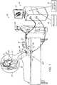
- FIG. 1is a schematic, pictorial illustration of an impedance based Active Current Location (ACL) position sensing system 36, in accordance with an embodiment of the present invention.
- ACL system 36is used in determining the position of a mapping-catheter 30, which is fitted at the distal end of a shaft 22, as seen in an inset 25.
- Mapping-catheter 30is inserted by physician 56 into an internal body cavity, such as a chamber of a heart 38 of a patient 40.
- mapping-catheter 30is used for diagnostics, such as spatially mapping the heart, and mapping electrical potentials in the heart prior to performing an ablation of heart tissue.
- Other types of catheters or other intrabody devicesmay alternatively be used for other purposes, by themselves or in conjunction with other treatment devices.
- Mapping-catheter 30comprises multiple sensing-electrodes 32, seen in an inset 25.
- Sensing-electrodes 32are connected by wires through shaft 22 to driver circuitry 44 connected to a processor 46 that is included in a console 24, whereas driver circuitry 44 drives sensing-electrodes 32 as commanded by processor 46.
- Processor 46is typically a general-purpose computer, with suitable front end, interface circuits for receiving signals from ACL patches 60P, and appropriate signal processing circuits.
- driver circuitry 44is connected by wires through cable 39 to six ACL electrodes attached to the skin of the patient, which are named hereinafter ACL patches 60, 62, 64, 66, 68 and 70, or collectively named hereinafter "ACL patches 60P'. As seen, ACL patches 60P are placed at the chest and back around heart 38 of patient 40.
- Each of six ACL patches 60Preceives position signals from each of the one or more sensing-electrodes 32 fitted at mapping-catheter 30, indicative of the position of the one or more sensing-electrodes 32.
- the six position signalsare further processed by processor 46 to derive the positions of each of mapping-electrodes 32 inside heart 38 (namely the ACL method).
- Driver circuitry 44drives a display 52, which may show the positions of each of mapping-electrodes 32 inside heart 38.
- the method of electrode position sensing using ACL system 36is implemented in various medical applications, for example, in the CARTOTM system, produced by Biosense Webster Inc. (Irvine, California) and described in detail in U.S. Patents 7,756,576 , 7,869,865 , 7,848,787 , and 8,456,182 whose disclosures are all incorporated herein by reference.
- the number of ACL patchescan be larger than six, whereas using six ACL patches is described by way of example.
- Processor 46typically comprises a general-purpose computer, which is programmed in software to carry out the functions described herein.
- the softwaremay be downloaded to the computer in electronic form, over a network, for example, or it may, alternatively or additionally, be provided and/or stored on non-transitory tangible media, such as magnetic, optical, or electronic memory.
- Position sensing system 36may be used with probes similar to mapping-catheter 30 in other body cavities.
- system 36includes other elements, which are not shown in the figures for the sake of simplicity, and which are referred to as necessary in the following description.
- system 36may include an ECG monitor, coupled to receive signals from one or more body surface ECG electrodes, so as to provide an ECG synchronization signal to console 24.
- system 36there may comprise one or more additional catheters, such as an ablation catheter and/or additional sensing-catheter, which, as said, are not shown for clarity.
- the configuration of Fig. 1is an example configuration, which is chosen purely for the sake of conceptual clarity. In alternative embodiments, any other suitable configuration can also be used.
- Processor 46comprises typically a general-purpose processor, which is programmed in software to carry out the functions described herein.
- the softwaremay be downloaded to the processor in electronic form, over a network, for example, or it may, alternatively or additionally, be provided and/or stored on tangible media, such as magnetic, optical, or electronic memory.
- Figs. 2A and 2Bare schematic, pictorial illustration of a selection process of three least-correlated ACL patches in an impedance ACL method, in accordance with an embodiment of the present invention.
- a patient torso 31is represented by a simplified cylindrical illustration.
- a position 87 inside torso 31is measured by six ACL patches, enumerated in Fig. 2A as P1-P6.
- Patches P1, P2 and P3are located on the top surface of torso 31 (i.e., 'chest'), while patches P4, P5 and P6 are located on the bottom surface of torso 31 (i.e., 'back').
- the two groups of patchesare separated by a typical height denoted in Fig. 2A as 'h'. This separation ensures that any position 34 in torso 31 volume could be reliably spanned by a coordinate space defined by the six ACL patches and an arbitrary origin in space.
- processor 46Prior to processor 46 selecting three ACL patches, position signals are measured with all ACL patches P1-P6 and recorded as a catheter is being moved about a region 87 in a heart. As explained below, for any given region 87 on an intra-body path that mapping-catheter 30 takes, processor 46 selects three ACL patches, which measure least-correlated change in position signal as the catheter moves. In other words, when one ACL patch shows a changing position signal as catheter 30 moves, while another patch shows little or no change in position signal, one of these ACL patches is selected by processor 46 as one of the three of the subgroup for the given region.
- a distance between a patch and a sensing electrode that changes by little or none when the sensing electrode movesindicates of a suitable patch. Indeed, the little or no change in distance will manifest in little or no change in the position signal measured from that patch, as a change in such signal is largely proportional to a change in the distance.
- Fig. 2Bexemplifies the selection of three ACL patches for regions 87A and 87B, out of six ACL patches P1-P6.
- region 87Alies on a line that is defined by a catheter 30 moving collinearly with a line connecting ACL patches P1 and P3. Maximal change in position signal is expected on electrodes P1/P3 (which should show anti-correlated signals).
- connecting region 87A and positions of patches P2 and P5 by lineswould form two largely mutually orthogonal axes relative to a line-axis defined by locations of patches P1 and P3.
- a resulting nearly orthogonal coordinate system 88is defined by patches P1/P3, P2 and P5, which should be sufficient for processor to accurately triangulate region 87A.
- region 87Blies on a line that is defined by a catheter 30 that moves collinearly with a line connecting ACL patch P1 and point 89 on the line connecting patches P5 and P6. Maximal change in position signal is expected on electrodes P1. As seen, at region 87B, electrode-patches P2 and P4 would form two largely mutually orthogonal line-axes relative to the line-axis connecting P1 and point 89. Thus, a nearly orthogonal coordinate system 90 is defined by P1, P2 and P4, which should be sufficient for processor 46 to accurately triangulate region 87B.
- the example pictorial illustration shown in Figs. 2A and 2Bare chosen purely for the sake of conceptual clarity.
- the number of ACL patchescan vary and be larger than six.
- the selected partial subset least-correlated ACL patchesmay include more than three patches.
- selecting three 'most orthogonal' out of six ACL patches as described in Figs. 2A and 2Bis brought by way of example.
- the three least correlated patcheswill be selected with relation to a fourth patch that serves as a common ground.
- Fig. 3is a flow chart schematically illustrating a method for obtaining a position of an electrode in the heart, in accordance with an embodiment of the present invention.
- the processbegins with an extraction phase 110, after which the system is operated in a tracking phase 112.
- the two phasesmay run during at least part of time in parallel, subject to available computation resources.
- Extraction phase 110begins with processor 46 receiving six-position signals from ACL patches 60P, indicative of a position of a sensing-electrode 32 in heart 38, at a receiving step 92.
- processor 46identifies subset of three 'most orthogonal' ACL patches, at an identification step 94.
- processor 46maintains the three least-correlated signals (named collectively the 'orthogonal' signal) of the original six ones.
- Processor 46further tests the validity, or quality of the 'most orthogonal' signal against encoded criteria, at an examination step 98. If the examination results in a rejection, processor 46 ignores the 'most orthogonal' signal and the process loops to receive a new six dependent position-signal, at a decision step 100. If the examination results in an acceptance, processor 46 further stores the "most orthogonal' signal for future use, at a storing step 102. The process than loops back to step 92, to receive another six-position signal, for example from another sensing-electrode, or from a new region of heart 38, until mapping is completed.
- processor 46selects (i.e., retrieves) per each given region the three 'most orthogonal' patches stored in step 82.
- the systemoperates sensing-electrode 32 on catheter to inject electrical current and the 'most orthogonal' patches to measure impedances, at a measurement step 104. Based on the measured impedances, processor 46 derives an exact electrode position, at a determining step 108.
- FIG. 3The example flow chart shown in Fig. 3 is chosen purely for the sake of conceptual clarity. In alternative embodiments, additional steps may be performed, such as calibration steps and/or adjustment steps.
- the number of ACL patchescan vary and be larger than six.
- the selected partial subset least-correlated ACL patchesmay include more than three patches.
- processor 46would further store, to begin with, the identity of a fourth patch that was selected to serve as a common ground.
Landscapes
- Health & Medical Sciences (AREA)
- Life Sciences & Earth Sciences (AREA)
- Engineering & Computer Science (AREA)
- Molecular Biology (AREA)
- Animal Behavior & Ethology (AREA)
- Biophysics (AREA)
- Pathology (AREA)
- Biomedical Technology (AREA)
- Heart & Thoracic Surgery (AREA)
- Medical Informatics (AREA)
- Veterinary Medicine (AREA)
- Surgery (AREA)
- Physics & Mathematics (AREA)
- General Health & Medical Sciences (AREA)
- Public Health (AREA)
- Human Computer Interaction (AREA)
- Nuclear Medicine, Radiotherapy & Molecular Imaging (AREA)
- Radiology & Medical Imaging (AREA)
- Cardiology (AREA)
- Physiology (AREA)
- Measurement And Recording Of Electrical Phenomena And Electrical Characteristics Of The Living Body (AREA)
- Media Introduction/Drainage Providing Device (AREA)
Abstract
Description
- The present invention relates generally to systems and methods for tracking catheter position within a patient's heart, and specifically to impedance based cardiac position tracking systems and methods.
- Tracking the position of an intrabody mapping catheter is required in many cardiac procedures. For example,
U.S. Patent Application Publication 2017/0079542 describes a method for identifying an electrode tissue contact quality comprising positioning a catheter including an array of at least a first electrode and a second electrode affixed to the catheter and having a known inter-electrode spacing in the vicinity of a cardiac tissue, wherein each electrode pair is configured to be orthogonal to a surface of a cardiac tissue substrate. The method comprises measuring a first rate of change in electrogram amplitude from the first electrode, measuring a second rate of change in electrogram amplitude from the second electrode, calculating a difference between the first rate of change in electrogram amplitude and the second rate of change in electrogram amplitude to obtain a difference between rate of changes, and correlating the difference in rate of changes value to whether the first electrode is in contact with the cardiac tissue. - As another example,
U.S. Patent 5,983,126 describes a system and method for catheter location mapping, and related procedures. Three substantially orthogonal alternating signals are applied through the patient, directed substantially toward the area of interest to be mapped, such as patient's heart. A catheter is equipped with at least a measuring electrode, which for cardiac procedures is positioned at various locations either against the patient's heart wall, or within a coronary vein or artery. A voltage is sensed between the catheter tip and a reference electrode, preferably a surface electrode on the patient, which voltage signal has components corresponding to the three orthogonally applied current signals. Three processing channels are used to separate out the three components as x, y and z signals, from which calculations are made for determination of the three-dimensional location of the catheter tip within the body. U.S. Patent 8,611,991 describes a method for taking electrical impedance tomography measurements using multiple electrodes located at selected positions external to a volume of a subject body. Multiple orthogonal or near-orthogonal signals are introduced simultaneously by way of selected different electrodes and resultant predetermined responses (if any) at receiving electrodes are recorded or determined. The signals are encoded using the technique of code division multiplexing and received signals at each receiving electrode are cross-correlated with original signals to determine the contribution of each original signal to a composite received signal.U.S. Patent 5,899,860 describes a system for determining the position of a catheter inside the body of a patient. A correction function is determined from the difference between calibration positions derived from received location signals and known, true calibration positions, whereupon catheter positions, derived from received position signals, are corrected in subsequent measurement stages according to the correction function.U.S. Patent 5,697,377 describes techniques for catheter location mapping. Three substantially orthogonal alternating signals are applied through the patient, directed substantially toward the area of interest to be mapped. A catheter is equipped with at least a measuring electrode. A voltage is sensed between the catheter tip and a reference electrode, preferably a surface electrode on the patient, which voltage signal has components corresponding to the three orthogonal applied current signals. Three processing channels are used to separate out the three components as x, y and z signals, from which calculations are made for determination of the three-dimensional location of the catheter tip within the body.- An embodiment of the present invention that is described herein provides a position tracking system including an electrical interface and a processor. The electrical interface is configured to communicate with one or more electrodes that are coupled to a distal end of a probe inserted into a heart of a patient. The electrical interface is further configured to receive, from a plurality of electrode-patches attached to a skin of the patient, position signals that are indicative of positions of the one or more electrodes in the heart. The processor is configured to select, based on the position signals, a partial subset of the electrode-patches whose position signals are least-correlated with one another, and to estimate a position of at least one of the electrodes in the heart, based on the position signals received from the selected partial subset of the electrode-patches.
- In some embodiments, the processor is configured to select the least-correlated electrode-patches by sequentially selecting one electrode-patch from each possible pair of the electrode-patches, such that the one electrode-patch of the pair measures a smallest change in position signal as the other electrode-patch measures a changing position signal while the distal end moves in the heart.
- In some embodiments, the processor is configured to select different subsets of least-correlated position signals for different regions in the heart.
- In an embodiment, the processor is configured to provide three least-correlated position signals as elements of a 3x3 matrix.
- In another embodiment, the electrical interface is further configured to receive the position signals from the one or more electrodes that are coupled to the distal end of the probe.
- There is additionally provided, in accordance with an embodiment of the present invention, a position tracking method, the method including communicating with one or more electrodes that are coupled to a distal end of a probe inserted into a heart of a patient. Position signals that are indicative of positions of the one or more electrodes in the heart are received from a plurality of electrode-patches attached to a skin of the patient. Based on the position signals, a partial subset of the electrode-patches whose position signals are least-correlated with one another is selected. Based on the position signals received from the selected partial subset of the electrode-patches, a position of at least one of the electrodes in the heart is estimated.
- The present invention will be more fully understood from the following detailed description of the embodiments thereof, taken together with the drawings in which:
Fig. 1 is a schematic, pictorial illustration of an impedance based Active Current Location (ACL) position tracking system, in accordance with an embodiment of the present invention;Figs. 2A and 2B are schematic, pictorial illustrations of a selection process of three least-correlated ACL patches in an impedance ACL method, in accordance with an embodiment of the present invention; andFig. 3 is a flow chart schematically illustrating a method for obtaining a position of an electrode in the heart, in accordance with an embodiment of the present invention.- Several approaches may be used for tracking a position inside a body of a patient. Impedance-based position tracking methods, for example, may either assume that measured impedances between one or more intra-body sensing-electrodes and surface-electrodes are proportional to respective distances, or calibrate measured impedances by correlating the impedances with respective coordinates measured in advance. Voltage-based sensing methods, on the other hand, use the one or more intra-body sensing-electrodes for sensing surface-electrodes.
- Impedance-based position tracking systems typically measure impedances between a sensing-electrode and the surface-electrodes (named hereinafter 'electrode-patches') attached to the skin, and from these measurements derive a three-dimensional position coordinate of the sensing-electrode. In principle, three electrode-patches are sufficient for triangulating the position of a sensing-electrode, using well known methods described, for example, in
U.S. Patent 7,756,576 , whose disclosure is incorporated herein by reference. - Voltage-based position tracking systems typically measure voltages between a sensing-electrode and the electrode-patches (i.e., the sensing-electrodes are used for measuring voltages induced between ACL patches). In this case, four electrode-patches are sufficient for triangulating the position of a sensing-electrode, so as to generate three different voltage gradients that the sensing-electrodes measures.
- In practice, either three-electrode-patches schemes with impedance-based methods, or four-electrode-patches schemes with voltage-based methods, achieve insufficient position accuracy. Thus, to accurately measure an intra-body position of a sensing-electrode, impedance-based position tracking systems, such as the Active Current Location (ACL) system (produced by Biosense Webster, Inc.), use a larger number of patches. Voltage-based position tracking systems, such as the CARTO4® (produced by Biosense Webster, Inc.) also use larger number of patches. An ACL system, for example, either impedance based or voltage based, may use six or more patches, named hereinafter 'ACL patches.' The ACL patches are attached to the patient skin on the chest and the back, an arrangement found to consistently and reliably triangulate any given three-dimensional position in a heart. The position of the sensing-electrodes is given in a coordinate system defined by the six ACL patches and an arbitrary origin within the three-dimensional space.
- Deriving in real-time accurate electrode-positions from impedance-based measurements puts demanding computational requirements on multiple-patch tracking position systems. Unless expansive computing hardware is employed, the complicated calculations involved may cause disturbing delays, for example between necessary updates of a position map that is presented to the physician on a display. Such delays may result in inaccuracies in maps, especially with maps of a moving organ like a chamber of a heart.
- Embodiments of the present invention that are described herein provide a method that enables using position tracking systems to measure a position of a sensing-electrode both accurately enough and with reduced complexity of calculations. In some embodiments, position-signals (e.g., electrical currents or impedances) measured with all ACL patches (e.g., six or more) are recorded while one or more sensing-electrodes are being moved through multiple regions in a heart. For any given region, a processor in the position tracking system selects a partial sub-set of least-correlated electrode-patches (also named in the description 'most orthogonal', whereas both terms mean the same). By way of example, three "most orthogonal" of six or more ACL patches are selected. In principle, it is possible that more than three "most orthogonal" ACL patches exist. In practice, however, the benefit of exceeding three patches is small (i.e., not "cost-effective" computationally wise).
- The identity of patches making-up a sub-set of least-correlated electrode-patches per given region may be different for impedance and voltage ACL methods. The reason is that in the impedance ACL method, the patches are selected with relation to the sensing-electrodes, whereas in the voltage ACL method the three patches are selected with relation to a fourth patch that serves as a common ground, and whose identity is saved as well. In some embodiments the fourth patch is selected once, so its identity is known and does not need to be restored every time that three newly selected ACL patches have their identity stored.
- For a given region of the heart, the processor typically selects a partial subset of the electrode-patches whose position signals are least-correlated with one another (i.e., 'most orthogonal'). The "most orthogonal" ACL patches are selected by examining which pairs of ACL patches provide position-signals that are least-correlated with one another, as the catheter moves about the given region. In other words, when one ACL patch shows a change in signal as the sensing electrode moves, while another patch shows little or no signal change, one of the two ACL patches is selected as one of the nearly orthogonal triplet sub-group for the given region.
- The identity of the 'most orthogonal' ACL patches will typically change according to the region being considered and may also change with time. Nevertheless, using such least-correlated ACL patches subgroup (e.g., three) to find the catheter position, instead of, for example, of using data from all (e.g., six) ACL patches, will improve accuracy as the 'most orthogonal' ACL patches provide the required accuracy without degrading the measurement by additional measurement errors that the other, far less significant patches, would still add. Furthermore, using fewer ACL patches reduces the complexity of the real-time calculation. From the computational point of view, by way of example, this largely amounts to processing 3x3 matrices instead of 6x6 matrices, which may yield a significant reduction in the required computational power.
- The disclosed technique, thus, has the distinct advantages of (a) improving the position-tracking accuracy, and (b) substantially simplifying real-time calculations. The second advantage will manifest itself, for example, in the reduction of occurrences of disturbing delays between each position measurement step and its subsequent update on a map on a display. The elimination of delays may be especially beneficial for improving the accuracy of a resulting electro-anatomical map of a moving organ such as a heart. Another possible advantage is the reduced requirement on computation hardware in position tracking systems, which may reduce the costs of such medical systems.
Fig. 1 is a schematic, pictorial illustration of an impedance based Active Current Location (ACL)position sensing system 36, in accordance with an embodiment of the present invention.ACL system 36 is used in determining the position of a mapping-catheter 30, which is fitted at the distal end of ashaft 22, as seen in aninset 25. Mapping-catheter 30 is inserted byphysician 56 into an internal body cavity, such as a chamber of aheart 38 of apatient 40. Typically, mapping-catheter 30 is used for diagnostics, such as spatially mapping the heart, and mapping electrical potentials in the heart prior to performing an ablation of heart tissue. Other types of catheters or other intrabody devices may alternatively be used for other purposes, by themselves or in conjunction with other treatment devices.- Mapping-
catheter 30 comprises multiple sensing-electrodes 32, seen in aninset 25. Sensing-electrodes 32 are connected by wires throughshaft 22 todriver circuitry 44 connected to aprocessor 46 that is included in aconsole 24, whereasdriver circuitry 44 drives sensing-electrodes 32 as commanded byprocessor 46.Processor 46 is typically a general-purpose computer, with suitable front end, interface circuits for receiving signals fromACL patches 60P, and appropriate signal processing circuits. For that,driver circuitry 44 is connected by wires throughcable 39 to six ACL electrodes attached to the skin of the patient, which are named hereinafterACL patches ACL patches 60P'. As seen,ACL patches 60P are placed at the chest and back aroundheart 38 ofpatient 40. - Each of six
ACL patches 60P receives position signals from each of the one or more sensing-electrodes 32 fitted at mapping-catheter 30, indicative of the position of the one or more sensing-electrodes 32. The six position signals are further processed byprocessor 46 to derive the positions of each of mapping-electrodes 32 inside heart 38 (namely the ACL method).Driver circuitry 44 drives adisplay 52, which may show the positions of each of mapping-electrodes 32 insideheart 38. - The method of electrode position sensing using
ACL system 36 is implemented in various medical applications, for example, in the CARTO™ system, produced by Biosense Webster Inc. (Irvine, California) and described in detail inU.S. Patents 7,756,576 ,7,869,865 ,7,848,787 , and8,456,182 whose disclosures are all incorporated herein by reference. The number of ACL patches can be larger than six, whereas using six ACL patches is described by way of example. Processor 46 typically comprises a general-purpose computer, which is programmed in software to carry out the functions described herein. The software may be downloaded to the computer in electronic form, over a network, for example, or it may, alternatively or additionally, be provided and/or stored on non-transitory tangible media, such as magnetic, optical, or electronic memory.Position sensing system 36 may be used with probes similar to mapping-catheter 30 in other body cavities. Typically,system 36 includes other elements, which are not shown in the figures for the sake of simplicity, and which are referred to as necessary in the following description. For example,system 36 may include an ECG monitor, coupled to receive signals from one or more body surface ECG electrodes, so as to provide an ECG synchronization signal to console 24. As another example,system 36 there may comprise one or more additional catheters, such as an ablation catheter and/or additional sensing-catheter, which, as said, are not shown for clarity. Thus, the configuration ofFig. 1 is an example configuration, which is chosen purely for the sake of conceptual clarity. In alternative embodiments, any other suitable configuration can also be used.Processor 46 comprises typically a general-purpose processor, which is programmed in software to carry out the functions described herein. The software may be downloaded to the processor in electronic form, over a network, for example, or it may, alternatively or additionally, be provided and/or stored on tangible media, such as magnetic, optical, or electronic memory.Figs. 2A and 2B are schematic, pictorial illustration of a selection process of three least-correlated ACL patches in an impedance ACL method, in accordance with an embodiment of the present invention. InFig. 2A , for clarity, apatient torso 31 is represented by a simplified cylindrical illustration. Aposition 87 insidetorso 31 is measured by six ACL patches, enumerated inFig. 2A as P1-P6. Patches P1, P2 and P3 are located on the top surface of torso 31 (i.e., 'chest'), while patches P4, P5 and P6 are located on the bottom surface of torso 31 (i.e., 'back'). In such arrangement, the two groups of patches are separated by a typical height denoted inFig. 2A as 'h'. This separation ensures that any position 34 intorso 31 volume could be reliably spanned by a coordinate space defined by the six ACL patches and an arbitrary origin in space.- Prior to
processor 46 selecting three ACL patches, position signals are measured with all ACL patches P1-P6 and recorded as a catheter is being moved about aregion 87 in a heart. As explained below, for any givenregion 87 on an intra-body path that mapping-catheter 30 takes,processor 46 selects three ACL patches, which measure least-correlated change in position signal as the catheter moves. In other words, when one ACL patch shows a changing position signal ascatheter 30 moves, while another patch shows little or no change in position signal, one of these ACL patches is selected byprocessor 46 as one of the three of the subgroup for the given region. - From geometrical point of view, a distance between a patch and a sensing electrode that changes by little or none when the sensing electrode moves, indicates of a suitable patch. Indeed, the little or no change in distance will manifest in little or no change in the position signal measured from that patch, as a change in such signal is largely proportional to a change in the distance.
Fig. 2B exemplifies the selection of three ACL patches forregions region 87A lies on a line that is defined by acatheter 30 moving collinearly with a line connecting ACL patches P1 and P3. Maximal change in position signal is expected on electrodes P1/P3 (which should show anti-correlated signals). As seen, connectingregion 87A and positions of patches P2 and P5 by lines would form two largely mutually orthogonal axes relative to a line-axis defined by locations of patches P1 and P3. Thus, a resulting nearly orthogonal coordinatesystem 88 is defined by patches P1/P3, P2 and P5, which should be sufficient for processor to accurately triangulateregion 87A.- In another exemplified case,
region 87B lies on a line that is defined by acatheter 30 that moves collinearly with a line connecting ACL patch P1 andpoint 89 on the line connecting patches P5 and P6. Maximal change in position signal is expected on electrodes P1. As seen, atregion 87B, electrode-patches P2 and P4 would form two largely mutually orthogonal line-axes relative to the line-axis connecting P1 andpoint 89. Thus, a nearly orthogonal coordinatesystem 90 is defined by P1, P2 and P4, which should be sufficient forprocessor 46 to accurately triangulateregion 87B. - The example pictorial illustration shown in
Figs. 2A and 2B are chosen purely for the sake of conceptual clarity. For example, the number of ACL patches can vary and be larger than six. The selected partial subset least-correlated ACL patches may include more than three patches. Thus, selecting three 'most orthogonal' out of six ACL patches as described inFigs. 2A and 2B is brought by way of example. As noted above, for a voltage-based tracking system, the three least correlated patches will be selected with relation to a fourth patch that serves as a common ground. Fig. 3 is a flow chart schematically illustrating a method for obtaining a position of an electrode in the heart, in accordance with an embodiment of the present invention. The process begins with anextraction phase 110, after which the system is operated in atracking phase 112. The two phases may run during at least part of time in parallel, subject to available computation resources.Extraction phase 110 begins withprocessor 46 receiving six-position signals fromACL patches 60P, indicative of a position of a sensing-electrode 32 inheart 38, at a receiving step 92.- Next,
processor 46 identifies subset of three 'most orthogonal' ACL patches, at anidentification step 94. At a followingextraction step 96,processor 46 maintains the three least-correlated signals (named collectively the 'orthogonal' signal) of the original six ones.Processor 46 further tests the validity, or quality of the 'most orthogonal' signal against encoded criteria, at anexamination step 98. If the examination results in a rejection,processor 46 ignores the 'most orthogonal' signal and the process loops to receive a new six dependent position-signal, at adecision step 100. If the examination results in an acceptance,processor 46 further stores the "most orthogonal' signal for future use, at a storingstep 102. The process than loops back to step 92, to receive another six-position signal, for example from another sensing-electrode, or from a new region ofheart 38, until mapping is completed. - In
tracking phase 112,processor 46 selects (i.e., retrieves) per each given region the three 'most orthogonal' patches stored in step 82. The system operates sensing-electrode 32 on catheter to inject electrical current and the 'most orthogonal' patches to measure impedances, at ameasurement step 104. Based on the measured impedances,processor 46 derives an exact electrode position, at a determiningstep 108. - The example flow chart shown in
Fig. 3 is chosen purely for the sake of conceptual clarity. In alternative embodiments, additional steps may be performed, such as calibration steps and/or adjustment steps. The number of ACL patches can vary and be larger than six. The selected partial subset least-correlated ACL patches may include more than three patches. When voltage-based tracking is used,processor 46 would further store, to begin with, the identity of a fourth patch that was selected to serve as a common ground. - Although the embodiments described herein mainly address improvements in impedance-based position tracking of a cardiac catheter in a heart, the methods and systems described herein can also be used in other applications.
- It will thus be appreciated that the embodiments described above are cited by way of example, and that the present invention is not limited to what has been particularly shown and described hereinabove. Rather, the scope of the present invention includes both combinations and sub-combinations of the various features described hereinabove, as well as variations and modifications thereof which would occur to persons skilled in the art upon reading the foregoing description and which are not disclosed in the prior art. Documents incorporated by reference in the present patent application are to be considered an integral part of the application except that to the extent any terms are defined in these incorporated documents in a manner that conflicts with the definitions made explicitly or implicitly in the present specification, only the definitions in the present specification should be considered.
Claims (10)
- A position tracking system, comprising:an electrical interface configured to:communicate with one or more electrodes that are coupled to a distal end of a probe inserted into a heart of a patient; andreceive, from a plurality of electrode-patches attached to a skin of the patient, position signals that are indicative of positions of the one or more electrodes in the heart; anda processor, configured to:select, based on the position signals, a partial subset of the electrode-patches whose position signals are least-correlated with one another; andestimate a position of at least one of the electrodes in the heart, based on the position signals received from the selected partial subset of the electrode-patches.
- The system according to claim 1, wherein the processor is configured to select the least-correlated electrode-patches by sequentially selecting one electrode-patch from each possible pair of the electrode-patches, such that the one electrode-patch of the pair measures a smallest change in position signal as the other electrode-patch measures a changing position signal while the distal end moves in the heart.
- The system according to claim 1, wherein the processor is configured to select different subsets of least-correlated position signals for different regions in the heart.
- The system according to claim 1, wherein the processor is configured to provide three least-correlated position signals as elements of a 3x3 matrix.
- The system according to claim 1, wherein the electrical interface is further configured to receive the position signals from the one or more electrodes that are coupled to the distal end of the probe.
- A position tracking method, the method comprising:communicating with one or more electrodes that are coupled to a distal end of a probe inserted into a heart of a patient;receiving, from a plurality of electrode-patches attached to a skin of the patient, position signals that are indicative of positions of the one or more electrodes in the heart;based on the position signals, selecting a partial subset of the electrode-patches whose position signals are least-correlated with one another; andbased on the position signals received from the selected partial subset of the electrode-patches, estimating a position of at least one of the electrodes in the heart.
- The method according to claim 6, wherein selecting the least-correlated electrode-patches comprises sequentially selecting one electrode-patch from each possible pair of the electrode-patches, such that the one electrode-patch of the pair measures a smallest change in position signal as the other electrode-patch measures a changing position signal while the distal end moves in the heart.
- The method according to claim 6, wherein selecting the least-correlated position signals comprises selecting different subsets of least-correlated position signals for different regions in the heart.
- The method according to claim 6, and comprising providing, in a processor, three least-correlated position signals as elements of a 3x3 matrix.
- The method according to claim 6, and comprising receiving the position signals also from the one or more electrodes that are coupled to the distal end of the probe.
Applications Claiming Priority (1)
| Application Number | Priority Date | Filing Date | Title |
|---|---|---|---|
| US16/010,573US11185274B2 (en) | 2018-06-18 | 2018-06-18 | Identifying orthogonal sets of active current location (ACL) patches |
Publications (2)
| Publication Number | Publication Date |
|---|---|
| EP3583895A1true EP3583895A1 (en) | 2019-12-25 |
| EP3583895B1 EP3583895B1 (en) | 2023-07-05 |
Family
ID=67105693
Family Applications (1)
| Application Number | Title | Priority Date | Filing Date |
|---|---|---|---|
| EP19180644.7AActiveEP3583895B1 (en) | 2018-06-18 | 2019-06-17 | Identifying orthogonal sets of active current location (acl) patches |
Country Status (7)
| Country | Link |
|---|---|
| US (1) | US11185274B2 (en) |
| EP (1) | EP3583895B1 (en) |
| JP (1) | JP7387303B2 (en) |
| CN (1) | CN110613453B (en) |
| AU (1) | AU2019203905A1 (en) |
| CA (1) | CA3045881A1 (en) |
| IL (1) | IL266912B (en) |
Families Citing this family (2)
| Publication number | Priority date | Publication date | Assignee | Title |
|---|---|---|---|---|
| CN114041877B (en)* | 2022-01-06 | 2022-04-01 | 南京惠积信息科技有限公司 | Three-dimensional catheter positioning system based on impedance information |
| CN114795183A (en)* | 2022-04-27 | 2022-07-29 | 四川锦江电子科技有限公司 | A method and device for combining magnetoelectric positioning and tracking |
Citations (10)
| Publication number | Priority date | Publication date | Assignee | Title |
|---|---|---|---|---|
| US5697377A (en) | 1995-11-22 | 1997-12-16 | Medtronic, Inc. | Catheter mapping system and method |
| US5899860A (en) | 1996-09-12 | 1999-05-04 | Siemens Elema Ab | Method and device for determining the position of a catheter inside the body of a patient |
| WO2008108901A1 (en)* | 2006-12-28 | 2008-09-12 | Medtronic, Inc | Chronically-implantable active fixation medical electrical leads and related methods for non-fluoroscopic implantation |
| US7756576B2 (en) | 2005-08-26 | 2010-07-13 | Biosense Webster, Inc. | Position sensing and detection of skin impedance |
| US7848787B2 (en) | 2005-07-08 | 2010-12-07 | Biosense Webster, Inc. | Relative impedance measurement |
| US7869865B2 (en) | 2005-01-07 | 2011-01-11 | Biosense Webster, Inc. | Current-based position sensing |
| US20130066193A1 (en)* | 2011-09-13 | 2013-03-14 | Eric S. Olson | Catheter navigation using impedance and magnetic field measurements |
| US8456182B2 (en) | 2008-09-30 | 2013-06-04 | Biosense Webster, Inc. | Current localization tracker |
| US8611991B2 (en) | 2007-11-26 | 2013-12-17 | The University Of Cape Town | System and method for conducting multiplexed electrical impedance tomography |
| US20170079542A1 (en) | 2013-01-16 | 2017-03-23 | University Of Vermont | Catheters, systems, and related methods for mapping, minimizing, and treating cardiac fibrillation |
Family Cites Families (13)
| Publication number | Priority date | Publication date | Assignee | Title |
|---|---|---|---|---|
| US7885707B2 (en) | 2005-09-15 | 2011-02-08 | St. Jude Medical, Atrial Fibrillation Division, Inc. | Method of scaling navigation signals to account for impedance drift in tissue |
| US8494608B2 (en) | 2008-04-18 | 2013-07-23 | Medtronic, Inc. | Method and apparatus for mapping a structure |
| WO2009129477A1 (en)* | 2008-04-18 | 2009-10-22 | Medtronic, Inc. | Method and apparatus for mapping a structure |
| US9610118B2 (en)* | 2008-12-31 | 2017-04-04 | St. Jude Medical, Atrial Fibrillation Division, Inc. | Method and apparatus for the cancellation of motion artifacts in medical interventional navigation |
| US8478383B2 (en)* | 2010-12-14 | 2013-07-02 | Biosense Webster (Israel), Ltd. | Probe tracking using multiple tracking methods |
| US9629570B2 (en)* | 2013-11-21 | 2017-04-25 | Biosense Webster (Israel) Ltd. | Tracking of catheter from insertion point to heart using impedance measurements |
| US9572535B2 (en)* | 2013-12-05 | 2017-02-21 | Biosense Webster (Israel) Ltd. | Dynamic mapping point filtering using a pre-acquired image |
| US9615764B2 (en)* | 2014-11-03 | 2017-04-11 | Biosense Webster (Israel) Ltd | Real-time coloring of electrophysiological map |
| US10307078B2 (en) | 2015-02-13 | 2019-06-04 | Biosense Webster (Israel) Ltd | Training of impedance based location system using registered catheter images |
| WO2016181317A2 (en)* | 2015-05-12 | 2016-11-17 | Navix International Limited | Calculation of an ablation plan |
| US10410369B2 (en)* | 2016-04-15 | 2019-09-10 | Biosense Webster (Israel) Ltd. | Method and system for determining locations of electrodes on a patient body |
| US10667698B2 (en)* | 2016-05-12 | 2020-06-02 | Masayoshi Yoshida | Methods for estimating post-PCI fractional flow reserve |
| US10492704B2 (en)* | 2017-08-29 | 2019-12-03 | Biosense Webster (Israel) Ltd. | Medical patch for simultaneously sensing ECG signals and impedance-indicative electrical signals |
- 2018
- 2018-06-18USUS16/010,573patent/US11185274B2/enactiveActive
- 2019
- 2019-05-27ILIL266912Apatent/IL266912B/enunknown
- 2019-06-04AUAU2019203905Apatent/AU2019203905A1/ennot_activeAbandoned
- 2019-06-12CACA3045881Apatent/CA3045881A1/ennot_activeAbandoned
- 2019-06-17EPEP19180644.7Apatent/EP3583895B1/enactiveActive
- 2019-06-17JPJP2019111759Apatent/JP7387303B2/enactiveActive
- 2019-06-18CNCN201910525987.1Apatent/CN110613453B/enactiveActive
Patent Citations (11)
| Publication number | Priority date | Publication date | Assignee | Title |
|---|---|---|---|---|
| US5697377A (en) | 1995-11-22 | 1997-12-16 | Medtronic, Inc. | Catheter mapping system and method |
| US5983126A (en) | 1995-11-22 | 1999-11-09 | Medtronic, Inc. | Catheter location system and method |
| US5899860A (en) | 1996-09-12 | 1999-05-04 | Siemens Elema Ab | Method and device for determining the position of a catheter inside the body of a patient |
| US7869865B2 (en) | 2005-01-07 | 2011-01-11 | Biosense Webster, Inc. | Current-based position sensing |
| US7848787B2 (en) | 2005-07-08 | 2010-12-07 | Biosense Webster, Inc. | Relative impedance measurement |
| US7756576B2 (en) | 2005-08-26 | 2010-07-13 | Biosense Webster, Inc. | Position sensing and detection of skin impedance |
| WO2008108901A1 (en)* | 2006-12-28 | 2008-09-12 | Medtronic, Inc | Chronically-implantable active fixation medical electrical leads and related methods for non-fluoroscopic implantation |
| US8611991B2 (en) | 2007-11-26 | 2013-12-17 | The University Of Cape Town | System and method for conducting multiplexed electrical impedance tomography |
| US8456182B2 (en) | 2008-09-30 | 2013-06-04 | Biosense Webster, Inc. | Current localization tracker |
| US20130066193A1 (en)* | 2011-09-13 | 2013-03-14 | Eric S. Olson | Catheter navigation using impedance and magnetic field measurements |
| US20170079542A1 (en) | 2013-01-16 | 2017-03-23 | University Of Vermont | Catheters, systems, and related methods for mapping, minimizing, and treating cardiac fibrillation |
Also Published As
| Publication number | Publication date |
|---|---|
| JP7387303B2 (en) | 2023-11-28 |
| US20190380608A1 (en) | 2019-12-19 |
| IL266912A (en) | 2019-08-29 |
| CA3045881A1 (en) | 2019-12-18 |
| US11185274B2 (en) | 2021-11-30 |
| IL266912B (en) | 2022-03-01 |
| EP3583895B1 (en) | 2023-07-05 |
| CN110613453B (en) | 2024-06-04 |
| JP2019217281A (en) | 2019-12-26 |
| AU2019203905A1 (en) | 2020-01-16 |
| CN110613453A (en) | 2019-12-27 |
Similar Documents
| Publication | Publication Date | Title |
|---|---|---|
| EP3643223B1 (en) | Combined active current location (acl) and tissue proximity indication (tpi) system | |
| EP3607879B1 (en) | Nonlinear electric field location system | |
| CN107666856B (en) | Magnetic sensing to provide geometric information | |
| EP3563763B1 (en) | Improved active voltage location (avl) resolution | |
| CN111265216A (en) | Coronary Sinus (CS) catheter movement detection | |
| EP3583895B1 (en) | Identifying orthogonal sets of active current location (acl) patches | |
| EP3505061A1 (en) | Improving impedance-based position tracking performance using principal component analysis | |
| JP7247055B2 (en) | Reduction of capacitive effects in active current position (ACL) |
Legal Events
| Date | Code | Title | Description |
|---|---|---|---|
| PUAI | Public reference made under article 153(3) epc to a published international application that has entered the european phase | Free format text:ORIGINAL CODE: 0009012 | |
| STAA | Information on the status of an ep patent application or granted ep patent | Free format text:STATUS: THE APPLICATION HAS BEEN PUBLISHED | |
| AK | Designated contracting states | Kind code of ref document:A1 Designated state(s):AL AT BE BG CH CY CZ DE DK EE ES FI FR GB GR HR HU IE IS IT LI LT LU LV MC MK MT NL NO PL PT RO RS SE SI SK SM TR | |
| AX | Request for extension of the european patent | Extension state:BA ME | |
| STAA | Information on the status of an ep patent application or granted ep patent | Free format text:STATUS: REQUEST FOR EXAMINATION WAS MADE | |
| 17P | Request for examination filed | Effective date:20200608 | |
| RBV | Designated contracting states (corrected) | Designated state(s):AL AT BE BG CH CY CZ DE DK EE ES FI FR GB GR HR HU IE IS IT LI LT LU LV MC MK MT NL NO PL PT RO RS SE SI SK SM TR | |
| RIC1 | Information provided on ipc code assigned before grant | Ipc:A61B 34/20 20160101ALN20220712BHEP Ipc:A61B 5/053 20060101ALI20220712BHEP Ipc:A61B 5/06 20060101AFI20220712BHEP | |
| GRAP | Despatch of communication of intention to grant a patent | Free format text:ORIGINAL CODE: EPIDOSNIGR1 | |
| STAA | Information on the status of an ep patent application or granted ep patent | Free format text:STATUS: GRANT OF PATENT IS INTENDED | |
| RIC1 | Information provided on ipc code assigned before grant | Ipc:A61B 34/20 20160101ALN20220819BHEP Ipc:A61B 5/053 20060101ALI20220819BHEP Ipc:A61B 5/06 20060101AFI20220819BHEP | |
| INTG | Intention to grant announced | Effective date:20220915 | |
| GRAJ | Information related to disapproval of communication of intention to grant by the applicant or resumption of examination proceedings by the epo deleted | Free format text:ORIGINAL CODE: EPIDOSDIGR1 | |
| STAA | Information on the status of an ep patent application or granted ep patent | Free format text:STATUS: REQUEST FOR EXAMINATION WAS MADE | |
| GRAP | Despatch of communication of intention to grant a patent | Free format text:ORIGINAL CODE: EPIDOSNIGR1 | |
| STAA | Information on the status of an ep patent application or granted ep patent | Free format text:STATUS: GRANT OF PATENT IS INTENDED | |
| INTC | Intention to grant announced (deleted) | ||
| RIC1 | Information provided on ipc code assigned before grant | Ipc:A61B 34/20 20160101ALN20230113BHEP Ipc:A61B 5/053 20060101ALI20230113BHEP Ipc:A61B 5/06 20060101AFI20230113BHEP | |
| INTG | Intention to grant announced | Effective date:20230203 | |
| RIC1 | Information provided on ipc code assigned before grant | Ipc:A61B 34/20 20160101ALN20230124BHEP Ipc:A61B 5/053 20060101ALI20230124BHEP Ipc:A61B 5/06 20060101AFI20230124BHEP | |
| GRAS | Grant fee paid | Free format text:ORIGINAL CODE: EPIDOSNIGR3 | |
| GRAA | (expected) grant | Free format text:ORIGINAL CODE: 0009210 | |
| STAA | Information on the status of an ep patent application or granted ep patent | Free format text:STATUS: THE PATENT HAS BEEN GRANTED | |
| AK | Designated contracting states | Kind code of ref document:B1 Designated state(s):AL AT BE BG CH CY CZ DE DK EE ES FI FR GB GR HR HU IE IS IT LI LT LU LV MC MK MT NL NO PL PT RO RS SE SI SK SM TR | |
| REG | Reference to a national code | Ref country code:CH Ref legal event code:EP | |
| REG | Reference to a national code | Ref country code:AT Ref legal event code:REF Ref document number:1584051 Country of ref document:AT Kind code of ref document:T Effective date:20230715 | |
| REG | Reference to a national code | Ref country code:DE Ref legal event code:R096 Ref document number:602019032014 Country of ref document:DE | |
| REG | Reference to a national code | Ref country code:IE Ref legal event code:FG4D | |
| REG | Reference to a national code | Ref country code:LT Ref legal event code:MG9D | |
| REG | Reference to a national code | Ref country code:NL Ref legal event code:MP Effective date:20230705 | |
| REG | Reference to a national code | Ref country code:AT Ref legal event code:MK05 Ref document number:1584051 Country of ref document:AT Kind code of ref document:T Effective date:20230705 | |
| PG25 | Lapsed in a contracting state [announced via postgrant information from national office to epo] | Ref country code:NL Free format text:LAPSE BECAUSE OF FAILURE TO SUBMIT A TRANSLATION OF THE DESCRIPTION OR TO PAY THE FEE WITHIN THE PRESCRIBED TIME-LIMIT Effective date:20230705 | |
| PG25 | Lapsed in a contracting state [announced via postgrant information from national office to epo] | Ref country code:GR Free format text:LAPSE BECAUSE OF FAILURE TO SUBMIT A TRANSLATION OF THE DESCRIPTION OR TO PAY THE FEE WITHIN THE PRESCRIBED TIME-LIMIT Effective date:20231006 | |
| PG25 | Lapsed in a contracting state [announced via postgrant information from national office to epo] | Ref country code:ES Free format text:LAPSE BECAUSE OF FAILURE TO SUBMIT A TRANSLATION OF THE DESCRIPTION OR TO PAY THE FEE WITHIN THE PRESCRIBED TIME-LIMIT Effective date:20230705 | |
| PG25 | Lapsed in a contracting state [announced via postgrant information from national office to epo] | Ref country code:IS Free format text:LAPSE BECAUSE OF FAILURE TO SUBMIT A TRANSLATION OF THE DESCRIPTION OR TO PAY THE FEE WITHIN THE PRESCRIBED TIME-LIMIT Effective date:20231105 | |
| PG25 | Lapsed in a contracting state [announced via postgrant information from national office to epo] | Ref country code:SE Free format text:LAPSE BECAUSE OF FAILURE TO SUBMIT A TRANSLATION OF THE DESCRIPTION OR TO PAY THE FEE WITHIN THE PRESCRIBED TIME-LIMIT Effective date:20230705 Ref country code:RS Free format text:LAPSE BECAUSE OF FAILURE TO SUBMIT A TRANSLATION OF THE DESCRIPTION OR TO PAY THE FEE WITHIN THE PRESCRIBED TIME-LIMIT Effective date:20230705 Ref country code:PT Free format text:LAPSE BECAUSE OF FAILURE TO SUBMIT A TRANSLATION OF THE DESCRIPTION OR TO PAY THE FEE WITHIN THE PRESCRIBED TIME-LIMIT Effective date:20231106 Ref country code:NO Free format text:LAPSE BECAUSE OF FAILURE TO SUBMIT A TRANSLATION OF THE DESCRIPTION OR TO PAY THE FEE WITHIN THE PRESCRIBED TIME-LIMIT Effective date:20231005 Ref country code:LV Free format text:LAPSE BECAUSE OF FAILURE TO SUBMIT A TRANSLATION OF THE DESCRIPTION OR TO PAY THE FEE WITHIN THE PRESCRIBED TIME-LIMIT Effective date:20230705 Ref country code:LT Free format text:LAPSE BECAUSE OF FAILURE TO SUBMIT A TRANSLATION OF THE DESCRIPTION OR TO PAY THE FEE WITHIN THE PRESCRIBED TIME-LIMIT Effective date:20230705 Ref country code:IS Free format text:LAPSE BECAUSE OF FAILURE TO SUBMIT A TRANSLATION OF THE DESCRIPTION OR TO PAY THE FEE WITHIN THE PRESCRIBED TIME-LIMIT Effective date:20231105 Ref country code:HR Free format text:LAPSE BECAUSE OF FAILURE TO SUBMIT A TRANSLATION OF THE DESCRIPTION OR TO PAY THE FEE WITHIN THE PRESCRIBED TIME-LIMIT Effective date:20230705 Ref country code:GR Free format text:LAPSE BECAUSE OF FAILURE TO SUBMIT A TRANSLATION OF THE DESCRIPTION OR TO PAY THE FEE WITHIN THE PRESCRIBED TIME-LIMIT Effective date:20231006 Ref country code:FI Free format text:LAPSE BECAUSE OF FAILURE TO SUBMIT A TRANSLATION OF THE DESCRIPTION OR TO PAY THE FEE WITHIN THE PRESCRIBED TIME-LIMIT Effective date:20230705 Ref country code:ES Free format text:LAPSE BECAUSE OF FAILURE TO SUBMIT A TRANSLATION OF THE DESCRIPTION OR TO PAY THE FEE WITHIN THE PRESCRIBED TIME-LIMIT Effective date:20230705 Ref country code:AT Free format text:LAPSE BECAUSE OF FAILURE TO SUBMIT A TRANSLATION OF THE DESCRIPTION OR TO PAY THE FEE WITHIN THE PRESCRIBED TIME-LIMIT Effective date:20230705 | |
| PG25 | Lapsed in a contracting state [announced via postgrant information from national office to epo] | Ref country code:PL Free format text:LAPSE BECAUSE OF FAILURE TO SUBMIT A TRANSLATION OF THE DESCRIPTION OR TO PAY THE FEE WITHIN THE PRESCRIBED TIME-LIMIT Effective date:20230705 | |
| REG | Reference to a national code | Ref country code:DE Ref legal event code:R097 Ref document number:602019032014 Country of ref document:DE | |
| PG25 | Lapsed in a contracting state [announced via postgrant information from national office to epo] | Ref country code:SM Free format text:LAPSE BECAUSE OF FAILURE TO SUBMIT A TRANSLATION OF THE DESCRIPTION OR TO PAY THE FEE WITHIN THE PRESCRIBED TIME-LIMIT Effective date:20230705 Ref country code:RO Free format text:LAPSE BECAUSE OF FAILURE TO SUBMIT A TRANSLATION OF THE DESCRIPTION OR TO PAY THE FEE WITHIN THE PRESCRIBED TIME-LIMIT Effective date:20230705 Ref country code:EE Free format text:LAPSE BECAUSE OF FAILURE TO SUBMIT A TRANSLATION OF THE DESCRIPTION OR TO PAY THE FEE WITHIN THE PRESCRIBED TIME-LIMIT Effective date:20230705 Ref country code:DK Free format text:LAPSE BECAUSE OF FAILURE TO SUBMIT A TRANSLATION OF THE DESCRIPTION OR TO PAY THE FEE WITHIN THE PRESCRIBED TIME-LIMIT Effective date:20230705 Ref country code:CZ Free format text:LAPSE BECAUSE OF FAILURE TO SUBMIT A TRANSLATION OF THE DESCRIPTION OR TO PAY THE FEE WITHIN THE PRESCRIBED TIME-LIMIT Effective date:20230705 Ref country code:SK Free format text:LAPSE BECAUSE OF FAILURE TO SUBMIT A TRANSLATION OF THE DESCRIPTION OR TO PAY THE FEE WITHIN THE PRESCRIBED TIME-LIMIT Effective date:20230705 | |
| PLBE | No opposition filed within time limit | Free format text:ORIGINAL CODE: 0009261 | |
| STAA | Information on the status of an ep patent application or granted ep patent | Free format text:STATUS: NO OPPOSITION FILED WITHIN TIME LIMIT | |
| 26N | No opposition filed | Effective date:20240408 | |
| PG25 | Lapsed in a contracting state [announced via postgrant information from national office to epo] | Ref country code:SI Free format text:LAPSE BECAUSE OF FAILURE TO SUBMIT A TRANSLATION OF THE DESCRIPTION OR TO PAY THE FEE WITHIN THE PRESCRIBED TIME-LIMIT Effective date:20230705 | |
| PG25 | Lapsed in a contracting state [announced via postgrant information from national office to epo] | Ref country code:BG Free format text:LAPSE BECAUSE OF FAILURE TO SUBMIT A TRANSLATION OF THE DESCRIPTION OR TO PAY THE FEE WITHIN THE PRESCRIBED TIME-LIMIT Effective date:20230705 | |
| PG25 | Lapsed in a contracting state [announced via postgrant information from national office to epo] | Ref country code:BG Free format text:LAPSE BECAUSE OF FAILURE TO SUBMIT A TRANSLATION OF THE DESCRIPTION OR TO PAY THE FEE WITHIN THE PRESCRIBED TIME-LIMIT Effective date:20230705 | |
| PG25 | Lapsed in a contracting state [announced via postgrant information from national office to epo] | Ref country code:MC Free format text:LAPSE BECAUSE OF FAILURE TO SUBMIT A TRANSLATION OF THE DESCRIPTION OR TO PAY THE FEE WITHIN THE PRESCRIBED TIME-LIMIT Effective date:20230705 | |
| REG | Reference to a national code | Ref country code:CH Ref legal event code:PL | |
| PG25 | Lapsed in a contracting state [announced via postgrant information from national office to epo] | Ref country code:LU Free format text:LAPSE BECAUSE OF NON-PAYMENT OF DUE FEES Effective date:20240617 | |
| PG25 | Lapsed in a contracting state [announced via postgrant information from national office to epo] | Ref country code:IE Free format text:LAPSE BECAUSE OF NON-PAYMENT OF DUE FEES Effective date:20240617 | |
| PG25 | Lapsed in a contracting state [announced via postgrant information from national office to epo] | Ref country code:BE Free format text:LAPSE BECAUSE OF NON-PAYMENT OF DUE FEES Effective date:20240630 Ref country code:CH Free format text:LAPSE BECAUSE OF NON-PAYMENT OF DUE FEES Effective date:20240630 | |
| REG | Reference to a national code | Ref country code:BE Ref legal event code:MM Effective date:20240630 | |
| PGFP | Annual fee paid to national office [announced via postgrant information from national office to epo] | Ref country code:DE Payment date:20250429 Year of fee payment:7 | |
| PGFP | Annual fee paid to national office [announced via postgrant information from national office to epo] | Ref country code:GB Payment date:20250501 Year of fee payment:7 | |
| PGFP | Annual fee paid to national office [announced via postgrant information from national office to epo] | Ref country code:IT Payment date:20250522 Year of fee payment:7 | |
| PGFP | Annual fee paid to national office [announced via postgrant information from national office to epo] | Ref country code:FR Payment date:20250508 Year of fee payment:7 |