EP3582243B1 - Four-way switch including malfunction prevention structure - Google Patents
Four-way switch including malfunction prevention structureDownload PDFInfo
- Publication number
- EP3582243B1 EP3582243B1EP17896211.4AEP17896211AEP3582243B1EP 3582243 B1EP3582243 B1EP 3582243B1EP 17896211 AEP17896211 AEP 17896211AEP 3582243 B1EP3582243 B1EP 3582243B1
- Authority
- EP
- European Patent Office
- Prior art keywords
- knob
- way switch
- stopper
- guide groove
- guide
- Prior art date
- Legal status (The legal status is an assumption and is not a legal conclusion. Google has not performed a legal analysis and makes no representation as to the accuracy of the status listed.)
- Active
Links
- 230000007257malfunctionEffects0.000titledescription2
- 230000002265preventionEffects0.000titledescription2
- 239000000853adhesiveSubstances0.000description2
- 230000001070adhesive effectEffects0.000description2
- 206010041662SplinterDiseases0.000description1
- 230000000694effectsEffects0.000description1
- 238000000034methodMethods0.000description1
- 238000012986modificationMethods0.000description1
- 230000004048modificationEffects0.000description1
- 230000001105regulatory effectEffects0.000description1
Images


Classifications
- H—ELECTRICITY
- H01—ELECTRIC ELEMENTS
- H01H—ELECTRIC SWITCHES; RELAYS; SELECTORS; EMERGENCY PROTECTIVE DEVICES
- H01H25/00—Switches with compound movement of handle or other operating part
- H01H25/04—Operating part movable angularly in more than one plane, e.g. joystick
- H01H25/041—Operating part movable angularly in more than one plane, e.g. joystick having a generally flat operating member depressible at different locations to operate different controls
- H—ELECTRICITY
- H01—ELECTRIC ELEMENTS
- H01H—ELECTRIC SWITCHES; RELAYS; SELECTORS; EMERGENCY PROTECTIVE DEVICES
- H01H25/00—Switches with compound movement of handle or other operating part
- H01H25/04—Operating part movable angularly in more than one plane, e.g. joystick
- H—ELECTRICITY
- H01—ELECTRIC ELEMENTS
- H01H—ELECTRIC SWITCHES; RELAYS; SELECTORS; EMERGENCY PROTECTIVE DEVICES
- H01H21/00—Switches operated by an operating part in the form of a pivotable member acted upon directly by a solid body, e.g. by a hand
- H01H21/02—Details
- H01H21/18—Movable parts; Contacts mounted thereon
- H01H21/36—Driving mechanisms
- H01H21/50—Driving mechanisms with indexing or latching means, e.g. indexing by ball and spring; with means to ensure stopping at intermediate operative positions
- H—ELECTRICITY
- H01—ELECTRIC ELEMENTS
- H01H—ELECTRIC SWITCHES; RELAYS; SELECTORS; EMERGENCY PROTECTIVE DEVICES
- H01H23/00—Tumbler or rocker switches, i.e. switches characterised by being operated by rocking an operating member in the form of a rocker button
- H01H23/02—Details
- H01H23/12—Movable parts; Contacts mounted thereon
- H01H23/14—Tumblers
- H—ELECTRICITY
- H01—ELECTRIC ELEMENTS
- H01H—ELECTRIC SWITCHES; RELAYS; SELECTORS; EMERGENCY PROTECTIVE DEVICES
- H01H2221/00—Actuators
- H01H2221/008—Actuators other then push button
- H01H2221/012—Joy stick type
- H—ELECTRICITY
- H01—ELECTRIC ELEMENTS
- H01H—ELECTRIC SWITCHES; RELAYS; SELECTORS; EMERGENCY PROTECTIVE DEVICES
- H01H2221/00—Actuators
- H01H2221/024—Transmission element
- H01H2221/03—Stoppers for on or off position
- H—ELECTRICITY
- H01—ELECTRIC ELEMENTS
- H01H—ELECTRIC SWITCHES; RELAYS; SELECTORS; EMERGENCY PROTECTIVE DEVICES
- H01H2225/00—Switch site location
- H01H2225/01—Different switch sites under one actuator in same plane
- H—ELECTRICITY
- H01—ELECTRIC ELEMENTS
- H01H—ELECTRIC SWITCHES; RELAYS; SELECTORS; EMERGENCY PROTECTIVE DEVICES
- H01H2239/00—Miscellaneous
- H01H2239/03—Avoiding erroneous switching
- H—ELECTRICITY
- H01—ELECTRIC ELEMENTS
- H01H—ELECTRIC SWITCHES; RELAYS; SELECTORS; EMERGENCY PROTECTIVE DEVICES
- H01H2300/00—Orthogonal indexing scheme relating to electric switches, relays, selectors or emergency protective devices covered by H01H
- H01H2300/012—Application rear view mirror
Definitions
- the present inventionrelates to a four-way switch including a malfunction prevention structure, and more particularly to a four-way switch that solves the problem of two switches operating simultaneously when pushing an edge portion of the knob of the four-way switch, and the problem of not operating accurately in four directions.
- FIG. 1is a perspective view illustrating a conventional four-way switch.
- a protrusion 13is formed on the upper surface of a housing 12 to prevent two switches from being pushed and operated when an edge portion of a knob 11 is pushed.
- the protrusion 13is commonly referred to as a stopper.
- the protrusion 13 having such a structurelimits the motion of the knob 11 when an edge portion of the knob 11 is pushed, until the switch reaches being on-stroke.
- the size of the protrusion 13varies according to the size of a full-stroke. That is, the longer the full-stroke, the lower the height of the protrusion 13. In a case where the height of the protrusion 13 is low, when an edge portion of the knob 11 is pushed, the knob 11 is pushed down to on-stroke, and as a result, two switches are caused to operate, and the above problem cannot be resolved.
- JP H08 222086 Ashows a switch device having a stooper body for regulating movement of a push plate to regulate simultaneous operation of two set of more of switches of four sets of switches when the push plate is pushed in a position other than four positions.
- the holdercomprises a tact pressing member for directly pressing a tact switch disposed thereunder when the outer key is pressed down.
- GB 2 525 437 Ashows a push-button structure assembled to an enclosure of a game controller including a circuit board, a conductive adhesive mounted on the circuit board, a base column, a splinter and a button body.
- the base columnhas an assembling portion. A bottom end of the assembling portion is mounted to the circuit board through the conductive adhesive.
- Patent Document 1Korean Patent Publication No. 10-2004-0041760 (Publication date: May 20, 2004 )
- a four-way switch according to claim 1forms an aspect of the present invention
- the predetermined height to which the stopper protrudesis a height at which the lower surface of the knob and an upper surface of the stopper contact each other, when the knob is tilted to perform the switching operation.
- the lower surface of the knobis provided with a recess portion having a structure that engages with the stopper.
- a round-shaped structure having a predetermined radiusis formed on an upper surface of the stopper.
- the guide protrusionhas a predetermined width, and when the knob is tilted in a direction in which the stopper is formed, the guide protrusion and the guide groove portion interfere, thereby limiting the downward motion of the knob.
- the recess portionwhich is provided in the guide groove portion, has a slit structure extending vertically by a predetermined length, such that the guide protrusion engages with and separates from the guide groove portion.
- the guide protrusionincludes a total of four guide protrusions, each of the four guide protrusions being disposed in a direction corresponding to one of the four directions in which the knob performs the switching operation.
- a round-shaped structure having a predetermined radiusis formed on a lower surface of the guide protrusion.
- the guide groove portionincludes a total of four guide groove portions, each of the four guide groove portions being disposed in a direction corresponding to one of the four directions in which the knob performs the switching operation.
- a housing, a stopper, a guide protrusion, and a guide groove portion having a specific structureare provided, thereby preventing two switches from operating simultaneously when an edge portion of the knob of the four-way switch is pushed.
- the stopperis formed on a surface of the housing so as to protrude by a predetermined height, the stopper being configured to limit a downward motion of the knob by contacting a portion of a lower surface of the knob when the knob is tilted, so that when the knob is tilted in the direction of an edge portion that is not one of the four tilt directions in which the switching operation is performed, the downward motion of the knob is limited, thereby preventing two switches from operating simultaneously by the tilt motion of the knob.
- the stopperby disposing the stopper at a specific position, and forming the stopper so as to protrude by a specific height, when the knob is tilted in the direction of an edge portion that is not one of the four tilt directions in which the switching operation is performed, the downward motion of the knob is effectively limited, thereby preventing two switches from operating simultaneously by the tilt motion of the knob.
- the four-way switch of the present inventionby disposing a guide protrusion and a guide groove portion at specific positions, when the knob is tilted in the direction of an edge portion that is not one of the four tilt directions in which the switching operation is performed, the downward motion of the knob is effectively limited, thereby preventing two switches from operating simultaneously by the tilt motion of the knob.
- the four-way switch of the present inventionby providing a guide protrusion and a guide groove portion having a specific structure, when the knob is pushed in one of the four tilt directions in which the switching operation is performed, the tilt motion of the knob is guided in an accurate direction in which the switch operates, and as a result, the operations of the four-way tilt switching can be accurately realized.
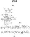
- FIG. 2is an exploded view illustrating a four-way switch according to one embodiment of the present invention.
- FIG. 3is a perspective view illustrating an enlarged portion of the four-way switch when a knob is tilted in a direction in which a stopper is formed, according to one embodiment of the present invention.
- FIG. 4is a transparent plan view illustrating positions where stoppers, guide protrusions, and guide groove portions of the four-way switch illustrated in FIG. 3 , are formed.
- a four-way switch 100includes a knob 101 that is tilted in four directions for performing four-way switching operations, and the four-way switch 100 includes a housing 110, stoppers 120, guide protrusions 130, and guide groove portions 140 having specific structures.
- the four-way switch 100may further include a mount 106, a rubber 105, an actuator 104, and a holder 103 mounted inside the housing 110 for performing switching operations, as illustrated in FIG. 2 . Further, a light guide 102 may be provided so that light can be output to the outside through the knob 101.
- the four-way switch 100includes the housing 110, the stoppers 120, the guide protrusions 130, and the guide groove portions 140 having specific structures, and is therefore capable of preventing two switches from operating simultaneously when pushing an edge portion of the knob of the four-way switch.
- the stopper 120is formed so as to protrude by a predetermined height.
- the stopper 120contacts a portion of the lower surface of the knob 101 during a tilting operation of the knob 101, to limit a downward motion of the knob 101.
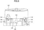
- the protruding height of the stopper 120is preferably the height at which the lower surface of the knob 101 contacts the upper surface of the stopper 120 when the knob 101 is tilted and the switching operation is performed.
- the height of a stopper 122may be further increased, and a recess portion 107, having a structure that engages with the stopper 122, may be provided on the lower surface of the knob 101.
- a round-shaped structure 121, 123 having a predetermined radiusmay be formed on the top surface of the stopper 120, 122.
- the downward motion of the knob 101is limited while the lower surface of the knob 101 and the upper surface of the stopper 120, 122 smoothly contact each other.
- the guide protrusions 130are formed by protruding a predetermined length.
- the guide groove portion 140is formed by protruding by a predetermined height so as to face the guide protrusion 130. More specifically, the inside of the guide groove portion 140 is provided with a recess portion 141 having a structure that engages with the guide protrusion 130.
- the guide protrusion 130has a predetermined width.
- the guide protrusion 130 and the guide groove portion 140interfere, thereby limiting downward motion of the knob 101.
- FIG. 4it is preferable that there are a total of four guide protrusions 130, each of which being disposed in one of the directions corresponding to the four directions in which the knob 101 performs the switching operation. More preferably, a round-shaped structure 131 having a predetermined radius is formed on the lower surface of the guide protrusion 130.
- the recess portion 141 provided in the guide groove portion 140preferably has a slit structure extending vertically by a predetermined length so that the guide protrusion 130 can engage with/separate from the guide groove portion 140, as illustrated in FIG. 6 .
- the four-way switch 100includes the housing 110, the stopper 120, 122, the guide protrusion 130, and the guide groove portion 140 having specific structures, thereby preventing two switches from operating simultaneously when pushing an edge portion of the knob of the four-way switch.
- the four-way switch 100 of the present inventionis provided with the stopper 120, which is formed by protruding by a predetermined height on one surface of the housing 110, and which contacts a portion of the lower surface of the knob 101 during the tilt motion of the knob 101, thereby limiting the downward motion of the knob 101. Accordingly, when the knob 101 is tilted in the direction of an edge portion that is not one of the four tilt directions for performing the switching operation, the downward motion of the knob 101 is limited, and as a result, it is possible to prevent two switches from operating simultaneously due to the tilt motion of the knob 101.
- the stopper 120is disposed at a specific position, and the stopper 120 is formed to protrude by a specific height, so that when the knob 101 is tilted in the direction of an edge portion that is not one of the four tilt directions for performing the switching operation, the downward motion of the knob 101 is effectively limited, and as a result, it is possible to prevent two switches from operating simultaneously due to the tilt motion of the knob 101.
- the guide protrusion 130 and the guide groove portion 140are disposed at specific positions, so that when the knob 101 is tilted in the direction of an edge portion that is not one of the four tilt directions for performing the switching operation, the downward motion of the knob 101 is effectively limited, and as a result, it is possible to prevent two switches from operating simultaneously due to the tilt motion of the knob 101.
- the four-way switch 100 of the present inventionby providing the guide protrusion 130 and the guide groove portion 140 having specific structures, when the knob 101 is pushed in one of the four tilt directions for performing the switching operation, the tilt motion of the knob 101 can be guided in the accurate direction in which the switch operates, and as a result, the operations of the four-way tilt switching can be accurately performed.
Landscapes
- Switches With Compound Operations (AREA)
Description
- The present invention relates to a four-way switch including a malfunction prevention structure, and more particularly to a four-way switch that solves the problem of two switches operating simultaneously when pushing an edge portion of the knob of the four-way switch, and the problem of not operating accurately in four directions.
FIG. 1 is a perspective view illustrating a conventional four-way switch.- In a four-way switch, there has been a problem that when an edge portion is pushed, two switches are simultaneously pushed and operated inadvertently. As a result, there has been a problem that it has not been possible to realize accurate switch operations performed by pushing the switch in four directions.
- In order to solve the above problem, as illustrated in
FIG. 1 , aprotrusion 13 is formed on the upper surface of ahousing 12 to prevent two switches from being pushed and operated when an edge portion of aknob 11 is pushed. - The
protrusion 13 is commonly referred to as a stopper. Theprotrusion 13 having such a structure limits the motion of theknob 11 when an edge portion of theknob 11 is pushed, until the switch reaches being on-stroke. - The size of the
protrusion 13 varies according to the size of a full-stroke. That is, the longer the full-stroke, the lower the height of theprotrusion 13. In a case where the height of theprotrusion 13 is low, when an edge portion of theknob 11 is pushed, theknob 11 is pushed down to on-stroke, and as a result, two switches are caused to operate, and the above problem cannot be resolved. - Accordingly, there is a need for a technique relating to a four-way switch that solves the problem of the conventional technology.
JP H08 222086 A EP 1 575 073 A1 shows a navigation key integrally formed with a panel in an electronic device comprises an outer key formed to have a resilient restoring force, and a holder for receiving the outer key, the holder being integrally mounted on the panel. The holder comprises a tact pressing member for directly pressing a tact switch disposed thereunder when the outer key is pressed down.GB 2 525 437 A - [Patent Document 1]
Korean Patent Publication No. 10-2004-0041760 (Publication date: May 20, 2004 - It is an object of the present invention to provide a four-way switch that includes a structure that solves the problem of two switches operating simultaneously when pushing an edge portion of the knob of the four-way switch, and the problem of not operating accurately in four directions.
- In order to achieve the above object, a four-way switch according to claim 1 forms an aspect of the present invention
- Furthermore, the predetermined height to which the stopper protrudes is a height at which the lower surface of the knob and an upper surface of the stopper contact each other, when the knob is tilted to perform the switching operation.
- According to an embodiment of the present invention, the lower surface of the knob is provided with a recess portion having a structure that engages with the stopper.
- According to an embodiment of the present invention, on an upper surface of the stopper, a round-shaped structure having a predetermined radius is formed.
- According to an embodiment of the present invention, the guide protrusion has a predetermined width, and when the knob is tilted in a direction in which the stopper is formed, the guide protrusion and the guide groove portion interfere, thereby limiting the downward motion of the knob.
- In this case, for example, the recess portion, which is provided in the guide groove portion, has a slit structure extending vertically by a predetermined length, such that the guide protrusion engages with and separates from the guide groove portion.
- According to an embodiment of the present invention, the guide protrusion includes a total of four guide protrusions, each of the four guide protrusions being disposed in a direction corresponding to one of the four directions in which the knob performs the switching operation.
- According to an embodiment of the present invention, on a lower surface of the guide protrusion, a round-shaped structure having a predetermined radius is formed.
- According to an embodiment of the present invention, the guide groove portion includes a total of four guide groove portions, each of the four guide groove portions being disposed in a direction corresponding to one of the four directions in which the knob performs the switching operation.
- As described above, according to the four-way switch of the present invention, a housing, a stopper, a guide protrusion, and a guide groove portion having a specific structure are provided, thereby preventing two switches from operating simultaneously when an edge portion of the knob of the four-way switch is pushed.
- Further, according to the four-way switch of the present invention, the stopper is formed on a surface of the housing so as to protrude by a predetermined height, the stopper being configured to limit a downward motion of the knob by contacting a portion of a lower surface of the knob when the knob is tilted, so that when the knob is tilted in the direction of an edge portion that is not one of the four tilt directions in which the switching operation is performed, the downward motion of the knob is limited, thereby preventing two switches from operating simultaneously by the tilt motion of the knob.
- Further, according to the four-way switch of the present invention, by disposing the stopper at a specific position, and forming the stopper so as to protrude by a specific height, when the knob is tilted in the direction of an edge portion that is not one of the four tilt directions in which the switching operation is performed, the downward motion of the knob is effectively limited, thereby preventing two switches from operating simultaneously by the tilt motion of the knob.
- Further, according to the four-way switch of the present invention, by disposing a guide protrusion and a guide groove portion at specific positions, when the knob is tilted in the direction of an edge portion that is not one of the four tilt directions in which the switching operation is performed, the downward motion of the knob is effectively limited, thereby preventing two switches from operating simultaneously by the tilt motion of the knob.
- Further, according to the four-way switch of the present invention, by providing a guide protrusion and a guide groove portion having a specific structure, when the knob is pushed in one of the four tilt directions in which the switching operation is performed, the tilt motion of the knob is guided in an accurate direction in which the switch operates, and as a result, the operations of the four-way tilt switching can be accurately realized.
FIG. 1 is a perspective view illustrating a four-way switch according to the conventional technology;FIG. 2 is an exploded view illustrating a four-way switch according to an embodiment of the present invention;FIG. 3 is an enlarged perspective view of a portion of a four-way switch according to an embodiment of the present invention;FIG. 4 is a transparent plan view illustrating positions at which the stoppers, the guide protrusions, and the guide groove portions of the four-way switch illustrated inFIG. 3 , are formed;FIG. 5 is a perspective view illustrating an operation in which the knob is tilted in a direction in which the stopper is formed; andFIG. 6 is a perspective view of the operation illustrated inFIG. 5 , viewed from the direction in which the guide projection is formed.- Hereinafter, embodiments of the present invention will be described in detail with reference to the accompanying drawings.
- Firstly, the terms used in the present specification and claims are to be interpreted not only as regular or dictionary meanings, but also as meanings commensurate with the technical ideas of the present invention.
- However, in the present specification, it is to be noted that when a member is provided "above" another member, this includes not only the case where the member is in contact with the other member, but also the case where yet another member is present between the aforementioned two members. Also, in the present specification, when a member is defined as "including" an element, unless stated to the contrary, this does not mean to exclude other elements, but includes a case where other elements are further included.
FIG. 2 is an exploded view illustrating a four-way switch according to one embodiment of the present invention.FIG. 3 is a perspective view illustrating an enlarged portion of the four-way switch when a knob is tilted in a direction in which a stopper is formed, according to one embodiment of the present invention.FIG. 4 is a transparent plan view illustrating positions where stoppers, guide protrusions, and guide groove portions of the four-way switch illustrated inFIG. 3 , are formed.- Referring to these drawings, a four-
way switch 100 according to the present embodiment includes aknob 101 that is tilted in four directions for performing four-way switching operations, and the four-way switch 100 includes ahousing 110,stoppers 120,guide protrusions 130, andguide groove portions 140 having specific structures. - The four-
way switch 100 according to the present embodiment may further include amount 106, arubber 105, anactuator 104, and aholder 103 mounted inside thehousing 110 for performing switching operations, as illustrated inFIG. 2 . Further, alight guide 102 may be provided so that light can be output to the outside through theknob 101. - The four-
way switch 100 according to the present embodiment including the above-described configuration includes thehousing 110, thestoppers 120, theguide protrusions 130, and theguide groove portions 140 having specific structures, and is therefore capable of preventing two switches from operating simultaneously when pushing an edge portion of the knob of the four-way switch. - Hereinafter, each configuration of the four-
way switch 100 according to the present embodiment will be described in detail with reference to the drawings. - As illustrated in
FIG. 3 , on one surface of the upper portion of thehousing 110, to which theknob 101 is attached in a manner as to be tiltable, thestopper 120 is formed so as to protrude by a predetermined height. - The
stopper 120 according to the present embodiment contacts a portion of the lower surface of theknob 101 during a tilting operation of theknob 101, to limit a downward motion of theknob 101. - According to the invention, there are a total of four
stoppers 120, each of which being disposed in a direction away by a predetermined angle from one of the four directions in which theknob 101 performs the switching operation, in a plan view. According to the invention, as illustrated inFIG. 4 , eachstopper 120 is disposed at a position forming an angle of θ = 45° relative to one of the four directions of theknob 101, centered on the tilt central axis C of theknob 101 in a plan view. - More specifically, as illustrated in
FIG. 5 , the protruding height of thestopper 120 is preferably the height at which the lower surface of theknob 101 contacts the upper surface of thestopper 120 when theknob 101 is tilted and the switching operation is performed. - Furthermore, as illustrated in
FIG. 6 , the height of astopper 122 may be further increased, and arecess portion 107, having a structure that engages with thestopper 122, may be provided on the lower surface of theknob 101. - In this case, as illustrated in
FIG. 6 , when theknob 101 is pushed in a tilt direction in which the switching operation is not performed, i.e., when an edge portion of theknob 101 is pushed, thestopper 122 and therecess portion 107 interfere, thereby limiting the tilt motion of theknob 101. As a result, the problem that the two switches operate simultaneously is fundamentally solved, by limiting tilt motion of theknob 101 in the wrong direction with thestopper 122 having a higher height and therecess portion 107 provided on the lower surface of theknob 101. - As illustrated in
FIGS. 3 and6 , a round-shapedstructure stopper - In this case, the downward motion of the
knob 101 is limited while the lower surface of theknob 101 and the upper surface of thestopper - On the lower surface of the
knob 101, theguide protrusions 130 are formed by protruding a predetermined length. - In this case, on one surface of the
housing 110, theguide groove portion 140 is formed by protruding by a predetermined height so as to face theguide protrusion 130. More specifically, the inside of theguide groove portion 140 is provided with arecess portion 141 having a structure that engages with theguide protrusion 130. - Specifically, the
guide protrusion 130 according to the present embodiment has a predetermined width. Here, as illustrated inFIG. 6 , when theknob 101 is tilted in the direction in which thestopper 120 is formed, theguide protrusion 130 and theguide groove portion 140 interfere, thereby limiting downward motion of theknob 101. - More specifically, as illustrated in
FIG. 4 , it is preferable that there are a total of fourguide protrusions 130, each of which being disposed in one of the directions corresponding to the four directions in which theknob 101 performs the switching operation. More preferably, a round-shapedstructure 131 having a predetermined radius is formed on the lower surface of theguide protrusion 130. - The
recess portion 141 provided in theguide groove portion 140 preferably has a slit structure extending vertically by a predetermined length so that theguide protrusion 130 can engage with/separate from theguide groove portion 140, as illustrated inFIG. 6 . - Preferably, there are a total of four
guide groove portions 140 according to the present embodiment, each of which being disposed in one of the four directions (up, down, left, right) of theknob 101 illustrated inFIG. 4 . - As described above, according to the four-
way switch 100 of the present invention, the four-way switch 100 includes thehousing 110, thestopper guide protrusion 130, and theguide groove portion 140 having specific structures, thereby preventing two switches from operating simultaneously when pushing an edge portion of the knob of the four-way switch. - Further, the four-
way switch 100 of the present invention is provided with thestopper 120, which is formed by protruding by a predetermined height on one surface of thehousing 110, and which contacts a portion of the lower surface of theknob 101 during the tilt motion of theknob 101, thereby limiting the downward motion of theknob 101. Accordingly, when theknob 101 is tilted in the direction of an edge portion that is not one of the four tilt directions for performing the switching operation, the downward motion of theknob 101 is limited, and as a result, it is possible to prevent two switches from operating simultaneously due to the tilt motion of theknob 101. - Further, according to the four-
way switch 100 of the present invention, thestopper 120 is disposed at a specific position, and thestopper 120 is formed to protrude by a specific height, so that when theknob 101 is tilted in the direction of an edge portion that is not one of the four tilt directions for performing the switching operation, the downward motion of theknob 101 is effectively limited, and as a result, it is possible to prevent two switches from operating simultaneously due to the tilt motion of theknob 101. - Further, according to the four-
way switch 100 of the present invention, theguide protrusion 130 and theguide groove portion 140 are disposed at specific positions, so that when theknob 101 is tilted in the direction of an edge portion that is not one of the four tilt directions for performing the switching operation, the downward motion of theknob 101 is effectively limited, and as a result, it is possible to prevent two switches from operating simultaneously due to the tilt motion of theknob 101. - Further, according to the four-
way switch 100 of the present invention, by providing theguide protrusion 130 and theguide groove portion 140 having specific structures, when theknob 101 is pushed in one of the four tilt directions for performing the switching operation, the tilt motion of theknob 101 can be guided in the accurate direction in which the switch operates, and as a result, the operations of the four-way tilt switching can be accurately performed. - Although the present invention has been described with reference to the embodiments described above, the present invention is not limited to the above-described embodiments, and various modifications can be made within the scope of the claims.
- 10
- conventional four-way switch
- 11
- knob
- 12
- housing
- 13
- protrusion
- C
- tilt central axis of knob
- 100
- four-way switch
- 101
- knob
- 102
- light guide
- 103
- holder
- 104
- actuator
- 105
- rubber
- 106
- mount
- 107
- recess portion
- 110
- housing
- 120
- stopper
- 121
- round-shaped structure
- 122
- stopper
- 123
- round-shaped structure
- 130
- guide protrusion
- 131
- round-shaped structure
- 140
- guide groove portion
- 141
- recess portion
Claims (9)
- A four-way switch (100) including a knob (101) configured to be tilted in four directions to perform a switching operation in the four directions, the four-way switch (100) comprising:a housing (110) to which the knob (101) is attached in a tiltable manner;a stopper (120) formed on a surface of the housing (110) so as to protrude by a predetermined height, the stopper (120) being configured to limit a downward motion of the knob (101) by contacting a portion of a lower surface of the knob (101) while the knob (101) is tilted;a guide protrusion (130) formed on the lower surface of the knob (101) so as to protrude by a predetermined length; anda guide groove portion (140) formed on the surface of the housing (110) so as to protrude by a predetermined height so as to face the guide protrusion (130), the guide groove portion (140) including a recess portion (141) having a structure that engages with the guide protrusion (130);characterized in thatthe stopper (120) includes a total of four stoppers (120), each of the four stoppers (120) being disposed in a direction away by a predetermined angle from one of the four directions in which the knob (101) performs the switching operation, in a plan view; andeach of the stoppers (120) is disposed at a position forming an angle of 45 degrees from one of the four directions of the knob (101), centered on a tilt central axis of the knob (101), in a plan view.
- The four-way switch (100) according to claim 1, wherein the predetermined height to which the stopper (120) protrudes is a height at which the lower surface of the knob (101) and an upper surface of the stopper (120) contact each other, when the knob (101) is tilted to perform the switching operation.
- The four-way switch (100) according to claim 1, wherein the lower surface of the knob (101) is provided with a recess portion (141) having a structure that engages with the stopper (120).
- The four-way switch (100) according to claim 1, wherein, on an upper surface of the stopper (120), a round-shaped structure (123) having a predetermined radius is formed.
- The four-way switch (100) according to claim 1, wherein the guide protrusion (130) has a predetermined width, and when the knob (101) is tilted in a direction in which the stopper (120) is formed, the guide protrusion (130) and the guide groove portion (140) interfere, thereby limiting the downward motion of the knob (101).
- The four-way switch (100) according to claim 5, wherein the recess portion (141), which is provided in the guide groove portion (140), has a slit structure extending vertically by a predetermined length, such that the guide protrusion (130) engages with and separates from the guide groove portion (140).
- The four-way switch (100) according to claim 1, wherein the guide protrusion (130) includes a total of four guide protrusions (130), each of the four guide protrusions (130) being disposed in a direction corresponding to one of the four directions in which the knob (101) performs the switching operation.
- The four-way switch (100) according to claim 1, wherein on a lower surface of the guide protrusion (130), a round-shaped structure (131) having a predetermined radius is formed.
- The four-way switch (100) according to claim 1, wherein the guide groove portion (140) includes a total of four guide groove portions (140), each of the four guide groove portions (140) being disposed in a direction corresponding to one of the four directions in which the knob (101) performs the switching operation.
Applications Claiming Priority (2)
| Application Number | Priority Date | Filing Date | Title |
|---|---|---|---|
| KR1020170017310AKR20180092042A (en) | 2017-02-08 | 2017-02-08 | 4 Way Switch Having Structure For Prevention of Wrong Operation |
| PCT/JP2017/043643WO2018146927A1 (en) | 2017-02-08 | 2017-12-05 | Four-way switch including malfunction prevention structure |
Publications (3)
| Publication Number | Publication Date |
|---|---|
| EP3582243A1 EP3582243A1 (en) | 2019-12-18 |
| EP3582243A4 EP3582243A4 (en) | 2020-12-02 |
| EP3582243B1true EP3582243B1 (en) | 2022-05-18 |
Family
ID=63107358
Family Applications (1)
| Application Number | Title | Priority Date | Filing Date |
|---|---|---|---|
| EP17896211.4AActiveEP3582243B1 (en) | 2017-02-08 | 2017-12-05 | Four-way switch including malfunction prevention structure |
Country Status (6)
| Country | Link |
|---|---|
| US (1) | US10950398B2 (en) |
| EP (1) | EP3582243B1 (en) |
| JP (1) | JP6757806B2 (en) |
| KR (2) | KR20180092042A (en) |
| CN (1) | CN110268497B (en) |
| WO (1) | WO2018146927A1 (en) |
Families Citing this family (2)
| Publication number | Priority date | Publication date | Assignee | Title |
|---|---|---|---|---|
| CN113867059A (en) | 2020-06-30 | 2021-12-31 | 京东方科技集团股份有限公司 | Liquid crystal display panel and liquid crystal display device |
| KR102750839B1 (en)* | 2022-11-09 | 2025-01-09 | 한국알프스 주식회사 | Operation guide module for multi way switch |
Family Cites Families (14)
| Publication number | Priority date | Publication date | Assignee | Title |
|---|---|---|---|---|
| JPS56114230A (en)* | 1980-02-13 | 1981-09-08 | Pioneer Electronic Corp | Mode selection switch |
| CA2101370C (en)* | 1992-07-31 | 1999-04-27 | Hiroshi Matsumiya | Control-key mechanism having improved operation feeling |
| JPH08222086A (en)* | 1995-02-17 | 1996-08-30 | Ichikoh Ind Ltd | Switch device |
| JP2000149718A (en)* | 1998-11-12 | 2000-05-30 | Nec Shizuoka Ltd | Multi-directional operation switch |
| JP3789733B2 (en)* | 2000-07-06 | 2006-06-28 | アルプス電気株式会社 | Compound operation switch |
| ES2192952B1 (en)* | 2001-08-24 | 2005-03-01 | Lear Automotive (Eeds) Spain, S.L. | MEMBRANE ELECTRIC SWITCH, WITH SEVEN CONTACT POSITIONS. |
| KR20040041760A (en) | 2002-11-11 | 2004-05-20 | 미츠쿠 덴시 고교 가부시키가이샤 | Four-way slide switch |
| US6657141B1 (en) | 2002-11-12 | 2003-12-02 | Mitsuku Denshi Kogyo K.K. | Four-way slide switch |
| KR100597008B1 (en)* | 2004-03-09 | 2006-07-06 | 삼성전자주식회사 | Electronic Keys |
| JP2007173098A (en)* | 2005-12-22 | 2007-07-05 | Alps Electric Co Ltd | Multidirectional switch device |
| JP6009908B2 (en)* | 2012-10-31 | 2016-10-19 | 株式会社ヴァレオジャパン | Multi-directional switch |
| GB2525437B (en)* | 2014-04-25 | 2016-05-25 | Cheng Uei Prec Ind Co Ltd | Push-button structure |
| JP6410357B2 (en)* | 2015-04-01 | 2018-10-24 | アルプス電気株式会社 | Input device |
| KR20170017310A (en) | 2015-08-06 | 2017-02-15 | 조의정 | Soap hanger |
- 2017
- 2017-02-08KRKR1020170017310Apatent/KR20180092042A/ennot_activeWithdrawn
- 2017-12-05JPJP2018566775Apatent/JP6757806B2/enactiveActive
- 2017-12-05KRKR1020197022682Apatent/KR102231233B1/enactiveActive
- 2017-12-05WOPCT/JP2017/043643patent/WO2018146927A1/ennot_activeCeased
- 2017-12-05CNCN201780086056.5Apatent/CN110268497B/enactiveActive
- 2017-12-05EPEP17896211.4Apatent/EP3582243B1/enactiveActive
- 2019
- 2019-07-30USUS16/526,154patent/US10950398B2/enactiveActive
Also Published As
| Publication number | Publication date |
|---|---|
| EP3582243A4 (en) | 2020-12-02 |
| US20190355532A1 (en) | 2019-11-21 |
| WO2018146927A1 (en) | 2018-08-16 |
| JPWO2018146927A1 (en) | 2019-06-27 |
| KR20190093697A (en) | 2019-08-09 |
| EP3582243A1 (en) | 2019-12-18 |
| CN110268497A (en) | 2019-09-20 |
| KR20180092042A (en) | 2018-08-17 |
| JP6757806B2 (en) | 2020-09-23 |
| KR102231233B1 (en) | 2021-03-24 |
| US10950398B2 (en) | 2021-03-16 |
| CN110268497B (en) | 2021-09-14 |
Similar Documents
| Publication | Publication Date | Title |
|---|---|---|
| US7288732B2 (en) | Multidirectional input device | |
| KR100800242B1 (en) | Slide Operated Switch | |
| US6399904B1 (en) | Multiple contact input device | |
| JP3951493B2 (en) | Multi-directional operation switch and composite switch using the same | |
| US10768658B2 (en) | Multi-directional input device | |
| EP2006868B1 (en) | Push button switch device with lever | |
| US6906269B2 (en) | Multi-directional slide switch | |
| EP3780052B1 (en) | Switch device | |
| EP3582243B1 (en) | Four-way switch including malfunction prevention structure | |
| EP2151840B1 (en) | Push-type switch device | |
| US6946606B2 (en) | Depression switch and multidirectional input device | |
| JP2003045291A (en) | Operation button structure | |
| US11527371B2 (en) | Push-button switch with lubricant retaining portion | |
| JP3937670B2 (en) | Multi-directional operation switch | |
| JP2022043622A (en) | Push switch | |
| JP2010153159A (en) | Multiple-direction slide type switch | |
| JP6204232B2 (en) | Input device | |
| JP2007200738A (en) | Push-button switch | |
| US6377756B1 (en) | Operation button used for portable apparatus | |
| JP2000339082A (en) | Multidirectional input device | |
| CN117441220A (en) | Press operating body and switch device | |
| WO2021220979A1 (en) | Switch | |
| JPH0741928U (en) | Multi-directional switch | |
| JP2020174025A (en) | Switch device | |
| JP3939098B2 (en) | Multi-directional operation switch |
Legal Events
| Date | Code | Title | Description |
|---|---|---|---|
| STAA | Information on the status of an ep patent application or granted ep patent | Free format text:STATUS: THE INTERNATIONAL PUBLICATION HAS BEEN MADE | |
| PUAI | Public reference made under article 153(3) epc to a published international application that has entered the european phase | Free format text:ORIGINAL CODE: 0009012 | |
| STAA | Information on the status of an ep patent application or granted ep patent | Free format text:STATUS: REQUEST FOR EXAMINATION WAS MADE | |
| 17P | Request for examination filed | Effective date:20190726 | |
| AK | Designated contracting states | Kind code of ref document:A1 Designated state(s):AL AT BE BG CH CY CZ DE DK EE ES FI FR GB GR HR HU IE IS IT LI LT LU LV MC MK MT NL NO PL PT RO RS SE SI SK SM TR | |
| AX | Request for extension of the european patent | Extension state:BA ME | |
| DAV | Request for validation of the european patent (deleted) | ||
| DAX | Request for extension of the european patent (deleted) | ||
| A4 | Supplementary search report drawn up and despatched | Effective date:20201030 | |
| RIC1 | Information provided on ipc code assigned before grant | Ipc:H01H 25/04 20060101AFI20201026BHEP | |
| GRAP | Despatch of communication of intention to grant a patent | Free format text:ORIGINAL CODE: EPIDOSNIGR1 | |
| STAA | Information on the status of an ep patent application or granted ep patent | Free format text:STATUS: GRANT OF PATENT IS INTENDED | |
| INTG | Intention to grant announced | Effective date:20210713 | |
| GRAJ | Information related to disapproval of communication of intention to grant by the applicant or resumption of examination proceedings by the epo deleted | Free format text:ORIGINAL CODE: EPIDOSDIGR1 | |
| STAA | Information on the status of an ep patent application or granted ep patent | Free format text:STATUS: REQUEST FOR EXAMINATION WAS MADE | |
| GRAP | Despatch of communication of intention to grant a patent | Free format text:ORIGINAL CODE: EPIDOSNIGR1 | |
| STAA | Information on the status of an ep patent application or granted ep patent | Free format text:STATUS: GRANT OF PATENT IS INTENDED | |
| INTC | Intention to grant announced (deleted) | ||
| INTG | Intention to grant announced | Effective date:20211209 | |
| GRAS | Grant fee paid | Free format text:ORIGINAL CODE: EPIDOSNIGR3 | |
| GRAA | (expected) grant | Free format text:ORIGINAL CODE: 0009210 | |
| STAA | Information on the status of an ep patent application or granted ep patent | Free format text:STATUS: THE PATENT HAS BEEN GRANTED | |
| AK | Designated contracting states | Kind code of ref document:B1 Designated state(s):AL AT BE BG CH CY CZ DE DK EE ES FI FR GB GR HR HU IE IS IT LI LT LU LV MC MK MT NL NO PL PT RO RS SE SI SK SM TR | |
| REG | Reference to a national code | Ref country code:GB Ref legal event code:FG4D | |
| REG | Reference to a national code | Ref country code:CH Ref legal event code:EP | |
| REG | Reference to a national code | Ref country code:IE Ref legal event code:FG4D | |
| REG | Reference to a national code | Ref country code:DE Ref legal event code:R096 Ref document number:602017057746 Country of ref document:DE | |
| REG | Reference to a national code | Ref country code:AT Ref legal event code:REF Ref document number:1493621 Country of ref document:AT Kind code of ref document:T Effective date:20220615 | |
| REG | Reference to a national code | Ref country code:LT Ref legal event code:MG9D | |
| REG | Reference to a national code | Ref country code:NL Ref legal event code:MP Effective date:20220518 | |
| REG | Reference to a national code | Ref country code:AT Ref legal event code:MK05 Ref document number:1493621 Country of ref document:AT Kind code of ref document:T Effective date:20220518 | |
| PG25 | Lapsed in a contracting state [announced via postgrant information from national office to epo] | Ref country code:SE Free format text:LAPSE BECAUSE OF FAILURE TO SUBMIT A TRANSLATION OF THE DESCRIPTION OR TO PAY THE FEE WITHIN THE PRESCRIBED TIME-LIMIT Effective date:20220518 Ref country code:PT Free format text:LAPSE BECAUSE OF FAILURE TO SUBMIT A TRANSLATION OF THE DESCRIPTION OR TO PAY THE FEE WITHIN THE PRESCRIBED TIME-LIMIT Effective date:20220919 Ref country code:NO Free format text:LAPSE BECAUSE OF FAILURE TO SUBMIT A TRANSLATION OF THE DESCRIPTION OR TO PAY THE FEE WITHIN THE PRESCRIBED TIME-LIMIT Effective date:20220818 Ref country code:NL Free format text:LAPSE BECAUSE OF FAILURE TO SUBMIT A TRANSLATION OF THE DESCRIPTION OR TO PAY THE FEE WITHIN THE PRESCRIBED TIME-LIMIT Effective date:20220518 Ref country code:LT Free format text:LAPSE BECAUSE OF FAILURE TO SUBMIT A TRANSLATION OF THE DESCRIPTION OR TO PAY THE FEE WITHIN THE PRESCRIBED TIME-LIMIT Effective date:20220518 Ref country code:HR Free format text:LAPSE BECAUSE OF FAILURE TO SUBMIT A TRANSLATION OF THE DESCRIPTION OR TO PAY THE FEE WITHIN THE PRESCRIBED TIME-LIMIT Effective date:20220518 Ref country code:GR Free format text:LAPSE BECAUSE OF FAILURE TO SUBMIT A TRANSLATION OF THE DESCRIPTION OR TO PAY THE FEE WITHIN THE PRESCRIBED TIME-LIMIT Effective date:20220819 Ref country code:FI Free format text:LAPSE BECAUSE OF FAILURE TO SUBMIT A TRANSLATION OF THE DESCRIPTION OR TO PAY THE FEE WITHIN THE PRESCRIBED TIME-LIMIT Effective date:20220518 Ref country code:ES Free format text:LAPSE BECAUSE OF FAILURE TO SUBMIT A TRANSLATION OF THE DESCRIPTION OR TO PAY THE FEE WITHIN THE PRESCRIBED TIME-LIMIT Effective date:20220518 Ref country code:BG Free format text:LAPSE BECAUSE OF FAILURE TO SUBMIT A TRANSLATION OF THE DESCRIPTION OR TO PAY THE FEE WITHIN THE PRESCRIBED TIME-LIMIT Effective date:20220818 Ref country code:AT Free format text:LAPSE BECAUSE OF FAILURE TO SUBMIT A TRANSLATION OF THE DESCRIPTION OR TO PAY THE FEE WITHIN THE PRESCRIBED TIME-LIMIT Effective date:20220518 | |
| PG25 | Lapsed in a contracting state [announced via postgrant information from national office to epo] | Ref country code:RS Free format text:LAPSE BECAUSE OF FAILURE TO SUBMIT A TRANSLATION OF THE DESCRIPTION OR TO PAY THE FEE WITHIN THE PRESCRIBED TIME-LIMIT Effective date:20220518 Ref country code:PL Free format text:LAPSE BECAUSE OF FAILURE TO SUBMIT A TRANSLATION OF THE DESCRIPTION OR TO PAY THE FEE WITHIN THE PRESCRIBED TIME-LIMIT Effective date:20220518 Ref country code:LV Free format text:LAPSE BECAUSE OF FAILURE TO SUBMIT A TRANSLATION OF THE DESCRIPTION OR TO PAY THE FEE WITHIN THE PRESCRIBED TIME-LIMIT Effective date:20220518 Ref country code:IS Free format text:LAPSE BECAUSE OF FAILURE TO SUBMIT A TRANSLATION OF THE DESCRIPTION OR TO PAY THE FEE WITHIN THE PRESCRIBED TIME-LIMIT Effective date:20220918 | |
| PG25 | Lapsed in a contracting state [announced via postgrant information from national office to epo] | Ref country code:SM Free format text:LAPSE BECAUSE OF FAILURE TO SUBMIT A TRANSLATION OF THE DESCRIPTION OR TO PAY THE FEE WITHIN THE PRESCRIBED TIME-LIMIT Effective date:20220518 Ref country code:SK Free format text:LAPSE BECAUSE OF FAILURE TO SUBMIT A TRANSLATION OF THE DESCRIPTION OR TO PAY THE FEE WITHIN THE PRESCRIBED TIME-LIMIT Effective date:20220518 Ref country code:RO Free format text:LAPSE BECAUSE OF FAILURE TO SUBMIT A TRANSLATION OF THE DESCRIPTION OR TO PAY THE FEE WITHIN THE PRESCRIBED TIME-LIMIT Effective date:20220518 Ref country code:EE Free format text:LAPSE BECAUSE OF FAILURE TO SUBMIT A TRANSLATION OF THE DESCRIPTION OR TO PAY THE FEE WITHIN THE PRESCRIBED TIME-LIMIT Effective date:20220518 Ref country code:DK Free format text:LAPSE BECAUSE OF FAILURE TO SUBMIT A TRANSLATION OF THE DESCRIPTION OR TO PAY THE FEE WITHIN THE PRESCRIBED TIME-LIMIT Effective date:20220518 Ref country code:CZ Free format text:LAPSE BECAUSE OF FAILURE TO SUBMIT A TRANSLATION OF THE DESCRIPTION OR TO PAY THE FEE WITHIN THE PRESCRIBED TIME-LIMIT Effective date:20220518 | |
| REG | Reference to a national code | Ref country code:DE Ref legal event code:R097 Ref document number:602017057746 Country of ref document:DE | |
| PLBE | No opposition filed within time limit | Free format text:ORIGINAL CODE: 0009261 | |
| STAA | Information on the status of an ep patent application or granted ep patent | Free format text:STATUS: NO OPPOSITION FILED WITHIN TIME LIMIT | |
| PG25 | Lapsed in a contracting state [announced via postgrant information from national office to epo] | Ref country code:AL Free format text:LAPSE BECAUSE OF FAILURE TO SUBMIT A TRANSLATION OF THE DESCRIPTION OR TO PAY THE FEE WITHIN THE PRESCRIBED TIME-LIMIT Effective date:20220518 | |
| 26N | No opposition filed | Effective date:20230221 | |
| PG25 | Lapsed in a contracting state [announced via postgrant information from national office to epo] | Ref country code:SI Free format text:LAPSE BECAUSE OF FAILURE TO SUBMIT A TRANSLATION OF THE DESCRIPTION OR TO PAY THE FEE WITHIN THE PRESCRIBED TIME-LIMIT Effective date:20220518 | |
| REG | Reference to a national code | Ref country code:CH Ref legal event code:PL | |
| GBPC | Gb: european patent ceased through non-payment of renewal fee | Effective date:20221205 | |
| REG | Reference to a national code | Ref country code:BE Ref legal event code:MM Effective date:20221231 | |
| PG25 | Lapsed in a contracting state [announced via postgrant information from national office to epo] | Ref country code:LU Free format text:LAPSE BECAUSE OF NON-PAYMENT OF DUE FEES Effective date:20221205 | |
| PG25 | Lapsed in a contracting state [announced via postgrant information from national office to epo] | Ref country code:LI Free format text:LAPSE BECAUSE OF NON-PAYMENT OF DUE FEES Effective date:20221231 Ref country code:IE Free format text:LAPSE BECAUSE OF NON-PAYMENT OF DUE FEES Effective date:20221205 Ref country code:GB Free format text:LAPSE BECAUSE OF NON-PAYMENT OF DUE FEES Effective date:20221205 Ref country code:CH Free format text:LAPSE BECAUSE OF NON-PAYMENT OF DUE FEES Effective date:20221231 | |
| PG25 | Lapsed in a contracting state [announced via postgrant information from national office to epo] | Ref country code:FR Free format text:LAPSE BECAUSE OF NON-PAYMENT OF DUE FEES Effective date:20221231 Ref country code:BE Free format text:LAPSE BECAUSE OF NON-PAYMENT OF DUE FEES Effective date:20221231 | |
| PG25 | Lapsed in a contracting state [announced via postgrant information from national office to epo] | Ref country code:IT Free format text:LAPSE BECAUSE OF FAILURE TO SUBMIT A TRANSLATION OF THE DESCRIPTION OR TO PAY THE FEE WITHIN THE PRESCRIBED TIME-LIMIT Effective date:20220518 | |
| PG25 | Lapsed in a contracting state [announced via postgrant information from national office to epo] | Ref country code:HU Free format text:LAPSE BECAUSE OF FAILURE TO SUBMIT A TRANSLATION OF THE DESCRIPTION OR TO PAY THE FEE WITHIN THE PRESCRIBED TIME-LIMIT; INVALID AB INITIO Effective date:20171205 | |
| PG25 | Lapsed in a contracting state [announced via postgrant information from national office to epo] | Ref country code:CY Free format text:LAPSE BECAUSE OF FAILURE TO SUBMIT A TRANSLATION OF THE DESCRIPTION OR TO PAY THE FEE WITHIN THE PRESCRIBED TIME-LIMIT Effective date:20220511 | |
| PG25 | Lapsed in a contracting state [announced via postgrant information from national office to epo] | Ref country code:MK Free format text:LAPSE BECAUSE OF FAILURE TO SUBMIT A TRANSLATION OF THE DESCRIPTION OR TO PAY THE FEE WITHIN THE PRESCRIBED TIME-LIMIT Effective date:20220511 | |
| PG25 | Lapsed in a contracting state [announced via postgrant information from national office to epo] | Ref country code:MC Free format text:LAPSE BECAUSE OF FAILURE TO SUBMIT A TRANSLATION OF THE DESCRIPTION OR TO PAY THE FEE WITHIN THE PRESCRIBED TIME-LIMIT Effective date:20220518 | |
| PG25 | Lapsed in a contracting state [announced via postgrant information from national office to epo] | Ref country code:TR Free format text:LAPSE BECAUSE OF FAILURE TO SUBMIT A TRANSLATION OF THE DESCRIPTION OR TO PAY THE FEE WITHIN THE PRESCRIBED TIME-LIMIT Effective date:20220511 Ref country code:MC Free format text:LAPSE BECAUSE OF FAILURE TO SUBMIT A TRANSLATION OF THE DESCRIPTION OR TO PAY THE FEE WITHIN THE PRESCRIBED TIME-LIMIT Effective date:20220518 | |
| PG25 | Lapsed in a contracting state [announced via postgrant information from national office to epo] | Ref country code:MT Free format text:LAPSE BECAUSE OF FAILURE TO SUBMIT A TRANSLATION OF THE DESCRIPTION OR TO PAY THE FEE WITHIN THE PRESCRIBED TIME-LIMIT Effective date:20220511 | |
| PG25 | Lapsed in a contracting state [announced via postgrant information from national office to epo] | Ref country code:BG Free format text:LAPSE BECAUSE OF FAILURE TO SUBMIT A TRANSLATION OF THE DESCRIPTION OR TO PAY THE FEE WITHIN THE PRESCRIBED TIME-LIMIT Effective date:20220518 | |
| PG25 | Lapsed in a contracting state [announced via postgrant information from national office to epo] | Ref country code:BG Free format text:LAPSE BECAUSE OF FAILURE TO SUBMIT A TRANSLATION OF THE DESCRIPTION OR TO PAY THE FEE WITHIN THE PRESCRIBED TIME-LIMIT Effective date:20220518 | |
| PGFP | Annual fee paid to national office [announced via postgrant information from national office to epo] | Ref country code:DE Payment date:20241210 Year of fee payment:8 |