EP3572758B1 - Microchannel heat exchangers for gas turbine intercooling and condensing - Google Patents
Microchannel heat exchangers for gas turbine intercooling and condensingDownload PDFInfo
- Publication number
- EP3572758B1 EP3572758B1EP19178904.9AEP19178904AEP3572758B1EP 3572758 B1EP3572758 B1EP 3572758B1EP 19178904 AEP19178904 AEP 19178904AEP 3572758 B1EP3572758 B1EP 3572758B1
- Authority
- EP
- European Patent Office
- Prior art keywords
- mchx
- air
- working fluid
- layer
- passage
- Prior art date
- Legal status (The legal status is an assumption and is not a legal conclusion. Google has not performed a legal analysis and makes no representation as to the accuracy of the status listed.)
- Active
Links
Images


Classifications
- F—MECHANICAL ENGINEERING; LIGHTING; HEATING; WEAPONS; BLASTING
- F02—COMBUSTION ENGINES; HOT-GAS OR COMBUSTION-PRODUCT ENGINE PLANTS
- F02C—GAS-TURBINE PLANTS; AIR INTAKES FOR JET-PROPULSION PLANTS; CONTROLLING FUEL SUPPLY IN AIR-BREATHING JET-PROPULSION PLANTS
- F02C7/00—Features, components parts, details or accessories, not provided for in, or of interest apart form groups F02C1/00 - F02C6/00; Air intakes for jet-propulsion plants
- F02C7/12—Cooling of plants
- F02C7/16—Cooling of plants characterised by cooling medium
- F02C7/18—Cooling of plants characterised by cooling medium the medium being gaseous, e.g. air
- F—MECHANICAL ENGINEERING; LIGHTING; HEATING; WEAPONS; BLASTING
- F02—COMBUSTION ENGINES; HOT-GAS OR COMBUSTION-PRODUCT ENGINE PLANTS
- F02C—GAS-TURBINE PLANTS; AIR INTAKES FOR JET-PROPULSION PLANTS; CONTROLLING FUEL SUPPLY IN AIR-BREATHING JET-PROPULSION PLANTS
- F02C7/00—Features, components parts, details or accessories, not provided for in, or of interest apart form groups F02C1/00 - F02C6/00; Air intakes for jet-propulsion plants
- F02C7/12—Cooling of plants
- F02C7/14—Cooling of plants of fluids in the plant, e.g. lubricant or fuel
- F02C7/141—Cooling of plants of fluids in the plant, e.g. lubricant or fuel of working fluid
- F02C7/143—Cooling of plants of fluids in the plant, e.g. lubricant or fuel of working fluid before or between the compressor stages
- F—MECHANICAL ENGINEERING; LIGHTING; HEATING; WEAPONS; BLASTING
- F02—COMBUSTION ENGINES; HOT-GAS OR COMBUSTION-PRODUCT ENGINE PLANTS
- F02K—JET-PROPULSION PLANTS
- F02K3/00—Plants including a gas turbine driving a compressor or a ducted fan
- F02K3/08—Plants including a gas turbine driving a compressor or a ducted fan with supplementary heating of the working fluid; Control thereof
- F02K3/105—Heating the by-pass flow
- F02K3/115—Heating the by-pass flow by means of indirect heat exchange
- F—MECHANICAL ENGINEERING; LIGHTING; HEATING; WEAPONS; BLASTING
- F28—HEAT EXCHANGE IN GENERAL
- F28D—HEAT-EXCHANGE APPARATUS, NOT PROVIDED FOR IN ANOTHER SUBCLASS, IN WHICH THE HEAT-EXCHANGE MEDIA DO NOT COME INTO DIRECT CONTACT
- F28D9/00—Heat-exchange apparatus having stationary plate-like or laminated conduit assemblies for both heat-exchange media, the media being in contact with different sides of a conduit wall
- F28D9/0012—Heat-exchange apparatus having stationary plate-like or laminated conduit assemblies for both heat-exchange media, the media being in contact with different sides of a conduit wall the apparatus having an annular form
- F—MECHANICAL ENGINEERING; LIGHTING; HEATING; WEAPONS; BLASTING
- F28—HEAT EXCHANGE IN GENERAL
- F28D—HEAT-EXCHANGE APPARATUS, NOT PROVIDED FOR IN ANOTHER SUBCLASS, IN WHICH THE HEAT-EXCHANGE MEDIA DO NOT COME INTO DIRECT CONTACT
- F28D9/00—Heat-exchange apparatus having stationary plate-like or laminated conduit assemblies for both heat-exchange media, the media being in contact with different sides of a conduit wall
- F28D9/0031—Heat-exchange apparatus having stationary plate-like or laminated conduit assemblies for both heat-exchange media, the media being in contact with different sides of a conduit wall the conduits for one heat-exchange medium being formed by paired plates touching each other
- F28D9/0037—Heat-exchange apparatus having stationary plate-like or laminated conduit assemblies for both heat-exchange media, the media being in contact with different sides of a conduit wall the conduits for one heat-exchange medium being formed by paired plates touching each other the conduits for the other heat-exchange medium also being formed by paired plates touching each other
- F—MECHANICAL ENGINEERING; LIGHTING; HEATING; WEAPONS; BLASTING
- F28—HEAT EXCHANGE IN GENERAL
- F28F—DETAILS OF HEAT-EXCHANGE AND HEAT-TRANSFER APPARATUS, OF GENERAL APPLICATION
- F28F3/00—Plate-like or laminated elements; Assemblies of plate-like or laminated elements
- F28F3/02—Elements or assemblies thereof with means for increasing heat-transfer area, e.g. with fins, with recesses, with corrugations
- F28F3/04—Elements or assemblies thereof with means for increasing heat-transfer area, e.g. with fins, with recesses, with corrugations the means being integral with the element
- F28F3/048—Elements or assemblies thereof with means for increasing heat-transfer area, e.g. with fins, with recesses, with corrugations the means being integral with the element in the form of ribs integral with the element or local variations in thickness of the element, e.g. grooves, microchannels
- F—MECHANICAL ENGINEERING; LIGHTING; HEATING; WEAPONS; BLASTING
- F28—HEAT EXCHANGE IN GENERAL
- F28F—DETAILS OF HEAT-EXCHANGE AND HEAT-TRANSFER APPARATUS, OF GENERAL APPLICATION
- F28F9/00—Casings; Header boxes; Auxiliary supports for elements; Auxiliary members within casings
- F28F9/02—Header boxes; End plates
- F28F9/026—Header boxes; End plates with static flow control means, e.g. with means for uniformly distributing heat exchange media into conduits
- F—MECHANICAL ENGINEERING; LIGHTING; HEATING; WEAPONS; BLASTING
- F02—COMBUSTION ENGINES; HOT-GAS OR COMBUSTION-PRODUCT ENGINE PLANTS
- F02C—GAS-TURBINE PLANTS; AIR INTAKES FOR JET-PROPULSION PLANTS; CONTROLLING FUEL SUPPLY IN AIR-BREATHING JET-PROPULSION PLANTS
- F02C3/00—Gas-turbine plants characterised by the use of combustion products as the working fluid
- F02C3/04—Gas-turbine plants characterised by the use of combustion products as the working fluid having a turbine driving a compressor
- F—MECHANICAL ENGINEERING; LIGHTING; HEATING; WEAPONS; BLASTING
- F05—INDEXING SCHEMES RELATING TO ENGINES OR PUMPS IN VARIOUS SUBCLASSES OF CLASSES F01-F04
- F05D—INDEXING SCHEME FOR ASPECTS RELATING TO NON-POSITIVE-DISPLACEMENT MACHINES OR ENGINES, GAS-TURBINES OR JET-PROPULSION PLANTS
- F05D2210/00—Working fluids
- F05D2210/10—Kind or type
- F05D2210/13—Kind or type mixed, e.g. two-phase fluid
- F—MECHANICAL ENGINEERING; LIGHTING; HEATING; WEAPONS; BLASTING
- F05—INDEXING SCHEMES RELATING TO ENGINES OR PUMPS IN VARIOUS SUBCLASSES OF CLASSES F01-F04
- F05D—INDEXING SCHEME FOR ASPECTS RELATING TO NON-POSITIVE-DISPLACEMENT MACHINES OR ENGINES, GAS-TURBINES OR JET-PROPULSION PLANTS
- F05D2220/00—Application
- F05D2220/60—Application making use of surplus or waste energy
- F05D2220/62—Application making use of surplus or waste energy with energy recovery turbines
- F—MECHANICAL ENGINEERING; LIGHTING; HEATING; WEAPONS; BLASTING
- F05—INDEXING SCHEMES RELATING TO ENGINES OR PUMPS IN VARIOUS SUBCLASSES OF CLASSES F01-F04
- F05D—INDEXING SCHEME FOR ASPECTS RELATING TO NON-POSITIVE-DISPLACEMENT MACHINES OR ENGINES, GAS-TURBINES OR JET-PROPULSION PLANTS
- F05D2220/00—Application
- F05D2220/70—Application in combination with
- F05D2220/72—Application in combination with a steam turbine
- F—MECHANICAL ENGINEERING; LIGHTING; HEATING; WEAPONS; BLASTING
- F05—INDEXING SCHEMES RELATING TO ENGINES OR PUMPS IN VARIOUS SUBCLASSES OF CLASSES F01-F04
- F05D—INDEXING SCHEME FOR ASPECTS RELATING TO NON-POSITIVE-DISPLACEMENT MACHINES OR ENGINES, GAS-TURBINES OR JET-PROPULSION PLANTS
- F05D2230/00—Manufacture
- F05D2230/10—Manufacture by removing material
- F05D2230/11—Manufacture by removing material by electrochemical methods
- F—MECHANICAL ENGINEERING; LIGHTING; HEATING; WEAPONS; BLASTING
- F05—INDEXING SCHEMES RELATING TO ENGINES OR PUMPS IN VARIOUS SUBCLASSES OF CLASSES F01-F04
- F05D—INDEXING SCHEME FOR ASPECTS RELATING TO NON-POSITIVE-DISPLACEMENT MACHINES OR ENGINES, GAS-TURBINES OR JET-PROPULSION PLANTS
- F05D2260/00—Function
- F05D2260/20—Heat transfer, e.g. cooling
- F05D2260/204—Heat transfer, e.g. cooling by the use of microcircuits
- F—MECHANICAL ENGINEERING; LIGHTING; HEATING; WEAPONS; BLASTING
- F05—INDEXING SCHEMES RELATING TO ENGINES OR PUMPS IN VARIOUS SUBCLASSES OF CLASSES F01-F04
- F05D—INDEXING SCHEME FOR ASPECTS RELATING TO NON-POSITIVE-DISPLACEMENT MACHINES OR ENGINES, GAS-TURBINES OR JET-PROPULSION PLANTS
- F05D2260/00—Function
- F05D2260/20—Heat transfer, e.g. cooling
- F05D2260/205—Cooling fluid recirculation, i.e. after cooling one or more components is the cooling fluid recovered and used elsewhere for other purposes
- F—MECHANICAL ENGINEERING; LIGHTING; HEATING; WEAPONS; BLASTING
- F05—INDEXING SCHEMES RELATING TO ENGINES OR PUMPS IN VARIOUS SUBCLASSES OF CLASSES F01-F04
- F05D—INDEXING SCHEME FOR ASPECTS RELATING TO NON-POSITIVE-DISPLACEMENT MACHINES OR ENGINES, GAS-TURBINES OR JET-PROPULSION PLANTS
- F05D2260/00—Function
- F05D2260/20—Heat transfer, e.g. cooling
- F05D2260/207—Heat transfer, e.g. cooling using a phase changing mass, e.g. heat absorbing by melting or boiling
- F—MECHANICAL ENGINEERING; LIGHTING; HEATING; WEAPONS; BLASTING
- F28—HEAT EXCHANGE IN GENERAL
- F28D—HEAT-EXCHANGE APPARATUS, NOT PROVIDED FOR IN ANOTHER SUBCLASS, IN WHICH THE HEAT-EXCHANGE MEDIA DO NOT COME INTO DIRECT CONTACT
- F28D21/00—Heat-exchange apparatus not covered by any of the groups F28D1/00 - F28D20/00
- F28D2021/0019—Other heat exchangers for particular applications; Heat exchange systems not otherwise provided for
- F28D2021/0026—Other heat exchangers for particular applications; Heat exchange systems not otherwise provided for for combustion engines, e.g. for gas turbines or for Stirling engines
- F—MECHANICAL ENGINEERING; LIGHTING; HEATING; WEAPONS; BLASTING
- F28—HEAT EXCHANGE IN GENERAL
- F28F—DETAILS OF HEAT-EXCHANGE AND HEAT-TRANSFER APPARATUS, OF GENERAL APPLICATION
- F28F2260/00—Heat exchangers or heat exchange elements having special size, e.g. microstructures
- F—MECHANICAL ENGINEERING; LIGHTING; HEATING; WEAPONS; BLASTING
- F28—HEAT EXCHANGE IN GENERAL
- F28F—DETAILS OF HEAT-EXCHANGE AND HEAT-TRANSFER APPARATUS, OF GENERAL APPLICATION
- F28F2275/00—Fastening; Joining
- F—MECHANICAL ENGINEERING; LIGHTING; HEATING; WEAPONS; BLASTING
- F28—HEAT EXCHANGE IN GENERAL
- F28F—DETAILS OF HEAT-EXCHANGE AND HEAT-TRANSFER APPARATUS, OF GENERAL APPLICATION
- F28F2275/00—Fastening; Joining
- F28F2275/06—Fastening; Joining by welding
- F28F2275/061—Fastening; Joining by welding by diffusion bonding
Definitions
- An improved heat exchanger for use in a gas turbine engineis disclosed.
- Heat exchangersmay be employed in the gas turbine engine sector (e.g., the aerospace sector) for the purpose of transferring heat between a core air stream and a bypass stream.
- gas turbine engine sectore.g., the aerospace sector
- air to air type heat exchangersare employed for this purpose.
- These types of heat exchangershowever can require complex ducting, which adds system weight, costs, and can reduce their effectiveness.
- Further prior artis disclosed in US2010314088A1 , EP2412631A2 , US2011146226A1 , and US2007298486A1 . Accordingly, there is room for further improvements in this area.
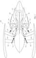
- Figure 1illustrates an exemplary gas turbine engine 100, which includes a fan 102, a vane/strut 104, a core stream diffuser 106, an intercooler-type microchannel heat exchanger (MCHX) 108, a high pressure compressor nozzle 110, and a closed cycle turbine 112. Ambient air enters past the fan 102 and is directed past the core stream diffuser 106 as a core air stream 114 that proceeds through the intercooler-type MCHX 108 where it is cooled.
- MCHXmicrochannel heat exchanger
- the gas turbine engine 100also includes a bypass stream diffuser 116, a condenser-type MCHX 118, and an exit nozzle 120.
- Fan stream air in the form of a bypass air stream 122proceeds past the bypass stream diffuser 116 to the condenser-type MCHX 118, and passes through the condenser-type MCHX 118 where the bypass air stream 122 is heated before exiting the exit nozzle 120.
- a working fluid(not shown) that passes through the intercooler-type MCHX 108 of Figure 1 also passes through the condenser-type MCHX 118.
- the core air stream 114heats the working fluid in the intercooler-type MCHX 108 (i.e., heat is transferred from the core air stream 114 to the working fluid in the intercooler-type MCHX 108) while the bypass air stream 122 cools the working fluid in the condenser-type MCHX 118 (i.e., heat is transferred from the working fluid in the condenser-type MCHX 118 to the bypass air stream 122).
- intercooler-type MCHX 108and the condenser-type MCHX 118 will be set forth below with respect to Figures 2-7 .
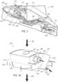
- FIG. 2a detailed view 200 of a portion of gas turbine engine 100 of Figure 1 employing a microchannel heat exchange system is shown according to an embodiment.
- the portions of the gas turbine engine 100 shown in both Figures 1 and 2include the intercooler-type MCHX 108, the closed cycle turbine 112 , the condenser-type MCHX 118, the core stream diffuser 106, and the bypass stream diffuser 116.
- Figure 2also depicts an accumulator/separator 202, a liquid working fluid pump 204, and a series of working fluid piping 206.
- a core air stream 208passes through the core stream diffuser 106 and through the intercooler-type MCHX 108.
- a working fluid(not shown) therein changes phase from a liquid to a gas as heat from the core air stream 208 is transferred to the working fluid in the intercooler-type MCHX 108.
- the working fluidinstead changes from a liquid to a supercritical fluid.
- the working fluidafter passing through the intercooler-type MCHX 108 the working fluid then passes via the series of working fluid piping 206 as a high pressure gas or supercritical fluid to the closed cycle turbine 112 thus generating power.
- the working fluidis then conveyed via the series of working fluid piping 206 as a low pressure gas or gas and liquid mixture to the condenser-type MCHX 118.
- the condenser-type MCHX 118causes the working fluid therein to change phase once again, this time from a gas to a liquid by transferring heat from the working fluid to a bypass air stream 210 that passes through the condenser-type MCHX 118 via the bypass stream diffuser 116.
- the working fluidAfter the working fluid passes through the condenser-type MCHX 118, the working fluid is then conveyed via the series of working fluid piping 206 as a liquid to the accumulator/separator 202, then to the liquid pump 204, and then again to the intercooler-type MCHX 108.
- piping configurations different than the configuration of the series of working fluid piping 206 shown in Figure 2may be employed to couple together two MCHXs such as intercooler-type MCHX 108 and condenser-type MCHX 118.
- the MCHX 300includes an inlet 304 on a front side 306 and an outlet 308 also on the front side 306. It is noted, that according to other embodiments, the outlet may be on a back side 310 rather than the front side 306. Alternatively, the outlet 308 may remain on the front side 306, while the inlet 304 is instead positioned on the back side 310. Indeed, according to embodiments, the outlet 308 and inlet 304 may be on any side of the MCHX 300.
- the MCHX 300have an external intake manifold 312 and an external outtake manifold 314, where each is shown in phantom.
- the MCHX 300also includes a top side 316 and a bottom side 318.
- the exaggerated view 302 of Figure 3bis of region A on the top side 316 of the MCHX 300 shown in Figure 3a .
- the top side 316includes a plurality of air-passage channels 320.
- These air-passage channels 320extend through the MCHX 300 from the top side 316 to the bottom side 318.
- the air-passage channels 320are configured to allow air 322 to pass through the MCHX 300. That is, the air-passage channels 320 are configured to allow air 322 to enter the top side 316 of the MCHX 300 and exit through the bottom side 318 of the MCHX 300. Further information regarding the plurality of air-passage channels 320 will be set forth in detail below with respect to Figures 4 and 7a-b .
- the exaggerated view 302 of Figure 3balso illustrates that the MCHX 300 is comprised of a plurality of layers.
- the layersinclude a plurality of working fluid layers 324, a plurality of sealing layers 326, and a plurality of air-passage layers 328 that includes the plurality of air-passage channels 320.
- Each layer 324-328extends from the top side 316 of the MCHX 300 to the bottom side 318 of the MCHX 300. It is contemplated that these layers 324-328 include nickel, titanium, and/or aluminum alloys.
- a working fluid 330enters the MCHX 300 via the inlet 304 into the external intake manifold 312, passes through the working fluid layers 324 that run parallel with the air-passage channels 320 of the air-passage layers 328, through the external outtake manifold 314, and then out the outlet 308.
- the working fluid 330may be almost any fluid or mixture, including high pressure gases, single component 2-phase fluids, multi-component mixtures 2-phase fluids, single component and multi-component supercritical fluids, and single and multi-component liquids.
- the MCHX 300is generally a counter flow-type heat exchanger. That is, as air 322, such as a core stream or a bypass stream, moves through the MCHX 300 via the air-passage channels 320 in a first direction 332, heat is transferred between the air 322 and the working fluid 330 that is moving in a second direction 334 that is opposite the first direction 332. Accordingly, an efficient heat transfer occurs between the air 322 in the air-passage channels 320 and the working fluid 330 moving in an opposite direction in the working fluid layer 324.
- the air 322 entering the top side 316 of the MCHX 300is warmer than the working fluid 330 entering the inlet 304. As such, heat is transferred from the air 322 to the working fluid 330 as each travel in opposite directions through the MCHX 300.
- the MCHX 300if configured to act as an intercooler, is configured to allow the working fluid 330 to take on a gaseous form as it passes through the working fluid layer 324 and absorbs heat from the air 322 passing in the opposite direction through the air-passage layers 328. Accordingly, the working fluid 330 entering the inlet 304 is in a high pressure liquid form and the working fluid leaving the MCHX 300 via the outlet 308 is in a gaseous form (e.g., steam form). It is noted that whether the working fluid 330 is in a fluid or gaseous form, it is still considered a working fluid.
- a gaseous forme.g., steam form
- the MCHX 300may be configured to serve as a condenser-type MCHX.
- the working fluid 330passes heat to the air 322 and the working fluid 330 condenses as it passes through the working fluid layer 324.
- MCHX 300may be an intercooler-type heat exchanger that may be fit between an intermediate pressure compressor and a high pressure compressor in a three spool high bypass turban engine. It is noted, however, that embodiments are not dictated by the shape of the MCHX 300 shown in Figure 3 . That is, alternate embodiments may employ other shapes that also employ microchannel air-passage and working fluid layers. Further, embodiments may also be implemented in applications other than three spool applications, such as single or double spool (shaft) applications.
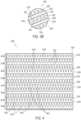
- FIG. 4a partial cross-sectional view 400 of the MCHX 300 of Figure 2 along 4-4 is shown according to an embodiment. That is only a portion of the cross-section along 4-4 is shown.
- the plurality of the working fluid layers 324, the plurality of the sealing layers 326, and the plurality of the air-passage layers 328, each depicted in Figure 3are also depicted in Figure 4 .
- Each of the working fluid layers 324includes a plurality of working fluid channels 402 and each of the air-passage layers 328 includes the plurality of the air-passage channels 320.
- the working fluid channels 402 and air-passage channels 320are microchannels and the sizes generally range from 0.005 inches to 0.120 inches.
- the layers 324-328be bonded together by diffusion bonding or brazing. Accordingly, boundaries between the layers would be generally indistinguishable.
- a plurality of working/sealing sets 404are created via diffusion bonding or brazing. That is, each of the working fluid layers 324 is respectively diffusion bonded or brazed to each of sealing layers 326 to form the plurality of working/sealing sets 404.
- the sealing layers 402are un-etched, and each effectively creates a seal over the working fluid layer 324 while leaving the working fluid channels 402 of the sets 404 open for fluid flow.
- each of the working/sealing sets 404have a high structural integrity since they, in some aspects, act as a pressure vessel for the high pressure working fluid that flows therethrough. Since the working fluid channels 402 are microchannels, each of the working/sealing sets 404 accommodate a high pressure of working fluid without a corresponding high stress in each of the working/sealing sets 404 due to the low value of Pr/t stress, where "P” is internal pressure, "r” is channel diameter, and "t” is channel wall thickness.
- eachis respectively diffusion bonded or brazed to each of the air-passage layers 328.
- each of the air-passage layers 328is sandwiched between two of the working/sealing sets 404.
- each of the MCHXs 300may be employed, each having one hundred and thirty-two air-passage layers 328 with each air-passage channel 320 thereof having a dimension of 0.0225 inches by 0.0225 inches.
- Each of the eight MCHX 300would also employ one hundred and thirty-three working/sealing sets 404 with the sets 404 being approximately 0.020 inches thick.
- each of the working/sealing sets 404may have an approximately 0.005 inch thick un-etched sealing layer 326 and an approximately 0.015 inch thick working fluid layer 324.
- the etch depth of the working fluid channels 402may be approximately 0.010 inches. It is noted that according to other embodiments, other dimensions may instead be employed that fall within the microchannel range set forth above.
- FIG. 5a cross-sectional view of the MCHX 300 of Figure 3a along 5-5 is shown according to an embodiment.
- the cross-sectional view shown in Figure 5depicts a single working fluid layer 500, such as one of the working fluid layers 324 of Figures 3a-4 .
- the single working fluid layer 500 of Figure 5includes the plurality of working fluid channels 402, a plurality of raised pedestals 502, a plurality of substrate rises 504, a substrate perimeter 506, and an internal intake and outtake manifolds 508, 510, respectively, around the raised pedestals 502.
- the internal intake and outtake manifold 508, 510are generally the same depth as the working fluid channels 402.
- An upper and lower portion 512, 514(respectively shown in phantom) of the respective external outtake and intake manifolds 314, 312 of Figure 3 are also shown.
- the substrate rises 504, substrate perimeter 506, and the upper and lower portions 512, 514, respectively,are generally at the same height.
- Figure 5also depicts an external outtake manifold void 516 and an external intake manifold void 518. It is noted that according to an embodiment, external intake and outtake manifolds are not required since the internal intake manifold 508 and the internal outtake manifold 510 may be all that is needed to accommodate the transfer of the working fluid.
- the single working fluid layer 500is configured to allow a working fluid to enter from the external intake manifold void 518 into the internal intake manifold 508 around the pedestals 502 therein and pass into the plurality of working fluid channels 402.
- the working fluidbe a mixture such as a water-ammonia mixture.
- the working fluidpasses through the working fluid channels 402 and enters the internal outtake manifold 510 where it passes around the raised pedestals 502 therein and out the external outtake manifold void 516.
- the single working fluid layer 500is for an evaporative or boiling type MCHX such as intercooler-type MCHX 108 depicted in Figures 1 and 2 .
- the volume of the internal outtake manifold 510 of Figure 5is larger than the volume of the internal intake manifold 508.
- the larger volume of the internal outtake manifold 510accommodates the expansion of the working fluid from a liquid to a gas or supercritical fluid as it passes through the working fluid channels 402.
- the internal outtake manifoldhas a smaller volume than the internal intake manifold to accommodate the decrease in volume (e.g., condensing from a gas to a liquid) of the working fluid as it passes through the working fluid channels thereof.
- the arrangement of the raised pedestals 502 shownis configured to aid the flow of the working fluid.
- the arrangement of the raised pedestals 502 in the internal intake manifold 508aides in the distribution of the working fluid into the working fluid channels 402.
- the arrangement of the pedestals 502 in the upper working fluid region 510aides in the transfer of the working fluid out of the working fluid channels 402 and into the external outtake manifold void 516.
- the size of the working fluid channels 402generally ranges from 0.005 inches to 0.120 inches.
- the single working fluid layer 500is manufactured by a process that combines portions of printed circuit board manufacturing (e.g., masking, ultraviolet exposure, and mask development) with electrochemical machining/etching in sheet metal. With regards to the etching, isotropic or anisotropic etching may be employed.
- the design of the single working fluid layer 500is easily configurable.
- the embodiment of Figure 5depicts straight working fluid channels 402 and round raised pedestals 502
- other embodimentsmay employ different shapes of these features.
- the design artworkmay be relatively easily modified to employ pedestals that are not round and/or channels that are staggered or even snake shaped. It is the use of the resist, mask, expose, develop, and electrochemical etching/machining processes employed in the printed circuit board sector that make the design art work easily configurable.
- each working fluid layere.g., single working fluid layer 500 of Figure 5
- a sealing layere.g., the sealing layer 326 of Figure 4
- the sealing layer 600 of Figure 6is configured to have generally the same footprint as the working fluid layer (e.g., the working fluid layer 500 of Figure 5 ).
- the sealing layer 600is bonded via diffusion bonding or brazing to the raised substrate of the working fluid layer.
- the sealing layer 600is bonded to the substrate rises 504, the substrate perimeter 506, the raised pedestals 502, and the upper and lower portions of the respective external outtake and intake manifolds 512, 514 of the single working fluid layer 500. Since neither the working fluid channels 402 nor the internal outtake and intake manifolds 510, 508, respectively, around the raised pedestals 502 are bonded to the sealing layer 600, the working fluid is allowed to move into the internal intake manifold 508 via the external intake manifold void 518, then into the working fluid channels 402, out into the internal outtake manifold 510, and then out through the external outtake manifold void 516.
- sealing layersmay take on shapes other than a saddle shape.
- the air-passage layer 700includes a plurality of air-passage channels 702, a plurality of air-passage substrate rises 704, a first substrate perimeter 706, a portion of external outtake manifold region 708 (shown in phantom), a second substrate perimeter 710, and a portion of an external intake manifold region 712 (shown in phantom). Further, Figure 7a also depicts a portion of an external intake manifold void 714 and an external outtake manifold void 716.
- the air-passage channels 702 and the air-passage substrate rises 704extend from a top end 718 of the air-passage layer 700 to a bottom end 720 of the air-passage layer 700. Further, according to the present embodiment, the air-passage channels 702 generally converge at the bottom end 720 relative to the top end 718. As such, if the air-passage layer 700 is employed in an intercooler-type MCHX (e.g., intercooler-type MCHX 108 of Figures 1 and 2 ), the convergence compensates for any loss of air stream velocity through the air-passage channels 702 of Figure 7a due to cooling. Other embodiments, however, are envisioned having convergence instead on the top end 718 or no convergence at all.
- intercooler-type MCHXe.g., intercooler-type MCHX 108 of Figures 1 and 2
- the air-passage substrate rises 704, first and second perimeters 706, 710, and the portions of the external outtake and intake manifolds 708, 712are generally at the same height. Accordingly, these areas 704-712 are diffusion bonded or brazed to respective working/sealing sets 404 of Figure 4 during manufacture.
- the air-passage channels 702 of Figure 7aare microchannels and generally range in size between 0.005 inches and 0.120inches.
- the small features of the of the air-passage channels 702enable a large air surface area of the air-passage layer 700 so that the product of the heat transfer coefficient times the surface area (i.e., the HA product) can be generally the same magnitude as the working fluid layer (e.g., working/sealing sets 404).
- an MCHX(e.g., intercooler-type MCHX 108 and condenser-type MCHX 118, each of Figures 1 and 2 , and MCHX 300 of Figure 3 ) can be a fraction of the volume of a conventional heat exchanger (not shown) with generally equivalent performance (e.g., air pressure loss and thermal efficiency).
- the air-passage layer 700is manufactured by a process that combines portions of printed circuit board manufacturing (e.g., masking, ultraviolet exposure, and mask development) with electrochemical machining/etching in sheet metal. With regards to the etching, isotropic or anisotropic etching may be employed.
- the design of thereofis configurable.
- the embodiment of Figure 7adepicts straight air-passage channels 702
- other embodimentmay employ different shapes of this feature.
- the design artworkmay be relatively easily modified to create staggered or snake shaped air-passage microchannels.
- embodimentsare not dictated by the saddle shape shown in Figure 7a . That is, air-passage layers may take shapes other than a saddle shape.
- figure 7bdepicts a perspective view of a portion of air-passage layer 700 according to an embodiment.
- Figure 7billustrates that it is contemplated that the air-passage channels 702 and the air-passage substrate rises 704 are on both sides of air-passage layer 700.
- MCHXssuch as MCHX 108 and 118, both of Figures 1 and 2 , and MCHX 300 of Figure 3 are comprised of a plurality of microchannel layers (e.g., working fluid layer 324 shown in Figures 4 and 5 and air-passage layer 700 shown in figure 7 ).
- Such MCHXshave a high level or porosity, where porosity is a total void volume (i.e., the sum of each manifold volume and each passage or channel volume) over the total MCHX volume.
- a typical heat exchangermay have a porosity in the range from twenty to thirty percent
- embodiments of the MCHX discussed in detail hereinmay have a porosity in the range of thirty to seventy percent.
- the MCHXs(i.e., 108 and 118 both of Figures 1 and 2 , and 300 of Figure 3 ) and the embodiments thereof discussed in detail above, whether they are of the intercooler or condenser-type MCHXs, have the advantages of having a small size and weight for a given thermal effectiveness and pressure drop. As discussed above, they have a high porosity. Accordingly, these types of MCHXs can be utilized in applications that have tight size and weight requirements. For example, the MCHXs discussed above and the embodiments thereof can be utilized in aerospace application where size and weight requirements need to be met. Further, since an intermediate fluid is utilized (e.g., working fluid 330 of Figure 3a ), the need for heavy and complex ducting often needed for air-to-air type heat exchangers can be avoided.
- an intermediate fluide.g., working fluid 330 of Figure 3a
Landscapes
- Engineering & Computer Science (AREA)
- Mechanical Engineering (AREA)
- General Engineering & Computer Science (AREA)
- Chemical & Material Sciences (AREA)
- Combustion & Propulsion (AREA)
- Physics & Mathematics (AREA)
- Thermal Sciences (AREA)
- Heat-Exchange Devices With Radiators And Conduit Assemblies (AREA)
Description
- This disclosure was made with government support under FA8650-09-D-2921 0009 awarded by the United States Air Force. The government has certain rights in the disclosure.
- An improved heat exchanger for use in a gas turbine engine is disclosed.
- Heat exchangers may be employed in the gas turbine engine sector (e.g., the aerospace sector) for the purpose of transferring heat between a core air stream and a bypass stream. Historically, air to air type heat exchangers are employed for this purpose. These types of heat exchangers however can require complex ducting, which adds system weight, costs, and can reduce their effectiveness. Further prior art is disclosed in
US2010314088A1 ,EP2412631A2 ,US2011146226A1 , andUS2007298486A1 . Accordingly, there is room for further improvements in this area. - According to the present disclosure, there is provided a heat exchange system, as set forth in the appended claims.
- While the claims are not limited to a specific illustration, an appreciation of the various aspects is best gained through a discussion of various examples thereof. Referring now to the drawings, exemplary illustrations are shown in detail. Although the drawings represent the illustrations, the drawings are not necessarily to scale and certain features may be exaggerated to better illustrate and explain an innovative aspect of an example. Further, the exemplary illustrations described herein are not intended to be exhaustive or otherwise limiting or restricted to the precise form and configuration shown in the drawings and disclosed in the following detailed description. Exemplary illustrations are described in detail by referring to the drawings as follows:
FIG. 1 illustrates an exemplary gas turbine;FIG. 2 illustrates a exemplary microchannel heat exchange system according to an embodiment;FIG. 3a illustrates an exemplary microchannel heat exchanger (MCHX) according to an embodiment;FIG. 3b illustrates an exaggerated view of a region of the exemplary MCHX ofFigure 3a according to an embodiment;FIG. 4 illustrates a partial cross-sectional view ofFIG. 3a along 4-4 according to an embodiment;FIG. 5 illustrates a cross-sectional view ofFIG. 3a along 5-5 according to an embodiment;FIG. 6 illustrates an exemplary MCHX sealing layer according to an embodiment;FIG. 7a illustrates an exemplary MCHX air-passage layer according to an embodiment; andFIG. 7b illustrates a perspective view of a portion of the exemplary MCHX air-passage layer ofFIG. 7a according to an embodiment.Figure 1 illustrates an exemplarygas turbine engine 100, which includes afan 102, a vane/strut 104, acore stream diffuser 106, an intercooler-type microchannel heat exchanger (MCHX) 108, a highpressure compressor nozzle 110, and a closedcycle turbine 112. Ambient air enters past thefan 102 and is directed past thecore stream diffuser 106 as acore air stream 114 that proceeds through the intercooler-type MCHX 108 where it is cooled.- The
gas turbine engine 100 also includes abypass stream diffuser 116, a condenser-type MCHX 118, and anexit nozzle 120. Fan stream air in the form of abypass air stream 122 proceeds past thebypass stream diffuser 116 to the condenser-type MCHX 118, and passes through the condenser-type MCHX 118 where thebypass air stream 122 is heated before exiting theexit nozzle 120. As will be discussed in detail below with respect toFigure 2 , according to an embodiment, a working fluid (not shown) that passes through the intercooler-type MCHX 108 ofFigure 1 also passes through the condenser-type MCHX 118. Accordingly, thecore air stream 114 heats the working fluid in the intercooler-type MCHX 108 (i.e., heat is transferred from thecore air stream 114 to the working fluid in the intercooler-type MCHX 108) while thebypass air stream 122 cools the working fluid in the condenser-type MCHX 118 (i.e., heat is transferred from the working fluid in the condenser-type MCHX 118 to the bypass air stream 122). - Further details regarding the intercooler-
type MCHX 108 and the condenser-type MCHX 118 will be set forth below with respect toFigures 2-7 . - With reference now to
Figure 2 , adetailed view 200 of a portion ofgas turbine engine 100 ofFigure 1 employing a microchannel heat exchange system is shown according to an embodiment. The portions of thegas turbine engine 100 shown in bothFigures 1 and2 include the intercooler-type MCHX 108, the closedcycle turbine 112 , the condenser-type MCHX 118, thecore stream diffuser 106, and thebypass stream diffuser 116.Figure 2 also depicts an accumulator/separator 202, a liquidworking fluid pump 204, and a series of workingfluid piping 206. - According to an embodiment, a
core air stream 208 passes through thecore stream diffuser 106 and through the intercooler-type MCHX 108. As thecore air stream 208 passes though the intercooler-type MCHX 108, a working fluid (not shown) therein changes phase from a liquid to a gas as heat from thecore air stream 208 is transferred to the working fluid in the intercooler-type MCHX 108. Alternatively, it is contemplated that the working fluid instead changes from a liquid to a supercritical fluid. Referring back to the present embodiment, after passing through the intercooler-type MCHX 108 the working fluid then passes via the series of workingfluid piping 206 as a high pressure gas or supercritical fluid to the closedcycle turbine 112 thus generating power. The working fluid is then conveyed via the series of workingfluid piping 206 as a low pressure gas or gas and liquid mixture to the condenser-type MCHX 118. The condenser-type MCHX 118 causes the working fluid therein to change phase once again, this time from a gas to a liquid by transferring heat from the working fluid to abypass air stream 210 that passes through the condenser-type MCHX 118 via thebypass stream diffuser 116. - Accordingly, heat has been transferred from the
core air stream 208 to thebypass air stream 210 via the working fluid. - After the working fluid passes through the condenser-
type MCHX 118, the working fluid is then conveyed via the series of workingfluid piping 206 as a liquid to the accumulator/separator 202, then to theliquid pump 204, and then again to the intercooler-type MCHX 108. As will be appreciated, piping configurations different than the configuration of the series of workingfluid piping 206 shown inFigure 2 may be employed to couple together two MCHXs such as intercooler-type MCHX 108 and condenser-type MCHX 118. - By employing a heat exchange or management system having the intercooler-
type MCHX 108 functionally or fluidly connected to the condenser-type MCHX 118 as shown inFigure 2 , heavy and complex ducting previously required with air-to-air heat exchange systems can be avoided or at least minimized. - Turning now to
Figures 3a-3b , anMCHX 300 and anexaggerated view 302 of a portion thereof are shown according to an embodiment. The MCHX 300 includes aninlet 304 on afront side 306 and anoutlet 308 also on thefront side 306. It is noted, that according to other embodiments, the outlet may be on aback side 310 rather than thefront side 306. Alternatively, theoutlet 308 may remain on thefront side 306, while theinlet 304 is instead positioned on theback side 310. Indeed, according to embodiments, theoutlet 308 andinlet 304 may be on any side of the MCHX 300. - Referring to the present embodiment, though not required, it is contemplated that the
MCHX 300 have anexternal intake manifold 312 and anexternal outtake manifold 314, where each is shown in phantom. The MCHX 300 also includes atop side 316 and abottom side 318. - The
exaggerated view 302 ofFigure 3b is of region A on thetop side 316 of theMCHX 300 shown inFigure 3a . As illustrated in theexaggerated view 302, thetop side 316 includes a plurality of air-passage channels 320. These air-passage channels 320 extend through theMCHX 300 from thetop side 316 to thebottom side 318. The air-passage channels 320 are configured to allowair 322 to pass through theMCHX 300. That is, the air-passage channels 320 are configured to allowair 322 to enter thetop side 316 of theMCHX 300 and exit through thebottom side 318 of theMCHX 300. Further information regarding the plurality of air-passage channels 320 will be set forth in detail below with respect toFigures 4 and7a-b . - The
exaggerated view 302 ofFigure 3b also illustrates that theMCHX 300 is comprised of a plurality of layers. The layers include a plurality of workingfluid layers 324, a plurality of sealinglayers 326, and a plurality of air-passage layers 328 that includes the plurality of air-passage channels 320. Each layer 324-328 extends from thetop side 316 of theMCHX 300 to thebottom side 318 of theMCHX 300. It is contemplated that these layers 324-328 include nickel, titanium, and/or aluminum alloys. - According to an embodiment, a working
fluid 330 enters theMCHX 300 via theinlet 304 into theexternal intake manifold 312, passes through the workingfluid layers 324 that run parallel with the air-passage channels 320 of the air-passage layers 328, through theexternal outtake manifold 314, and then out theoutlet 308. The workingfluid 330 may be almost any fluid or mixture, including high pressure gases, single component 2-phase fluids, multi-component mixtures 2-phase fluids, single component and multi-component supercritical fluids, and single and multi-component liquids. - The
MCHX 300 is generally a counter flow-type heat exchanger. That is, asair 322, such as a core stream or a bypass stream, moves through theMCHX 300 via the air-passage channels 320 in afirst direction 332, heat is transferred between theair 322 and the workingfluid 330 that is moving in asecond direction 334 that is opposite thefirst direction 332. Accordingly, an efficient heat transfer occurs between theair 322 in the air-passage channels 320 and the workingfluid 330 moving in an opposite direction in the workingfluid layer 324. - If the
MCHX 300 functions as an intercooler, theair 322 entering thetop side 316 of theMCHX 300 is warmer than the workingfluid 330 entering theinlet 304. As such, heat is transferred from theair 322 to the workingfluid 330 as each travel in opposite directions through theMCHX 300. - The
MCHX 300, if configured to act as an intercooler, is configured to allow the workingfluid 330 to take on a gaseous form as it passes through the workingfluid layer 324 and absorbs heat from theair 322 passing in the opposite direction through the air-passage layers 328. Accordingly, the workingfluid 330 entering theinlet 304 is in a high pressure liquid form and the working fluid leaving theMCHX 300 via theoutlet 308 is in a gaseous form (e.g., steam form). It is noted that whether the workingfluid 330 is in a fluid or gaseous form, it is still considered a working fluid. - Alternatively, the
MCHX 300 may be configured to serve as a condenser-type MCHX. According to such an embodiment, the workingfluid 330 passes heat to theair 322 and the workingfluid 330 condenses as it passes through the workingfluid layer 324. - It is noted that the saddle shape of the
MCHX 300 depicted infigure 3 may be beneficial in a variety of applications. For example,MCHX 300 may be an intercooler-type heat exchanger that may be fit between an intermediate pressure compressor and a high pressure compressor in a three spool high bypass turban engine. It is noted, however, that embodiments are not dictated by the shape of theMCHX 300 shown inFigure 3 . That is, alternate embodiments may employ other shapes that also employ microchannel air-passage and working fluid layers. Further, embodiments may also be implemented in applications other than three spool applications, such as single or double spool (shaft) applications. - Referring now to
Figure 4 , a partialcross-sectional view 400 of theMCHX 300 ofFigure 2 along 4-4 is shown according to an embodiment. That is only a portion of the cross-section along 4-4 is shown. As seen inFigure 4 , the plurality of the workingfluid layers 324, the plurality of the sealing layers 326, and the plurality of the air-passage layers 328, each depicted inFigure 3 , are also depicted inFigure 4 . Each of the workingfluid layers 324 includes a plurality of workingfluid channels 402 and each of the air-passage layers 328 includes the plurality of the air-passage channels 320. As air (not shown) passes through the air-passage channels 320, heat is transferred between the air and the working fluid (not shown) that is passing in the opposite direction through the workingfluid channels 402. The workingfluid channels 402 and air-passage channels 320 are microchannels and the sizes generally range from 0.005 inches to 0.120 inches. - It is contemplated that during manufacturing, the layers 324-328 be bonded together by diffusion bonding or brazing. Accordingly, boundaries between the layers would be generally indistinguishable.
- Further, it is contemplated that during manufacturing, a plurality of working/sealing
sets 404 are created via diffusion bonding or brazing. That is, each of the workingfluid layers 324 is respectively diffusion bonded or brazed to each of sealinglayers 326 to form the plurality of working/sealing sets 404. According to an embodiment, the sealing layers 402 are un-etched, and each effectively creates a seal over the workingfluid layer 324 while leaving the workingfluid channels 402 of thesets 404 open for fluid flow. - These working/sealing
sets 404 have a high structural integrity since they, in some aspects, act as a pressure vessel for the high pressure working fluid that flows therethrough. Since the workingfluid channels 402 are microchannels, each of the working/sealing sets 404 accommodate a high pressure of working fluid without a corresponding high stress in each of the working/sealing sets 404 due to the low value of Pr/t stress, where "P" is internal pressure, "r" is channel diameter, and "t" is channel wall thickness. - After the
sets 404 are created, each is respectively diffusion bonded or brazed to each of the air-passage layers 328. In other words, each of the air-passage layers 328 is sandwiched between two of the working/sealing sets 404. - According to an embodiment where the MCHX, such as
MCHX 300, is configured as an intercooler in a turbofan environment, eight of theMCHXs 300 may be employed, each having one hundred and thirty-two air-passage layers 328 with each air-passage channel 320 thereof having a dimension of 0.0225 inches by 0.0225 inches. Each of the eightMCHX 300 would also employ one hundred and thirty-three working/sealing sets 404 with thesets 404 being approximately 0.020 inches thick. In such an embodiment, each of the working/sealing sets 404 may have an approximately 0.005 inch thickun-etched sealing layer 326 and an approximately 0.015 inch thick workingfluid layer 324. The etch depth of the workingfluid channels 402 may be approximately 0.010 inches. It is noted that according to other embodiments, other dimensions may instead be employed that fall within the microchannel range set forth above. - With reference now to
Figure 5 , a cross-sectional view of theMCHX 300 ofFigure 3a along 5-5 is shown according to an embodiment. The cross-sectional view shown inFigure 5 depicts a single working fluid layer 500, such as one of the workingfluid layers 324 ofFigures 3a-4 . The single working fluid layer 500 ofFigure 5 includes the plurality of workingfluid channels 402, a plurality of raisedpedestals 502, a plurality of substrate rises 504, asubstrate perimeter 506, and an internal intake andouttake manifolds outtake manifold fluid channels 402. An upper andlower portion 512, 514 (respectively shown in phantom) of the respective external outtake andintake manifolds Figure 3 are also shown. With continued reference toFigure 5 , it is noted that the substrate rises 504,substrate perimeter 506, and the upper andlower portions Figure 5 also depicts an external outtakemanifold void 516 and an externalintake manifold void 518. It is noted that according to an embodiment, external intake and outtake manifolds are not required since theinternal intake manifold 508 and theinternal outtake manifold 510 may be all that is needed to accommodate the transfer of the working fluid.- According to the present embodiment, the single working fluid layer 500 is configured to allow a working fluid to enter from the external
intake manifold void 518 into theinternal intake manifold 508 around thepedestals 502 therein and pass into the plurality of workingfluid channels 402. It is contemplated that the working fluid be a mixture such as a water-ammonia mixture. The working fluid passes through the workingfluid channels 402 and enters theinternal outtake manifold 510 where it passes around the raisedpedestals 502 therein and out the external outtakemanifold void 516. It is noted that, according to the embodiment depicted inFigure 5 , the single working fluid layer 500 is for an evaporative or boiling type MCHX such as intercooler-type MCHX 108 depicted inFigures 1 and2 . Accordingly, the volume of theinternal outtake manifold 510 ofFigure 5 is larger than the volume of theinternal intake manifold 508. The larger volume of theinternal outtake manifold 510 accommodates the expansion of the working fluid from a liquid to a gas or supercritical fluid as it passes through the workingfluid channels 402. However, in an alternate embodiment not shown where the MCHX is a condenser-type MCHX, the internal outtake manifold has a smaller volume than the internal intake manifold to accommodate the decrease in volume (e.g., condensing from a gas to a liquid) of the working fluid as it passes through the working fluid channels thereof. - With continued reference to
Figure 5 , the arrangement of the raisedpedestals 502 shown is configured to aid the flow of the working fluid. For example, the arrangement of the raisedpedestals 502 in theinternal intake manifold 508 aides in the distribution of the working fluid into the workingfluid channels 402. Likewise, the arrangement of thepedestals 502 in the upper workingfluid region 510 aides in the transfer of the working fluid out of the workingfluid channels 402 and into the external outtakemanifold void 516. - The size of the working
fluid channels 402 generally ranges from 0.005 inches to 0.120 inches. The single working fluid layer 500 is manufactured by a process that combines portions of printed circuit board manufacturing (e.g., masking, ultraviolet exposure, and mask development) with electrochemical machining/etching in sheet metal. With regards to the etching, isotropic or anisotropic etching may be employed. - Due to the manner of manufacturing of the single working fluid layer 500, the design of the single working fluid layer 500 is easily configurable. For example, whereas the embodiment of
Figure 5 depicts straight workingfluid channels 402 and round raisedpedestals 502, other embodiments may employ different shapes of these features. For example, though not shown, the design artwork may be relatively easily modified to employ pedestals that are not round and/or channels that are staggered or even snake shaped. It is the use of the resist, mask, expose, develop, and electrochemical etching/machining processes employed in the printed circuit board sector that make the design art work easily configurable. - It is noted that embodiments are not dictated by the saddle shape shown in
Figure 5 . That is, working fluid layers may take on shapes other than a saddle shape. - Referring now to
Figure 6 , asealing layer 600 is shown according to an embodiment. As discussed above with respect toFigure 4 , it is contemplated that each working fluid layer (e.g., single working fluid layer 500 ofFigure 5 ) is bonded to a sealing layer (e.g., thesealing layer 326 ofFigure 4 ), thus creating a working sealing set such as working/sealing set 404 ofFigure 4 . Accordingly, thesealing layer 600 ofFigure 6 is configured to have generally the same footprint as the working fluid layer (e.g., the working fluid layer 500 ofFigure 5 ). Thesealing layer 600 is bonded via diffusion bonding or brazing to the raised substrate of the working fluid layer. For example, with reference toFigures 5 and6 , thesealing layer 600 is bonded to the substrate rises 504, thesubstrate perimeter 506, the raisedpedestals 502, and the upper and lower portions of the respective external outtake andintake manifolds fluid channels 402 nor the internal outtake andintake manifolds pedestals 502 are bonded to thesealing layer 600, the working fluid is allowed to move into theinternal intake manifold 508 via the externalintake manifold void 518, then into the workingfluid channels 402, out into theinternal outtake manifold 510, and then out through the external outtakemanifold void 516. - It is noted that embodiments are not dictated by the saddle shape shown in
Figure 6 . That is, sealing layers may take on shapes other than a saddle shape. - With reference now to
Figure 7a , an air-passage layer 700 is shown according to an embodiment. The air-passage layer 700 includes a plurality of air-passage channels 702, a plurality of air-passage substrate rises 704, afirst substrate perimeter 706, a portion of external outtake manifold region 708 (shown in phantom), asecond substrate perimeter 710, and a portion of an external intake manifold region 712 (shown in phantom). Further,Figure 7a also depicts a portion of an externalintake manifold void 714 and an external outtakemanifold void 716. - It is noted that the air-
passage channels 702 and the air-passage substrate rises 704 extend from atop end 718 of the air-passage layer 700 to abottom end 720 of the air-passage layer 700. Further, according to the present embodiment, the air-passage channels 702 generally converge at thebottom end 720 relative to thetop end 718. As such, if the air-passage layer 700 is employed in an intercooler-type MCHX (e.g., intercooler-type MCHX 108 ofFigures 1 and2 ), the convergence compensates for any loss of air stream velocity through the air-passage channels 702 ofFigure 7a due to cooling. Other embodiments, however, are envisioned having convergence instead on thetop end 718 or no convergence at all. - The air-passage substrate rises 704, first and
second perimeters intake manifolds Figure 4 during manufacture. - The air-
passage channels 702 ofFigure 7a are microchannels and generally range in size between 0.005 inches and 0.120inches. The small features of the of the air-passage channels 702 enable a large air surface area of the air-passage layer 700 so that the product of the heat transfer coefficient times the surface area (i.e., the HA product) can be generally the same magnitude as the working fluid layer (e.g., working/sealing sets 404). Accordingly, an MCHX (e.g., intercooler-type MCHX 108 and condenser-type MCHX 118, each ofFigures 1 and2 , andMCHX 300 ofFigure 3 ) can be a fraction of the volume of a conventional heat exchanger (not shown) with generally equivalent performance (e.g., air pressure loss and thermal efficiency). - The air-
passage layer 700 is manufactured by a process that combines portions of printed circuit board manufacturing (e.g., masking, ultraviolet exposure, and mask development) with electrochemical machining/etching in sheet metal. With regards to the etching, isotropic or anisotropic etching may be employed. - Due to the manner of manufacturing the air-
passage layer 700, the design of thereof is configurable. For example, whereas the embodiment ofFigure 7a depicts straight air-passage channels 702, other embodiment may employ different shapes of this feature. For example, though not shown, the design artwork may be relatively easily modified to create staggered or snake shaped air-passage microchannels. Further, it is noted that embodiments are not dictated by the saddle shape shown inFigure 7a . That is, air-passage layers may take shapes other than a saddle shape. - Referring now to
Figures 7b and 7a , wherefigure 7b depicts a perspective view of a portion of air-passage layer 700 according to an embodiment.Figure 7b illustrates that it is contemplated that the air-passage channels 702 and the air-passage substrate rises 704 are on both sides of air-passage layer 700. - According to embodiments, MCHXs such as
MCHX Figures 1 and2 , andMCHX 300 ofFigure 3 are comprised of a plurality of microchannel layers (e.g., workingfluid layer 324 shown inFigures 4 and5 and air-passage layer 700 shown infigure 7 ). Such MCHXs have a high level or porosity, where porosity is a total void volume (i.e., the sum of each manifold volume and each passage or channel volume) over the total MCHX volume. Whereas a typical heat exchanger (not shown) may have a porosity in the range from twenty to thirty percent, embodiments of the MCHX discussed in detail herein may have a porosity in the range of thirty to seventy percent. - The MCHXs (i.e., 108 and 118 both of
Figures 1 and2 , and 300 ofFigure 3 ) and the embodiments thereof discussed in detail above, whether they are of the intercooler or condenser-type MCHXs, have the advantages of having a small size and weight for a given thermal effectiveness and pressure drop. As discussed above, they have a high porosity. Accordingly, these types of MCHXs can be utilized in applications that have tight size and weight requirements. For example, the MCHXs discussed above and the embodiments thereof can be utilized in aerospace application where size and weight requirements need to be met. Further, since an intermediate fluid is utilized (e.g., workingfluid 330 ofFigure 3a ), the need for heavy and complex ducting often needed for air-to-air type heat exchangers can be avoided. - It will be appreciated that the aforementioned method and devices may be modified to have some components and steps removed, or may have additional components and steps added, all of which are deemed to be within the spirit of the present disclosure. Even though the present disclosure has been described in detail with reference to specific embodiments, it will be appreciated that the various modifications and changes can be made to these embodiments without departing from the scope of the present disclosure as set forth in the claims. The specification and the drawings are to be regarded as an illustrative thought instead of merely restrictive thought.
Claims (11)
- A microchannel heat exchanger (MCHX) system (200) configured to transport heat within a gas turbine engine (100), the MCHX system comprising:a first MCHX (108, 118, 300) comprising:a first layer (328, 700) having a plurality of electrochemically etched air-passage microchannels (320, 702) configured to convey a first air stream (114, 122, 208, 210, 322) through the first MCHX in a first direction (332); anda second layer (324, 500) having a plurality of electrochemically etched working fluid microchannels (402) configured to convey a working fluid (330) through the first MCHX in a second direction (334) opposite the first direction (332);wherein the second layer (324, 500) of the first MCHX (108, 118, 300) further comprises:an internal intake manifold (508) electrochemically etched into the second layer (324, 500), wherein the internal intake manifold (508) is configured to convey the working fluid (330) to the plurality of electrochemically etched working fluid microchannels (402); andan internal outtake manifold (510) electrochemically etched into the second layer (324, 500), wherein the internal outtake manifold (510) is configured to receive the working fluid (330) from the plurality of electrochemically etched working fluid microchannels (402);characterized in thatthe second layer (324, 500) of the first MCHX (108, 118, 300) includes an arrangement of raised pedestals (502) disposed in the internal intake manifold (508) and the internal outtake manifold (510), respectively, configured to aid the flow of the working fluid;and in thatthe first MCHX (108, 118, 300) further comprises a sealing layer (326, 600) bonded to the second layer (324, 500) to provide a working/sealing set (404), wherein the sealing layer (326, 600) is bonded via diffusion bonding or brazing to a raised substrate (502, 504, 506) of the second layer (324, 500).
- The MCHX system (200) of claim 1, further comprising a second MCHX (108, 118, 300) fluidly coupled to the first MCHX (108, 118, 300), the second MCHX is configured to convey heat between a second air stream (114, 122, 208, 210, 322) and the working fluid (330), and wherein the first air stream is a core air stream (114, 208, 322) and the second air stream is a bypass air stream (122, 210, 322), and wherein the MCHX system (200) is configured to convey heat between the core air stream and the bypass air stream.
- The MCHX system (200) of claim 2, wherein the first MCHX is an intercooler MCHX (108) and the second MCHX is a condenser MCHX (118).
- The MCHX system (200) as in any of claims 1 to 3, wherein the first MCHX (108, 118, 300) has a porosity between 0.30 and 0.70, and wherein the porosity is a sum of each void volume in the first MCHX divided by a total volume of the first MCHX.
- The MCHX system (200) as in any of claims 1 to 4, wherein the plurality of electrochemically etched air-passage microchannels (320, 702) converge at a first end (718, 720) of the first layer (328, 700) to converge a plurality of air streams (114, 122, 208, 210, 322) passing through the first MCHX, wherein the first air stream (114, 122, 208, 210, 322) entering the plurality of electrochemically etched air-passage microchannels comprises the plurality of air streams passing through the first MCHX.
- The MCHX system (200) as in any of claims 1 to 5, wherein an internal volume of the internal intake manifold (508) is less than an internal volume of the internal outtake manifold (510).
- The MCHX system (200) of claim 1, wherein the first layer (328, 700) of the first MCHX (108, 118, 300) is diffusion bonded or brazed between two working/sealing sets (404).
- The MCHX system (200) as in any of claims 1 to 7, wherein the first layer (328, 700) includes a plurality of air-passage substrate rises (704), wherein the plurality of electrochemically etched air-passage microchannels (320, 702) and the plurality of air-passage substrate rises (704) extends from a first end (718) of the first layer (328, 700) to a second end (720) of the first layer (328, 700).
- The MCHX system (200) of claim 8, wherein the plurality of electrochemically etched air-passage microchannels (320, 702) and the plurality of air-passage substrate rises (704) are on a first side and on a second side of the first layer (328, 700), and wherein the first side is opposite to the second side.
- The MCHX system (200) as in any of claims 1 to 9, wherein an inner dimension of each electrochemically etched air-passage microchannel (320, 702) and each electrochemically etched working fluid microchannel (402) is no less than 0.005 inches (0.127 mm) and no more than 0.120 inches (3.048 mm).
- A gas turbine engine (100) comprising the MCHX system (200) as in any of claims 1 to 10.
Applications Claiming Priority (2)
| Application Number | Priority Date | Filing Date | Title |
|---|---|---|---|
| US201461943064P | 2014-02-21 | 2014-02-21 | |
| EP15154715.5AEP2910887B1 (en) | 2014-02-21 | 2015-02-11 | Microchannel heat exchangers for gas turbine intercooling and condensing as well as corresponding method |
Related Parent Applications (1)
| Application Number | Title | Priority Date | Filing Date |
|---|---|---|---|
| EP15154715.5ADivisionEP2910887B1 (en) | 2014-02-21 | 2015-02-11 | Microchannel heat exchangers for gas turbine intercooling and condensing as well as corresponding method |
Publications (2)
| Publication Number | Publication Date |
|---|---|
| EP3572758A1 EP3572758A1 (en) | 2019-11-27 |
| EP3572758B1true EP3572758B1 (en) | 2023-04-05 |
Family
ID=52596308
Family Applications (2)
| Application Number | Title | Priority Date | Filing Date |
|---|---|---|---|
| EP19178904.9AActiveEP3572758B1 (en) | 2014-02-21 | 2015-02-11 | Microchannel heat exchangers for gas turbine intercooling and condensing |
| EP15154715.5AActiveEP2910887B1 (en) | 2014-02-21 | 2015-02-11 | Microchannel heat exchangers for gas turbine intercooling and condensing as well as corresponding method |
Family Applications After (1)
| Application Number | Title | Priority Date | Filing Date |
|---|---|---|---|
| EP15154715.5AActiveEP2910887B1 (en) | 2014-02-21 | 2015-02-11 | Microchannel heat exchangers for gas turbine intercooling and condensing as well as corresponding method |
Country Status (2)
| Country | Link |
|---|---|
| US (2) | US10371053B2 (en) |
| EP (2) | EP3572758B1 (en) |
Families Citing this family (18)
| Publication number | Priority date | Publication date | Assignee | Title |
|---|---|---|---|---|
| WO2013147953A1 (en)* | 2011-12-30 | 2013-10-03 | Rolls-Royce North American Technologies Inc. | Aircraft propulsion gas turbine engine with heat exchange |
| EP3572758B1 (en)* | 2014-02-21 | 2023-04-05 | Rolls-Royce Corporation | Microchannel heat exchangers for gas turbine intercooling and condensing |
| US10066550B2 (en) | 2014-05-15 | 2018-09-04 | Rolls-Royce North American Technologies, Inc. | Fan by-pass duct for intercooled turbo fan engines |
| US10782071B2 (en)* | 2017-03-28 | 2020-09-22 | General Electric Company | Tubular array heat exchanger |
| US10670346B2 (en)* | 2018-01-04 | 2020-06-02 | Hamilton Sundstrand Corporation | Curved heat exchanger |
| CN108979864A (en)* | 2018-08-08 | 2018-12-11 | 北京航空航天大学 | A kind of miniature gas turbine and regenerator |
| US11035626B2 (en)* | 2018-09-10 | 2021-06-15 | Hamilton Sunstrand Corporation | Heat exchanger with enhanced end sheet heat transfer |
| US10900509B2 (en)* | 2019-01-07 | 2021-01-26 | Rolls-Royce Corporation | Surface modifications for improved film cooling |
| JP6666500B1 (en)* | 2019-03-29 | 2020-03-13 | 三菱重工業株式会社 | High temperature component and method of manufacturing high temperature component |
| US11680753B2 (en) | 2019-11-14 | 2023-06-20 | Rolls-Royce Corporation | Fused filament fabrication of heat pipe |
| US11707788B2 (en) | 2019-11-14 | 2023-07-25 | Rolls-Royce Corporation | Fused filament fabrication of vacuum insulator |
| US11745264B2 (en) | 2019-11-14 | 2023-09-05 | Rolls-Royce Corporation | Fused filament fabrication of thermal management article |
| CN111140361B (en)* | 2019-12-24 | 2022-09-13 | 航天海鹰(哈尔滨)钛业有限公司 | Microchannel heat exchanger core for gas turbine system |
| JP6970360B2 (en) | 2020-02-10 | 2021-11-24 | ダイキン工業株式会社 | Heat exchanger and heat pump system with it |
| US20210404750A1 (en)* | 2020-06-26 | 2021-12-30 | Vacuum Process Engineering, Inc. | Integrated hybrid compact fluid heat exchanger |
| FI129583B (en)* | 2021-04-29 | 2022-05-13 | Napalmi Tietotekniikka Oy | Fan |
| US20240217665A1 (en)* | 2022-12-28 | 2024-07-04 | Joby Aero, Inc | Aircraft propulsion system with integrated fuel cell cooling |
| FR3159954A1 (en)* | 2024-03-05 | 2025-09-12 | Safran Aircraft Engines | Assembly for aircraft propulsion system, designed to facilitate the installation of elements close to each other |
Citations (1)
| Publication number | Priority date | Publication date | Assignee | Title |
|---|---|---|---|---|
| US20070298486A1 (en)* | 2006-06-16 | 2007-12-27 | Velocys Inc. | Microchannel Apparatus and Methods Of Conducting Unit Operations With Disrupted Flow |
Family Cites Families (89)
| Publication number | Priority date | Publication date | Assignee | Title |
|---|---|---|---|---|
| US2782009A (en)* | 1952-03-14 | 1957-02-19 | Gen Motors Corp | Heat exchangers |
| US3818984A (en)* | 1972-01-31 | 1974-06-25 | Nippon Denso Co | Heat exchanger |
| US3866674A (en)* | 1973-10-01 | 1975-02-18 | Gen Electric | Gas turbine regenerator |
| US4377025A (en)* | 1978-10-26 | 1983-03-22 | The Garrett Corporation | Method of mounting heat exchanger support system |
| DE3131091A1 (en)* | 1981-08-06 | 1983-02-24 | Klöckner-Humboldt-Deutz AG, 5000 Köln | RING-SHAPED RECUPERATIVE HEAT EXCHANGER |
| US4408833A (en)* | 1982-01-13 | 1983-10-11 | The United States Of America As Represented By The Secretary Of The Air Force | Hot pressed and diffusion bonded laser mirror heat exchanger |
| DE3521914A1 (en)* | 1984-06-20 | 1986-01-02 | Showa Aluminum Corp., Sakai, Osaka | HEAT EXCHANGER IN WING PANEL DESIGN |
| US5655600A (en)* | 1995-06-05 | 1997-08-12 | Alliedsignal Inc. | Composite plate pin or ribbon heat exchanger |
| WO1997003281A1 (en)* | 1995-07-10 | 1997-01-30 | Westinghouse Electric Corporation | Preheating of gas turbine fuel with compressed cooling air |
| US5931638A (en)* | 1997-08-07 | 1999-08-03 | United Technologies Corporation | Turbomachinery airfoil with optimized heat transfer |
| US20020119079A1 (en)* | 1999-12-10 | 2002-08-29 | Norbert Breuer | Chemical microreactor and microreactor made by process |
| US6584778B1 (en)* | 2000-05-11 | 2003-07-01 | General Electric Co. | Methods and apparatus for supplying cooling air to turbine engines |
| EP1506054B1 (en)* | 2002-03-26 | 2012-07-25 | Peter Prechtl | Micro-reactor and micro-channel heat exchanger |
| JP2004028538A (en)* | 2002-06-28 | 2004-01-29 | Sumitomo Precision Prod Co Ltd | Regenerative heat exchanger for micro gas turbine |
| US6622519B1 (en)* | 2002-08-15 | 2003-09-23 | Velocys, Inc. | Process for cooling a product in a heat exchanger employing microchannels for the flow of refrigerant and product |
| US7278472B2 (en)* | 2002-09-20 | 2007-10-09 | Modine Manufacturing Company | Internally mounted radial flow intercooler for a combustion air changer |
| AU2003286821A1 (en) | 2002-11-01 | 2004-06-07 | Cooligy, Inc. | Optimal spreader system, device and method for fluid cooled micro-scaled heat exchange |
| US7156159B2 (en)* | 2003-03-17 | 2007-01-02 | Cooligy, Inc. | Multi-level microchannel heat exchangers |
| JP2007515777A (en) | 2003-01-28 | 2007-06-14 | アドヴァンスト セラミックス リサーチ インコーポレイテッド | Microchannel heat exchanger and manufacturing method thereof |
| US6951243B2 (en)* | 2003-10-09 | 2005-10-04 | Sandia National Laboratories | Axially tapered and bilayer microchannels for evaporative coolling devices |
| US7316262B1 (en)* | 2004-01-26 | 2008-01-08 | Rini Technologies, Inc. | Method and apparatus for absorbing thermal energy |
| US6988367B2 (en)* | 2004-04-20 | 2006-01-24 | Williams International Co. L.L.C. | Gas turbine engine cooling system and method |
| CA2585772C (en) | 2004-11-03 | 2013-12-24 | Velocys, Inc. | Partial boiling in mini and micro-channels |
| EP1864749B1 (en)* | 2005-03-29 | 2014-01-22 | Neomax Materials Co., Ltd. | Brazing filler material, composite material for brazing and brazed structure joined by using those |
| EP1877174A1 (en)* | 2005-04-08 | 2008-01-16 | Velocys, Inc. | Flow control through plural, parallel connecting channels to/from a manifold |
| US8109324B2 (en) | 2005-04-14 | 2012-02-07 | Illinois Institute Of Technology | Microchannel heat exchanger with micro-encapsulated phase change material for high flux cooling |
| EP1890802A2 (en)* | 2005-05-25 | 2008-02-27 | Velocys, Inc. | Support for use in microchannel processing |
| CN101541522B (en)* | 2006-08-28 | 2012-07-18 | 丹塞姆空气调节有限公司 | Method for manufacturing a heat exchanger |
| US8387362B2 (en)* | 2006-10-19 | 2013-03-05 | Michael Ralph Storage | Method and apparatus for operating gas turbine engine heat exchangers |
| ES2935119T3 (en) | 2007-01-31 | 2023-03-01 | Chemours Co Fc Llc | A vapor compression heat transfer system |
| US20080264094A1 (en)* | 2007-04-30 | 2008-10-30 | Caterpillar Inc. | Cooling system with expansion driven fan |
| US9157687B2 (en)* | 2007-12-28 | 2015-10-13 | Qcip Holdings, Llc | Heat pipes incorporating microchannel heat exchangers |
| WO2009105092A1 (en) | 2008-02-19 | 2009-08-27 | Carrier Corporation | Refrigerant vapor compression system |
| CN202013133U (en)* | 2008-02-22 | 2011-10-19 | 利厄伯特公司 | Heat exchanger and heat exchanger system |
| US20090211977A1 (en)* | 2008-02-27 | 2009-08-27 | Oregon State University | Through-plate microchannel transfer devices |
| US7775031B2 (en)* | 2008-05-07 | 2010-08-17 | Wood Ryan S | Recuperator for aircraft turbine engines |
| KR100990309B1 (en)* | 2008-06-03 | 2010-10-26 | 한국수력원자력 주식회사 | heat transmitter |
| JP2010048536A (en)* | 2008-08-25 | 2010-03-04 | Denso Corp | Heat exchanger |
| CN102216721B (en) | 2008-09-30 | 2013-11-13 | 巴尔蒂莫艾尔科伊尔公司 | Combined cooling system |
| US8028410B2 (en)* | 2008-12-08 | 2011-10-04 | Randy Thompson | Gas turbine regenerator apparatus and method of manufacture |
| WO2010110833A2 (en)* | 2008-12-31 | 2010-09-30 | Frontline Aerospace, Inc. | Recuperator for gas turbine engines |
| US20110302928A1 (en)* | 2009-02-27 | 2011-12-15 | Purdue Research Foundation | Liquid-gas heat exchanger |
| US9163883B2 (en)* | 2009-03-06 | 2015-10-20 | Kevlin Thermal Technologies, Inc. | Flexible thermal ground plane and manufacturing the same |
| KR100938802B1 (en)* | 2009-06-11 | 2010-01-27 | 국방과학연구소 | Heat exchanger having micro-channels |
| US20110073292A1 (en)* | 2009-09-30 | 2011-03-31 | Madhav Datta | Fabrication of high surface area, high aspect ratio mini-channels and their application in liquid cooling systems |
| WO2011069015A2 (en)* | 2009-12-02 | 2011-06-09 | The Regents Of The University Of Colorado, A Body Corporate | Microchannel expanded heat exchanger |
| EP2339123B1 (en)* | 2009-12-23 | 2013-07-10 | Techspace Aero S.A. | Inner side of the annular bypass duct of a turbojet engine and method for assembling such an annular duct |
| US9279340B2 (en)* | 2010-03-23 | 2016-03-08 | General Electric Company | System and method for cooling gas turbine components |
| US8651805B2 (en)* | 2010-04-22 | 2014-02-18 | General Electric Company | Hot gas path component cooling system |
| KR101010525B1 (en)* | 2010-07-30 | 2011-01-25 | 국방과학연구소 | Cooling apparatus for high temperature fluid, air vehicle having same and cooling method for high temperature fluid |
| US8357310B2 (en) | 2010-11-10 | 2013-01-22 | Hamilton Sundstrand Space Systems International, Inc. | Aqueous based cooling of components having high surface area levels of aluminum or nickel |
| US9421733B2 (en)* | 2010-12-30 | 2016-08-23 | Rolls-Royce North American Technologies, Inc. | Multi-layer ceramic composite porous structure |
| US9310079B2 (en)* | 2010-12-30 | 2016-04-12 | Rolls-Royce North American Technologies, Inc. | Combustion liner with open cell foam and acoustic damping layers |
| US8764394B2 (en)* | 2011-01-06 | 2014-07-01 | Siemens Energy, Inc. | Component cooling channel |
| US20120175095A1 (en)* | 2011-01-12 | 2012-07-12 | Saade Makhlouf | Heat exchanger manifold and method of manufacture |
| US9395122B2 (en)* | 2011-02-28 | 2016-07-19 | Pratt & Whitney Canada Corp. | Diffusing gas turbine engine recuperator |
| WO2014007791A1 (en)* | 2011-05-11 | 2014-01-09 | Dresser-Rand Company | Compact compression system with integral heat exchangers |
| WO2012170691A2 (en)* | 2011-06-07 | 2012-12-13 | All Cell Technologies, Llc | Energy storage thermal management system using multi-temperature phase change materials |
| US20120325436A1 (en) | 2011-06-27 | 2012-12-27 | Shedd Timothy A | High efficiency thermal management system |
| US8956104B2 (en)* | 2011-10-12 | 2015-02-17 | General Electric Company | Bucket assembly for turbine system |
| US9238284B2 (en)* | 2011-12-20 | 2016-01-19 | Unison Industries, Llc | Methods for forming a heat exchanger and portions thereof |
| US11788797B2 (en)* | 2012-07-18 | 2023-10-17 | University Of Virginia Patent Foundation | Heat transfer device for high heat flux applications and related methods thereof |
| US9377250B2 (en)* | 2012-10-31 | 2016-06-28 | The Boeing Company | Cross-flow heat exchanger having graduated fin density |
| US20140196870A1 (en)* | 2013-01-17 | 2014-07-17 | Hamilton Sundstrand Corporation | Plate heat exchanger |
| US20140212628A1 (en)* | 2013-01-30 | 2014-07-31 | General Electric Company | Multilayer component and fabrication process |
| EP2962052B1 (en)* | 2013-03-02 | 2020-02-12 | James Carl Loebig | Microchannel heat exchanger and methods of manufacture |
| EP3008310B1 (en)* | 2013-06-14 | 2021-08-04 | Raytheon Technologies Corporation | Curved plate/fin heat exchanger |
| US10233839B2 (en)* | 2013-08-16 | 2019-03-19 | General Electric Company | Composite heat exchanger |
| EP3044444B1 (en)* | 2013-09-13 | 2019-11-06 | United Technologies Corporation | Combustor for a gas turbine engine with a sealed liner panel |
| WO2015039075A1 (en)* | 2013-09-16 | 2015-03-19 | United Technologies Corporation | Angled combustor liner cooling holes through transverse structure within a gas turbine engine combustor |
| US9439325B2 (en)* | 2013-10-21 | 2016-09-06 | International Business Machines Corporation | Coolant-cooled heat sink configured for accelerating coolant flow |
| JP2015090905A (en)* | 2013-11-05 | 2015-05-11 | 株式会社豊田自動織機 | Heat radiator |
| US20150152737A1 (en)* | 2013-12-02 | 2015-06-04 | George Liang | Turbine blade with near wall microcircuit edge cooling |
| US20150204197A1 (en)* | 2014-01-23 | 2015-07-23 | Siemens Aktiengesellschaft | Airfoil leading edge chamber cooling with angled impingement |
| US9669458B2 (en)* | 2014-02-06 | 2017-06-06 | General Electric Company | Micro channel and methods of manufacturing a micro channel |
| JP6192564B2 (en)* | 2014-02-18 | 2017-09-06 | 日新製鋼株式会社 | Plate heat exchanger and manufacturing method thereof |
| EP3572758B1 (en)* | 2014-02-21 | 2023-04-05 | Rolls-Royce Corporation | Microchannel heat exchangers for gas turbine intercooling and condensing |
| EP2910765B1 (en)* | 2014-02-21 | 2017-10-25 | Rolls-Royce Corporation | Single phase micro/mini channel heat exchangers for gas turbine intercooling and corresponding method |
| JP5606648B1 (en)* | 2014-06-27 | 2014-10-15 | 三菱日立パワーシステムズ株式会社 | Rotor blade and gas turbine provided with the same |
| FR3024224B1 (en)* | 2014-07-25 | 2018-12-07 | Airbus Helicopters | PLATE HEAT EXCHANGER WITH STRUCTURAL REINFORCEMENTS FOR TURBOMOTEUR |
| US9845731B2 (en)* | 2014-09-24 | 2017-12-19 | United Technologies Corporation | Self-modulated cooling on turbine components |
| US10119404B2 (en)* | 2014-10-15 | 2018-11-06 | Honeywell International Inc. | Gas turbine engines with improved leading edge airfoil cooling |
| US10329934B2 (en)* | 2014-12-15 | 2019-06-25 | United Technologies Corporation | Reversible flow blade outer air seal |
| KR20170096185A (en)* | 2014-12-18 | 2017-08-23 | 마이코 엘렉트로아파라테-파브릭 게엠베하 | Heat exchanger and air device having said heat exchanger |
| US9726023B2 (en)* | 2015-01-26 | 2017-08-08 | United Technologies Corporation | Airfoil support and cooling scheme |
| US10041741B2 (en)* | 2015-10-26 | 2018-08-07 | Pratt & Whitney Canada Corp. | Heat exchanger for gas turbine engines |
| US10218312B2 (en) | 2016-02-29 | 2019-02-26 | Qualcomm Incorporated | Dynamic volume management in audio amplifiers |
| US20170314471A1 (en)* | 2016-04-28 | 2017-11-02 | General Electric Company | Systems and methods for thermally integrating oil reservoir and outlet guide vanes using heat pipes |
| US20180172368A1 (en)* | 2016-12-15 | 2018-06-21 | Hamilton Sundstrand Corporation | Heat exchanger having embedded features |
- 2015
- 2015-02-11EPEP19178904.9Apatent/EP3572758B1/enactiveActive
- 2015-02-11EPEP15154715.5Apatent/EP2910887B1/enactiveActive
- 2015-02-17USUS14/623,707patent/US10371053B2/enactiveActive
- 2019
- 2019-06-26USUS16/453,061patent/US11208954B2/enactiveActive
Patent Citations (1)
| Publication number | Priority date | Publication date | Assignee | Title |
|---|---|---|---|---|
| US20070298486A1 (en)* | 2006-06-16 | 2007-12-27 | Velocys Inc. | Microchannel Apparatus and Methods Of Conducting Unit Operations With Disrupted Flow |
Also Published As
| Publication number | Publication date |
|---|---|
| EP3572758A1 (en) | 2019-11-27 |
| EP2910887A1 (en) | 2015-08-26 |
| US10371053B2 (en) | 2019-08-06 |
| US20200025084A1 (en) | 2020-01-23 |
| US20160177829A1 (en) | 2016-06-23 |
| EP2910887B1 (en) | 2019-06-26 |
| US11208954B2 (en) | 2021-12-28 |
Similar Documents
| Publication | Publication Date | Title |
|---|---|---|
| US11208954B2 (en) | Microchannel heat exchangers for gas turbine intercooling and condensing | |
| EP2910765B1 (en) | Single phase micro/mini channel heat exchangers for gas turbine intercooling and corresponding method | |
| US9823025B2 (en) | Heat recovery system having a plate heat exchanger | |
| US10371461B2 (en) | Multi-layered counterflow expanding microchannel cooling architecture and system thereof | |
| US9638471B2 (en) | Balanced heat exchanger systems and methods | |
| KR20190056983A (en) | Contoured wall heat exchanger | |
| EP2707601B1 (en) | Compact compression system with integral heat exchangers | |
| WO2014147804A1 (en) | Plate-type heat exchanger and refrigeration cycle device with same | |
| EP2476987A2 (en) | Condenser assembly and thermal management system | |
| CN102494547A (en) | Miniature micro-channel plate-fin heat exchanger | |
| CN102112837A (en) | Microscale heat or heat and mass transfer system | |
| KR20180060262A (en) | Plate heat exchanger | |
| GB2552801A (en) | Heat exchanger device | |
| JP6074504B2 (en) | Intercooler heat exchanger and water extraction device | |
| US10024557B2 (en) | Water extractor device using scuppers | |
| US10670345B2 (en) | Prime surface heat exchanger with contoured separator members | |
| US9260191B2 (en) | Heat exhanger apparatus including heat transfer surfaces | |
| KR20080076222A (en) | Multilayer Heat Exchanger and Manufacturing Method Thereof | |
| CN111854482B (en) | Thermal management system | |
| US20130062039A1 (en) | System and method for exchanging heat | |
| CN114322596B (en) | Modular plate microchannel condenser with microchannel heat exchange plate and autonomous liquid separation | |
| CN107735639A (en) | Plate type heat exchanger | |
| JP2005300062A (en) | Heat exchanger and manufacturing method thereof | |
| CN111623653A (en) | Series PCHE heat exchanger suitable for cylinder arrangement and heat exchange method | |
| WO2016063519A1 (en) | Refrigerant evaporator |
Legal Events
| Date | Code | Title | Description |
|---|---|---|---|
| PUAI | Public reference made under article 153(3) epc to a published international application that has entered the european phase | Free format text:ORIGINAL CODE: 0009012 | |
| STAA | Information on the status of an ep patent application or granted ep patent | Free format text:STATUS: THE APPLICATION HAS BEEN PUBLISHED | |
| AC | Divisional application: reference to earlier application | Ref document number:2910887 Country of ref document:EP Kind code of ref document:P | |
| AK | Designated contracting states | Kind code of ref document:A1 Designated state(s):AL AT BE BG CH CY CZ DE DK EE ES FI FR GB GR HR HU IE IS IT LI LT LU LV MC MK MT NL NO PL PT RO RS SE SI SK SM TR | |
| STAA | Information on the status of an ep patent application or granted ep patent | Free format text:STATUS: REQUEST FOR EXAMINATION WAS MADE | |
| 17P | Request for examination filed | Effective date:20200511 | |
| RBV | Designated contracting states (corrected) | Designated state(s):AL AT BE BG CH CY CZ DE DK EE ES FI FR GB GR HR HU IE IS IT LI LT LU LV MC MK MT NL NO PL PT RO RS SE SI SK SM TR | |
| STAA | Information on the status of an ep patent application or granted ep patent | Free format text:STATUS: EXAMINATION IS IN PROGRESS | |
| 17Q | First examination report despatched | Effective date:20210331 | |
| GRAP | Despatch of communication of intention to grant a patent | Free format text:ORIGINAL CODE: EPIDOSNIGR1 | |
| STAA | Information on the status of an ep patent application or granted ep patent | Free format text:STATUS: GRANT OF PATENT IS INTENDED | |
| INTG | Intention to grant announced | Effective date:20221024 | |
| RIN1 | Information on inventor provided before grant (corrected) | Inventor name:DEJULIO, EMIL R Inventor name:LOEBIG, JAMES | |
| GRAS | Grant fee paid | Free format text:ORIGINAL CODE: EPIDOSNIGR3 | |
| GRAA | (expected) grant | Free format text:ORIGINAL CODE: 0009210 | |
| STAA | Information on the status of an ep patent application or granted ep patent | Free format text:STATUS: THE PATENT HAS BEEN GRANTED | |
| REG | Reference to a national code | Ref country code:DE Ref legal event code:R081 Ref document number:602015083105 Country of ref document:DE Owner name:ROLLS-ROYCE NORTH AMERICAN TECHNOLOGIES, INC.,, US Free format text:FORMER OWNER: ROLLS-ROYCE CORPORATION, INDIANAPOLIS, IN, US Ref country code:DE Ref legal event code:R081 Ref document number:602015083105 Country of ref document:DE Owner name:ROLLS-ROYCE CORPORATION, INDIANAPOLIS, US Free format text:FORMER OWNER: ROLLS-ROYCE CORPORATION, INDIANAPOLIS, IN, US | |
| AC | Divisional application: reference to earlier application | Ref document number:2910887 Country of ref document:EP Kind code of ref document:P | |
| AK | Designated contracting states | Kind code of ref document:B1 Designated state(s):AL AT BE BG CH CY CZ DE DK EE ES FI FR GB GR HR HU IE IS IT LI LT LU LV MC MK MT NL NO PL PT RO RS SE SI SK SM TR | |
| REG | Reference to a national code | Ref country code:GB Ref legal event code:FG4D | |
| REG | Reference to a national code | Ref country code:CH Ref legal event code:EP | |
| REG | Reference to a national code | Ref country code:AT Ref legal event code:REF Ref document number:1558526 Country of ref document:AT Kind code of ref document:T Effective date:20230415 | |
| REG | Reference to a national code | Ref country code:DE Ref legal event code:R096 Ref document number:602015083105 Country of ref document:DE | |
| REG | Reference to a national code | Ref country code:IE Ref legal event code:FG4D | |
| P01 | Opt-out of the competence of the unified patent court (upc) registered | Effective date:20230528 | |
| REG | Reference to a national code | Ref country code:LT Ref legal event code:MG9D | |
| REG | Reference to a national code | Ref country code:NL Ref legal event code:MP Effective date:20230405 | |
| REG | Reference to a national code | Ref country code:AT Ref legal event code:MK05 Ref document number:1558526 Country of ref document:AT Kind code of ref document:T Effective date:20230405 | |
| PG25 | Lapsed in a contracting state [announced via postgrant information from national office to epo] | Ref country code:NL Free format text:LAPSE BECAUSE OF FAILURE TO SUBMIT A TRANSLATION OF THE DESCRIPTION OR TO PAY THE FEE WITHIN THE PRESCRIBED TIME-LIMIT Effective date:20230405 | |
| PG25 | Lapsed in a contracting state [announced via postgrant information from national office to epo] | Ref country code:SE Free format text:LAPSE BECAUSE OF FAILURE TO SUBMIT A TRANSLATION OF THE DESCRIPTION OR TO PAY THE FEE WITHIN THE PRESCRIBED TIME-LIMIT Effective date:20230405 Ref country code:PT Free format text:LAPSE BECAUSE OF FAILURE TO SUBMIT A TRANSLATION OF THE DESCRIPTION OR TO PAY THE FEE WITHIN THE PRESCRIBED TIME-LIMIT Effective date:20230807 Ref country code:NO Free format text:LAPSE BECAUSE OF FAILURE TO SUBMIT A TRANSLATION OF THE DESCRIPTION OR TO PAY THE FEE WITHIN THE PRESCRIBED TIME-LIMIT Effective date:20230705 Ref country code:ES Free format text:LAPSE BECAUSE OF FAILURE TO SUBMIT A TRANSLATION OF THE DESCRIPTION OR TO PAY THE FEE WITHIN THE PRESCRIBED TIME-LIMIT Effective date:20230405 Ref country code:AT Free format text:LAPSE BECAUSE OF FAILURE TO SUBMIT A TRANSLATION OF THE DESCRIPTION OR TO PAY THE FEE WITHIN THE PRESCRIBED TIME-LIMIT Effective date:20230405 | |
| PG25 | Lapsed in a contracting state [announced via postgrant information from national office to epo] | Ref country code:RS Free format text:LAPSE BECAUSE OF FAILURE TO SUBMIT A TRANSLATION OF THE DESCRIPTION OR TO PAY THE FEE WITHIN THE PRESCRIBED TIME-LIMIT Effective date:20230405 Ref country code:PL Free format text:LAPSE BECAUSE OF FAILURE TO SUBMIT A TRANSLATION OF THE DESCRIPTION OR TO PAY THE FEE WITHIN THE PRESCRIBED TIME-LIMIT Effective date:20230405 Ref country code:LV Free format text:LAPSE BECAUSE OF FAILURE TO SUBMIT A TRANSLATION OF THE DESCRIPTION OR TO PAY THE FEE WITHIN THE PRESCRIBED TIME-LIMIT Effective date:20230405 Ref country code:LT Free format text:LAPSE BECAUSE OF FAILURE TO SUBMIT A TRANSLATION OF THE DESCRIPTION OR TO PAY THE FEE WITHIN THE PRESCRIBED TIME-LIMIT Effective date:20230405 Ref country code:IS Free format text:LAPSE BECAUSE OF FAILURE TO SUBMIT A TRANSLATION OF THE DESCRIPTION OR TO PAY THE FEE WITHIN THE PRESCRIBED TIME-LIMIT Effective date:20230805 Ref country code:HR Free format text:LAPSE BECAUSE OF FAILURE TO SUBMIT A TRANSLATION OF THE DESCRIPTION OR TO PAY THE FEE WITHIN THE PRESCRIBED TIME-LIMIT Effective date:20230405 Ref country code:GR Free format text:LAPSE BECAUSE OF FAILURE TO SUBMIT A TRANSLATION OF THE DESCRIPTION OR TO PAY THE FEE WITHIN THE PRESCRIBED TIME-LIMIT Effective date:20230706 Ref country code:AL Free format text:LAPSE BECAUSE OF FAILURE TO SUBMIT A TRANSLATION OF THE DESCRIPTION OR TO PAY THE FEE WITHIN THE PRESCRIBED TIME-LIMIT Effective date:20230405 | |
| PG25 | Lapsed in a contracting state [announced via postgrant information from national office to epo] | Ref country code:FI Free format text:LAPSE BECAUSE OF FAILURE TO SUBMIT A TRANSLATION OF THE DESCRIPTION OR TO PAY THE FEE WITHIN THE PRESCRIBED TIME-LIMIT Effective date:20230405 | |
| REG | Reference to a national code | Ref country code:DE Ref legal event code:R097 Ref document number:602015083105 Country of ref document:DE | |
| PG25 | Lapsed in a contracting state [announced via postgrant information from national office to epo] | Ref country code:SK Free format text:LAPSE BECAUSE OF FAILURE TO SUBMIT A TRANSLATION OF THE DESCRIPTION OR TO PAY THE FEE WITHIN THE PRESCRIBED TIME-LIMIT Effective date:20230405 | |
| PG25 | Lapsed in a contracting state [announced via postgrant information from national office to epo] | Ref country code:SM Free format text:LAPSE BECAUSE OF FAILURE TO SUBMIT A TRANSLATION OF THE DESCRIPTION OR TO PAY THE FEE WITHIN THE PRESCRIBED TIME-LIMIT Effective date:20230405 Ref country code:SK Free format text:LAPSE BECAUSE OF FAILURE TO SUBMIT A TRANSLATION OF THE DESCRIPTION OR TO PAY THE FEE WITHIN THE PRESCRIBED TIME-LIMIT Effective date:20230405 Ref country code:RO Free format text:LAPSE BECAUSE OF FAILURE TO SUBMIT A TRANSLATION OF THE DESCRIPTION OR TO PAY THE FEE WITHIN THE PRESCRIBED TIME-LIMIT Effective date:20230405 Ref country code:EE Free format text:LAPSE BECAUSE OF FAILURE TO SUBMIT A TRANSLATION OF THE DESCRIPTION OR TO PAY THE FEE WITHIN THE PRESCRIBED TIME-LIMIT Effective date:20230405 Ref country code:DK Free format text:LAPSE BECAUSE OF FAILURE TO SUBMIT A TRANSLATION OF THE DESCRIPTION OR TO PAY THE FEE WITHIN THE PRESCRIBED TIME-LIMIT Effective date:20230405 Ref country code:CZ Free format text:LAPSE BECAUSE OF FAILURE TO SUBMIT A TRANSLATION OF THE DESCRIPTION OR TO PAY THE FEE WITHIN THE PRESCRIBED TIME-LIMIT Effective date:20230405 | |
| PLBE | No opposition filed within time limit | Free format text:ORIGINAL CODE: 0009261 | |
| STAA | Information on the status of an ep patent application or granted ep patent | Free format text:STATUS: NO OPPOSITION FILED WITHIN TIME LIMIT | |
| 26N | No opposition filed | Effective date:20240108 | |
| PG25 | Lapsed in a contracting state [announced via postgrant information from national office to epo] | Ref country code:SI Free format text:LAPSE BECAUSE OF FAILURE TO SUBMIT A TRANSLATION OF THE DESCRIPTION OR TO PAY THE FEE WITHIN THE PRESCRIBED TIME-LIMIT Effective date:20230405 | |
| PG25 | Lapsed in a contracting state [announced via postgrant information from national office to epo] | Ref country code:SI Free format text:LAPSE BECAUSE OF FAILURE TO SUBMIT A TRANSLATION OF THE DESCRIPTION OR TO PAY THE FEE WITHIN THE PRESCRIBED TIME-LIMIT Effective date:20230405 Ref country code:IT Free format text:LAPSE BECAUSE OF FAILURE TO SUBMIT A TRANSLATION OF THE DESCRIPTION OR TO PAY THE FEE WITHIN THE PRESCRIBED TIME-LIMIT Effective date:20230405 | |
| PG25 | Lapsed in a contracting state [announced via postgrant information from national office to epo] | Ref country code:MC Free format text:LAPSE BECAUSE OF FAILURE TO SUBMIT A TRANSLATION OF THE DESCRIPTION OR TO PAY THE FEE WITHIN THE PRESCRIBED TIME-LIMIT Effective date:20230405 | |
| REG | Reference to a national code | Ref country code:CH Ref legal event code:PL | |
| PG25 | Lapsed in a contracting state [announced via postgrant information from national office to epo] | Ref country code:LU Free format text:LAPSE BECAUSE OF NON-PAYMENT OF DUE FEES Effective date:20240211 | |
| PG25 | Lapsed in a contracting state [announced via postgrant information from national office to epo] | Ref country code:CH Free format text:LAPSE BECAUSE OF NON-PAYMENT OF DUE FEES Effective date:20240229 | |
| GBPC | Gb: european patent ceased through non-payment of renewal fee | Effective date:20240211 | |
| PG25 | Lapsed in a contracting state [announced via postgrant information from national office to epo] | Ref country code:LU Free format text:LAPSE BECAUSE OF NON-PAYMENT OF DUE FEES Effective date:20240211 Ref country code:CH Free format text:LAPSE BECAUSE OF NON-PAYMENT OF DUE FEES Effective date:20240229 | |
| PG25 | Lapsed in a contracting state [announced via postgrant information from national office to epo] | Ref country code:BG Free format text:LAPSE BECAUSE OF FAILURE TO SUBMIT A TRANSLATION OF THE DESCRIPTION OR TO PAY THE FEE WITHIN THE PRESCRIBED TIME-LIMIT Effective date:20230405 | |
| PG25 | Lapsed in a contracting state [announced via postgrant information from national office to epo] | Ref country code:BG Free format text:LAPSE BECAUSE OF FAILURE TO SUBMIT A TRANSLATION OF THE DESCRIPTION OR TO PAY THE FEE WITHIN THE PRESCRIBED TIME-LIMIT Effective date:20230405 | |
| REG | Reference to a national code | Ref country code:BE Ref legal event code:MM Effective date:20240229 | |
| PG25 | Lapsed in a contracting state [announced via postgrant information from national office to epo] | Ref country code:BE Free format text:LAPSE BECAUSE OF NON-PAYMENT OF DUE FEES Effective date:20240229 | |
| PG25 | Lapsed in a contracting state [announced via postgrant information from national office to epo] | Ref country code:GB Free format text:LAPSE BECAUSE OF NON-PAYMENT OF DUE FEES Effective date:20240211 | |
| PG25 | Lapsed in a contracting state [announced via postgrant information from national office to epo] | Ref country code:FR Free format text:LAPSE BECAUSE OF NON-PAYMENT OF DUE FEES Effective date:20240229 | |
| PG25 | Lapsed in a contracting state [announced via postgrant information from national office to epo] | Ref country code:IE Free format text:LAPSE BECAUSE OF NON-PAYMENT OF DUE FEES Effective date:20240211 | |
| PG25 | Lapsed in a contracting state [announced via postgrant information from national office to epo] | Ref country code:IE Free format text:LAPSE BECAUSE OF NON-PAYMENT OF DUE FEES Effective date:20240211 Ref country code:GB Free format text:LAPSE BECAUSE OF NON-PAYMENT OF DUE FEES Effective date:20240211 Ref country code:FR Free format text:LAPSE BECAUSE OF NON-PAYMENT OF DUE FEES Effective date:20240229 Ref country code:BE Free format text:LAPSE BECAUSE OF NON-PAYMENT OF DUE FEES Effective date:20240229 | |
| PGFP | Annual fee paid to national office [announced via postgrant information from national office to epo] | Ref country code:DE Payment date:20250226 Year of fee payment:11 | |
| PG25 | Lapsed in a contracting state [announced via postgrant information from national office to epo] | Ref country code:CY Free format text:LAPSE BECAUSE OF FAILURE TO SUBMIT A TRANSLATION OF THE DESCRIPTION OR TO PAY THE FEE WITHIN THE PRESCRIBED TIME-LIMIT; INVALID AB INITIO Effective date:20150211 | |
| PG25 | Lapsed in a contracting state [announced via postgrant information from national office to epo] | Ref country code:HU Free format text:LAPSE BECAUSE OF FAILURE TO SUBMIT A TRANSLATION OF THE DESCRIPTION OR TO PAY THE FEE WITHIN THE PRESCRIBED TIME-LIMIT; INVALID AB INITIO Effective date:20150211 |