EP3570040A1 - Analysis method and system for a biological sample - Google Patents
Analysis method and system for a biological sampleDownload PDFInfo
- Publication number
- EP3570040A1 EP3570040A1EP19175073.6AEP19175073AEP3570040A1EP 3570040 A1EP3570040 A1EP 3570040A1EP 19175073 AEP19175073 AEP 19175073AEP 3570040 A1EP3570040 A1EP 3570040A1
- Authority
- EP
- European Patent Office
- Prior art keywords
- protocol
- identifier
- analysis
- analyzer
- custom
- Prior art date
- Legal status (The legal status is an assumption and is not a legal conclusion. Google has not performed a legal analysis and makes no representation as to the accuracy of the status listed.)
- Granted
Links
Images


Classifications
- G—PHYSICS
- G01—MEASURING; TESTING
- G01N—INVESTIGATING OR ANALYSING MATERIALS BY DETERMINING THEIR CHEMICAL OR PHYSICAL PROPERTIES
- G01N35/00—Automatic analysis not limited to methods or materials provided for in any single one of groups G01N1/00 - G01N33/00; Handling materials therefor
- G01N35/00584—Control arrangements for automatic analysers
- G01N35/00722—Communications; Identification
- G01N35/00732—Identification of carriers, materials or components in automatic analysers
- G—PHYSICS
- G01—MEASURING; TESTING
- G01N—INVESTIGATING OR ANALYSING MATERIALS BY DETERMINING THEIR CHEMICAL OR PHYSICAL PROPERTIES
- G01N35/00—Automatic analysis not limited to methods or materials provided for in any single one of groups G01N1/00 - G01N33/00; Handling materials therefor
- G01N35/00584—Control arrangements for automatic analysers
- G01N35/00722—Communications; Identification
- G01N35/00871—Communications between instruments or with remote terminals
- G—PHYSICS
- G16—INFORMATION AND COMMUNICATION TECHNOLOGY [ICT] SPECIALLY ADAPTED FOR SPECIFIC APPLICATION FIELDS
- G16H—HEALTHCARE INFORMATICS, i.e. INFORMATION AND COMMUNICATION TECHNOLOGY [ICT] SPECIALLY ADAPTED FOR THE HANDLING OR PROCESSING OF MEDICAL OR HEALTHCARE DATA
- G16H10/00—ICT specially adapted for the handling or processing of patient-related medical or healthcare data
- G16H10/40—ICT specially adapted for the handling or processing of patient-related medical or healthcare data for data related to laboratory analysis, e.g. patient specimen analysis
- G—PHYSICS
- G01—MEASURING; TESTING
- G01N—INVESTIGATING OR ANALYSING MATERIALS BY DETERMINING THEIR CHEMICAL OR PHYSICAL PROPERTIES
- G01N35/00—Automatic analysis not limited to methods or materials provided for in any single one of groups G01N1/00 - G01N33/00; Handling materials therefor
- G01N35/00584—Control arrangements for automatic analysers
- G01N35/00722—Communications; Identification
- G01N35/00732—Identification of carriers, materials or components in automatic analysers
- G01N2035/00792—Type of components bearing the codes, other than sample carriers
- G01N2035/00811—Type of components bearing the codes, other than sample carriers consumable or exchangeable components other than sample carriers, e.g. detectors, flow cells
- G—PHYSICS
- G01—MEASURING; TESTING
- G01N—INVESTIGATING OR ANALYSING MATERIALS BY DETERMINING THEIR CHEMICAL OR PHYSICAL PROPERTIES
- G01N35/00—Automatic analysis not limited to methods or materials provided for in any single one of groups G01N1/00 - G01N33/00; Handling materials therefor
- G01N35/00584—Control arrangements for automatic analysers
- G01N35/00722—Communications; Identification
- G01N35/00732—Identification of carriers, materials or components in automatic analysers
- G01N2035/00821—Identification of carriers, materials or components in automatic analysers nature of coded information
- G01N2035/00831—Identification of carriers, materials or components in automatic analysers nature of coded information identification of the sample, e.g. patient identity, place of sampling
- Y—GENERAL TAGGING OF NEW TECHNOLOGICAL DEVELOPMENTS; GENERAL TAGGING OF CROSS-SECTIONAL TECHNOLOGIES SPANNING OVER SEVERAL SECTIONS OF THE IPC; TECHNICAL SUBJECTS COVERED BY FORMER USPC CROSS-REFERENCE ART COLLECTIONS [XRACs] AND DIGESTS
- Y10—TECHNICAL SUBJECTS COVERED BY FORMER USPC
- Y10T—TECHNICAL SUBJECTS COVERED BY FORMER US CLASSIFICATION
- Y10T436/00—Chemistry: analytical and immunological testing
- Y10T436/11—Automated chemical analysis
- Y10T436/115831—Condition or time responsive
Definitions
- the inventionrelates to analysis systems for analyzing biological samples, in particular it relates to the creation of custom analysis protocols in fully automated analytical high throughput systems.
- Fully automated diagnostic analytical systemsrely on validated assays and/or workflows. However in many situations, it would be beneficial if laboratories could specify custom assays for such fully automated diagnostic analyzer systems. For example to develop assays to detect emerging epidemics or for performing research studies.
- United States patent US 8,035,485discloses a system for automation of laboratory analyzers that utilizes radio frequency identification tags.
- United States patent application US 2009/0088336 A1discloses a cartridge for automated detection on an analyte in a body fluid comprising: a sample collection unit configured to receive the bodily fluid sample, and array of assay units configured to receive a portion of the sample collection unit and run a chemical reaction that yields a detectible signal indicative of the presence of the analyte; an array of reagent units containing reagents for running the chemical reaction.
- United States patent application 2008/0213872 A1discloses cartridges which are inserted into the housing areas of flow-through automated instruments, which are equipped with sensors to ensure proper placement and usage of the cartridges. This application further discloses that cartridges may be identified with bar codes to prevent inserting the wrong cartridge or re-use of a cartridge and that a warning that the system may notify a user.
- United States patent application 2011/0093249 A1discloses a device which is also referred to as a cartridge.
- the devicecomprises a housing with location to accommodate assay units and reagent units.
- This applicationfurther discloses that many different sequences can be run for any chemical reaction to run on the device and that this may be done without changing the type of reagents in the cartridge.
- This applicationfurther discloses that the device may have an identifier that is detected or read by an identifier detector.
- the inventionprovides for an analysis system and a method in the independent claims. Embodiments are given in the dependent claims.
- a controller as used hereinencompasses a device, machine, or apparatus for controlling the operation and/or function of one or more other devices. Examples of a controller may include, but are not limited to: a computer, a processor, an embedded system or controller, a programmable logic controller, and a microcontroller.
- a 'computing device' or 'computer' as used hereinencompasses to any device comprising a processor.
- a 'processor' as used hereinencompasses an electronic component which is able to execute a program or machine executable instruction.
- a 'computer-readable storage medium' as used hereinencompasses any tangible storage medium which may store instructions which are executable by a processor of a computing device.
- the computer-readable storage mediummay be referred to as a computer-readable non-transitory storage medium.
- 'Computer memory' or 'memory'is an example of a computer-readable storage medium.
- Computer memoryis any memory which is directly accessible to a processor or other controller.
- 'Computer storage' or 'storage'is an example of a computer-readable storage medium.
- Computer storageis any non-volatile computer-readable storage medium.
- a 'user interface' as used hereinis an interface which allows a user or operator to interact with a computer or computer system.
- a 'hardware interface' as used hereinencompasses a interface which enables a processor or other controller to interact with and/or control an external computing device and/or apparatus.
- a hardware interfacemay allow a processor to send control signals or instructions to an external computing device and/or apparatus.
- the hardware interfacemay enable the processor or other controller to receive sensor data and control the dispensing of the fluid.
- the hardware interfacemay be used to form a closed control loop in some embodiments.
- a 'biological sample' as used hereinrefers to a material suspected of containing an analyte of interest.
- the samplecan be derived from any biological source, such as a physiological fluid, including, blood, saliva, ocular lens fluid, cerebral spinal fluid, sweat, urine, milk, ascites fluid, mucous, synovial fluid, peritoneal fluid, amniotic fluid, tissue, cells or the like.
- the test samplecan be pretreated prior to use, such as preparing plasma from blood, diluting viscous fluids, lysis or the like; methods of treatment can involve filtration, distillation, concentration, inactivation of interfering components, and the addition of reagents.
- samplemay be used directly as obtained from the source or following a pretreatment to modify the character of the sample, e.g. after being diluted with another solution or after having being mixed with reagents e.g. to carry out one or more diagnostic assays like e.g. clinical chemistry assays, immunoassays, coagulation assays, nucleic acid testing, and etc.
- diagnostic assayslike e.g. clinical chemistry assays, immunoassays, coagulation assays, nucleic acid testing, and etc.
- sampleas used herein is therefore not only used for the original sample but also relates to a sample which has already been processed (pipetted, diluted, mixed with reagents, enriched, having been purified, having been amplified etc).
- analyterefers to the compound or composition in the biological sample to be detected or measured.
- Reagentsmay be any liquid, e.g. a solvent or chemical solution, which needs to be mixed with a sample and/or other reagent in order e.g. for a reaction to occur, or to enable detection.
- a reagentmay be for example a diluting liquid, including water, it may comprise an organic solvent, it may comprise a detergent, it may be a buffer.
- Reagentsmay also be dry reagents adapted e.g. to be dissolved by a sample, another reagent or a diluting liquid.
- a reagent in the more strict sense of the termmay be a liquid solution containing a reactant, typically a compound or agent capable e.g. of binding to or chemically transforming one or more analytes present in a sample.
- reactantsare enzymes, enzyme substrates, conjugated dyes, protein-binding molecules, nucleic acid binding molecules, antibodies, chelating agents, promoters, inhibitors, epitopes, antigens, and etc.
- the inventionprovides for an analysis system for analyzing a biological sample.
- the analysis systemcomprises an analyzer.
- the analyzercomprises an analytical unit for analyzing the biological sample to obtain an analysis result.
- the analytical unitmay perform a measurement on the biological sample to obtain the analysis result.
- an analyzermay also refer to multiple analyzers.
- an analytical unitmay also refer to one or more analytical units.
- the analysis systemmay comprise more than one analyzer and each analyzer may comprise more than one analytical unit.
- the term 'measurement'relates to any type of measurement that can be performed on a biological sample following addition of at least one reagent, either directly or after processing of the biological sample. Processing of the biological sample may include isolating and/or purifying the analyte. In one embodiment, the reagents used for measurement may be analyte specific.
- the term 'analysis result'relates to the result of the analysis.
- the analysis resultis obtained based on the measurement of the biological sample.
- the analysis resultmay be qualitative (the amount of analyte is above or below a threshold) or quatitative.
- the analyzercomprises an analyzer controller.
- the analyzeris operable or configured for receiving a cartridge comprising an identifier.
- An identifieris a property or label or tag which enables a cartridge to be identified as a specific cartridge or as a particular class of cartridge.
- the identifiermay be a tag such as a barcode or RFID tag.
- the identifiermay also comprise such properties as the dimensions or color of the cartridge.
- the cartridgecontains at least one reagent for analyzing the biological sample.
- the analyzercomprises an identification unit for reading the identifier.
- the identification unitof course depends upon the type of identifier, for instance if the identifier is an RFID chip then the identification unit may comprise something for reading the RFID chip. Likewise, if the identifier comprises a barcode then the identification unit comprises a barcode reader. If the identifier is loaded to the shape or dimensions or color of the cartridge then the identification unit comprises an apparatus operable or configured for reading or measuring this property.
- the analyzeris operable or configured for receiving the cartridge.
- the analyzeris operable or configured for checking the validity of the identifier using the identification unit. The validity may for instance be compared or checked by comparing the for accepting the cartridge if the identifier is valid.
- the analyzer controllercomprises a controller memory containing a set of analysis protocols. Each of the set of analysis protocols defines protocols and parameters for performing an analysis of the biological sample and is referenced by a protocol identifier.
- the term 'protocol'relates to the conditions in the analytical system to which the biological sample is subjected in order to obtain the analysis result.
- 'parameters' or 'protocol parameters'relates to the parameters defining a protocol.
- the analyzer controlleris operable or configured for receiving the identifier from the identification unit. If the cartridge does not have a valid identifier then the analyzer may reject the use of the cartridge and not allow an analysis of the biological sample to be performed.
- the analysis systemfurther comprises a protocol creation system comprising a processor.
- the protocol creation systemfurther comprises a protocol creation system memory containing machine-executable instructions.
- the protocol creation system memoryis computer memory or storage. Execution of the machine-executable instructions causes the processor to receive analysis protocol parameters from a user interface. For instance an operator may enter data or parameters into the user interface which are able to be used to generate the analysis protocol.
- Execution of the machine-executable instructionsfurther cause the processor to generate a custom analysis protocol using the analysis protocol parameters. Execution of the instructions further causes the processor to link a custom analysis protocol to a protocol identifier. Execution of the machine-executable instructions further causes the processor to transfer the user created analysis protocol associated with the protocol identifier to the analyzer controller. The transfer of the user created analysis protocol associated with the protocol identifier to the analyzer controller then changes an invalid identifier of a specific cartridge into a valid identifier if the invalid identifier corresponds to the protocol identifier.
- the analyzer controlleris operable or configured to append the custom analysis protocol to the set of analysis protocols.
- the analyzer controlleraccepts the cartridge comprising the now valid identifier which enables the biological sample to be processed according to the custom analysis protocol. This may be accomplished using the cartridge comprising the now valid identifier in the analyzer.
- Embodiments of the inventionmay provide for a convenient means of enabling custom cartridges and/or custom analysis protocols to be performed on such an analysis system.
- the term 'identifier'relates to an identifier of a cartridge as described herein.
- 'protocol identifier'relates to a identifier to which a protocol may be linked and which corresponds to an identifier of a cartridge.
- the transfer of the user created analysis protocol associated with the protocol identifier to the analyzer controllermay be performed in a number of different ways. For instance in one embodiment the transfer may occur across a network.
- the user created analysis protocolmay be written onto storage on a cartridge such as an RFID chip which is then transferred via the cartridge to the analyzer.
- the analyzer controllercomprises a controller memory containing a set of analysis protocols.
- the analyzer controllercomprises a controller memory containing a set of analysis protocols.
- the analyzeris configured for checking the validity of identifier using the identification unit by comparing the identifier to the set of analysis protocols.
- the analyzeris configured to accept the cartridge if the identifier is valid.
- the analyzeris configured to reject the cartridge if the identifier is invalid.
- the analyzermay determine if the identifier is valid or invalid by checking so see if the identifier is one of or is listed in the set of analysis protocols. If the identifier is one of the set of analysis protocols then it is valid. If the identifier is not one of the set of analysis protocols then it is invalid.
- execution of the instructionscause the processor to change an invalid identifier on the cartridge into a valid identifier by appending the user created analysis protocol associated with the protocol identifier to the set of analysis protocols in the analyzer controller. In some cases this may be done if the invalid identifier corresponds to the protocol identifier. This may then result in the analyzer controller accepting the now valid identifier which permits the biological sample to be processed according to the custom analysis protocol using the cartridge comprising valid identifier in the analyzer. This has turned an invalid identifier into a valid identifier.
- a data carriersuch as a computer-readable storage medium such as a contact disc or USB stick may have the analysis protocol written to it. An operator may then later transfer it to the analyzer.
- the analyzer and the protocol creation systemare integrated into a single computer or computer system.
- the transfermay occur by transferring data between the programs or by running a data file to the storage on the analyzer controller.
- the protocol creation systemis operably linked to the analyzer controller.
- Operably linked as used hereinencompasses the ability between the protocol system and the analyzer controller to share data or functionality and enables them to be operated in conjunction with one another. For instance there may be a network connection between the protocol creation system and the analyzer controller.
- the identifiercomprises an identification tag.
- the identification unitcomprises an identification tag reader.
- a tag of some sortis installed or attached onto the cartridge. The identification unit then at least partially uses the identification tag reader to read the identifier from the identification tag.
- the identification tagcomprises an RFID tag.
- the identification unitwould comprise an RFID reader.
- the identifieris a unique identifier.
- the protocol creation systemcomprises identification tag generator for generating a custom identification tag.
- the identification tag generatormay for instance be a system producing a tag which may be attached to the cartridge.
- the identification tag generatoris a system for modifying an existing tag.
- the cartridgemay comprise an RFID chip which is simply programmed by the identification tag generator. Execution of the machine-executable instructions further causes the processor to generate a custom identification tag comprising an identifier before linking the custom analysis protocol to the identifier.
- the custom identification tagcomprises an RFID tag.
- the identification tag generatorcomprises a first RFID interface.
- the protocol creation systemis operable or configured for writing RFID data to the RFID tag using the first RFID interface.
- the identification tag readercomprises a second RFID interface.
- the analyzer controlleris operable or configured for determining the identifier at least partially by reading the RFID data using the second RFID interface.
- the identification tag generatoris operable or configured for writing the RFID data to the RFID tag via a first cryptographic data exchange.
- the identification tag readeris operable or configured for reading the RFID tag via a second cryptographic data exchange.
- a public key pair or an encryption key which is shared between the analysis system and the protocol creation systemmay be used to securely read and write data from the RFID tag. This may have the benefit of preventing someone from producing an unauthorized cartridge or custom analysis protocol.
- the cryptographic data exchangecould be performed in a variety of ways, for example the protocol creation system could generate a symmetric key that is used to encrypt the RFID data and then transmit the symmetric key to the analyzer.
- the workflow managergenerates a public key pair or uses a pre-existing key pair for the RFID tag which is then used to encrypt the data.
- the analyzer controller and the RFID chipuse each other's public key to exchange data.
- a key exchangeis done. For example a Diffie-Hellman algorithm is used to exchange keys securely and then they use their keys to communicate securely via the RFID chip.
- the RFID datacomprises analysis protocol modification data.
- Analysis protocol modification dataas used herein encompasses data which may be used to generate or modify an analysis protocol.
- the custom analysis protocolcould be stored on the RFID chip.
- the use of the first and second cryptographic data exchangemay be used to verify that the protocol modification data on the RFID tag or chip is indeed valid and is allowed to create a custom analysis protocol on the analyzer.
- the identifieris determined as least partially using the unique identifier.
- the analyzeris an automated nucleic acid analyzer system.
- the analysis system protocol parameterscomprise any one of the following: an analysis protocol identifier, an identifier, a channel target assignment, an internal control validity range, a sample type, a sample process input volume, a polymerase chain reaction profile, a calculation sensitivity, dilution factors, incubation time, reagent addition, volumes, temperature settings, washing steps and combinations thereof.
- the advantage of the system and method described hereinis that it allows the operator to run custom made assays on a fully automated and validated analytical system.
- the present inventionallows the operator to run custom made assays on a validated high throughput analytical system which supports sample pipetting from primary/secondary tubes, analyte isolation, preparation of analyte specific reagents, measurement and calculation to obtain an analysis result.
- the analytical system and method described hereinalso provide increased flexibility and optimized throughput which make it possible to react to seasonal or new occurrences of infectious diseases to which no validated assay reagents are offered for a specific high throughput system.
- a further advantageis that the operator can use validated reagents which lack the analyte specific components to prepare the analyte specific reagents. This optimized the quality of the custom made analyte specific reagents and, thus, also optimizes the quality of the analysis results obtained by the operator.
- the analyzeris an immunoassay analyzer or a coagulation analyzer or a nucleic acid analyzer.
- the advantage of the present inventionis that it allows the operator to run custom made assays on a fully automated and validated analytical system.
- the present inventionallows the operator to run custom made assays on an analytical and fully integrated nucleic acid testing system which supports sample pipetting from primary/secondary tubes, nucleic acid isolation, preparation of specific amplification reagents, amplification and detection, calculation and export of intermediate results, reporting of analysis results and release of analysis results to an LIS and/or HIS system.
- Amplificationgenerally refers to the production of a plurality of nucleic acid molecules from a target nucleic acid wherein primers hybridize to specific sites on the target nucleic acid molecules in order to provide an inititation site for extension by a polymerase.
- Amplificationcan be carried out by any method generally known in the art, such as but not limited to: standard PCR, long PCR, hot start PCR, qPCR, RT-PCR, real time PCR and Isothermal Amplification such as 3SR, NASBA or TMA/TAA.
- the identifieruniquely identifies a particular cartridge.
- the identifier of the cartridgeuniquely identifies a particular cartridge.
- the identifier of the cartridgeuniquely identifies the cartridge.
- the identifierspecifies a chosen analysis protocol.
- the chosen analysis protocolis one of the set of analysis protocols.
- the custom identification tagcomprises a barcode.
- the identification taggenerally comprises a barcode printer.
- the identification tag readercomprises a barcode reader.
- the analyzer controlleris operable or configured for determining the identifier at least partially from the barcode.
- the analytical systemfurther comprises the cartridge.
- the cartridgecomprises the identifier and also contains at least one reagent for analyzing the biological sample.
- the at least one reagentcomprises an assay specific reagent provided by an operator.
- the assay specific target reagentis provided by the operator and may be added to an empty cartridge by the operator.
- the cartridgemay also further contain reagents which are not assay specific, that is they may be used for any assay also assays which are not specific for the used program by the operator.
- assay specific reagentsare specific oligonucleotides for amplifying and/or detecting a target nucleic acid. They may also be specific antibodies but may also be other reagents used in the special assay such as enzymes, a cation or a detergent.
- the analysis systemfurther comprises a network connection for exchanging analysis protocol data between the protocol creation system and the analysis controller. Execution of the machine-executable instructions causes the processor to transfer the user created analysis protocol to the analyzer using the network connection.
- the inventionprovides for a method of analyzing a biological sample in an automated analysis system comprising an analyzer.
- the analyzeris operable or configured for accepting a cartridge with a valid identifier and rejecting a cartridge with an invalid identifier.
- the methodcomprises the step of providing a cartridge comprising an invalid identifier and containing at least one reagent for analyzing the biological sample.
- the methodfurther comprises the step of generating a custom analysis protocol with a protocol creation system.
- the methodfurther comprises the step of linking the custom analysis protocol to a protocol identifier corresponding to the invalid identifier.
- the methodfurther comprises the step of transferring the custom analysis protocol with the protocol identifier from the protocol creation system to an analyzer controller of the analyzer, thereby changing the invalid identifier on the cartridge into a valid identifier.
- the analyzer controllerpermits the analyzer to accept the cartridge with the now valid identifier.
- the methodfurther comprises the step of selecting the custom analysis protocol linked to the protocol identifier corresponding to the now valid identifier.
- the methodfurther comprises the step of loading the cartridge with the now valid identifier into the automated analyzer.
- the methodfurther comprises the step of reading the identifier.
- the identifieris read by an identification unit.
- the analyzercomprises the identification unit.
- the methodfurther comprises the step of analyzing the biological sample using at least one aliquot of said at least one reagent comprised in said cartridge according to the selected custom analysis protocol. It should be noted that the steps of providing the cartridge comprising an invalid identifier and containing at least one reagent for analyzing the biological sample and generating a custom analysis protocol with a protocol creation system are interchangeable and may be performed in parallel.
- the term 'aliquot of a reagent'relates to portions of a reagent which are employed for testing of a biological sample. Aliquots are typically generated by pipetting a portion of a reagent into a tube or cuvette or well where then further treatment is conducted. When two or more aliquots of a reagent are needed it is for example possible to aspirate a volume of that reagent and to discharge portions of that volume into two or more wells.
- reagent aliquotis intended to cover also reagent aliquots mixed with biological samples and other fluids as it is typically necessary for assaying the biological samples.
- the identifiercomprises an identification tag.
- the identifieris a unique identifier on the identification tag.
- the controller memorycomprises a cross table comprising protocol identifiers corresponding to unique identifiers which assigns the unique identifier to the analysis protocol.
- the identifieris generated on an identification tag by an identifier generator and the custom analysis protocol is stored with a reference to the protocol identifier.
- the step of generating the custom analysis protocol with a protocol creation systemcomprises receiving analysis protocol parameters from the user interface, generating said custom analysis protocol using the analysis protocol parameters and linking the custom analysis protocol to a protocol identifier.
- the custom analysis protocolis created on a protocol creation system.
- the custom created analysis protocolis transferred from the analysis protocol creation system to the analyzer controller using a network connection.
- the custom analysis protocolis referenced by the protocol identifier.
- the methodfurther comprises adding at least one reagent to the cartridge prior to providing the cartridge comprising invalid identifier and containing at least one reagent for analyzing the biological sample.
- the steps of transferring said custom analysis protocol associated with the protocol identifier from the protocol creation system to an analyzer controller of the analyzer to the step of transferring the identifier to said analyzer controllerare fully automated.
- the at least one reagentcomprises oligonucleotides specific for a target nucleic acid.
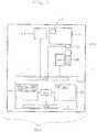
- Fig. 1shows an example of an analysis system 100.
- the analysis system 100comprises an analyzer 102.
- the analyzer 102comprises an analyzer controller 104, an analytical unit 106, a dispenser 112 for cartridge 110 and an identification unit 116. It can be seen that there is a biological sample 108 adjacent to the analytical unit 106.
- the analytical unit 106is operable or configured for obtaining an analysis result by performing a measurement on the biological sample 108.
- a cartridge 110is seen as being installed into the analyzer 102.
- the cartridge 110contains at least one reagent for analyzing the biological sample 108.
- the cartridge 110is shown as being in connection with a dispenser 112 for dispensing the at least one reagent into the biological sample 108.
- the cartridge 110also has an identifier 114. In different embodiments this could be a tag, a barcode, an RFID chip, or other parameter which can be measured. There is an identification unit 116 for measuring or obtaining the identifier 114 from the cartridge 110.
- the analytical unit 106, the dispenser 112, and the identification unit 116are all connected to a hardware interface 122 of the analyzer controller 104.
- the analyzer controller 104further comprises a processor 120.
- the processor 120is in communication with the hardware interface 122, a network interface 124, computer storage 128, and computer memory 130.
- the computer storage 128is shown as containing a cartridge database 132.
- the cartridge database 132contains information on cartridges with valid identifiers.
- the computer storage 128is shown as further containing an analysis protocol database 134.
- the analysis protocol database 134contains a set of analysis protocols which may be used by the analyzer 102 for analyzing the biological sample 108 for a particular cartridge. There may be a linking between the various cartridges in the cartridge database 132 and the analysis protocol database 134.
- the computer storage 128is shown as further containing an identifier 136.
- the identifier 136has been read from the identifier 114 and the cartridge 110 by the identification unit 116.
- the identifier 136may be checked against the cartridge database 132 to determine if a cartridge is valid or not. If it is valid then an associated analysis protocol is found in the analysis protocol database 134.
- Computer storage 128is further shown as containing a custom analysis protocol 138.
- the custom analysis protocol 138was constructed using the protocol creation system 150.
- the computer storage 128is further shown as containing an analysis result 140 that was measured by the analytical unit 106 from the biological sample 108.
- the computer memory 130is further shown as containing a control module 142.
- the control module 142enables the processor 120 to control the operation and function of the analyzer 102.
- the control module 142may use the analysis protocol to control the analytical unit 106 to acquire the analysis result 140.
- the analysis system 100is further shown as comprising a protocol creation system 150.
- the protocol creation system 150comprises a network interface 154. There is a network connection connecting the network interfaces 154 to 124.
- the protocol creation system 150further comprises a processor 152.
- the processor 152is in connection with the network interface 154, a user interface 158, computer storage 160 and computer memory 162.
- the computer storage 160is shown as containing analysis protocol parameters 164 that have been received from the user interface 158.
- the analysis protocol parameters 164were then used to create the custom analysis protocol 138 which is also shown as being stored in the computer storage 160.
- the custom analysis protocol 138was transferred via the network connection 156 to the analyzer controller 104.
- the computer memory 162is shown as containing analysis protocol creation module 166 which contains executable code which enables the processor 152 to create the custom analysis protocol 138 using the analysis protocol parameters 164.
- Fig. 2shows a flowchart which illustrates steps performed by the protocol creation system 150 of Fig. 1 .
- UCAPcustom analysis protocol
- Fig. 3shows a further example of an analysis system 300.
- the embodiment shown in Fig. 3is similar to that shown in Fig. 1 .
- the analyzer controller 104 and the protocol creation system 150 of Fig. 1have been combined into a single analyzer controller 104.
- the contents of the computer storages 128 and 160 in Fig. 1have been merged and the contents of the computer memory 130 and 162 have also been merged.
- the user interface 158 for entering the analysis protocol parameters 164is also now part of the analyzer controller 104.
- Fig. 4shows a further example of an analysis system 400.
- the analysis system 400is similar to the analysis system 300 shown in Fig. 3 .
- the identification tag 402may be used to create and/or program the identifier 114 on the cartridge 110.
- the identification tag generator 402may in some embodiments contain a barcode generator and/or an RFID chip programmer.
- Fig. 5shows a flowchart which illustrates a method.
- a cartridge with an invalid identifieris provided and the cartridge contains at least one reagent.
- a custom analysis protocol(UCAP) is generated.
- the custom analysis protocolis linked to the invalid identifier.
- the invalid identifierbecomes a valid identifier.
- the custom analysis protocolis transferred to an analyzer controller of an analyzer.
- the custom analysis protocolis selected.
- a cartridgeis loaded into the automatic analyzer.
- the identifieris read using an identification unit.
- the identifieris transferred to the analyzer controller, for example by a network connection.
- the identifier of the cartridgeis linked to the custom analysis protocol so the analyzer controller is thereby able to recall the custom analysis protocol for analyzing the biological sample.
- the biological sampleis analyzed using the at least one aliquot a reagent from the cartridge and this is done in accordance to the custom analysis protocol.
- Diagnostic laboratoriesneed a high flexibility to run their own assays on a fully integrated high throughput analytical system. For example laboratories may develop assays for varying flu epidemics.
- the present inventionmay provide for a utility channel workflow or UCW which allows the consumer to run their own assays on a system which reports sample pipetting from a primary/secondary tube, isolation of nucleic acids from samples, preparation of specific PCR-mixture, amplification and detection, calculation and export of intermediate results, reporting the results, and release of results to an LIS system.
- LISis a laboratory information system. Important aspects of the utility channel workflow are the definition and installation of customer defined assay parameters including cartridge IDs on the analytical system.
- Fig. 6shows a flow diagram which illustrates this process.
- the methodstarts with step 600.
- step 601a custom analysis protocol (UCAP) is.
- step 602a lot of one or more custom analysis protocol specific UCW cartridges are prepared.
- step 604a run is performed where a biological sample is measured.
- step 606is a decision box.
- the questionis to start a new run using the remaining UCW cartridges. If the answer is yes then step 604 is performed again. If not then the question proceeds to step 608 and the question is prepare a new lot of custom analysis protocol specific UCW cartridges. If the answer is yes then step 602 is performed again. If the answer is no then step 610 is performed which is also a question box.
- the questionis should the custom analysis protocol be updated. If the answer is yes then the method returns back to step 601. If no then the method ends in step 612.
- the important aspects of the utility channel workfloware the definition and installation of customer defined assay parameters including cartridgeIDs on the analytical system. This corresponds to step 601 in Fig. 6 .
- the appropriation of a customized cartridgecorresponds and the labeling of the customer cartridge with the cartridge corresponds to step 602 in Fig. 6 .
- the loading of the customized cartridge to run the customer defined assay on the systemcorresponds to step 604 in Fig. 6 .
- Fig. 7shows a flowchart which illustrates how to perform step 601 of Fig. 6 in greater detail. That is how to generate the custom analysis protocol.
- the custom analysis protocol or utility channel analysis packagecontains all the necessary assay parameters to perform the sample processing, amplification, detection and calculation of intermediate results.
- the operatorcan generate the custom analysis protocol using a UCW tool or utility channel tool which is a separate software on a consumer PC in some embodiments. After generating the custom analysis protocol the operator is able to save the custom analysis protocol for further modification or to export the custom analysis protocol from the UCW tool to the analytical system. This is demonstrated in Fig. 7 .
- First in step 700the method starts.
- step 702a custom analysis protocol for editing is provided.
- step 704the custom analysis protocol is modified.
- Step 706is a decision box and the question is should the custom analysis protocol be saved or published. If it is just saved then the method repeats the step 702. If it is decided to publish then the method proceeds to step 708. In step 708 the custom analysis protocol is installed on a analysis system. Finally in step 710 the custom analysis protocol is made available for testing. In step 704 the custom analysis protocol is modified.
- a few of the basic parameters which may be defined by the operatormay be the custom analysis protocol ID or identification which is equivalent to the identifier, the UCW cartridge ID. This identification may be used to link to the custom analysis protocol to an operator defined cartridge formulation.
- the operatormay also define the channel target assignment, the IC validity range, the sample type and sample processing input volume, the PCR profile and also possibly the calculation sensitivity.
- Fig. 8shows a flow diagram which illustrates the step 602 in Fig. 6 in greater detail.
- the flowchart in Fig. 8is broken into two parts.
- the first part 800shows the preparation of a custom analysis protocol specific cartridge .
- the second part 802illustrates the preparation of a customized PCR master mixture which is used in some embodiments.
- the methodstarts in step 804 with a generic utility channel cartridge and a PCR master mix reagent (MMX-R2) without primers and probe.
- Step 806is then performed from the section 802 of the flowchart.
- a generic MMX-R2 reagentis prepared.
- step 808take the generic MMX-R2 reagent and add 810 target specific primers and probe.
- the cartridgeis filled up to a final volume.
- the final MMX-R2is prepared.
- Step 804then proceeds to step 816, which receives the final MMX-R2 mixture prepared in step 814.
- the cartridgeis filled with the MMX-R2 into the utility channel cartridge.
- the utility channel cartridgeis relabeled.
- the utility channel cartridgeis ready for use.
- the UCWincludes the use of generic PCR master mixtures, MMX-R2 reagent which does not contain target specific primers, and a generic utility channel cartridge, based on the generic concept of the analytical system. The operator can prepare a custom analysis protocol specific cartridge by adding his target specific primers to the generic PCR master mixture and filling the customized PCR master mixture in the generic cartridge. This procedure is illustrated in Fig. 8 .
- Fig. 9shows a flowchart which illustrates the filling of the utility channel cartridge. This corresponds to part of step 602 in Fig. 6 .
- the UCW cartridgeIn order to use the custom analysis protocol specific cartridge in the fully integrated analytical system the UCW cartridge has to provide a corresponding identification tag to be recognized by the system.
- Two alternative labeling approachesare mentioned: first the UCW cartridge identifier will be written to an unprotected data area of the RFID or barcode and attached to the cassette using the UCW tool and a connected RFID or barcode writer. This is illustrated in Fig. 9 .
- First in step 900the filled UC reagent cassette is provided.
- the cartridgeis placed on an RFID reader and/or writer.
- step 904an appropriate published custom analysis protocol is selected using the UCW tool.
- step 906a write identifier is selected.
- step 904the UCW tool reads and verifies the RFID.
- Step 910is a decision box. The question is the cassette a UCW cartridge. If the answer is no then the cartridge RFID is unchanged and the method ends. If the answer is yes then a user defined reagent lot is entered in step 914.
- step 916the UCW tool is used to write the UCW cartridge name and lot to an RFID of the cartridge. Then finally in step 918 the UCW cartridge is ready for use.
- the unique identifier of the RFID chipcan be used as an identification tag.
- the unique identifier of the RFIDcan be linked with the corresponding custom analysis protocol via a cross table deposited on the analytical system.
- the cross tablethus comprises the protocol identifier which permits an invalid identifier to be changed into a valid identifier.
Landscapes
- General Health & Medical Sciences (AREA)
- Health & Medical Sciences (AREA)
- Immunology (AREA)
- Pathology (AREA)
- Analytical Chemistry (AREA)
- Biochemistry (AREA)
- Life Sciences & Earth Sciences (AREA)
- General Physics & Mathematics (AREA)
- Physics & Mathematics (AREA)
- Chemical & Material Sciences (AREA)
- Engineering & Computer Science (AREA)
- Epidemiology (AREA)
- Medical Informatics (AREA)
- Primary Health Care (AREA)
- Public Health (AREA)
- Automatic Analysis And Handling Materials Therefor (AREA)
Abstract
Description
- The invention relates to analysis systems for analyzing biological samples, in particular it relates to the creation of custom analysis protocols in fully automated analytical high throughput systems.
- Fully automated diagnostic analytical systems rely on validated assays and/or workflows. However in many situations, it would be beneficial if laboratories could specify custom assays for such fully automated diagnostic analyzer systems. For example to develop assays to detect emerging epidemics or for performing research studies.
- United States patent
US 8,035,485 discloses a system for automation of laboratory analyzers that utilizes radio frequency identification tags. - United States patent application
US 2009/0088336 A1 discloses a cartridge for automated detection on an analyte in a body fluid comprising: a sample collection unit configured to receive the bodily fluid sample, and array of assay units configured to receive a portion of the sample collection unit and run a chemical reaction that yields a detectible signal indicative of the presence of the analyte; an array of reagent units containing reagents for running the chemical reaction. - United States patent application
2008/0213872 A1 discloses cartridges which are inserted into the housing areas of flow-through automated instruments, which are equipped with sensors to ensure proper placement and usage of the cartridges. This application further discloses that cartridges may be identified with bar codes to prevent inserting the wrong cartridge or re-use of a cartridge and that a warning that the system may notify a user. - United States patent application
2011/0093249 A1 discloses a device which is also referred to as a cartridge. The device comprises a housing with location to accommodate assay units and reagent units. This application further discloses that many different sequences can be run for any chemical reaction to run on the device and that this may be done without changing the type of reagents in the cartridge. This application further discloses that the device may have an identifier that is detected or read by an identifier detector. - The invention provides for an analysis system and a method in the independent claims. Embodiments are given in the dependent claims.
- A controller as used herein encompasses a device, machine, or apparatus for controlling the operation and/or function of one or more other devices. Examples of a controller may include, but are not limited to: a computer, a processor, an embedded system or controller, a programmable logic controller, and a microcontroller. A 'computing device' or 'computer' as used herein encompasses to any device comprising a processor. A 'processor' as used herein encompasses an electronic component which is able to execute a program or machine executable instruction.
- A 'computer-readable storage medium' as used herein encompasses any tangible storage medium which may store instructions which are executable by a processor of a computing device. The computer-readable storage medium may be referred to as a computer-readable non-transitory storage medium.
- 'Computer memory' or 'memory' is an example of a computer-readable storage medium. Computer memory is any memory which is directly accessible to a processor or other controller. 'Computer storage' or 'storage' is an example of a computer-readable storage medium. Computer storage is any non-volatile computer-readable storage medium.
- A 'user interface' as used herein is an interface which allows a user or operator to interact with a computer or computer system.
- A 'hardware interface' as used herein encompasses a interface which enables a processor or other controller to interact with and/or control an external computing device and/or apparatus. A hardware interface may allow a processor to send control signals or instructions to an external computing device and/or apparatus. The hardware interface may enable the processor or other controller to receive sensor data and control the dispensing of the fluid. The hardware interface may be used to form a closed control loop in some embodiments.
- A 'biological sample' as used herein, refers to a material suspected of containing an analyte of interest. The sample can be derived from any biological source, such as a physiological fluid, including, blood, saliva, ocular lens fluid, cerebral spinal fluid, sweat, urine, milk, ascites fluid, mucous, synovial fluid, peritoneal fluid, amniotic fluid, tissue, cells or the like. The test sample can be pretreated prior to use, such as preparing plasma from blood, diluting viscous fluids, lysis or the like; methods of treatment can involve filtration, distillation, concentration, inactivation of interfering components, and the addition of reagents. A sample may be used directly as obtained from the source or following a pretreatment to modify the character of the sample, e.g. after being diluted with another solution or after having being mixed with reagents e.g. to carry out one or more diagnostic assays like e.g. clinical chemistry assays, immunoassays, coagulation assays, nucleic acid testing, and etc. The term "sample" as used herein is therefore not only used for the original sample but also relates to a sample which has already been processed (pipetted, diluted, mixed with reagents, enriched, having been purified, having been amplified etc). As used herein, the term "analyte" refers to the compound or composition in the biological sample to be detected or measured.
- The term 'reagent' is used to indicate a composition required for treatment of a sample. Reagents may be any liquid, e.g. a solvent or chemical solution, which needs to be mixed with a sample and/or other reagent in order e.g. for a reaction to occur, or to enable detection. A reagent may be for example a diluting liquid, including water, it may comprise an organic solvent, it may comprise a detergent, it may be a buffer. Reagents may also be dry reagents adapted e.g. to be dissolved by a sample, another reagent or a diluting liquid. A reagent in the more strict sense of the term may be a liquid solution containing a reactant, typically a compound or agent capable e.g. of binding to or chemically transforming one or more analytes present in a sample. Examples of reactants are enzymes, enzyme substrates, conjugated dyes, protein-binding molecules, nucleic acid binding molecules, antibodies, chelating agents, promoters, inhibitors, epitopes, antigens, and etc.
- In one aspect the invention provides for an analysis system for analyzing a biological sample. The analysis system comprises an analyzer. The analyzer comprises an analytical unit for analyzing the biological sample to obtain an analysis result. The analytical unit may perform a measurement on the biological sample to obtain the analysis result. As used herein an analyzer may also refer to multiple analyzers. Also an analytical unit may also refer to one or more analytical units. As such the analysis system may comprise more than one analyzer and each analyzer may comprise more than one analytical unit.
- The term 'measurement' relates to any type of measurement that can be performed on a biological sample following addition of at least one reagent, either directly or after processing of the biological sample. Processing of the biological sample may include isolating and/or purifying the analyte. In one embodiment, the reagents used for measurement may be analyte specific.
- The term 'analysis result' relates to the result of the analysis. The analysis result is obtained based on the measurement of the biological sample. The analysis result may be qualitative (the amount of analyte is above or below a threshold) or quatitative.
- The analyzer comprises an analyzer controller. The analyzer is operable or configured for receiving a cartridge comprising an identifier. An identifier is a property or label or tag which enables a cartridge to be identified as a specific cartridge or as a particular class of cartridge.
- In some embodiments the identifier may be a tag such as a barcode or RFID tag.
- In other embodiment the identifier may also comprise such properties as the dimensions or color of the cartridge. The cartridge contains at least one reagent for analyzing the biological sample. The analyzer comprises an identification unit for reading the identifier. The identification unit of course depends upon the type of identifier, for instance if the identifier is an RFID chip then the identification unit may comprise something for reading the RFID chip. Likewise, if the identifier comprises a barcode then the identification unit comprises a barcode reader. If the identifier is loaded to the shape or dimensions or color of the cartridge then the identification unit comprises an apparatus operable or configured for reading or measuring this property. The analyzer is operable or configured for receiving the cartridge.
- The analyzer is operable or configured for checking the validity of the identifier using the identification unit. The validity may for instance be compared or checked by comparing the for accepting the cartridge if the identifier is valid. The analyzer controller comprises a controller memory containing a set of analysis protocols. Each of the set of analysis protocols defines protocols and parameters for performing an analysis of the biological sample and is referenced by a protocol identifier.
- The term 'protocol' relates to the conditions in the analytical system to which the biological sample is subjected in order to obtain the analysis result.
- The term 'parameters' or 'protocol parameters' relates to the parameters defining a protocol.
- The analyzer controller is operable or configured for receiving the identifier from the identification unit. If the cartridge does not have a valid identifier then the analyzer may reject the use of the cartridge and not allow an analysis of the biological sample to be performed.
- The analysis system further comprises a protocol creation system comprising a processor. The protocol creation system further comprises a protocol creation system memory containing machine-executable instructions. The protocol creation system memory is computer memory or storage. Execution of the machine-executable instructions causes the processor to receive analysis protocol parameters from a user interface. For instance an operator may enter data or parameters into the user interface which are able to be used to generate the analysis protocol.
- Execution of the machine-executable instructions further cause the processor to generate a custom analysis protocol using the analysis protocol parameters. Execution of the instructions further causes the processor to link a custom analysis protocol to a protocol identifier. Execution of the machine-executable instructions further causes the processor to transfer the user created analysis protocol associated with the protocol identifier to the analyzer controller. The transfer of the user created analysis protocol associated with the protocol identifier to the analyzer controller then changes an invalid identifier of a specific cartridge into a valid identifier if the invalid identifier corresponds to the protocol identifier.
- The analyzer controller is operable or configured to append the custom analysis protocol to the set of analysis protocols.
- The analyzer controller accepts the cartridge comprising the now valid identifier which enables the biological sample to be processed according to the custom analysis protocol. This may be accomplished using the cartridge comprising the now valid identifier in the analyzer.
- This embodiment is advantageous because it enables the analyzer to load cartridges and perform custom analysis protocol that the analyzer would not be able to load. For instance many analysis systems used in laboratories have specific tests which are specified and certified. Their architecture prevents them from being used in a way which is not specified. Embodiments of the invention may provide for a convenient means of enabling custom cartridges and/or custom analysis protocols to be performed on such an analysis system.
- The term 'identifier' relates to an identifier of a cartridge as described herein.
- The term 'protocol identifier' relates to a identifier to which a protocol may be linked and which corresponds to an identifier of a cartridge.
- The transfer of the user created analysis protocol associated with the protocol identifier to the analyzer controller may be performed in a number of different ways. For instance in one embodiment the transfer may occur across a network.
- In another embodiment the user created analysis protocol may be written onto storage on a cartridge such as an RFID chip which is then transferred via the cartridge to the analyzer.
- In another embodiment the analyzer controller comprises a controller memory containing a set of analysis protocols.
- In another embodiment the analyzer controller comprises a controller memory containing a set of analysis protocols.
- In another embodiment the analyzer is configured for checking the validity of identifier using the identification unit by comparing the identifier to the set of analysis protocols. The analyzer is configured to accept the cartridge if the identifier is valid. The analyzer is configured to reject the cartridge if the identifier is invalid. The analyzer may determine if the identifier is valid or invalid by checking so see if the identifier is one of or is listed in the set of analysis protocols. If the identifier is one of the set of analysis protocols then it is valid. If the identifier is not one of the set of analysis protocols then it is invalid.
- In another embodiment execution of the instructions cause the processor to change an invalid identifier on the cartridge into a valid identifier by appending the user created analysis protocol associated with the protocol identifier to the set of analysis protocols in the analyzer controller. In some cases this may be done if the invalid identifier corresponds to the protocol identifier. This may then result in the analyzer controller accepting the now valid identifier which permits the biological sample to be processed according to the custom analysis protocol using the cartridge comprising valid identifier in the analyzer. This has turned an invalid identifier into a valid identifier.
- The combination of the above mentioned embodiments may provide for a means of expanding the functionality of an analysis system which comprises an analytical unit and controls the selection of analysis protocols with an identifier on a cartridge filled with a reagent
- In another embodiment a data carrier such as a computer-readable storage medium such as a contact disc or USB stick may have the analysis protocol written to it. An operator may then later transfer it to the analyzer.
- In a further embodiment the analyzer and the protocol creation system are integrated into a single computer or computer system. In this case the transfer may occur by transferring data between the programs or by running a data file to the storage on the analyzer controller.
- In another embodiment the protocol creation system is operably linked to the analyzer controller. Operably linked as used herein encompasses the ability between the protocol system and the analyzer controller to share data or functionality and enables them to be operated in conjunction with one another. For instance there may be a network connection between the protocol creation system and the analyzer controller.
- In another embodiment the identifier comprises an identification tag. The identification unit comprises an identification tag reader. In this embodiment a tag of some sort is installed or attached onto the cartridge. The identification unit then at least partially uses the identification tag reader to read the identifier from the identification tag.
- In another embodiment the identification tag comprises an RFID tag. In this case the identification unit would comprise an RFID reader.
- In another embodiment the identifier is a unique identifier.
- In another embodiment the protocol creation system comprises identification tag generator for generating a custom identification tag. The identification tag generator may for instance be a system producing a tag which may be attached to the cartridge. In other instances the identification tag generator is a system for modifying an existing tag. For instance the cartridge may comprise an RFID chip which is simply programmed by the identification tag generator. Execution of the machine-executable instructions further causes the processor to generate a custom identification tag comprising an identifier before linking the custom analysis protocol to the identifier.
- In another embodiment the custom identification tag comprises an RFID tag. The identification tag generator comprises a first RFID interface. The protocol creation system is operable or configured for writing RFID data to the RFID tag using the first RFID interface. The identification tag reader comprises a second RFID interface. The analyzer controller is operable or configured for determining the identifier at least partially by reading the RFID data using the second RFID interface.
- In another embodiment the identification tag generator is operable or configured for writing the RFID data to the RFID tag via a first cryptographic data exchange. The identification tag reader is operable or configured for reading the RFID tag via a second cryptographic data exchange. For instance a public key pair or an encryption key which is shared between the analysis system and the protocol creation system may be used to securely read and write data from the RFID tag. This may have the benefit of preventing someone from producing an unauthorized cartridge or custom analysis protocol.
- The cryptographic data exchange could be performed in a variety of ways, for example the protocol creation system could generate a symmetric key that is used to encrypt the RFID data and then transmit the symmetric key to the analyzer. In another example the workflow manager generates a public key pair or uses a pre-existing key pair for the RFID tag which is then used to encrypt the data. The analyzer controller and the RFID chip use each other's public key to exchange data. In another example a key exchange is done. For example a Diffie-Hellman algorithm is used to exchange keys securely and then they use their keys to communicate securely via the RFID chip.
- In another embodiment the RFID data comprises analysis protocol modification data. Analysis protocol modification data as used herein encompasses data which may be used to generate or modify an analysis protocol. For instance the custom analysis protocol could be stored on the RFID chip. In some embodiments the use of the first and second cryptographic data exchange may be used to verify that the protocol modification data on the RFID tag or chip is indeed valid and is allowed to create a custom analysis protocol on the analyzer.
- In another embodiment the identifier is determined as least partially using the unique identifier.
- In another embodiment the analyzer is an automated nucleic acid analyzer system.
- In another embodiment the analysis system protocol parameters comprise any one of the following: an analysis protocol identifier, an identifier, a channel target assignment, an internal control validity range, a sample type, a sample process input volume, a polymerase chain reaction profile, a calculation sensitivity, dilution factors, incubation time, reagent addition, volumes, temperature settings, washing steps and combinations thereof.
- The advantage of the system and method described herein is that it allows the operator to run custom made assays on a fully automated and validated analytical system. The present invention allows the operator to run custom made assays on a validated high throughput analytical system which supports sample pipetting from primary/secondary tubes, analyte isolation, preparation of analyte specific reagents, measurement and calculation to obtain an analysis result. The analytical system and method described herein also provide increased flexibility and optimized throughput which make it possible to react to seasonal or new occurrences of infectious diseases to which no validated assay reagents are offered for a specific high throughput system.
A further advantage is that the operator can use validated reagents which lack the analyte specific components to prepare the analyte specific reagents. This optimized the quality of the custom made analyte specific reagents and, thus, also optimizes the quality of the analysis results obtained by the operator. - In another embodiment the analyzer is an immunoassay analyzer or a coagulation analyzer or a nucleic acid analyzer.
- The advantage of the present invention is that it allows the operator to run custom made assays on a fully automated and validated analytical system. The present invention allows the operator to run custom made assays on an analytical and fully integrated nucleic acid testing system which supports sample pipetting from primary/secondary tubes, nucleic acid isolation, preparation of specific amplification reagents, amplification and detection, calculation and export of intermediate results, reporting of analysis results and release of analysis results to an LIS and/or HIS system.
- The term "amplification" generally refers to the production of a plurality of nucleic acid molecules from a target nucleic acid wherein primers hybridize to specific sites on the target nucleic acid molecules in order to provide an inititation site for extension by a polymerase. Amplification can be carried out by any method generally known in the art, such as but not limited to: standard PCR, long PCR, hot start PCR, qPCR, RT-PCR, real time PCR and Isothermal Amplification such as 3SR, NASBA or TMA/TAA.
- In another embodiment the identifier uniquely identifies a particular cartridge.
- In another embodiment the identifier of the cartridge uniquely identifies a particular cartridge.
- In another embodiment the identifier of the cartridge uniquely identifies the cartridge.
- In another embodiment the identifier specifies a chosen analysis protocol. The chosen analysis protocol is one of the set of analysis protocols.
- In another embodiment the custom identification tag comprises a barcode. The identification tag generally comprises a barcode printer. The identification tag reader comprises a barcode reader. The analyzer controller is operable or configured for determining the identifier at least partially from the barcode.
- In another embodiment the analytical system further comprises the cartridge.
- In another embodiment the cartridge comprises the identifier and also contains at least one reagent for analyzing the biological sample.
- In another embodiment the at least one reagent comprises an assay specific reagent provided by an operator. In some embodiments the assay specific target reagent is provided by the operator and may be added to an empty cartridge by the operator. The cartridge may also further contain reagents which are not assay specific, that is they may be used for any assay also assays which are not specific for the used program by the operator.
- Some specific examples of assay specific reagents are specific oligonucleotides for amplifying and/or detecting a target nucleic acid. They may also be specific antibodies but may also be other reagents used in the special assay such as enzymes, a cation or a detergent.
- In another embodiment the analysis system further comprises a network connection for exchanging analysis protocol data between the protocol creation system and the analysis controller. Execution of the machine-executable instructions causes the processor to transfer the user created analysis protocol to the analyzer using the network connection.
- In another aspect the invention provides for a method of analyzing a biological sample in an automated analysis system comprising an analyzer. The analyzer is operable or configured for accepting a cartridge with a valid identifier and rejecting a cartridge with an invalid identifier. The method comprises the step of providing a cartridge comprising an invalid identifier and containing at least one reagent for analyzing the biological sample. The method further comprises the step of generating a custom analysis protocol with a protocol creation system. The method further comprises the step of linking the custom analysis protocol to a protocol identifier corresponding to the invalid identifier. The method further comprises the step of transferring the custom analysis protocol with the protocol identifier from the protocol creation system to an analyzer controller of the analyzer, thereby changing the invalid identifier on the cartridge into a valid identifier.
- The analyzer controller permits the analyzer to accept the cartridge with the now valid identifier. The method further comprises the step of selecting the custom analysis protocol linked to the protocol identifier corresponding to the now valid identifier. The method further comprises the step of loading the cartridge with the now valid identifier into the automated analyzer. The method further comprises the step of reading the identifier. The identifier is read by an identification unit. The analyzer comprises the identification unit. The method further comprises the step of analyzing the biological sample using at least one aliquot of said at least one reagent comprised in said cartridge according to the selected custom analysis protocol. It should be noted that the steps of providing the cartridge comprising an invalid identifier and containing at least one reagent for analyzing the biological sample and generating a custom analysis protocol with a protocol creation system are interchangeable and may be performed in parallel.
- The term 'aliquot of a reagent' relates to portions of a reagent which are employed for testing of a biological sample. Aliquots are typically generated by pipetting a portion of a reagent into a tube or cuvette or well where then further treatment is conducted. When two or more aliquots of a reagent are needed it is for example possible to aspirate a volume of that reagent and to discharge portions of that volume into two or more wells. The term reagent aliquot is intended to cover also reagent aliquots mixed with biological samples and other fluids as it is typically necessary for assaying the biological samples.
- In another embodiment the identifier comprises an identification tag.
- In another embodiment the identifier is a unique identifier on the identification tag. The controller memory comprises a cross table comprising protocol identifiers corresponding to unique identifiers which assigns the unique identifier to the analysis protocol.
- In another embodiment the identifier is generated on an identification tag by an identifier generator and the custom analysis protocol is stored with a reference to the protocol identifier. In another embodiment the step of generating the custom analysis protocol with a protocol creation system comprises receiving analysis protocol parameters from the user interface, generating said custom analysis protocol using the analysis protocol parameters and linking the custom analysis protocol to a protocol identifier.
- In another embodiment the custom analysis protocol is created on a protocol creation system. The custom created analysis protocol is transferred from the analysis protocol creation system to the analyzer controller using a network connection. The custom analysis protocol is referenced by the protocol identifier.
- In another embodiment the method further comprises adding at least one reagent to the cartridge prior to providing the cartridge comprising invalid identifier and containing at least one reagent for analyzing the biological sample.
- In another embodiment the steps of transferring said custom analysis protocol associated with the protocol identifier from the protocol creation system to an analyzer controller of the analyzer to the step of transferring the identifier to said analyzer controller are fully automated.
- In another embodiment the at least one reagent comprises oligonucleotides specific for a target nucleic acid.
- It is understood that one or more of the aforementioned embodiments of the invention may be combined as long as the combined embodiments are not mutually exclusive.
- In the following embodiments of the invention are explained in greater detail, by way of example only, making reference to the drawings in which:
Fig. 1 shows an example of an analysis system with a protocol creation system;Fig. 2 shows a flowchart which illustrates steps performed by the protocol creation system ofFig. 1 ;Fig. 3 shows a further example of an analysis system;Fig. 4 shows a further example of an analysis system;Fig. 5 shows a flowchart which illustrates a method;Fig. 6 shows a method of developing a custom utility channel workflow;Fig. 7 shows a flowchart which illustrates how to performstep 601 ofFig. 6 ;Fig. 8 shows a flow diagram which illustratesstep 602 ofFig. 6 in greater detail; andFig. 9 shows a flowchart which illustrates the creation of custom utility channel cartridges .- Like numbered elements in these figures are either equivalent elements or perform the same function. Elements which have been discussed previously will not necessarily be discussed in later figures if the function is equivalent.
Fig. 1 shows an example of ananalysis system 100. Theanalysis system 100 comprises ananalyzer 102. Theanalyzer 102 comprises ananalyzer controller 104, ananalytical unit 106, adispenser 112 forcartridge 110 and anidentification unit 116. It can be seen that there is abiological sample 108 adjacent to theanalytical unit 106. Theanalytical unit 106 is operable or configured for obtaining an analysis result by performing a measurement on thebiological sample 108. Acartridge 110 is seen as being installed into theanalyzer 102. Thecartridge 110 contains at least one reagent for analyzing thebiological sample 108. Thecartridge 110 is shown as being in connection with adispenser 112 for dispensing the at least one reagent into thebiological sample 108.- The
cartridge 110 also has anidentifier 114. In different embodiments this could be a tag, a barcode, an RFID chip, or other parameter which can be measured. There is anidentification unit 116 for measuring or obtaining theidentifier 114 from thecartridge 110. Theanalytical unit 106, thedispenser 112, and theidentification unit 116 are all connected to ahardware interface 122 of theanalyzer controller 104. Theanalyzer controller 104 further comprises aprocessor 120. Theprocessor 120 is in communication with thehardware interface 122, anetwork interface 124,computer storage 128, andcomputer memory 130. Thecomputer storage 128 is shown as containing acartridge database 132. - The
cartridge database 132 contains information on cartridges with valid identifiers. Thecomputer storage 128 is shown as further containing ananalysis protocol database 134. Theanalysis protocol database 134 contains a set of analysis protocols which may be used by theanalyzer 102 for analyzing thebiological sample 108 for a particular cartridge. There may be a linking between the various cartridges in thecartridge database 132 and theanalysis protocol database 134. Thecomputer storage 128 is shown as further containing anidentifier 136. Theidentifier 136 has been read from theidentifier 114 and thecartridge 110 by theidentification unit 116. Theidentifier 136 may be checked against thecartridge database 132 to determine if a cartridge is valid or not. If it is valid then an associated analysis protocol is found in theanalysis protocol database 134. Computer storage 128 is further shown as containing acustom analysis protocol 138. Thecustom analysis protocol 138 was constructed using theprotocol creation system 150. Thecomputer storage 128 is further shown as containing ananalysis result 140 that was measured by theanalytical unit 106 from thebiological sample 108.- The
computer memory 130 is further shown as containing acontrol module 142. Thecontrol module 142 enables theprocessor 120 to control the operation and function of theanalyzer 102. In particular thecontrol module 142 may use the analysis protocol to control theanalytical unit 106 to acquire theanalysis result 140. - The
analysis system 100 is further shown as comprising aprotocol creation system 150. Theprotocol creation system 150 comprises anetwork interface 154. There is a network connection connecting the network interfaces 154 to 124. Theprotocol creation system 150 further comprises aprocessor 152. Theprocessor 152 is in connection with thenetwork interface 154, auser interface 158,computer storage 160 andcomputer memory 162. Thecomputer storage 160 is shown as containinganalysis protocol parameters 164 that have been received from theuser interface 158. Theanalysis protocol parameters 164 were then used to create thecustom analysis protocol 138 which is also shown as being stored in thecomputer storage 160. Thecustom analysis protocol 138 was transferred via thenetwork connection 156 to theanalyzer controller 104. Thecomputer memory 162 is shown as containing analysisprotocol creation module 166 which contains executable code which enables theprocessor 152 to create thecustom analysis protocol 138 using theanalysis protocol parameters 164. Fig. 2 shows a flowchart which illustrates steps performed by theprotocol creation system 150 ofFig. 1 . First instep 200 the analysis protocol parameters are received from the user interface.- Next in step 204 a custom analysis protocol (UCAP) is generated using the analysis protocol parameters. Then in step 206 a link between a custom analysis protocol and the protocol identifier is formed. Finally in step 208 the user created protocol associated with the protocol identifier is transferred to the analyzer controller.
Fig. 3 shows a further example of ananalysis system 300. The embodiment shown inFig. 3 is similar to that shown inFig. 1 . However, in this case theanalyzer controller 104 and theprotocol creation system 150 ofFig. 1 have been combined into asingle analyzer controller 104. The contents of thecomputer storages Fig. 1 have been merged and the contents of thecomputer memory user interface 158 for entering theanalysis protocol parameters 164 is also now part of theanalyzer controller 104.Fig. 4 shows a further example of ananalysis system 400. Theanalysis system 400 is similar to theanalysis system 300 shown inFig. 3 . However, inFig. 4 there is additionally anidentification tag generator 402. Theidentification tag 402 may be used to create and/or program theidentifier 114 on thecartridge 110. For instance theidentification tag generator 402 may in some embodiments contain a barcode generator and/or an RFID chip programmer.Fig. 5 shows a flowchart which illustrates a method. First in step 500 a cartridge with an invalid identifier is provided and the cartridge contains at least one reagent. Next in step 502 a custom analysis protocol (UCAP) is generated. Then instep 504 the custom analysis protocol is linked to the invalid identifier. At this point the invalid identifier becomes a valid identifier. Whenever the identifier is encountered by an analysis system the analysis protocol will be recalled and may be used to analyze a biological sample. Next instep 506 the custom analysis protocol is transferred to an analyzer controller of an analyzer. Optionally, instep 508 the custom analysis protocol is selected. Next in step 510 a cartridge is loaded into the automatic analyzer. In step 512 the identifier is read using an identification unit. In some embodiments the identifier is transferred to the analyzer controller, for example by a network connection. The identifier of the cartridge is linked to the custom analysis protocol so the analyzer controller is thereby able to recall the custom analysis protocol for analyzing the biological sample. Finally instep 514 the biological sample is analyzed using the at least one aliquot a reagent from the cartridge and this is done in accordance to the custom analysis protocol.- Diagnostic laboratories need a high flexibility to run their own assays on a fully integrated high throughput analytical system. For example laboratories may develop assays for varying flu epidemics. The present invention may provide for a utility channel workflow or UCW which allows the consumer to run their own assays on a system which reports sample pipetting from a primary/secondary tube, isolation of nucleic acids from samples, preparation of specific PCR-mixture, amplification and detection, calculation and export of intermediate results, reporting the results, and release of results to an LIS system. LIS is a laboratory information system. Important aspects of the utility channel workflow are the definition and installation of customer defined assay parameters including cartridge IDs on the analytical system.
Fig. 6 shows a flow diagram which illustrates this process. First the method starts withstep 600. Next in step 601 a custom analysis protocol (UCAP) is. Next in step 602 a lot of one or more custom analysis protocol specific UCW cartridges are prepared. Then in step 604 a run is performed where a biological sample is measured. Instep 606 is a decision box. The question is to start a new run using the remaining UCW cartridges. If the answer is yes then step 604 is performed again. If not then the question proceeds to step 608 and the question is prepare a new lot of custom analysis protocol specific UCW cartridges. If the answer is yes then step 602 is performed again. If the answer is no then step 610 is performed which is also a question box. The question is should the custom analysis protocol be updated. If the answer is yes then the method returns back to step 601. If no then the method ends instep 612.- The important aspects of the utility channel workflow are the definition and installation of customer defined assay parameters including cartridgeIDs on the analytical system. This corresponds to step 601 in
Fig. 6 . The appropriation of a customized cartridge corresponds and the labeling of the customer cartridge with the cartridge corresponds to step 602 inFig. 6 . The loading of the customized cartridge to run the customer defined assay on the system corresponds to step 604 inFig. 6 . Fig. 7 shows a flowchart which illustrates how to performstep 601 ofFig. 6 in greater detail. That is how to generate the custom analysis protocol. The custom analysis protocol or utility channel analysis package contains all the necessary assay parameters to perform the sample processing, amplification, detection and calculation of intermediate results. The operator can generate the custom analysis protocol using a UCW tool or utility channel tool which is a separate software on a consumer PC in some embodiments. After generating the custom analysis protocol the operator is able to save the custom analysis protocol for further modification or to export the custom analysis protocol from the UCW tool to the analytical system. This is demonstrated inFig. 7 . First instep 700 the method starts. Next in step 702 a custom analysis protocol for editing is provided. Next instep 704 the custom analysis protocol is modified. Step 706 is a decision box and the question is should the custom analysis protocol be saved or published. If it is just saved then the method repeats thestep 702. If it is decided to publish then the method proceeds to step 708. Instep 708 the custom analysis protocol is installed on a analysis system. Finally instep 710 the custom analysis protocol is made available for testing. Instep 704 the custom analysis protocol is modified.- A few of the basic parameters which may be defined by the operator may be the custom analysis protocol ID or identification which is equivalent to the identifier, the UCW cartridge ID. This identification may be used to link to the custom analysis protocol to an operator defined cartridge formulation. The operator may also define the channel target assignment, the IC validity range, the sample type and sample processing input volume, the PCR profile and also possibly the calculation sensitivity.
Fig. 8 shows a flow diagram which illustrates thestep 602 inFig. 6 in greater detail. The flowchart inFig. 8 is broken into two parts. Thefirst part 800 shows the preparation of a custom analysis protocol specific cartridge . Thesecond part 802 illustrates the preparation of a customized PCR master mixture which is used in some embodiments. The method starts instep 804 with a generic utility channel cartridge and a PCR master mix reagent (MMX-R2) without primers and probe. Step 806 is then performed from thesection 802 of the flowchart. In step 806 a generic MMX-R2 reagent is prepared. Next instep 808 take the generic MMX-R2 reagent and add 810 target specific primers and probe. Instep 812 the cartridge is filled up to a final volume. In the final step 814 the final MMX-R2 is prepared. Step 804 then proceeds to step 816, which receives the final MMX-R2 mixture prepared in step 814.- Next in
step 818 the cartridge is filled with the MMX-R2 into the utility channel cartridge. Next instep 820 the utility channel cartridge is relabeled. Finally instep 822 the utility channel cartridge is ready for use. Essentially the UCW includes the use of generic PCR master mixtures, MMX-R2 reagent which does not contain target specific primers, and a generic utility channel cartridge, based on the generic concept of the analytical system. The operator can prepare a custom analysis protocol specific cartridge by adding his target specific primers to the generic PCR master mixture and filling the customized PCR master mixture in the generic cartridge. This procedure is illustrated inFig. 8 . Fig. 9 shows a flowchart which illustrates the filling of the utility channel cartridge. This corresponds to part ofstep 602 inFig. 6 . In order to use the custom analysis protocol specific cartridge in the fully integrated analytical system the UCW cartridge has to provide a corresponding identification tag to be recognized by the system. Two alternative labeling approaches are mentioned: first the UCW cartridge identifier will be written to an unprotected data area of the RFID or barcode and attached to the cassette using the UCW tool and a connected RFID or barcode writer. This is illustrated inFig. 9 . First instep 900 the filled UC reagent cassette is provided. Next instep 902 the cartridge is placed on an RFID reader and/or writer.- Next in step 904 an appropriate published custom analysis protocol is selected using the UCW tool. Next in step 906 a write identifier is selected. Next in step 904 the UCW tool reads and verifies the RFID. Step 910 is a decision box. The question is the cassette a UCW cartridge. If the answer is no then the cartridge RFID is unchanged and the method ends. If the answer is yes then a user defined reagent lot is entered in
step 914. Next in step 916 the UCW tool is used to write the UCW cartridge name and lot to an RFID of the cartridge. Then finally instep 918 the UCW cartridge is ready for use. - Alternatively the unique identifier of the RFID chip can be used as an identification tag. The unique identifier of the RFID can be linked with the corresponding custom analysis protocol via a cross table deposited on the analytical system. The cross table, thus comprises the protocol identifier which permits an invalid identifier to be changed into a valid identifier. Finally when performing a run using the utility channel is similar to the standard workflow. The operator can load the analytical system with the custom analysis protocol specific cartridge, which is used in the same way that a cartridge containing a manufacturer provided assay. The UCW w uses the same bulk reagents and consumables.
- 100
- analysis system
- 102
- analyzer
- 104
- analyzer controller
- 106
- analytical unit
- 108
- biological sample
- 110
- cartridge
- 112
- dispenser
- 114
- identifier
- 116
- identification unit
- 120
- processor
- 122
- hardware interface
- 124
- network interface
- 128
- computer storage
- 130
- computer memory
- 132
- cartridge database
- 134
- analysis protocol database
- 136
- identifier
- 138
- custom analysis protocol
- 140
- analysis result
- 142
- control module
- 150
- protocol creation system
- 152
- processor
- 154
- network interface
- 156
- network connection
- 158
- user interface
- 160
- computer storage
- 162
- computer memory
- 164
- analysis protocol parameters
- 166
- analysis protocol creation module
- 300
- analysis system
- 400
- analysis system
- 402
- identification tag generator
Claims (15)
- A method of analyzing a biological sample (108) in a fully automated and validated analysis system (100, 300, 400) comprising an analyzer (102), comprising the steps of:a) providing (500) a cartridge (110) comprising an invalid identifier and containing at least one reagent for analyzing the biological sample;b) generating (502) a custom analysis protocol (138) with a protocol creation system (150), wherein steps a) and b) are interchangeable or may be performed in parallel;c) linking (504) the custom analysis protocol (138) to a protocol identifier corresponding to the invalid identifier;d) changing the invalid identifier into a valid identifier by transferring (506) said custom analysis protocol (138) associated with the protocol identifier from the protocol creation system (150) to a set of analysis protocols (134) stored by an analyzer controller (104) of the analyzer (102), wherein the analyzer controller (104) comprises a controller memory (128) containing the set of analysis protocols (134), wherein each of the set of analysis protocols (134) defines protocols and parameters for performing the analysis of a biological sample and is referenced by a protocol identifier, and wherein said analyzer controller (104) permits the analyzer (102) to load into the analyzer (100, 300. 400) and accept the cartridge (110) if the invalid identifier corresponds to the protocol identifier by comparing the identifier to the set of analysis protocols (134);e) selecting said custom analysis protocol (138) linked to the protocol identifier corresponding to the now valid identifier,f) loading (508) said cartridge (110) with said now valid identifier into said analyzer (102);g) reading (510) said identifier, wherein the identifier is read by an identification unit (116) comprising an identifier reader comprised in the analyzer (102);
andh) analyzing (514) said biological sample using at least one aliquot of said at least one reagent comprised in said cartridge (110) according to the selected custom analysis protocol (138). - The method of claim 1, wherein the identifier is comprised on an identification tag.
- The method of claim 1, wherein the identifier is a unique identifier on the identification tag, and the controller memory (128) comprises a cross-table comprising protocol identifiers corresponding to unique identifiers which assigns a unique identifier to an analysis protocol.
- The method of claim 2, wherein the identifier is generated on an identification tag by an identification tag generator (402) and the custom analysis protocol (138) is stored with a reference to the protocol identifier.
- The method of claim 1, wherein said generating a custom analysis protocol (138) in step b) comprises:- receiving (200) analysis protocol parameters (164) from a user interface (158);- generating (202) said custom analysis protocol (138) using the analysis protocol parameters (164); and- linking (204) the custom analysis protocol (138) to a protocol identifier.
- The method of any one of claims 1 to 5, wherein said custom analysis protocol (138) is created on the protocol creation system (150), and wherein the custom analysis protocol (138) is transferred from the protocol creation system (150) to the analyzer controller (104) using a network connection (156), wherein the custom analysis protocol (138) is referenced by the protocol identifier.
- A fully automated and validated analysis system (100, 300, 400) for analyzing a biological sample (108) according to the method of any of the claims 1 to 6.
- The fully automated and validated analysis system (100, 300, 400) of claim 7: comprising:- a cartridge (110) comprising an identifier (114) and containing at least one reagent for analyzing the biological sample;- an analyzer (102),wherein the analyzer (102) comprises an analytical unit (106) for analyzing the biological sample to obtain an analysis result (140),wherein the analyzer (102) comprises an analyzer controller (104),wherein the analyzer (102) comprises an identification unit (116) for reading the identifier,wherein the analyzer controller (104) comprises a controller memory (128) containing a set of analysis protocols (134),wherein the analyzer controller (104) is configured for receiving the identifier from the identification unit (116),- a protocol creation system (150, 104) comprising a processor (152),
wherein the protocol creation system (150) further comprises a protocol creation system memory (162) containing machine executable instructions (166);- wherein execution of the machine executable instructions (166) causes the processor (152) to:• receive (200) analysis protocol parameters (164) from a user interface (158);• generate (202) a custom analysis protocol (138) using the analysis protocol parameters (164) ;• link (204) the custom analysis protocol (138) to a protocol identifier, and• change an invalid identifier on the cartridge (110) into a valid identifier by appending (206) the custom analysis protocol (138) associated with the protocol identifier to the set of analysis protocols (134) in the analyzer controller (104) if the invalid identifier corresponds to the protocol identifier. - The fully automated and validated analysis system (100, 300, 400) of claim 8, wherein the protocol creation system (150) is operably linked (156) to the analyzer controller (104).
- The fully automated and validated analysis system (100, 300, 400) of any one of claims 7 to 9, wherein the identification unit (116) comprises an identification tag reader configured for reading an identification tag comprising the identifier.
- The fully automated and validated analysis system (100, 300, 400) of any one of any one of the claims 7 to 10, wherein said protocol creation system (150) comprises an identification tag generator (402) for generating a custom identification tag, and wherein the execution of the machine executable instructions (166) causes the processor (152) to generate a custom identification tag comprising a custom identifier before linking the custom analysis protocol (138) to the identifier.
- The fully automated and validated analysis system (100, 300, 400) of any one of the claims 7 to 11, wherein the analysis protocol parameters (164) comprise any one of the following: an analysis protocol identifier, a cartridge identifier, a channel target assignment, an internal control validity range, a sample type, a sample process input volume, a polymerase chain reaction profile, a calculation sensitivity, dilution factors, incubation time, reagent addition, volumes, temperature settings, washing steps and combinations thereof.
- The fully automated and validated analysis system (100, 300, 400) of any one of the claims 7 to 12, wherein the identifier of the cartridge (110) uniquely identifies the cartridge (110).
- The fully automated and validated analysis system (100, 300, 400) of any one of the claims 7 to 13, wherein the at least one reagent comprises an assay specific reagent provided by the operator.
- The fully automated and validated analysis system (100, 300, 400) according to any one of the claims 7 to 14, wherein the analysis system further comprises a network connection (156) for exchanging analysis protocol data between the protocol creation system (150) and the analyzer controller (104), and wherein the execution of the machine executable instructions causes the processor (152) to transfer the custom analysis protocol (138) to the analyzer (102) using the network connection (156).
Priority Applications (1)
| Application Number | Priority Date | Filing Date | Title |
|---|---|---|---|
| EP24151414.0AEP4332978B1 (en) | 2013-04-05 | 2014-03-14 | Analysis method for a biological sample |
Applications Claiming Priority (2)
| Application Number | Priority Date | Filing Date | Title |
|---|---|---|---|
| EP13162469 | 2013-04-05 | ||
| EP14160085.8AEP2787352A1 (en) | 2013-04-05 | 2014-03-14 | Analysis system for a biological sample |
Related Parent Applications (1)
| Application Number | Title | Priority Date | Filing Date |
|---|---|---|---|
| EP14160085.8ADivisionEP2787352A1 (en) | 2013-04-05 | 2014-03-14 | Analysis system for a biological sample |
Related Child Applications (2)
| Application Number | Title | Priority Date | Filing Date |
|---|---|---|---|
| EP24151414.0ADivisionEP4332978B1 (en) | 2013-04-05 | 2014-03-14 | Analysis method for a biological sample |
| EP24151414.0ADivision-IntoEP4332978B1 (en) | 2013-04-05 | 2014-03-14 | Analysis method for a biological sample |
Publications (2)
| Publication Number | Publication Date |
|---|---|
| EP3570040A1true EP3570040A1 (en) | 2019-11-20 |
| EP3570040B1 EP3570040B1 (en) | 2024-02-14 |
Family
ID=48095587
Family Applications (3)
| Application Number | Title | Priority Date | Filing Date |
|---|---|---|---|
| EP24151414.0AActiveEP4332978B1 (en) | 2013-04-05 | 2014-03-14 | Analysis method for a biological sample |
| EP19175073.6AActiveEP3570040B1 (en) | 2013-04-05 | 2014-03-14 | Analysis method for a biological sample |
| EP14160085.8AWithdrawnEP2787352A1 (en) | 2013-04-05 | 2014-03-14 | Analysis system for a biological sample |
Family Applications Before (1)
| Application Number | Title | Priority Date | Filing Date |
|---|---|---|---|
| EP24151414.0AActiveEP4332978B1 (en) | 2013-04-05 | 2014-03-14 | Analysis method for a biological sample |
Family Applications After (1)
| Application Number | Title | Priority Date | Filing Date |
|---|---|---|---|
| EP14160085.8AWithdrawnEP2787352A1 (en) | 2013-04-05 | 2014-03-14 | Analysis system for a biological sample |
Country Status (5)
| Country | Link |
|---|---|
| US (1) | US10416177B2 (en) |
| EP (3) | EP4332978B1 (en) |
| JP (2) | JP6671833B2 (en) |
| CN (2) | CN112597782B (en) |
| CA (1) | CA2847765C (en) |
Families Citing this family (32)
| Publication number | Priority date | Publication date | Assignee | Title |
|---|---|---|---|---|
| US9524372B2 (en) | 2011-09-09 | 2016-12-20 | Alverix, Inc. | In-vitro diagnostic device using external information in conjunction with test results |
| US9715579B2 (en) | 2011-09-09 | 2017-07-25 | Alverix, Inc. | Distributed network of in-vitro diagnostic devices |
| JP1628116S (en) | 2012-10-24 | 2019-04-01 | ||
| US20140322706A1 (en) | 2012-10-24 | 2014-10-30 | Jon Faiz Kayyem | Integrated multipelx target analysis |
| CN107866286A (en) | 2013-03-15 | 2018-04-03 | 金马克诊断股份有限公司 | Systems, methods, and apparatus for manipulating deformable fluid containers |
| US9498778B2 (en) | 2014-11-11 | 2016-11-22 | Genmark Diagnostics, Inc. | Instrument for processing cartridge for performing assays in a closed sample preparation and reaction system |
| USD881409S1 (en) | 2013-10-24 | 2020-04-14 | Genmark Diagnostics, Inc. | Biochip cartridge |
| JP5886482B1 (en)* | 2014-06-09 | 2016-03-16 | 国立研究開発法人産業技術総合研究所 | Protocol chart creating apparatus, protocol chart creating method, computer program, and protocol chart |
| MX2017008721A (en) | 2014-12-31 | 2017-11-17 | Lantheus Medical Imaging Inc | Lipid-encapsulated gas microsphere compositions and related methods. |
| WO2016130964A1 (en) | 2015-02-13 | 2016-08-18 | Abbott Laboratories | Decapping and capping apparatus, systems and methods for use in diagnostic analyzers |
| CN113358860B (en)* | 2015-07-23 | 2025-05-13 | 中尺度技术有限责任公司 | Automated analysis system and method for implementing analysis in the system |
| EP3182134A1 (en)* | 2015-12-18 | 2017-06-21 | Roche Diagnostics GmbH | Method for restoring settings of an instrument for processing a sample or a reagent, and system comprising an instrument for processing a sample or reagent |
| AU2017260532B2 (en) | 2016-05-04 | 2024-08-22 | Lantheus Medical Imaging, Inc. | Methods and devices for preparation of ultrasound contrast agents |
| EP3475409A4 (en)* | 2016-06-22 | 2020-03-04 | Becton, Dickinson and Company | MODULAR TEST READER |
| US9789210B1 (en) | 2016-07-06 | 2017-10-17 | Lantheus Medical Imaging, Inc. | Methods for making ultrasound contrast agents |
| KR101789679B1 (en)* | 2016-08-29 | 2017-10-25 | 바디텍메드(주) | Device for reading fluorescent signal capable of sensing flow of sample |
| WO2018053501A1 (en) | 2016-09-19 | 2018-03-22 | Genmark Diagnostics, Inc. | Instrument for processing cartridge for performing assays in a closed sample preparation and reaction system |
| CN109789417A (en)* | 2016-10-07 | 2019-05-21 | 勃林格殷格翰维特梅迪卡有限公司 | Analysis system and method for test sample |
| DE102016222075A1 (en)* | 2016-11-10 | 2018-05-17 | Robert Bosch Gmbh | Processing system and method for processing a microfluidic cartridge with a processing unit |
| EP3327596A1 (en)* | 2016-11-23 | 2018-05-30 | F. Hoffmann-La Roche AG | Supplementing measurement results of automated analyzers |
| FR3061960B1 (en)* | 2017-01-19 | 2019-05-31 | Horiba Abx Sas | SYSTEM OF BIOLOGICAL ANALYZES WITH TREATMENT OF SPECIFIC PORTALS |
| CN109146505B (en)* | 2017-06-27 | 2021-12-21 | 苏州迈瑞科技有限公司 | Reagent verification method, device, storage medium and computer equipment |
| US12300363B2 (en)* | 2017-10-26 | 2025-05-13 | Beckman Coulter, Inc. | Automatically generating rules for lab instruments |
| DE102018206092A1 (en)* | 2018-04-20 | 2019-10-24 | Robert Bosch Gmbh | A method and apparatus for driving an analyzer to perform an analysis of a sample material |
| US11538566B2 (en)* | 2018-05-23 | 2022-12-27 | Beckman Coulter, Inc. | Sample analysis with test determination based on identified condition |
| WO2020031185A2 (en)* | 2018-08-06 | 2020-02-13 | Carmel Diagnostics Ltd. | Cellular tissue analysis method and device |
| EP3757575B1 (en)* | 2019-06-24 | 2023-06-07 | F. Hoffmann-La Roche AG | Method of operating an analytical laboratory |
| CN112345782B (en)* | 2019-08-08 | 2024-06-07 | 深圳迈瑞生物医疗电子股份有限公司 | Sample detecting system |
| EP4040159A4 (en)* | 2019-09-30 | 2023-11-01 | Sekisui Medical Co., Ltd. | REAGENT MANAGEMENT METHOD |
| CN112577952A (en)* | 2019-09-30 | 2021-03-30 | 深圳迈瑞生物医疗电子股份有限公司 | Sample analysis device and sample dilution test method |
| GB2622645A (en)* | 2022-09-26 | 2024-03-27 | Tachmed Holdings Ltd | System |
| EP4435691A1 (en)* | 2023-03-21 | 2024-09-25 | Netzsch Gerätebau GmbH | Method for controlling measurement device, and measurement device |
Citations (4)
| Publication number | Priority date | Publication date | Assignee | Title |
|---|---|---|---|---|
| US20080213872A1 (en) | 2007-03-02 | 2008-09-04 | John Frederick Regan | Disposable and Removable Nucleic Acid Extraction and Purification Cartridges For Automated Flow-Through Systems |
| US20090088336A1 (en) | 2007-10-02 | 2009-04-02 | Tammy Burd | Modular point-of-care devices, systems, and uses thereof |
| US20110093249A1 (en) | 2009-10-19 | 2011-04-21 | Theranos, Inc. | Integrated health data capture and analysis system |
| US8035485B2 (en) | 2008-11-20 | 2011-10-11 | Abbott Laboratories | System for tracking vessels in automated laboratory analyzers by radio frequency identification |
Family Cites Families (10)
| Publication number | Priority date | Publication date | Assignee | Title |
|---|---|---|---|---|
| US6326147B1 (en) | 1999-05-13 | 2001-12-04 | The Perkin-Elmer Corporation | Methods, apparatus, articles of manufacture, and user interfaces for performing automated biological assay preparation and macromolecule purification |
| US20040018506A1 (en) | 2002-01-25 | 2004-01-29 | Koehler Ryan T. | Methods for placing, accepting, and filling orders for products and services |
| AR042344A1 (en)* | 2002-12-11 | 2005-06-15 | Syngenta Participations Ag | DERIVATIVES OF 4- (3,3 - DIHALO - ALILOXI) PHENOL WITH PESTICIDE PROPERTIES |
| US7850912B2 (en)* | 2003-05-14 | 2010-12-14 | Dako Denmark A/S | Method and apparatus for automated pre-treatment and processing of biological samples |
| AU2003900780A0 (en)* | 2003-02-21 | 2003-03-13 | Vision Biosystems Limited | Analysis system and procedure |
| FR2901360A1 (en)* | 2006-05-16 | 2007-11-23 | Horiba Abx Sas Soc Par Actions | PACKAGING DEVICE FOR BIOLOGICAL ANALYSIS |
| CN102037363B (en) | 2008-05-22 | 2014-05-07 | 株式会社日立高新技术 | Automatic analyzer |
| EP2392928B1 (en) | 2009-01-23 | 2019-12-11 | ARKRAY, Inc. | Analysis system, analysis device, vessel, analysis method, program, and recording medium |
| ES2554993T3 (en)* | 2009-09-17 | 2015-12-28 | F. Hoffmann-La Roche Ag | Analysis system for the analysis of biological samples, methods and software product |
| EP2339353B1 (en)* | 2009-12-23 | 2013-07-24 | F. Hoffmann-La Roche AG | Analysis system and computer implemented method for analyzing biological samples |
- 2014
- 2014-03-14EPEP24151414.0Apatent/EP4332978B1/enactiveActive
- 2014-03-14EPEP19175073.6Apatent/EP3570040B1/enactiveActive
- 2014-03-14EPEP14160085.8Apatent/EP2787352A1/ennot_activeWithdrawn
- 2014-03-31CACA2847765Apatent/CA2847765C/enactiveActive
- 2014-04-03USUS14/244,059patent/US10416177B2/enactiveActive
- 2014-04-04JPJP2014077719Apatent/JP6671833B2/enactiveActive
- 2014-04-04CNCN202011337484.0Apatent/CN112597782B/enactiveActive
- 2014-04-04CNCN201410136129.5Apatent/CN104102854A/enactivePending
- 2019
- 2019-01-22JPJP2019008645Apatent/JP2019078765A/enactivePending
Patent Citations (4)
| Publication number | Priority date | Publication date | Assignee | Title |
|---|---|---|---|---|
| US20080213872A1 (en) | 2007-03-02 | 2008-09-04 | John Frederick Regan | Disposable and Removable Nucleic Acid Extraction and Purification Cartridges For Automated Flow-Through Systems |
| US20090088336A1 (en) | 2007-10-02 | 2009-04-02 | Tammy Burd | Modular point-of-care devices, systems, and uses thereof |
| US8035485B2 (en) | 2008-11-20 | 2011-10-11 | Abbott Laboratories | System for tracking vessels in automated laboratory analyzers by radio frequency identification |
| US20110093249A1 (en) | 2009-10-19 | 2011-04-21 | Theranos, Inc. | Integrated health data capture and analysis system |
Also Published As
| Publication number | Publication date |
|---|---|
| EP4332978A2 (en) | 2024-03-06 |
| EP4332978A3 (en) | 2024-05-22 |
| CN104102854A (en) | 2014-10-15 |
| EP2787352A1 (en) | 2014-10-08 |
| US10416177B2 (en) | 2019-09-17 |
| JP2014202755A (en) | 2014-10-27 |
| JP6671833B2 (en) | 2020-03-25 |
| JP2019078765A (en) | 2019-05-23 |
| CN112597782A (en) | 2021-04-02 |
| CA2847765C (en) | 2021-07-20 |
| CN112597782B (en) | 2025-02-28 |
| CA2847765A1 (en) | 2014-10-05 |
| US20140370609A1 (en) | 2014-12-18 |
| EP4332978B1 (en) | 2025-08-13 |
| EP3570040B1 (en) | 2024-02-14 |
Similar Documents
| Publication | Publication Date | Title |
|---|---|---|
| EP3570040B1 (en) | Analysis method for a biological sample | |
| JP6653375B2 (en) | Automatic analyzer | |
| JP6628648B2 (en) | Assay information management method and device | |
| EP2392928B1 (en) | Analysis system, analysis device, vessel, analysis method, program, and recording medium | |
| RU2623873C2 (en) | Method for sample analysis | |
| JP2009204446A (en) | Automatic analyzer | |
| JP6612089B2 (en) | A method for judging the effectiveness of resources against the research work schedule of experimental equipment | |
| JP2008519968A (en) | Device for performing individual immunoassays in a fully automated manner | |
| US20170246636A1 (en) | Point-of-care biomarker assay apparatus arranged for measuring a presence or concentration of a biomarker in a sample | |
| WO2024240765A1 (en) | Computer implemented method for quality assurance of an in vitro-diagnostic analyzer | |
| JP2014074696A (en) | Specimen automatic conveyance system for performing calibration or control measurement of analyzer, and method of the same |
Legal Events
| Date | Code | Title | Description |
|---|---|---|---|
| PUAI | Public reference made under article 153(3) epc to a published international application that has entered the european phase | Free format text:ORIGINAL CODE: 0009012 | |
| STAA | Information on the status of an ep patent application or granted ep patent | Free format text:STATUS: THE APPLICATION HAS BEEN PUBLISHED | |
| AC | Divisional application: reference to earlier application | Ref document number:2787352 Country of ref document:EP Kind code of ref document:P | |
| AK | Designated contracting states | Kind code of ref document:A1 Designated state(s):AL AT BE BG CH CY CZ DE DK EE ES FI FR GB GR HR HU IE IS IT LI LT LU LV MC MK MT NL NO PL PT RO RS SE SI SK SM TR | |
| STAA | Information on the status of an ep patent application or granted ep patent | Free format text:STATUS: REQUEST FOR EXAMINATION WAS MADE | |
| 17P | Request for examination filed | Effective date:20200520 | |
| RBV | Designated contracting states (corrected) | Designated state(s):AL AT BE BG CH CY CZ DE DK EE ES FI FR GB GR HR HU IE IS IT LI LT LU LV MC MK MT NL NO PL PT RO RS SE SI SK SM TR | |
| STAA | Information on the status of an ep patent application or granted ep patent | Free format text:STATUS: EXAMINATION IS IN PROGRESS | |
| 17Q | First examination report despatched | Effective date:20211117 | |
| GRAP | Despatch of communication of intention to grant a patent | Free format text:ORIGINAL CODE: EPIDOSNIGR1 | |
| STAA | Information on the status of an ep patent application or granted ep patent | Free format text:STATUS: GRANT OF PATENT IS INTENDED | |
| INTG | Intention to grant announced | Effective date:20230913 | |
| GRAS | Grant fee paid | Free format text:ORIGINAL CODE: EPIDOSNIGR3 | |
| GRAA | (expected) grant | Free format text:ORIGINAL CODE: 0009210 | |
| STAA | Information on the status of an ep patent application or granted ep patent | Free format text:STATUS: THE PATENT HAS BEEN GRANTED | |
| AC | Divisional application: reference to earlier application | Ref document number:2787352 Country of ref document:EP Kind code of ref document:P | |
| AK | Designated contracting states | Kind code of ref document:B1 Designated state(s):AL AT BE BG CH CY CZ DE DK EE ES FI FR GB GR HR HU IE IS IT LI LT LU LV MC MK MT NL NO PL PT RO RS SE SI SK SM TR | |
| REG | Reference to a national code | Ref country code:GB Ref legal event code:FG4D | |
| REG | Reference to a national code | Ref country code:CH Ref legal event code:EP | |
| REG | Reference to a national code | Ref country code:DE Ref legal event code:R096 Ref document number:602014089503 Country of ref document:DE | |
| REG | Reference to a national code | Ref country code:IE Ref legal event code:FG4D | |
| REG | Reference to a national code | Ref country code:LT Ref legal event code:MG9D | |
| REG | Reference to a national code | Ref country code:NL Ref legal event code:MP Effective date:20240214 | |
| PG25 | Lapsed in a contracting state [announced via postgrant information from national office to epo] | Ref country code:IS Free format text:LAPSE BECAUSE OF FAILURE TO SUBMIT A TRANSLATION OF THE DESCRIPTION OR TO PAY THE FEE WITHIN THE PRESCRIBED TIME-LIMIT Effective date:20240614 | |
| PG25 | Lapsed in a contracting state [announced via postgrant information from national office to epo] | Ref country code:LT Free format text:LAPSE BECAUSE OF FAILURE TO SUBMIT A TRANSLATION OF THE DESCRIPTION OR TO PAY THE FEE WITHIN THE PRESCRIBED TIME-LIMIT Effective date:20240214 | |
| PG25 | Lapsed in a contracting state [announced via postgrant information from national office to epo] | Ref country code:GR Free format text:LAPSE BECAUSE OF FAILURE TO SUBMIT A TRANSLATION OF THE DESCRIPTION OR TO PAY THE FEE WITHIN THE PRESCRIBED TIME-LIMIT Effective date:20240515 | |
| REG | Reference to a national code | Ref country code:AT Ref legal event code:MK05 Ref document number:1657442 Country of ref document:AT Kind code of ref document:T Effective date:20240214 | |
| PG25 | Lapsed in a contracting state [announced via postgrant information from national office to epo] | Ref country code:NL Free format text:LAPSE BECAUSE OF FAILURE TO SUBMIT A TRANSLATION OF THE DESCRIPTION OR TO PAY THE FEE WITHIN THE PRESCRIBED TIME-LIMIT Effective date:20240214 Ref country code:HR Free format text:LAPSE BECAUSE OF FAILURE TO SUBMIT A TRANSLATION OF THE DESCRIPTION OR TO PAY THE FEE WITHIN THE PRESCRIBED TIME-LIMIT Effective date:20240214 Ref country code:RS Free format text:LAPSE BECAUSE OF FAILURE TO SUBMIT A TRANSLATION OF THE DESCRIPTION OR TO PAY THE FEE WITHIN THE PRESCRIBED TIME-LIMIT Effective date:20240514 | |
| PG25 | Lapsed in a contracting state [announced via postgrant information from national office to epo] | Ref country code:ES Free format text:LAPSE BECAUSE OF FAILURE TO SUBMIT A TRANSLATION OF THE DESCRIPTION OR TO PAY THE FEE WITHIN THE PRESCRIBED TIME-LIMIT Effective date:20240214 | |
| PG25 | Lapsed in a contracting state [announced via postgrant information from national office to epo] | Ref country code:AT Free format text:LAPSE BECAUSE OF FAILURE TO SUBMIT A TRANSLATION OF THE DESCRIPTION OR TO PAY THE FEE WITHIN THE PRESCRIBED TIME-LIMIT Effective date:20240214 | |
| PG25 | Lapsed in a contracting state [announced via postgrant information from national office to epo] | Ref country code:RS Free format text:LAPSE BECAUSE OF FAILURE TO SUBMIT A TRANSLATION OF THE DESCRIPTION OR TO PAY THE FEE WITHIN THE PRESCRIBED TIME-LIMIT Effective date:20240514 Ref country code:NO Free format text:LAPSE BECAUSE OF FAILURE TO SUBMIT A TRANSLATION OF THE DESCRIPTION OR TO PAY THE FEE WITHIN THE PRESCRIBED TIME-LIMIT Effective date:20240514 Ref country code:NL Free format text:LAPSE BECAUSE OF FAILURE TO SUBMIT A TRANSLATION OF THE DESCRIPTION OR TO PAY THE FEE WITHIN THE PRESCRIBED TIME-LIMIT Effective date:20240214 Ref country code:LT Free format text:LAPSE BECAUSE OF FAILURE TO SUBMIT A TRANSLATION OF THE DESCRIPTION OR TO PAY THE FEE WITHIN THE PRESCRIBED TIME-LIMIT Effective date:20240214 Ref country code:IS Free format text:LAPSE BECAUSE OF FAILURE TO SUBMIT A TRANSLATION OF THE DESCRIPTION OR TO PAY THE FEE WITHIN THE PRESCRIBED TIME-LIMIT Effective date:20240614 Ref country code:HR Free format text:LAPSE BECAUSE OF FAILURE TO SUBMIT A TRANSLATION OF THE DESCRIPTION OR TO PAY THE FEE WITHIN THE PRESCRIBED TIME-LIMIT Effective date:20240214 Ref country code:GR Free format text:LAPSE BECAUSE OF FAILURE TO SUBMIT A TRANSLATION OF THE DESCRIPTION OR TO PAY THE FEE WITHIN THE PRESCRIBED TIME-LIMIT Effective date:20240515 Ref country code:FI Free format text:LAPSE BECAUSE OF FAILURE TO SUBMIT A TRANSLATION OF THE DESCRIPTION OR TO PAY THE FEE WITHIN THE PRESCRIBED TIME-LIMIT Effective date:20240214 Ref country code:ES Free format text:LAPSE BECAUSE OF FAILURE TO SUBMIT A TRANSLATION OF THE DESCRIPTION OR TO PAY THE FEE WITHIN THE PRESCRIBED TIME-LIMIT Effective date:20240214 Ref country code:BG Free format text:LAPSE BECAUSE OF FAILURE TO SUBMIT A TRANSLATION OF THE DESCRIPTION OR TO PAY THE FEE WITHIN THE PRESCRIBED TIME-LIMIT Effective date:20240214 Ref country code:AT Free format text:LAPSE BECAUSE OF FAILURE TO SUBMIT A TRANSLATION OF THE DESCRIPTION OR TO PAY THE FEE WITHIN THE PRESCRIBED TIME-LIMIT Effective date:20240214 | |
| PG25 | Lapsed in a contracting state [announced via postgrant information from national office to epo] | Ref country code:PL Free format text:LAPSE BECAUSE OF FAILURE TO SUBMIT A TRANSLATION OF THE DESCRIPTION OR TO PAY THE FEE WITHIN THE PRESCRIBED TIME-LIMIT Effective date:20240214 Ref country code:PT Free format text:LAPSE BECAUSE OF FAILURE TO SUBMIT A TRANSLATION OF THE DESCRIPTION OR TO PAY THE FEE WITHIN THE PRESCRIBED TIME-LIMIT Effective date:20240614 | |
| PG25 | Lapsed in a contracting state [announced via postgrant information from national office to epo] | Ref country code:SE Free format text:LAPSE BECAUSE OF FAILURE TO SUBMIT A TRANSLATION OF THE DESCRIPTION OR TO PAY THE FEE WITHIN THE PRESCRIBED TIME-LIMIT Effective date:20240214 Ref country code:PT Free format text:LAPSE BECAUSE OF FAILURE TO SUBMIT A TRANSLATION OF THE DESCRIPTION OR TO PAY THE FEE WITHIN THE PRESCRIBED TIME-LIMIT Effective date:20240614 Ref country code:PL Free format text:LAPSE BECAUSE OF FAILURE TO SUBMIT A TRANSLATION OF THE DESCRIPTION OR TO PAY THE FEE WITHIN THE PRESCRIBED TIME-LIMIT Effective date:20240214 Ref country code:LV Free format text:LAPSE BECAUSE OF FAILURE TO SUBMIT A TRANSLATION OF THE DESCRIPTION OR TO PAY THE FEE WITHIN THE PRESCRIBED TIME-LIMIT Effective date:20240214 | |
| PG25 | Lapsed in a contracting state [announced via postgrant information from national office to epo] | Ref country code:DK Free format text:LAPSE BECAUSE OF FAILURE TO SUBMIT A TRANSLATION OF THE DESCRIPTION OR TO PAY THE FEE WITHIN THE PRESCRIBED TIME-LIMIT Effective date:20240214 | |
| PG25 | Lapsed in a contracting state [announced via postgrant information from national office to epo] | Ref country code:SM Free format text:LAPSE BECAUSE OF FAILURE TO SUBMIT A TRANSLATION OF THE DESCRIPTION OR TO PAY THE FEE WITHIN THE PRESCRIBED TIME-LIMIT Effective date:20240214 | |
| PG25 | Lapsed in a contracting state [announced via postgrant information from national office to epo] | Ref country code:EE Free format text:LAPSE BECAUSE OF FAILURE TO SUBMIT A TRANSLATION OF THE DESCRIPTION OR TO PAY THE FEE WITHIN THE PRESCRIBED TIME-LIMIT Effective date:20240214 Ref country code:CZ Free format text:LAPSE BECAUSE OF FAILURE TO SUBMIT A TRANSLATION OF THE DESCRIPTION OR TO PAY THE FEE WITHIN THE PRESCRIBED TIME-LIMIT Effective date:20240214 | |
| PG25 | Lapsed in a contracting state [announced via postgrant information from national office to epo] | Ref country code:SK Free format text:LAPSE BECAUSE OF FAILURE TO SUBMIT A TRANSLATION OF THE DESCRIPTION OR TO PAY THE FEE WITHIN THE PRESCRIBED TIME-LIMIT Effective date:20240214 | |
| PG25 | Lapsed in a contracting state [announced via postgrant information from national office to epo] | Ref country code:SM Free format text:LAPSE BECAUSE OF FAILURE TO SUBMIT A TRANSLATION OF THE DESCRIPTION OR TO PAY THE FEE WITHIN THE PRESCRIBED TIME-LIMIT Effective date:20240214 Ref country code:SK Free format text:LAPSE BECAUSE OF FAILURE TO SUBMIT A TRANSLATION OF THE DESCRIPTION OR TO PAY THE FEE WITHIN THE PRESCRIBED TIME-LIMIT Effective date:20240214 Ref country code:RO Free format text:LAPSE BECAUSE OF FAILURE TO SUBMIT A TRANSLATION OF THE DESCRIPTION OR TO PAY THE FEE WITHIN THE PRESCRIBED TIME-LIMIT Effective date:20240214 Ref country code:EE Free format text:LAPSE BECAUSE OF FAILURE TO SUBMIT A TRANSLATION OF THE DESCRIPTION OR TO PAY THE FEE WITHIN THE PRESCRIBED TIME-LIMIT Effective date:20240214 Ref country code:DK Free format text:LAPSE BECAUSE OF FAILURE TO SUBMIT A TRANSLATION OF THE DESCRIPTION OR TO PAY THE FEE WITHIN THE PRESCRIBED TIME-LIMIT Effective date:20240214 Ref country code:CZ Free format text:LAPSE BECAUSE OF FAILURE TO SUBMIT A TRANSLATION OF THE DESCRIPTION OR TO PAY THE FEE WITHIN THE PRESCRIBED TIME-LIMIT Effective date:20240214 | |
| REG | Reference to a national code | Ref country code:DE Ref legal event code:R097 Ref document number:602014089503 Country of ref document:DE | |
| PG25 | Lapsed in a contracting state [announced via postgrant information from national office to epo] | Ref country code:LU Free format text:LAPSE BECAUSE OF NON-PAYMENT OF DUE FEES Effective date:20240314 | |
| PG25 | Lapsed in a contracting state [announced via postgrant information from national office to epo] | Ref country code:MC Free format text:LAPSE BECAUSE OF FAILURE TO SUBMIT A TRANSLATION OF THE DESCRIPTION OR TO PAY THE FEE WITHIN THE PRESCRIBED TIME-LIMIT Effective date:20240214 | |
| PG25 | Lapsed in a contracting state [announced via postgrant information from national office to epo] | Ref country code:MC Free format text:LAPSE BECAUSE OF FAILURE TO SUBMIT A TRANSLATION OF THE DESCRIPTION OR TO PAY THE FEE WITHIN THE PRESCRIBED TIME-LIMIT Effective date:20240214 Ref country code:LU Free format text:LAPSE BECAUSE OF NON-PAYMENT OF DUE FEES Effective date:20240314 | |
| PG25 | Lapsed in a contracting state [announced via postgrant information from national office to epo] | Ref country code:IT Free format text:LAPSE BECAUSE OF FAILURE TO SUBMIT A TRANSLATION OF THE DESCRIPTION OR TO PAY THE FEE WITHIN THE PRESCRIBED TIME-LIMIT Effective date:20240214 | |
| REG | Reference to a national code | Ref country code:BE Ref legal event code:MM Effective date:20240331 | |
| PLBE | No opposition filed within time limit | Free format text:ORIGINAL CODE: 0009261 | |
| STAA | Information on the status of an ep patent application or granted ep patent | Free format text:STATUS: NO OPPOSITION FILED WITHIN TIME LIMIT | |
| PG25 | Lapsed in a contracting state [announced via postgrant information from national office to epo] | Ref country code:IT Free format text:LAPSE BECAUSE OF FAILURE TO SUBMIT A TRANSLATION OF THE DESCRIPTION OR TO PAY THE FEE WITHIN THE PRESCRIBED TIME-LIMIT Effective date:20240214 | |
| PG25 | Lapsed in a contracting state [announced via postgrant information from national office to epo] | Ref country code:BE Free format text:LAPSE BECAUSE OF NON-PAYMENT OF DUE FEES Effective date:20240331 | |
| 26N | No opposition filed | Effective date:20241115 | |
| PG25 | Lapsed in a contracting state [announced via postgrant information from national office to epo] | Ref country code:IE Free format text:LAPSE BECAUSE OF NON-PAYMENT OF DUE FEES Effective date:20240314 | |
| PG25 | Lapsed in a contracting state [announced via postgrant information from national office to epo] | Ref country code:IE Free format text:LAPSE BECAUSE OF NON-PAYMENT OF DUE FEES Effective date:20240314 Ref country code:BE Free format text:LAPSE BECAUSE OF NON-PAYMENT OF DUE FEES Effective date:20240331 | |
| PGFP | Annual fee paid to national office [announced via postgrant information from national office to epo] | Ref country code:DE Payment date:20250218 Year of fee payment:12 | |
| PG25 | Lapsed in a contracting state [announced via postgrant information from national office to epo] | Ref country code:SI Free format text:LAPSE BECAUSE OF FAILURE TO SUBMIT A TRANSLATION OF THE DESCRIPTION OR TO PAY THE FEE WITHIN THE PRESCRIBED TIME-LIMIT Effective date:20240214 | |
| PGFP | Annual fee paid to national office [announced via postgrant information from national office to epo] | Ref country code:FR Payment date:20250218 Year of fee payment:12 | |
| PGFP | Annual fee paid to national office [announced via postgrant information from national office to epo] | Ref country code:GB Payment date:20250221 Year of fee payment:12 | |
| PGFP | Annual fee paid to national office [announced via postgrant information from national office to epo] | Ref country code:CH Payment date:20250401 Year of fee payment:12 | |
| PG25 | Lapsed in a contracting state [announced via postgrant information from national office to epo] | Ref country code:CY Free format text:LAPSE BECAUSE OF FAILURE TO SUBMIT A TRANSLATION OF THE DESCRIPTION OR TO PAY THE FEE WITHIN THE PRESCRIBED TIME-LIMIT; INVALID AB INITIO Effective date:20140314 | |
| PG25 | Lapsed in a contracting state [announced via postgrant information from national office to epo] | Ref country code:HU Free format text:LAPSE BECAUSE OF FAILURE TO SUBMIT A TRANSLATION OF THE DESCRIPTION OR TO PAY THE FEE WITHIN THE PRESCRIBED TIME-LIMIT; INVALID AB INITIO Effective date:20140314 |