EP3568899B1 - System and apparatus for modular axial field rotary energy device - Google Patents
System and apparatus for modular axial field rotary energy deviceDownload PDFInfo
- Publication number
- EP3568899B1 EP3568899B1EP18739228.7AEP18739228AEP3568899B1EP 3568899 B1EP3568899 B1EP 3568899B1EP 18739228 AEP18739228 AEP 18739228AEP 3568899 B1EP3568899 B1EP 3568899B1
- Authority
- EP
- European Patent Office
- Prior art keywords
- coil
- pcb
- module
- stator
- layer
- Prior art date
- Legal status (The legal status is an assumption and is not a legal conclusion. Google has not performed a legal analysis and makes no representation as to the accuracy of the status listed.)
- Active
Links
Images


Classifications
- H—ELECTRICITY
- H02—GENERATION; CONVERSION OR DISTRIBUTION OF ELECTRIC POWER
- H02K—DYNAMO-ELECTRIC MACHINES
- H02K16/00—Machines with more than one rotor or stator
- H—ELECTRICITY
- H02—GENERATION; CONVERSION OR DISTRIBUTION OF ELECTRIC POWER
- H02K—DYNAMO-ELECTRIC MACHINES
- H02K1/00—Details of the magnetic circuit
- H02K1/06—Details of the magnetic circuit characterised by the shape, form or construction
- H02K1/12—Stationary parts of the magnetic circuit
- H02K1/18—Means for mounting or fastening magnetic stationary parts on to, or to, the stator structures
- H02K1/182—Means for mounting or fastening magnetic stationary parts on to, or to, the stator structures to stators axially facing the rotor, i.e. with axial or conical air gap
- H—ELECTRICITY
- H02—GENERATION; CONVERSION OR DISTRIBUTION OF ELECTRIC POWER
- H02K—DYNAMO-ELECTRIC MACHINES
- H02K3/00—Details of windings
- H02K3/04—Windings characterised by the conductor shape, form or construction, e.g. with bar conductors
- H02K3/26—Windings characterised by the conductor shape, form or construction, e.g. with bar conductors consisting of printed conductors
- H—ELECTRICITY
- H02—GENERATION; CONVERSION OR DISTRIBUTION OF ELECTRIC POWER
- H02K—DYNAMO-ELECTRIC MACHINES
- H02K3/00—Details of windings
- H02K3/04—Windings characterised by the conductor shape, form or construction, e.g. with bar conductors
- H02K3/28—Layout of windings or of connections between windings
- H—ELECTRICITY
- H02—GENERATION; CONVERSION OR DISTRIBUTION OF ELECTRIC POWER
- H02K—DYNAMO-ELECTRIC MACHINES
- H02K3/00—Details of windings
- H02K3/46—Fastening of windings on the stator or rotor structure
- H02K3/47—Air-gap windings, i.e. iron-free windings
- H—ELECTRICITY
- H02—GENERATION; CONVERSION OR DISTRIBUTION OF ELECTRIC POWER
- H02P—CONTROL OR REGULATION OF ELECTRIC MOTORS, ELECTRIC GENERATORS OR DYNAMO-ELECTRIC CONVERTERS; CONTROLLING TRANSFORMERS, REACTORS OR CHOKE COILS
- H02P31/00—Arrangements for regulating or controlling electric motors not provided for in groups H02P1/00 - H02P5/00, H02P7/00 or H02P21/00 - H02P29/00
- H—ELECTRICITY
- H02—GENERATION; CONVERSION OR DISTRIBUTION OF ELECTRIC POWER
- H02K—DYNAMO-ELECTRIC MACHINES
- H02K1/00—Details of the magnetic circuit
- H02K1/06—Details of the magnetic circuit characterised by the shape, form or construction
- H02K1/12—Stationary parts of the magnetic circuit
- H—ELECTRICITY
- H02—GENERATION; CONVERSION OR DISTRIBUTION OF ELECTRIC POWER
- H02K—DYNAMO-ELECTRIC MACHINES
- H02K1/00—Details of the magnetic circuit
- H02K1/06—Details of the magnetic circuit characterised by the shape, form or construction
- H02K1/22—Rotating parts of the magnetic circuit
- H02K1/27—Rotor cores with permanent magnets
- H02K1/2706—Inner rotors
- H02K1/272—Inner rotors the magnetisation axis of the magnets being perpendicular to the rotor axis
- H02K1/274—Inner rotors the magnetisation axis of the magnets being perpendicular to the rotor axis the rotor consisting of two or more circumferentially positioned magnets
- H02K1/2753—Inner rotors the magnetisation axis of the magnets being perpendicular to the rotor axis the rotor consisting of two or more circumferentially positioned magnets the rotor consisting of magnets or groups of magnets arranged with alternating polarity
- H02K1/276—Magnets embedded in the magnetic core, e.g. interior permanent magnets [IPM]
- H02K1/2766—Magnets embedded in the magnetic core, e.g. interior permanent magnets [IPM] having a flux concentration effect
- H02K1/2773—Magnets embedded in the magnetic core, e.g. interior permanent magnets [IPM] having a flux concentration effect consisting of tangentially magnetized radial magnets
- H—ELECTRICITY
- H02—GENERATION; CONVERSION OR DISTRIBUTION OF ELECTRIC POWER
- H02K—DYNAMO-ELECTRIC MACHINES
- H02K1/00—Details of the magnetic circuit
- H02K1/06—Details of the magnetic circuit characterised by the shape, form or construction
- H02K1/22—Rotating parts of the magnetic circuit
- H02K1/27—Rotor cores with permanent magnets
- H02K1/2793—Rotors axially facing stators
- H02K1/2795—Rotors axially facing stators the rotor consisting of two or more circumferentially positioned magnets
- H—ELECTRICITY
- H02—GENERATION; CONVERSION OR DISTRIBUTION OF ELECTRIC POWER
- H02K—DYNAMO-ELECTRIC MACHINES
- H02K1/00—Details of the magnetic circuit
- H02K1/06—Details of the magnetic circuit characterised by the shape, form or construction
- H02K1/22—Rotating parts of the magnetic circuit
- H02K1/32—Rotating parts of the magnetic circuit with channels or ducts for flow of cooling medium
- H—ELECTRICITY
- H02—GENERATION; CONVERSION OR DISTRIBUTION OF ELECTRIC POWER
- H02K—DYNAMO-ELECTRIC MACHINES
- H02K11/00—Structural association of dynamo-electric machines with electric components or with devices for shielding, monitoring or protection
- H02K11/20—Structural association of dynamo-electric machines with electric components or with devices for shielding, monitoring or protection for measuring, monitoring, testing, protecting or switching
- H—ELECTRICITY
- H02—GENERATION; CONVERSION OR DISTRIBUTION OF ELECTRIC POWER
- H02K—DYNAMO-ELECTRIC MACHINES
- H02K15/00—Processes or apparatus specially adapted for manufacturing, assembling, maintaining or repairing of dynamo-electric machines
- H02K15/02—Processes or apparatus specially adapted for manufacturing, assembling, maintaining or repairing of dynamo-electric machines of stator or rotor bodies
- H02K15/03—Processes or apparatus specially adapted for manufacturing, assembling, maintaining or repairing of dynamo-electric machines of stator or rotor bodies having permanent magnets
- H—ELECTRICITY
- H02—GENERATION; CONVERSION OR DISTRIBUTION OF ELECTRIC POWER
- H02K—DYNAMO-ELECTRIC MACHINES
- H02K21/00—Synchronous motors having permanent magnets; Synchronous generators having permanent magnets
- H02K21/12—Synchronous motors having permanent magnets; Synchronous generators having permanent magnets with stationary armatures and rotating magnets
- H02K21/24—Synchronous motors having permanent magnets; Synchronous generators having permanent magnets with stationary armatures and rotating magnets with magnets axially facing the armatures, e.g. hub-type cycle dynamos
- H—ELECTRICITY
- H02—GENERATION; CONVERSION OR DISTRIBUTION OF ELECTRIC POWER
- H02K—DYNAMO-ELECTRIC MACHINES
- H02K2201/00—Specific aspects not provided for in the other groups of this subclass relating to the magnetic circuits
- H02K2201/03—Machines characterised by aspects of the air-gap between rotor and stator
- H—ELECTRICITY
- H02—GENERATION; CONVERSION OR DISTRIBUTION OF ELECTRIC POWER
- H02K—DYNAMO-ELECTRIC MACHINES
- H02K2203/00—Specific aspects not provided for in the other groups of this subclass relating to the windings
- H02K2203/03—Machines characterised by the wiring boards, i.e. printed circuit boards or similar structures for connecting the winding terminations
- H—ELECTRICITY
- H02—GENERATION; CONVERSION OR DISTRIBUTION OF ELECTRIC POWER
- H02K—DYNAMO-ELECTRIC MACHINES
- H02K2211/00—Specific aspects not provided for in the other groups of this subclass relating to measuring or protective devices or electric components
- H02K2211/03—Machines characterised by circuit boards, e.g. pcb
- H—ELECTRICITY
- H02—GENERATION; CONVERSION OR DISTRIBUTION OF ELECTRIC POWER
- H02K—DYNAMO-ELECTRIC MACHINES
- H02K3/00—Details of windings
- H02K3/04—Windings characterised by the conductor shape, form or construction, e.g. with bar conductors
- H02K3/12—Windings characterised by the conductor shape, form or construction, e.g. with bar conductors arranged in slots
- H—ELECTRICITY
- H02—GENERATION; CONVERSION OR DISTRIBUTION OF ELECTRIC POWER
- H02K—DYNAMO-ELECTRIC MACHINES
- H02K3/00—Details of windings
- H02K3/46—Fastening of windings on the stator or rotor structure
- H02K3/52—Fastening salient pole windings or connections thereto
- H02K3/521—Fastening salient pole windings or connections thereto applicable to stators only
- H—ELECTRICITY
- H02—GENERATION; CONVERSION OR DISTRIBUTION OF ELECTRIC POWER
- H02K—DYNAMO-ELECTRIC MACHINES
- H02K35/00—Generators with reciprocating, oscillating or vibrating coil system, magnet, armature or other part of the magnetic circuit
- H02K35/02—Generators with reciprocating, oscillating or vibrating coil system, magnet, armature or other part of the magnetic circuit with moving magnets and stationary coil systems
- H—ELECTRICITY
- H02—GENERATION; CONVERSION OR DISTRIBUTION OF ELECTRIC POWER
- H02K—DYNAMO-ELECTRIC MACHINES
- H02K9/00—Arrangements for cooling or ventilating
- H02K9/10—Arrangements for cooling or ventilating by gaseous cooling medium flowing in closed circuit, a part of which is external to the machine casing
- H02K9/12—Arrangements for cooling or ventilating by gaseous cooling medium flowing in closed circuit, a part of which is external to the machine casing wherein the cooling medium circulates freely within the casing
- Y—GENERAL TAGGING OF NEW TECHNOLOGICAL DEVELOPMENTS; GENERAL TAGGING OF CROSS-SECTIONAL TECHNOLOGIES SPANNING OVER SEVERAL SECTIONS OF THE IPC; TECHNICAL SUBJECTS COVERED BY FORMER USPC CROSS-REFERENCE ART COLLECTIONS [XRACs] AND DIGESTS
- Y02—TECHNOLOGIES OR APPLICATIONS FOR MITIGATION OR ADAPTATION AGAINST CLIMATE CHANGE
- Y02B—CLIMATE CHANGE MITIGATION TECHNOLOGIES RELATED TO BUILDINGS, e.g. HOUSING, HOUSE APPLIANCES OR RELATED END-USER APPLICATIONS
- Y02B10/00—Integration of renewable energy sources in buildings
- Y02B10/30—Wind power
- Y—GENERAL TAGGING OF NEW TECHNOLOGICAL DEVELOPMENTS; GENERAL TAGGING OF CROSS-SECTIONAL TECHNOLOGIES SPANNING OVER SEVERAL SECTIONS OF THE IPC; TECHNICAL SUBJECTS COVERED BY FORMER USPC CROSS-REFERENCE ART COLLECTIONS [XRACs] AND DIGESTS
- Y02—TECHNOLOGIES OR APPLICATIONS FOR MITIGATION OR ADAPTATION AGAINST CLIMATE CHANGE
- Y02E—REDUCTION OF GREENHOUSE GAS [GHG] EMISSIONS, RELATED TO ENERGY GENERATION, TRANSMISSION OR DISTRIBUTION
- Y02E10/00—Energy generation through renewable energy sources
- Y02E10/70—Wind energy
- Y02E10/72—Wind turbines with rotation axis in wind direction
Definitions
- the present inventionrelates to a module for an axial field rotary energy device including a housing, a plurality of rotors rotatably mounted to the housing, and a stator mounted to the housing coaxially with the rotors.
- US 2009/051317 A1discloses a human-powered slim charger utilizing an axial flux alternator for converting a pull-out motion into an electrical current for charging and supplying battery-fed electronic devices.
- the chargercomprises mechanical transmission means for converting a periodic linear movement into a unidirectional rotation, an axial flux alternator comprising a stator comprising a planar winding, having a plurality of coils embedded in multiple layers within said stator and circularly distributed around a central axis and two essentially identical rotors arranged to rotate together around said central axis and allocated concentrically with said winding on both sides of said stator facing each other; wherein each said rotor comprises a periodical heteropolar axially magnetized magnetic system having a definite number of poles.
- the devicecomprises a charging control module affixed to the stator, said control module configured effectively convert non-stable alternating current produced by said alternator into a charging direct current.
- An axial field rotary energy deviceincludes a housing having coupling structures configured to mechanically couple the housing to a second housing of a second module, and electrical elements configured to electrically couple the housing to the second housing; a plurality of rotors rotatably mounted to the housing, and the rotors comprise an axis and a plurality of magnets; and a stator mounted to the housing coaxially with the rotor, and the stator comprises a printed circuit board (PCB) having a plurality of PCB layers comprising.
- PCBprinted circuit board
- Each coilis continuous and concentric in a single plane from an outermost coil portion to a concentric innermost coil portion, the coils in adjacent PCB layers are circumferentially aligned with each other relative to the axis to define symmetric stacks of coils in an axial direction.
- Each coilincludes a first terminal at the outer edge of the coil, and a second terminal in the center of the coil.
- Each coilis not directly connected to an adjacent coil on the same PCB layer.
- Each coilis directly connected to a corresponding coil on another PCB layer through a via to create a coil pair.
- Each coil pairis electrically coupled to another coil pair through another via.
- the housingcomprises a side wall that orients the stator at respective angular orientations with respect to the axis.
- FIGS. 1-3depict various views of an embodiment of a device 31 comprising an axial field rotary energy device (AFRED).
- device 31can comprise a motor that converts electrical energy to mechanical power, or a generator that converts mechanical power to electrical energy.
- Embodiments of device 31include at least one rotor 33 comprising an axis 35 of rotation and a magnet (i.e., at least one magnet 37).
- a plurality of magnets 37are shown in the embodiment of FIG. 3 .
- Each magnet 37can include at least one magnet pole.
- Device 31also include a stator 41 that is coaxial with the rotor 33.
- Rotor 33can be coupled on a shaft 43 and with other hardware, such as one or more of the following items: a mount plate, fastener, washer, bearing, spacer or alignment element.
- Embodiments of the stator 41can include a single unitary panel, such as the printed circuit board (PCB) 45 shown in FIG. 4 .
- PCB 45includes at least one PCB layer 47.
- PCB layers 47can be parallel and spaced apart in the axial direction.
- Each PCB layer 47includes at least one conductive trace 49.
- Each trace 49is a separate conductive feature formed on a given PCB layer 47.
- eight traces 49are shown in FIG. 4 . Traces 49 can be configured in a desired pattern, such as the coils illustrated in FIG. 4 .
- FIG. 4depicts an embodiment of one PCB layer 47 within a twelve-layer PCB 45.
- the other eleven PCB layersare similar, with differences described below in regards to subsequent figures.
- each trace 49(forming a single coil) includes a first terminal 51 at the outer edge of the coil, and a second terminal 53 in the center of coil. Traces 49 are connected to other traces 49 using vias 55.
- a first set of vias 55is disposed adjacent to the first terminal 51 at the outer edge of each coil, and a second set of vias 55 is disposed adjacent to the second terminal in the center of each coil.
- traces 49 on the illustrated PCB layer 47are not directly connected to an adjacent trace 49 on this illustrated PCB layer 47, but rather are each directly connected to a corresponding trace 49 on another PCB layer 47, as more thoroughly explained in regards to FIG. 5 and FIGS. 6A-6D .
- each trace 49is continuous and uninterrupted from its first terminal 51 to its second terminal 53, and connections to such trace 49 are made only to the first and second terminals 51, 53.
- Each trace 49includes no other terminals for electrical connections.
- each trace 49can be seamlessly continuous with no other electrical connections, including no additional vias 55, between the first and second terminals 51, 53.
- the width of a given trace 49can be not uniform. For example, width 171 corresponding to an outer trace corner can be wider than width 173 corresponding to an inner trace corner.
- Gap 175 between adjacent concentric trace portions forming a single coilcan be the same or different than the gap 177 between adjacent traces (i.e., separate coils).
- a given tracecan comprise an outer width that is adjacent an outer diameter of the PCB and in a plane that is perpendicular to the axis 35, and an inner width that is adjacent an inner diameter of the PCB and in the plane.
- the outer widthcan be greater than the inner width.
- a given tracecan comprise inner and outer opposing edges that are not parallel to each other.
- FIG. 5depicts an embodiment of a twelve-layer PCB 45 incorporating the PCB layer 47 shown in FIG. 4 .
- Each of the twelve PCB layers 47are closely spaced and form a "sandwich" of PCB layers 47, labeled as 47.1-12.
- a first trace 49.11also described herein as "coil 49.11”
- a trace 49.128is shown whose first terminal 51.12 is coupled to an external terminal 63 for the device 31.
- tracesare coupled together (as more fully described below) such that current flowing into the external terminal 61 will flow through the ninety-six coils, then flow out the external terminal 63 (or conversely flow into external terminal 63 and out external terminal 61).
- only one trace 49e.g., coil 49.11
- only one trace 49e.g., coil 49.128, is coupled to the external terminal 63 for the device 31.
- both external terminals 61, 63are input terminals and, for a generator, both external terminals 61, 63 are output terminals.
- each PCB layerincludes a plurality of coils that are co-planar and angularly and symmetrically spaced apart from each other about the axis, and the coils in adjacent PCB layers, relative to the axis, are circumferentially aligned with each other relative to the axis to define symmetric stacks of coils in the axial direction.
- FIG. 6Ais an exploded view of a portion of the twelve-layer PCB 45 shown in FIG. 5 , which is labeled to better illustrate how the coils are coupled together by vias 55, 59, and thus to better illustrate how current flows into the external terminal 61, through the ninety-six coils, then flows out the external terminal 63.
- input current 81.1flows into external terminal 61.
- This currentflows "spirally" around coil 49.11 (on PCB layer 47.1) as current 81.2 and 81.3, and reaches the second terminal 53 of coil 49.11.
- a via 55.1couples the second terminal 53 of coil 49.11 to the second terminal of the corresponding coil 49.21 on PCB layer 47.2 directly below coil 49.11.
- a via 55.2couples the first terminal 51 of coil 49.21 to the first terminal of coil 49.12 on PCB layer 47.1, which is adjacent to the first coil 49.11.
- the traces 49 on the first PCB layer 47.1are generally reversed (mirror-imaged) relative to those on the second PCB layer 47.2, so that the via 55.1 overlaps with both "tabs" on the respective second terminal 53 of coils 49.11 and 49.21, and likewise so that the via 55.2 overlaps with both “tabs” on the respective first terminal 51 of coils 49.12 and 49.21, as is more thoroughly described below in regards to subsequent figures.
- the currentflows through via 55.2 as current 82.1 to the first terminal 51 of coil 49.12 on PCB layer 47.1.
- the currentflows through coils 49.12 and 49.22 similarly to that described for coils 49.11 and 49.21.
- the currentflows around coil 49.21 (on PCB layer 47.1) as current 82.2 and 82.3 to the second terminal 53 of coil 49.21, flows through via 55.3 as current 82.4 to the second terminal 53 of coil 49.22, then flows as current 82.5 and 82.6 around coil 49.22 until it reaches the first terminal 51 for coil 49.22.
- a via 55.4couples the first terminal 51 of coil 49.22 to the first terminal 51 of coil 49.13 on PCB layer 47.1, which is adjacent to coil 49.12.
- This coupling configurationis replicated for all remaining traces 49 on the upper two PCB layers 47.1, 47.2, and the current flows through these remaining traces 49 until it reaches the last coil 49.28 on PCB layer 47.2.
- the currentafter having already flowed through all sixteen coils on the upper two PCB layers 47.1, 47.2, is now directed to the next PCB layer 47.3.
- a via 59.1couples the first terminal 51 of coil 49.28 to the first terminal of coil 49.31 on PCB layer 47.3, which is directly below coils 49.11 and 49.21.
- there is only one such via 59coupling a coil on PCB layer 47.2 to a coil on PCB layer 47.3.
- the vias 55 between the third and fourth PCB layers 47.3, 47.4are configured identically as those between the first and second PCB layers 47.1, 47.2 described above, and thus the via configuration and the corresponding current flow need not be repeated. This continues downward through the PCB layer "sandwich" until reaching the lowermost PCB layer 47.12 (not shown here). As described above, the first terminal 51 for trace (coil) 49.128 is coupled to the external terminal 63. Consequently, the current that flows inward through external terminal 61, after flowing through all ninety-six coils, flows outward through external terminal 63.
- FIG. 6Bis an enlarged view of a group of vias 55 shown in FIG. 5 .
- This via groupis adjacent to the respective second terminal 53 for each of a group of vertically aligned coils 49.1-12 on each of the twelve PCB layers 47.1-12.
- the traces 49 on the second PCB layer 47.2are generally reversed (mirror-imaged) relative to those on the first PCB layer 47.1, so that the via 55 overlaps with both "tabs" on the respective second terminal 53 of these vertically adjacent coils.
- the second terminal 53.18includes a tab extending to the side of the trace.
- the second terminal 53.28includes a tab extending in the opposite direction to the side of the trace, so that these two tabs overlap.
- a via 55couples together these two overlapping tabs.
- each of five additional vias 55respectively couples overlapping terminals 53.38 and 53.48, overlapping terminals 53.58 and 53.68, overlapping terminals 53.78 and 53.88, overlapping terminals 53.98 and 53.108, and overlapping terminals 53.118 and 53.128.
- FIG. 6Cshows two of these vias 55 in an exploded format.
- Terminal 53.38 of coil 49.38overlaps with terminal 53.48 of coil 49.48, and are coupled together by a first via 55.
- Terminal 53.58 of coil 49.58overlaps with terminal 53.68 of coil 49.68, and are coupled together by a second via 55.
- these pairs of overlapping tabs, together with their corresponding vias 55are staggered in a radial direction so that such vias 55 can be implemented using plated through-hole vias.
- such vias 55can be implemented as buried vias, in which case the vias need not be staggered, but rather can be vertically aligned.
- FIG. 6Dis an enlarged view of a group of vias 59 also shown in FIG. 5 .
- these vias 59are disposed in the gap between one specific adjacent pair of vertically aligned coils 49 (e.g., between uppermost layer coil 49.11 and 49.18), whereas vias 55 are disposed in the other gaps between other adjacent pairs of vertically aligned coils 49.
- the vias 59are shown as plated through-hole vias.
- Vias 55, 59overlap with both "tabs" on the respective first terminal 51 of the corresponding coils.
- Vias 55couple horizontally adjacent coils on vertically adjacent layers
- vias 59couple horizontally aligned coils on vertically adjacent layers, both as shown in FIG. 6A .
- the innermost via 59.5couples a respective coil on PCB layer 47.10 to a respective coil on PCB layer 47.11.
- each trace 49is electrically coupled to another trace 49 with at least one via 55.
- each PCB layer 47has eight traces 49 and only one via 55 between traces 49.
- every trace 49is electrically coupled to another trace 49.
- two traces 49define a trace pair 57.
- FIG. 7there are twelve PCB layers 47.1-12, and there are six trace pairs 57.1-6.
- Each trace pair 57is electrically coupled to another trace pair 57 with at least one other via 59 (e.g., such as only one via 59).
- the traces 49 (e.g., coils) in each trace pair 57can be located on different PCB layers 47, as shown in FIG. 6A . In other versions, however, the traces 49 in each trace pair 57 can be co-planar and located on the same PCB layer 47.
- At least two of the traces 49are electrically coupled in series. In other versions, at least two of the traces 49 (e.g., coils) are electrically coupled in parallel. In still other versions, at least two of the traces 49 are electrically coupled in parallel, and at least two other traces 49 are electrically coupled in series.
- Embodiments of the device 31can include at least two of the trace pairs 57 electrically coupled in parallel. In other versions, at least two of the trace pairs 57 are electrically coupled in series. In still other versions, at least two of the trace pairs 57 are electrically coupled in parallel, and at least two other trace pairs 57 are electrically coupled in series.
- each PCB layer 47(only the top PCB layer 47 is shown in the top 10 views) comprises a PCB layer surface area (LSA) that is the total surface area (TSA) of the entire (top) surface of the PCB 45.
- the TSAdoes not include the holes in the PCB 45, such as the center hole and the mounting holes that are illustrated.
- the one or more traces 49 (eight coils shown in FIG. 4 ) on the PCB layer 47can comprise a coils surface area (CSA).
- the CSAincludes the entire footprints of the coils (i.e., within their perimeters), not just their "copper surface area”.
- the CSAcan be in a range of at least about 50% of the PCB layer surface area, such as at least about 55%, at least about 60%, at least about 65%, at least about 70%, at least about 75%, at least about 80%, at least about 85%, at least about 90%, at least about 95%, at least about 97%, or even at least about 99% of the PCB layer surface area.
- the coils surface areacan be not greater than 99% of the PCB layer surface area, such as not greater than about 95%, not greater than about 90%, not greater than about 85%, not greater than about 80%, not greater than about 75%, or even not greater than about 70% of the PCB layer surface area.
- the coils surface areacan be in a range between any of these values.
- the CSAalso can be calculated with respect to any sensors or circuitry (such as IOT elements) on or in the PCB.
- IOT elementscan be limited to not greater than 50% of the TSA. Additionally, the IOT elements can be embedded within the CSA or embedded in at least part of the TSA this is not included in the CSA
- each trace that forms a coili.e., including the conductive traces, but cannot necessarily include the spaces between the conductive traces
- the total area of each trace that forms a coilcan be viewed as a coil surface area. It is believed that performance of the device 31 is improved with increasing aggregate coil surface area, relative to the underlying PCB layer surface area on which the coil(s) is formed.
- the device 31can comprise a stator 41 comprising a single electrical phase. Versions of the stator 41 can consist of a single electrical phase.
- Each PCB layer 47comprises a plurality of coils that are co-planar and symmetrically spaced apart about the axis 35 ( FIGS. 2 and 3 ). In one example, each coil consists of a single electrical phase.
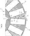
- FIG. 8depicts an embodiment of the stator 41 comprising at least two electrical phases (e.g., three phases shown).
- Each PCB layer 47can include a plurality of coils (such as traces 49) as shown for each electrical phase.
- FIG. 8illustrates coils corresponding to three phases A, B and C.
- the coils for each electrical phase A, B, Ccan be angularly offset from each other with respect to the axis 5 ( FIGS. 2 and 3 ) within each PCB layer 47 to define a desired phase angle shift between the electrical phases A, B, C.
- each trace 49 in phase Ais 120 electrical degrees apart from other traces 49 for phase A, and 40 electrical degrees apart from adjacent traces 49 for phases B and C.
- the traces 49 for phase B (relative to phases A and C) and for phase C (relative top phases A and B)are spaced likewise.
- each coile.g., trace 49
- the coilscan be configured to enable the stator 41 with two or more electrical phases (e.g., three phases shown in FIG. 8 ).
- FIG. 9is a simplified view of only some interior components of an embodiment of device 31.
- Each of the magnets 37can include a magnet radial edge or element 67 (also referred to herein as a "magnet radial edge 67"), and each of the traces 49 can include a trace radial edge or element 69 (also referred to herein as a "coil radial edge 69").
- the magnets 37are part of the rotor 33 ( FIG. 2 ) and rotate about the axis 35 with respect to the stationary stator 41.
- At least portions of the radial elements 67, 69can be skewed (i.e., not parallel) relative to each other.
- the magnet radial edges and coil radial edgesare not parallel and are angularly skewed relative to each other.
- the magnets 37illustrates a rotation position of the magnets 37 for which a radial edge portion of the magnet 37 (i.e., the magnet radial edge 69 nearing the corner of the magnet 37) is rotationally aligned with a radial edge portion of the coil 49, and which illustrates the skew between the magnet radial edge 69 and the coil radial edge 67.
- the radial elements 67, 69can be leading radial edges or trailing radial edges of the magnets 37 and traces 49.
- the magnet and trace radial edges or elements 67, 69can be linear as shown, and no portions of the magnet and trace radial elements 67, 69 are parallel when the magnets 37 and traces 49 rotationally align in the axial direction.
- the magnet radial elements 67can be angularly skewed relative to the trace radial elements 69, and the angular skew can be greater than 0 degrees, such as greater than 0.1 degrees, at least about 1 degree, at least about 2 degrees, at least about 3 degrees, at least about 4 degrees, or even at least about 5 degrees.
- the angular skewcan be not greater than about 90 degrees, such as not greater than about 60 degrees, not greater than about 45 degrees, not greater than about 30 degrees, not greater than about 25 degrees, not greater than about 15 degrees, not greater than about 10 degrees, or even not greater than about 5 degrees.
- the angular skewcan be in a range between any of these values.
- At least portions of the radial elements 67, 69can be parallel to each other during rotational alignment.
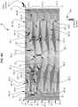
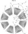
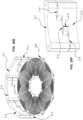
- FIGS. 10-12depict a simplified version of a device 131 with only some elements shown for ease of understanding.
- Device 131includes a stator 141 that is coaxial with a rotor 133.
- each rotor 133can include one or more slits or slots 136 ( FIG. 10 ) that extend therethrough.
- the slots 136are angled with respect to axis 135 ( FIG. 12 ) and, thus, are not merely vertical. The angles of the slots 136 can be provided at constant slopes, and can facilitate a cooling air flow within the device 131.
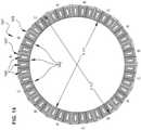
- Slots 136can enable air flow to be pulled or pushed through and/or around the rotors 133 and effectively cool the stators 141. Additional slots can be provided in rotor spacers, such as rotor spacer 143 ( FIG. 12 ), particularly in embodiments having a plurality of stator segments, and particularly in embodiments having an inner diameter R-INT of the stator assembly ( FIG. 14 ) irrespective of the outer diameter R-EXT.
- the stator 141can include a plurality of stator segments 142, each of which can be a separate PCB 145.
- the stator segments 142can be coupled together, such as mechanically and electrically coupled together.
- Each stator segment 142can include a printed circuit board (PCB) having one or more PCB layers 147 ( FIG. 13 ) as described elsewhere herein.
- PCBprinted circuit board
- each PCB 145can have an even number of PCB layers 147.
- the PCB 145can have an odd number of PCB layers 147.
- Embodiments of the stator segments 142can comprise or correspond to only one electrical phase. Moreover, the stator 141 of device 131 can consist of or correspond to only one electrical phase. In other versions, the stator 141 can comprise or correspond to a plurality of electrical phases. As shown in FIG. 13 , each stator segment 142 includes at least one PCB layer 147 having at least one conductive trace 149, such as the coil illustrated. In some versions ( FIG. 14 ), each stator segment 142 can have at least one PCB layer 147 having a plurality of traces 149 (e.g., coils) that are co-planar and angularly spaced apart from each other relative to the axis 135 ( FIGS. 11 and 12 ).
- traces 149e.g., coils
- each trace 149can comprise a single electrical phase.
- each stator segment 142can include a plurality of PCB layers 147, each of which can be configured to correspond to only one electrical phase.
- each PCB layer 147 on each stator segment 142can include a plurality of axially co-planar traces 149 that are configured to correspond to only one electrical phase.
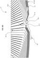
- each PCB layer 147can include at least one radial trace 150 that extends from about an inner diameter (ID) of the PCB 145 to about an outer diameter (OD) of the PCB 145.
- each PCB layer 147includes a trace 149 that is continuous from an outermost trace portion 152 to a concentric innermost trace portion 154.
- the traces 149can include radial traces 150 having linear sides and chamfered comers 156. The linear sides of the radial traces can be tapered, having an increasing trace width with increasing radial distance.
- Inner end turn traces 146 and outer end turn traces 148extend between the radial traces 150 to form a concentric coil.
- the taperscan improve the amount of conductive material (e.g., copper) that can be included in a PCB stator.
- conductive materiale.g., copper
- the coilscan be generally circular and, to fit together collectively on a stator, the perimeters of the coils can be somewhat pie-slice-shaped or triangular.
- the coilscan have a same width in a plane perpendicular to the axis, and in other versions the coils can be tapered to increase the conductor (e.g., copper) densities of the coils. Improving copper density can have significant value to reduce electrical resistance, I2R losses and heat generation, and increase the ability to carry a higher electrical current to provide a machine with higher efficiency.
- each PCB layer 147can include only linear traces 149 ( FIGS. 15-17 ).
- Linear traces 149can be continuous from an outermost trace 152 to a concentric innermost trace 154.
- no trace 149 of the PCB layers 147is non-linear.
- embodiments of the only linear traces 149can include turns, such as, for example, rounded comers or chamfered comers.
- a "turn"includes a trace portion connecting a radial trace to an end turn trace.
- the PCB layer 147can include one or more non-linear, such as curvilinear traces.
- the PCB 145includes a plurality of PCB layers 147 that are spaced apart from each other in the axial direction.
- the PCB layers 147can comprise layer pairs 157 ( FIG. 17 ; see pairs 157.1 to 157.4).
- Each layer pair 157can be defined as two PCB layers that are electrically coupled together.
- at least one of the PCB layers 147is electrically coupled to another PCB layer 147 in series or in parallel.
- at least one layer pair 157is electrically coupled to another layer pair 157 in series or in parallel.
- at least one of the layer pairs 157comprises two PCB layers 147.6 and 147.7 that are axially adjacent to each other.
- At least one of the layer pairs 157comprises two PCB layers 147.1 and 147.3 that are not axially adjacent to each other. Similarly, at least one of the layer pairs 157 can be axially adjacent to the layer pair 157 to which said at least one of the layer pairs is electrically coupled. Conversely, at least one of the layer pairs 157 can be not axially adjacent to the layer pair 157 to which said at least one of the layer pairs 157 is electrically coupled.
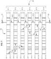
- Embodiments of the PCB layers 147can include at least one layer set 181 ( FIG. 17 ).
- layer set 181can include a first layer 147.1, a second layer 147.2, a third layer 147.3 and a fourth layer 147.4.
- a first via 159can couple the first layer 147.1 to the third layer 147.3
- a second via 155can couple the third layer 147.3 to the second layer 147.2
- a third via 159can couple the second layer 147.2 to the fourth layer 147.4.
- the first, second and third vias 159, 155, 159are the only vias that intra-couple the layer set 181.
- each of the vias 159couples a pair of non-adjacent PCB layers 147 while bypassing (i.e., making no contact to) the intervening PCB layer 147.
- via 159.1couples PCB layer 147.1 to PCB layer 147.3, and makes no contact with PCB layer 147.2.
- each of the vias 155couples a pair of adjacent PCB layers 147.
- via 155.2couples PCB layer 147.2 to PCB layer 147.3.
- Each via 155, 159 that couples together a respective pair of PCB layersforms a corresponding layer pair 157.
- layer pair 157.1includes PCB layer 147.1 and PCB layer 147.3.
- Layer pair 157.2includes PCB layer 147.2 and PCB layer 147.3.
- Layer pair 157.3includes PCB layer 147.2 and PCB layer 147.4.
- Layer pair 157.4includes PCB layer 147.4 and PCB layer 147.5.
- Layer pair 157.5includes PCB layer 147.5 and PCB layer 147.7.
- Layer pair 157.6includes PCB layer 147.6 and PCB layer 147.7.
- Layer pair 157.7includes PCB layer 147.6 and PCB layer 147.8.
- each viais shown having a blunt end and a pointed end. This shape is not intended to imply any structural difference between the two ends of each via, but rather is intended to provide a consistent indication of the direction of current flow through each via.
- each viais also shown as extending vertically only as far as necessary to couple the corresponding pair of PCB layers 147, in certain embodiments each via can be implemented as a plated through-hole via extending through the entire PCB (e.g., see vias 59 in FIG. 6D ). Each of such plated through-hole vias can make contact with any PCB layer 147 having a trace 149 that overlaps such a via. In the embodiment shown in FIG.
- a given through-hole viaoverlaps and makes a connection with only two PCB layers 147, while the traces 149 of all remaining PCB layers 147 do not overlap the given via and are not connected to the given via.
- some embodimentscan include buried vias that vertically extend only between the corresponding PCB layers 147 to be connected.
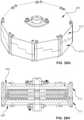
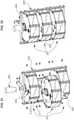
- FIGS. 18, 19 , 20A-20Hdisclose embodiments of a module 201 for one or more axial field rotary energy devices 231.
- Device(s) 231can comprise any of the axial field rotary energy device embodiments disclosed herein.
- the module 201includes a housing 203 having a side wall 211, three stators (shown as PCB stator panel 245), and four rotor assemblies 242, 244. Each rotor assembly 244 is vertically disposed between two stators 245, and includes a pair of identical rotor panels 236 and a group of rotor permanent magnets 237.
- Each rotor panel 236includes a set of recessed indentations to position each of the rotor magnets 237, and the two rotor panels 236 are secured together to sandwich each of the group of rotor magnets between the opposing upper and lower rotor panels 236.
- Each rotor assembly 242is vertically disposed between a stator 245 and a housing 203, and includes a torque plate 233, a rotor panel 234, and a group of rotor permanent magnets 237.
- the vertical spacing between rotor assembliesis maintained by spacers (e.g., 262, 263) that extend from one rotor assembly to the adjacent rotor assembly through a hole in the intervening stator panel 245.
- the rotor spacingcorresponds to the thickness of the stator panel 245 and the desired air gap spacing (such as above and/or below) the stator panel 245.
- Each rotor spacercan define the air gap between the rotor assembly and the stator (and also can define the height 215 of the side wall slots, as noted below).
- Each rotor spaceris positioned between two rotor assemblies.
- rotor spacer 262is positioned between the uppermost rotor assembly 242 and the adjacent inner rotor assembly 244 (and likewise for the lowermost rotor assembly 242).
- Each rotor spacer 263is positioned between adjacent inner rotor assemblies 244.
- such rotor spacer 263can have a different thickness as rotor spacer 262, due to mechanical differences in the uppermost and lowermost rotor assemblies 242 relative to the inner rotor assemblies 244, to define the same air gap spacing between all rotors and stators.
- the use of the rotor spacers 262, 263enables stacking multiple rotors (e.g., rotor assemblies 242, 244), which can provide significant flexibility in the configuration of module 201.
- Embodiments of the housing 203can include a side wall 211 ( FIGS. 20A-20H and 21 ).
- Side wall 211can be configured to orient the stator (e.g., stator panel 245) at a desired angular orientation with respect to the axis 235.
- the side wall 211can comprise a plurality of side wall segments 212.
- the side wall segments 212can be configured to angularly offset the plurality of stators 245 at desired electric phase angles (see, e.g., FIGS. 20C and 25 ) for the module 201, relative to the axis.
- the side wall 211can include a radial inner surface having one or more slots 214 formed therein.
- each slot 214can be configured to receive and hold the outer edge of the stator 245 to maintain the desired angular orientation of the stator 245 with respect to the axis 235.
- each side wall 211includes three slots 214 formed between mating pairs of side wall segments 212.
- the upper and lower sidewall segments 212 of such mating pairare identical and thus can be used interchangeably, but in other contemplated embodiments the upper and lower side wall segments 212 can be different due to asymmetrical slots 214, differences in mounting hole placement, or some other aspect.
- the slots 214can be configured to axially, such as vertically, position the outer edge of each stator 245 at prescribed axial positions with respect to other stators 41. Since the rotor spacers 262, 263 determine the axial spacing between each stator 245 (at the innermost extent thereof) and the corresponding rotor assembly (e.g., 242, 244 in FIGS.
- each stator 245on either axial side (e.g., above and below) each stator 245, the combination of the side wall slots 214 (i.e., the height 215 of such slots 214) and the rotor spacers 262, 263 serve to maintain a precise air gap spacing between stators 245 and rotor assemblies 242, 244.
- each side wall segment 212can be configured to provide one side wall slot 214.
- the group of side wall segments 212together provide numerous slots 214 (e.g., eight such slots 214) radially spaced around the module 201.
- Collectively such side wall slots 214can be viewed as facilitating the air gap spacing between the stator and the adjacent rotor.
- Versions of the module 201can include a housing 203 having mechanical features (e.g., keyed shafts 209 in FIG. 21 ) configured to mechanically couple the housing 203 to a second housing 203 of a second module 201.
- housing 203can be configured with electrical elements (e.g., electrical connector couplings 204 in FIGS. 21 and 22 ) to electrically couple the housing 203 to the second housing 203.
- the module 201is air cooled and is not liquid cooled. In other versions, liquid- cooled embodiments can be employed.
- the module 201can be configured to be indirectly coupled to the second module 201 with an intervening structure, such as a frame 205 ( FIGS. 21-22 ).
- the module 201can be configured to be directly coupled to the frame 205, such that the module 201 is configured to be indirectly coupled to the second module 201 with other components depending on the application.
- the module 201can be configured to be directly coupled to the second module 201 without a frame, chassis or other intervening structure.
- At least one rotor 233, at least one magnet 237 and at least one stator 241 having at least one PCB 245 with at least one PCB layer 147 having at least one trace 149can be located inside and surrounded by the housing 203.
- each module 201consists of a single electrical phase. In other versions each module 201 comprises a plurality of electrical phases. Examples of each module 201 can include a plurality of PCB panels 245 ( FIGS. 20A-20H ). Each PCB panel 245 can comprise a single electrical phase or a plurality of electrical phases. The PCB panels can be unitary panels or can comprise stator segments as described elsewhere herein.
- the module 201 and the second module 201can be configured to be identical to each other. In another version, the module 201 and the second module 201 can differ.
- the module 201can differ from the second module 201 by at least one of the following variables: power input or output, number of rotors 233, number of magnets 237, number of stators 41 (see previous drawings), number of PCBs 245, number of PCB layers 47 (see previous drawings), number of traces 49 (see previous drawings), and angular orientation with respect to the axis 235.
- one or more of these variablescan be modified to achieve differences in power efficiency, torque, achievable revolutions per minute (RPM), so that different modules 201 can be utilized to better tailor operation as a function of the load or other desired operating parameter.
- RPMrevolutions per minute
- the module 201can include at least one latch 207 ( FIGS. 23 and 24 ) configured to mechanically secure the modules together.
- FIG. 23depicts modules nested together with the latches 207 open
- FIG. 24depicts modules nested together with the latches 207 closed.
- the latches 207can be symmetrically arrayed with respect to the axis 235.
- a top module(not shown) can be configured to be axially on top of another module, and the top module can differ structurally from the second module.
- the top module 201can include latches 207 only on its bottom side, and omit such latches 207 on its top side.
- the shaft 209can extend from the bottom module 201, but not from the top module 201.
- the module 201can include a keyed shaft 209. Module 201 can be mounted to the keyed shaft which can be configured to mechanically couple to another module 201.
- Some embodimentscan further comprise a body 213 ( FIG. 26 ) (also referred to herein as an "enclosure").
- Body 213can be configured to contain and coaxially mount a plurality of the modules 201 within the body 213.
- the body 213comprises two halves that are coupled together with fasteners.
- each module 201comprises a single electrical phase
- the body 213can be configured to maintain the modules 201 at a desired electrical phase angle with respect to the axis 235.
- the body 213comprises a plurality of electrical phases
- the body 213can be configured to maintain the modules 201 at desired electrical phase angles with respect to the axis 235.
- each body 213can include mechanical features such as coupling structures configured to mechanically couple each body 213 to at least one other body 213, and electrical elements configured to electrically couple each body 213 to at least one other body 213.
- Each body 213can be configured to directly or indirectly couple to at least one other body 213.
- a body(or more than one intercoupled bodies) can include a number of electrical phases (such as about 4 to 99; e.g., at least 10, 11, 12, 13, 14, 15 or more) electrical phases of alternating current output.
- the AC current outputcan act like a DC-like output ripple without being rectified or requiring a power conversion. In other versions, such AC current output can be rectified.
- Embodiments of a system for providing energyalso are disclosed.
- the systemcan include a plurality of modules 201 comprising axial field rotary energy devices.
- the modules 201can be interchangeably connectable to each other to configure the system for a desired power output.
- Each modulecan be configured based on any of the embodiments described herein.
- the systemcan comprise a generator or a motor.
- Embodiments of the systemcan include at least two of the modules 201 configured to differ.
- the modules 201can differ from each other by at least one of the following variables: power output or input, number of rotors, number of magnets, number of stators, number of PCBs, number of PCB layers, number of coils, and angular orientation with respect to the axis.
- Embodiments of a method of repairing an axial field rotary energy deviceare disclosed as well.
- the methodcan include the following steps: providing a body 213 having a plurality of modules 201.
- Each module 201can be configured as described for any of the embodiments disclosed herein.
- the methodalso can include mechanically and electrically coupling the modules 201 such that the modules 201 are coaxial; operating the axial field energy device; detecting a problem with one of the modules 201 and stopping operation of the axial field energy device; opening the body 213 and de- attaching the problem module 201 from all other modules 201 to which the problem module 201 is attached; installing a replacement module 201 in the body 213 in place of the problem module 201 and attaching the replacement module 201 to the other modules 201 to which the problem module 201 was attached; and then re-operating the axial field energy device.
- the methodinclude angularly aligning the modules to at least one desired electrical phase angle with respect to the axis.
- the methodcan include providing a plurality of bodies 213, and mechanically and electrically coupling the bodies 213.
- Still other embodiments of a method of operating an axial field rotary energy devicecan include providing an enclosure having a plurality of modules, each module comprises a housing, rotors rotatably mounted to the housing, each rotor comprises an axis and a magnet, stators mounted to the housing coaxially with the rotors, each stator comprises a printed circuit board (PCB) having a coil, each stator consists of a single electrical phase, and selected ones of the stators are set at desired phase angles with respect to the axis; mechanically and electrically coupling the modules such that the modules are coaxial within the enclosure; and then operating the axial field energy device.
- PCBprinted circuit board
- the enclosure and each modulecan comprise a single electrical phase
- the methodcan comprise angularly aligning the modules at a desired electrical phase angle with respect to the axis.
- the methodcan include the enclosure with a plurality of electrical phases, each module comprises a single electrical phase, and angularly orienting the modules at desired electrical phase angles with respect to the axis.
- the enclosure and each modulecan include a plurality of electrical phases, and angularly misaligning the modules at desired electrical phase angles with respect to the axis.
- Some versions of the methodcan include providing a plurality of bodies, and the method further comprises mechanically and electrically coupling the bodies to form an integrated system.
- Each modulecan include a plurality of stators that are angularly offset from each other with respect to the axis at desired electrical phase angles.
- each statorconsists of only one PCB.
- each statorcomprises two or more PCBs that are coupled together to form each stator.
- the enclosurecan have a number electrical phases of alternating current (AC) output that is substantially equivalent to a clean direct current (DC)-like ripple without a power conversion, as described herein.
- ACalternating current
- DCdirect current
- a method of repairing an axial field rotary energy devicecan include providing a plurality of bodies that are coupled together, each enclosure having a plurality of modules, each module comprising a housing, a rotor rotatably mounted to the housing, the rotor comprises an axis and a magnet, a stator mounted to the housing coaxially with the rotor, and the stator comprises a printed circuit board (PCB); mechanically and electrically coupling the modules; operating the axial field rotary energy device; detecting an issue with a first module in a first enclosure and stopping operation of the axial field rotary energy device; opening the first enclosure and disassembling the first module from the first enclosure and any other module to which the first module is attached; installing a second module in the first enclosure in place of the first module and attaching the second module to said any other module to which the first module was attached; and then re-operating the axial field rotary energy device.
- PCBprinted circuit board
- Embodiments of each modulecan have only one orientation within the enclosure, such that each module can be installed or uninstalled relative to the enclosure in singular manners.
- the purpose of such designsis so the person doing work on the system cannot re-install new modules into an existing system the wrong position. It can only be done in only one orientation.
- the methodcan occur while operation of the AFRED is suspended, and treatment of the first module occurs without interrupting said any other module, and without modifying or impacting said any other module.
- FIG. 27depicts another embodiment of a PCB stator 311 for an axial field rotary energy device, such as those disclosed herein.
- PCB stator 311comprises a substrate having one or more traces 313 that are electrically conductive.
- PCB stator 311comprises eight coils of traces 313.
- PCB stator 311comprises more than one layer of traces 313.
- the traces 313 on each layerare co-planar with the layer.
- the traces 313are arrayed about a central axis 315 of the PCB stator.
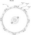
- FIG. 28is an enlarged top view of a portion of the PCB stator of FIG. 27 .
- each trace 313comprises radial portions 317 (relative to axis 315) and end turns 319 extending between the radial portions 317.
- Each trace 313can be split with a slit 321.
- only radial portions 317comprise slits 321.
- Slits 321can help reduce eddy current losses during operation. Eddy currents oppose the magnetic field during operation. Reducing eddy currents increases magnetic strength and increases efficiency of the system.
- wide tracescan allow eddy currents to build.
- the slits in the traces 313can reduce the opportunity for eddy currents to form.
- the slitscan force the current to flow through the traces 313 more effectively.
- the axial field rotary energy devicecan comprise a "smart machine” that includes one or more sensors integrated therewith.
- a sensorcan be configured to monitor, detect, or generate data regarding operation of the axial field rotary energy device.
- the operational datacan include at least one of power, temperature, rate of rotation, rotor position, or vibration data.
- Versions of the axial field rotary energy devicecan comprise an integrated machine that includes one or more control circuits integrated therewith.
- Other versions of the axial field rotary energy devicecan comprise a fully integrated machine that includes one or more sensors and one or more control circuits integrated therewith.
- one or more sensors and/or control circuitscan be integrated with the PCB and/or integrated with the housing.
- these control circuitscan be used to drive or propel the machine.
- such a control circuitcan include an input coupled to receive an external power source, and can also include an output coupled to provide a current flowing through one or more stator coils.
- the control circuitis configured to supply torque and/or torque commands to the machine.
- such a control circuitcan include an input coupled to receive the current flowing through the coil, and can also include an output coupled to generate an external power source.
- FIG. 29shows another exemplary stator 340 having integrated sensors (e.g., 342, 346) that are attached to its uppermost PCB layer 47.
- One such sensor 342is coupled to a secondary coil 344 that can be used to transmit/receive data to/from an external device, and can be also used to couple power to the sensor 342.
- the secondary coilcan be configured to utilize magnetic flux developed during operation to provide power for the sensor 342.
- the secondary coilcan be configured to receive inductively coupled power from an external coil (not shown).
- the secondary coil 344may also be referred to herein as a micro-coil, or a miniature coil, as in certain embodiments such a secondary coil can be much smaller than a stator coil 49, but no relative size inference is intended. Rather, such a secondary coil 344 is distinct from the stator coils 49 that cooperate with the rotor magnets, as described above.
- a secondary coil integrated with the PCB stator 311can, in certain embodiments, be disposed on the PCB stator 311 (e.g., fabricated on, or attached to, its uppermost PCB layer 47).
- Such a secondary coil integrated with the PCB stator 311can, in certain embodiments, be disposed within (i.e., embedded within) the PCB stator 311.
- the secondary coil 344provides power to a sensor connected thereto. Such coupled power can be primary or auxiliary power for the sensor.
- Sensor 346is coupled to the first terminal 51 for one of the traces 49 on the upper PCB layer 47, and can sense an operating parameter such as voltage, temperature at that location, and can also be powered by the attached coil (e.g., one of the coils 49).
- Sensor 348is coupled to an external terminal 350, and likewise can sense an operating parameter such as voltage, temperature at that location, and can also be powered by the voltage coupled to the external terminal 350.
- Sensor 350is disposed at an outer edge of the PCB stator 340, but is coupled to no conductor on the PCB layer 47.
- such a sensorcan be embedded directly in one of the coils 49 and can be electrically powered directly by the coil 49.
- such a sensorcan be powered and connected to the coil 49 through a separate connection that is disposed on or within the PCB layer 47, such as the connection between the first terminal 51 and sensor 346.
- a connectioncan be disposed on the PCB layer 47 or disposed within the PCB (e.g., on an internal layer of the PCB).
- the sensor and/or circuitrycan get power from an external power source.
- one type of external power sourcecan be a conventional wall electrical socket which can be coupled to the housing of the motor or generator.
- the sensorscan provide operators of generator or motor products with real time operational data as well as, in certain embodiments, predictive data on various parameters of the product. This can include how the equipment is operating, and how and when to schedule maintenance. Such information can reduce product downtime and increase product life.
- the sensorcan be integrated within the housing.
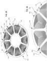
- the sensorscan be embedded within the PCB stator 340, as is shown in FIG. 30 (e.g., sensors 362, 366, 368, 372, and coil 364).
- Hall effect sensorsare used for proximity switching, positioning, speed detection, and current sensing applications.
- the Hall effect sensoroperates as an analog transducer, directly returning a voltage.
- a sensoris an optical sensor.
- Optical sensorscan measure the intensity of electromagnetic waves in a wavelength range between UV light and near infrared light.
- the basic measurement deviceis a photodiode. Combining a photodiode with electronics makes a pixel.
- the optical sensorcan include an optical encoder that uses optics to measure or detect the positions of the magnetic rotor.
- thermocouple sensorto measure temperature.
- Thermocouplescomprise two wire legs made from different metals. The wires legs are welded together at one end, creating a junction. The junction is where the temperature is measured. When the junction experiences a change in temperature, a voltage is created.
- Accelerometersare an electromechanical device used to measure acceleration forces. Such forces can be static, like the continuous force of gravity or, as is the case with many mobile devices, dynamic to sense movement or vibrations. Acceleration is the measurement of the change in velocity, or speed divided by time.
- a gyro sensorwhich functions like a gyroscope, also can be employed in these systems.
- Gyro sensorscan be used to provide stability or maintain a reference direction in navigation systems, automatic pilots, and stabilizers.
- the PCB stator 340also can include a torque sensor.
- a torque sensor, torque transducer or torque meteris a device for measuring and recording the torque on a rotating system, such as the axial field rotary energy device.
- Vibration sensorscan measure, display and analyze linear velocity, displacement and proximity, or acceleration. Vibration, even minor vibration, can be a telltale sign of the condition of a machine.
- the sensors depicted in FIG. 29 and FIG. 30can also represent control circuits integrated with the PCB stator 345.
- control circuitscan be disposed on a surface of the PCB (analogously to the sensors depicted in FIG. 29 ), disposed within (i.e., embedded within) the PCB (analogously to the sensors depicted in FIG. 30 ), and/or integrated with or within the housing (e.g., housing 203 in FIG. 18 ).
- the control circuitcan implement power conversion from an AC voltage developed in the stator coils to an external desired power source (e.g., an AC voltage having a different magnitude than the coils voltage, a DC voltage developed by rectifying the coils voltage).
- the control circuitcan implement an integrated drive circuitry that can provide desired AC current waveforms to the stator coils to drive the motor.
- the integrated drivecan be a variable frequency drive (VFD), and can be integrated with the same housing as the motor.
- VFDvariable frequency drive
- the sensors and/or circuitry disclosed hereincan be wirelessly or hard-wired to any element of, on or in the housing. Alternatively, the sensors and/or circuitry can be located remotely relative to the housing.
- Each of these sensors and control circuitscan include a wireless communication circuit configured to communicate with an external device through a wireless network environment.
- Such wireless communicationcan be unidirectional or bidirectional, and can be useful for monitoring a status of the system, operating the system, communicating predictive data, etc.
- the wireless communication via the networkcan be conducted using, for example, at least one of long term evolution (LTE), LTE-advanced (LTE-A), code division multiple access (CDMA), wideband CDMA (WCDMA), universal mobile telecommunication system (UMTS), wireless broadband (WiBro), or global system for mobile communications (GSM), as a cellular communication protocol.
- LTElong term evolution
- LTE-ALTE-advanced
- CDMAcode division multiple access
- WCDMAwideband CDMA
- UMTSuniversal mobile telecommunication system
- WiBrowireless broadband
- GSMglobal system for mobile communications
- the wireless communicationcan include, for example, short-range communication.
- the short-range communicationcan be conducted by, for example, at least one of wireless fidelity (WiFi), Bluetooth ® , near field communication (NFC), or GNSS.
- GNSScan include, for example, at least one of global positioning system (GPS), Glonass ® global navigation satellite system, Beidou ® navigation satellite system, or Galileo ® , the European global satellite-based navigation system.
- GPSglobal positioning system
- Glonass ® global navigation satellite systemBeidou ® navigation satellite system
- Galileo ®the European global satellite-based navigation system.
- the networkcan be a communication network, for example, at least one of a computer network (for example, local area network (LAN) or wide area network (WAN)), the Internet, or a telephone network.
- such a wireless communication circuitcan be coupled to a secondary coil (e.g., secondary coil 344) to communicate telemetry information, such as the operational data described above.
- a secondary coile.g., secondary coil 3414
- FIGS. 31 and 32show an embodiment of an assembly for mechanically coupling together stator segments 380 to form a stator.
- a clasp 382slides over portions of a mounting pad 381 on two adjacent stator segments 380, which is secured by a pair of nuts on each of two bolts (e.g., bolt 384).
- the clasp 382includes an alignment tab 392 that can be positioned into a side wall slot 214 as described above.
- the inner diameter edge of the two adjacent stator segments 380slides into a channeled rotor spacer 390 in the shape of an annular ring.
- this rotor spacer 390can ride on a thrust bearing with the rotor to allow the rotor spacer 390 and stator to remain stationary while the rotor rotates.
- a rotor spacer as described abovee.g., FIGS. 18 , 20A-20H
- Circuit 386can connect to a trace on the upper layer (or another layer using a via) of the stator segment 380.
- circuit 388can connect to a trace on any layer of the stator segment 381.
- Such circuits 386, 388can include any of the sensors described above ( FIGS. 29-30 ), but can also merely provide an electrical connection from the respective PCB to the wire 387.
- electrical connectionalso can be made via the mounting surface of the PCB being a conductive material and connected to the coil and then coupling those components through the clasp, which also can include conductive material on the inner surface thereof.
- Electrical connectioncan also be implemented using the clasp 382 m combination with an electrically conductive mounting pad 383. If the mounting pad 383 is continuous and unbroken, the clasps 382 can provide a common electrical connection around the circumference of the stator. If such mounting pads are discontinuous and broken into two pieces (as shown by the dash lines, with each piece coupled to a respective terminal of a trace on that segment, the clasps 382 can serially connect such stator segments.
- the axial field rotary energy deviceis suitable for many applications.
- the PCB stator 340can be configured for a desired power criteria and form factor for devices such as permanent magnet-type generators and motors. Such designs are lighter in weight, easier to produce, easier to maintain and more capable of higher efficiency.
- Examples of permanent magnet generator (PMG) applicationscan include a wind turbine generator, micro-generator application, permanent magnet direct drive generator, steam turbine generator, hydro generator, thermal generator, gas generator, wood-fire generator, coal generator, high frequency generator (e.g., frequency over 60 Hz), portable generator, auxiliary power unit, automobiles, alternator, regenerative braking device, PCB stator for regenerative braking device, back-up or standby power generation, PMG for back up or standby power generation, PMG for military usage and a PMG for aerospace usage.
- PMGpermanent magnet generator
- examples of a permanent magnet motorcan include an AC motor, DC motor, servo motor, stepper motor, drone motor, household appliance, fan motor, microwave oven, vacuum machine, automobile, drivetrain for electric vehicle, industrial machinery, production line motor, internet of things sensors (IOT) enabled, heating, ventilation and air conditioning (HVAC), HVAC fan motor, lab equipment, precision motors, military, motors for autonomous vehicles, aerospace and aircraft motors.
- IOTinternet of things sensors
- HVACheating, ventilation and air conditioning
- HVACheating, ventilation and air conditioning
- the term “or”is inclusive, meaning and/or.
- phrases "at least one of,” when used with a list of items,means that different combinations of one or more of the listed items can be used, and only one item in the list can be needed.
- “at least one of: A, B, and C”includes any of the following combinations: A, B, C, A and B, A and C, B and C, and A and Band C.
- PCBprinted circuit board
- PWBprinted wiring board
- a coil on a PCBis an electrically conductive coil.
- a component or object "integrated with" a structurecan be disposed on or within the structure. Such a component or object can be mounted, attached to, or added to the structure after the structure itself is manufactured, or the component or object can be embedded within or fabricated with the structure.
- Some embodiments described hereinutilize one via to couple together two coils. In other embodiments a plurality of vias can be provided instead of a single via to couple together such coils.
Landscapes
- Engineering & Computer Science (AREA)
- Power Engineering (AREA)
- Manufacturing & Machinery (AREA)
- Windings For Motors And Generators (AREA)
- Permanent Magnet Type Synchronous Machine (AREA)
- Superconductive Dynamoelectric Machines (AREA)
Description
- The present invention relates to a module for an axial field rotary energy device including a housing, a plurality of rotors rotatably mounted to the housing, and a stator mounted to the housing coaxially with the rotors.
- Conventional, axial air gap brushless motors with layered disk stators are known, such as
US 5789841 . That patent discloses a stator winding that uses wires interconnected in a wave or lap configuration. Such motors are relatively large and difficult to manufacture. Axial field electric devices that use PCB stators also are known, such asUS 6411002 ,US 7109625 andUS 8823241 . However, some of these designs are complicated, relatively expensive and they are not modular. Thus, improvements in cost-effective axial field rotary energy devices continue to be of interest. US 2009/051317 A1 discloses a human-powered slim charger utilizing an axial flux alternator for converting a pull-out motion into an electrical current for charging and supplying battery-fed electronic devices. The charger comprises mechanical transmission means for converting a periodic linear movement into a unidirectional rotation, an axial flux alternator comprising a stator comprising a planar winding, having a plurality of coils embedded in multiple layers within said stator and circularly distributed around a central axis and two essentially identical rotors arranged to rotate together around said central axis and allocated concentrically with said winding on both sides of said stator facing each other; wherein each said rotor comprises a periodical heteropolar axially magnetized magnetic system having a definite number of poles. Finally, the device comprises a charging control module affixed to the stator, said control module configured effectively convert non-stable alternating current produced by said alternator into a charging direct current.- Embodiments of a module for an axial field rotary energy device are disclosed. An axial field rotary energy device includes a housing having coupling structures configured to mechanically couple the housing to a second housing of a second module, and electrical elements configured to electrically couple the housing to the second housing; a plurality of rotors rotatably mounted to the housing, and the rotors comprise an axis and a plurality of magnets; and a stator mounted to the housing coaxially with the rotor, and the stator comprises a printed circuit board (PCB) having a plurality of PCB layers comprising. Each PCB layer comprises a respective plurality of coils that are co-planar and angularly and symmetrically spaced apart from each other relative to the axis. Each coil is continuous and concentric in a single plane from an outermost coil portion to a concentric innermost coil portion, the coils in adjacent PCB layers are circumferentially aligned with each other relative to the axis to define symmetric stacks of coils in an axial direction. Each coil includes a first terminal at the outer edge of the coil, and a second terminal in the center of the coil. Each coil is not directly connected to an adjacent coil on the same PCB layer. Each coil is directly connected to a corresponding coil on another PCB layer through a via to create a coil pair. Each coil pair is electrically coupled to another coil pair through another via.
- In one embodiment, the housing comprises a side wall that orients the stator at respective angular orientations with respect to the axis.
- The foregoing and other objects and advantages of these embodiments will be apparent to those of ordinary skill in the art in view of the following detailed description, taken in conjunction with the appended claims and the accompanying drawings.
- So that the manner in which the features and advantages of the embodiments are attained and can be understood in more detail, a more particular description can be had by reference to the embodiments thereof that are illustrated in the appended drawings. However, the drawings illustrate only some embodiments and therefore are not to be considered limiting in scope as there can be other equally effective embodiments.
FIG. 1 is a top view of an embodiment of an axial field rotary energy device.FIG. 2 is a sectional side view of the device ofFIG. 1 , taken along the line 2-2 ofFIG. 1 .FIG. 3 is an exploded isometric view of an embodiment of the device ofFIGS. 1 and 2 .FIG. 4 is a top view of an embodiment of a single phase stator having a printed circuit board (PCB).FIG. 5 is an enlarged isometric view of an embodiment of only the coil layers of a stator.FIG. 6A is an enlarged, exploded, isometric view of another embodiment of only the coil layers of a stator.FIG. 6B is an enlarged isometric view of a portion of the stator shown inFIG. 5 .FIG. 6C is an enlarged, exploded, isometric view of a portion of the stator shown inFIG. 5 .FIG. 6D is an enlarged isometric view of a portion of the stator shown inFIG. 5 .FIG. 7 is a schematic, partially exploded side view of an embodiment of the traces on the layers of a stator.FIG. 8 is a top view of an embodiment of a multi-phase stator having a PCB.FIG. 9 is a top view of an alternate embodiment of the top coil layer of a stator and magnets of the vertically adjacent rotors.FIG. 10 is a simplified top view of an embodiment of another embodiment of an axial field rotary energy device.FIG. 11 is a simplified sectional side view of the device ofFIG. 10 .FIG. 12 is a simplified, exploded, isometric view of an embodiment of the device ofFIGS. 10 and 11 .FIG. 13 is a simplified top view of an embodiment of a segmented stator.FIG. 14 is a simplified top view of another embodiment of a segmented stator.FIG. 15 is a simplified top view of an embodiment of traces for a PCB.FIG. 16 is a simplified isometric view of the embodiment ofFIG. 15 .FIG. 17 is a schematic, exploded, isometric view of an embodiment of trace layers of the PCB ofFIGS. 15 and 16 .FIG. 18 is a top view of an embodiment of a module.FIG. 19 is a sectional side view of the module ofFIG. 18 , taken along the line 19-19 ofFIG. 18 .FIG. 20A is an exploded isometric view of an embodiment of the module ofFIGS. 18 and 19 .FIGS. 20B-20H are isometric and sectional side views of embodiments of the module ofFIG. 20A .FIG. 21 is an exploded isometric view of another embodiment of a module.FIG. 22 is an assembled isometric view ofan embodiment of the module ofFIG. 21 .FIGS. 23 and 24 are isometric views of an embodiment of stacked modules with latches open and closed, respectively.FIG. 25 is a top, interior view of an embodiment of a module.FIG. 26 is an exploded isometric view of an embodiment of a body for modules.FIG. 27 is a top view of an embodiment of a PCB stator for an axial field rotary energy device.FIG. 28 is an enlarged top view of a portion of an embodiment of the PCB stator ofFIG. 27 .FIG. 29 is an isometric view of an embodiment of a stator that includes attached sensors.FIG. 30 is an isometric view of an embodiment of a stator that includes embedded sensors.FIG. 31 is an isometric view of an embodiment of an assembly for stator segments.FIG. 32 is an opposite isometric view of an embodiment of an assembly for stator segments.- The use of the same reference symbols in different drawings indicates similar or identical items.
FIGS. 1-3 depict various views of an embodiment of adevice 31 comprising an axial field rotary energy device (AFRED). Depending on the application,device 31 can comprise a motor that converts electrical energy to mechanical power, or a generator that converts mechanical power to electrical energy.- Embodiments of
device 31 include at least onerotor 33 comprising anaxis 35 of rotation and a magnet (i.e., at least one magnet 37). A plurality ofmagnets 37 are shown in the embodiment ofFIG. 3 . Eachmagnet 37 can include at least one magnet pole. Device 31 also include astator 41 that is coaxial with therotor 33.Rotor 33 can be coupled on ashaft 43 and with other hardware, such as one or more of the following items: a mount plate, fastener, washer, bearing, spacer or alignment element. Embodiments of thestator 41 can include a single unitary panel, such as the printed circuit board (PCB) 45 shown inFIG. 4 .PCB 45 includes at least onePCB layer 47. For example, certain embodiments described herein include twelve PCB layers 47. PCB layers 47 can be parallel and spaced apart in the axial direction. EachPCB layer 47 includes at least oneconductive trace 49. Eachtrace 49 is a separate conductive feature formed on a givenPCB layer 47. For example, eighttraces 49 are shown inFIG. 4 .Traces 49 can be configured in a desired pattern, such as the coils illustrated inFIG. 4 .FIG. 4 depicts an embodiment of onePCB layer 47 within a twelve-layer PCB 45. The other eleven PCB layers are similar, with differences described below in regards to subsequent figures. On the illustratedPCB layer 47, each trace 49 (forming a single coil) includes afirst terminal 51 at the outer edge of the coil, and asecond terminal 53 in the center of coil.Traces 49 are connected toother traces 49 usingvias 55. A first set ofvias 55 is disposed adjacent to thefirst terminal 51 at the outer edge of each coil, and a second set ofvias 55 is disposed adjacent to the second terminal in the center of each coil. In this embodiment, traces 49 on the illustratedPCB layer 47 are not directly connected to anadjacent trace 49 on this illustratedPCB layer 47, but rather are each directly connected to acorresponding trace 49 on anotherPCB layer 47, as more thoroughly explained in regards toFIG. 5 andFIGS. 6A-6D .- In this embodiment, each
trace 49 is continuous and uninterrupted from itsfirst terminal 51 to itssecond terminal 53, and connections tosuch trace 49 are made only to the first andsecond terminals trace 49 includes no other terminals for electrical connections. In other words, eachtrace 49 can be seamlessly continuous with no other electrical connections, including noadditional vias 55, between the first andsecond terminals FIG. 4 , the width of a giventrace 49 can be not uniform. For example,width 171 corresponding to an outer trace corner can be wider thanwidth 173 corresponding to an inner trace corner.Gap 175 between adjacent concentric trace portions forming a single coil can be the same or different than thegap 177 between adjacent traces (i.e., separate coils). In some embodiments, a given trace can comprise an outer width that is adjacent an outer diameter of the PCB and in a plane that is perpendicular to theaxis 35, and an inner width that is adjacent an inner diameter of the PCB and in the plane. In some embodiments the outer width can be greater than the inner width. In some embodiments a given trace can comprise inner and outer opposing edges that are not parallel to each other. FIG. 5 depicts an embodiment of a twelve-layer PCB 45 incorporating thePCB layer 47 shown inFIG. 4 . Each of the twelve PCB layers 47 are closely spaced and form a "sandwich" of PCB layers 47, labeled as 47.1-12. On the uppermost PCB layer 47.1, a first trace 49.11 (also described herein as "coil 49.11") is shown whose first terminal 51.1 is coupled to anexternal terminal 61 for thedevice 31. On the lowermost PCB layer 47.12, a trace 49.128 is shown whose first terminal 51.12 is coupled to anexternal terminal 63 for thedevice 31. In this embodiment, there are eight traces 49 (coils) on each of twelve PCB layers 47.1-12. These traces are coupled together (as more fully described below) such that current flowing into theexternal terminal 61 will flow through the ninety-six coils, then flow out the external terminal 63 (or conversely flow intoexternal terminal 63 and out external terminal 61). In this embodiment, only one trace 49 (e.g., coil 49.11) is coupled to theexternal terminal 61 for thedevice 31, and only one trace 49 (e.g., coil 49.128) is coupled to theexternal terminal 63 for thedevice 31. For a motor, bothexternal terminals external terminals FIG. 6A is an exploded view of a portion of the twelve-layer PCB 45 shown inFIG. 5 , which is labeled to better illustrate how the coils are coupled together by vias 55, 59, and thus to better illustrate how current flows into theexternal terminal 61, through the ninety-six coils, then flows out theexternal terminal 63. Assume that input current 81.1 flows intoexternal terminal 61. This current flows "spirally" around coil 49.11 (on PCB layer 47.1) as current 81.2 and 81.3, and reaches thesecond terminal 53 of coil 49.11. A via 55.1 couples thesecond terminal 53 of coil 49.11 to the second terminal of the corresponding coil 49.21 on PCB layer 47.2 directly below coil 49.11. Thus, the current flows through via 55.1 as current 81.4, then flows spirally around coil 49.21 as current 81.5 until it reaches thefirst terminal 51 for coil 49.21. A via 55.2 couples thefirst terminal 51 of coil 49.21 to the first terminal of coil 49.12 on PCB layer 47.1, which is adjacent to the first coil 49.11. In this embodiment, thetraces 49 on the first PCB layer 47.1 are generally reversed (mirror-imaged) relative to those on the second PCB layer 47.2, so that the via 55.1 overlaps with both "tabs" on the respectivesecond terminal 53 of coils 49.11 and 49.21, and likewise so that the via 55.2 overlaps with both "tabs" on the respectivefirst terminal 51 of coils 49.12 and 49.21, as is more thoroughly described below in regards to subsequent figures. Thus, the current flows through via 55.2 as current 82.1 to thefirst terminal 51 of coil 49.12 on PCB layer 47.1.- From this terminal, the current flows through coils 49.12 and 49.22 similarly to that described for coils 49.11 and 49.21. For example, the current flows around coil 49.21 (on PCB layer 47.1) as current 82.2 and 82.3 to the
second terminal 53 of coil 49.21, flows through via 55.3 as current 82.4 to thesecond terminal 53 of coil 49.22, then flows as current 82.5 and 82.6 around coil 49.22 until it reaches thefirst terminal 51 for coil 49.22. As before, a via 55.4 couples thefirst terminal 51 of coil 49.22 to thefirst terminal 51 of coil 49.13 on PCB layer 47.1, which is adjacent to coil 49.12. This coupling configuration is replicated for all remainingtraces 49 on the upper two PCB layers 47.1, 47.2, and the current flows through these remainingtraces 49 until it reaches the last coil 49.28 on PCB layer 47.2. The current, after having already flowed through all sixteen coils on the upper two PCB layers 47.1, 47.2, is now directed to the next PCB layer 47.3. Specifically, a via 59.1 couples thefirst terminal 51 of coil 49.28 to the first terminal of coil 49.31 on PCB layer 47.3, which is directly below coils 49.11 and 49.21. In this embodiment there is only one such via 59 coupling a coil on PCB layer 47.2 to a coil on PCB layer 47.3. Conversely, there are fifteensuch vias 55 coupling together coils on PCB layers 47.1, 47.2. In this embodiment such coupling occurs only at the first andsecond terminals - The
vias 55 between the third and fourth PCB layers 47.3, 47.4 are configured identically as those between the first and second PCB layers 47.1, 47.2 described above, and thus the via configuration and the corresponding current flow need not be repeated. This continues downward through the PCB layer "sandwich" until reaching the lowermost PCB layer 47.12 (not shown here). As described above, thefirst terminal 51 for trace (coil) 49.128 is coupled to theexternal terminal 63. Consequently, the current that flows inward throughexternal terminal 61, after flowing through all ninety-six coils, flows outward throughexternal terminal 63. FIG. 6B is an enlarged view of a group ofvias 55 shown inFIG. 5 . This via group is adjacent to the respectivesecond terminal 53 for each of a group of vertically aligned coils 49.1-12 on each of the twelve PCB layers 47.1-12. As noted above, thetraces 49 on the second PCB layer 47.2 are generally reversed (mirror-imaged) relative to those on the first PCB layer 47.1, so that the via 55 overlaps with both "tabs" on the respectivesecond terminal 53 of these vertically adjacent coils. As shown inFIG. 6B , on coil 49.18 (first layer, eighth coil) the second terminal 53.18 includes a tab extending to the side of the trace. In mirror-image fashion, on coil 49.28 (second layer, eighth coil) the second terminal 53.28 includes a tab extending in the opposite direction to the side of the trace, so that these two tabs overlap. A via 55 couples together these two overlapping tabs. In like manner, since the embodiment shown includes 12 PCB layers 47, each of fiveadditional vias 55 respectively couples overlapping terminals 53.38 and 53.48, overlapping terminals 53.58 and 53.68, overlapping terminals 53.78 and 53.88, overlapping terminals 53.98 and 53.108, and overlapping terminals 53.118 and 53.128.FIG. 6C shows two of thesevias 55 in an exploded format. Terminal 53.38 of coil 49.38 overlaps with terminal 53.48 of coil 49.48, and are coupled together by a first via 55. Terminal 53.58 of coil 49.58 overlaps with terminal 53.68 of coil 49.68, and are coupled together by a second via 55. As can be clearly appreciated in the figures, these pairs of overlapping tabs, together with their correspondingvias 55, are staggered in a radial direction so thatsuch vias 55 can be implemented using plated through-hole vias. Alternatively,such vias 55 can be implemented as buried vias, in which case the vias need not be staggered, but rather can be vertically aligned.FIG. 6D is an enlarged view of a group ofvias 59 also shown inFIG. 5 . In this embodiment, thesevias 59 are disposed in the gap between one specific adjacent pair of vertically aligned coils 49 (e.g., between uppermost layer coil 49.11 and 49.18), whereasvias 55 are disposed in the other gaps between other adjacent pairs of vertically aligned coils 49. In this figure, thevias 59 are shown as plated through-hole vias.Vias first terminal 51 of the corresponding coils.Vias 55 couple horizontally adjacent coils on vertically adjacent layers, while vias 59 couple horizontally aligned coils on vertically adjacent layers, both as shown inFIG. 6A . There are only fivevias 59 shown in this embodiment because thefirst terminal 51 on the uppermost coil 49.11 is coupled to theexternal terminal 61, and thefirst terminal 51 of coil 49.128 on the lowermost PCB layer 47.12 is coupled to theexternal terminal 63, leaving only 10 PCB layers (47.2-11) having coils whose respectivefirst terminals 51 are coupled together in pairs. For example, the innermost via 59.5 couples a respective coil on PCB layer 47.10 to a respective coil on PCB layer 47.11.- In various embodiments, each
trace 49 is electrically coupled to anothertrace 49 with at least one via 55. In the example ofFIG. 6A , eachPCB layer 47 has eighttraces 49 and only one via 55 between traces 49. In some embodiments, everytrace 49 is electrically coupled to anothertrace 49. Together, twotraces 49 define a trace pair 57. InFIG. 7 , there are twelve PCB layers 47.1-12, and there are six trace pairs 57.1-6. - Each trace pair 57 is electrically coupled to another trace pair 57 with at least one other via 59 (e.g., such as only one via 59). In some versions, the traces 49 (e.g., coils) in each trace pair 57 (e.g., coil pair) can be located on different PCB layers 47, as shown in
FIG. 6A . In other versions, however, thetraces 49 in each trace pair 57 can be co-planar and located on thesame PCB layer 47. - In some embodiments, at least two of the traces 49 (e.g., coils) are electrically coupled in series. In other versions, at least two of the traces 49 (e.g., coils) are electrically coupled in parallel. In still other versions, at least two of the
traces 49 are electrically coupled in parallel, and at least twoother traces 49 are electrically coupled in series. - Embodiments of the
device 31 can include at least two of the trace pairs 57 electrically coupled in parallel. In other versions, at least two of the trace pairs 57 are electrically coupled in series. In still other versions, at least two of the trace pairs 57 are electrically coupled in parallel, and at least two other trace pairs 57 are electrically coupled in series. - As depicted in
FIGS. 4 and6 , each PCB layer 47 (only thetop PCB layer 47 is shown in the top 10 views) comprises a PCB layer surface area (LSA) that is the total surface area (TSA) of the entire (top) surface of thePCB 45. The TSA does not include the holes in thePCB 45, such as the center hole and the mounting holes that are illustrated. The one or more traces 49 (eight coils shown inFIG. 4 ) on thePCB layer 47 can comprise a coils surface area (CSA). The CSA includes the entire footprints of the coils (i.e., within their perimeters), not just their "copper surface area". The CSA can be in a range of at least about 50% of the PCB layer surface area, such as at least about 55%, at least about 60%, at least about 65%, at least about 70%, at least about 75%, at least about 80%, at least about 85%, at least about 90%, at least about 95%, at least about 97%, or even at least about 99% of the PCB layer surface area. In other embodiments, the coils surface area can be not greater than 99% of the PCB layer surface area, such as not greater than about 95%, not greater than about 90%, not greater than about 85%, not greater than about 80%, not greater than about 75%, or even not greater than about 70% of the PCB layer surface area. In other embodiments, the coils surface area can be in a range between any of these values. - The CSA also can be calculated with respect to any sensors or circuitry (such as IOT elements) on or in the PCB. The IOT elements can be limited to not greater than 50% of the TSA. Additionally, the IOT elements can be embedded within the CSA or embedded in at least part of the TSA this is not included in the CSA
- The total area of each trace that forms a coil (i.e., including the conductive traces, but cannot necessarily include the spaces between the conductive traces) can be viewed as a coil surface area. It is believed that performance of the
device 31 is improved with increasing aggregate coil surface area, relative to the underlying PCB layer surface area on which the coil(s) is formed. - In some embodiments (
FIG. 4 ), thedevice 31 can comprise astator 41 comprising a single electrical phase. Versions of thestator 41 can consist of a single electrical phase. EachPCB layer 47 comprises a plurality of coils that are co-planar and symmetrically spaced apart about the axis 35 (FIGS. 2 and3 ). In one example, each coil consists of a single electrical phase. FIG. 8 depicts an embodiment of thestator 41 comprising at least two electrical phases (e.g., three phases shown). EachPCB layer 47 can include a plurality of coils (such as traces 49) as shown for each electrical phase. For example,FIG. 8 illustrates coils corresponding to three phases A, B and C. The coils for each electrical phase A, B, C can be angularly offset from each other with respect to the axis 5 (FIGS. 2 and3 ) within eachPCB layer 47 to define a desired phase angle shift between the electrical phases A, B, C. InFIG. 6 , there are ninetraces 49 on eachPCB layer 47. Since the embodiment ofstator 41 inFIG. 8 is three phases, eachtrace 49 in phase A is 120 electrical degrees apart fromother traces 49 for phase A, and 40 electrical degrees apart fromadjacent traces 49 for phases B and C. The traces 49 for phase B (relative to phases A and C) and for phase C (relative top phases A and B) are spaced likewise.- In some embodiments, each coil (e.g., trace 49) can consist of a single electrical phase. Alternatively, the coils can be configured to enable the
stator 41 with two or more electrical phases (e.g., three phases shown inFIG. 8 ). - The example in
FIG. 9 is a simplified view of only some interior components of an embodiment ofdevice 31. Each of themagnets 37 can include a magnet radial edge or element 67 (also referred to herein as a "magnetradial edge 67"), and each of thetraces 49 can include a trace radial edge or element 69 (also referred to herein as a "coilradial edge 69"). Themagnets 37 are part of the rotor 33 (FIG. 2 ) and rotate about theaxis 35 with respect to thestationary stator 41. When radial edge portions of themagnets 37 and thetraces 49 rotationally align relative to the axis during operation of thedevice 31, at least portions of theradial elements FIG. 9 illustrates a rotation position of themagnets 37 for which a radial edge portion of the magnet 37 (i.e., the magnetradial edge 69 nearing the corner of the magnet 37) is rotationally aligned with a radial edge portion of thecoil 49, and which illustrates the skew between the magnetradial edge 69 and thecoil radial edge 67. In one version, theradial elements magnets 37 and traces 49. In another example, the magnet and trace radial edges orelements radial elements magnets 37 and traces 49 rotationally align in the axial direction. - In some embodiments, the magnet
radial elements 67 can be angularly skewed relative to the traceradial elements 69, and the angular skew can be greater than 0 degrees, such as greater than 0.1 degrees, at least about 1 degree, at least about 2 degrees, at least about 3 degrees, at least about 4 degrees, or even at least about 5 degrees. In other versions, the angular skew can be not greater than about 90 degrees, such as not greater than about 60 degrees, not greater than about 45 degrees, not greater than about 30 degrees, not greater than about 25 degrees, not greater than about 15 degrees, not greater than about 10 degrees, or even not greater than about 5 degrees. Alternatively, the angular skew can be in a range between any of these values. - In an alternate embodiment, at least portions of the
radial elements - Some embodiments of an axial field rotary energy device can be configured in a manner similar to that described for
device 31, including assembly hardware, except that the stator can be configured somewhat differently. For example,FIGS. 10-12 depict a simplified version of adevice 131 with only some elements shown for ease of understanding.Device 131 includes astator 141 that is coaxial with arotor 133. Optionally, eachrotor 133 can include one or more slits or slots 136 (FIG. 10 ) that extend therethrough. In some versions, theslots 136 are angled with respect to axis 135 (FIG. 12 ) and, thus, are not merely vertical. The angles of theslots 136 can be provided at constant slopes, and can facilitate a cooling air flow within thedevice 131.Slots 136 can enable air flow to be pulled or pushed through and/or around therotors 133 and effectively cool thestators 141. Additional slots can be provided in rotor spacers, such as rotor spacer 143 (FIG. 12 ), particularly in embodiments having a plurality of stator segments, and particularly in embodiments having an inner diameter R-INT of the stator assembly (FIG. 14 ) irrespective of the outer diameter R-EXT. - Rather than comprising a
single panel PCB 45 as described forstator 41, thestator 141 can include a plurality ofstator segments 142, each of which can be aseparate PCB 145. Thestator segments 142 can be coupled together, such as mechanically and electrically coupled together. Eachstator segment 142 can include a printed circuit board (PCB) having one or more PCB layers 147 (FIG. 13 ) as described elsewhere herein. In one example, eachPCB 145 can have an even number of PCB layers 147. In an alternate embodiment, thePCB 145 can have an odd number of PCB layers 147. - Embodiments of the
stator segments 142 can comprise or correspond to only one electrical phase. Moreover, thestator 141 ofdevice 131 can consist of or correspond to only one electrical phase. In other versions, thestator 141 can comprise or correspond to a plurality of electrical phases. As shown inFIG. 13 , eachstator segment 142 includes at least onePCB layer 147 having at least oneconductive trace 149, such as the coil illustrated. In some versions (FIG. 14 ), eachstator segment 142 can have at least onePCB layer 147 having a plurality of traces 149 (e.g., coils) that are co-planar and angularly spaced apart from each other relative to the axis 135 (FIGS. 11 and12 ). In one example, eachtrace 149 can comprise a single electrical phase. In another version, eachstator segment 142 can include a plurality of PCB layers 147, each of which can be configured to correspond to only one electrical phase. In some versions, eachPCB layer 147 on eachstator segment 142 can include a plurality of axiallyco-planar traces 149 that are configured to correspond to only one electrical phase. - In some embodiments (
FIG. 13 ), eachPCB layer 147 can include at least oneradial trace 150 that extends from about an inner diameter (ID) of thePCB 145 to about an outer diameter (OD) of thePCB 145. In one example, eachPCB layer 147 includes atrace 149 that is continuous from anoutermost trace portion 152 to a concentricinnermost trace portion 154. Thetraces 149 can include radial traces 150 having linear sides and chamferedcomers 156. The linear sides of the radial traces can be tapered, having an increasing trace width with increasing radial distance. Inner end turn traces 146 and outer end turn traces 148 extend between the radial traces 150 to form a concentric coil. - Regarding the tapered traces and coils, the tapers can improve the amount of conductive material (e.g., copper) that can be included in a PCB stator. Since many motors and generators comprise a round shape, the coils can be generally circular and, to fit together collectively on a stator, the perimeters of the coils can be somewhat pie-slice-shaped or triangular. In some versions, the coils can have a same width in a plane perpendicular to the axis, and in other versions the coils can be tapered to increase the conductor (e.g., copper) densities of the coils. Improving copper density can have significant value to reduce electrical resistance, I2R losses and heat generation, and increase the ability to carry a higher electrical current to provide a machine with higher efficiency.
- In another version, each
PCB layer 147 can include only linear traces 149 (FIGS. 15-17 ). Linear traces 149 can be continuous from anoutermost trace 152 to a concentricinnermost trace 154. In one example, notrace 149 of the PCB layers 147 is non-linear. However, embodiments of the onlylinear traces 149 can include turns, such as, for example, rounded comers or chamfered comers. As used herein, a "turn" includes a trace portion connecting a radial trace to an end turn trace. In other embodiments, thePCB layer 147 can include one or more non-linear, such as curvilinear traces. - As noted herein, the
PCB 145 includes a plurality of PCB layers 147 that are spaced apart from each other in the axial direction. The PCB layers 147 can comprise layer pairs 157 (FIG. 17 ; see pairs 157.1 to 157.4). Each layer pair 157 can be defined as two PCB layers that are electrically coupled together. In one version, at least one of the PCB layers 147 is electrically coupled to anotherPCB layer 147 in series or in parallel. In another version, at least one layer pair 157 is electrically coupled to another layer pair 157 in series or in parallel. In one embodiment, at least one of the layer pairs 157 comprises two PCB layers 147.6 and 147.7 that are axially adjacent to each other. In another embodiment, at least one of the layer pairs 157 comprises two PCB layers 147.1 and 147.3 that are not axially adjacent to each other. Similarly, at least one of the layer pairs 157 can be axially adjacent to the layer pair 157 to which said at least one of the layer pairs is electrically coupled. Conversely, at least one of the layer pairs 157 can be not axially adjacent to the layer pair 157 to which said at least one of the layer pairs 157 is electrically coupled. - Embodiments of the PCB layers 147 can include at least one layer set 181 (
FIG. 17 ). For example, layer set 181 can include a first layer 147.1, a second layer 147.2, a third layer 147.3 and a fourth layer 147.4. In some versions, a first via 159 can couple the first layer 147.1 to the third layer 147.3, a second via 155 can couple the third layer 147.3 to the second layer 147.2, and a third via 159 can couple the second layer 147.2 to the fourth layer 147.4. In one example, the first, second and third vias 159, 155, 159 are the only vias that intra-couple the layer set 181. In these examples, the two, directly axially adjacent PCB layers 147.1 and 147.2 are not directly electrically coupled to each other. InFIG. 17 each of the vias 159 couples a pair of non-adjacent PCB layers 147 while bypassing (i.e., making no contact to) the interveningPCB layer 147. For example, via 159.1 couples PCB layer 147.1 to PCB layer 147.3, and makes no contact with PCB layer 147.2. Conversely, each of the vias 155 couples a pair of adjacent PCB layers 147. For example, via 155.2 couples PCB layer 147.2 to PCB layer 147.3. Each via 155, 159 that couples together a respective pair of PCB layers, forms a corresponding layer pair 157. For example, layer pair 157.1 includes PCB layer 147.1 and PCB layer 147.3. Layer pair 157.2 includes PCB layer 147.2 and PCB layer 147.3. Layer pair 157.3 includes PCB layer 147.2 and PCB layer 147.4. Layer pair 157.4 includes PCB layer 147.4 and PCB layer 147.5. Layer pair 157.5 includes PCB layer 147.5 and PCB layer 147.7. Layer pair 157.6 includes PCB layer 147.6 and PCB layer 147.7. Layer pair 157.7 includes PCB layer 147.6 and PCB layer 147.8. - In
FIG. 17 , each via is shown having a blunt end and a pointed end. This shape is not intended to imply any structural difference between the two ends of each via, but rather is intended to provide a consistent indication of the direction of current flow through each via. Moreover, while each via is also shown as extending vertically only as far as necessary to couple the corresponding pair of PCB layers 147, in certain embodiments each via can be implemented as a plated through-hole via extending through the entire PCB (e.g., seevias 59 inFIG. 6D ). Each of such plated through-hole vias can make contact with anyPCB layer 147 having atrace 149 that overlaps such a via. In the embodiment shown inFIG. 17 , a given through-hole via overlaps and makes a connection with only twoPCB layers 147, while thetraces 149 of all remaining PCB layers 147 do not overlap the given via and are not connected to the given via. Alternatively, some embodiments can include buried vias that vertically extend only between the corresponding PCB layers 147 to be connected. FIGS. 18, 19 ,20A-20H disclose embodiments of amodule 201 for one or more axial fieldrotary energy devices 231. Device(s) 231 can comprise any of the axial field rotary energy device embodiments disclosed herein. In the embodiments shown in these figures, themodule 201 includes ahousing 203 having aside wall 211, three stators (shown as PCB stator panel 245), and fourrotor assemblies rotor assembly 244 is vertically disposed between twostators 245, and includes a pair ofidentical rotor panels 236 and a group of rotorpermanent magnets 237. Eachrotor panel 236 includes a set of recessed indentations to position each of therotor magnets 237, and the tworotor panels 236 are secured together to sandwich each of the group of rotor magnets between the opposing upper and lower rotorpanels 236. Eachrotor assembly 242 is vertically disposed between astator 245 and ahousing 203, and includes atorque plate 233, arotor panel 234, and a group of rotorpermanent magnets 237.- The vertical spacing between rotor assemblies (e.g., 242, 244) is maintained by spacers (e.g., 262, 263) that extend from one rotor assembly to the adjacent rotor assembly through a hole in the intervening
stator panel 245. The rotor spacing corresponds to the thickness of thestator panel 245 and the desired air gap spacing (such as above and/or below) thestator panel 245. Each rotor spacer can define the air gap between the rotor assembly and the stator (and also can define theheight 215 of the side wall slots, as noted below). Each rotor spacer is positioned between two rotor assemblies. For example,rotor spacer 262 is positioned between theuppermost rotor assembly 242 and the adjacent inner rotor assembly 244 (and likewise for the lowermost rotor assembly 242). Eachrotor spacer 263 is positioned between adjacentinner rotor assemblies 244. As is depicted here,such rotor spacer 263 can have a different thickness asrotor spacer 262, due to mechanical differences in the uppermost andlowermost rotor assemblies 242 relative to theinner rotor assemblies 244, to define the same air gap spacing between all rotors and stators. The use of therotor spacers rotor assemblies 242, 244), which can provide significant flexibility in the configuration ofmodule 201. - Embodiments of the
housing 203 can include a side wall 211 (FIGS. 20A-20H and21 ).Side wall 211 can be configured to orient the stator (e.g., stator panel 245) at a desired angular orientation with respect to theaxis 235. For applications including a plurality ofstators 245, theside wall 211 can comprise a plurality ofside wall segments 212. Theside wall segments 212 can be configured to angularly offset the plurality ofstators 245 at desired electric phase angles (see, e.g.,FIGS. 20C and25 ) for themodule 201, relative to the axis. In one example, theside wall 211 can include a radial inner surface having one ormore slots 214 formed therein. Eachslot 214 can be configured to receive and hold the outer edge of thestator 245 to maintain the desired angular orientation of thestator 245 with respect to theaxis 235. In the embodiment shown inFIGS. 20A-20H , eachside wall 211 includes threeslots 214 formed between mating pairs ofside wall segments 212. In some embodiments the upper andlower sidewall segments 212 of such mating pair are identical and thus can be used interchangeably, but in other contemplated embodiments the upper and lowerside wall segments 212 can be different due toasymmetrical slots 214, differences in mounting hole placement, or some other aspect. - In addition to providing the angular offset of the
stators 245 as described above, theslots 214 can be configured to axially, such as vertically, position the outer edge of eachstator 245 at prescribed axial positions with respect toother stators 41. Since therotor spacers FIGS. 20A ,20B , and20D ) on either axial side (e.g., above and below) eachstator 245, the combination of the side wall slots 214 (i.e., theheight 215 of such slots 214) and therotor spacers stators 245 androtor assemblies single stator 245, eachside wall segment 212 can be configured to provide oneside wall slot 214. The group ofside wall segments 212 together provide numerous slots 214 (e.g., eight such slots 214) radially spaced around themodule 201. Collectively suchside wall slots 214 can be viewed as facilitating the air gap spacing between the stator and the adjacent rotor. - Versions of the
module 201 can include ahousing 203 having mechanical features (e.g., keyedshafts 209 inFIG. 21 ) configured to mechanically couple thehousing 203 to asecond housing 203 of asecond module 201. In addition,housing 203 can be configured with electrical elements (e.g.,electrical connector couplings 204 inFIGS. 21 and 22 ) to electrically couple thehousing 203 to thesecond housing 203. In one example, themodule 201 is air cooled and is not liquid cooled. In other versions, liquid- cooled embodiments can be employed. - In some examples, the
module 201 can be configured to be indirectly coupled to thesecond module 201 with an intervening structure, such as a frame 205 (FIGS. 21-22 ). Themodule 201 can be configured to be directly coupled to theframe 205, such that themodule 201 is configured to be indirectly coupled to thesecond module 201 with other components depending on the application. In another example, themodule 201 can be configured to be directly coupled to thesecond module 201 without a frame, chassis or other intervening structure. - In some embodiments, at least one
rotor 233, at least onemagnet 237 and at least one stator 241 having at least onePCB 245 with at least onePCB layer 147 having at least onetrace 149, can be located inside and surrounded by thehousing 203. - In some versions, each
module 201 consists of a single electrical phase. In other versions eachmodule 201 comprises a plurality of electrical phases. Examples of eachmodule 201 can include a plurality of PCB panels 245 (FIGS. 20A-20H ). EachPCB panel 245 can comprise a single electrical phase or a plurality of electrical phases. The PCB panels can be unitary panels or can comprise stator segments as described elsewhere herein. - In one version, the
module 201 and thesecond module 201 can be configured to be identical to each other. In another version, themodule 201 and thesecond module 201 can differ. For example, themodule 201 can differ from thesecond module 201 by at least one of the following variables: power input or output, number ofrotors 233, number ofmagnets 237, number of stators 41 (see previous drawings), number ofPCBs 245, number of PCB layers 47 (see previous drawings), number of traces 49 (see previous drawings), and angular orientation with respect to theaxis 235. For example, in some embodiments one or more of these variables can be modified to achieve differences in power efficiency, torque, achievable revolutions per minute (RPM), so thatdifferent modules 201 can be utilized to better tailor operation as a function of the load or other desired operating parameter. - Some embodiments of the
module 201 can include at least one latch 207 (FIGS. 23 and 24 ) configured to mechanically secure the modules together.FIG. 23 depicts modules nested together with thelatches 207 open, andFIG. 24 depicts modules nested together with thelatches 207 closed. In one example, thelatches 207 can be symmetrically arrayed with respect to theaxis 235. In another version, a top module (not shown) can be configured to be axially on top of another module, and the top module can differ structurally from the second module. For example, thetop module 201 can includelatches 207 only on its bottom side, and omitsuch latches 207 on its top side. As another example, theshaft 209 can extend from thebottom module 201, but not from thetop module 201. - As shown in
FIGS. 21-24 , themodule 201 can include akeyed shaft 209.Module 201 can be mounted to the keyed shaft which can be configured to mechanically couple to anothermodule 201. - Some embodiments can further comprise a body 213 (
FIG. 26 ) (also referred to herein as an "enclosure"). Body 213 can be configured to contain and coaxially mount a plurality of themodules 201 within the body 213. In the example illustrated, the body 213 comprises two halves that are coupled together with fasteners. For versions where eachmodule 201 comprises a single electrical phase, and the body 213 can be configured to maintain themodules 201 at a desired electrical phase angle with respect to theaxis 235. For versions where the body 213 comprises a plurality of electrical phases, and the body 213 can be configured to maintain themodules 201 at desired electrical phase angles with respect to theaxis 235. - In other versions, there can be a plurality of bodies 213. Each body 213 can include mechanical features such as coupling structures configured to mechanically couple each body 213 to at least one other body 213, and electrical elements configured to electrically couple each body 213 to at least one other body 213. Each body 213 can be configured to directly or indirectly couple to at least one other body 213.
- In some generator embodiments, a body (or more than one intercoupled bodies) can include a number of electrical phases (such as about 4 to 99; e.g., at least 10, 11, 12, 13, 14, 15 or more) electrical phases of alternating current output. Thus, the AC current output can act like a DC-like output ripple without being rectified or requiring a power conversion. In other versions, such AC current output can be rectified.
- Embodiments of a system for providing energy also are disclosed. For example, the system can include a plurality of
modules 201 comprising axial field rotary energy devices. Themodules 201 can be interchangeably connectable to each other to configure the system for a desired power output. Each module can be configured based on any of the embodiments described herein. The system can comprise a generator or a motor. Embodiments of the system can include at least two of themodules 201 configured to differ. For example, themodules 201 can differ from each other by at least one of the following variables: power output or input, number of rotors, number of magnets, number of stators, number of PCBs, number of PCB layers, number of coils, and angular orientation with respect to the axis. - Embodiments of a method of repairing an axial field rotary energy device are disclosed as well. For example, the method can include the following steps: providing a body 213 having a plurality of
modules 201. Eachmodule 201 can be configured as described for any of the embodiments disclosed herein. The method also can include mechanically and electrically coupling themodules 201 such that themodules 201 are coaxial; operating the axial field energy device; detecting a problem with one of themodules 201 and stopping operation of the axial field energy device; opening the body 213 and de- attaching theproblem module 201 from allother modules 201 to which theproblem module 201 is attached; installing areplacement module 201 in the body 213 in place of theproblem module 201 and attaching thereplacement module 201 to theother modules 201 to which theproblem module 201 was attached; and then re-operating the axial field energy device. - Other embodiments of the method include angularly aligning the modules to at least one desired electrical phase angle with respect to the axis. In another version, the method can include providing a plurality of bodies 213, and mechanically and electrically coupling the bodies 213.
- Still other embodiments of a method of operating an axial field rotary energy device can include providing an enclosure having a plurality of modules, each module comprises a housing, rotors rotatably mounted to the housing, each rotor comprises an axis and a magnet, stators mounted to the housing coaxially with the rotors, each stator comprises a printed circuit board (PCB) having a coil, each stator consists of a single electrical phase, and selected ones of the stators are set at desired phase angles with respect to the axis; mechanically and electrically coupling the modules such that the modules are coaxial within the enclosure; and then operating the axial field energy device. In other words, setting the single phase stators at the same phase angle can form a single phase machine, and setting the single phase stators at varying phase angles can form a multi-phase machine (or more than 2 phases).
- Optionally, the enclosure and each module can comprise a single electrical phase, and the method can comprise angularly aligning the modules at a desired electrical phase angle with respect to the axis. The method can include the enclosure with a plurality of electrical phases, each module comprises a single electrical phase, and angularly orienting the modules at desired electrical phase angles with respect to the axis. The enclosure and each module can include a plurality of electrical phases, and angularly misaligning the modules at desired electrical phase angles with respect to the axis.
- Some versions of the method can include providing a plurality of bodies, and the method further comprises mechanically and electrically coupling the bodies to form an integrated system. Each module can include a plurality of stators that are angularly offset from each other with respect to the axis at desired electrical phase angles. In one example, each stator consists of only one PCB. In other examples, each stator comprises two or more PCBs that are coupled together to form each stator. In still another version, the enclosure can have a number electrical phases of alternating current (AC) output that is substantially equivalent to a clean direct current (DC)-like ripple without a power conversion, as described herein.
- In other versions, a method of repairing an axial field rotary energy device can include providing a plurality of bodies that are coupled together, each enclosure having a plurality of modules, each module comprising a housing, a rotor rotatably mounted to the housing, the rotor comprises an axis and a magnet, a stator mounted to the housing coaxially with the rotor, and the stator comprises a printed circuit board (PCB); mechanically and electrically coupling the modules; operating the axial field rotary energy device; detecting an issue with a first module in a first enclosure and stopping operation of the axial field rotary energy device; opening the first enclosure and disassembling the first module from the first enclosure and any other module to which the first module is attached; installing a second module in the first enclosure in place of the first module and attaching the second module to said any other module to which the first module was attached; and then re-operating the axial field rotary energy device.
- Embodiments of each module can have only one orientation within the enclosure, such that each module can be installed or uninstalled relative to the enclosure in singular manners. The purpose of such designs is so the person doing work on the system cannot re-install new modules into an existing system the wrong position. It can only be done in only one orientation. The method can occur while operation of the AFRED is suspended, and treatment of the first module occurs without interrupting said any other module, and without modifying or impacting said any other module.
FIG. 27 depicts another embodiment of aPCB stator 311 for an axial field rotary energy device, such as those disclosed herein.PCB stator 311 comprises a substrate having one ormore traces 313 that are electrically conductive. In the version shown,PCB stator 311 comprises eight coils oftraces 313. In addition,PCB stator 311 comprises more than one layer oftraces 313. Thetraces 313 on each layer are co-planar with the layer. In addition, thetraces 313 are arrayed about acentral axis 315 of the PCB stator.FIG. 28 is an enlarged top view of a portion of the PCB stator ofFIG. 27 . In the embodiment shown, eachtrace 313 comprises radial portions 317 (relative to axis 315) and end turns 319 extending between theradial portions 317. Eachtrace 313 can be split with aslit 321. In some versions, onlyradial portions 317 comprise slits 321.Slits 321 can help reduce eddy current losses during operation. Eddy currents oppose the magnetic field during operation. Reducing eddy currents increases magnetic strength and increases efficiency of the system. In contrast, wide traces can allow eddy currents to build. The slits in thetraces 313 can reduce the opportunity for eddy currents to form. The slits can force the current to flow through thetraces 313 more effectively.- The axial field rotary energy device can comprise a "smart machine" that includes one or more sensors integrated therewith. In some embodiments, such a sensor can be configured to monitor, detect, or generate data regarding operation of the axial field rotary energy device. In certain embodiments, the operational data can include at least one of power, temperature, rate of rotation, rotor position, or vibration data.
- Versions of the axial field rotary energy device can comprise an integrated machine that includes one or more control circuits integrated therewith. Other versions of the axial field rotary energy device can comprise a fully integrated machine that includes one or more sensors and one or more control circuits integrated therewith. For example, one or more sensors and/or control circuits can be integrated with the PCB and/or integrated with the housing. For motor embodiments, these control circuits can be used to drive or propel the machine. For example, in some motor embodiments, such a control circuit can include an input coupled to receive an external power source, and can also include an output coupled to provide a current flowing through one or more stator coils. In some embodiments the control circuit is configured to supply torque and/or torque commands to the machine. In some generator embodiments, such a control circuit can include an input coupled to receive the current flowing through the coil, and can also include an output coupled to generate an external power source.
- For example, one or more sensors and/or control circuits can be integrated with the
PCB stator 311.FIG. 29 shows anotherexemplary stator 340 having integrated sensors (e.g., 342, 346) that are attached to itsuppermost PCB layer 47. Onesuch sensor 342 is coupled to asecondary coil 344 that can be used to transmit/receive data to/from an external device, and can be also used to couple power to thesensor 342. In some embodiments the secondary coil can be configured to utilize magnetic flux developed during operation to provide power for thesensor 342. In some embodiments the secondary coil can be configured to receive inductively coupled power from an external coil (not shown). Thesecondary coil 344 may also be referred to herein as a micro-coil, or a miniature coil, as in certain embodiments such a secondary coil can be much smaller than astator coil 49, but no relative size inference is intended. Rather, such asecondary coil 344 is distinct from the stator coils 49 that cooperate with the rotor magnets, as described above. Such a secondary coil integrated with thePCB stator 311 can, in certain embodiments, be disposed on the PCB stator 311 (e.g., fabricated on, or attached to, its uppermost PCB layer 47). Such a secondary coil integrated with thePCB stator 311 can, in certain embodiments, be disposed within (i.e., embedded within) thePCB stator 311. In some embodiments, thesecondary coil 344 provides power to a sensor connected thereto. Such coupled power can be primary or auxiliary power for the sensor. Sensor 346 is coupled to thefirst terminal 51 for one of thetraces 49 on theupper PCB layer 47, and can sense an operating parameter such as voltage, temperature at that location, and can also be powered by the attached coil (e.g., one of the coils 49).Sensor 348 is coupled to anexternal terminal 350, and likewise can sense an operating parameter such as voltage, temperature at that location, and can also be powered by the voltage coupled to theexternal terminal 350.Sensor 350 is disposed at an outer edge of thePCB stator 340, but is coupled to no conductor on thePCB layer 47.- In some embodiments, such a sensor can be embedded directly in one of the
coils 49 and can be electrically powered directly by thecoil 49. In some embodiments, such a sensor can be powered and connected to thecoil 49 through a separate connection that is disposed on or within thePCB layer 47, such as the connection between thefirst terminal 51 andsensor 346. Such a connection can be disposed on thePCB layer 47 or disposed within the PCB (e.g., on an internal layer of the PCB). In other embodiments, the sensor and/or circuitry can get power from an external power source. For example, one type of external power source can be a conventional wall electrical socket which can be coupled to the housing of the motor or generator. - The sensors can provide operators of generator or motor products with real time operational data as well as, in certain embodiments, predictive data on various parameters of the product. This can include how the equipment is operating, and how and when to schedule maintenance. Such information can reduce product downtime and increase product life. In some embodiments, the sensor can be integrated within the housing. In some examples, the sensors can be embedded within the
PCB stator 340, as is shown inFIG. 30 (e.g.,sensors - One example of a sensor for these applications is a Hall effect sensor. Hall effect sensors are used for proximity switching, positioning, speed detection, and current sensing applications. In its simplest form, the Hall effect sensor operates as an analog transducer, directly returning a voltage.
- Another example of a sensor is an optical sensor. Optical sensors can measure the intensity of electromagnetic waves in a wavelength range between UV light and near infrared light. The basic measurement device is a photodiode. Combining a photodiode with electronics makes a pixel. In one example, the optical sensor can include an optical encoder that uses optics to measure or detect the positions of the magnetic rotor.
- Another example of a sensor is a thermocouple sensor to measure temperature. Thermocouples comprise two wire legs made from different metals. The wires legs are welded together at one end, creating a junction. The junction is where the temperature is measured. When the junction experiences a change in temperature, a voltage is created.
- Another optional sensor is an accelerometer. Accelerometers are an electromechanical device used to measure acceleration forces. Such forces can be static, like the continuous force of gravity or, as is the case with many mobile devices, dynamic to sense movement or vibrations. Acceleration is the measurement of the change in velocity, or speed divided by time.
- A gyro sensor, which functions like a gyroscope, also can be employed in these systems. Gyro sensors can be used to provide stability or maintain a reference direction in navigation systems, automatic pilots, and stabilizers.
- The
PCB stator 340 also can include a torque sensor. A torque sensor, torque transducer or torque meter is a device for measuring and recording the torque on a rotating system, such as the axial field rotary energy device. - Another optional sensor is a vibration sensor. Vibration sensors can measure, display and analyze linear velocity, displacement and proximity, or acceleration. Vibration, even minor vibration, can be a telltale sign of the condition of a machine.
- In various embodiments, the sensors depicted in
FIG. 29 and FIG. 30 can also represent control circuits integrated with the PCB stator 345. Such control circuits can be disposed on a surface of the PCB (analogously to the sensors depicted inFIG. 29 ), disposed within (i.e., embedded within) the PCB (analogously to the sensors depicted inFIG. 30 ), and/or integrated with or within the housing (e.g.,housing 203 inFIG. 18 ). - In some generator embodiments, the control circuit can implement power conversion from an AC voltage developed in the stator coils to an external desired power source (e.g., an AC voltage having a different magnitude than the coils voltage, a DC voltage developed by rectifying the coils voltage). In some motor embodiments, the control circuit can implement an integrated drive circuitry that can provide desired AC current waveforms to the stator coils to drive the motor. In some examples, the integrated drive can be a variable frequency drive (VFD), and can be integrated with the same housing as the motor. The sensors and/or circuitry disclosed herein can be wirelessly or hard-wired to any element of, on or in the housing. Alternatively, the sensors and/or circuitry can be located remotely relative to the housing.
- Each of these sensors and control circuits can include a wireless communication circuit configured to communicate with an external device through a wireless network environment. Such wireless communication can be unidirectional or bidirectional, and can be useful for monitoring a status of the system, operating the system, communicating predictive data, etc. The wireless communication via the network can be conducted using, for example, at least one of long term evolution (LTE), LTE-advanced (LTE-A), code division multiple access (CDMA), wideband CDMA (WCDMA), universal mobile telecommunication system (UMTS), wireless broadband (WiBro), or global system for mobile communications (GSM), as a cellular communication protocol.
- Additionally or alternatively, the wireless communication can include, for example, short-range communication. The short-range communication can be conducted by, for example, at least one of wireless fidelity (WiFi), Bluetooth®, near field communication (NFC), or GNSS. GNSS can include, for example, at least one of global positioning system (GPS), Glonass® global navigation satellite system, Beidou® navigation satellite system, or Galileo®, the European global satellite-based navigation system. In the present disclosure, the terms 'GPS' and 'GNSS' are interchangeably used with each other. The
network can be a communication network, for example, at least one of a computer network (for example, local area network (LAN) or wide area network (WAN)), the Internet, or a telephone network. - In certain embodiments, such a wireless communication circuit can be coupled to a secondary coil (e.g., secondary coil 344) to communicate telemetry information, such as the operational data described above.
FIGS. 31 and 32 show an embodiment of an assembly for mechanically coupling together statorsegments 380 to form a stator. Aclasp 382 slides over portions of amounting pad 381 on twoadjacent stator segments 380, which is secured by a pair of nuts on each of two bolts (e.g., bolt 384). Theclasp 382 includes analignment tab 392 that can be positioned into aside wall slot 214 as described above. The inner diameter edge of the twoadjacent stator segments 380 slides into a channeledrotor spacer 390 in the shape of an annular ring. In some embodiments thisrotor spacer 390 can ride on a thrust bearing with the rotor to allow therotor spacer 390 and stator to remain stationary while the rotor rotates. In other embodiments a rotor spacer as described above (e.g.,FIGS. 18 ,20A-20H ) can fit within the open center of the channeledrotor spacer 390.- Electrical connection between
adjacent stator segments wire 387 betweenrespective circuits Circuit 386 can connect to a trace on the upper layer (or another layer using a via) of thestator segment 380. Similarly,circuit 388 can connect to a trace on any layer of thestator segment 381.Such circuits FIGS. 29-30 ), but can also merely provide an electrical connection from the respective PCB to thewire 387. In other embodiments, electrical connection also can be made via the mounting surface of the PCB being a conductive material and connected to the coil and then coupling those components through the clasp, which also can include conductive material on the inner surface thereof. - Electrical connection can also be implemented using the clasp 382 m combination with an electrically
conductive mounting pad 383. If the mountingpad 383 is continuous and unbroken, theclasps 382 can provide a common electrical connection around the circumference of the stator. If such mounting pads are discontinuous and broken into two pieces (as shown by the dash lines, with each piece coupled to a respective terminal of a trace on that segment, theclasps 382 can serially connect such stator segments. - The axial field rotary energy device is suitable for many applications. The
PCB stator 340 can be configured for a desired power criteria and form factor for devices such as permanent magnet-type generators and motors. Such designs are lighter in weight, easier to produce, easier to maintain and more capable of higher efficiency. - Examples of permanent magnet generator (PMG) applications can include a wind turbine generator, micro-generator application, permanent magnet direct drive generator, steam turbine generator, hydro generator, thermal generator, gas generator, wood-fire generator, coal generator, high frequency generator (e.g., frequency over 60 Hz), portable generator, auxiliary power unit, automobiles, alternator, regenerative braking device, PCB stator for regenerative braking device, back-up or standby power generation, PMG for back up or standby power generation, PMG for military usage and a PMG for aerospace usage.
- In other embodiments, examples of a permanent magnet motor (PMM) can include an AC motor, DC motor, servo motor, stepper motor, drone motor, household appliance, fan motor, microwave oven, vacuum machine, automobile, drivetrain for electric vehicle, industrial machinery, production line motor, internet of things sensors (IOT) enabled, heating, ventilation and air conditioning (HVAC), HVAC fan motor, lab equipment, precision motors, military, motors for autonomous vehicles, aerospace and aircraft motors.
- It can be advantageous to set forth definitions of certain words and phrases used throughout this patent document. The term "communicate," as well as derivatives thereof, encompasses both direct and indirect communication. The terms "include" and "comprise," as well as derivatives thereof, mean inclusion without limitation. The term "or" is inclusive, meaning and/or. The phrase "associated with," as well as derivatives thereof, can mean to include, be included within, interconnect with, contain, be contained within, connect to or with, couple to or with, be communicable with, cooperate with, interleave, juxtapose, be proximate to, be bound to or with, have, have a property of, have a relationship to or with, or the like. The phrase "at least one of," when used with a list of items, means that different combinations of one or more of the listed items can be used, and only one item in the list can be needed. For example, "at least one of: A, B, and C" includes any of the following combinations: A, B, C, A and B, A and C, B and C, and A and Band C.
- Also, the use of "a" or "an" are employed to describe elements and components described herein. This is done merely for convenience and to give a general sense of the scope of the invention. This description should be read to include one or at least one and the singular also includes the plural unless it is obvious that it is meant otherwise.
- A printed circuit board (PCB) is also known as a printed wiring board (PWB), since such a board, as manufactured, usually contains wiring on one or more layers, but no actual circuit elements. Such circuit elements are subsequently attached to such a board. As used herein, no distinction between PCB and PWB is intended. As used herein, a coil on a PCB is an electrically conductive coil. As used herein, a component or object "integrated with" a structure can be disposed on or within the structure. Such a component or object can be mounted, attached to, or added to the structure after the structure itself is manufactured, or the component or object can be embedded within or fabricated with the structure.
- Some embodiments described herein utilize one via to couple together two coils. In other embodiments a plurality of vias can be provided instead of a single via to couple together such coils.
Claims (6)
- A module (201) for an axial field rotary energy device (31), comprising:a housing (203) having coupling structures (209) configured to mechanically couple the housing to a second housing (203) of a second module (201), and electrical elements (204) configured to electrically couple the housing to the second housing;a plurality of rotors (33) rotatably mounted to the housing, wherein the rotors comprise an axis (35) and a plurality of magnets (37); anda stator (41) mounted to the housing coaxially with the rotors,the stator comprises a printed circuit board "PCB" (45) having a plurality of PCB layers (47),each PCB layer comprising a respective plurality of coils (49) that are co-planar and angularly and symmetrically spaced apart from each other relative to the axis,each coil is continuous and concentric in a single plane from an outermost coil portion to a concentric innermost coil portion, andthe coils in adjacent PCB layers are circumferentially aligned with each other relative to the axis to define symmetric stacks of coils in an axial direction,each coil includes a first terminal (51) at the outer edge of the coil, and a second terminal (53) in the center of the coil,wherein each coil is not directly connected to an adjacent coil on the same PCB layer, but is directly connected to a corresponding coil on another PCB layer through a via (55) to create a coil pair (57);each coil pair (57) is electrically coupled to another coil pair through another via (59).
- The module of claim 1, wherein each coil has only two terminals, each coil is continuous and uninterrupted between its only two terminals.
- The module of claim 2, wherein at least two of the coil pairs are electrically coupled in series.
- The module of claim 1, wherein the module is configured to be directly coupled to a frame (205), and the module is configured to be indirectly coupled to the second module via the frame.
- The module of claim 1, wherein the housing comprises a side wall (211) that orients the stator at respective angular orientations with respect to the axis.
- The module of claim 1, wherein the stator is air cooled and is not liquid cooled.
Priority Applications (2)
| Application Number | Priority Date | Filing Date | Title |
|---|---|---|---|
| EP22193630.5AEP4120514A1 (en) | 2017-01-11 | 2018-01-10 | An axial field rotary energy device |
| EP22151089.4AEP4007123B1 (en) | 2017-01-11 | 2018-01-10 | System and apparatus for modular axial field rotary energy device |
Applications Claiming Priority (7)
| Application Number | Priority Date | Filing Date | Title |
|---|---|---|---|
| US201762445091P | 2017-01-11 | 2017-01-11 | |
| US201762445211P | 2017-01-11 | 2017-01-11 | |
| US201762445289P | 2017-01-12 | 2017-01-12 | |
| US201762457696P | 2017-02-10 | 2017-02-10 | |
| US201762609900P | 2017-12-22 | 2017-12-22 | |
| US15/864,663US10135310B2 (en) | 2017-01-11 | 2018-01-08 | System and apparatus for modular axial field rotary energy device |
| PCT/US2018/013162WO2018132469A1 (en) | 2017-01-11 | 2018-01-10 | System and apparatus for modular axial field rotary energy device |
Related Child Applications (3)
| Application Number | Title | Priority Date | Filing Date |
|---|---|---|---|
| EP22193630.5ADivisionEP4120514A1 (en) | 2017-01-11 | 2018-01-10 | An axial field rotary energy device |
| EP22151089.4ADivision-IntoEP4007123B1 (en) | 2017-01-11 | 2018-01-10 | System and apparatus for modular axial field rotary energy device |
| EP22151089.4ADivisionEP4007123B1 (en) | 2017-01-11 | 2018-01-10 | System and apparatus for modular axial field rotary energy device |
Publications (3)
| Publication Number | Publication Date |
|---|---|
| EP3568899A1 EP3568899A1 (en) | 2019-11-20 |
| EP3568899A4 EP3568899A4 (en) | 2020-08-19 |
| EP3568899B1true EP3568899B1 (en) | 2022-03-02 |
Family
ID=62783505
Family Applications (3)
| Application Number | Title | Priority Date | Filing Date |
|---|---|---|---|
| EP22193630.5APendingEP4120514A1 (en) | 2017-01-11 | 2018-01-10 | An axial field rotary energy device |
| EP18739228.7AActiveEP3568899B1 (en) | 2017-01-11 | 2018-01-10 | System and apparatus for modular axial field rotary energy device |
| EP22151089.4AActiveEP4007123B1 (en) | 2017-01-11 | 2018-01-10 | System and apparatus for modular axial field rotary energy device |
Family Applications Before (1)
| Application Number | Title | Priority Date | Filing Date |
|---|---|---|---|
| EP22193630.5APendingEP4120514A1 (en) | 2017-01-11 | 2018-01-10 | An axial field rotary energy device |
Family Applications After (1)
| Application Number | Title | Priority Date | Filing Date |
|---|---|---|---|
| EP22151089.4AActiveEP4007123B1 (en) | 2017-01-11 | 2018-01-10 | System and apparatus for modular axial field rotary energy device |
Country Status (10)
| Country | Link |
|---|---|
| US (16) | US10135310B2 (en) |
| EP (3) | EP4120514A1 (en) |
| JP (4) | JP7086088B2 (en) |
| CN (4) | CN110192328B (en) |
| AU (3) | AU2018208599A1 (en) |
| BR (3) | BR112019013471B1 (en) |
| CA (3) | CA3049970C (en) |
| DE (2) | DE112018000357B4 (en) |
| GB (2) | GB2574523B (en) |
| WO (7) | WO2018132469A1 (en) |
Cited By (1)
| Publication number | Priority date | Publication date | Assignee | Title |
|---|---|---|---|---|
| EP4554058A1 (en)* | 2023-11-09 | 2025-05-14 | Airbus S.A.S. | Stator system for an axial flux machine for an aircraft, as well as drive train and aircraft equipped therewith |
Families Citing this family (54)
| Publication number | Priority date | Publication date | Assignee | Title |
|---|---|---|---|---|
| US10718339B2 (en)* | 2015-09-03 | 2020-07-21 | Apple Inc. | Peripheral drive centrifugal fan |
| US11527933B2 (en) | 2015-10-02 | 2022-12-13 | E-Circuit Motors, Inc. | Stator and rotor design for periodic torque requirements |
| CN109072929B (en)* | 2016-03-25 | 2021-02-02 | 阿莫泰克有限公司 | Laminated stator using multilayer printed circuit board, and single-phase motor and cooling fan using the same |
| WO2018015293A1 (en)* | 2016-07-18 | 2018-01-25 | Universiteit Gent | Stator for an axial flux machine and method for producing the same |
| US11177726B2 (en) | 2017-01-11 | 2021-11-16 | Infinitum Electric, Inc. | System and apparatus for axial field rotary energy device |
| US10135310B2 (en)* | 2017-01-11 | 2018-11-20 | Infinitum Electric Inc. | System and apparatus for modular axial field rotary energy device |
| US10186922B2 (en)* | 2017-01-11 | 2019-01-22 | Infinitum Electric Inc. | System and apparatus for axial field rotary energy device |
| US11831211B2 (en) | 2017-06-05 | 2023-11-28 | E-Circuit Motors, Inc. | Stator and rotor design for periodic torque requirements |
| US11005322B2 (en) | 2017-06-05 | 2021-05-11 | E-Circuit Motors, Inc. | Rotor assemblies for axial flux machines |
| WO2019190959A1 (en) | 2018-03-26 | 2019-10-03 | Infinitum Electric Inc. | System and apparatus for axial field rotary energy device |
| WO2020014299A1 (en)* | 2018-07-10 | 2020-01-16 | Infinitum Electric Inc. | System and apparatus for axial field rotary energy device |
| US20200038952A1 (en)* | 2018-08-02 | 2020-02-06 | American Axle & Manufacturing, Inc. | System And Method For Additive Manufacturing |
| CA3116171A1 (en)* | 2018-11-01 | 2020-05-07 | E-Circuit Motors, Inc. | Stator and rotor design for periodic torque requirements |
| DE112019006096T5 (en)* | 2018-12-05 | 2021-08-26 | Sumitomo Electric Industries, Ltd. | Core, stator and rotating electrical machine |
| US11031835B2 (en) | 2019-03-27 | 2021-06-08 | Roderick James Brogan | Axial flux induction motor or generator |
| MX2021013243A (en)* | 2019-05-10 | 2022-01-24 | Deublin Company Llc | Through bore slip ring condition monitoring system and method. |
| IT201900006398A1 (en) | 2019-05-28 | 2020-11-28 | Navis S R L | AXIAL FLOW MULTISTAGE ROTATING MACHINE WITH PERMANENT MAGNETS AND "SLOT-LESS" STATORS, WITH INNOVATIVE STRUCTURE FOR ROTOR AND STATOR DISCS |
| CN113544951B (en)* | 2019-07-05 | 2024-02-02 | 余仁伟 | Disc motor multi-layer coil flat stator |
| US11081934B2 (en)* | 2019-10-30 | 2021-08-03 | Maxwell Motors, Inc. | Fin-cooled axial flux rotating electrical machine, and applications thereof |
| DE102019216861A1 (en)* | 2019-10-31 | 2021-05-06 | Robert Bosch Gmbh | Axial flux machine for an electrical processing device and electrical processing device with an axial flux machine |
| US11283319B2 (en)* | 2019-11-11 | 2022-03-22 | Infinitum Electric, Inc. | Axial field rotary energy device with PCB stator having interleaved PCBS |
| CN111010008B (en)* | 2019-12-13 | 2020-11-06 | 南京理工大学 | A surface-mounted permanent magnet rotor disk for a high-strength axial magnetic field motor |
| US20210218304A1 (en)* | 2020-01-14 | 2021-07-15 | Infinitum Electric, Inc. | Axial field rotary energy device having pcb stator and variable frequency drive |
| US11799342B2 (en) | 2020-02-20 | 2023-10-24 | Kohler Co. | Printed circuit board electrical machine |
| US11916450B2 (en)* | 2020-04-08 | 2024-02-27 | Halliburton Energy Services, Inc. | Axial flux submersible electric motor |
| DE102020119589A1 (en) | 2020-07-24 | 2022-01-27 | Intrasys Gmbh Innovative Transportsysteme | Winding arrangement for a linear motor with pairs of coils arranged in parallel and made from a continuous electrical conductor |
| WO2022036464A1 (en)* | 2020-08-21 | 2022-02-24 | Litens Automotive Partnership | Actuator with reduced axial length and accessory incorporating same |
| AU2020483987B2 (en)* | 2020-12-31 | 2024-06-06 | Renwei YU | Disc-type motor stator and winding method therefor |
| US11777376B2 (en) | 2021-01-07 | 2023-10-03 | Kohler Co. | Reluctance sensor for detection of position of a rotor in an electric machine |
| GB2617986B (en) | 2021-01-22 | 2025-09-03 | Infinitum Electric Inc | System, method and apparatus for cooling PCB stator |
| MX2023009616A (en) | 2021-02-17 | 2023-08-24 | E Circuit Motors Inc | Planar stator configurations for axial flux machines. |
| US11424666B1 (en) | 2021-03-18 | 2022-08-23 | Maxxwell Motors, Inc. | Manufactured coil for an electrical machine |
| US11482908B1 (en) | 2021-04-12 | 2022-10-25 | Infinitum Electric, Inc. | System, method and apparatus for direct liquid-cooled axial flux electric machine with PCB stator |
| US11770087B2 (en) | 2021-04-23 | 2023-09-26 | Trane International Inc. | Mode switching for a centrifugal compressor |
| DE102021114131A1 (en) | 2021-06-01 | 2022-12-01 | Schaeffler Technologies AG & Co. KG | Stator for an axial flux machine and axial flux machine |
| CN113241925B (en)* | 2021-07-12 | 2021-10-15 | 峰岹科技(深圳)股份有限公司 | Linear AC Permanent Magnet Synchronous Motor |
| CA3227417A1 (en) | 2021-07-30 | 2023-02-02 | E-Circuit Motors, Inc. | Magnetic material filled printed circuit boards and printed circuit board stators |
| US11336130B1 (en)* | 2021-08-17 | 2022-05-17 | E-Circuit Motors, Inc. | Low-loss planar winding configurations for an axial flux machine |
| US12166393B2 (en)* | 2022-01-03 | 2024-12-10 | Nodal Film Systems, LLC | Virtual mass systems and methods |
| US11750071B1 (en) | 2022-03-07 | 2023-09-05 | Infinitum Electric, Inc. | Printed circuit board stator winding enhancements for axial field rotary energy device |
| US11502583B1 (en) | 2022-03-07 | 2022-11-15 | Infinitum Electric, Inc. | Printed circuit board stator winding enhancements for axial field rotary energy device |
| US11990810B2 (en) | 2022-05-02 | 2024-05-21 | Infinitum Electric Inc. | Printed circuit board stator axial field rotary energy device with ferromagnetic yoke and cooling plate |
| US12224635B2 (en) | 2022-05-02 | 2025-02-11 | Infinitum Electric Inc. | Printed circuit board stator axial field rotary energy device with ferromagnetic yoke |
| US12224624B2 (en) | 2022-05-03 | 2025-02-11 | Infinitum Electric Inc. | Printed circuit board stator axial field rotary energy device with rotor disks and ferromagnetic yoke |
| CN117240033A (en)* | 2022-06-07 | 2023-12-15 | 通用汽车环球科技运作有限责任公司 | Axial flux motor assembly with integrated power electronics and double sided cooling |
| WO2024018819A1 (en)* | 2022-07-20 | 2024-01-25 | パナソニックIpマネジメント株式会社 | Motor and ceiling fan |
| JP2024033621A (en)* | 2022-08-30 | 2024-03-13 | 株式会社デンソー | rotating electric machine |
| US12278089B2 (en) | 2023-01-31 | 2025-04-15 | Applied Materials, Inc. | Plasma uniformity control system and methods |
| US12336113B2 (en) | 2023-03-28 | 2025-06-17 | Infinitum Electric Inc. | Method of printed circuit board dielectric molding or machining and electrolytic metallization |
| US12004306B1 (en) | 2023-03-28 | 2024-06-04 | Infinitum Electric Inc. | Method of printed circuit board dielectric molding and electrolytic metallization |
| US11800640B1 (en)* | 2023-03-28 | 2023-10-24 | Infinitum Electric, Inc. | Printed circuit board dielectric molding and electrolytic metallization |
| US20250047183A1 (en)* | 2023-08-04 | 2025-02-06 | Infinitum Electric, Inc. | Printed circuit board stator winding enhancements for axial field rotary energy device |
| US11929657B1 (en) | 2023-09-27 | 2024-03-12 | Infinitum Electric Inc. | Modular axial field rotary energy device with PCB stator and enhanced variable frequency drive system |
| US11936253B1 (en) | 2023-09-27 | 2024-03-19 | Infinitum Electric Inc. | Modular axial field rotary energy device with PCB stator and variable frequency drive system |
Family Cites Families (328)
| Publication number | Priority date | Publication date | Assignee | Title |
|---|---|---|---|---|
| FR1234263A (en) | 1959-05-12 | 1960-10-17 | Electronique & Automatisme Sa | High frequency alternator |
| DE2011201B2 (en) | 1970-03-10 | 1975-01-02 | Breuer Elektronik Gmbh & Co Kg, 6901 Altenbach | Winding for electrical machines |
| JPS4996712U (en) | 1972-12-08 | 1974-08-21 | ||
| JPS5097803A (en)* | 1973-12-31 | 1975-08-04 | ||
| DE2409681A1 (en)* | 1974-02-28 | 1975-09-11 | Retobobina Handelsanstalt | ELECTRIC ANCHOR WRAP |
| JPS5678342A (en)* | 1979-11-26 | 1981-06-27 | Kangiyou Denki Kiki Kk | Printed circuit |
| US4760294A (en)* | 1982-09-13 | 1988-07-26 | Hansen Thomas C | Linear motor with independently controlled coils |
| JPS6031150U (en)* | 1983-08-06 | 1985-03-02 | アルプス電気株式会社 | coil parts |
| FR2562345B1 (en) | 1984-04-02 | 1986-06-27 | Alsthom Atlantique | COUPLING DEVICE FOR ELECTRIC MOTORS |
| CA1244867A (en)* | 1984-04-27 | 1988-11-15 | Sanyo Electric Co., Ltd. | Brushless motor |
| DE3526166C2 (en)* | 1984-07-23 | 1996-05-02 | Asahi Chemical Ind | Brushless electric motor and method of manufacturing a coil unit therefor |
| CH660542A5 (en)* | 1984-08-31 | 1987-04-30 | Asgalium Sa | ELECTRIC MOTOR. |
| JPS6244056A (en)* | 1985-08-20 | 1987-02-26 | Kiyonori Fujisaki | Dc motor |
| JPS6253146A (en) | 1985-08-29 | 1987-03-07 | Fanuc Ltd | Stator manufacturing method for disk type synchronous motor |
| JPS6283146A (en) | 1985-10-08 | 1987-04-16 | 朝日ウッドテック株式会社 | Abrasion-resistant decorative board |
| JPH0669005B2 (en)* | 1986-02-13 | 1994-08-31 | ソニー株式会社 | Multi-layer sheet coil |
| JPS6323539A (en) | 1986-04-04 | 1988-01-30 | Nippon Electric Ind Co Ltd | Induction motor |
| DE3716625C2 (en) | 1986-05-21 | 2001-08-09 | Papst Licensing Gmbh & Co Kg | Electric motor with permanent magnet excitation |
| JPS6335158A (en) | 1986-07-25 | 1988-02-15 | Shicoh Eng Co Ltd | Single-phase brushless motor |
| JPS63173017A (en)* | 1987-01-13 | 1988-07-16 | Matsushita Electric Ind Co Ltd | rotary drive device |
| US5099162A (en)* | 1987-07-22 | 1992-03-24 | Canon Kabushiki Kaisha | Coil of superconducting material for electric appliance and motor utilizing said coil |
| US4961017A (en)* | 1987-09-28 | 1990-10-02 | Akai Electric Co., Ltd. | Stator for use in a brushless motor |
| GB8817760D0 (en)* | 1988-07-26 | 1988-09-01 | Rolls Royce Plc | Electrical power generator |
| EP0374805B1 (en)* | 1988-12-18 | 1994-11-02 | Buck Werke GmbH & Co | Electronically commutated synchronous driving motor |
| US4933584A (en)* | 1988-12-22 | 1990-06-12 | General Electric Company | Electronically commutated motor having skewed magnetics |
| JPH0429547A (en) | 1990-05-23 | 1992-01-31 | Nippondenso Co Ltd | Ac generator for vehicle |
| DE9012087U1 (en) | 1990-08-22 | 1992-01-02 | Papst Licensing GmbH & Co. KG, 78549 Spaichingen | Flat-built small blower |
| US5334899A (en) | 1991-09-30 | 1994-08-02 | Dymytro Skybyk | Polyphase brushless DC and AC synchronous machines |
| US5369344A (en) | 1992-02-28 | 1994-11-29 | Mezzatesta, Jr.; Frank | Tachometer for determining the speed of a motor |
| JP3207251B2 (en)* | 1992-07-10 | 2001-09-10 | 株式会社東芝 | Axial gap rotating electric machine |
| US5589722A (en)* | 1993-04-16 | 1996-12-31 | Teac Corporation | Sheet coil motor and method of fabricating the same |
| JPH06311682A (en)* | 1993-04-16 | 1994-11-04 | Teac Corp | Sheet coil motor and its manufacture |
| BE1007168A3 (en)* | 1993-05-13 | 1995-04-11 | Philips Electronics Nv | ELECTRODYNAMIC DEVICE. |
| US5392176A (en) | 1993-07-26 | 1995-02-21 | Hewlett-Packard Company | Recording/reproducing device employing device housing and printed circuit board and electronics as structural and functional part of media drive motor and the media drive motor |
| US5887145A (en) | 1993-09-01 | 1999-03-23 | Sandisk Corporation | Removable mother/daughter peripheral card |
| WO1995034935A1 (en) | 1994-06-15 | 1995-12-21 | Philips Electronics N.V. | Flat electric motor |
| JPH0865935A (en)* | 1994-08-24 | 1996-03-08 | Asahi Chem Ind Co Ltd | Opposed face type brushless motor |
| JP3524179B2 (en)* | 1994-11-17 | 2004-05-10 | キヤノン株式会社 | Capstan motor |
| US5789841A (en) | 1995-06-07 | 1998-08-04 | Kollmorgen Corporation | Axial air gap brushless motor with layered disk stator |
| US5666011A (en) | 1995-09-08 | 1997-09-09 | Hong; Ching-Shen | Miniature fan motor assembly |
| DE29622874U1 (en)* | 1996-04-22 | 1997-07-17 | Berger Lahr Gmbh | Electric motor |
| SE515843C2 (en) | 1996-11-04 | 2001-10-15 | Abb Ab | Axial cooling of rotor |
| US6411002B1 (en)* | 1996-12-11 | 2002-06-25 | Smith Technology Development | Axial field electric machine |
| US5982074A (en) | 1996-12-11 | 1999-11-09 | Advanced Technologies Int., Ltd. | Axial field motor/generator |
| JPH10248224A (en)* | 1997-03-03 | 1998-09-14 | Matsushita Electric Ind Co Ltd | Motor for hard disk drive |
| KR19990003195A (en) | 1997-06-25 | 1999-01-15 | 배순훈 | Pattern coil winding motor and its winding method |
| US6348751B1 (en) | 1997-12-12 | 2002-02-19 | New Generation Motors Corporation | Electric motor with active hysteresis-based control of winding currents and/or having an efficient stator winding arrangement and/or adjustable air gap |
| JPH11275835A (en) | 1998-03-25 | 1999-10-08 | Matsushita Electric Ind Co Ltd | Brushless motor and method of manufacturing the same |
| GB9808721D0 (en) | 1998-04-23 | 1998-06-24 | Turbo Genset Company The Ltd | Rotary electrical machines |
| JPH11313465A (en) | 1998-04-28 | 1999-11-09 | Toshiba Corp | Motor with control device |
| US5969909A (en) | 1998-04-30 | 1999-10-19 | Daewoo Electronics Co., Ltd. | Print motor assembly for use in a magnetic recording/reproducing apparatus |
| US6031738A (en) | 1998-06-16 | 2000-02-29 | Wisconsin Alumni Research Foundation | DC bus voltage balancing and control in multilevel inverters |
| US6498409B1 (en)* | 1999-09-16 | 2002-12-24 | Delphi Technologies, Inc. | Tachometer apparatus and method for motor velocity measurement |
| DE19958682A1 (en)* | 1999-12-06 | 2001-06-28 | Siemens Ag | Permanently stimulated synchronous motor has stator with special 4-pole dual layer winding with cyclically repeating winding factors, rotor stimulated by permanent magnet |
| WO2001056140A2 (en) | 2000-01-28 | 2001-08-02 | Imp Limited | Reluctance stepping motor |
| JP3337681B2 (en) | 2000-08-11 | 2002-10-21 | 東京パーツ工業株式会社 | Disc type eccentric rotor and flat type vibration motor provided with the rotor |
| US6700252B2 (en)* | 2000-12-21 | 2004-03-02 | Schlumberger Technology Corp. | Field configurable modular motor |
| US7112910B2 (en)* | 2001-06-26 | 2006-09-26 | Rotys Inc. | Brushless DC electric motor |
| WO2003016718A1 (en)* | 2001-08-21 | 2003-02-27 | Advanced Rotary Systems, Llc | Integrated motorized pump |
| US6664673B2 (en) | 2001-08-27 | 2003-12-16 | Advanced Rotary Systems Llc | Cooler for electronic devices |
| US20030042570A1 (en) | 2001-09-04 | 2003-03-06 | Hanks Darwin Mitchel | Electromagnetic stator |
| US7071587B2 (en)* | 2001-09-07 | 2006-07-04 | Rotys Inc. | Integrated cooler for electronic devices |
| US6727620B2 (en)* | 2001-10-10 | 2004-04-27 | Stature Electric, Inc. | Apparatus and method for a dual drive axle |
| KR200268109Y1 (en)* | 2001-12-06 | 2002-03-15 | 김정훈 | Flat noncommutator vibration motor |
| US6892587B2 (en)* | 2002-03-08 | 2005-05-17 | Ntn Corporation | Rotation detecting device and wheel support bearing assembly utilizing the same |
| US6707221B2 (en) | 2002-04-08 | 2004-03-16 | General Electric Company | Axial flux machine, stator and fabrication method |
| WO2004004098A1 (en)* | 2002-06-26 | 2004-01-08 | Amotech Co., Ltd. | Brushless direct-current motor of radial core type having a structure of double rotors and method for making the same |
| JP4465647B2 (en)* | 2002-08-07 | 2010-05-19 | 日立金属株式会社 | Multilayer coil and brushless motor using the same |
| WO2004015843A1 (en) | 2002-08-07 | 2004-02-19 | Hitachi Metals, Ltd. | Laminated coil and brushless motor using same |
| JP4321023B2 (en)* | 2002-08-29 | 2009-08-26 | 日立金属株式会社 | Ceramic coil for brushless motor |
| JP4320698B2 (en)* | 2002-08-30 | 2009-08-26 | 日立金属株式会社 | Multilayer coil for brushless motor |
| JP4273744B2 (en)* | 2002-10-28 | 2009-06-03 | 日立金属株式会社 | Disc type stator for brushless motor |
| EP1564864A4 (en) | 2002-11-18 | 2006-12-13 | Seiko Epson Corp | BRUSHLESS MOTOR STATOR, BRUSHLESS MOTOR EQUIPPED WITH THIS STATOR AND SPOOL STRUCTURE |
| US20040108789A1 (en) | 2002-12-09 | 2004-06-10 | Marshall Eric Giles | High torque brushless DC motors and generators |
| KR100512301B1 (en) | 2002-12-30 | 2005-09-02 | 삼성전기주식회사 | Brushless vibration motor |
| CN100481673C (en)* | 2003-02-07 | 2009-04-22 | 核心运动公司 | Optimized axial field rotary energy device |
| JP2004248456A (en) | 2003-02-14 | 2004-09-02 | Jianzhun Electric Mach Ind Co Ltd | Structure of magnetic conduction piece of motor stator composed of single magnetic conduction piece |
| EP1653087B1 (en)* | 2003-03-13 | 2016-06-15 | Sanyo Denki Co., Ltd. | Counterrotating axial blower |
| JP2004304968A (en) | 2003-03-31 | 2004-10-28 | Tdk Corp | Permanent magnet member for voice coil motor and voice coil motor |
| US7081698B1 (en) | 2003-07-31 | 2006-07-25 | Black & Decker Inc. | Efficient motor |
| US6923619B2 (en) | 2003-08-05 | 2005-08-02 | Rotys Inc. | Integrated blade cooler for electronic components |
| US7262536B2 (en)* | 2003-08-11 | 2007-08-28 | General Motors Corporation | Gearless wheel motor drive system |
| US6998751B2 (en) | 2003-09-16 | 2006-02-14 | Rotys Inc. | High reliability electric drive |
| JP4225204B2 (en)* | 2004-01-19 | 2009-02-18 | セイコーエプソン株式会社 | Design data providing method and design data providing system |
| JP4796048B2 (en)* | 2004-03-14 | 2011-10-19 | レボリューション・エレクトリック・モーター・カンパニー・インコーポレーテッド | Commercially low cost and high efficiency motor / generator |
| US7607220B2 (en)* | 2004-03-22 | 2009-10-27 | Gm Global Technology Operations, Inc. | Method for establishing electrical connections in a hybrid electro-mechanical transmission |
| EP1732191A4 (en) | 2004-03-31 | 2010-10-27 | Daikin Ind Ltd | ENGINE, FAN, COMPRESSOR AND AIR CONDITIONER |
| JP4096908B2 (en) | 2004-03-31 | 2008-06-04 | 株式会社豊田自動織機 | Manufacturing method of rotating electrical machine |
| DE102004030500A1 (en)* | 2004-06-24 | 2006-01-12 | Dr. Johannes Heidenhain Gmbh | Voice coil motor and positioning device equipped with it |
| US7165413B2 (en) | 2004-07-09 | 2007-01-23 | Symons Robert S | Integrated liquid cooling device with immersed electronic components |
| US7081696B2 (en)* | 2004-08-12 | 2006-07-25 | Exro Technologies Inc. | Polyphasic multi-coil generator |
| JP2006066527A (en)* | 2004-08-25 | 2006-03-09 | Matsushita Electric Ind Co Ltd | Multilayer coil and motor using the same |
| US7514833B2 (en)* | 2004-09-03 | 2009-04-07 | Ut-Battelle Llc | Axial gap permanent-magnet machine with reluctance poles and PM element covers |
| US20060055265A1 (en) | 2004-09-16 | 2006-03-16 | Zalusky James T | Printed circuit board motor |
| JP2006157985A (en)* | 2004-11-25 | 2006-06-15 | Hitachi Metals Ltd | Lamination coil substrate |
| US7180216B2 (en)* | 2004-12-18 | 2007-02-20 | Light Engineering, Inc. | High-intensity discharge lighting system and alternator power supply |
| US8058762B2 (en)* | 2005-01-19 | 2011-11-15 | Daikin Industries, Ltd. | Rotor, axial gap type motor, method of driving motor, and compressor |
| DE102005023493A1 (en)* | 2005-05-18 | 2006-11-30 | Brose Fahrzeugteile Gmbh & Co. Kommanditgesellschaft, Coburg | Flat motor for driving an adjusting device of a motor vehicle |
| US7402934B1 (en) | 2005-08-18 | 2008-07-22 | Revolution Motor Company, Inc. | High performance air core motor-generator winding |
| US8186975B2 (en) | 2005-08-24 | 2012-05-29 | Metropolitan Industries, Inc. | Low profile pump with first and second rotor arrangement |
| US20070296369A1 (en) | 2005-09-16 | 2007-12-27 | Showway Yeh | Thin linear, rotary, and step motor and electromagnet driver using printed coil board |
| US8169185B2 (en) | 2006-01-31 | 2012-05-01 | Mojo Mobility, Inc. | System and method for inductive charging of portable devices |
| EP2022983A3 (en)* | 2006-03-27 | 2017-09-06 | Daikin Industries, Ltd. | Armature core, motor using it, and its manufacturing method |
| JP2007285774A (en) | 2006-04-13 | 2007-11-01 | Toyota Motor Corp | Magnetic resolver and manufacturing method thereof |
| US7689286B2 (en) | 2006-05-02 | 2010-03-30 | Cardiac Pacemakers, Inc. | Myocardium conditioning using myocardial and parasympathetic stimulation |
| JP4844877B2 (en)* | 2006-05-29 | 2011-12-28 | 日本電産株式会社 | Series axial fan and axial fan |
| EA201200033A1 (en)* | 2006-06-08 | 2012-05-30 | Эксро Технолоджис Инк. | DEVICE ELECTRIC GENERATOR OR ENGINE |
| TW200806160A (en) | 2006-07-07 | 2008-01-16 | Integrated Module Technology Inc | High heat conductive substrate and manufacturing method thereof |
| US7800274B2 (en) | 2006-07-20 | 2010-09-21 | Tokyo Parts Industrial Co., Ltd. | Thin stator, eccentric motor and axial air-gap brushless vibration motor equipped with the same |
| US7375449B2 (en)* | 2006-08-17 | 2008-05-20 | Butterfield Paul D | Optimized modular electrical machine using permanent magnets |
| JP4699961B2 (en) | 2006-08-30 | 2011-06-15 | 本田技研工業株式会社 | Rotating electrical machine coil and manufacturing method thereof, and rotating electrical machine and manufacturing method thereof |
| GB0617989D0 (en)* | 2006-09-13 | 2006-10-18 | Denne Phillip R M | Improvements in electrical machines |
| US7781927B2 (en)* | 2006-10-13 | 2010-08-24 | Lg Innotek Co., Ltd. | Vibration motor |
| US8558425B2 (en) | 2006-10-26 | 2013-10-15 | Deere & Company | Motor having stator with generally planar windings |
| US20080100166A1 (en) | 2006-10-26 | 2008-05-01 | Deere & Company | Motor having stator with generally planar windings |
| US20080101966A1 (en) | 2006-10-27 | 2008-05-01 | Industrial Design Laboratories Inc. | High efficient compact radial blower |
| JP5157138B2 (en)* | 2006-11-24 | 2013-03-06 | 株式会社日立製作所 | Permanent magnet rotating electrical machine and wind power generation system |
| US7663269B2 (en) | 2006-12-13 | 2010-02-16 | A-Tech Corporation | High bandwidth linear actuator for steering mirror applications |
| EP2097888A4 (en) | 2006-12-13 | 2014-09-10 | Ed Development Pty Ltd Web | Electronic system, methods and apparatus for teaching and examining music |
| US7663279B2 (en) | 2006-12-20 | 2010-02-16 | Metal Industries Research & Development Centre | Motor module |
| KR100859072B1 (en)* | 2007-01-10 | 2008-09-17 | 주식회사 대우일렉트로닉스 | Welded DC motor with printed circuit coil |
| JP2008252979A (en)* | 2007-03-29 | 2008-10-16 | Daikin Ind Ltd | Axial gap type rotating machine |
| JP5151486B2 (en)* | 2007-04-26 | 2013-02-27 | セイコーエプソン株式会社 | Brushless electric machine, device, moving object, and robot |
| GB2439411B (en)* | 2007-04-27 | 2008-07-23 | Perpetuum Ltd | An electromechanical generator for converting mechanical vibrational energy into electrical energy |
| US7646132B2 (en)* | 2007-05-02 | 2010-01-12 | Empire Magnetics Inc. | Arcuate coil winding and assembly for axial gap electro-dynamo machines (EDM) |
| JP2008283785A (en)* | 2007-05-10 | 2008-11-20 | Denso Corp | Switched reluctance motor |
| SG144786A1 (en) | 2007-05-25 | 2008-08-28 | Agency Science Tech & Res | Low profile spindle motor |
| JP5052288B2 (en)* | 2007-06-28 | 2012-10-17 | 信越化学工業株式会社 | Axial gap type rotating machine |
| US7741804B2 (en) | 2007-08-20 | 2010-06-22 | Easy Energy Inc. | Man-powered slim charger |
| US7573173B1 (en) | 2007-09-28 | 2009-08-11 | Aximet Technology, Inc. | Apparatus for axial magnetic field electric motor |
| TWI395392B (en) | 2007-10-22 | 2013-05-01 | Univ Nat Cheng Kung | Permanent Magnet Motor Winding Module |
| JP4715832B2 (en)* | 2007-10-24 | 2011-07-06 | ダイキン工業株式会社 | Motor, motor manufacturing method and compressor |
| US7738249B2 (en) | 2007-10-25 | 2010-06-15 | Endicott Interconnect Technologies, Inc. | Circuitized substrate with internal cooling structure and electrical assembly utilizing same |
| WO2009068079A1 (en) | 2007-11-27 | 2009-06-04 | Ina Drives & Mechatronics Gmbh & Co. Ohg | Electronically commutated disc rotor motor with a large number of composite printed circuit boards which comprise conductor layers |
| JP5221966B2 (en) | 2008-01-31 | 2013-06-26 | 本田技研工業株式会社 | Coil assembly for rotating electrical machine, stator for rotating electrical machine, and rotating electrical machine |
| WO2009100436A2 (en)* | 2008-02-10 | 2009-08-13 | Empire Magnetics Inc. | Winding for an axial gap electro dynamo machine |
| JP5469873B2 (en)* | 2008-03-11 | 2014-04-16 | 株式会社日立製作所 | Rotating electric machine |
| JP5373375B2 (en) | 2008-07-10 | 2013-12-18 | ミネベア株式会社 | Spindle motor |
| HUE049223T2 (en)* | 2008-08-15 | 2020-09-28 | Millennial Res Corporation | Regenerative motor and coil |
| US10038349B2 (en)* | 2008-08-15 | 2018-07-31 | Millennial Research Corporation | Multi-phase modular coil element for electric motor and generator |
| DE102009021540B4 (en) | 2008-10-30 | 2015-09-10 | Leantec Motor Gmbh & Co. Kg | Transversal flux motor as external rotor motor and drive method |
| CN101741153B (en)* | 2008-11-10 | 2013-07-31 | 株式会社日立产机系统 | Armature core, motor and axial gap electrical rotating machine using same and method for making same |
| JP2010138895A (en)* | 2008-11-11 | 2010-06-24 | Nippon Densan Corp | Serial axial fan |
| JP2010130818A (en)* | 2008-11-28 | 2010-06-10 | Daikin Ind Ltd | Method for manufacturing field element |
| GB2466436A (en)* | 2008-12-18 | 2010-06-23 | Scimar Engineering Ltd | Axial flux motor and generator assemblies |
| WO2010083054A1 (en)* | 2009-01-16 | 2010-07-22 | Jore Matthew B | Segmented stator for an axial field device |
| JP5419478B2 (en)* | 2009-01-22 | 2014-02-19 | ダイハツ工業株式会社 | motor |
| JP5308867B2 (en) | 2009-02-26 | 2013-10-09 | 信越化学工業株式会社 | Rotating plate for permanent magnet rotating machine and method for manufacturing permanent magnet rotating machine |
| US7646178B1 (en) | 2009-05-08 | 2010-01-12 | Fradella Richard B | Broad-speed-range generator |
| US8024944B2 (en)* | 2009-05-11 | 2011-09-27 | Owens-Brockway Glass Container Inc. | Threadless nut |
| JP5585004B2 (en) | 2009-05-29 | 2014-09-10 | 日本電産株式会社 | Centrifugal fan |
| JP5590520B2 (en)* | 2009-06-01 | 2014-09-17 | 国立大学法人茨城大学 | Axial maglev motor and axial maglev centrifugal pump with axial maglev motor |
| JP5410162B2 (en)* | 2009-06-02 | 2014-02-05 | 本田技研工業株式会社 | Axial gap type motor and manufacturing method thereof |
| US20100314974A1 (en) | 2009-06-12 | 2010-12-16 | Alex Horng | Miniature Motor |
| EP2446521A1 (en) | 2009-06-23 | 2012-05-02 | Odomotion Inc. | Axial-flux brushless electric motor |
| US9287739B2 (en) | 2009-07-30 | 2016-03-15 | Bison Gear & Engineering Corp. | Axial flux stator and method of manufacture thereof |
| EP2284979A1 (en) | 2009-08-13 | 2011-02-16 | Sunonwealth Electric Machine Industry Co., Ltd. | Miniature motor with axial air gap and printed windings |
| US8193781B2 (en) | 2009-09-04 | 2012-06-05 | Apple Inc. | Harnessing power through electromagnetic induction utilizing printed coils |
| US8193678B2 (en) | 2009-09-07 | 2012-06-05 | Sunonwealth Electric Machine Industry Co., Ltd. | Coil unit for motor stator |
| SG179062A1 (en) | 2009-09-08 | 2012-04-27 | Green Ray Technologies Llc | Arbitrary phase relationship for electrical connections in n-phase electric machines |
| US8384261B2 (en) | 2009-12-11 | 2013-02-26 | Minebea Co., Ltd. | Stepping motor including a connection structure of a stator yoke and a front plate |
| CN102341996B (en)* | 2009-12-22 | 2013-09-04 | 株式会社Cosmomechanics | Disc-type coil |
| US8154161B2 (en)* | 2009-12-23 | 2012-04-10 | Sunonwealth Electric Machine Industry Co., Ltd. | Miniature motor |
| US8319595B2 (en)* | 2010-01-13 | 2012-11-27 | Cosmo Mechanics Co., Ltd. | Coil apparatus |
| US8482243B2 (en)* | 2010-03-25 | 2013-07-09 | Gerald K. Langreck | High acceleration rotary actuator |
| SG10201502985TA (en)* | 2010-04-20 | 2015-05-28 | Lam Res Corp | Methods and apparatus for an induction coil arrangement in a plasma processing system |
| JP4996712B2 (en) | 2010-04-26 | 2012-08-08 | 本田技研工業株式会社 | Stator coil of axial gap type rotating electrical machine |
| US9154024B2 (en) | 2010-06-02 | 2015-10-06 | Boulder Wind Power, Inc. | Systems and methods for improved direct drive generators |
| US8680730B2 (en) | 2010-07-01 | 2014-03-25 | Powertec Industrial Motors, Inc. | Low voltage high horsepower brushless motor assembly |
| JP5534338B2 (en)* | 2010-09-30 | 2014-06-25 | 日立工機株式会社 | Disc motor and electric working machine |
| JP5534337B2 (en)* | 2010-09-30 | 2014-06-25 | 日立工機株式会社 | Disc motor and electric working machine |
| US8362661B2 (en)* | 2010-10-06 | 2013-01-29 | General Electric Company | Ventilated rotor and stator for dynamoelectric machine |
| GB2485185A (en) | 2010-11-04 | 2012-05-09 | Pipera Technologies Ltd | Axial gap electrical machine having integrated stator |
| EP2453560B1 (en) | 2010-11-11 | 2022-11-02 | Grundfos Management a/s | Pump unit |
| CN201860218U (en) | 2010-11-29 | 2011-06-08 | 中山大洋电机股份有限公司 | A DC brushless motor structure |
| KR20120068356A (en)* | 2010-12-17 | 2012-06-27 | 주식회사 성진로얄모션 | Linear motor |
| US8536747B1 (en) | 2011-01-03 | 2013-09-17 | Thomas E. Baggett | Direct current multi-stage motor |
| JP3189348U (en) | 2011-01-25 | 2014-03-13 | コリオリス パワー システムズ リミテッド | Axial flux electrical machine |
| JP5644551B2 (en) | 2011-01-31 | 2014-12-24 | 日立工機株式会社 | Disc motor and electric working machine |
| US20120256422A1 (en) | 2011-04-05 | 2012-10-11 | Fradella Richard B | Broad-speed-range generator variations |
| KR101865354B1 (en)* | 2011-07-13 | 2018-06-07 | 주식회사 코베리 | Motor |
| TWI440281B (en)* | 2011-08-31 | 2014-06-01 | Sunonwealth Electr Mach Ind Co | Motor stator |
| US10258255B2 (en) | 2011-09-14 | 2019-04-16 | St. Jude Medical International Holding S.àr.l. | Method for producing a miniature electromagnetic coil using flexible printed circuitry |
| JP5880817B2 (en) | 2011-09-28 | 2016-03-09 | 日立工機株式会社 | Disk motor and electric working machine equipped with the same |
| CN103066859A (en) | 2011-10-19 | 2013-04-24 | 台达电子企业管理(上海)有限公司 | High-power high-voltage frequency inverter power unit |
| KR101537916B1 (en)* | 2011-11-22 | 2015-07-17 | 혼다 기켄 고교 가부시키가이샤 | Mechanism for connecting electric motors |
| EP2792056A4 (en)* | 2011-12-16 | 2016-04-06 | Heron Energy Pte Ltd | High speed turbine |
| US11146123B2 (en) | 2012-02-03 | 2021-10-12 | Green Ray Technologies, Llc | Electric machines with energizable and non-energizerable U-shaped stator segments |
| US20140368079A1 (en)* | 2012-02-13 | 2014-12-18 | Agency For Science, Technology And Research | Motor and method for assembling the same |
| WO2013122542A1 (en)* | 2012-02-13 | 2013-08-22 | Agency For Science, Technology And Research | A motor and a method of assembling the same |
| US8623226B2 (en) | 2012-04-12 | 2014-01-07 | Eastman Kodak Company | Making stacked pancake motors using patterned adhesives |
| US9793049B2 (en) | 2012-04-25 | 2017-10-17 | Mjg Innovations, Llc | Protected capacitor system and method |
| CN202696381U (en) | 2012-05-23 | 2013-01-23 | 熊泰原 | Frequency conversion motor device for feeder |
| FR2994038B1 (en) | 2012-07-27 | 2017-04-28 | David Libault | ELECTRIC MOTOR WITH AXIAL FLUX |
| US9484791B2 (en)* | 2012-08-08 | 2016-11-01 | Infineon Technologies Ag | Remote rotor parameter sensor for electric drives |
| JP6059906B2 (en)* | 2012-08-09 | 2017-01-11 | 株式会社日立製作所 | Axial gap type rotating electrical machine |
| EP2728713A1 (en) | 2012-10-31 | 2014-05-07 | Openhydro IP Limited | An electrical machine |
| CN203377758U (en) | 2012-11-05 | 2014-01-01 | 蔡桓 | Novel wind generator with axial-magnetic-flux multiple stator/rotor structure |
| TWI628908B (en) | 2012-12-10 | 2018-07-01 | 澳大利亞商艾克西弗洛克斯控股私營有限公司 | Electric motor/generator with integrated differential |
| US9160207B2 (en) | 2012-12-25 | 2015-10-13 | Zhongshan Broad-Ocean Motor Co., Ltd. | High power brushless DC motor and control box structure with heat dissipation arrangement |
| EP2755293A1 (en) | 2013-01-11 | 2014-07-16 | Siemens Aktiengesellschaft | Hot standby power supply for a variable frequency drive |
| US9106122B2 (en) | 2013-01-25 | 2015-08-11 | Everette Energy, LLC | Single phase switched reluctance machine with short flux path |
| WO2014113885A1 (en) | 2013-01-26 | 2014-07-31 | Equipements Wind Mill Inc. | Wind turbine system |
| WO2014125725A1 (en)* | 2013-02-12 | 2014-08-21 | 株式会社村田製作所 | Rotary electric machine |
| US8785784B1 (en) | 2013-03-13 | 2014-07-22 | Boulder Wind Power, Inc. | Methods and apparatus for optimizing structural layout of multi-circuit laminated composite assembly |
| US8736133B1 (en) | 2013-03-14 | 2014-05-27 | Boulder Wind Power, Inc. | Methods and apparatus for overlapping windings |
| US9467030B2 (en) | 2013-03-15 | 2016-10-11 | Regal Beloit Australia Pty Ltd | Air-cooled electric machine and method of assembling the same |
| US20140306565A1 (en) | 2013-03-15 | 2014-10-16 | Harry K. James | Coaxial Motor |
| US9431881B2 (en) | 2013-03-15 | 2016-08-30 | Regal Beloit America, Inc. | Electric machine housing |
| US9325212B2 (en)* | 2013-06-14 | 2016-04-26 | Hamilton Sundstrand Corporation | Motor including flexible printed circuit board stator |
| NL2011129C2 (en) | 2013-07-09 | 2015-01-12 | Eco Logical Entpr B V | COMPACT ELECTRICAL DEVICE AND ELECTRODYNAMIC LOUDSPEAKER, ELECTRIC MOTOR, SCREENER AND ADJUSTABLE COUPLING BASED ON THEM. |
| DE102013216224A1 (en) | 2013-08-15 | 2015-02-19 | Robert Bosch Gmbh | Method and device for determining phase currents and an exciter current of an electrical machine and motor system |
| EP3044861A4 (en) | 2013-09-13 | 2017-11-08 | Resonant Systems, Inc. | Printed-circuit board motor |
| US20150084446A1 (en) | 2013-09-24 | 2015-03-26 | Electro-Motor Dynamics, LLC | Direct drive stacked motor acuator |
| US9240733B2 (en) | 2013-10-01 | 2016-01-19 | Rockwell Automation Technologies, Inc. | High dynamic control apparatus for current source converter |
| CA2926957A1 (en)* | 2013-10-14 | 2015-04-23 | Sunrising Eco-Friendly Tech. Co., Ltd. | Mobile induction and power generation device |
| EP2863524A1 (en) | 2013-10-15 | 2015-04-22 | ABB Oy | Stator for an axial flux machine and method for cooling a stator of an axial flux machine |
| GB201320242D0 (en) | 2013-11-15 | 2014-01-01 | Coreteq Ltd | Electric actuator |
| GB201322478D0 (en) | 2013-12-18 | 2014-02-05 | Gyo Gym Ltd | Improvements in or relating to generating your own power |
| CN104734389A (en) | 2013-12-20 | 2015-06-24 | 湖北海山科技有限公司上海分公司 | Stator disk and axial flux permanent magnet kinetic energy device |
| FR3015794B1 (en) | 2013-12-20 | 2017-07-14 | Save Ingenierie | ELECTROMAGNETIC MACHINE ELEMENT WITH OPTIMIZED ELECTROMAGNETIC CIRCUITS INTO TRACKS IN THE FORM OF ANNULAR CRONELE LINES |
| US9083207B1 (en)* | 2014-01-10 | 2015-07-14 | Temporal Power Ltd. | High-voltage flywheel energy storage system |
| JP6223835B2 (en)* | 2014-01-10 | 2017-11-01 | 日立オートモティブシステムズ株式会社 | Axial gap type motor |
| JP2015136201A (en)* | 2014-01-16 | 2015-07-27 | アスモ株式会社 | Motor and method for manufacturing stator |
| WO2015111579A1 (en) | 2014-01-21 | 2015-07-30 | 株式会社羽野製作所 | Power generation device, armature structure for power generation device, and method for manufacturing armature |
| FR3016933B1 (en) | 2014-01-29 | 2016-02-19 | Leroy Somer Moteurs | HYDROCARBON PUMPING INSTALLATION, MODULE AND METHOD. |
| CN203722347U (en) | 2014-02-27 | 2014-07-16 | 讯凯国际股份有限公司 | Thin axial air gap motor |
| US9275674B2 (en)* | 2014-03-11 | 2016-03-01 | Marvell International Ltd. | Spindle motor for hard disk drive and method of fabrication thereof |
| US9431875B2 (en) | 2014-03-28 | 2016-08-30 | Scaled Power Corp. | Gas turbine generator with a pre-combustion power turbine |
| WO2015159332A1 (en) | 2014-04-14 | 2015-10-22 | 株式会社日立産機システム | Axial-gap dynamo-electric machine |
| US10177620B2 (en) | 2014-05-05 | 2019-01-08 | Boulder Wind Power, Inc. | Methods and apparatus for segmenting a machine |
| US10436204B2 (en) | 2014-05-30 | 2019-10-08 | Abb Schweiz Ag | Fan assembly for cooling electric machine and electric machine incorporating same |
| US9935514B1 (en) | 2014-06-14 | 2018-04-03 | Waymo Llc | Printed circuit board layout |
| TWI574489B (en) | 2014-08-01 | 2017-03-11 | 飛爾康動力公司 | Propulsion system, motor/generator/transmission device and method of operation thereof |
| KR101634985B1 (en) | 2014-08-04 | 2016-07-08 | 주식회사 지이티코리아 | Single Phase Brushless DC Motor |
| WO2016034570A1 (en) | 2014-09-02 | 2016-03-10 | Höganäs Ab (Publ) | Stator assembly for an axial flux machine |
| US9985494B2 (en) | 2014-09-08 | 2018-05-29 | Regal Beloit America, Inc. | Electrical machine and controller and methods of assembling the same |
| US10230290B2 (en) | 2014-09-08 | 2019-03-12 | Regal Beloit America, Inc. | Electrical machine and methods of assembling the same |
| US9812920B2 (en) | 2014-09-15 | 2017-11-07 | Regal Beloit America, Inc. | Air-cooled electric machine and method of assembling the same |
| US10491069B2 (en) | 2014-09-16 | 2019-11-26 | Greentech Motors Corporation | Electric motor with laminated sheet windings |
| US11942820B2 (en) | 2014-10-09 | 2024-03-26 | Adam Theuret | Electrical generation |
| JP6222032B2 (en) | 2014-10-14 | 2017-11-01 | 株式会社デンソー | Rotating electric machine |
| JP6397571B2 (en)* | 2014-10-17 | 2018-09-26 | コリア エレクトロニクス テクノロジ インスティチュート | Flat motor stator and flat motor using the same |
| US10256758B2 (en)* | 2014-11-26 | 2019-04-09 | Kohler Co. | Printed circuit board based exciter |
| US9337762B1 (en) | 2014-12-15 | 2016-05-10 | Eaton Corporation | System and method for magnetizing a transformer in an electrical system prior to energizing the electrical system |
| EP3034763B1 (en) | 2014-12-17 | 2018-06-27 | dormakaba Deutschland GmbH | Revolving door |
| CN111900814B (en) | 2015-01-07 | 2023-03-21 | 卢万天主教大学 | Winding for an electric machine |
| TWI551008B (en) | 2015-01-27 | 2016-09-21 | 建準電機工業股份有限公司 | Motor winding assembly |
| EP3257138B1 (en) | 2015-02-13 | 2019-12-04 | Electric Vehicle Systems And Technology Pty Ltd | Electric motor |
| TWM505120U (en) | 2015-03-27 | 2015-07-11 | Cooler Master Co Ltd | Improved on axial air gap motor stator and its fan |
| DE102015206697A1 (en) | 2015-04-15 | 2016-10-20 | Schaeffler Technologies AG & Co. KG | Primary part of an electrical machine, electrical machine and method for producing a primary part |
| CN104850022B (en) | 2015-04-24 | 2018-04-24 | 浙江生辉照明有限公司 | Source of mechanical energy harvester and the wireless control terminal with the device |
| DE102015006298B4 (en)* | 2015-05-16 | 2022-01-27 | Audi Ag | Charging station for motor vehicles and method for operating a charging station |
| CN106300722A (en) | 2015-05-18 | 2017-01-04 | 德昌电机(深圳)有限公司 | Motor and electrodynamic pump |
| GB2538516B (en) | 2015-05-19 | 2021-09-29 | Time To Act Ltd | Method of construction for permanent magnet generator |
| GB2538515B (en) | 2015-05-19 | 2021-09-29 | Time To Act Ltd | Improved rotor for permanent magnet generator |
| EP3104504A1 (en) | 2015-06-12 | 2016-12-14 | Höganäs AB (publ) | Stator for an electrical machine |
| DE102015211852A1 (en) | 2015-06-25 | 2016-12-29 | Schaeffler Technologies AG & Co. KG | Multilayer board and method for its production |
| CN105071573B (en)* | 2015-07-16 | 2017-05-31 | 擎声自动化科技(上海)有限公司 | A kind of stator structure with printed circuit board (PCB) winding |
| CN204794438U (en)* | 2015-07-16 | 2015-11-18 | 擎声自动化科技(上海)有限公司 | Stator structure with printed circuit board winding |
| KR20180093872A (en) | 2015-08-11 | 2018-08-22 | 제네시스 로보틱스 엘엘피 | Electric machine |
| WO2017032501A1 (en) | 2015-08-25 | 2017-03-02 | Nestec S.A. | Appliance for foaming beverage or foodstuff |
| WO2017039656A1 (en) | 2015-09-02 | 2017-03-09 | Halliburton Energy Services, Inc. | Variable frequency drive motor control |
| US10718339B2 (en) | 2015-09-03 | 2020-07-21 | Apple Inc. | Peripheral drive centrifugal fan |
| DE102016000930B4 (en)* | 2015-09-04 | 2024-07-18 | Dehn Se | Method for recording lightning current parameters at wind turbines |
| DE102015218852A1 (en) | 2015-09-30 | 2017-03-30 | Siemens Healthcare Gmbh | Improved process for acquiring measurement data while manipulating spatially separated sub-volumes |
| US9673688B2 (en) | 2015-10-02 | 2017-06-06 | E-Circuit Motors, Inc. | Apparatus and method for forming a magnet assembly |
| US9673684B2 (en) | 2015-10-02 | 2017-06-06 | E-Circuit Motors, Inc. | Structures and methods for thermal management in printed circuit board stators |
| US10170953B2 (en) | 2015-10-02 | 2019-01-01 | E-Circuit Motors, Inc. | Planar composite structures and assemblies for axial flux motors and generators |
| US9859763B2 (en)* | 2015-10-02 | 2018-01-02 | E-Circuit Motors, Inc. | Structures and methods for controlling losses in printed circuit boards |
| US11527933B2 (en) | 2015-10-02 | 2022-12-13 | E-Circuit Motors, Inc. | Stator and rotor design for periodic torque requirements |
| US11121614B2 (en) | 2017-06-05 | 2021-09-14 | E-Circuit Motors, Inc. | Pre-warped rotors for control of magnet-stator gap in axial flux machines |
| US9800109B2 (en) | 2015-10-02 | 2017-10-24 | E-Circuit Motors, Inc. | Structures and methods for controlling losses in printed circuit boards |
| KR101764496B1 (en)* | 2015-11-02 | 2017-08-02 | 현대자동차주식회사 | Active rectifier for wireless power transfer system and vehicle assembly using same and operating method thereof |
| DE102015222482A1 (en) | 2015-11-13 | 2017-05-18 | Physik Instrumente (Pi) Gmbh & Co. Kg | Planar positioning device and positioning table |
| WO2017088082A1 (en) | 2015-11-25 | 2017-06-01 | 巨铠实业股份有限公司 | Motor structure |
| KR102520720B1 (en) | 2015-11-30 | 2023-05-02 | 삼성전자주식회사 | Device and control method for driving sensorless bldc motor |
| DE102015223766A1 (en) | 2015-11-30 | 2017-06-01 | Baumüller Nürnberg GmbH | Electric machine |
| CN105490476B (en) | 2016-01-21 | 2018-10-09 | 峰岹科技(深圳)有限公司 | For the single-phase winding technique method of p motor in axial magnetic field, winding construction, printed circuit board, motor |
| DE102017104076A1 (en)* | 2016-02-26 | 2017-08-31 | Kongsberg Automotive Inc. | Blower unit for a vehicle seat |
| BR122022019305B1 (en) | 2016-03-11 | 2023-04-18 | Itt Manufacturing Enterprises Llc | APPLIANCE INCLUDING A ENGINE ASSEMBLY |
| CN105703510A (en)* | 2016-03-15 | 2016-06-22 | 江苏河谷矿业科技发展有限公司 | Axial magnetic field printed circuit board permanent magnet brushless DC motor |
| CN109072929B (en) | 2016-03-25 | 2021-02-02 | 阿莫泰克有限公司 | Laminated stator using multilayer printed circuit board, and single-phase motor and cooling fan using the same |
| CN105871089B (en)* | 2016-04-01 | 2018-03-09 | 擎声自动化科技(上海)有限公司 | A kind of printed circuit board stator |
| KR101916265B1 (en) | 2016-04-07 | 2018-11-07 | 주식회사 아모텍 | Slim Type Stator, Sensorless Type Single Phase Motor and Cooling Fan Using the Same |
| DE102016004694B4 (en) | 2016-04-19 | 2020-03-12 | eMoSys GmbH | Electronically controlled automatic seat belt system of a vehicle occupant restraint system |
| US11342813B2 (en) | 2016-04-30 | 2022-05-24 | Blue Canyon Technologies Inc. | Printed circuit board axial flux motor with thermal element |
| CN105896760A (en) | 2016-05-27 | 2016-08-24 | 天津大学 | Disc-type coreless permanent magnet motor employing modular PCB stator |
| EP3468011B1 (en) | 2016-06-01 | 2022-04-13 | Hitachi, Ltd. | Motor apparatus |
| US10778049B2 (en)* | 2016-06-07 | 2020-09-15 | Sapphire Motors | Stator assembly with stack of coated conductors |
| JP2018014786A (en)* | 2016-07-19 | 2018-01-25 | ファナック株式会社 | Electric motor with power generation and power supply function at coil end part |
| US10804789B2 (en) | 2016-08-16 | 2020-10-13 | Yuzen Sustainable Energy Co., Ltd. | Coaxial electromagnetic apparatus |
| CN106300856A (en)* | 2016-08-31 | 2017-01-04 | 长沙益高汽车有限公司 | A kind of magneto multilayer board motor |
| GB2553856A (en) | 2016-09-20 | 2018-03-21 | Johnson Electric Sa | Actuator |
| US10778071B2 (en)* | 2016-10-26 | 2020-09-15 | Amotech Co., Ltd. | Stacking-type stator using multi-layered substrate, and in-car sensor using same |
| CN106374643B (en) | 2016-11-09 | 2019-01-18 | 中国矿业大学 | Print alternating current generator |
| DE102017220662A1 (en) | 2016-11-30 | 2018-05-30 | Aktiebolaget Skf | Bearing arrangement with an integrated generator |
| JP2018091247A (en) | 2016-12-05 | 2018-06-14 | 日本電産コパル電子株式会社 | Blower |
| US10263485B2 (en) | 2016-12-21 | 2019-04-16 | Briggs & Stratton Corporation | Alternator with integrated engine controller |
| KR102622474B1 (en) | 2016-12-22 | 2024-01-05 | 주식회사 아모텍 | Integrated Type Stator Using Multiple PCBs, Motor for Vehicle Air Purifier System and Blower Using the Same |
| US10186922B2 (en) | 2017-01-11 | 2019-01-22 | Infinitum Electric Inc. | System and apparatus for axial field rotary energy device |
| US11177726B2 (en) | 2017-01-11 | 2021-11-16 | Infinitum Electric, Inc. | System and apparatus for axial field rotary energy device |
| US10135310B2 (en) | 2017-01-11 | 2018-11-20 | Infinitum Electric Inc. | System and apparatus for modular axial field rotary energy device |
| US10141823B2 (en)* | 2017-02-27 | 2018-11-27 | Autel Robotics Co., Ltd. | Motor, gimbal, and mechanical arm having the same |
| JP6855845B2 (en) | 2017-03-03 | 2021-04-07 | 日本電産トーソク株式会社 | Motor and electric oil pump |
| US10153712B2 (en) | 2017-05-15 | 2018-12-11 | Virginia Tech Intellectual Properties, Inc. | Circulating current injection control |
| CN207251339U (en) | 2017-08-18 | 2018-04-17 | 深圳市道通智能航空技术有限公司 | Stator module, motor and the unmanned plane of motor |
| JP7056070B2 (en)* | 2017-10-13 | 2022-04-19 | 株式会社アイシン | Rotating electric machine |
| DE102017130724A1 (en) | 2017-12-20 | 2019-06-27 | Physik Instrumente (Pi) Gmbh & Co. Kg | electric motor |
| EP3518385B1 (en) | 2018-01-12 | 2023-03-01 | Carrier Corporation | Coreless electromagnetic machine with dual rotor |
| US20190260325A1 (en) | 2018-02-21 | 2019-08-22 | Jiangbo TIAN | Electric motor drive with gallium nitride power switches |
| US10530239B2 (en) | 2018-03-05 | 2020-01-07 | Regal Beloit America, Inc. | Filter systems for reducing bearing current in high-frequency motor control systems |
| WO2019190959A1 (en) | 2018-03-26 | 2019-10-03 | Infinitum Electric Inc. | System and apparatus for axial field rotary energy device |
| KR102589028B1 (en) | 2018-06-22 | 2023-10-16 | 현대자동차주식회사 | Motor using printed circuit board and manufacturing method the same |
| DE102018210163A1 (en) | 2018-06-22 | 2019-12-24 | Hs Products Engineering Gmbh | Stator device, flat electric motor and method for producing a stator device |
| DE102018115654A1 (en) | 2018-06-28 | 2020-01-02 | Schaeffler Technologies AG & Co. KG | Actively cooled coil |
| US11632015B2 (en) | 2018-08-28 | 2023-04-18 | Boston Scientific Scimed, Inc. | Axial flux motor for percutaneous circulatory support device |
| CN110970207A (en) | 2018-09-30 | 2020-04-07 | 广东德昌电机有限公司 | Printed circuit board and motor using the same |
| US10931175B2 (en) | 2018-10-31 | 2021-02-23 | Waymo Llc | Magnet ring with jittered poles |
| US10667439B1 (en) | 2018-11-01 | 2020-05-26 | Franklin Electric Company, Inc. | Discrete power component assembly |
| CA3116171A1 (en) | 2018-11-01 | 2020-05-07 | E-Circuit Motors, Inc. | Stator and rotor design for periodic torque requirements |
| EP3888228A4 (en) | 2018-11-29 | 2022-09-14 | Milwaukee Electric Tool Corporation | Motor winding design for an electric motor |
| US11605993B2 (en) | 2019-03-22 | 2023-03-14 | Superior Essex Inc. | Rotary motors incorporating flexible printed circuit boards |
| CN109995153B (en) | 2019-04-30 | 2021-02-19 | 天津大学 | Stator structure of multi-combination adjustable PCB concentrated winding |
| TWI719585B (en) | 2019-08-14 | 2021-02-21 | 張量科技股份有限公司 | Motor and driving method the same |
| CN111010008B (en) | 2019-12-13 | 2020-11-06 | 南京理工大学 | A surface-mounted permanent magnet rotor disk for a high-strength axial magnetic field motor |
| US11435001B2 (en) | 2020-01-15 | 2022-09-06 | Worldwide Oilfield Machine, Inc. | Gate valve |
| US10896271B1 (en) | 2020-03-31 | 2021-01-19 | Mirmex Motor Sa | Optimized development of electro-mechanical devices |
- 2018
- 2018-01-08USUS15/864,663patent/US10135310B2/enactiveActive
- 2018-01-08USUS15/864,604patent/US10340760B2/enactiveActive
- 2018-01-08USUS15/864,709patent/US10141804B2/enactiveActive
- 2018-01-08USUS15/864,544patent/US10141803B2/enactiveActive
- 2018-01-09USUS15/866,157patent/US20180198342A1/ennot_activeAbandoned
- 2018-01-09USUS15/866,093patent/US20180198340A1/ennot_activeAbandoned
- 2018-01-09USUS15/866,128patent/US20180198341A1/ennot_activeAbandoned
- 2018-01-10WOPCT/US2018/013162patent/WO2018132469A1/ennot_activeCeased
- 2018-01-10EPEP22193630.5Apatent/EP4120514A1/enactivePending
- 2018-01-10WOPCT/US2018/013154patent/WO2018132464A1/ennot_activeCeased
- 2018-01-10EPEP18739228.7Apatent/EP3568899B1/enactiveActive
- 2018-01-10CNCN201880006674.9Apatent/CN110192328B/enactiveActive
- 2018-01-10JPJP2019544059Apatent/JP7086088B2/enactiveActive
- 2018-01-10CNCN201880006676.8Apatent/CN110192329B/enactiveActive
- 2018-01-10JPJP2019538400Apatent/JP2020507299A/enactivePending
- 2018-01-10AUAU2018208599Apatent/AU2018208599A1/ennot_activeAbandoned
- 2018-01-10AUAU2018208595Apatent/AU2018208595B2/enactiveActive
- 2018-01-10WOPCT/US2018/013189patent/WO2018132488A1/ennot_activeCeased
- 2018-01-10CNCN201880006669.8Apatent/CN110235338B/enactiveActive
- 2018-01-10CNCN202010912566.7Apatent/CN112003405B/enactiveActive
- 2018-01-10JPJP2019538321Apatent/JP2020507298A/enactivePending
- 2018-01-10WOPCT/US2018/013145patent/WO2018132460A1/ennot_activeCeased
- 2018-01-10GBGB1911456.0Apatent/GB2574523B/enactiveActive
- 2018-01-10WOPCT/US2018/013167patent/WO2018132473A1/ennot_activeCeased
- 2018-01-10CACA3049970Apatent/CA3049970C/enactiveActive
- 2018-01-10DEDE112018000357.4Tpatent/DE112018000357B4/enactiveActive
- 2018-01-10DEDE112018000356.6Tpatent/DE112018000356B4/enactiveActive
- 2018-01-10BRBR112019013471-9Apatent/BR112019013471B1/enactiveIP Right Grant
- 2018-01-10CACA3049979Apatent/CA3049979C/enactiveActive
- 2018-01-10WOPCT/US2018/013194patent/WO2018132492A1/ennot_activeCeased
- 2018-01-10BRBR112019014251-7Apatent/BR112019014251B1/enactiveIP Right Grant
- 2018-01-10EPEP22151089.4Apatent/EP4007123B1/enactiveActive
- 2018-01-10WOPCT/US2018/013183patent/WO2018132484A1/ennot_activeCeased
- 2018-01-10AUAU2018208604Apatent/AU2018208604A1/ennot_activeAbandoned
- 2018-01-10BRBR112019014253-3Apatent/BR112019014253B1/enactiveIP Right Grant
- 2018-01-10GBGB1911426.3Apatent/GB2576828B/enactiveActive
- 2018-01-10CACA3049983Apatent/CA3049983C/enactiveActive
- 2018-10-25USUS16/171,256patent/US10680479B2/enactiveActive
- 2018-10-31USUS16/176,564patent/US20200204025A9/ennot_activeAbandoned
- 2018-11-01USUS16/178,250patent/US20190074746A1/ennot_activeAbandoned
- 2019
- 2019-03-26USUS16/365,120patent/US10819174B2/enactiveActive
- 2020
- 2020-10-20USUS17/075,341patent/US11881751B2/enactiveActive
- 2021
- 2021-02-25JPJP2021028448Apatent/JP7152546B2/enactiveActive
- 2021-11-17USUS17/528,781patent/US12255493B2/enactiveActive
- 2024
- 2024-01-04USUS18/404,150patent/US20240146135A1/enactivePending
- 2024-12-04USUS18/967,810patent/US20250096624A1/enactivePending
- 2025
- 2025-02-21USUS19/059,711patent/US20250192623A1/enactivePending
Cited By (1)
| Publication number | Priority date | Publication date | Assignee | Title |
|---|---|---|---|---|
| EP4554058A1 (en)* | 2023-11-09 | 2025-05-14 | Airbus S.A.S. | Stator system for an axial flux machine for an aircraft, as well as drive train and aircraft equipped therewith |
Also Published As
Similar Documents
| Publication | Publication Date | Title |
|---|---|---|
| EP3568899B1 (en) | System and apparatus for modular axial field rotary energy device | |
| US10727712B2 (en) | System and apparatus for axial field rotary energy device | |
| WO2019190959A1 (en) | System and apparatus for axial field rotary energy device |
Legal Events
| Date | Code | Title | Description |
|---|---|---|---|
| STAA | Information on the status of an ep patent application or granted ep patent | Free format text:STATUS: THE INTERNATIONAL PUBLICATION HAS BEEN MADE | |
| PUAI | Public reference made under article 153(3) epc to a published international application that has entered the european phase | Free format text:ORIGINAL CODE: 0009012 | |
| STAA | Information on the status of an ep patent application or granted ep patent | Free format text:STATUS: REQUEST FOR EXAMINATION WAS MADE | |
| 17P | Request for examination filed | Effective date:20190809 | |
| AK | Designated contracting states | Kind code of ref document:A1 Designated state(s):AL AT BE BG CH CY CZ DE DK EE ES FI FR GB GR HR HU IE IS IT LI LT LU LV MC MK MT NL NO PL PT RO RS SE SI SK SM TR | |
| AX | Request for extension of the european patent | Extension state:BA ME | |
| DAV | Request for validation of the european patent (deleted) | ||
| DAX | Request for extension of the european patent (deleted) | ||
| A4 | Supplementary search report drawn up and despatched | Effective date:20200717 | |
| RIC1 | Information provided on ipc code assigned before grant | Ipc:H02K 15/08 20060101ALI20200713BHEP Ipc:H02K 3/46 20060101ALI20200713BHEP Ipc:H02K 17/12 20060101ALI20200713BHEP Ipc:H02K 1/22 20060101AFI20200713BHEP Ipc:H02K 11/33 20160101ALI20200713BHEP Ipc:H02K 3/28 20060101ALI20200713BHEP Ipc:H02K 21/24 20060101ALI20200713BHEP Ipc:H02K 15/03 20060101ALI20200713BHEP Ipc:H02K 17/04 20060101ALI20200713BHEP Ipc:H02K 9/22 20060101ALI20200713BHEP Ipc:H02K 9/04 20060101ALI20200713BHEP Ipc:H02K 1/27 20060101ALI20200713BHEP Ipc:H02K 3/26 20060101ALI20200713BHEP | |
| STAA | Information on the status of an ep patent application or granted ep patent | Free format text:STATUS: EXAMINATION IS IN PROGRESS | |
| 17Q | First examination report despatched | Effective date:20210311 | |
| GRAP | Despatch of communication of intention to grant a patent | Free format text:ORIGINAL CODE: EPIDOSNIGR1 | |
| STAA | Information on the status of an ep patent application or granted ep patent | Free format text:STATUS: GRANT OF PATENT IS INTENDED | |
| INTG | Intention to grant announced | Effective date:20210920 | |
| GRAS | Grant fee paid | Free format text:ORIGINAL CODE: EPIDOSNIGR3 | |
| GRAA | (expected) grant | Free format text:ORIGINAL CODE: 0009210 | |
| STAA | Information on the status of an ep patent application or granted ep patent | Free format text:STATUS: THE PATENT HAS BEEN GRANTED | |
| AK | Designated contracting states | Kind code of ref document:B1 Designated state(s):AL AT BE BG CH CY CZ DE DK EE ES FI FR GB GR HR HU IE IS IT LI LT LU LV MC MK MT NL NO PL PT RO RS SE SI SK SM TR | |
| REG | Reference to a national code | Ref country code:GB Ref legal event code:FG4D | |
| REG | Reference to a national code | Ref country code:CH Ref legal event code:EP Ref country code:AT Ref legal event code:REF Ref document number:1473061 Country of ref document:AT Kind code of ref document:T Effective date:20220315 | |
| REG | Reference to a national code | Ref country code:DE Ref legal event code:R096 Ref document number:602018031620 Country of ref document:DE | |
| REG | Reference to a national code | Ref country code:IE Ref legal event code:FG4D | |
| REG | Reference to a national code | Ref country code:SE Ref legal event code:TRGR | |
| REG | Reference to a national code | Ref country code:LT Ref legal event code:MG9D | |
| REG | Reference to a national code | Ref country code:NL Ref legal event code:MP Effective date:20220302 | |
| PG25 | Lapsed in a contracting state [announced via postgrant information from national office to epo] | Ref country code:RS Free format text:LAPSE BECAUSE OF FAILURE TO SUBMIT A TRANSLATION OF THE DESCRIPTION OR TO PAY THE FEE WITHIN THE PRESCRIBED TIME-LIMIT Effective date:20220302 Ref country code:NO Free format text:LAPSE BECAUSE OF FAILURE TO SUBMIT A TRANSLATION OF THE DESCRIPTION OR TO PAY THE FEE WITHIN THE PRESCRIBED TIME-LIMIT Effective date:20220602 Ref country code:LT Free format text:LAPSE BECAUSE OF FAILURE TO SUBMIT A TRANSLATION OF THE DESCRIPTION OR TO PAY THE FEE WITHIN THE PRESCRIBED TIME-LIMIT Effective date:20220302 Ref country code:HR Free format text:LAPSE BECAUSE OF FAILURE TO SUBMIT A TRANSLATION OF THE DESCRIPTION OR TO PAY THE FEE WITHIN THE PRESCRIBED TIME-LIMIT Effective date:20220302 Ref country code:ES Free format text:LAPSE BECAUSE OF FAILURE TO SUBMIT A TRANSLATION OF THE DESCRIPTION OR TO PAY THE FEE WITHIN THE PRESCRIBED TIME-LIMIT Effective date:20220302 Ref country code:BG Free format text:LAPSE BECAUSE OF FAILURE TO SUBMIT A TRANSLATION OF THE DESCRIPTION OR TO PAY THE FEE WITHIN THE PRESCRIBED TIME-LIMIT Effective date:20220602 | |
| REG | Reference to a national code | Ref country code:AT Ref legal event code:MK05 Ref document number:1473061 Country of ref document:AT Kind code of ref document:T Effective date:20220302 | |
| PG25 | Lapsed in a contracting state [announced via postgrant information from national office to epo] | Ref country code:PL Free format text:LAPSE BECAUSE OF FAILURE TO SUBMIT A TRANSLATION OF THE DESCRIPTION OR TO PAY THE FEE WITHIN THE PRESCRIBED TIME-LIMIT Effective date:20220302 Ref country code:LV Free format text:LAPSE BECAUSE OF FAILURE TO SUBMIT A TRANSLATION OF THE DESCRIPTION OR TO PAY THE FEE WITHIN THE PRESCRIBED TIME-LIMIT Effective date:20220302 Ref country code:GR Free format text:LAPSE BECAUSE OF FAILURE TO SUBMIT A TRANSLATION OF THE DESCRIPTION OR TO PAY THE FEE WITHIN THE PRESCRIBED TIME-LIMIT Effective date:20220603 Ref country code:FI Free format text:LAPSE BECAUSE OF FAILURE TO SUBMIT A TRANSLATION OF THE DESCRIPTION OR TO PAY THE FEE WITHIN THE PRESCRIBED TIME-LIMIT Effective date:20220302 | |
| PG25 | Lapsed in a contracting state [announced via postgrant information from national office to epo] | Ref country code:NL Free format text:LAPSE BECAUSE OF FAILURE TO SUBMIT A TRANSLATION OF THE DESCRIPTION OR TO PAY THE FEE WITHIN THE PRESCRIBED TIME-LIMIT Effective date:20220302 | |
| PG25 | Lapsed in a contracting state [announced via postgrant information from national office to epo] | Ref country code:SM Free format text:LAPSE BECAUSE OF FAILURE TO SUBMIT A TRANSLATION OF THE DESCRIPTION OR TO PAY THE FEE WITHIN THE PRESCRIBED TIME-LIMIT Effective date:20220302 Ref country code:SK Free format text:LAPSE BECAUSE OF FAILURE TO SUBMIT A TRANSLATION OF THE DESCRIPTION OR TO PAY THE FEE WITHIN THE PRESCRIBED TIME-LIMIT Effective date:20220302 Ref country code:RO Free format text:LAPSE BECAUSE OF FAILURE TO SUBMIT A TRANSLATION OF THE DESCRIPTION OR TO PAY THE FEE WITHIN THE PRESCRIBED TIME-LIMIT Effective date:20220302 Ref country code:PT Free format text:LAPSE BECAUSE OF FAILURE TO SUBMIT A TRANSLATION OF THE DESCRIPTION OR TO PAY THE FEE WITHIN THE PRESCRIBED TIME-LIMIT Effective date:20220704 Ref country code:EE Free format text:LAPSE BECAUSE OF FAILURE TO SUBMIT A TRANSLATION OF THE DESCRIPTION OR TO PAY THE FEE WITHIN THE PRESCRIBED TIME-LIMIT Effective date:20220302 Ref country code:CZ Free format text:LAPSE BECAUSE OF FAILURE TO SUBMIT A TRANSLATION OF THE DESCRIPTION OR TO PAY THE FEE WITHIN THE PRESCRIBED TIME-LIMIT Effective date:20220302 Ref country code:AT Free format text:LAPSE BECAUSE OF FAILURE TO SUBMIT A TRANSLATION OF THE DESCRIPTION OR TO PAY THE FEE WITHIN THE PRESCRIBED TIME-LIMIT Effective date:20220302 | |
| PG25 | Lapsed in a contracting state [announced via postgrant information from national office to epo] | Ref country code:IS Free format text:LAPSE BECAUSE OF FAILURE TO SUBMIT A TRANSLATION OF THE DESCRIPTION OR TO PAY THE FEE WITHIN THE PRESCRIBED TIME-LIMIT Effective date:20220702 Ref country code:AL Free format text:LAPSE BECAUSE OF FAILURE TO SUBMIT A TRANSLATION OF THE DESCRIPTION OR TO PAY THE FEE WITHIN THE PRESCRIBED TIME-LIMIT Effective date:20220302 | |
| REG | Reference to a national code | Ref country code:DE Ref legal event code:R097 Ref document number:602018031620 Country of ref document:DE | |
| PLBE | No opposition filed within time limit | Free format text:ORIGINAL CODE: 0009261 | |
| STAA | Information on the status of an ep patent application or granted ep patent | Free format text:STATUS: NO OPPOSITION FILED WITHIN TIME LIMIT | |
| PG25 | Lapsed in a contracting state [announced via postgrant information from national office to epo] | Ref country code:DK Free format text:LAPSE BECAUSE OF FAILURE TO SUBMIT A TRANSLATION OF THE DESCRIPTION OR TO PAY THE FEE WITHIN THE PRESCRIBED TIME-LIMIT Effective date:20220302 | |
| 26N | No opposition filed | Effective date:20221205 | |
| PG25 | Lapsed in a contracting state [announced via postgrant information from national office to epo] | Ref country code:SI Free format text:LAPSE BECAUSE OF FAILURE TO SUBMIT A TRANSLATION OF THE DESCRIPTION OR TO PAY THE FEE WITHIN THE PRESCRIBED TIME-LIMIT Effective date:20220302 | |
| REG | Reference to a national code | Ref country code:CH Ref legal event code:PL | |
| PG25 | Lapsed in a contracting state [announced via postgrant information from national office to epo] | Ref country code:LU Free format text:LAPSE BECAUSE OF NON-PAYMENT OF DUE FEES Effective date:20230110 | |
| REG | Reference to a national code | Ref country code:BE Ref legal event code:MM Effective date:20230131 | |
| PG25 | Lapsed in a contracting state [announced via postgrant information from national office to epo] | Ref country code:LI Free format text:LAPSE BECAUSE OF NON-PAYMENT OF DUE FEES Effective date:20230131 Ref country code:CH Free format text:LAPSE BECAUSE OF NON-PAYMENT OF DUE FEES Effective date:20230131 | |
| PG25 | Lapsed in a contracting state [announced via postgrant information from national office to epo] | Ref country code:BE Free format text:LAPSE BECAUSE OF NON-PAYMENT OF DUE FEES Effective date:20230131 | |
| PG25 | Lapsed in a contracting state [announced via postgrant information from national office to epo] | Ref country code:IE Free format text:LAPSE BECAUSE OF NON-PAYMENT OF DUE FEES Effective date:20230110 | |
| PG25 | Lapsed in a contracting state [announced via postgrant information from national office to epo] | Ref country code:MC Free format text:LAPSE BECAUSE OF FAILURE TO SUBMIT A TRANSLATION OF THE DESCRIPTION OR TO PAY THE FEE WITHIN THE PRESCRIBED TIME-LIMIT Effective date:20220302 | |
| PG25 | Lapsed in a contracting state [announced via postgrant information from national office to epo] | Ref country code:MC Free format text:LAPSE BECAUSE OF FAILURE TO SUBMIT A TRANSLATION OF THE DESCRIPTION OR TO PAY THE FEE WITHIN THE PRESCRIBED TIME-LIMIT Effective date:20220302 | |
| PGFP | Annual fee paid to national office [announced via postgrant information from national office to epo] | Ref country code:DE Payment date:20250129 Year of fee payment:8 | |
| PGFP | Annual fee paid to national office [announced via postgrant information from national office to epo] | Ref country code:SE Payment date:20250127 Year of fee payment:8 | |
| PGFP | Annual fee paid to national office [announced via postgrant information from national office to epo] | Ref country code:FR Payment date:20250127 Year of fee payment:8 | |
| PGFP | Annual fee paid to national office [announced via postgrant information from national office to epo] | Ref country code:IT Payment date:20250121 Year of fee payment:8 Ref country code:GB Payment date:20250127 Year of fee payment:8 | |
| PG25 | Lapsed in a contracting state [announced via postgrant information from national office to epo] | Ref country code:CY Free format text:LAPSE BECAUSE OF FAILURE TO SUBMIT A TRANSLATION OF THE DESCRIPTION OR TO PAY THE FEE WITHIN THE PRESCRIBED TIME-LIMIT; INVALID AB INITIO Effective date:20180110 | |
| PG25 | Lapsed in a contracting state [announced via postgrant information from national office to epo] | Ref country code:HU Free format text:LAPSE BECAUSE OF FAILURE TO SUBMIT A TRANSLATION OF THE DESCRIPTION OR TO PAY THE FEE WITHIN THE PRESCRIBED TIME-LIMIT; INVALID AB INITIO Effective date:20180110 |