EP3567379B1 - Pitot-static probe with pneumatic angle-of-attack sensor - Google Patents
Pitot-static probe with pneumatic angle-of-attack sensorDownload PDFInfo
- Publication number
- EP3567379B1 EP3567379B1EP19173597.6AEP19173597AEP3567379B1EP 3567379 B1EP3567379 B1EP 3567379B1EP 19173597 AEP19173597 AEP 19173597AEP 3567379 B1EP3567379 B1EP 3567379B1
- Authority
- EP
- European Patent Office
- Prior art keywords
- alpha
- total pressure
- port
- chamber
- air data
- Prior art date
- Legal status (The legal status is an assumption and is not a legal conclusion. Google has not performed a legal analysis and makes no representation as to the accuracy of the status listed.)
- Active
Links
Images


Classifications
- G—PHYSICS
- G01—MEASURING; TESTING
- G01P—MEASURING LINEAR OR ANGULAR SPEED, ACCELERATION, DECELERATION, OR SHOCK; INDICATING PRESENCE, ABSENCE, OR DIRECTION, OF MOVEMENT
- G01P5/00—Measuring speed of fluids, e.g. of air stream; Measuring speed of bodies relative to fluids, e.g. of ship, of aircraft
- G01P5/14—Measuring speed of fluids, e.g. of air stream; Measuring speed of bodies relative to fluids, e.g. of ship, of aircraft by measuring differences of pressure in the fluid
- G01P5/16—Measuring speed of fluids, e.g. of air stream; Measuring speed of bodies relative to fluids, e.g. of ship, of aircraft by measuring differences of pressure in the fluid using Pitot tubes, e.g. Machmeter
- G01P5/165—Arrangements or constructions of Pitot tubes
- G—PHYSICS
- G01—MEASURING; TESTING
- G01P—MEASURING LINEAR OR ANGULAR SPEED, ACCELERATION, DECELERATION, OR SHOCK; INDICATING PRESENCE, ABSENCE, OR DIRECTION, OF MOVEMENT
- G01P15/00—Measuring acceleration; Measuring deceleration; Measuring shock, i.e. sudden change of acceleration
- G01P15/16—Measuring acceleration; Measuring deceleration; Measuring shock, i.e. sudden change of acceleration by evaluating the time-derivative of a measured speed signal
- G01P15/165—Measuring acceleration; Measuring deceleration; Measuring shock, i.e. sudden change of acceleration by evaluating the time-derivative of a measured speed signal for measuring angular accelerations
- B—PERFORMING OPERATIONS; TRANSPORTING
- B64—AIRCRAFT; AVIATION; COSMONAUTICS
- B64D—EQUIPMENT FOR FITTING IN OR TO AIRCRAFT; FLIGHT SUITS; PARACHUTES; ARRANGEMENT OR MOUNTING OF POWER PLANTS OR PROPULSION TRANSMISSIONS IN AIRCRAFT
- B64D43/00—Arrangements or adaptations of instruments
- B64D43/02—Arrangements or adaptations of instruments for indicating aircraft speed or stalling conditions
- G—PHYSICS
- G01—MEASURING; TESTING
- G01F—MEASURING VOLUME, VOLUME FLOW, MASS FLOW OR LIQUID LEVEL; METERING BY VOLUME
- G01F1/00—Measuring the volume flow or mass flow of fluid or fluent solid material wherein the fluid passes through a meter in a continuous flow
- G01F1/05—Measuring the volume flow or mass flow of fluid or fluent solid material wherein the fluid passes through a meter in a continuous flow by using mechanical effects
- G01F1/34—Measuring the volume flow or mass flow of fluid or fluent solid material wherein the fluid passes through a meter in a continuous flow by using mechanical effects by measuring pressure or differential pressure
- G01F1/36—Measuring the volume flow or mass flow of fluid or fluent solid material wherein the fluid passes through a meter in a continuous flow by using mechanical effects by measuring pressure or differential pressure the pressure or differential pressure being created by the use of flow constriction
- G01F1/40—Details of construction of the flow constriction devices
- G01F1/46—Pitot tubes
- G—PHYSICS
- G01—MEASURING; TESTING
- G01P—MEASURING LINEAR OR ANGULAR SPEED, ACCELERATION, DECELERATION, OR SHOCK; INDICATING PRESENCE, ABSENCE, OR DIRECTION, OF MOVEMENT
- G01P1/00—Details of instruments
- G01P1/02—Housings
- G01P1/026—Housings for speed measuring devices, e.g. pulse generator
- G—PHYSICS
- G01—MEASURING; TESTING
- G01P—MEASURING LINEAR OR ANGULAR SPEED, ACCELERATION, DECELERATION, OR SHOCK; INDICATING PRESENCE, ABSENCE, OR DIRECTION, OF MOVEMENT
- G01P13/00—Indicating or recording presence, absence, or direction, of movement
- G01P13/02—Indicating direction only, e.g. by weather vane
- G01P13/025—Indicating direction only, e.g. by weather vane indicating air data, i.e. flight variables of an aircraft, e.g. angle of attack, side slip, shear, yaw
Definitions
- the present disclosurerelates generally to air data probes, and in particular, to management of liquid during use of air data probes.
- Air data probesare installed on aircraft to gather pneumatic pressures that permit the measurement of air data parameters. Air data probes sample air pressure, at one or more locations along a probe head, to permit measurement of pressures for generating air data parameters such as speed, altitude, and angle-of-attack.
- pitot-static style air data probesare susceptible to water ingestion in rain conditions and in warm supercooled liquid water conditions.
- Water ingestion into pitot-style air data probescan cause large induced pressure errors that influence the calculation of the air data parameters.
- Water management in these conditionsis difficult due to competing requirements of preventing complete blockage of the sense-line (pressure tube) and the ability to quickly purge water from the sense lines and ports after exiting the icing or rain condition.
- An air data probeis known from EP 3 076 185 A1 and WO 91/09274 .
- an air data probefor use with an aircraft as recited in claim 1.
- a probe barrel of the sensorincludes a pair of ports on opposing ends of the barrel, with a first static inlet port (or ports) on one end and an outlet or drainage port (or ports) at a different location to provide a drainage path for water impinging on the inlet ports in order to minimize the impact on measured pressures and consequently on calculated angle-of-attack.
- FIG. 1shows a partial perspective view of aircraft 10 and shows fuselage 12, bottom surface 14, and air data probe 16.
- Aircraft 10is an airplane. In other non-limiting embodiments, aircraft 10 could also be other types of fixed-wing or rotorcraft such as propeller aircraft, jet aircraft, or helicopters.
- Fuselage 12is a main body section of aircraft 10.
- Bottom surface 14is a surface along the bottom of aircraft 10.
- Air data probe 16is a pitot-static pneumatic angle-of-attack sensor (i.e., pneumatic pitot-tube sensor).
- Air data probe 16is physically connected to and located along bottom surface 14 of aircraft 10.
- air data probe 16may be mounted to fuselage 12 of aircraft 10 via fasteners, such as screws or bolts.
- air data probe 16can be attached to aircraft 10 at any location along aircraft 10.
- Air data probe 16extends from bottom surface 14 of aircraft 10 and into an ambient environment that is exterior to and that surrounds aircraft 10. In this non-limiting environment, air data probe 16 points into an upstream direction (to the left in FIG. 1 ) relative to an intended direction of flight of the aircraft (to the left in FIG. 1 ).
- the ambient environmentis moving in a downstream direction (left-to-right in FIG. 1 ) relative to aircraft 10.
- Air data probe 16samples pneumatic pressures, at one or more locations along air data probe 16, to permit measurement of pressures for generating air data parameters such as speed, altitude, angle-of-sideslip, and angle-of-attack.
- air data probe 16is configured to calculate an air data parameter of aircraft 10.
- air data probe 16is configured to sense changes in pressure in an ambient environment surrounding air data probe 16.
- Air data probe 16is susceptible to water ingestion in rain conditions and in warm supercooled liquid water conditions. Water ingestion into air data probe 16 can cause large induced pressure errors that influence the calculation of the measured air data parameters. As will be discussed with respect to FIGS. 2 and 3 , the configuration of air data probe 16 helps to manage impinged water out of the air data probe 16 and away from pressure sense lines and assists with quickly purging water from the pressure sense lines and ports after exiting the icing or rain condition. As such, the configuration of air data probe 16 minimizes the impact of ingested water on measured pressures and consequently calculated angle-of-attack of aircraft 10.
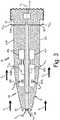
- FIG. 2is a perspective view of air data probe 16 and shows probe head 18, strut 20, baseplate 22, can 24, communication ports 26, body 28, tip 30, first and second outer wall regions 32A and 32B, total pressure ("PT") port 34, first alpha port 36A, first total pressure drain port 38A, and first alpha drain port 40A.
- PTtotal pressure
- FIG. 2the orientation of air data probe 16 has been rotated 90 degrees about an axis of body 28 as compared to the orientation of air data probe 16 shown in FIG. 1 .
- air data probe 16also has a second set of ports including second alpha port 36B, second total pressure drain port 38B, and second alpha drain port 40B on an opposite side of body 28, which are shown in FIG. 3 and will be discussed in conjunction with FIG. 3 .
- Probe head 18is a tubular object and is the sensing head of air data probe 16. Probe head 18 has one or more ports positioned in probe head 18 (see e.g., FIG. 3 ). In this non-limiting embodiment, probe head 18 is cylindrically shaped with a gradual taper. In this non-limiting embodiment, strut 20 is a hollow, blade-shaped housing or casing. In one non-limiting embodiment, strut 20 can be a casting. Baseplate 22 is a circular or elliptical disk of solid material that can include holes. Can 24 is a cylindrically shaped mounting canister, housing, or container that contains pressure sensors and electronic circuitry. In other non-limiting embodiments, air data probe 16 may not include can 24. Communication ports 26 include electrical contacts for providing electrical connection to the electronic circuitry within can 24.
- Body 28is a tube including a series of internal chambers that are disposed within first and second outer wall regions 32A and 32B.
- body 28includes a generally tubular shape with a gradual taper towards tip 30 and a barrel portion between tip 30 and strut 20.
- Tip 30is a distal end of body 28 that is on an opposite end of body 28 from strut 20.
- First and second outer wall regions 32A and 32Bform an exterior boundary of body 28.
- PT port 34 and first alpha port 36Aare fluidic inlets.
- body 28includes PT port 34 and first alpha port 36A.
- body 28can include more or less inlet ports than PT port 34 and first alpha port 36A.
- PT port 34is a total pressure port also known as an impact pressure port or a pitot pressure port.
- First alpha port 36Ais an alpha port and is also known as a static pressures port or an angle-of-attack port.
- First total pressure drain port 38A and first alpha drain port 40Aare water drain ports or fluidic outlets.
- body 28includes first total pressure drain port 38A and first alpha drain port 40A.
- body 28can include more or less outlet ports than first total pressure drain port 38A and first alpha drain port 40A.
- Air data probe 16is installed on aircraft 10, as shown in FIG. 1 . Internal components, such as sensors or other electronics, of air data probe 16 can be located within portions of probe head 18, strut 20, and/or can 24. Probe head 18 is connected to a first end of strut 20. Probe head 18 extends into an ambient environment disposed externally from and that surrounds aircraft 10 and air data probe 16. In this non-limiting embodiment, probe head 18 is aligned with a direction of airflow across air data probe 16, shown as generally left-to-right in FIGS. 1 , 2 and 3 . A second end of strut 20 is connected to can 24. As such, strut 20 connects probe head 18 to can 24. Baseplate 22 is positioned and connected between strut 20 and can 24.
- Baseplateconnects and attaches air data probe 16 to aircraft 10.
- can 24attaches to and is set into a portion of bottom surface 14 of aircraft 10.
- Communication ports 16form an electrical connection and communicate with corresponding communication ports located in the portion of aircraft 10 where air data probe 16 is installed.
- Body 28is attached and fluidly connected to a portion of strut 20.
- body 28is oriented such that tip 30 of body 28 points towards an upstream direction of body 28.
- First and second outer wall regions 32A and 32Bare disposed along a radially outward edge of body 28.
- Body 28 and its componentsare housed and contained by first and second outer wall regions 32A and 32B.
- Centerline axis Acextends through a radial center of body 28.
- PT port 34 and first alpha port 36Aare disposed in first and second outer wall regions 32A and 32B of body 28.
- PT port 34is disposed in tip 30 of body 28 and is fluidly connected to total pressure chamber 44.
- PT port 34is aligned collinear with centerline axis Ac of body 28.
- First alpha port 36Ais disposed in first outer wall region 32A of body 28 at a location positioned downstream of PT port 34 and upstream of strut 20.
- first alpha port 36Ais disposed axially along first outer wall region 32A between PT port 34 and first alpha drain port 40A.
- First alpha port 36A, first total pressure drain port 38A, and first alpha drain port 40Aare disposed in first outer wall region 32A of body 28.
- second alpha port 36B, second total pressure drain port 38B, and second alpha drain port 40Bare disposed in second outer wall region 32B of body 28.
- Air data probe 16uses the pressure measurements to generate air data parameters related to the aircraft flight conditions, such as the speed, altitude, angle-of-sideslip, or angle-of-attack of the aircraft.
- air data probe 16includes an angle-of-attack sensor configured to calculate an angle-of-attack of air data probe 16 so as to calculate an angle-of-attack of aircraft 10.
- Probe head 18takes in air from surrounding airflow via the one or more ports positioned in probe head 18. Air pressures from probe head 18 are communicated pneumatically through internal components of probe head 18 and strut 20 to reach internal components within can 24. Strut 20 holds probe head 18 away from fuselage 12 of aircraft 10 to expose probe head 18 to the oncoming airflow outside of a boundary layer flow along a surface of aircraft 10.
- Can 24can house pressure sensors and electronics.
- Can 24provides an anchoring functionality for attaching air data probe 16 to aircraft 10 by way of setting into a depressed portion or receptacle in aircraft 10 that is shaped to receive can 24.
- Pressure sensors and/or other components within can 24, or elsewhere in aircraft 10,measure the air pressures provided by probe head 18.
- FIG. 3is a cross-section view of probe head 18 taken along 3-3 in FIG. 2 and shows air data probe 16, probe head 18 (with body 28, tip 30, first and second outer wall regions 32A and 32B, centerline axis AC, total pressure ("PT") port 34, first and second alpha ports 36A and 36B, first and second total pressure drain ports 38A and 38B, first and second alpha drain ports 40A and 40B, interior walls 42, total pressure chamber 44, first and second alpha chambers 46A and 46B, first and second alpha pressure sensors 48A and 48B, and pitot pressure sensor 50), and strut 20.
- Arrowsillustrate ambient flow FA, total pressure flow FP, alpha flows FFA and FFB, total pressure water flows WPA and WPB, and alpha water flows W1A and W1B.
- Centerline axis ACis a straight imaginary line extending through a radial center of body 28.
- Interior walls 42are barriers or partitions of solid material.
- Total pressure chamber 44 and first and second alpha chambers 46A and 46Bare fluidic channels or passageways.
- body 28includes total pressure chamber 44 and first and second alpha chambers 46A and 46B.
- body 28can include more or less inlet ports than total pressure chamber 44 and first and second alpha chambers 46A and 46B.
- First and second alpha pressure sensors 48A and 48B and pitot pressure sensor 50are devices that detect or measure air pressure.
- Ambient flow FA, total pressure flow FP, and alpha flows FFA and FFBare flows of fluid such as air (or a combination of air and liquid, such as water).
- Fluidsuch as air (or a combination of air and liquid, such as water).
- Total pressure water flows WPA and WPB and alpha water flows W1A and W1Bare drainage flows of water.
- First and second total pressure drain ports 38A and 38Bare fluidly connected to total pressure chamber 44.
- first and second total pressure drain ports 38A and 38Bare positioned downstream of first and second alpha drain ports 40A and 40B and upstream of strut 20.
- First and second alpha drain ports 40A and 40Bare fluidly connected to first and second alpha chambers 46A and 46B, respectively.
- first and second alpha drain ports 40A and 40Bare positioned upstream of first and second total pressure drain ports 38A and 38B, respectively and upstream of strut 20.
- first and second alpha drain ports 40A and 40Bare disposed axially between first and second total pressure drain ports 38A and 38B and alpha inlet ports 36A and 36B, respectively.
- Interior walls 42are disposed in an interior of body 28. Interior walls 42 surround portions of total pressure chamber 44 and first and second alpha chambers 46A and 46B.
- Total pressure chamber 44is fluidly connected to PT port 34, to first and second total pressure drain ports 38A and 38B, and to pitot pressure sensor 50.
- First and second alpha chambers 46A and 46Bare fluidly connected to alpha inlet ports 36A and 36B, to alpha drain ports 42A and 42B, and to first and second alpha pressure sensors 48A and 48B, respectively.
- each of first and second alpha chambers 46A and 46Bare singular chambers.
- first and second alpha chambers 46A and 46Bcan include one or more fluidly separated chambers.
- total pressure chamber 44 and first and second alpha chambers 46A and 46Bare collinear with centerline axis AC and are coaxial with body 28.
- First and second alpha pressure sensors 48A and 48Bare disposed in body 28 and are in fluid communication with first and second alpha chambers 46A and 46B, respectively.
- pitot pressure sensor 50is disposed in strut 20 and is in fluid communication with total pressure chamber 44.
- Ambient flow FAis disposed exterior to body 28. Ambient flow FA is in fluid communication with PT port 34, first and second alpha ports 36A and 36B, first and second total pressure drain ports 38A and 38B, and first and second alpha drain ports 40A and 40B.
- Total pressure flow FPis a portion of ambient flow FA that enters into body 28 through PT port 34.
- Total pressure flow FPis disposed in total pressure chamber 44.
- Alpha flows FFA and FFBare portions of ambient flow FA that enter into body 28 through first and second alpha ports 36A and 36B. Alpha flows FFA and FFB are disposed in first and second alpha chambers 46A and 46B.
- Total pressure water flows WPA and WPB and alpha water flows W1A and W1Bare portions of total pressure flow FP and alpha flows FFA and FFB, respectively, that are ejected from body 28 via total pressure drain port 36 and first and second alpha drain ports 40A and 40B, respectively.
- air data probe 16is configured to sense changes in pressure in an environment surrounding body 28 of air data probe 16.
- PT port 34functions as the pitot source for air data probe 16.
- First and second alpha ports 36A and 36Bfunction as static pressure sources for air data probe 16.
- First and second total pressure drain ports 38A and 38B and first and second alpha drain ports 40A and 40Ballow ingested water to drain out of total pressure chamber 44 and first and second alpha chambers 46A and 46B, respectively.
- Interior walls 42fluidly separate and compartmentalize total pressure chamber 44 and alpha chamber 46 from each other. Interior walls 42 also define physical boundaries for total pressure port 34 and first and second alpha drain ports 40A and 40B.
- Total pressure chamber 44transports total pressure flow FP to pitot pressure sensor 50 so that total pressure flow FP can be used to measure pressure differentials between total pressure flow FP and alpha flows FFA and FFB in order to calculate air data parameters.
- first and second alpha chambers 46A and 46Btransport alpha flows FFA and FFB respectively to first and second alpha pressure sensors 48A and 48B.
- Ambient flow FAprovides body 28 with sources of air from which to measure pressure differentials and calculate air data parameters.
- Total pressure flow FP and alpha flows FFA and FFBare guided into first and second alpha pressure sensors 48A and 48B and pitot pressure sensor 50 by interior walls 42.
- Components within strut 20, can 24, and/or aircraft 10measure differential pressure changes between total pressure flow FP and alpha flows FFA and FFB.
- the measurements of differential pressure changes between total pressure flow FP and alpha flows FFA and FFBare then used to calculate air data parameters of aircraft 10 such as speed, altitude, angle-of-sideslip, and angle-of-attack.
- Total pressure water flows WPA and WPB and alpha water flows W1A and W1Bare removed via ejection/discharging from body 28 of air data probe 16.
- the means of drainage of total pressure water flows WPA and WPB and alpha water flows W1A and W1Bis by creating a pressure gradient between the sensing ports and the drainage ports, with the sensor ports including PT port 34 and first and second alpha ports 36A and 36B and the drainage ports including first and second total pressure drain ports 38A and 38B and first and second alpha drain ports 40A and 40B.
- alpha water flows W1A and W1Bare discharged from alpha chamber 46 in response to a pressure differential between alpha chamber 46 and the ambient environment.
- total pressure water flows WPA and WPBare discharged from total pressure chamber 44 in response to a pressure differential between total pressure chamber 44 and the ambient environment.
- First and second total pressure drain ports 38A and 38B and first and second alpha drain ports 40A and 40Ballow ingested water to drain out of probe head 18 while minimally impacting the sensitivity of the static pressure measurement by air data probe 16 in order to calculate air data parameters such as speed, altitude, and angle-of-attack.
Landscapes
- Physics & Mathematics (AREA)
- General Physics & Mathematics (AREA)
- Engineering & Computer Science (AREA)
- Aviation & Aerospace Engineering (AREA)
- Fluid Mechanics (AREA)
- Measuring Fluid Pressure (AREA)
Description
- The present disclosure relates generally to air data probes, and in particular, to management of liquid during use of air data probes.
- Air data probes are installed on aircraft to gather pneumatic pressures that permit the measurement of air data parameters. Air data probes sample air pressure, at one or more locations along a probe head, to permit measurement of pressures for generating air data parameters such as speed, altitude, and angle-of-attack.
- In particular, pitot-static style air data probes are susceptible to water ingestion in rain conditions and in warm supercooled liquid water conditions. Water ingestion into pitot-style air data probes can cause large induced pressure errors that influence the calculation of the air data parameters. Water management in these conditions is difficult due to competing requirements of preventing complete blockage of the sense-line (pressure tube) and the ability to quickly purge water from the sense lines and ports after exiting the icing or rain condition.
- An air data probe is known from
EP 3 076 185 A1WO 91/09274 - According to an aspect, there is provided an air data probe for use with an aircraft as recited in claim 1.
- Further, optional features are recited in each of claims 2 to 7.
- According to an aspect, there is provided a method of removing liquid from an air data probe of an aircraft as recited in claim 8.
- Further, optional steps and/or features are known from each of claims 9 to 13.
FIG. 1 is a perspective view of a portion of an aircraft with an air data probe.FIG. 2 is a perspective view of the air data probe.FIG. 3 is a cross-section view taken along 3-3 inFIG. 2 of a probe head of the air data probe.- For an aircraft angle-of-attack sensor, a probe barrel of the sensor includes a pair of ports on opposing ends of the barrel, with a first static inlet port (or ports) on one end and an outlet or drainage port (or ports) at a different location to provide a drainage path for water impinging on the inlet ports in order to minimize the impact on measured pressures and consequently on calculated angle-of-attack.
FIG. 1 shows a partial perspective view ofaircraft 10 and showsfuselage 12,bottom surface 14, andair data probe 16.Aircraft 10 is an airplane. In other non-limiting embodiments,aircraft 10 could also be other types of fixed-wing or rotorcraft such as propeller aircraft, jet aircraft, or helicopters.Fuselage 12 is a main body section ofaircraft 10.Bottom surface 14 is a surface along the bottom ofaircraft 10.Air data probe 16 is a pitot-static pneumatic angle-of-attack sensor (i.e., pneumatic pitot-tube sensor).Bottom surface 14 is connected and attached tofuselage 12 ofaircraft 10.Air data probe 16 is physically connected to and located alongbottom surface 14 ofaircraft 10. In one non-limiting embodiment,air data probe 16 may be mounted tofuselage 12 ofaircraft 10 via fasteners, such as screws or bolts. In other non-limiting embodiments,air data probe 16 can be attached toaircraft 10 at any location alongaircraft 10.Air data probe 16 extends frombottom surface 14 ofaircraft 10 and into an ambient environment that is exterior to and that surroundsaircraft 10. In this non-limiting environment,air data probe 16 points into an upstream direction (to the left inFIG. 1 ) relative to an intended direction of flight of the aircraft (to the left inFIG. 1 ). Correspondingly, asaircraft 10 is moving in the right-to-left upstream direction during flight, the ambient environment is moving in a downstream direction (left-to-right inFIG. 1 ) relative toaircraft 10.Air data probe 16 samples pneumatic pressures, at one or more locations alongair data probe 16, to permit measurement of pressures for generating air data parameters such as speed, altitude, angle-of-sideslip, and angle-of-attack. In this non-limiting embodiment,air data probe 16 is configured to calculate an air data parameter ofaircraft 10. Also in this non-limiting embodiment,air data probe 16 is configured to sense changes in pressure in an ambient environment surroundingair data probe 16.Air data probe 16 is susceptible to water ingestion in rain conditions and in warm supercooled liquid water conditions. Water ingestion intoair data probe 16 can cause large induced pressure errors that influence the calculation of the measured air data parameters. As will be discussed with respect toFIGS. 2 and3 , the configuration ofair data probe 16 helps to manage impinged water out of theair data probe 16 and away from pressure sense lines and assists with quickly purging water from the pressure sense lines and ports after exiting the icing or rain condition. As such, the configuration ofair data probe 16 minimizes the impact of ingested water on measured pressures and consequently calculated angle-of-attack ofaircraft 10.FIG. 2 is a perspective view ofair data probe 16 and showsprobe head 18,strut 20,baseplate 22, can 24,communication ports 26,body 28,tip 30, first and secondouter wall regions port 34,first alpha port 36A, first totalpressure drain port 38A, and firstalpha drain port 40A. InFIG. 2 , the orientation ofair data probe 16 has been rotated 90 degrees about an axis ofbody 28 as compared to the orientation ofair data probe 16 shown inFIG. 1 . In this non-limiting embodiment,air data probe 16 also has a second set of ports includingsecond alpha port 36B, second totalpressure drain port 38B, and secondalpha drain port 40B on an opposite side ofbody 28, which are shown inFIG. 3 and will be discussed in conjunction withFIG. 3 .Probe head 18 is a tubular object and is the sensing head ofair data probe 16.Probe head 18 has one or more ports positioned in probe head 18 (see e.g.,FIG. 3 ). In this non-limiting embodiment,probe head 18 is cylindrically shaped with a gradual taper. In this non-limiting embodiment,strut 20 is a hollow, blade-shaped housing or casing. In one non-limiting embodiment,strut 20 can be a casting.Baseplate 22 is a circular or elliptical disk of solid material that can include holes. Can 24 is a cylindrically shaped mounting canister, housing, or container that contains pressure sensors and electronic circuitry. In other non-limiting embodiments,air data probe 16 may not include can 24.Communication ports 26 include electrical contacts for providing electrical connection to the electronic circuitry within can 24.Body 28 is a tube including a series of internal chambers that are disposed within first and secondouter wall regions body 28 includes a generally tubular shape with a gradual taper towardstip 30 and a barrel portion betweentip 30 andstrut 20.Tip 30 is a distal end ofbody 28 that is on an opposite end ofbody 28 fromstrut 20. First and secondouter wall regions body 28.PT port 34 andfirst alpha port 36A are fluidic inlets. In this non-limiting embodiment,body 28 includesPT port 34 andfirst alpha port 36A. In other non-limiting embodiment,body 28 can include more or less inlet ports thanPT port 34 andfirst alpha port 36A. PTport 34 is a total pressure port also known as an impact pressure port or a pitot pressure port.First alpha port 36A is an alpha port and is also known as a static pressures port or an angle-of-attack port.- First total
pressure drain port 38A and firstalpha drain port 40A are water drain ports or fluidic outlets. In this non-limiting embodiment,body 28 includes first totalpressure drain port 38A and firstalpha drain port 40A. In other non-limiting embodiment,body 28 can include more or less outlet ports than first totalpressure drain port 38A and firstalpha drain port 40A. Air data probe 16 is installed onaircraft 10, as shown inFIG. 1 . Internal components, such as sensors or other electronics, ofair data probe 16 can be located within portions ofprobe head 18,strut 20, and/or can 24.Probe head 18 is connected to a first end ofstrut 20.Probe head 18 extends into an ambient environment disposed externally from and that surroundsaircraft 10 andair data probe 16. In this non-limiting embodiment,probe head 18 is aligned with a direction of airflow acrossair data probe 16, shown as generally left-to-right inFIGS. 1 ,2 and3 . A second end ofstrut 20 is connected tocan 24. As such, strut 20 connectsprobe head 18 tocan 24.Baseplate 22 is positioned and connected betweenstrut 20 and can 24. Baseplate connects and attachesair data probe 16 toaircraft 10. In one non-limiting embodiment, can 24 attaches to and is set into a portion ofbottom surface 14 ofaircraft 10.Communication ports 16 form an electrical connection and communicate with corresponding communication ports located in the portion ofaircraft 10 whereair data probe 16 is installed.Body 28 is attached and fluidly connected to a portion ofstrut 20. In this non-limiting embodiment,body 28 is oriented such thattip 30 ofbody 28 points towards an upstream direction ofbody 28. For example, as aircraft 10 (shown inFIG. 1 ) moves during flight,body 28 moves in an upstream direction (right-to-left inFIG. 2 ). First and secondouter wall regions body 28.Body 28 and its components are housed and contained by first and secondouter wall regions body 28.PT port 34 andfirst alpha port 36A are disposed in first and secondouter wall regions body 28.PT port 34 is disposed intip 30 ofbody 28 and is fluidly connected tototal pressure chamber 44. In this non-limiting embodiment,PT port 34 is aligned collinear with centerline axis Ac ofbody 28.First alpha port 36A is disposed in firstouter wall region 32A ofbody 28 at a location positioned downstream ofPT port 34 and upstream ofstrut 20. In this non-limiting embodiment,first alpha port 36A is disposed axially along firstouter wall region 32A betweenPT port 34 and firstalpha drain port 40A.First alpha port 36A, first totalpressure drain port 38A, and firstalpha drain port 40A are disposed in firstouter wall region 32A ofbody 28. As will be shown inFIG. 3 ,second alpha port 36B, second totalpressure drain port 38B, and secondalpha drain port 40B are disposed in secondouter wall region 32B ofbody 28.Air data probe 16 uses the pressure measurements to generate air data parameters related to the aircraft flight conditions, such as the speed, altitude, angle-of-sideslip, or angle-of-attack of the aircraft. In one non-limiting embodiment,air data probe 16 includes an angle-of-attack sensor configured to calculate an angle-of-attack ofair data probe 16 so as to calculate an angle-of-attack ofaircraft 10.Probe head 18 takes in air from surrounding airflow via the one or more ports positioned inprobe head 18. Air pressures fromprobe head 18 are communicated pneumatically through internal components ofprobe head 18 and strut 20 to reach internal components withincan 24.Strut 20 holdsprobe head 18 away fromfuselage 12 ofaircraft 10 to exposeprobe head 18 to the oncoming airflow outside of a boundary layer flow along a surface ofaircraft 10. Can 24 can house pressure sensors and electronics. Can 24 provides an anchoring functionality for attachingair data probe 16 toaircraft 10 by way of setting into a depressed portion or receptacle inaircraft 10 that is shaped to receivecan 24. Pressure sensors and/or other components withincan 24, or elsewhere inaircraft 10, measure the air pressures provided byprobe head 18.FIG. 3 is a cross-section view ofprobe head 18 taken along 3-3 inFIG. 2 and showsair data probe 16, probe head 18 (withbody 28,tip 30, first and secondouter wall regions port 34, first andsecond alpha ports pressure drain ports alpha drain ports interior walls 42,total pressure chamber 44, first andsecond alpha chambers alpha pressure sensors - Centerline axis AC is a straight imaginary line extending through a radial center of
body 28.Interior walls 42 are barriers or partitions of solid material.Total pressure chamber 44 and first andsecond alpha chambers body 28 includestotal pressure chamber 44 and first andsecond alpha chambers body 28 can include more or less inlet ports thantotal pressure chamber 44 and first andsecond alpha chambers alpha pressure sensors pitot pressure sensor 50 are devices that detect or measure air pressure. Ambient flow FA, total pressure flow FP, and alpha flows FFA and FFB are flows of fluid such as air (or a combination of air and liquid, such as water). Total pressure water flows WPA and WPB and alpha water flows W1A and W1B are drainage flows of water. - First and second total
pressure drain ports total pressure chamber 44. In this non-limiting embodiment, first and second totalpressure drain ports alpha drain ports strut 20. First and secondalpha drain ports second alpha chambers alpha drain ports pressure drain ports strut 20. In this non-limiting embodiment, first and secondalpha drain ports pressure drain ports alpha inlet ports Interior walls 42 are disposed in an interior ofbody 28.Interior walls 42 surround portions oftotal pressure chamber 44 and first andsecond alpha chambers Total pressure chamber 44 is fluidly connected toPT port 34, to first and second totalpressure drain ports pitot pressure sensor 50. First andsecond alpha chambers alpha inlet ports alpha pressure sensors second alpha chambers second alpha chambers total pressure chamber 44 and first andsecond alpha chambers body 28. First and secondalpha pressure sensors body 28 and are in fluid communication with first andsecond alpha chambers pitot pressure sensor 50 is disposed instrut 20 and is in fluid communication withtotal pressure chamber 44.- Ambient flow FA is disposed exterior to
body 28. Ambient flow FA is in fluid communication withPT port 34, first andsecond alpha ports pressure drain ports alpha drain ports body 28 throughPT port 34. Total pressure flow FP is disposed intotal pressure chamber 44. Alpha flows FFA and FFB are portions of ambient flow FA that enter intobody 28 through first andsecond alpha ports second alpha chambers body 28 via total pressure drain port 36 and first and secondalpha drain ports - In this non-limiting embodiment,
air data probe 16 is configured to sense changes in pressure in anenvironment surrounding body 28 ofair data probe 16.PT port 34 functions as the pitot source forair data probe 16. First andsecond alpha ports air data probe 16. First and second totalpressure drain ports alpha drain ports total pressure chamber 44 and first andsecond alpha chambers Interior walls 42 fluidly separate and compartmentalizetotal pressure chamber 44 and alpha chamber 46 from each other.Interior walls 42 also define physical boundaries fortotal pressure port 34 and first and secondalpha drain ports Total pressure chamber 44 transports total pressure flow FP topitot pressure sensor 50 so that total pressure flow FP can be used to measure pressure differentials between total pressure flow FP and alpha flows FFA and FFB in order to calculate air data parameters. Likewise, first andsecond alpha chambers alpha pressure sensors - Ambient flow FA provides
body 28 with sources of air from which to measure pressure differentials and calculate air data parameters. Total pressure flow FP and alpha flows FFA and FFB are guided into first and secondalpha pressure sensors pitot pressure sensor 50 byinterior walls 42. Components withinstrut 20, can 24, and/oraircraft 10 measure differential pressure changes between total pressure flow FP and alpha flows FFA and FFB. The measurements of differential pressure changes between total pressure flow FP and alpha flows FFA and FFB are then used to calculate air data parameters ofaircraft 10 such as speed, altitude, angle-of-sideslip, and angle-of-attack. Total pressure water flows WPA and WPB and alpha water flows W1A and W1B are removed via ejection/discharging frombody 28 ofair data probe 16. - The means of drainage of total pressure water flows WPA and WPB and alpha water flows W1A and W1B is by creating a pressure gradient between the sensing ports and the drainage ports, with the sensor ports including
PT port 34 and first andsecond alpha ports pressure drain ports alpha drain ports total pressure chamber 44 in response to a pressure differential betweentotal pressure chamber 44 and the ambient environment. - In existing air data probes with angle-of-attack sensors, the static ports are directly connected to a sensing chamber within the housing with no drainage ports. First and second total
pressure drain ports alpha drain ports probe head 18 while minimally impacting the sensitivity of the static pressure measurement byair data probe 16 in order to calculate air data parameters such as speed, altitude, and angle-of-attack. - While the invention has been described with reference to an exemplary embodiment(s), it will be understood by those skilled in the art that various changes may be made and equivalents may be substituted for elements thereof without departing from the scope of the invention. In addition, many modifications may be made to adapt a particular situation or material to the teachings of the invention without departing from the scope thereof. Therefore, it is intended that the invention not be limited to the particular embodiment(s) disclosed, but that the invention will include all embodiments falling within the scope of the appended claims.
Claims (13)
- An air data probe (16) for use with an aircraft (10), the air data probe comprising:a housing; anda probe head (18) attached to the housing, wherein the probe head further comprises:a body (28) connected to and extending from the housing, wherein the body comprises an outer wall region (32A, 32B) and a tubular shape, wherein the body is connected to the housing at a downstream end of the body;a total pressure port (34) disposed in a distal end of the body opposite from the housing, wherein the distal end of the body opposite from the housing comprises an upstream end of the body, wherein the total pressure port is aligned collinear with a centerline axis of the body;a total pressure chamber (44) extending through a radial center of the body, wherein the total pressure chamber is in fluid communication with the total pressure port and with the housing;a first alpha port (36A) disposed in the body at a location positioned downstream of the total pressure port and upstream of the housing;a first alpha chamber (46A) extending through a portion of the body, wherein the first alpha chamber is in fluid communication with the first alpha port, wherein the first alpha chamber is disposed radially outward from the total pressure chamber;a second alpha port (36B) disposed in the body at a location positioned downstream of the total pressure port and upstream of the housing;a second alpha chamber (46B) extending through the body, wherein the second alpha chamber is in fluid communication with the second alpha port, wherein the second alpha chamber is disposed radially outward from the total pressure chamber;characterised bya first alpha drain port (40A) disposed in the body at a location positioned downstream from the first alpha port and upstream from the housing, wherein the first alpha drain port is in fluid communication with the first alpha chamber;a second alpha drain port (40B) disposed in the body at a location positioned downstream from the second alpha port and upstream from the housing, wherein the second alpha drain port is in fluid communication with the second alpha chamber; anda total pressure drain port (38A, 38B) disposed in the body of the probe head, wherein the total pressure drain port is fluidly connected to the total pressure chamber, and wherein the total pressure drain port is configured to drain liquid from the total pressure chamber of the body to outside of the body.
- The air data probe (16) of claim 1, wherein the air data probe comprises an angle-of-attack sensor configured to calculate an angle between the air data probe and a direction of a flow of fluid flowing across the air data probe.
- The air data probe (16) of claim 1 or 2, wherein the air data probe comprises a pneumatic pitot-tube sensor configured to sense changes in pressure in an environment surrounding the body (28) of the air data probe, wherein, optionally, the total pressure port (34) is configured to take in fluid from an ambient environment external to the air data probe and through which the aircraft is moving relative to.
- The air data probe (16) of claim 1, 2 or 3, wherein the first alpha drain port (40A) is configured to drain liquid from the first alpha chamber (46A) of the body (28) to outside of the body, wherein the second alpha drain port (40B) is configured to drain liquid from the second alpha chamber (46B) of the body to outside of the body.
- The air data probe (16) of any preceding claim, wherein the total pressure drain port (38A, 38B) is disposed in the body (28) at a location positioned downstream from the total pressure port (34) and upstream from the housing, wherein the total pressure drain port is in fluid communication with the total pressure chamber (44).
- The air data probe (16) of any preceding claim, wherein the air data probe is configured to discharge liquid from the first alpha chamber (46A) in response to a pressure differential between the first alpha chamber and an ambient environment.
- The air data probe (16) of any preceding claim, wherein the air data probe is configured to discharge liquid from the total pressure chamber (44) in response to a pressure differential between the total pressure chamber and an ambient environment.
- A method of removing liquid from an air data probe (16) of an aircraft (10), the method comprising:moving the air data probe of the aircraft relative to an ambient environment that is external to the air data probe, wherein the air data probe comprises:a housing; anda probe head (18) attached to the housing, wherein the probe head further comprises:a body (28) connected to and extending from the housing, wherein the body comprises an outer wall region (32A, 32B) and a tubular shape, wherein body is connected to the housing at downstream end of the body;a total pressure port (34) disposed in a distal end of the body opposite from the housing, wherein the distal end of the body opposite from the housing comprises an upstream end of the body, wherein the total pressure port is aligned collinear with a centerline axis of the body;a total pressure chamber (44) extending through a radial center of the body, wherein the total pressure chamber is in fluid communication with the total pressure port and with the housing;a first alpha port (36A) disposed in the body at a location positioned downstream of the total pressure port and upstream of the housing;a first alpha chamber (46A) extending through the body, wherein the first alpha chamber is in fluid communication with the first alpha port, wherein the first alpha chamber is disposed radially outward from the total pressure chamber;a second alpha port (36B) disposed in the body at a location positioned downstream of the total pressure port and upstream of the housing;a second alpha chamber (46B) extending through the body, wherein the second alpha chamber is in fluid communication with the second alpha port, wherein the second alpha chamber is disposed radially outward from the total pressure chamber;characterised bya first alpha drain port (40A) disposed in the body at a location positioned downstream from the first alpha port and upstream from the housing, wherein the first alpha drain port is in fluid communication with the first alpha chamber;a second alpha drain port (40B) disposed in the body at a location positioned downstream from the second alpha port and upstream from the housing, wherein the second alpha drain port is in fluid communication with the second alpha chamber;a total pressure drain port (38A, 38B) disposed in the body at a location positioned downstream from the total pressure port and upstream from the housing, wherein the total pressure drain port is in fluid communication with the total pressure chamber; anddischarging liquid from the first alpha chamber out of the first alpha drain port and into the ambient environment.
- The method of claim 8, further comprising discharging liquid from the total pressure chamber (44) out of the total pressure drain port (38A, 38B) and into the ambient environment.
- The method of claim 8 or 9, further comprising sensing a change in pressure of a fluid in the air data probe (16), optionally further comprising calculating an angle-of-attack of the air data probe based on the sensed change in pressure.
- The method of claim 8, 9 or 10, wherein a downstream direction includes a direction of flow of the ambient environment relative to the air data probe (16) of the aircraft, wherein the first alpha drain port (40A) is located downstream of the alpha port (36A).
- The method of any of claims 8 to 11, wherein the liquid is discharged from the first alpha chamber (46A) in response to a pressure differential between the first alpha chamber and the ambient environment.
- The method of any of claims 8 to 12, wherein liquid is discharged from the total pressure chamber (44) in response to a pressure differential between the total pressure chamber and an ambient environment.
Applications Claiming Priority (1)
| Application Number | Priority Date | Filing Date | Title |
|---|---|---|---|
| US15/974,975US10564173B2 (en) | 2018-05-09 | 2018-05-09 | Pitot-static probe with pneumatic angle-of-attack sensor |
Publications (2)
| Publication Number | Publication Date |
|---|---|
| EP3567379A1 EP3567379A1 (en) | 2019-11-13 |
| EP3567379B1true EP3567379B1 (en) | 2022-07-06 |
Family
ID=66476538
Family Applications (1)
| Application Number | Title | Priority Date | Filing Date |
|---|---|---|---|
| EP19173597.6AActiveEP3567379B1 (en) | 2018-05-09 | 2019-05-09 | Pitot-static probe with pneumatic angle-of-attack sensor |
Country Status (2)
| Country | Link |
|---|---|
| US (1) | US10564173B2 (en) |
| EP (1) | EP3567379B1 (en) |
Families Citing this family (8)
| Publication number | Priority date | Publication date | Assignee | Title |
|---|---|---|---|---|
| US10823751B2 (en)* | 2018-08-17 | 2020-11-03 | Rosemount Aerospace Inc. | Aircraft probe with removable and replaceable embedded electronics |
| US10823753B2 (en)* | 2018-12-14 | 2020-11-03 | Rosemount Aerospace Inc. | Air data probe with optical pressure integration |
| US11215631B2 (en) | 2019-10-16 | 2022-01-04 | Honeywell International Inc. | Multi-function air data probe having multi-hole ports used for determining angle of attack, total and static pressure values |
| US12339294B2 (en) | 2020-02-25 | 2025-06-24 | Rosemount Aerospace Inc. | Angle of attack sensor vane geometry |
| CN112630466B (en)* | 2020-12-03 | 2023-10-31 | 深圳市蜉飞科技有限公司 | Airspeed meter is with atmospheric pressure collection structure and fixed wing unmanned aerial vehicle |
| CN112407331A (en)* | 2020-12-15 | 2021-02-26 | 西安飞机工业(集团)有限责任公司 | Pressurizing device and pressurizing method suitable for atmospheric data computer probe |
| SE544928C2 (en)* | 2021-05-12 | 2023-01-10 | Isak Jonsson Ab | Multi-hole pressure probe and use of such a probe |
| US11579163B1 (en) | 2021-07-29 | 2023-02-14 | Rockwell Collins, Inc. | Differential pressure angle of attack sensor |
Family Cites Families (19)
| Publication number | Priority date | Publication date | Assignee | Title |
|---|---|---|---|---|
| US2204367A (en) | 1938-05-03 | 1940-06-11 | Square D Co | Trapped self-draining pitot-static tube |
| US5046360A (en) | 1989-12-15 | 1991-09-10 | Rosemount Inc. | Aerodynamic probe internal constructions |
| US5544526A (en) | 1994-06-30 | 1996-08-13 | Avionics Specialties, Inc. | Combined aircraft angle of attack and dynamic/static pressure sensor assembly |
| US6892584B2 (en)* | 2002-11-19 | 2005-05-17 | Rosemount Aerospace Inc. | Fabricated pitot probe assembly |
| FR2908882B1 (en)* | 2006-11-17 | 2008-12-26 | Thales Sa | DEVICE FOR MEASURING THE TOTAL PRESSURE OF A FLOW AND METHOD USING THE DEVICE |
| WO2013028220A1 (en) | 2011-08-19 | 2013-02-28 | Aerovironment Inc. | Water resisitant aircraft pitot device |
| GB201213576D0 (en)* | 2012-07-31 | 2012-09-12 | Rolls Royce Plc | Total temperature probe |
| EP2728364B1 (en) | 2012-10-31 | 2019-04-17 | Rosemount Aerospace Inc. | Ice resistant pitot tube |
| US9279684B2 (en) | 2013-04-02 | 2016-03-08 | Rosemount Aerospace Inc. | Air data probe sense port repair |
| US9027392B2 (en)* | 2013-05-07 | 2015-05-12 | Honeywell International Inc. | Multi-hole probes and methods for manufacturing multi-hole probes |
| FR3010190B1 (en)* | 2013-08-30 | 2016-12-02 | Thales Sa | AERODYNAMIC MEASUREMENT PROBE FOR AIRCRAFT |
| US10281303B2 (en)* | 2015-03-23 | 2019-05-07 | Rosemount Aerospace, Inc. | Air data probe with improved performance at angle of attack operation |
| US10227139B2 (en)* | 2015-03-23 | 2019-03-12 | Rosemount Aerospace Inc. | Heated air data probes |
| CA2919341C (en) | 2015-04-02 | 2022-11-15 | Rosemount Aerospace, Inc. | Corrosion-resistant heated air data probe |
| GB2541356A (en) | 2015-06-08 | 2017-02-22 | Meggitt (Uk) Ltd | Moving-vane angle of attack probe |
| US9696187B2 (en)* | 2015-07-01 | 2017-07-04 | Rosemount Aerospace Inc. | Device for measuring total pressure of fluid flow |
| US10126320B2 (en)* | 2017-03-13 | 2018-11-13 | Honeywell International Inc. | Arrangement of dams in air data probe |
| US11221346B2 (en)* | 2017-03-13 | 2022-01-11 | Honeywell International Inc. | Ice prevention dam for, and method for forming, a pitot tube |
| FR3067115B1 (en)* | 2017-06-02 | 2019-07-26 | Thales | PRESSURE MEASURING SENSOR, IN PARTICULAR FOR AN AIRCRAFT |
- 2018
- 2018-05-09USUS15/974,975patent/US10564173B2/enactiveActive
- 2019
- 2019-05-09EPEP19173597.6Apatent/EP3567379B1/enactiveActive
Also Published As
| Publication number | Publication date |
|---|---|
| US20190346476A1 (en) | 2019-11-14 |
| EP3567379A1 (en) | 2019-11-13 |
| US10564173B2 (en) | 2020-02-18 |
Similar Documents
| Publication | Publication Date | Title |
|---|---|---|
| EP3567379B1 (en) | Pitot-static probe with pneumatic angle-of-attack sensor | |
| JP4422907B2 (en) | Air temperature sensor integrated probe for aircraft | |
| US6941805B2 (en) | Multi-function air data sensing probe having an angle of attack vane | |
| EP2700952B1 (en) | Moisture resistant air data probes | |
| EP1918686B1 (en) | Flight air data measuring system | |
| EP3104179B1 (en) | Moving-vane angle of attack probe | |
| CN101558315B (en) | Device for measuring the total pressure of a flow and method using said device | |
| US7490510B2 (en) | Multi-function air data sensor | |
| EP0719416B1 (en) | Integral airfoil total temperature sensor | |
| EP1256812B1 (en) | Sideslip correction for a multi-function three probe air data system | |
| US11566892B2 (en) | Air data probe | |
| US8695412B2 (en) | Probe for measuring a local angle of attack and method implementing same | |
| US10203253B2 (en) | Total air temperature probe with efficient particle pass through | |
| CN111323161A (en) | Optical pressure integrated atmospheric data probe | |
| US9304020B2 (en) | Device for maintaining and analyzing an aerodynamic probe | |
| CN107110745B (en) | Insert for air inlet and outlet device | |
| GB2491167A (en) | Aircraft wing blister | |
| CN104969050A (en) | Total pressure and total temperature measurement in wet gas condition | |
| KR102002824B1 (en) | Flush port air data system of flying object | |
| KR20190086405A (en) | Flush port air data system of flying object |
Legal Events
| Date | Code | Title | Description |
|---|---|---|---|
| PUAI | Public reference made under article 153(3) epc to a published international application that has entered the european phase | Free format text:ORIGINAL CODE: 0009012 | |
| STAA | Information on the status of an ep patent application or granted ep patent | Free format text:STATUS: THE APPLICATION HAS BEEN PUBLISHED | |
| AK | Designated contracting states | Kind code of ref document:A1 Designated state(s):AL AT BE BG CH CY CZ DE DK EE ES FI FR GB GR HR HU IE IS IT LI LT LU LV MC MK MT NL NO PL PT RO RS SE SI SK SM TR | |
| AX | Request for extension of the european patent | Extension state:BA ME | |
| STAA | Information on the status of an ep patent application or granted ep patent | Free format text:STATUS: REQUEST FOR EXAMINATION WAS MADE | |
| 17P | Request for examination filed | Effective date:20191203 | |
| RBV | Designated contracting states (corrected) | Designated state(s):AL AT BE BG CH CY CZ DE DK EE ES FI FR GB GR HR HU IE IS IT LI LT LU LV MC MK MT NL NO PL PT RO RS SE SI SK SM TR | |
| GRAP | Despatch of communication of intention to grant a patent | Free format text:ORIGINAL CODE: EPIDOSNIGR1 | |
| STAA | Information on the status of an ep patent application or granted ep patent | Free format text:STATUS: GRANT OF PATENT IS INTENDED | |
| INTG | Intention to grant announced | Effective date:20220126 | |
| RAP3 | Party data changed (applicant data changed or rights of an application transferred) | Owner name:ROSEMOUNT AEROSPACE INC. | |
| GRAS | Grant fee paid | Free format text:ORIGINAL CODE: EPIDOSNIGR3 | |
| GRAA | (expected) grant | Free format text:ORIGINAL CODE: 0009210 | |
| STAA | Information on the status of an ep patent application or granted ep patent | Free format text:STATUS: THE PATENT HAS BEEN GRANTED | |
| AK | Designated contracting states | Kind code of ref document:B1 Designated state(s):AL AT BE BG CH CY CZ DE DK EE ES FI FR GB GR HR HU IE IS IT LI LT LU LV MC MK MT NL NO PL PT RO RS SE SI SK SM TR | |
| REG | Reference to a national code | Ref country code:AT Ref legal event code:REF Ref document number:1503225 Country of ref document:AT Kind code of ref document:T Effective date:20220715 Ref country code:CH Ref legal event code:EP | |
| REG | Reference to a national code | Ref country code:DE Ref legal event code:R096 Ref document number:602019016599 Country of ref document:DE | |
| REG | Reference to a national code | Ref country code:IE Ref legal event code:FG4D | |
| REG | Reference to a national code | Ref country code:LT Ref legal event code:MG9D | |
| REG | Reference to a national code | Ref country code:NL Ref legal event code:MP Effective date:20220706 | |
| PG25 | Lapsed in a contracting state [announced via postgrant information from national office to epo] | Ref country code:SE Free format text:LAPSE BECAUSE OF FAILURE TO SUBMIT A TRANSLATION OF THE DESCRIPTION OR TO PAY THE FEE WITHIN THE PRESCRIBED TIME-LIMIT Effective date:20220706 Ref country code:RS Free format text:LAPSE BECAUSE OF FAILURE TO SUBMIT A TRANSLATION OF THE DESCRIPTION OR TO PAY THE FEE WITHIN THE PRESCRIBED TIME-LIMIT Effective date:20220706 Ref country code:PT Free format text:LAPSE BECAUSE OF FAILURE TO SUBMIT A TRANSLATION OF THE DESCRIPTION OR TO PAY THE FEE WITHIN THE PRESCRIBED TIME-LIMIT Effective date:20221107 Ref country code:NO Free format text:LAPSE BECAUSE OF FAILURE TO SUBMIT A TRANSLATION OF THE DESCRIPTION OR TO PAY THE FEE WITHIN THE PRESCRIBED TIME-LIMIT Effective date:20221006 Ref country code:NL Free format text:LAPSE BECAUSE OF FAILURE TO SUBMIT A TRANSLATION OF THE DESCRIPTION OR TO PAY THE FEE WITHIN THE PRESCRIBED TIME-LIMIT Effective date:20220706 Ref country code:LV Free format text:LAPSE BECAUSE OF FAILURE TO SUBMIT A TRANSLATION OF THE DESCRIPTION OR TO PAY THE FEE WITHIN THE PRESCRIBED TIME-LIMIT Effective date:20220706 Ref country code:LT Free format text:LAPSE BECAUSE OF FAILURE TO SUBMIT A TRANSLATION OF THE DESCRIPTION OR TO PAY THE FEE WITHIN THE PRESCRIBED TIME-LIMIT Effective date:20220706 Ref country code:FI Free format text:LAPSE BECAUSE OF FAILURE TO SUBMIT A TRANSLATION OF THE DESCRIPTION OR TO PAY THE FEE WITHIN THE PRESCRIBED TIME-LIMIT Effective date:20220706 Ref country code:ES Free format text:LAPSE BECAUSE OF FAILURE TO SUBMIT A TRANSLATION OF THE DESCRIPTION OR TO PAY THE FEE WITHIN THE PRESCRIBED TIME-LIMIT Effective date:20220706 | |
| REG | Reference to a national code | Ref country code:AT Ref legal event code:MK05 Ref document number:1503225 Country of ref document:AT Kind code of ref document:T Effective date:20220706 | |
| PG25 | Lapsed in a contracting state [announced via postgrant information from national office to epo] | Ref country code:PL Free format text:LAPSE BECAUSE OF FAILURE TO SUBMIT A TRANSLATION OF THE DESCRIPTION OR TO PAY THE FEE WITHIN THE PRESCRIBED TIME-LIMIT Effective date:20220706 Ref country code:IS Free format text:LAPSE BECAUSE OF FAILURE TO SUBMIT A TRANSLATION OF THE DESCRIPTION OR TO PAY THE FEE WITHIN THE PRESCRIBED TIME-LIMIT Effective date:20221106 Ref country code:HR Free format text:LAPSE BECAUSE OF FAILURE TO SUBMIT A TRANSLATION OF THE DESCRIPTION OR TO PAY THE FEE WITHIN THE PRESCRIBED TIME-LIMIT Effective date:20220706 Ref country code:GR Free format text:LAPSE BECAUSE OF FAILURE TO SUBMIT A TRANSLATION OF THE DESCRIPTION OR TO PAY THE FEE WITHIN THE PRESCRIBED TIME-LIMIT Effective date:20221007 | |
| REG | Reference to a national code | Ref country code:DE Ref legal event code:R097 Ref document number:602019016599 Country of ref document:DE | |
| PG25 | Lapsed in a contracting state [announced via postgrant information from national office to epo] | Ref country code:SM Free format text:LAPSE BECAUSE OF FAILURE TO SUBMIT A TRANSLATION OF THE DESCRIPTION OR TO PAY THE FEE WITHIN THE PRESCRIBED TIME-LIMIT Effective date:20220706 Ref country code:RO Free format text:LAPSE BECAUSE OF FAILURE TO SUBMIT A TRANSLATION OF THE DESCRIPTION OR TO PAY THE FEE WITHIN THE PRESCRIBED TIME-LIMIT Effective date:20220706 Ref country code:DK Free format text:LAPSE BECAUSE OF FAILURE TO SUBMIT A TRANSLATION OF THE DESCRIPTION OR TO PAY THE FEE WITHIN THE PRESCRIBED TIME-LIMIT Effective date:20220706 Ref country code:CZ Free format text:LAPSE BECAUSE OF FAILURE TO SUBMIT A TRANSLATION OF THE DESCRIPTION OR TO PAY THE FEE WITHIN THE PRESCRIBED TIME-LIMIT Effective date:20220706 Ref country code:AT Free format text:LAPSE BECAUSE OF FAILURE TO SUBMIT A TRANSLATION OF THE DESCRIPTION OR TO PAY THE FEE WITHIN THE PRESCRIBED TIME-LIMIT Effective date:20220706 | |
| PLBE | No opposition filed within time limit | Free format text:ORIGINAL CODE: 0009261 | |
| STAA | Information on the status of an ep patent application or granted ep patent | Free format text:STATUS: NO OPPOSITION FILED WITHIN TIME LIMIT | |
| PG25 | Lapsed in a contracting state [announced via postgrant information from national office to epo] | Ref country code:SK Free format text:LAPSE BECAUSE OF FAILURE TO SUBMIT A TRANSLATION OF THE DESCRIPTION OR TO PAY THE FEE WITHIN THE PRESCRIBED TIME-LIMIT Effective date:20220706 Ref country code:EE Free format text:LAPSE BECAUSE OF FAILURE TO SUBMIT A TRANSLATION OF THE DESCRIPTION OR TO PAY THE FEE WITHIN THE PRESCRIBED TIME-LIMIT Effective date:20220706 | |
| 26N | No opposition filed | Effective date:20230411 | |
| PG25 | Lapsed in a contracting state [announced via postgrant information from national office to epo] | Ref country code:AL Free format text:LAPSE BECAUSE OF FAILURE TO SUBMIT A TRANSLATION OF THE DESCRIPTION OR TO PAY THE FEE WITHIN THE PRESCRIBED TIME-LIMIT Effective date:20220706 | |
| PG25 | Lapsed in a contracting state [announced via postgrant information from national office to epo] | Ref country code:SI Free format text:LAPSE BECAUSE OF FAILURE TO SUBMIT A TRANSLATION OF THE DESCRIPTION OR TO PAY THE FEE WITHIN THE PRESCRIBED TIME-LIMIT Effective date:20220706 | |
| REG | Reference to a national code | Ref country code:CH Ref legal event code:PL | |
| PG25 | Lapsed in a contracting state [announced via postgrant information from national office to epo] | Ref country code:MC Free format text:LAPSE BECAUSE OF FAILURE TO SUBMIT A TRANSLATION OF THE DESCRIPTION OR TO PAY THE FEE WITHIN THE PRESCRIBED TIME-LIMIT Effective date:20220706 | |
| REG | Reference to a national code | Ref country code:BE Ref legal event code:MM Effective date:20230531 | |
| PG25 | Lapsed in a contracting state [announced via postgrant information from national office to epo] | Ref country code:MC Free format text:LAPSE BECAUSE OF FAILURE TO SUBMIT A TRANSLATION OF THE DESCRIPTION OR TO PAY THE FEE WITHIN THE PRESCRIBED TIME-LIMIT Effective date:20220706 Ref country code:LU Free format text:LAPSE BECAUSE OF NON-PAYMENT OF DUE FEES Effective date:20230509 Ref country code:LI Free format text:LAPSE BECAUSE OF NON-PAYMENT OF DUE FEES Effective date:20230531 Ref country code:IT Free format text:LAPSE BECAUSE OF FAILURE TO SUBMIT A TRANSLATION OF THE DESCRIPTION OR TO PAY THE FEE WITHIN THE PRESCRIBED TIME-LIMIT Effective date:20220706 Ref country code:CH Free format text:LAPSE BECAUSE OF NON-PAYMENT OF DUE FEES Effective date:20230531 | |
| REG | Reference to a national code | Ref country code:IE Ref legal event code:MM4A | |
| PG25 | Lapsed in a contracting state [announced via postgrant information from national office to epo] | Ref country code:IE Free format text:LAPSE BECAUSE OF NON-PAYMENT OF DUE FEES Effective date:20230509 | |
| PG25 | Lapsed in a contracting state [announced via postgrant information from national office to epo] | Ref country code:IE Free format text:LAPSE BECAUSE OF NON-PAYMENT OF DUE FEES Effective date:20230509 | |
| PG25 | Lapsed in a contracting state [announced via postgrant information from national office to epo] | Ref country code:BE Free format text:LAPSE BECAUSE OF NON-PAYMENT OF DUE FEES Effective date:20230531 | |
| PG25 | Lapsed in a contracting state [announced via postgrant information from national office to epo] | Ref country code:BG Free format text:LAPSE BECAUSE OF FAILURE TO SUBMIT A TRANSLATION OF THE DESCRIPTION OR TO PAY THE FEE WITHIN THE PRESCRIBED TIME-LIMIT Effective date:20220706 | |
| PG25 | Lapsed in a contracting state [announced via postgrant information from national office to epo] | Ref country code:BG Free format text:LAPSE BECAUSE OF FAILURE TO SUBMIT A TRANSLATION OF THE DESCRIPTION OR TO PAY THE FEE WITHIN THE PRESCRIBED TIME-LIMIT Effective date:20220706 | |
| PGFP | Annual fee paid to national office [announced via postgrant information from national office to epo] | Ref country code:DE Payment date:20250423 Year of fee payment:7 | |
| PGFP | Annual fee paid to national office [announced via postgrant information from national office to epo] | Ref country code:GB Payment date:20250423 Year of fee payment:7 | |
| PGFP | Annual fee paid to national office [announced via postgrant information from national office to epo] | Ref country code:FR Payment date:20250423 Year of fee payment:7 | |
| PG25 | Lapsed in a contracting state [announced via postgrant information from national office to epo] | Ref country code:CY Free format text:LAPSE BECAUSE OF FAILURE TO SUBMIT A TRANSLATION OF THE DESCRIPTION OR TO PAY THE FEE WITHIN THE PRESCRIBED TIME-LIMIT; INVALID AB INITIO Effective date:20190509 | |
| PG25 | Lapsed in a contracting state [announced via postgrant information from national office to epo] | Ref country code:HU Free format text:LAPSE BECAUSE OF FAILURE TO SUBMIT A TRANSLATION OF THE DESCRIPTION OR TO PAY THE FEE WITHIN THE PRESCRIBED TIME-LIMIT; INVALID AB INITIO Effective date:20190509 |